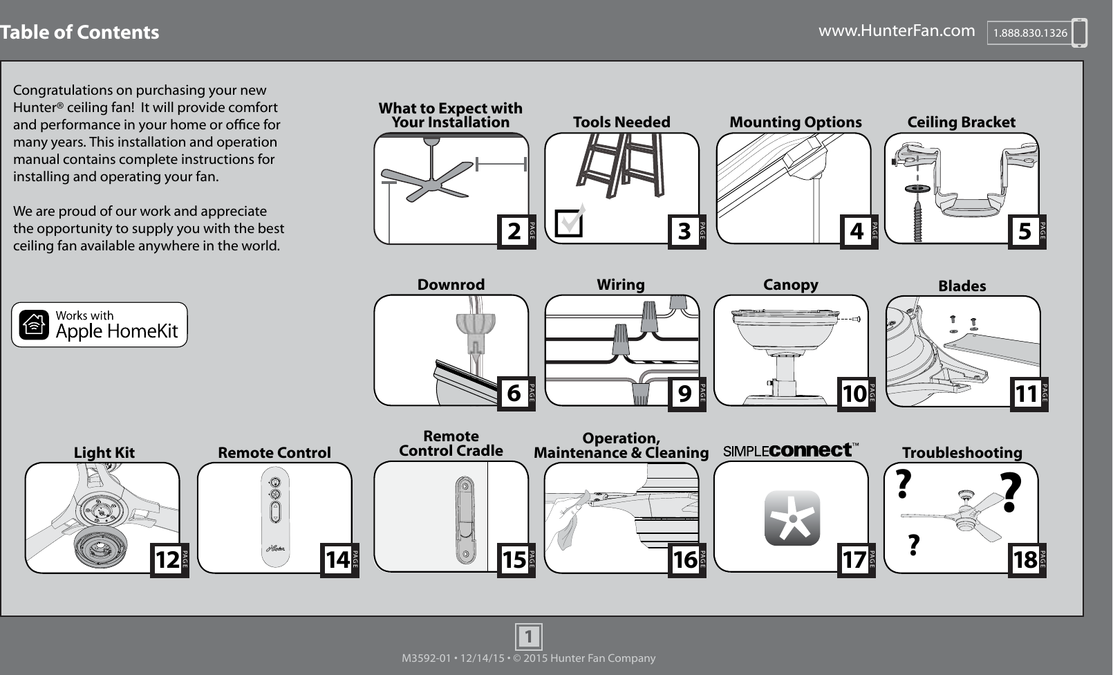
Hunter Fan TX45 Remote Control for Ceiling Fan User Manual Manual

Hunter Fan Company Remote Control for Ceiling Fan Manual

Manual

www.HunterFan.com 1.888.830.13261M3592-01 • 12/14/15 • © 2015 Hunter Fan CompanyPAGE530 inches7 feetPAGE2What to Expect with Your Installation Ceiling BracketLadderPAGE3Tools NeededTroubleshootingTable of ContentsPAGE9WiringPAGE6DownrodPAGE15Remote Control CradleCanopyPAGE10PAGE17PAGE4Mounting Options???PAGE18Congratulations on purchasing your new Hunter® ceiling fan!  It will provide comfort and performance in your home or ofce for many years. This installation and operation manual contains complete instructions for installing and operating your fan.We are proud of our work and appreciate the opportunity to supply you with the best ceiling fan available anywhere in the world.Light KitPAGE12PAGE16Remote ControlPAGE14Operation, Maintenance & Cleaning PAGE11Blades
www.HunterFan.com 1.888.830.13262M3592-01 • 12/14/15 • © 2015 Hunter Fan CompanyWhat to Expect with Your InstallationKnow your wiringIf you are unfamiliar with wiring, use a qualied electrician.You may need a friend to help you.Check box to see fan weightAssess location30 inchesfrom blade tip to nearest wall or obstruction 7 feetfrom bottom edge of blade to the oorSelect a downrod lengthAssess ceiling angleMust be able to secure the fan to building structure or fan-rated outlet box123Standard Downrodfor ceilings 8-10 feet highShorter Downrodfor fans installed close to ceilingLonger Downrodfor ceilings 10 feet or higherCeiling angles greater than 34° will require an Angled Mounting Kit. See page 4 for details.w.1 - To reduce the risk of re, electrical shock, or personal injury, mount fan directly from building structure and/or an outlet box marked acceptable for fan support of 70 lbs (31.8 kg) and use the mounting screws provided with the outlet box.w.2 - To avoid possible electrical shock, before installing or servicing your fan, disconnect the power by turning off the circuit breakers to the outlet box and associated wall switch location. If you cannot lock the circuit breakers in the off position, securely fasten a prominent warning device, such as a tag, to the service panel.w.3 - To reduce the risk of re, electrical shock, or motor damage, use only Hunter Solid State Speed Controls.w.4 - To reduce the risk of personal injury, do not bend the blade brackets when installing the blade brackets, balancing the blades, or cleaning the fan. Do not insert foreign objects in between rotating fan blades.c.1 - All wiring must be in accordance with national and local electrical codes ANSI/NFPA 70. If you are unfamiliar with wiring, use a qualied electrician. c.2 - Use only Hunter replacement parts.This equipment has been tested and found to comply with the limits for a Class B digital device, pursuant to part 15 of the FCC Rules. These limits are designed to provide reasonable protection against harmful interference in a residential installation. This equipment generates, uses and can radiate radio frequency energy and if not installed and used in accordance with the instructions may cause harmful interference to radio communications.However, there is no guarantee that interference will not occur in a particular installation. If this equipment does cause harmful interference to radio or television reception, which can be determined by turning the equipment off and on, the user is encouraged to try to correct the interference by one or more of the following measures: •  Reorient or relocate the receiving antenna. •  Increase the separation between the equipment and receiver. •  Connect the equipment into an outlet on a circuit different from that to which the receiver is connected. •  Consult the dealer or an experienced radio/TV technician for help.Caution: modications not approved by the party responsible for compliance could void user’s authority to operate the equipment.This device complies with Part 15 of the FCC Rules.  Operation is subject to the following two conditions: (1) This device may not cause harmful interference, and (2) this device must accept any interference received, including interference that may cause undesired operation.Read and Save These InstructionsThis product conforms to UL Standard 507.WARNINGSCAUTIONS
www.HunterFan.com 1.888.830.13263M3592-01 • 12/14/15 • © 2015 Hunter Fan CompanyTools NeededLadderPower Drill (optional)9/64” Drill Bit (optional)ScrewdriversPliers Wire StrippersIf mounting to a support structure, you will also need these tools.
www.HunterFan.com 1.888.830.13264M3592-01 • 12/14/15 • © 2015 Hunter Fan CompanyIf you have an angled ceiling:1. You will need a longer downrod (sold separately).2. If your ceiling angle is greater than 34°, you will       also need an Angled Mounting Kit (sold separately). Guide Touches BOTH Ceiling & WallSITUATION 1  Guide Touches Wallbut NOT CeilingSITUATION 2You need BOTH a Longer Downrod & an Angled Mounting KitYou need ONLY a Longer Downrod*most commonIf you have a at ceiling:Hang your fan by a standard downrod (included).Mounting OptionsUse Standard Mounting or Low-Prole Mounting to hang the fan from a at ceiling.Use Angled Mounting to hang the fan from a vaulted or angled ceiling. 34OCEILINGWALLOPTION 1StandardMountingOPTION 2Angled Mounting2 3SLIDE toward ceilingPLACE against wall1FOLD on dotted line34°Use the three steps below to determine if your ceiling angle is greater than 34°Support StructureCeiling Outlet Box (required)Angled Mounting StyleStandard Mounting StyleSupport StructureCeiling Outlet Box (required)
www.HunterFan.com 1.888.830.13265M3592-01 • 12/14/15 • © 2015 Hunter Fan CompanyCeiling BracketRefer to warning w.1 on pg. 2To avoid possible electrical shock, before installing your fan, disconnect the power by turning off the circuit breakers to the outlet box associated with the wall switch location.For angled ceilings, point opening toward peak.If you are unable to do this, call Technical Support at 1-888-830-1326.Make sure all four bumpers are still attached. Use wood screws (included) when securing to support structure with approved electrical outlet box. Drill 9/64” pilot holes in support structure to aid in securing ceiling bracket with hardware found in the       hardware bag.Use machine screws (provided with outlet box) when securing to existing ceiling fan-rated outlet box. Make sure it is securely installed and is acceptable for fan support of 31.8 kg (70 lbs) or less.OFFTurn Power
www.HunterFan.com 1.888.830.13266M3592-01 • 12/14/15 • © 2015 Hunter Fan CompanyDownrodSlideSlide1 2 3 4 5678910Sold SeparatelySold SeparatelyLonger Downrodfor angled ceilings or ceilings 10’ or higherShorterDownrodfor fans installed close to ceilingStandardDownrodfor ceilings 8-10’ highOption 1Option 2Option 3skip to next pageIf you need a different downrod length follow these steps:Steps 1-5 to remove standard downrod pipeSteps 6-10 to reassemble with new pipeIncluded (pre-assembled)
www.HunterFan.com 1.888.830.13267M3592-01 • 12/14/15 • © 2015 Hunter Fan CompanyKEEP!8”3/8”CUT& STRIP(not to scale)Remove the pre-installed setscrew so that the downrod can be inserted.Hand tighten the downrod (at least 4-5 full turns) until it stops.The wires can be cut, but leave at least 8” extending from the top of the downrod.Downrod (continued)8” 3/8”Tighten the setscrew with pliers. DO NOT HAND TIGHTEN. If the setscrew is not tightened securely, the fan may fall.KEEP!
www.HunterFan.com 1.888.830.13268M3592-01 • 12/14/15 • © 2015 Hunter Fan CompanyDownrod (continued)Put the wires and downrod through the canopy. Let the canopy sit loosely on top of the fan.DO NOT PICK THE FAN UP BY THE CANOPY OR WIRES. Place the downrod ball into the slot in the ceiling bracket.
www.HunterFan.com 1.888.830.13269M3592-01 • 12/14/15 • © 2015 Hunter Fan CompanyNote: If you have a dual switch, please cap the secondary power wire from the ceiling. This will result in one unused switch.WiringFROM FANFROM CEILING BRACKETFROM FANUsing an orange wire connector from the        hardware bag, connect the 3 grounding wires (green, green/yellow stripe, or bare copper) coming from the ceiling, downrod, and hanging bracket. (Grounding) Green/Yellow StripeGreen/Yellow StripeWhiteBlack(Grounded)Note: To connect the wires, hold the bare metal leads together and place a wire connector over them, then twist clockwise until tight.Not for use in applications where the fan does not have a wall switch.Using the orange wire connectors from the        hardware bag, connect the black wire (ungrounded) from the ceiling to the black from the fan. Connect the white wire (grounded) from the ceiling to the white wire from the fan. Cap the blue wire from the fan with an orange wire connector. It will not be used for single switch wiringUsing the orange wire connectors from the        hardware bag, connect the white wire (grounded) from the ceiling to the white wire from the fan.Connect the black wire (ungrounded) from the ceiling to the black wire from the fan. Connect the second (ungrounded) wire from the ceiling to the blue wire from the fan.FROM FANWhite  (Ungrounded)BlackBlue(Grounded)FROM CEILING   (Ungrounded)BlueFor Dual SwitchesFor a Single Switch FROM CEILING FROM CEILINGTurn the splices upward and push them carefully back through the hanger bracket into the outlet box. Spread the wires apart, with the grounded wires on one side of the outlet box and the ungrounded wires on the other side of the outlet box.Refer to CAUTION c.1 on pg. 2 (Ungrounded)
www.HunterFan.com 1.888.830.132610M3592-01 • 12/14/15 • © 2015 Hunter Fan CompanyCanopyPosition the canopy so that, when lifted into place, the canopy ts into the hanging bracket as shown.Lift the canopy into place so that the screw holes are aligned. Screw HolesInsert the two canopy screws found in the        hardware bag.
www.HunterFan.com 1.888.830.132611M3592-01 • 12/14/15 • © 2015 Hunter Fan CompanyBladesPut the blade washers found in the   hardware bag onto the blade screws found in the   hardware bag. Then install the blade screws to secure each blade to a blade iron.
www.HunterFan.com 1.888.830.132612M3592-01 • 12/14/15 • © 2015 Hunter Fan CompanyLight KitLight KitScrew two housing assembly screws from the   hardware bag halfway into the motor housing. It does not matter which two screw holes you choose.Wrap keyhole slots around the screws and twist counterclockwise.Insert the third screw, found in the  hardware bag, into place and then tighten all three screws.
www.HunterFan.com 1.888.830.132613M3592-01 • 12/14/15 • © 2015 Hunter Fan CompanyLight Kit (continued)CONGRATULATIONS!YOU’RE DONE!See next page for remote operation instructions.Connect the white wire from the fan to the white wire from the light kit. Then, connect the blue wire from the fan to the black wire from the light kit.Lift the globe and align the notches in the globe with the tabs in the light kit. Attach the globe by lifting and twisting counterclockwise until it rests rmly in place.
www.HunterFan.com 1.888.830.132614M3592-01 • 12/14/15 • © 2015 Hunter Fan CompanyRemote ControlTo access the battery compartment, remove the small Phillips head screw that secures the battery door to the transmitter assembly. The battery should be installed with the positive (+) side up. Replace with a CR2032 battery when necessary. Phillips Head ScrewBattery Door ONTurn PowerThe remote transmitter is already paired to the receiver and ready to use.Note: If your need to pair your remote, remove the battery door. Cycle power to the fan by turning power off and back on at the wall switch (or circuit breaker if necessary). Within three minutes, press the pair button on the remote. If pairing was successful, a single beep will sound. If three beeps sound, the remote was unpaired. Re-pair using the steps above.  To prevent faulty operation, please disconnect power from all other ceiling fans within range while pairing.
www.HunterFan.com 1.888.830.132615M3592-01 • 12/14/15 • © 2015 Hunter Fan CompanyRemote Control CradleOption 1: Using ScrewsOption 2: Using Adhesive StripInstall the cradle bracket to the wall with the included screws.You have two options to install the included remote control cradle to the wall. Choose which path works best for you.Choose your cradle installation location.If you are installing into drywall, drill two 9/64 width holes using the cradle bracket as a guide. Gently hammer the included drywall anchors into the pre-drilled holes. Press the cradle bracket against the wall and hold rmly for 30 seconds.Separate the lining from the back of the adhesive strip on the cradle bracket.Slide the cradle onto the mounted bracket.Remove the cradle from the cradle bracket.
www.HunterFan.com 1.888.830.132616M3592-01 • 12/14/15 • © 2015 Hunter Fan CompanyFan Operation:Press and quickly release the fan button on the remote control to turn the fan OFF or ON. Use the fan control directional pad to raise or lower the fan to the desired speedLight Operation:Press and quickly release the light button on the remote control to turn the light OFF or ON. Press and hold the light button for continuous dim.Operation, Maintenance, and CleaningLight ButtonFan ButtonFan ControlCleaning the fan - use soft brushes or cloths to prevent scratching. Cleaning products may damage the nishes.Slide the remote into the cradle when not in use.
www.HunterFan.com 1.888.830.132617M3592-01 • 12/14/15 • © 2015 Hunter Fan CompanyNote: The HomeKit identication number is located on the front cover of the English side of the Parts Guide.  SIMPLEconnect connects to available 2.4 GHZ WiFi networks. Launch the app.Follow the onscreen prompts to set up your fan.Download the app:Visit your app store and search simpleconnect to nd the app.123
www.HunterFan.com 1.888.830.132618M3592-01 • 12/14/15 • © 2015 Hunter Fan CompanyTroubleshooting    Excessive wobbling•  Make sure the blades are properly installed on the blade iron posts.•  Turn the power off, support the fan carefully, and check that the hanger ball is properly seated.•  Use the provided balancing kit and instructions to balance the fan.    Noisy Operation•  Make sure the blades are properly installed on the blade iron posts.•  Check to see if any of the blades are cracked. If so, replace all of the blades.    Wireless Issues•  Reset the Wi-Fi module by removing the battery door. Press and hold the reset button for 5 seconds. The fan and light LEDs will flash once the module has been reset.     Fan doesn’t work•  Make sure power switch is on.•  Pull the pull chain to make sure it is on.•  Push the motor reversing switch rmly left or right to ensure that it is engaged.•  Check the circuit breaker to ensure the power is turned on.•  Make sure the blades spin freely.•  Turn off power from the circuit breaker, then loosen the canopy and check all the connections according to the wiring diagram on pages 9.•  Check the plug connection in the switch housing.    Remote control of fan is erratic•  Make sure the battery is installed correctly.•  Install a fresh battery. Transmitter only works when held at close range•   Change battery.If you have multiple remotes or multiple remote-controlled fans installed on the same circuit breaker and you are experiencing interference or faulty operation of your remote controls, please go to  www.HunterFan.com/FAQs and click “How do I properly install multiple remote-controlled fans?” for information on how to correct this issue.Use of the HomeKit logo means that an electronic accessory has been designed to connect specically to iPod, iPhone, or iPad, respectively, and has been certied by the developer to meet Apple performance standards. Apple is not responsible for the operation of this device or its compliance with safety and regulatory standards. Please note that the use of this accessory with iPod, iPhone, or iPad may affect wireless performance.Compatible with iOS 7.1 or higher / Android 4.3 or higherAndroid and Google Play are trademarks of Google Inc.Apple logo is a trademark of Apple, Inc.App store is a service mark of Apple, Inc.

Navigation menu