Hunter ICDHP Decoder System User Manual ICD HP Owners Manual
Hunter Industries Inc Decoder System ICD HP Owners Manual
Hunter >
Users Manual
1
ICD‐HP
HandheldProgrammerfor
HunterICDDecoders
Owner’sManualandOperatingInstructions
2
Introduction.............................................................................................................................................................................3
ICD‐HPComponents................................................................................................................................................................5
InstallingtheBatteries.....................................................................................................................................................7
KeypadFunctions.............................................................................................................................................................8
CableandLeadConnections............................................................................................................................................9
ConnectingtoaDecoder.................................................................................................................................................9
Operations.............................................................................................................................................................................11
MainMenu&Navigation...................................................................................................................................................11
ICD‐HPSet‐up.................................................................................................................................................................12
DecoderProgrammingMenu........................................................................................................................................13
DecoderFirmware.........................................................................................................................................................23
3
Diagnostics.....................................................................................................................................................................25
Troubleshooting.....................................................................................................................................................................27
Specifications.........................................................................................................................................................................29
FCCNotice..............................................................................................................................................................................30
IndustryCanadaNotice..........................................................................................................................................................31
CE&AUSTRALIANOTICE........................................................................................................................................................31
Introduction
TheICD‐HPHandheldProgrammerisaninnovativesetup,programming,anddiagnostictoolforHunterICDseries
decoderproducts.
ThisinstrumentcanoperateandprogramICDdecodersviawirelessinduction,throughthebaseofthedecoder,witha
specialprogrammingcup.Thisallowsaccesstoinstalleddecoders,withoutremovingwaterproofwireconnectors.
ICD‐HPcanalsobeusedforinitialsetupofnewdecoders.Theincludedpowerleadswillpoweradecoderfor
programmingpurposes,forinstallationlater.
ICD‐HPcanbeusedfordiagnosticoperationandtestingofinstalleddecoders,solenoids,andevensensors.
4
ICD‐HPcanenablenewprogrammingoptionsforICDdecoders.Itcanprogramanystationnumbersinanyorderwithina
multi‐stationdecoder,andcan“skip”stationstoreservethemforfutureuse.
5
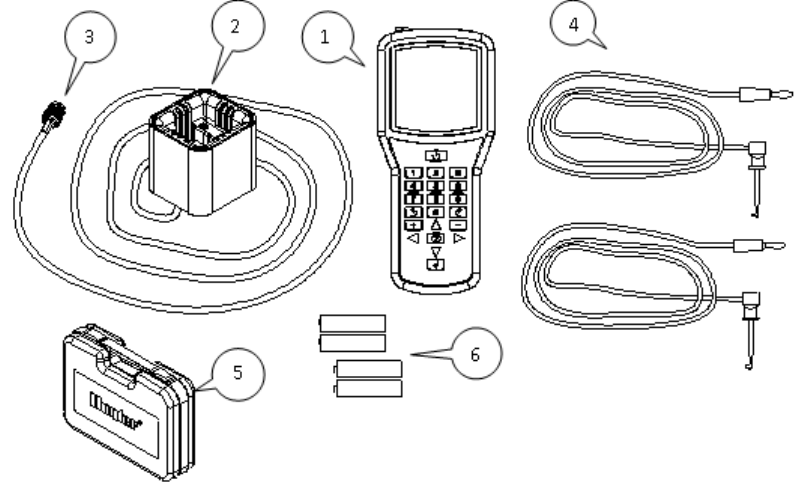
ICDHPComponents
ICD‐HPispackagedwithrequiredaccessories.

6
TheProgrammingCableisNOTastandardBNCconnectorcable,
andcannotbereplacedwithastandardcoaxialBNCcable.
ThisitemisuniquetotheICD‐HPprogrammer.
DonotattempttousetheICD‐HPprogrammingcableforany
otherpurpose!
Item Part Description
1 ---- ICD-HP Programmer
2 205700 Programming Cup
3 180504 Programming Cable 6’/2m with
connectors
4 180508 Red and Blue 6’/2m leads
5 ---- Carrying Case
6 ---- 4 x AA batteries
7
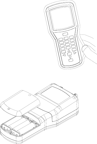
InstallingtheBatteries
TheICD‐HPprogrammeroperateswith4xAAbatteries.Thebatteriessuppliedarenot
rechargeable!
Toinstallbatteries:
RemovecablesandconnectorsfromendofICD‐HP.
PrytheyellowflexibleyellowbootofftheICD‐HP.
TurntheICD‐HPover,andremovethe2screwssecuringthebatterycompartmentcover
withasmallscrewdriver(eitherstandardorPhilips).
Insert4freshAAbatteriesasshown,observingpolarity.
Replacecoverwithscrewsandsecure.
Replaceyellowboot.
8
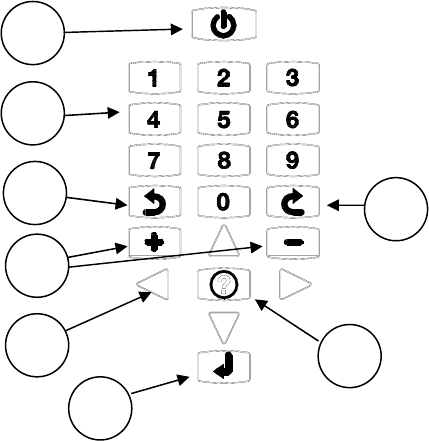
KeypadFunctions
1. Powerbutton.
2. Numberbuttons,usedtoenterstationnumbersand
othernumericdata.
3. Backbutton.Returnstopreviousmenu.
4. PlusandMinus(+/‐)buttons.Usedtochangestation
numbers,andalsototurnstationsOn(+)andOff(‐).
5. Arrowbuttons.Usedtonavigatewithinscreens,move
pointers,orchangeoutputsonmulti‐stationdecoders.
6. Enter.Usedmostlytoretrycertainfunctions.
7. Question/Info.Usedtoswitchpages,insomescreens.
AlsousedtoenterICD‐HPflashmode.
8. Nextbutton.Usedtoselectamenuitemandgotothe
nextlevel.Alsousedtoexecutecertaincommands.
1
2
8
3
7
4
6
5
9
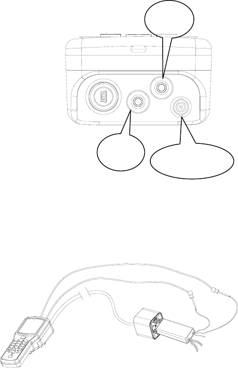
CableandLeadConnections
RedandBlueLeads:Connectthestraightconnectorsbypushingallthe
wayintotheappropriatelycoloredplugs.
ProgrammingCable:Connecteitherendofthesuppliedcabletothe
connectorontheICD‐HP.Alignconnectorslotswithfemaleconnectoron
programmer,pushstraightin,andturn90degreesuntiltheconnector
locksintoplace.
ConnecttheotherendoftheProgrammingCabletotheProgramming
Cupinthesameway.
ConnectingtoaDecoder
TheICD‐HPprogrammerworkswithHunterICDandlaterdecoders.The
ICD‐HPprogrammingcupcommunicateswithdecodersthroughwirelessinduction.
Thebottomendofthedecoder(oppositetheendwiththewires)isthereceiverareaforthesignalsfromthe
programmingcup.
Theentireinsideofthecupiswithinthewirelessrange,
anditisnotnecessarytopressdecodersfirmlyinplace,as
longastheyarewithinthecup.Theprogrammingcup
Blue
Lead
Red
Lead
Programming
Cable
10
doeshavepocketsforthetwodifferentsizesofdecoder,andthesewillhelpholdthecupanddecodertogetherfirmlyin
fieldapplications.
BenchMode:Ifthedecoderisuninstalled,andnotconnectedtothetwo‐wirepath:
InstalltheredandbluewireleadsfortheICD‐HP.
ConnecttheprogrammingcuptotheICD‐HP.
Cliptheredandblueleadstothedecoderredandblueleads.
Placethedecoderintheprogrammingcup.
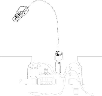
FieldMode:Ifthedecoderisinstalledinthetwo‐wirepath,itis
notnecessarytodisconnectanydecoderwiring.
ConnecttheprogrammingcuptotheICD‐HPwiththe
programmingcable.
Wipemudanddirtoffthedecodertopreventwearon
theprogrammingcupandinterferencewiththesignal.
11
Seattheprogrammingcupoverthedecoder.Thebottomofthedecoder(theendwithnowires)shouldbe
withintheprogrammingcup.
Verifythatthetwo‐wirepathisconnectedtothecontroller,andthatcontrollerpowerison.
Thedecoderwillbepoweredoverthetwo‐wirepath,andtheredandblueICD‐HPleadswillnotbenecessary.
ProtecttheICD‐HPfromsprinklersprayandotherwatersources!
Operations
Turntheprogrammeronwiththepowerbutton.Thelogowillappear,andchangetotheMainMenuinafewseconds.
MainMenu&Navigation
Forthefirstuse,ortochangegeneralsettings,selectICD‐HPSetup.
MostmenuselectionsthroughoutICD‐HPoperatewiththesamebuttons.Usethearrowkeystonavigatearoundthe
screens.Usethe+and–buttonstochangethechoicesinsettings.UsetheNext3buttontoselectanoption,andgoto
thenextscreen.UsetheBack4buttontoexitandreturntothepreviouslevel.
Insomeselections,theEnterbutton isusedtomakeselections.
12
ICD‐HPSet‐up
LCDSettings:AdjustscreenappearancewithContrast,Backlight,andBacklightTimeoutcontrols.Usethearrowbuttons
tomovetotheitemyouwishtochange,andpressthe+or–buttonstoadjustthesettings.
Increasingthecontrastandbacklightcanimprovevisibilityinlowlightconditions,butwillalsoconsumebatteriesmore
quickly.Thebacklightwillturnoffautomaticallyafteraperiodofnouse.ThetimeisselectableunderBacklightTimeout
controls,orthebacklightcanbeturnedofftopreservebatterylife.
SetLanguages:Selectoperatingsystemlanguageofyourprogrammer.
Usetheup/downarrowkeystosetthepointertoyourselection.
UsetheNext3buttontomaketheselection,andthedisplaywillshowtheselection.
PresstheBack4buttontoexit.
SetUnitsofMeasure:ChangebetweenEnglishandMetricreadings(GPMorLPM).
Usetheup/downarrowkeystosetthepointertoyourselection.
UsetheNext3buttontomaketheselection,andthedisplaywillshowtheselection.
PresstheBack4buttontoexit.

13
CurrentDecVersions:ShowsthecurrentversionsofdecoderfirmwareloadedintoICD‐HP.Ifyouflashupdatea
decoder’soperatingsystem,thisistheversionthatwillbeloaded.
DecoderProgrammingMenu
Installadecoderwitheithermethodin“ConnectingtoaDecoder”section.
FromtheMainMenu,usethearrowkeystopointtoDecoderProgramming,
andpresstheNext3button.TheDecoderProgrammingMenuwillappear.
Usethearrowstomovethepointertoanyfunction,andpressNext3toselectit.
GetDecoderInfowillcheckthedecoderanddisplayitscurrentsettings.Itwill
notchangeanyofthesettingsinthedecoder.Itcanbeusedtoidentifythe
stationnumber(s)andothersettingsofanyICDorlaterdecoder.
DecTypeshowsifthedecoderisastationdecoderandthenumberof
stations,orPumpdecoder,orSensordecoder.
DECODER PROGRAMMING
----------MENU---------
Get Decoder Info
Program Decoder
Get Decoder Status
DECODER INFO
----------------------
Dec Type: 2-Station
Output #: 1
Station #: 007
Serial #: ########
◄/►Change OUTPUT #
Press ? For More
DECODER INFO
----------------------
Dec Type: 2-Station
Pwr Factor: 2
Inrush: 5
Serial #: ########
Version: 1.01.005
Press ? To Return
14
Output#:Ifthedecoderisamulti‐stationdecoder,thedisplayonlyshowsthestationaddressofoneoutputatatime.
Eachcolor‐codedpairofwiresfromthedecoderisadifferentoutput.
Presstheleftandrightarrowbuttonstomovethroughthedifferentoutputs,andviewthestationnumbersforeach
output.
DecoderInfoscreensmulti‐pagescreens.Pressthe?buttonforMore.ThesecondpagewillshowthePowerFactor,
Inrushsetting,andVersionofthedecoderfirmware.Press?againtoreturntothefirstpage.
Serialnumbersarenotusedtoaddressdecoders,exceptinolderHunterdecodercontrollers(IDS,GenesisandVSX
“Viking”decodersystems).Serialnumberscannotbechanged.

15
ProgramDecoderwillenterthestationaddressesandothersettingsofthedecoder.
MovethepointerwiththearrowbuttonsattheMainMenuscreento
ProgramDecoderandpressNext3.
TheICD‐HPwillcheckforadecoder.Ifsuccessful,itwilldisplaytheType,
PowerFactor,andInrushinformationforthedecoderafterafewseconds.
Type:Pressthe+and–buttonstochangethedecodertype.Itispossibleto
changeastationdecodertoPump,toassignittooneoftheP/MV
(Pump/MasterValve)outputsforthecontroller.Itisbesttouseasingle‐
stationdecoderforaP/MVoutput.Ifamulti‐stationdecoderissettoType
Pump,theotheroutputscannolongerbeused,andwillbewasted.
IftheTypeshownis“Sensor”,theICD‐HPisreadingaSensorDecoderandthe
Typecannotbechanged.
PwrFactor:PowerFactor.Defaultsettingis2andthisistherecommended
setting.ThePowerFactorcanbeincreasedforcertainhighcurrent
requirements(suchasPumpStartRelays),butthiscandegradeperformance
forotherstationsontheline.Changeonlywhenrequired.
PROGRAM A DECODE
R
----------------------
Dec Type: 6-Station
Pwr Factor: 2
Inrush: 3
Press 3 To Continue
-PROGRAM A DECODE
R
--
Output 1: Sta-027
Output 2: Sta-000
Output 3: Sta-000
Output 4: Sta-000
Output 5: Sta-000
Output 6: Sta-000
Press 3 To Program

16
Inrush:Thiscanchangetheinrushtimingforthestationorrelaywhenfirstturningon.Defaultsettingis3,andthisrarely
needstobechanged.ConsultHunterTechnicalSupportbeforechangingtheInrushvalue.
PressNext3tocontinue.
AssignStationNumbers:Thenextscreenwillshowthestationnumberassignedtoeachdecoderoutput.Thenumberof
outputsisbasedonthedecoder’ssize.Asinglestationdecoder(ICD‐100)willonlyshowoneoutput.Atwo‐station
decoder(ICD‐200)willshowtwooutputlines,etc.
Usetheupanddownarrowstomovethepointertoeachoutput.Usethenumberkeystotypethecontrollerstation
numberyouwishtoassigntoeachoutput.Or,usethe+and–keystoraise
andlowerthestationnumbers.
Ifyouhavealreadyassignedastationnumbertoanoutput,usingthe+and–
buttonstochangeanotheroutputwillskipoveranystationnumberthathas
alreadybeenassigned.
Example:Output1isassignedSta‐007.WhensettingOutput2,usingthe+/‐
buttonswillskip007andmovedirectlyfrom006to008.
Ifnumbersareentereddirectlyfromthekeypad,itmaytemporarilypermita
duplicate,butthiswillnotbesenttothedecoder.Ifaduplicatestation
numberisenteredinamulti‐stationdecoder,andtheNext3buttonis
-PROGRAM A DECODE
R
--
Output 1: Sta-001
Output 2: Sta-002
Duplicate Sta-003
Duplicate Sta-003
Press 3 To Program
Flashing“Duplicate”showsduplicatestation
numbers‐changeaddressbefore
programming.
17
pressed,theICD‐HPwillrefusetosendtheprogramuntiltheduplicatenumbershavebeenchanged.
Theoutputswithduplicatenumberswillflash“Duplicate”,alternatingwiththeoutputnumbers.
Pump:IftheTypewaschangedtoPump(insteadofastationdecoder),onlyOutput1willbeshown.Use+and–to
changebetweenP/MV‐1andP/MV‐2.(P/MV=Pump/MasterValve).
Programming:Whenallsettingsaremade,andoutputsarenumbered(seeImportantNotessection),presstheNext3
buttontosendthestationnumberstothedecoder.
Thedisplaywillshow“Programming…”forashorttime.Ifsuccessful,“ProgrammingComplete”willappearafterthe
programhasbeensent.
Decodercommfailed:Thismessageindicatesthattheprogrammingwasnotsuccessful.Mostlikelycausesarethe
connections,orthedecoderpower.Checkpowerleadstothedecoder,programmingcupcableconnections,andverify
thereispoweronthetwo‐wirepathfromthecontroller(ifprogramminginline).
TurnLinePowerOff,andBackOn:Afterprogrammingorre‐programminginstalleddecoders,thetwo‐wirepathpower
mustbeturnedofffor15seconds,andthenbackon,fortheprogrammingtotakeeffectinthefield.
Thestationnumberswillbeinthedecoder’smemory,butthepowermustbecycled(off/on)totakeeffect.Youcanturn
offpowertothecontroller,orremovetheADM99outputmodulefromthecontroller,andthenplugitbackinafter15
seconds.

18
ImportantNotes:
Outputsmaybeassignedfrom000to500.Donotassignastationnumberhigherthanthecapacityofyourcontroller,or
itwillnotoperate!(Example:ACC99Dhas99stationcapacity.Donotprogramastationnumberhigherthan99).TheICD‐
HPdoesnotknowthecapacityofyourcontroller.
ReservedStations:Itispossibletoassign“000”toadecoderoutputwiththeICD‐HP.Thisoutputwillnotbeused.
However,itmaybeprogrammedatalaterdate,toaddanewstationtoa
multi‐stationdecoder.
Forexample,asix‐stationdecodercouldhaveoutput#6(oranyother
outputs)settostation000.The000outputswouldnotbeoperational,but
couldbereservedforfutureadditions.Thenthenewstationnumbercould
beassignedtothereserved000outputwiththeICD‐HP.
Donotassignastation000unlessyouwishtoskipastation,orreserveone
forfutureexpansion.Stationnumber000cannotbeturnedonbya
controller!
StationsinRandomOrder:Itispossibletoassignanyvalidstationnumbersinanyorder.TheICD‐HPcanenterany
stationnumbersinamulti‐stationdecoderinanyorder.Thiscannotbedonefromthecontroller’sdecoderprogramming,
butisanaddedfeaturewithICD‐HP.
-PROGRAM A DECODE
R
--
Output 1: Sta-001
Output 2: Sta-032
Output 3: Sta-025
Output 4: Sta-081
Output 5: Sta-014
Output 6: Sta-000
Press 3 To Program
SampleICD‐600displaywithrandomstation
numbersandOutput6heldinreserve(000).

19
Donotassignduplicateaddresses!Nodecodercontrollershouldhaveduplicatestationnumbers,anywherewithinthe
entiresystem.(Thisdoesnotapplytostation000,however.)
TheICD‐HPwillnotallowduplicatestationnumberswithinasingledecoder,butitcannotdetectduplicateselsewherein
thesystem.
SensorDecoderProgramming(ICD‐SEN)
IfthedecoderintheprogrammingcupisanICD‐SENsensordecoder,only
theaddresscanbeset.TheTypewillbeSensor,andthiscannotbe
changedwhenasensordecoderisfound.
Chooseanaddressbetween1‐5withthe+or–buttons,andpressNext3
tosendtothesensordecoder.
TurnLinePowerOff,andBackOn:Afterprogrammingorre‐programming
installeddecoders,thetwo‐wirepathpowermustbeturnedofffor15seconds,andthenbackon,fortheprogramming
totakeeffectinthefield.
OtherSensorDecodersetupoptionsaremadeatthecontroller,andnotfromtheICD‐HP.Consultcontrollerand/or
sensordecoderdocumentationforcompletesetupinstructions.
GetDecoderStatus
PROGRAM A DECODE
R
----------------------
Dec Type: Sensor
Address: 0

20
Connecttoanydecodertoviewstatus,foridentificationanddiagnostics.Thiscanbeusedwitheitherinstalleddecoders,
ordisconnecteddecodersthatarepoweredthroughtheICD‐HPpowerleads.
FromtheMainMenu,selectDecoderProgrammingwiththeNext3button.Movethepointerwiththeup/downarrows
toGetDecoderStatus,andpressNext3againtoselect.TheICD‐HPwillattempttocommunicatewiththedecoder.
Whenadecoderisfound,thestatuswillbedisplayed.
StationDecoders:IfthedecoderisaStationOutputdecoder,thedisplaywill
showthefollowinginformation.
DecState:CanbeNormal,Fault,orDamaged.
Normal:Decoderisrespondingcorrectly.
Fault:Decoderoutputwiresareshortedorsolenoidcoilisshorted.
Thisdoesnotindicateaproblemwiththedecoder!Checkfield
wiringandsolenoid.
Damaged:Thereisaproblemwiththedecoder,anditshouldbereplaced.Damagedindicatesthedecoderis
“leaking”voltageontheoutputswhenitshouldbeoff.
DECODER STATUS
----------------------
Dec State: Normal
Current: 167mA
Output #: 1 2 3 4 5 6
Solenoid: Y Y Y Y Y N
Active : Y Y Y Y N N
NormalDecoderhas5solenoidsdetected,
with4stationsrunning(Active).
21
Decodercommfailed:Thismayindicateacompletedecoderfailure,ORthedecodermaynotbeconnectedor
poweredproperly.VerifyALLconnections:ICD‐HPtoprogrammingcup(bothends)anddecoderpower.Ifthe
decoderisconnectedinthetwo‐wirepathbutthecontrollerpowerisOff,decoderwillnotrespond.Ifdecoder
andICD‐HPareconnectedcorrectly,anddecoderhaspower,andDecodercommfailedmessageappears,
decoderislikelydefective.
Current:Displayselectricalcurrentdrawofdecoderinmilliamps.Standbyrangeisapproximately3‐5ma.Whendecoder
isactive,thisvaluewillbehigher,dependingonnumberandtypeofdevicesconnectedtodecoderoutput.Totalcurrent
onadecodercannotexceed1000ma.
Thecurrentdisplaydoesnotchangeinrealtime.Ifastationisstartedorstopped,runthediagnosticGetDecoderStatus
againtoseethenewcurrentdraw.
Output:Theoutputmatrixshowsthestatusofeachoutputofthedecoder.Thedisplaywillshowthenumberofoutputs
forthesizeofdecoderdetected(asinglestationdecoderwillonlyhave1output).
Solenoid:Showswhetherasolenoidorsimilardeviceisdetectedontheoutput(Y=Yes,N=No).
TheSolenoidstatusmaynotchangeuntilpowerhasbeencycledoff/ontothedecoder,ifasolenoidhasjust
beenaddedtothedecoder.Turnoffeitherthecontroller,orremovetheADM99decoderoutputmodulefrom
thecontroller,forapproximately15seconds,andthenturnthepowerbackon(orreplacetheADM99).Solenoid
statuswillbeupdated.

22
Active:Showswhethertheoutputiscurrentlyturnedon(Y=Yes,N=No).
SensorDecoders:IfthedecoderfoundduringGetDecoderStatusisaSensorDecoder,thedisplaywillshowthestatusof
eachsensorinputtothedecoder’sPorts,onindividualscreens.
UsetheleftandrightarrowstoseeeachPort(AandB)individually.
Cliksensors:ThedisplaywillshowthecurrentstateoftheClikinputas
Closed(normal)orOpen(alarmed).
Flowsensors:Thedisplaywillshowthetypeofflowsensor(setfromthe
controller),thesizeorK‐FactorandOffset,andthecurrentactualflowin
GPMorLPM(dependingonUnitofMeasurementsettings).
TheICD‐HPisnotusedtosetorchangeflowsensorsettings.Itshowswhat
thecontrollerhassenttothesensordecoder,anddisplaysthecurrentflow.
TheflowsensorisalwaysconnectedtoPortAofthesensordecoder.Use
theleftandrightarrowstoviewPortB,whichcanbeusedforCliksensor
inputs.
Theflowreadingwillupdatechangesinflowlive,inthescreendisplay,as
SENSOR STATUS #
----------------------
Port A Type: Clik
State: Closed
◄/► To Change Port
SENSOR STATUS #
----------------------
Port A Type: FLOW
Sensor: HFSFCT150
Flow Rate: xxxx.x GPM
◄/► To Change Port

23
valvesopenandclose.
DecoderFirmware
Thedecoderfirmwaremenuchecks,andhastheabilitytoupdate,adecoder’soperatingsystem(firmware).
FromtheMainMenu,usetheup/downarrowstomovethepointertoDecoderFirmware,andpressNext3.Thedisplay
willshowtwooptions,GetDecoderVerandUpdateDecFirmware.
GetDecoderVer:MovethepointertoGetDecoderVerandpressNext3.Thiswillcheckthedecoder,anddisplaythe
versionnumber.
UpdateDecFirmware:MovethepointertoUpdateDecFirmwareandpress
Next3.Thiswilldisplaythe“LatestVersion”loadedintotheICD‐HP,and
displayitabovetheversionfoundinthedecoder.Iftheversionsaredifferent,
youhavetheoptiontoloadthelatestversionintothedecoder.
Note:The“LatestFirmwareVersion”isloadedintotheICD‐HPoperating
system.Thiscanbeupdated,ifnewfirmwareisreleased,byre‐flashingthe
ICD‐HPitselffromacomputer.Theupdateswillcontainbothstationdecoder
andsensordecoderfirmwareversionsforthedecoders.
DECODER UPDATE
----------------------
Latest Firmware Version:
#.##.###
Attached Decoder
Version: #.##.###
Press 3 To Continue

24
IftheversioninthedecoderisolderthantheversionloadedintotheICD‐HP,
andyouwishtoupdatethedecoder,pressNext3.Thiswillshowtheversion
ofthe“bootloader”program,whichactuallyloadsthefirmwareintothe
decoder.
PressNext3againtocontinue,andthefirmwareupdatewillbegin.Astatus
barwillshowtheprogressofthedownload.
Itwilltakeseveralminutestoupdateadecoder’sfirmware.Donotdisconnectthedecoderduringthisupdate!The
firmwareupdateshouldalwaysbeallowedtocomplete,onceithasbegun.
Theupdatewillnoterasethedecoderoutputstationaddresses.IfthedecoderisusedasaPump,thisinformationwill
alsoberetained.
IfthedecoderisaSensorDecoder,itwillautomaticallyreceivetheSensor
Decoderfirmware,andtheaddressandportsettingswillberetained.
Astatusscreenwillannouncewhentheupdateiscomplete,andverifythe
newversionnumber.
DECODER UPDATE
----------------------
Update Progress...
DECODER UPDATE
----------------------
!Complete!
Dec Type: X-Station
Station #: ###
Serial #: ########
Version: #.##.###

25
Diagnostics
TheDiagnosticsmenuallowsoperationandtestofdecoderfunctions.
FromtheMainMenu,movethepointertoDiagnosticsandpressNext3.
TurnStationOn/Off:TheICD‐HPcanturnindividualstationoutputsonand
offfordiagnosticpurposes.Thisfunctiononlyworkswithdecoderswiredinto
thetwo‐wirepath,andwillnotoperatewhenpoweredbytheleadsfromthe
ICD‐HP!
Connectadecoderwiththeprogrammingcup.MovethepointertotheTurn
StationOn/Off,andpressNext3.
TheICD‐HPwillfirstconnecttothedecoder,anddisplaythefirststationoutput.Ifthedecoderisamulti‐stationdecoder,
usetheleftandrightarrowbuttonstomovetothestationtoturnonoroff.
Press+toturnastationon.Thestationwillrunforapproximately1minuteifrunningalone,or12minutesifanother
stationisrunningfromthecontroller(seeImportantNoteinthissection).TheStatewillchangefromOfftoOnaftera
fewseconds.
TURN STATION ON/OFF
----------------------
Output #: 1
Station #: ###
Serial #: ########
State: xxx
◄/► To Change Output #
+ On / - Off
26
Ifthestationisconnectedtoapressurizedvalve,thewaterwillturnon.TakecaretokeeptheICD‐HPoutofthewater
fromsprinklers.
Press‐toturnastationoff.ThestationwillturnoffandtheStatewillchangefromOntoOffafterafewseconds.
ImportantNote:TheICD‐HPcannotsetaruntimeforadecoderactivation.TheACCcontrollerwillsendanOffcommand
downthetwo‐wirepathonceperminute,whennostationsaresupposedtoberunning.Ifyouturnastationonwiththe
ICD‐HP,thiscontrollercommandwillturnthatstationbackoff,withinaminute.
Iflongerruntimesarerequiredfordiagnosticpurposes,turnanotherdecoderstationonfromtheACCcontroller,orwith
aremotecontrol(ICR,ROAM,orMaintenanceRadio).Aslongasthisstationisrunningfromthecontroller,the“off“
commandwillnotbesenteveryminute.
Ifanotherstationisrunningfromthecontrollerasdescribed,andastationinthefieldisturnedonwiththeICD‐HP,itwill
runforapproximately12minutes,oruntilitisturnedofffromtheICD‐HP.
GetDecoderStatus:ThisallowsquickaccesstothesamestatusmatrixforoutputsastheGetDecoderStatuscommand
fromtheDecoderProgrammingmenu.
ThiscanbeusedtoviewthecurrentdrawofasolenoidafterithasbeenturnedonwiththeTurnStationOn/Off
commandfromtheICD‐HP.Turnthestationormultiplestationson,thenuseGetDecoderStatustoviewthecurrent
drawonthedecoder.

27
Troubleshooting
PROBLEM CAUSES SOLUTIONS
ICD‐HPwillnotcommunicate
withdecoder.
Nopowertodecoder.
DecoderProgrammingcupdisconnected.
Batterieslow.
Checkcontrollerpowertotwo‐wire
path,orconnectpowerleadsto
decoder.
Checkbatterydisplayorretrywith
USBpowerifavailable.
Stationswillnotturnon. Nosolenoidconnected.
DecoderispoweredfromICD‐HPpower
leads.
Checksolenoidconnections.
Checktwo‐wirepathandcontroller
power.

28
Nopowerontwo‐wirepath.
MasterValvenoton(stationsolenoidison,
butnowater).
StartstationwithMVfromcontroller
orremote.
Decoderwillnotrespondafter
firmwareupdate.
Stuckinbootloadermode. Repeatfirmwareupdatestepsand
allowtocomplete.
Poorbatterylife. Displaybacklightwillreducebatterylife. Reducetimerorturnoffbacklight
display.
29
Specifications
OperatingSpecifications
StationNumberRange:001–500(blankoutputsareset
to“000”)
SensorDecoderAddressRange:001‐005
MaxCablelengthtoProgrammingCup:6ft/2m
MaxRangeofInductionSignal:2”/5cmfrombottomof
programmingcup.
ElectricalSpecifications
BatteryPower:4xAAbatteries
VoltageLimit(red/blueleads):60VAC,max
Dimensions,ICD‐HP
Height:8.25”/21cm
Width:3.875”/9.8cm
Depth:2.1875”/5.5cm
Dimensions,ProgrammingCup
Height:2.375”/6cm
Width:2.375”/6cm
Depth:2.625”/6.6cm
Weight
ICD‐HPonly:1.4lbs/.63kg
CompleteinCase:4.8lbs/2.1kg
30
FCCNotice
FCCID:M3UICDHP
ThisdevicecomplieswithFCCrulesPart15.Operationissubjecttothefollowingtwoconditions:
• Thisdevicemaynotcauseharmfulinterferenceand
• Thisdevicemustacceptanyinterferencereceived,includinginterferencethatmaycauseundesiredoperation.
ThisequipmenthasbeentestedandfoundtocomplywiththelimitsforclassBdigitaldevices,pursuanttopart15ofthe
FCCRules.Theselimitsaredesignedtoprovidereasonableprotectionagainstharmfulinterferenceinaresidential
installation.
Thisequipmentgenerates,uses,andcanradiateradiofrequencyenergyandifnotinstalledandusedinaccordancewith
theinstructions,maycauseharmfulinterferencetoradiocommunications.However,thereisnoguaranteethat
interferencewillnotoccurinaparticularinstallation.Ifthisequipmentdoescauseharmfulinterferencetoradioor
televisionreception,whichcanbedeterminedbyturningtheequipmentonandoff,theuserisencouragedtotryto
correcttheinterferencebyoneormoreofthefollowingmeasures:
• Reorientorrelocatethereceivingantenna
• Increasetheseparationbetweentheequipmentandthereceiver
• Connecttheequipmenttoanoutletonacircuitdifferentfromthattowhichthereceiverisconnected
• Consultthedealeroranexperiencedradio/TVtechnicianforhelp
Theuseriscautionedthatchangesandmodificationmadetotheequipmentwithouttheapprovalofthemanufacturer
couldvoidtheuser’sauthoritytooperatethisequipment.

31
IndustryCanadaNotice
IC:277A‐ICDHP
Operationissubjecttothefollowingtwoconditions:
Thisdevicemaynotcauseharmfulinterferenceand
Thisdevicemustacceptanyinterferencereceived,includinginterferencethatmaycauseundesiredoperation.
CE&AUSTRALIANOTICE
HunterIndustriesherebydeclaresthatthisremotecontroldeviceisincompliancewiththeessentialrequirementsand
otherrelevantprovisionsofDirective1999/5/CE.
DeclarationofConformity:We,HunterIndustriesIncorporated,1940DiamondStreet,SanMarcos,CA92078,declare
underourownresponsibilitythattheICDHandheldProgrammer,modelICD‐HPtowhichthisdeclarationrefers,
conformswiththerelevantstandards:
Emissions:ETSIEN300330‐2V1.3.1Immunity:ETSIEN301489‐1V1.8.1
ETSIEN300330‐1V1.3.1ETSIEN301489‐3V1.4.1