Hunter RMT Remote Control -- Transmitter User Manual
Hunter Industries Inc Remote Control -- Transmitter Users Manual
UserManual.wiki
>
Hunter
>
RMT User Manual
Users Manual
Navigation menu
Upload a User Manual
Namespaces
Wiki Guide
HTML
PDF
Info
Views
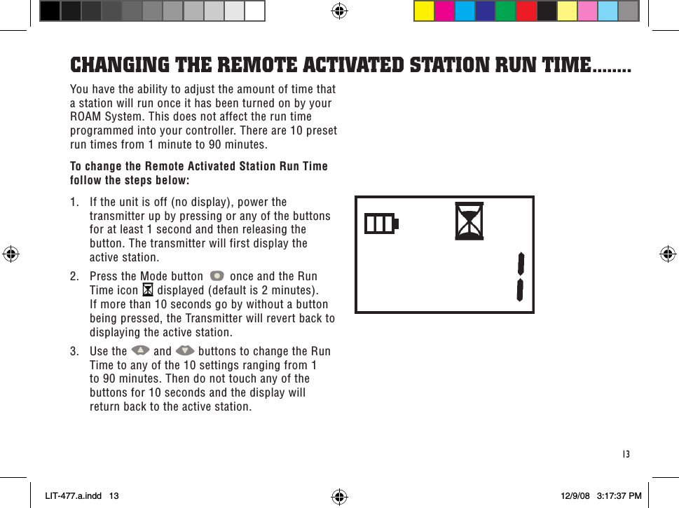
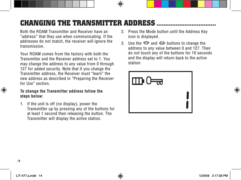
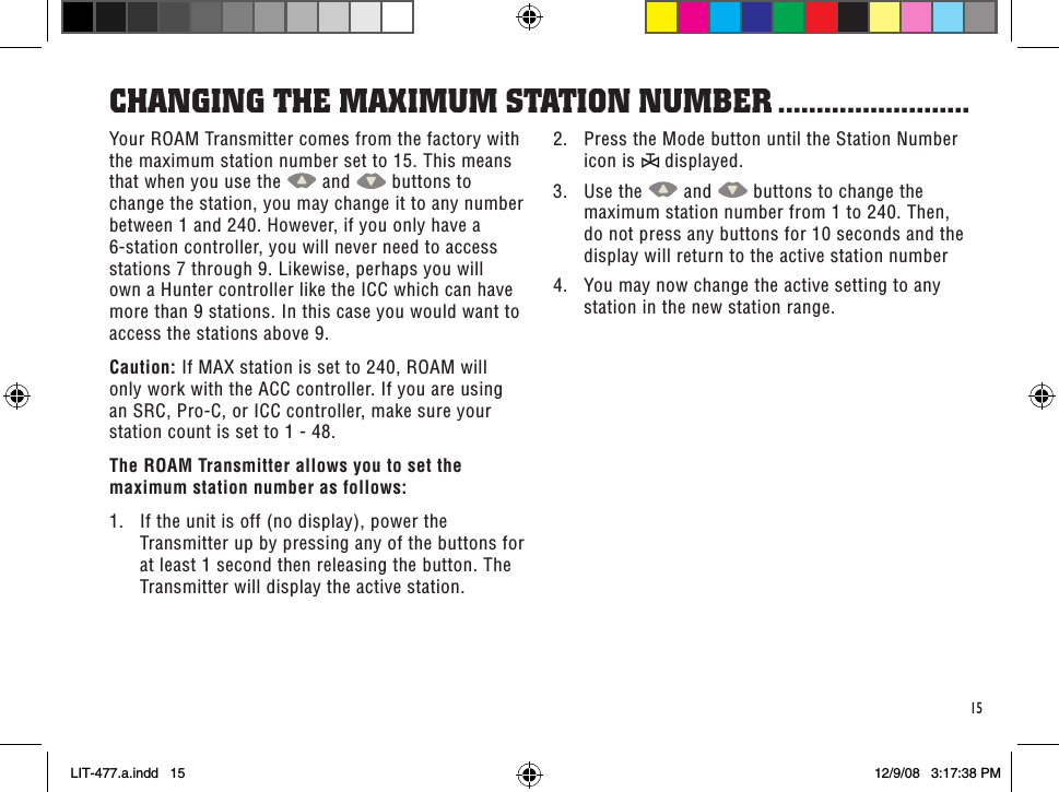
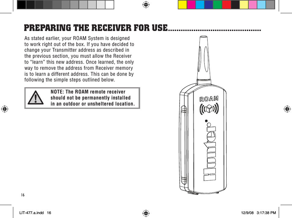
User Manual
Discussion / Help
Navigation