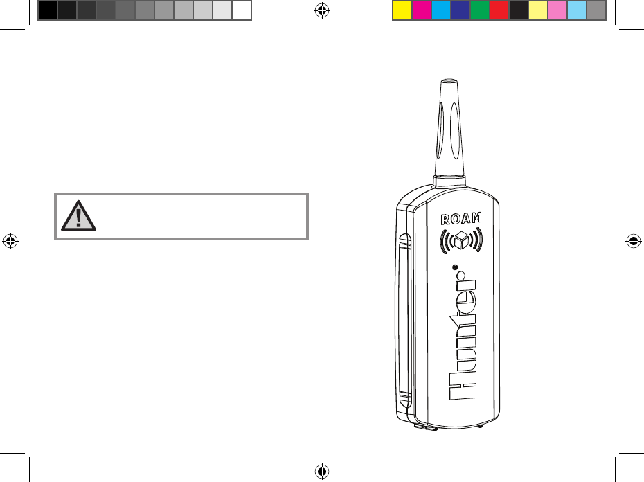
Hunter RMT Remote Control -- Transmitter User Manual
Hunter Industries Inc Remote Control -- Transmitter Users Manual
Hunter >
Users Manual
Owner’s Manual and
Installation Instructions
For use with Hunter Controllers
with SmartPort® Connection
Residential/Light Commercial
Remote Control System
Owner’s Manual and
Installation Instructions
For use with Hunter Controllers
with SmartPort® Connection
Residential/Light Commercial
Remote Control System
LIT-477.a.indd 1 12/9/08 3:17:23 PM

LIT-477.a.indd 2 12/9/08 3:17:24 PM

INTRODUCTION ........................................................................................................................................ 1
ROAM COMPONENTS ............................................................................................................................... 2
WIRING HARNESS/SMARTPORT® CONNECTION KIT .................................................................................. 5
INSTALLING THE ROAM REMOTE WIRING HARNESS ................................................................................. 6
WIRING THE SMARTPORT® TO HUNTER CONTROLLERS ............................................................................ 7
TYPICAL INSTALLATION ........................................................................................................................... 8
MAXIMIZING OPERATING RANGE .............................................................................................................. 9
EXTENDING WIRING ON SMARTPORT® HARNESS ..................................................................................... 1 0
PREPARING THE TRANSMITTER FOR USE ................................................................................................. 1 1
INSTALLING THE TRANSMITTER BATTERY ................................................................................................ 1 2
CHANGING THE REMOTE ACTIVATED STATION RUN TIME .......................................................................... 1 3
CHANGING THE TRANSMITTER ADDRESS ................................................................................................. 1 4
Table of ConTenTs ........................................................................
LIT-477.a.indd 3 12/9/08 3:17:24 PM

CHANGING THE MAXIMUM STATION NUMBER .......................................................................................... 1 5
PREPARING THE RECEIVER FOR USE ........................................................................................................ 1 6
CHANGING THE RECEIVER ADDRESS ........................................................................................................ 1 7
ACTIVATING A STATION WITH THE ROAM REMOTE CONTROL SYSTEM ...................................................... 1 8
A WORD ABOUT RANGE ........................................................................................................................... 1 9
TROUBLESHOOTING GUIDE ...................................................................................................................... 2 0
SPECIFICATIONS ...................................................................................................................................... 2 1
NOTES ..................................................................................................................................................... 2 2
FCC COMPLIANCE NOTICE ........................................................................................................................ 2 4
Table of ConTenTs (ConTinued) ..............................................
LIT-477.a.indd 4 12/9/08 3:17:24 PM
1
Finally, there’s no need to walk back to the controller to start and stop a manual watering cycle when doing
maintenance or repair work on your irrigation system. Finally, winterization can be done quickly and easily
with one worker instead of two. Finally no more going back to the garage to start or stop a manual irrigation
cycle.
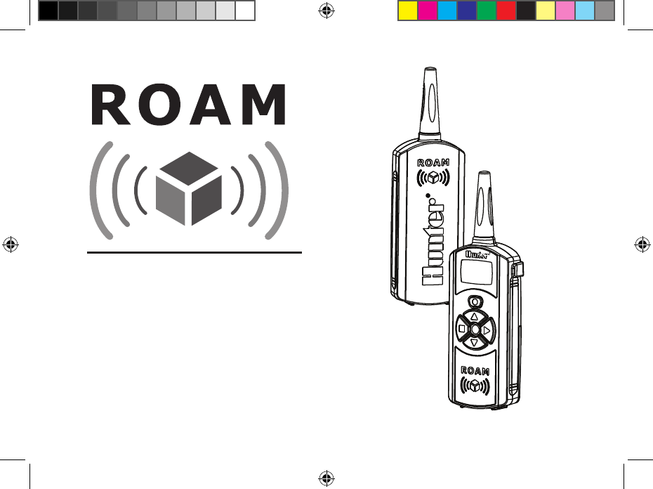
Hunter is pleased to introduce the ROAM Remote Control System for use with Hunter controllers with
SmartPort® connection. The ROAM can offer you features other remotes can’t, at a price you can afford.
The ROAM transmitter is made of sturdy ABS. It features a large LCD and simple push button operation. Don’t
let its size fool you–while it’s small enough to fit in your shirt pocket, it has an open field range of up to 1000
feet.
The large LCD display and simple four-button control make the ROAM a snap to use. Simply press the
or keys to display the station or program you want to turn on or off, then press the or button–what
could be easier? Don’t worry about forgetting to turn off the ROAM. After several minutes of inactivity the
unit turns itself off to extend battery life. Then, the unit can be turned back on by touching any button. Four
AAA alkaline batteries will last an entire season for a contractor, and years for a homeowner.
We believe the ROAM is the simplest remote control available. It is so easy to use that you will need this
booklet very little after installation. If you do have a question, keep this in a safe place for easy reference.
Congratulations–your life just got a little easier!
inTRoduCTion ..................................................................................
LIT-477.a.indd 1 12/9/08 3:17:27 PM
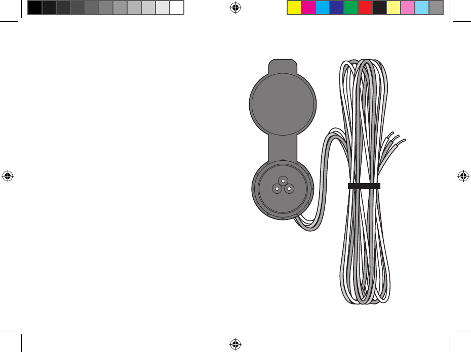
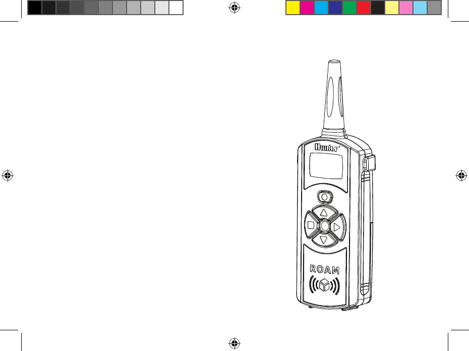
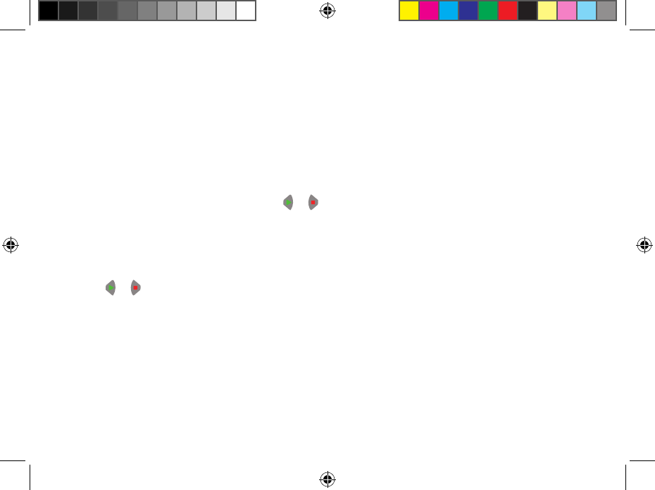
TRANSMITTER RECEIVER SmartPort®
2
RoaM CoMPonenTs ........................................................................
LIT-477.a.indd 2 12/9/08 3:17:30 PM
3
This section will give you a brief description of
the components of the ROAM. Each item will be
discussed in further detail later, however this
section can be helpful in getting acquainted with the
Transmitter, Receiver, and SmartPort®.
TRANSMITTER
A. LCD Display
1. Run Time – Indicates the station run time
is being set when flashing.
2. Transmit – Indicates that the transmitter
is transmitting the programmed data to the
receiver.
3. Station Number – Indicates station
number (1 to 240).
On – Indicates Transmitter is turning on a
particular station.
Off – Indicates Transmitter is turning off a
particular station.
PA, PB, PC – Indicates program selected.
4. Address – Indicates that a new address
for transmitting between the Transmitter and
the Receiver is being set.
B. Control Buttons
5. – Increases the selected functions.
6. – Decreases the selected functions.
7. – Selects the selected functions.
8. – Cancels the selected functions.
9. – Scrolls between functions.
C. Other
9. Battery Cover – Covers compartment for four
AAA alkaline batteries.
LIT-477.a.indd 3 12/9/08 3:17:31 PM

4
RoaM CoMPonenTs (ConTinued) ..............................................
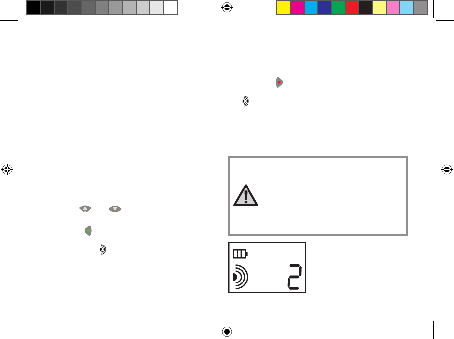
RECEIVER
10. SmartPort® Outlet (Male) – Outlet on back
of Receiver that plugs into the SmartPort
harness.
12. Antenna – Receives signals from Transmitter
from up to 1000'.
SmartPort
®
13. SmartPort Outlet (Female) – Outlet on front
of SmartPort® that plugs into the ROAM
Receiver or other Hunter product.
14. Rubber Cover – Protects SmartPort from dirt
and weather.
15. Control Wires – Red, white, and blue wires
that connect to the terminal strip area of the
controller.
LIT-477.a.indd 4 12/9/08 3:17:31 PM
5
To utilize the ROAM Remote Control System, your
controller must be equipped with the SmartPort
wiring/harness connection kit. This wiring harness
provides the connection port where the ROAM
receiver is attached.
The SmartPort wiring harness is included with the
purchase of the ROAM. Additional SmartPorts may
be purchased separately to allow you to utilize the
transmitter and receiver with additional Hunter
controllers.
WiRinG HaRness/sMaRTPoRT® ConneCTion KiT ................
LIT-477.a.indd 5 12/9/08 3:17:32 PM
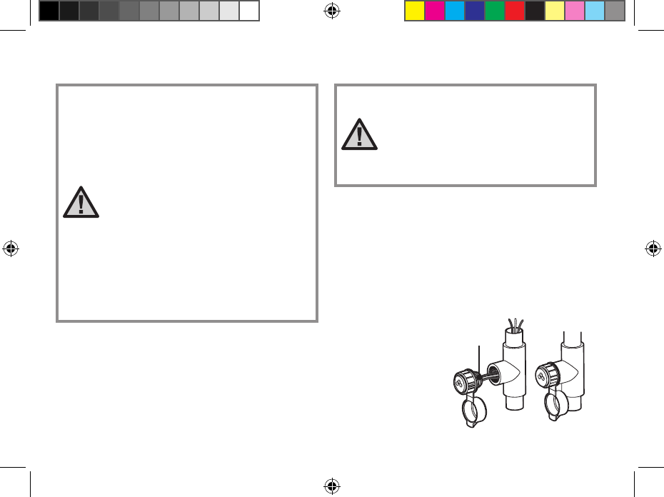
1/2" Thread
To Controller
Pre-assembled Assembled
6
Figure 1
1. Install a ½" female threaded “Tee” in the field
wiring conduit approximately 12" from the
controller.
2. Feed the red, white, and blue wires of the
SmartPort through the base of the “Tee” and into
the controller wiring compartment as shown in
Figure 1.
insTallinG THe RoaM ReMoTe WiRinG HaRness ...............
NOTE: Any extension of the wires
provided with the standard wiring
harness may result in an error
message on the controller display
and possible malfunction of the
remote due to radio interference. In
some situations, lengthening of the
standard harness may work fine, in
others it may not work at all (it is
site specific). In either case, it is
recommended that installations where
the SmartPort® outlet will be located
more than 5 feet from the controller
that the installation be done using the
shielded cable wiring harness (ROAM-
SCWH) to minimize the possible
effects of electrical noise.
NOTE: While the SmartPort has a
protective cover to allow for outdoor
installation, the ROAM Receiver
should only be used on a temporary
basis, as the Receiver is not
designated for permanent outdoor
mounting.
3. Screw the SmartPort housing into the “Tee”
(or other fitting) as shown in Figure 1.
4. Route wiring harness into controller housing.
Attach the red wire to the first AC screw slot.
Attach the white wire to the other AC screw slot,
and attach the blue wire to the R (or REM on
some controllers) as shown in Figure 2.
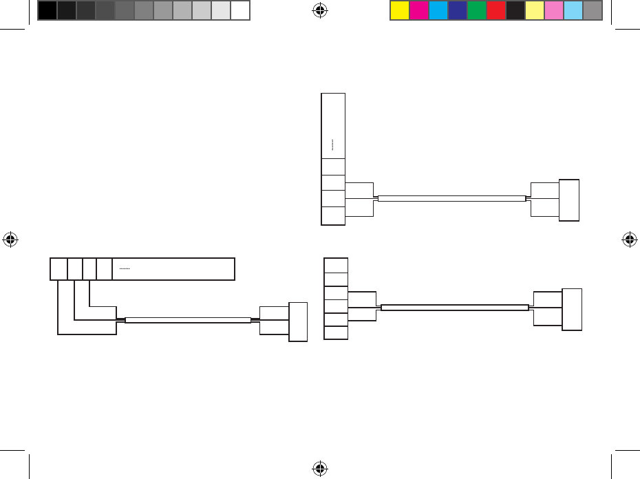
LIT-477.a.indd 6 12/9/08 3:17:32 PM
Red
Blue
White
Blue
White
Red
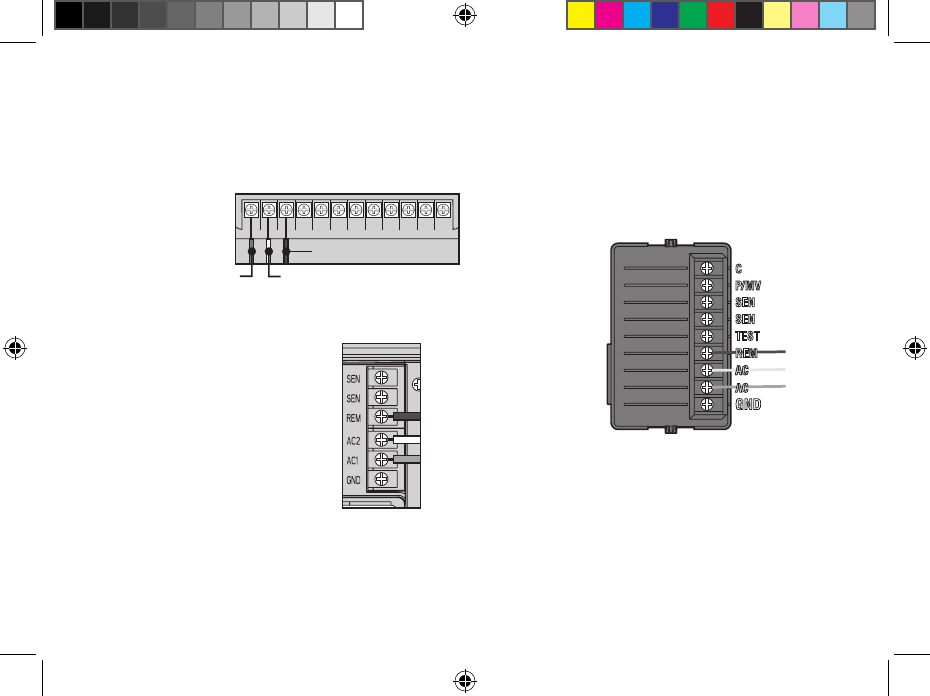
AC AC RRSCMV 123456
White
Blue
Red
7
SRC Controller SmartPort Installation
Access the terminal strip area and attach the red wire
to the left AC screw slot, attach the white wire to the
next AC screw
slot and attach
the blue wire
to the screw
slot marked
“R”.
Pro-C Controller SmartPort Installation
Access the terminal strip area
on the main module and attach
the red wire to the bottom most
AC screw slot, attach the white
wire to the upper AC screw slot
and attach the blue wire to the
screw slot marked “REM”.
ICC Controller SmartPort Installation
Access the terminal strip area on the power module
and attach the red wire to the bottom most AC screw
slot, attach the white wire to the upper AC screw slot
and attach the blue wire to the screw slot marked
“REM”.
WiRinG THe sMaRTPoRT® To HunTeR ConTRolleRs .........
LIT-477.a.indd 7 12/9/08 3:17:33 PM
Hunter
Controller
Field Wiring
Conduit
Receiver
Field Wiring
Conduit to
Valves
Transmitter
Weather Resistant
SmartPort
®
Cover
Up to 1000 ft.
8
Receiver Mounted Indoors
This installation is ideal for situations when the
ROAM system will be left permanently connected to
the controller in an indoor area.
Connection of Receiver on a Temporary Basis
from Outside of a Garage or Building
This installation is ideal for situations where a
contractor desires the ability to access and operate
a controller from outside of a locked building or
garage. However, the ROAM receiver must be
removed from the SmartPort® and the weather
resistant cap placed back on the outlet after each
use.
To Controller
TYPiCal insTallaTion ...................................................................
LIT-477.a.indd 8 12/9/08 3:17:34 PM
9
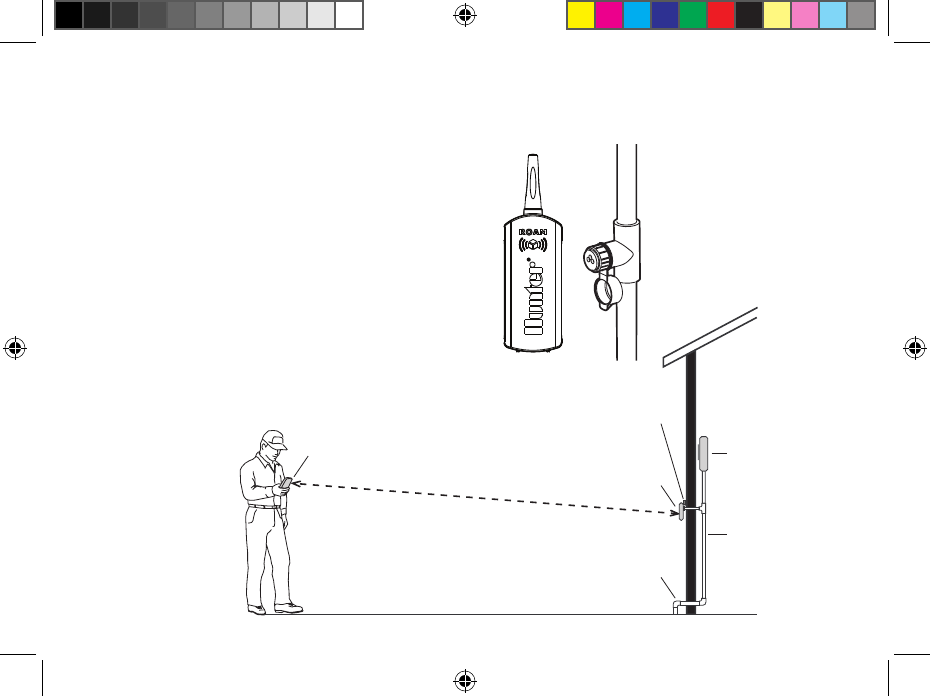
There are many factors which influence operating
range. Listed below are a few things you can do to
assure that you get maximum range possible.
1. Do not install SmartPort® near large sources of
metal such as power meters, water pipes, and
aluminum siding.
2. Do not install SmartPort in a basement or
underground location. The higher the location
the better chance of strong reception.
3. For maximum range in all directions, the receiver
should be pointed straight up (vertically). If
receiver is mounted with its antenna oriented
horizontally, reception will be very good if
transmitter is on either side of the antenna, but
very poor if it is facing either end of the receiver
antenna.
4. When operating transmitter, hold the transmitter
as vertical as possible and face in the direction
of the receiver, especially if it is several hundred
feet away.
MaXiMiZinG oPeRaTinG RanGe .................................................
NOTE: Remote is designed for
residential and small commercial
sites. Large projects such as
cemeteries and golf courses will
require a long-range remote.
LIT-477.a.indd 9 12/9/08 3:17:34 PM
HUNTER SRR-SCWH
WIRING HARNESS
SRC TERMINAL BLOCK
BLUE
WHITE
RED
BLUE
WHITE
RED
AC AC RRS
HUNTER SRR-SCWH WIRING HARNESS
BLUE
WHITE
RED
ICC TERMINAL BLOCK
BLUE
WHITE
RED
AC
AC
R
RS
HUNTER SRR-SCWH WIRING HARNESS
BLUE
WHITE
RED
PRO-C TERMINAL BLOCK
BLUE
WHITE
RED
SEN
SEN
REM
AC2
AC1
GRD
10
Use shielded cable to connect the SmartPort to the
controller if installing the connector more than 2
meters of wiring length from the controller. The
use of shielded cable will eliminate the potential for
radio interference by preventing the wire as acting
as an antenna. At no time should the SmartPort
be installed more than 15 meters away from the
controller.
For easiest installation, order a Hunter SRS-SCWH
SmartPort wiring harness with a full 7.6 meters of
shielded cable.
eXTendinG WiRinG on sMaRTPoRT® HaRness ....................
LIT-477.a.indd 10 12/9/08 3:17:35 PM
11
Your ROAM System is designed to work right out of
the box. This means that other than installing the
batteries, you may choose to skip this entire section.
However, we recommend you read it because with a
few simple steps you can customize your ROAM to
add functionality and security to your system.
PRePaRinG THe TRansMiTTeR foR use ..................................
LIT-477.a.indd 11 12/9/08 3:17:36 PM
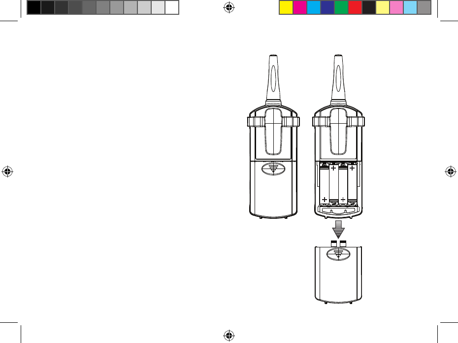
AAA
AAA
AAA
AAA
12
Your ROAM Transmitter requires four AAA alkaline
batteries. To install the batteries, slide open the
battery door on the back of the transmitter. When
changing the batteries, make sure that they are
oriented properly in the battery holder. Slide the
battery door shut.
insTallinG THe TRansMiTTeR baTTeRY ................................
LIT-477.a.indd 12 12/9/08 3:17:37 PM
13
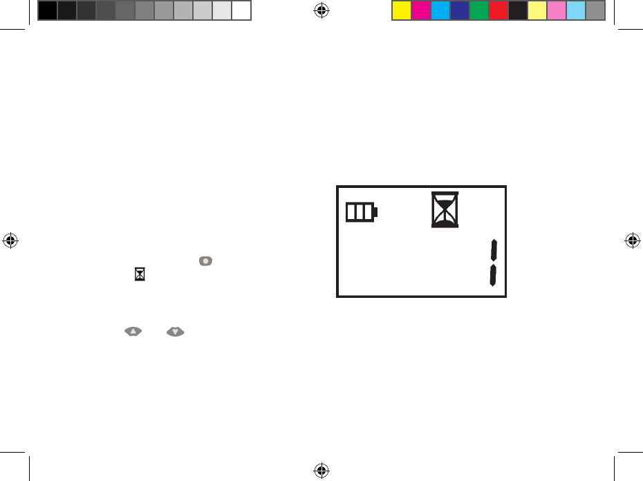
You have the ability to adjust the amount of time that
a station will run once it has been turned on by your
ROAM System. This does not affect the run time
programmed into your controller. There are 10 preset
run times from 1 minute to 90 minutes.
To change the Remote Activated Station Run Time
follow the steps below:
1. If the unit is off (no display), power the
transmitter up by pressing or any of the buttons
for at least 1 second and then releasing the
button. The transmitter will first display the
active station.
2. Press the Mode button once and the Run
Time icon displayed (default is 2 minutes).
If more than 10 seconds go by without a button
being pressed, the Transmitter will revert back to
displaying the active station.
3. Use the and buttons to change the Run
Time to any of the 10 settings ranging from 1
to 90 minutes. Then do not touch any of the
buttons for 10 seconds and the display will
return back to the active station.
CHanGinG THe ReMoTe aCTiVaTed sTaTion Run TiMe ........
LIT-477.a.indd 13 12/9/08 3:17:37 PM
14
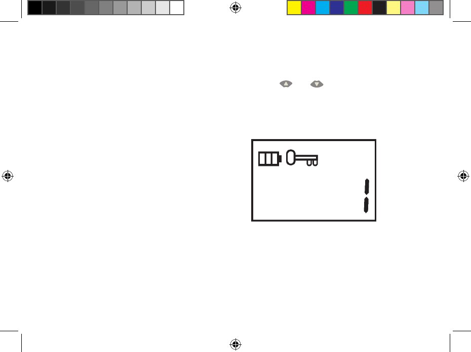
Both the ROAM Transmitter and Receiver have an
“address” that they use when communicating. If the
addresses do not match, the receiver will ignore the
transmission.
Your ROAM comes from the factory with both the
Transmitter and the Receiver address set to 1. You
may change the address to any value from 0 through
127 for added security. Note that if you change the
Transmitter address, the Receiver must “learn” the
new address as described in “Preparing the Receiver
for Use” section.
To change the Transmitter address follow the
steps below:
1. If the unit is off (no display), power the
Transmitter up by pressing any of the buttons for
at least 1 second then releasing the button. The
Transmitter will display the active station.
CHanGinG THe TRansMiTTeR addRess ..................................
2. Press the Mode button until the Address Key
icon is displayed.
3. Use the and buttons to change the
address to any value between 0 and 127. Then
do not touch any of the buttons for 10 seconds
and the display will return back to the active
station.
LIT-477.a.indd 14 12/9/08 3:17:38 PM
15
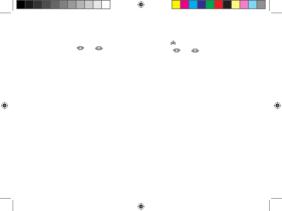
Your ROAM Transmitter comes from the factory with
the maximum station number set to 15. This means
that when you use the and buttons to
change the station, you may change it to any number
between 1 and 240. However, if you only have a
6-station controller, you will never need to access
stations 7 through 9. Likewise, perhaps you will
own a Hunter controller like the ICC which can have
more than 9 stations. In this case you would want to
access the stations above 9.
Caution: If MAX station is set to 240, ROAM will
only work with the ACC controller. If you are using
an SRC, Pro-C, or ICC controller, make sure your
station count is set to 1 - 48.
The ROAM Transmitter allows you to set the
maximum station number as follows:
1. If the unit is off (no display), power the
Transmitter up by pressing any of the buttons for
at least 1 second then releasing the button. The
Transmitter will display the active station.
CHanGinG THe MaXiMuM sTaTion nuMbeR .........................
2. Press the Mode button until the Station Number
icon is displayed.
3. Use the and buttons to change the
maximum station number from 1 to 240. Then,
do not press any buttons for 10 seconds and the
display will return to the active station number
4. You may now change the active setting to any
station in the new station range.
LIT-477.a.indd 15 12/9/08 3:17:38 PM
16
As stated earlier, your ROAM System is designed
to work right out of the box. If you have decided to
change your Transmitter address as described in
the previous section, you must allow the Receiver
to “learn” this new address. Once learned, the only
way to remove the address from Receiver memory
is to learn a different address. This can be done by
following the simple steps outlined below.
PRePaRinG THe ReCeiVeR foR use ............................................
NOTE: The ROAM remote receiver
should not be permanently installed
in an outdoor or unsheltered location.
LIT-477.a.indd 16 12/9/08 3:17:38 PM
17
1. Before setting the receiver address, make sure
that the transmitter address is set to the address
you would like to use.
2. Plug the receiver into a SmartPort® connected
to a powered controller. When this is done, the
receiver will beep 4 times.
3. Once the receiver beeps 4 times, you have
approximately 10 seconds to send the new
address to the receiver. Press either the or
button on your transmitter to connect.
4. The receiver will beep 4 additional times
indicating that it has learned the new transmitter
address and will respond only to that address
from this point on. If 10 seconds expire before
the or button is pressed, the receiver will
beep once and retain its original address.
CHanGinG THe ReCeiVeR addRess ............................................
LIT-477.a.indd 17 12/9/08 3:17:39 PM
18
The ROAM System will allow you to remotely turn
on and off any station on your Hunter controller with
the press of a button. Once on, the station will run
for the run time you have designated in the remote.
To remotely activate a station or program follow the
steps below:
1. Plug the receiver into a SmartPort® that is
connected to a powered controller. The receiver
will beep 4 times followed by a 10-second pause
and a single beep.
2. If your transmitter is not on (no display), press
any button for at least one second and release.
The Transmitter will display the active station.
3. Use the and buttons to display the
station or program you would like to start.
4. Press the button to start the station or
program. The Transmitter will display the
Transmit icon . If you are near the receiver,
you will hear it beep 2 times. This indicates that
the Receiver has received the command.
aCTiVaTinG a sTaTion WiTH THe RoaM ReMoTe
ConTRol sYsTeM .............................................................................
5. Press the button to turn off any station that
is on. The display will show the Transmit icon
and receiver will beep again twice. The ROAM
System is designed to turn on one station at a
time (unless you activate a program). Therefore,
turning a station on while another station is
operating will cause the operating station to turn
off.
NOTE: The ROAM remote can activate
any station on the controller whether
the controller dial is in the “SYSTEM
OFF”, “RUN” or “RUN/BYPASS
SENSOR” modes. If a sensor device
has been wired to the controller, the
ROAM remote will NOT override the
sensor for manual operation.
LIT-477.a.indd 18 12/9/08 3:17:39 PM

19
The ROAM Transmitter has been designed to
transmit the maximum power allowed by the FCC.
Furthermore, it has special circuitry to assure that
this maximum output power is maintained until just
before the battery goes dead. Other transmitters emit
less and less power as the battery wears down. And
our special SmartPort® wiring harness is designed
to keep interfering signals at a minimum, especially
with the addition of Hunter shielded cable. The
Receiver employs a reception method far superior
to that used in a typical garage door opener or car
alarm.
The ROAM has been designed to give you simple,
reliable operation for many years.
There are many claims being made about the range
of various remote control systems, whether they
be for auto alarms, garage doors, or irrigation
systems for that matter. The published range for
the ROAM System is up to 1000 feet. Most users
will achieve this range or more, but a few may not.
It is the attempt of this section to educate the user
about those factors that influence operating range.
We believe that we have achieved the maximum
performance available on this frequency. Here’s
why…
The range of any remote control system is dependent
on many factors. These include the terrain at a
particular site, obstructions such as buildings
and walls, the strength of the various interfering
signals, the sensitivity of the Receiver, the ability of
the Receiver to reject “unwanted” signals, and the
strength of the Transmitter. Since it is impossible
to control the obstructions, terrain at a site, and the
strength of interfering signals, it is impossible to
guarantee an operating range under all conditions.
However, we have done everything under our control
to maximize the operating range of this system.
a WoRd abouT RanGe ....................................................................
LIT-477.a.indd 19 12/9/08 3:17:39 PM
20
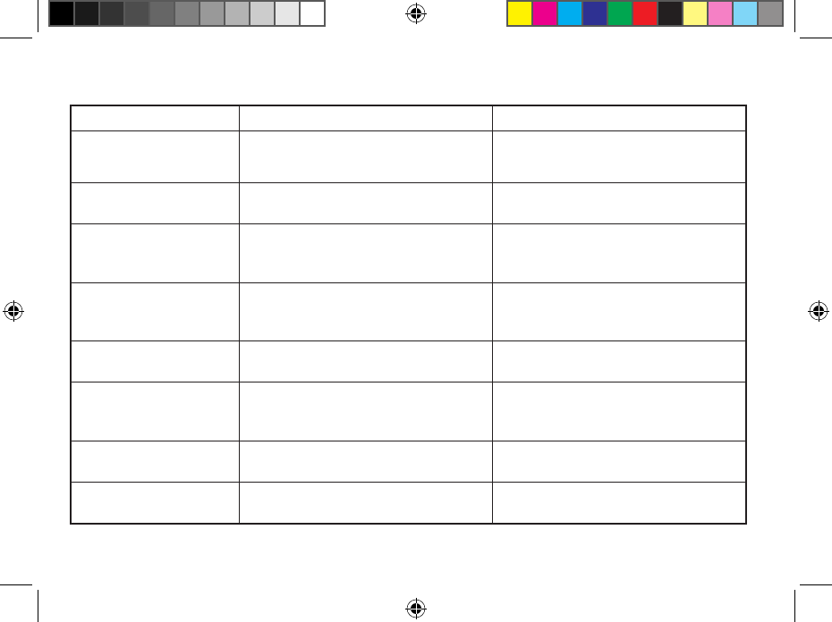
TRoublesHooTinG Guide .............................................................
PROBLEM CAUSES SOLUTIONS
Transmitter display is blank. Transmitter is off.
Batteries are dead.
Press any button for 1 second.
Can’t access all the desired
stations on the Transmitter.
Maximum station number is set wrong. See “Changing the Maximum Station.”
Receiver doesn’t beep 4 times
after plugging it in.
SmartPort® is not connected properly.
Controller has no power.
Recheck SmartPort wiring.
Check controller power.
Receiver won’t respond to
Transmitter.
Receiver and Transmitter address don’t match Relearn address at receiver.
Transmitter display stays on. Transmitter will turn off automatically. Wait approximately 5 minutes without pressing any
buttons. Transmitter will “fall asleep.”
“ERR” message in controller
display when controller is in the
run position.
SmartPort wiring leads have been extended and are
receiving radio interference.
Replace lengthened wire with shielded cable to
prohibit radio interference. Use Hunter ROAM-SCWH.
See “Extending Wiring on SmartPort Harness.”
Receiver does not receive signal
from remote held at close range.
Mismatch of addresses in transmitter and receiver. Reset address of receiver.
Remote has short range
(i.e. less than 100 feet).
Check for interference causes. See “Maximizing Operating Range.”
LIT-477.a.indd 20 12/9/08 3:17:39 PM
sPeCifiCaTions ................................................................................
21
Default Settings
• Address=1
• Numberofstations=15
(may be varied from 1-240)
• RunTime:2minutes
Dimensions
Transmitter: Receiver:
• Height:7" • Height:7"
• Width:2¼" • Width:2¼"
• Depth:1¼" • Depth:1"
*See “A Word About Range” for more information.
Operating Specifications
• Addressrange:0-127
• Maximumstationssupported:240
• RunTime:10settingsfrom1-90minutes
• Range:upto1,000feet*
Electrical Specifications
• PowerSourceTransmitter:
(4) AAA Alkaline Batteries
• PowerSourceReceiver:
24VAC, 0.010 Amps
• Receivertype:Superheterodyne
• SystemOperatingfrequency:433.925MHZ
LIT-477.a.indd 21 12/9/08 3:17:39 PM

fCC noTiCe ..........................................................................................
22
Transmitter FCC ID:M3URMT
This device complies with FCC rules Part 15. Operation is subject to the following two conditions:
1. This device may not cause harmful interference and
2. This device must accept any interference received, including interference that may cause undesired operation.
This equipment has been tested and found to comply with the limits for class B digital devices, pursuant to part 15 of the FCC
Rules. These limits are designed to provide reasonable protection against harmful interference in a residential installation.
This equipment generates, uses, and can radiate radio frequency energy and if not installed and used in accordance with the
instructions, may cause harmful interference to radio communications. However, there is no guarantee that interference will
not occur in a particular installation. If this equipment does cause harmful interference to radio or television reception, which
can be determined by turning the equipment on and off, the user is encouraged to try to correct the interference by one or
more of the following measures:
•Reorientorrelocatethereceivingantenna
•Increasetheseparationbetweentheequipmentandthereceiver
•Connecttheequipmenttoanoutletonacircuitdifferentfromthattowhichthereceiverisconnected
•Consultthedealeroranexperiencedradio/TVtechnicianforhelp
The user is cautioned that changes and modifications made to the equipment without the approval of the manufacturer could
void the user’s authority to operate this equipment.
LIT-477.a.indd 22 12/9/08 3:17:39 PM
fCC deClaRaTion of ConfoRMiTY ............................................
TRADE NAME Remote Control Device
MODEL NUMBER ROAM-R
COMPLIANCE TEST REPORT NUMBER B80912D1
COMPLIANCE TEST REPORT DATE Sept 12th, 2008
RESPONSIBLE PARTY Hunter Industries Incorporated
ADDRESS 1940 Diamond St, San Marcos CA 92078
TELEPHONE 760-744-5240
This equipment has been tested and found to comply with the limits for class B digital devices, pursuant to part 15 of the FCC
Rules. These limits are designed to provide reasonable protection against harmful interference in a residential installation.
This equipment generates, uses, and can radiate radio frequency energy and if not installed and used in accordance with the
instructions, may cause harmful interference to radio communications. However, there is no guarantee that interference will
not occur in a particular installation.
If this equipment does cause harmful interference to radio or television reception, please refer to you user’s manual for
instructions on correcting the problem.
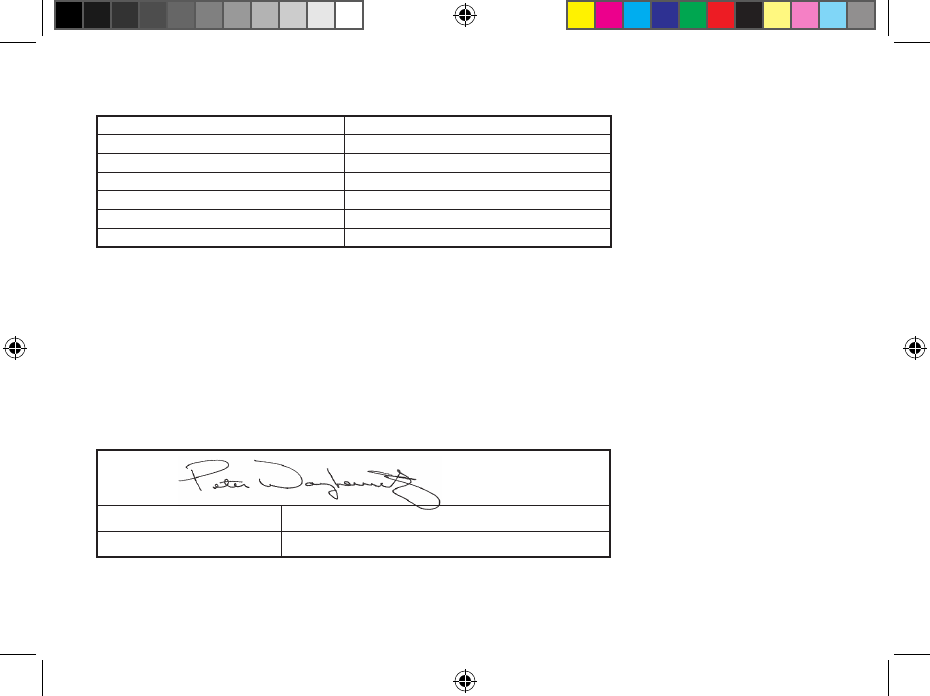
I the undersigned, hereby declare that the equipment specified above conforms to the above requirements.
Signature:
Place: San Marcos, CA Full Name: Peter Woytowitz
Date: September 25, 2008 Position: Engineering Manager
LIT-477.a.indd 23 12/9/08 3:17:40 PM
Transmitter - IC:2772A-RMT
Receiver - IC:2772A-RMR
Operation is subject to the following two conditions:
This device may not cause harmful interference and
This device must accept any interference received, including interference that may cause undesired operation.
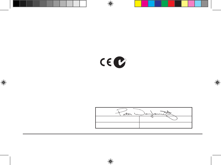
Ce & ausTRalia noTiCe ..............................................
Hunter Industries hereby declares that this remote control device is in compliance with the essential requirements and other relevant
provisions of Directive 1999/5/CE.
Declaration of Conformity: We, Hunter Industries Incorporated, 1940 Diamond Street, San Marcos, CA 92078, declare under our own
responsibility that the ROAM remote control product, model numbers ROAM-TR and ROAM-R, to which this declaration refers, conforms
with the relevant standards:
Emissions: ETSI EN 300 220-1 V2.1.1
ETSI EN 300 220-2 V2.1.1
ETSI EN 301 489-1 (per EN55022)
EN 61000-3-2
EN61000-3-3
indusTRY of Canada noTiCe ......................................................
Immunity: ETSI EN 301 489-1 V1.4.1
(per IEC61000-4-2 through IEC61000-4-6,
and IEC61000-4-11)
Signature:
Place: San Marcos, CA Full Name: Peter Woytowitz
Date: September 25, 2008 Position: Engineering Manager
Hunter Industries Incorporated • The Irrigation Innovators © 2008 Hunter Industries Incorporated
1940 Diamond Street • San Marcos, California 92078
www.HunterIndustries.com
LIT-477 12/08
LIT-477.a.indd 24 12/9/08 3:17:40 PM