Hunter WFSR Wireless Flow Sensor - Receiver User Manual Owner Manual
Hunter Industries Inc Wireless Flow Sensor - Receiver Owner Manual
UserManual.wiki
>
Hunter
>
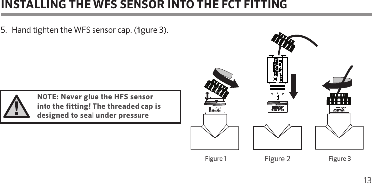
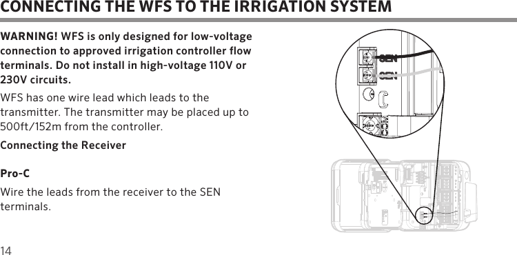
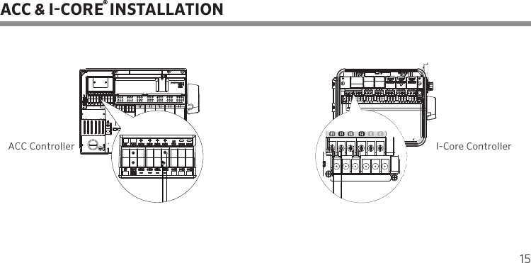
WFSR User Manual
Owner Manual
Navigation menu
Upload a User Manual
Namespaces
Wiki Guide
HTML
PDF
Info
Views
User Manual
Discussion / Help
Navigation