Hunter WFSR Wireless Flow Sensor - Receiver User Manual Owner Manual
Hunter Industries Inc Wireless Flow Sensor - Receiver Owner Manual
Hunter >
Owner Manual

WIRELESSFLOWSENSOR
WFS
Hunter Wireless-Flow-Sync
Owner’s Manual and Installation Guide
Wireless Flow Sensor for Use with Compatible Hunter Controllers

TABLE OF CONTENTS
INTRODUCTION ................................................................................................................3
WFS COMPONENTS ........................................................................................................4
SYSTEM OVERVIEW AND WFS OPERATION .................................................................6
INSTALLING THE WFS SENSOR & FCT TEE ...................................................................8
INSTALLING THE WFS SENSOR INTO THE FCT FITTING ............................................12
CONNECTING THE WFS TO THE IRRIGATION SYSTEM .............................................14
SYSTEM CONSIDERATIONS ............................................................................................17
TROUBLESHOOTING GUIDE ..........................................................................................20
SPECIFICATIONS AND CALIBRATION ............................................................................ 23

3
The Hunter WFS allows flow-capable
controllers, such as the Hunter ACC and I-Core,
to monitor actual flow in irrigation systems.
With proper setup at the controller, this allows
the controller to record and report actual flow
in liters or gallons. Flow learning controllers can
also use WFS to learn typical flow for each zone
of irrigation, and monitor during watering for
high and low flow conditions.
WFS equips controllers to respond on
their own to incorrect system performance,
preventing damage to landscape and wasted
water resources.
INTRODUCTION
4
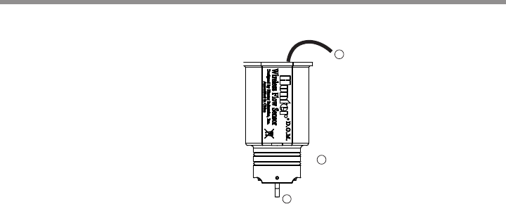
This section will give you a brief overview
of some of the components of the
Wireless-Flow-Sync system.
1. Impeller: Rotates when ow is occurring
2. O-rings:
Provides sealing of sensor in
sensor body
3. Wire:
Black wire connects to the sensor
transmitter
WFS COMPONENTS
2
3
1
5
3
4
2
1
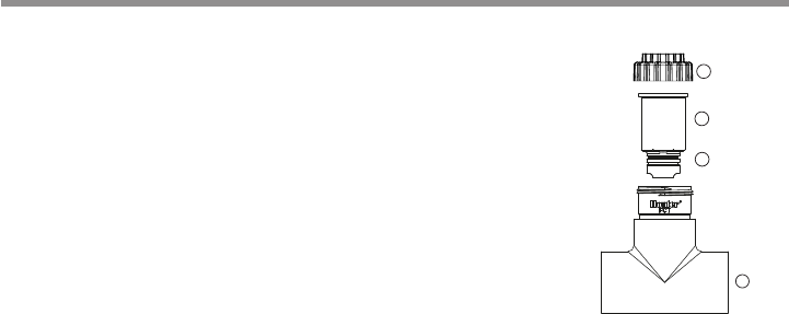
1. Flow-Sync Tee: The Tee is installed into the irrigation system and houses the WFS
2. O-rings:
Provides sealing of plug in sensor body
3. Plug:
(replace with WFS at Installation)
4. Cap:
To seal plug to Flow-Sync-Tee
WFS TEE ASSEMBLY

6
The WFS is typically installed near the point of
connection, in an appropriately-sized FCT Tee.
The WFS transmitter can connect to a host con-
troller up to 500ft/152M away.
WFS sensors operate with an impeller
positioned in the flow through the pipes.
As the impeller turns, pulses are generated to
the controller, which converts them to gallons or
liters, depending on the Units of Measurement
selection in the controller.
WFS Sensor is a reporting device, and does not
respond to flow situations on its own. WFS is
almost always installed in conjunction with a
Master Valve, which can stop flow in a damaged
pipe when high flow conditions are detected.
SYSTEM OVERVIEW AND WFS OPERATION
7
WFS ICORE
WIRING

8
INSTALLING THE WFS SENSOR AND FCT TEE
HFS FCT Tee Fitting Models (All tees are glue/slip type fittings)
Model Material Diameter (US) Diameter (mm)
FCT 100 Schedule 40 (white) 1" 25 mm
FCT 150 Schedule 40 (white) 1.5" 37 mm
FCT 158 Schedule 80 (gray) 1.5" 37 mm
FCT 200 Schedule 40 (white) 2" 50 mm
FCT 208 Schedule 80 (gray) 2" 50 mm
FCT 300 Schedule 40 (white) 3" 75 mm
FCT 308 Schedule 80 (gray) 3" 75 mm
FCT 400 Schedule 40 (white) 4" 100 mm
BSP Adapters
Diameter (mm) Model
25 mm 795700
37 mm 795800
50 mm 241400
75 mm 477800
The WFS Sensor is designed to install within an
FCT tee fitting, sized for the pipe in which it will
be installed.
For international applications, optional slip-BSP
adapters are available separately for sizes up to
75 mm.

9
Install the FCT tee fitting first, then install the
WFS Sensor into the fitting.
Observe the following general rules when choosing
the sensor location and preparing to install:
• Flush system with plug in place before
installing the WFS sensor, to prevent damage
to the impeller.
• Always install WFS together with a Master
Valve, to provide overflow protection.
• Install the WFS and Master Valve as
near the point of connection to the water
supply as possible.
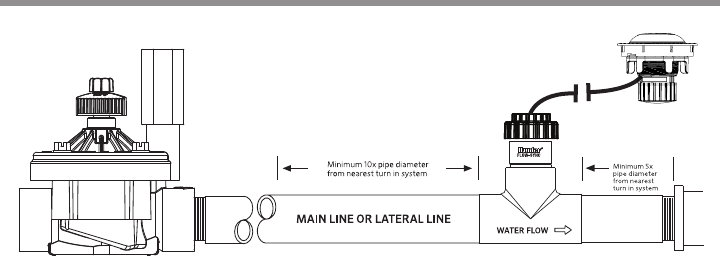
• WFS requires a section of straight
pipe on either side of the tee fitting to provide
accurate measurement of flow. Tees, ells,
and other fittings cause turbulence which
affects accuracy.
• There must be a length of straight pipe at least
10 times the diameter of the pipe upstream
from the WFS (toward the water supply).
• There must be a length of straight pipe at least
5 times the diameter of the pipe in the down-
stream direction (toward the sprinklers).
INSTALLATION

10
• Example: FCT-200 is installed in a 2”/50 mm
diameter pipe. The tee should have 20”/50
cm of straight pipe upstream, and 10”/25 cm
straight pipe downstream.
• Install the WFS and FCT assembly in a sturdy
irrigation valve box.
• WFS has an impeller which will turn in the flow
of water. If the water source is not a public
water supply, add a filter upstream from the
Master Valve and WFS to protect the impeller
from rocks or stones, which may damage the
impeller.
The FCT tee fitting is designed for glue (“slip”)
connection. Use approved PVC solvent-welding
glue to install either threaded fittings, or directly
into the irrigation pipe if desired.
Metric thread adapters are available and are
listed in this manual on page 8.
Avoid excess glue when attaching
fittings. Uncured blobs of excess glue
on the fitting’s interior can interfere
with paddlewheel operation.
11
EXAMPLE OF INSTALL
*NOTE: Not to scale.

12
The FCT tee fitting comes with a plug that allows
for installation of the FCT into the irrigation
system prior to installing the Sensor. This allows
the FCT tee to be installed separately from the
sensor and prevents damage to the sensor during
installation of the body.
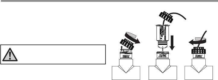
NOTE: Do not attempt to remove the
sensor plug or sensor while the system
is under pressure
To install the sensor into the body:
1.
Turn the system pressure o.
2.
Unscrew the cap from the top of the FCT (gure 1).
3.
Use pliers or a screwdriver and carefully pry the
plug from the FCT tee.
4.
Insert the sensor into the FCT. The sensor has a
at side that engages with a at on the inside of
the sensor body (gure 2).
INSTALLING THE WFS SENSOR INTO THE FCT FITTING
13
Figure 1
Figure 1 Figure 3
Figure 2
Figure 2
5. Hand tighten the WFS sensor cap. (gure 3).
NOTE: Never glue the HFS sensor
into the fitting! The threaded cap is
designed to seal under pressure
INSTALLING THE WFS SENSOR INTO THE FCT FITTING
14
CONNECTING THE WFS TO THE IRRIGATION SYSTEM
WARNING! WFS is only designed for low-voltage
connection to approved irrigation controller flow
terminals. Do not install in high-voltage 110V or
230V circuits.
WFS has one wire lead which leads to the
transmitter. The transmitter may be placed up to
500ft/152m from the controller.
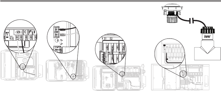
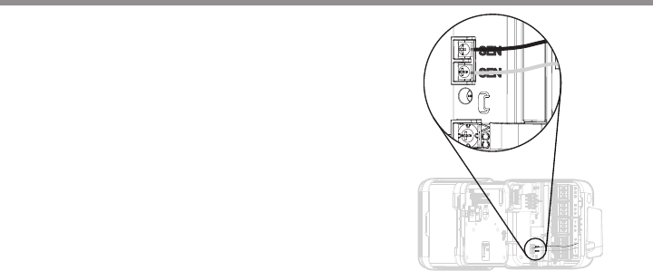
Connecting the Receiver
Pro-C
Wire the leads from the receiver to the SEN
terminals.
15
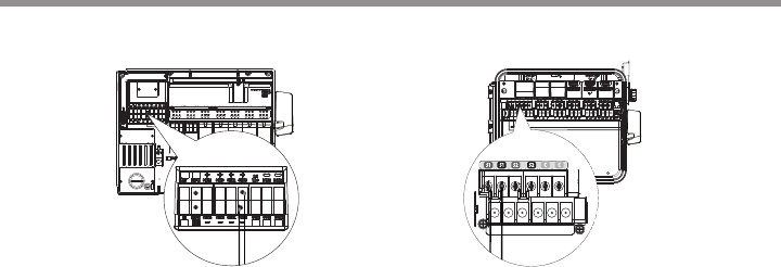
ACC & ICORE
INSTALLATION
Use terminals S1 or S2
ACC Controller I-Core Controller

Proper irrigation system design and operation
assures optimum performance of the WFS in
monitoring for potential high flow conditions.
WFS is primarily designed to shut off the irriga-
tion system in the event of a catastrophic system
failure such as a main line or lateral line break.
However, depending upon the design of the
irrigation system, the WFS can offer increased
protection when components such as sprays or
rotors are damaged or removed due to vandal-
ism. The following may be helpful in making your
WFS operate at its optimum level.
16

17
SYSTEM CONSIDERATIONS
Working With WFS
Hunter flow-capable controllers are designed
to measure and record actual flow, shut off
irrigation when a high flow condition occurs, and
identify which stations caused the condition.
The controller’s Learn mode samples each station
individually, and learns a typical flow for each
station in the system. During actual irrigation,
the flow can be observed at the controller. Actual
flows are recorded and stored in the controller
facepack. The ACC or I-Core controller will also
compare actual flows to the estimated total of all
active stations, to see if there is an unacceptable
difference, indicating a leak or break.
Consult the controller documentation closely for
setup and operation of flow monitoring. It is
vital to set the correct pipe size, so that the
controller interprets the flow data correctly. It is
also important to set adequate overage amounts
(minimum is 15% over normal) and delays
(default is one minute) to prevent false alarms.

18
Mainline Pressure Fluctuation
Some water sources may have varying pressure
depending upon the demand for water upstream
of the point of connection. During times of heavy
demand, system pressure through the mainline
may drop.
This is why the flow limit percentage and delay
periods (set in the controller) are important,
as false alarms lead to a lack of confidence in
the system.
Additionally, excess air in irrigation piping causes
the WFS impeller to spin freely during
station startup, which may cause temporarily
high readings. This problem may be reduced by
installing check valves in the system, and by
setting the alarm delay values to prevent
premature alarms.

19
Proper System Maintenance and Operation
It is important that your irrigation system
be maintained and is functioning properly for
optimum performance. Check your irrigation
system for any broken components or leaks
also, making sure that all sprinklers are operating
within the pressure ranges recommended by
the manufacturer.

20
Hunter controllers equipped with flow terminals
will have approximately 20 VDC present on the
flow sensor terminals, with no flow input.
When flow begins, the voltage will pulse. On a
standard voltmeter, the voltage will appear to
drop, or pulsate. On voltmeters equipped with a
frequency counter, the pulse frequency can be
measured in Hz.

21
TROUBLESHOOTING GUIDE
Problem Cause Solution
WFS not reading Water shut o Verify that no isolation valves are closed, and
that the water source is on.
Controller not congured Check controller ow sensor setup. Enter
sensor size (and location, for sensor decoders)
and other sensor information as required.
Damaged sensor- Impeller damage
(debris in water) or WFS
electronics damage (lightning)
Replace sensor.

Problem Cause Solution
WFS not reading correctly Controller congured incorrectly Set correct ow sensor size and
type at controller.
Turbulent ow at sensor Insure that straight pipe is on either
side of ow meter.
Frequent false alarms Station settings too sensitive Increase overow percentage (and
underow if available).
Wide range of ows for a single
station
Increase overow and underow
percentages, and delay interval.
22
TROUBLESHOOTING

Flow Range
Flow-Sync
Sensor
Diameter
Operating Range (Gpm)
Minimum
*
Suggested Maximum**
1" 2 17
1½" 5 35
2" 10 55
3" 28 120
4" 34 195
* Minimum recommended ow for the highest ow zone for
your system
** Good design practice dictates the maximum ow not to
exceed 5/sec. Suggested maximum ow is based upon
Class 200 IPS plastic pipe
Operating Specications
Temperature Pressures Humidity
0 to 140ºF/60ºC up to 200 psi/13.7 bar up to 100%
SPECIFICATIONS
23

Maximum Distance Between WFS Transmitter and Receiver 500ft/152m
Dimensions
FCT Tee Fitting Height Width Length Straight Pipe
upstream (Ø x 10)
Straight Pipe
downstream (Ø x 5)
FCT 100 4.8″/12 cm 2.3"/6 cm 4.5"/11 cm 10"/25 cm 5"/13 cm
FCT 150 5.4″/14 cm 2.3"/6 cm 4.6"/12 cm 15"/38 cm 8"/20 cm
FCT 158 5.4″/14 cm 2.3"/6 cm 5.1"/13 cm
FCT 200 6″/15 cm 2.7"/7 cm 4.7"/14 cm 20"/50 cm 10"/25 cm
FCT 208 6″/15 cm 2.7"/7 cm 5.4"/14 cm
FCT 300 7″/18 cm 4"/10 cm 6.2"/16 cm 30"/76 cm 15"/38 cm
FCT 308 7″/18 cm 4.2"/11 cm 6.4"/16 cm
FCT 400 8″/20 cm 5"/13 cm 6.2"/16 cm 40"/1 m 20"/50 cm
24
FCT TEE FITTING SPECS.

Flow Sensor Values
Hunter Flow Sensor K-Factor Oset
HFSFCT100
0.44 0.39
HFSFCT150
1.13 0.00
HFSFCT158 0.92 1.22
HFSFCT200 2.13 0.23
HFSFCT208 1.72 1.70
HFSFCT300 4.61 0.18
HFSFCT308 5.87 1.07
HFSFCT400 8.77 0.48
WFS Calibration Factors
Hunter controllers allow selection of the correct
pipe size by FCT model number. No further
calibration is needed.
If “Other” is selected, K-factor and Oset
information may be entered directly. Following
are K-factor and Oset values for best results
with each available FCT model.
25
26
RATINGS
WFS-R
ࣅ For connection to Hunter controllers only
ࣅ 24 V~ 50/60 Hz 10 mA 0.02W
ࣅ IP 43
ࣅ Ta 50 C
WFS-T
ࣅ Batteries: 3 x 1.5 V AA or Hunter lithium pack WFSLITHBATT
ࣅ IP 67
ࣅ Ta 50 C
FCC Notice:
This device complies with part 15 of the FCC Rules. (1) this device may not cause interference, and (2) this device must accept any interference,
including interference that may cause undesired operation of the device..
This equipment has been tested and found to comply with the limits for a Class B digital device, pursuant to part 15 of the FCC Rules. These limits are
designed to provide reasonable protection against harmful interference in a residential installation. This equipment generates, uses and can radiate
radio frequency energy and, if not installed and used in accordance with the instructions, may cause harmful interference to radio communications.
However, there is no guarantee that interference will not occur in a particular installation. If this equipment does cause harmful interference to radio or
television reception, which can be determined by turning the equipment off and on, the user is encouraged to try to correct the interference by one or
more of the following measures:
• Reorient or relocate the receiving antenna.
• Increase the separation between the equipment and receiver.
• Connect the equipment into an outlet on a circuit different from that to which the receiver is connected.
• Consult the dealer or an experienced radio/TV technician for help.
The user is cautioned that changes and modifications made to the equipment without the approval of the manufacturer could void the user’s authority to
operate this equipment.
Industry Canada Notice:
This device complies with Industry Canada license-exempt RSS standard(s). Operation is subject to the following two conditions: (1) this device may
not cause interference, and (2) this device must accept any interference, including interference that may cause undesired operation of the device.
Le présent appareil est conforme aux CNR d'Industrie Canada applicables aux appareils radio exempts de licence. L'exploitation est autorisée aux
deux conditions suivantes: (1) l'appareil ne doit pas produire de brouillage, et (2) l'utilisateur de l'appareil doit accepter tout brouillage
radioélectrique subi, même si le brouillage est susceptible d'en compromettre le fonctionnement.

RESIDENTIAL & COMMERCIAL Built on Innovation
®
Diamond Street | San Marcos, California USA
Learn more. Visit hunterindustries.com © Hunter Industries Incorporated
LIT--OM-WFS-US A /