Hunter WRCTX Wireless Rain-Clik Rain Sensors User Manual 23 461
Hunter Industries Inc Wireless Rain-Clik Rain Sensors 23 461
Hunter >
Contents
- 1. WRC manual
- 2. linx tx
- 3. wrc brochure
WRC manual
INTRODUCTION
In most installations, the Wireless Rain-Clik™ acts as a switch to break the
circuit to the solenoid valves of the irrigation system when it has rained. This
allows the timer to advance as scheduled, but keeps the valves from opening
the water flow. Once the Wireless Rain-Clik™ has dried sufficiently, the switch
closes again to allow for normal operation.
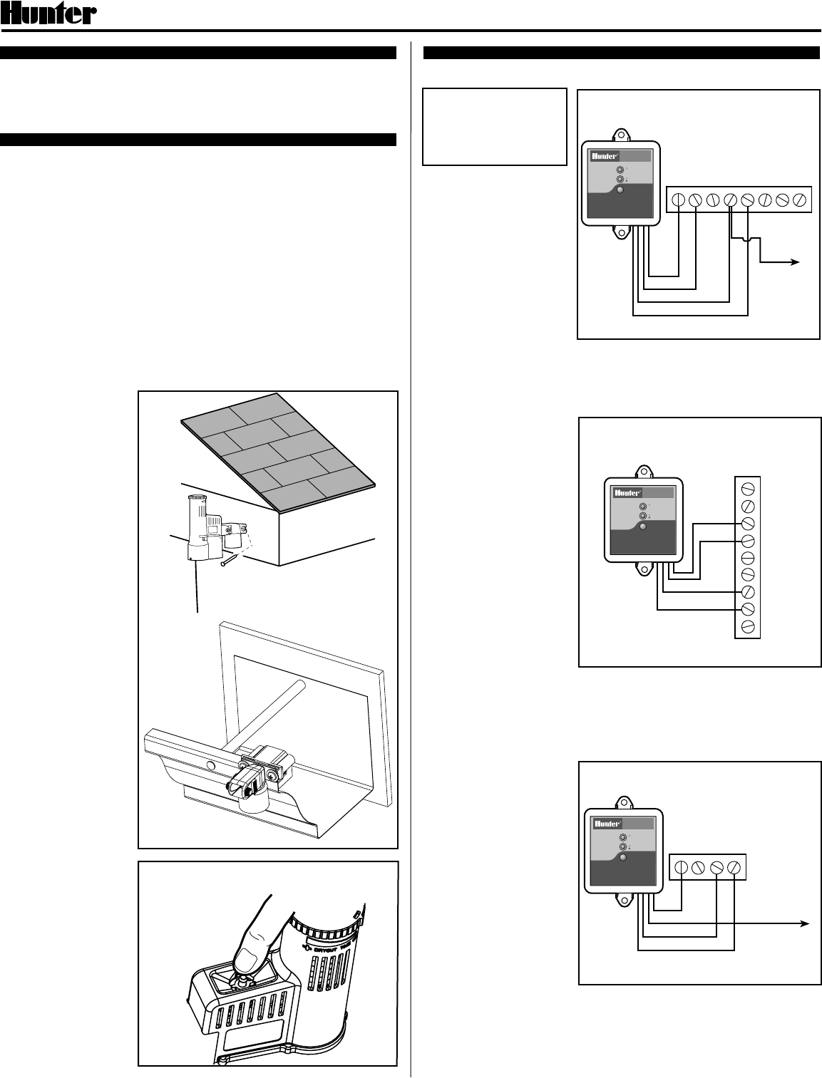
MOUNTING
Standard Mount:
Using the screws provided, mount the Wireless Rain-Clik™ transmitter on any
surface where it will be exposed to unobstructed rainfall, but not in the path of
sprinkler spray. The switch-housing portion must be upright (as pictured), but
the swivel-bracket can be moved for mounting on any angled surface.
Gutter Mount:
Clip the enclosed gutter mounting bracket over the inside lip of the gutter. Attach
the Wireless Rain-Clik™ to the gutter mounting bracket with the screws provided.
Helpful Hints for Mounting:
A. When looking for a suitable location such as on the side of a building or post,
the closer the Wireless Rain-Clik™ is to the controller, the better reception
will be. DO NOT EXCEED 300 feet.
B. The ideal location for mounting is not always the most practical location. In
the case where a compromise must exist (such as low location on a side wall
rather than the preferred high location), note that the Wireless Rain-Clik™
will still work as it will always receive some rainfall – it just will not be as
accurate in its gauging as it could be.
C. As described in the
“Operation” section of
this manual, “reset
rate” refers to the
amount of time it takes
the Wireless Rain-
Clik™ to dry out
sufficiently for the
sprinkler system to be
allowed to come back
on. The mounting
location will affect this
rate and should be
taken into consider-
ation should extreme
conditions exist. For
example, mounting the
Wireless Rain-Clik™
on a very sunny,
southern end of a
building may cause the
Wireless Rain-Clik™
to dry out sooner than
desired. Similarly,
mounting on the
northern end of a
building with constant
shade may keep the
Wireless Rain-Clik™
from drying
soon enough.
Transmitters/Sensor
•Nothing to set up with
this unit after installation
•The unit can be tested
stand-alone as follows:
press and hold the post
on the quick response
section. Within 3
seconds of pressing
and holding this post
down, the LED
protruding from the
potting should blink
once. Release the post,
within 3 seconds the
LED should blink once
again. (Figure 1)
WIRING TO YOUR IRRIGATION SYSTEM
Important:
The Wireless Rain-Clik™ is sold and designed for hook up to
24 Volt irrigation controllers only.
WARNING! This unit is
designed to be installed in
conjunction with 24VAC
circuits only. Do not use
with 110 or 220VAC
circuits.
Receiver Installation,
SRC Controller:
1. Using the hardware
included, mount the
receiver to the wall (use
included wall anchors if
needed). Make sure to put
the rubber cover/gasket
under the unit when
attaching it in an outdoor
location.
2. Attach the two yellow wires
to the AC terminals of the
SRC (polarity does not
matter).
3. Attach the blue wire to the RS terminal.
4. Attach the white wire to the “C” terminal.
5. Attach the valve common wire to the RS terminal.
Receiver Installation,
Pro-C and ICC Controllers:
1. Using the hardware
included, mount the
receiver to the wall (use
included wall anchors if
needed). Make sure to put
the rubber cover/gasket
under the unit when
attaching it in an
outdoor location.
2. Attach the two yellow wires
to the AC terminals of the
controller (polarity does not
matter).
3. Attach the blue wire to one
SEN terminal and the white
wire to the other SEN
terminal of the controller.
A. Receiver Installation, Other Controllers:
1. Using the hardware included, mount the receiver to the wall (use included
wall anchors if needed). Make sure to put the rubber cover/gasket under the
unit when attaching it in an outdoor location.
2. Attach the two yellow wires to the AC terminals of the controllers (polarity
does not matter).
3a. Most controllers use a
normally closed rain
sensor. To attach the
receiver to this type of
controller, attach the blue
wire and the white wire
to the sensor terminals of
the controller, or in-line
with the valve common.
3b. A few controllers on the
market require a normally
open rain sensor. To
attach the receiver to this
type of controller, attach
the blue wire and the
orange wire to the
controller’s sensor input.
®
Wireless Rain-ClikTM Rain Sensors
Installation Instructions
Figure 3
Controller
Figure 4
Gutter
Mount
Standard
Mount
Wireless
Rain Sensor
Hunter SRC
Figure 2
RRSC 1ACAC 2 3
Wireless
Rain Sensor Hunter ICC
SEN
SEN
C
TEST
P MV
AC
AC
G
REM
Red light indicates
sensor is bypassed
GREEN = Sensor is dry
RED = Sensor is wet
SENSOR BYPASS
SENSOR STATUS
WIRELESS
RAIN SENSOR
RAIN SENSOR BYPASS
Press to bypass, press
again to re-enable
P MVC
Wireless
Rain Sensor
AC AC
W
B
Y
YVALVES
B
W
Y
Y
W
B
Y
Y
Common Wire
to all Valves
Figure 1
Manually depress the spindle at
the top of the Wireless Rain-ClikTM
Red light indicates
sensor is bypassed
GREEN = Sensor is dry
RED = Sensor is wet
SENSOR BYPASS
SENSOR STATUS
WIRELESS
RAIN SENSOR
RAIN SENSOR BYPASS
Press to bypass, press
again to re-enable
Red light indicates
sensor is bypassed
GREEN = Sensor is dry
RED = Sensor is wet
SENSOR BYPASS
SENSOR STATUS
WIRELESS
RAIN SENSOR
RAIN SENSOR BYPASS
Press to bypass, press
again to re-enable
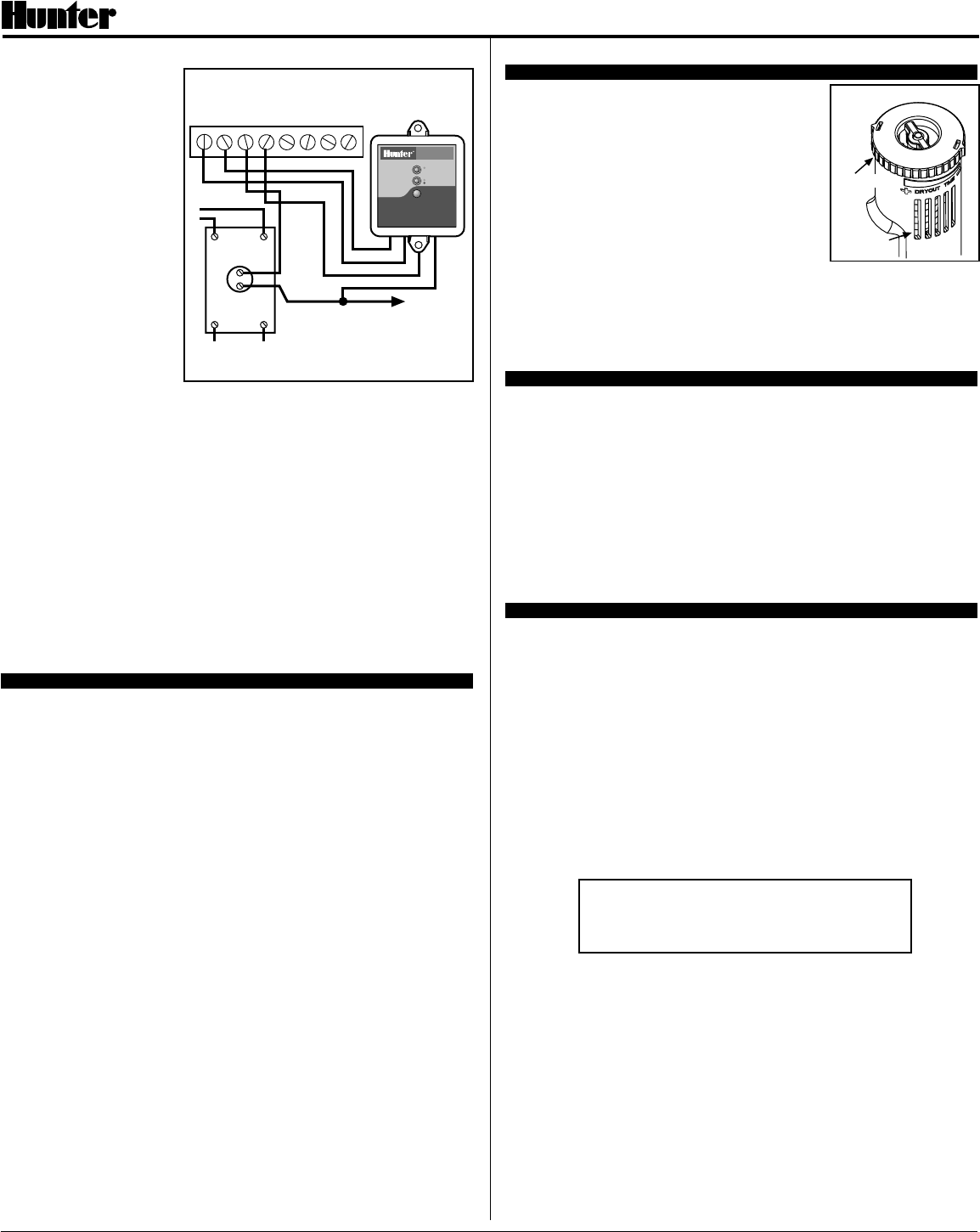
B. 24 Volt Solenoid Valves
with Booster Pump
(See Figure 5)
Locate the common wire
to the solenoid valves and
the common wire leading
to the coil of the relay that
starts the pump. If these
two wires are connected
to the “common” terminal
on the controller,
disconnect both of them.
Twist together these two
wires along with one wire
from the Rain-Clik™, and
secure with a wire nut.
Attach the other wire of
the Wireless Rain-Clik™
receiver to the “common”
terminal on the controller.
Note: The pump circuit
output must be 24 Volts
in this situation. Do not proceed if 110V.
Learning the transmitter address at the receiver:
•Units purchased as a kit will already have their address learned.
•Each transmitter produced has a unique address hard-coded into it. A receiver
must learn this address to work with that transmitter. This step will only be
necessary if transmitters and receivers are purchased separately.
1. Prior to applying power (yellow wires) to the receiver, press and hold the
receivers pushbutton.
2. While the pushbutton is being held apply power to the receiver – the receiver’s
“sensor status” LED should light up yellow indicating the receiver is ready to
learn an address.
3. Push and hold the quick response post on the transmitter/sensor.
4. Within 4 seconds, the receiver’s “sensor status” LED should turn red.
5. Release the transmitter/sensor’s quick response post and within 4 seconds
the LED on the receiver should turn green. The address is now learned and
will be retained even in the event of a power outage.
OPERATION
Once the receiver and transmitter have been installed and the receiver has
learned the transmitter's address, the system is ready to work. The receiver has
two LEDs, which indicate the state of the system. The STATUS LED will be RED
when the sensor is wet (watering disabled), and GREEN when the sensor is dry
(watering enabled). There is also a RED BYPASS LED on the receiver. If this
LED is lit, the rain sensor is bypassed and watering will always be allowed. Even
though the sensor is bypassed, the STATUS LED will continue to alert you of the
state of the sensor (Wet or Dry). If the communication between the transmitter
and the receiver ever breaks down, the transmitter’s status LED will flash red.
ADJUSTMENTS AND OPERATION
The Wireless Rain-Clik™ can keep the irrigation
system from starting or continuing after rainfall.
The time that it takes the Wireless Rain-Clik™ to
reset for normal sprinkler operation after the rain has
stopped is determined by weather conditions (wind,
sunlight, humidity, etc.) These conditions will
determine how fast the hydroscopic discs dry out,
and since the turf is also experiencing the same
conditions, their respective drying rates will roughly
parallel each other. So when the turf needs more
water, the Rain-Clik™ is already reset to allow the
sprinkler system to go at the next scheduled cycle.
There is an adjustment capability on the Wireless
Rain-Clik™ that will slow down the reset rate. By opening the “vent” (see Figure
6) to completely or partially cover the ventilation slots, the hydroscopic discs will
dry more slowly. This adjustment can compensate for an “overly sunny”
installation location, or peculiar soil conditions. Experience will best determine
the ideal vent setting.
BYPASSING THE SENSOR
The sensor may be bypassed by using the built in bypass feature in the SRC,
Pro-C or ICC. On other controllers the sensor may be bypassed by pressing the
“BYPASS” button on the receiver. The RED BYPASS LED on the receiver will
be lit when the sensor is bypassed. Pressing the “BYPASS” button again will
cause the RED BYPASS LED to go back out thus re-enabling the sensor.
Battery Life: The Wireless Rain-Clik™ transmitter is designed to work daily for
up to ten years with the original battery. The sealed unit is available as a
replacement part. Should you need to change the transmitter the receiver will
have to learn the new transmitter address.
There is no required maintenance for the unit. The Wireless Rain-Clik™ does
not have to be removed or covered for “winterizing” purposes.
TROUBLESHOOTING
Follow these simple checks first before assuming the unit is bad and replacing it.
System will not come on at all:
A. First, check to see that the Wireless Rain-Clik™ discs are dry and the switch
“clicks” on and off freely by pressing the top of the spindle.
B. Next, look for breaks in the wire leading to the Wireless Rain-Clik™ receiver
and check all wire junctions.
System will not shut off even after heavy rainfall:
A. Check wiring for correctness (see “Operation Check to Verify Correct Wiring”).
B. Is the rainfall actually hitting the Wireless Rain-Clik™? Check for obstructions
to rainfall such as overhangs, trees or walls.
Manufactured under U.S. Patent Pending
All Rain-ClikTM models are listed by Underwriters Laboratories, Inc. (UL). Samples of these devices have
been evaluated by UL and meet the applicable UL standards for safety.
For information on the complete line
of Hunter products, visit our Web site at
www.HunterIndustries.com
FCC Compliance Notice
This device complies with FCC rules Part 15. Operation is subject to the following
two conditions:
1) This device may not cause harmful interference and
2) This device must accept any interference that may be received, including
interference that may cause undesired operation
Transmitter FCC ID: M3UWRCTX
®
Figure 5
Normally-
Open Relay
12 3 4
Controller
C
Solenoid
Valves
Common
Wire to All
Valves
Pump
or
MV
Line-In
Line-Out (to Pump)
Wireless Rain-ClikTM Rain Sensors
Installation Instructions
Hunter Industries Incorporated • The Irrigation Innovators © 2002 Hunter Industries Incorporated
U.S.A.: 1940 Diamond Street • San Marcos, California 92069 • TEL: (1) 760-744-5240 • FAX: (1) 760-744-7461
www.HunterIndustries.com 23-461 4/02
Wireless
Rain Sensor
AC AC
Y
Y
W
B
Figure 6
Vent Ring
Vents
Red light indicates
sensor is bypassed
GREEN = Sensor is dry
RED = Sensor is wet
SENSOR BYPASS
SENSOR STATUS
WIRELESS
RAIN SENSOR
RAIN SENSOR BYPASS
Press to bypass, press
again to re-enable