Hunter WVC Wireless Valve Controller User Manual LIT 355 RevA WVC OM
Hunter Industries Inc Wireless Valve Controller LIT 355 RevA WVC OM
UserManual.wiki
>
Hunter
>
WVC User Manual
Owners Manual
Navigation menu
Upload a User Manual
Namespaces
Wiki Guide
HTML
PDF
Info
Views
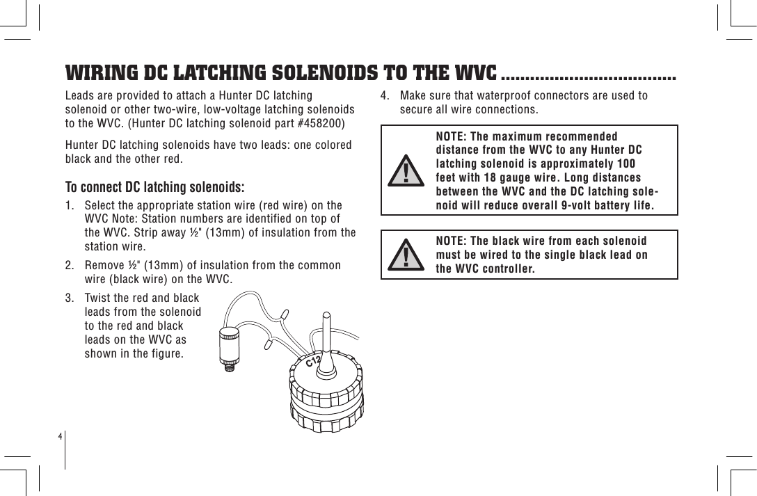
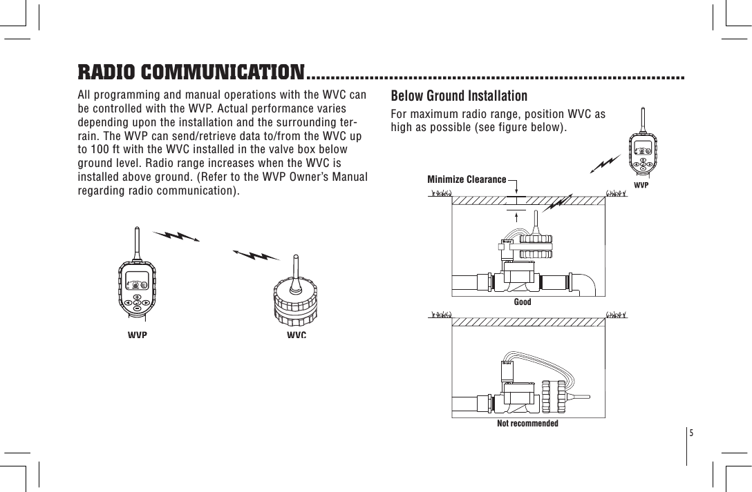
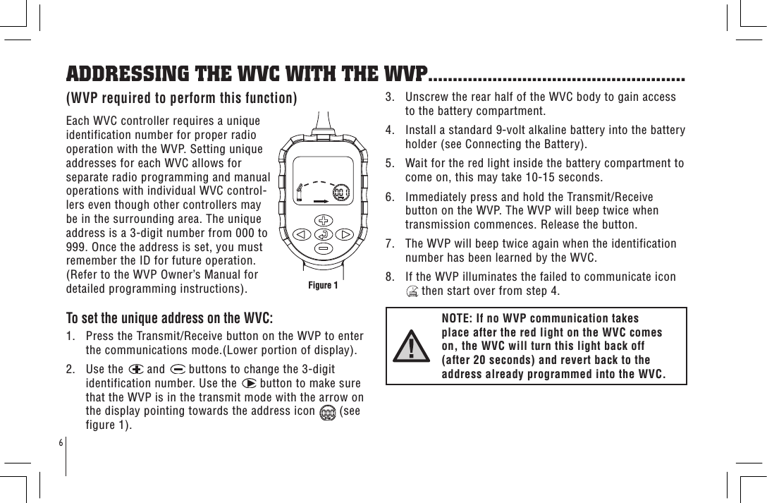
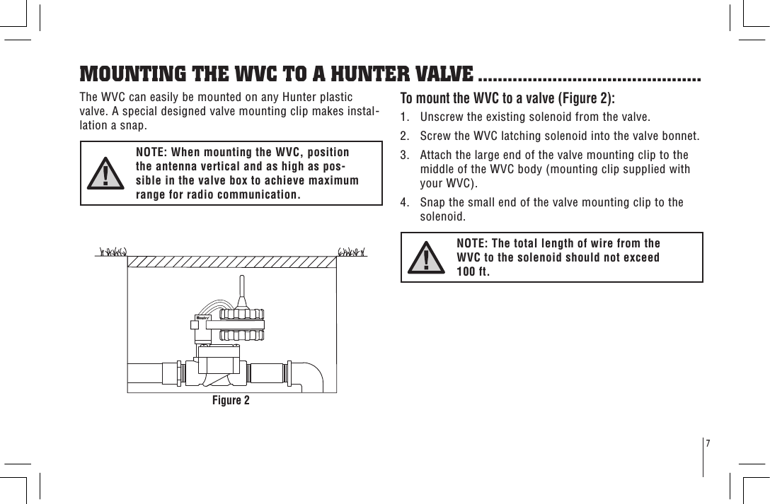
User Manual
Discussion / Help
Navigation