Hunter WVC Wireless Valve Controller User Manual LIT 355 RevA WVC OM
Hunter Industries Inc Wireless Valve Controller LIT 355 RevA WVC OM
Hunter >
Owners Manual

®
WVC
Wireless Valve Controller
Multiple Station Battery Powered
Irrigation Controller
Owner’s Manual and
Installation Instructions


Introduction ...................................................................................................................................................................1
WVC Components...........................................................................................................................................................2
Installing the Battery ......................................................................................................................................................3
Wiring DC Latching Solenoids to the WVC .......................................................................................................................4
Radio Communication.....................................................................................................................................................5
Addressing the WVC with the WVP..................................................................................................................................6
Mounting the WVC to a Hunter Valve...............................................................................................................................7
Alternate Mounting Methods ...........................................................................................................................................8
Connecting a Weather Sensor .........................................................................................................................................9
Programming the Controller............................................................................................................................................9
Specifications...............................................................................................................................................................10
FCC Notice ...................................................................................................................................................................11
Industry of Canada Notice.............................................................................................................................................12
CE Notice .....................................................................................................................................................................12
TABLE OF CONTENTS .....................................................................................


1
The Hunter Wireless Valve Controller (WVC) is a battery-powered, radio programmable controller that can operate up to
two (WVC-200) or four valves (WVC-400). Hunter’s Wireless Battery powered irrigation systems are ideal for commercial/
municipal applications such as street and highway landscaping, medians, parks, construction sites, and other areas that
do not have access to power.
All programming and manual operations with the WVC are accomplished with the Wireless Valve Programmer (WVP). The
WVP is a hand-held programmer that allows you to create programs and conduct manual operations with WVC controllers
in the field. Because the WVP retrieves and transmits data via radio signals, you never have to open a valve box to check
the status or program your controllers.
The following instructions provide information on installing and setting up your WVC. Additional programming instructions
can be found in the WVP Owner’s Manual.
INTRODUCTION ...............................................................................................
2
WVC COMPONENTS........................................................................................
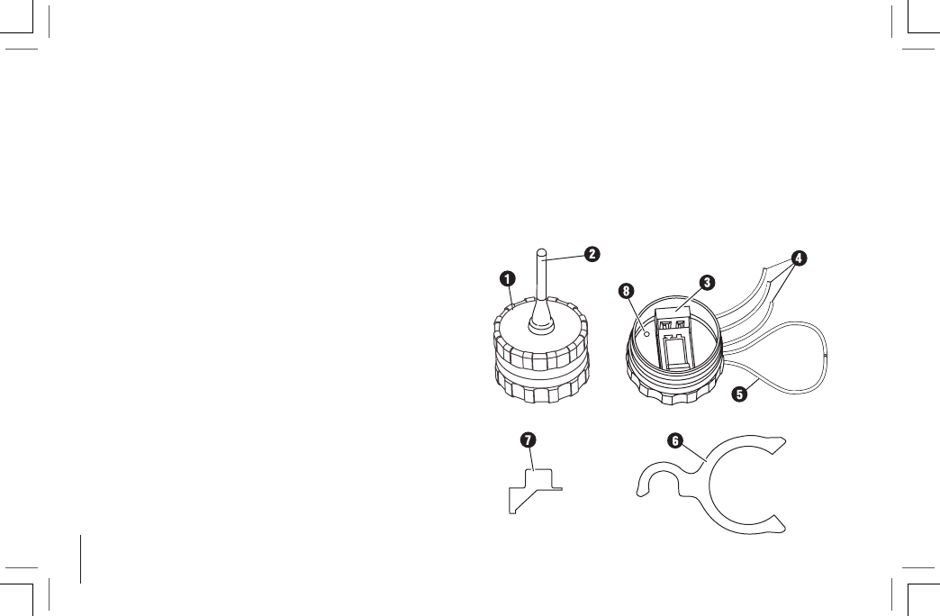
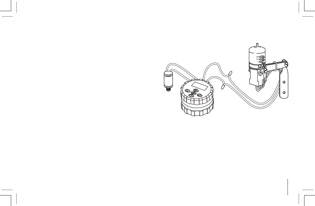
This section provides a brief overview of some of the com-
ponents of the WVC. Each item will be discussed in further
detail later, however, this section can be helpful in getting
acquainted with the different options available.
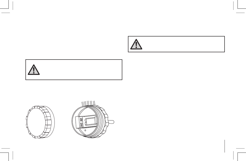
1. WVC Body – The WVC controller is designed to be dirt
tolerant, waterproof, and submersible to 12 feet.
2. External Antennae – Flexible rubber antennae for radio
communication.
3. 9-Volt Battery Holder – The WVC is designed to oper-
ate on a single 9-volt alkaline battery. The battery easily
snaps into the battery holder.
4. Wires for DC Latching Solenoids – Leads are provided
for wiring DC latching solenoids. The red wires are
numbered on top of the WVC to provide station identifi-
cation. The black wire is the common wire.
5. Weather Sensor Wires – A Hunter Mini-Clik® or other
micro-switch type sensor can be connected to the WVC.
6. Valve Mounting Clip – Allows the WVC to be mounted
directly to any Hunter valve. The clip can also be used
in conjunction with the Universal Mounting Adapter.
7. Universal Mounting Adapter – Allows for alternate
methods of mounting the WVC. It can be used to
mount the WVC to the side of the valve box or on a "
(13 mm) diameter section of plastic pipe.
8. LED Indicator Light – Used when setting the WVC
address.
3
The WVC uses a standard 9-volt alkaline battery to operate
the valve and program the controller. Battery life is affected
by the number of valve actuations, along with the distance
the solenoids are from the controller. Under normal service
conditions the battery should provide at least one full year
of service.
NOTE: The WVC has non-volatile memory
that retains all program information when
the battery is removed or in the event the
battery is drained.
To install the battery:
1. Unscrew the rear half of the WVC body to gain access
to the battery compartment.
INSTALLING THE BATTERY...........................................................................
2. Snap the battery into the battery holder.
NOTE: The battery holder is designed so
that the battery can only be inserted in one
direction.
3. Make sure no water is inside the battery compartment.
Make sure that the seals are in good condition. Screw
the WVC body halves together to seal the compartment.
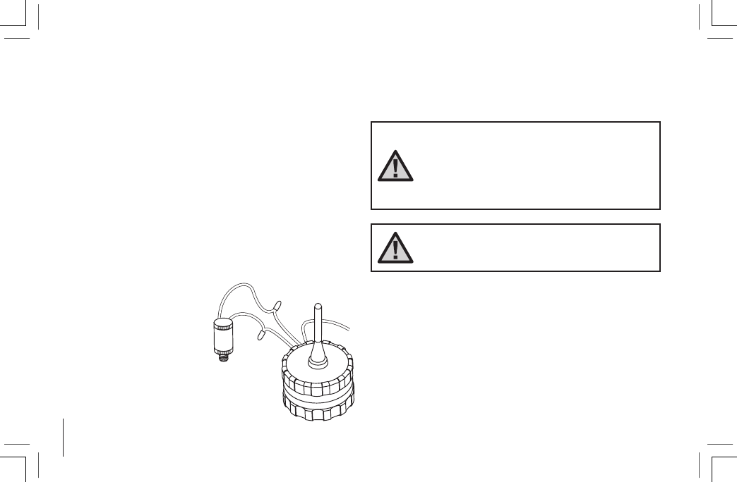
WIRING DC LATCHING SOLENOIDS TO THE WVC ....................................
4
Leads are provided to attach a Hunter DC latching
solenoid or other two-wire, low-voltage latching solenoids
to the WVC. (Hunter DC latching solenoid part #458200)
Hunter DC latching solenoids have two leads: one colored
black and the other red.
To connect DC latching solenoids:
1. Select the appropriate station wire (red wire) on the
WVC Note: Station numbers are identified on top of
the WVC. Strip away " (13mm) of insulation from the
station wire.
2. Remove " (13mm) of insulation from the common
wire (black wire) on the WVC.
3. Twist the red and black
leads from the solenoid
to the red and black
leads on the WVC as
shown in the figure.
4. Make sure that waterproof connectors are used to
secure all wire connections.
NOTE: The maximum recommended
distance from the WVC to any Hunter DC
latching solenoid is approximately 100
feet with 18 gauge wire. Long distances
between the WVC and the DC latching sole-
noid will reduce overall 9-volt battery life.
NOTE: The black wire from each solenoid
must be wired to the single black lead on
the WVC controller.
C
1
2
5
Good
Not recommended
Minimize Clearance
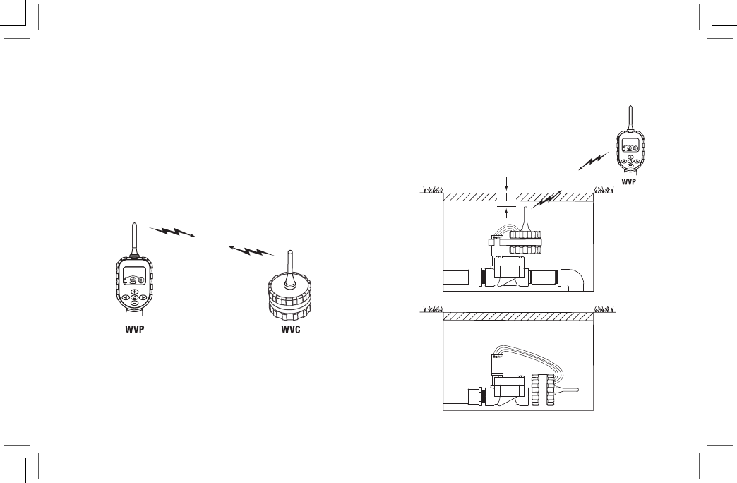
RADIO COMMUNICATION..............................................................................
All programming and manual operations with the WVC can
be controlled with the WVP. Actual performance varies
depending upon the installation and the surrounding ter-
rain. The WVP can send/retrieve data to/from the WVC up
to 100 ft with the WVC installed in the valve box below
ground level. Radio range increases when the WVC is
installed above ground. (Refer to the WVP Owner’s Manual
regarding radio communication).
Below Ground Installation
For maximum radio range, position WVC as
high as possible (see figure below).
6
ADDRESSING THE WVC WITH THE WVP....................................................
(WVP required to perform this function)
Each WVC controller requires a unique
identification number for proper radio
operation with the WVP. Setting unique
addresses for each WVC allows for
separate radio programming and manual
operations with individual WVC control-
lers even though other controllers may
be in the surrounding area. The unique
address is a 3-digit number from 000 to
999. Once the address is set, you must
remember the ID for future operation.
(Refer to the WVP Owner’s Manual for
detailed programming instructions).
To set the unique address on the WVC:
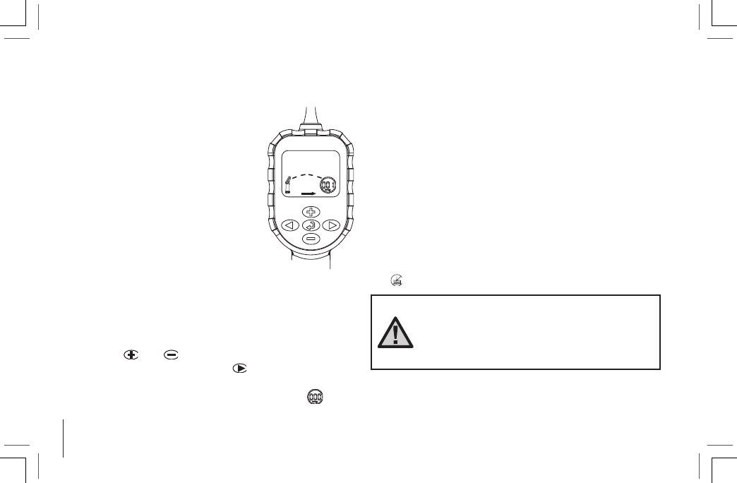
1. Press the Transmit/Receive button on the WVP to enter
the communications mode.(Lower portion of display).
2. Use the and buttons to change the 3-digit
identification number. Use the button to make sure
that the WVP is in the transmit mode with the arrow on
the display pointing towards the address icon (see
figure 1).
3. Unscrew the rear half of the WVC body to gain access
to the battery compartment.
4. Install a standard 9-volt alkaline battery into the battery
holder (see Connecting the Battery).
5. Wait for the red light inside the battery compartment to
come on, this may take 10-15 seconds.
6. Immediately press and hold the Transmit/Receive
button on the WVP. The WVP will beep twice when
transmission commences. Release the button.
7. The WVP will beep twice again when the identification
number has been learned by the WVC.
8. If the WVP illuminates the failed to communicate icon
then start over from step 4.
NOTE: If no WVP communication takes
place after the red light on the WVC comes
on, the WVC will turn this light back off
(after 20 seconds) and revert back to the
address already programmed into the WVC.
Figure 1
7
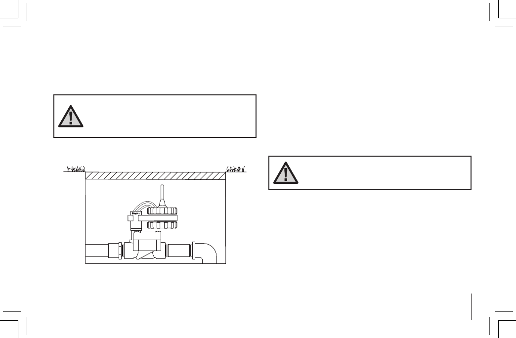
MOUNTING THE WVC TO A HUNTER VALVE .............................................
The WVC can easily be mounted on any Hunter plastic
valve. A special designed valve mounting clip makes instal-
lation a snap.
NOTE: When mounting the WVC, position
the antenna vertical and as high as pos-
sible in the valve box to achieve maximum
range for radio communication.
To mount the WVC to a valve (Figure 2):
1. Unscrew the existing solenoid from the valve.
2. Screw the WVC latching solenoid into the valve bonnet.
3. Attach the large end of the valve mounting clip to the
middle of the WVC body (mounting clip supplied with
your WVC).
4. Snap the small end of the valve mounting clip to the
solenoid.
NOTE: The total length of wire from the
WVC to the solenoid should not exceed
100 ft.
Figure 2
8
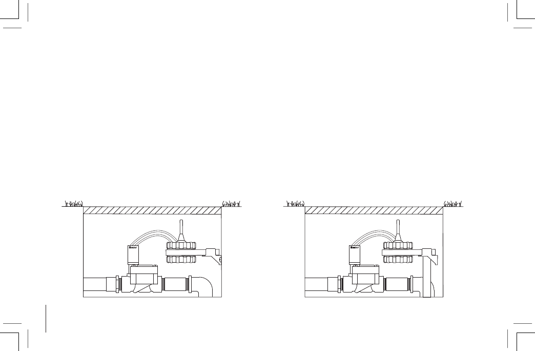
ALTERNATE MOUNTING METHODS ............................................................
A universal mounting clip and mounting adapter are also
provided with the WVC. These accessories provide for
alternate methods of mounting the controller either to the
side of the valve box or stake mounted within the valve box.
Valve Box Mounting Method (Figure 3)
1. Position the universal mounting adapter on the side of
the valve box. Make sure that the bracket is positioned
so that the controller is as high up in the valve box
as possible, but does not interfere with the top of the
valve box cover.
2. Drive two screws to secure the adapter to the side of
the valve box.
3. Attach the WVC to the mounting clip and slide it on the
end of the mounting adapter.
Stake Mounting Method (Figure 4)
The universal mounting adapter can also be used to stake
mount the WVC.
1. Cut a section of " (13mm) diameter plastic pipe.
2. Drive the pipe into the ground inside the valve box to
position the WVC to the desired height.
3. Slip the universal mounting adapter on top of the pipe.
4. Attach the WVC to the mounting clip and slide onto the
adapter.
Figure 4
Figure 3
9
A Hunter Mini-Clik® rain sensor or other micro-switch type
weather sensor can be connected to the WVC. The purpose
of this sensor is to stop watering when weather conditions
dictate.
To connect a weather sensor to the WVC:
1. Cut the yellow wire loop attached to the WVC at
approximately the middle of the loop.
2. Remove approximately " (13mm) of insulation from
each wire. Attach each wire to each of the wires of the
weather sensor.
3. Secure both wire connections with waterproof
connectors.
CONNECTING A WEATHER SENSOR ...........................................................
The WVC is easy to program with its companion, the WVP
Wireless Valve Programmer. The easy-to-understand push
button design of the WVP allows you to step through the
process of programming and activating manual watering
with the press of a button. Further information on operating
the WVP can be found in your WVP Owner’s Manual.
PROGRAMMING THE CONTROLLER ...........................................................

10
Operating Specications
• Station run time: 0 to 4 hours in 1-minute increments
• Start times: 9 per day
• Day of the week calendar
• Interval watering
• AM/PM or 24-hour clock option
• Start time stacking for each station
• One button manual start and advance
• Programmable rain delay for 1 to 7 days
Electrical Specications
• Solenoids: Operates 6 to 9-volt DC latching solenoids
• Battery: Standard 9-volt alkaline battery (not included),
one year minimum life. Battery not required for pro-
gram backup.
• Memory: Non-volatile for program data•
Weather sensor compatible
• Frequency of operation:
900 MHz ISM band (U.S./Aust.), 868 MHz (Europe)
Dimensions
WVC – 3.25" D x 5" H
WVP – 3" W x 11.5" L x 2" H
SPECIFICATIONS .............................................................................................

11
FCC NOTICE.......................................................................................................
This notice applies only to models WVC-200 and WVC-400
FCC ID: M3UWVC
This equipment has been tested and found to comply with the limits for class B digital device, pursuant to part 15 of the
FCC Rules. These limits are designed to provide reasonable protection against harmful interference in a residential instal-
lation. This equipment generates, uses and can radiate radio frequency energy and if not installed and used in accordance
with the instructions, may cause harmful interference to radio communications. However, there is no guarantee that
interference will not occur in a particular installation. If this equipment does cause harmful interference to radio or televi-
sion reception, which can be determined by turning the equipment off and on, the user is encouraged to try to correct the
interference by one or more of the following measures:
• Reorient or relocate the receiving antenna
• Increase the separation between the equipment and the antenna
• Consult the dealer or an experienced radio/TV technician for help
The user is cautioned that changes and modifications made to the equipment without the approval of the manufacturer
could void the user’s authority to operate this equipment.
Hunter Industries Incorporated • The Irrigation Innovators © 2003 Hunter Industries Incorporated
1940 Diamond Street • San Marcos, California 92069
www.HunterIndustries.com
P/N 700912 LIT-355 3/03
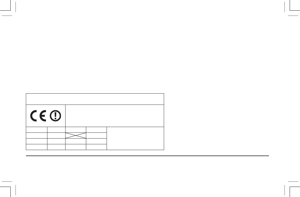
CE Notice: this notice applies only to models
WVC-200-E and WVC-400-E.
Important Notice:
Low power RF product operating in
869.700-870.000MHz band for indoor or
outdoor home and commercial use.
AUS B DK FIN Member states in the EU
with restrictive use for this
product are crossed out.
F D GR IRE
I LUX NL P
E S UK
INDUSTRY OF CANADA NOTICE ...................................................................
This notice applies only to models WVC-200 and WVC-400
IC: 2772-WVC
The term “IC:” before the certification/registration number only signifies that the Industry of Canada technical specifica-
tions were met.
Operation is subject to the following two conditions: (1) this device may not cause interference, and (2) this device must
accept any interference, including interference that may cause undesired operation of the device.
CE NOTICE.........................................................................................................