Hyde Park Electronics Schneider Electric Sensor Competency Center XGCS8 RFID Reader User Manual Ositrack compact station
Hyde Park Electronics LLC DBA Schneider Electric Sensor Competency Center RFID Reader Ositrack compact station
User Manual
W916556690111
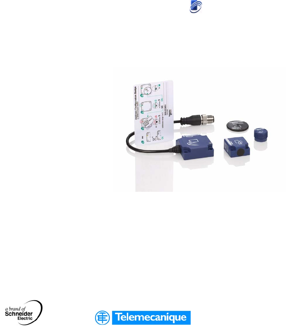
RFID Ositrack
Compact stations
Stations compactes
User Guide / Manuel utilisateur
W916556690111
27/06/2007
www.telemecanique.com

2
English

3
English
Table of Contents
Safety Information . . . . . . . . . . . . . . . . . . . . . . . . . . . . . . . . . . . . 5
About the Book . . . . . . . . . . . . . . . . . . . . . . . . . . . . . . . . . . . . . . .7
Chapter 1 General . . . . . . . . . . . . . . . . . . . . . . . . . . . . . . . . . . . . . . . . . . . . .9
Presentation . . . . . . . . . . . . . . . . . . . . . . . . . . . . . . . . . . . . . . . . . . . . . . . . . . . . . 9
System Presentation . . . . . . . . . . . . . . . . . . . . . . . . . . . . . . . . . . . . . . . . . . . . . . 10
Exchange Principle . . . . . . . . . . . . . . . . . . . . . . . . . . . . . . . . . . . . . . . . . . . . . . . 11
Equipment in the Ositrack Range . . . . . . . . . . . . . . . . . . . . . . . . . . . . . . . . . . . . 12
Chapter 2 Installing the system . . . . . . . . . . . . . . . . . . . . . . . . . . . . . . . . . 13
Presentation . . . . . . . . . . . . . . . . . . . . . . . . . . . . . . . . . . . . . . . . . . . . . . . . . . . . 13
Defining the System Environment. . . . . . . . . . . . . . . . . . . . . . . . . . . . . . . . . . . . 14
Setting up the Station . . . . . . . . . . . . . . . . . . . . . . . . . . . . . . . . . . . . . . . . . . . . . 18
Connecting the Station . . . . . . . . . . . . . . . . . . . . . . . . . . . . . . . . . . . . . . . . . . . . 25
Wiring a Modbus/Uni-Telway Network . . . . . . . . . . . . . . . . . . . . . . . . . . . . . . . . 27
Wiring an Ethernet Modbus TCP/IP network. . . . . . . . . . . . . . . . . . . . . . . . . . . . 30
Connecting the TCS AMT31FP splitter box . . . . . . . . . . . . . . . . . . . . . . . . . . . . 31
Chapter 3 Setting the System Parameters. . . . . . . . . . . . . . . . . . . . . . . . .35
Presentation . . . . . . . . . . . . . . . . . . . . . . . . . . . . . . . . . . . . . . . . . . . . . . . . . . . . 35
Setting the Station Parameters . . . . . . . . . . . . . . . . . . . . . . . . . . . . . . . . . . . . . . 36
Setting the PLC Parameters . . . . . . . . . . . . . . . . . . . . . . . . . . . . . . . . . . . . . . . . 40
Chapter 4 Operating Principles. . . . . . . . . . . . . . . . . . . . . . . . . . . . . . . . . .41
Presentation . . . . . . . . . . . . . . . . . . . . . . . . . . . . . . . . . . . . . . . . . . . . . . . . . . . . 41
Memory Zones . . . . . . . . . . . . . . . . . . . . . . . . . . . . . . . . . . . . . . . . . . . . . . . . . . 42
Station Memory Zone . . . . . . . . . . . . . . . . . . . . . . . . . . . . . . . . . . . . . . . . . . . . . 43
Tag Memory Zone. . . . . . . . . . . . . . . . . . . . . . . . . . . . . . . . . . . . . . . . . . . . . . . . 46
Chapter 5 Communicating with the Uni-Telway Protocol . . . . . . . . . . . . 51
Presentation . . . . . . . . . . . . . . . . . . . . . . . . . . . . . . . . . . . . . . . . . . . . . . . . . . . . 51
General . . . . . . . . . . . . . . . . . . . . . . . . . . . . . . . . . . . . . . . . . . . . . . . . . . . . . . . . 52
Requests . . . . . . . . . . . . . . . . . . . . . . . . . . . . . . . . . . . . . . . . . . . . . . . . . . . . . . . 54
Programming. . . . . . . . . . . . . . . . . . . . . . . . . . . . . . . . . . . . . . . . . . . . . . . . . . . . 66

4
English
Chapter 6 Communicating with the Modbus Protocol. . . . . . . . . . . . . . . 51
Presentation. . . . . . . . . . . . . . . . . . . . . . . . . . . . . . . . . . . . . . . . . . . . . . . . . . . . . 51
General . . . . . . . . . . . . . . . . . . . . . . . . . . . . . . . . . . . . . . . . . . . . . . . . . . . . . . . . 70
Requests . . . . . . . . . . . . . . . . . . . . . . . . . . . . . . . . . . . . . . . . . . . . . . . . . . . . . . . 73
Programming . . . . . . . . . . . . . . . . . . . . . . . . . . . . . . . . . . . . . . . . . . . . . . . . . . . . 79
Chapter 7 Integration Tips . . . . . . . . . . . . . . . . . . . . . . . . . . . . . . . . . . . . . 81
Tips . . . . . . . . . . . . . . . . . . . . . . . . . . . . . . . . . . . . . . . . . . . . . . . . . . . . . . . . . . . 81
Chapter 8 Diagnostics. . . . . . . . . . . . . . . . . . . . . . . . . . . . . . . . . . . . . . . . . 85
Diagnosing a Fault. . . . . . . . . . . . . . . . . . . . . . . . . . . . . . . . . . . . . . . . . . . . . . . . 85
W916556690111 27/06/2007 5
§
English
Safety Information
Important Information
NOTICE Read these instructions carefully, and look at the equipment to become familiar with
the device before trying to install, operate, or maintain it. The following special
messages may appear throughout this documentation or on the equipment to warn
of potential hazards or to call attention to information that clarifies or simplifies a
procedure.
The addition of this symbol to a Danger or Warning safety label indicates
that an electrical hazard exists, which will result in personal injury if the
instructions are not followed.
This is the safety alert symbol. It is used to alert you to potential personal
injury hazards. Obey all safety messages that follow this symbol to avoid
possible injury or death.
DANGER indicates an imminently hazardous situation, which, if not avoided,
will result in death or serious injury.
DANGER
WARNING indicates a potentially hazardous situation, which, if not avoided, can
result in death, serious injury, or equipment damage.
WARNING
CAUTION indicates a potentially hazardous situation, which, if not avoided, can
result in injury or equipment damage.
CAUTION

Safety Information
6W916556690111 27/06/2007
English
PLEASE NOTE Electrical equipment should be installed, operated, serviced, and maintained only by
qualified personnel. No responsibility is assumed by Schneider Electric for any
consequences arising out of the use of this material.
© 2007 Schneider Electric. All Rights Reserved.

W916556690111 27/06/2007 7
English
About the Book
At a Glance
Document Scope This manual describes how to use Ositrack compact stations and associated
accessories..
Related
Documents
User Comments We welcome your comments about this document. You can reach us by e-mail at
techpub@schneider-electric.com
Title of Documentation Reference Number
User Guide: Splitter box, Ethernet Modbus TCP/IP 1655668 01
User Guide: Hand-held terminal 1706482 01

About the Book
8W916556690111 27/06/2007
English

W916556690111 27/06/2007 9
English
1
General
Presentation
Aim of this
Chapter
This chapter presents the Ositrack compact stations and the associated range of
equipment.
What's in this
Chapter?
This chapter contains the following topics:
Topic Page
System Presentation 10
Exchange Principle 11
Equipment in the Ositrack Range 12

General
10 W916556690111 27/06/2007
English
System Presentation
Definition of
RFID
RFID is the use of radio transmission to identify and locate objects.
An RFID system is based on three main components:
A reader (Read/Write station)
A radio antenna
An electronic tag
Operation of an
RFID System
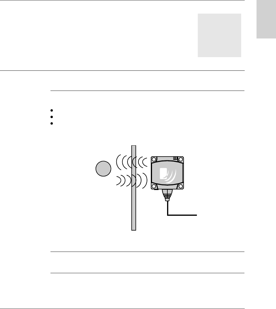
The tag is fixed on, or in, the object to be tracked or identified. There is no contact
with the reader. This means that the tag can be placed inside objects (boxes, bags,
etc) and that the reader can be positioned behind a protective screen, as long as the
materials are not metallic.
When a tag enters the field generated by the reader, it detects the signal and
exchanges the data (read or write) between its memory and the reader.
Presentation of
the Ositrack
Offer
Ositrack is an RFID system offering:
Traceability and tracking of items
Flexibility of production systems
Various types of access control
An open system:
System compatible with tags that comply with standards ISO 14 443 and ISO 15
693
Modbus, Modbus TCP/IP and Uni-Telway protocols.
A simple system:
No station programming
Data formatted in accordance with PLC standards (16-bit words)
Automatic configuration of communication parameters (speed, format, etc)
Quick wiring using M12 connectors
Extensive range of cables and fixing accessories
Possibility of using metal supports
Integrated system:
Reader, radio antenna and network functions in the same unit
The smallest industrial RFID reader
General
W916556690111 27/06/2007 11
English
Exchange Principle
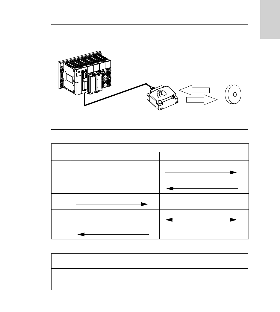
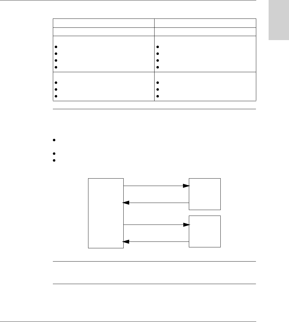
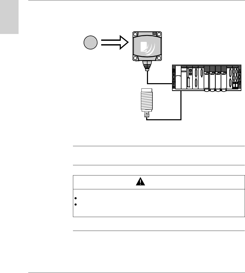
Presentation The compact station is used to send information from the tag to the PLC and vice
versa, as described below:
Phases in the
Process
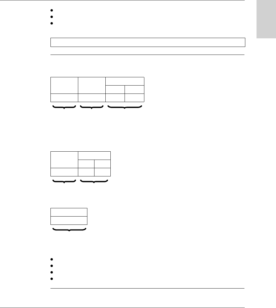
The following table shows the various exchange phases:
Notes:
PLC Station Tag
Phase Exchanges
PLC Station Station Tag
1 Look for a tag in the dialog zone
2 Positive response
3 Send a read/write command
4 Execution of the command (with checks)
5 Send back report
1 If phase 3 is carried out with no tag present, an error message is sent back to the
PLC.
2 If an error is detected in phase 4, this phase is automatically restarted (up to 3
times). If an error is still detected at the end of phase 4, an error report is sent back
in phase 5.

General
12 W916556690111 27/06/2007
English
Equipment in the Ositrack Range
Cabling via M12 connector:
- Splitter boxes suitable for
Schneider networks (Modbus, Uni-
Telway, Ethernet)
- Network powered between the
station and the splitter box
- Range of cables
Compact stations incorporating all
the RFID and network functions in the
same unit
Industrial tags
Ositrack station
Maintenance and
configuration tool
SHIFT2ND
ALT
CAPS
CTRL
CHG
LOW
BAT
Osit rack
ON OFF
0
SHIFT CTRL ALT ESC
@
B
F3
-
J
Insert
+
K
~
#
A
F2
"E
Home
*
I
Delete
=
L
CAPS
LOCK
'F
End
&
C
<$
D
>
O
P%Q
R
G
Menu
(
M
[
/
N
]
\
H
Help
)
S
.
TU
,
VW
:
XY
;
Z
!
7 8 9
BACK
SPACE
?
PG
PG
4 5 6
1 2 3
TAB
TAB
i
SPAC E
DN
UP
2ND
Ositrack
24V
IN OUT
Mounting

W916556690111 27/06/2007 13
English
2
Installing the system
Presentation
Aim of this
Chapter
This chapter describes the procedure for installing compact stations.
What's in this
Chapter?
This chapter contains the following topics:
Topic Page
Defining the System Environment 14
Setting up the Station 18
Connecting the Station 25
Wiring a Modbus/Uni-Telway Network 27
Wiring an Ethernet Modbus TCP/IP network 30
Connecting the TCS AMT31FP splitter box 31

Installing the System
14 W916556690111 27/06/2007
English
Defining the System Environment
Station
Characteristics
The following table gives the technical characteristics of the compact stations:
Type of station XGC S4901201 - C format XGC S8901201 - D format
Temperature Operation -25...+55°C (-13...+131°F)
Storage -40...+85°C (-40...+185°F)
Degree of protection IP67 according to IEC60529
Vibration resistance
EN 60068.2.27
EN 60068.2.6
2 mm (0.078 in) from 5 to 29.5 Hz/7 g (7 gn) from 29.5 to 150 Hz
30 g (30 gn) / 11 ms
Resistance to mechanical shocks IK02 according to EN 50102
Standards/Certifications UL 508, CE, EN 300330, EN 301489-01/03, FCC Part 15
Immunity to disturbance Immunity to electrostatic discharges, radiated electromagnetic fields, fast
transients, electrical surges, conducted and induced interference and power
frequency magnetic field according to IEC61000.
Unit dimensions 40x40x15 mm (1.57x1.57x0.59 in) 80x80x26 mm (3.15x3.15x1.02 in)
RFID frequency 13.56 MHz
Type of associated tag Standardized ISO 15693 and ISO 14443 tags.
Nominal range
(depending on associated tag)
18...70 mm (0.70...2.75 in) 20...100 mm (0.78...3.94 in)
Nominal power supply 24 V PELV
Power supply voltage limits 19.2...29 V including ripple
Power consumption < 60 mA
Serial link Type RS485
Protocol Modbus RTU / Uni-Telway (Uni-Telway from version V3.8)
Speed 9600...115,200 Bauds: Automatic detection
Display 1 bi-color LED for network communication and 1 bi-color LED for RFID
communication (Tag present, Station/tag dialog)
Connection One shielded 5-way male M12 connector for connection to the communication
network and power supply
Tightening torque for the fixing
screws
< 1 Nm (8.85 lbf-in) < 3 Nm (26.55 lbf-in)

Installing the System
W916556690111 27/06/2007 15
English
These RFID compact stations complies with part 15 of the FCC Rules.
Operation is subject to the following two conditions:
(1) These devices may not cause harmful interference, and
(2) these devices must accept any interference received, including interference that
may cause undesired operation.
References :
Changes or modifications not expressly approved by the party responsible for
compliance could void the user’s authority to operate the equipment.
XGC S4901201 XGC S8901201
FCC ID TW6XGCS4 TW6XGCS8
IC info 7002B-XGCS4 7002B-XGCS8
Note:
The manufacturer is not responsible for any radio or TV interference caused by
unauthorized modifications to this equipment. Such modifications could void the
user’s authority to operate the equipment.

Installing the System
16 W916556690111 27/06/2007
English
Tag
Characteristics
The following table gives the technical characteristics of the tags:
Type of tag XGH
B445345
XGH
B444345
XGH
B320345
XGH
B221346
XGH
B211345
XGH B90E340
Temperature Operation -25...+70 °C
(-13...+158°F)
-25...+55 °C
(-13...+131°F)
Storage -40...+85 °C
(-40...+185°F)
-40...+55 °C
(-40...+131°F)
Degree of protection IP68 IP65 IP68 IP65
Standards supported ISO 14443 ISO 15693
Vibration resistance
EN 60068.2.27
EN 60068.2.6
2 mm (0.078 in) from 5 to 29.5 Hz / 7 g (7 gn) from 29.5 to 150 Hz
30 g (30 gn) / 11 ms
Resistance to mechanical shocks IK02 according to EN 50102
Dimensions 40x40x15 mm
(1.57x1.57x0.59 in)
∅ 30x3 mm
(1.18x0.12 in)
26x26x13 mm
(1.02x1.02x
0.51 in)
∅ 18 mm
(0.70 in)
58x85.5x1 mm
(2.28x3.34x
0.039 in)
Casing materials PBT+PC PC PBT+PC PVC
Mounting method Screw or clip Screw Screw or clip Threaded
hole
-
Tightening torque for the fixing
screws
< 1 Nm (8.85 lbf-in) --
Memory capacity (bytes) 13,632 3,408 112 256 256 256
Type of memory EEPROM
Type of operation Read/Write
Type of associated station XGC S•
Nominal
range
Read/
Write
XGC S4 30 mm
(1.18 in)
33 mm
(1.30 in)
48 mm
(1.89 in)
40 mm
(1.57 in)
18 mm
(0.70 in)
70 mm
(2.75 in)
XGC S8 40 mm
(1.57 in)
48 mm
(1.89 in)
65 mm
(2.56 in)
55 mm
(2.16 in)
20 mm
(0.78 in)
100 mm
(3.94 in)
Number of read cycles Unlimited
Number of write cycles 100,000 guaranteed across the whole temperature range
Number of write cycles at 30°C Typically 2.5 million
Read time SeeRead/Write Time, p. 47
Write time SeeRead/Write Time, p. 47
Retention period 10 years

Installing the System
W916556690111 27/06/2007 17
English
Splitter Box
Characteristics
The splitter box TCS AMT31FP is used to connect 1 to 3 XGCS compact stations to
an RS485 network, ensuring distribution of the power supply.
Data is exchanged with the Ositrack stations using the Modbus protocol.
The following table gives the technical characteristics of the TCS AMT31FP splitter
box:
The XGS Z33ETH splitter box performs the same functions using the Modbus TCP/
IP protocol. For further information, see manual reference 165566801.
Characteristics
Storage temperature -40...+85°C (-40...+185°F)
Operating temperature -25...+55°C (-13...+131°F)
Degree of protection IP65
Power supply 24 V PELV (19.2...29 V including ripple)
Stations 5-way female M12 connector
Conformity to standards CE
LED indicators Power supply (green)
Installing the System
18 W916556690111 27/06/2007
English
Setting up the Station
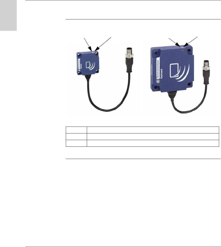
Presentation of
the Stations
For further information on the operation of the LEDs, see Diagnostics, p. 85.
Item no. Description
1 TAG: LED relating to the tags
2 COM: LED relating to communication
C format compact station D format compact station
2121
Installing the System
W916556690111 27/06/2007 19
English
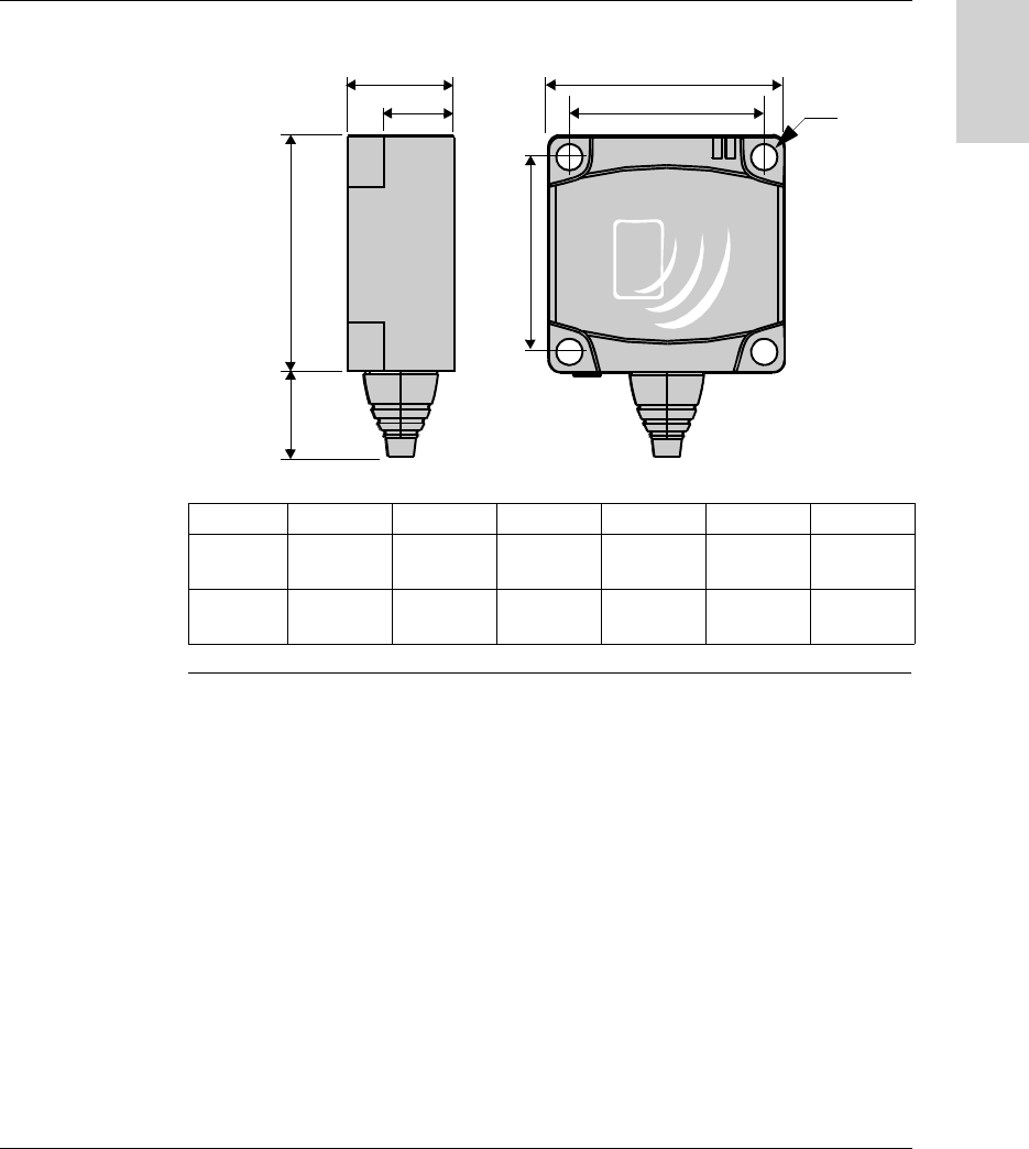
Station
Dimensions
Dimensions in mm (inches):
abcdef
XGC S4
C format
14 (0.55) 40 (1.57) 15 (0.59) 9.8 (0.38) 33 (1.3) 4.5 (0.17)
XGC S8
D format
14 (0.55) 80 (3.15) 26 (1.02) 16 (0.63) 65 (2.56) 5.5 (0.21)
b
c
d
b
e
e
a
f
Installing the System
20 W916556690111 27/06/2007
English
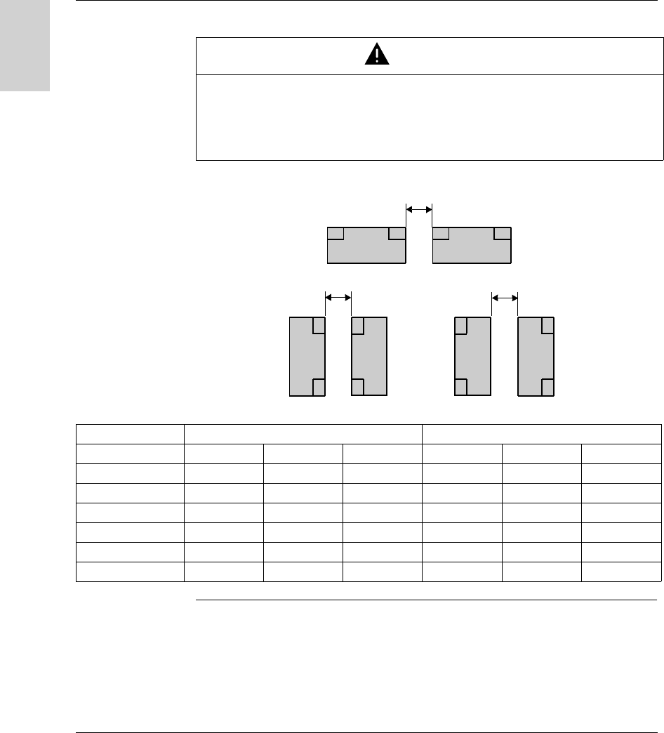
Distances
Between
Stations
Distances between two identical stations according to the tags used:
Distances in mm (inches):
CAUTION
UNINTENDED OPERATION
Follow the installation instructions below relating to distances between 2 stations.
When two stations are too close to one another, there is a risk of mutual
disturbance.
Failure to follow this instruction can result in injury or equipment damage.
d2
d1
d3
Tag XGC S4 - C format XGC S8 - D format
d1 d2 d3 d1 d2 d3
XGH B90E340 310 (12.20) 550 (21.65) 120 (4.72) 430 (16.92) 750 (29.52) 280 (11.02)
XGH B221346 200 (7.87) 320 (12.59) 100 (3.93) 280 (11.02) 530 (20.86) 260 (10.23)
XGH B320345 140 (5.51) 360 (14.17) 110 (4.33) 310 (12.20) 540 (21.25) 240 (9.44)
XGH B211345 210 (8.26) 180 (7.08) 60 (2.36) 200 (7.87) 370 (14.56) 170 (6.69)
XGH B444345 90 (3.54) 190 (7.48) 30 (1.18) 310 (12.20) 400 (15.74) 160 (6.29)
XGH B445345 110 (4.33) 170 (6.69) 30 (1.18) 310 (12.20) 380 (14.96) 160 (6.29)
Installing the System
W916556690111 27/06/2007 21
English
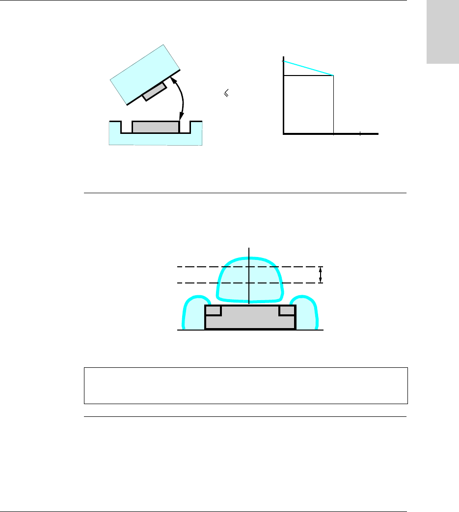
Angular
Positioning
The angle between the station and the tag modifies the dialog distance according to
the graph below:
K = correction factor to be applied to the nominal range.
Reading distance = nominal range x K.
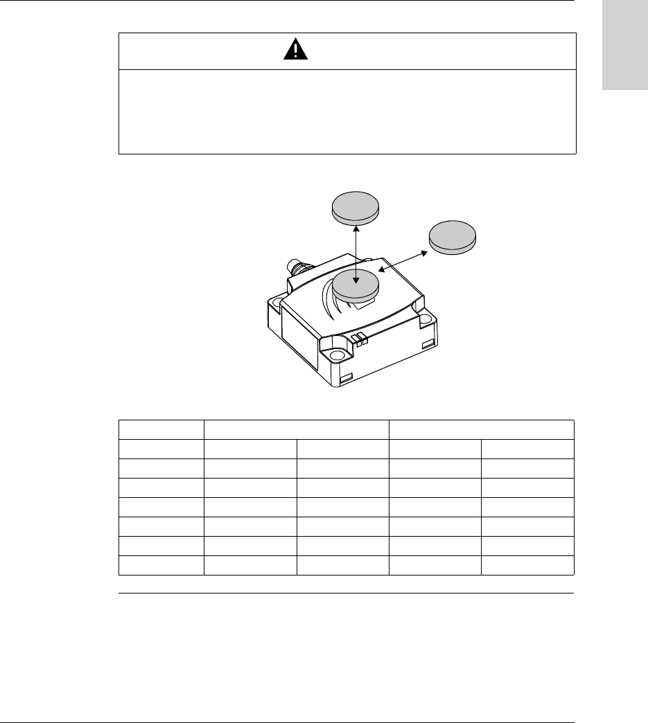
Sensing Zones The dialog zones of the compact stations are circular. There is no recommended
direction for the movement of the tag. The following diagram shows the dialog zones
of the compact stations:
(1) Recommended movement zone: between 0.4 and 0.8 Pn.
060
90
0,85
1
K
α (°)
α
α
60
°
Note: Nominal range (Pn)
Conventional range, which does not take dispersions (manufacturing, temperature,
voltage, mounting in metal) into account.
Pn
(1)
Installing the System
22 W916556690111 27/06/2007
English
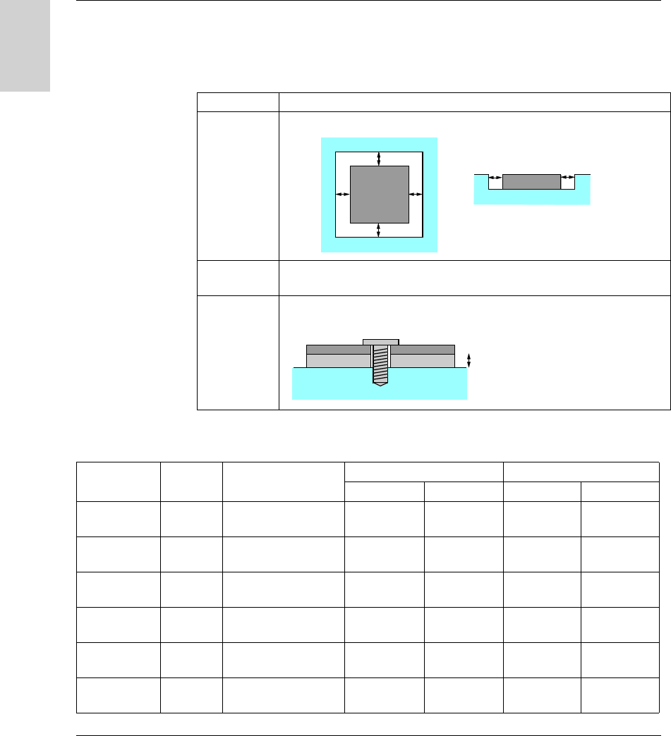
Mounting in
metal
The presence of metal close to tags and stations affects the nominal range (Read/
Write distance).
The following table gives the minimum permissible mounting positions in a metal
block:
The following table shows the effect on the nominal range when the station and the
tag are mounted in metal in accordance with the most unfavorable cases given
above:
References Description
XGC S4
XGC S8
XGH B221346
XGH B444345
XGH B445345
The product is positioned in a steel block:
XGH B90E340
XGH B211345
No metal parts closer than 25 mm (0.98 in) to the tag.
XGH B320345 The tag is fixed with a steel M4 screw (Tightening torque = 1 Nm (8.85 lbf-in) ).
A non-metallic shim must be inserted between the tag and the metal block:
e≥20 mm (0.78 in)
e
ee
e
ee
e≥15 mm (0.59 in)e
Reference Memory
size
Dimensions Reduced range with metal Nominal range
XGC S4 XGC S8 XGC S4 XGC S8
XGH B90E340 256 bytes Badge 85x58x0.8 mm
(3.35x2.28x0.03 in)
58 mm
(2.28 in)
80 mm
(3.15 in)
70 mm
(2.75 in)
100 mm
(3.94 in)
XGH B221346 256 bytes 26x26x13 mm
(1.02x1.02x0.51 in)
30 mm
(1.18 in)
33 mm
(1.29 in)
40 mm
(1.57 in)
55 mm
(2.16 in)
XGH B320345 112 bytes ∅ 30x3 mm
(1.18x0.12 in)
45 mm
(1.77 in)
56 mm
(2.20 in)
48 mm
(1.89 in)
65 mm
(2.56 in)
XGH B211345 256 bytes ∅ 18x12 mm
(0.70x0.47 in)
16 mm
(0.62 in)
15 mm
(0.59 in)
18 mm
(0.70 in)
20 mm
(0.78 in)
XGH B444345 3.3 Kb 40x40x15 mm
(1.57x1.57x0.59 in)
28 mm
(1.10 in)
34 mm
(1.33 in)
33 mm
(1.30 in)
48 mm
(1.89 in)
XGH B445345 13.3 Kb 40x40x15 mm
(1.57x1.57x0.59 in)
24 mm
(0.94 in)
28 mm
(1.10 in)
30 mm
(1.18 in)
40 mm
(1.57 in)
Installing the System
W916556690111 27/06/2007 23
English
Distances
Between Tags
When two tags are too close to one another, there is a risk of communications errors.
Minimum distances in mm (inches):
CAUTION
UNINTENDED OPERATION
Follow the installation instructions below relating to distances between 2 tags.
When two tags are too close to one another, there is a risk of communications
errors.
Failure to follow this instruction can result in injury or equipment damage.
Tag XGC S4 - C format XGC S8 - D format
d1 d2 d1 d2
XGH B90E340 35 (1.37) 60 (2.36) 110 (4.33) 140 (5.51)
XGH B221346 50 (1.96) 10 (0.39) 120 (4.72) 50 (1.96)
XGH B320345 70 (2.75) 50 (1.96) 190 (7.48) 60 (2.36)
XGH B211345 40 (1.57) 10 (0.39) 120 (4.72) 20 (0.78)
XGH B444345 20 (0.78) 10 (0.39) 70 (2.75) 40 (1.57)
XGH B445345 10 (0.39) 10 (0.39) 60 (2.36) 10 (0.39)
d1
d2

Installing the System
24 W916556690111 27/06/2007
English
Electro-
magnetics
Disturbances
CAUTION
UNINTENDED OPERATION
Do not install one station less than 300 millimeters (12 in) away from any product
likely to generate electromagnetics disturbances (electric motor, solenoid valve...).
The electromagnetics disturbances can stop the dialog between the Ositrack station
and one tag.
Failure to follow this instruction can result in injury or equipment damage.
Installing the System
W916556690111 27/06/2007 25
English
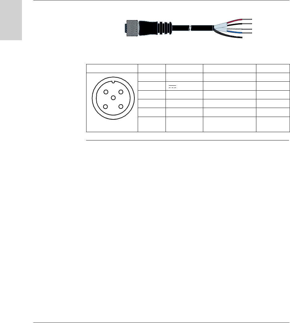
Connecting the Station
Connector
Wiring
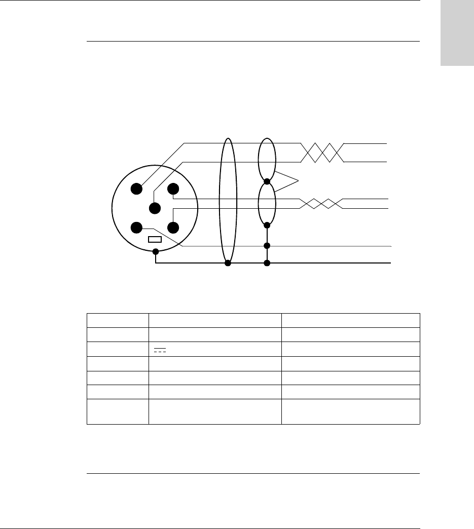
The stations are equipped with a single male M12 A-coded connector for the power
supply and communication bus.
The communication bus wires are shielded separately from the power supply
cables, to avoid interference carried by the power supply causing disturbance on the
communication wires.
Station M12 connector pinout:
* : Use a PELV power supply and fused protection (1 A). The power supply used
must be class II according to VDE 0106 (eg: Phaseo ABL 7/8 range from
Telemecanique) and the 0V must be grounded.
Pin no. Signal Description
1 Drain (SHLD) Cable shielding
2 24 V Station power supply *
30 V 0 V
4 D0 RS 485
5 D1 RS 485
Connector
casing
Shielding Cable shielding
12
43
5
General cable shielding
Shielding in pairs
Male M12 connector Compact station

Installing the System
26 W916556690111 27/06/2007
English
Range of
Accessories
The TCS AMT31FP splitter box and the TCS Modbus/Uni-Telway cables supply
power to the XGCS stations and enable their quick, easy connection to the Modbus
network.
Description Reference
Splitter box for connecting up to three
XGCS stations:
Modbus/Uni-Telway
TCS AMT31FP
Modbus Ethernet TCP/IP (see manual
1655668 01)
XGS Z33ETH
Shielded cable, 5-way male/female M12
coding A, for Modbus/Uni-Telway RS485
connection between one TCS AMT31FP
splitter box and an XGCS station (or to
another splitter box).
TCS MCN1M1F1 (1 m/3.28 ft)
TCS MCN1M1F2 (2 m/6.56 ft)
TCS MCN1M1F5 (5 m/16.4 ft)
TCS MCN1M1F10 (10 m/32.8 ft)
Shielded cable, 5-way female M12 coding
A/flying leads, for Modbus/Uni-Telway
RS485 connection between one
TCS AMT31FP splitter box and one
TSX SCA50 connector.
TCS MCN1F2 (2 m/6.56 ft)
TCS MCN1F5 (5 m/16.4 ft)
TCS MCN1M1F10 (10 m/32.8 ft)
Cable, 4-way female M12 coding A/flying
leads, for the splitter box power supply.
XGS Z08L2 (2 m/6.56 ft)
XGS Z08L5 (5 m/16.4 ft)
XGS Z08L10 (10 m/32.8 ft)
Shielded cable, 5-way female M12 coding
A/Mini-DIN, for connecting TCS AMT31FP
splitter boxes to a Telemecanique PLC.
TCS MCN1F9M2P (2 m)
Shielded cable, 5-way female M12 coding
A/15-way SUB-D, for connecting
TCS AMT31FP splitter boxes to a
TSX SCA62 connector.
TCS MCN1FQM2 (2 m/6.56 ft)
Shielded 5-way M12 coding A connectors
with screw terminals
FTX CN12F5 (female)
FTX CN12M5 (male)
Tee, 5-way female M12/5-way female
M12 + 5-way male M12 coding A
TCS CTN011M11F
120 Ω line terminator, M12 male coding A.
For Modbus and CANopen only,
unusable on Uni-Telway
FTXCNTL12
Ositrack
24V
IN OUT

Installing the System
W916556690111 27/06/2007 27
English
Wiring a Modbus/Uni-Telway Network
Network
Architecture
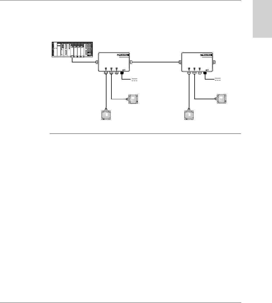
Example of a Modbus/Uni-Telway network assembly:
Cable Sizes The cables used for this assembly must comply with the rules for the maximum
lengths of buses and tap-offs.
Maximum Bus
Length
With Ositrack Compect stations, the maximum length of the bus (LA + LB + LC)
depends on the network speed and the protocol :
On modbus, for lengths of more than 100 m (328.083 ft), it is recommended that
a line terminator is added at the ends of the network (end of segment LC in the
example).
On Uni-Telway, and for the lenghts above, it’s not necessary to add a line
terminator at the ends of the network. Never use FTX CNTL12 line terminator.
Maximum Tap-
Off Length
The maximum tap-off (L1, L2 and L3) length is 10 meters (32.8 ft).
LB
L1 L2 L3
24 V
Ositrack
24V
IN OUT
Ositrac k
24V
IN OUT
LA
24 V
LC
Network Network speed Maximum length of the bus with
Ositrack Compect stations
Modbus 9600 Bauds 1000 m (3280.83 ft)
19200 Bauds 500 m (1640.41 ft)
Uni-Telway 9600 Bauds 500 m (1640.41 ft)
19200 Bauds 250 m (820.21 ft)

Installing the System
28 W916556690111 27/06/2007
English
Connection to a
Telemecanique
PLC using
Modbus/Uni-
Telway
Direct connection:
Connection via a TSX SCA62:
TCS MCN1F9M2P
Premium
TCS MCN1M1F•
Ositra ck
24V
IN OUT
XGS Z08L•
24 V
TSX SCA•00
TSX SCA62
Ositra ck
24V
IN OUT
TCS MCN1M1F•
XGS Z08L•
TCS MCN1FQM2 24 V
Premium

Installing the System
W916556690111 27/06/2007 29
English
Connection of
Line Terminators
on Modbus
Using long network cables can generate signal distortion. The installation of line
terminators corrects these distortions.
A line terminator near the station (M12 tee) may be necessary, depending on the
quality of the cables and the EMC environment.
Examples:
The line terminator can be positioned differently depending on the distance between
the station and the splitter box.
TCS CTN011M11F FTX CNTL12
Ositr ack
24V
IN OUT
Ositrack
24V
IN OUT
+
FTX CNTL12
L > 2 m (6.56 ft) L < 2 m (6.56 ft)
24 V 24 V
Premium
M340
Premium
M340

Installing the System
30 W916556690111 27/06/2007
English
Wiring an Ethernet Modbus TCP/IP network
Connection
Diagram
Example of a Modbus Ethernet TCP/IP network setup with splitter box
XGS Z33ETH:
The default transmission speed of the Ethernet splitter box (XGS Z33ETH) is 57600
bauds. This speed allows a total bus length of 160 m (524.93 ft) between the splitter
box and the stations.
Example:
3 x 50 meters (164.04 ft) for 3 stations
2 x 80 meters (262.46 ft) for 2 stations
Using long network cables can generate signal distortion. The installation of line
terminators corrects these distortions.
A line terminator near one of the stations (M12 tee) may be necessary, depending
on the quality of the cables and the EMC environment.
Switch
Ethernet
TCS MCN1M1F•
XGSZ33ETH
TCS ECL1M3M••S2
Ethernet
24 V
Premium
M340
24V
Ositrack
PI
scitsongaiD sutatS
ytivitca .htE
01/ spbM 001rewoP
XGSZ33ETH
24 V
24V
Ositrack
PI
scitsongaiD sutatS
ytivitca .htE
01/ spbM 001rewoP

Installing the System
W916556690111 27/06/2007 31
English
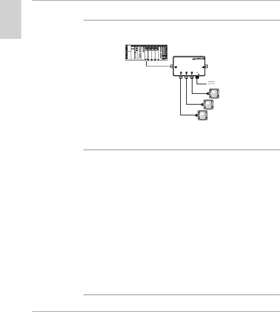
Connecting the TCS AMT31FP splitter box
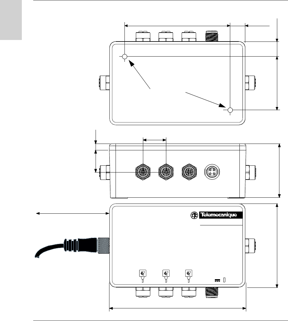
Description Description of the splitter box:
No. Description
1 Green LED indicating voltage present
2 Sub-base to another splitter box (Network OUT)
3 24 V power supply sub-base
4 3 Ositrack compact station sub-bases
5 Sub-base to a PLC or another splitter box (Network IN)
1
2
4
5
3
Installing the System
32 W916556690111 27/06/2007
English
Dimensions Dimensions in mm (inches):
6,1 (0.24)
51 (2)
Ositrack
24V
IN OUT
21 (0.82)
80 (3.15)
130 (5.12)
22 (0.86)
50 (1.97)
115 (
4.53
)
15 (0.59)
15 (0.59)
2 x M4x30 mm
> 110 (4.33)
Installing the System
W916556690111 27/06/2007 33
English
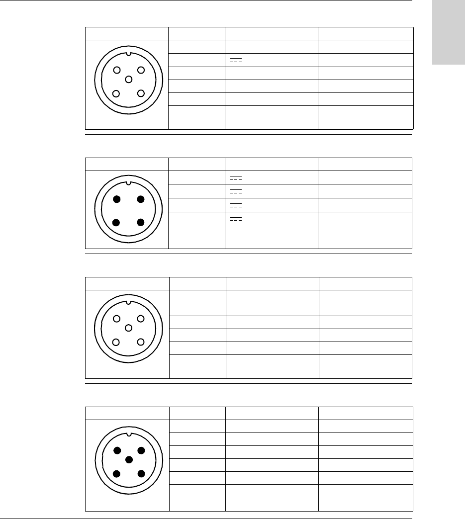
Sub-Base to
Station Wiring
Pinout of the female M12 coding A sub-base (station link):
Sub-Base to
Power Supply
Wiring
Pinout of the male M12 coding A sub-base (power supply):
Wiring for Sub-
Base to Another
Splitter Box
Pinout of the female M12 coding A sub-base (Network OUT):
Sub-base to PLC
Wiring
Pinout of the male M12 coding A sub-base (Network IN):
Diagram Pin no. Signal Description
1 Drain (SHLD) Cable shielding
2 24 V Station power supply
3 0 V/ GND 0 V
4 D0 RS 485
5 D1 RS 485
Connector
casing
Shielding Cable shielding
2
1
3
5
4
Diagram Pin no. Signal Description
1 24 V Power supply +
2 24 V Power supply +
3 0 V Power supply -
4 0 V Power supply -
12
34
Diagram Pin no. Signal Description
1 Drain (SHLD) Cable shielding
2- Reserved
3 0 V / GND 0 V
4 D0 RS 485
5 D1 RS 485
Connector
casing
Shielding Cable shielding
2
1
3
5
4
Diagram Pin no. Signal Description
1 Drain (SHLD) Cable shielding
2- Reserved
3 0 V / GND 0 V
4 D0 RS 485
5 D1 RS 485
Connector
casing
Shielding Cable shielding
12
3
5
4
Installing the System
34 W916556690111 27/06/2007
English
Connection
Recommen-
dations
Connection recommendations for TCSMCN1F• cables:
Connection:
Diagram Pin no. Signal Description Color of wire
1 Drain (SHLD) Cable shielding -
2 24 V Station power supply Red
3 0 V / GND 0 V Black
4 D0 RS 485 White
5 D1 RS 485 Blue
Connector
casing
Shielding Cable shielding -
2
1
3
5
4

W916556690111 27/06/2007 35
English
3
Setting the System Parameters
Presentation
Aim of this
Chapter
This chapter describes the station parameter settings for network communication
with the control system.
What's in this
Chapter?
This chapter contains the following topics:
Topic Page
Setting the Station Parameters 36
Setting the PLC Parameters 40

Setting the System Parameters
36 W916556690111 27/06/2007
English
Setting the Station Parameters
General Each time the station is powered up, it automatically detects the format and network
speed.
The stations are supplied configured at network address 1 with a transmission
speed of 19200 Bauds.
Before use, it is essential to configure the network address of each station. Stations
can be addressed in two ways:
Either using the XGS ZCNF01 configuration badge (supplied with the station)
Or via the network (Modbus or Uni-Telway write command).
Setting the System Parameters
W916556690111 27/06/2007 37
English
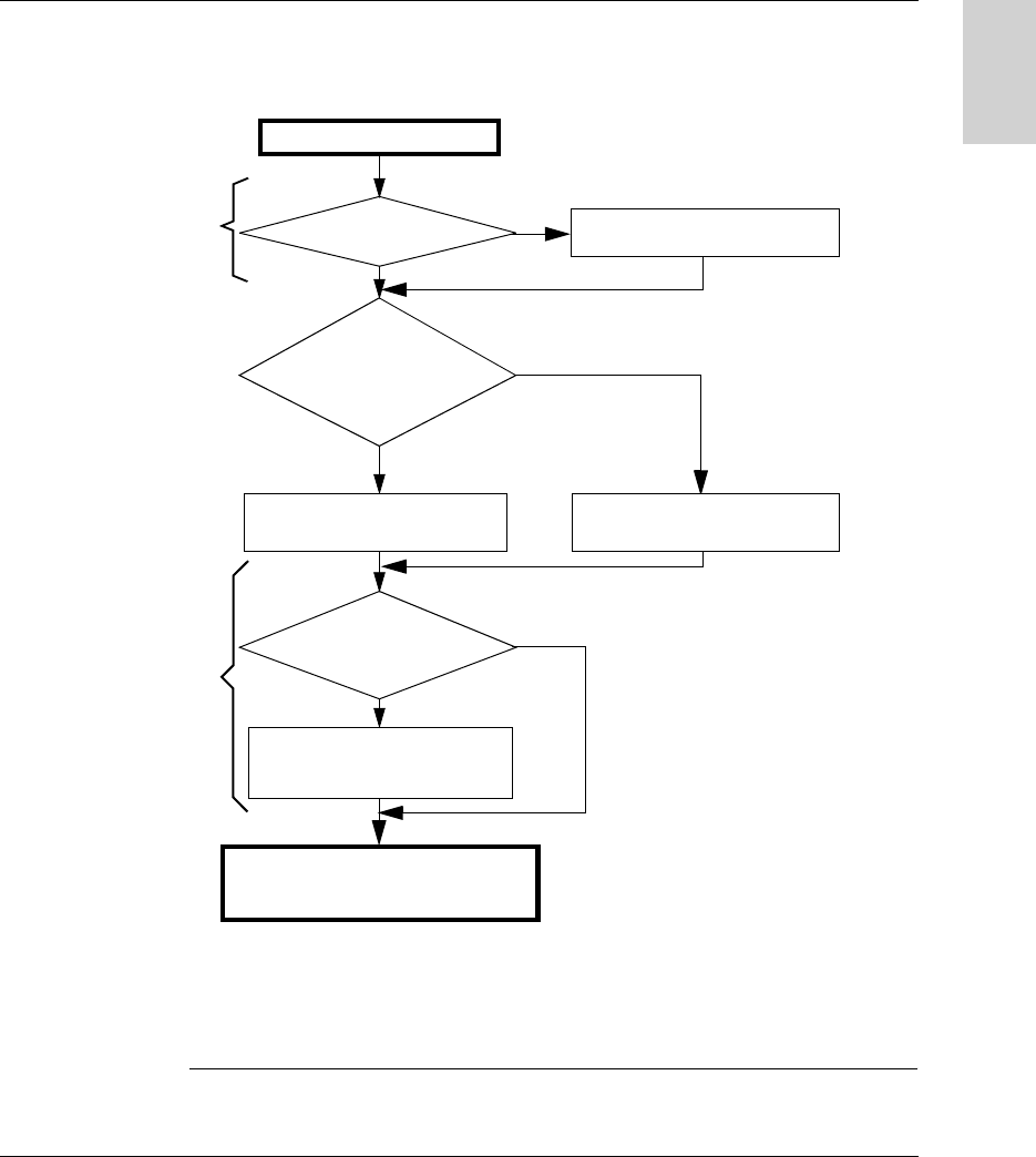
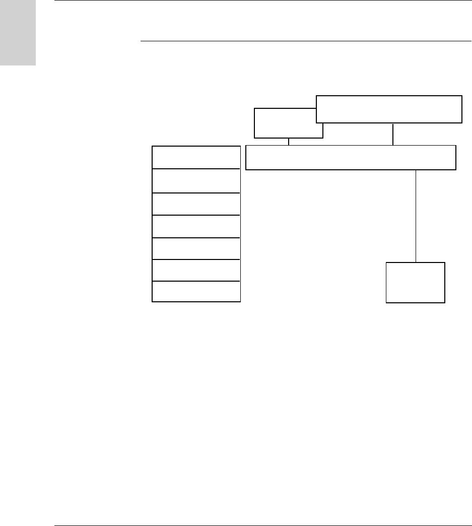
Station
Initialization
The station start-up cycle is as follows:
At all times, if the station does not recognize three successive frames, it returns to
Auto-configuration mode.
Advice: Launch a reading loop of the station status word to allow the auto-
configuration of the station. As soon as the station answers, it is ready to operate.
SeeResult of the
Self-Test, p. 86
SeeAddress
Configuration via the
XGS ZCNF01
Badge, p. 38
8 Red/Green flashes
Last
valid configuration
Await
char. on the
network (7 s): LED
COM orange
No
Yes
Addressing
badge (XGS
ZCNF01)
No
Normal tag
Station ready to operate
(read/write on tag)
Auto-configuration
(protocol, speed, etc)
Address configuration
Power-up
Yes
The station must be supplied
with power and connected to
the network
Self-test OK?
No
Yes
Setting the System Parameters
38 W916556690111 27/06/2007
English
Address
Configuration via
the XGS ZCNF01
Badge
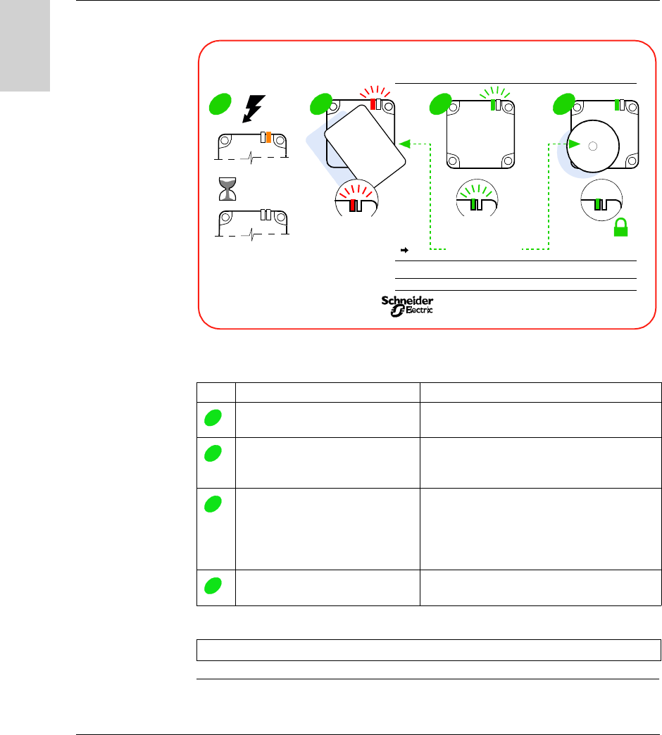
The addressing procedure is described on the back of the configuration badge:
Configuring the station network address:
Step Action Result
Power up the Station
Wait for 5 seconds
Station self-test
Place the configuration badge in
front of the station.
Count the number of flashes.
The TAG LED flashes red.
Each red flash emitted corresponds to one
increment of the network address.
Remove the configuration badge
when the required network address
is reached.
The TAG LED flashes green. The number of
green flashes emitted corresponds to the
network address that has just been configured.
It is then possible to restart the configuration at
step 2.
Place a "normal" (XGHB) tag in
front of the station.
The configured network address is confirmed
and saved in the station.
Note: The network address range is from 1 to 15.
OK
NO
Address
Configuration
Badge
X
3
3
=
X
3
address
3
=
OK
1s
5s
1 2 3 4
XGS-ZCNF01
Address Configuration Badge
for
RFID
Compact Station
France 0604
Tag
addresses range 1 15
ex:
=
address
3 flashes 3 flashes
1
2
3
4

Setting the System Parameters
W916556690111 27/06/2007 39
English
Addressing via
the Network
The station address can be modified using a standard word write request (see
Station Memory Zone, p. 43).
The request will be sent to the known station address. The new address is
immediately effective.
When the execution report has been sent, the TAG LED will emit as an echo a
number of green flashes equivalent to the address that has just been configured.
Note: The network address range is from 1 to 15.
Setting the System Parameters
40 W916556690111 27/06/2007
English
Setting the PLC Parameters
Electrical
Characteristics
The network interface module supports 2-wire RS 485.
Communication
Configuration for
Modbus and Uni-
Telway
The Modbus / Uni-Telway communication parameters that define the frame can be
configured in various ways.
The Ositrack compact station parameters are defined so that they support the
following values:
Parameter Value
Modbus Uni-Telway
Mode RTU -
Parity Automatic detection (even, odd, no parity) Odd
Stop bit 1 1
Data bit 8 8
Data rate Automatic detection (9600... 115200 bauds) Automatic detection (9600... 19 200 bauds)
WARNING
UNINTENDED OPERATION
Check that all the devices on the network are communicating using the appropriate
parameters. A disparity between the parameters could result in unintended
operation of the inputs, outputs and the other devices. The hardware configuration
may cause unintended equipment operation.
Failure to follow this instruction can result in death, serious injury, or
equipment damage.


Operating Principles
42 W916556690111 27/06/2007
English
Memory Zones
Presentation The addressing memory zone is divided into two zones:
The tag memory zone
The station memory zone
Definition of the word address zones used:
Tag
memory zone
%MW0
%MW32767
0000h
7FFFh
Station
memory zone
%MW65535
8000h
FFFFh
%MW32768

Operating Principles
W916556690111 27/06/2007 43
English
Station Memory Zone
General
Description
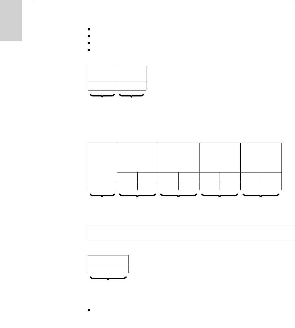
Definition of the word address zones used:
System Zone Modifications to values in this zone are taken into account by the station
immediately.
Composition of the system zone:
* : R = Read - W = Write
Word addresses
in hexadecimal format
Non-stored data Read-only
8000h
FFFFh
Zone reserved for the
station settings
Stored
data
Read-only
Read/
Write
Zone strictly
for internal
use. Not
accessible to
the user and not
documented
Station address
Parameters obtained by the
auto-baud function
UID (Unique Identifier) read
Tag counters on 16 bits
Tag present + RFID protocol +
type of tag
Type of access
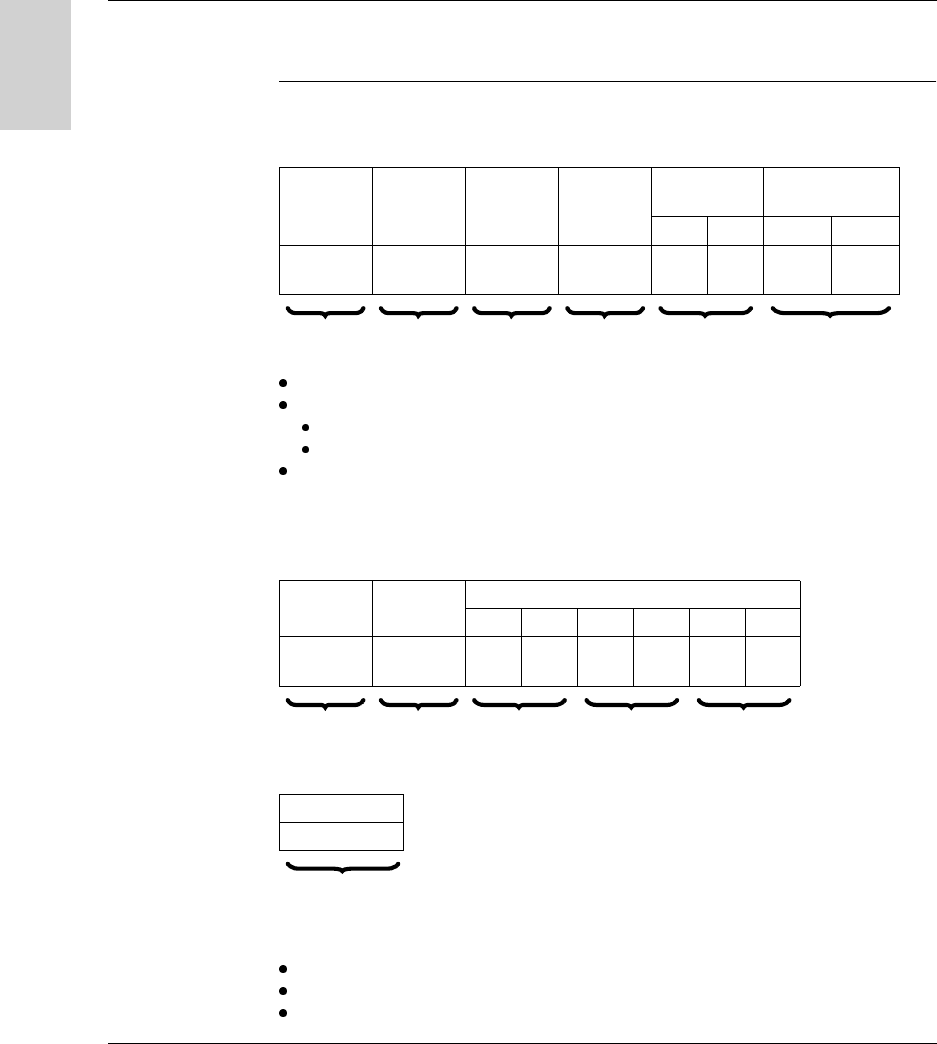
Object no. Description Mode *
8000h Tag family present/Tag system flags R
8001h Tag counter R
8002h...8009h UID R
8018h Station address R/W

Operating Principles
44 W916556690111 27/06/2007
English
Object 8000h Status:
Object 8001h Tag counter:
Objects
8002h...8009h
UID:
Each tag has a different unique code (UID). This code is spread over 16 bytes.
MSB LSB
Tag family present
Indicates the tag family while it is
present. Reset when no longer present.
Tag system flags
Updated in real time.
Bit Bit
8 15693 0 (LSB) Tag present
9 Icode 1 Initial parameter-setting phase following
boot-up
A 14443A 2 Reserved
B 14443B 3 Reserved
C Inside 4 Reserved
D Reserved 5 Configuration badge present
E Reserved 6 Reserved
F (MSB) Reserved 7 Reserved
MSB LSB
Incremented each time there is a new tag. Reset at each time power-up.
MSB LSB
Updated each time there is a new tag and valid if tag present.

Operating Principles
W916556690111 27/06/2007 45
English
Object 8018h Station address:
Read request:
Response to the read request:
Write request:
MSB LSB
0 Station address
Write request: Result
MSB LSB
0...1E Station address No action
1F Station address The new station address is immediately effective.

Operating Principles
46 W916556690111 27/06/2007
English
Tag Memory Zone
Automated
Production Tag
These tags are addressed according to the table below and are accessible in Read/
Write mode.
The station can read any tag in the XGHB range (automatic detection of the tag
type).
(1): Reserved addresses
(2): Reject if higher address requested
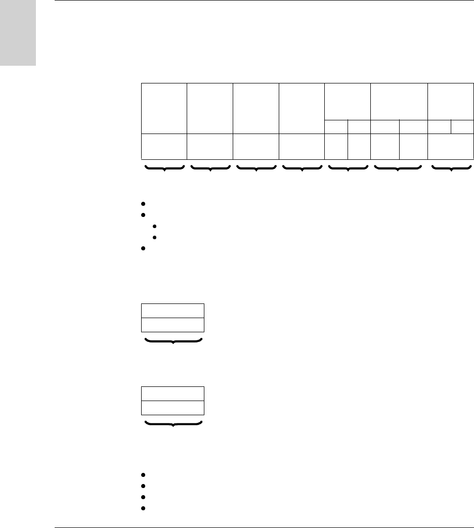
Type of tag XGH
B90E340
XGH
B221346
XGH
B320345
XGH
B211345
XGH
B444345
XGH
B445345
256 bytes 256 bytes 112 bytes 256 bytes 3408 bytes 13632
bytes
Addresses Dec. Hex. Dec. Hex. Dec. Hex. Dec. Hex. Dec. Hex. Dec. Hex.
000000000 0 0 0
to to to to to to to to
127 7F 127 7F 55 37 127 7F to to
(1) (1) (1) (1) to to
1703 6A7
(2)
6815 1A9F
(2)
CAUTION
UNINTENDED OPERATION
Do not use XGH B445345 and XGH B444345 tags in the same application.
Once the station has automatically detected the XGH B445345 tag, it will no longer
recognize the XGH B444345 tag.
Failure to follow this instruction can result in injury or equipment damage.

Operating Principles
W916556690111 27/06/2007 47
English
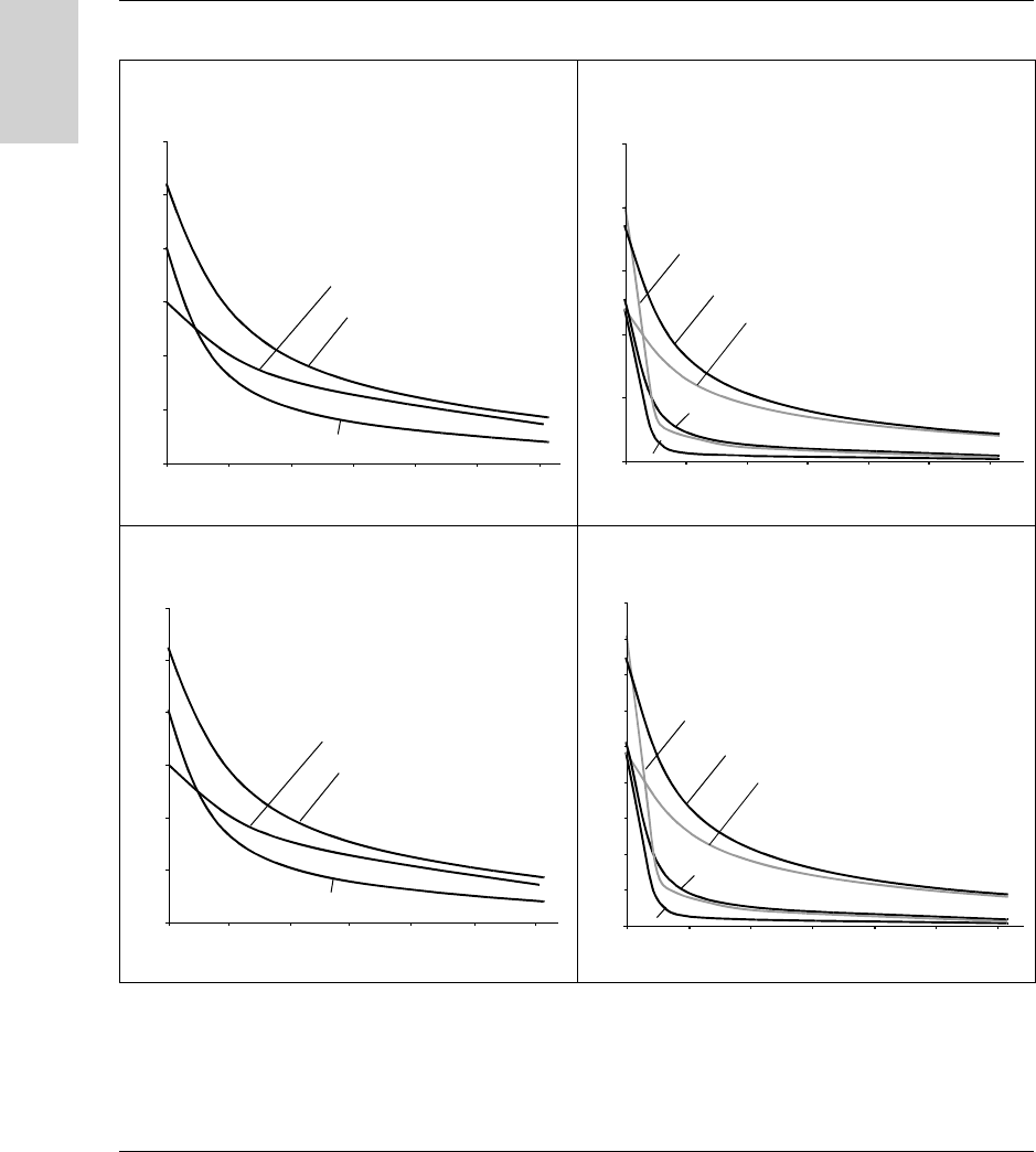
Read/Write Time The read/write times are calculated using the following formulas:
N: Number of words
The following table gives the read/write speeds:
Charts showing the access times for selecting stations and tags:
Note: The access times given do not take the transfer times on the network into
account.
Access time (ms) XGH
B90E340
XGH
B221346
XGH
B320345
XGH
B211345
XGH
B444345
XGH B445345
Read time 12+0.825xN 12+0.825xN 12+0.825xN 12+0.825xN 9.25+0.375xN 16.25+0.375xN
Write time 20+11.8xN 20+11.8xN 12+5.6xN 19+4.1xN 13+0.8xN 20+0.8xN
XGH B90E340
XGH B221346
XGH B320345
XGH B211345
XGH B444345
XGH B445345
XGH B90E340
XGH B221346
XGH B320345
XGH B211345
XGH B445345
XGH B444345
Access
Time
(ms)
READ
Access
Time
(ms)
WRITE
Number of Words
Number of Words
0
20
40
60
80
100
120
20 40 60 80 100 120
020406080100
120
0
0
200
400
600
800
1000
1200
1400
1600
Operating Principles
48 W916556690111 27/06/2007
English
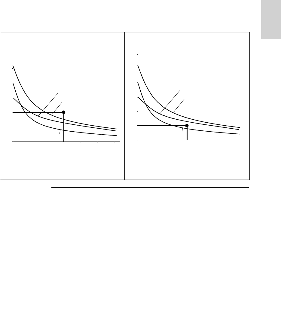
Charts showing the scrolling speeds for selecting stations and tags:
Key
READ WITH XGCS4 WRITE WITH XGCS4
READ WITH XGCS8 WRITE WITH XGCS8
Number of words
0
020406080100
120
50
100
150
200
250
300
3456
Tag moving speed (m/mn)
2
1
1 m/mn = 3.28 ft/mn
0
020406080100
120
50
100
150
200
250
Number of words
Tag moving speed (m/mn)
1
2
3
4
5-6
1 m/mn = 3.28 ft/mn
0
020406080100
120
100
200
300
400
500
600
Number of words
1
3 456
2
Tag moving speed (m/mn)
1 m/mn = 3.28 ft/mn
0
0 20 40 60 80 100 120
50
100
150
200
250
300
350
400
450
Number of words
Tag moving speed (m/mn)
1
2
3
4
5-6
1 m/mn = 3.28 ft/mn
XGH B90E340
XGH B221346
XGH B320345
XGH B211345
XGH B444345
XGH B445345
3
4
5
6
1
2
Operating Principles
W916556690111 27/06/2007 49
English
Example of using the charts:
On an assembly line, the scrolling speed is 100 m/min (328 ft/mn). The application
requires 60 words to be read.
READ WITH XGCS4 READ WITH XGCS8
The XGCS4 station cannot be used. No Ositrack tag can
be read under these conditions (Speed/No. of words).
The XGCS8 station can be used. Only XGH B444345 and
XGH B445345 tags meet the requirements (Speed/No. of
words).
Number of words
0
020406080100
120
50
100
150
200
250
300
3456
Tag moving speed (m/mn)
2
1
1 m/mn = 3.28 ft/mn
0
020406080100
120
100
200
300
400
500
600
Number of words
1
3 456
2
Tag moving speed (m/mn)
1 m/mn = 3.28 ft/mn

Operating Principles
50 W916556690111 27/06/2007
English

W916556690111 27/06/2007 51
English
5
Communicating with the Uni-
Telway Protocol
Presentation
Aim of this
Chapter
This chapter describes the Uni-Telway protocol communication principle (Only from
version V3.8 of the station).
What's in this
Chapter?
This chapter contains the following topics:
Topic Page
General 52
Requests 54
Programming 66

Communicating with the Uni-Telway Protocol
52 W916556690111 27/06/2007
English
General
General In the Telemecanique communication architecture, all message exchanges are
performed in point-to-point mode between two logical entities (client and server).
These logical entities must be identified by an address which is unique within the
whole environment.
These addresses (sender address and destination address) are transmitted with
each message.
Message structure:
In the Telemecanique addressing system, based on the TSX7 PLC architecture,
these addresses (sender and destination) are coded on 5 bytes:
network number
station number
gate number
module number
channel number
The network number and station number bytes are used to identify the devices
connected to the Uni-Telway network.
Exchange
Principle
The UNI-TE requests supported by the Ositrack system enable the following
operations:
data exchanges with the tag in direct operating mode using standard requests:
WRITE OBJECTS
READ OBJECTS
WRITE WORD
READ WORD
INIT
access to data specific to the system (product version, protocol version,
communication quality, etc) using standard requests:
IDENTIFICATION
PROTOCOL VERSION
STATUS
MIRROR
READ COUNTERS
CLEAR COUNTERS
SENDER ADDRESS DESTINATION ADDRESS MESSAGE
Note: The Ositrack compact stations does not accept more than one request at the
same time. A negative acknowledgement (nack) is returned if a request is received
while the previous one is not yet finished.

C om m unicating w ith the U ni-T elw ay P rotocol
54 W916556690111 27/06/2007
English
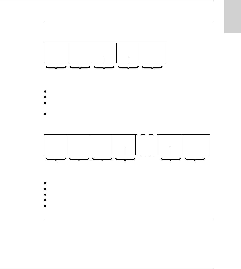
Request
Reading Objects This request is used to read n objects.
Request:
Segment: 01h or 68h = physical address of words
Specific byte:
00h = request for deferred response if tag missing
06h = request for immediate response
Object address: Address of the first word to be read.
Station response:
Positive response:
Negative response (eg: with byte 06h if tag missing):
Causes of rejection:
Unknown tag
Inadequate access rights
Unknown object
Request
code
Category
code
Segment Specific
byte
Object
address
Number of
objects to be read
Pf PF Pf PF
36h/54 00h 01h
68h
00h
06h
1 byte 1 byte 1 byte 1 byte 2 bytes 2 bytes
Response
code
Specific
byte
Data
Pf PF Pf PF Pf PF
66h/102 00h
06h
1 byte 1 byte 2 bytes n*2 bytes 2 bytes
Response code
FDh/253
1 byte

Communicating with the Uni-Telway Protocol
W916556690111 27/06/2007 55
English
Address of the last object outside limits
Indexed address outside limits
Tag missing if specific byte = 06h.
Note: The reading is limited to 120 words maximum.
Communicating with the Uni-Telway Protocol
56 W916556690111 27/06/2007
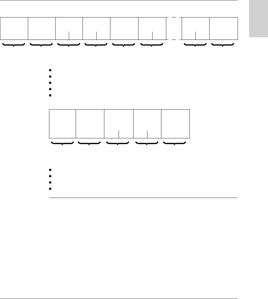
English
Writing Objects This request is used in direct operating mode to write n words to the tag or station
memory zones.
In this operating mode, all the data processing is carried out by the PLC or the
computer.
Request:
Segment: 01h or 68h = physical address of words
Specific byte:
00h = request for deferred response if tag missing
06h = request for immediate response
Object address: Address of the first word to be written.
Station response:
Positive response:
Negative response (eg: with byte 06h if tag missing):
Causes of rejection:
Unknown tag
Inadequate access rights
Unknown object
Address of the last object outside limits
Request
code
Category
code
Segment Specific
byte
Object
address
Number of
object to be
written
Data
Pf PF Pf PF Pf PF
37h/55 00h 01h
68h
00h
06h
Series of
words
1 byte 1 byte 1 byte 1 byte 2 bytes 2 bytes n*2 bytes
Response code
FEh/254
1 byte
Response code
FDh/253
1 byte
Communicating with the Uni-Telway Protocol
W916556690111 27/06/2007 57
English
Writing not checked
Indexed address outside limits
Tag missing if specific byte = 06h.
Read a Word This request is used for direct access to words in an addressable memory zone.
Request:
Station response:
Positive response:
Negative response:
Causes of rejection:
Inadequate access rights
Unknown object
Word number address outside limits
Tag missing.
Write a Word This request is used for direct access to words in an addressable memory zone.
Note: The writing is limited to 120 words maximum.
Request
code
Category
code
Word number
Pf PF
04h/04 00h
1 byte 1 byte 2 bytes
Response
code
Value
Pf PF
34h/52
1 byte 2 bytes
Response code
FDh/253
1 byte

Communicating with the Uni-Telway Protocol
58 W916556690111 27/06/2007
English
Request:
Station response:
Positive response:
Negative response:
Causes of rejection:
Unknown request
Inadequate access rights
Word number outside limits
Tag missing
Tag not initialized.
Request
code
Category
code
Word number Word value
Pf PF Pf PF
14h/20 00h
1 byte 1 byte 2 bytes 2 bytes
Response code
FEh/254
1 byte
Response code
FDh/253
1 byte

Communicating with the Uni-Telway Protocol
W916556690111 27/06/2007 59
English
INIT Request This request is used to cancel all current requests.
Request:
Station response:
Positive response:
Negative response:
Causes of rejection:
Unknown request
Inadequate access rights
Request code Category code
33h/51 00h
1 byte 1 byte
Response code
63h/99
1 byte
Response code
FDh/253
1 byte

Communicating with the Uni-Telway Protocol
60 W916556690111 27/06/2007
English
MIRROR
Request
This service is used to test the system and the communication path.
The client sends a sequence which the server sends back to the client.
Request:
Station response:
Positive response:
Request code Category code Data
FAh/250 00h Series of bytes (maximum 32)
1 byte 1 byte n bytes
Request code Data
FBh/251 Series of bytes sent by the request
1 byte n bytes
Note: There is never a negative response.

Communicating with the Uni-Telway Protocol
W916556690111 27/06/2007 61
English
IDENTIFI-
CATION Request
This request is used to obtain the product type and product version as a response.
Request:
Station response:
Positive response:
(1) : Version number in BCD format.
(2) : Product identification: "XGC-S-V3.8 "
Negative response:
Causes of rejection:
Unknown request
Inadequate access rights
Request code Category code
0Fh/15 00h
1 byte 1 byte
Response
code
Category
code
Product
sub-type
Product
Version
Length Product Identification
3Fh/63 24h/36 01h (1) 0Bh (2)
1 byte 1 byte 1 byte 1 byte 1 byte n bytes
Response code
FDh/253
1 byte

Communicating with the Uni-Telway Protocol
62 W916556690111 27/06/2007
English
PROTOCOL
VERSION
Request
This service is used to identify the version and any parameters of the application
protocol which is used for the conversation. In this request, the client provides the
versions of the application protocol which it supports, the maximum message size,
the size of the request file, etc. The server will then send back its own specifications.
This then enables the client to send requests in a format and size which is known to
both parties.
Request:
(1) : number of versions supported.
(2) : list of versions supported.
Station response:
Positive response:
(1) : 10h for version V 1.0.
Negative response:
Causes of rejection:
Unknown request
Inadequate access rights
Request
code
Category
code
Max. message
size
Length (1) Version (2)
Pf PF
30h/48 00h 20h 00h 01h Series of bytes
1 byte 1 byte 2 bytes 1 byte n bytes
Response
code
Max. message
size
Length Version Request file size
Pf PF Pf PF
60h/96 80h 00h 01h (1) 00h 00h
1 byte 2 bytes 1 byte 1 byte 2 bytes
Response code
FDh/253
1 byte

Communicating with the Uni-Telway Protocol
W916556690111 27/06/2007 63
English
STATUS Request The station provides its status in the response.
Request:
Station response:
Positive response:
Status mask: Bit string. Only those current status bits whose bit of the same rank in
"status mask" is at 1 are significant.
Example:
Negative response:
Causes of rejection:
Inadequate access rights (request in process)
Request code Category code Detail required
31h/49 00h 00h
1 byte 1 byte 1 byte
Response code Current status Status Mask
61h/97 (1) (2)
1 byte 1 byte 1 byte
Response code
FDh/253
1 byte
Status Mask (2) Current status (1)
F
00000001
0
TAG present
Reserved
Communicating with the Uni-Telway Protocol
64 W916556690111 27/06/2007
English
READ COUNTER
Request
Each station manages a log of link faults (character error, frame error, protocol
error), and counts 4 types of error in counters (16-bit words):
number of messages sent and not acknowledged
number of messages sent and refused
number of messages received and not acknowledged
number of messages received and refused
Request:
Station response:
Positive response:
Negative response:
Causes of rejection:
Unknown request
Request
code
Category
code
A2h/162 00h
1 byte 1 byte
Response
code
Number of
messages sent
and not
acknowledged
Number of
messages
refused
Number of
messages
received and not
acknowledged
Number of
messages
refused
Pf PF Pf PF Pf PF Pf PF
D2h/210
1 byte 2 bytes 2 bytes 2 bytes 2 bytes
Note: There is no counter overflow. The counters remain frozen at address 7FFFh
(32767) until they are reset by sending a clear counter request (A4h).
Response code
FDh/253
1 byte

Communicating with the Uni-Telway Protocol
W916556690111 27/06/2007 65
English
Inadequate access rights
CLEAR
COUNTER
Request
This request is used to clear the 4 error counters of a device to zero.
Request:
Station response:
Positive response:
Negative response:
Causes of rejection:
Unknown request
Inadequate access rights
Request code Category code
A4h/164 00h
1 byte 1 byte
Response code
FEh/254
1 byte
Response code
FDh/253
1 byte
Communicating with the Uni-Telway Protocol
66 W916556690111 27/06/2007
English
Programming
Application
Example
A splitter box and a Premium PLC are connected to a Uni-Telway network.
Read 10 words
under PL7 PRO
(READ_VAR
command)
Read 10 words at tag address 0.
The Ositrack compact station is at address 1 on the TSX SCY 21601 card of
PREMIUM PLC (slot 3, channel 0).
(* Description *)
(* %MW : Type of object to be read = internal word *)
(* %MD480 : Address of the first word to be read in the tag *)
(* 10 : Number of objects to be read *)
(* %MW600:10 : Table containing the value of the objects to be
read *)
(* %MW470:4 : Management parameters *)
%MD480 : = 0;
IF NOT %MW470:X0 THEN
(* send request and store result in %MW600:10 *)
READ_VAR(ADR#3.0.1, ’%MW’, %MD480, 10, %MW600:10, %MW470:4);
END_IF;
Ositr ack
24V
@ 2
@ 4
@ 3
24 V

Communicating with the Uni-Telway Protocol
W916556690111 27/06/2007 67
English
Write 10 Words
under Unity
(WRITE_VAR
command)
Write 10 words starting at tag address 16#100.
The Ositrack compact station is at address 1 on the TSX SCY 21601 card of a
PREMIUM PLC (slot 3, channel 0).
(* Description *)
(* %MW : Type of object to be written = internal word *)
(* %MD480 : Address of the first word to be written to the tag
*)
(* 10 : Number of objects to be written *)
(* %MW600:10 : Table containing the value of the objects to be
written *)
(* %MW470:4 : Management parameters *)
%MD480 : = 16#100;
IF NOT %MW470:X0 THEN
(* send request to write data to the tag *)
WRITE_VAR(ADR#3.0.1, ’%MW’, %MD480, 10, %MW600:10, %MW470:4);
END_IF;

Communicating with the Uni-Telway Protocol
68 W916556690111 27/06/2007
English
Write 10 words
(SEND_REQ
command)
Comment : (%MW471 = 0 if exchange correct)
Send a request:
(* Description *)
(* %MW480 : Lo specific byte Lo segment *)
(* %MW481 : Address *)
(* %MW482 : No. of objects to be written *)
(* %MW483 : Value of 1st word *)
(* %MW492 : Value of 10th word *)
(* %MW473 : 26 bytes *)
(* %MW600 : Reception table *)
%MW480 : =16#0001;
%MW481 : =16#0100;
%MW482 : =16#000A;
%MW483 : =1st word;
%MW492 : =10th word;
%MW473 : =16#001A;
%MW600 : =reception table;
IF NOT %MW470:X0 THEN
(* send request to write data to the tag *)
SEND_REQ(ADR#3.0.1, 16#0037, %MW480:3, %MW600:1, %MW470:4);
END_IF;

Communicating with the Modbus Protocol
70 W916556690111 27/06/2007
English
General
Presentation With reference to the 7-layer OSI model, in which each layer performs a specific
service, the Modbus/JBUS protocol supports the following three layers:
Communication between a PLC (or computer) processor and the Ositrack identifi-
cation system using the Modbus/Jbus protocol is performed by exchanging
messages in both directions on a multidrop bus, via a serial link module with an
asynchronous link. Dialog between the higher processing levels and the Ositrack
system is of the question/answer type. The initiator (master station) sends the
messages to be executed to the Ositrack station (slave station), which answers after
execution. With the Modbus/Jbus protocol, the Ositrack station communicates in
RTU (Remote Terminal Unit) mode.
RS 485
System
Application (MODBUS/JBUS functions)
7 - Application
6 - Presentation
5 - Session
4 - Transport
3 - Network
2 - Data link
1 - Physical
Application program
OSI model
Communicating with the Modbus Protocol
W916556690111 27/06/2007 71
English
Information coding principle:
Exchange
Principles
Dialog between the PLC (or computer) and the Ositrack station is of the question/
answer type. The addressed slave answers every message sent by the master
station (PLC) immediately. The response time is dependent on:
The command processing time (which depends on the amount of data to be
exchanged and the type of tag)
The speed on the serial link
The length of the message
Connection For more detailed explanations on installation and connection, see Installing the
system, p. 13.
Characteristics 8 RTU bits
Coding system 8-bit binary code
Number of bits per character
Start bit
Significant bits
Parity
Stop bit
1
8
Even/Odd/No parity
1 / 2
Message structure
Message
Check
End of frame
MODBUS frame
CRC
3-character silence
Question
Answer
Question
Answer
Master
PLC
XG - X
Slave
station
XG - X
Slave
Station

Communicating with the Modbus Protocol
72 W916556690111 27/06/2007
English
Supported
Modbus
functions
The table below lists the supported Modbus functions:
Point-to-point
mode
When the PLC is connected directly to a compact station, this station can operate in
point-to-point mode. In this operating mode, the station responds to the requests
sent to address F8 as well as those sent to the station network address.
Broadcasting
mode
In this mode, the PLC sends requests to address 0 and the slaves do not respond
to the Modbus requests.
This mode is not authorized for Ositrack compact stations.
Code Type of request
Hex. Dec.
3 3 Read n words (1 ≤ n ≤ 123)
6 6 Write one word
8 8 Diagnostics
B 11 Read event counters
10 16 Write n words (1 ≤ n ≤ 123)
2B 43 ID
Communicating with the Modbus Protocol
W916556690111 27/06/2007 73
English
Requests
Read N Words This function is used to read objects (word, word string).
Read request:
Slave no: 01h to 0Fh in multidrop mode or F8h in point-to-point mode
Function code: 3h
Address of the first word: Corresponds to the address of the first word to be read
in the tag or the station (depending on the address)
Number of words: 1 ≤ N ≤ 123
Station response:
Slave no: Same as read request
Function code: Same as read request
Number of bytes read: 2 to 246
Value of the words read: 0000h to FFFFh
If there is no tag present, the station sends an error report (see Error
Messages, p. 78).
Slave no. Function
code
Address of
1st word
Number of
words
Check
3h Hi Lo Hi Lo
1 byte 1 byte 2 bytes 2 bytes 2 bytes (RTU
mode)
Slave no. Function
code
Number of
bytes read
Value of
1st word
Value of
last word
Check
3h or 4h Hi Lo Hi Lo
1 byte 1 byte 1 byte 2 bytes 2 bytes 2 bytes (RTU
mode)

Communicating with the Modbus Protocol
74 W916556690111 27/06/2007
English
Write One Word Write request:
Slave no: Same as read request
Function code: 6h
Word address: Same addressing field as for the read request
Word values: 0000h to FFFFh
Station response:
The response is an echo of the request, indicating that the value contained in the
request has been taken into account by the station.
Slave no. Function
code
Address of
word
Value of
word
Check
6h Hi Lo Hi Lo
1 byte 1 byte 2 bytes 2 bytes 2 bytes
(RTU mode)
Slave no. Function
code
Address of
word
Value of
word
Check
6h Hi Lo Hi Lo
1 byte 1 byte 2 bytes 2 bytes 2 bytes
(RTU mode)
Communicating with the Modbus Protocol
W916556690111 27/06/2007 75
English
Write N Words Write request:
Slave no: Same as read request
Function code: 10h
Number of words: 1 ≤ N ≤ 123
Number of bytes: Twice the number of words
Word values: 0000h to FFFFh
Station response:
Slave no.: Same as request
Function code: Same as request
Address of first word written: Same as request
Number of words written: Same as request
Slave no. Function
code
Address of
1st word
Number of
words
Number of
bytes
Value of 1st
word
Value of
last word
Check
10h Hi Lo Hi Lo Hi Lo Hi Lo
1 byte 1 byte 2 bytes 2 bytes 1 byte 2 bytes 2 bytes 2 bytes
(RTU mode)
Slave no. Function
code
Address of
1st word
written
Number of
words
written
Check
10h Hi Lo Hi Lo
1 byte 1 byte 2 bytes 2 bytes 2 bytes
(RTU mode)

Communicating with the Modbus Protocol
76 W916556690111 27/06/2007
English
Read diagnostic
counters code
08h
Functions 08h and 0Bh are used to check the PLC/station link and operate the event
counters (or diagnostic counters).
Request:
Station response:
Designation of the event counters:
Slave no. Function
code
Sub-function
code
Data Check
08h 00 Lo 00 00
1 byte 1 byte 2 bytes 2 bytes 2 bytes (RTU
mode)
Slave no. Function
code
Sub-function
code
Data Check
08h 00 Lo Hi Lo
1 byte 1 byte 2 bytes 2 bytes 2 bytes (RTU
mode)
Sub-
functions
Counter Description
0Bh 1 Number of requests correctly received by the station, whether or not
that station is affected
0Ch 2 Number of requests received with CRC errors
0Dh 3 Number of error messages sent back by the station (fault message),
or not sent back in the event of broadcasting
0Eh 4 Number of correct requests specifically addressed to the station
(apart from broadcasting)
0Fh 5 Number of broadcast requests received and correctly processed
10h 6 Number of executions not carried out due to communication with the
tag not being possible
12 7 Number of faults due to incorrect characters (format, parity, etc)
received by the station
00h - Mirror function
0Ah 8 Reset event counters function

Communicating with the Modbus Protocol
W916556690111 27/06/2007 77
English
Read events
code 0Bh
Functions 08h and 0Bh are used to check the PLC/station link and operate the event
counters (or diagnostic counters).
Read events code 0Bh sends back the number of requests received by the station
and correctly executed.
Request:
Response:
Identification
Request
Function 2Bh: This function is used to identify the station.
Read request:
* : MEI = Modbus Encapsulated Interface
Station response:
Slave no. Function
code
Check
0Bh
1 byte 1 byte 2 bytes (RTU
mode)
Slave no. Function
code
Counter Data Check
0Bh 0000Hi Lo
1 byte 1 byte 2 bytes 2 bytes 2 bytes (RTU
mode)
Slave no. Function code MEI * Read Device ID
code
Object ID
2Bh 0Eh 01h, 02h, 03h 00h
Index Object name & description Description Data type
0 (0000h) Manufacturer’s name TELEMECANIQUE ASCII string
1 (0001h) Product code
2 (0002h) Version number Vx.y (eg: V3.6)

Communicating with the Modbus Protocol
78 W916556690111 27/06/2007
English
Error Messages When an anomaly in the message (or during its execution) is detected by the station
to which it is addressed, the station sends back an error message to the master
system.
Syntax:
Slave no.: Same as request
Function code: Same as the function code and most significant bit of the byte set
to 1
Examples:
Function code of the error message after a read request:
83h = (80 + 03) or 84h = (80 + 04)
Function code of the error message after a write request:
90h = (80 + 10)
Error code:
1h: Unknown function code or incorrect request format
2h: Incorrect address or prohibited zone or protected zone or address outside the
tag memory zone
3h: Incorrect data. Too much or not enough data in the frame, or quantity = 0, or
data incompatible
4h: Execution fault (in read or write mode, or tag missing)
Slave no. Function
code
Error code Check
1 byte 1 byte 1 byte 2 bytes
(RTU mode)

Communicating with the Modbus Protocol
W916556690111 27/06/2007 79
English
Programming
Application
Example
A splitter box and a PLC are connected to a Modbus network.
Example of
Program in Unity
Program example: read station @ 2 status word.
Ositrack
24V
@ 2
@ 4
@ 3
24 V
Premium
M340
(*----- Step 2 -----------------------------------------*)
(* Read status word = test presence of badge station @ 2*)
IF NOT %MW702:X0 THEN
%MD1:=16#00008000;(* STATUS *)
READ_VAR(0.0.2,'%mw',%MD1,1,%MW800:1,%MW702:4);
END_IF;
Modbus address = 2
Communicating with the Modbus Protocol
80 W916556690111 27/06/2007
English
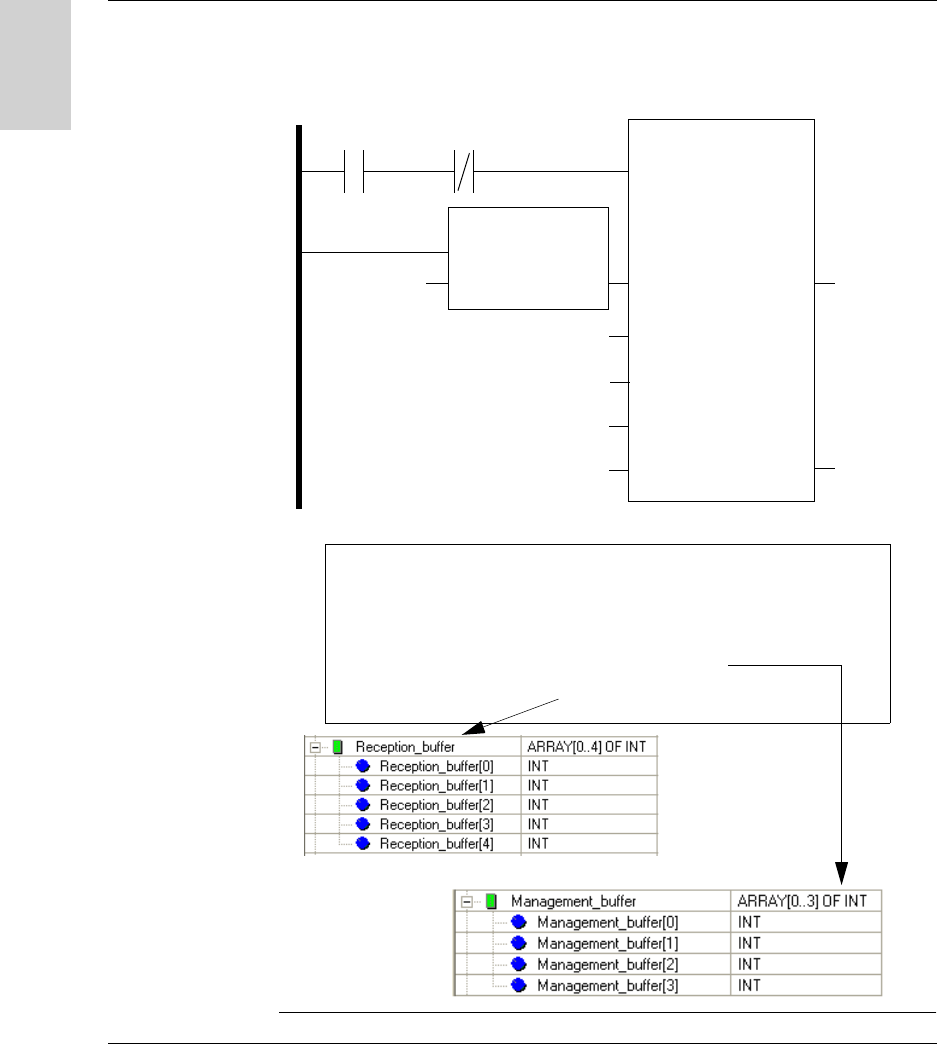
Example of
Program in
UNITY PRO
Program example: Read 5 words in the tag starting at word %MW 0 of the tag in
station @ 2
LADDER programming
Structured Text programming
%I0.3.1 %MW50.0
ADDR
EN
IN
EN0
OUT
‘0.0.2’
READ_VAR
EN
ADR
OBJ
‘%MW’
NUM
0
NB
5
GEST
‘%MW50:4
EN0
RECP
RECP ‘%MW50:4
‘%MW20:5
if % I3.0.1 and not Management_buffer[0].0 then
READ_VAR (adr := ADDR(’0.0.2’),
OBJ := ’%MW’,
NUM := 0,
NB := 5,
GEST := Management_buffer,
RECP => Reception_buffer);
end_if;
W916556690111 27/06/2007 81
English
7
Integration Tips
Tips
Protecting the
System
To protect the system against impacts, you can:
Embed the station in metal (see Mounting in metal, p. 22)
Embed the tag in metal (see Mounting in metal, p. 22)
Protect the station by making use of its ability to work through non-metallic
materials, for example:
Thermal
Protection
Avoid exposing the tags to radiating heat sources, such as infrared dryers.
Tag Station
Non-metallic material
Integration Tips
82 W916556690111 27/06/2007
English
Automation Synchronize the Read/Write operations with a sensor that indicates the presence of
the tag to the control system:
In case of processing errors (such as incorrect positioning of the tag or a
transmission error) provide for repetition of the request before switching to
"Fallback" mode (abandoning of the request and generation of an alarm).
Reading/Writing
Tag
Before initiating a tag Read/Write request, ensure that the tag is present using a
request to read the station STATUS word.
For more informations about the station’s sensing zone, see Sensing Zones, p. 21.
Tag Station
PLC
Tag presence sensor
CAUTION
UNINTENDED OPERATION
Only perform a write request when the tag is in the station’s sensing zone.
Do not use XGH B445345 and XGH B444345 tags in the same application.
Failure to follow this instruction can result in injury or equipment damage.
Integration Tips
W916556690111 27/06/2007 83
English
To make
maintenance
easier
Leave address 1 on the network free.
A new station (by default address 1) can then be added without disturbing the
network.
Example of addressing for ease of maintenance or replacement of stations:
Ositr ack
24V
IN OUT
Ositr ack
24V
IN OUT
@ 2
@ 3
@ 4
@ 5
24 V 24 V

Integration Tips
84 W916556690111 27/06/2007
English
W916556690111 27/06/2007 85
English
8
Diagnostics
Diagnosing a Fault
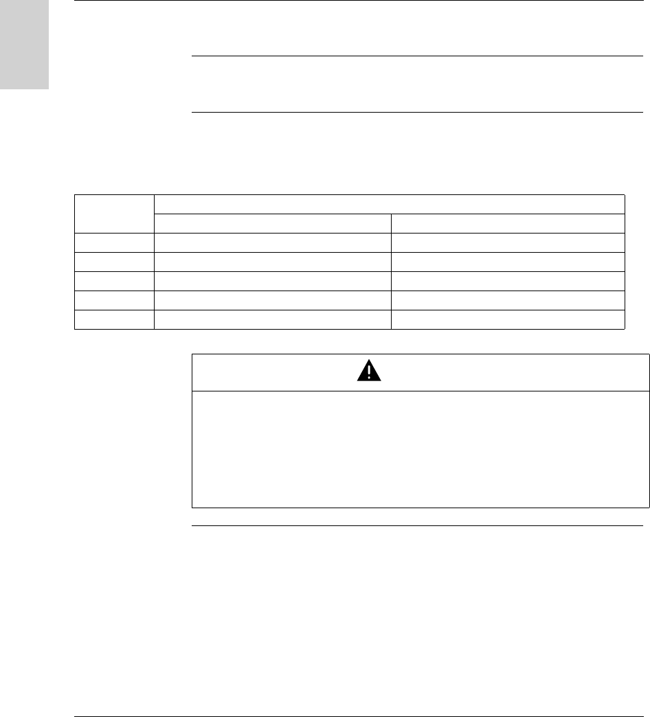
Meaning of the 2
LEDs
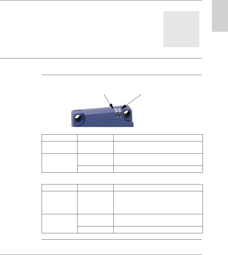
The 2 LEDs on the station display all the operating states of the station:
Description of the states of the TAG LED:
Description of the states of the COM LED:
Station status LED Description
Tag not present Series of green
flashes (periodic)
Number of flashes = network address of the station
Tag present Continuous green Tag present in the dialog zone
Read/Write functions activated
Red Communication error with the tag
Station status LED Description
No communication
on the network
Orange Awaiting data on the network for the automatic
configuration after power-up (time: 7 seconds)
then the LED goes out and station reverts to its last
stored configuration
Communication on
the network
Green Transmission or reception of messages
(addressed to the station) on the network
Red Communication error on the network
COM
TAG

Diagnostics
86 W916556690111 27/06/2007
English
Result of the
Self-Test
On power-up, a self-test detects any faults on the station subassemblies.
In the event of a fault, the network communication LED flashes 8 times in
succession, and the color of each of these 8 flashes indicates the result of the test:
Flash Test Result
1 Flashing test (checksum test) Green if OK, Red if faulty
2 RAM test (read/write tests) Green if OK, Red if faulty
3 EEPROM test (log) Green if OK, Red if faulty
4 Line inversion test Green if OK, Red if D0 and D1 are inverted
5 Analog/digital converter test Green if OK, Red if faulty
6 Reader and bus test (read/write
test)
Green if OK, Red if faulty. If there is a fault, the
Address and Data bus bits alternate between
states 1 and 0 while the 8 flashes are being
transmitted, so that the buses can be tested using
an oscilloscope and any faults will be detected.
7 Test of the internal clocks Green if OK, Red if faulty
8 Watchdog test Green if OK, Red if faulty (watchdog not working)
Note: If the tests do not show up any faults, the 8 consecutive flashes do not take
place.
Note: Following the self-test, a LED operating test is performed: 1 red flash then 1
green flash on each LED