Hytera Communications DS-6210 DMR Trunking base station User Manual
Hytera Communications Corporation Ltd. DMR Trunking base station Users Manual
Users Manual
DS-6210 Base Station
Owner's Manual
Version: V00
Release Date: July 29th, 2011

Copyright Information
Hytera is the trademark or registered trademark of Hytera Communications Co., Ltd. (the Company) in
PRC and/or other countries or areas. The Company retains the ownership of its trademarks and product
names. All other trademarks and/or product names that may be used in this manual are properties of
their respective owners.
The product described in this manual may include the Company’s computer programs stored in memory
or other media. Laws in PRC and/or other countries or areas protect the exclusive rights of the Company
with respect to its computer programs. The purchase of this product shall not be deemed to grant, either
directly or by implication, any rights to the purchaser regarding the Company’s computer programs. Any
of the Company’s computer programs may not be copied, modified, distributed, decompiled, or
reverse-engineered in any manner without the prior written consent of the Company.
Disclaimer
The Company endeavors to achieve the accuracy and completeness of this manual, but no warranty of
accuracy or reliability is given. All the specifications and designs are subject to change without notice
due to continuous technology development. No part of this manual may be copied, modified, translated,
or distributed in any manner without the express written permission of us.
If you have any suggestions or would like to learn more details, please visit our website at:
http://www.hytera.com.

DS-6210 Base Station Owner's Manual Contents
i
Contents
Preface ....................................................................................................................................................1
1. Checking Items in the Package.........................................................................................................2
2. Product Controls ................................................................................................................................3
2.1 Base Station Interface Unit .............................................................................................................3
2.1.1 Antenna Connector ...............................................................................................................3
2.1.2 Extended Interface Board .....................................................................................................4
2.1.3 Power Supply Module...........................................................................................................5
2.2 Cartridge .........................................................................................................................................5
2.3 Channel Unit ...................................................................................................................................5
2.3.1 Function................................................................................................................................6
2.3.2 Front Panel ...........................................................................................................................6
2.3.3 LED Indicator ........................................................................................................................7
2.4 Base Station Controller Unit (BSCU) ..............................................................................................8
2.4.1 Function................................................................................................................................9
2.4.2 Front Panel ...........................................................................................................................9
2.4.3 LED Indicator ......................................................................................................................10
2.4.4 Power Support Unit (PSU)..................................................................................................11
2.4.5 Function..............................................................................................................................11
2.4.6 Front Panel .........................................................................................................................12
2.4.7 LED Indicator ......................................................................................................................13
2.4.8 Interconnect Backboard (ICB).............................................................................................13
2.4.9 Front Side ...........................................................................................................................14
2.4.10 Back Side..........................................................................................................................14
2.5 Fan Unit (FAN)..............................................................................................................................16
2.5.1 Front Panel .........................................................................................................................16
2.5.2 LED Indicator ......................................................................................................................17
2.5.3 Rear Panel..........................................................................................................................17
2.6 Divider Unit (DIU)..........................................................................................................................18
2.6.1 Function..............................................................................................................................18
2.6.2 Front Panel .........................................................................................................................19
2.6.3 Rear Panel..........................................................................................................................19
2.7 Router ...........................................................................................................................................20
2.7.1 Function..............................................................................................................................20
2.7.2 Front Panel .........................................................................................................................20
2.7.3 Rear Panel..........................................................................................................................21
2.7.4 LED Indicator ......................................................................................................................21

Contents DS-6210 Base Station Owner's Manual
ii
2.8 Combiner (COM)...........................................................................................................................22
2.8.1 Function..............................................................................................................................23
2.8.2 Rear Panel..........................................................................................................................23
3. Installation ........................................................................................................................................24
3.1 Cable Layout.................................................................................................................................24
3.2 Safety Information.........................................................................................................................25
3.2.1 Power Supply......................................................................................................................25
3.2.2 Working at Heights..............................................................................................................25
3.3 Installation Preparation .................................................................................................................26
3.3.1 Technical Files ....................................................................................................................26
3.3.2 Personnel ...........................................................................................................................26
3.3.3 Tools ...................................................................................................................................26
3.4 Unpacking Inspection....................................................................................................................27
3.4.1 Check before Unpacking.....................................................................................................27
3.4.2 Unpacking Wooden Case ...................................................................................................27
3.4.3 Unpacking Cartons .............................................................................................................29
3.4.4 Inspections..........................................................................................................................29
3.5 Installing the Cabinet ....................................................................................................................29
3.5.1 Determine the Installation Position .....................................................................................29
3.5.2 Installing the Cabinet ..........................................................................................................31
3.6 Installing Modules into the Cabinet ...............................................................................................32
3.6.1 Module Layout ....................................................................................................................32
3.6.2 Installation Procedures .......................................................................................................32
3.7 Installing Cables ...........................................................................................................................36
3.7.1 Equipment Status................................................................................................................36
3.7.2 Cables ................................................................................................................................37
3.8 Examination after Installation........................................................................................................37
3.8.1 Equipment Status................................................................................................................37
3.8.2 Examining the Cabinet........................................................................................................38
3.8.3 Examining Cables...............................................................................................................38
3.8.4 Power On and Examination ................................................................................................39
3.8.5 Environment Examination...................................................................................................39
4. Basic Operations..............................................................................................................................40
4.1 Powering on..................................................................................................................................40
4.2 Powering off..................................................................................................................................40
5. Troubleshooting ...............................................................................................................................41
6. Routine Maintenance .......................................................................................................................42
6.1 Purpose ........................................................................................................................................42

DS-6210 Base Station Owner's Manual Contents
iii
6.2 Tasks ............................................................................................................................................42
A Abbreviations....................................................................................................................................43

Figures DS-6210 Base Station Owner's Manual
iv
Figures
Figure 2-1 Components of Base Station Interface Unit .....................................................................3
Figure 2-2 Antenna Connector ..........................................................................................................4
Figure 2-3 Extended Interface Board ................................................................................................4
Figure 2-4 Components of Power Supply Module ..........................................................................5
Figure 2-5 Full Configuration for Main Chassis .................................................................................5
Figure 2-6 Logical Architecture of Channel Unit................................................................................6
Figure 2-7 Front Panel of CHU..........................................................................................................7
Figure 2-8 Logic Architecture of BSCU .............................................................................................8
Figure 2-9 Front Panel of BSCU .......................................................................................................9
Figure 2-10 Front Panel of PSU ......................................................................................................12
Figure 2-11 ICB (front side).............................................................................................................14
Figure 2-12 ICB (back side ) ...........................................................................................................15
Figure 2-13 Front Panel of FAN ......................................................................................................16
Figure 2-14 Rear Panel of FAN.......................................................................................................17
Figure 2-15 Diagram of DIU ............................................................................................................18
Figure 2-16 Front Panel of DIU .......................................................................................................19
Figure 2-17 Rear Panel of DIU........................................................................................................19
Figure 2-18 Front Panel of Router...................................................................................................20
Figure 2-19 Rear Panel of Router ...................................................................................................21
Figure 2-20 Logic Diagram of Four Combiners ...............................................................................23
Figure 2-21 Rear Panel of Combiner...............................................................................................23
Figure 3-1 Diagram of Cable Connection ........................................................................................24
Figure 3-2 Remove the Cover .........................................................................................................28
Figure 3-3 Place the Wooden Case Upright....................................................................................28
Figure 3-4 Layout of holes for a Single Cabinet ..............................................................................30

DS-6210 Base Station Owner's Manual Figures
v
Figure 3-5 Layout of holes for Combined Cabinet...........................................................................31
Figure 3-6 Tighten the Bolt..............................................................................................................32
Figure 3-7 Layout of Modules in the Cabinet...................................................................................32
Figure 3-8 Opening the Cabinet Door .............................................................................................33
Figure 3-9 Disassembling the Side Door.........................................................................................33
Figure 3-10 Loosening the Ejector ..................................................................................................34
Figure 3-11Installing the BSCU.......................................................................................................34
Figure 3-12 Installing the FAN.........................................................................................................35
Figure 3-13 Removing the FAN.......................................................................................................35
Figure 3-14 Installing the Divider Unit .............................................................................................35
Figure 3-15 Installing the Combiner Unit .........................................................................................36
Figure 3-16 Cable Diagram .............................................................................................................36
Figure 3-17 External Cable Connection ..........................................................................................37

Tables DS-6210 Base Station Owner's Manual
vi
Tables
Figure 1-1 Packing List......................................................................................................................2
Table 2-1 Descriptions on CHU Front Panel .....................................................................................7
Table 2-2 Descriptions on CHU Indicators ........................................................................................8
Table 2-3 Descriptions on BSCU Front Panel ...................................................................................9
Table 2-4 Descriptions on BSCU Indicators ....................................................................................11
Table 2-5 Descriptions on PSU .......................................................................................................12
Table 2-6 Descriptions on PSU Front Panel....................................................................................13
Table 2-7 Descriptions on PSU Indicators.......................................................................................13
Table 2-8 Description on ICB (front side) ........................................................................................14
Table 2-9 Description on ICB Interfaces (Back Side) ......................................................................16
Table 2-10 Description on ICB DIP Switch......................................................................................16
Table 2-11 Descriptions on FAN Indicators.....................................................................................17
Table 2-12 Descriptions on FAN Front Panel..................................................................................18
Table 2-13 Descriptions on FAN DIP Switch Settings .....................................................................18
Table 2-14 Descriptions on DIU Front Panel...................................................................................19
Table 2-15 Descriptions on DIU Rear Panel ...................................................................................20
Table 2-16 Description on DIU Address Setting..............................................................................20
Table 2-17 Descriptions on Router Rear Panel...............................................................................21
Table 2-18 Descriptions on Router Indicators .................................................................................22
Table 2-19 Descriptions on COM Front Panel.................................................................................23
Table 3-1 Technical Files ................................................................................................................26
Table 3-2 Tools and Meter ..............................................................................................................26
Table 3-3 Cables Description ..........................................................................................................37
Table 3-4 Checklist of Cabinet Installation ......................................................................................38
Table 3-5 Checklist of Cables .........................................................................................................38
Table 3-6 Checklist of Power Situation............................................................................................39

DS-6210 Base Station Owner's Manual Tables
vii
Table 3-7 Checklist of Environment on Site ....................................................................................39
Table 7-1 Troubleshooting ..............................................................................................................41

Tables DS-6210 Base Station Owner's Manual
viii
This page is intentionally left blank.
DS-6210 Base Station Owner's Manual Preface
1
Preface
This section describes the conventions and revision history of this document.
Documentation Conventions
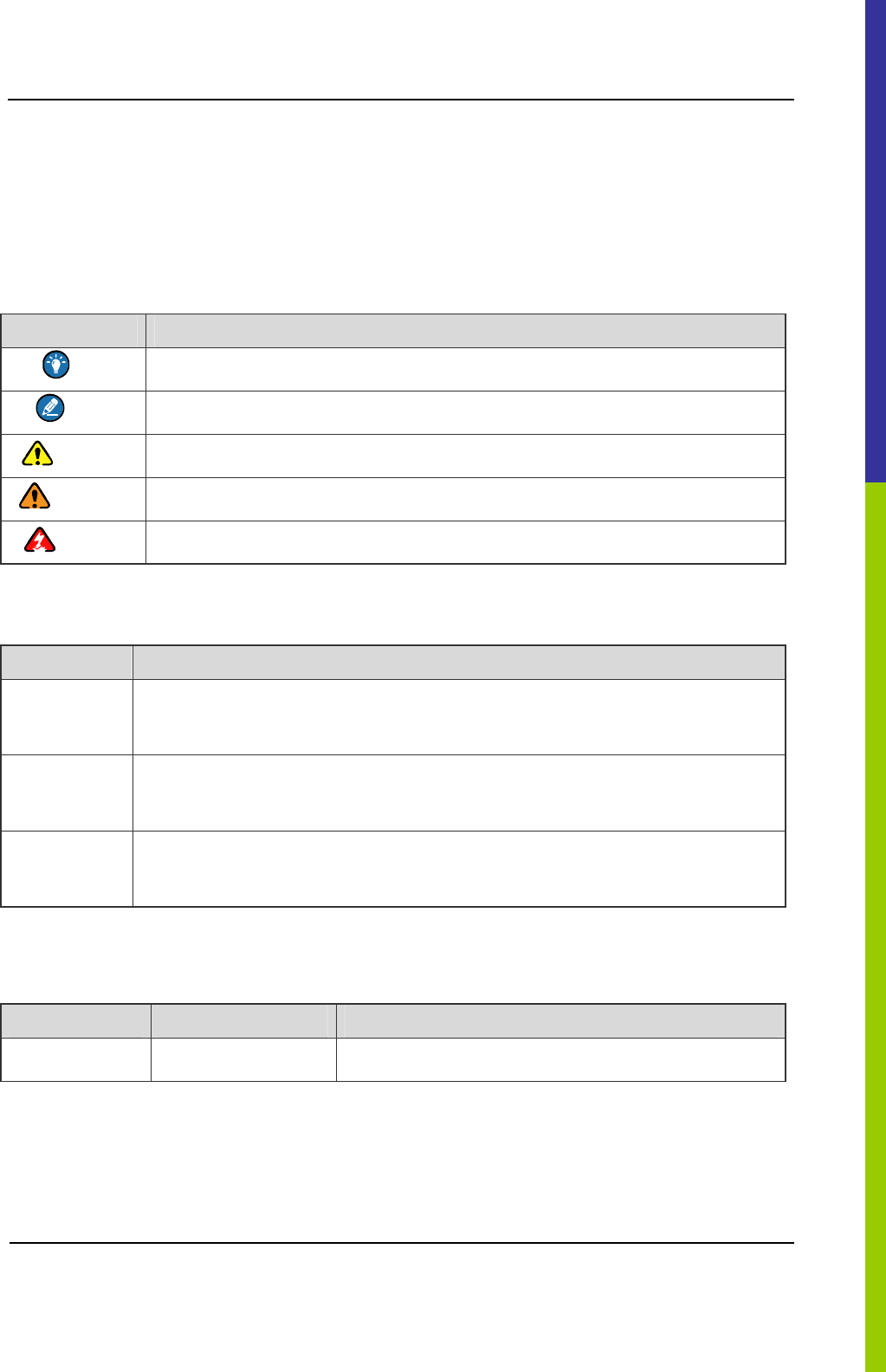
Instructional Icons
Icon Description
Tip Indicates information that can help you make better use of your product.
Note Indicates references that can further describe the related topics.
Caution Indicates situations that could cause data loss or equipment damage.
Warning Indicates situations that could cause minor personal injury.
Danger Indicates situations that could cause major personal injury or even death.
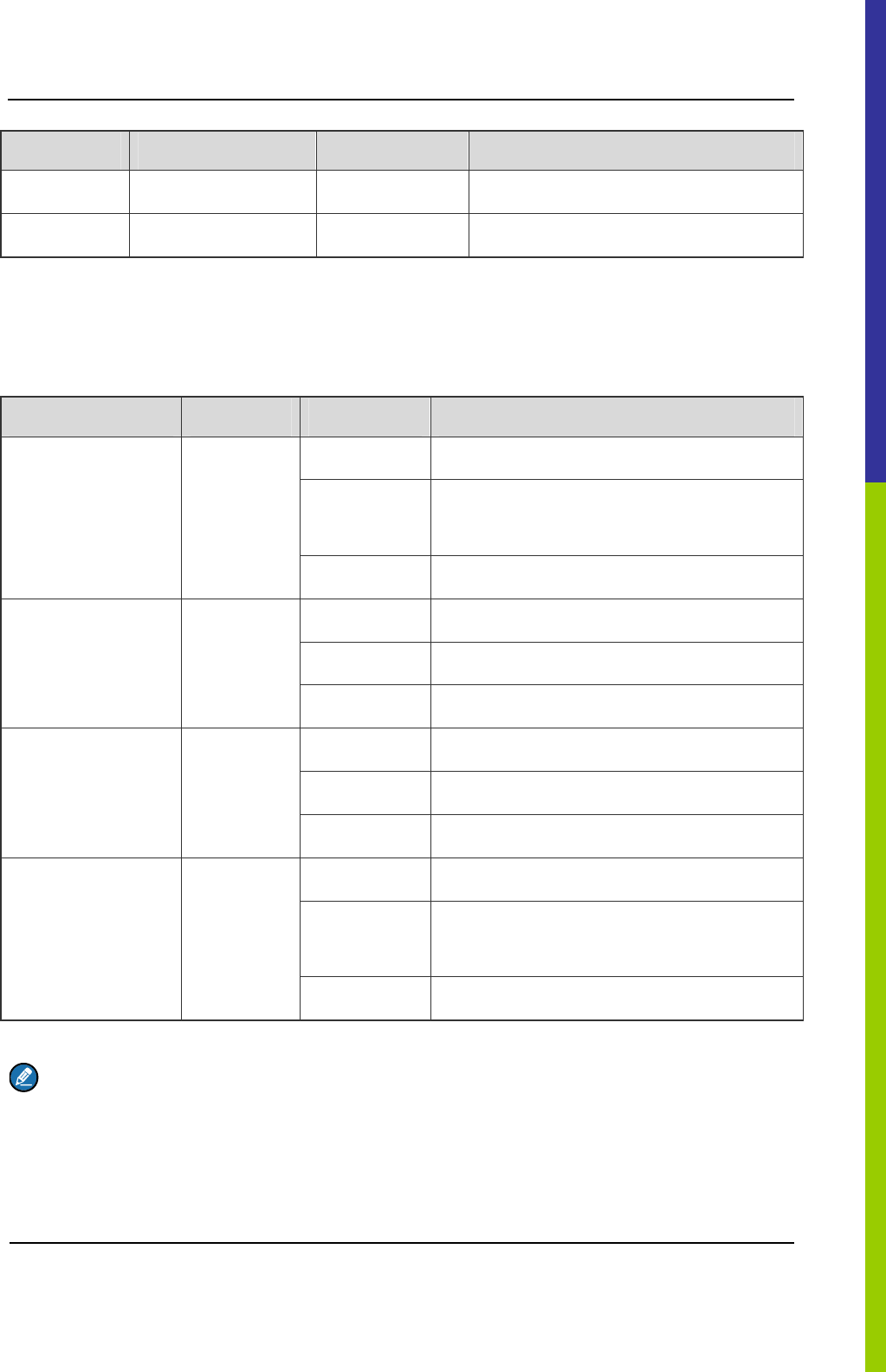
Notational Conventions
Item Description
“ ”
This symbol is used to describe name of an interface control item. For example, click
“OK”.
Ǐ ǐ This symbol is used to describe name of a button for a terminal. For example, press
the PTT key.
->
This symbol is used to direct you to access multi-level menus. For example, to select
“New” from the “File” menu, we will describe it as follows: File->New.
Revision History
Version Release Date Description
V00 July 29th, 2011 Initial Release.
Checking Items in the Package DS-6210 Base Station Owner's Manual
2
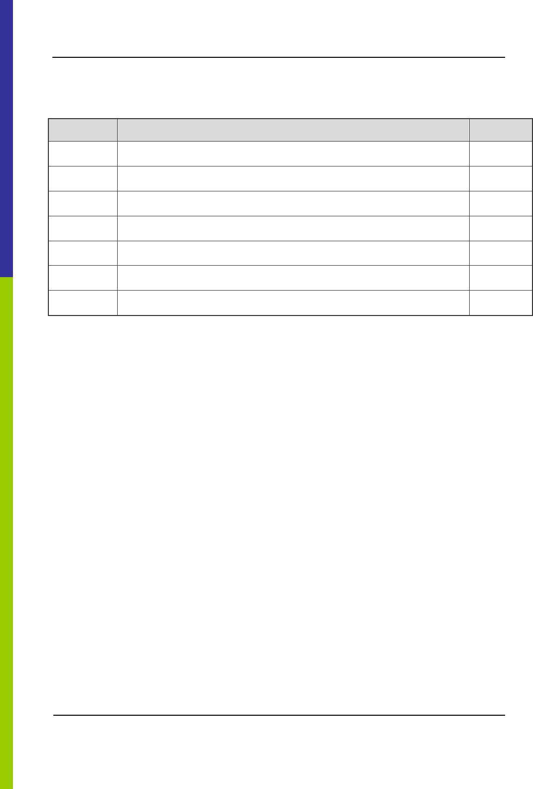
1. Checking Items in the Package
No. Item Qty. (PCS)
1 Base Station Controller Unit (BSCU) 1
2 Channel Unit (CHU) 4
3 Power Support Unit (PSU) 2
4 Fan Unit 1
5 Divider Unit (DIU) 1
6 Combiner Unit (COM) 1
7 Cabinet Kit 1
Figure 1-1 Packing List
DS-6210 Base Station Owner's Manual Product Controls
3
2. Product Controls
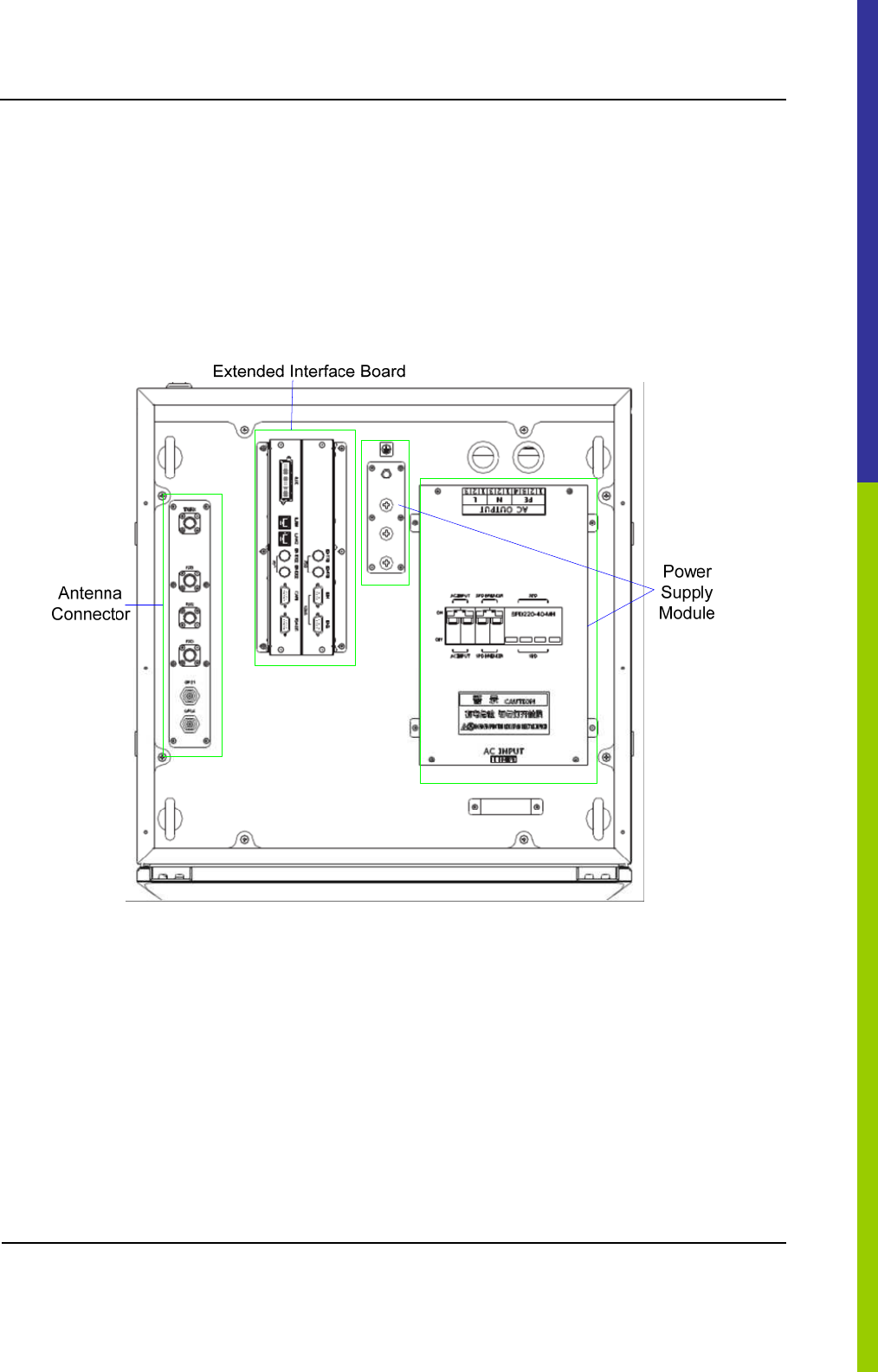
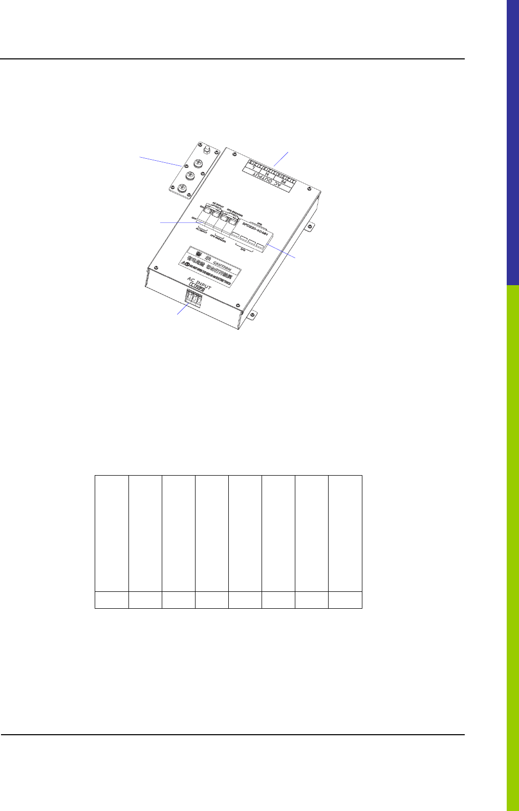
2.1 Base Station Interface Unit
The base station interface unit on top of the cabinet consists of the antenna connector, extended
interface board and power supply module. See Figure 2-1.
Figure 2-1 Components of Base Station Interface Unit
2.1.1 Antenna Connector
The antenna connector is described in Figure 2-2.
Product Controls DS-6210 Base Station Owner's Manual
4
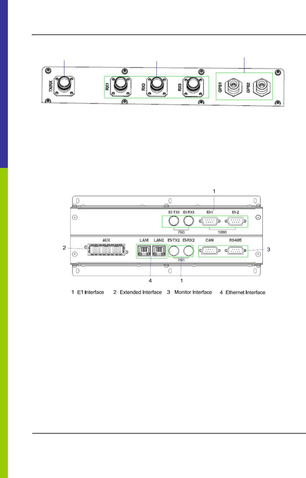
1 GPS Antenna Connector 2 RX Antenna Connector 3 TX Antenna Connector
1
23
Figure 2-2 Antenna Connector
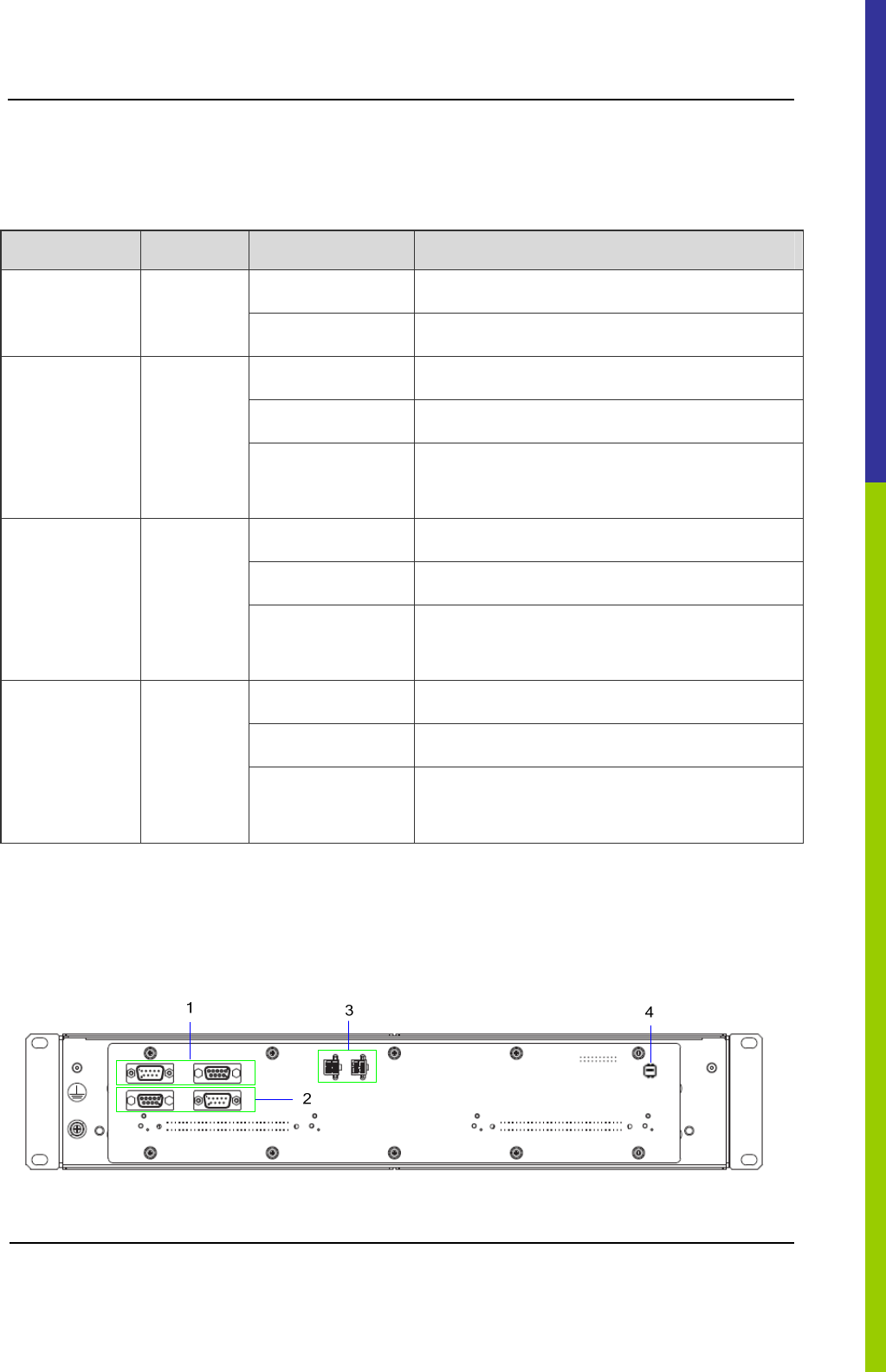
2.1.2 Extended Interface Board
The extended interface board consists of core network interface, extended interface and monitor
interface. See Figure 2-3.
Figure 2-3 Extended Interface Board
Core network interface
The core network interface contains 4-path EI interface and 2-path Ethernet interface.
Extended interface
The extended interface has 8-path extended signals. It is applied to connect to four interconnect relay
units of another cabinet, in case of combining two cabinets.
Monitor Interface
The monitor interface includes one bus port and one RS485 port.
DS-6210 Base Station Owner's Manual Product Controls
5
2.1.3 Power Supply Module
The power supply module is described below.
1
3
5
1 Ground Row 2 Circuit Breaker 3 AC Input Terminal
4 Surge Protection Device 5 AC Output Terminal
2
4
Figure 2-4 Components of Power Supply Module
2.2 Cartridge
In accordance with the IEC60297 standard, the cartridge is 19 inches in width and 7U in height. Each
cartridge can accommodate four CHUs, two BSCUs and two PSUs. See Figure 2-5.
C
H
U
02
P
S
U
08
P
S
U
07
B
S
C
U
06
C
H
U
01
B
S
C
U
05
C
H
U
04
C
H
U
03
Figure 2-5 Full Configuration for Main Chassis
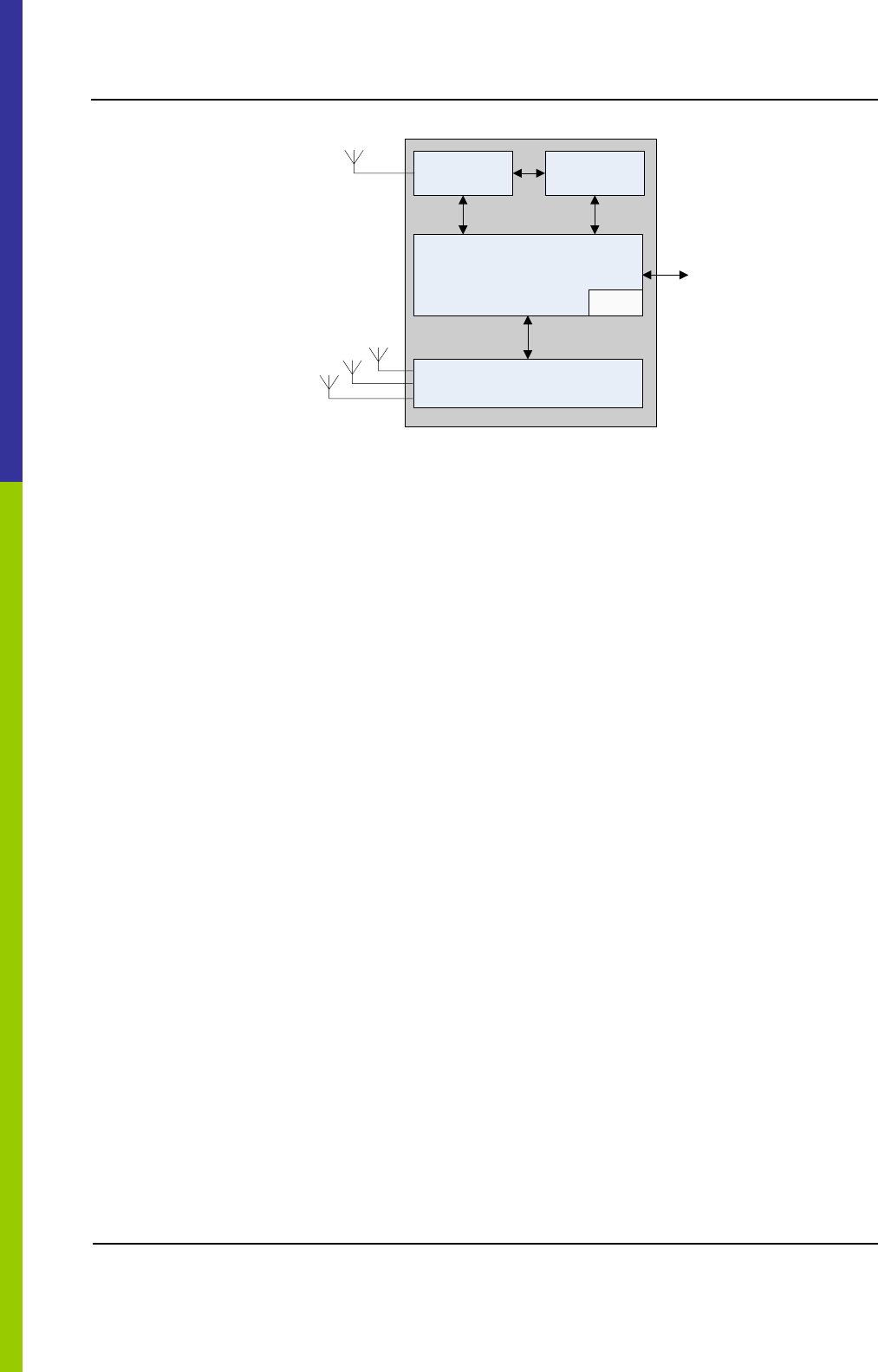
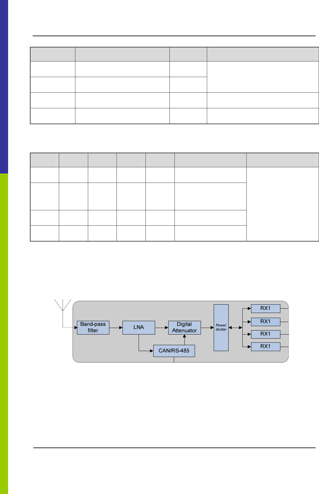
2.3 Channel Unit
The CHU logically includes power amplification, TX excitation unit, baseband signal processing unit
and diversity receiver. See Figure 2-6.
Product Controls DS-6210 Base Station Owner's Manual
6
RX Antenna 3
PA TX Excitation
Unit
Baseband Signal Processing Unit
Power
Diversity Receiver
TX Antenna
ICB
RX Antenna 2
RX Antenna 1
Figure 2-6 Logical Architecture of Channel Unit
2.3.1 Function
The CHU processes and converts protocols for the physical layer and data link layer of the PDT air
interface. Physically it consists of channel board, TX board and RX board.
z CHB: be capable of signal processing, channel encoding/decoding, interleaver and de-interleaver,
modulation/demodulation, RF signal loop-back test and fail-soft.
z TXB: be capable of modulating, upward frequency conversion, filtering and D/A conversion from
carrier baseband signal to RF signal, as well as amplifying the downlink signal.
z RXB: be capable of filtering, demodulating, downward frequency conversion, AGC and A/D
conversion from three-path carrier signal to baseband signal, as well as amplifying the uplink signal.
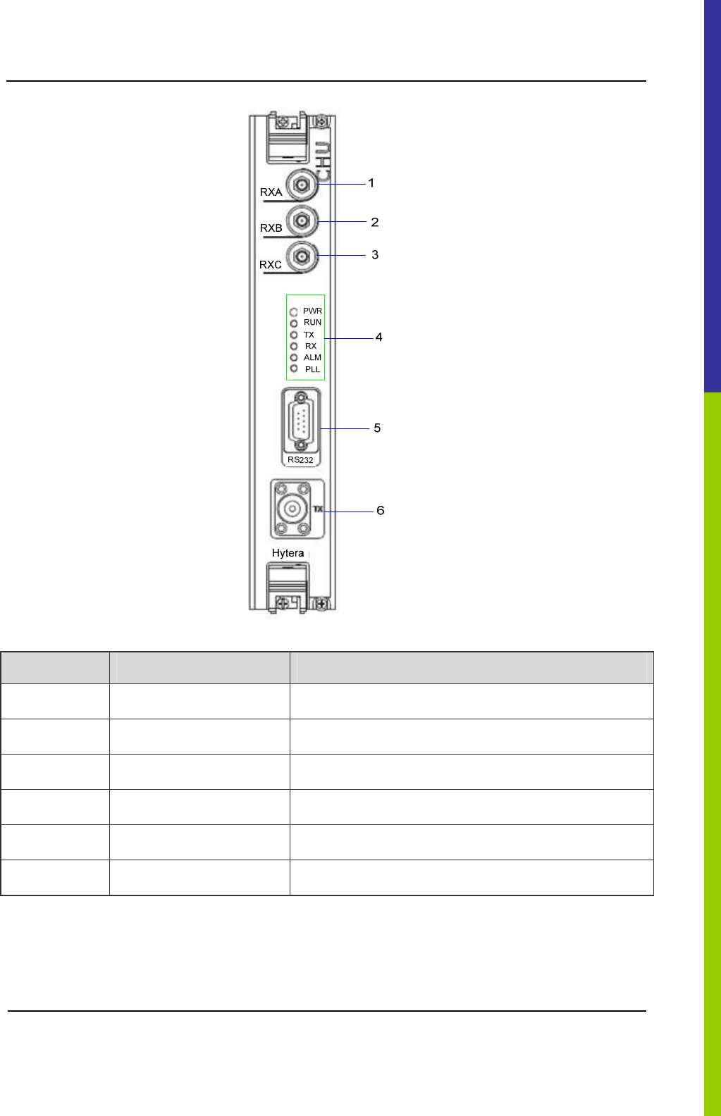
2.3.2 Front Panel
The front panel of CHU is described as follows.
DS-6210 Base Station Owner's Manual Product Controls
7
Figure 2-7 Front Panel of CHU
No. Name Description
1 RXA Diversity RX antenna input.
2 RXB RX antenna input.
3 RXC Diversity RX antenna input.
4 LED panel LED indicator
5 RS232 For commissioning.
6 TX For transmitting.
Table 2-1 Descriptions on CHU Front Panel
2.3.3 LED Indicator
The CHU indicators are described in Table 2-2.
Product Controls DS-6210 Base Station Owner's Manual
8
Name Color Status Description
On Power supply is in good working condition.
PWR Green
Off Power is failure.
On CHU is communicating with BSCU normally.
Flashing CHU is starting.
RUN Green
Off CHU is repeating.
On CHU is allocating channel.
TX Green
Off The TX channel is free.
On Carrier signal is present.
RX Green
Off The RX channel is free.
On The CHU is failure.
ALM Red
Off The CHU works properly.
On An alarm is issued due to PLL unlock.
PLL Red
Off The PLL works properly.
Table 2-2 Descriptions on CHU Indicators
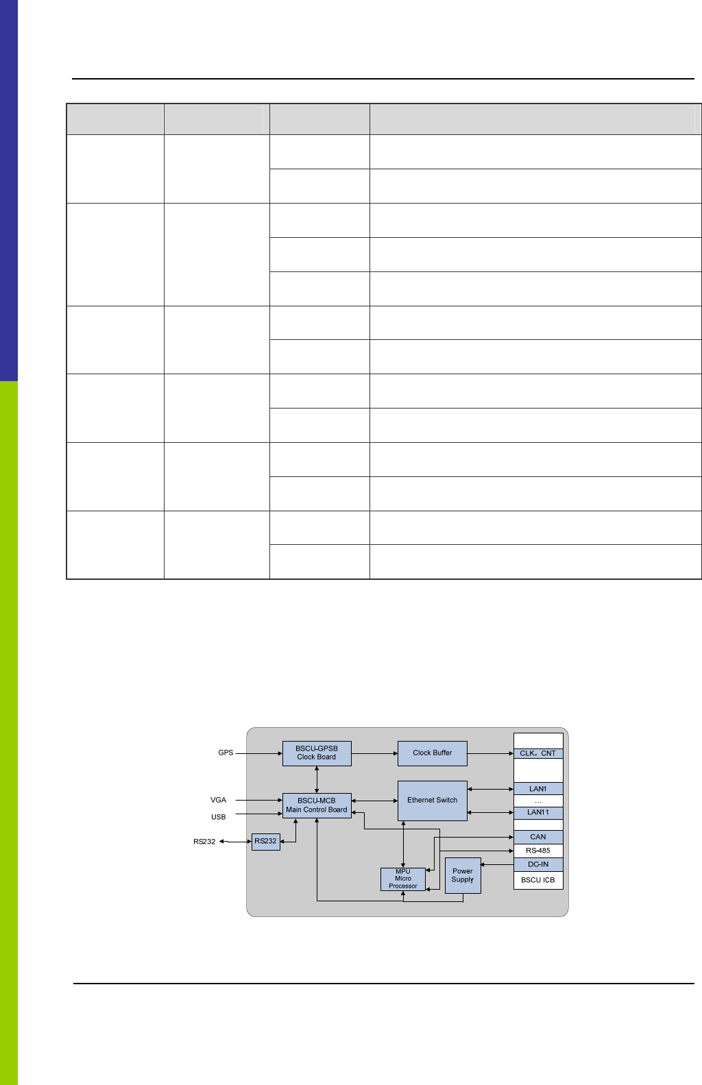
2.4 Base Station Controller Unit (BSCU)
The BSCU logically consists of clock board, main control board, clock buffer, Ethernet switch, micro
processor unit and power supply. See Figure 2-8.
Figure 2-8 Logic Architecture of BSCU
DS-6210 Base Station Owner's Manual Product Controls
9
2.4.1 Function
The BSCU is mainly in charge of managing the wireless link resources within the coverage, so as to
allocate them to different calls.
2.4.2 Front Panel
The front panel of BSCU is illustrated as follows.
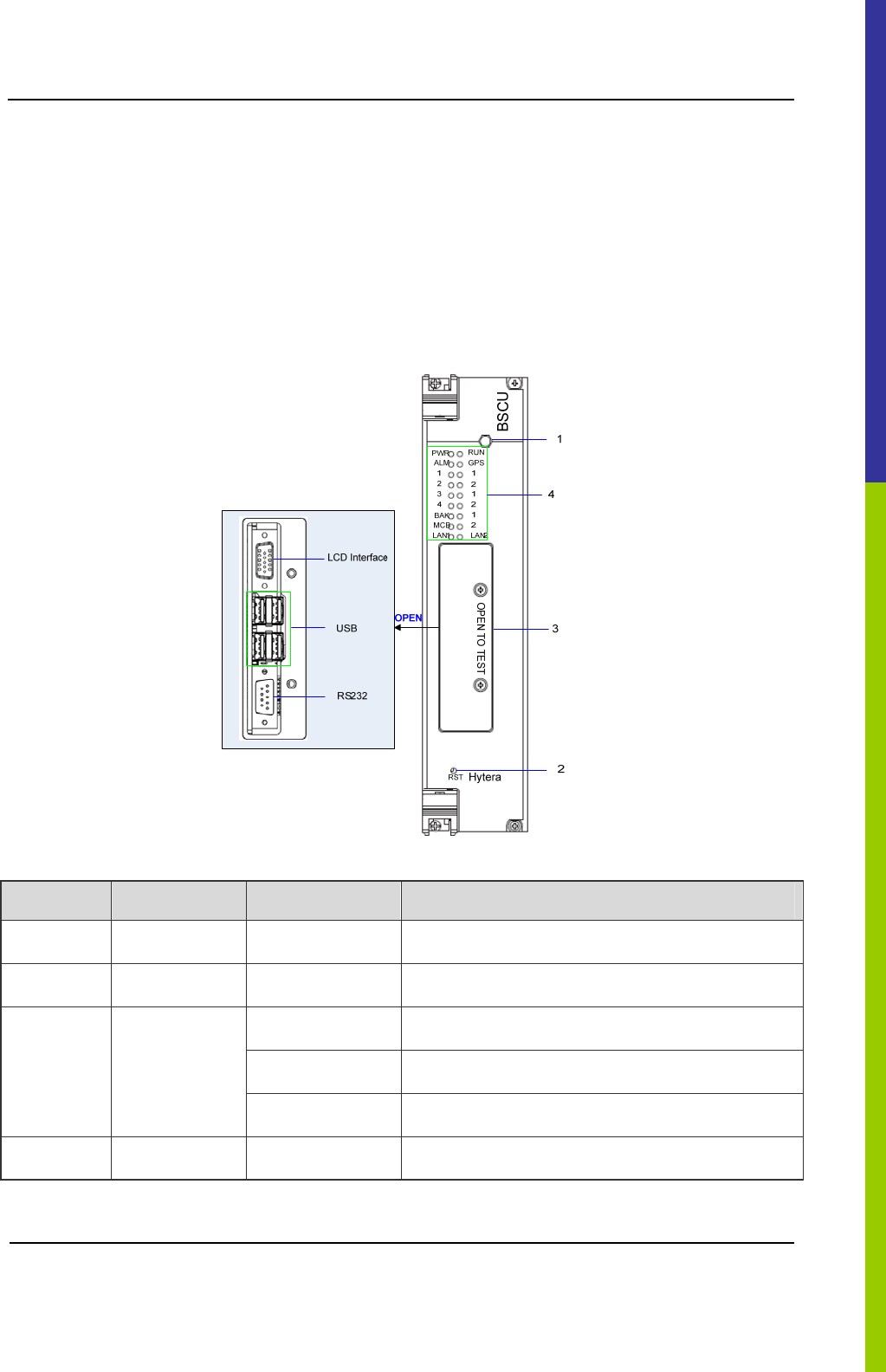
Figure 2-9 Front Panel of BSCU
No. Name Qty. Description
1 SMA Interface 1 GPS signal input.
2 RST Key 1 BSCU reset.
1 Video graphics array.
4 USB.
3
Commissioning
Interface
1 RS232.
4 LED Panel 1 LED Indicator
Table 2-3 Descriptions on BSCU Front Panel
Product Controls DS-6210 Base Station Owner's Manual
10
2.4.3 LED Indicator
The BSCU indicators are described in Table 2-4.
Name Color Status Description
On Power supply is in good working condition.
PWR Green
Off Power is failure.
Flashing
rapidly
The BSCU operates in master mode.
Flashing
slowly
BSCU operates in slave mode.
On The BSCU is starting.
RUN Green
Off The BSCU does not work properly.
Flashing Functions are disabled locally.
On Functions are disabled via GPS.
GPS Green
Off Functions are enabled via GPS.
On The BSCU is alarming.
ALM Red
Off The BSCU works properly.
On The BSCU links with the CHU properly.
Flashing
Data is being transferred or received between BSCU
and CHU.
CHU1-4 Green
Off
The link is abnormal or not connected between
BSCU and CHU.
On The BSCU links with the IRU properly.
Flashing
Data is being transferred or received between BSCU
and IRU.
IRU1-3 Green
Off
The link is abnormal or not connected between
BSCU and CHU.
DS-6210 Base Station Owner's Manual Product Controls
11
Name Color Status Description
On
The active BSCU links with the standby BSCU
properly.
Flashing
Data is being transferred or received between the
standby BSCU and active BSCU.
BAK Green
Off
The link is abnormal or not connected between the
standby BSCU and active BSCU.
On The BSCU links with the MCB properly.
Flashing
Data is being transferred or received between BSCU
and MCB.
MCB Green
Off
The link is abnormal or not connected between
BSCU and MCB.
On The BSCU links with the LNA properly.
Flashing
Data is being transferred or received between BSCU
and LAN.
LAN1-2 Green
Off
The link is abnormal or not connected between
BSCU and LAN.
Table 2-4 Descriptions on BSCU Indicators
2.4.4 Power Support Unit (PSU)
The PSU consists of power monitoring board, power module and LED panel.
2.4.5 Function
All functions of PSU are described in Table 2-5.
No. Item Description
1 External power supply input 90~264V AC 47~63Hz
2
Voltage output (for main
device)
13.5V DC
3 Voltage output (for CHU PA) HVCC˄13.5V DC˅
Product Controls DS-6210 Base Station Owner's Manual
12
No. Item Description
4
Voltage output (for other
power supply from the CHU )
LVCC˄13.5V DC˅
5 Voltage output (for BSCU) BSC_V˄13.2V DC˅
6 I/O interface
It is connected to 2 BSCUs and outputs three channel
signals. The first two is used for resetting PSU, and
the last for installation status of PSU.
7 Monitor Interface
It is connected to 2 BSCUs respectively, and outputs
two signals including RS485 and CAN-BUS.
Table 2-5 Descriptions on PSU
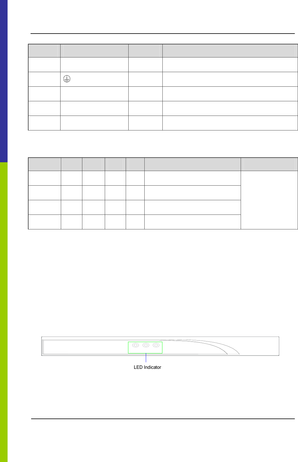
2.4.6 Front Panel
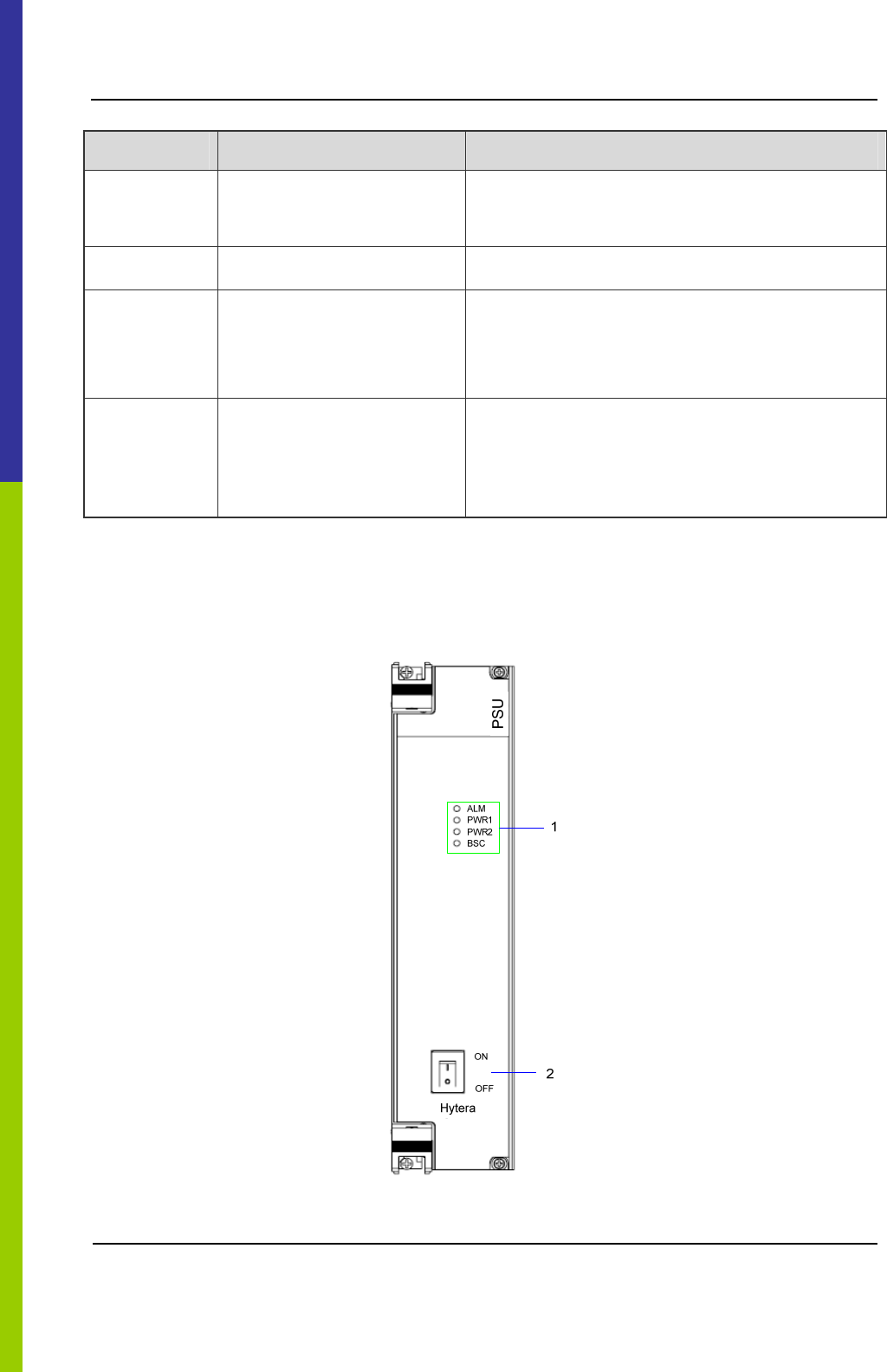
The front panel of PSU is illustrated as follows.
Figure 2-10 Front Panel of PSU
DS-6210 Base Station Owner's Manual Product Controls
13
No. Name Qty. Description
1 LED Panel 1 LED indicator
2 ON/ OFF Switch 1 Power Switch
Table 2-6 Descriptions on PSU Front Panel
2.4.7 LED Indicator
The PSU indicators are described in Table 2-7.
Name Color Status Description
On Major alarm.
Blinking per
second
Minor alarm.
ALM Red
Off The PSU works properly.
On Path 1 outputs normally.
Flashing Path 1 outputs HVCC or LVCC alarm.
PWR1 Green
Off No voltage is available in Path 1.
On Path 2 outputs normally.
Flashing Path 2 outputs HVCC or LVCC alarm.
PWR2 Green
Off No voltage is available in Path 2.
On The output voltage for BSC is normal.
Blinking per
second
An alarm is issued due to over-voltage or low
voltage for BSC.
BSC Green
Off The voltage for BSC is failure.
Table 2-7 Descriptions on PSU Indicators
Note:
The power module has two-path outputs including VCC and LVCC.
2.4.8 Interconnect Backboard (ICB)
The ICB is utilized to achieve power interconnection, synchronization clock interconnection, signaling,
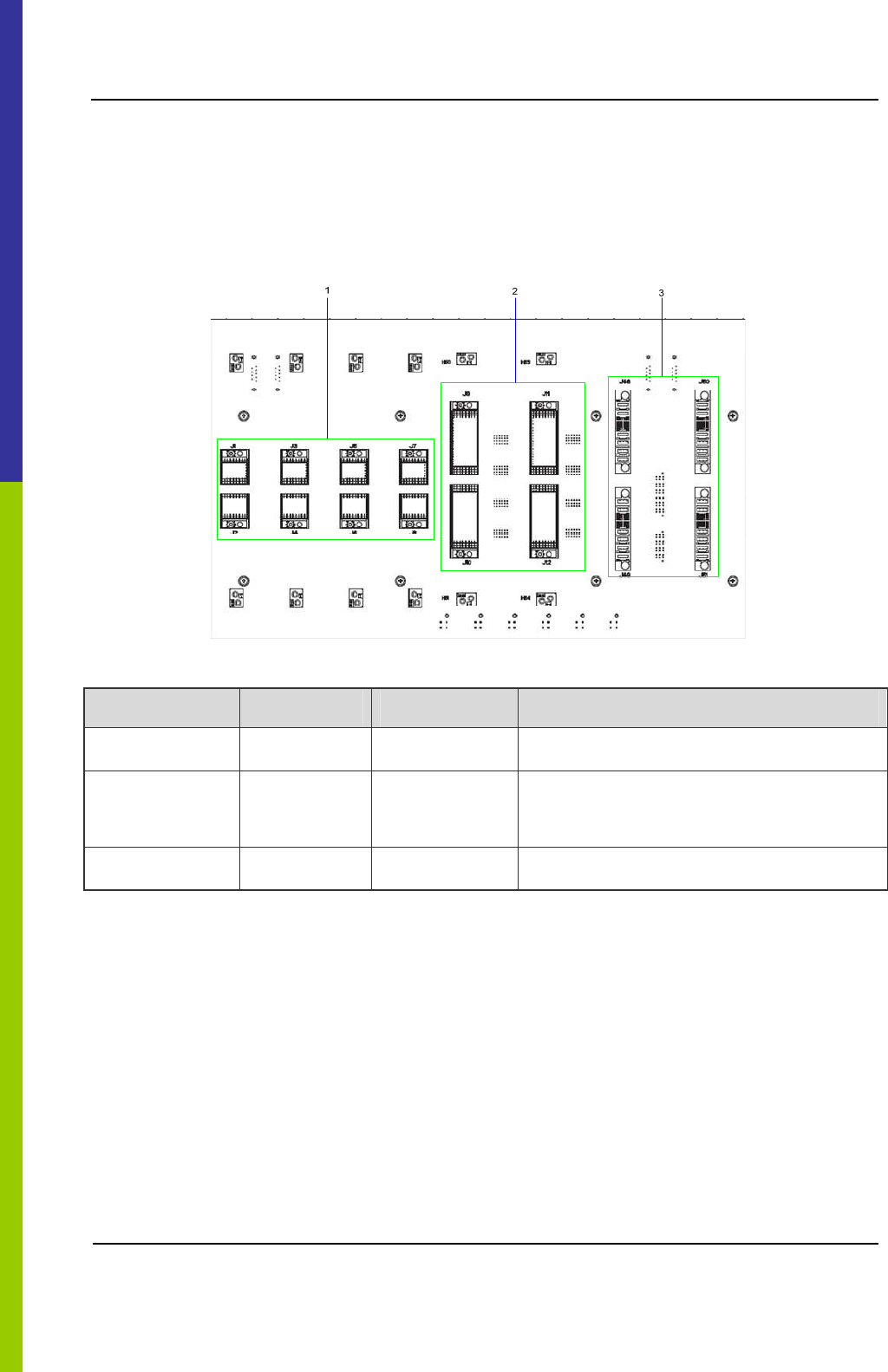
Product Controls DS-6210 Base Station Owner's Manual
14
voice and data interconnection, monitor interconnection, and I/O interconnection.
2.4.9 Front Side
The front side of ICB is described below.
Figure 2-11 ICB (front side)
No. Name Qty. Description
1 CHU Interface 4 For signal from CHU to ICB.
2
BSCU
Interface
2 For signal from BSCU to ICB.
3 PSU Interface 2 For signal from PSU to ICB.
Table 2-8 Description on ICB (front side)
2.4.10 Back Side
The back side of ICB is described below.
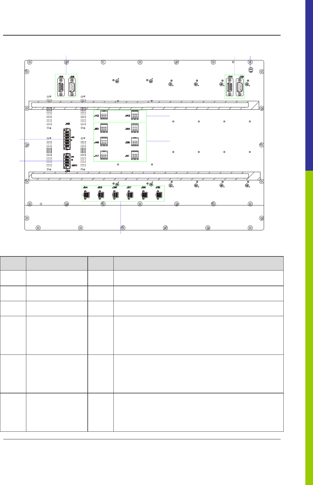
DS-6210 Base Station Owner's Manual
Product Controls
15
65
1
2
7
3
4
8
Figure 2-12 ICB (back side)
No. Name Qty. Description
1 DC Power Inlet 1 DC power input: -48V(NA now)
2 AC Power Inlet 1 AC power input: 110V/220V
3 EC Interface 2 For interconnecting two cartridges in the cabinet.
4 EIB Interface 6
For interconnecting two EC cartridges and four IRUs between
two cabinets, and also working as the signal interfac
e from
EIB to ICB in the core network interface board.
5
Monitor
Interconnection
Interface
2 For RS485 bus.
6
Monitor
Interconnection
Interface
2 For CAN-BUS.
Product Controls DS-6210 Base Station Owner's Manual
16
No. Name Qty. Description
7 Power Outlet 6 DC power (+13.2V) for BSCU, FAN and DIU.
8 DIP Switch 1 For setting the cartridge address.
Table 2-9 Description on ICB Interfaces (Back Side)
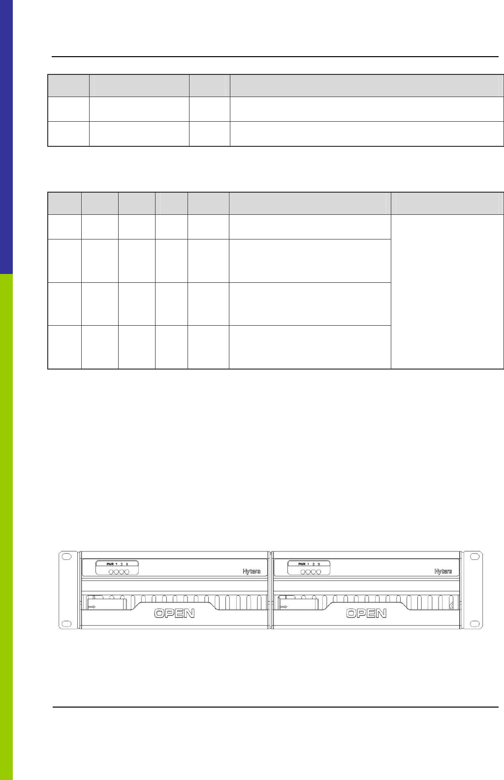
The settings of DIP switch are descried in Table 2-10.
No. 4 3 2 1 Description Remark
1 X ON X ON Address for main chassis.
2 X ON X OFF
Address for the first extended
chassis.
3 X OFF X ON
Address for the second extended
chassis.
4 X OFF X OFF
Address for the third extended
chassis.
X: reserved.
Table 2-10 Description on ICB DIP Switch
2.5 Fan Unit (FAN)
The FAN consists of a fan cartridge and two independent plugged sub-rack modules. The fan monitor
board is located on the back side of fan cartridge. It can accommodate two independent fan sub-racks
modules, each of which has three fans, four LEDs and two temperature sensors.
2.5.1 Front Panel
The front panel is illustrated in Figure 2-13.
Figure 2-13 Front Panel of FAN
DS-6210 Base Station Owner's Manual Product Controls
17
2.5.2 LED Indicator
The FAN indicators are described in Table 2-11.
Name Color Status Description
On Power supply is in good working condition.
PWR Red
Off Power is failure.
On FAN1 works properly.
Off FAN1 is out of operation or not installed.
1 Green
Blinking per
second
FAN1 does not work properly.
On FAN2 works properly.
Off FAN2 is out of operation or not installed.
2 Green
Blinking per
second
FAN2 does not work properly.
On FAN3 works properly.
Off FAN3 is out of operation or not installed.
3 Green
Blinking per
second
FAN3 does not work properly.
Table 2-11 Descriptions on FAN Indicators
2.5.3 Rear Panel
The real panel of FAN is described below.
Figure 2-14 Rear Panel of FAN
Product Controls DS-6210 Base Station Owner's Manual
18
No. Name Qty. Description
1 RS485 Monitor Interface 2
2 CAN-BUS Monitor Interface 2
For connecting ICB and DIU.
3 Power Inlet 2 For connecting ICB.
4 DIP Switch 1 For setting the fan address.
Table 2-12 Descriptions on FAN Front Panel
The settings of DIP switch are descried in Table 2-13.
No. 4 3 2 1 Description Note
1 ON ON X X The first FAN address
2 ON OFF X X
The second FAN
address
3 OFF ON X X The third FAN address
4 OFF OFF X X The fourth FAN address
X: reserved.
Table 2-13 Descriptions on FAN DIP Switch Settings
2.6 Divider Unit (DIU)
The logic diagram of DIU is described in Figure 2-15.
Figure 2-15 Diagram of DIU
2.6.1 Function
The DIU is in charge of allocating the received signal to each transceiver.

DS-6210 Base Station Owner's Manual Product Controls
19
2.6.2 Front Panel
The front panel of DIU is illustrated as follows.
Figure 2-16 Front Panel of DIU
No. Name Qty. Description
1 RXA 8 Diversity RX antenna output.
2 RXB 8 RX antenna output.
3 RXC 8 Diversity RX antenna output.
Table 2-14 Descriptions on DIU Front Panel
2.6.3 Rear Panel
The real panel of DIU is described below.
Figure 2-17 Rear Panel of DIU
No. Name Qty. Description
1 SWITCH 1 For setting the DIU address
2 RS485 2 Monitor Interface
3 CAN-BUS 2 Monitor Interface
Product Controls DS-6210 Base Station Owner's Manual
20
No. Name Qty. Description
4 PWR 1 Power Inlet
5 1 For grounding
6 RXA 1 Diversity RX antenna A
7 RXB 1 Diversity RX antenna B
8 RXC 1 Diversity RX antenna C
Table 2-15 Descriptions on DIU Rear Panel
The setting of DIU address is specified in Table 2-16.
No. 1 2 3 4 Description Note
1 ON ON X X The first DIU address
2 ON OFF X X The second DIU address
3 OFF ON X X The third DIU address
4 OFF OFF X X The fourth DIU address
X: reserved.
Table 2-16 Description on DIU Address Setting
2.7 Router
2.7.1 Function
The router is used for selecting the routing device for message flow or data grouping.
2.7.2 Front Panel
The front panel of router is described in Figure 2-18.
PWR SYS ESM
Figure 2-18 Front Panel of Router
DS-6210 Base Station Owner's Manual Product Controls
21
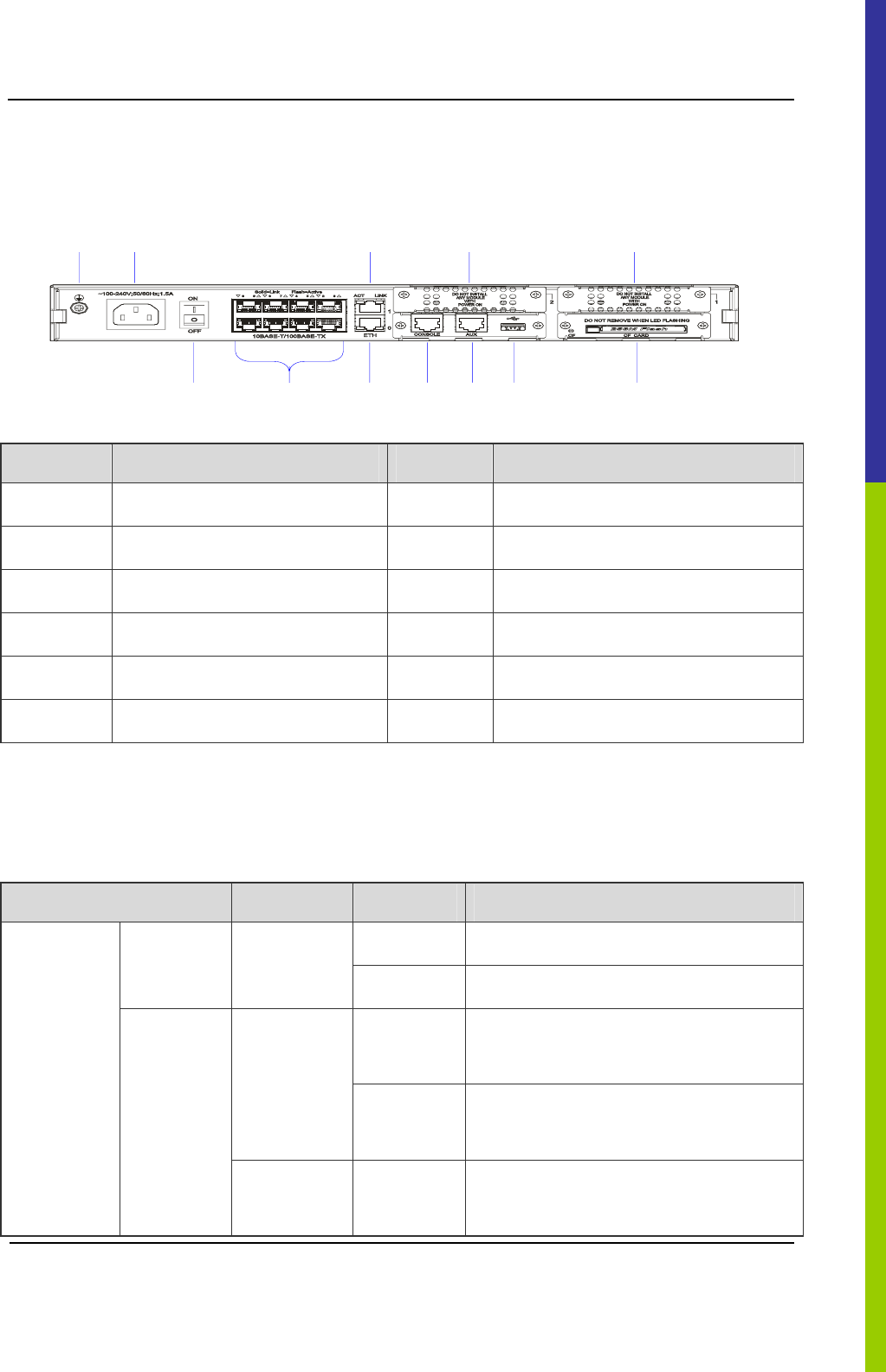
2.7.3 Rear Panel
The real panel of router is described as follows.
347 1 2
512 6 8 9 10 11
Figure 2-19 Rear Panel of Router
No. Name No. Name
1 SIC Slot 2 2 SIC Slot 1
3 Ground Port 4 Power Inlet
5 Power Switch 6 Ethernet Port (LAN0)
7 Ethernet Port (LAN1) 8 Configuration Port (CON)
9 Auxiliary Port (AUX) 10 USB Port
11 CF Card 12 L2 Switch Port (LAN2-LAN9)
Table 2-17 Descriptions on Router Rear Panel
2.7.4 LED Indicator
The router indicators are described in Table 2-18.
Name Color Status Description
On Power supply is in good working condition.
PWR -
Off Power is failure.
Flashing
rapidly
The system is starting.
Green
Flashing
slowly
The system works properly.
Front Panel
SYS
Yellow
Flashing
rapidly
The system is failure.

Product Controls DS-6210 Base Station Owner's Manual
22
Name Color Status Description
- Off The system does not work properly.
On The ESM card works properly.
Green Flash
Slowly
The router is starting.
Yellow On The ESM card is failure.
ESM
- Off The ESM card is not inserted.
On The link is not connected.
LINK -
Off The link has been connected.
Flashing Data is being transferred or received.
ACT -
Off No data is being transferred or received.
On The CF card has been inserted.
Green
Flashing The CF card is reading or writing.
Yellow On The CF card is failure.
Rear Panel
CF
- Off The CF card is not inserted or identified.
Table 2-18 Descriptions on Router Indicators
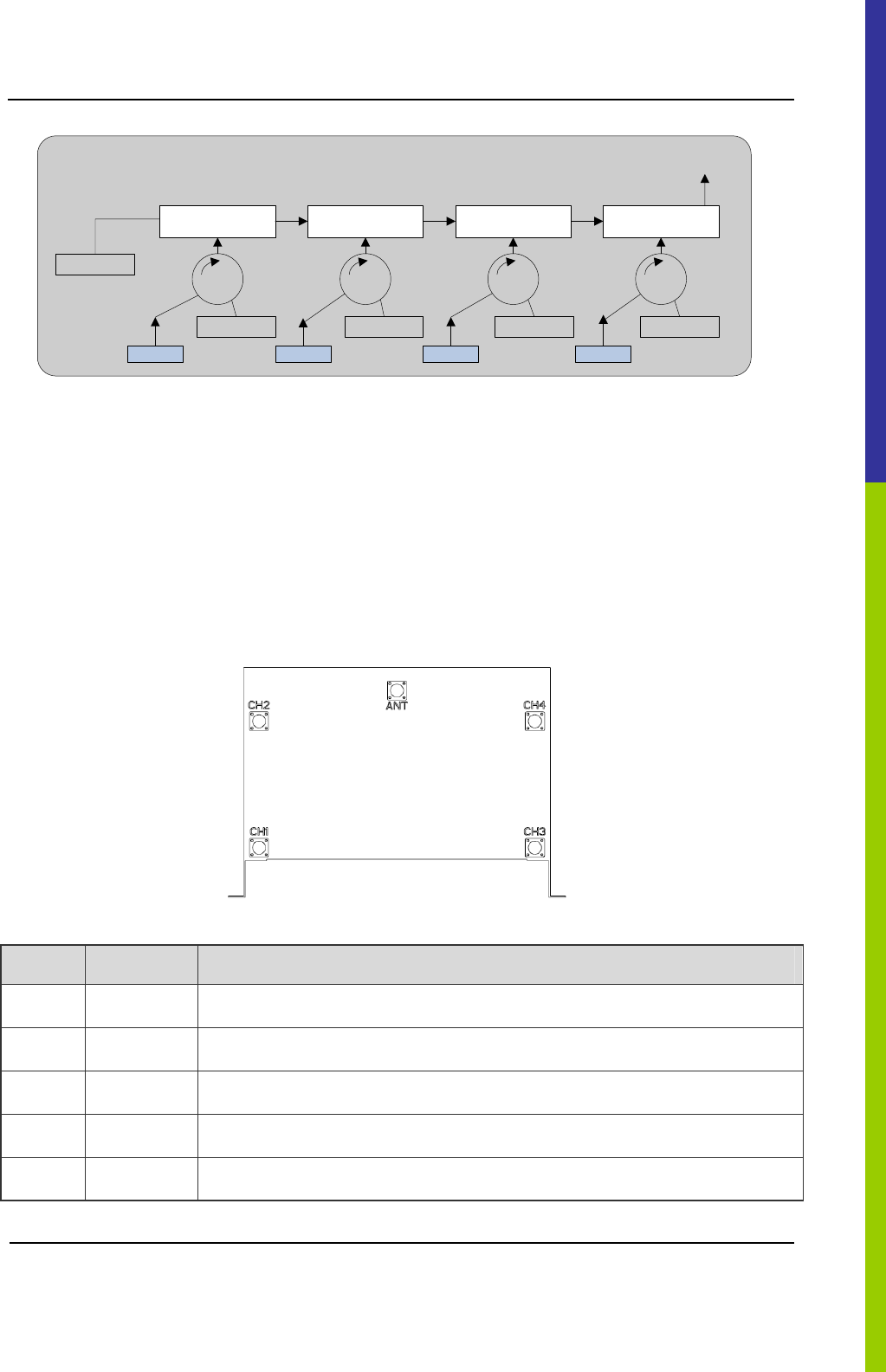
2.8 Combiner (COM)
The COM is classified into broadband hybrid combiner, manual tune cavity combiner, and auto tune
cavity combiner. The broadband hybrid combiner is applied to the base station with two-carrier, while
the manual tune cavity combiner to the base station with more than two-carrier. The logic diagram of
four combiners is shown in Figure 2-20.
DS-6210 Base Station Owner's Manual Product Controls
23
Cavity Resonator Cavity Resonator Cavity Resonator Cavity Resonator
50
50505050
CHU1 CHU2 CHU3 CHU4
COM Output
Figure 2-20 Logic Diagram of Four Combiners
2.8.1 Function
The COM is used to integrate multiple carriers from the base station sub-system into one output port to
transmit by an antenna.
2.8.2 Rear Panel
The rear panel of combiner is described below.
Figure 2-21 Rear Panel of Combiner
No. Name Description
1 ANT For combing output
2 CH1 For carrier input 1
3 CH2 For carrier input 2
4 CH3 For carrier input 3
5 CH4 For carrier input 4
Table 2-19 Descriptions on COM Front Panel
Installation DS-6210 Base Station Owner's Manual
24
3. Installation
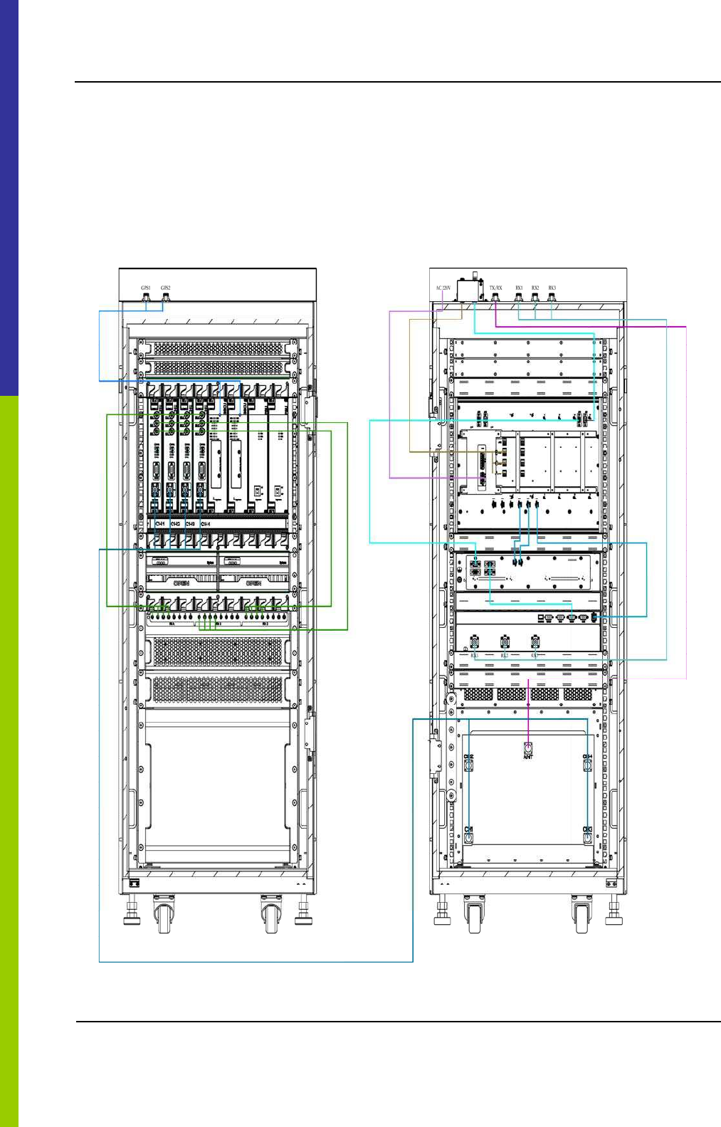
3.1 Cable Layout
The cable layout of base station is shown Figure 3-1.
Figure 3-1 Cable Layout

DS-6210 Base Station Owner's Manual Installation
25
3.2 Safety Information
To reduce the chance of accident, please read the safety precautions very carefully before installation,
maintenance and operations.
3.2.1 Power Supply
Danger:
Some components of the power system carry hazardous voltage in operation. Direct contact or indirect
contact through moist objects with these components will result in fatal injury.
z Never wear conductive objects such as watches, bracelets, rings and etc during operation.
z Do use special tools in high voltage and AC operation.
z Do keep moisture out of the power system during operation in moist environment.
z The equipment should be well earthed in time to avoid damage by lightning strikes in thunderstorm.
z Do turn off the power before assembly or disassembly
z Do verify the compliance of the cable and cable label prior to connection.
z Ensure that the equipment is well earthed before powering on.
z Turn off the power immediately when water or moisture is found on the cabinet,
z Make sure all switches of power distribution box are set to off before installation each module in the
cabinet
3.2.2 Working at Heights
Warning:
Cautions shall be taken to prevent objects from falling during working at heights.
z Safety protection measures (e.g. wearing a hamlet or the safety belt) shall be taken.
z The heat-retaining clothes shall be worn before operation in cold areas.
z Make sure that the ladder is safe for use. Overweight on the ladder is strictly prohibited.
z Protective measures shall be taken if the slant of the ladder is more than 5m or the ladder is placed
on a high ground (>3m)
z Handle and use all equipment and tools with care to avoid falling.
Installation DS-6210 Base Station Owner's Manual
26
3.3 Installation Preparation
3.3.1 Technical Files
The following table lists the files associated with hardware installation.
File type File Name Description
Network Planning Drawing
Provided by the R&D engineers or technical
sales.
Instructional
file for
installation Site Survey Report
It is filled by the investigation engineer on
site.
DS-6210 PDT Trunking System
DS-6210 PDT Trunking Base Station
Hardware Description Manual
Manuals
DS-6210 PDT Trunking Base Station
Service Manual
Shipped with the equipment
Other files Packing List Shipped with the equipment
Table 3-1 Technical Files
3.3.2 Personnel
Only the adequately trained personnel with satisfactory knowledge of the system can carry out the
installation and tuning. The number of installation persons is subject to engineering progress and
environment.
3.3.3 Tools
The following tools and meter are required before installation.
General
Tools
Claw hammer, slot type screwdriver, large Phillips screwdriver, wrench, paper knife,
connector board and A type ladder.
Special
Tools
ESD-preventive wrist strap, cable peeler and crimping pliers.
Meter Multimeter
Table 3-2 Tools and Meter
DS-6210 Base Station Owner's Manual Installation
27
3.4 Unpacking Inspection
3.4.1 Check before Unpacking
After the equipment arrives at the installation site, you should:
z Check against the packing list, including total amount, customer address, and etc.
z Contact us in case of any mistake.
z Check the packaging case is in good condition and not placed upside down.
If the outer package is damaged seriously or soaked, please contact us immediately.
Note:
To protect the equipment and investigate the cause, please properly keep the package box, equipment and
packing materials, and take photo.
If the above check results are good, unpack and check the equipment.
3.4.2 Unpacking Wooden Case
Caution:
zKeep the wooden case far away from intense shock during transportation.
zNever touch the parts with dirty glove during transportation.
If space permitting, carry the wooden case into or near the computer room before unpacking. This can
prevent the chassis from being damaged.
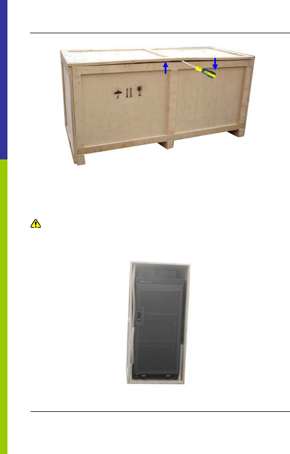
To unpack the wooden case, do as follows:
Step 1 Wear the ESD-preventive glove.
Step 2 Lay the wooden case horizontally on the ground. Do keep the side with frame down.
Insert one end of the slot type screwdriver into the seam between the cover and the case body by the
claw hammer; then remove all nails, as shown in Figure 3-2.
Tools Claw hammer and slot type screwdriver
Installation DS-6210 Base Station Owner's Manual
28
Figure 3-2 Removing the Cover
Step 3 Remove the cover. The wooden case may contain the carton or cabinet. As for the former,
directly take out the carton from the wooden case and unpack as instructed in Step 6. As for the
latter, proceed to the next steps.
Caution:
Pay attention to the nails on the cover, to avoid hand injuries.
Step 4 Place the wooden case in an upright position. Do keep the side of the cabinet with wheel down
Figure 3-3 Erecting the Wooden Case

DS-6210 Base Station Owner's Manual Installation
29
Step 5 Remove the foam plate.
Step 6 Slide the cabinet out of the wooden case slowly.
3.4.3 Unpacking Cartons
Tool Paper knife
To open a carton, do as follows:
Step 1 Check the type and quantity of articles inside the carton according to labels, and cut the straps
along the seam of the carton cover by the paper knife.
Caution:
Use moderate force to avoid damaging the articles inside.
Step 2 Remove the foam plates and articles.
3.4.4 Inspections
After unpacking all wooden cases and cartons, carefully check the name, type, quantity of goods
against the Packing List, and then accept them.
3.5 Installing the Cabinet
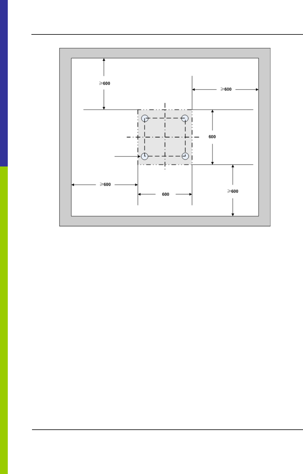
3.5.1 Determine the Installation Position
Determine the installation position of the cabinet according to the installation chart. The available
space for maintenance should be preserved and be no less than 600mm around the front and back
door, as shown in Figure 3-4 and Figure 3-5.
Installation DS-6210 Base Station Owner's Manual
30
Figure 3-4 Layout of holes for a Single Cabinet
Wheel
DS-6210 Base Station Owner's Manual Installation
31
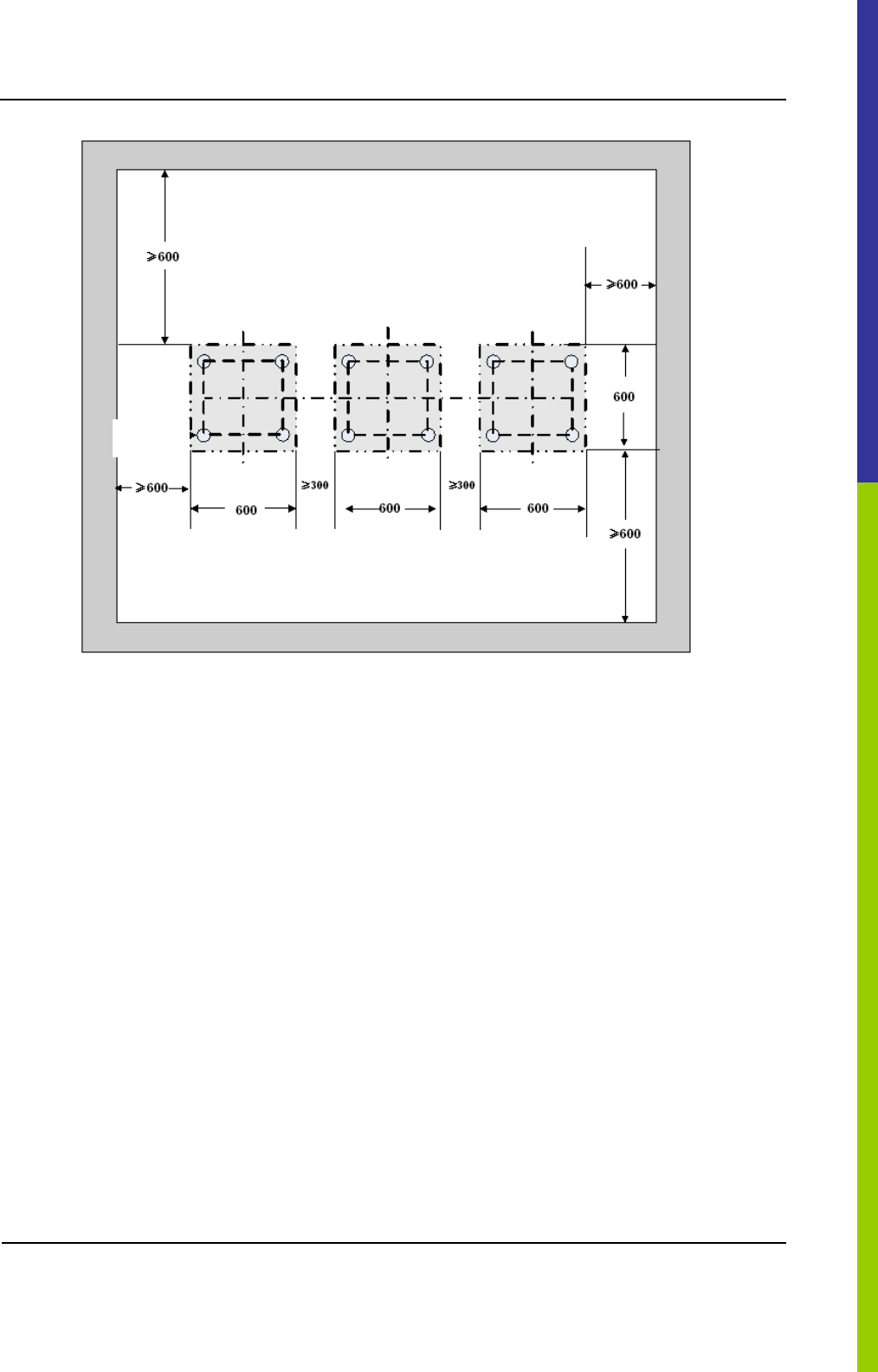
Figure 3-5 Layout of holes for Combined Cabinet
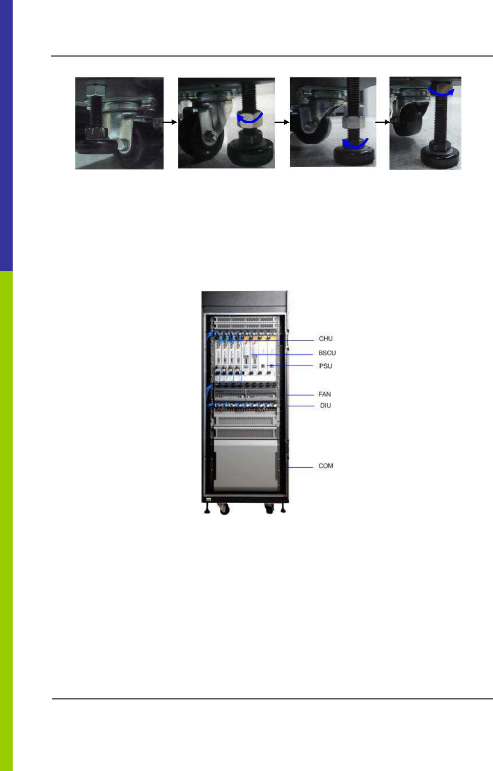
3.5.2 Installing the Cabinet
To install the cabinet, do as follows:
Step 1 Place the cabinet in the planned position.
Fix the cabinet by tightening four bolts at the bottom of the cabinet, as shown in Figure 3-6.
1. Loosen the upper nut counter-clockwise by the spanner.
2. Loosen the lower nut counter-clockwise by the spanner and lift the cabinet to an appropriate
height.
3. Tighten the upper nut and screw clockwise.
Wheel
Installation DS-6210 Base Station Owner's Manual
32
Figure 3-6 Tightening the Bolt
3.6 Installing Modules into the Cabinet
3.6.1 Module Layout
The position of all modules to be installed is shown in Figure 3-7.
Figure 3-7 of Module Layout
3.6.2 Installation Procedures
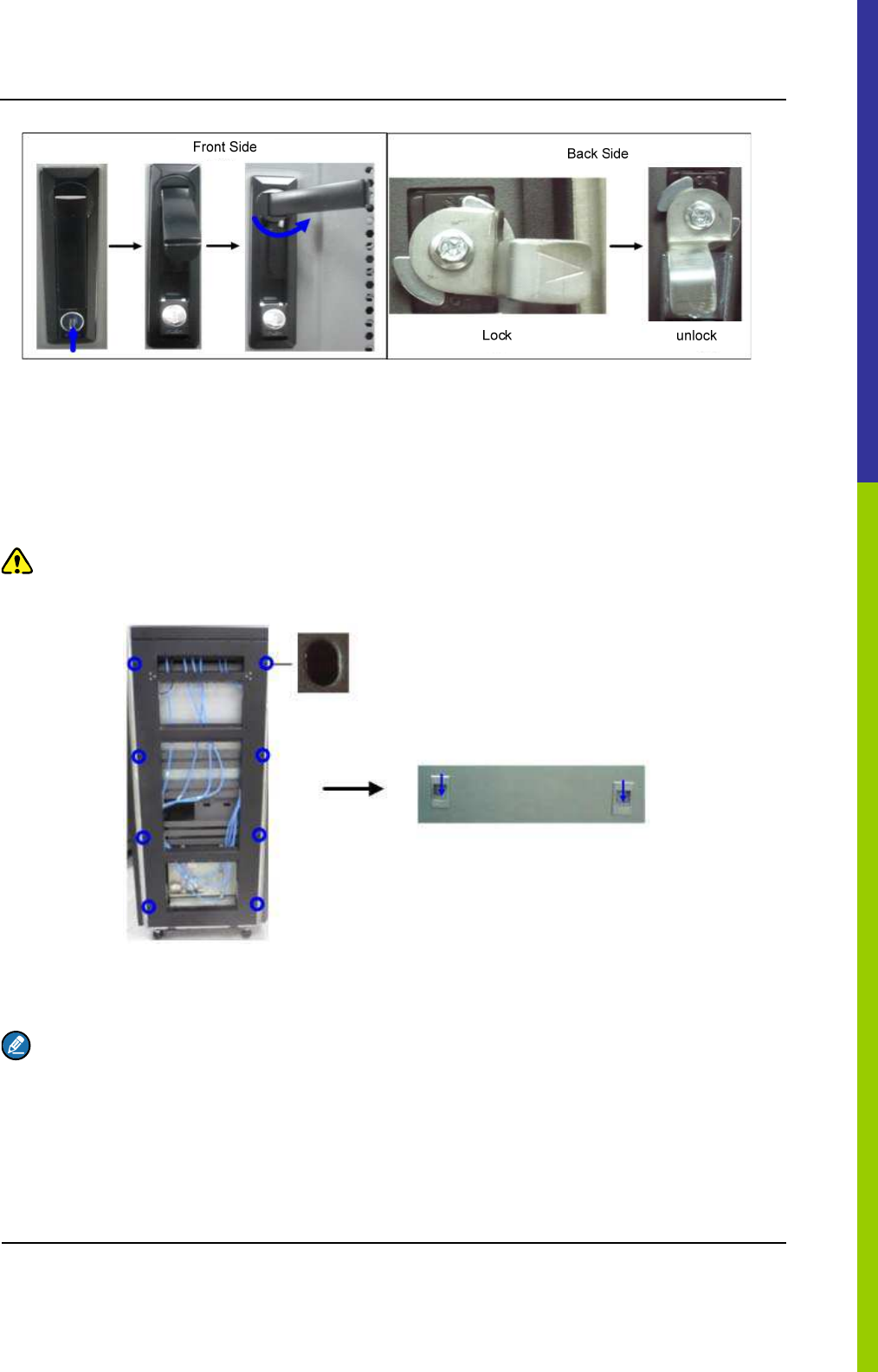
Step 1 Open the front and back door, as shown in Figure 3-8.
1. Unlock and remove the key in case of the keyhole in a vertical position.
2. Firmly press PUSH until the door knob is bounced.
3. Turn the door knob to the right.
4. Pull the door knob outwards and open the cabinet door.
DS-6210 Base Station Owner's Manual Installation
33
Figure 3-8 Opening the Cabinet Door
Step 2 Disassemble the side doors as shown in Figure 3-9.
1. Remove the eight screws on the frame.
2. Press down on the two latches and pull out the side door outwards.
Caution:
Care shall be taken to avoid injuries upon pulling out the side door outwards.
Figure 3-9 Disassembling the Side Door
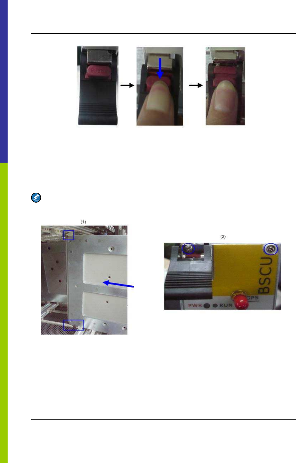
Step 3 Insert the modules into the cartridge (take the BSCU installation for example)
Note:
Make sure the power switch is set to OFF before installing the PSU.
1. Loosen the two ejectors as shown in Figure 3-10.
Installation DS-6210 Base Station Owner's Manual
34
Figure 3-10 Loosening the Ejector
2. Slide the BSCU along the guide rails smoothly as shown in Figure 3-11˄1˅.
3. Perform the step 1 in a reverse way to lock the two ejectors.
4. Tighten the two screws on the two ejectors and the board respectively as shown in Figure 3-11
˄2˅.
Note:
Loosen the two ejectors and draw out the module in case of removing it during installation.
Push
Figure 3-11Installing the BSCU
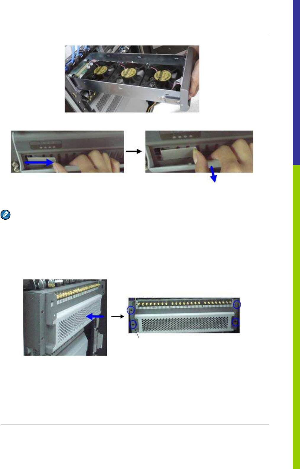
Step 4 Install the FAN as shown in Figure 3-12.
Slide the FAN along the guide rails smoothly until a click is heard.
DS-6210 Base Station Owner's Manual Installation
35
Figure 3-12 Installing the FAN
Figure 3-13 Removing the FAN
Note:
Pull the latch inwards and pull out the FAN in case of removing it during installation. See Figure 3-13.
Step 5 Install the DIU as shown in Figure 3-14.
1. Slide the DIU along the guide rails.
2. Fasten all screws to fix the DIU.
Fasten the Screw
Figure 3-14 Installing the Divider Unit
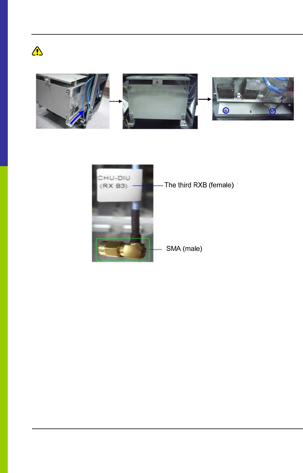
Step 6 Install the COM as shown in Figure 3-15.
1. Slide the COM along the guide rails.
2. Fasten the four screws.
Installation DS-6210 Base Station Owner's Manual
36
Caution:
Handle with care as the COM is heavy.
Figure 3-15 Installing the Combiner Unit
Step 7 Connect all cables as shown in Figure 3-16.
Figure 3-16 Cable Diagram
Step 8 Install the side doors.
1. Align the side door with the frame and firmly press the latch.
2. Fasten the eight screws.
3.7 Installing Cables
3.7.1 Equipment Status
The equipment shall be in the following status before connecting cables:
z The cabinet has been installed.
z All modules have been installed and the power switch is set to OFF.
DS-6210 Base Station Owner's Manual Installation
37
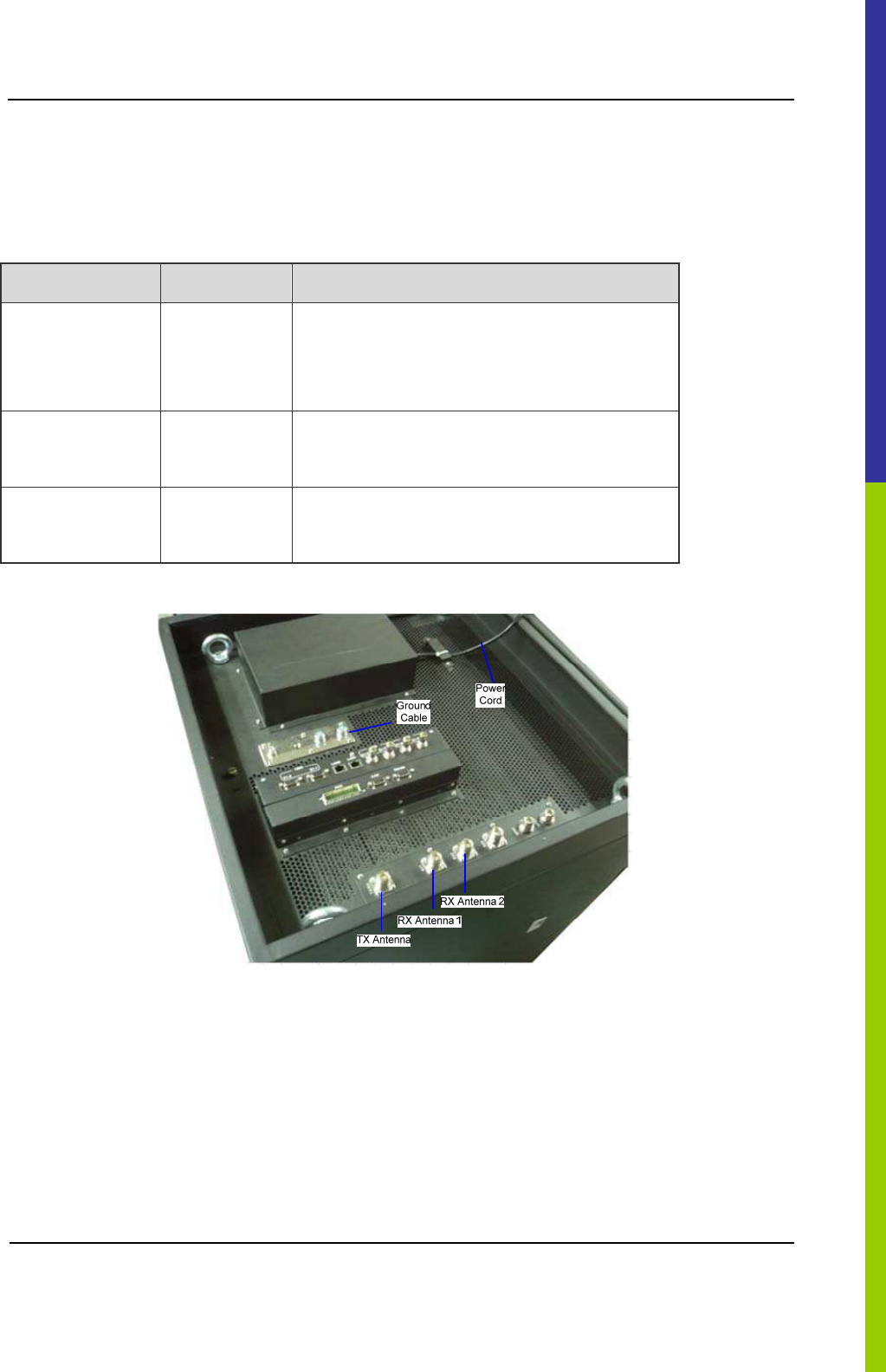
3.7.2 Cables
Cables are described in Table 3-3 and their positions are shown in Figure 3-17. Installation positions
are located on top of the cabinet.
Name Color Remark
Base Station
Ground Cable
(40m)
Yellowish
green
16 mm2, 49-core, and 450/750V
Subject to the actual needs.
AC Power Cord
(15m)
Black Subject to the actual needs
RF Jumpers (3
pcs)
Black 1/2 inch, N-Male to N-Male
Table 3-3 Cables Description
Figure 3-17 External Cable Connection
3.8 Examination after Installation
3.8.1 Equipment Status
The equipment shall be in the following status prior to hardware examination.
z The cabinet has been installed.
Installation DS-6210 Base Station Owner's Manual
38
z All modules have been installed.
z The external power has been installed and all cables have been connected.
z All switches of the power distribution box are set to OFF.
3.8.2 Examining the Cabinet
The following requirements shall be met after installation.
No. Check Item
1 The position of the cabinet should conform to the design drawing.
2 All modules should be installed correctly.
3 All cables within the cabinet should be connected properly.
4 The side door should be installed and the grounding cables should be connected properly.
5
All screws should be tightened. Be sure to put flat washers and spring washers on all bolts
correctly.
6 The cabinet should be placed horizontally and orderly.
7
The surface of the cabinet should be clean and well painted. No dust and other sundries are in
the cabinet.
8 All labels should be correct, clear and not be missed.
9 The plastic dust cap on top of the cabinet should be installed properly.
Table 3-4 Checklist of Cabinet Installation
3.8.3 Examining Cables
The following requirements should be met after connection.
No. Check Item
1 All cables should not be damaged.
2 All cables are one-piece cables, without any joint in the middle.
3 Excess grounding cables should be cut off.
Table 3-5 Checklist of Cables
DS-6210 Base Station Owner's Manual Installation
39
3.8.4 Power On and Examination
Caution:
First measure the resistance of all power connectors and ground connectors using the multimeter and check
whether short circuit occurs.
The procedures are described as follows:
Step 1 Check the input voltage (220V) from the main power and whether the live line and null line
connect correctly.
Step 2 All switches of PSU are set to ON.
Step 3 Check whether all modules are powered properly.
Name Normal Power Indication
CHU The PWR indicator on the front panel glows and the ALM indicator goes out.
BSCU The PWR indicator on the front panel glows and the ALM indicator goes out.
PSU The PWR indicator on the front panel glows and the ALM indicator goes out.
FAN The PWR indicator on the front panel glows.
Table 3-6 Checklist of Power Situation
Note:
If the LED on the front panel does not work correctly, please re-power it on or re-insert the module after
disconnecting power. If it doesn’t solve the problem, please contact us.
3.8.5 Environment Examination
The following table lists the check item of environment on site.
No. Check Item
1 The equipment room should be clean and tidy.
2 No sundries should be placed in the grooves, at the bottom of the cabinet or around the cabinet.
3 The floor in the equipment room should be free from sundries.
Table 3-7 Checklist of Environment on Site

Basic Operations DS-6210 Base Station Owner's Manual
40
4. Basic Operations
4.1 Powering on
All switches of the PSU are set to ON.
4.2 Powering off
All switches of the PSU are set to OFF.

DS-6210 Base Station Owner's Manual Troubleshooting
41
5. Troubleshooting
Phenomena Solution
The PWR LED does not light up. Check the power supply.
The ALM LED on the PSU glows
red.
Disconnect the power and replace the PSU.
The ALM LED on the CHU glows
red.
Replace the CHU.
The ALM LED on the BSCU
glows red.
Replace the BSCU.
Table 5-1 Troubleshooting

Routine Maintenance DS-6210 Base Station Owner's Manual
42
6. Routine Maintenance
6.1 Purpose
Routine maintenance is to ensure stable and reliable operation of the equipment. It can help to know
the operation status of the equipment, so as to detect the potential troubles and remove them on time.
The routine maintenance should achieve the following objects:
z Remove all potential troubles to keep the system work properly.
z Ensure all performance and service specifications meet requirements.
z Ensure good collaboration with the entire network.
z Make sure that new equipment or the extended equipment accesses to the network properly.
6.2 Tasks
z Clean the equipment room regularly.
z Check the working status of the base station regularly. If the abnormal situation occurs, deal with it in
time.
z Clean up the dust regularly.

DS-6210 Base Station Owner's Manual Routine Maintenance
43
A Abbreviations
Abbr. Full Name
AGC Auto Gain Control
BSCU Base Station Controller Unit
BSCU-MB Base Station Controller Unit Main Board
BSS Base Station Sub-system
CAN Controller Area Network
CC Call Control
CCL Call Control Layer
CHB Channel Board
CHU Channel Unit
COM Combiner
CPCI Compact Peripheral Component Interconnect
DIU Divider Unit
DLL Data Link Layer
EC Extended Chassis
EIB Extended Interface Board
ETSI European Telecommunications Standards Institute
FAN Fan Unit
GPI General Purpose Input
GPIO General Purpose Input Output
GPO General Purpose Output
GPS Global Positioning System
GPSB GPS Clock Board

Routine Maintenance DS-6210 Base Station Owner's Manual
44
Abbr. Full Name
ICB Interconnect Backboard
IO Input and Output
IRU Interconnect Relay Unit
LLC Logical Link Control
LNA Low Noise Amplifier
MAC Media Access Control
MC Main Chassis
MCB Main Control Board
MM Mobile Management
MPSC Machine-Frame Power Support Component
MPU Micro Processor Unit
PAB Power Amplifier Board
PCI Peripheral Component Interconnect
PICMG PCI Industrial Computer Manufacture's Group
PDT Professional Digital Trunking
PSB Package Switch Board
PSU Power Support Unit
RFDS Radio Frequency Distributing System
RT Router
RXB Receive Board
TDM Time Division Multiplex
TMA Tower Mounted Amplifier
TSCU Trunking Station Control Unit
EXB Excitation Board

DS-6210 Base Station Owner's Manual Routine Maintenance
45
Abbr. Full Name
VGA Video Graphics Array
FCC Warning˖
Any Changes or modifications not expressly approved by the party responsible for compliance could
void the user's authority to operate the equipment.
This device complies with part 15 of the FCC Rules. Operation is subject to the following two
conditions: (1) This device may not cause harmful interference, and (2) this device must accept any
interference received, including interference that may cause undesired operation.
This equipment complies with FCC radiation exposure limits set forth for an uncontrolled
environment .This equipment should be installed and operated with minimum distance 2.7 m
between the radiator& your body.