Hytera Communications DS-6210U5C4 DMR Trunking Base Station User Manual
Hytera Communications Corporation Ltd. DMR Trunking Base Station Users Manual
Users Manual
DS-6210U5C4 Base Station
Owner's Manual
Version: V00
Release Date:Oct., 2012

Owner's Manual
Contents
i
Contents
1. Checking Items in the Package .......................................................................................................... 8
2. Product Controls .................................................................................................................................. 9
2.1 Interface Units of 4-carrier Base Station .......................................................................................... 9
2.1.1 Antenna Connector ............................................................................................................... 10
2.1.2 EIB ........................................................................................................................................ 10
2.1.3 Power Supply Interface ........................................................................................................ 12
2.2 Cartridge ......................................................................................................................................... 13
2.3 Channel Unit (CHU) ........................................................................................................................ 13
2.3.1 Function ................................................................................................................................ 13
2.3.2 Front Panel ........................................................................................................................... 14
2.3.3 LED Indicator ........................................................................................................................ 15
2.4 Base Station Controller Unit (BSCU).............................................................................................. 16
2.4.1 Function ................................................................................................................................ 16
2.4.2 Front Panel ........................................................................................................................... 17
2.4.3 LED Indicator ........................................................................................................................ 18
2.5 Power Supply Unit (PSU) ............................................................................................................... 19
2.5.1 Function ................................................................................................................................ 19
2.5.2 Front Panel ........................................................................................................................... 20
2.5.3 LED Indicator ........................................................................................................................ 21
2.6 Interconnect Backboard (ICB) ........................................................................................................ 22
2.6.1 Front View ............................................................................................................................ 22
2.6.2 Rear View ............................................................................................................................. 23
2.7 FAN ................................................................................................................................................. 25
2.7.1 Front Panel ........................................................................................................................... 25
2.7.2 LED Indicator ........................................................................................................................ 25
2.7.3 Rear Panel............................................................................................................................ 26
2.8 Divider Unit (DIU) ............................................................................................................................ 27
2.8.1 Function ................................................................................................................................ 27
2.8.2 Front Panel ........................................................................................................................... 27
2.8.3 Rear Panel............................................................................................................................ 28
2.9 Router ............................................................................................................................................. 29
2.9.1 Function ................................................................................................................................ 29
2.9.2 Front Panel ........................................................................................................................... 29
2.9.3 Rear Panel............................................................................................................................ 30
2.9.4 LED Indicator ........................................................................................................................ 30

Contents
Owner's Manual
ii
2.10 IP-E1 ............................................................................................................................................. 31
2.10.1 Front Panel ......................................................................................................................... 31
2.10.2 LED Indicator ...................................................................................................................... 32
2.10.3 Rear Panel.......................................................................................................................... 33
2.11 Combiner (COM) .......................................................................................................................... 33
2.11.1 Function .............................................................................................................................. 34
2.11.2 Rear Panel .......................................................................................................................... 34
3. Installation ........................................................................................................................................... 36
3.1 Cable Layout ................................................................................................................................... 36
3.2 Safety Information........................................................................................................................... 36
3.2.1 Power Supply ....................................................................................................................... 37
3.2.2 Working at Heights ............................................................................................................... 37
3.3 Installation Preparation ................................................................................................................... 37
3.3.1 Technical Files ...................................................................................................................... 37
3.3.2 Personnel ............................................................................................................................. 38
3.3.3 Tools ..................................................................................................................................... 38
3.4 Unpacking Inspection ..................................................................................................................... 39
3.4.1 Check before Unpacking ...................................................................................................... 39
3.4.2 Unpacking Wooden Case..................................................................................................... 39
3.4.3 Unpacking Cartons ............................................................................................................... 40
3.4.4 Inspections ........................................................................................................................... 41
3.5 Installing the Cabinet ...................................................................................................................... 41
3.5.1 Determine the Installation Position ...................................................................................... 41
3.5.2 Installing the Cabinet ............................................................................................................ 42
3.6 Installing Modules into the Cabinet ................................................................................................ 43
3.6.1 Module Layout ...................................................................................................................... 43
3.6.2 Installation Procedures ......................................................................................................... 43
3.7 Installing Cables ............................................................................................................................. 47
3.7.1 Equipment Status ................................................................................................................. 47
3.7.2 Cables .................................................................................................................................. 47
3.8 Examination after Installation ......................................................................................................... 49
3.8.1 Equipment Status ................................................................................................................. 49
3.8.2 Examining the Cabinet ......................................................................................................... 49
3.8.3 Examining Cables ................................................................................................................ 49
3.8.4 Power On and Examination ................................................................................................. 50
3.8.5 Environment Examination .................................................................................................... 50
4. Basic Operations ................................................................................................................................ 52

Owner's Manual
Contents
iii
4.1 Powering on .................................................................................................................................... 52
4.2 Powering off .................................................................................................................................... 52
5. Troubleshooting ................................................................................................................................. 53
6. Routine Maintenance ......................................................................................................................... 54
6.1 Purpose........................................................................................................................................... 54
6.2 Tasks .............................................................................................................................................. 54
A Abbreviations ...................................................................................................................................... 55

Figures
Owner's Manual
iv
Figures
Figure 2-1 Interface Units of 4-carrier Base Station .................................................................................. 9
Figure 2-2 Antenna Connector of 4-carrier Base Station ......................................................................... 10
Figure 2-3 EIB of 4-carrier Base Station ................................................................................................... 11
Figure 2-4 Power Supply Interface of 4-carrier Base Station .................................................................. 12
Figure 2-5 Full Configuration for MC ........................................................................................................ 13
Figure 2-6 Logical Architecture of CHU ................................................................................................... 13
Figure 2-7 Front Panel of CHU ................................................................................................................ 14
Figure 2-8 Logic Architecture of BSCU .................................................................................................... 16
Figure 2-9 Front Panel of BSCU .............................................................................................................. 17
Figure 2-10 Front Panel of PSU ............................................................................................................... 21
Figure 2-11 Front View of ICB .................................................................................................................. 23
Figure 2-12 Rear View of ICB .................................................................................................................. 24
Figure 2-13 Front Panel of FAN ............................................................................................................... 25
Figure 2-14 Rear Panel of FAN ................................................................................................................ 26
Figure 2-15 Logical Diagram of DIU ........................................................................................................ 27
Figure 2-16 Front Panel of DIU ................................................................................................................ 27
Figure 2-17 Rear Panel of DIU................................................................................................................. 28
Figure 2-18 Front Panel of Router ........................................................................................................... 29
Figure 2-19 Rear Panel of Router ............................................................................................................ 30
Figure 2-20 Front Panel of IP-E1 ............................................................................................................. 32
Figure 2-21 Rear Panel of IP-E1 .............................................................................................................. 33
Figure 2-22 Logical Diagram of 4-port Combiner .................................................................................... 34
Figure 2-23 Rear Panel of COM .............................................................................................................. 34
Figure 3-1 Cable Layout ........................................................................................................................... 36
Figure 3-2 Removing the Cover ............................................................................................................... 40
Figure 3-3 Layout of holes for a Single Cabinet ...................................................................................... 41
Figure 3-4 Layout of holes for Combined Cabinet ................................................................................... 42
Figure 3-5 Tightening the Bolt .................................................................................................................. 42
Figure 3-6 of Module Layout .................................................................................................................... 43
Figure 3-7 Opening the Cabinet Door ...................................................................................................... 44
Figure 3-8 Disassembling the Side Door ................................................................................................. 44
Figure 3-9 Loosening the Ejector ............................................................................................................. 45
Figure 3-10 Installing the BSCU............................................................................................................... 45
Figure 3-11 Installing the FAN .................................................................................................................. 46
Figure 3-12 Removing the FAN................................................................................................................ 46

Owner's Manual
Figures
v
Figure 3-13 Installing the Divider Unit ...................................................................................................... 46
Figure 3-14 Installing the Combiner Unit ................................................................................................. 47
Figure 3-15 Cable Diagram ...................................................................................................................... 47
Figure 3-16 External Cable Connection ................................................................................................... 48

Tables
Owner's Manual
vi
Tables
Figure 1-1 Packing List .............................................................................................................................. 8
Table 2-1 Descriptions on Interface Units of 4-carrier Base Station ........................................................ 10
Table 2-2 Descriptions on Antenna Connector of 4-carrier Base Station ................................................ 10
Table 2-3 Descriptions on EIB of 4-carrier Base Station .......................................................................... 11
Table 2-4 Descriptions on Power Supply Interface of 4-carrier Base Station .......................................... 12
Table 2-5 Description on Front Panel of CHU .......................................................................................... 15
Table 2-6 Descriptions on CHU Indicators ............................................................................................... 16
Table 2-7 Descriptions on Front Panel of BSCU ...................................................................................... 18
Table 2-8 Descriptions on BSCU Indicators ............................................................................................. 19
Table 2-9 Descriptions on PSU ................................................................................................................ 20
Table 2-10 Descriptions on Front Panel of PSU ...................................................................................... 21
Table 2-11 Descriptions on PSU Indicators.............................................................................................. 22
Table 2-12 Descriptions on Front Interfaces of ICB ................................................................................. 23
Table 2-13 Descriptions on Rear Interfaces of ICB.................................................................................. 24
Table 2-14 DIP Switch Settings for ICB ................................................................................................... 25
Table 2-15 Descriptions on FAN Indicators .............................................................................................. 26
Table 2-16 Descriptions on Rear Panel of FAN ....................................................................................... 26
Table 2-17 DIP Switch Settings for FAN .................................................................................................. 27
Table 2-18 Descriptions on Front Panel of DIU ....................................................................................... 28
Table 2-19 Descriptions on Rear Panel of DIU ........................................................................................ 28
Table 2-20 DIU Address Settings ............................................................................................................. 29
Table 2-21 Descriptions on Front Panel of Router ................................................................................... 29
Table 2-22 Descriptions on Rear Panel of Router ................................................................................... 30
Table 2-23 Descriptions on Router Indicators .......................................................................................... 31
Table 2-24 Descriptions on IP-E1 Indicators ............................................................................................ 32
Table 2-25 Descriptions on Rear Panel of IP-E1 ..................................................................................... 33
Table 2-26 Descriptions on Rear Panel of COM ...................................................................................... 35
Table 3-1 Technical Files .......................................................................................................................... 38
Table 3-2 Tools and Meter ........................................................................................................................ 38
Table 3-3 Cables Description ................................................................................................................... 48
Table 3-4 Descriptions on the interface of external cable connection ..................................................... 48
Table 3-5 Checklist of Cabinet Installation ............................................................................................... 49
Table 3-6 Checklist of Cables ................................................................................................................... 50
Table 3-7 Checklist of Power Situation .................................................................................................... 50
Table 3-8 Checklist of Environment on Site ............................................................................................. 51


Checking Items in the Package
Owner's Manual
8
1. Checking Items in the Package
No. Item Qty. (PCS)
1 Base Station Controller Unit (BSCU) 1
2 Channel Unit (CHU) 4
3 Power Support Unit (PSU) 2
4 Fan Unit 1
5 Divider Unit (DIU) 1
6 Combiner Unit (COM) 1
7 Cabinet Kit 1
Figure 1-1 Packing List
Owner's Manual
Product Controls
9
2. Product Controls
Note
Devices except for CHU, BSCU, PSU and ICB are optional.
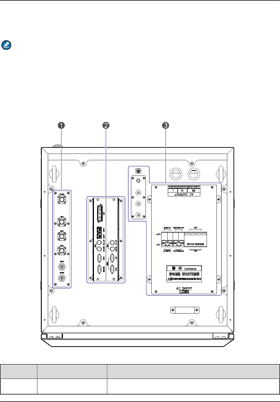
2.1 Interface Units of 4-carrier Base Station
The interface units on the top of the cabinet consist of the antenna connector, extended interface
board (EIB) and power supply interface. See Figure 2-1.
Figure 2-1 Interface Units of 4-carrier Base Station
No. Name Description
1 Antenna Connector
It contains the GPS antenna connector, RX antenna
Product Controls
Owner's Manual
10
No. Name Description
connector and TX antenna connector.
2 EIB
It contains the core network interface, cabinet expansion
interface and monitor interface.
3 Power Supply Interface /
Table 2-1 Descriptions on Interface Units of 4-carrier Base Station
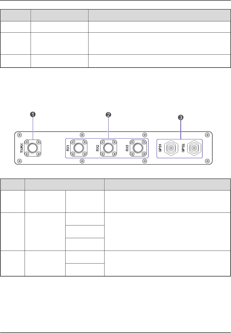
2.1.1 Antenna Connector
The antenna connector is illustrated below.
Figure 2-2 Antenna Connector of 4-carrier Base Station
No. Name Description
1
TX Antenna
Connector TX/RX N-connector (female)
2
RX Antenna
Connector
RX1
N-connector (female)
RX2
RX3
3
GPS Antenna
Connector
GPS1
N-connector (female)
GPS2
Table 2-2 Descriptions on Antenna Connector of 4-carrier Base Station
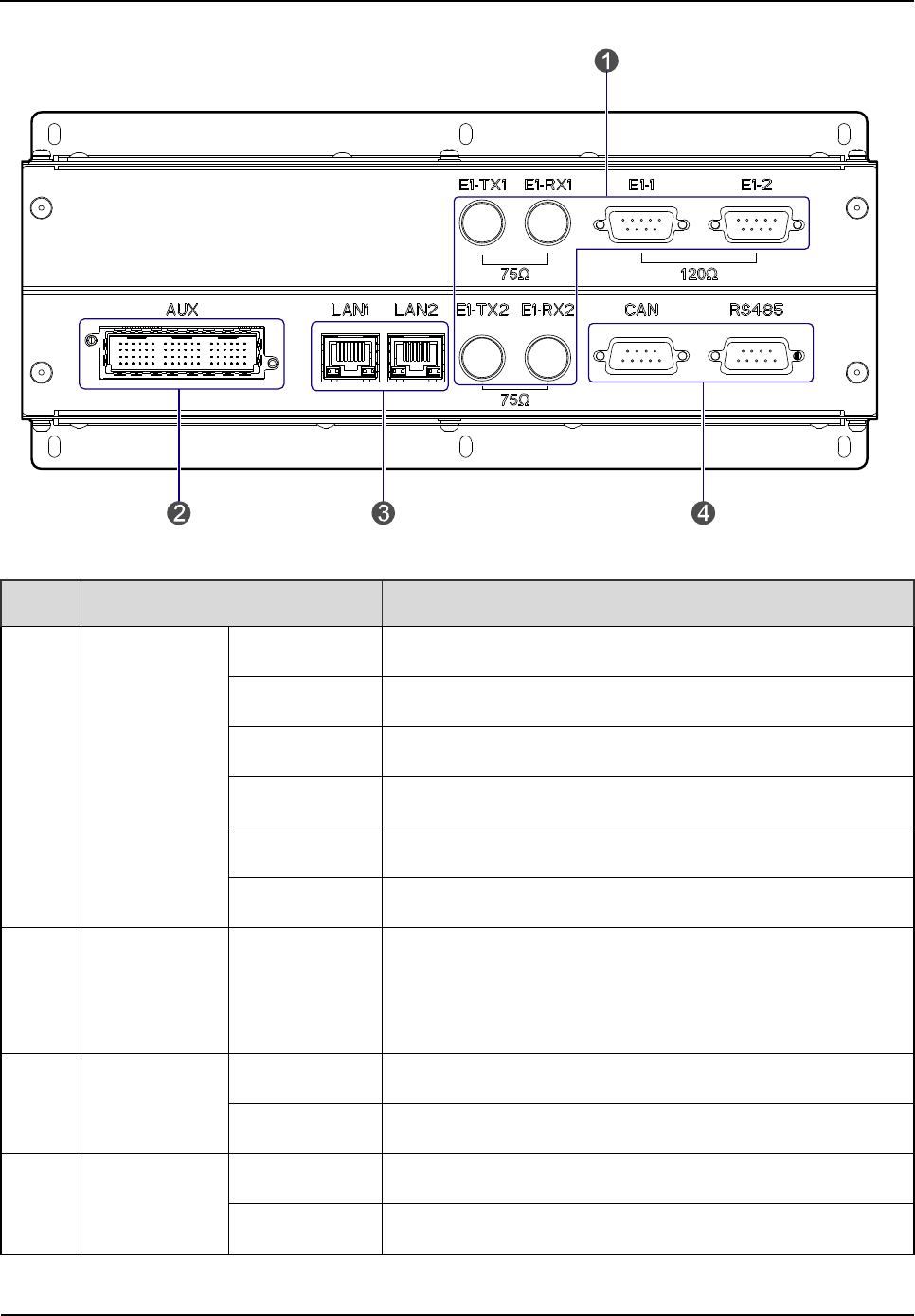
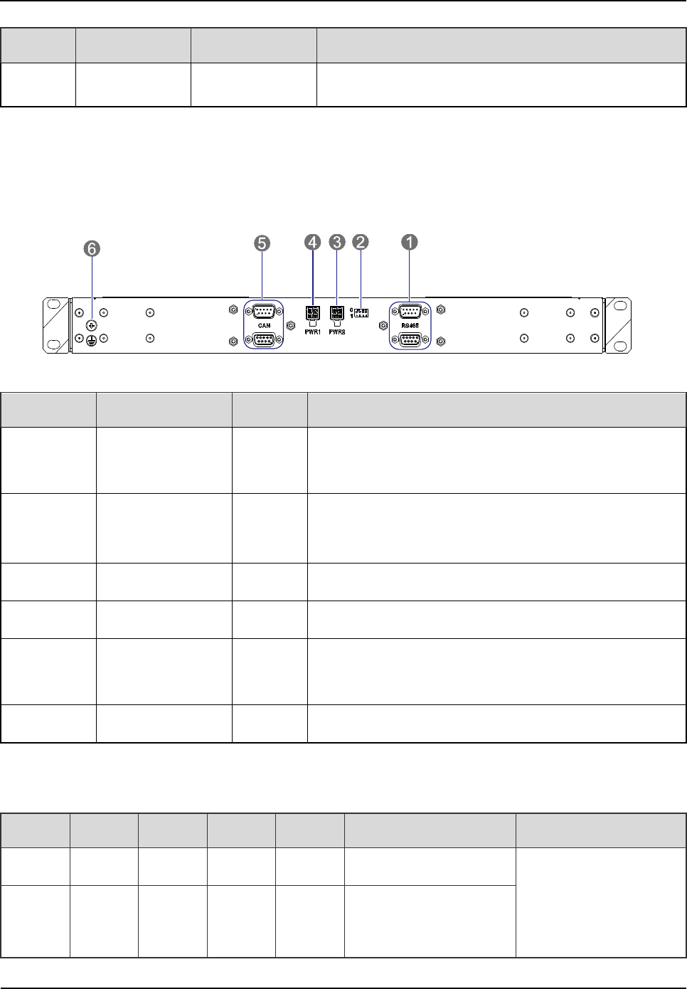
2.1.2 EIB
The EIB is illustrated below.
Owner's Manual
Product Controls
11
Figure 2-3 EIB of 4-carrier Base Station
No. Name Description
1 E1 Interface
E1-TX1 BNC-connector (female)
E1-RX1 BNC-connector (female)
E1-1 DB9-connector (female)
E1-2 DB9-connector (female)
E1-TX2 BNC-connector (female)
E1-RX2 BNC-connector (female)
2
Cabinet
Expansion
Interface
AUX Dedicated 72-pin interface
3 Ethernet
Interface
LAN1 RJ-45 connector
LAN2 RJ-45 connector
4 Monitor
Interface
CAN DB9-connector (female)
RS485 DB9-connector (female)
Table 2-3 Descriptions on EIB of 4-carrier Base Station
Product Controls
Owner's Manual
12
Core Network Interface
The core network interface contains the 4-path E1 interface and 2-path Ethernet interface.
Cabinet Expansion Interface
The cabinet expansion interface has 8-path extended signals. It is applied to connect to four
interconnect relay units of another cabinet, in case of interconnecting two cabinets.
Monitor Interface
The monitor interface includes one CAN-BUS interface and one RS485 interface.
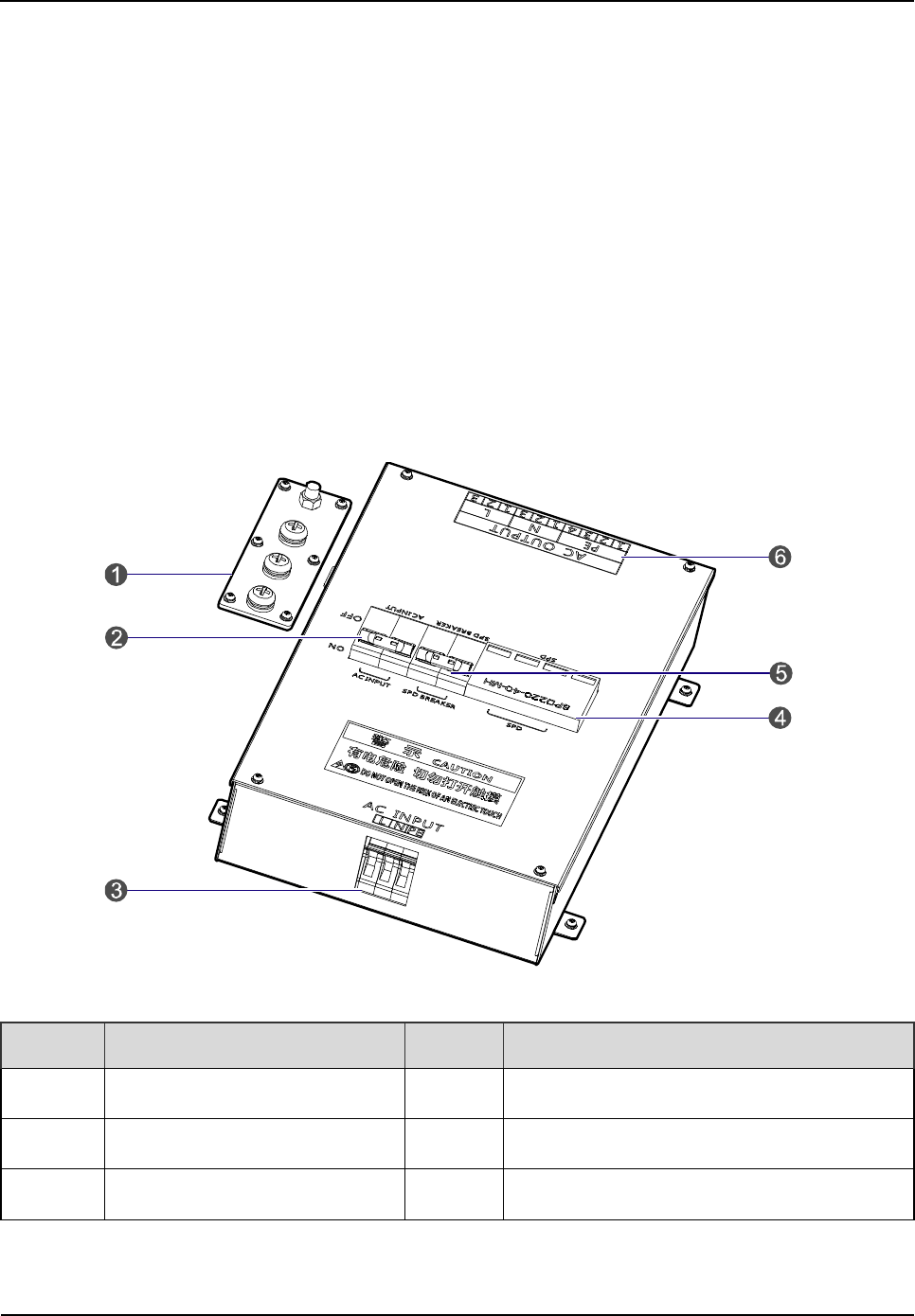
2.1.3 Power Supply Interface
The power supply interface is illustrated below.
Figure 2-4 Power Supply Interface of 4-carrier Base Station
No. Name No. Name
1 Ground Bar 2 AC Input Breaker
3 AC Input Terminal 4 Surge Protection Device (SPD)
5 SPD Breaker 6 AC Output Terminal
Table 2-4 Descriptions on Power Supply Interface of 4-carrier Base Station
Owner's Manual
Product Controls
13
2.2 Cartridge
In accordance with the IEC60297 standard, the cartridge is 19 inches in width and 7U in height. Each
cartridge can accommodate four CHUs, two BSCUs and two PSUs.
The slot 5 and slot 6 of the main chassis are available for the BSCU. See Figure 2-5.
C
H
U
02
P
S
U
08
P
S
U
07
B
S
C
U
06
C
H
U
01
B
S
C
U
05
C
H
U
04
C
H
U
03
Figure 2-5 Full Configuration for MC
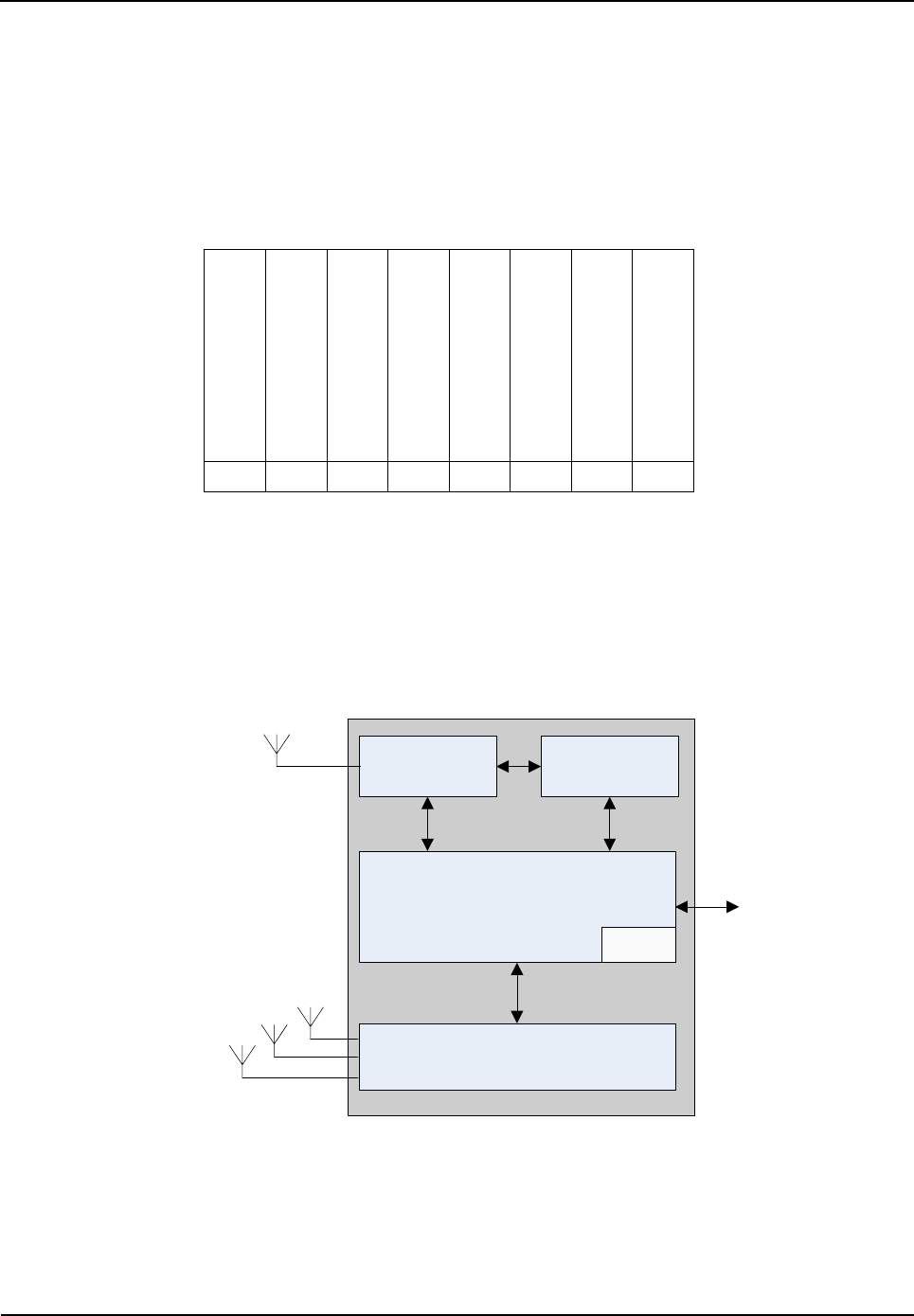
2.3 Channel Unit (CHU)
The CHU logically includes power amplification, TX excitation unit, baseband signal processing unit
and diversity receiver. See Figure 2-6.
RX Antenna 3
PA TX Excitation
Unit
Baseband Signal Processing Unit
Power
Diversity Receiver
TX Antenna
ICB
RX Antenna 2
RX Antenna 1
Figure 2-6 Logical Architecture of CHU
2.3.1 Function
The CHU processes and converts protocols on the physical layer and data link layer of the DMR air
interface. Physically, it consists of channel control board (CHB), TX board (TXB) and RX board (RXB).
Product Controls
Owner's Manual
14
CHB: capable of signaling processing, channel encoding/decoding, interleaving and de-interleaving,
modulation/demodulation, RF signal loop-back test and fail-soft.
TXB: capable of modulation, upward frequency conversion, filtering and D/A conversion from carrier
baseband signal to RF signal, as well as the downlink signal amplification.
RXB: capable of filtering, demodulation, downward frequency conversion, AGC and A/D conversion
from three-path carrier signal to baseband signal, as well as uplink signal amplification.
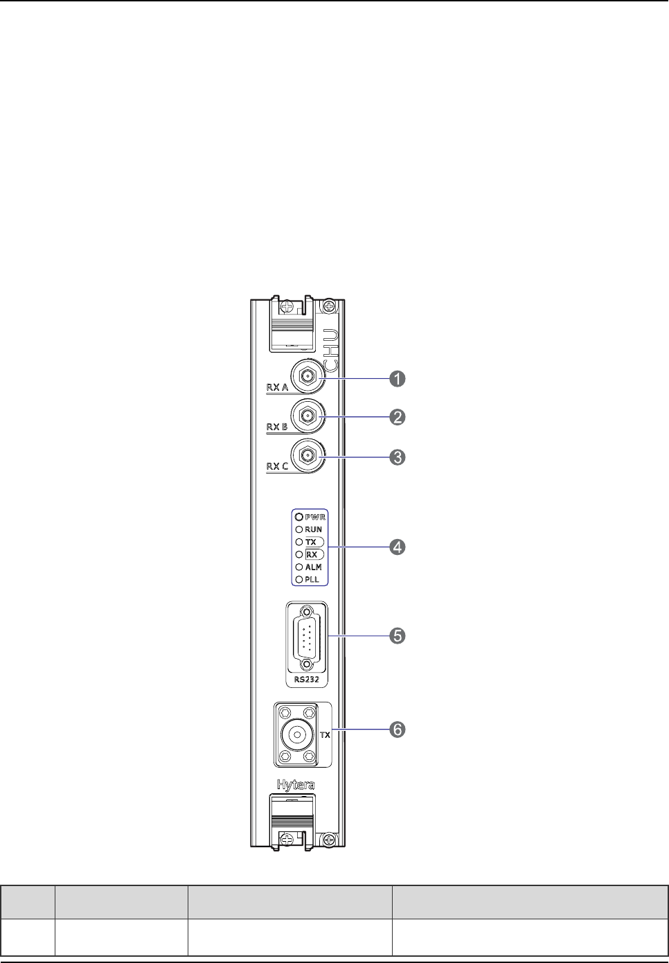
2.3.2 Front Panel
The front panel of the CHU is illustrated below.
Figure 2-7 Front Panel of CHU
No. Name Description Remarks
1 RXA Diversity RX antenna input SMA-connector (female)

Owner's Manual
Product Controls
15
No. Name Description Remarks
2 RXB RX antenna input SMA-connector (female)
3 RXC Diversity RX antenna input SMA-connector (female)
4 LEDs LED indicator /
5 RS232 Debug interface DB9-connector (female)
6 TX Transmission N-connector (female)
Table 2-5 Description on Front Panel of CHU
2.3.3 LED Indicator
The CHU indicators are described in Table 2-6.
LED
Indicator Color Status Description (in working mode) Description (in sleep mode)
PWR Green
On The CHU is powered on. The CHU is powered on.
Off The CHU is powered off. The CHU is powered off.
RUN Green
Flashing The CHU runs properly. \
Off The CHU does not run properly. The CHU is in sleep mode.
TX Green
On Data is present on downlink slot
2 of the CHU. \
Off Data is present on downlink slot
1 of the CHU. The CHU is in sleep mode.
RX Green
On Data is present on the uplink of
the CHU.
Data is present on the uplink of
the CHU.
Off No data is present on the uplink
of the CHU.
No data is present on the
uplink of the CHU.
ALM Red
On The CHU software is faulty. The CHU software is faulty.
Off The CHU runs properly. The CHU runs properly.
PLL Red On An alarm is given for PLL unlock.
An alarm is given for PLL
Product Controls
Owner's Manual
16
LED
Indicator Color Status Description (in working mode) Description (in sleep mode)
unlock.
Off The CHU runs properly. The CHU runs properly.
Table 2-6 Descriptions on CHU Indicators
Note
In sleep mode, the CHU can receive inbound data. However, if the downlink channel is in use, the
CHU will turn to operation mode; if the downlink channel is released, the CHU will turn to sleep
mode.
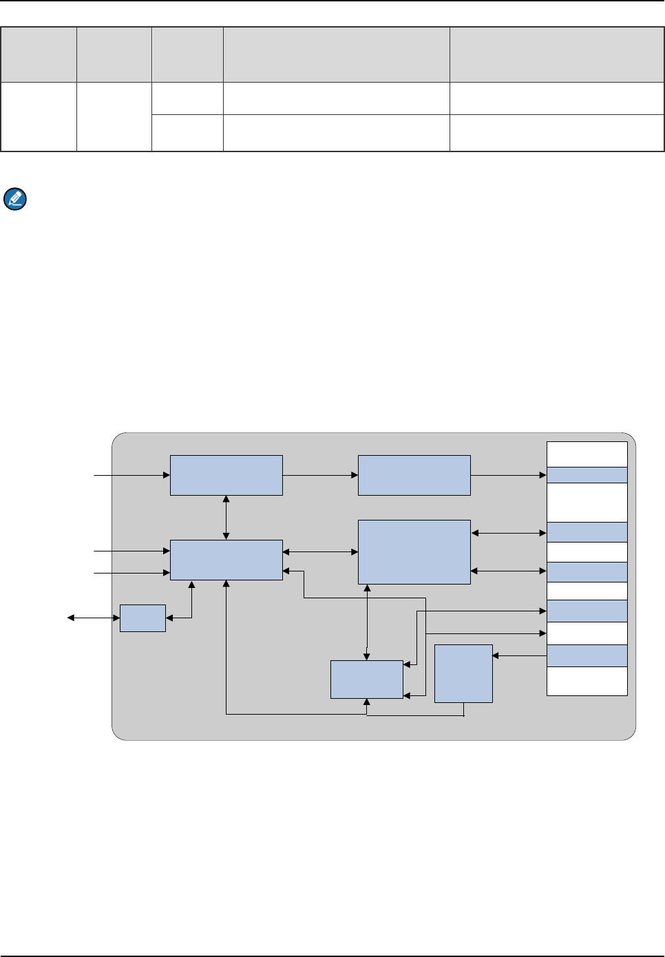
2.4 Base Station Controller Unit (BSCU)
The BSCU logically consists of GPS board, main control board, synchronizing buffer, Ethernet switch,
micro processor unit and power supply. See Figure 2-8.
BSCU-GPSB
GPS Board
BSCU-MCB
Main Control Board
Synchronizing Buffer
Ethernet Switch
RS232
MPU
Micro
Processor Unit
Power
Supply
CLK,CNT
LAN1
LAN11
CAN
...
RS-485
DC-IN
BSCU ICB
GPS
RS232
VGA
USB
Figure 2-8 Logic Architecture of BSCU
2.4.1 Function
The BSCU is to manage the wireless link resources within the coverage and allocate them for different
call services.
Owner's Manual
Product Controls
17
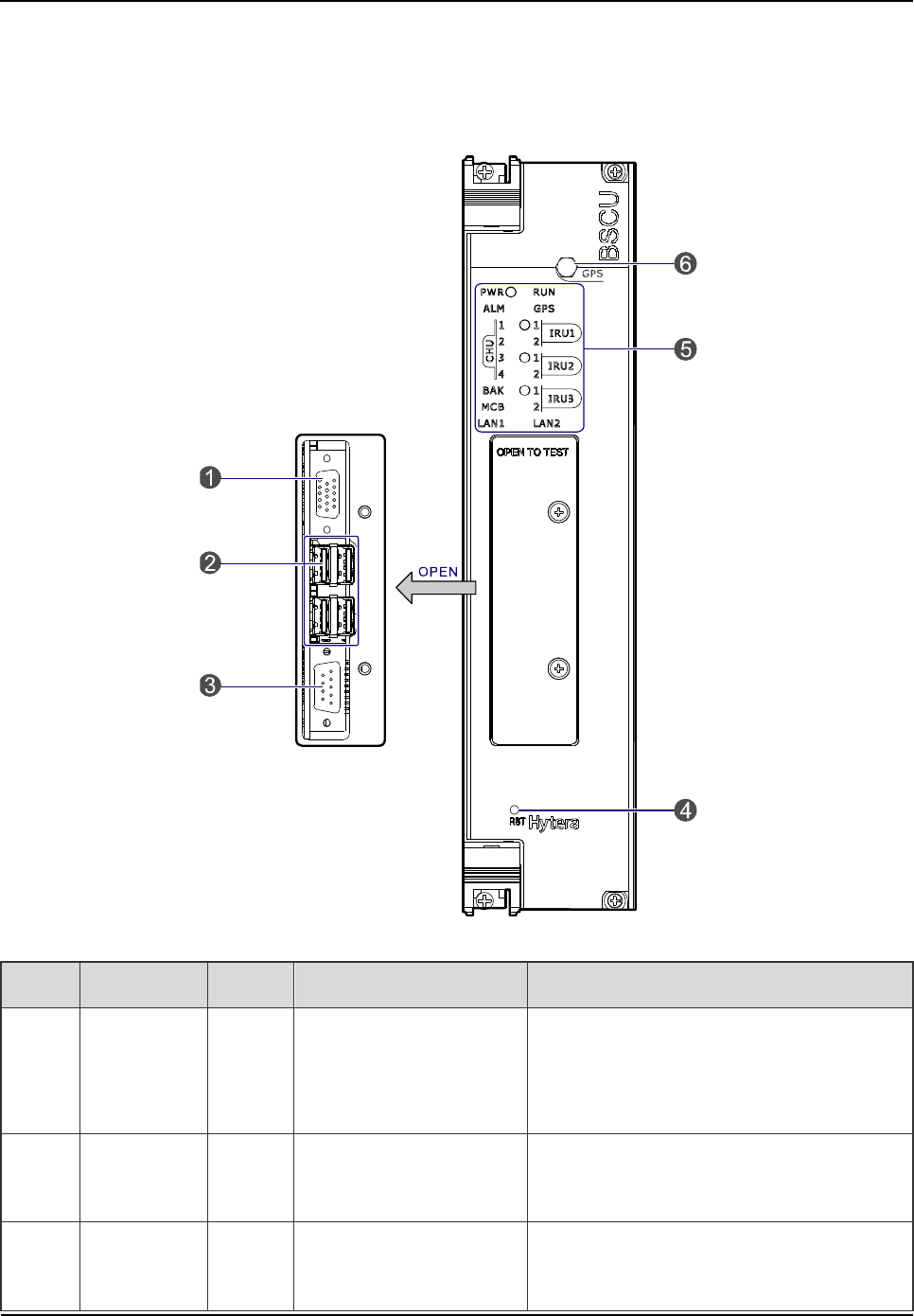
2.4.2 Front Panel
The front panel of the BSCU is illustrated below.
Figure 2-9 Front Panel of BSCU
No. Name Qty. Description Description
1
Video
graphics
array
1 For debugging DB15-connector (female)
2 USB
Interface 4 For debugging A-connector (female)
3 RS232
Interface 1 For debugging DB9-connector (male)

Product Controls
Owner's Manual
18
No. Name Qty. Description Description
4 RST Key 1 BSCU reset /
5 LEDs 1 LED indicator /
6 SMA
Interface 1 GPS signal input SMA-connector (female)
Table 2-7 Descriptions on Front Panel of BSCU
2.4.3 LED Indicator
The BSCU indicators are described in Table 2-8.
LED Indicator Color Status Description
PWR Green
On The BSCU is powered on.
Off The BSCU is powered off.
RUN Green
Flashing rapidly The BSCU is working in master mode.
Flashing slowly The BSCU is working in slave mode.
Off The BSCU is being initialized or malfunctions.
GPS Green
Flashing Functions are disabled locally.
On Functions are disabled via GPS.
Off Functions are enabled via GPS.
ALM Red
On The BSCU is alarming.
Off The BSCU works properly.
CHU1~4 Green
On The link between BSCU and CHU is present.
Flashing Data is being transmitted or received over the link
between BSCU and CHU.
Off
The link is abnormal or not connected between
BSCU and CHU.
IRU1~3 Green
On The link between BSCU and IRU is present.
Flashing Data is being transmitted or received over the link

Owner's Manual
Product Controls
19
LED Indicator Color Status Description
between BSCU and IRU.
Off
The link is abnormal or not connected between
BSCU and IRU.
BAK Green
On
The link between the standby BSCU and active
BSCU is present.
Flashing
Data is being transmitted or received over the link
between the standby BSCU and active BSCU.
Off The link is abnormal or not connected between the
standby BSCU and active BSCU.
MCB Green
On The link between BSCU and MCB is present.
Flashing Data is being transmitted or received over the link
between BSCU and MCB.
Off
The link is abnormal or not connected between
BSCU and MCB.
LAN1~2 Green
On The link between BSCU and LNA is present.
Flashing Data is being transmitted or received over the link
between BSCU and LAN.
Off
The link is abnormal or not connected between
BSCU and LAN.
Table 2-8 Descriptions on BSCU Indicators
2.5 Power Supply Unit (PSU)
The PSU consists of power monitor board, power module and LED indicators.
2.5.1 Function
Functions are described in Table 2-9.

Product Controls
Owner's Manual
20
No. Item Description
1 External Power Supply Input 90~264V AC 47~63Hz
2
Voltage Output (for main
device) 13.5V DC
3 Voltage Output (for CHU PA) HVCC (13.5V DC)
4 Voltage Output (for other
CHU power supply) LVCC (13.5V DC)
5 Voltage Output (for BSCU) BSC_V (13.2V DC)
6 I/O Interface
It is connected to 2 BSCUs and outputs three
channel signals. The first two are used for resetting
PSU, and the last for installation status of PSU.
7 Monitor Interface
It is connected to 2 BSCUs.
It is connected to 2 BSCUs.
Table 2-9 Descriptions on PSU
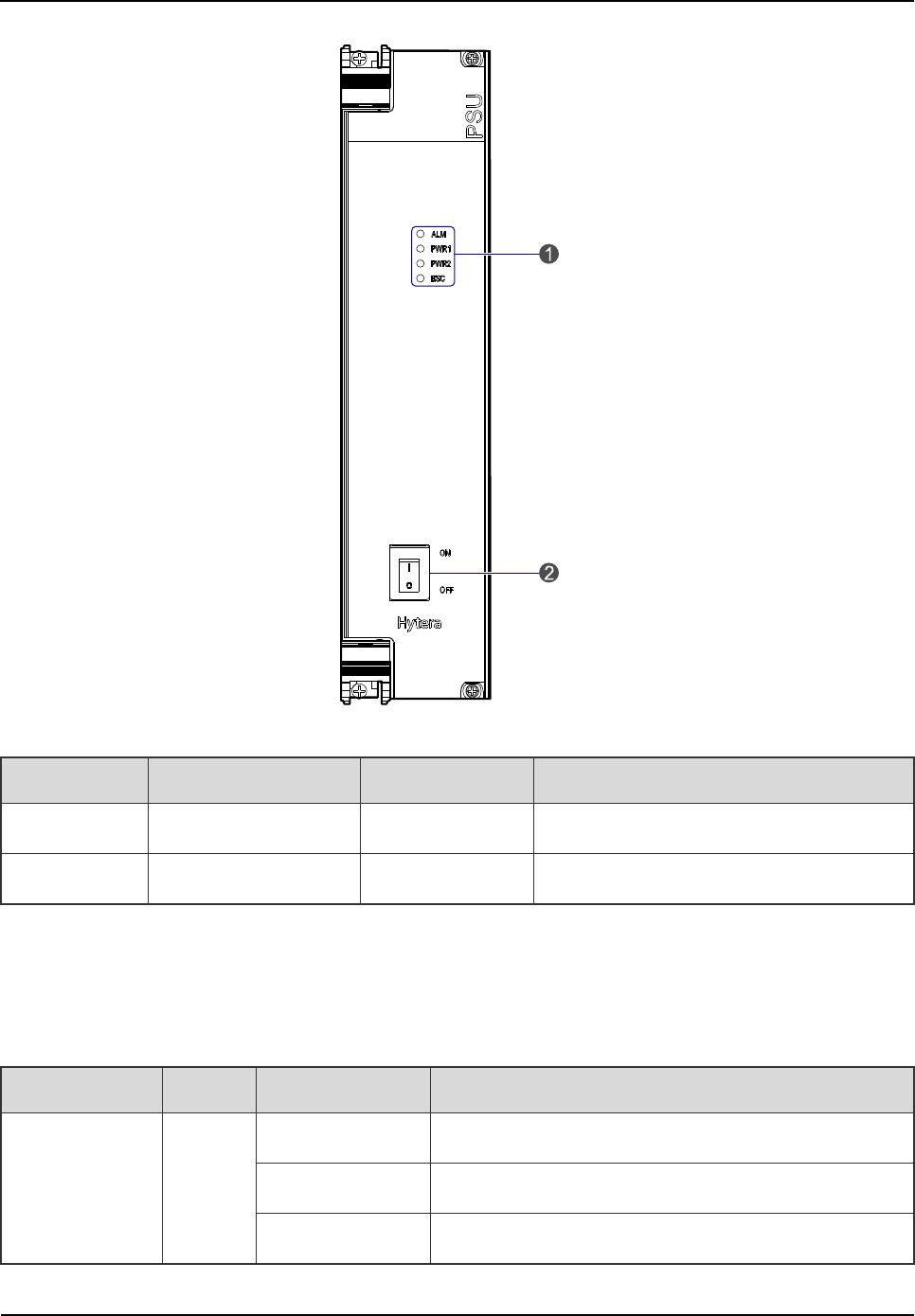
2.5.2 Front Panel
The front panel of the PSU is illustrated below.
Owner's Manual
Product Controls
21
Figure 2-10 Front Panel of PSU
No. Name Qty. Description
1 LEDs 1 LED indicator
2 ON/ OFF Switch 1 Power switch
Table 2-10 Descriptions on Front Panel of PSU
2.5.3 LED Indicator
The PSU indicators are described in Table 2-11.
LED Indicator Color Status Description
ALM Red
Glowing solidly A major alarm exists.
Flashing A minor alarm exists.
Off No alarm exists.

Product Controls
Owner's Manual
22
LED Indicator Color Status Description
PWR1 Green
Glowing solidly The first power module outputs normally.
Flashing slowly
The first power module outputs HVCC or LVCC
alarm.
Flashing rapidly
The first power module outputs HVCC and LVCC
alarm simultaneously.
Off The first power module is not installed.
PWR2 Green
Glowing solidly The second power module outputs normally.
Flashing slowly The second power module outputs HVCC or LVCC
alarm.
Flashing rapidly The second power module outputs HVCC and LVCC
alarm simultaneously.
Off The second power module is not installed.
BSC Green
Glowing solidly The voltage for the BSC is normal.
Flashing An alarm is issued due to over-voltage or low voltage
for the BSC.
Off The first or second power module is not installed.
Table 2-11 Descriptions on PSU Indicators
Note
The power module has two outputs including HVCC and LVCC.
2.6 Interconnect Backboard (ICB)
It connects the power, synchronization clock module, signaling gateway, voice and data gateway,
monitor module and I/O interface.
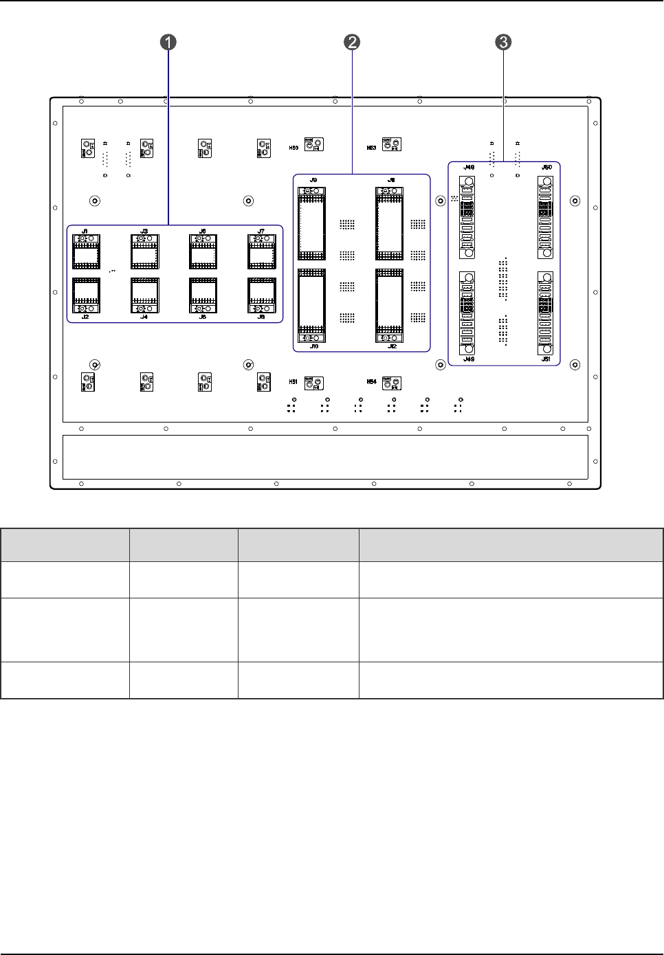
2.6.1 Front View
The front side and interfaces of the ICB are described below.
Owner's Manual
Product Controls
23
Figure 2-11 Front View of ICB
No. Name Qty. Description
1 CHU Interface 4 For signal from CHU to ICB.
2 BSCU
Interface 2 For signal from BSCU to ICB.
3 PSU Interface 2 For signal from PSU to ICB.
Table 2-12 Descriptions on Front Interfaces of ICB
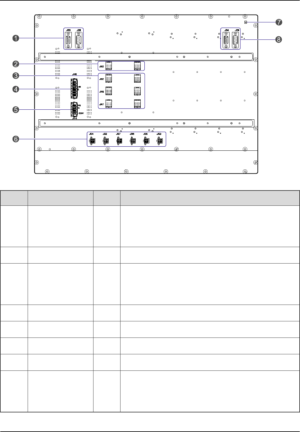
2.6.2 Rear View
The rear view and interfaces of the ICB are described below.
Product Controls
Owner's Manual
24
Figure 2-12 Rear View of ICB
No. Name Qty. Description
1
Monitor
Interconnection
Interface
2 CAN-BUS, DB9-connector (male/female)
2 EC Interface 2 For interconnecting two cartridges in the cabinet.
3 EIB Interface 6
For interconnecting two EC cartridges and four IRUs
between two cabinets. It also works as the signal interface
from EIB to ICB in the core network interface board.
4 DC Power Inlet 1 DC power input: -48V
5 AC Power Inlet 1 AC power input: 110V/220V
6 Power Outlet 6 DC power (+13.2V) for FAN and DIU.
7 DIP Switch 1 For setting the cartridge address.
8
Monitor
Interconnection
Interface
2 RS485 bus, DB9-connector (male/female)
Table 2-13 Descriptions on Rear Interfaces of ICB
Owner's Manual
Product Controls
25
The settings of the DIP switch are described in Table 2-14.
No. 4 3 2 1 Description Note
1 X ON X ON Address for the main chassis
X: reserved.
2 X ON X OFF
Address for the first extended
chassis
3 X OFF X ON
Address for the second extended
chassis
4 X OFF X OFF
Address for the third extended
chassis
Table 2-14 DIP Switch Settings for ICB
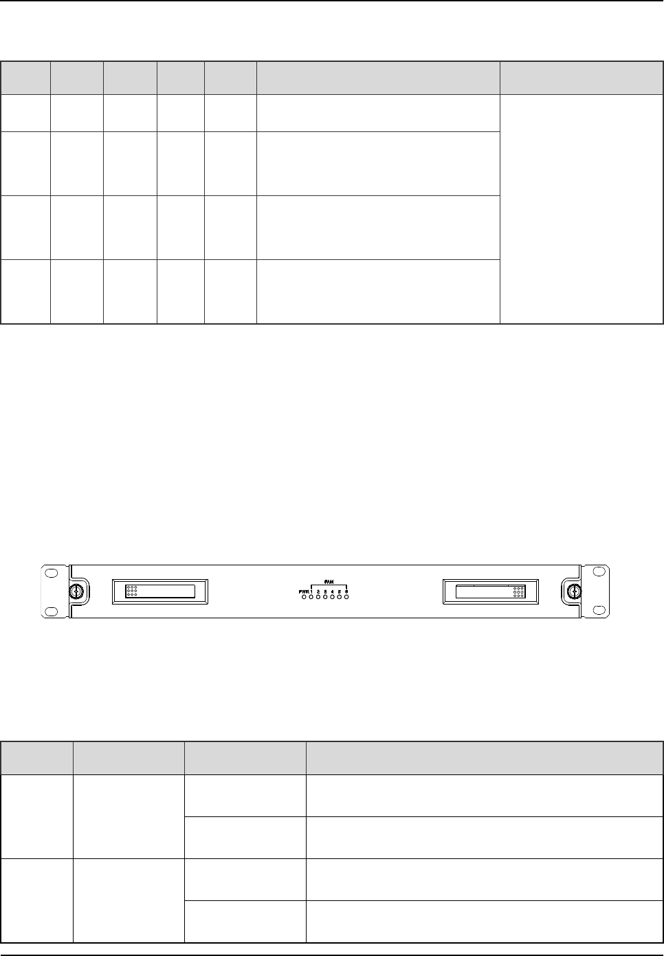
2.7 FAN
The FAN consists of a fan cartridge and a pluggable fan tray, and can accommodate six fans. In the
fan tray, three temperature sensors are installed.
2.7.1 Front Panel
The front panel of the FAN is illustrated below.
Figure 2-13 Front Panel of FAN
2.7.2 LED Indicator
The FAN indicators are described in Table 2-15.
Name Color Status Description
PWR Red
On The FAN is powered on.
Off The FAN is powered off.
1~6 Green
On The fan works properly.
Off The fan is out of operation or not installed.
Product Controls
Owner's Manual
26
Name Color Status Description
Flashing The fan is faulty.
Table 2-15 Descriptions on FAN Indicators
2.7.3 Rear Panel
The rear panel of the FAN is illustrated below.
Figure 2-14 Rear Panel of FAN
No. Name Qty. Description
1
RS485 Monitor
Interface 2 For connecting ICB and DIU. DB9-connector
(male/female)
2 DIP Switch 1 For setting the FAN address. For details, please refer
to Table 2-17.
3 Power Inlet 1 1 For connecting ICB.
4 Power Inlet 2 1 For connecting ICB.
5
CAN Monitor
Interface 2 For connecting ICB and DIU. DB9-connector
(male/female)
6 Ground Interface 1 /
Table 2-16 Descriptions on Rear Panel of FAN
The settings of the DIP switch are described in Table 2-17.
No. 1 2 3 4 Description Remarks
1 X X ON ON The first FAN address
X: reserved.
2 X X OFF ON
The second FAN
address
Owner's Manual
Product Controls
27
No. 1 2 3 4 Description Remarks
3 X X ON OFF The third FAN address
4 X X OFF OFF
The fourth FAN
address
Table 2-17 DIP Switch Settings for FAN
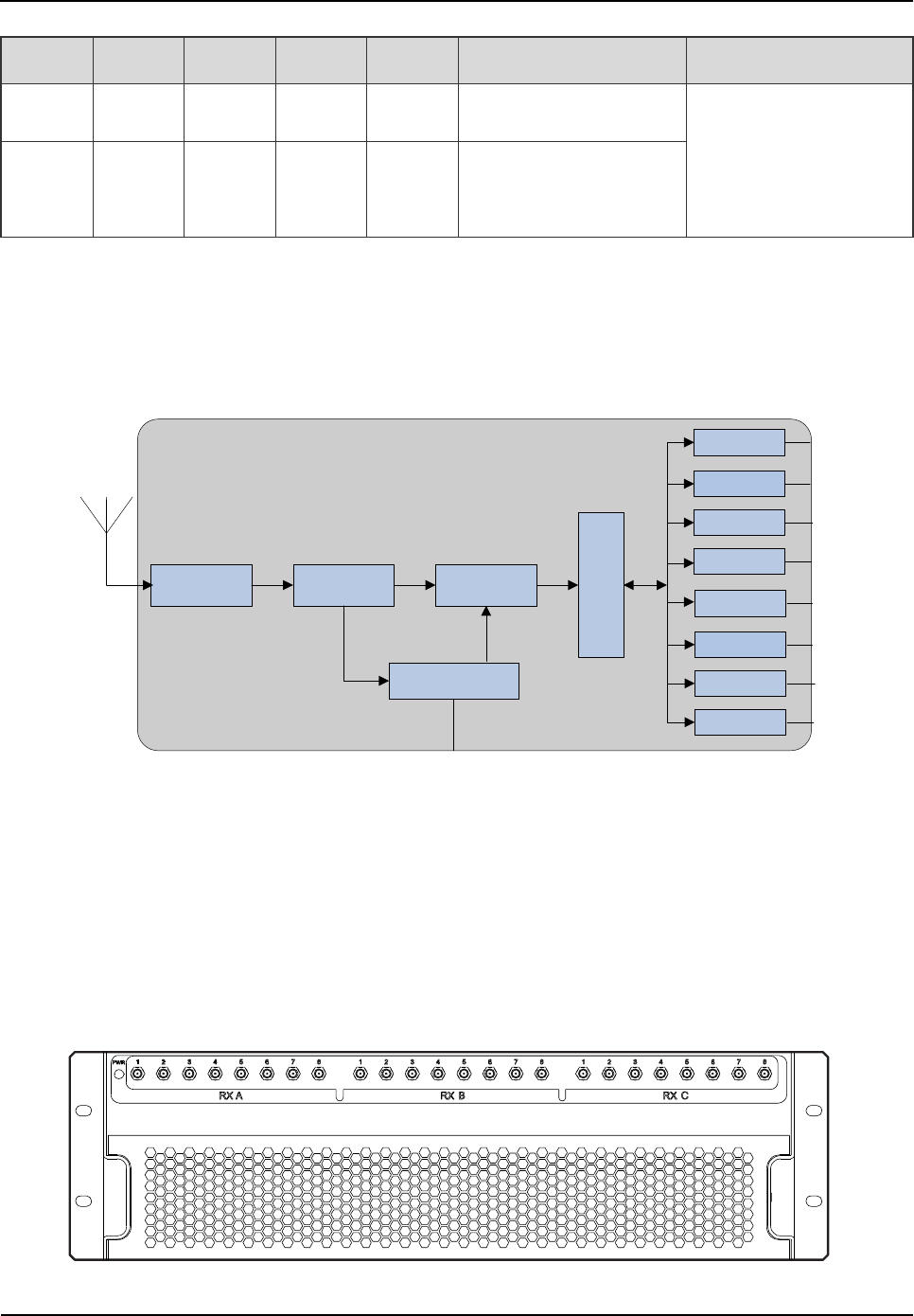
2.8 Divider Unit (DIU)
The DIU is 3U or 1U in height. The logical diagram is shown below.
Band-pass
Filter LNA Digital
Attenuator
Power
Divider
RX
RX
RX
RX
CAN/RS485
RX
RX
RX
RX
Figure 2-15 Logical Diagram of DIU
2.8.1 Function
The DIU is to assign the received signal to each transceiver.
2.8.2 Front Panel
The front panel of the DIU is illustrated below.
Figure 2-16 Front Panel of DIU
Product Controls
Owner's Manual
28
No. Name
Qty. Description Remarks
1 RXA 8 Diversity RX antenna output SMA-connector (female)
2 RXB 8 RX antenna output SMA-connector (female)
3 RXC 8 Diversity RX antenna output SMA-connector (female)
Table 2-18 Descriptions on Front Panel of DIU
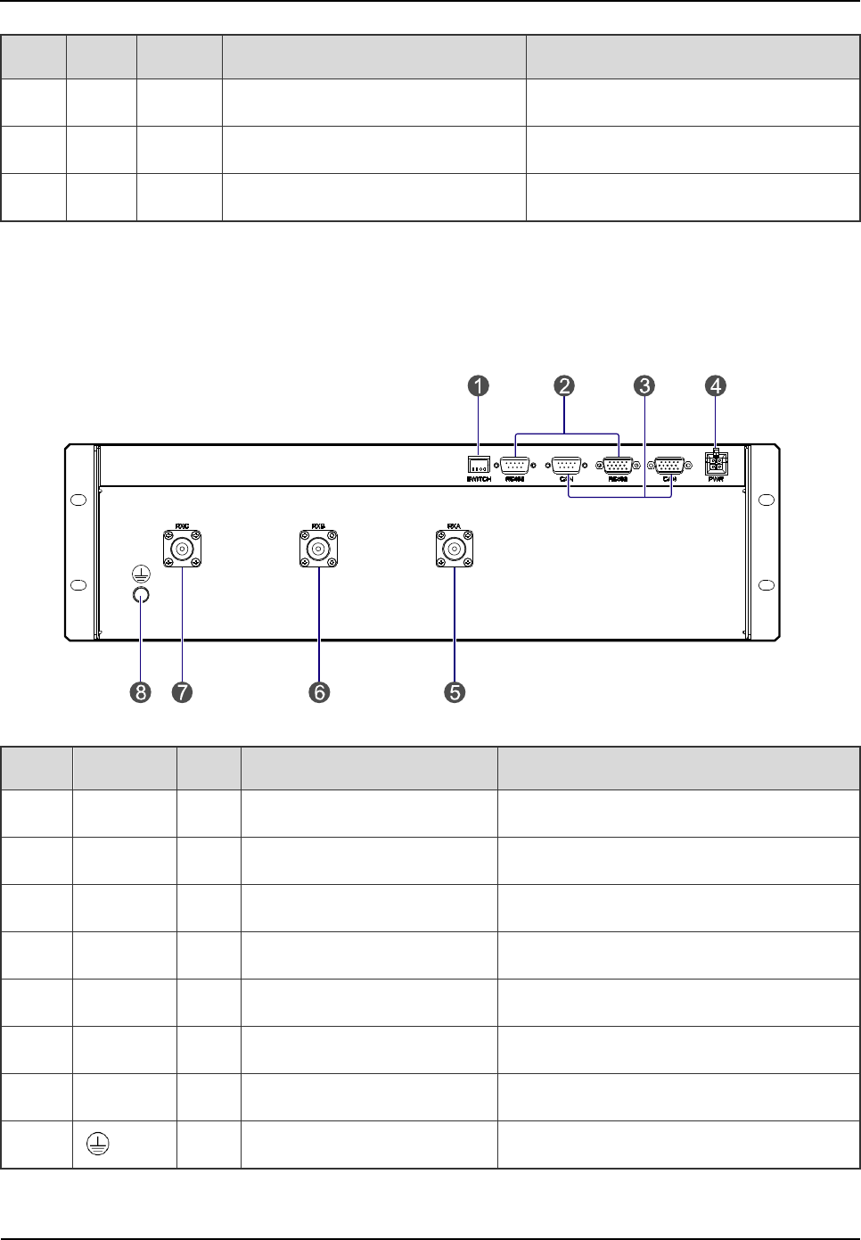
2.8.3 Rear Panel
The rear panel of the DIU is illustrated below.
Figure 2-17 Rear Panel of DIU
No. Name Qty. Description Remarks
1 SWITCH 1 DIP switch /
2 RS485 2 Monitor interface /
3 CAN-BUS 2 Monitor interface /
4 PWR 1 Power inlet /
5 RXA 1 Diversity RX antenna A N-connector (female)
6 RXB 1 RX antenna B N-connector (female)
7 RXC 1 Diversity RX antenna C N-connector (female)
8 1 Ground interface
Table 2-19 Descriptions on Rear Panel of DIU
Owner's Manual
Product Controls
29
The settings of the DIU address are described in Table 2-20.
No. 1 2 3 4 Description Remarks
1 ON ON X X The first DIU address
X: reserved.
2 ON OFF X X The second DIU address
3 OFF ON X X The third DIU address
4 OFF OFF X X The fourth DIU address
Table 2-20 DIU Address Settings
2.9 Router
2.9.1 Function
The router is a device that forwards message flow or packet data. However, if the IP-EI is employed,
no router will be required.
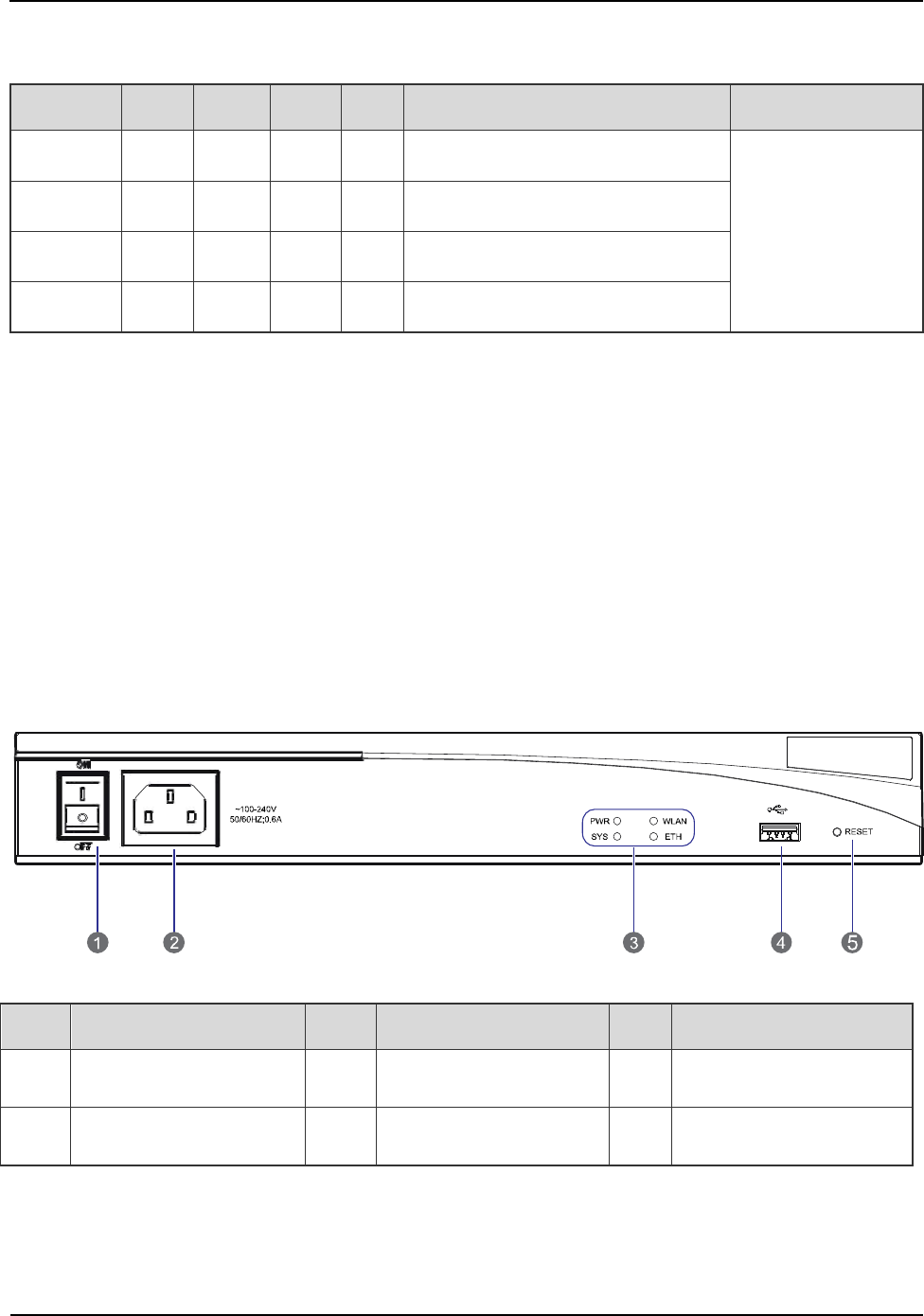
2.9.2 Front Panel
The front panel of the router is illustrated below.
Figure 2-18 Front Panel of Router
No. Name No. Name No. Name
1 Power Switch 2 Power Socket 3 LEDs
4 USB Interface 5 RESET Button / /
Table 2-21 Descriptions on Front Panel of Router
Product Controls
Owner's Manual
30
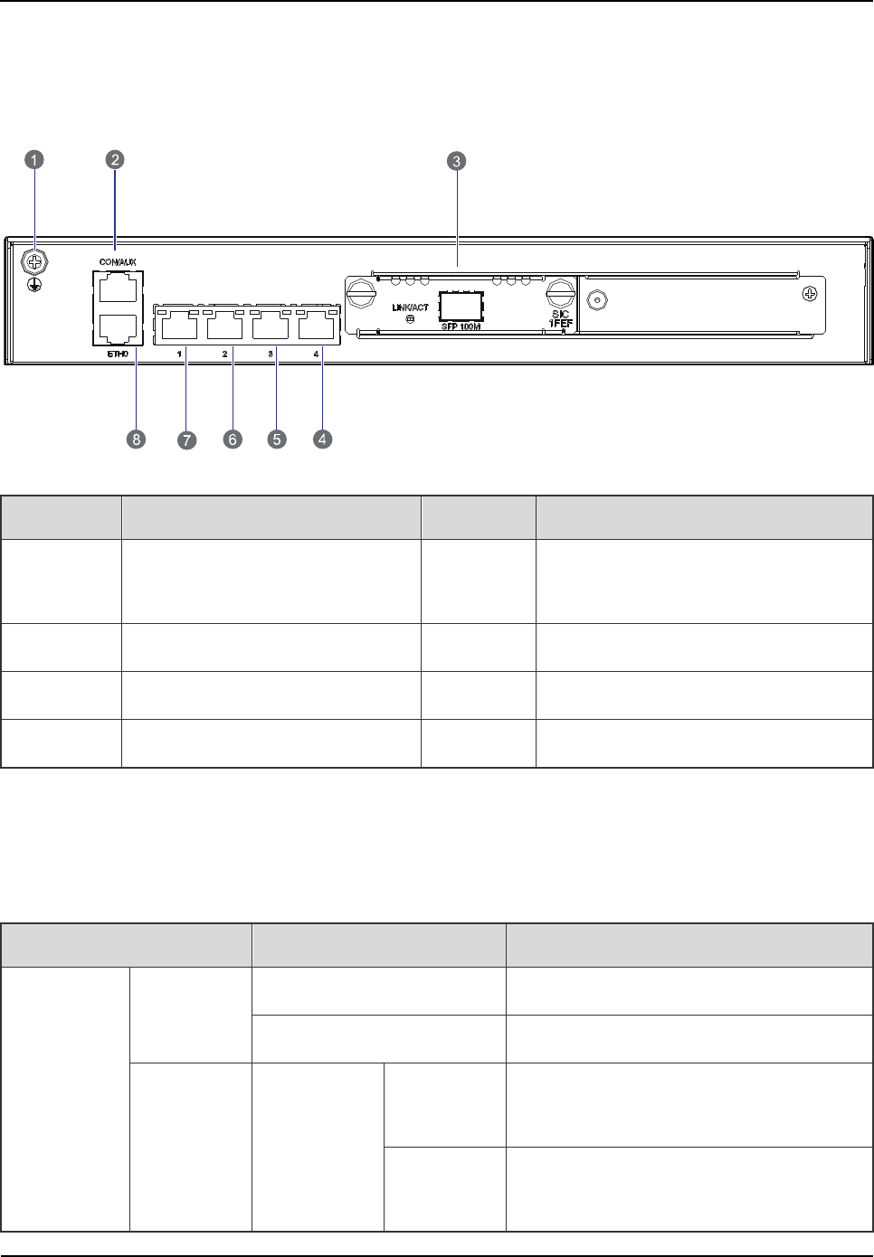
2.9.3 Rear Panel
The rear panel of the router is illustrated below.
Figure 2-19 Rear Panel of Router
No. Name No. Name
1 Ground Terminal 2
Console /Auxiliary Interface
(CON/AUX)
3 Fixed Ethernet Interface 0 4 Fixed Switch Interface 1
5 Fixed Switch Interface 2 6 Fixed Switch Interface 3
7 Fixed Switch Interface 4 8 SIC/DSIC Slot
Table 2-22 Descriptions on Rear Panel of Router
2.9.4 LED Indicator
The router indicators are described in Table 2-23.
Name Status Description
Front Panel
PWR
On The router is powered on.
Off The router is powered off.
SYS Green
Flashing
rapidly The router is starting.
Flashing
slowly The router works properly.

Owner's Manual
Product Controls
31
Name Status Description
Yellow Flashing
rapidly The router is faulty.
Off The router does not work properly.
ETH
On A link is present.
Flashing Data is being transmitted or received.
Off No link is present.
WLAN
Bootrom
Startup
On The extended BOOTROM is present.
Flashing The basic BOOTROM is present.
Router
Operation
Flashing
rapidly
The router is operating under large traffic
load.
Flashing
slowly The router is operating normally.
Off The router is faulty.
Rear Panel
LINK
On A link is present.
Off No link is present.
ACT
Flashing Data is being transmitted or received.
Off No data is being transmitted or received.
Table 2-23 Descriptions on Router Indicators
2.10 IP-E1
If a router is employed, no IP-EI will be required.
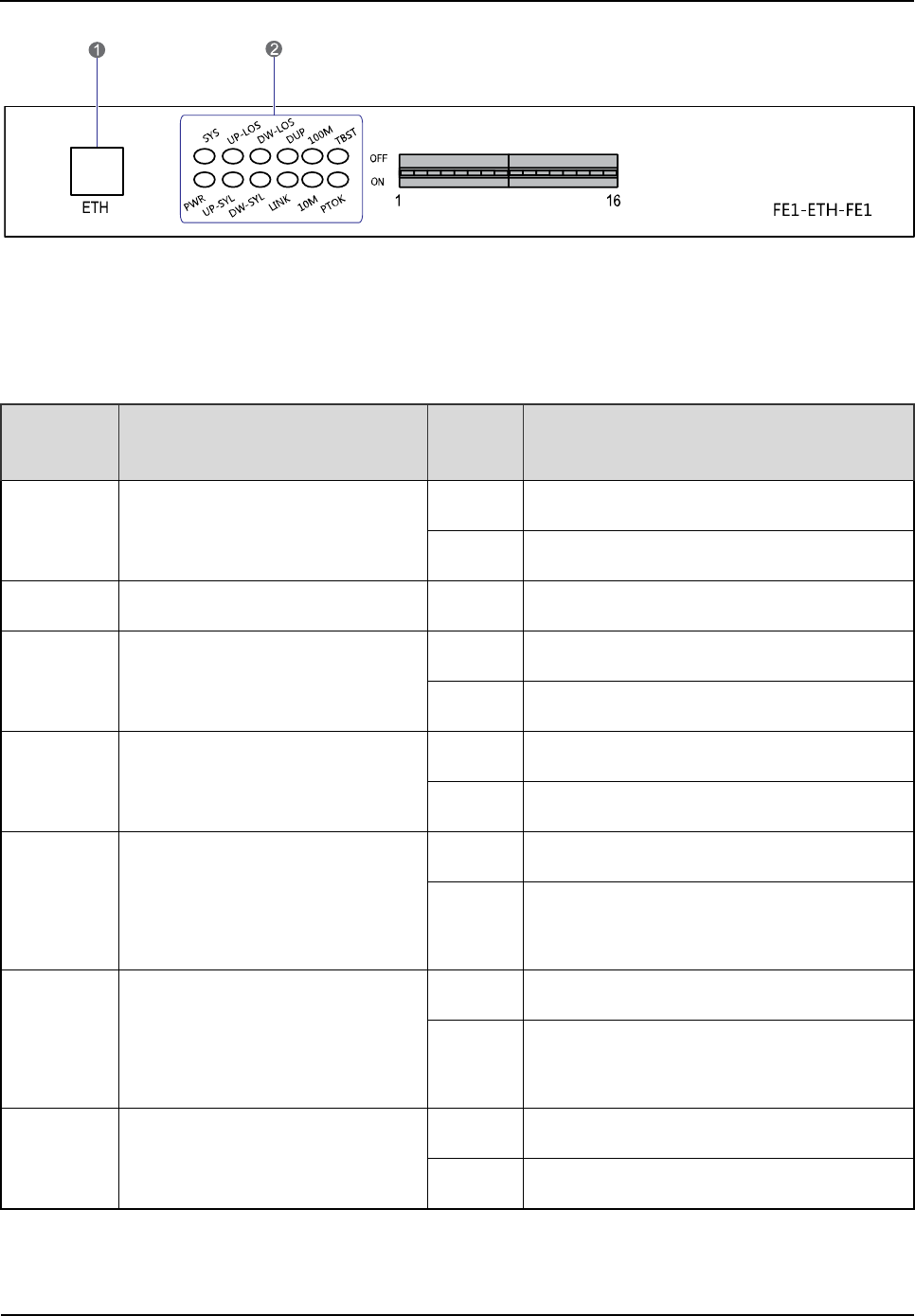
2.10.1 Front Panel
The front panel of the IP-EI is illustrated below.
Product Controls
Owner's Manual
32
Figure 2-20 Front Panel of IP-E1
2.10.2 LED Indicator
The IP-E1 indicators are described in Table 2-24.
LED
Indicator Name Status Description
PWR Power Indicator
On The IP-E1 is powered on.
Off The IP-E1 is powered off.
SYS / / Reserved
LNK Ethernet Indicator
On The network link is connected properly.
Off The network link is disconnected.
DUP Full Duplex/Half Duplex Indicator
On The IP-E1 is working in full duplex mode.
Off The IP-E1 is working in half duplex mode.
100M
Operating Mode and Data
TX/RX Indicator
On A 100 Mbps link is present.
Flashing Data is being received or transmitted at a
rate of 100Mbps.
10M
Operating Mode and Data
TX/RX Indicator
On A 10 Mbps link is present.
Flashing Data is being received or transmitted at a
rate of 10Mbps.
LOS1 EI Uplink Alarm Indicator
On The alarm of Local E1 uplink occurs.
Off No alarm exists.
Table 2-24 Descriptions on IP-E1 Indicators
Owner's Manual
Product Controls
33
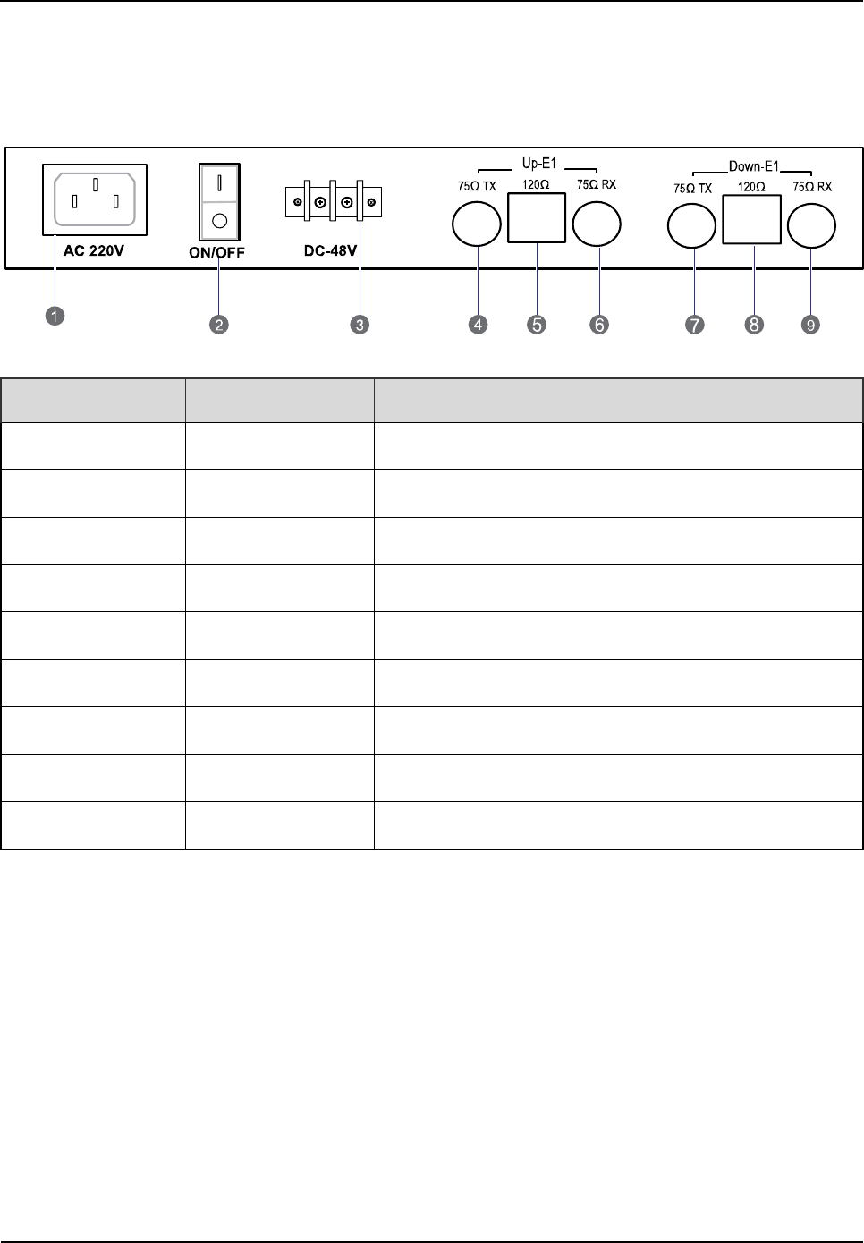
2.10.3 Rear Panel
The rear panel of the IP-E1 is illustrated below.
Figure 2-21 Rear Panel of IP-E1
No. Name Description
1 AC 220V AC power inlet (optional)
2 ON/OFF Power switch
3 DC -48V DC power inlet (optional)
4 75Ω/Up(TX) E1-75ohm unbalanced port, E1 signal output.
5 120Ω/Up E1-
120ohm unbalanced port, E1 signal input and output.
6 75Ω/Up(RX) E1-75ohm unbalanced port, E1 signal input.
7 75Ω/Down(TX) E1-75ohm unbalanced port, E1 signal output.
8 120Ω/ Down E1-
120ohm unbalanced port, E1 signal input and output.
9 75Ω/ Down(RX) E1-75ohm unbalanced port, E1 signal input.
Table 2-25 Descriptions on Rear Panel of IP-E1
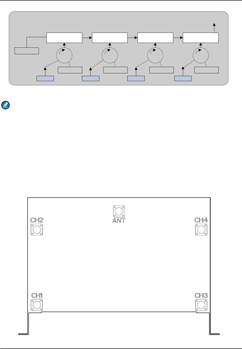
2.11 Combiner (COM)
The combiner is classified into broadband hybrid combiner, manual tune cavity combiner, and auto
tune cavity combiner. The broadband hybrid combiner is applied to the 2-carrier base station, while the
manual tune cavity combiner is applied to the base station with more than two carriers. The logical
diagram of the 4-port combiner is shown in Figure 2-22.
Product Controls
Owner's Manual
34
Cavity Resonator Cavity Resonator Cavity Resonator Cavity Resonator
50Ω
50Ω50Ω50Ω50Ω
CHU1 CHU2 CHU3 CHU4
COM Output
Figure 2-22 Logical Diagram of 4-port Combiner
Note
This section takes one type of combiner as an example.
2.11.1 Function
The combiner is used to integrate multiple carriers from the base station sub-system into one output
port to transmit by an antenna.
2.11.2 Rear Panel
The rear panel of the COM is illustrated below.
Figure 2-23 Rear Panel of COM

Owner's Manual
Product Controls
35
No. Name
Description Remarks
1 ANT COM output N-connector (female)
2 CH1 Carrier input 1 N-connector (female)
3 CH2 Carrier input 2 N-connector (female)
4 CH3 Carrier input 3 N-connector (female)
5 CH4 Carrier input 4 N-connector (female)
Table 2-26 Descriptions on Rear Panel of COM

Owner's Manual
Installation
37
3.2.1 Power Supply
Danger:
Some components of the power system carry hazardous voltage in operation. Direct contact or
indirect contact through moist objects with these components will result in fatal injury.
Never wear conductive objects such as watches, bracelets, rings and etc during operation.
Do use special tools in high voltage and AC operation.
Do keep moisture out of the power system during operation in moist environment.
The equipment should be well earthed in time to avoid damage by lightning strikes in thunderstorm.
Do turn off the power before assembly or disassembly
Do verify the compliance of the cable and cable label prior to connection.
Ensure that the equipment is well earthed before powering on.
Turn off the power immediately when water or moisture is found on the cabinet,
Make sure all switches of power distribution box are set to off before installation each module in the
cabinet
3.2.2 Working at Heights
Warning:
Cautions shall be taken to prevent objects from falling during working at heights.
Safety protection measures (e.g. wearing a hamlet or the safety belt) shall be taken.
The heat-retaining clothes shall be worn before operation in cold areas.
Make sure that the ladder is safe for use. Overweight on the ladder is strictly prohibited.
Protective measures shall be taken if the slant of the ladder is more than 5m or the ladder is placed
on a high ground (>3m)
Handle and use all equipment and tools with care to avoid falling.
3.3 Installation Preparation
3.3.1 Technical Files
The following table lists the files associated with hardware installation.

Installation
Owner's Manual
38
File type File Name Description
Instructional
file for
installation
Network Planning Drawing Provided by the R&
D engineers or
technical sales.
Site Survey Report It is filled by the investigation engineer on
site.
Manuals
DS-6210U5C4 PDT Trunking System
Shipped with the equipment
DS-6210U5C4
PDT Trunking Base
Station Hardware Description Manual
DS-6210U5C4
PDT Trunking Base
Station Service Manual
Other files Packing List Shipped with the equipment
Table 3-1 Technical Files
3.3.2 Personnel
Only the adequately trained personnel with satisfactory knowledge of the system can carry out the
installation and tuning. The number of installation persons is subject to engineering progress and
environment.
3.3.3 Tools
The following tools and meter are required before installation.
General
Tools
Claw hammer, slot type screwdriver, large Phillips screwdriver, wrench, paper knife,
connector board and A type ladder.
Special
Tools
ESD-preventive wrist strap, cable peeler and crimping pliers.
Meter Multimeter
Table 3-2 Tools and Meter
Owner's Manual
Installation
39
3.4 Unpacking Inspection
3.4.1 Check before Unpacking
After the equipment arrives at the installation site, you should:
Check against the packing list, including total amount, customer address, and etc.
Contact us in case of any mistake.
Check the packaging case is in good condition and not placed upside down.
If the outer package is damaged seriously or soaked, please contact us immediately.
Note:
To protect the equipment and investigate the cause, please properly keep the package box,
equipment and packing materials, and take photo.
If the above check results are good, unpack and check the equipment.
3.4.2 Unpacking Wooden Case
Caution:
Keep the wooden case far away from intense shock during transportation.
Never touch the parts with dirty glove during transportation.
If space permitting, carry the wooden case into or near the computer room before unpacking. This can
prevent the chassis from being damaged.
To unpack the wooden case, do as follows:
Step 1 Wear the ESD-preventive glove.
Step 2 Lay the wooden case horizontally on the ground. Do keep the side with frame down.
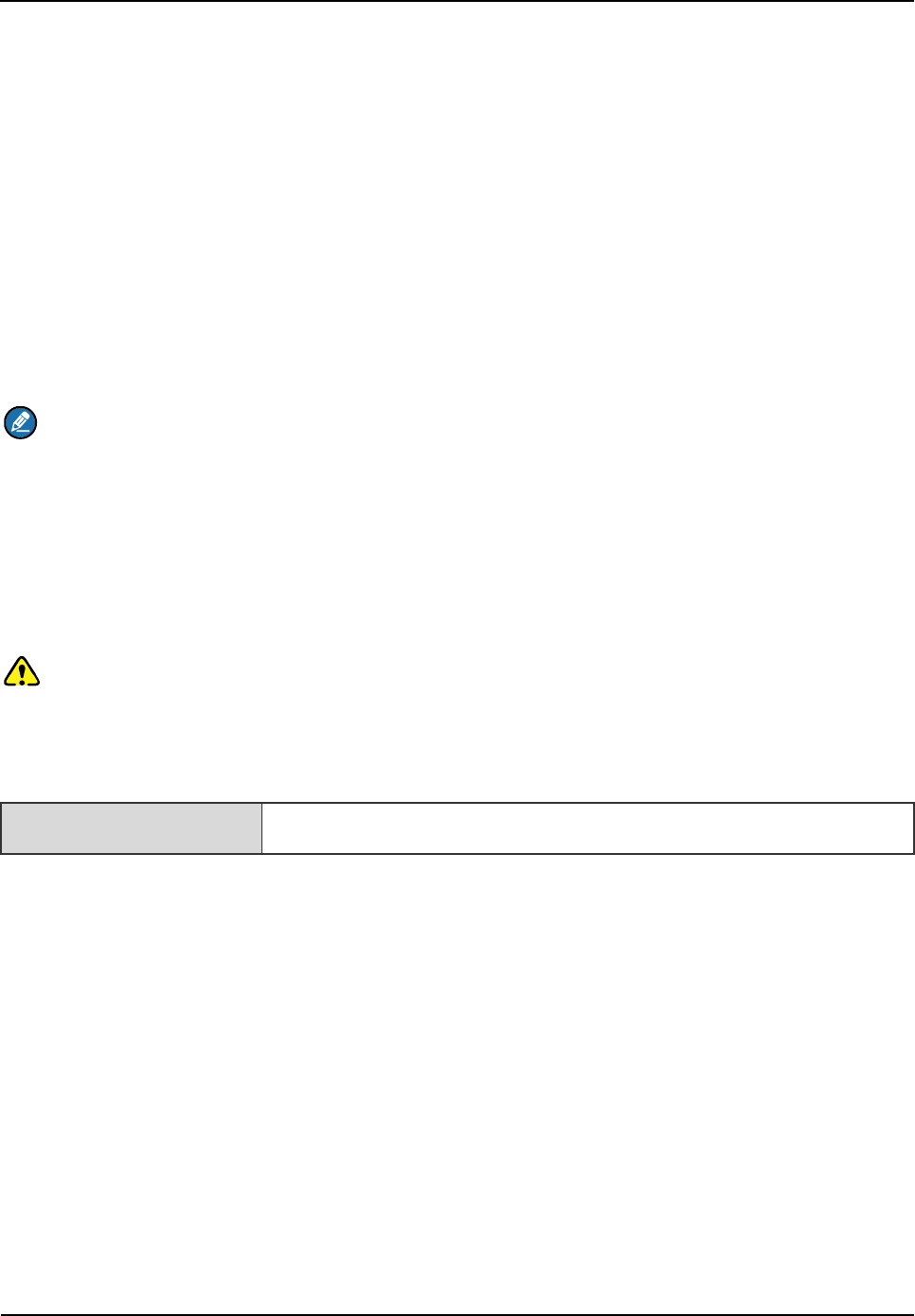
Step 3 Use a Claw hammer or a straight screwdriver to pry the tongue, as shown in Figure 3-2.
Tools Claw hammer and straight screwdriver
Installation
Owner's Manual
40
Figure 3-2 Removing the Cover
Step 4 Remove the cover. The wooden case may contain the carton or cabinet. As for the former,
directly take out the carton from the wooden case and unpack as instructed in 3.4.3Unpacking
Cartons. As for the latter, proceed to the next steps.
Caution
Pay attention to the nails on the bottom cover, to avoid bodily injuries.
Step 5 Using the same method, remove the box surrounding the plank.
Step 6 Remove the foam plate.
Step 7 Slide the cabinet out of the wooden case slowly.
3.4.3 Unpacking Cartons
Tool Paper knife
To open a carton, do as follows:
Step 1 Check the type and quantity of articles inside the carton according to labels, and cut the straps
along the seam of the carton cover by the paper knife.
Caution:
Use moderate force to avoid damaging the articles inside.
Step 2 Remove the foam plates and articles.
Owner's Manual
Installation
41
3.4.4 Inspections
After unpacking all wooden cases and cartons, carefully check the name, type, quantity of goods
against the Packing List, and then accept them.
3.5 Installing the Cabinet
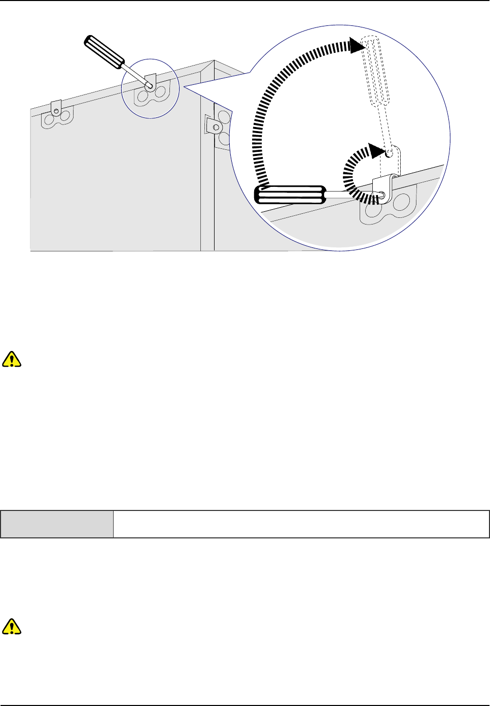
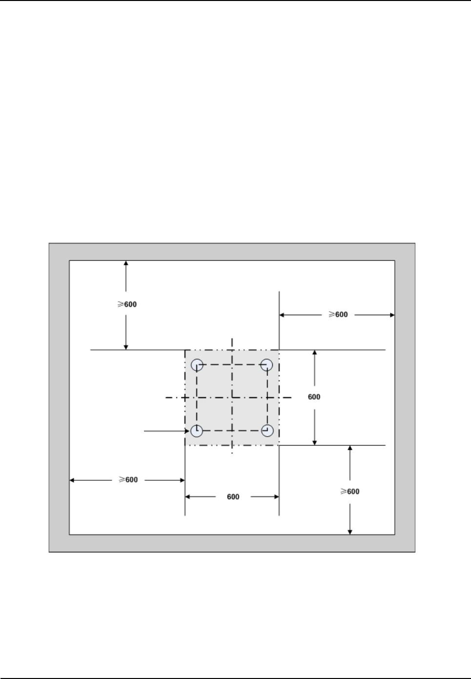
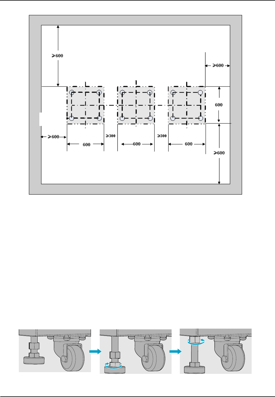
3.5.1 Determine the Installation Position
Determine the installation position of the cabinet according to the installation chart. The available
space for maintenance should be preserved and be no less than 600mm around the front and back
door, as shown in Figure 3-3 and Figure 3-4.
Figure 3-3 Layout of holes for a Single Cabinet
Wheel
Installation
Owner's Manual
42
Figure 3-4 Layout of holes for Combined Cabinet
3.5.2 Installing the Cabinet
To install the cabinet, do as follows:
Step 1 Place the cabinet in the planned position.
Fix the cabinet by tightening four bolts at the bottom of the cabinet, as shown in Figure 3-5.
1. Loosen the upper nut counter-clockwise by the spanner.
2. Loosen the lower nut counter-clockwise by the spanner and lift the cabinet to an appropriate
height.
3. Tighten the upper nut and screw clockwise.
Figure 3-5 Tightening the Bolt
Wheel
Owner's Manual
Installation
43
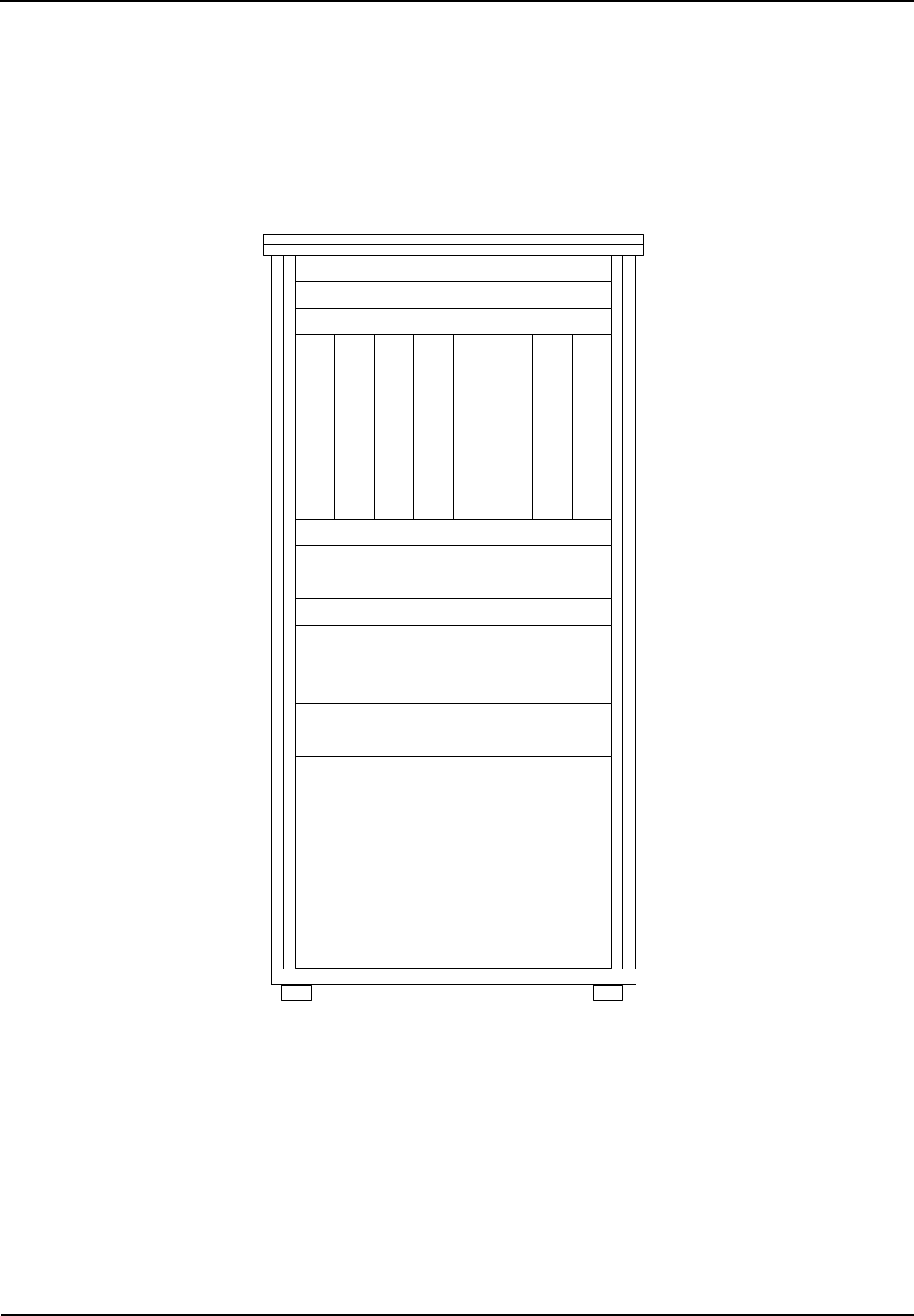
3.6 Installing Modules into the Cabinet
3.6.1 Module Layout
The position of all modules to be installed is shown in Figure 3-6.
c
Decorative Unit
Decorative Unit
Wiring Rack
C
H
U
C
H
U
C
H
U
C
H
U
B
S
C
U
B
S
C
U
P
S
U
P
S
U
Wiring Rack
FAN
Wiring Rack
DIU
Router/IP-E1
COM
Figure 3-6 of Module Layout
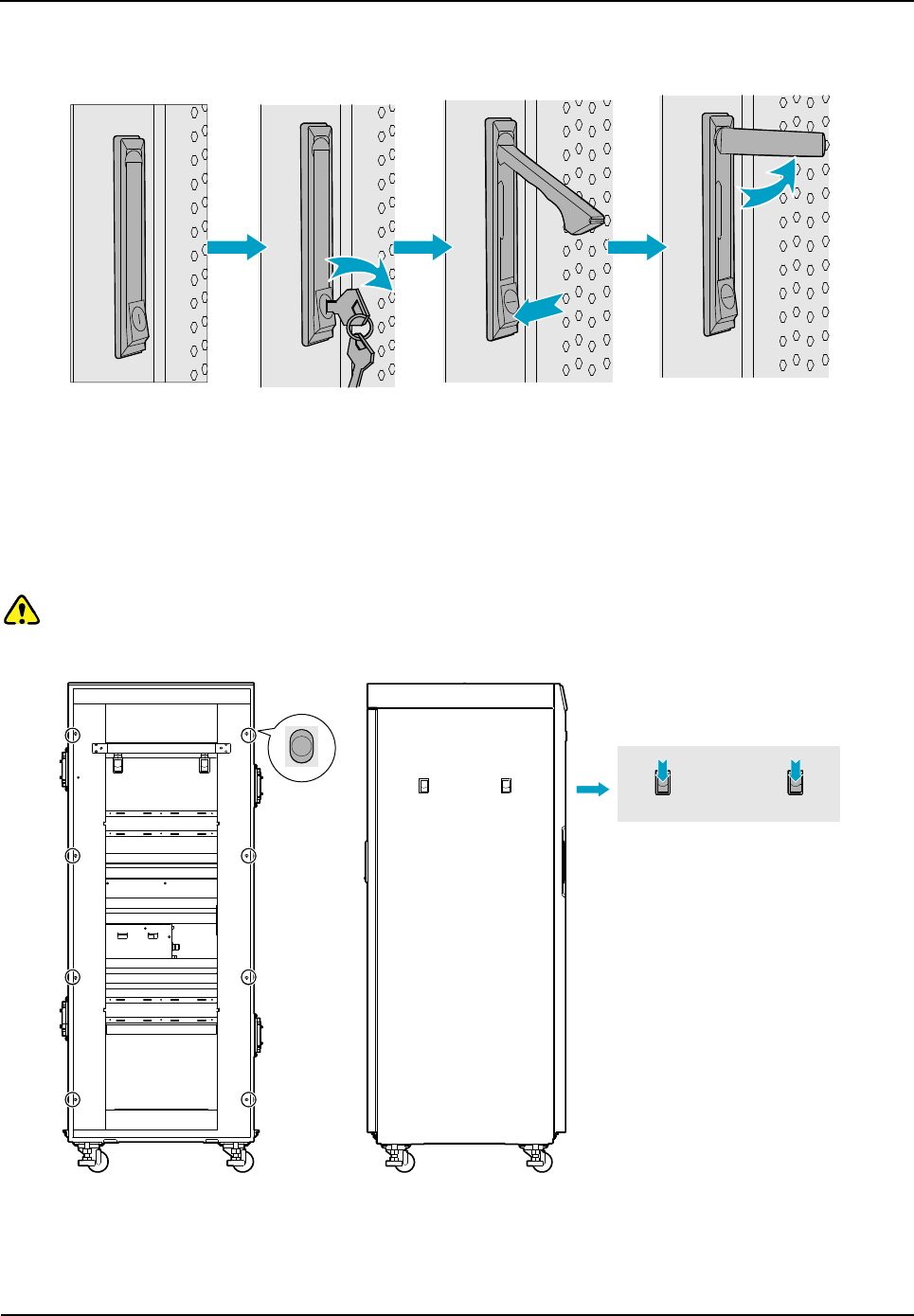
3.6.2 Installation Procedures
Step 1 Open the front and back door, as shown in Figure 3-7.
1. Unlock and remove the key in case of the keyhole in a horizontal position.
2. Firmly press PUSH until the door knob is bounced.
3. Turn the door knob to the right.
Installation
Owner's Manual
44
4. Pull the door knob outwards and open the cabinet door.
Figure 3-7 Opening the Cabinet Door
Step 2 Disassemble the side doors as shown in Figure 3-9.
1. Remove the eight screws on the frame.
2. Press down on the two latches and pull out the side door outwards.
Caution:
Care shall be taken to avoid injuries upon pulling out the side door outwards.
Figure 3-8 Disassembling the Side Door
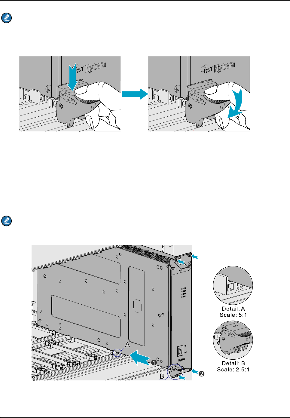
Step 3 Insert the modules into the cartridge (take the BSCU installation for example)
Owner's Manual
Installation
45
Note:
Make sure the power switch is set to OFF before installing the PSU.
1. Loosen the two ejectors as shown in Figure 3-9.
Figure 3-9 Loosening the Ejector
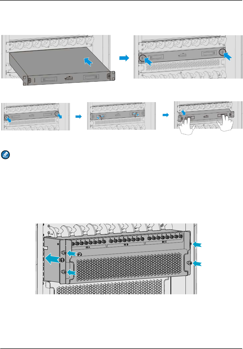
2. Slide the BSCU along the guide rails smoothly as shown in Figure 3-10(1).
3. Perform the step 1 in a reverse way to lock the two ejectors.
4. Tighten the two screws on the two ejectors and the board respectively as shown in Figure
3-10(2).
Note:
Loosen the two ejectors and draw out the module in case of removing it during installation.
Figure 3-10 Installing the BSCU
Step 4 Install the FAN as shown in Figure 3-11.
Installation
Owner's Manual
46
1. Slide the FAN along the guide rails smoothly until a click is heard.
2. Fasten the two screws on the ear of the FAN.
Figure 3-11 Installing the FAN
Figure 3-12 Removing the FAN
Note:
During installation, if you have to take out the FAN, please first unfasten the screws, and then
unlock the first panel, finally pull the FAN out. See Figure 3-12.
Step 5 Install the DIU as shown in Figure 3-13.
1. Slide the DIU along the guide rails.
2. Fasten all screws to fix the DIU.
Figure 3-13 Installing the Divider Unit
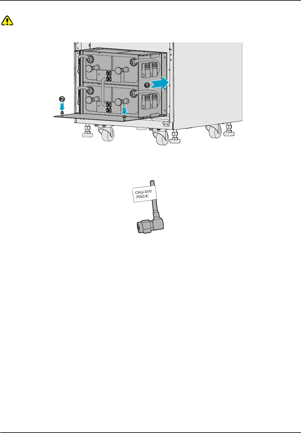
Step 6 Install the COM as shown in Figure 3-14.
1. Slide the COM along the guide rails.
2. Fasten the four screws.
Owner's Manual
Installation
47
Caution:
Handle with care as the COM is heavy.
Figure 3-14 Installing the Combiner Unit
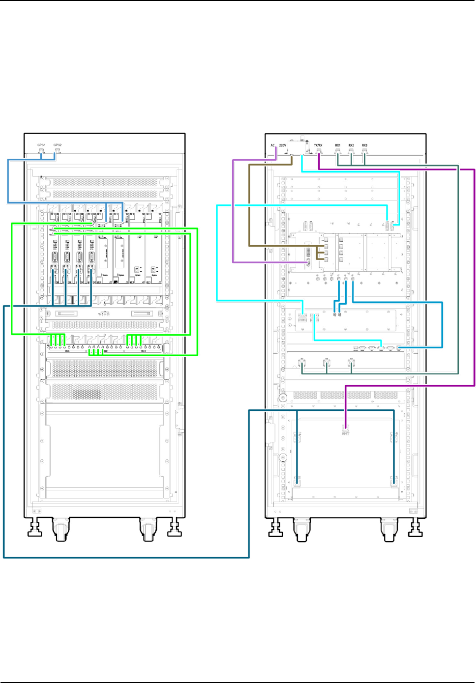
Step 7 Connect all cables as shown in Figure 3-16.
Figure 3-15 Cable Diagram
Step 8 Install the side doors.
1. Align the side door with the frame and firmly press the latch.
2. Fasten the eight screws.
3.7 Installing Cables
3.7.1 Equipment Status
The equipment shall be in the following status before connecting cables:
The cabinet has been installed.
All modules have been installed and the power switch is set to OFF.
3.7.2 Cables
Cables are described in Table 3-3 and their positions are shown in Figure 3-16. Installation positions
Installation
Owner's Manual
48
are located on top of the cabinet.
Name Color Remark
Base Station Ground
Cable (40m) Yellowish green
Lead, 16 mm2, 49-core, and 450/750V, outer diameter:
8.1
Subject to the actual needs.
AC Power Cord (15m) Black/white 3-core, 300/500V, 3*2.5 mm2,
Subject to the
investigating data on the site
RF Jumpers (3 pcs) Black 1/2 inch, N-Male to N-Male, 3Pcs
Table 3-3 Cables Description
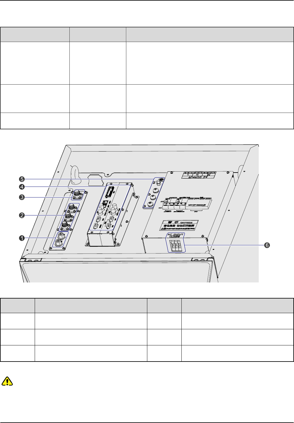
Figure 3-16 External Cable Connection
No. Name No. Name
1 GPS Antenna Interface 2 RX Interface
3 TX Interface 4 Communication Interface
5 Ground Interface 6 Power Inlet
Table 3-4 Descriptions on the interface of external cable connection
Note:
Install the power cable properly.
Do handle the ground cable gently to avoid possible looseness during installation.

Owner's Manual
Installation
49
The Disconnector is available for shortcut between the live line and null line only.
3.8 Examination after Installation
3.8.1 Equipment Status
The equipment shall be in the following status prior to hardware examination.
The cabinet has been installed.
All modules have been installed.
The external power has been installed and all cables have been connected.
All switches of the power distribution box are set to OFF.
3.8.2 Examining the Cabinet
The following requirements shall be met after installation.
No. Check Item
1 The position of the cabinet should conform to the design drawing.
2 All modules should be installed correctly.
3 All cables within the cabinet should be connected properly.
4 The side door should be installed and the grounding cables should be connected properly.
5
All screws should be tightened. Be sure to put flat washers and spring washers on all bolts
correctly.
6 The cabinet should be placed horizontally and orderly.
7 The surface of the cabinet should be clean and well painted. No dust and other sundries are
in the cabinet.
8 All labels should be correct, clear and not be missed.
9 The plastic dust cap on top of the cabinet should be installed properly.
Table 3-5 Checklist of Cabinet Installation
3.8.3 Examining Cables
The following requirements should be met after connection.
Installation
Owner's Manual
50
No. Check Item
1 All cables should not be damaged.
2 All cables are one-piece cables, without any joint in the middle.
3 Excess grounding cables should be cut off.
Table 3-6 Checklist of Cables
3.8.4 Power On and Examination
Caution:
First measure the resistance of all power connectors and ground connectors using the multimeter
and check whether short circuit occurs.
The procedures are described as follows:
Step 1 Check the input voltage (220V) from the main power and whether the live line and null line
connect correctly.
Step 2 The switch of the Disconnector in the BSIU is set to ON.
Step 3 All switches of the PSU are set to ON.
Step 4 Check whether all modules are powered properly.
Name Normal Power Indication
CHU The PWR indicator on the front panel glows and the ALM indicator goes out.
BSCU The PWR indicator on the front panel glows and the ALM indicator goes out.
PSU The PWR indicator on the front panel glows and the ALM indicator goes out.
FAN The PWR indicator on the front panel glows.
Table 3-7 Checklist of Power Situation
Note:
If the LED on the front panel does not work correctly, please re-power it on or re-insert the module
after disconnecting power. If it doesn’t solve the problem, please contact us.
3.8.5 Environment Examination
The following table lists the check item of environment on site.

Owner's Manual
Installation
51
No. Check Item
1 The equipment room should be clean and tidy.
2
No sundries should be placed in the grooves, at the bottom of the cabinet or around the
cabinet.
3 The floor in the equipment room should be free from sundries.
Table 3-8 Checklist of Environment on Site

Basic Operations
Owner's Manual
52
4. Basic Operations
4.1 Powering on
Step 1 The external power supply is connected.
Step 2 The switch of the Disconnector is set to ON.
Step 3 All switches of the PSU are set to ON.
4.2 Powering off
Step 1 All switches of the PSU are set to OFF.
Step 2 The switch of the Disconnector is set to OFF.
Step 3 Disconnect the external power supply.

Owner's Manual
Troubleshooting
53
5. Troubleshooting
Phenomena Solution
The PWR LED does not light up. Check the power supply.
The ALM LED on the PSU glows red. Disconnect the power and replace the PSU.
The ALM LED on the CHU glows red. Replace the CHU.
The ALM LED on the BSCU glows red. Replace the BSCU.
Table 5-1 Troubleshooting

Routine Maintenance
Owner's Manual
54
6. Routine Maintenance
6.1 Purpose
Routine maintenance is to ensure stable and reliable operation of the equipment. It can help to know
the operation status of the equipment, so as to detect the potential troubles and remove them on time.
The routine maintenance should achieve the following objects:
Remove all potential troubles to keep the system work properly.
Ensure all performance and service specifications meet requirements.
Ensure good collaboration with the entire network.
Make sure that new equipment or the extended equipment accesses to the network properly.
6.2 Tasks
Clean the equipment room regularly.
Check the working status of the base station regularly. If the abnormal situation occurs, deal with it in
time.
Clean up the dust regularly.

Owner's Manual
Routine Maintenance
55
A Abbreviations
Abbr. Full Name
AGC Auto Gain Control
BSCU Base Station Controller Unit
BSCU-MB Base Station Controller Unit Main Board
BSS Base Station Sub-system
CAN Controller Area Network
CC Call Control
CCL Call Control Layer
CHB Channel Board
CHU Channel Unit
COM Combiner
CPCI Compact Peripheral Component Interconnect
DIU Divider Unit
DLL Data Link Layer
EC Extended Chassis
EIB Extended Interface Board
ETSI European Telecommunications Standards Institute
FAN Fan Unit
GPI General Purpose Input
GPIO General Purpose Input Output
GPO General Purpose Output
GPS Global Positioning System
GPSB GPS Clock Board

Routine Maintenance
Owner's Manual
56
Abbr. Full Name
ICB Interconnect Backboard
IO Input and Output
IRU Interconnect Relay Unit
LLC Logical Link Control
LNA Low Noise Amplifier
MAC Media Access Control
MC Main Chassis
MCB Main Control Board
MM Mobile Management
MPSC Machine-Frame Power Support Component
MPU Micro Processor Unit
PAB Power Amplifier Board
PCI Peripheral Component Interconnect
PICMG PCI Industrial Computer Manufacture's Group
PDT Professional Digital Trunking
PSB Package Switch Board
PSU Power Support Unit
RFDS Radio Frequency Distributing System
RT Router
RXB Receive Board
TDM Time Division Multiplex
TMA Tower Mounted Amplifier
TSCU Trunking Station Control Unit
EXB Excitation Board

Owner's Manual
Routine Maintenance
57
Abbr. Full Name
VGA Video Graphics Array

exposure limits set forth for an controlled
FCC Warning:
Any Changes or modifications not expressly approved by the party responsible for compliance could
void the user's authority to operate the equipment.
This device complies with part 15 of the FCC Rules. Operation is subject to the following two
conditions: (1) This device may not cause harmful interference, and (2) this device must accept any
interference received, including interference that may cause undesired operation.
This equipment complies with FCC radiation
environment .This equipment should be installed and operated with minimum distance 2.5 m
between the radiator& your body.
Industry Canada
This device complies with Industry Canada licence-exempt RSS standard (s).
Operation is subject to the following two conditions: (1) this device may not cause
interference, and (2) this device must accept any interference, including interference
that may cause undesired operation of the device.
The term “IC:” before the certification/registration number only signifies that the
Industry Canada technical specifications were met.
Under Industry Canada regulations, this radio transmitter may only operate using an
antenna of a type and maximum (or lesser) gain approved for the transmitter by
Industry Canada. To reduce potential radio interference to other users, the antenna
type and its gain should be so chosen that, the equivalent isotropically radiated power
(e.i.r.p.) is not more than that necessary for successful communication.
Le présent appareil est conforme aux CNR d'Industrie Canada applicables aux appareils radio exempts de
licence.
L'exploitation est autorisée aux deux conditions suivantes:
(1) l'appareil ne doit pas produire de brouillage, et
(2) l'utilisateur de l'appareil doit accepter tout brouillage radioélectrique subi, même si le brouillage est
susceptible d'en compromettre le fonctionnement.
Conformément à la réglementation d'Industrie Canada, le présent émetteur radio peut fonctionner avec une
antenne d'un type et d'un gain maximal (ou inférieur) approuvé pour l'émetteur par Industrie Canada. Dans
le but de réduire les risques de brouillage radioélectrique à l'intention des autres utilisateurs, il faut choisir
le type d'antenne et son gain de sorte que la puissance isotrope rayonnée équivalente (p.i.r.e.) ne dépasse
pas l'intensité nécessaire à l'établissement d'une communication satisfaisante.
Owner's Manual Routine Maintenance
58

controlled environment. This transmitter must not be co-located or operating in
This product meets the applicable Industry Canada technical specifications.
This Class A digital apparatus complies with Canadian ICES-003.
IC Radiation Exposure Statement:
This equipment complies with IC RF radiation exposure limits set forth for an
conjunction with any other antenna or transmitter.
This equipment should be installed and operated with minimum distance 2.5m
between the radiator & your body.
Le present matériel est conforme aux specifications techniques applicables d’Industrie Canada.
Owner's Manual Routine Maintenance
59