Hytera Communications PD75XIU1 Digital Portable Radio User Manual
Hytera Communications Corporation Limited Digital Portable Radio
User manual
811PD75000000
C10524 L06774
2014
Hytera Communications Corporation Limited.
Hytera Communications Corporation Limited.
DIGITAL PORTABLE RADIO
OWNER’S MANUAL

Preface
Thanks for your favor in our product. This manual is helpful for you to quickly know how to use the
product. For detailed features and operations, please refer to the Feature Book along with the product.
This manual is applicable to the following product:
PD75Xi Digital Portable Radio

Instructional Icons
: Indicates functions that are available on digital
channel only.
: Indicates functions that are available on analog
channel only.
Functions marked with neither the above icons are
available on both analog and digital channels.
Disclaimer
Hytera Communications Corporation Limited (the
Company) endeavors to achieve the accuracy and
completeness of this manual, but no warranty of
accuracy or reliability is given. All the specifications
and designs are subject to change without notice due
to continuous technology development. No part of
this manual may be copied, modified, translated, or
distributed in any manner without the express written
permission of us.
We do not guarantee, for any particular purpose, the
accuracy, validity, timeliness, legitimacy or completeness
of the Third Party products and contents involved in this
manual.
If you have any suggestions or would like to learn more
details, please visit our website at: http://www.hytera.
com.
RF Radiation Information
This product must be restricted to operations in an
occupational/controlled RF exposure environment.Users
must be fully aware of the hazards of the exposure and
able to exercise control over their RF exposure to qualify
for the higher exposure limits.
Radio Frequency (RF) is a frequency of electromagnetic
radiation in the range at which radio signals are
transmitted. RF technology is widely used in
communication, medicine, food processing and other
RF Radiation Safety
In order to ensure user health, experts from relevant
industries including science, engineering, medicine and
health work with international organizations to develop
standards for safe exposure to RF radiation. These
standards consist of:
United States Federal Communications Commission,
Code of Federal Regulations; 47CFR part 2 sub-part J;
American National Standards Institute (ANSI)/Institute
of Electrical and Electronic Engineers (IEEE) C95.
1-1992;
Institute of Electrical and Electronic Engineers (IEEE)
C95.1-1999;
International Commission on Non-Ionizing Radiation
Protection (ICNIRP) 1998.
FCC Regulations
Federal Communication Commission (FCC) requires
that all radio communication products should meet the
requirements set forth in the above standards before
they can be marketed in the U.S, and the manufacturer
shall post a RF label on the product to inform users
of operational instructions, so as to enhance their
occupational health against exposure to RF energy.
Operational Instructions and Training
Guidelines
To ensure optimal performance and compliance with
the occupational/controlled environment RF energy
exposure limits in the above standards and guidelines,
users should transmit not more than 50% of the time and
always adhere to the following procedures:
RF energy will be generated only when the radio is
transmitting.
The radio must be 2.5 centimeters away from human
body when transmitting.
FCC Statement
This equipment has been tested and found to comply with the
limits for a Class B digital device, pursuant to part 15 of FCC
Rules. These limits are designed to provide reasonable
protection against harmful interference in a residential
installation. This equipment generates and can radiate radio
frequency energy. If not installed and used in accordance with
the instructions, it may cause harmful interference to radio
communications. However, there is no guarantee that
interference will not occur in a particular installation.
Verification of harmful interference by this equipment to
radio or television reception can be determined by turning it
off and then on. The user is encouraged to try to correct the
interference by one or more of the following measures:
zReorient or relocate the receiving antenna. Increase the
separation between the equipment and receiver.
zConnect the equipment into an outlet on a different
circuit to that of the receiver's outlet.
zConsult the dealer or an experienced radio/TV technician
for help.
Operation is subject to the following two conditions:
zThis device may not cause harmful interference.
zThis device must accept any interference received,
including interference that may cause undesired
operation.
Note: Changes or modifications to this unit not expressly
approved by the party responsible for compliance could void
the user's authority to operate the equipment.
RF Exposure Compliance and
Control Guidelines and Operating
Instructions
To control your exposure and ensure compliance with the
occupational/controlled environmental exposure limits,
always adhere to the following procedures.
Guidelines:
zDo not remove the RF Exposure Label from the device.
zUser awareness instructions should accompany device
when transferred to other users.
zDo not use this device if the operational requirements
described herein are not met.
Operating Instructions:
zTransmit no more than the rated duty factor of 50% of the
time. To transmit (talk), push the Push-To-Talk (PTT)
key. To receive calls, release the PTT key. Transmitting
50% of the time, or less, is important because the radio
generates measurable RF energy only when transmitting
(in terms of measuring for standards compliance).
zKeep the radio unit at least 2.5 cm away from the face.
Keeping the radio at the proper distance is important as
RF exposure decreases with distance from the antenna.
The antenna should be kept away from the face and eyes.
zWhen worn on the body, always place the radio in a
Hytera-approved holder, holster, case, or body harness or
by use of the correct clip for this product. Use of
non-approved accessories may result in exposure levels
which exceed the FCC's occupational/controlled
environmental RF exposure limits.
zUse of non-approved antennas, batteries, and accessories
causes the radio to exceed the FCC RF exposure
guidelines.
zContact your local dealer for the optional accessories of
the product.
EU Regulatory Conformance
compliance with the essential requirements and other
relevant provisions of the Directive 2014/53/EU.
Please note that the above information is applicable to
EU countries only.
1
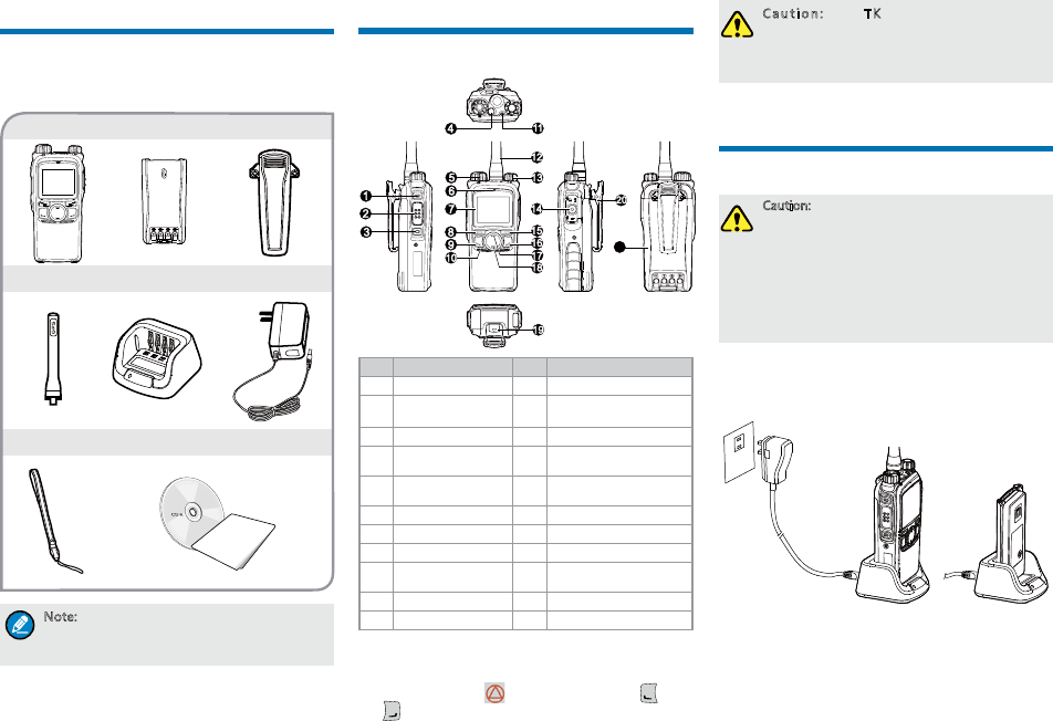
Items in the Package
Please unpack carefully and check that all items listed
below are received. If any item is missing or damaged,
please contact your dealer.
4UZK :NK LXKW[KTI_HGTJOY SGXQKJUTZNK
RGHKRULGTZKTTG!OLTUZVRKGYKXKLKXZUZNKRGHKR
UTZNKXGJOULUXLXKW[KTI_HGTJOTLUXSGZOUT
Antenna Charger Power Adapter
Radio Unit Battery Belt Clip
Strap Documentation Kit
Product Overview
Product Control
No. Part Name No. Part Name
1 SK1 (Side Key 1) 12 Antenna
2PTT (Push-to-
Talk) Key 13 Power On-Off/Volume
Control Knob
3 SK2 (Side Key 2) 14 Accessory connector
4 TK (Top Key) 15 Back/Group Call
Management Key
5Group Call
Selector knob 16 BackDial/End/Home
Screen Key
6 Microphone 17 Up Key
7 LCD Display 18 Down Key
8 OK/Menu Key 19 Battery Latch
9Answer/Redial/
Call Key 20 Belt Clip
10 Speaker 21 Battery
11 LED Indicator - -
Programmable Keys
For enhanced convenience, you may request your dealer
to program the TK ( ), SK1, SK2 and P1( ) and
P2( ) as shortcuts to certain functions. Please refer to
the corresponding Feature Book for more details.
)G[ZOUT :NK:1OYVXUMXGSSKJ]OZN
KSKXMKTI_LKGZ[XKH_JKLG[RZYNUXZVXKYY
+SKXMKTI_5T!RUTMVXKYY +SKXMKTI_5LL/Z
OYVXUMXGSSGHRKH__U[XJKGRKX
Before Use
Charging the Battery
)G[ZOUT
3GQKY[XKZNKXGJOUOY VU]KXKJULLHKLUXK
INGXMOTM8KGJZNK9GLKZ_ /TLUXSGZOUT
(UUQRKZOTGJ\GTIKZUMKZTKIKYYGX_YGLKZ_
OTLUXSGZOUT
:UGINOK\KUVZOSGRHGZZKX_VKXLUXSGTIK
VRKGYKINGXMKZNKHGZZKX_LUXGZRKGYZ
NU[XYHKLUXKOTOZOGR[YK
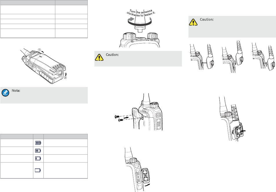
Please use the charger specified by the Company to
charge the battery. Charging Diagram is listed below.
Charging Status Indication (on charger):
OWNER'S MANUAL
21
)NGXMKZNK8GJOU
]OZNHGZZKX_GZZGINKJ
)NGXMKZNK(GZZKX_
2
Ĝhh
LED Indication Charging Status
The LED Indicator flashes red
slowly. Standby (no load)
The LED Indicator glows red. Charging
The LED Indicator glows orange. 90% charged
The LED Indicator glows green. Fully charged
The LED Indicator flashes red
rapidly. Charging failed
Attaching the Battery
4UZK :UXKSU\KZNKHGZZKX_Z[XTULLZNKXGJOU
LOXYZ:NKTYROJK ZNKHGZZKX_ RGZIN[V]GXJYZU
[TRUIQZNKHGZZKX_GTJXKSU\KOZ
Checking the Battery Power
You may check the current battery power by holding
down the programmed Battery Power Indicator key
preset by your dealer. And release the key to exit. Battery
power indications are listed below:
LED Indication Icon Battery Power
The LED Indicator
glows green. High
The LED Indicator
glows orange. Medium
The LED Indicator
glows red. Low
The LED Indicator
glows red and low
battery alert beeps.
Under the low battery
threshold. Please recharge
or replace the battery for
proper radio operation
Attaching the Antenna
)G[ZOUT *UTUZNURJZNKXGJOUH_OZYGTZKTTG
UZNKX]OYKZNKVKXLUXSGTIKGTJROLKYVGTULZNK
GTZKTTG]ORRHKXKJ[IKJ
Attaching the Belt Clip
1. Loosen the screws from the back of the radio.
2. Align the screw holes of the belt clip with those on the
radio’s back, and then tighten the screws.
Attaching the Accessories
1. Open the accessory connector cover as shown below.
2. Align the accessory (such as an audio accessory,
or a programming cable) plug with the accessory
connector.
)G[ZOUT *UTUZYIXGVKZNKYOROIUTKX[HHKX
Y[XXU[TJOTMZNKGIIKYYUX_IUTTKIZUXYIXK]
NURKOTUXJKXZUKTY[XKZNK]GZKXVXUUL
VKXLUXSGTIKULZNKXGJOU
3. Tighten the screw on the accessory plug.
"Click"
3
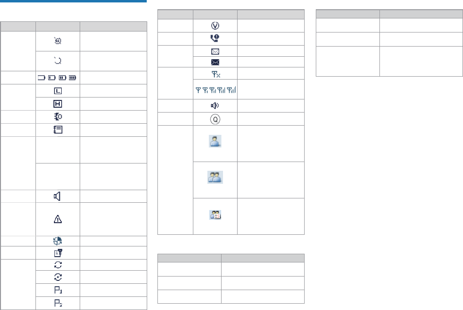
Status Indication
LCD Icon
Name Icon Radio Status
GPS Icon
The GPS feature is
enabled, and valid GPS
data is received.
The GPS feature is
enabled, but no valid
GPS data is received.
Battery
Power Icon
More bars indicate more
battery power.
TX Power
Icon
Low TX power for the
current channel.
High TX power for the
current channel.
Accessory
Icon
An accessory is
connected.
Work Order
Icon
One or more new work
orders are received.
Operation
Mode Icon
DM
Direct Mode: Under
this mode, the radio
communicates with other
radios directly.
RM
Repeater Mode: Under
this mode, the radio
communicates with other
radios via a repeater.
Monitor Icon The Monitor feature is
enabled.
Emergency
Icon
The Emergency
mode (except secret
emergency) is activated
or an emergency alarm
is received.
Roam Icon The radio is roaming.
Scrambler/
Encrypt Icon
The Scrambler/Encrypt
feature is enabled.
Scan Icon
The radio is scanning.
Scanning stays on a
non-priority channel.
Scanning stays on
Priority Channel 1.
Scanning stays on
Priority Channel 2.
Name Icon Radio Status
VOX Icon The VOX feature is
enabled.
Missed Call
Icon Missed call(s).
Message
Icon
Unread message(s)
Inbox is full.
RSSI Icon
No signal.
More bars indicate better
signal strength.
Speaker
Icon The speaker is unmuted.
LQO Icon The LQO feature is
enabled.
Call/Contact
Icon
Indicates Private Call
during a call.
Indicates Private
Contact in the contact
list.
Indicates Group Call
during a call.
Indicates Group
Contact in the contact
list.
Indicates All Call
during a call.
Indicates All Call
Contact in the contact
list.
LED Indicator
LED Indication Radio Status
The LED indicator
Powering on
The LED indicator
glows green. Receiving
The LED indicator
glows red. Transmitting
LED Indication Radio Status
The LED indicator
Scanning or Roaming
The LED indicator
Emergency
The LED indicator
glows orange.
Call hung. During a call, you
can hold down the PTT key to
talk to the other party before
the call hang time expires.
4
Basic Operation
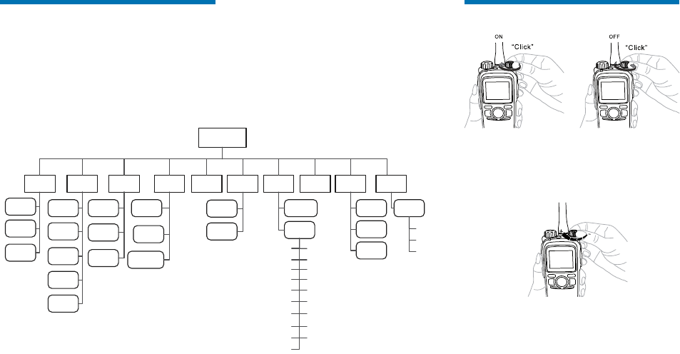
Powering On/Off
Adjusting the Volume
You can adjust the volume of output voice, alert tone and
Volume Control
Knob
the dealer.
Selecting a Zone
A zone is a group of channels exhibiting the same
property, which is programmed by your dealer and can
facilitate convenient management over the channels. The
radio supports up to 64 zones, each with a maximum of
16 channels. You may select a zone through any of the
following methods:
Via the menu: Go to “Menu -> Zone”, press the Up/
Down key to select an appropriate zone, and then
press the OK key to switch to the selected zone.
Via Programmable Keys: You can toggle to the
appropriate zone by pressing the programmed Zone
Up or Zone Down key preset by your dealer.
Menu Navigation
The following diagram outlines the menu structure of the radio. You can personalize menu option displayed in the
radio via your dealer.
!Menu key to enter the main menu, and then press the
Up/Down#OK key. This manual only describes the paths to the
menus in terms of menu operations, for example, to access the contact list, go to “Contact -> Contact List”.
!$$$
&
disable the feature.
Menu
Contact Message Call Logs Settings Zone Accessori
es
Phone
Contact
List
New
Contact New Msg
Quick Text
Outbox
Drafts
Inbox
Outgoing
Incoming
Phone List
Missed
Manual
Dial
Keypad Lock
DTMF
Keypad
Roam
Power Level
Radio
Settings
Backlight
Device
Information
Brightness
Language
Encrypt
Tones
LED
Rent
LQO
VOX
Lone Worker
Priority
Covert Mode
Man Down
GPS
Scan List
Scan
Manual
Dial
Scan
On/Off
Scrambler
Vibration
Radio Password
Select Button Lock
Programm
ing
Frequency
Slot
Color
Code
Time Zone
GPS
On/Off
Position
View
5
Selecting a Channel
If the Channel Notify feature is enabled, you will hear the
corresponding channel number when switching to any
channel.
Managing the Contacts
You can have management of your contacts via the
menu “Contact -> Contact List” in the radio. The contact
list saves the information of private call, group call and
all call contacts. You can access the “Contact List” menu
via the “Contact” menu or by pressing the programmed
Contact List key.
You can view contact details, edit or delete the private
call contact in the “Contact List” menu. You can send to
a private call contact the following commands: Alert Call,
Radio Check, Remote Monitor, Radio Enable or Radio
Disable. Please refer to Feature Book for details.
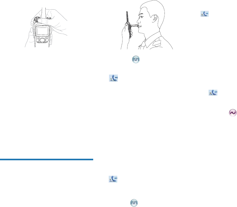
Call Services
After the radio is powered on, you can make and
receive calls. To ensure optimal volume of the receiving
radio, hold the palm microphone approximately 2.5 to 5
centimeters away from your mouth.
Private Call
Initiating a Private Call
When initiating a private call, the radio will display the
icon . You can make a private call through the
following ways:
Preset Contact
In the home screen, hold down the PTT key on the palm
microphone to initiate a Private Call to the Private Call
contact preset for the current channel.
You may request your dealer to preset a regular Private
Call contact, Group Call contact or an All Call contact for
each digital channel.
Contact List or Call Logs
1. Go to “Menu -> Contact” or “Menu -> Call Logs” and
access the “Contact List” submenu.
2. Use the Up/Down key to select the private call
contact you want to call.
3. Hold down the PTT key to initiate a Private Call.
Receiving and Responding to a Private Call
After receiving a private call, the radio will display the
icon , then you can listen without any operation.
You can hold down the PTT key to call back within the
preset time. If you do not respond to it, the radio will
provide appropriate indications.
Group Call
Initiating a Group Call
When initiating a group call, the radio will display the icon
. You can make a group call through the following
ways. The operation is similar to initiating a private call.
Preset Contact
In the home screen, hold down the PTT key on the palm
microphone to initiate a Group Call to the Group Call
contact preset for the current channel.
Contact List
1. Go to “Menu -> Contact -> Contact List”.
2. Use the Up/Down key to select the group call contact
you want to call.
3. Hold down the PTT key to initiate a Group Call.
Receiving and Responding to a Group Call
After receiving a group call, the radio will display the
icon . You can hold down the PTT key to call back
within the preset time.
Call on Analog Channel (No
Signaling)
On an analog channel, you can hold down the PTT key
and talk to the microphone to transmit, and release the
PTT key to receive.
Please refer to the corresponding Feature Book for
operation description on how to make and receive calls
on the analog channel with signaling.
Emergency Call
In case of an emergency, you can use this feature to
ask for help from your companion or the control center.
The Emergency Call has the highest priority which can
terminate the ongoing calls with lower priorities on the
current channel. You can make an emergency call even
when your radio is transmitting or receiving.
!$
dealer. Please refer to the corresponding Feature Book
for details.
d)3
6
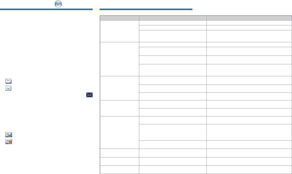
Message Services
This feature enables you to directly send a quick text
message and to forward the messages in the Inbox,
Outbox and Drafts.
Quick Text
The radio supports quick text message preset by your
dealer. You can directly send the message or edit it prior
to sending.
Inbox
The radio saves the received messages into the Inbox
and marks every message with a corresponding icon to
indicate its status.
: Read message
: Unread message
When the Inbox is full, the radio will display the icon
, and the earliest message will be overwritten by the
latest one automatically.
Outbox
The radio saves the sent messages into the Outbox
and marks every message with a corresponding icon to
indicate its status.
: The message is sent successfully.
: The message is not sent successfully. In this
case, you can resend it.
When the Outbox is full, the earliest message will be
overwritten by the latest one automatically.
Troubleshooting
Phenomena Analysis Solution
The radio fails to power
on.
The battery may be improperly installed. Remove the battery and then reattach it.
The battery power may be used up. Recharge or replace the battery.
The battery may be poorly connected due
to dirtied or damaged battery contacts.
Clean the battery contacts. If the problem cannot
be solved, contact your dealer or authorized service
center for inspection and repair.
During receiving,
the voice is weak,
discontinuous or totally
inactive.
The battery voltage may be low. Recharge or replace the battery.
The volume level may be low. Increase the volume by rotating the Volume Control
Knob.
The antenna may be loosened or
improperly installed. Reattach the antenna after turning off the radio.
The speaker may be blocked or
damaged.
Clean the surface of the speaker. If the problem
cannot be solved, contact your dealer or authorized
service center for inspection and repair.
You cannot
communicate with other
members.
The frequency or signaling may not
match that of other members.
Set your TX/RX frequency and signaling to the same
as that of other members.
The channel type (digital/analog) may be
set inconsistently.
Make sure all members are on the same digital/
analog channel.
You may be too far away from the group
members. Move towards other members.
Irrelevant
communication or
noise is heard on the
channel.
You may be interrupted by radios using
the same frequency. Change the frequency, or adjust the squelch level.
The radio may be set with no signaling. Set signaling for all member radios to avoid
interference at the same frequency.
The noise is too loud.
You may be too far away from other
members. Move towards other members.
You may locate in an unfavorable position.
For example, your communication may
be blocked by high buildings or frustrated
in the underground areas.
*
to try again.
You may suffer from external disturbance
(such as electromagnetic interference).
Stay away from equipment that may cause
interference.
GPS positioning fails. GPS signals may not be received due to
unfavorable position. *
You cannot use the
keys.
The keypad may fail to function
temporarily. Restart the radio.
The LCD does not
display any information. The LCD may fail to function temporarily. Restart the radio.
$+
dealer for more technical support.
7
Care and Cleaning
To guarantee optimal performance as well as a long
service life of the product, please follow the tips below.
Product Care
Do not pierce or scrape the product.
Keep the product far away from substances that can
corrode the circuit.
Do not hold the product by its antenna or earpiece
cable directly.
Attach the accessory connector cover when the
accessory is not in use.
Product Cleaning
)G[ZOUT :[XTULLZNKVXUJ[IZGTJXKSU\KZNK
HGZZKX_HKLUXKIRKGTOTM
<
surface and charging piece with a clean and dry lint-
free cloth or a brush regularly.
Use a non-woven cloth with neutral cleanser to clean
the device after long-time use. Do not use chemical
preparations such as stain removers, alcohol, sprays
or oil preparations, so as to avoid potential damage
on the surface.
Make sure the product is completely dry before use.
Optional Accessories
The following items are the main optional accessories
for the radio. For more information of other accessories,
please consult your local dealer.
)G[ZOUT ;YKZNKGIIKYYUXOKYYVKIOLOKJH_ZNK
)USVGT_UTR_/LTUZZNK )USVGT_YNGRRTUZ
HKROGHRKLUXGT_RUYYUXJGSGMKGXOYOTMU[ZUL
[YKUL[TG[ZNUXO`KJGIIKYYUXOKY
Power Supply: CHV09 Vehicle Adapter for Charger,
MCA05 Battery Optimizing System, MCA06 MCU
Multi-unit Rapid-rate Charger
Audio: EAN17 3-wire Surveillance Earpiece with
Transparent Acoustic Tube(Beige), EAN18 3-wire
Surveillance Earpiece with Transparent Acoustic
Tube(Black), EHN16 C-Earset, EHN17 Swivel Earset,
ESN12 Earbud, EAN23 Detachable Earpiece with
Transparent Acoustic Tube, ESW01-N1 Wireless
Earset Kit, SM18N2 Waterproof Remote Speaker
Microphone(IP57)
Cable: PC38 Programming Cable (USB Port)
Carrying Accessory: LCBN13 Universal Chest
Pack (Nylon)(Black); LCY003 Carrying Case (Thick
Battery)(Leather)(Swivel), LCY006 Carrying Case
(Thick Battery)(Leather)(Swivel)