Hytera Communications PT580HPF4 TETRA TERMINAL with Bluetooth and GPS User Manual
Hytera Communications Corporation Ltd. TETRA TERMINAL with Bluetooth and GPS
UserManual.wiki
>
Hytera Communications
>
PT580HPF4 User Manual
User Manual
Navigation menu
Upload a User Manual
Namespaces
Wiki Guide
HTML
PDF
Info
Views
User Manual
Discussion / Help
Navigation
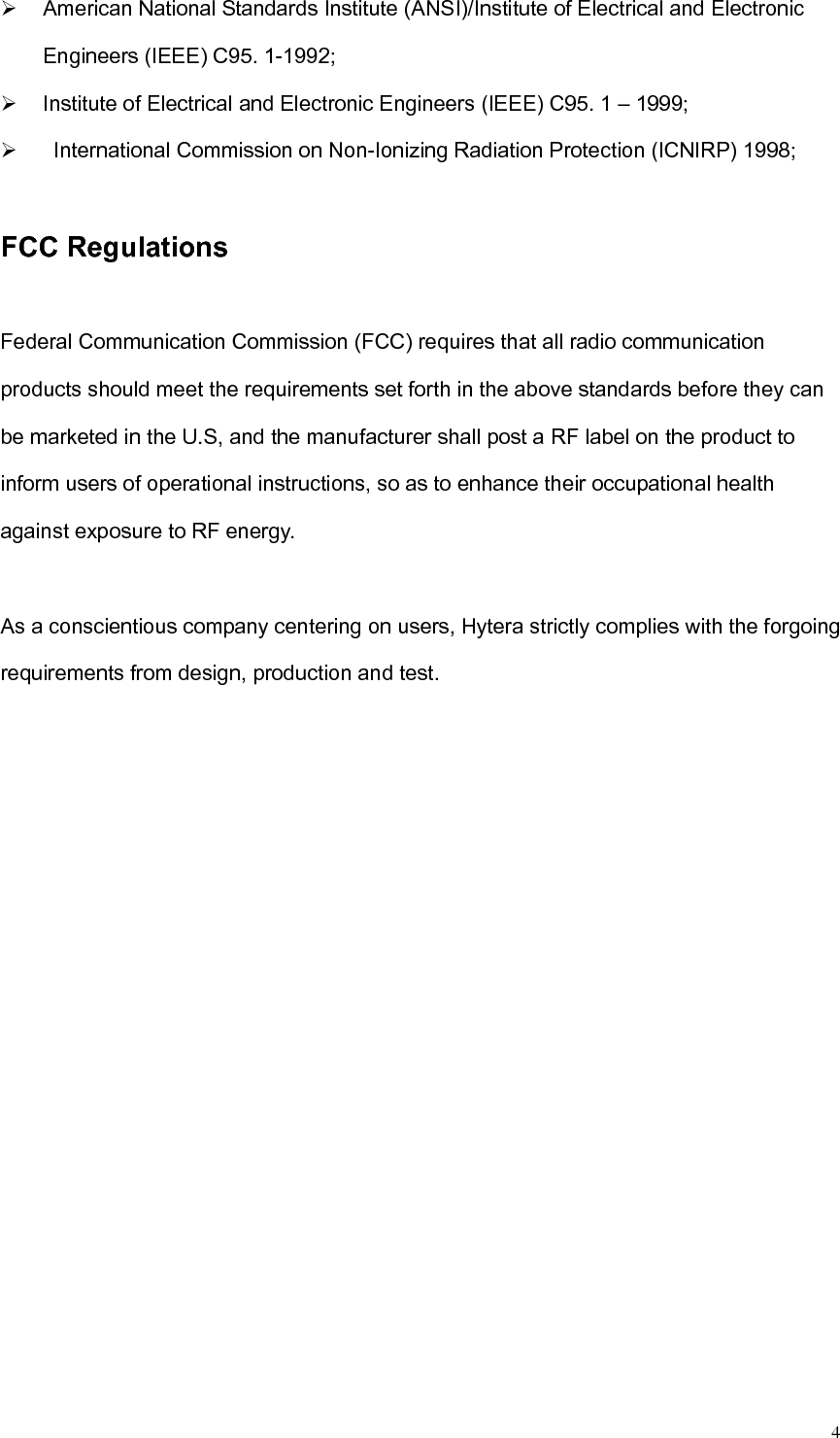

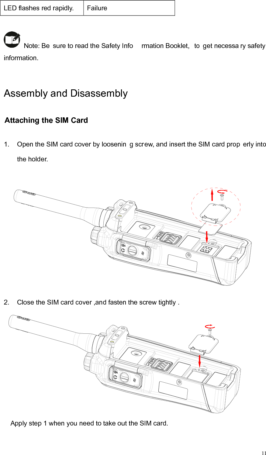
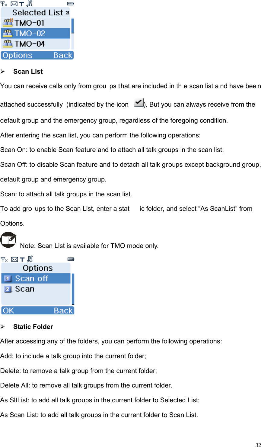
![18completed, the keypad will return to be locked. Switching Operation Mode You may switch the terminal betw een TM O a nd DMO thr ough any of the followin g methods: 1. Menu selection Press the Options key to access the menu, and then select TMO or DMO. Talk Group[Options]DMO OptionsTMOLanguageTalk GroupTMO OptionsDMOLanguageGPSGPS 2. Function key press In the home screen, press the Select Mode key to switch between TMO and DMO.](https://usermanual.wiki/Hytera-Communications/PT580HPF4/User-Guide-2860401-Page-20.png)

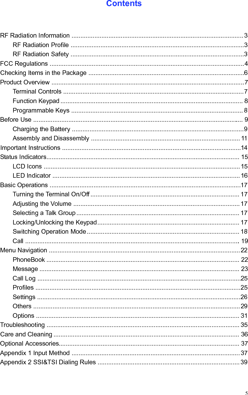
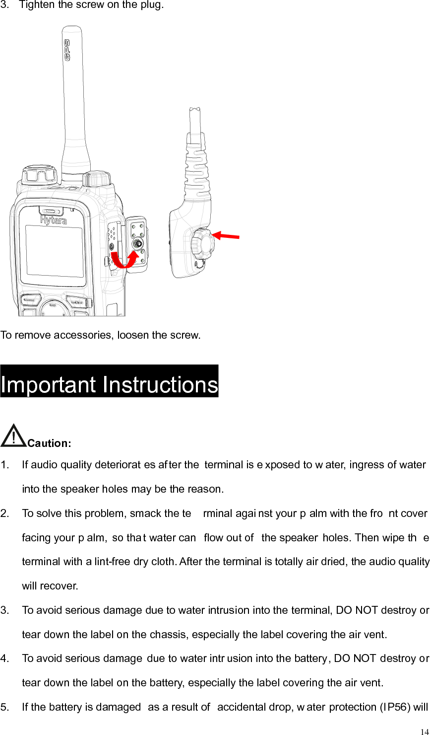
![Guide to the BABT Implementation of Annexes III and IV of the R&TTE Directive BABT 725 Annex B Issue 3 1 of 1 DECLARATION OF CONFORMITY We, Hytera Communications Co., Ltd. (manufacturer’s name ) of HYT Tower, Hi-Tech Industrial Park North, Nanshan District, Shenzhen China (address) declare under our sole responsibility that the product Product: TETRATERMINAL Model: PT580H Plus F4 Refer the declaration of TETRATERMINAL / PT580H Plus F4 (detailed description of product including name, type, model and supplementary information such as lot, batch or serial number, sources and number of items) to which this declaration relates, is in conformity with the following standards and/or other normative documents.ETSI EN 300 392-2 V3.4.1: 2010-08,ETSI EN 300 394-1 V3.2.1: 2012-10,ETSI EN 300 396-2 V1.4.1: 2011-12, ETSI EN 303 035-1 V1.2.1: 2001-12,ETSI EN 303 035-2 V1.2.2: 2003-01, ETSI EN 300 328 V1.8.1: 2012-06, ETSI EN 300 440-1 V1.6.1: 2010-08,ETSI EN 300 440-2 V1.4.1: 2010-08, ETSI EN 301 489-1 V1.9.2: 2011-09, ETSI EN 301 489-3 V1.6.1: 2013-08,ETSI EN 301 489-17 V2.2.1: 2012-09, ETSI EN 301 489-18 V1.3.1: 2002-08, EN50360:2001/A1:2012, EN50566:2013, EN62209-1:2006, EN62209-1:2006, EN62209-2:2010, EN62479:2010, EN 60950-1:2006+A11:2009+A1:2010+A12:2011 We hereby declare that [all essential radio test suites have been carried out and that] the above named product is in conformity to all the essential requirements of Directive 1999/5/EC. The conformity assessment procedure referred to in Article 10 and detailed in Annex [III ]or [IV] of Directive 1999/5/EC has been followed with the involvement of the following Notified Body(ies): TUV SUD BABT, Octagon House, Segensworth Road, Fareham, Hampshire, PO15 5RL , UK Identification mark: 0168 (Notified Body number) The technical documentation relevant to the above equipment will be held at: (name and address of EU representative) (name) Jianxiong Xie (title) Engineer 2015-11-05 (signature of authorised person) (date)](https://usermanual.wiki/Hytera-Communications/PT580HPF4/User-Guide-2860401-Page-44.png)