Hytera Communications PT580HPF4 TETRA TERMINAL with Bluetooth and GPS User Manual
Hytera Communications Corporation Ltd. TETRA TERMINAL with Bluetooth and GPS
User Manual

OWNER'S MANUAL
DIGITAL MOBILE RADIO
Preface
Thank you for purchasing Hytera PT580H Plus F4 TETRA digital terminal. The terminal
has a large translucent TFT color display, and supports both TMO and DMO modes. The
benefits that PT580H Plus F4 can deliver you will dramatically improve your working
efficiency.
To derive optimum performance from the terminal, please read the Safety Information
Booklet and Owner’s Manual carefully before use.

1
Icon Information
The following icons are available through this manual:
Caution: indicates situations that could cause damage to your terminal.
Note: indicates tips that can help you make better use of your terminal.
Term Explanation
Key Operation
Short press: to press a key and release it quickly.
Long press: to press and hold down a key for above 1.5 seconds.
Hold down: to press a key and remain holding it down.
Individual Call
Individual call is a simplex or du plex call initiated by a single user to anot her user,
involving the calling party and the called party only.
Group Call
Group call is a simplex call initiated by a single user to a group of users, involving the
calling party and all the group members.
Telephone Call
Telephone call is u sually a full duplex call initiate d between PT580H Plus F4 and a
PSTN subscriber (such as telephone user or mobile phone user).
To send or r eceive telep hone calls, the terminal must operat e in TMO mode, and
must be authorized to access public network through PSTN gateway. Telephone call
is a network service. For more details and availability of the service, please cont act
your service provider.
Emergency Call
Emergency call has the highest priority, and is very helpful for the user to request help
when emergency occurs. Generall y, it is set to group call type. Emergency call can
break off any non-emergency calls in progress.
2
DMO (Direct Mode Operation)
DMO mode allows terminals to communicate directly with each other in simplex mode,
without network restriction. But fun ctions that require n etwork access, such as
telephone call and short message, will be disallowed.
TMO (Trunked Mode Operation)
TMO mode allows terminals to communicate with each other via the TETRA network,
in half duplex or full d uplex mode. Func tions that require network access are
supported.
To operate in TMO mode, the terminal must be granted authorization by your service
provider, and must be within the network coverage.
Air Interface Encryption
An encryptio n method h elpful for pr otecting message transmitted over the air . It
encrypts dat a and signal ing transmitted betwe en the base st ation and terminal, to
protect the message from eavesdropping.
Full Duplex
Full duplex allows the ability to communicate in both directions simultaneously.
Half Duplex
Half duplex, also known as simplex, allo ws the ability to communicate in only one
direction, at a time. Two-way communication is possible, but not simultaneously.
Copyright Information
Hytera and HYT are trademarks or registered trademarks of Hytera Communications Co.,
Ltd. (“Hytera”) in PRC and/or other countries or areas. Hytera retains the ownership of its
trademarks and product names. All other trademarks and/or product names that may be
used in this manual are properties of their respective owners.
The Hytera product described in this manual may include Hytera computer programs
stored in memory or other media. Laws in PRC and/or other countries or areas protect the
exclusive rights of Hytera with respect to its computer programs. The purchase of this

3
product shall not be deemed to grant, either directly or by implication, any rights to the
purchaser regarding Hytera computer programs. Any Hytera computer programs may not
be copied, modified, distributed, decompiled, or reverse-engineered in any manner
without the prior written consent of Hytera.
Disclaimer
Hytera endeavors to achieve the accuracy and completeness of this manual, but no
warranty of accuracy or reliability is given. All the specifications and designs are subject to
change without notice due to continuous technology development. No part of this manual
may be copied, modified, translated, or distributed in any manner without the express
written permission of Hytera.
If you have any suggestions or would like to learn more details, please visit our website at:
http://www.hytera.cn.
RF Radiation Information
RF Radiation Profile
Radio Frequency (RF) is a frequency of electromagnetic radiation in the range at which
radio signals are transmitted. RF technology is widely used in communication, medicine,
food processing and other fields. It may generate radiation during use.
RF Radiation Safety
In order to ensure user health, experts from relevant industries including science,
engineering, medicine and health work with international organizations to develop
standards for safe exposure to RF radiation. These standards consist of:
¾ United States Federal Communications Commission, Code of Federal Regulations;
47CFR part 2 sub-part J;
4
¾ American National Standards Institute (ANSI)/Institute of Electrical and Electronic
Engineers (IEEE) C95. 1-1992;
¾ Institute of Electrical and Electronic Engineers (IEEE) C95. 1 – 1999;
¾ International Commission on Non-Ionizing Radiation Protection (ICNIRP) 1998;
FCC Regulations
Federal Communication Commission (FCC) requires that all radio communication
products should meet the requirements set forth in the above standards before they can
be marketed in the U.S, and the manufacturer shall post a RF label on the product to
inform users of operational instructions, so as to enhance their occupational health
against exposure to RF energy.
As a conscientious company centering on users, Hytera strictly complies with the forgoing
requirements from design, production and test.
5
Contents
RF Radiation Information .................................................................................................. 3
RF Radiation Profile ................................................................................................... 3
RF Radiation Safety ................................................................................................... 3
FCC Regulations ............................................................................................................... 4
Checking Items in the Package ......................................................................................... 6
Product Overview .............................................................................................................. 7
Terminal Controls ....................................................................................................... 7
Function Keypad ........................................................................................................ 8
Programmable Keys .................................................................................................. 8
Before Use ........................................................................................................................ 9
Charging the Battery .................................................................................................. 9
Assembly and Disassembly ..................................................................................... 11
Important Instructions ...................................................................................................... 14
Status Indicators.............................................................................................................. 15
LCD Icons ................................................................................................................ 15
LED Indicator ........................................................................................................... 16
Basic Operations ............................................................................................................. 17
Turning the Terminal On/Off ..................................................................................... 17
Adjusting the Volume ............................................................................................... 17
Selecting a Talk Group ............................................................................................. 17
Locking/Unlocking the Keypad ................................................................................. 17
Switching Operation Mode ....................................................................................... 18
Call ........................................................................................................................... 19
Menu Navigation ............................................................................................................. 22
PhoneBook .............................................................................................................. 22
Message .................................................................................................................. 23
Call Log .................................................................................................................... 25
Profiles ..................................................................................................................... 25
Settings .................................................................................................................... 26
Others ...................................................................................................................... 29
Options .................................................................................................................... 31
Troubleshooting .............................................................................................................. 35
Care and Cleaning .......................................................................................................... 36
Optional Accessories ....................................................................................................... 37
Appendix 1 Input Method ................................................................................................ 37
Appendix 2 SSI&TSI Dialing Rules ................................................................................. 39

6
Checking Items in the Package
Please unpack carefully and check that all items listed below ar e received. If any item is
missing or damaged, please contact your dealer.
Battery Charg er Power Adapter
Antenna Belt Clip S trap
Owner’s Manual Safety Information Booklet Quick Reference Guide
Portable Terminal
7
Note: Frequency band is marked on the label of antenna; if not, please refer to the
label on the terminal for frequency band information.
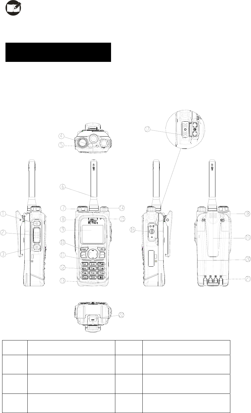
Product Overview
Terminal Controls
No. Part Name No. Part Name
○
1 SK1 (programmable) ○
2 PTT Key
○
3 SK2 (programmable) ○
4 Emergency Key
○
5 LED Indicator ○
6 Antenna
8
○
7 Encoder/channel selector
knob
○
8 Receiver
○
9 Translucent TFT C olor
Display
○
10 Function Keypad
○
11 Speaker ○
12 Numeric Keypad
○
13 Duplex Microphone ○
14 Volume Control knob
○
15 Simplex Microphone ○
16 Accessory Jack Cover
○
17 Accessory Jack ○
18 Strap Hole
○
19 Belt Clip ○
20 Battery
○
21 Battery Charging pole ○
22 Battery latch
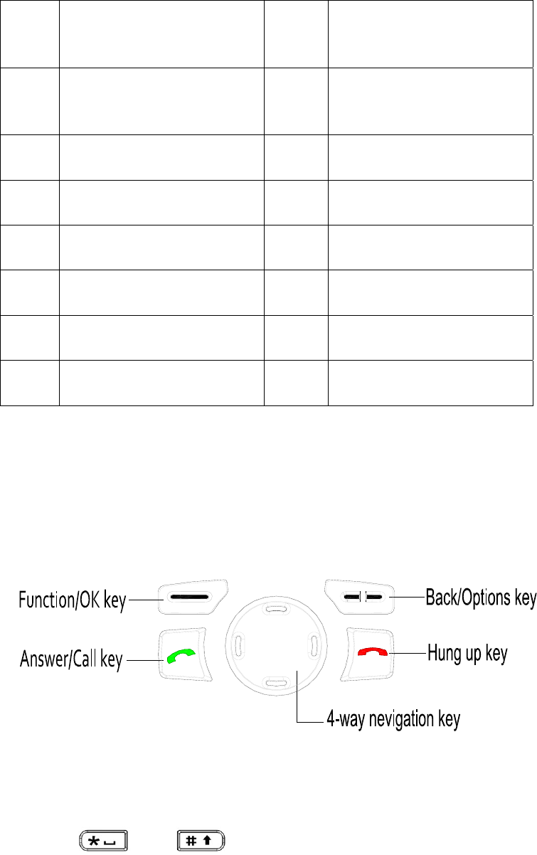
Function Keypad
Programmable Keys
Most of the terminal’s keys including SK1, SK2, four Navigation Keys, Call Key, numeric
keys 1-9, and , can be set as shortcuts to terminal functions or menus.
Then you may quickly access menus or features through press of a key.
Available options are:
z PhoneBook
z Create Message

9
z Inbox
z Outbox
z D rafts
z Dialed Calls
z Received Calls
z Missed Calls
z Profiles
z Date&T ime
z Keyp ad Lock
z Dis play Saver
z PIN Code
z Change PIN Code
z My Info
z Calen dar
z Select Mode
Note: Long and short press of SK1 or SK2 can be assigned with different functions.
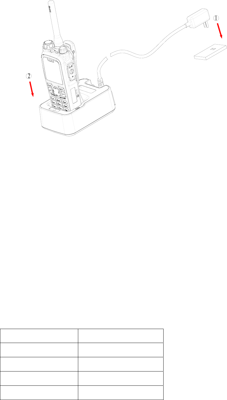
Before Use
Charging the Battery
Only use the charger and battery specified by Hyt era. The charge LED will indicate the
charging progress.
10
Procedures
1. Connect the power adapter to an AC source socket. See arrows .①
2. Place the terminal with the batter y at tached into the charg er. See arr ow ②. Make
sure the battery’s charging pieces are in good contact with the charger’s terminals.
3. The charging process begins when the charger LED solidly glows red.
4. When char ging is complete, green LED glows. Then remo ve the batter y or the
terminal from the charger.
The standard 1800mAh Li-Ion battery may take 3 hours for an ordinary charge. But before
initial use, please charge it for 5 hours to achieve optimal battery performance.
LED Indications and Charging Progress
LED Indicator Status
LED flashes red slowly. Standby (no load)
LED solidly glows red. Charging
LED solidly glows orange. Charging (above 85%)
LED solidly glows green. Fully charged
11
LED flashes red rapidly. Failure
Note: Be sure to read the Safety Info rmation Booklet, to get necessa ry safety
information.
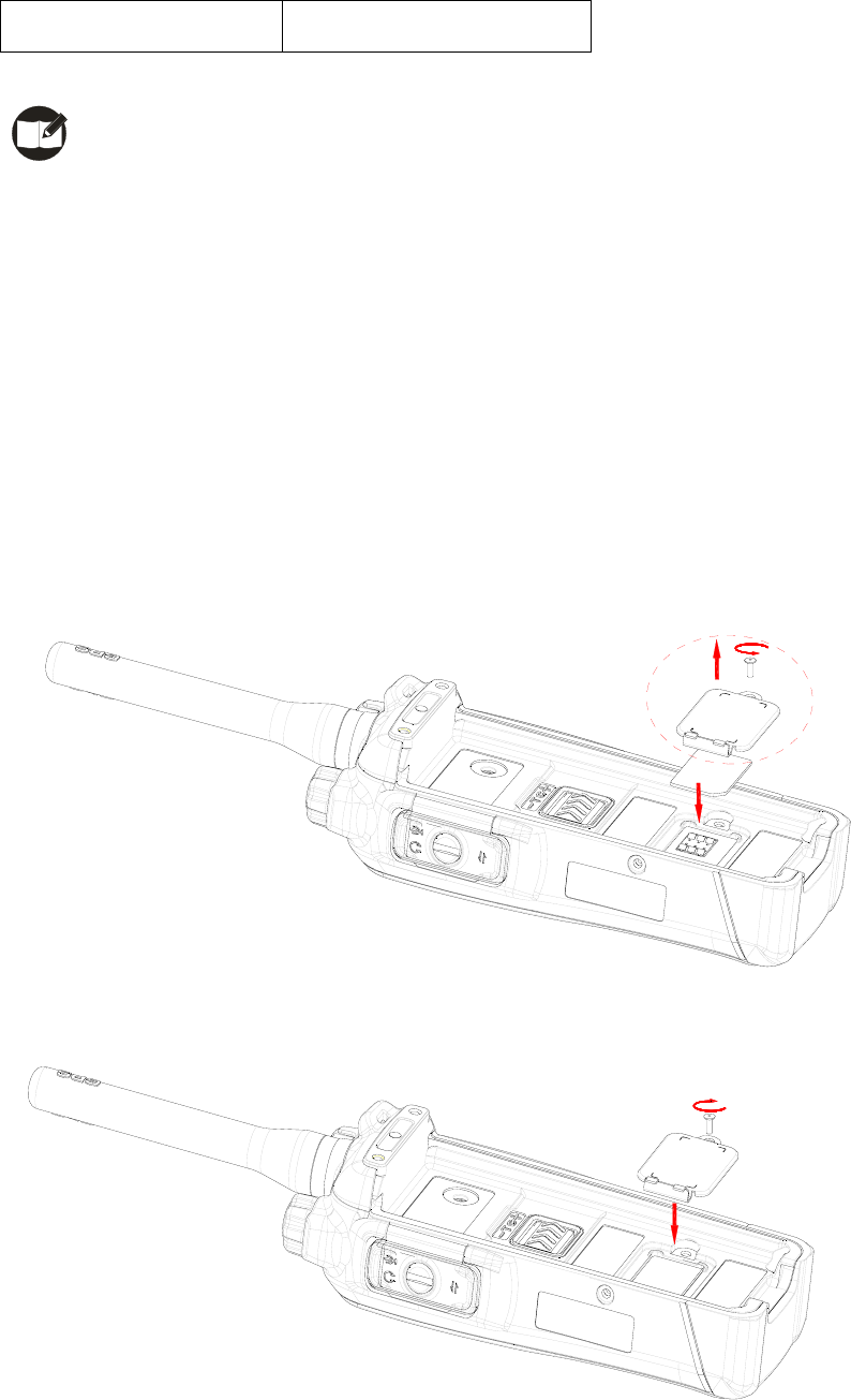
Assembly and Disassembly
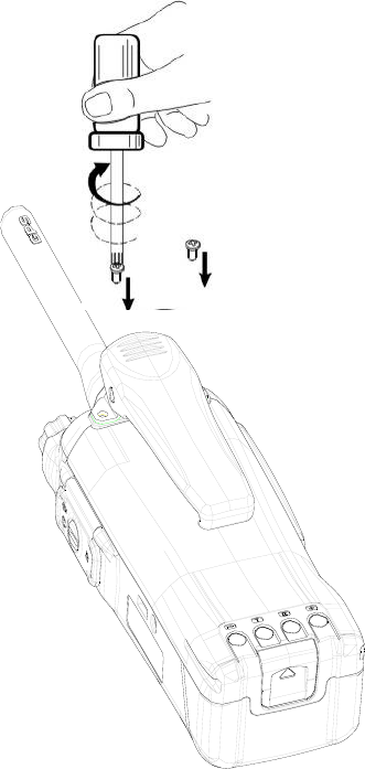
Attaching the SIM Card
1. Open the SIM card cover by loosenin g screw, and insert the SIM card prop erly into
the holder.
2. Close the SIM card cover ,and fasten the screw tightly .
Apply step 1 when you need to take out the SIM card.
12
Note: SIM card related services are not supported by the te rminal currently, and
require future software upgrade.
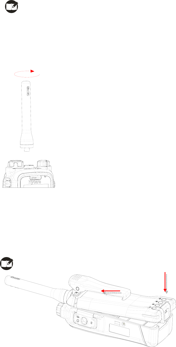
Attaching the Antenna
Turn the antenna clockwise to fasten it.
To remove the antenna, rotate it counter-clockwise.
Attaching the Battery
1. Fit the extensions at the top of the battery into the slot at the top of the terminal’s body.
2. Slightly press the bottom of the battery until a click is heard,
Note: If the battery is loose or unsecured, please remove and attach it again.
13
To remove the battery , turn of f the terminal first. Then slide the battery la tch upwards to
unlock the battery.
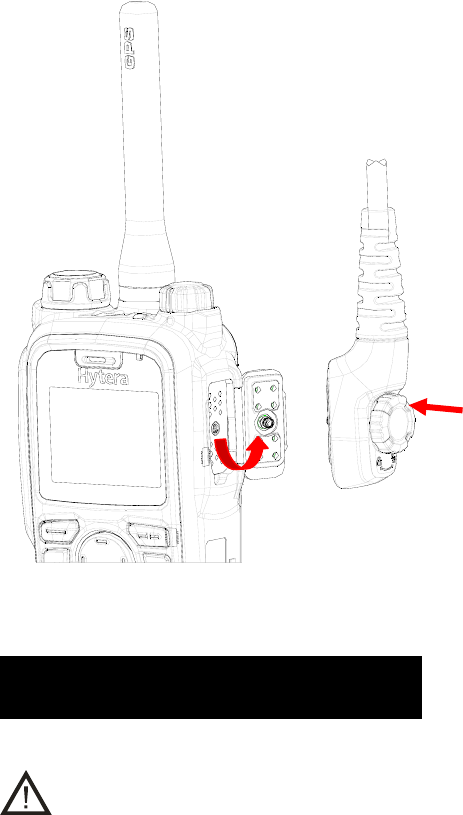
Attaching the Belt Clip
1. Remove the screws in the main radio.
2. Align the screw holes on the belt clip with those on the terminal’s body, and the n
tighten the screws.
To remove the belt clip, loosen the screws.
Attaching Accessories
1. Open the accessory jack cover as the arrow shown.
2. Align the plug with the accessory jack.
14
3. Tighten the screw on the plug.
To remove accessories, loosen the screw.
Important Instructions
Caution:
1. If audio quality deteriorat es after the terminal is e xposed to w ater, ingress of water
into the speaker holes may be the reason.
2. To solve this problem, smack the te rminal agai nst your p alm with the fro nt cover
facing your p alm, so tha t water can flow out of the speaker holes. Then wipe th e
terminal with a lint-free dry cloth. After the terminal is totally air dried, the audio quality
will recover.
3. To avoid serious damage due to water intrusion into the terminal, DO NOT destroy or
tear down the label on the chassis, especially the label covering the air vent.
4. To avoid serious damage due to water intr usion into the battery, DO NOT destroy or
tear down the label on the battery, especially the label covering the air vent.
5. If the battery is damaged as a result of accidental drop, w ater protection (IP56) will
15
not be guaranteed unless you replace it with a new and approved one.
Below texts should be deleted
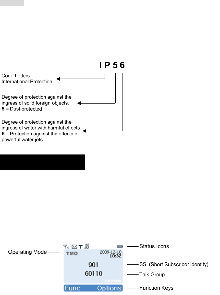
IP Code --
The IP Code is a designation that indicates the level of protection against ingress of solid
foreign objects and water. It consists of the letters IP (International Protection) followed by
two numerals. Take IP56 for example:
Status Indicators
LCD Icons
The LCD of your terminal displays the termi nal status, text entries, and men u items. The
following are the icons that appear on the terminal’s display.
S tandby Interface
16
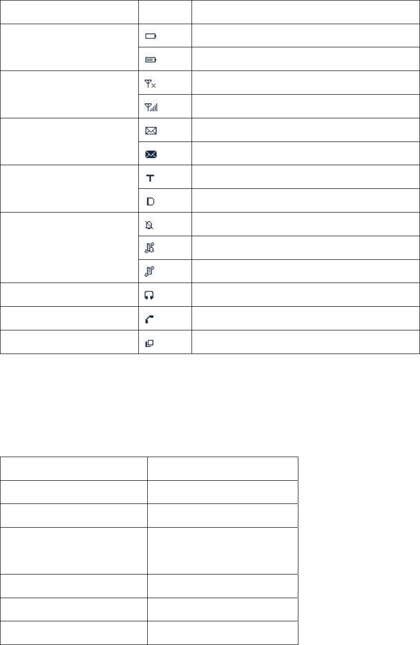
Status Icons (TMO and DMO)
Icon Name Icon Terminal Status
Battery Strength Icons Low battery
More bars indicate more battery power
RSSI No signal
More bars indicate better signal strength
Message Icons Unread message
Inbox is full and all are unread messages
Operation Mode Icons The terminal currently operates in TMO mode
The terminal currently operates in DMO mode
Profiles Icons
Silent
Normal (ring and vibration)
Vibration only
Accessory Icon An audio accessory is connected
Call Icon A call is in progress
Talkgroup Selection Icon Selecting a talk group
LED Indicator
The top LED indicator will help you easily identify current terminal status.
Terminal Status LED Indicator
Transmitting a call LED solidly glows red.
Receiving a call LED solidly glows green.
Telephone Call
LED solidly glows red on both
parties.
Low battery LED flashes red slowly.
DMO mode channel free LED flashes green slowly.
DMO mode channel busy LED solidly glows orange.

17
Basic Operations
Turning the Terminal On/Off
To turn the terminal on, hold d own t he Power On/Off key un til the terminal shows the
power-up screen.
To turn the terminal off, long press the Power On/Off key.
Adjusting the Volume
You may adjust call volume through the knob. Rotate the knob clo ckwise to increase the
volume, or counter-clockwise to decrease the volume. Then press OK to save the volume.
To adjust alert tone volume, go to “Profiles->Normal->Settings->AlertVolume”.
Selecting a Talk Group
1. In the home screen, press the knob to sw itch it to t alk group selection mode (th e
terminal displays the icon ).
2. Then rotate the knob to select your desired talk group.
3. Name of the current talk group will appear on the home screen.
You may also set a talk group as the default group. Go to “Options->Talk Group->Selected
List”. See Selected List for more details.
Note: Pressing PTT in the home screen will transmit a group call to the current talk
group.
Locking/Unlocking the Keypad
To lock or unlock the keypad, press OK and then .
When the keyp ad is locked, you ca n also ans wer and reply to calls. Af ter a call is

18
completed, the keypad will return to be locked.
Switching Operation Mode
You may switch the terminal betw een TM O a nd DMO thr ough any of the followin g
methods:
1. Menu selection
Press the Options key to access the menu, and then select TMO or DMO.
Talk Group
[Options]
DMO Options
TMO
Language
Talk Group
TMO Options
DMO
Language
GPS
GPS
2. Function key press
In the home screen, press the Select Mode key to switch between TMO and DMO.

19
Call
Individual Call
¾ Transmitting an Individual Call
DMO Mode
1. Input the number you w ant to call through the keyp ad, or go to the menu
PhoneBook or Call Log to select the contact you want to call.
2. Then hold down the PTT and speak into the microph one, to transmit a simplex
call.
TMO Mode
Transmitting a call through menu
1. Go to the menu PhoneBook or Call Log to select the contact you want to call.
2. Hold down the PTT to transmit a simplex call, or press to transmit a duplex
call.
Transmitting a call through Manual Dial
1. Input the number you want to call through the keypad.
2. Press Ctype to select Private No (it will appear on the screen).
3. Hold down the PTT to transmit a simplex call, or press to transmit a duplex
call.
Note: Entry of private number must comply with the SSI&TSI dialing rules. See
Appendix 2 SSI&TSI Dialing Rules for more details.
¾ Receiving and Responding to an Individual Call
DMO Mode
When the PTT is in released state, the terminal is always ready to receive calls.
When the other party stops talking, you can hold down the PTT to call back.
TMO Mode
Simplex Call
When a simplex call is received, you can receive without an y operation, unless the

20
LCD prompts you to p ress the PTT to answer a call. When the other p arty stop s
talking, you can hold down the PTT and speak into the microphone to call back.
Duple x Call
When a dupl ex call is received, you can press to receive. And both parties can
speak simultaneously without any operation.
Group Call
Available talk group s are preset by your de aler. DMO mode support s up to 1024 t alk
groups, and TMO mode supports up to 2048 t alk groups. Both DMO and TMO suppor t
group call, and operations are the same in both modes.
¾ Transmitting a Group Call
1. In the home screen, press the knob to swit ch it to talk group selection mode (the
terminal displays the icon ).
2. Rotate the knob to select a talk group you want to call.
3. Press the knob again or press OK to confirm.
4. Hold down the PTT to transmit a group call.
Note:
In TMO mode, you can tr ansmit a gro up call to a talk group on ly after it is attached
successfully. If you failed to att ach a talk group, the reason m ay be that the group
does not exist in the network, or you are out of the network coverage.
¾ Receiving and Responding to a Group Call
When a group call is received, you need no t make any operation. When the calling
party stops talking, you can hold down the PTT and speak into the microphone to call
back.

21
Telephone Call
¾ Transmitting a Telephone Call
1. Input the number you want to call through the keypad.
2. Press Ctype to select PABX or PSTN (it will appear on the screen).
3. Press to transmit a telephone call.
¾ Answering a Telephone Call
When a tele phone call is received, yo u can press to answer the call. And bot h
parties can speak simultaneously without any operation.
To reject or to hang up a telephone call, press .
Note: The te rminal must be set with a ppropriate Gateway No. Please cont act your
network operator for more details.
Emergency Call
Both DMO and TMO support emergency call, and operations are the same in both modes.
Long press the top Emergency key to transmit a n emergency call. To terminate the call,
press .
In DMO mo de, emergen cy calls are transmitt ed to the default t alk group. And in TMO
mode, the target receiver is programmable through the programming software.
Note: Please speak into the dupl ex microphone when sending a duplex call, or the
simplex microphone when sending a simplex call.
22
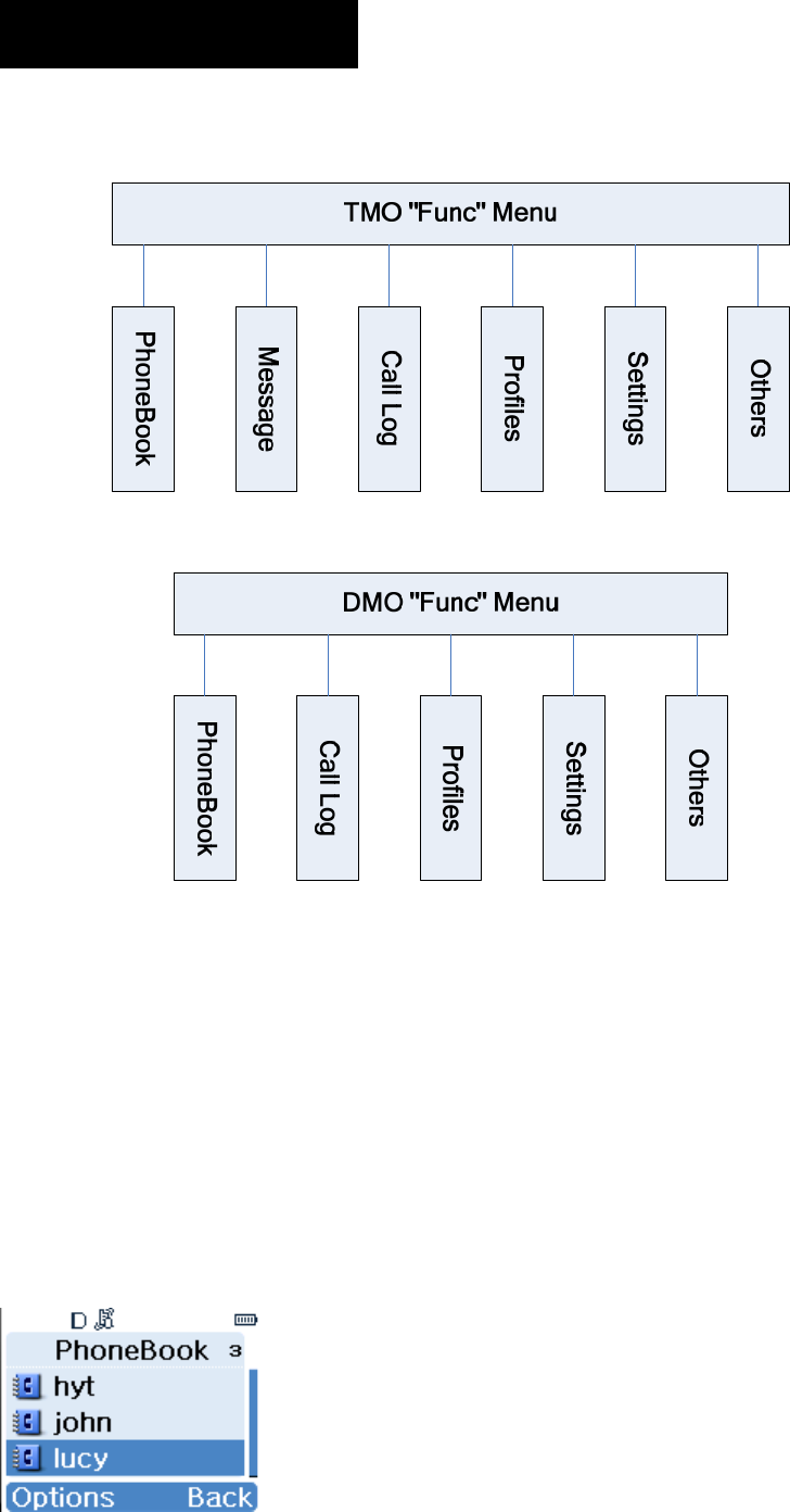
Menu Navigation
Press the Function key to access the menu list. T he operations in TMO mode are the
same as that in DMO mode. Here we are going to introduce all menu items based on TMO
mode.
PhoneBook

23
This menu is used to store your contact information. It can contain up to 512 entries. Each
entry consists of contact name and contact number. To access this menu, press “Func ->
PhoneBook” in idle mode, and then you can perform these operations:
■Create new contact
■View a contact
■Modify a contact
■Delete a contact
■Delete all contacts
■View phonebook memory
■Search a contact (by name)
■Call a contact
With this me nu, you can make a duplex (for TMO only) or simplex call to a contact. The
method is as follows:
1. Select a contact from the menu;
2. Press and hold down PTT key to make a simplex call, or p ress to ma ke a
duplex call.
Alternatively, you can make a duplex call by selecting “Options -> Call”.
Message
■Create Message
(1) Status Message
Status Message is predefined by your dealer. You can choose to read and send them, but
no editing is available.
(2) User Message

24
This option allows you to create a new text message with 140 bytes at most. The receiving
party can either be an individual or a group.
■Inbox
All received messages a re saved he re. It can co ntain up to 50 entries. When a ne w
message arrives, the ico n will appear in the st atus bar. Press View to read the new
message rig ht away or press Back to view it later . Whe n th e inbo x is overflow ed wi th
unread messages, the icon will appear in the status bar. Please sort your inbox in
time to receive more messages. For any message, you can perform these operations:
Reply: to reply to the message sender;
Delete: to delete the current message;
Delete All: to delete all received messages;
Individual: to forward the message to an individual user;
Group: to forward the message to a group;
Edit: to edit the content of the message;
Extract No.: to extract the number;
Call: to call the message sender.
■Outbox
The outbox can save up to 20 sent messages. The operations available for any message
in outbox are: Delete, Delete All, Individual, Group, Edit (available to User Message only)
Extract No., and Call.
■Drafts
You can save up to 10 drafted messages her e. For any me ssage, you can choose t o
delete, edit or send it.
25
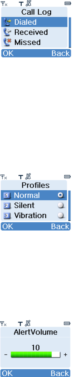
Call Log
This terminal can save up to 20 entries in the option Dialed C alls, Received Calls and
Missed Calls respectively . W hen there is a misse d call, appr opriate indicat ions will be
given on the display.
After selecting an entry, these options are available: Call, View, Save, Delete, Delete All.
Profiles
■Normal
In this mode, the terminal will alert yo u to an incoming call or a new message by givin g
ring or vibr ation indication. T o match your actual needs and prefere nces, you ca n
customize the following parameters:
¾ Alert Volume
You can decrease or increase the volume level using Left or Right navigation key.
¾ Alert Type
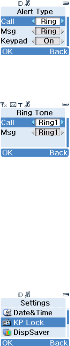
26
You can use Left or Right key to select your desired alert type for an incoming call, a new
message or keypad press. For an incoming call or a new message, the avai lable options
include: Off, Ring, Vibra and Rg&Vb; for keyp ad press, the available optio ns include On
and Off.
¾ Ring Tone
You can use Left or Right key to select your desired alert ton e for an inco ming call or a
new message.
■Silent
In this mode, no ring or vibration indication will be given when a new call or new message
arrives.
■Vibration
In this mode, only vibration indication will be given when a new call or new message
arrives.
Settings
27
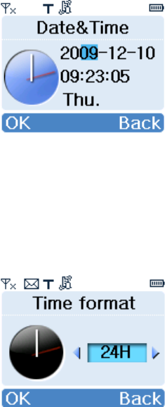
■Date&Time
This option allows you to set the current dat e, time and time format. The method is as
follows:
¾ To set date and time
Press Left or Right key to select the item to be set, and then input the right value through
keypad. When the curre nt time is displaye d in 12 Hour format, press Up or Down key to
toggle it between AM and PM.
¾ To set time format
You can toggle the time form at between 24H and 12H using Left or Right key. When al l
settings are done, press OK to make them take effect.
■KP Lock
This option allows you to enable o r disable the Auto Keypad Lock feature. If it is enabled,
the keypad will be locked automatically after the programmed time (10 seconds by default)
elapses.
■DispSaver
This option allows you to enable or disable the screensaver. If enabled, it will be activated
automatically after the programmed time (15 seconds by default) elapses.
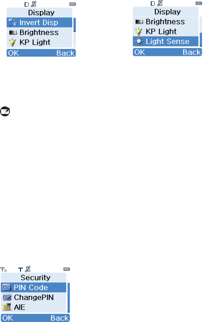
■Display
28
¾ Inv ert Disp
This option allows you to invert the displayed information by 180° so that you can access it
easily.
Note: when the display is inverted, the function of OK key and Back key exchanges.
¾ Brightness
You can use Left or Right key to adjust the brightness level.
¾ KP Light
This option allows yo u to enabl e or dis able k eypad lig ht. The lightin g dur ation i s
programmable with the programming software.
¾ Light Sense
When this feature is enabled, the terminal will sense t he ambient lighting conditions
automatically to determine the brightness of backlight.
■Security
¾ PIN Code
To set PIN code On or Off, you will be required to input the PIN code. The terminal will be
locked when wrong PIN code is entered up to the predefined times. To unlock it, you need
to enter the right PUK code. Then the terminal will bring you to an interface, where you
can reset your PIN code or press Back key to restore it to default value. Ho wever, when
wrong PUK code is ente red up to th e predefin ed time s, the terminal will be disabled

29
temporarily and shows “Radio Disabled”.
Note: the number of time s that you are a llowed to input wrong PIN or PUK code is
programmable through the programming software. When the terminal is disabled, contact
your de aler to activate it. The default PIN code is 1234, and t he default PUK code is
12345678.
¾ Change PIN code
This option allows you to change the PIN code. Before c hanging it, you need to enter the
old PIN code correctly. Then you will be asked to input your new PIN code twice. Please
make sure the codes you entered are identical; otherwise, you have to reset it again.
■Man Down
When this feature is enabled, the terminal will se nd an emer gency call to the predefined
ID automatically once it falls over or t ilts by 45°. At the same time, it would sound sharp
alarm tone. With this feature, you can enjoy enhanced personal protection.
■Reset All
This option allows you to restore all settings to default value. To perform this operation,
you need to input the right PIN code.
Others
30
■My Info
Under this option you can view some basic information about the terminal, including MCC,
MNC and ISSI.
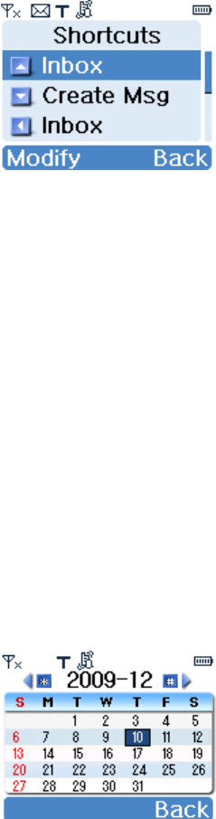
■Shortcuts
To enhance operation convenience, you can assign your desired function to a specific key
as shortcut. Then you can press the key to access a function easily.
¾ To create a shortcut
1. Select Shortcuts to access the list of shortcut keys;
2. Select your desired key, and press Modify to access the list of assignable functions;
3. Select your desired function, and press OK to confirm.
¾ To cancel a shortcut
1. Select Shortcuts to access the list of shortcut keys;
2. Select the shortcut ke y to be cance lled, and press Modify to ac cess th e lis t o f
assignable functions;
3. Select Empty, and press OK to confirm.
■Calendar
This option allows you to view calendar information.
31
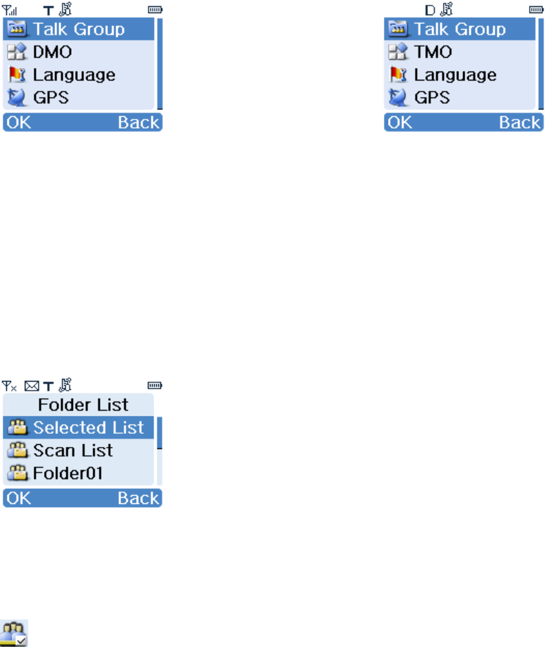
Options
【Options】Menu for TMO 【Options】Menu for DMO
In the home screen, press Options to access this menu. Here we are going to introduce
all menu items based on TMO mode.
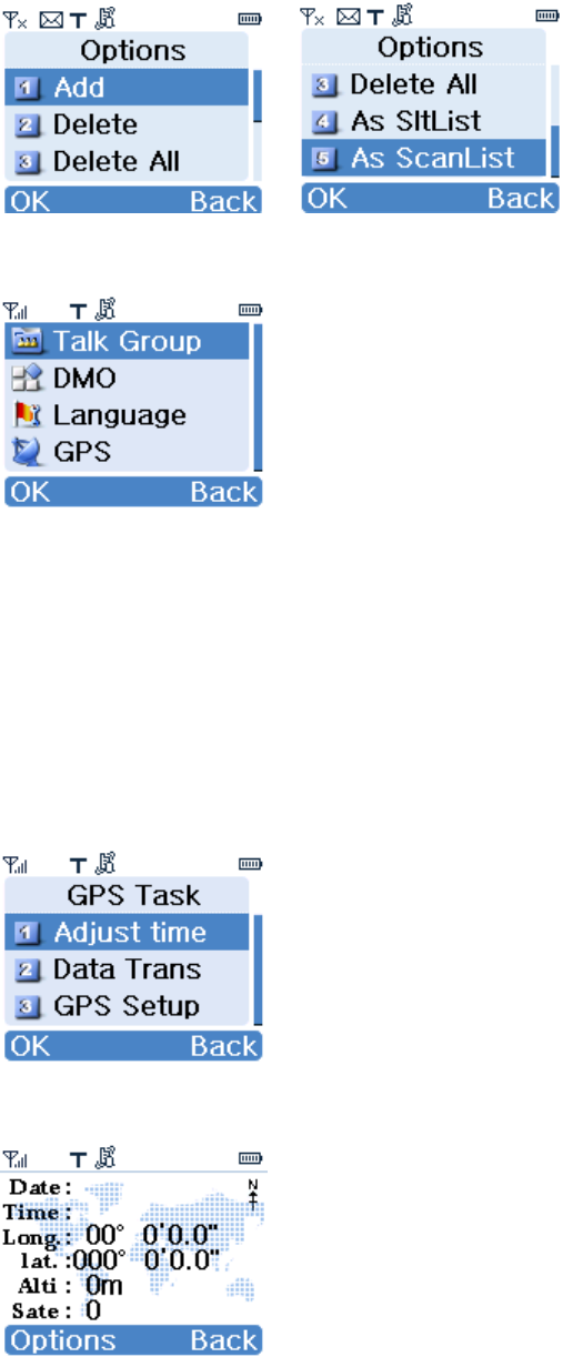
Talk Group
Under this option, you wi ll see Selected Lis t, Scan List, and one or mor e static folders
created through programming software, as shown in following picture:
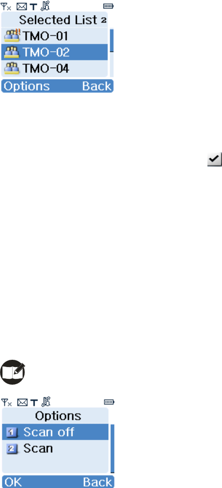
¾ Selected List
Under this option, you can set a talk group as the default group. Alternatively, you can do
so by rot ating the knob in the home screen. The default grou p is indicate d by the icon
, as shown in following picture.
In the home screen, you can make a group call to the default group by pressing PTT key
directly.
To add gr oups to the Selected List, enter a st atic folder, and select “As SltList” from
Options.
32
¾ Scan List
You can receive calls only from grou ps that are included in th e scan list a nd have bee n
attached successfully (indicated by the icon ). But you can always receive from the
default group and the emergency group, regardless of the foregoing condition.
After entering the scan list, you can perform the following operations:
Scan On: to enable Scan feature and to attach all talk groups in the scan list;
Scan Off: to disable Scan feature and to detach all talk groups except background group,
default group and emergency group.
Scan: to attach all talk groups in the scan list.
To add gro ups to the Scan List, enter a stat ic folder, and select “As ScanList” from
Options.
Note: Scan List is available for TMO mode only.
¾ Static Folder
After accessing any of the folders, you can perform the following operations:
Add: to include a talk group into the current folder;
Delete: to remove a talk group from the current folder;
Delete All: to remove all talk groups from the current folder.
As SltList: to add all talk groups in the current folder to Selected List;
As Scan List: to add all talk groups in the current folder to Scan List.
33
DMO
You can use this option to make your termi nal work in DMO mode. In DMO mode, this
option shall be TMO. Likewise, you can use it to make your terminal work in TMO mode.
Language
This option allows you to select your favo rable langu age. C urrently, this terminal only
supports English and Simplified Chinese.
GPS
¾ Display of GPS Data
GPS data includes date, time, longitude, latitude, altitude, and number of satellites. Date
and time are correlative to the selected time zone.
¾ Adjust Time

34
This option allows you to calibrate the time currently displayed on your terminal with GPS
time, and is correlative to the Time Zone option.
¾ Data Transmit
You may choose to transmit GPS dat a to an in dividual user , a group of users, or th e
control center. This option is correlative to the Send Mode option.
Operations to send GPS dat a are similar to that of short message. Received GPS dat a
are saved in “Message->Inbox”.
Individual
To transmit GPS data to an individual user.
Group
To transmit GPS data to all users included in a certain group.
Note: To implement the Data Transmit function, the terminal must operate in TMO
mode. And GPS data is deemed valid only when the GPS receiver has received data from
at least 3 satellites.
Otherwise, “GPS dat a invalid” will appear on the screen when you attempt to transmit
GPS data.
¾ GPS Setup
You may set the time zone and select a method to transmit GPS data.
Time Zone
You may select a time zone according to term inal location or yo ur preference. There ar e
25 available time zones, used for time calibration.
Send Mode
You may choose wheth er to send GPS dat a to a specified t arget per iodically. The
transmission interval is programmable by your dealer. There are two transmission modes
available:
z Manual Send
To manually transmit GPS data to other terminals.
z Auto Send
To periodically transmit GPS data to other terminals.

35
Troubleshooting
Symptom Solution
The termin al can no t be
powered on.
Please check whether battery power is too low or whether
the battery fails to function.
Network re gistration fails or
network can not be found.
1. Please check the signal strength and see whether
your terminal is within the network coverage.
2. Contact the network administrator, and confirm
whether the terminal has acquired app ropriate
authorization.
3. Check whether your terminal is in TMO mode.
Unable to make a call
1. Please check the signal strength and see whether
your terminal is within the network coverage.
2. Check whether the called p arty is within the netw ork
coverage.
Unable to call or receive f rom a
specific group.
1. Check whet her your ter minal is a member of the
target group.
2. Check whether your terminal is authorized to access
the target group.
Unable to make a call in DMO
mode
1. The called party is out of coverage.
2. The called party is not in DMO mode.
Half duple x transmission is
terminated.
Overlong time of transmission makes the timer expire.
Normal call is interrupted.
Check whether a terminal is making a pre-emptive priority
call or emergency call.
For the same st atus me ssage,
the content displayed at the
sending p arty and at the
Please check whether both p arties have assign ed the
same content for this status message ID.

36
receiving party varies.
Abnormal disconnection during
a call
1. Check the signal strength in TMO mode.
2. Check whether you are in a place where the sign als
can be shielded (such as basement and tunnel) and
whether the other party is out of coverage.
3. Check the battery strength.
Note: If the above solutions can not fix your problems, or you may have some other
queries, please contact us or your local dealer for more technical support.
Care and Cleaning
To guarantee optimal pe rformance as well as a long service l ife of your te rminal, please
follow the tips below.
Terminal Care
Keep the terminal far away from substances that can corrode the electronic circuit;
Do not hold the terminal by its antenna or earpiece cable directly;
Attach the accessory jack cover when accessory is not connected.
Terminal Cleaning
Clean up the dust and fine particles on the terminal parts with a clean and dry lint-free
cloth or a brush regularly.
Use a non-w oven cloth with neutral cleanser to clean the keys, control knobs, LCD
and jacks af ter long-time use. Do not use chemical prep arations such as st ain
removers, alcohol, sprays or oil prep arations. Ma ke sure the terminal is completely
dry before use.
Caution: Power off the terminal and remove the battery before cleaning.
37
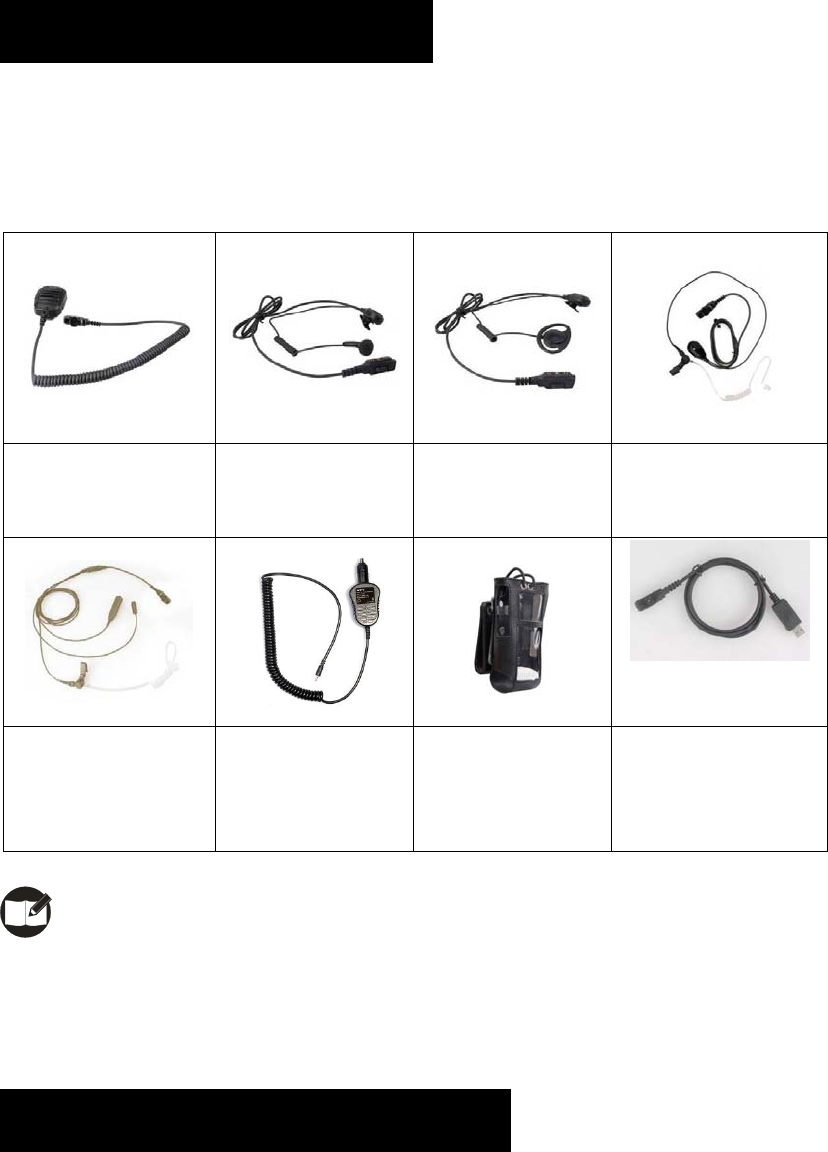
Optional Accessories
The following items are the main optional accessories for the terminal, and please consult
your local dealer for more other accessories.
Remote Speake r
Microphone (IP57)
SM18N1
Earbud w ith on-MIC
PTT ESN10
D-earset with in-line
Microphone EHN12
Earpiece w ith on-MIC
PTT & Transparent
Acoustic Tube EAN16
3-Wire Sur veillance
Earpiece w ith
Transparent Acoustic
Tube (beige) EAN17
Vehicle Adapter
CHV09
Leather Carr ying
Case ( swivel)
LCY002
Programming Cabl e
(USB to serial port)
PC36
Note: Use the accessories specified by Hyte ra only. If not, Hytera shall not be liabl e
for any losses or damages arising out of use of unauthorized accessories.
Appendix 1 Input Method
You can enter aliases, numbers or messages using the keyp ad. This ter minal suppor ts
these input methods: Simp lified Chinese Pinyin ( 拼), English ( ABC/abc) and Number
38
(123).
Switch of Input Method
In input mode, press to switch to your desired input method. The appropriate
symbol will appear on top right corner of the screen;
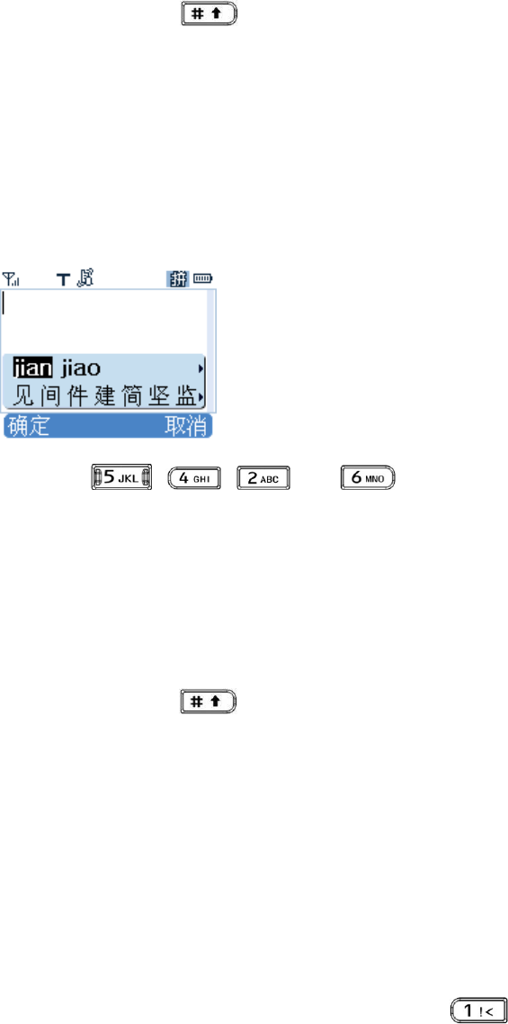
Simplified Chinese Pinyin
Enter the pinyin through alphanumeric keys; then a list of possible combinations and
corresponding characters will appear; For exam ple, to input the Chinese character
“间”:
1. Press , , and in order;
2. Press OK to move the cursor from Pinyin area to Chinese character area;
3. Use the navigation keys to scroll to the target character “间”;
4. Press the OK key to enter the selected character.
Switch between Uppercase and Lowercase
In input mode, press to switch to your desired input method. All English
letters are distributed among 8 alphanumeric keys. Press appropriate key repeatedly
to get and enter your desired letter
Number
When the input method is switched to Number , press appropriate key to enter your
desired number.
Punctuation
In Simplified Chinese Pi nyin/English mode, press to enter your desired
punctuations; while in Number mode, it is not allowed to enter any punctuation.
Space

39
In English/Number mode, long press to enter a space, and short press it to
enter “*”;
To enter a s pace in Simplified Chine se Pinyin mode, pr ess and then select
the space (the first one).
Note: short press Back key to delet e the enter ed c haracter one b y on e, or long
press it to delete all entered characters at a time.
Appendix 2 SSI&TSI Dialing Rules
This terminal support s these dialing methods: SSI&TSI, PABX and PSTN. Each metho d
shall follow a specific dialing rule. C urrently, this terminal is only cap able of checkin g
SSI&TSI dialing rules. When y ou want to call a PABX or PSTN subscriber , please input
the target number directly through the keypad. SSI&TSI dialing rules are as follows:
z For target number less than 8 digits, input it directly;
For example, when MCC = default va lue, MNC = default value and ISSI = 504, you
just need to input 504 or 00000504 to make the call;
z For target number with 9-13 digits, input MNC+ISSI;
In this case, ISSI must be 8 digits long, and add 0 before the first digit to supplement
the balance when it is less than the said length. For MNC, input it as it is.
For example, when MCC=default valu e, MNC=20 and ISSI=504, you need to input
2000000504 or 0002000000504 to make the call;
z For target number over 13 digits, input MCC+MNC+ISSI;
In this case, ISSI mu st be 8 digit s lo ng, MNC must be 4 or 5 digits long and MCC
must be 3 digits long. Add 0 before the first digit to supplement the balance when any
of them is less than the said length;
For example , when MCC = 460, MNC = 20 and ISSI = 504, you need to input
4600002000000504 or 460002000000504 to make the call.

40
Note: MCC stands for Mobile Country Code, MNC stands for Mobile Netw ork Code
and ISSI stands for Individual Short Subscriber Identity.

Disposal and recycling information
This symbol (with or without a solid bar) on the device, batteries (if included), and/or the
packaging, indicates that the device and its electrical accessories (for example, a
headset, adapter, or cable) and batteries should not be disposed of as household
garbage. These items should not be disposed of as unsorted municipal waste and
should be taken to a certified collection point for recycling or proper disposal.
For more detailed information about device or battery recycling, contact your local
city office, household waste disposal service, or retail store.
Disposal of the device and batteries (if included) is subject to WEEE Directive
Recast (Directive 2012/19/EU) and Battery Directive (Directive 2006/66/EC). The
purpose of separating WEEE and batteries from other waste is to minimize the
potential environmental impacts and human health risk of any hazardous
substances that may be present.
Battery replacement warning
Risk of explosion if the battery is replaced by an incorrect type.
This product contain build in battery that need to be removed by a specialist
before the product disposal mandatory
Keep the battery away from excessive heat and direct sunlight . Do not place it
on heating device such as microwave Owen stoves or radiators Battery may
explode if overheated. Recommended if possible
1)Risk of explosion if battery is replaced by an incorrect type.
2)Dispose of used batteries according to the instructions.
Maximum SAR values: 0.553W/Kg (10g) for Body,0.266W/Kg (10g) for Face.
This equipment operating voltage is DC 6.29V~8.51V.
This equipment operating temperature is -20 °C~55°C.
This equipment may be operated in GB, France, Germany, Britain, Italy, Spain,
Portugal, Greece.

Guide to the BABT Implementation of Annexes III and IV of the R&TTE Directive
BABT 725 Annex B Issue 3
1 of 1
DECLARATION OF CONFORMITY
We, Hytera Communications Co., Ltd.
(manufacturer’s name )
of
HYT Tower, Hi-Tech Industrial Park North, Nanshan District, Shenzhen China
(address)
declare under our sole responsibility that the product
Product: TETRATERMINAL
Model: PT580H Plus F4
Refer the declaration of TETRATERMINAL / PT580H Plus F4
(detailed description of product including name, type, model and supplementary information such as lot, batch or
serial number, sources and number of items)
to which this declaration relates, is in conformity with the following standards and/or other normative documents.
ETSI EN 300 392-2 V3.4.1: 2010-08,ETSI EN 300 394-1 V3.2.1: 2012-10,ETSI EN 300 396-2 V1.4.1: 2011-12,
ETSI EN 303 035-1 V1.2.1: 2001-12,ETSI EN 303 035-2 V1.2.2: 2003-01, ETSI EN 300 328 V1.8.1: 2012-06,
ETSI EN 300 440-1 V1.6.1: 2010-08,ETSI EN 300 440-2 V1.4.1: 2010-08, ETSI EN 301 489-1 V1.9.2: 2011-09,
ETSI EN 301 489-3 V1.6.1: 2013-08,ETSI EN 301 489-17 V2.2.1: 2012-09,
ETSI EN 301 489-18 V1.3.1: 2002-08, EN50360:2001/A1:2012, EN50566:2013, EN62209-1:2006,
EN62209-1:2006, EN62209-2:2010, EN62479:2010, EN 60950-1:2006+A11:2009+A1:2010+A12:2011
We hereby declare that [all essential radio test suites have been carried out and that] the above named product
is in conformity to all the essential requirements of Directive 1999/5/EC.
The conformity assessment procedure referred to in Article 10 and detailed in Annex [III ]or [IV] of Directive
1999/5/EC has been followed with the involvement of the following Notified Body(ies):
TUV SUD BABT, Octagon House, Segensworth Road, Fareham, Hampshire, PO15 5RL , UK
Identification mark: 0168
(Notified Body number)
The technical documentation relevant to the above equipment will be held at:
(name and address of EU representative)
(name) Jianxiong Xie
(title) Engineer
2015-11-05
(signature of authorised person) (date)
FCC STATEMENT
This device complies with Part 15 of the FCC Rules. Operation is subject to the
following two conditions:
(1) This device may not cause harmful interference, and
(2) this device must accept any interference received, including interference that
may cause undesired operation.
NOTE 1: This equipment has been tested and found to comply with the limits for a
Class B digital device, pursuant to part 15 of the FCC Rules. These limits are
designed to provide reasonable protection against harmful interference in a
residential installation.This equipment generates, uses and can radiate radio
frequency energy and, if not installed and used in accordance with the instructions,
may cause harmful interference to radio communications. However, there is no
guarantee that interference will not occur in a particular installation. If this
equipment does cause harmful interference to radio or television reception, which
can be determined by turning the equipment off and on, the user is encouraged to
try to correct the interference by one or more of the following
measures:
- Reorient or relocate the receiving antenna.
- Increase the separation between the equipment and receiver.
-Connect the equipment into an outlet on a circuit different from that to which the
receiver is connected.
-Consult the dealer or an experienced radio/TV technician for help.
NOTE 2: Any changes or modifications to this unit not expressly approved by the
party responsible for compliance could void the user's authority to operate the
equipment.
Maximum SAR values: 0.44W/Kg (1g) for Body, 0.196W/Kg (1g) for Face.
IC STATEMENT
This device complies with Industry Canada licence-exempt RSS standard(s):
Operation is subject to the following Two conditions:
(1) this device may not cause interference, and (2) this device must accept any
interference, including interference that may cause undesired operation of the
device. Le présent appareil est conforme aux CNR d'Industrie Canada applicables
aux appareils radio exempts de licence. L'exploitation est autorisée aux deux
conditions suivantes :
(1)l'appareil ne doit pas produire de brouillage, et (2) l'utilisateur de l'appareil doit
accepter tout brouillage radioélectrique subi, même si le brouillage est susceptible
d'en compromettre le fonctionnement.
Maximum SAR values: 0.434W/Kg (1g) for Body, 0.209W/Kg (1g) for Face.