Hytera Communications PT790EXF5 Ex Digital Radio User Manual
Hytera Communications Corporation Ltd. Ex Digital Radio
UserManual.wiki
>
Hytera Communications
>
PT790EXF5 User Manual
User Manual
Navigation menu
Upload a User Manual
Namespaces
Wiki Guide
HTML
PDF
Info
Views
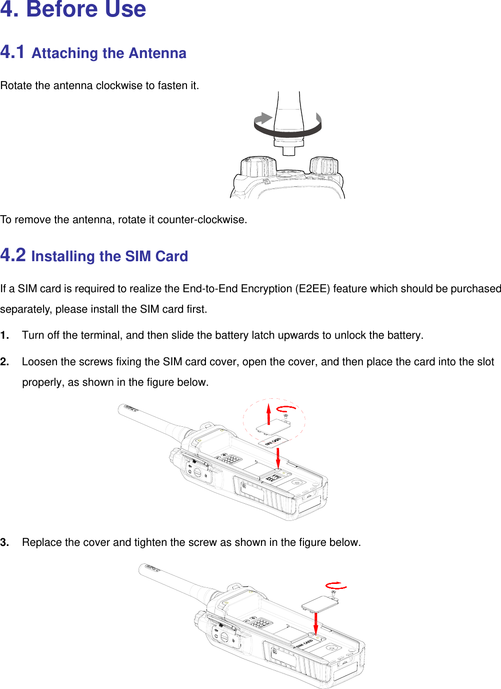
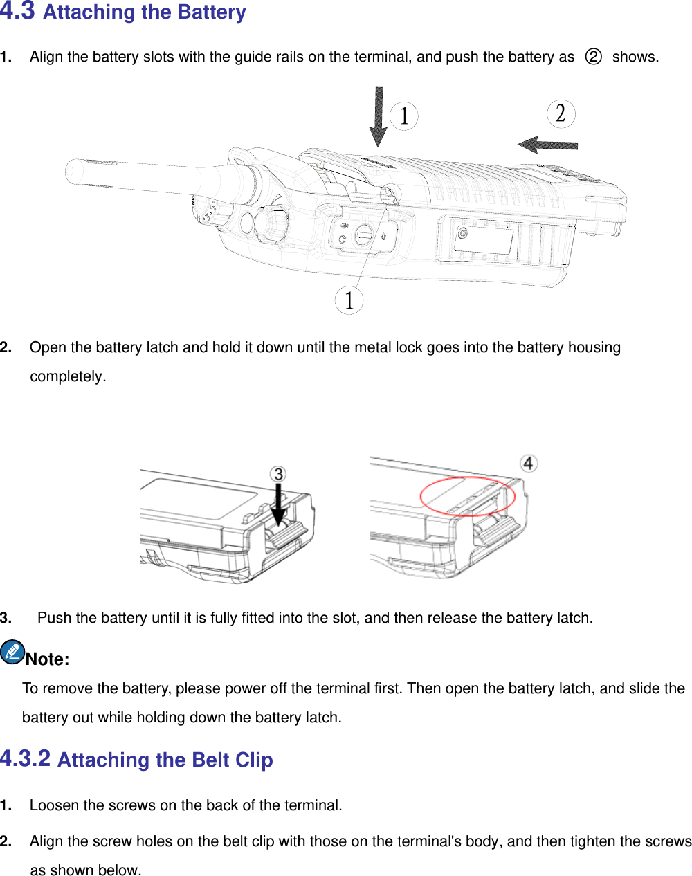
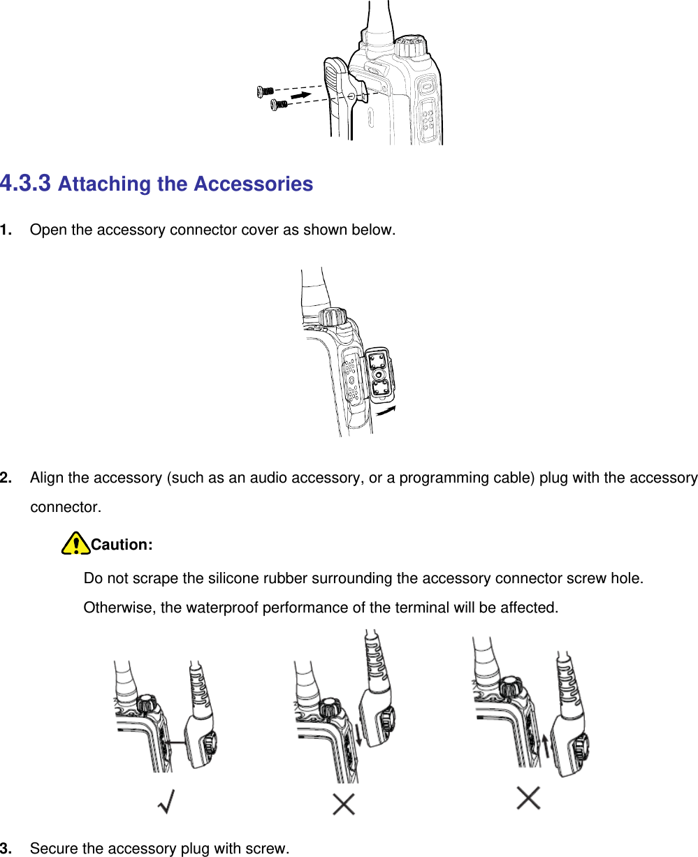
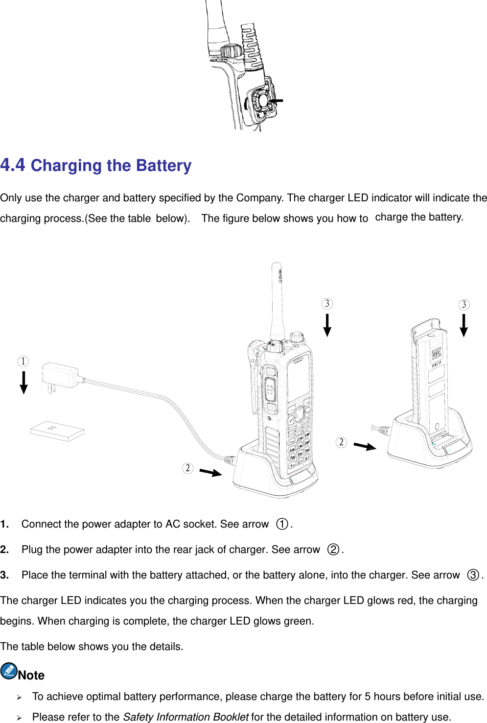
User Manual
Discussion / Help
Navigation