Hytera Communications PT790EXF5 Ex Digital Radio User Manual
Hytera Communications Corporation Ltd. Ex Digital Radio
User Manual
PT790Ex F5 TETRA Intrinsically
Preface
Thanks for your favor in our product. This manual is helpful for you to quickly know how to use the
product. For detailed features and operations, please refer to the TETRA Terminal Series Feature Book
and the Safety Information Booklet along with the product.
This manual is applicable to the following product:
Safe Portable Terminal
Disclaimer
Hytera Communications Corporation Limited (the Company) endeavors to achieve the accuracy and
completeness of this manual, but no warranty of accuracy or reliability is given. All the specifications and
designs are subject to change without notice due to continuous technology development. No part of this
manual may be copied, modified, translated, or distributed in any manner without the express written
permission of us.
We do not guarantee, for any particular purpose, the accuracy, validity, timeliness, legitimacy or
completeness of the Third Party products and contents involved in this manual.
If you have any suggestion or would like to learn more details, please visit our website
at:http://www.hytera.com.
RF Radiation Information
This product must be restricted to operations in an occupational/controlled RF exposure environments.
Users must be fully aware of the hazards of the exposure and able to exercise control over their RF
exposure to qualify for the higher exposure limits.
RF Radiation Profile
Radio Frequency (RF) is a frequency of electromagnetic radiation in the range at which radio signals are
transmitted. RF technology is widely used in communication, medicine, food processing and other fields.
It may generate radiation during use.
RF Radiation Safety
In order to ensure user health, experts from relevant industries including science, engineering, medicine
and health work with international organizations to develop standards for safe exposure to RF radiation.
These standards consist of:
z United States Federal Communications Commission, Code of Federal Regulations; 47 CFR part 2
sub-part J;
z American National Standards Institute (ANSI)/Institute of Electrical and Electronic Engineers (IEEE)
C95. 1-1992;
z Institute of Electrical and Electronic Engineers (IEEE) C95. 1 – 1999;
z International Commission on Non-Ionizing Radiation Protection (ICNIRP) 1998;
FCC Regulations
Federal Communication Commission (FCC) requires that all radio communication products should meet
the requirements set forth in the above standards before they can be marketed in the U.S, and the
manufacturer shall post a RF label on the product to inform users of operational instructions, so as to
enhance their occupational health against exposure to RF energy.
EU Regulatory Conformance
As certified by the qualified laboratory, the product is in compliance with the essential requirements and
other relevant provisions of the Directive 1999/5/EC. Please note that the above information is
applicable to EU countries only.
FCC Statement
This equipment has been tested and found to comply with the limits for a Class B digital
device, pursuant to part 15 of FCC Rules. These limits are designed to provide
reasonable protection against harmful interference in a residential installation. This
equipment generates and can radiate radio frequency energy and, if not installed and
used in accordance with the instructions, may cause harmful interference to radio
communications. However, there is no guarantee that interference will not occur in a
particular installation. If this equipment does cause harmful interference to radio or
television reception, which can be determined by turning the equipment off and on, the
user is encouraged to try to correct.
The interference by one or more of the following measures:
● Reorient or relocate the receiving antenna. Increase the separation between the
equipment and receiver.
● Connect the equipment into an outlet on a circuit different from that to which the
receiver is connected.
● Consult the dealer or an experienced radio/TV technician for help
Operation is subject to the following two conditions: 1. This device may not cause harmful
interference, and 2. This device must accept any interference received, including
interference that may cause undesired operation.
Note:” Changes or modifications to this unit not expressly approved by the party
responsible for compliance could void the user’s authority to operate the equipment.”
RF Exposure Compliance and Control Guidelines and
Operating Instructions
To control your exposure and ensure compliance with the occupational/controlled
environment exposure limits always adhere to the following procedures.
Guidelines:
• Do not remove the RF Exposure Label from the device.
• User awareness instructions should accompany device when transferred to other users.
• Do not use this device if the operational requirements described herein are not met.
Operating Instructions:
• Transmit no more than the rated duty factor of 50% of the time. To transmit (talk), push
the Push-To-Talk (PTT) button. To receive calls, release the PTT button. Transmitting
50 % of the time, or less, is important because this radio generates measurable RF
energy exposure only when transmitting (in terms of measuring for standards
compliance).
• Hold the radio in a vertical position in front of face with the microphone (and the other
parts of the radio, including the antenna) at least one inch (2.5 cm) away from the nose.
Keeping the radio at the proper distance is important because RF exposures decrease
with distance from the antenna. Antenna should be kept away from eyes.
• When worn on the body, always place the radio in a Hytera’s approved clip, holder,
holster, case, or body harness for this product. Using approved body-worn accessories is
important because the use of Hytera’s or other manufacturer’s non-approved accessories
may result in exposure levels, which exceed the FCC’s occupational/controlled
environment RF exposure limits.
• If you are not using a body-worn accessory and are not using the radio in the intended
use position in front of the face, then ensure the antenna and the radio are kept at least
2.5 cm (one inch) from the body when transmitting. Keeping the radio at the proper
distance is important because RF exposures decrease with increasing distance from the
antenna.
• Use only manufacturer’s name approved supplied or replacement antennas, batteries,
and accessories. Use of non-manufacturer-name approved antennas, batteries, and
accessories may exceed the FCC RF exposure guidelines.
•For a list of Hytera’s approved accessories (see the user manual), or (visit the following
website which lists approved accessories: http: add website address), or(The
manufacturer should include the appropriate bracketed item{s} in the manual.)
• For a list of Hytera’s approved accessories (see the user manual), or (visit the following
website which lists approved accessories: www.hytera.cn
IC statement
The device has been tested and compliance with SAR limits, users can obtain Canadian
information on RF exposure and compliance
Après examen de ce matériel aux conformité aux limites DAS et/ou aux limites d’intensité
de champ RF, les utilisateurs peuvent sur l’exposition aux radiofréquences et la
conformité and compliance d’acquérir les informations correspondantes
ThisdevicecomplieswithIndustryCanadalicence‐exemptRSSstandard(s).Operationissubject
tothefollowingtwoconditions:(1)thisdevicemaynotcauseinterference,and(2)thisdevice
mustacceptanyinterference,includinginterferencethatmaycauseundesiredoperationofthe
device.
LeprésentappareilestconformeauxCNRd'IndustrieCanadaapplicablesauxappareilsradio
exemptsdelicence.
L'exploitationestautoriséeauxdeuxconditionssuivantes:
(1)l'appareilnedoitpasproduiredebrouillage,et
(2)l'utilisateurdel'appareildoitacceptertoutbrouillageradioélectriquesubi,mêmesile
brouillageestsusceptibled'encompromettrelefonctionnement.
UnderIndustryCanadaregulations,thisradiotransmittermayonlyoperateusinganantennaofa
typeandmaximum(orlesser)gainapprovedforthetransmitterbyIndustryCanada.Toreduce
potentialradiointerferencetootherusers,theantennatypeanditsgainshouldbesochosen
that,theequivalentisotropicallyradiatedpower(e.i.r.p.)isnotmorethanthatnecessaryfor
successfulcommunication.
Conformémentàlaréglementationd'IndustrieCanada,leprésentémetteurradiopeut
fonctionneravecuneantenned'untypeetd'ungainmaximal(ouinférieur)approuvépourl'é
metteurparIndustrieCanada.Danslebutderéduirelesrisquesdebrouillageradioélectriqueà
l'intentiondesautresutilisateurs,ilfautchoisirletyped'antenneetsongaindesortequela
puissanceisotroperayonnéeéquivalente(p.i.r.e.)nedépassepasl'intensiténécessaireàl'é
tablissementd'unecommunicationsatisfaisante.
ICRSSwarning
Theterm“IC:”beforethecertification/registrationnumberonlysignifiesthattheIndustry
Canadatechnicalspecificationsweremet.
Leterme"IC:"devantlenumérodecertification/enregistrementsignifieseulementqueles
spécificationstechniquesd'IndustrieCanadaontétérespectées.
Nominalantennaportimpedance/ImpédancenominaleantennePort50ΩICradiation
exposurestatement
Thisradioisintendedforuseinoccupational/controlledapplicationswhereusershavebeen
madeawareofthepotentialrisksforexposureandcanexercisecontrolovertheirexposure.This
productisnotauthorisedforgeneralpopulation,consumerorsimilaruse.Thistransmittermust
notbeco‐locatedoroperatinginconjunctionwithanyotherantennaortransmitter.
Cetteradioaétécon?uepourunusageprofessionneldansunenvironnementcontr?lé,oùles
utilisateurssontpleinementconscientsdudangerpotentieldel’expositionàlaquelleilssont
oumisetpeuventexerceruncontr?lesurcetteexposition.CedispositifradioN’ESTPASautorisé
pourl’ensembledelapopulation,lesconsommateursengénéral,nipouruneutilisationsimilaire.
Cetémetteurnedoitpasêtreco‐localisésoufonctionnerenconjonctionavecuneautreantenne
ouémetteur.CaringforyourproductYourradiodoesnotrequireregularservicing.Caringfor
yourradioasdescribedinthisguidewillhelpmaintaintheproductingoodoperationalcondition.
Contents
1. Intrinsically Safe Terminal Information ............................................................. ..............................1
Equipment marking ............................................................................................................................... 5
No Misoperations .................................................................................................................................. 5
Safety Instructions ................................................................................................................................ 6
Compliance Standards.......................................................................................................................... 6
2. Items in the Package .......................................................................................................................... 9
3. Product Overview ............................................................................................................................. 10
3.1 Product Controls ........................................................................................................................... 10
3.2 Programmable Keys ..................................................................................................................... 11
4. Before Use ........................................................................................................................................ 12
4.1 Attaching the Antenna ................................................................................................................... 12
4.2 Installing the SIM Card .................................................................................................................. 12
4.3 Attaching the Battery ..................................................................................................................... 13
4.4 Charging the Battery ..................................................................................................................... 15
5. Status Indication .............................................................................................................................. 17
5.1 Status Icon .................................................................................................................................... 17
5.2 LED Indicator ................................................................................................................................ 18
6. Basic Operations .............................................................................................................................. 19
6.1 Turning On/Off .............................................................................................................................. 19
6.2 Switching Operation Mode ............................................................................................................ 19
6.3 Adjusting the Call Volume ............................................................................................................. 19
6.4 Inputting through Keypad .............................................................................................................. 19
6.5 Locking/Unlocking the Keypad ...................................................................................................... 19
6.6 PIN Code Security and Changing ................................................................................................. 20
6.7 Managing the Contacts ................................................................................................................. 20
7. Call Services ..................................................................................................................................... 21
7.1 TMO .............................................................................................................................................. 21
7.2 DMO ............................................................................................................................................. 23
8. Message ............................................................................................................................................ 25
8.1 Status Message ............................................................................................................................ 25
8.2 User Message ............................................................................................................................... 25
9. Troubleshooting ............................................................................................................................... 27
10. Care and Cleaning .......................................................................................................................... 29
11. Optional Accessories ..................................................................................................................... 30
12. Appendix ......................................................................................................................................... 31
12.1 SSI & TSI Dialing Rules .............................................................................................................. 31
1. Intrinsically Safe Terminal Information
Equipment marking
FM/CAN
z Class I, Zone 0 AEx/Ex ia IIC T4 Ga
z Class I,II, III Div 1, Group A,B,C,D,E, F, G T120°C
z -30℃≤Ta≤60℃
ATEX
z II 1G Ex ia IIC T4
z II 1D Ex ia IIIC T120°C IP6X
z I M1 Ex ia
IECEx
z Ex ia IIC T4 Ga
z Ex ia IIIC T120°C Da IP6X
z Ex ia I Ma
Certificate Number
z
z
No Misoperations
Stop operating this product and leave the explosive atmosphere immediately when the safety or integrity
of the product is endangered, and deliver it to your local dealer for examination.
These items may endanger the product’s safety or integrity:
z The radio is stored improperly;
z The radio is faulty;
z The radio works with overload;
z The radio’s operational error or threshold value is out of allowed range.
z The radio is damaged during transportation;
z The radio’s housing is obviously damaged or cracked;
z The radio logo or model is hard to be recognized;

Safety Instructions
Caution
To protect you against any property loss, bodily injury or even death, be sure to observe the
following safety instructions:
z Use only the Ex-battery BL1813-Ex or BL2413-Ex specified by the Company. The use of other
batteries may result in Ex-protection (intrinsic safety) failure.
z Charge the battery in a non-hazardous area only with the designated charger.
z Do not remove the battery from the radio in a hazardous area.
z Do not carry any standby battery into a hazardous area.
z Use the accessories specified by the Company only. Do not replace the accessories in a hazardous
area.
z Do not use a damaged antenna. If a damaged antenna comes into contact with your skin, a minor
burn may result.
z Do not expose the radio to direct sunlight for a long time, nor place it close to a heating source.
z Hold the radio upright and keep its microphone 2.5 to 5 centimeters away from your mouth during
use.
z If you wear a radio on your body, ensure its antenna is at least 2.5 centimeters away from your body
during transmission.
z Please do not use the radio out of the operating temperature range specification of this product.
z Do not attempt to repair and service the radio, batteries and its accessories. Please contact your
dealer for repair and servicing.
z Do not dissemble or redo the radio. Unauthorized modification of the radio may result in termination
of Ex-protection (intrinsic safety) of the radio.
z Improper usage of the product other than it is intended to be used for will impair safety of the product,
yourself and surrounding environment.
Compliance Standards
Standard Issue Date
FM
FM Class 3600 2011

Standard Issue Date
FM Class 3611 2004
FM Class 3810 2005
ANSI/IEC-60529(Ed. 4.0) 2004
ANSI/ISA-60079-0(12.00.01) 2009
ANSI/ISA-60079-11(12.02.01) 2012
ANSI/ISA-60079-31(12.10.03) 2009
ANSI/ISA-61010-1(82.02.01) 2004
CAN
CAN/CSA-C22.2 No.0-M91 2006
CAN/CSA-C22.2 No.142-M1987 2009
CAN/CSA-C22.2 No.213-M1987 2008
CAN/CSA-C22.2 No.60079-0 (Ed. 5.0) 2011
CAN/CSA-C22.2 No.60079-11 (Ed. 5.0) 2011
CAN/CSA-C22.2 No.60079-31 (Ed.1.0) 2012
CAN/CSA-C22.2 No.60529 (Ed. 5.0) 2005
CAN/CSA-C22.2 No.61010-1 (Ed. 2.0) 2009
ATEX
EN 60079-0 (Ed. 5.0) 2009
EN 60079-11 (Ed. 6.0) 2012
EN 60079-31 (Ed. 1.0) 2009
EN 60529+A1 (Ed. 2.0) 1992
IECEx
IEC-60079-0 (Ed. 6.0) 2011

Standard Issue Date
IEC-60079-11 (Ed. 6.0) 2011
IEC-60079-31 (Ed. 1.0) 2008
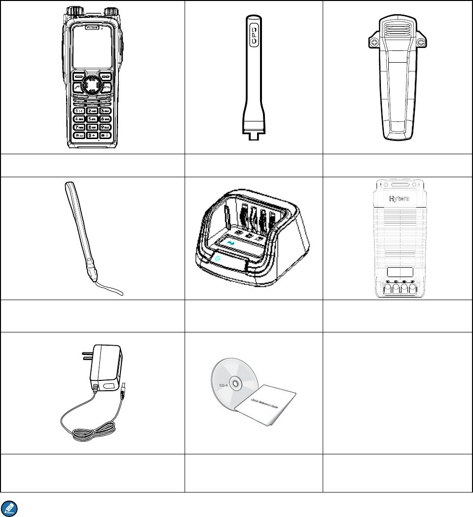
2. Items in the Package
Please unpack carefully and check if all items listed below are received. If any item is missing or
damaged, please contact your dealer.
Portable Terminal Antenna Belt Clip
Strap Charger Battery
Power Adapter Documentation Kit
Note
The frequency band is marked on the label of the antenna; if not, refer to the band on the terminal for
frequency band information.
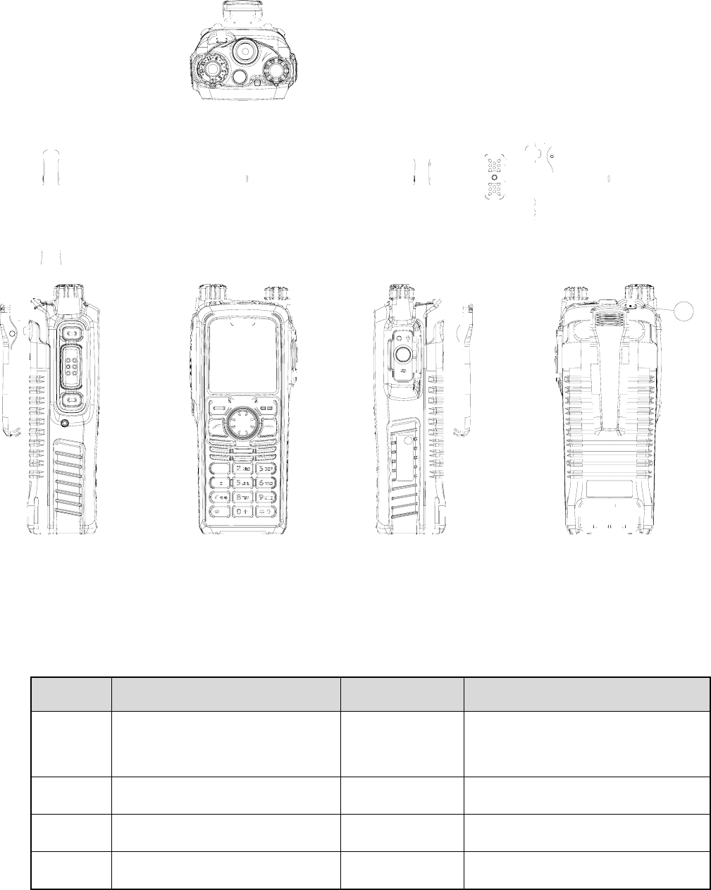
3. Product Overview
3.1 Product Controls
No. Part Name No. Part Name
○
1 SK1 (Side Key 1) ○
15 Power On-Off/Volume Control
Knob
○
2 PTT (Push-to-Talk) Key ○
16 Half-duplex Microphone
○
3 SK2 (Side Key 2) ○
17 Accessory Connector Cover
○
4 Emergency Key ○
18 Options/Back Key
27
No. Part Name No. Part Name
○
5 Group Selector Knob ○
19 End Key
○
6 Full-duplex Receiver ○
20 Navigation Key
○
7 LCD Display ○
21 Full-duplex Microphone
○
8 Func/OK Key ○
22 Battery Latch
○
9 Answer/Call Key ○
23 Accessory Connector
○
10 Half-duplex Speaker ○
24 Belt Clip
○
11 Numeric Keypad ○
25 Battery
○
12 Antenna Connector ○
26 Charging Piece
○
13 LED Indicator ○
27 Strap Hole
○
14 Antenna / /
3.2 Programmable Keys
For enhanced convenience, you may request your dealer to program the SK1, SK2, Navigation key,
Answer/Call key, numeric keys 1–9, and as shortcuts to needed menus and functions.
Please refer to the corresponding TETRA Terminal Series Feature Book for more details.
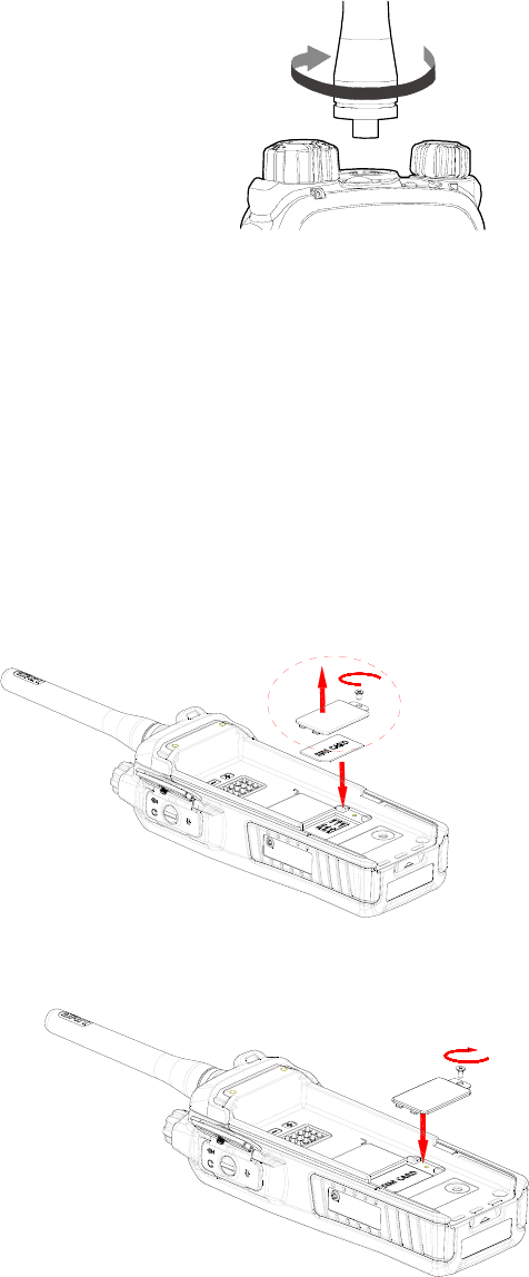
4. Before Use
4.1 Attaching the Antenna
Rotate the antenna clockwise to fasten it.
To remove the antenna, rotate it counter-clockwise.
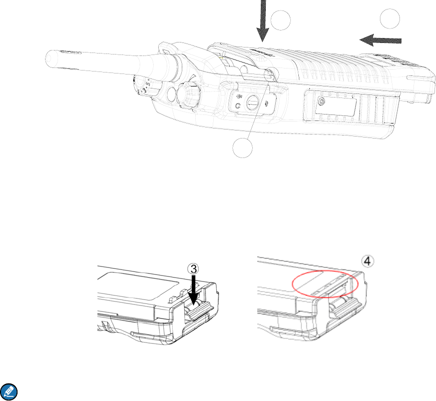
4.2 Installing the SIM Card
If a SIM card is required to realize the End-to-End Encryption (E2EE) feature which should be purchased
separately, please install the SIM card first.
1. Turn off the terminal, and then slide the battery latch upwards to unlock the battery.
2. Loosen the screws fixing the SIM card cover, open the cover, and then place the card into the slot
properly, as shown in the figure below.
3. Replace the cover and tighten the screw as shown in the figure below.
4.3 Attaching the Battery
1. Align the battery slots with the guide rails on the terminal, and push the battery as ○
2 shows.
12
1
2. Open the battery latch and hold it down until the metal lock goes into the battery housing
completely.
3. Push the battery until it is fully fitted into the slot, and then release the battery latch.
Note:
To remove the battery, please power off the terminal first. Then open the battery latch, and slide the
battery out while holding down the battery latch.
4.3.2 Attaching the Belt Clip
1. Loosen the screws on the back of the terminal.
2. Align the screw holes on the belt clip with those on the terminal's body, and then tighten the screws
as shown below.
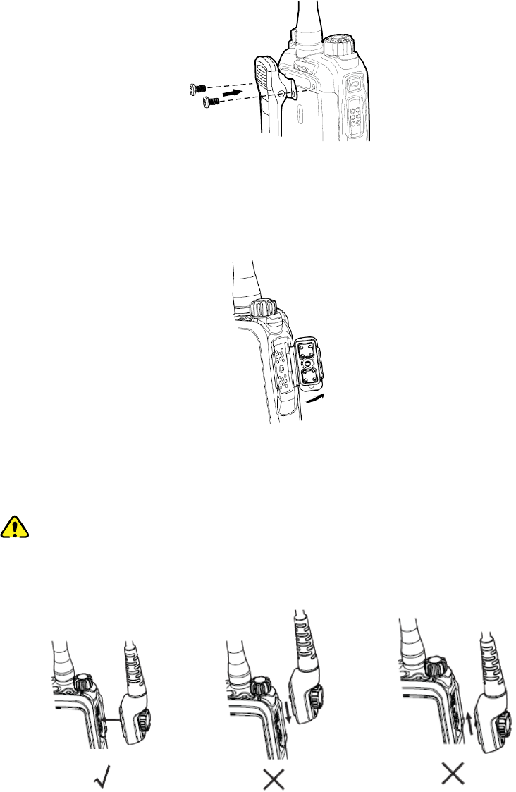
4.3.3 Attaching the Accessories
1. Open the accessory connector cover as shown below.
2. Align the accessory (such as an audio accessory, or a programming cable) plug with the accessory
connector.
Caution:
Do not scrape the silicone rubber surrounding the accessory connector screw hole.
Otherwise, the waterproof performance of the terminal will be affected.
3. Secure the accessory plug with screw.
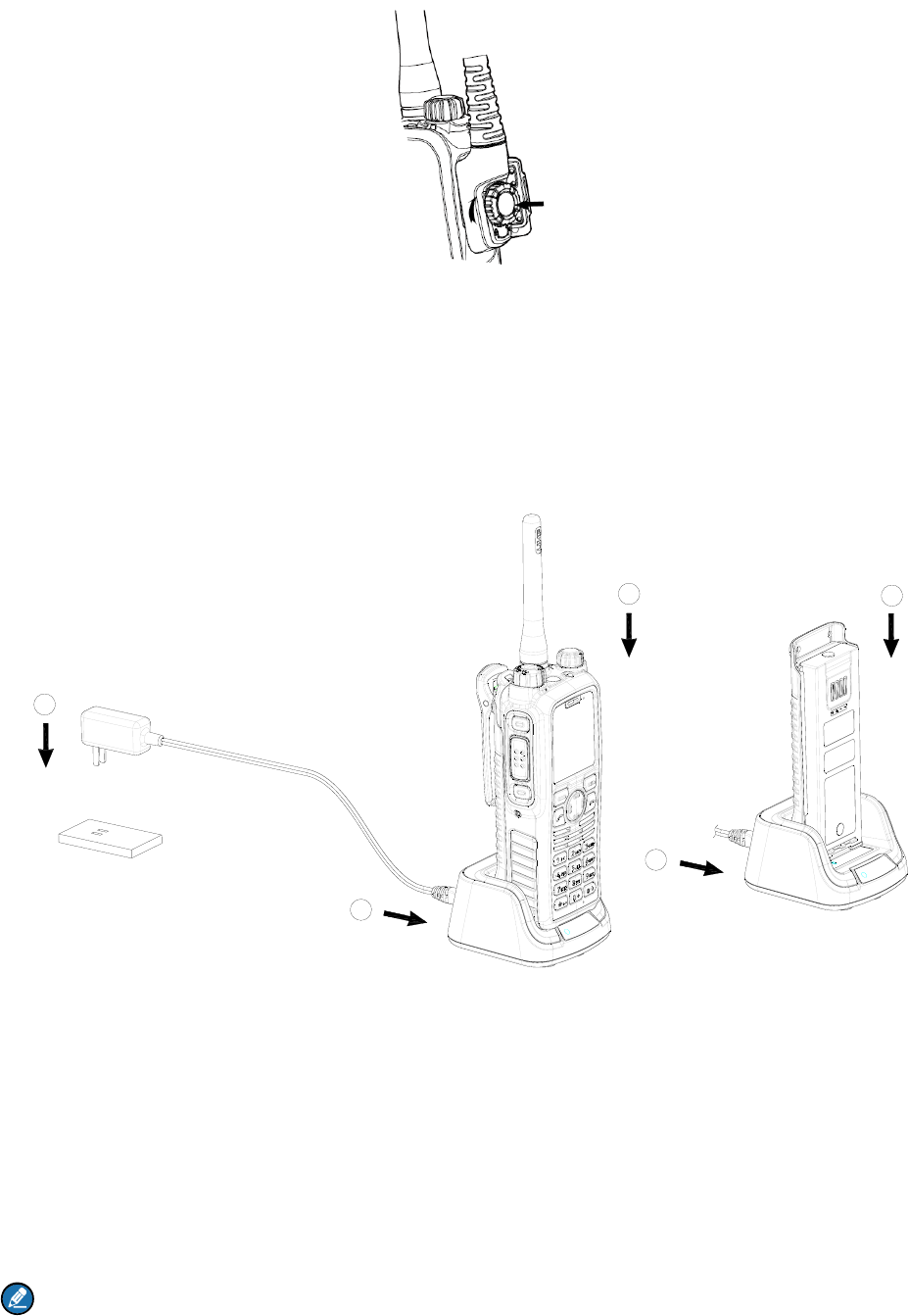
4.4 Charging the Battery
Only use the charger and battery specified by the Company. The charger LED indicator will indicate the
charging process.(See the table below). The figure below shows you how to charge the battery.
1
2
2
3
3
1. Connect the power adapter to AC socket. See arrow ○
1.
2. Plug the power adapter into the rear jack of charger. See arrow ○
2.
3. Place the terminal with the battery attached, or the battery alone, into the charger. See arrow ○
3.
The charger LED indicates you the charging process. When the charger LED glows red, the charging
begins. When charging is complete, the charger LED glows green.
The table below shows you the details.
Note
¾ To achieve optimal battery performance, please charge the battery for 5 hours before initial use.
¾ Please refer to the Safety Information Booklet for the detailed information on battery use.

LED Indication Charging Status
The LED indicator flashes red
slowly. Standby(no load)
The LED indicator glows red. Charging
The LED indicator glows orange. 90% charged
The LED indicator glows green. Fully charged
The LED indicator flashes red
rapidly. Charging failed
5. Status Indication
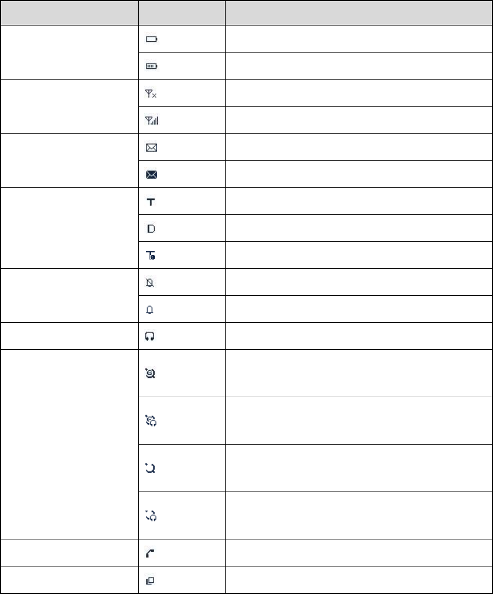
5.1 Status Icon
Name Icon Terminal Status
Battery Strength Icon
The battery strength is low.
More bars indicate more battery strength.
RSSI Icon (For TMO only)
No signal indicates that the terminal is unregistered.
More bars indicate stronger signal.
Message Icon
There is(are) unread message(s).
The Inbox is full.
Operation Mode Icon
The terminal is operating in TMO.
The terminal is operating in DMO.
The terminal is operating in fallback mode.
Profile Icon
Silent
Normal
Audio Accessory Icon The audio accessory is connected.
GPS Icon
A GPS module is connected and the valid GPS data is
received.
Valid GPS data can be received, and the audio
accessory has been connected.
A GPS module is connected and no valid GPS data is
received.
No valid GPS data can be received and the audio
accessory has been connected.
Call Icon A call is in progress.
Group Selection Icon The terminal is ready for switching the talkgroup.

5.2 LED Indicator
LED Indication Terminal Status
The LED indicator glows red. Transmitting
The LED indicator glows green. Receiving
The LED indicator flashes green slowly. Channel free in DMO
The LED indicator glows orange. Channel busy in DMO

6. Basic Operations
6.1 Turning On/Off
z To turn on the terminal, rotate the Power On-Off/Volume Control knob clockwise. Then the LED
indicator flashes green, and the terminal shows the power-up screen and sounds power-up alert.
Upon successful powering on, the terminal enters the home screen. In TMO, after being turned on,
the terminal will register with the network. In DMO, the terminal will be ready for use after being
turned on.
z To turn off the terminal, rotate the Power On-Off/Volume Control knob counter-clockwise until a
click is heard.
6.2 Switching Operation Mode
This terminal can operate in either TMO or DMO. To switch the operation mode, press the Func/OK key
in the home screen to enter the “Mode” menu, and then select “TMO” or “DMO”.
6.3 Adjusting the Call Volume
Rotate the Power On-Off/Volume Control knob clockwise to increase the call volume, or
counter-clockwise to decrease the volume. After the adjustment, the terminal will save the settings and
return to the former screen automatically.
6.4 Inputting through Keypad
You can use the numeric keypad to enter user alias and number, edit messages, etc. The terminal
supports these input methods: English and Number. To switch the input method, press the key on
the numeric keypad. In English/Number input method, you can enter special characters and common
punctuations by pressing . Enter "*" by pressing and enter a space by pressing . As
for other language input methods (depending on your customization), operate accordingly.
6.5 Locking/Unlocking the Keypad
To enable the keypad lock, enter the Function menu by pressing the Func/OK key in the home screen,
and then go to “Settings -> Radio -> Keypad -> Auto Lock -> On”. After this feature is enabled, keypad
will get locked automatically when the preset time (preset by the dealer) expires. Then you can press the
OK key and the to unlock the keypad.
Apart from locking the keypad via menu, you can lock the keypad manually by pressing the Func/OK

key and then directly in the home screen.
6.6 PIN Code Security and Changing
PIN code can prevent unidentified user from using your terminal. To enable or disable the PIN Code
feature, enter the Function menu from the home screen by pressing the Func/OK key , and then go to
“Settings -> Function -> Security -> PIN Enable”. Every time you need to change the settings, it is
required to input the PIN code first (default PIN code: 1234, preset by the dealer).
With this feature enabled, you will need to enter the correct PIN code prior to operating the terminal after
turning it on. If you input the wrong code for 3 times (predefined by the dealer) in a row, the terminal will
be locked. Then you will need to enter the correct PUK code (default PUK code: 12345678) to reset the
PIN code.
To change the PIN code, go to “Settings -> Function -> Security -> PIN Edit”, and input the correct
current PIN code prior to changing the code.
6.7 Managing the Contacts
To view the list, press the Func/OK key to enter the Function menu and then go to the “PhoneBook”
menu.
6.7.1 New Contact
Then press the Func/OK key to enter “Options -> New Contact” to add a new contact: enter the contact’s
alias in the editing screen, and press the OK key to enter the “Input No.” screen to input the contact
number. At last, press the OK key again to select the call type (“Private No.”, “PABX” or “PSTN”).
6.7.2 Viewing the Memory Capacity
To add a new contact, you can enter the Function menu by pressing the Func/OK key and go to
"PhoneBook"; then press Func/OK key to enter “Memory”.

7. Call Services
7.1 TMO
7.1.1 Individual Call
In TMO mode, an individual call can be initiated either as a half-duplex call or full-duplex call, which can
be received without pressing any key (Direct Signaling) or by pressing PTT (Hook Signaling). Contact
your dealer for such programming as well as for more details.
Initiating an Individual call
z Via Menu
In the home screen, press Func/OK key to enter the "PhoneBook" or "Call Log" submenu, and select
a contact. Then press PTT key to initiate a half-duplex call, or press to initiate a full-duplex call.
z Via Manual Dial
In the home screen, to initiate a half-duplex individual call, input the number you want to call through
the keypad, and then press PTT key. To initiate a full-duplex individual call, input the number you
want to call through the keypad, and press repeatedly to select the call type "Private No.".
Then press to initiate a full-duplex call.
Note:
¾ Entry of individual numbers must comply with the SSI&TSI dialing rules. See “SSI&TSI Dialing
Rules” in “Appendix” for more details.
¾ Calls will end automatically if the predefined call timer expires.
Answering an Individual Call
z Half-duplex Individual Call
¾ If it is an incoming call with Direct Signaling, there will be an alert tone to inform the called party
that a call is received.
¾ If it is an incoming call with Hook Signaling, the terminal sounds alert and vibrates to inform the
called party that there is an incoming call. And to receive the call, the PTT key or Func/OK key
should be pressed.
To take the talk rights during the call, there are two situations:
1) if you have no pre-emptive priority, hold down PTT key to talk after the talking party stops talking
and releases its PTT key;
2) if you have already been programmed with pre-emptive priority, hold down PTT key to talk at any
time.

z Full-duplex Individual Call
¾ If it is an incoming call with Direct Signaling, there will be an alert tone to inform the called party
that a call is received.
¾ If it is an incoming call with Hook Signaling, the terminal sounds alert and vibrates to inform the
called party that there is an incoming call. And to receive the call, press the PTT key, Func/OK
key or .
After the call is established, both parties can talk at any time, with no need to use any key.
Hanging up/ Rejecting an Individual Call
When initiating the individual call, press or Options/Back key to terminate it. In the presence of an
incoming individual call, press the Options/Back key or to reject it. In the presence of an
individual call, any party can press to terminate it.
7.1.2 Group Call
Initiating a Group call
In the home screen, you can initiate a group call to the default group by pressing PTT key. To call other
groups, please do as follows:
1. In the home screen, rotate the Group Call Selector knob to select a group. Please perform this
step as soon as the icon appears; otherwise, you may fail to select.
2. Press the Func/OK key to confirm your selection.
3. Press PTT to initiate a group call to this group.
Answering a Group Call
You can receive a group call without any operation. To take the talk rights during the call, there are two
situations: 1) if you have no pre-emptive priority, hold down PTT key to talk after the talking party stops
talking and releases the PTT key;
2) if you have already been programmed with pre-emptive priority, hold down PTT key to talk at any time.
Hanging up a Group Call
The calling party can press to exit a group call. And for the called party in a group call, only those
enabled with "Hang Up" feature (programmed by the dealer) can press to exit a group call.
7.1.3 Telephone Call
The telephone call is a full-duplex individual call with Hook signaling. To initiate the call, follow the steps
below. To answer or hang up/reject the call, see the “Individual Call” in “TMO”.

Initiating a Telephone Call
1. Select a gateway.
In the home screen, press Func/OK key and then go to “Settings -> Network -> PSTN GW / PABX
GW”. Select an appropriate gateway, and press Func/OK key to confirm.
2. Input a telephone number.
Return to the home screen. Input a PABX or PSTN number, which is composed of a prefix
(specified by the gateway, please contact the system administrator) and the telephone number of
the target contact.
3. Select a call type.
Select “PABX” or “PSTN” through the Func/OK key with a screen-label .
4. Press to initiate the call.
7.1.4 Emergency Call
Initiating an Emergency Call
Press the Emergency key and you can initiate an emergency call to the predefined contact. Any
individual contact, group contact, default group, PSTN or PABX contact can be predefined as the
emergency contact. There are two levels for emergency call: emergency priority and pre-emptive priority
3, which can be programmed by your dealer. The emergency priority is endowed with the higher
privilege; thus a call with such priority can break any other call with pre-emptive priority 3, as well as calls
with lower priorities.
Answering an Emergency Call
The emergency call is always received automatically. During an emergency call, the calling party can talk
with no need to use any key. If another member needs to talk, he/she should hold down PTT only after
the calling party stops talking and releases the PTT key.
Hanging up an Emergency Call
See the corresponding part of “Individual call” or “Group call” in accordance with the call type of the
predefined contact.
7.2 DMO
7.2.1 Individual Call
In DMO mode, an individual call can be initiated only as a half-duplex call.

Initiating an Individual Call
In the home screen, directly input the number you want to call through the keypad, or press Func/OK
key to enter the “PhoneBook” or “Call Log” submenu, and select a contact. Then press PTT key to
initiate the call.
Note:
Entry of individual numbers must comply with the SSI&TSI dialing rules. See “SSI&TSI Dialing Rules”
in “Appendix” for more details.
Answering an Individual Call
You can receive an individual call in DMO automatically. During the call, you can hold down the PTT key
to talk after the calling party stops talking and releases the PTT key.
Hanging up an Individual Call
The calling party can press to terminate the call. The called party can press to exit the call.
7.2.2 Group Call
Group calls in DMO mode is the same as that in TMO mode. Please refer to operation method described
in”Group Call” in the above “TMO” section.
7.2.3 Emergency Call
In DMO mode, emergency calls are endowed with emergency priority only. Please refer to operation
method described in ”Emergency Call” in the above “TMO” section.

8. Message
8.1 Status Message
Status message, which should be programmed by your dealer only, can facilitate instant messaging of
the frequently-used messages. You can only send or view rather than edit the status messages. When
the message is sent successfully, for the receiving terminal, it will receive either the status ID of the
status message (if the terminal has not predefined the message text) or the predefined text of the status
ID (if the terminal has predefined the message text).
Note:
The "Fixed Status Message" and the "Status Message" are predefined by the dealer via the CPS.
Sending a Status Message
z Press the Func/OK key and go to “Message -> Create Msg -> StatusMsg -> Sel Msg”. Select a
desired status message, and press the Func/OK key to proceed. Choose either an individual or a
group as the target contact, input the appropriate number and press Func/OK to send the message.
z Long press the programmed One Key key to send the preset status message directly.
Viewing the Status Message
When the icon appears in the status bar, it indicates there is/are unread message(s). Do as follows to
view it:
z In the prompt screen for an unread message, press the Func/OK key to enter the Inbox, and press
Func/OK key again to read.
z In the home screen, press the Func/OK key and navigate to “Message -> Inbox -> Inbox”. Then you
can view the unread message.
8.2 User Message
Editing a User Message
Press the Func/OK key and navigate to “Message -> Create Msg -> User Msg”. Press Func/OK key
again to edit a user message.
Sending a User Message
After editing, press Func/OK key to confirm. Then select the target contact and decide whether to send it
as a flash message.

Note:
If the message is sent as a flash message, the receiving party can preview all the content in a
predefined time period without any operation. Once the time period expires, the terminal will go back
to the home screen, with the icon displaying on the status bar.
Viewing the User Message
When the icon appears in the status bar, it indicates there is/are unread message(s). Do as follows
to view it:
z In the prompt screen for an unread message, press the Func/OK key to enter the Inbox, and press
Func/OK key again to read.
z In the home screen, press the Func/OK key and navigate to “Message -> Inbox -> Inbox”. Then you
can view the unread message.

9. Troubleshooting
Phenomenon Analysis Solution
Terminals cannot be
powered on.
The battery power gets too low to
power on the terminal. Charge for the battery.
Network registration
fails or
network cannot be
found.
The terminal may be operating in
DMO. Switch to TMO mode.
The terminal may get out of the
network coverage (in TMO mode).
Check the signal strength. Make
sure the terminal is within the
network coverage.
The terminal may not be granted
network access.
Contact the network operator for the
terminal authorization.
Calls cannot be
initiated.
The terminal or the called party may
not be within the network coverage.
Check the signal strength. Make
sure the terminal is within the
network coverage.
The terminal may operate in an
improper mode.
Check the operation mode. Make
sure the terminal works in the right
mode.
A certain group call
cannot be initiated or
received.
The terminal may not be a member of
the group.
Check whether the terminal is a
member of the group. If not, contact
your dealer to add the terminal to the
group.
The terminal may not be authorized to
access the target group.
Contact the network operator for the
terminal authorization.
Calls are always
interrupted.
The current channel is assigned to
emergency calls or other calls with
higher priority.
Wait until the channel becomes
available and try again.
A half-duplex call can
not be established.
The predefined time period for
establishing a call may expire.
Make sure the call is established
within the predefined time period.
The channel may be occupied by Wait until the channel becomes

Phenomenon Analysis Solution
another terminal with higher call
priority.
available and try again.
The channel resources may be
allocated to other services due to
overloaded network.
Wait until the channel becomes
available and try again.
Abnormal
disconnection occurs
during a call.
The terminal may get out of the
network coverage (in TMO mode).
Check the signal strength. Make
sure the terminal is within the
network coverage.
The terminal might operate at an
unfavorable position where
communication may be blocked by
high buildings or frustrated in the
underground areas (in DMO mode).
Move to an open and flat area, and
restart the terminal.
As for the same
status message, the
content displayed at
the receiving party is
different from that of
the sending party .
The parties have associated the
same status message ID with
different contents.
Make sure the status message ID is
associated with the same content.
If the above solutions cannot fix your problems, or you may have some other queries, please contact us
or your local dealer for more technical support.

10. Care and Cleaning
To guarantee optimal performance as well as a long service life of the product, please follow the tips
below.
Product Care
z Do not pierce or scrape the product.
z Keep the product far away from substances that can corrode the circuit.
z Do not hold the product by its antenna or earpiece cable directly.
z Attach the accessory connector cover when the product is not in use.
Product Cleaning
Caution: Turn off the product and remove the battery before cleaning.
z Clean up the dust and fine particles on the product surface and charging piece with a clean and dry
lint-free cloth or a brush regularly.
z Use neutral cleanser and a non-woven fabric to clean the keys, control knobs and front case after
long-time use. Do not use chemical preparations such as stain removers, alcohol, sprays or oil
preparations, so as to avoid surface case damage.
z Make sure the product is completely dry before use.

11. Optional Accessories
The following items are the main optional accessories for the product. For more other accessories,
please consult your local dealer.
Caution: Use the accessories specified by the Company only. If not, the Company shall not be
liable for any loss or damage arising out of use of unauthorized accessories.
z Power Supply:
MCA05 Battery Optimizing System,
MCA08 MCU Multi-unit Rapid-rate Charger (for Li-Ion/Ni-MH Battery),
CH10A06 Dual-pocket MCU Multi-unit Rapid-rate Charger (for Li-Ion/Ni-MH Battery),
CHV09 Vehicle Adapter for Charger
z Audio Accessory:
SM18N8-Ex Remote Speaker Microphone (IP67)
EHN12-Ex Swivel Earset with on-MIC PPT
z Cable:
PC67 Programming Cable (USB Port)
z Carrying Accessories:
LCY005 Leather Carrying Case for thin battery (swivel)
12. Appendix
12.1 SSI & TSI Dialing Rules
In the TETRA system, subscribers are distinguished by different identities. Each subscriber is assigned
with a unique short subscriber identity (SSI), which serves a part of the TETRA subscriber identity (TSI).
And TSI is generally composed in this way: Mobile Country Code (MCC) + Mobile Network Code (MNC)
+ SSI. To initiate an individual call, please dial the SSI or TSI in compliance with the rules below.
z SSI Dialing: Make sure there are not more than 8 digits.
z TSI Dialing
¾ MNC+SSI: 1) Input the MNC as it is; 2) SSI must be 8 digits long. Add 0 before the first digit of
SSI which is shorter than 8 digits. For example, when MNC is 20 and SSI is 504, you need to
input 2000000504.
¾ MCC+MNC+SSI: 1) MCC must contain 3 digits. Add 0 before the first digit of MCC which is
shorter than 3 digits; 2) MNC must contain 4 or 5 digits. When the MNC is shorter than 4 digits,
add 0 before its first digit; when it is 5 digits long, use it directly; 3) SSI must be 8 digits long. Add 0
before the first digit of SSI which is shorter than 8 digits. For example, when MCC is 460, MNC is
20 and SSI is 504, you need to input 460002000000504.