Hytera Communications RD106XU1 Digital Repeater User Manual
Hytera Communications Corporation Limited Digital Repeater
User manual
Preface
Welcome to the world of Hytera and thank you for purchasing this product. This manual includes a
description of the functions and step-by-step procedures for use. To avoid bodily injury or property loss
caused by incorrect operation, please carefully read the Safety Information Booklet before use.
This manual is applicable to the following product:
RD106X Digital Repeater (X may represent 2, 5, 6 or 8)
Copyright Information
Hytera is the trademark or registered trademark of Hytera Communications Corporation Limited (the
Company) in PRC and/or other countries or areas. The Company retains the ownership of its trademarks
and product names. All other trademarks and/or product names that may be used in this manual are
properties of their respective owners.
The product described in this manual may include the Company’s computer programs stored in memory or
other media. Laws in PRC and/or other countries or areas protect the exclusive rights of the Company with
respect to its computer programs. The purchase of this product shall not be deemed to grant, either directly
or by implication, any rights to the purchaser regarding the Company’s computer programs. Any of the
Company’s computer programs may not be copied, modified, distributed, decompiled, or
reverse-engineered in any manner without the prior written consent of the Company.
Disclaimer
The Company endeavors to achieve the accuracy and completeness of this manual, but no warranty of
accuracy or reliability is given. All the specifications and designs are subject to change without notice due
to continuous technology development. No part of this manual may be copied, modified, translated, or
distributed in any manner without the express written permission of us.
We do not guarantee, for any particular purpose, the accuracy, validity, timeliness, legitimacy or
completeness of the Third Party products and contents involved in this manual.
If you have any suggestions or would like to learn more details, please visit our website at:
http://www.hytera.com.
RF Radiation Information
This product must be restricted to operations in an Occupational/Controlled RF exposure Environments.
Users must be fully aware of the hazards of the exposure and able to exercise control over their RF
exposure to qualify for the higher exposure limits.
RF Radiation Profile
Radio Frequency (RF) is a frequency of electromagnetic radiation in the range at which radio signals are
transmitted. RF technology is widely used in communication, medicine, food processing and other fields. It
may generate radiation during use.
RF Radiation Safety
In order to ensure user health, experts from relevant industries including science, engineering, medicine
and health work with international organizations to develop standards for safe exposure to RF radiation.
These standards consist of:
United States Federal Communications Commission, Code of Federal Regulations; 47 CFR § 1.1307,
1.1310 and 2.1091
American National Standards Institute (ANSI) / Institute of Electrical and Electronic Engineers (IEEE)
C95. 1:2005; Canada RSS102 Issue 5 March 2015
Institute of Electrical and Electronic Engineers (IEEE) C95.1:2005 Edition
FCC Statement
This equipment has been tested and found to comply with the limits for a Class B digital device, pursuant to
part 15 of FCC Rules. These limits are designed to provide reasonable protection against harmful
interference in a residential installation. This equipment generates and can radiate radio frequency energy.
If not installed and used in accordance with the instructions, it may cause harmful interference to radio
communications. However, there is no guarantee that interference will not occur in a particular installation.
Verification of harmful interference by this equipment to radio or television reception can be determined by
turning it off and then on. The user is encouraged to try to correct the interference by one or more of the
following measures:
Reorient or relocate the receiving antenna. Increase the separation between the equipment and
receiver.
Connect the equipment into an outlet on a different circuit to that of the receiver's outlet.
Consult the dealer or an experienced radio/TV technician for help.
Operation is subject to the following two conditions:
This device may not cause harmful interference.
This device must accept any interference received, including interference that may cause undesired
operation.
Note: Changes or modifications to this unit not expressly approved by the party responsible for compliance
could void the user's authority to operate the equipment.
FCC Regulations
Federal Communication Commission (FCC) requires that all radio communication products should meet
the requirements set forth in the above standards before they can be marketed in the U.S, and the
manufacturer shall post a RF label on the product to inform users of operational instructions, so as to
enhance their occupational health against exposure to RF energy.
Operational Instructions and Training Guidelines
To ensure optimal performance and compliance with the occupational/controlled environment RF energy
exposure limits in the above standards and guidelines, users should always adhere to the followings:
Gain of antenna must not exceed 10dBi (Outdoor) or 5dBi (Indoor).
Antenna Installation: install the antenna at least 150cm (Outdoor) or 85cm (Indoor) away from your
body, in accordance with the requirements of the antenna manufacturer/supplier.
ISEDC Statement
This device complies with Innovation, Science and Economic Development Canada Compliance
license-exempt RSS standard(s). Operation is subject to the following two conditions:
This device may not cause harmful interference.
This device must accept any interference received, including interference that may cause undesired
operation.
Le présent appareil est conforme aux CNR d'ISEDC applicables aux appareils radio exempts de licence.
L'exploitation est autorisée aux deux conditions suivantes: (1) l'appareil ne doit pas produire de brouillage,
et (2) l'utilisateur de l'appareil doit accepter tout brouillage radioélectrique subi, même si le brouillage est
susceptible d'en compromettre le fonctionnement
ISEDC Radiation Exposure Statement:
This device must be restricted to work related operations in an Occupational/Controlled RF exposure
Environment.
This equipment should be installed and operated with minimum distance 150cm (Outdoor) or 85cm (Indoor)
between the antenna & your body.
ISEDC exposition aux radiations:
Ce dispositif doit être limité aux opérations liées au travail dans un environnement d'exposition RF
professionnel/contrôlé.
Cet équipement doit être installé et utilisé avec un minimum de 150cm (extérieur) or 85cm (intérieur) de
distance entre le antenne et votre corps.
EU Regulatory Conformance
As certified by the qualified laboratory, the product is in compliance with the essential requirements and
other relevant provisions of 2014/53/EU.
Please note that the above information is applicable to EU countries only.
Documentation Information
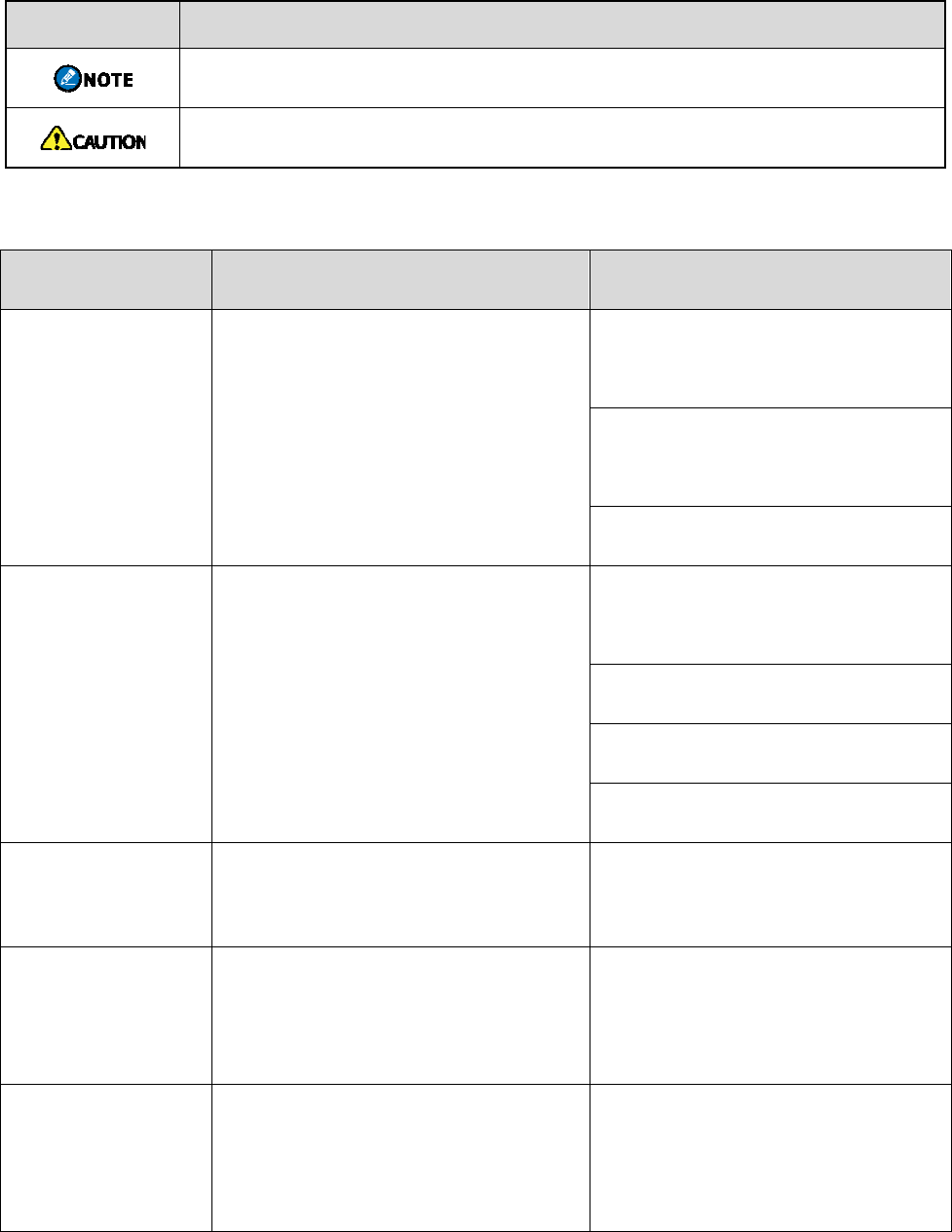
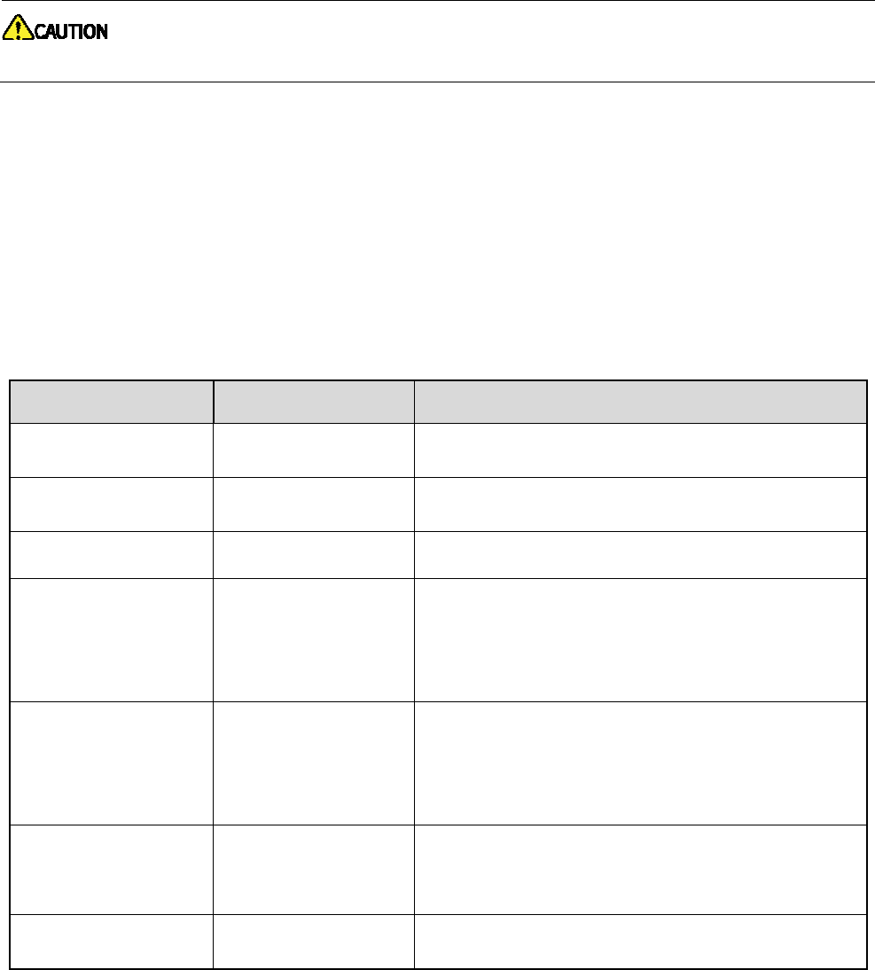
Icon Conventions
Icon Description
Indicates references that can further describe the related topics.
Indicates situations that could cause data loss or equipment damage.
Notational Conventions
Item Description Example
Boldface
Denotes menus, tabs, parameter
names, window names, dialogue
names, and hardware buttons.
To save the configuration, click
Apply.
The Log Level Settings dialogue
appears.
Press the PTT key.
" "
Denotes messages, directories, file
names, folder names, and parameter
values.
The screen displays "Invalid
Battery!".
Open "PDT_PSS.exe".
Go to "D:/opt/local".
In the Port text box, enter "22".
> Directs you to access a multi-level
menu. Go to File > New.
Italic Denotes document titles.
For details about using the DWS,
refer to Dispatch Workstation User
Guide.
Courier New Denotes commands and their
execution results.
To set the IP address, run the
following command:
vos-cmd - m name IP
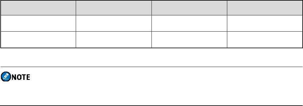
1. Packing List
Please unpack carefully and check that you have received the following items. If any item is missing or
damaged, please contact your dealer.
Item Quantity (PCS) Item Quantity (PCS)
Repeater 1 Documentation Kit 1
Power Cord 1 / /
Figures in this manual are for reference only.
Check the main unit label to ensure that the purchased product is correct.
2. Product Overview
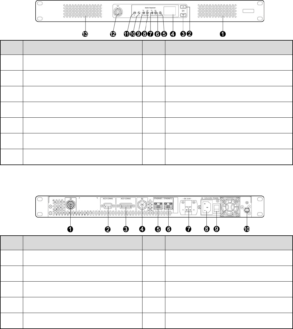
2.1 Front Panel
No. Part Name No. Part Name
1 Air Inlet for PA 8 Timeslot A RX Indicator
2 Channel Up Key 9 Timeslot A TX Indicator
3 Channel Down Key 10 Analog Mode Indicator
4 Seven-segment Display 11 Digital Mode Indicator
5 Alarm Indicator 12 Audio/Programming Connector
6 Timeslot B RX Indicator 13 Air Inlet for Power Supply
7 Timeslot B TX Indicator / /
2.2 Rear Panel
No. Part Name No. Part Name
1 TX Antenna Connector 6 Ethernet Port 2
2 Monitor/Tuning Interface 7 DC Power Inlet
3 Accessory Jack 8 AC Power Inlet
4 RX Antenna Connector 9 AC Power Switch
5 Ethernet Port 1 10 Ground Screw
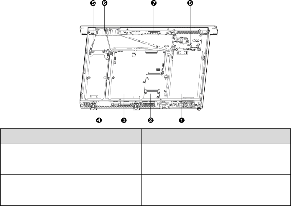
2.3 Internal Parts
No. Part Name No. Part Name
1 Power Supply Module 5 Wind Scooper
2 Network Board 6 Fan
3 Baseband Module 7 Control Panel
4 PA Module 8 Floating Charge Board

3. Installation
To ensure optimum performance and reliability of the repeater, install it properly according to the following
instructions.
3.1 Installation Requirements
Installation Environment
The repeater must be installed in a dry and well-ventilated place. The ambient temperature ranges from
-30°C to +60°C, and the relative humidity is 95%.
Installation Location
The repeater can be installed in a rack, bracket and cabinet or on a desk.
For more information, refer to the Safety Information Booklet.
3.2 Pre-installation Tasks
Preparing the tools
Phillips screwdriver
T-10 torx screwdriver
Spanner
Anti-static gloves
Multimeter
Checking the power supply
Before installing the repeater, make sure that the power supply meets the following requirements:
DC power voltage: 13.6±15% V
AC power voltage: 100~240V
3.3 Installation Procedure
To install the repeater, do as follows:

1. Wear the anti-static gloves.
2. Place the repeater to a proper location.
3. Connect accessories including the antenna, feed lines, and power cords to the repeater.
The antenna and feed lines need to be purchased separately.
4. Ground the repeater through the Ground Screw located on the rear panel.
3.4 Post-installation Check
To check whether the repeater works properly, do as follows:
1. Turn the repeater on.
2. Observe the LED indicators and the display in the front panel.
If the Timeslot A RX indicator glows yellow and the display shows the current channel, the
repeater works properly.
If the Alarm Indicator glows red and the display shows the alarm code, the repeater does not work
properly.
4. Basic Operations
4.1 Turning the Repeater On or Off
If the repeater is connected to a DC power supply, press the power switch on the DC power supply to turn
the repeater on or off.
If the repeater is connected to an AC power supply, press the AC Power Switch located in the rear panel
to turn the repeater on or off.
Do not touch the metal on the side of the repeater for more than 1 second during normal use.
4.2 Switching the Channel
You can use the Channel Up or Channel Down key in the front panel to change the channel. After you
change the channel, the current channel number appears on the display of the repeater.
To switch to the previous or next channel, press the Channel Up or Channel Down key.
4.3 Checking LED Indications
Indicator Color Description
Digital Mode Blue The repeater is operating in digital mode.
Analog Mode Yellow The repeater is operating in analog mode.
Alarm Red The repeater is not working properly.
Timeslot A TX Red
Analog mode: The repeater is transmitting.
Digital mode: The repeater is transmitting in
timeslot A.
Timeslot A RX Green
Analog mode: The repeater is receiving.
Digital mode: The repeater is receiving in
timeslot A.
Timeslot B TX Red Digital mode: The repeater is transmitting in timeslot
B.
Timeslot B RX Green Digital mode: The repeater is receiving in timeslot B.
5. Alarm Information
With the Alarm feature enabled by your dealer, the repeater can detect alarms. When an error occurs, the
display shows the alarm code with the Alarm Indicator on the front panel glowing red.
5.1 Low Forward Power Alarm
Description
When the forward power is below the preset value, the Alarm Indicator glows red and the display shows
the alarm code E8.
Then the repeater may continue or stop the transmission.
Solution
Check if the connection between the repeater and RF adapter cable or antenna/feed line is loose or
damaged.
If yes, secure or replace the cable or antenna/feed line.
If no, contact your local dealer for technical support.
5.2 TX/RX Unlock Alarm
Description
When the TX PLL or RX PLL is unlocked, the Alarm Indicator glows red and the display shows the alarm
code E4 or E5 respectively.
Then certain features of the repeater become unavailable automatically.
Solution
Disconnect the power supply, and then open the housing to check if the hardware cable is loose or
damaged.
If yes, secure or replace the cable.
If no, contact your local dealer for technical support.

5.3 Over Temperature Alarm
Description
When the temperature of the PA module exceeds the upper threshold, the Alarm Indicator glows red and
the display shows the alarm code E6.
Then the repeater will stop transmission.
Solution
1. Check whether the temperature of the PA module surface is over 120 C.
If yes, proceed with Step 2.
If no, proceed with Step 3.
Do not touch the surface of the PA module to avoid burn. You can use a digital thermometer
with thermocouple to measure the temperature.
2. Check whether the ambient temperature and ventilation conditions of the repeater satisfy the foregoing
installation requirements.
If yes, proceed with Step 3.
If no, make improvements as soon as possible by mounting air conditioning equipment, improving
equipment ventilation, or reducing ambient temperature.
3. Check if the connection between the repeater and RF cable or antenna/feed line is loose or damaged.
If yes, secure or replace the cable or antenna/feed line.
If no, contact your local dealer for technical support.
5.4 Over/Low Voltage Alarm
Description
When the repeater detects that the voltage inputted by the external power supply is out of the normal range
(11.56–15.64 V), the Alarm Indicator glows red and the display shows the alarm code EH (over voltage) or
E3 (low voltage).
Then the repeater will automatically stop working.
Solution
1. Use voltmeter to check whether the DC or AC power voltage is too low or too high.
If yes, replace the DC or AC power supply.
If no, proceed with Step 2.
2. Check whether the power cord is loose or damaged.
If yes, secure or replace the power cord.
If no, contact your local dealer for technical support.
5.5 Voltage Standing Wave Ratio (VSWR) Alarm
Description
When the repeater detects the VSWR of the TX antenna for the PA module exceeds the normal value, the
Alarm Indicator glows red and the display shows the alarm code E7.
Then the repeater will automatically work at low TX power.
Solution
1. Check if the TX frequency is within the frequency range of the antenna.
If yes, proceed with Step 2.
If no, contact your local dealer to replace the antenna.
2. Check if the connection between the repeater and RF adapter cable or antenna/feed line is loose or
damaged.
If yes, replace the cable or antenna/feed line.
If no, contact your local dealer for technical support.

6. Troubleshooting
Phenomena Analysis Solution
Power-on Failure
The power cord may be unconnected or not
securely connected to the outlet.
Properly connect the power cord and
ensure secure connection.
The fuse in the power cord may be
damaged.
Check if the fuse has blown. If yes,
replace it with a new one.
Group members
cannot talk to
each other, or
the repeater
cannot
communicate
with a radio.
The TX/RX frequency of the repeater is
inconsistent with that of the radio.
Check if the frequencies are
consistent. Reset them when
necessary.
The repeater fails to transit useful signal
due to strong interference signal.
Remove or bypass the interference
source, or change to operate at other
frequencies.
The group member is out of the coverage
of the repeater.
Go within the coverage of the
repeater.
Group members
cannot talk to
each other, even
though RX
indication is
given.
The radio ID is inconsistent with that of the
other group members.
Set the radio ID to the same as that of
the other members.
The CTCSS/CDCSS of the radio is
inconsistent with that of the repeater.
Check if the CTCSS/CDCSSs are
consistent, Reset the
CTCSS/CDCSSs when necessary.
Short
communication
range or poor
audio.
The connection cable is damaged, and the
signal energy leaks.
Check the damages, and replace the
cable with a new one if necessary.
The antenna connector and the cable may
get loose connection or even disconnected.
Check and secure the cable
connector, or replace it if necessary.
Invisible damage may occur to the cable. Replace the cable with a new one.
If the above solutions cannot fix your problems, or you may have some other queries, please contact us or
your local dealer for more technical support.

7. Care and Cleaning
To guarantee optimum performance as well as a long service life of the product, please follow the tips
below.
7.1 Product Care
Keep the product at a place of good ventilation and heat dissipation to facilitate normal work.
Do not place irrelevant articles on top of the product to ensure optimal heat dissipation.
Do not pierce or scrape the product.
Keep the product away from substances that can corrode the circuitry.
Do not place the product in corrosive agents, solutions or water.
7.2 Product Cleaning
Be sure to power off the product before cleaning.
Remove the dust and fine particles on the repeater surface with a clean and dry lint-free cloth or a
brush regularly.
Use a non-woven fabric with neutral cleanser to clean the keys, control knobs, LCD and connectors
after long-time use. Do not use chemical preparations such as stain removers, alcohol, sprays or oil
preparations.
Make sure the product is completely dry before use.

8. Optional Accessories
Use the accessories specified by the Company only. If not, Hytera shall not be liable for any losses or
damages arising out of use of unauthorized accessories.
For more information of the main optional accessories for the repeater, please consult your local dealer.