Hytronik Electronics HC418VRF Lighting Control Switch User Manual of HC418V RF HC424RF
Hytronik Electronics Co., Ltd Lighting Control Switch of HC418V RF HC424RF
User Manual
120~277VAC 60Hz.
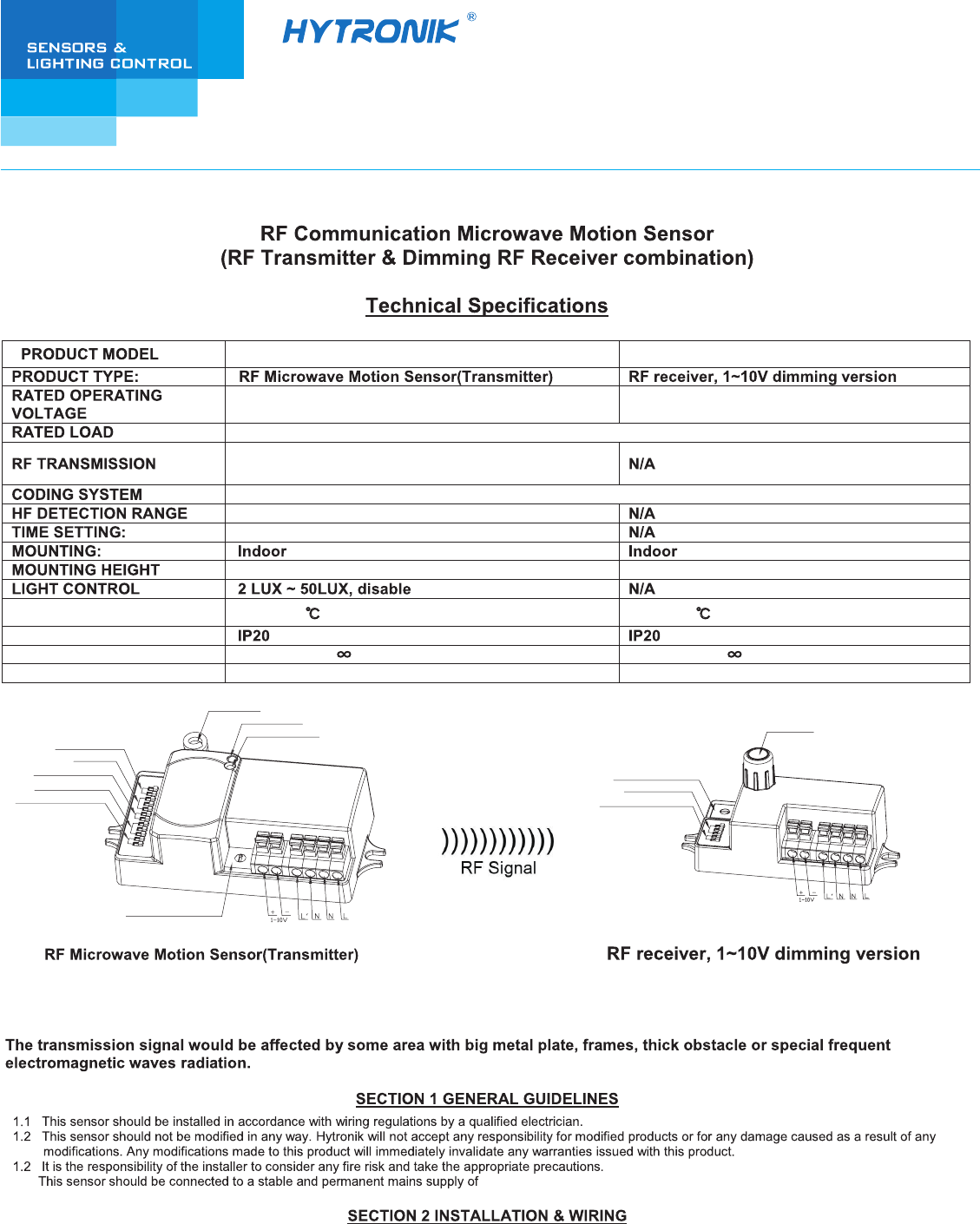
Model NO.:HC418V/RF Model NO.:HC424RF
RF antenna
Rotary coding switch
Stand-by period
Stand-by dimming level
Detection area
Daylight threshold
Stand-by period
Stand-by dimming level
Hold-time
Rotary coding switch
RF Antenna
LED indication
Daylight sensor
Block A6, Nan’pu Science & Technology Park, Hao’si,
Shajing Street, Bao’an District, Shenzhen, P.R.C. 518104
T: 86 755 27322200 F: 86 755 27308687
E: info@hytronik.com W: www.hytronik.com
HYTRONIK ELECTRONICS CO.,LTD
2.2 Keep the RF antenna at least 3cm away from the driver or ballast.
1.4
2.1 Ensure that the electricity supply is switched off completely before installing or servicing this product.
PROTECTION LEVEL
STANDBY PERIOD
STANDBY DIMMING LEVEL
WORKING TEMPERATURE
HC418V/RF
Up to 30 meters indoor transmission and 100
meters in open area.
Fixed address coding with 10 channels (max. 10 groups)
Diameter Max. 12m
5s~30min
-20 ~ +60℃
0s, 10s~1h, + 0s, 10s~1h, +
10~50% 10~50%
-20 ~ +60℃
Max. 6m Max. 6m
HC424RF
120~277VAC 60Hz 120~277VAC 60Hz
200W@120VAC; 500W@277VAC(capatitive Load)
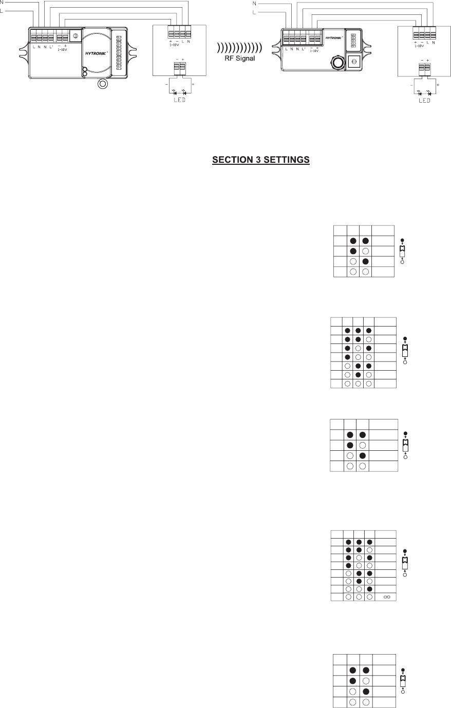
Wring with any 1~10V control gear to achieve dimming function.
HC418V/RF
LED Driver LED Driver
HC424RF
RF wireless communication makes installation easier with no cables connection.The motion at 1 sensor (the master unit) can
be passed onto other pre-defined individuals (the slave units) through RF transmission. This wireless radio wave transmission
can reach 100 meters in open area with internal RF antenna, 30 meters blocked by one wall, 20 meters blocked by two walls.
Settings for HC418V/RF
I – 5S
II – 30S
III – 1 minute
IV – 5 minutes
V – 10 minutes
VI – 20 minutes
VII – 30 minutes
I – Disable
II – 50 lux
III – 10 lux
IV – 2 lux
I – maximum range up to 100%
II – 75%
III – 50%
IV – 10%
I – 0S
II – 10S
III – 1 minute
IV – 5 minutes
V – 10 minutes
VI – 30 minutes
VII – 1 hour
VIII – +
Note: “0s” means on/off control; “+∞” means 2 steps of dimming control, fixture never switch off.
∞ +∞
This is the time period you would like to keep at the low light output level before it is completely switched off in the long absence of people.
Stand-by period (corridor function)
I – 10%
II – 20%
III – 30%
IV – 50%
This is the dimmed low light output level you would like to have after the hold-time in the absence of people.
Stand-by dimming level
100%
75%
50%
10%
1 2
I
II
III
IV
I
II
III
IV
V
VI
VII
1 2 3
5S
30S
1min
5min
10min
20min
30min
I
II
III
IV
Disable
50 lux
10 lux
2 lux
1 2
0S
10S
1min
5min
10min
30min
1h
I
II
III
IV
V
VI
VII
VIII
1 2 3
10%
20%
30%
50%
I
II
III
IV
1 2
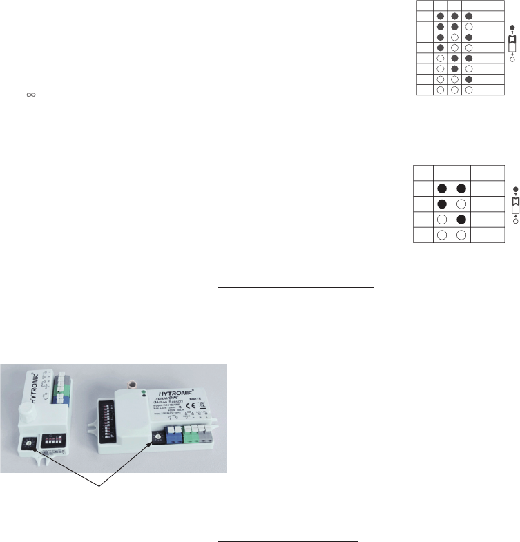
This determines the time the fitting remains at 100% level on motion detection and is set sith DIP swiches at the sensor
itself, refer to figure. The walk test seing is useful when installing the fitting to establish correct operation and range.
The following settings are available:
Hold time:
Daylight sensor:
This setting holds off the 100% light output should there sufficient daylight andis set using DIP switches at the sensor, refer
to figure. The following settings are available:
Detection Area:
This determines the effective range of the motion detector and is set by DIP switches at the sensor itself, refer to figure.
Note that reducing the sensitivity will also narrow the detection range.The following settings are available:
*In disable mode the lamp(s) will always be on with motion detected and operate at 100% light output, even in bright daylight.
I – 10%
II – 20%
III – 30%
IV – 50%
Settings for HC424RF
Stand-by period (corridor function)
This is the time period you would like to keep at the low light output level before it is completely switched off in the long absence of people.
I – 0S
II – 10S
III – 1 minute
IV – 5 minutes
V – 10 minutes
VI– 30 minutes
VII– 1 hour
VIII– +∞+∞
0S
10S
1min
5min
10min
30min
1h
I
II
III
IV
V
VI
VII
VIII
1 2 3
Stand-by dimming level
This is the dimmed low light output level you would like to have after the hold-time in the absence of people.
10%
20%
30%
50%
I
II
III
IV
1 2
RF grouping (max. 10 channels)
Using a screwdriver to adjust the rotary switch on both the master & slave unit, to keep them pointing at the same channel, the grouping is then
automatically completed. 10 channels (max. 10 groups) available for both the master & slave unit.
Using a screwdriver to point the arrow to the same position on the master unit and slave units.
master
slave
SECTION 4 RF GROUPING
SECTION 5 FUNCTIONS
5.1 100H burn-in mode for fluorescent lamp
With simple operation, rapidly turn off/on the fixture 3 cycles wihin 3 sec. (the green LED on the sensor flashes and the fixture
blinks 3 times to indicate the success of setup), lamp will be 100% on for 100 hours, and then automatically goes to sensor mode
after 100 hours. This is crucial to secure the lifetime of fluorescent lamp, when new fixture is installed,or old lamp is replaced.
This 100h burn-in feature can be cancelled by turn off/on the fixture 1 cycle within 1 sec.
With simple operation, rapidly turn off/on the fixture 2 cycles within 2 sec:
a. the green LED on the sensor flashes slowly for 5 seconds, meanwhile the fixture blinks twice.
b. the daylight sensor measures and remembers the surrounding lux for 1 sec.
c. the fixture and green LED is on for 10s to indicate the success of learning.
5.2 Ambient daylight threshold
This feature enables the fixture to function well in any real application circumstance, where the daylight penetrated
into fixture may vary a lot.
The latest surrounding lux value overwrites previous lux value learned.
Both the setting on DIP switch and the learned ambient lux threshold can overwrite each other.The latest action stays in validity.
*
*
*
Note: “0s” means on/off control; “+∞” means 2 steps of dimming control, fixture never switch off.

Designed in the software, the sensor switches on/off the load right on the zero-cross point, to ensure the min. current passing through
the relay contact point, and enable the max. load and life-time of the relay.
5.3 Zero-cross relay operation
Double L N terminal makes it easy for wire loop-in and loop-out, saves the cost of terminal block and assembly time.
5.4 Loop-in and loop-out
1-10v output on the master unit HC418V / RF is isolated, SELV output; while the 1-10v on the slave unit HC424RF is
non-isolated.
Motion sensor overwrites daylight sensor, meanning the daylight sensor starts to check the ambient natural light only when the
lamp is switch off (motion hold-time ellapsed).
*
*
SECTION 6 TROUBLE SHOOTING
YDEMER ESUAC YDEMER ESUAC NOITCNUFLAM
The load will not work
gnittes tsujdA detceles gnittes lortnoc-thgil tcerrocnI
daol ecalpeR ytluaf daoL
NO hctiwS FFO hctiws sniaM
gnittes enoz kcehC enoz noitceted eht ni tnemevom suounitnoC no syawla si daol ehT
The load is on without any identifiable
movement
The sensor is not mounted for reliably detecting movement Securely mount enclosure
Movement occurred, but not identified by the sensor
(movement behind wall, movement of small object in
immediate lamp vicinity etc.)
Check zone setting
The load will not work despite movement Rapid movements are being suppressed to minimize
malfunctioning or the detection radius is too small Check zone setting
FCC NOTE:
This device complies with Part 15 of the FCC Rules.
Operation is subject to the following two conditions: (1) this device may not cause harmful interference, and (2) this device must
accept any interference received, including interference that may cause undesired operation.
THE MANUFACTURER IS NOT RESPONSIBLE FOR ANY RADIO OR TV INTERFERENCE CAUSED BY UNAUTHORIZED
MODIFICATIONS OR CHANGE TO THIS EQUIPMENT. SUCH MODIFICATIONS OR CHANGE COULD VOID THE USER’S
AUTHORITY TO OPERATE THE EQUIPMENT.