Hyundai Digital Technology STB-100H Digital Cable Receiver User Manual HSC 1190NA manual
Hyundai Digital Technology Co., Ltd. Digital Cable Receiver HSC 1190NA manual
User Manual
E M C
STB-100H
USER'S MANUAL
DIGITAL CABLE RECEIVER
CONTENTS
1. Notice 2
2. Safety/Precautions 2
2.1. Safety
2.2. Precautions
3. Menu Map 3
4. Front Panel 4
5. Rear Panel 5
6. Operation 6
7. Specifications 7
Note: This equipment has been tested and found to comply with the limits for a Class B
digital device, pursuant to part 15 of the FCC Rules. These limits are designed to provide
reasonable protection against harmful interference in a residential installation. This
equipment generates, uses and can radiate radio frequency energy and, if not installed and
used in accordance with the instructions, may cause harmful interference to radio
communications. However, there is no guarantee that interference will not occur in a
particular installation. If this equipment does cause harmful interference to radio or
television reception, which can be determined by turning the equipment off and on, the user
is encouraged to try to correct the interference by one or more of the following measures:
◎ Reorient or relocate the receiving antenna.
◎ Increase the separation between the equipment and receiver.
◎ Connect the equipment into an outlet on a circuit different from that to which the receiver
is connected.
◎ Consult the dealer or an experienced radio/TV technician for help.
Modifications not expressly approved by the manufacturer could void the user's authority to
operated the equipment under FCC rules.
Safety/Precautions
1.1 Notice
* Theft of service is a crime.
* Installing this device without permission or unauthorized tampering,
modifying or altering it in any way may subject you
to civil or criminal penalties.
WARNING : To prevent electric shock, DO NOT REMOVE COVER.
No user serviceable parts inside.
2.1 Safty
* Be sure to read the user's manual before starting
the operation of the unit.
* Do not touch the power cord with wet hands as it may cause
electric shock.
* Never open the cover. It is very dangerous to touch
the inside of the unit due to possible electric shock.
* Place the unit in a well ventilated and no-heat environment.
* When you do not use this unit for a long time, make sure
that power cord is pulled out from the outlet. Also do not use
a damaged power cord as it may cause fire or electric shock.
* A professional installation is required. If reception is interrupted,
contact Melita Cable customer service.
2.2 Precautions
When installing the unit
* Install the unit horizontally. An uneven installation may cause
the unit to be damaged.
* Do not put heavy items such as a TV on the unit. That may cause the unit to be
damaged.
* Do not leave the unit where the water drops or splashs.
* Do not put water holding items such as vase on the unit.
Where it is subject to vibrations
Where it is exposed to direct sunlight
Where there is humidity
Where the temperature is too high or too low.
Where there is no ventilation
* Moving the unit to a hot area from a cold one will cause condensation.
* Do not operate the unit for one or two hours or until it has dried completely.

Menu Map
3. Menu Map
Main Menu channel List TV Channels
MUSIC Channels
Applications
Favorite List
Parental Control
Language
Timer
Configration Display Preferences
TV/VCR Setup
Decoder Info
Software upgrade
Diagnose
Factory Reset
Front panel
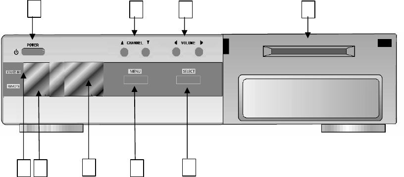
4. Front Panel
1. Standby/Power on Indication light : Turn on red light while in “standby mode” and turn off
red light while in “power on mode”.
2. Remote Control Indication light : Flashes green when receiving data from Remote Control Unit.
3. Power : To switch the receiver in "standby mode” or in “power on mode”.
4. Remote Sensor : Receives the infrared signal from Remote Control Unit.
5. To launch or terminate the menu application.
6. : To activate a highlighted item or go to next level on hypertext menu or confirm the user’ s
action.
7. channel : To change channel or cursor position on the application screen.
8. Volume : To adjust the volume level or change the value of an item
9. Smart Card Slot : Insert a smart card fully into the slot.
1 2
3
456
7 8 9
REAR PANEL VIEW
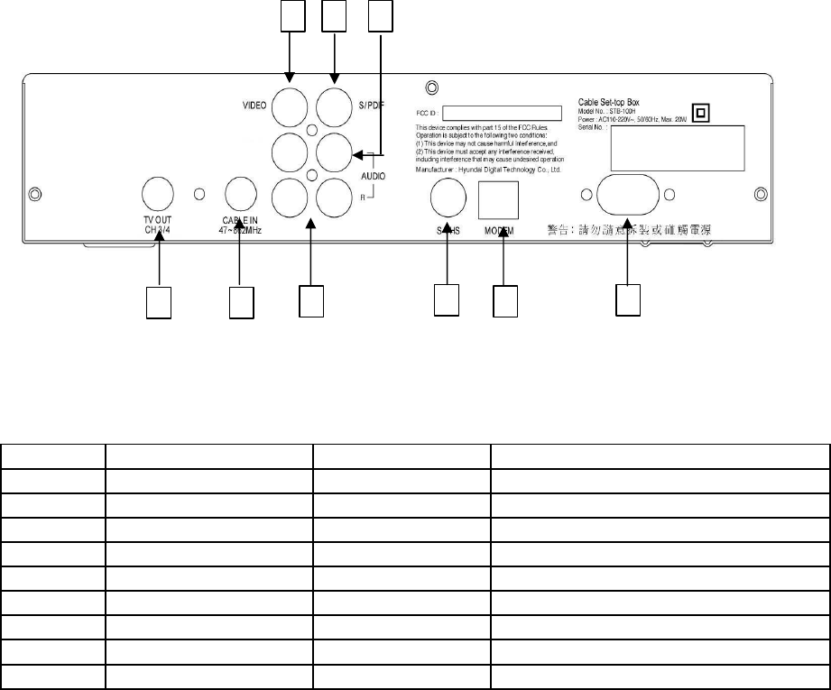
4. REAR PANEL VIEW
No Name Connector Function
1TV OUT(Ch 3/4)
IEC 169-24, female
RF re-modulation output.
2CABLE INPUT
IEC 169-24, female
Cable signal input to Digital tuner.
3CVBS RCA cinch Composite video output.
4S/PDIF RCA cinch Digital Audio output.
5AUDIO L RCA cinch X2 Left audio output.
6AUDIO R RCA cinch X2 Right audio output.
7S-VIDEO 4p Din s-video video output
8MODEM RJ-11 Connection to teline
9AC INPUT EN60320 AC power output
1 2
3 4 5
6789
REMOTE CONTROL UNIT
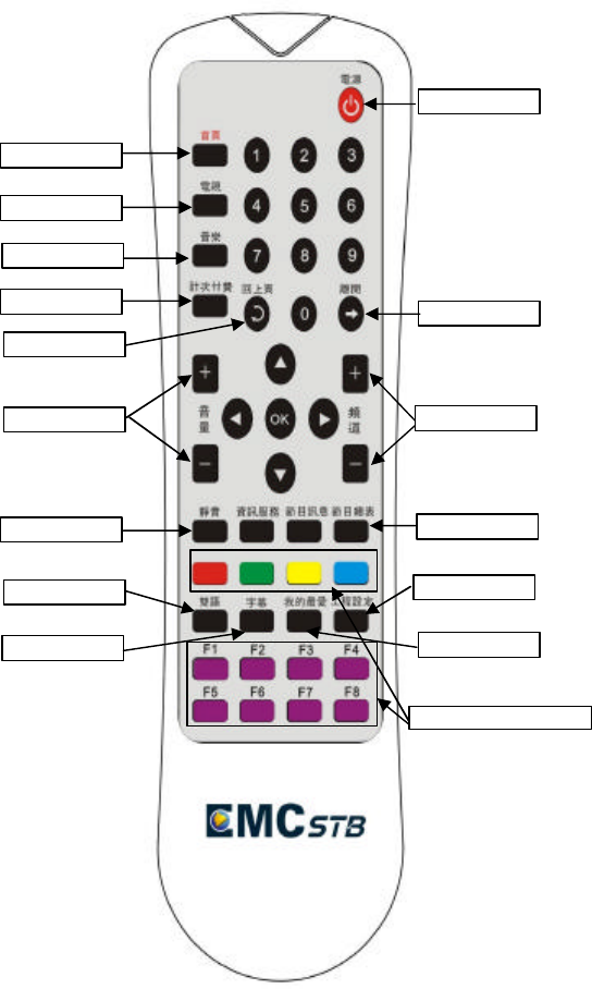
5. Remote Control Unit
1. POWER : To switch into ‘standby’ or
power on’ mode.
2. Homepage : Moving to selected
homepage
3. TV : Show the TV channel
4. Music : Show the music channel
5. PPV
6. Back:To return previous channel.
7. Exit:To return to previous status or menu
8. Volum:To adjust the volume level.
9. Channel:To change channel.
10. Mute:To turn the sound on/off.
11. Program :selection program
12. Laguege:To change the Laguege
13. Menu:To enter the main menu.
14. Subtitle:To see Subtitle.
15. Favorite:To see Favorite channel list.
16. Function&Hotkey
2. Home
3. TV
4. Music
5. PPV
8. Volum
10. Mute
12. Laguage
14. subtitle
6. Back
1. Power
7. Exit
9. Channel
11. Program
15. Favorite
13. Menu
16. Function&Hotkey
Operation
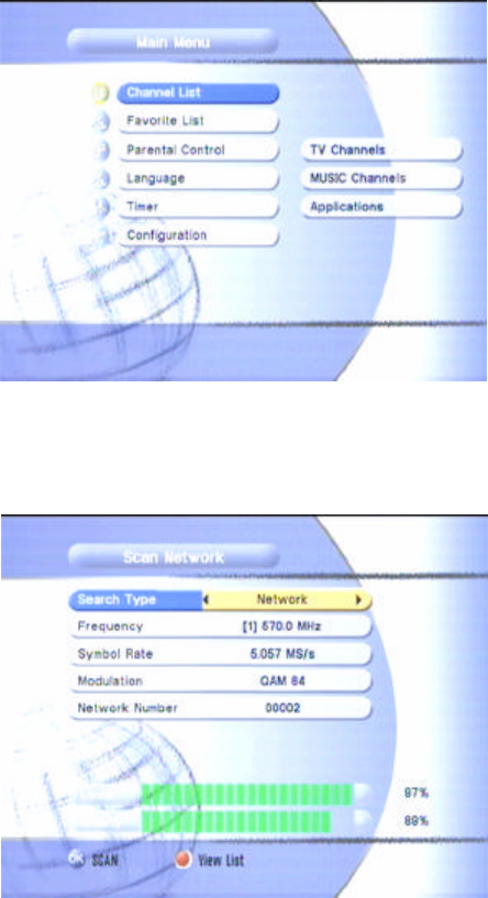
6. Channel scanning
- Press number key"007911" in above main menu
- After entering "scan network" menu, set up below values according to network set up.
* Frequency: Using number key in RCU
* Symbol rate: Using number key in RCU
* Modulation: Using right/left key in RCU
- After finishing network set up, press OK key in order to signal locking.
- After checking Level and Quality, press exit key.

Specifications
7. Specifications
System capabilities Fully DVB-C(QAM) system
Connector IEC 169-24, female
Input Frequency range 47~862Mhz
Signal level -15 ~ +15 dBmV
Tuner input & Input Impedance 75 ohm
Modulation Format 64, 128, 256 QAM
FEC Annex A & C
Front end CABLE
Symbol rate 4 ~ 5.2Msps
IF Band width 6 MHz
Processor 32bit processor
SDRAM 16Mbyte
FLASH 8Mbyte
EEPROM 32Kbyte
Video Decoder MPEG 2 Main Proflie @ Main Level
Data Rate up to 15M bits/s
Resolution 720 X 480
Video format NTSC
Aspect Ratio 4:3, 16:9
MPEG Audio MPEG 1 layer 1 & 2
Type Mono, Dual mono, Stereo, Joint Stereo
Sampling rates 32, 44.1 and 48 KHz
Remote control Code NEC-IR
Operating condition up to 7 Meter
Power supply Power consumption 20W
Supply voltage 90 ~ 250V
Supply frequency 50Hz ~ 60Hz
Rear panel CVBS Video output (1 cinch)
Connectors RCA Connector Audio L/R output(4 cinch)
Digital Audio output(1 cinch)
Digital tuner input IEC 169-24, female
RF out put IEC 169-24, female
Physical Size(W X H X D) 260 X 53.5 X 235 (mm)
Specification Weight(Net) 2.3Kg