Hyundai IBT G73TR Dual Function Touch Monitor User Manual
Hyundai IBT Corp. Dual Function Touch Monitor
User manual
NEXT
User’s Guide
Type No. L17T0D071
Model. G73TR
Dual Function Touch Monitor

U.S.A.
U.S.FEDERAL COMMUNICATIONS COMMISSION
RADIO FREQUENCY INTERFERENCE STATEMENT
INFORMATION TO THE USER
NOTE : This equipment has been tested and found to comply with the limits for a
Class B digital device pursuant to Part 15 of the FCC Rules.
These limits are designed to provide reasonable protection against harmful
interference in a residential installation.
This equipment generates, uses, and can radiate radio frequency energy and, if
not installed and used in accordance with the instructions, may cause harmful
interference to radio communications.
However, there is no guarantee that interference will not occur in a particular
installation.
If this equipment does cause harmful interference to radio or television reception,
which can be determined by turning the equipment off and on, the user is
encouraged to try to correct the interference by one or more of the following
measures:
Reorient or relocate the receiving antenna.
Increase the separation between the equipment and receiver.
Connect the equipment into an outlet of a circuit different from that to which
the receiver is connected.
Consult the dealer or an experienced radio/TV technician for assistance.
Changes or modification not expressly approved by the party responsible for
compliance could void the user's authority to operate the equipment.
Connecting of peripherals requires the use of grounded shielded signal cables.

WE HYUNDAI IT CORP.
Ami-ri Bubal-Eub Ichon-Si Kyungki-Do
467-860 KOREA
declare under our sole responsibility that the product:
to which this declaration relates is in conformity with the
following standard(s) or other normative document(s)
following the provisions of the Low Voltage Directive 73/23/EEC,
93/68/EEC and the EMC Directive 89/336/EEC.
KOREA / May 6, 2008
Jong Won, Choi
(Place and date of issue) (Name and signature of
authorized person)
DECLARATION OF CONFORMITY
Kind of equipment : Dual Function Touch Monitor
Type-Designation : L17T0D071
Safety : IEC60950-1:2002
EMC : EN 55022/2006(Class B)
EN 55024/A2 : 2003
EN61000-3-2:2006
EN61000-3-3/A2:2005
TUV SUD Product Service GmbH
Ridlerstrasse 65 - 80339 Munchen - Germany
Contents
1. Introduction ...........................................1/24
2. Safety Information .................................1/24
3. Installing the monitor ............................4/24
3-1. Packing List ..........................................4/24
3-2. Selecting a suitable location ...............5/24
3-3. Rear View & Signal Input Jacks .........6/24
3-4. Connecting the monitor .......................6/24
3-5. Setting the refresh rate ........................9/24
Preset Timing Table ...........................10/24
3-6. Way to Install driver for touch
monitor ................................................11/24
3-7. User’s Environment .............................12/24
4. Adjusting the picture .......................14/24
4-1. Using the On Screen Display ........15/24
4-2. Direct access buttons ....................15/24
4-3. OSD Adjustments ...........................16/24
5. Display power management ........... 20/24
Reducing power consumption ............20/24
6. Troubleshooting ...............................21/24
7. Specifications ...................................24/24
1. Introduction
2. Safety Information
1/24
This manual contains instructions for installing and operating
HYUNDAI IT G73TR.
HYUNDAI IT G73TR. is a highly ergonomic color display unit.
7YLHZDEOH6;*$/&'
+LJKTXDOLW\VFreen rHVFDOLQJFDSDELOLW\
9(6$'306'LVSOD\3RZHU0DQDJHPHQW6LJQDOLQJ
9(6$''&%FRPSDWLELOLW\
$GYDQFHGGLJLWDO2Q6Freen-Display controls
)DVWDQGDFFXUDWHDXWRDGMXVWPHQW
0RVWDGYDQFHGLPDJHVFDOLQJ
6XSSRUWLQJ9(6$)ODW3DQHO0RQLWRU3K\VLFDO0RXQWLQJ,QWHrface
'LJLWDO6LJQDO,QSXWE\'9,&RPSDWLELOLW\
ZULH5HVLVWLYHTRXFKPRQLWRU*7375
7KLV0RQLWRUKDVEHHQHQJLQHHred and manufactured to assure your safety.
You can prHYHQWVHULRXVHOHFWULFDOVKRFNDQGRWKHUKD]DrGVE\NHHSLQJLQPLQG
WKHIROORZLQJ
'RQRWSODFHDQ\WKLQJZHWRQWKHPRQLWRURUWKHSRZHU
corG1HYHUFRYHUWKHYHQWLODWLRQRSHQLQJVZLWKDQ\
PDWHULDODQGQHYHUWRXFKWKHPZLWKPHWDOOLFRU
LQIODPPDEOHPDWHULDOV
2/24
Avoid operating the monitor in extreme heat,
humidity or areas affected by dust.
Temperature : 5~35°C
Humidity : 30~80RH
Be sure to turn the monitor off before plugging the
power cord into the socket. Make sure that the power
cord and the other cords are securely and rightly
connected.
Overloaded AC outlets and extension cords are
dangerous, as are frayed power cords and broken
plugs, which may cause electric shock or fire. Call
your service technician for replacement.
Do not use sharp tools such as a pin or a pencil near
the monitor, as they may scratch the LCD surface.
Do not use a solvent, such as benzene, to clean the
monitor, as it will damage the LCD surface.

Cleaning and Maintenance
To avoid risk of electric shock, do not disassemble the display unit cabinet. The
unit is not user-serviceable. Remember to unplug the display unit from the
power outlet before cleaning.
'RQRWXVHDOFRKROPHWK\OHWK\ORULVRSropyl) or any strRQJGLVVROYHQW'RQRW
use thinner or benzene, abrasive cleaners or compressed air.
'RQRWZLSHWKHVFreen with a cloth or sponge that could scratch the surface.
To clean your antistatic screen, use water and a special microfiber screen
cleaning tissue used in optical lens cleaning, or lightly dampen a soft, clean
cloth with water or a mild detergent.
,IWKHLQVWUXFWLRQVDERYHGRQRWKHOSLQremoving stains, contact an authorized
service agent.
7KHPDLQSOXJIRUWKHSRZHUFRUGVKDOOEHUHDG\IRUEHLQJ used at any time.
$QDSSDUDWXVZLWK&ODVV,FRQVWUXFWLRQVKDOOEHFRQQHFWHG to a main socket
outlet with a protective earthing connection.
3/24
4/24
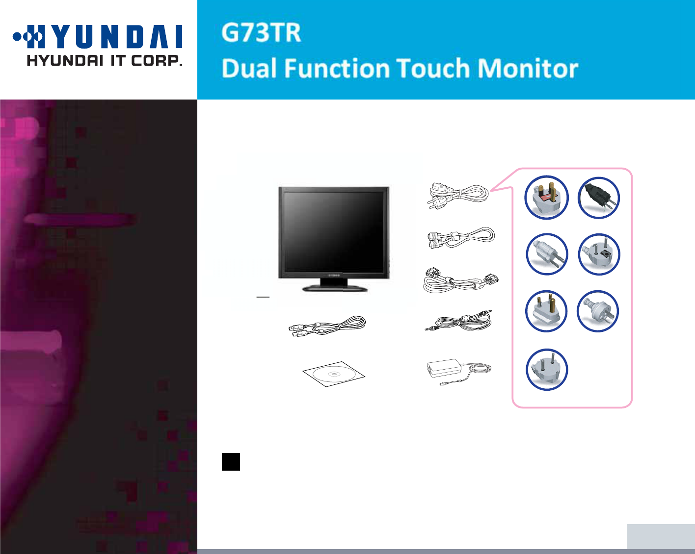
The following items should be found in the packaging.
Above power cord can be changed upon different voltage areas. Please
contact your dealer if anything is missing or damaged.
Other power cord except the cord packed in the product or longer than 3m
may affect EMC of the product in operating condition.
3. Installing the
monitor
3-1. Packing List
!
UK
America/Canada
Japan
Australia
Korea
Europe
South Africa
Power Cord
Signal Cable
Audio Cable
DVI-D Cable
USB Cable
Manual CD & Touch
Install CD
AC/DC Power
Adapter
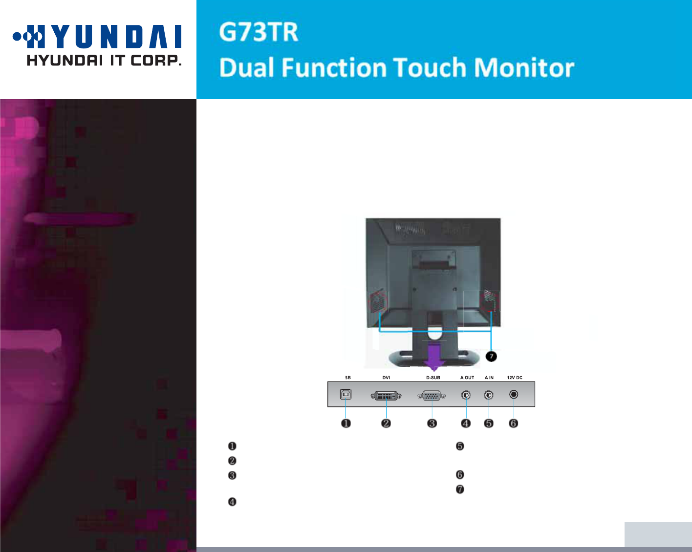
86%&RQQHFWWR86%RI3&
3RZHU,Q9'&&RQQHFWWR$&'&$GDSWRU
$XGLR,Q&RQQHFWWRWKHMDFN$XGLR2XWoI3&
2XWSXW3&6RXQG
$XGLR2XW&RQQHFWWR+HDG3KRQH
'6XE&RQQHFWWRWKHMDFN'6XE$QDORJ
RI3&
'9,&RQQHFWWRWKHMDFN'9,'LJLWDORI 3&
6SHDNHU2XWSXW3&VRXQG
USB '9, $,1 9'&$287'68%
5/24
3-2. Selecting a suitable
location
3-3 Rear View & Signal
input Jacks
3ODFHWKHPRQLWRUDWOHDVWFPIrRPRWKHUHOHFWULFDORUKHDWHPLWWLQJHTXLSPHQWDQGDOORZDW
OHDVWFPRQHDFKVLGHIRUYHQWLODWLRQ
3ODFHWKHPRQLWRULQDSRVLWLRQZKHrHQROLJKWVKLQHVGLrectly onto or is rHIOHFWHGRQWKHVFreen.
To rHGXFHH\HVWUDLQDYRLGLQVWDOOLQJWKHGLVSOD\XQLWDJDLQVWDEULJKWEDFNJrRXQGVXFKDVD
ZLQGRw.
3RVLWLRQWKHPRQLWRUVRWKDWWKHWRSRIWKHVFrHHQLVQRKLJKHUWKDQH\HOHYHO
ˍGGG
3RVLWLRQWKHPRQLWRUGLrHFWO\LQIrRQWRI\RXDWDFRPIRUWDEOHrHDGLQJGLVWDQFHDrRXQGWRFP
6/24
3-4. Connecting the
monitor
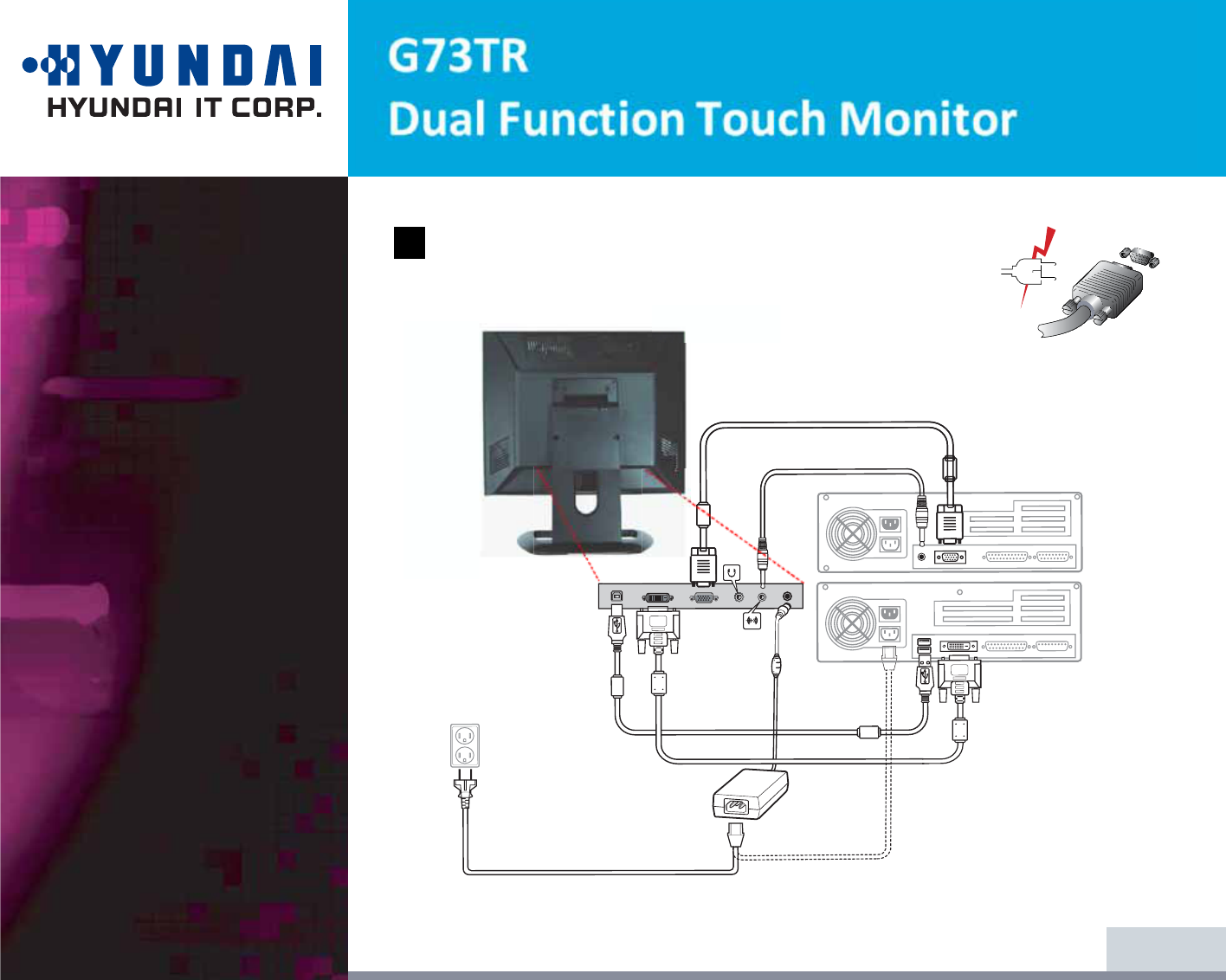
Before you start cabling your monitor, check that the
power is off on all units. To avoid any possibility of
electric shock, always connect your equipment to properly
earthed outlets.
!
5. Insert the other 15-pin signal cable connector into the 15-pin VGA connection
on your computer and screw it down.
6. Plug the power cord connection to connection on the monitor.
7. Plug the other end of the power cord to your computer's main supply or to a
100V-240V earthed electrical outlet.
8. Turn on the monitor using the power switch and check that the power LED is
on. If not, repeat steps 1,2,3,4,5,6 and 7 or refer to the Troubleshooting section
of this guide.
9. Turn on the power to the computer. The picture will appear within about 10
seconds. Adjust the picture to obtain optimum picture quality. See section
Adjusting the picture in this guide for more information.
7/24
1. Connect AC/DC Power Cable to Adaptor and then connect
Adaptor Cable to Monitor through the jack "12V DC" .
2. One end of "Audio Cable" to PC through the jack, "Audio Out".
And the other end to Monitor " Audio In".
3. Connect PC and Monitor through the jack, D-Sub (Analog signal) with D-Sub cable
4. Connect PC and Monitor through the jack , DVI (Digital signal) with DVI Cable.
$XGLRV\VWHP2SWLRQ
0RGHO
8/24
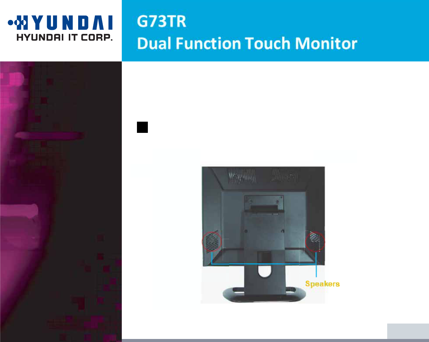
!!
7KLVPRQLWRUKDVDQDXGLRV\VWHPLQFOXGLQJWZRPLFURORXGVSHDNHUV(DFKRIWKH
WZRPLFURORXGVSHDNHUVKDVDQ1:PD[RXWSXWSRZHU7KLVV\VWHPDOVRVXSSRUWV
DKHDGSKRQHRXWSXWMDFN
:KHQWKLVPRQLWRULVWXUQHGRQDXGLRLVDOZD\VVHWXSDVRIIPRGH3OHDVHXVH
$8',2GLUHFWDFFHVVEXWWRQRQWKHIURQWFRYHURU2Q6FUHHQ'LVSOD\WRSXW
DXGLRRQ

9/24
3-5. Setting the refresh
rate
Follow the instructions below to set your refresh rate in Windows
98/ME/XP/2000/VISTA/7.
1. Go to the configuration window(Start-Settings-Configuration window).
2. Double click on the ‘Display’ icon.
3. Click on the ‘Settings’ tab.
4. Click on the ‘Advanced’ button.
5. Click on ‘Adapter’ and select 60Hz from the list.
6. Click on ‘Apply’ to accept the selected value.
10/24
Preset Timing Table
.
If the signal from the system doesn't equal to the preset timing mode, adjust
the mode with reference to the user’s guide of video card because the screen
may not be displayed.
Optimum resoultion 1280 x 1024 @ 60Hz
!
No.
1
2
3
4
5
6
7
8
9
10
11
12
13
14
Resolution
640 x 350
720 x 400
640 x 480
640 x 480
640 x 480
640 x 480
800 x 600
800 x 600
800 x 600
800 x 600
832 x 624
1024 x 768
1024 x 768
1024 x 768
H-Freq
31.4 KHz
31.4 KHz
31.4 KHz
35.0 KHz
37.8 KHz
37.5 KHz
35.1 KHz
37.8 KHz
48.0 KHz
46.8 KHz
49.7 KHz
48.3 KHz
56.4 KHz
60.0 KHz
V-Freq
70 Hz
70 Hz
59 Hz
66 Hz
72 Hz
75 Hz
56 Hz
60 Hz
72 Hz
75 Hz
74 Hz
60 Hz
70 Hz
75 Hz
Mode
IBM
IBM
IBM
MAC
VESA
VESA
VESA
VESA
VESA
VESA
MAC
VESA
VESA
VESA
15 1152 x 864 67.5 KHz 75 Hz VESA
16 1152 x 870 68.7 KHz 75 Hz MAC
17 1280 x 1024 64.0 KHz 60 Hz VESA
18 1280 x 1024 80.0 KHz 75 Hz VESA
3-6.
Way to Install driver
for touch monitor
The driver for touch screen software enables to have mutual communication to
touch screen-controller through and SUB
Supporting organization
This utility program enables test for the correction and draw test through the
touch screen.Including addition and removal.
Supporting many languages
It's automatically installed according to the selected languages.
English,Chinese,French,Spanish,German,Japanese,Italian and Dutch are
available.
The procedures for installing touch driver is as follows.
1. Insert TouchKit-CD into CD-ROM driver.
2. If inserting CD, according to the type of OS, the program is executived
automatically and manually.
3. Please note the enclosed touch driver for the detailed installation of program.
11/24
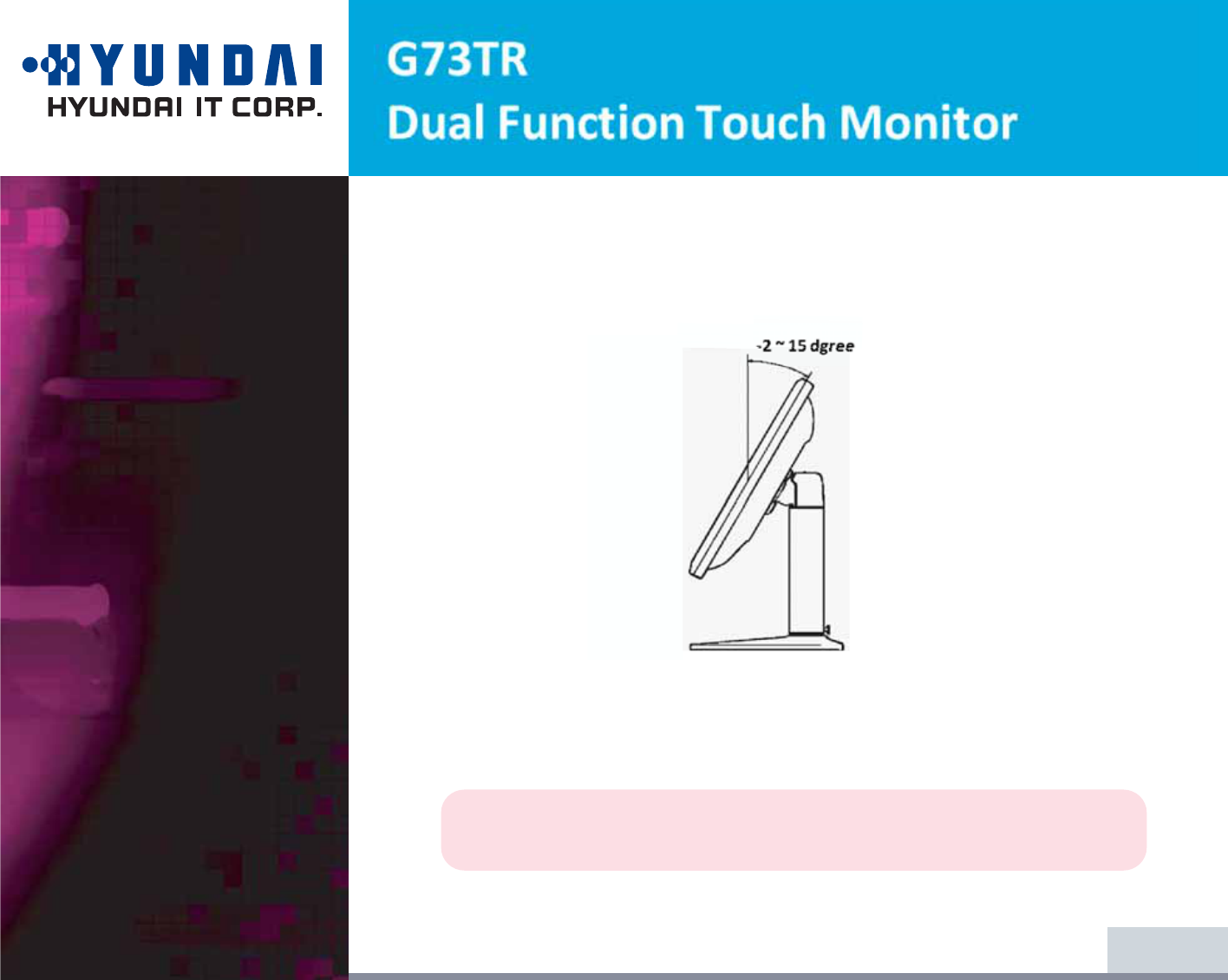
3-7. User’s Environment
Kensington Security
(Locking) Slot
Recommended Ergonomic User’s Environment
7LOWDQJOHRIWKHPRQLW RUVKRXOGEHEHWZHHQ-a15GHJUHH
7KLVGLVSOD\XQLWVXSSRUWVD.HQVLQJWRQW\SHVHFXULW\GHYice to secure your
monitor. Kensington lock is not included.
7RSXrFKDVHDQGLQVWDOOWKH.HQVLQJWRQORFNLQJGHYLFHSOHDVHrHIHUWRWKH
IROORZLQJFRQWDFWLQIRUPDWLRQ
* Kensington Technology Group
· Address : 2000 Alameda de las Pulgas 2F san mateo, California 94403-1289
· Tel : +1 650 572 2700 · Fax : +1 650 572 9675 · Web-site : www.kensington.com
12/24
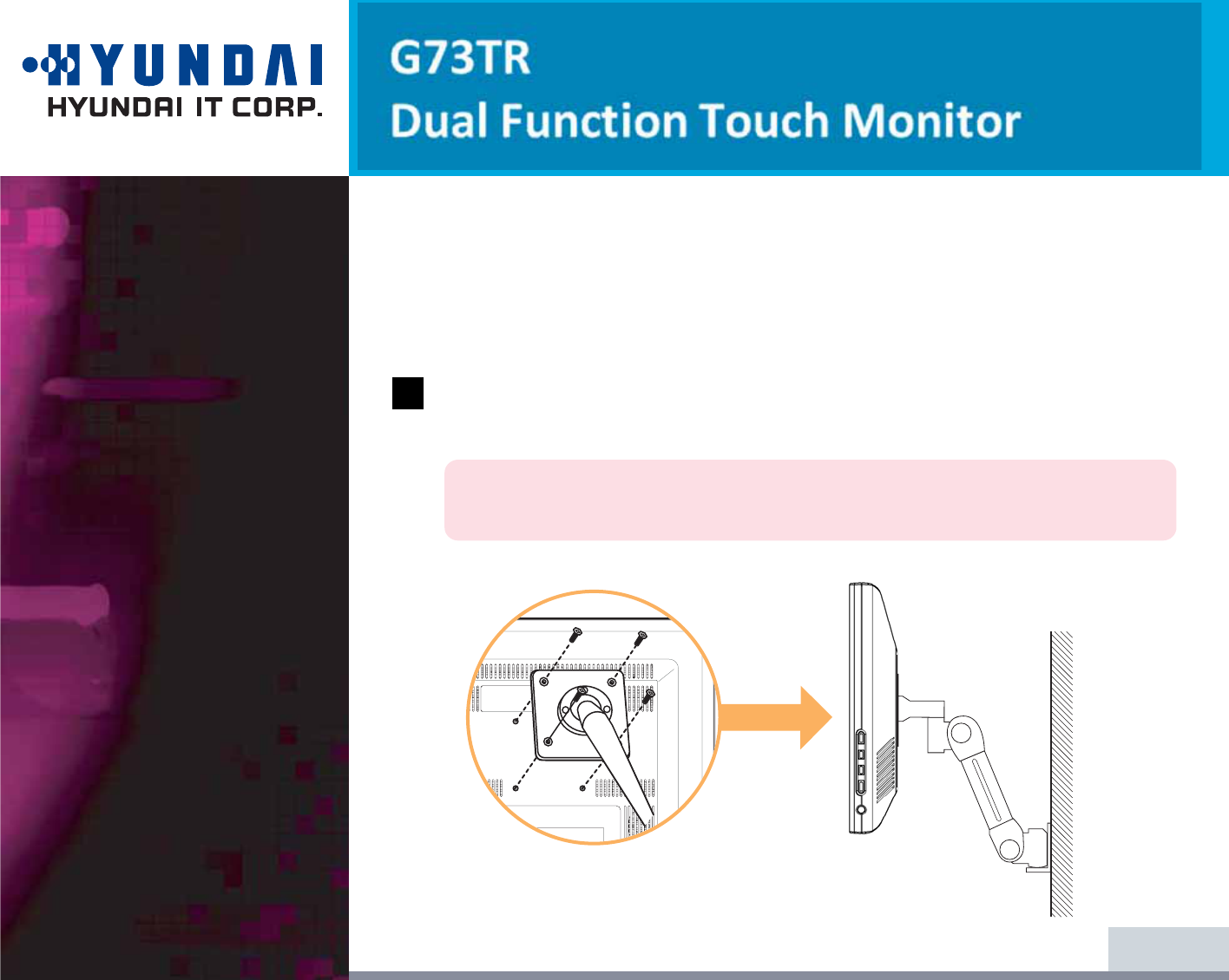
VESA MOUNT’G
7KLVGLVSOD\XQLWVXSSRUWV9(6$)3030,VWDQGDUGIRU75PP[75PPVFUHZ
PRXQWLQJE\JLYLQJVFUHZKROHVRQWKH5HDU&RYHURIWKHXQLW
)RUEX\LQJ9(6$)ODW3DQHO0RQLWRU0RXQWLQJ'HYLFHVSOHDVHFRQWDFW
IROORZLQJLQIRUPDWLRQ
2QO\0[VL]HVFUHZVKRXOGEHXVHGIRUSURSHUPRXQWLQJ
8VLQJZURQJVL]HVFUHZPD\FDXVHGDPDJHVWRWKHGHYLFH
* Ergotron, Inc.
· Address : Ergotron Europe Kuiperbergweg 50 1101 AG Amsterdam The Netherlands
· Tel : +3 1 20 696 60 65 · Fax : +3 1 20 609 04 59 · E-mail : info.eu@ergotron.com
13/24
!
4. Adjusting the picture
14/24
You can adjust the screen display by using the buttons located below the
screen.

4-1. Using the On Screen
Display
4-2. Direct access buttons
15/24
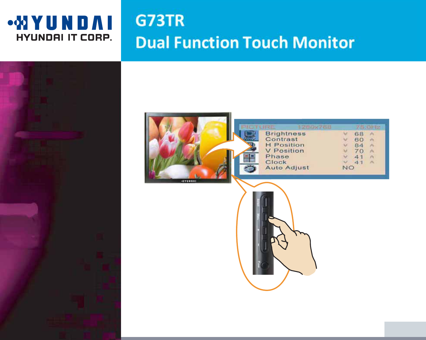
To make adjustments in the On Screen Display, follow these steps:
1. Push the MENU button to call the OSD to the screen.
2. Push the "+ " or "- " button to choose the item you want to adjust. The selected
item is highlighted.
3. Push the SELECT button to adjust the highlighted item.
4. Use the "+ " or "- " button to adjust the selection.
5. Push the MENU button to return to the previous menu if you are in a submenu.
6. The display unit automatically saves the new settings in 1 second after your
last adjustments and the menu disappears. You can also push the MENU button
to make the menu disappear.
LED LAMP
MENU
SELECT
POWER
DOWN / UP
(- / + )
LED Lamp shows the power on or off with its color.
When the power is on, LED Lamp is fluorescing with Green or
Amber color. In normal mode, its color is Green and in the save
mode, the color changes to Amber.
"MENU" button has the function to make OSD Window be on
the screen or disappear.
Decide the Input Signal between Analog and Digital.
Power ON or OFF
.
This button has 4 functions.
- Reducing/Increasing the sound volume.
- In OSD Menu, it makes cursor move down.
- In OSD Menu, it makes the data of Sub item decreased.
- In OSD Menu, it makes the data of Sub item move to the left.
4-3. OSD Adjustments
4-3. OSD Adjustments
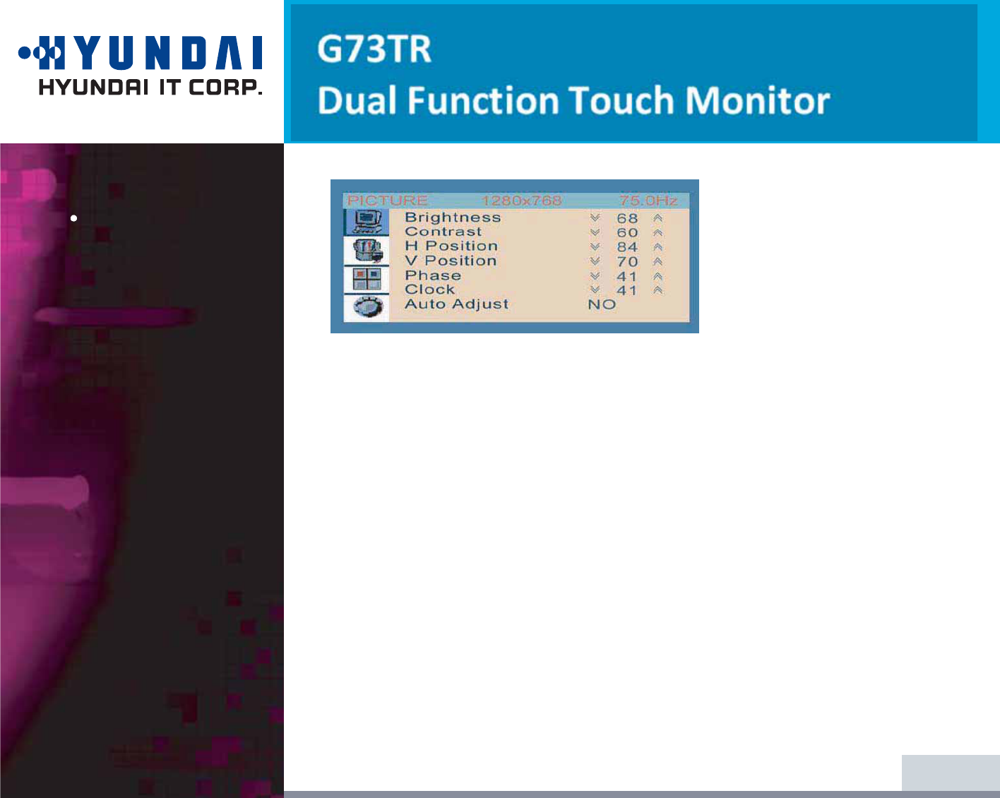
PICTURE
BRIGHTNESS
Adjusting the Brightness for all over the Screen.
(At factory, they have set the initial Brightness to 50.)
CONTRAST
Adjusting the Contrast for all over the Screen.
(At factory, they have set the initial Contrast to 50.)
H.POSITION
Moving the position of the screen horizontally.
V.POSITION
Moving the position of the screen vertically.
PHASE
Refine the Picture delicately.
CLOCK
Adjust the size of the Picture Horizontally.
* At DVI mode, H.POSITION,V-POSITION,PHASE,CLOCK,AUTO ADJUST
are not workable
16/24
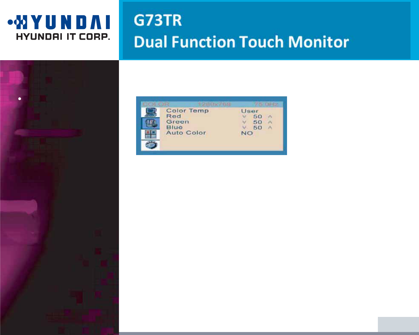
Color
AUTO ADJUST
Adjusting the Picture Status to the optimum automatically.
COLOR TEMPERATURE
Adjusting Color Tone for all over the Picture.( At Digital mode, it is it not workable
- USER : The user can adjust each color tone to its favorable tone like to the
Reddish, Greenish or Bluish.
When the adjustment is concluded, you can set it and exit from the
adjustment by pressing "MENU" button.
- Bluish : This makes the color tone of the picture to the Bluish.
- Reddish: This makes the color tone of the picture to the Reddish.
AUTO COLOR
The color for all over the screen is adjusted to the most desirable status
automatically.
* At DVI mode, AUTO ADJUST, COLOR TEMPERATURE, AUTO COLOR are not
workable
17/24

OSD
18/24
OSD H.POSITION
Move OSD Window horizontally.
OSD V.POSITION
Move OSD Window vertically
OSD TIMER
Select the time while OSD Window remains on the screen.
(10 Sec, 20 Sec, 30 Sec, 40 Sec)
TRANSPARENCY
Adjust the Transparency of OSD Window.

Miscellaneous
Hot Key
LANGUAGE
Decide the language for OSD Menu.
RECALL
If you select "Recall", the Picture will be out of the range and then
come back to the range at almost same time.
And all adjusted data will be back to the factory set.
INPUT SELECT
Decide the Input Signal between ANALOG and DIGITAL .
AUDIO
The sound from Speakers or Head Phone will be ON or OFF.
VOLUME
Adjusting the sound volume from speakers.
SOUND VOLUME
Press “ - ” button and Volume Control Bar appears on the screen.
And then by using “ - “(Reducing),“ + “ (Increasing) buttons,
you can adjust the sound volume.
MUTE
Press " UP " button, and two choices (Mute ON or OFF) appear on the right-bottom area of the
screen.
If you choose Mute ON, there will be No Sound. On the contrary, if Mute OFF, Sound will revive.
19/24
If the power management function of your computer is enabled, your monitor
turns on and off automatically. You can control power management features from
your computer.
Your computer may have power management features which enable the computer
or monitor to enter a power saving mode when the system is idle. You can
reactivate the system by pressing any key or moving the mouse.
The power button does not disconnect the monitor from the power source.
The only way to isolate the monitor completely from if to unplug the power
cable.
20/24
5. Display power
management
Reducing power
consumption
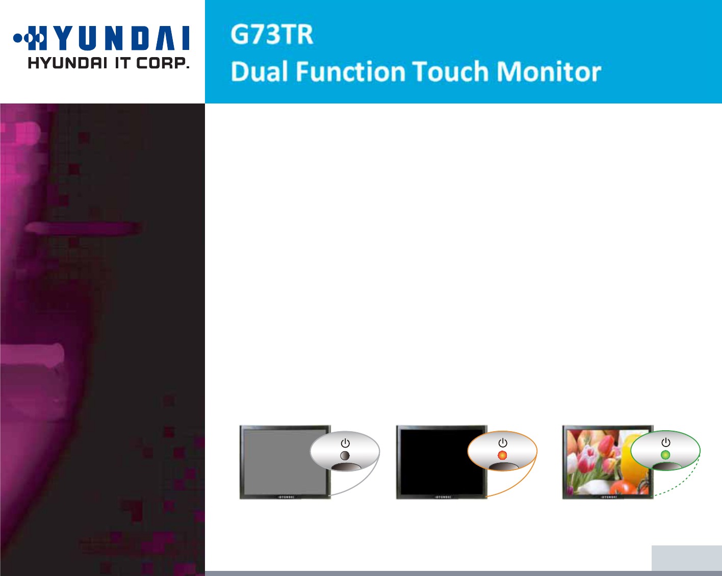
Power consumption
25 W(Max)
1 W(Typ)
0 W
Mode
Normal
off
Unplugged
LED
Green
Orange
Not illuminated
!

6. Troubleshooting
21/24
Problem
Blank screen
Error message:
Video mode not
supported
The display does
not enter power
management
mode
Possible solution
If the power LED is not lit, push the Soft power switch or check the
AC cord to turn the monitor on. If the display unit is powered
through the computer, check that the computer is switched on.
The display unit might be in standby mode. Push one of the
keyboard keys. Check that the keyboard is properly connected to
the computer.
Check that the signal cable connector is properly connected and that
the connection pins are not bent or damaged. If the connector is
loose, tighten the connector's screws.
Check that the power cable is correctly connected to the display unit
and to the power outlet.
Check the resolution and the frequency on the video port of your
computer.
Compare these values with the data in the Preset Timing Table.
The video signal from the computer does not comply with VESA
DPMS standard. Either the computer or the graphics adapter is not
using the VESA DPMS power management function.
If your monitor is not functioning properly, you may be able to solve the problem
by following suggestions below :
22/24
Possible solution
Check that the signal cable connector is properly connected and that
the connection pins are not bent or damaged. Try another color
temperature.
Adjust the picture characteristics as described in the section OSD
Adjustment (4-3).
A problem with your graphics adapter or display unit. Contact your
service representative.
Check that the display resolution and frequency from your PC or
graphic adapter is an available mode for your monitor.
In your PC, you can check through Control panel, Display, Settings.
If the setting is not correct, use your computer utility program to
change the display settings.
Check that the signal cable connector is properly connected and that
the connection pins are not bent or damaged.
If the connector is loose, tighten the connector’s screws.
Check that the computer is switched on.
To enter a power saving mode. You can reactivate the system by
pressing any key or moving the mouse.
Problem
Color defects
Size, position,
shape or quality
unsatisfactory
Duplicated
images
Image is not
stable
Message :
No signal
The power LED is
a orange color
Possible solution
LED Indicator can be appear orange on changing of video mode or
Input Signal.
Check the Resolution and the frequency on the video part of your
computer. Compare these values with the data in the Preset Timing
Table.
Problem
The power LED is
a orange color
23/24
Contacting service
If the above troubleshooting hints do not help you find a solution to the problem,
contact an authorized service agent. If the monitor is sent for service, use the
original package if possible.
Unplug the display unit from the power outlet and contact a service agent when:
7KHPRQLWRUGRHVQRWRSHUDWHQRUPDOO\DFFRrding to the operating instructions.
7KHPRQLWRUH[KLELWVDGLVWLQFWFKDQJHLQSHUIRUPDQFH
7KHPRQLWRUKDVEHHQGropped or the cabinet has been damaged.
7KHPRQLWRUKDVEHHQH[SRVHGWRUDLQRUDQ\NLQGRIOLTXid(like water) has
been spilled onto the monitor.
24/24
LCD
Display area
Number of color
Input signals
Frequency rate
Maximum bandwidth
Maximum resolution
Recommended resolution
Input voltage
Power consumption
Power management
Plug & Play
OSD menu
Audio system
VESA FPMPMI
Safety and EMC
Operating Temperature
Weight
Dimensions (W X H X D mm)
6SHFLILFDWLRQLVVXEMHFWWRFKDQJHZLWKRXWQRWLFH
+<81'$,,7&253VSHFLILFDWLRQRQ³GHDGSL[Hl´RI/&'3DQHODSSOLHVWR,626WDQGDUG
7. Specifications
17"viewable, Diagonal, Pixel pitch 0.264mm, A-Si TFT
337.92(H) x 270.336(V) mm
16.7 million colors
R.G.B Analog, 15 pin D-sub / Digital TMDS(DVI-D)
Horizontal : 31.0 to 80.0KHz, Vertical : 56 to 76Hz
135 MHz
Analog : 1280 x 1024@75Hz, Digital TMDS : 1280 x 1024@75Hz
1280 x 1024@60Hz
DC 12V 4A
25W(Max.)
VESA DPMS
VESA DDC 1/2B
BRIGHTNESS, CONTRAST, COLOR CONTROL, H/V-POSITION,
CLOCK PHASE, AUTO COLOR, LANGUAGE, AUTO ADJUST, AUDIO,
OSD H/V-POISTION, OSD TIMER, RECALL, INPUT SELECT
2ch x 1 watt / Ear Phone Jack
75 mm x 75 mm screw mounting
FCC Class B, NRTL, TUV, CB, CE, Energy Star
5 ~ 35
O
C
5.15Kg unpacked, 6.8Kg packed
440 X 450 X 160 mm