id Systems VAC4 Vehicle Asset Communicator VAC4 Series User Manual Installation Guide
I.D. Systems Inc. Vehicle Asset Communicator VAC4 Series Installation Guide
UserManual.wiki
>
id Systems
>
VAC4 User Manual
Installation Guide
Navigation menu
Upload a User Manual
Namespaces
Wiki Guide
HTML
PDF
Info
Views
User Manual
Discussion / Help
Navigation
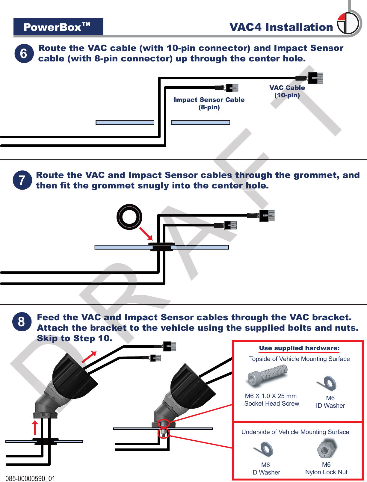
![3/8")(2 085-00000590_0135(17/64")Remove the bracket. Using a 6.75 mm(17/64") bit, drill holes at the two marked locations.Using the bracket base as a template, mark the mounting holelocations on the vehicle mounting surface, as shown below. Verify that the marked locations are 60 mm (2 3/8") apart.The VAC mounting bracket can be configured in multiple ways to accomodate the desired mounting location. If needed, change the VAC mounting bracket orientation by following the instruction sheet supplied with the bracket.4(1”)(optional center hole)If the VAC to vehicle and Impact Sensor cables will be routed through the vehicle’s mounting surface, drill a 25 mm (1”) hole at the exact center point between the two holes marked in Step 4 [30 mm (1 3/16”) from either hole]. If the cables will be routed along the vehicle’s mounting surface, do not drill a center hole and skip to Step 9. 60 mm6.75 mm25 mmVehic VAC4 InstallationPowerBoxTMD If the VAC to vehicle and Impact Sensor cables If the VAC to vehicle and Impact Sensor cables will be routed through the vehicle’s mounting will be routed through the vehicle’s mounting surface, drill a 25 mm (1”)surface, drill a 25 mm (1”)center point between the two holes marked in center point between the two holes marked in Step 4 [30 mm (1 3/16”) from either hole]. Step 4 [30 mm (1 3/16”) from either hole]. R Remove the bracket. Using a 6.75 mmRemove the bracket. Using a 6.75 mm(17/64") bit, drill holes at the two (17/64") bit, drill holes at the two marked locations.marked locations.R A AA A 3/8")A A AA Remove the bracket. Using a 6.75 mmRemove the bracket. Using a 6.75 mmAA 60 mm60 mmF F F F F F that the marked locations are 60 mm (2 3/8") apart.TUsing the bracket base as a template, mark the mounting holeUsing the bracket base as a template, mark the mounting holelocations on the vehicle mounting surface, as shown below. Verify locations on the vehicle mounting surface, as shown below. Verify VAC mounting bracket orientation by following the instruction sheet VAC mounting bracket orientation by following the instruction sheet T](https://usermanual.wiki/id-Systems/VAC4/User-Guide-2090686-Page-5.png)