id Systems VAC4 Vehicle Asset Communicator VAC4 Series User Manual Installation Guide
I.D. Systems Inc. Vehicle Asset Communicator VAC4 Series Installation Guide
Installation Guide

PowerBox
Installation Guide
085-00000590_0draft
Vehicle Asset Communicator (VAC4)
TM
This device complies with Part 15 of the FCC Rules and Industry Canada License-Exempt RSS Stadard(s).
Operation is subject to the following two conditions:
(1) This device may not cause harmful interface, and
(2) This device must accept any interferences received, including interference that may cause undesired operation.
L ‘ utilisation de ce dispositif est autorisée seulement aux conditions suivantes :
(1) il ne doit pas produire de brouillage et
(2) l’ utilisateur du dispositif doit étre prêt à accepter tout brouillage radioélectrique reçu, même si ce brouillage est susceptible de compromettre le fonctionnement du dispositif.
The transmitter must not be co-located or operated in conjunction with any other antenna or transmitter. This equipment complies with the FCC RF/IC radiation exposure limits set forth for an
uncontrolled environment. This equipment should be installed and operated with a minimum distance of 20 centimeters between the radiator and any part of your body.
Note: This equipment has been tested and found to comply with the limits for digital device, pursuant to Part 15 of FCC Rules.
These limits are designed to provide reasonable protection against harmful interference when the equipment is operated in a commercial environment. This equipment generates, uses, and can
radiate radio frequency energy and, if not installed and used in accordance with FCC instructions, may cause harmful interference to radio communications. However, there is no guarantee that
interference will not occur in a particular installation. If this equipment does cause harmful interference to radio or television reception, which can be determined by turning the equipment off and on,
the user is encouraged to try correcting the interference by one or more of the following measures:
1.1. Reorient or relocate the receiving antenna,
1.2. Increase the separation between the equipment and receiver.
1.3. Connect the equipment into an outlet on a circuit different from that to which receiver is connected.
1.4. Consult the dealer or experienced radio/TV technician for help.
WARNING
Changes or modifications not expressly approved by the manufacturer could void the user’s authority to operate the equipment.
This device complies with Part 15 of the FCC Rules and Industry Canada License-Exempt RSS Stadard(s).
This device complies with Part 15 of the FCC Rules and Industry Canada License-Exempt RSS Stadard(s).
Operation is subject to the following two conditions:
Operation is subject to the following two conditions:
(1) This device may not cause harmful interface, and
(1) This device may not cause harmful interface, and
(2) This device must accept any interferences received, including interference that may cause undesired operation.
(2) This device must accept any interferences received, including interference that may cause undesired operation.
L ‘ utilisation de ce dispositif est autorisée seulement aux conditions suivantes :
L ‘ utilisation de ce dispositif est autorisée seulement aux conditions suivantes :
(1) il ne doit pas produire de brouillage et
(1) il ne doit pas produire de brouillage et
(2) l’ utilisateur du dispositif doit étre prêt à accepter tout brouillage radioélectrique reçu, même si ce brouillage est susceptible de compromettre le fonctionnement du dispositif.
(2) l’ utilisateur du dispositif doit étre prêt à accepter tout brouillage radioélectrique reçu, même si ce brouillage est susceptible de compromettre le fonctionnement du dispositif.
The transmitter must not be co-located or operated in conjunction with any other antenna or transmitter. This equipment complies with the FCC RF/IC radiation exposure limits set forth for an
The transmitter must not be co-located or operated in conjunction with any other antenna or transmitter. This equipment complies with the FCC RF/IC radiation exposure limits set forth for an
uncontrolled environment. This equipment should be installed and operated with a minimum distance of 20 centimeters between the radiator and any part of your body.
uncontrolled environment. This equipment should be installed and operated with a minimum distance of 20 centimeters between the radiator and any part of your body.
Note: This equipment has been tested and found to comply with the limits for digital device, pursuant to Part 15 of FCC Rules.
Note: This equipment has been tested and found to comply with the limits for digital device, pursuant to Part 15 of FCC Rules.
These limits are designed to provide reasonable protection against harmful interference when the equipment is operated in a commercial environment.
R
R
R
A
A
A
A
A
A
A
A
F
PowerBoxPowerBox
Installation Guide
Installation Guide
TMTM
PowerBoxPowerBox
T
085-00000590_01
VAC4 Bill of Materials
Descrip on Qty
Vehicle Asset Communicator (VAC) 1
VAC Moun ng Bracket
1
Impact sensor kit
1
Hardware installa on kit 1
Electrical component kit 1
1
Recommended Tools
Needle nose pliers
Flashlight
Channel lock pliers
Electrical tape
Allen Wrench set
Metric socket set
Vehic VAC4 Installation
PowerBoxTM
D
R
R
R
R
R
R
R
R
R
R
R
R
R
R
R
R
R
R
R
Channel lock pliers
Channel lock pliers
R
R
R
R
R
R
R
R
R
R
A
Recommended Tools
Recommended Tools
A
A
A
A
A
A
A
A
A
A
A
A
A
Metric socket set
Metric socket set
A
A
A
A
A
A
A
A
A
A
A
A
A
A
A
A
A
F
F
F
F
F
F
F
F
F
F
F
F
F
F
F
F
F
F
F
F
F
F
F
1
F
F
F
F
F
F
F
F
F
1
F
1
F
F
F
T
Q
T
t
Q
t
Q
t
T
y
T
T
T
T
T
T
T
T
T
T
T
T
T
T
T
T
T
1
T
T
T
T
T
T
T
T
T
T
T
T
T

085-00000590_01
1System coordinator should first refer to the PowerBox VAC4 Getting
Started Guide for complete product overview.
©2013 I.D. Systems, Inc. All rights reserved. This document contains proprietary and confidential information
and may not be divulged to any third party without the express written consent of I.D. Systems, Inc.
201.996.9000
www.id-systems.com
For System Coordinator Responsible for
PowerBox™ System Implementation
201.996.9000 support@id-systems.com
Vehic VAC4 Installation
PowerBoxTM
PowerBox™
D
D
D
R
For System Coordinator Responsible for
R
R
R
A
A
A
A
F
F
F
F
T
T
T
T
201.996.9000
T
085-00000590_01
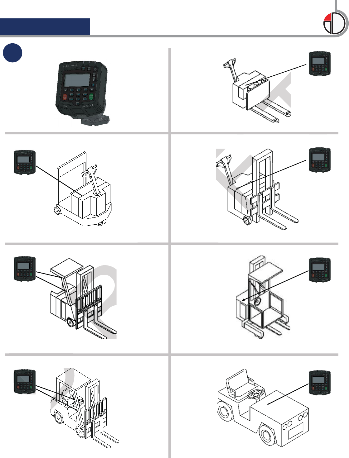
2Choose the VAC location.
Vehic VAC4 Installation
PowerBoxTM
D
D
D
D
R
A
A
F
F
F
F
T
T
T
3/8")
(2
085-00000590_01
3
5
(17/64")
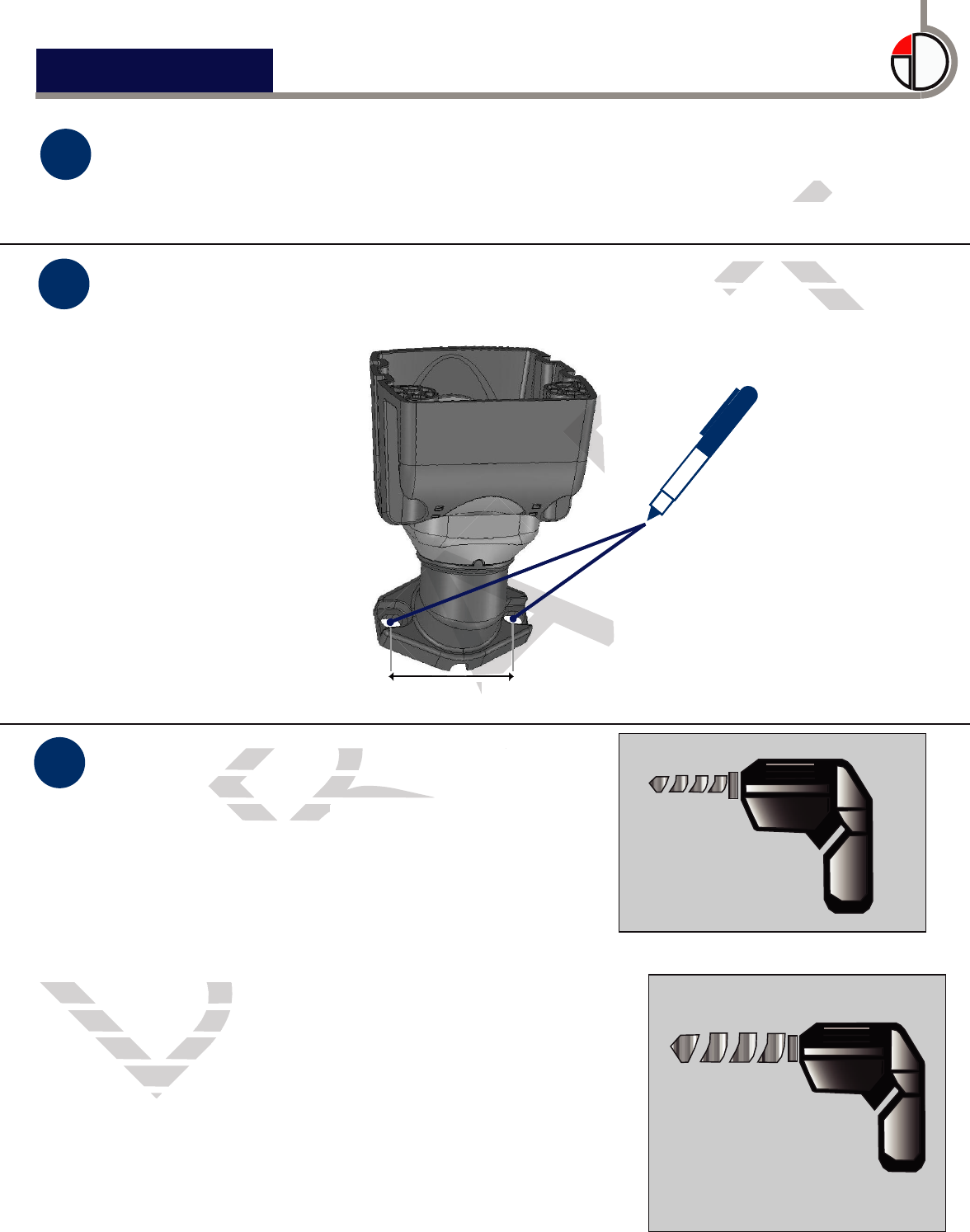
Remove the bracket. Using a 6.75 mm
(17/64") bit, drill holes at the two
marked locations.
Using the bracket base as a template, mark the mounting hole
locations on the vehicle mounting surface, as shown below. Verify
that the marked locations are 60 mm (2 3/8") apart.
The VAC mounting bracket can be configured in multiple ways to
accomodate the desired mounting location. If needed, change the
VAC mounting bracket orientation by following the instruction sheet
supplied with the bracket.
4
(1”)
(optional center hole)
If the VAC to vehicle and Impact Sensor cables
will be routed through the vehicle’s mounting
surface, drill a 25 mm (1”) hole at the exact
center point between the two holes marked in
Step 4 [30 mm (1 3/16”) from either hole].
If the cables will be routed along the vehicle’s
mounting surface, do not drill a center hole and
skip to Step 9.
60 mm
6.75 mm
25 mm
Vehic VAC4 Installation
PowerBoxTM
D
If the VAC to vehicle and Impact Sensor cables
If the VAC to vehicle and Impact Sensor cables
will be routed through the vehicle’s mounting
will be routed through the vehicle’s mounting
surface, drill a 25 mm (1”)
surface, drill a 25 mm (1”)
center point between the two holes marked in
center point between the two holes marked in
Step 4 [30 mm (1 3/16”) from either hole].
Step 4 [30 mm (1 3/16”) from either hole].
R
Remove the bracket. Using a 6.75 mm
Remove the bracket. Using a 6.75 mm
(17/64") bit, drill holes at the two
(17/64") bit, drill holes at the two
marked locations.marked locations.
R
A
A
A
A
3/8
")
A
A
A
A
Remove the bracket. Using a 6.75 mm
Remove the bracket. Using a 6.75 mm
A
A
60 mm
60 mm
F
F
F
F
F
F
that the marked locations are 60 mm (2 3/8") apart.
T
Using the bracket base as a template, mark the mounting hole
Using the bracket base as a template, mark the mounting hole
locations on the vehicle mounting surface, as shown below. Verify
locations on the vehicle mounting surface, as shown below. Verify
VAC mounting bracket orientation by following the instruction sheet
VAC mounting bracket orientation by following the instruction sheet
T
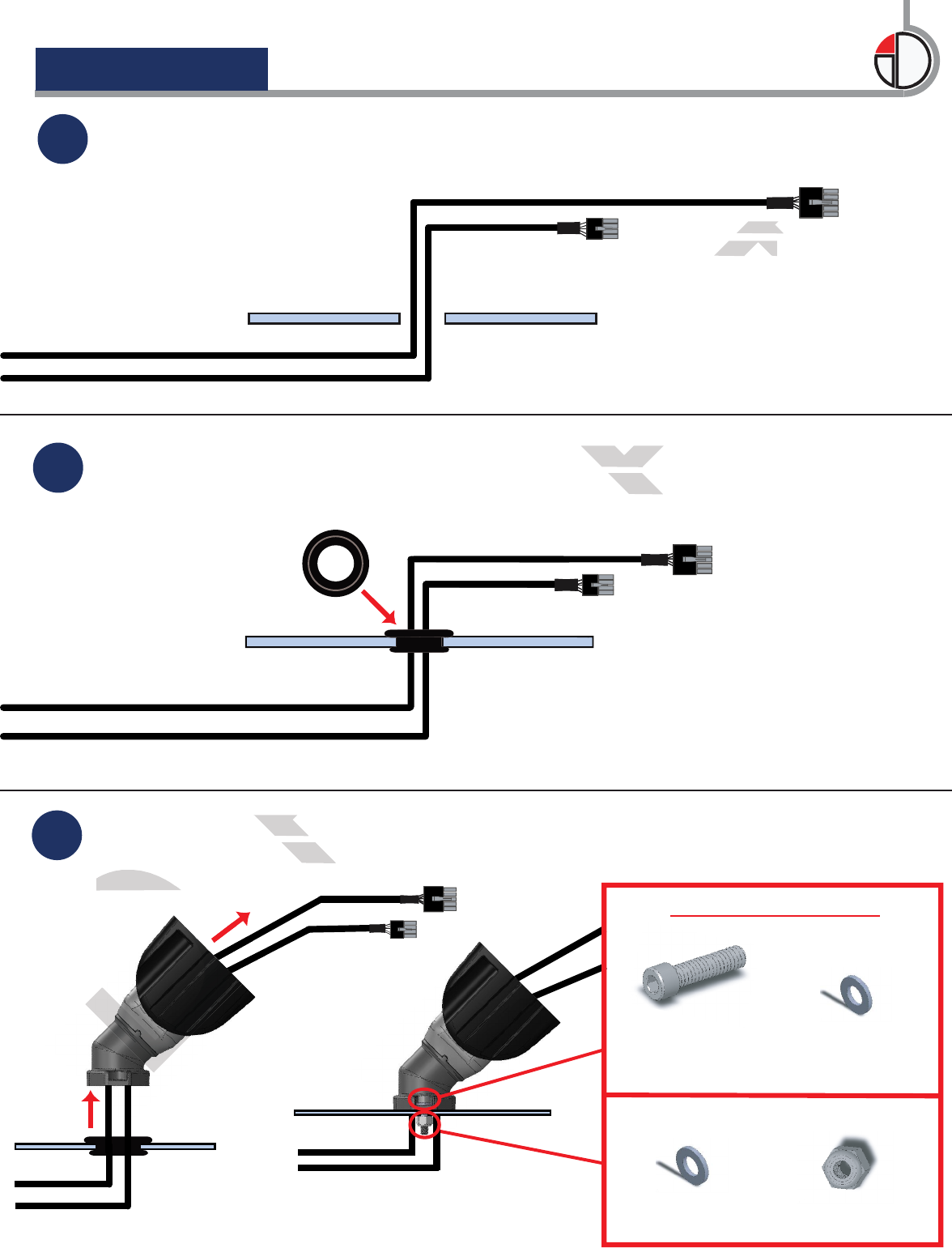
7Route the VAC and Impact Sensor cables through the grommet, and
then fit the grommet snugly into the center hole.
085-00000590_01
6Route the VAC cable (with 10-pin connector) and Impact Sensor
cable (with 8-pin connector) up through the center hole.
Feed the VAC and Impact Sensor cables through the VAC bracket.
Attach the bracket to the vehicle using the supplied bolts and nuts.
Skip to Step 10.
8
M6 X 1.0 X 25 mm
Socket Head Screw
M6
Nylon Lock Nut
Use supplied hardware:
Topside of Vehicle Mounting Surface
Underside of Vehicle Mounting Surface
M6
ID Washer
M6
ID Washer
Vehic VAC4 InstallationPowerBoxTM
VAC Cable
(10-pin)
Impact Sensor Cable
(8-pin)
D
D
D
Feed the VAC and Impact Sensor cables through the VAC bracket.
Attach the bracket to the vehicle using the supplied bolts and nuts.
Skip to Step 10.
Skip to Step 10.
D
R
Feed the VAC and Impact Sensor cables through the VAC bracket.
Feed the VAC and Impact Sensor cables through the VAC bracket.
Attach the bracket to the vehicle using the supplied bolts and nuts.
Attach the bracket to the vehicle using the supplied bolts and nuts.
R
R
R
A
A
A
then fit the grommet snugly into the center hole.
A
A
A
A
A
A
A
A
A
A
A
A
A
A
A
A
A
A
A
A
A
A
A
A
A
A
F
Route the VAC and Impact Sensor cables through the grommet, and
Route the VAC and Impact Sensor cables through the grommet, and
then fit the grommet snugly into the center hole.
then fit the grommet snugly into the center hole.
F
F
T
T
T
T
VAC Cable
VAC Cable
(10-pin)
(10-pin)
T
T
T
T
T
T
T
T
T
T
T
T
T
T
T
T
085-00000590_01
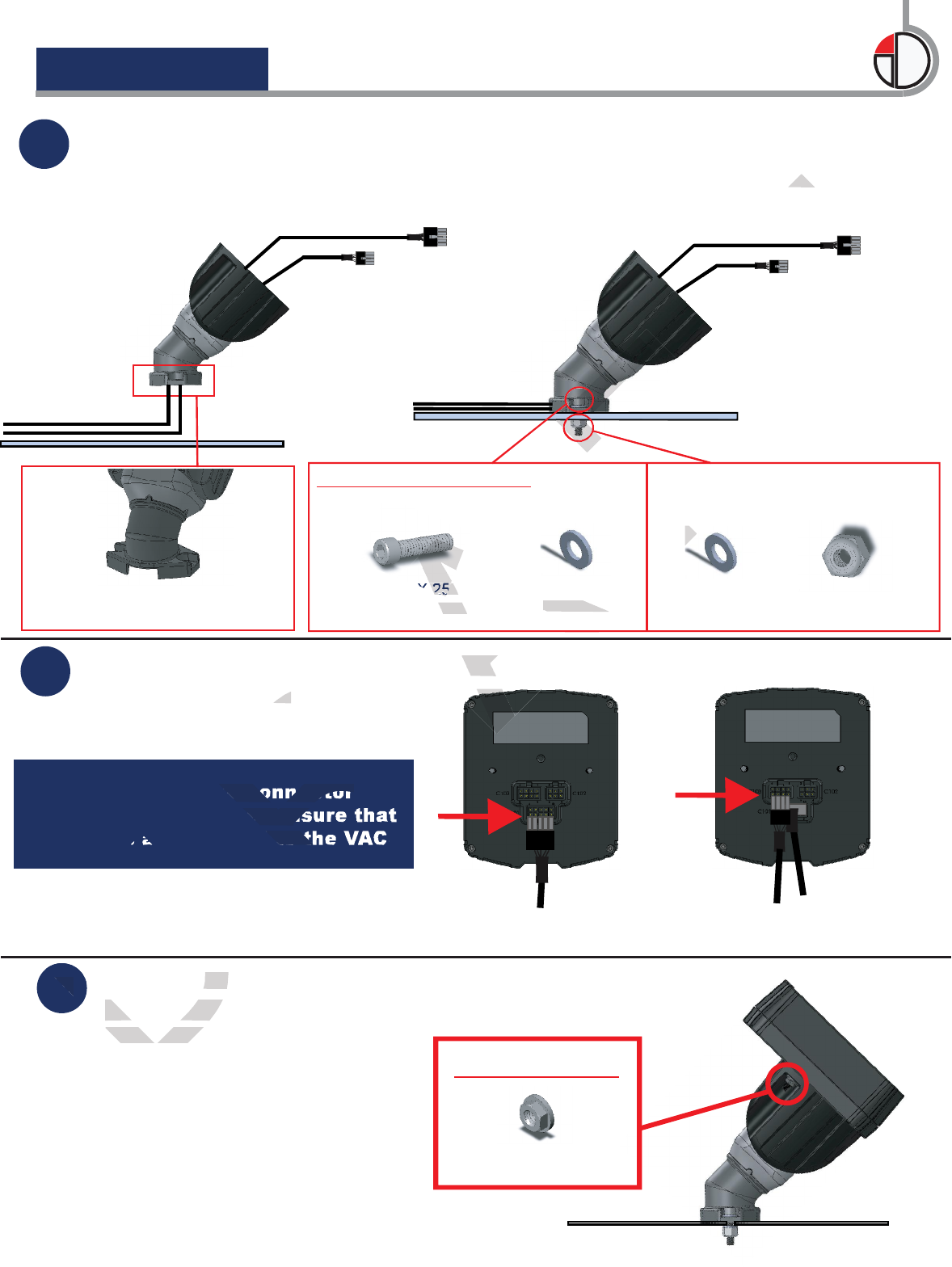
10 Connect the VAC and Impact Sensor cables pin connectors to their
respective ports.
9If the VAC and Impact Sensor cables are being routed along the
mounting surface, route the cables through the slot at the base of the
VAC bracket. Attach the bracket to the vehicle using the supplied
bolts and nuts. Proceed to Step 10.
Use supplied hardware:
11 Slide the VAC onto the bracket and
secure using the supplied nuts and
threaded studs.
Use supplied nuts:
M5 Serrated Hex Nut
M6 X 1.0 X 25 mm
Socket Head Screw
Underside of Vehicle
Mounting Surface
Topside of Vehicle Mounting Surface
M6
Nylon Lock Nut
M6
ID Washer
M6
ID Washer
The 10-pin VAC cable
connector to port C101.
The 8-pin Impact Sensor cable
connector to port C103.
Vehic VAC4 Installation
PowerBoxTM
Note: Verify that the connector
latches are engaged to ensure that
the cables are secured to the VAC.
Slot at base of VAC bracket
to be used for cable routing
D
D
11
Slide the VAC onto the bracket and
Slide the VAC onto the bracket and
secure using the supplied nuts and
secure using the supplied nuts and
threaded studs.threaded studs.
D
D
R
Connect the VAC and Impact Sensor cables pin connectors to their
respective ports.
respective ports.
R
Note: Verify that the connector
latches are engaged to ensure that
the cables are secured to the VAC.
A
Connect the VAC and Impact Sensor cables pin connectors to their
Connect the VAC and Impact Sensor cables pin connectors to their
A
A
M6 X 1.0 X 25 mm
M6 X 1.0 X 25 mm
Socket Head Screw
Socket Head Screw
Topside of Vehicle Mounting Surface
M6
ID Washer
ID Washer
F
F
F
F
F
F
F
F
Underside of Vehicle
Mounting Surface
T
VAC bracket. Attach the bracket to the vehicle using the supplied VAC bracket. Attach the bracket to the vehicle using the supplied
T
T
T
T
T
T
T
T
T
T
T
T
T
T
T
T
T
T
T
T
T
T
T
T
T
T
T
T
T
T
T
T
T
T
T
T
T
T
T
T
085-00000590_01
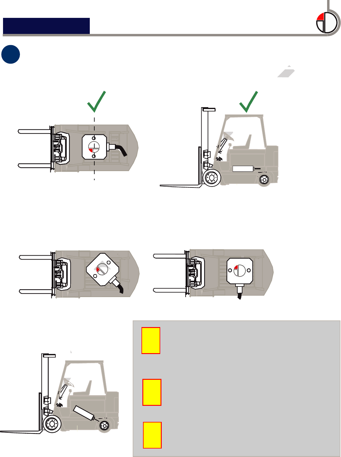
12 Mount the impact sensor at a stable section of the vehicle’s frame.
Select a location that is not prone to vibration or routine shock
and is as close to the center of the vehicle as possible (see below).
XX
X
center of vehicle
Clean the vehicle surface prior to
adhering the impact sensor’s
double-sided tape.
The supplied tape cannot be
reused. If the sensor must be
moved, new tape must be used.
Do not bolt down the impact sensor.
!
!
!
Vehic Mounting the Impact Sensor
PowerBoxTM
D
D
D
D
D
D
D
D
D
D
D
D
D
D
D
D
D
D
D
D
D
D
D
D
D
D
D
D
D
D
D
D
X
X
R
R
R
R
R
R
R
R
R
R
R
R
R
R
R
R
R
R
R
R
R
R
R
R
R
R
R
R
R
R
R
R
R
R
R
R
R
R
R
R
R
R
R
R
R
R
R
R
R
R
R
R
R
R
R
R
R
R
R
R
R
R
R
R
R
R
R
R
R
R
R
R
R
R
R
R
R
A
A
A
A
A
A
A
A
A
A
A
A
A
A
A
A
A
A
A
A
A
A
A
A
A
F
F
F
F
F
F
F
F
F
F
F
F
F
F
F
F
F
F
F
F
F
F
F
F
F
F
F
F
F
F
F
F
F
F
F
F
F
F
F
F
F
F
F
F
F
F
F
F
F
F
F
F
F
F
F
F
F
F
F
F
F
F
F
F
F
F
F
F
F
F
F
F
F
F
F
F
F
F
F
F
F
F
F
F
F
F
F
F
F
F
F
F
F
F
F
F
F
F
F
F
F
F
F
F
F
F
F
F
F
F
F
F
F
F
T
Select a location that is not prone to vibration or routine shock Select a location that is not prone to vibration or routine shock
and is as close to the center of the vehicle as possible (see below).
and is as close to the center of the vehicle as possible (see below).
T
T
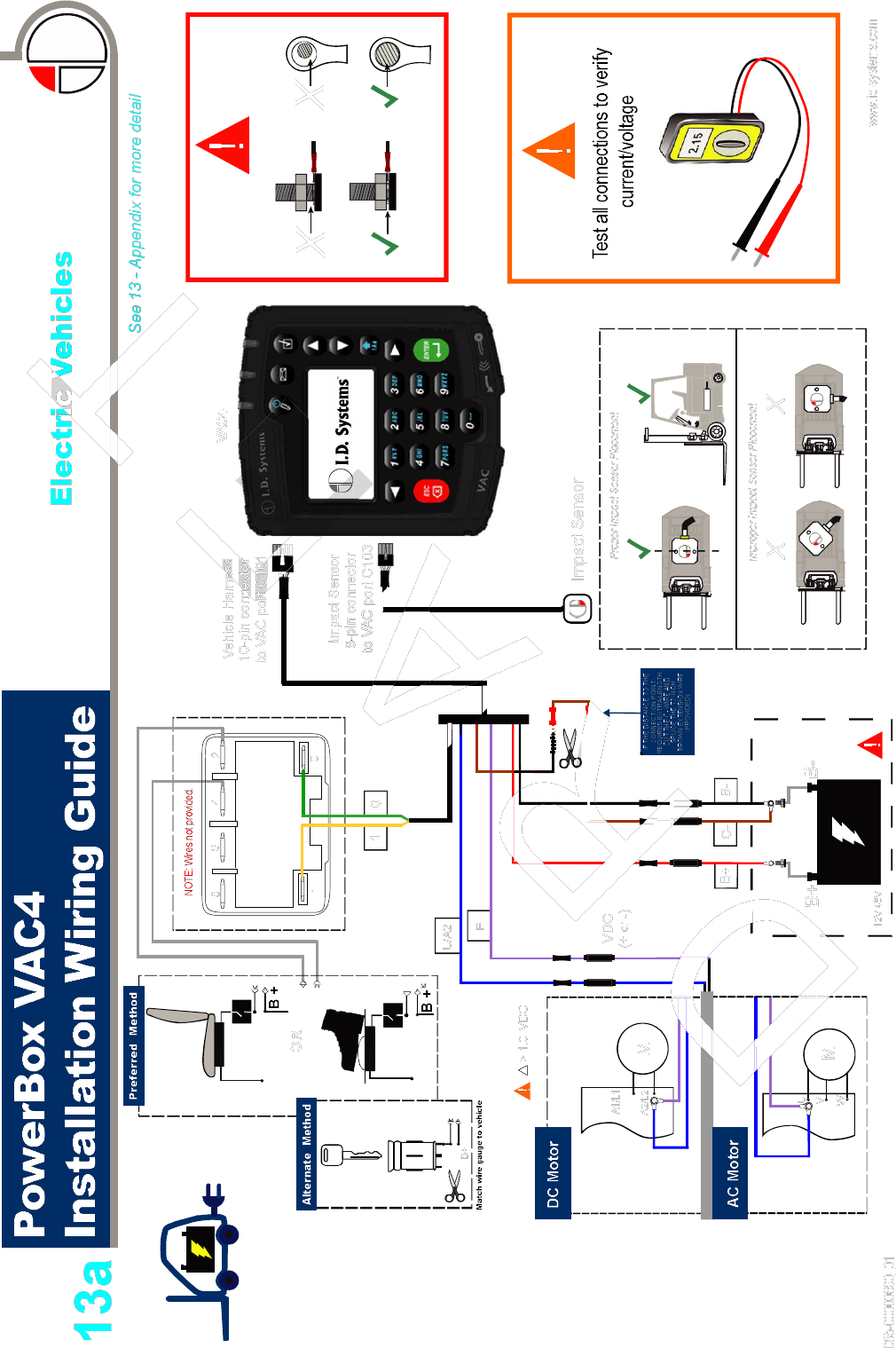
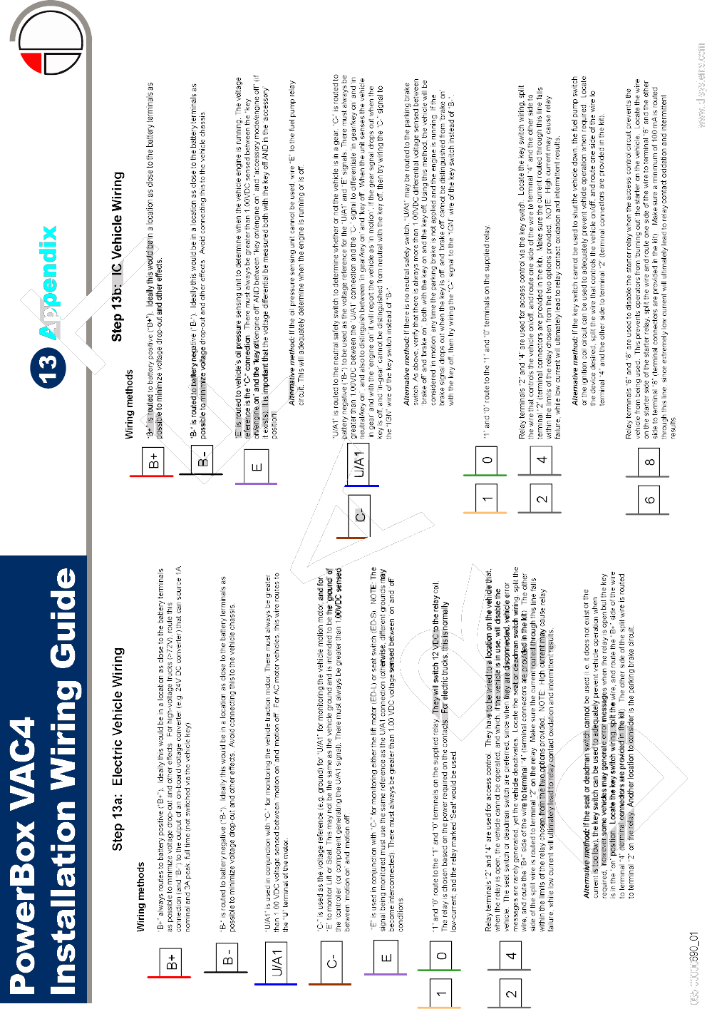
Electric Vehicles Only
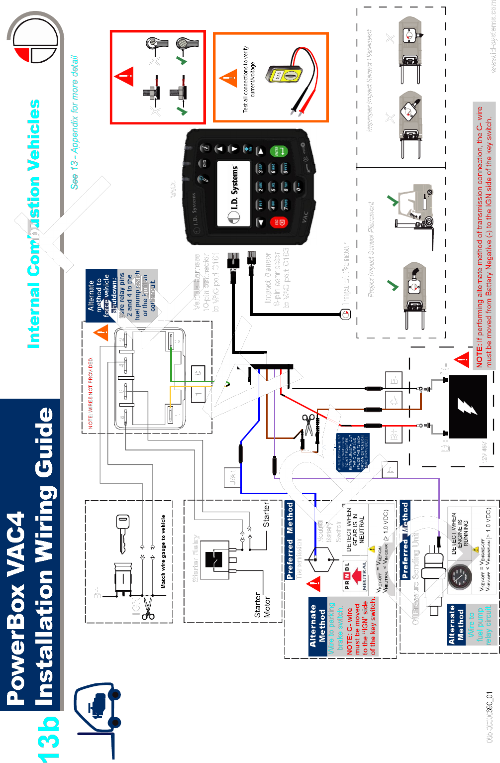
IC Vehicles Only
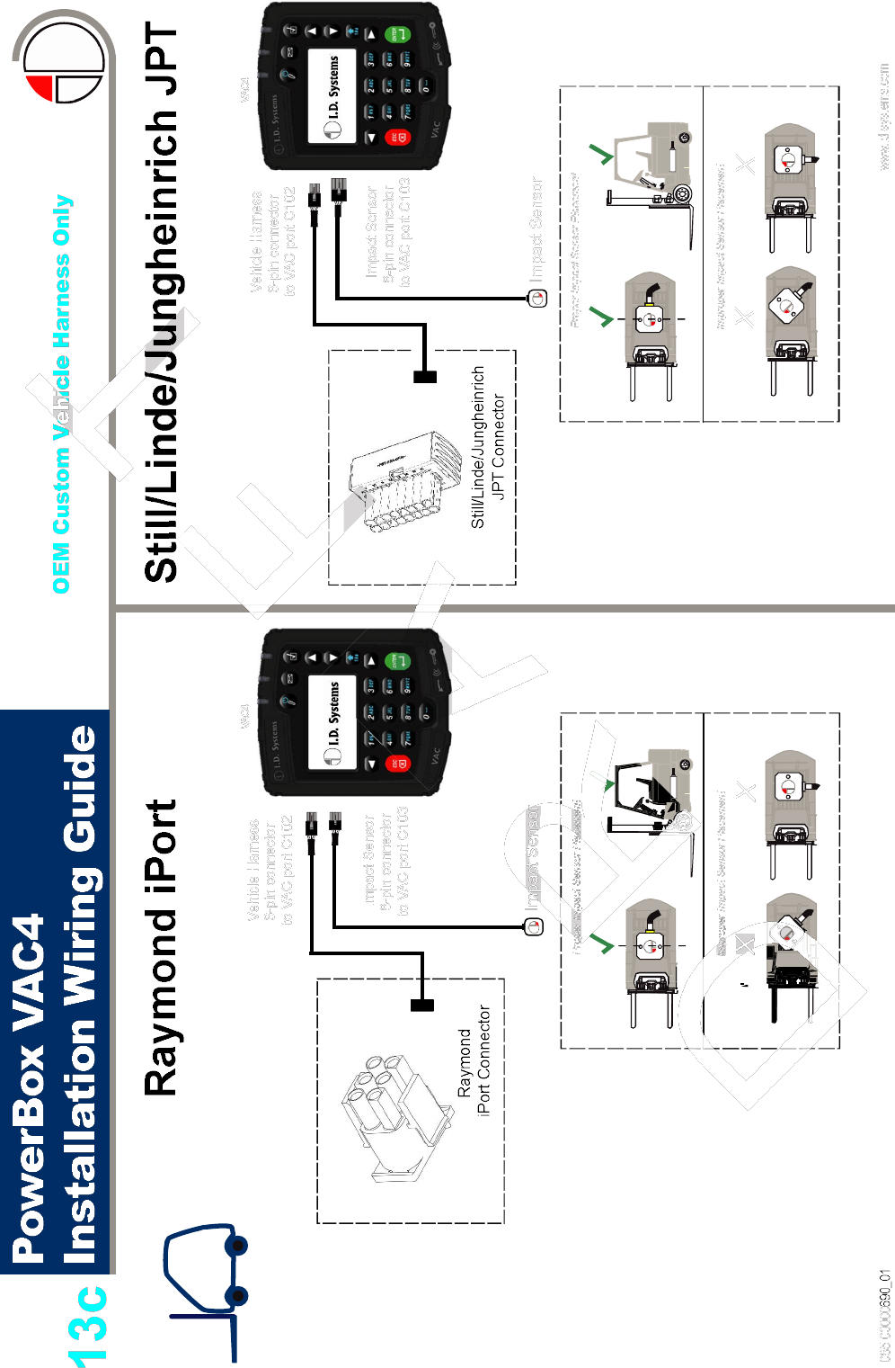
OEM Custom Vehicle
Harness Only