ICOM orporated 217700 VHF/UHF Amateur Transceiver User Manual IC 706MKIIG Instruction Manual
ICOM Incorporated VHF/UHF Amateur Transceiver IC 706MKIIG Instruction Manual
UserManual.wiki
>
ICOM orporated
>
217700 User Manual
Users Manual
Navigation menu
Upload a User Manual
Namespaces
Wiki Guide
HTML
PDF
Info
Views
User Manual
Discussion / Help
Navigation
![EXPLICIT DEFINITIONSPRECAUTIONSIMPORTANTRReeaadd tthhiiss iinnssttrruuccttiioonn mmaannuuaall ccaarreeffuullllyybefore attempting to operate the transceiver.SSaavvee tthhiiss iinnssttrruuccttiioonn mmaannuuaall..This instructionmanual contains important safety and operatinginstructions for the IC-706MKIIG.RWWAARRNNIINNGG HHIIGGHH VVOOLLTTAAGGEE!! NNEEVVEERRattach an antenna or internal antenna connector dur-ing transmission. This may result in an electrical shockor burn.RNNEEVVEERRapply AC to the [DC13.8V] socket on thetransceiver rear panel. This could cause a fire or ruinthe transceiver.RNNEEVVEERRapply more than 16 V DC, such as a 24 Vbattery, to the [DC13.8V] socket on the transceiverrear panel. This could cause a fire or ruin the transceiv-er.RNNEEVVEERRlet metal, wire or other objects touch anyinternal part or connectors on the rear panel of thetransceiver. This will cause electric shock.RNNEEVVEERRexpose the transceiver to rain, snow orany liquids.NNEEVVEERR allow children to play with the transceiver.AAVVOOIIDD using or placing the transceiver in areas withtemperatures below –10°C (+14°F) or above +60°C(+140°F). Be aware that temperatures on a vehicle’sdashboard can exceed 80°C, resulting in permanentdamage to the transceiver’s front panel if left there forextended periods.AAVVOOIIDD placing the transceiver in excessively dustyenvironments or in direct sunlight.AAVVOOIIDD placing the transceiver against walls or puttinganything on top of the transceiver. This will obstructheat dissipation.During mobile operation, DDOO NNOOTToperate the trans-ceiver without running the vehicle’s engine. Whentransceiver power is ON and your vehicle’s engine isOFF, the vehicle’s battery will soon become exhausted.Make sure the transceiver power is OFF before start-ing the vehicle. This will avoid possible damage to thetransceiver by ignition voltage spikes.During maritime mobile operation, keep the transceiv-er and microphone as far away as possible from themagnetic navigation compass to prevent erroneousindications.BBEE CCAARREEFFUULL!!The heatsink will become hot whenoperating the transceiver continuously for long peri-ods.BBEE CCAARREEFFUULL!!If a linear amplifier is connected, setthe transceiver’s RF output power to less than the lin-ear amplifier’s maximum input level, otherwise, the lin-ear amplifier will be damaged.Use Icom microphones only (supplied or optional).Other manufacturer’s microphones have different pinassignments and connection to the IC-706MKIIG maydamage the transceiver.Beat signals may be heard on some frequencies.These will occur as a result of circuit construction.For U.S.A. onlyCCaauuttiioonn::Changes or modifications to this transceiver, notexpressly approved by Icom Inc., could void your authorityto operate this transceiver under FCC regulations.iThe explicit definitions described below apply to thisinstruction manual.WWOORRDDDDEEFFIINNIITTIIOONNRWWAARRNNIINNGGPersonal injury, fire hazard or electricshock may occur.CCAAUUTTIIOONNEquipment damage may occur.NNOOTTEEIf disregarded, inconvenience only. No riskof personal injury, fire or electric shock.IC-706MKIIG.qxd 02.3.27 13:53 Page i](https://usermanual.wiki/ICOM-orporated/217700/User-Guide-317656-Page-2.png)
![■FFrroonntt ppaanneellqPPOOWWEERR SSWWIITTCCHH [[PPOOWWEERR]] (p. 15)Turns power ON and OFF.•Push momentarily to turn power ON.•Push for 2 sec. to turn power OFF.wAAFF GGAAIINN CCOONNTTRROOLL [[AAFF]] (inner control; p. 15)Rotate clockwise to increase the audio output fromthe speaker; rotate counterclockwise to decreasethe audio output from the speaker.eRRFF GGAAIINN CCOONNTTRROOLL//SSQQUUEELLCCHH CCOONNTTRROOLL[[RRFF//SSQQLL]] (outer control; p. 22)➥Adjusts the squelch threshold level (to mutenoise when receiving no signal) in all modes.➥This control can be used for RF gain control toadjust receiver gain manually.•RF gain selection can be set in initial set mode (p. 50).• RF gain is usable in SSB/CW/RTTY modes only.rFFUUNNCCTTIIOONN DDIISSPPLLAAYYShows the operating frequency, dot matrix indica-tions, selected memory channel, etc. See p. 7 fordetails.tTTUUNNIINNGG SSTTEEPP SSWWIITTCCHH [[TTSS]] ((pgs. 17, 18)➥Push momentarily to cycle between 1 Hz/10 Hz,programmable and 1 MHz tuning steps.•1 and 10 Hz steps are only available in SSB, CW andRTTY modes; 1 MHz steps are only available in FM,WFM and AM modes.➥Push for 2 sec. to toggle between 1 and 10 Hzsteps, or; when the programmable tuning steps isindicated, push for 2 sec. to enter programmabletuning step mode.yMMOODDEE SSWWIITTCCHH [[MMOODDEE]] (p. 19)➥Push momentarily to cycle through the operatingmodes:USB/LSB ➧CW/CWå➧RTTY/åRTTY ➧➧FM/WFM/AM➥Push and hold for 2 sec. to toggle between thefollowing operating modes:USB ↔LSBCW ↔CWåRTTY ↔åRTTYFM →WFM →AM →FM, etc.uRREECCEEIIVVEE//TTRRAANNSSMMIITT IINNDDIICCAATTOORRSS [[RRXX]]//[[TTXX]][RX] lights green while receiving (and squelchopens); [TX] lights red while transmitting.iMMAAIINN DDIIAALLChanges the displayed frequency, selects initial setmode items, etc.oUUPP//DDOOWWNN ((BBAANNDD)) SSWWIITTCCHHEESS [[Y//Z((BBAANNDD))]]➥Push to select a band.•Can also be used to advance quick set mode items,initial set mode items, etc.➥Push and hold to scroll through the bands con-tinuously.!0 MMAAIINN DDIIAALL TTEENNSSIIOONN LLAATTCCHHSelects the main dial tension.•2 positions are available.!1 MMIICCRROOPPHHOONNEE CCOONNNNEECCTTOORR (p. 8)Modular-type microphone connector—connectsthe supplied microphone (HM-103).•The optional OPC-589 can be used to connect an 8-pinmicrophone such as the SM-8 or SM-20, if desired.•A microphone connector is also available on the rear11PPAANNEELL DDEESSCCRRIIPPTTIIOONNHF/VHF/UHF TRANSCEIVER i706MK™GAFRIT/SUBMENU F-1 F-2 F-3MODEBANDBANDYZTSDISPLAYLOCKRXTXM-CHPHONESTUNER/CALLP.AMP/ATTPOWERSHIFTRF/SQLqw e rtyioo!1!2!3!4!5!6!7!8!9@0@2@1 !0uCHVFO APOS15537920401060dBUSBM1 SPL A/B A=BIC-706MKIIG.qxd 02.3.27 13:53 Page 1](https://usermanual.wiki/ICOM-orporated/217700/User-Guide-317656-Page-4.png)
![21PANEL DESCRIPTIONpanel. DO NOT connect 2 microphones simultaneously.!2 LLOOCCKK SSWWIITTCCHH [[LLOOCCKK]]➥Push momentarily to turn the dial lock functionON and OFF.•The dial lock function electronically locks the maindial.➥When the optional UT-102 VOICE SYNTHESIZERUNITis installed (p. 52), push for 2 sec. to have thefrequency, etc. announced.•UT-102 operation can be adjusted in initial set mode(pgs. 53, 54).!3 DDIISSPPLLAAYY SSWWIITTCCHH [[DDIISSPP]] (p. 68)➥Push momentarily to select one of the threemenu sets: M1 to M4, S1 to S4 and G1 to G4.➥Push for 2 sec. to select quick set mode.!4FFUUNNCCTTIIOONN SSWWIITTCCHHEESS [[FF11]]//[[FF22]]//[[FF33]] (pgs. 3, 4, 68)Push to select the function indicated in the dotmatrix display above these switches.•Functions vary depending on the menu set selected.!5 MMEENNUU SSWWIITTCCHH [[MMEENNUU]] (p. 68)➥Push this switch one or more times to selectmenus within a menu set (M, Sor G), or push toadvance through the quick set mode and initialset mode displays.➥Push and hold to jump between two differentfunction menu sets.!6 RRIITT//SSUUBB DDIIAALL SSWWIITTCCHH [[RRIITT//SSUUBB]] (p. 20)➥Push to toggle the RIT or SUB DIAL function ONand OFF—initial set mode is used to select thedesired action*.•Lights green when the SUB DIAL function is ON;lights red when the RIT function is ON.•Use the [M-CH] control to vary the RIT frequency orSUB DIAL frequency (see above).➥When the RIT function is ON, push for 2 sec. toadd or subtract the shifted frequency to the oper-ating frequency.*Even if RIT is selected in initial set mode, RIT cannot beselected when operating AM, FM or WFM modes.!7SSHHIIFFTT CCOONNTTRROOLL [[SSHHIIFFTT]] (outer control; p. 20)Shifts the center frequency of the receiver’s IFpassband.•Rotate the control clockwise to shift the center frequen-cy higher, or rotate the control counterclockwise to shiftthe center frequency lower.•When the graphic menu display (G2) is selected, the IFpassband is graphically displayed and changes inaccordance with the [SHIFT] control (see p. 20).!8 MM--CCHH CCOONNTTRROOLL [[MM--CCHH]] (inner control)➥When the RIT or SUBDIAL functions are OFF,rotate to select a memory channel number (p. 35).➥Shifts the receive frequency while the RIT func-tion is ON in SSB, CW and RTTY modes (seebelow and p. 20).•RIT variable range is ± 9.99 kHz➥Changes the operating frequency in the select-ed tuning steps while the SUB DIAL function isON (p. 18).!9 HHEEAADDPPHHOONNEE JJAACCKK [[PPHHOONNEESS]] (p. 12)Accepts headphones with 4–16 Ωimpedance.•When headphones are connected, no receive audiocomes from the speaker.•When the PHONES/SPEAKER switch on the back of thefront panel is set to the [SPEAKER] position, an externalspeaker can be connected. This is convenient for mobileor outdoor operation.@0 TTUUNNEERR//CCAALLLL SSWWIITTCCHH [[TTUUNNEERR//CCAALLLL]](pgs. 26, 27)➥During HF/50 MHz operation, push this switchmomentarily to toggle the automatic antennatuner function ON/OFF.•An optional antenna tuner must be connected.➥During HF/50 MHz operation, push this switch for2 sec. to manually tune the antenna.•An optional antenna tuner must be connected.➥During 144/430 MHz operation, push this switchmomentarily to select the call channel (or the pre-vious channel/frequency when the call channel isalready selected). (p. 39)•“C1” is the 144 MHz call channel and “C2” is the 430MHz call channel.@1FFRROONNTT PPAANNEELL LLAATTCCHH (p. 10)Pull away from the transceiver (towards yourselfwhen looking at the front of the transceiver) todetach the front panel from the main body of thetransceiver.@2PPRREEAAMMPP//AATTTTEENNUUAATTOORR SSWWIITTCCHH [[PP..AAMMPP//AATTTT]](p. 21)➥Push momentarily to turn the preamp ON or OFF.➥Push and hold to turn the 20 dB attenuator ON;push momentarily to turn the attenuator OFF.•Lights green when the preamp is ON; lights red whenthe 20 dB attenuator is ON.LOCKLights while the lockfunction is activated.RITSUBLights red while the RIT function is activated;green while the SUB DIAL function is activated.TUNER/CALLLights while the automatictuning function is activated.P.AMP/ATTLights green while the preamp is activated;lights red while the attenuator is activated.IC-706MKIIG.qxd 02.3.27 13:53 Page 2](https://usermanual.wiki/ICOM-orporated/217700/User-Guide-317656-Page-5.png)
![■FFuunnccttiioonn sswwiittcchheessDMM11 FFUUNNCCTTIIOONNSSSSPPLLIITT OOPPEERRAATTIIOONN (p. 29)Toggles the split function ON and OFF.•“ä”appears when the split function is ON.•The function of [F-3] changes to XFC when thesplit function is ON.VVFFOO AA//BB SSEELLEECCTTIIOONN(p. 16)➥Toggles between VFO A and VFO B inVFO mode.➥Toggles between transmission VFO andreception VFO during split operation.➥Toggles between the transmit andreceive frequencies (and modes) ofmemory channels when the split func-tion is turned ON.VVFFOO EEQQUUAALLIIZZAATTIIOONN (p. 16)Equalizes the frequency and operatingmode of the two VFO’s.•The rear (undisplayed) frequency and operat-ing mode are equalized to the front (displayed)VFO frequency and operating mode.TTRRAANNSSMMIITT FFRREEQQUUEENNCCYY CCHHEECCKK (p. 29)Appears when the split function is turnedON—monitors the transmit frequencywhen pushed and held.•While pushed, the transmit frequency can bechanged with the main dial.DMM22 FFUUNNCCTTIIOONNSSMMEEMMOORRYY WWRRIITTEE (p. 40)Stores the displayed frequency and oper-ating mode into the displayed memorychannel.MMEEMMOORRYY TTRRAANNSSFFEERR (p. 41)Transfers the frequency and operatingmode in the selected memory channel to aVFO.VVFFOO//MMEEMMOORRYY (p. 39)Toggles between VFO and memorymodes.MMEEMMOORRYY CCLLEEAARR (p. 39)Clears the selected memory channel’scontents.•“}” appears.DMM33 FFUUNNCCTTIIOONNSSNNAARRRROOWW FFIILLTTEERR (p. 23)Toggles the narrow filter (or widefilter—push for 2 sec.) ON and OFF.•“ã”appears when the narrow filter is ON; “ç”appears when the wide filter is ON.•An optional narrow filter and presetting in initialset mode (p. 51) is necessary to use the fol-lowing:CW/RTTY narrow: FL-100, FL-101 or FL-232SSB narrow: FL-223SSB wide: FL-103NNOOIISSEE BBLLAANNKKEERR (p. 21)Turns the noise blanker ON and OFF.•The noise blanker does not function in FM andWFM modes; the “AM Noise blanker” item ininitial set mode must be set to ON for the noiseblanker to work in AM mode (p. 53).MMEETTEERR SSEELLEECCTTIIOONN(p. 25)Selects the type of meter displayed (dur-ing transmit) in the function display.•Power, ALC or SWR metering can be selected.•Only an S-meter is available for receive.DMM44 FFUUNNCCTTIIOONNSSDURING SSB/AM OPERATION:DURING CW OPERATION:DURING RTTY OPERATION:DURING FM OPERATION:F-3METF-2NBF-1FILF-2MCLF-3V/MF-2MÜVF-1MWF-3XFCF-3A=BF-2A/BF-1SPL31PANEL DESCRIPTIONMENUM3F-1FILF-2NBF-3METMENUM4F-1VOXF-2COMF-3AGCMENUM4F-1 F-2BRKi/4F-3AGCMENUM2F-1MWF-2MÜVMCL F-3V/M(in memory mode)MENUM4F-11/4F-2 F-3AGCMENUM4F-1VOXF-2TSQF-3TONMENUM1F-1SPLF-2A/BXFCF-3A=BIC-706MKIIG.qxd 02.3.27 13:53 Page 3](https://usermanual.wiki/ICOM-orporated/217700/User-Guide-317656-Page-6.png)
![41PANEL DESCRIPTIONVVOOXX FFUUNNCCTTIIOONN (p. 26)Toggles the VOX function ON and OFF.•The [VOX GAIN] and [ANTI VOX] are availableon the side panel.•VOX delay can be set in quick set mode(p. 48).SSPPEEEECCHH CCOOMMPPRREESSSSOORR (p. 26)Toggles the speech compressor ON andOFF.•The [COMP GAIN] control is available on theside panel.AAGGCC (p. 21)Changes the time constant of the AGC cir-cuit.BBRREEAAKK--IINN (p. 33)Selects semi break-in, full break-in (QSK)and break-in OFF•“BK” or “F-BK” appears when selecting semibreak-in or full break-in, respectively.•An external switch, such as a foot switch, isnecessary to connect to the ACC socket (pin3, pin 7 or RTTY SEND—see p. 35) to use nobreak-in operation.11//44 FFUUNNCCTTIIOONN (p. 36)Toggles the 1/4 function ON and OFF.•When the 1⁄4function is ON, a bar appearsunder the 1⁄4indication and fine tuning can beused.TTOONNEE SSQQUUEELLCCHH (p. 31)Toggles the tone squelch function ON andOFF (a tone squelch frequency must beselected in Quick Set mode).•“FM-TSQL” appears when the function is ON.RREEPPEEAATTEERR TTOONNEE OOPPEERRAATTIIOONN (p. 30)➥Toggles the subaudible tone encoderfor repeater use ON and OFF.•“FM-T” appears when the function is ON.➥Transmits a 1750 Hz tone burst whenpushed and held during transmission.•Tone frequencies or tone burst can be set ininitial set mode (p. 49).DSS11 FFUUNNCCTTIIOONNSSMMEEMMOORRYY WWRRIITTEE (p. 40)Stores the displayed frequency and oper-ating mode into the displayed memorychannel.MMEEMMOO PPAADD WWRRIITTEE (p. 42)Stores the displayed frequency and oper-ating mode into a memo pad.MMEEMMOO PPAADD RREEAADD (p. 42)Calls up a memo pad.DSS22 FFUUNNCCTTIIOONNSSSSCCAANN (p. 44)Starts and stops the scan function.PPRRIIOORRIITTYY WWAATTCCHH (p. 44)Starts and stops priority watch.SSEELLEECCTT SSCCAANN (p. 44)Toggles the select setting ON and OFF forthe selected memory channel.VVFFOO//MMEEMMOORRYY (p. 44)Toggles between VFO and memorymodes.DSS33 FFUUNNCCTTIIOONNSSQQUUIICCKK BBAANNDD CCHHAANNGGEE FFUUNNCCTTIIOONN (p. 19)This item provides access to the band stacking regis-ter. By default the 7, 50 and 144 MHz bands are dis-played. Push [F-1] to [F-3] for 2 sec. to select a newband if desired.•A mode is memorized along with the frequency for eachband.DSS44 FFUUNNCCTTIIOONNSS (may be optional for some ver.)AAUUTTOOMMAATTIICC NNOOTTCCHH FFIILLTTEERR (p. 24)This function automatically attenuates beattones, tuning signals, etc., even if they aremoving.NNOOIISSEE RREEDDUUCCTTIIOONN (p. 24)This function reduces noise componentsand picks out desired signals which areburied in the noise.NNOOIISSEE RREEDDUUCCTTIIOONN DDIISSPPLLAAYY (p. 24)This displays the noise reduction levelwhen using the noise reduction function.F-3NRLF-2NRF-1ANFF-3V/MF-2SELF-2PRIF-1SCNF-3MPRF-2MPWF-1MWF-3TONF-2TSQF-11/4F-2BRKF-3AGCF-2COMF-1VOXMENUS1F-1MWF-2MPWF-3MPRMENUS2F-1SCNF-2PRISELF-3V/M(in memory mode)MENUS3F-17F-250F-3144MENUS4F-1ANFF-2NRF-3NRLIC-706MKIIG.qxd 02.3.27 13:53 Page 4](https://usermanual.wiki/ICOM-orporated/217700/User-Guide-317656-Page-7.png)
![51PANEL DESCRIPTION■RReeaarr aanndd ssiiddee ppaanneellssqGGRROOUUNNDD TTEERRMMIINNAALL [[GGNNDD]] (p. 9)Connect this terminal to a ground to prevent electri-cal shocks, TVI, BCI and other problems.wAANNTTEENNNNAA CCOONNNNEECCTTOORRSS [[AANNTT 11]],, [[AANNTT 22]] (p. 11)Accept a 50 Ωantenna with an PL-259 type plug.•[ANT 1] is for connection to an HF/50 MHz antenna.•[ANT 2] is for connection to 144 MHz antenna.•These connectors are switched above or below 60 MHz.eDDAATTAA JJAACCKK [[DDAATTAA]] (p. 12)6-pin min DIN jack to connect a TNC, etc. for packetoperation.rAACCCCEESSSSOORRYY SSOOCCKKEETT [[AACCCC]] (p. 6)Enables connection to external equipment such asa TNC for data communications, a linear amplifier oran automatic antenna selector/tuner, etc.•See page at right for socket information.tRRTTTTYY JJAACCKK [[RRTTTTYY]] (p. 35)Connects an external terminal unit for RTTY (FSK)operation.•The keying polarity and mark/shift frequencies can beselected in quick set mode (p. 48).yCCII--VV RREEMMOOTTEE CCOONNTTRROOLL JJAACCKK [[RREEMMOOTTEE]](p. 45)Designed for use with a personal computer forremote operation of transceiver functions.uMMIICCRROOPPHHOONNEE CCOONNNNEECCTTOORR [[MMIICC]] (p. 11)Accepts the supplied microphone (connected inparallel with the front panel’s [MIC] connector).•See pgs. 1 and 2 for microphone notes.•See p. 8 for microphone connector information.iEELLEECCTTRROONNIICC KKEEYYEERR JJAACCKK [[KKEEYY]] (p. 33)Accepts a paddle to activate the internal electronickeyer.•Selection between the internal electronic keyer andstraight key operation can be made in quick set mode.(p. 49)oDDCC PPOOWWEERR SSOOCCKKEETT [[DDCC1133..88VV]] (p. 13)Accepts 13.8 V DC through the supplied DC powercable.!0EEXXTTEERRNNAALL SSPPEEAAKKEERR JJAACCKK [[EEXXTT SSPP]] (p. 12)Accepts a 4–16 Ωspeaker.!1TTUUNNEERR CCOONNTTRROOLL SSOOCCKKEETT [[TTUUNNEERR]] (p. 12)Accepts the control cable from an optional AH-3 HFAUTOMATIC ANTENNA TUNER.!2SSPPEEEECCHH CCOOMMPPRREESSSSIIOONN LLEEVVEELL CCOONNTTRROOLL[[CCOOMMPP GGAAIINN]] (p. 26)Adjusts the compression level.•This control is available only when the speech compres-sor is ON.COMPGAIN /SIDE TBEEPDC 13.8VEXT SPMIC KEYTUNERANT 1ANT 2GNDqwer uio!2 !3!0!1tyWhen connectinga straight keyWhen connectinga paddle(dot)(com)(dash)(⊕)Rear panel viewRecommendedlevelCounterclockwisedecreases ClockwiseincreasesCOMPGAIN /SIDE TBEEPIC-706MKIIG.qxd 02.3.27 13:53 Page 5](https://usermanual.wiki/ICOM-orporated/217700/User-Guide-317656-Page-8.png)
![•AACCCC SSOOCCKKEETT•WWhheenn ccoonnnneeccttiinngg tthhee AACCCC ccoonnvveerrssiioonn ccaabbllee ((OOPPCC--559999))61PANEL DESCRIPTION!3BBEEEEPP//SSIIDDEETTOONNEE CCOONNTTRROOLL [[BBEEEEPP//SSIIDDEETTOONNEE]] Adjusts the beep tone and CW side tone audio lev-els.TECHNICAL INFORMATIONAACCCCPPIINN ##NNAAMMEEDDEESSCCRRIIPPTTIIOONNSSPPEECCIIFFIICCAATTIIOONNSSCCOOLLOORR18 V Regulated 8 V output. Output voltage : 8 V ±0.3 VOutput current : Less than 10 mA brown2GND Connects to ground. red3 HSENDInput/output pin (HF/50 MHz).Goes to ground when transmitting.When grounded, transmits (connected to 8Vline thru 2.2 kΩresistance/144 MHz operation).Ground level : –0.5 V to 0.8 VInput current : Less than 20 mA(HF/50 MHz bands)orange4 BDT Data line for the optional AT-180. yellow5BAND Band voltage output.(Varies with amateur band) Output voltage : 0 to 8.0 V green6ALC ALC voltage input. Control voltage : –4 to 0 VInput impedance : More than 10 kΩblue7VSENDInput/output pin (144 MHz).Goes to ground when transmitting.When grounded, transmits (connected to 8Vline thru 2.2 kΩresistance/HF•50 MHz operation).Ground level : –0.5 V to 0.8 VInput current : Less than 20 mA(144 MHz band)purple813.8 V 13.8 V output when power is ON. Output current :Max. 1 A gray9TKEY Key line for the AT-180. white10 FSKK RTTY keying input.Connected in parallel to the [RTTY] jack.Ground level : –0.5 to 0.8 VInput current : Less than 10 mA black11 MOD Modulator input.Input impedance : 10 kΩInput level : Approx. 100 mVrmspink12 AF AF detector output.Fixed, regardless of [AF] position.Output impedance : 4.7 kΩOutput level : 100 to 350 mV rmslightblue13 SQLS Squelch output.Goes to ground when squelch opens.SQL open : Less than 0.3 V/5 mASQL closed : More than 6.0 V/100 µAlightgreenRear panelview12348765910 11 1213Color refers to thecable strands of thesupplied cable.ACC 1ACC 2➀ FSKK ➄ AF➁ GND ➅ SQLS➂ HSEND ➆ 13.8 V➃ MOD ➇ ALC➀ 8 V ➄ ALC➁ GND ➅ VSEND➂ HSEND ➆ 13.8 V➃ BAND1122334488776655910 11 12131234765IC-706MKIIG.qxd 02.3.27 13:53 Page 6](https://usermanual.wiki/ICOM-orporated/217700/User-Guide-317656-Page-9.png)
![71PANEL DESCRIPTION■FFuunnccttiioonn ddiissppllaayyqNNAARRRROOWW//WWIIDDEE FFIILLTTEERR IINNDDIICCAATTOORRSS➥“ã” appears when selecting AM narrow or FMnarrow modes.➥When installing an optional narrow filter, narrowmode can be selected in CW, RTTY and SSBmodes.•When the SSB wide filter is installed, “ç” appearsduring wide mode selection.wMMOODDEE IINNDDIICCAATTOORRSSShow the operating mode.ePPRROOGGRRAAMMMMAABBLLEE//11 MMHHzz TTUUNNIINNGG SSTTEEPPIINNDDIICCAATTOORRSS➥➌a appears when the programmable tuning stepis selected.➥➌b appears when the 1 MHz tuning step isselected.rSSPPLLIITT IINNDDIICCAATTOORRShows that the split frequency function is activated.tFFRREEQQUUEENNCCYY RREEAADDOOUUTTShows the operating frequency.•“C” appears in place of the 1 Hz digit when the call chan-nel is selected.yDDUUPPLLEEXX IINNDDIICCAATTOORRSS➥“DUP+” appears during plus duplex operation.➥“DUP–” appears during minus duplex operation.uBBLLAANNKK IINNDDIICCAATTOORRShows that the displayed memory channel is notprogrammed.•This indicator appears both in VFO and memory modes.iVVFFOO//MMEEMMOORRYY IINNDDIICCAATTOORRSSVFO A or B appears when VFO mode is selected;MEMO appears when memory mode is selected.oSSEELLEECCTT IINNDDIICCAATTOORRShows that the displayed memory channel is desig-nated as a select memory channel.!0 MMEEMMOORRYY CCHHAANNNNEELL NNUUMMBBEERR RREEAADDOOUUTTShows the selected memory channel number.!1 DDOOTT MMAATTRRIIXX IINNDDIICCAATTOORRSSThese alphanumeric readouts show a variety ofinformation such as current functions of the “F”keys [F1] to [F3], memory channel names, set modeitems, etc. See p. 68 for an overview of these indi-cators.!2 MMEETTEERR RREEAADDOOUUTTSS➥Functions as an S-meter while receiving.➥Functions as a power, ALC or SWR meter whiletransmitting.NNoottee::The SWR meter does not function in the 144MHz band.!3 FFUUNNCCTTIIOONN IINNDDIICCAATTOORRSS➥“NB” appears when the noise blanker is activat-ed.➥“VOX” appears when the VOX function is select-ed.➥“F-BK” appears when full break-in operation isselected and only “BK” appears when semibreak-in operation is selected.➥“COM” appears when the speech compressor isactivated.➥“FAGC” appears when the fast AGC function isselected.!4 DDSSPP IINNDDIICCAATTOORRSSAppear when the optional DSP unit is installed andactivated.N W R SPLLSBDSPNB VOX F-BK COM FSCHVFO ADUPVFO BMEMOAGCALCSWR POS11 1.5 2 3 55379204010∞60dBUSBCW RTTYAMWFM TSQLBLANKANFNRqw rtyuo!1!2!3!4i!0eaebM1 SPL A/B A=BIC-706MKIIG.qxd 02.3.27 13:53 Page 7](https://usermanual.wiki/ICOM-orporated/217700/User-Guide-317656-Page-10.png)
![•MMIICCRROOPPHHOONNEE CCOONNNNEECCTTOORR81PANEL DESCRIPTION■MMiiccrroopphhoonnee ((HHMM--110033))qUUPP//DDOOWWNN SSWWIITTCCHHEESS [[UUPP]]//[[DDNN]]Change the operating frequency.•Push and hold to change the frequency continuously.•Tuning step is 50 Hz when no TS indicator appears.wLLOOCCKK SSWWIITTCCHH [[LLOOCCKK]]Locks the [UP]/[DN] switches.ePPTTTT SSWWIITTCCHH [[PPTTTT]]Push and hold to transmit; release to receive.DN UPLOCKOFF ON➊➋➌TECHNICAL INFORMATIONPPIINN NNOO..FFUUNNCCTTIIOONNDDEESSCCRRIIPPTTIIOONN1+8 V DC output Max. 10 mA2Frequency up GroundFrequency down Ground through 470 Ω8Squelch open “LOW” levelSquelch closed “HIGH” level➃ PTT➅ Microphone input➁ Frequency up/down➆ GND➀ +8 V DC output ➇ Squelch switch➄ GND (microphone ground)➂ AF outputRear panel view1 2345678•HHMM--110033 SSCCHHEEMMAATTIICC DDIIAAGGRRAAMM4700p4700p10µ0.33µ++MICROPHONEMICELEMENT2k2.2k470DOWN UPPTT RECEIVETRANSMITMICROPHONECABLEMICROPHONE PLUG12345678CCaauuttiioonn::DO NOT short pin 1 to ground asthis can damage the internal 8 V regulator.IC-706MKIIG.qxd 02.3.27 13:53 Page 8](https://usermanual.wiki/ICOM-orporated/217700/User-Guide-317656-Page-11.png)
![92IINNSSTTAALLLLAATTIIOONN AANNDD CCOONNNNEECCTTIIOONNSS■UUnnppaacckkiinnggAfter unpacking, immediately report any damage tothe delivering carrier or dealer. Keep the shipping car-tons.For a description and a diagram of accessory equip-ment included with the IC-706MKIIG, see UNPACK-ING on p. ii of this manual.■GGrroouunnddiinnggTo prevent electrical shock, television interference(TVI), broadcast interference (BCI) and other prob-lems, ground the transceiver through the GROUNDterminal on the rear panel.For best results, connect a heavy gauge wire or strapto a long earth-sunk copper rod. Make the distancebetween the GROUND terminal and ground as shortas possible.■AAnntteennnnaaSelect antenna(s), such as a well-matched 50 Ωantenna, and feedline. The transmission line shouldbe a coaxial cable. 1.5 : 1 or better of VoltageStanding Wave Ratio (VSWR) is recommended foryour required band. Of course, the transmission lineshould be a coaxial cable.CCAAUUTTIIOONN::Protect your transceiver from light-ning using a lightning arrestor.RWWAARRNNIINNGG::NNEEVVEERR connect the [GND]terminal to a gas or electric pipe, since the connec-tion could cause an explosion or electric shock.30 mm10 mm (soft solder)10 mm1–2 mmsolder solderSoftsolderCoupling ringPL-259 CONNECTOR INSTALLATION EXAMPLE➀➂➃➁Slide the coupling ring down. Strip the cable jacket and soft solder.Slide the connector body on and solder it.Screw the coupling ring onto the connector body.Strip the cable as shown at left. Soft solder the center con-ductor.(10 mm ≈ 3⁄8 in)AANNTTEENNNNAA SSWWRREach antenna is tuned for a specified frequencyrange and SWR may be increased out-of-range.When the SWR is higher than approx. 2.0 : 1, thetransceiver’s power drops to protect the final transis-tors. In this case, an optional antenna tuner is usefulto match the transceiver and antenna. Low SWRallows full power for transmitting even when usingthe antenna tuner. The IC-706MKIIG has an SWRmeter to monitor the antenna SWR continuously.IC-706MKIIG.qxd 02.3.27 13:53 Page 9](https://usermanual.wiki/ICOM-orporated/217700/User-Guide-317656-Page-12.png)

![122INSTALLATION AND CONNECTIONS■AAddvvaanncceedd ccoonnnneeccttiioonnssDC 13.8VEXT SPMIC KEYTUNERANT 1ANT 2GNDOPC-589 (p. 65)DESKTOP (p. 64)MICROPHONE SPEAKERSelectable with the[PHONE/SPEAKER] switchon the back of the front panel.ACC SOCKET (p. 6)REMOTE (p. 45)Used for computer control and transceive.DATA JACK (p. 37)6-pin mini DIN jack to connect to aTNC, etc. for packet operation.AH-3 (p. 14)AH-2bCOAX ANTENNASWITCHEXTERNALSPEAKER (p. 65)HEADPHONESSP-21When using a 50 MHz antenna separately since the AH-3 can only be used for the HF bands.orHF/VHF/UHF TRANSCEIVER i706MK™GAFRIT/SUBMENU F-1 F-2 F-3MODE YZTSDISPLAYLOCKRXTXM-CHPHONESTUNER/CALLP.AMP/ATTPOWERSHIFTRF/SQLBANDBANDIC-706MKIIG.qxd 02.3.27 13:53 Page 12](https://usermanual.wiki/ICOM-orporated/217700/User-Guide-317656-Page-15.png)
![CONNECTING THE PS-125 / PS-85 DC POWER SUPPLYPS-125 / PS-85Connect to an AC outletusing the supplied AC cable.DC power cableDC powersocketCONNECTING A NON-ICOMDC POWER SUPPLY (For Europe versions)TransceiverDC power socketTo non-Icompower supply[GND]OPC-639CONNECTING A NON-ICOMDC POWER SUPPLYTransceiverDC powersocketTo AC outletSuppliedDC power cable13.8 VBlack30 A fusesRed20 A132INSTALLATION AND CONNECTIONS■PPoowweerr ssuuppppllyy ccoonnnneeccttiioonnssUse the optional PS-125 / PS-85 DC POWER SUPPLYwhen operating the IC-706MKIIG with AC power.Refer to the diagram below for connection.CCAAUUTTIIOONN::Before connecting the DC powercable, check the following important items. Makesure:•The [POWER] switch is OFF.•Output voltage of the power source is 12–15 Vwhen you use a non-Icom power supply.•DC power cable polarity is correct.Red : positive (+) terminalBlack : negative (–) terminalGrommetCONNECTING A VEHICLE BATTERYNEVER connect toa 24 V battery.Note: Use terminals forthe cable connections.CrimpSolderSuppliedDC power cableredblack12 VbatteryNNoottee::When using the PS-125, the IC-706MKIIG Europe version complies withEMC directives even if the OPC-639 isnot used.IC-706MKIIG.qxd 02.3.27 13:53 Page 13](https://usermanual.wiki/ICOM-orporated/217700/User-Guide-317656-Page-16.png)
![142INSTALLATION AND CONNECTIONS■EExxtteerrnnaall aanntteennnnaa ttuunneerrss aanndd lliinneeaarr aammpplliiffiieerrAH-4ANT 1TransceiverCoaxial cable(from the AH-4)To the AH-2b oran antenna elementCONNECTING THE AH-4The AH-4 can be used for the HF bands and 50 MHz band only.CONNECTING THE AT-180GroundHFto 6 mantenna[TRANSCEIVER][ANT 1] [ACC] [ACC]AT-180ACC cable supplied with the AT-180Coaxial cable suppliedwith the AT-180IC-706one of twoconnectorsACC-1 REMOTEINPUT-1 ANT1ANTMini-plug cableACC cable7-pin sideAC outlet (220–240 V)IC-PW1GNDGNDACC REMOTETransceiverCoaxial cableTo anantenna OPC-599 conversion cableCONNECTING THE IC-PW1NNoottee::•Turn the IC-706MKIIG’s powerOFF when connecting the AT-180, otherwise, the CPU maymalfunction and the AT-180may not function properly.•The OPC-742 is required whenusing bbootthhthe AT-180 and a 2m linear amplifier.DDoo nnoottconnect [ANT 2] to theAT-180. When using an HF to 2 mwide antenna, use a duplexerbetween the AT-180 and antennasince 2 m signals do not passthrough the AT-180.[ANT 1]TransceiverDuplexerHF to 2 mantennaAT-180[ANT 2]IC-706MKIIG.qxd 02.3.27 13:53 Page 14](https://usermanual.wiki/ICOM-orporated/217700/User-Guide-317656-Page-17.png)
![153FFRREEQQUUEENNCCYY SSEETTTTIINNGG■WWhheenn ffiirrsstt aappppllyyiinngg ppoowweerr ((CCPPUU rreesseettttiinngg))Before first applying power, make sure all connectionsrequired for your system are complete by referring tosection 2. Then, reset the transceiver using the fol-lowing procedure.➀Make sure the transceiver power is OFF.➁While pushing [Y] and [Z], push [POWER] to turnpower ON.•The internal CPU is reset.•The transceiver displays as shown at right when reset-ting is complete.DM1 ddiissppllaayy sseelleeccttiioonnIf you can’t figure out how to return to the M1 display:While pushing [MENU], turn power ON.■IInniittiiaall sseettttiinnggssAfter resetting the transceiver, set controls andswitches as shown in the diagram below.NNoottee::Resetting clears all programmed contents inmemory channels and returns all initial set mode andquick set mode contents to their default values.BLANKCHVFO AS1 5379204060dBUSBM1 SPL A/B A=BThe transceiver displaysits initial frequency andmode.[POWER][Y][Z]PO510[AF]: Max. CCW[RF/SQL]: Max. CCW[LOCK]: OFF(indicator light out)[POWER]: OFF[SHIFT]: Center[P.AMP/ATT]: OFF(indicator lights out)[TUNER/CALL]: OFF(indicator lights out)[RIT/SUB]: OFF(indicator lights out)CCW: counterclockwiseTurn power ON, then check the display. If any of thefollowing indicators appear, turn them OFF as follows:•Tuning step indicators, Z, (SSB, CW or RTTY):Push [TS].•MHz tuning step indicator, Z, (FM, WFM or AM):Push [TS].•1 Hz frequency readout (SSB, CW or RTTY):Push and hold [TS].•Memory mode indicator, MEMO:Use [(F-3)V/M] in the M2 display (p. 68).•Split indicator, ä:Use [(F-1)SPL] in the M1 display (p. 68).IC-706MKIIG.qxd 02.3.27 13:53 Page 15](https://usermanual.wiki/ICOM-orporated/217700/User-Guide-317656-Page-18.png)
![163FREQUENCY SETTING■VVFFOO ddeessccrriippttiioonn VFO is an abbreviation of Variable FrequencyOscillator, and traditionally refers to an oscillator. TheIC-706MKIIG’s VFO can store a frequency and anoperating mode.You can call up a desired frequency to a VFO with thememo pad-read switch (p. 42) or with the memorytransfer switch (p. 42). You can also change the fre-quency with the main dial and select an operatingmode with the [MODE] switch or call up previouslyaccessed frequency and modes with the band stack-ing register (p. 19).The IC-706MKIIG has two VFOs, specially suited forsplit frequency operation. The VFOs are called VFO Aand VFO B. You can use the desired VFO to call up afrequency and operating mode for operation.CHVFO AUSBM1 SPL A/B A=BVFO MODESWITCHMEMORYCHANNELDIALMEMO PAD28.025 MHz 7.001 MHz21.295 MHzBANDSelectChangeTransferTransferTransfer•TThhee ddiiffffeerreenncceess bbeettwweeeenn VVFFOO aanndd mmeemmoorryy mmooddeeVVFFOO MMOODDEEEach VFO shows a frequency and operating mode. Ifthe frequency or operating mode is changed, theVFO automatically memorizes the new frequency oroperating mode.When the VFO is selected from another VFO ormemory mode, the last-used frequency and operat-ing mode for that VFO appear.[[EEXXAAMMPPLLEE]]MMEEMMOORRYY MMOODDEE (pgs. 39–42)Each memory channel shows a frequency and oper-ating mode like a VFO. Even if the frequency ormode is changed, the memory channel does notmemorize the new frequency or memory mode.When a memory channel is selected from anothermemory channel or VFO mode, the memorized fre-quency and operating mode appear.[[EEXXAAMMPPLLEE]]CHVFO AUSBCHVFO AUSBVFO is selected.The frequency is changed.MEMOCHVFO AUSB VFO is selected again.Changed frequency (14.123 MHz) appears. Changed frequency (14.123 MHz) does not appear and memorised frequency (14.100 MHz) appears instead.CHUSB Memory mode is selected.CHUSBCHUSBMemory channel 1 isselected.The frequency is changed.MEMOMEMOMEMOMEMOCHUSB Memory channel 1 isselected again.CHUSB Another memory channelis selected.IC-706MKIIG.qxd 02.3.27 13:53 Page 16](https://usermanual.wiki/ICOM-orporated/217700/User-Guide-317656-Page-19.png)
![173FREQUENCY SETTING•PPrrooggrraammmmaabbllee ttuunniinngg sstteeppssProgrammable tuning steps are available to suit youroperating requirements.These tuning steps are:•Independently selectable for each mode•Selectable from 0.01 (FM/WFM/AM only), 0.1, 1, 5,9, 10, 12.5, 15, 20 and 100 kHz➀Push [TS] one or more times until the programma-ble tuning step indicator, “Z,” appears above the1 kHz digit.•Rotating the main dial changes the frequency accord-ing to the set tuning step.➁Push [TS] for 2 sec. while the programmable tun-ing step indicator appears to enter the tuning stepselection mode.•Rotate DIAL appears.➂Rotate the main dial to set the desired tuning step.•Change the mode and select tuning steps for othermodes, if desired.➃Push [TS] to exit the tuning step selection mode.➄Rotate the main dial to change the frequencyaccording to the set tuning step.•BBaanndd sseelleeccttiioonnAll HF ham bands, the 50 MHz band, the 144 MHzband and a general coverage receiver band areincluded in the IC-706MKIIG.Push [(Y)BAND]/[(Z)BAND] to select the desiredband.•Pushing [(Y)BAND]/[(Z)BAND] continuously scrollsthrough the available bands.NNoottee::The band stacking register can also be used toselect bands. Refer to p. 19.USBFMUSBUSBLSBZZ■FFrreeqquueennccyy sseettttiinnggProgrammable tuningstep indicator10 kHz tuning step isselected for USBoperation.CHVFO APOS15537920401060dBUSBUSBM1 A/B A=BDIALSPLRotate•11 HHzz aanndd 1100 HHzz ttuunniinngg sstteeppssWhen neither the quick tuning step or programmabletuning step, “Z,” appear, rotating the main dialchanges the frequency in increments of 1 or 10 Hz.These tuning steps are only available in SSB, CWand RTTY modes.➀Select SSB, CW or RTTY mode if necessary.➁Push [TS] for 2 sec. to toggle between the 1 and10 Hz step settings.•When the 1 Hz step is selected, the 1 Hz digit appearsin the frequency indication; when the 10 Hz step isselected, the 1 Hz digit disappears from the frequencyindication.Rotating the main dialchanges the frequencyin 10 Hz steps.Rotating the main dialchanges the frequencyin 1 Hz steps.TSPush for 2 sec.VFO AUSBVFO AUSBIC-706MKIIG.qxd 02.3.27 13:53 Page 17](https://usermanual.wiki/ICOM-orporated/217700/User-Guide-317656-Page-20.png)
![183FREQUENCY SETTING•11 MMHHzz qquuiicckk ttuunniinngg sstteeppThe quick tuning step function allows you to changethe frequency in 1 MHz steps when rotating the maindial. This function is only available in FM, WFM andAM modes.➀Select FM, WFM or AM mode if necessary.➁Push [TS] momentarily to toggle between the 1MHz tuning step and the programmable tuningstep.•“Z” appears above the 1 MHz indicator when the 1 MHztuning step is selected.•When the 1 MHz tuning step is selected, slow rotationof the main dial changes the frequency in 1 MHz stepsand fast rotation of the main dial changes the frequen-cy in 5 MHz steps.Quick tuning stepindicatorRotating the main dialchanges the frequen-cy in 1 MHz steps.FMFM[TS] SWITCH FLOW CHARTSSB/CW/RTTY modes Any mode FM/WFM/AM modesTSUSB10 Hz tuningUSB1 Hz tuningmomentarily momentarilymomentarily2 sec.2 sec.2 sec.TSTS1 MHz tuningUSBProgrammable step tuning(100 Hz –100 kHz)Selectable for each mode.USBRotate DIALFM•SSuubb ddiiaall ffuunnccttiioonnThe sub dial function allows you to change the oper-ating frequency using the [M-CH] control. This givesyou more control in tuning since the [M-CH] knob isdetented—each click changes the frequencyaccording to the set tuning step. This function isalways available in FM, WFM and AM modes.However, in SSB, CW and RTTY modes, the setmode item “Sub dial function,” must be set to “FrEq.”➀Push [RIT/SUB] to turn the sub dial function ON.•The [SUB] indicator lights green; if it lights red, the RITfunction is activated—sub dial function must be set ininitial set mode in this case.➁Rotate [M-CH] to change the operating frequencyaccording to the set tuning steps.➂Push [RIT/SUB] again to turn the function OFF.•The [SUB] indicator turns off.[SUB] switchIndicator lights greenwhile the sub dial functionis activated.[M-CH] controlRIT/SUBIC-706MKIIG.qxd 02.3.27 13:53 Page 18](https://usermanual.wiki/ICOM-orporated/217700/User-Guide-317656-Page-21.png)
![193FREQUENCY SETTING•QQuuiicckk bbaanndd cchhaannggee ffuunnccttiioonnThe quick band change function automatically storesthe last frequency and mode used for each band in aband stacking register. This is convenient for contestoperation, etc. The tables below show the quickband change default settings for each band.➀Select S3.•Push [DISPLAY] when M or G is displayed.•Push [MENU] twice to select S3.➁Push [F-1]–[F-3] to select a band stacking register.•The default settings for [F-1]–[F-3] are 7, 144 and 430MHz bands, respectively.➂To change the settings for [F-1]–[F-3] from theirdefaults, push [F-1]–[F-3] for 1 sec. one or moretimes to until the desired band appears in the dis-play above the corresponding switch.•The last-used frequency and mode for the selectedband are displayed.*General refers to the general coverage receiver (GEN inthe display) and the range varies according to version.** 1.83000 MHz for Italy version (#10,#20).■MMooddee sseelleeccttiioonnThe following modes are available in the IC-706MKIIG:SSB (LSB/USB), CW, CW-å(CW reverse), FM, WFM(receive only), AM, RTTY and åRTTY (RTTYreverse).To select the desired mode of operation push[MODE] one or more times, then push [MODE] for 2sec., if necessary. See the diagram at right for theorder of selection.•The selected mode is indicated in the function display.NNoottee::If a desired mode cannot be selected, it may behidden using Initial Set mode (p. 50).OPERATING MODE SELECTIONMODEPushmomentarilyMODEPushfor 2 sec.USB LSBCW CWåRTTY åRTTYFM WFM AMBBAANNDDFFRREEQQUUEENNCCYYMMOODDEE18 MHz 18.15000 MHz USB21 MHz 21.30000 MHz USB24 MHz 24.95000 MHz USB28 MHz 28.60000 MHz USB50 MHz 50.10000 MHz USB144 MHz 145.00000 MHz FMBBAANNDDFFRREEQQUUEENNCCYYMMOODDEE1.9 MHz 1.91000 MHz** CW3.5 MHz 3.56000 MHz LSB7 MHz 7.06000 MHz LSB10 MHz 10.13000 MHz CW14 MHz 14.10000 MHz USBGeneral* 15.10000 MHz USBBLANKCHVFO AS1 5379204060dBUSBS3 7144 430Display shows thedefault bands for thequick band changefunction.PO510BLANKCHVFO AS1 5379204060dBUSBS3 7GEN 144Display shows [F-2]has been changed fromits default of the 50 MHzband to the generalreceiver band.PO510430 MHz 433.00000 MHz FMIC-706MKIIG.qxd 02.3.27 13:53 Page 19](https://usermanual.wiki/ICOM-orporated/217700/User-Guide-317656-Page-22.png)
![204RREECCEEIIVVEE AANNDD TTRRAANNSSMMIITTThe IF shift function electronically changes the pass-band frequency of the IF (intermediate frequency)and cuts out higher or lower frequency componentsof the IF to reject interference. The function shifts theIF frequency up to ±1.2 kHz in 15 Hz steps inSSB/CW/RTTY modes and up to ±250 Hz in 3 Hzsteps in CW-ã/RTTY-ãmodes. The IF shift is notavailable in FM and AM modes.➀Adjust the [SHIFT] control for a minimum interfer-ence signal level.•The audio tone may be changed while the IF shift is inuse.➁Set the shift control to its center position whenthere is no interference.•GGrraapphhiicc ddiissppllaayyThe IF shift is displayed graphically (for about 1 sec.)each time the shift control is rotated.M-CH M-CH M-CHSHIFT SHIFT SHIFTShifts low Center Shifts highDRRIITT ffuunnccttiioonnThe RIT (Receive Incremental Tuning) function com-pensates for off-frequencies of communicating sta-tions. The function shifts the receive frequency up to±9.99 kHz in 10 Hz steps without moving the transmitfrequency. The [SUB/RIT] switch in Initial Set Modemust be set to RIT mode in advance (p. 51).➀Push [RIT].•The [RIT] indicator lights red.➁Rotate the [M-CH] control to cancel the off-fre-quencies.•The transmit frequency is not shifted.➂To cancel the RIT function, push [RIT] again.•The [RIT] switch indicator goes out.•CCaallccuullaattee ffuunnccttiioonnThe shift frequency of the RIT function can beadded/subtracted to the displayed frequency.While the RIT indicator is lit, push and hold [RIT] for2 sec.NNoottee::The RIT function is not available in FM, WFM orAM modes regardless of the Initial Set mode setting(p. 51).[RIT] switchIndicator lights red whileRIT function is activated.Push for2 sec.[M-CH] controlUSBUSBCHVFO AS1 5379204060dBUSBDIIFF sshhiifftt ffuunnccttiioonn■FFuunnccttiioonnss ffoorr rreecceeiivveeIC-706MKIIG.qxd 02.3.27 13:53 Page 20](https://usermanual.wiki/ICOM-orporated/217700/User-Guide-317656-Page-23.png)
![214RECEIVE AND TRANSMITDNNooiissee bbllaannkkeerrThe noise blanker reduces pulse-type noise such asthat generated by automobile ignition systems. Thisfunction is not effective for FM modes or for nonpulse-type noise. If you don’t want to use the noiseblanker for AM communications, the “AM noiseblanker” item in Initial Set mode must be turned OFF(ON is the default setting—p. 53).➀Select M3.•Push [DISPLAY] 1 or 2 times when Sor Gis displayed,until Mis displayed.•Push [MENU] one or more times to select M3.➁Push [(F-2)NB] to toggle the noise blanker ON andOFF.•“NB” appears when the noise blanker is turned ON.NBCHVFO AS1 5379204060dBUSBM3 NAR NB METAppears when the noise blanker is turned ON.PO510DAAGGCC ttiimmee ccoonnssttaannttThe AGC (Automatic Gain Control) controls receivergain to produce a constant audio output level evenwhen the received signal strength is varied by fading,etc. Use AGC slow for normal phone operation; AGCfast for receiving data and searching for signals. AGCtime constant cannot be changed in FM mode.➀Select M4.•Push [DISPLAY] 1 or 2 times when Sor Gis displayed.•Push [MENU] one or more times to select M4.➁Push [(F-3)AGC] to toggle the AGC time constantbetween fast and slow.•“FAGC” appears when the fast time constant is selected.CHVFO AS1 5379204060dBUSBM4 VOX COM AGCAppears whenAGC fast is selected.FAGCPO510DPPrreeaammpp aanndd aatttteennuuaattoorrThe preamp amplifies received signals in the frontend circuit to improve the S/N ratio and sensitivity.Turn this function ON when receiving weak signals.The attenuator prevents desired signals from distort-ing when very strong signals are near the desired fre-quency or when very strong electric fields, such asfrom broadcasting stations, are near your location.Push [P.AMP/ATT] momentarily to turn the preampON and OFF; push and hold to turn the attenuator ON.•Lights green when the preamp is ON; lights red whenthe 20 dB attenuator is ON.•Only one of these functions can be activated at a time.P.AMP/ATTLights green while the preamp is activated;lights red while the attenuator is activated.DPPeeaakk mmeetteerr hhoollddThe peak meter hold function freezes the highestdisplayed bar segment in any meter function forabout 0.5 sec. so that you can more easily read themeter. This function can be turned ON and OFF in ini-tial set mode (see p. 51).INITIAL SET MODES1 5379204060dBS1 5379204060dBInitial reception of a signal results in an S-meter reading of 40 dB.The highest indicated bar remains displayed for about 0.5 sec. even when the signal strength decreases.[EXAMPLE]:IC-706MKIIG.qxd 02.3.27 13:53 Page 21](https://usermanual.wiki/ICOM-orporated/217700/User-Guide-317656-Page-24.png)
![224RECEIVE AND TRANSMITDRRFF ggaaiinn aanndd ssqquueellcchhDSSiimmppllee bbaanndd ssccooppeeThe IC-706MKIIG uses the same control, [RF/SQL],to adjust one of either the RF gain or the squelch.[RF/SQL] adjusts either the RF gain or the squelchdepending on the operating mode selected and thecondition of the RF gain item in initial set mode (p. 51;also see the table at right).The RF (Radio Frequency) gain is used to adjust thereceiver gain.•This control should be set to the 11 o’clock position fornormal use.•Shallow rotation moves the S-meter to the right indicatingthe signal strength which can be received.The SQUELCH removes noise output from thespeaker (closed condition) when no signal isreceived. The squelch is particularly effective for FM.It is also available for the other modes.•When operating in FM, first rotate the control fully coun-terclockwise. Then, rotate the control clockwise to thepoint where the noise just disappears. This is the bestposition. The squelch does not open for weak signalswhen it is set too deep.•A segment appears in the S-meter to indicate the S-metersquelch level.••[[RRFF//SSQQLL]] ccoonnttrrooll pprriioorriittyyAF RF/SQLMax. RF gain positionRF gaindecreasesSame effect as atthe center positionAF RF/SQLDeepSquelchopensS-meter squelchthreshold pointNoise squelchthreshold pointThis function allows you to visually “sweep” an areasurrounding the set frequency for other signals.Detected signals are indicated graphically in the dotmatrix section of the display.➀Set a mode and frequency.➁Select G1.•Push [DISPLAY] 1 or 2 times if Mor Sappears.•Push [MENU] one or more times to select G1.➂Push [F-1] one or more times to select the desiredsteps.•Each dot corresponds to a step for the indicated fre-quency.•0.5, 1, 2, 5, 10, 20 and 100 kHz can be set for the scopestep.➃Push [F-3] to start the sweep.•“___” (below SWP) flashes while sweeping.•The receive audio is muted while sweeping.➄Rotate the main dial if you want to monitor the dis-played signals.•The sweep marker indicates the location of the dis-played frequency in the sweep readout.•If the displayed frequency is outside of the sweep read-out (determined by the sweep width), the sweep markerflashes.➅Push [F-2] to return the frequency to the start of asweep.•The sweep marker moves back to the center position.1k SWP2k SWP2k SWP2k SWP___2k SWPSelect sweep width([F-1])Start sweep([F-3])Sweep is finished([F-3] again)Move sweep marker(main dial)2k SWP Returns to previousfrequency ([F-2])sweep markerNNoottee::The recommendedposition for RF gain is the11 o’clock position sincethis sets RF gain to themax.When set to AUTO, SQL isactive in FM/WFM/AM; RFis active in SSB/CW/RTTY.NNoottee::Use the attenuator or turn OFF the preamp whenusing the band scope on a band containing a lot of noise.Initial set modesettingUSB, LSB,CW, RTTY AM, FM, WFMSQL*1SQL SQLAUTO RF GAIN SQLRF •SQL*2RF/SQL RF/SQL*1Default; *2Default for USA version.IC-706MKIIG.qxd 02.3.27 13:53 Page 22](https://usermanual.wiki/ICOM-orporated/217700/User-Guide-317656-Page-25.png)
![FFiilltteerr vvaarriiaattiioonnss*Optional filter.OOppttiioonnaall ffiilltteerr iinnssttaallllaattiioonn aanndd sseelleeccttiioonn ttaabblleessSSSSBB234RECEIVE AND TRANSMITDOOppttiioonnaall ffiilltteerr sseelleeccttiioonnTwo optional filters can be installed in the IC-706MKIIG.Narrow filters help reject interference from adjacentsignals and obtain good selectivity.Wide filters provide improved audio for SSB opera-tion when no interfering signals are present.Consult the table below to select a filter most suitablefor your operating needs.Narrow filters for AM/FM modes are standard.FFIILLTTEERR PPRREESSEETTTTIINNGG::After you install a filter (see p. 60 for installation), youmust specify the installed filter in initial set mode (item19 “OPT. FIL 1” or item 20 “OPT. FIL 2”; see p. 51).FFIILLTTEERR OONN//OOFFFF::➀Select M3.•Push [DISPLAY] 1 or 2 times if Gor Sappears.•Push [MENU] one or more times to select M3.➁Push [(F-1)FIL] momentarily to select the narrowfilter; for 2 sec. to select the wide filter.•ãappears when the narrow filter is selected; çappears when the wide filter is selected.NNoottee::When selecting the narrow filter, the graphicpassband is narrowed (see diagram below).Normaloperationnarrow isselectedFL-101* CW, RTTY 250 Hz/–6 dBCW, RTTY 350 Hz/–6 dBCW, RTTY 500 Hz/–6 dBSSB, CW, RTTY 2.8 kHz/–6 dBFL-223* SSB, CW, RTTY 1.9 kHz/–6 dBSSB, CW, RTTY 2.4 kHz/–6 dBAM, FM 8 kHz/–6 dBMMooddeeBBaanndd wwiiddtthhNNaammeeFFIILL 11FFIILL 22NNooooppttiioonnaallffiilltteerrFFLL--110000FFLL--110011FFLL--110033FFLL--222233FFLL--223322NNooooppttiioonnaallffiilltteerrW:–––M:FL-272N: –––W:–––M:FL-272N: –––W:–––M:FL-272N: –––W:FL-103M:FL-272N: –––W:–––M:FL-272N: FL-223W:–––M:FL-272N: –––FFLL--110000W:–––M:FL-272N: –––W:–––M:FL-272N: –––W:–––M:FL-272N: –––W:FL-103M:FL-272N: –––W:–––M:FL-272N: FL-223W:–––M:FL-272N: –––FFLL--110011W:–––M:FL-272N: –––W:–––M:FL-272N: –––W:–––M:FL-272N: –––W:FL-103M:FL-272N: –––W:–––M:FL-272N: FL-223W:–––M:FL-272N: –––FFLL--110033W: FL-103M:FL-272N: –––W: FL-103M:FL-272N: –––W: FL-103M:FL-272N: –––W: FL-103M:FL-272N: –––W: FL-103M:FL-272N: FL-223W: FL-103M:FL-272N: –––FFLL--222233W:–––M:FL-272N: FL-223W:–––M:FL-272N: FL-223W:–––M:FL-272N: FL-223W:FL-103M:FL-272N: FL-223W:–––M:FL-272N: FL-223W:–––M:FL-272N: FL-223FFLL--223322W:–––M:FL-272N: –––W:–––M:FL-272N: –––W:–––M:FL-272N: –––W: FL-103M:FL-272N: –––W:–––M:FL-272N: FL-223W:–––M:FL-272N: –––FFIILL11FFIILL 22NNooooppttiioonnaallffiilltteerrFFLL--110000FFLL--110011FFLL--110033FFLL--222233FFLL--223322NNooooppttiioonnaallffiilltteerrW:–––M:FL-272N: –––W:–––M:FL-272N: FL-100W:–––M:FL-272N: FL-101W:FL-103M:FL-272N: –––W:–––M:FL-272N: FL-223W:–––M:FL-272N: FL-232FFLL--110000W:–––M:FL-272N: FL-100W:–––M:FL-272N: FL-100W: FL-272M:FL-100N: FL-101W:FL-103M:FL-272N: FL-100W:FL-272M:FL-223N: FL-100W:FL-272M:FL-100N: FL-232FFLL--110011W:–––M:FL-272N: FL-101W: FL-272M:FL-100N: FL-101W:–––M:FL-272N: FL-101W:FL-103M:FL-272N: FL-101W: FL-272M:FL-223N: FL-101W:FL-272M:FL-232N: FL-101FFLL--110033W: FL-103M:FL-272N: –––W: FL-103M:FL-272N: FL-100W: FL-103M:FL-272N: FL-101W: FL-103M:FL-272N: –––W: FL-103M:FL-272N: FL-223W: FL-103M:FL-272N: FL-223FFLL--222233W:–––M:FL-272N: FL-223W:FL-272M:FL-223N: FL-100W:FL-272M:FL-223N: FL-101W:FL-103M:FL-272N: FL-223W:–––M:FL-272N: FL-223W:FL-272M:FL-223N: FL-232FFLL--223322W:–––M:FL-272N: FL-232W: FL-272M:FL-100N: FL-232W: FL-272M:FL-232N: FL-101W: FL-103M:FL-272N: FL-232W: FL-272M:FL-223N: FL-232W:–––M:FL-272N: FL-232FL-100*FL-232*FL-94FL-103*FL-272FM Normal FL-23 +SFPC455ENarrow FL-94AM Normal FL-94Narrow FL-272CCWW,, RRTTTTYYTable key:W—wide positionM—medium (normal) positionN—Narrow positionIC-706MKIIG.qxd 02.3.27 13:53 Page 23](https://usermanual.wiki/ICOM-orporated/217700/User-Guide-317656-Page-26.png)
![244RECEIVE AND TRANSMITThis function automatically attenuates beat tones,tuning signals, etc., even if they are moving. Theautomatic notch filter functions in SSB, FM and AMmodes.➀Select S4 (DSP menu).•Push [DISPLAY] 1 or 2 times when Mor Gis displayed.•Push [MENU] one or more times to select S4.➁Push [(F-1)ANF] to toggle the automatic notch fil-ter ON and OFF.•“DSP” and “ANF” appear when the function is ON.DNNRR ((NNooiissee RReedduuccttiioonn)) ffuunnccttiioonnThis function reduces noise components and picksout desired signals which are buried in noise. Thereceived AF signals are converted to digital signalsand then the desired signals are separated from thenoise. The noise reduction function is available for alloperating modes.➀Select S4 (DSP menu).•Push [DISPLAY] 1 or 2 times when Mor Gis displayed.•Push [MENU] one or more times to select S4.➁Push [(F-2)NR] to toggle the noise reduction func-tion ON and OFF.•“DSP” and “NR” appear when the function is ON.➂Push [(F-3)NRL] to toggle the noise reductionlevel indication ON and OFF.➃Rotate the [M-CH] control to set the noise reduc-tion level.•Set the control for maximum readability. Deep rotationresults in audio signal masking or distortion.☞NNOOTTEE::Pushing [(F-3)NRL] automatically turns thenoise reduction function ON, however, the trans-ceiver maintains the ON/OFF condition whenpushing [(F-2)NR].DAANNFF ((AAuuttoommaattiicc NNoottcchh FFiilltteerr)) ffuunnccttiioonn■DDSSPP FFuunnccttiioonnss (may require an optional unit depending on version—see p. 61)DSPCHVFO APOS155379204060dBUSBBLANKANFS4 ANF NR NRLDSPCHVFO APOS155379204060dBUSBBLANKNRS4 ANF NR NRLS4 LEVEL 8 NRLIC-706MKIIG.qxd 02.3.27 13:53 Page 24](https://usermanual.wiki/ICOM-orporated/217700/User-Guide-317656-Page-27.png)
![254RECEIVE AND TRANSMIT•SSeettttiinngg oouuttppuutt ppoowweerr➀Push [DISPLAY] for 2 sec. to select quick set mode.➁Push [MENU] one or more times to select Q1 RFPOWER.➂Rotate the main dial to select the desired output.•Output power is displayed in 11 steps (L, 1–9 and H) butis continuously selectable.➃Push [DISPLAY] to exit quick set mode.•AAvvaaiillaabbllee ppoowweerr*Carrier power•SSeettttiinngg mmiiccrroopphhoonnee ggaaiinnMicrophone gain must be adjusted properly so thatyour signal does not distort when transmitted.➀Select SSB or another phone mode.➁Push [DISPLAY] for 2 sec. to select quick set mode.➂Push [MENU] one or more times to select Q2 MICGAIN.•The ALC meter is selected automatically when operat-ing in SSB mode.➃While speaking into the microphone adjust the micgain so that the ALC meter does not peak past theALC zone.➄Push [DISPLAY] to exit quick set mode.USBQ1 RF POWERMaximum output power isselected.POS15537920401060dBMicrophone gain isset to 6.ALCS11235379204060dBUSBQ2 MIC GAINALCALC zoneDMMeetteerr ffuunnccttiioonnThe bar meter in the function display acts as anS-meter (for relative signal strength, except in WFMmode) during receive and can be selected for one ofthree types during transmit.➀Select M3.•Push [DISPLAY] 1 or 2 times when Sor Gappears.•Push [MENU] one or more times to select M3.➁Push [(F-3)MET] one or more times to select thedesired meter function.•The display indication changes as in the table at right.DOOuuttppuutt ppoowweerr aanndd mmiicc ggaaiinn■FFuunnccttiioonnss ffoorr ttrraannssmmiittNNoottee::The SWR meter cannot be used for the 144/430 MHzbands since the meter activates for the [ANT 1] connectoronly.BBAANNDDSSSSBB//CCWW//RRTTTTYY//FFMMAAMM**HF 5–100 W 4–40 W50 MHz 5–100 W 4–40 W144 MHz 2–20 W 2–8 WDDIISSPPLLAAYYIINNDDIICCAATTIIOONNMMEEAASSUURREEMMEENNTTPPooIndicates the relative RF output power.AALLCCIndicates the ALC level. When themeter movement shows the input signallevel exceeds the allowable level, theALC limits the RF power. In such cases,reduce the microphone gain (seeabove).SSWWRRIndicates the SWR over the transmis-sion line.IC-706MKIIG.qxd 02.3.27 13:53 Page 25](https://usermanual.wiki/ICOM-orporated/217700/User-Guide-317656-Page-28.png)
![264RECEIVE AND TRANSMITDSSppeeeecchh ccoommpprreessssoorrThe IC-706MKIIG has a built-in, low distortion speechcompressor circuit. This circuit increases your aver-age talk power in SSB mode and is especially usefulfor DX’ing when the receiving station is having diffi-culty copying your signal.➀Select USB or LSB mode.➁Select the ALC meter.•Push [DISPLAY] 1 or 2 times to select M, if necessary.•Push [MENU] one or more times to select M3, thenpush [(F-3)MET] one or more times to select “ALC.”➂Select the mic gain display in quick set mode.•Push [DISPLAY] for 2 sec.•Push [MENU] one or more times to select Q2 MICGAIN.➃Adjust the mic gain.•While transmitting at your normal voice level, the ALCmeter should read at about the middle of the ALC zone.•Be sure the mic gain is in the range of 2 to 5.➄Select M4.•Push [DISPLAY] 1 or 2 times to select M, if necessary.•Push [MENU] one or more times to select M4.➅Push [(F-2)COM], then adjust [COMP GAIN] so thatthe ALC meter reads within the ALC zone whetheryou speak softly or loudly.NNoottee::When the ALC meter peaks above the ALCzone, your transmitted voice may be distorted.[MENU] [(F-2)COM][COMP GAIN]COMPGAIN /SIDE TBEEPALCAdjust [COMP GAIN] so that the ALC meterreads within the ALC zone.ALC zoneDVVOOXX ooppeerraattiioonnThe VOX (Voice-operated Transmission) functiontoggles between transmit and receive with yourvoice. This function provides an opportunity to inputlog entries into your computer, etc., while operating.➀Select M4, then turn the VOX function ON.•Push [DISPLAY] 1 or 2 times when Sor Gappears.•Push [MENU] one or more times to select M4.•Push [(F-1)VOX] to turn the function ON.➁Select VOX GAIN in quick set mode.•Push [DISPLAY] for 2 sec. then push [MENU] one ormore times to select Q4.➂While speaking into the microphone, adjust [VOXGAIN] until the transceiver is transmitting.➃Select VOX DELAY in quick set mode.•Push [MENU] one or more times to select Q3.➄While speaking into the microphone, adjust [VOXDELAY] as desired.➅Select ANTI VOX in quick set mode.•Push [MENU] one or more times to select Q5.➆If the receive audio from the speaker toggles thetransceiver to transmit during receive, adjust the[ANTI-VOX] to the point where it has no effect.➇Push [DISPLAY] to exit quick set mode.[MENU] [(F-1)VOX][DISPLAY]main dialIC-706MKIIG.qxd 02.3.27 13:53 Page 26](https://usermanual.wiki/ICOM-orporated/217700/User-Guide-317656-Page-29.png)
![274RECEIVE AND TRANSMITThe AT-180 automatic antenna tuner matches the IC-706MKIIG to the connected antenna automatically.Once the tuner matches an antenna, the variablecapacitor angles are memorized as a preset point foreach frequency range (100 kHz steps). Therefore,when you change the frequency range, the variablecapacitors are automatically preset to the memorizedpoint.NNoottee::•The AT-180 cannot be used for the 144/430 MHzband.•When operating on the 144/430 MHz band, push-ing the tuner switch selects the call channel (p. 39).•The AT-180 can match both HF and 50 MHz bands.However, operation is different for the HF and 50MHz bands.TTUUNNEERR OOPPEERRAATTIIOONN•FFoorr tthhee HHFF bbaanndd::Push [TUNER] to turn the tuner ON. The antenna istuned automatically during transmission when theantenna SWR is higher than 1.5:1.•When the tuner is OFF, the [TUNER] light goes out.•FFoorr tthhee 5500 MMHHzz bbaanndd::Push and hold [TUNER] to tune the antenna. If the[TUNER] light flashes slowly while transmitting, pushand hold [TUNER] again to re-tune the antenna.MMAANNUUAALL TTUUNNIINNGGDuring SSB operation on HF bands at low voice lev-els, the AT-180 may not be tuned correctly. In suchcases, manual tuning is helpful.Push and hold [TUNER] for 1 sec. to start manual tun-ing.•CW mode is selected, a side tone is emitted, and the[TUNER] light flashes; then, the previous mode is select-ed.If the tuner cannot reduce the SWR to less than 1.5:1after 20 sec. of tuning, the [TUNER] light goes out. Inthis case, check the following:•the antenna connection and feedline•the antenna SWR (p. 26; meter function)TThhrroouugghh iinnhhiibbiitt (HF bands only)The AT-180 has a through inhibit condition. Whenselecting this condition, the tuner can be used atpoor SWR’s. In this case, automatic tuning in the HFbands activates only when exceeding SWR 3:1.Therefore, manual tuning is necessary each time youchange the frequency. Although termed “throughinhibit,” the tuner will be “through” if the SWR is high-er than 3:1 after tuning.•TTuunneerr sseennssiittiivvee ccoonnddiittiioonn (HF bands only)If you require critical tuning at any time during trans-mission, select the tuner sensitive condition. Seep. 55 for selection.•AAuuttoommaattiicc ttuunneerr ssttaarrtt (HF bands only)If you want to turn OFF the tuner under conditions ofVSWR 1.5:1 or less, use “automatic tuner on” andturn the tuner OFF. See p. 54 for turning the functionON and OFF.DOOppttiioonnaall AATT--118800 AAUUTTOOMMAATTIICCAANNTTEENNNNAATTUUNNEERRooppeerraattiioonn[TUNER/CALL]Lights to indicate the AT-180is turned ON.[TUNER/CALL]Flashes to indicate re-tuningis necessary.CCAAUUTTIIOONN::NNEEVVEERR transmit with the tuner ONwhen no antenna is connected. This will damageboth the transceiver and the antenna tuner.[TUNER/CALL]Push and hold for 1 sec. to startmanual tuning.CONVENIENTIC-706MKIIG.qxd 02.3.27 13:53 Page 27](https://usermanual.wiki/ICOM-orporated/217700/User-Guide-317656-Page-30.png)
![284RECEIVE AND TRANSMITThe AH-4 matches the IC-706MKIIG to a long wireantenna more than 7 m/23 ft long (3.5 MHz andabove).•See p. 14 for connection.•See the AH-4 instruction manual for AH-4 installation andantenna connection details.NNEEVVEERRoperate the AH-4 without an antenna wire.The tuner and transceiver will be damaged.NNEEVVEERRoperate the AH-4 when it is ungrounded.Transmitting before tuning may damage the trans-ceiver. Note that the AH-4 cannot tune when using a1⁄2λ long wire or multiple of the operating frequency.NNoottee::The AH-4 can be used for HF bands and the 50MHz band only.AAHH--44 ooppeerraattiioonn➀Set the desired frequency in an HF band.•The AH-4 will not operate on frequencies outside of hambands.➁Push and hold [TUNER] for 2 sec.•The [TUNER] light flashes and “CW” appears while tun-ing.➂The [TUNER] light lights constantly when tuning iscomplete.•When the connected wire cannot be tuned, the[TUNER] light goes out, the AH-4 is bypassed and theantenna wire is connected to the antenna connector onthe transceiver directly.➃To bypass the AH-4 manually, push [TUNER].•PPTTTT ttuunnee ffuunnccttiioonnThe AH-4 is always tuned when the PTT is pushedafter the frequency is changed (more than 1%). Thisfunction removes the “push and hold [TUNER]”operation and activates first transmission on the newfrequency. This function is turned ON in initial setmode, item 13 (p. 54).DOOppttiioonnaall AAHH--44 AAUUTTOOMMAATTIICCAANNTTEENNNNAATTUUNNEERRooppeerraattiioonnAH-4 setting example:For mobile operation For outdoor operation Long wireOptional AH-2bantenna elementRWWAARRNNIINNGG:: HHIIGGHH VVOOLLTTAAGGEE!!NNEEVVEERRtouch the antenna element while tuningor transmitting.Tuning is required for each frequency. BBee ssuurreetore-tune the antenna before transmitting when youchange the frequency—even slightly.USBCWPush [TUNER] for 2 sec.CONVENIENTIC-706MKIIG.qxd 02.3.27 13:53 Page 28](https://usermanual.wiki/ICOM-orporated/217700/User-Guide-317656-Page-31.png)
![294RECEIVE AND TRANSMITSplit frequency operation allows you to transmit andreceive on two different frequencies. Split frequencyoperation uses 2 frequencies, one in VFO A and theother in VFO B.Following is an example of setting 7.057 MHz, CWmode in VFO A (for receive) and 7.025 MHz, CWmode in VFO B (for transmit).➀Select VFO A and set the frequency to 7.057MHz/CW.•[(F-2)A/B] is available when M1 appears.•[(F-3)V/M] is available when M2 appears.➁Push or push and hold [(F-1)SPL] in the M1 dis-play.➥Push [SPL]: activates split only.➥Push and hold [SPL]: activates the quick splitbelow.➂To change the receive frequency, rotate the maindial; to change the transmit frequency, rotate themain dial while pushing [(F-3)XFC].•The transmit frequency can be monitored while pushing[(F-3)XFC].•Split operation is now set for receive on 7.057 MHz/CWand transmit on 7.025 MHz/CW.To exchange the transmit and receive frequencies,push [(F-2)A/B] in M1.CONVENIENTThe G3 display conveniently shows the transmit fre-quency during split frequency operation and [(F-3)Ñ]allows you to change the transmit frequency.•SSpplliitt lloocckk ffuunnccttiioonnThe split lock function is convenient for changingonly the transmit frequency. Otherwise, accidentallyreleasing the [(F-3)XFC] switch while rotating themain dial changes the receive frequency. The splitlock’s effectiveness can be selected in initial setmode (item 12) for both receive and transmit fre-quencies; or only the receive frequency. (p. 52)DQQuuiicckk sspplliitt ffuunnccttiioonnIn M1, when you push [(F-1)SPL] for 2 sec., split fre-quency operation is turned ON and VFO B is auto-matically changed according to the plus/minus pre-programmed shift frequency set in initial set mode (orequalized when 0 kHz is programmed as the split shiftfrequency). This shortens the time needed to startsplit frequency operation—great for DX’ing.The quick split function is ON by default. If desired, itcan be turned OFF in initial set mode (p. 51). In thiscase, pushing [(F-1)SPL] for 2 sec. has the sameeffect as pushing [(F-1)SPL] momentarily as in normalsplit operation.PPRROOGGRRAAMMMMIINNGG SSPPLLIITT SSHHIIFFTT FFRREEQQUUEENNCCYY➀Push [POWER] to turn power OFF.➁While pushing [LOCK], push [POWER] to turnpower ON and enter initial set mode.➂Select “SPL OFFSET” using [MENU], [M-CH] orthe [Y]/[Z] keys, then rotate the main dial to selectthe desired split offset.•The split offset can be selected from –4000 kHz to+4000 kHz.NNoottee::This setting is not valid for FM operation. Thisis because FM operation uses the duplex setting forrepeater operation (next page).VFO ACWSPLVFO ACWSPLVFO BCWVFO AVFO ASPLSPL SPLSPLVFO AVFO BVFO BNo shift frequency is programmed.+10 kHz is programmed as a shiftfrequency.Push for 2 sec.SPLF-116 SPL OFFSET■SSpplliitt ffrreeqquueennccyy ooppeerraattiioonnIC-706MKIIG.qxd 02.3.27 13:53 Page 29](https://usermanual.wiki/ICOM-orporated/217700/User-Guide-317656-Page-32.png)
![304RECEIVE AND TRANSMITDRReeppeeaatteerr ooppeerraattiioonnA repeater amplifies received signals and retransmitsthem at a different frequency. When using a repeater,the transmit frequency is shifted from the receive fre-quency by an offset frequency. A repeater can beaccessed using split frequency operation with theshift frequency set to the repeater’s offset frequency.qSet the offset frequency and turn ON the quicksplit function in initial set mode in advance (p. 52).•If the quick split function is turned OFF, both transmitand receive must be set separately.wPush [MODE] one or more times to select FMmode, then set the receive frequency.eSelect a suitable tone frequency in quick set mode.➥Push [DISPLAY] for 2 sec., then push [MENU]one or more times to select “Q6 RPTR TONE.”•If FM mode has not been selected, this item does notappear.➥Rotate the main dial to set a subaudible tone fre-quency.➥Push [DISPLAY] to exit quick set mode.rPush [(F-1)SPL] for 2 sec. (in the M1 display) toactivate the split frequency function (duplex func-tion) with the pre-selected offset.•When a subaudible tone frequency is selected in e,“FM-T” is selected simultaneously.tPush and hold [PTT] to transmit; release [PTT] toreceive.•Push and hold [(F-3)TON] in the M4 display while push-ing [PTT] to send the 1750 Hz tone burst. (p. 32)yTo check the repeater input frequency (direct sig-nal from the other station), push and hold[(F-3)XFC] in the M1 display.uTo return to simplex operation, push [(F-1)SPL].Each memory channel can store a tone frequencyand an offset frequency, as well as the operating fre-quency. Store repeater information into memorychannels for quick and easy access to repeaters.PPRROOGGRRAAMMMMIINNGG DDUUPPLLEEXX SSHHIIFFTT FFRREEQQUUEENNCCYY➀Push [POWER] to turn power OFF.➁While pushing [LOCK], push [POWER] to turnpower ON and enter initial set mode.➂Select “DUP 144M” using [MENU] or the[UP]/[DN] keys, then rotate the main dial to selectthe desired duplex offset.•The duplex offset can be selected from –4000 kHz to+4000 kHz.CONVENIENTNNOOTTEE::The split function may not be turned offwhen you change the operating band, push [(F-1)SPL] again to turn off the split function afteryou finish the repeater operation.12 QUICK SPLITTurn the quick splitfunction ON.(Initial set mode defaultis ON.)Q6 RPTR TONESet the tone frequency (quick set mode).See p. 49 for setting de-tails and available fre-quencies.FM TSPLCHVFO AS1 5379204060dBFM TM4 VOX DUP TONPO51017 DUP 144MIC-706MKIIG.qxd 02.3.27 13:53 Page 30](https://usermanual.wiki/ICOM-orporated/217700/User-Guide-317656-Page-33.png)
![314RECEIVE AND TRANSMITTone squelch operation is a method of communica-tions using selective calling. Only received signalshaving a matching tone will open the squelch. Beforecommunicating using tone squelch, all members ofyour party must agree on the tone squelch frequencyto use.➀Push [MODE] one or more times to select FMmode.➁Push and hold [DISPLAY] to enter Quick Set mode.➂Push [MENU] one or more times to select item Q7TONE SQL.•[Y]/[Z] or [M-CH] can also be used.➃Rotate the main dial to select the desired subaudi-ble tone frequency.•Available tone frequencies are the same as for repeatertone operation (see previous page).➄Select M4 and turn the tone squelch function ON.➥Push [(F-3)TON] to toggle tone squelch opera-tion ON and OFF.•When tone squelch is turned ON, “TSQL” appears inthe display.➅Communicate in the usual manner.•Push [PTT] to transmit; release to receive.By monitoring a signal that is being transmitted on arepeater input frequency, you can determine thetone frequency necessary to open a repeater.➀During tone squelch or repeater operation, pushand hold [DISPLAY] to enter Quick Set mode.➁Push [MENU] one or more times to select item Q8T-SQL SCN during tone squelch operation, orQ8 RPTR-T SCN during repeater operation.•[Y]/[Z] or [M-CH] can also be used.➂Push [(F-3)SCN] to toggle tone scan operation ONand OFF.•While scanning tone frequencies are displayed insteadof the operating frequency.•When a matched tone is detected, tone scan automati-cally stops, the matched tone is displayed and therepeater tone (or tone squelch tone) setting is automat-ically adjusted accordingly.➃Push [DISPLAY] to return to the main menu.■TToonnee ssqquueellcchh ooppeerraattiioonn■TToonnee ssccaann ooppeerraattiioonnQ7 TONE SQLSet the tone frequency (quick set mode).See p. 49 for setting de-tails and available fre-quencies.During tone squelch op-eration.POS15537920401060dBFM TSQLQ8 T-SQL SCNDuring repeater operation.POS15537920401060dBFM TQ8 RPTR-T SCNFM TSQLSPLCHVFO AS1 5379204060dBM4 VOX DUP TONPO510IC-706MKIIG.qxd 02.3.27 13:53 Page 31](https://usermanual.wiki/ICOM-orporated/217700/User-Guide-317656-Page-34.png)
![324RECEIVE AND TRANSMITThis function allows you to set repeater operationwith the push of one switch.➀Push [(Y)BAND]/[(Z)BAND] to select the 28 MHzband.➁Rotate [DIAL] to select the operating frequency.➂Push [MODE] one or more times to select FM.➃Select M4 and turn the one-touch repeater func-tion ON.➥Push and hold [(F-2)DUP] to toggle the one-touch repeater function ON and OFF.•When the one-touch repeater function is turned ON,“DUP” (duplex indicator) and “T” (tone frequencyindicator) appear in the display.•Be sure to set the duplex direction and offset in ini-tial set mode in advance (p. 52).•Push [(F-2)DUP] to toggle the duplex direction.☞NNOOTTEE::When you want to transmit a 1750 Hz tone,while pushing [PTT], push [(F-3)TON] in the M4display during repeater operation.■OOnnee--ttoouucchh rreeppeeaatteerr ffuunnccttiioonnThis function automatically activates the repeater set-tings (DUP+ or DUP– and tone encoder ON/OFF)when the operating frequency falls within the gener-al output frequency range and deactivates themwhen outside of the range.Set the auto repeater function ON or OFF in initial setmode in advance (p. 53). When set ON, repeater set-tings are automatically activated according to thetable at right.☞NNOOTTEE::This function is available for the USA ver-sion only.■AAuuttoo rreeppeeaatteerr ffuunnccttiioonnFFRREEQQUUEENNCCYYDDUUPPLLEEXX DDIIRREECCTTIIOONN145.200–145.495 MHz “DUP–” appears146.610–146.995 MHz147.000–147.395 MHz “DUP+” appears442.000–444.995 MHz “DUP+” appears447.000–449.995 MHz “DUP–” appearsCHVFO APOS15537920401060dBFMBLANKM1 SPL A/B A=BCHVFO ADUPPOS15537920401060dBFM TBLANKM4 VOX DUP TONA 1750 Hz tone is required to access most Europeanrepeaters. When you want to transmit a 1750 Hztone, there are two methods described as follows;➥While pushing [PTT], push [(F-3)TON] in the M4display during repeater operation. (pgs. 30, 32)➥While pushing [PTT], push [F-2] in the G4 mem-ory name display.☞NNOOTTEE::Program the memory names and theappropriate repeaters information before usingthis function. (p, 41)■11775500HHzz ttoonnee bbuurrsstt ((FFMM mmooddee oonnllyy))IC-706MKIIG.qxd 02.3.27 13:53 Page 32](https://usermanual.wiki/ICOM-orporated/217700/User-Guide-317656-Page-35.png)
![334RECEIVE AND TRANSMITDCCoonnnneeccttiioonnss ffoorr CCWWDCCWW ooppeerraattiioonn➀Connect a paddle or straight key as above.➁Select CW (or CWå) mode with [MODE].➂Set CW break-in operation as semi break-in, fullbreak-in or OFF.•Push [DISPLAY] one or two times to select M, if neces-sary.•Push [MENU] one or more times to select M4.•Push [(F-2)BRK] one or more times to select thedesired condition:➧“F-BK”: full break-in➧“BK”: semi break-in➧No indicator: no break-in (ACC socket connection isnecessary as above.)➃Set the CW delay time when semi break-in opera-tion is selected.➥Push [DISPLAY] for 2 sec. to select quick setmode; push [MENU] one or more times to selectQ3 BK-IN DELAY; then rotate the main dialto set the desired delay time (see p. 48 fordetails).CWQ4 CW PADDLECWCWCWCWPaddle[ELEC KEY][MICROPHONE]See p. 34 forconnection details:Paddle operation fromfront panel MIC connector.Straight keyMicrophoneQuick set mode settingRear panel4812144/430 MHzHF/50 MHz[ACC]123765910 1113For no break-in operation:Connect an external switch such as a foot switch; or use the RTTY SEND terminal for all bands. (See p. 35.)■FFuunnccttiioonnss ffoorr CCWWBK VFO ACWCWQ3 BK-IN DELAYM4 BRK1/4 AGCCW mode and semi break-in operation is selected.Delay time of 6.0 dots is selected in quick set mode for semi break-in operation.CHPOS15537920401060dBIC-706MKIIG.qxd 02.3.27 13:53 Page 33](https://usermanual.wiki/ICOM-orporated/217700/User-Guide-317656-Page-36.png)
![344RECEIVE AND TRANSMITDCCWW ppiittcchh ccoonnttrroollThe received CW audio pitch and monitored CWaudio pitch can be adjusted to suit your preferences(300 to 900 Hz) without changing the operating fre-quency.➀Push [MODE] one or more times to select CWmode.➁Select CW PITCH in quick set mode.•Push [DISP] for 2 sec. then push [MENU] one or moretimes.➂Rotate the main dial to set the desired pitch.➃Push [DISPLAY] to exit quick set mode.Q2 CW PITCHThis shows the defaultsetting for the CW pitchcontrol (600 Hz).CWQUICK SET MODEDCCWW rreevveerrssee mmooddeeThe CWå(CW Reverse) mode receives CW signalswith a reverse side CW carrier point like that of LSBand USB modes. Use this mode when interferencesignals are near the desired signal and you want tochange the interference tone.➀Push [MODE] one or more times to select CWmode.➁Push and hold to toggle between CW and CWåmodes.•Check the interference tone.• Receive audio tone response(Reverse) CWåMODE(Normal) CWBFO600 Hzsignalinteference signal600 HzBFOinteferenceDEElleeccttrroonniicc CCWW kkeeyyeerrThe IC-706MKIIG has an electronic keyer. Both key-ing speed and weight (the ratio of dot : space : dash)can be set in quick set mode.•SSeettttiinngg tthhee eelleeccttrroonniicc kkeeyyeerr➀Select CW mode with [MODE].➁Push [DISPLAY] for 2 sec. to enter quick set mode.➂Push [MENU] one or more times to select item Q4CW PADDLE, then rotate the main dial to selectthe paddle type.•When “ud” is selected, the up/down switches on themicrophone can be used as a paddle.➃Push [MENU] two more times to select item Q6RATIO, then rotate the main dial to select thedesired weight.•Key weight can be selected from 2.8 to 4.5.•Check the selected ratio with the side tone function inCW mode.➄Push [DISPLAY] momentarily to exit quick set mode.PPaaddddllee ooppeerraattiioonn ffrroomm ffrroonntt ppaanneell MMIICCccoonnnneeccttoorrConnect a CW paddle as at right to operate an elec-tronic keyer from the front panel MIC connector.•This function is available from the front panel micconnector only.•Be sure to select item “n,” “r,” “buG” or “oFF” in Q4CW PADDLE in quick set mode. (p. 49)•Connect straight key to “DOT” side.KEYING WEIGHT EXAMPLE: morse code “K”*SPACE and DOT length can be adjusted with “Q5 KEY SPEED” only.DASHWeight setting:1:1:3 (default)Weight setting:AdjustedDASHDOT(Fixed*)Adjustable range SPACE (Fixed*)QUICK SET MODEfront panelMIC connectorMIC U/DCWpaddleDOTEDASH➁➆3.9 kΩ ±5%2.2 kΩ ±5%IC-706MKIIG.qxd 02.3.27 13:53 Page 34](https://usermanual.wiki/ICOM-orporated/217700/User-Guide-317656-Page-37.png)
![354RECEIVE AND TRANSMITDCCoonnnneeccttiioonnss ffoorr RRTTTTYY ((FFSSKK))DCCoonnnneeccttiioonnss ffoorr AAFFSSKKRear panelTU or TNC Personal computerRear panel viewColors refer to connectionto the supplied ACC cable.Use either the ACC or one of the two 1/8˝ plugs *1Connect SQL line when required.SQL*1 (light green)AF out (light blue)MSEND*2GND (red)FSKK (black)GNDGNDAF3-conductor 1/8˝ plug (supplied)2-conductor 1/8˝ plugFSKKSEND[RTTY][ACC][EXT SP]123 3456778910111213HF/50 MHz: orange144 MHz: purple*2■FFuunnccttiioonnss ffoorr RRTTTTYYTo a TU or TNC and personal computerUse either the ACC or microphone connector SQL*1 (light green)AF out (light blue)AF in (pink)HSEND*2GND (red)➇ SQLTo [MIC]To [ACC]123456778910111213➂ AF out➃ PTT➄ GND➅ MIC➆ GNDRear panel viewColors refer to connectionto the supplied ACC cable.*1Connect SQL line when required.3HF/50 MHz: orange144 MHz: purple*2IC-706MKIIG.qxd 02.3.27 13:53 Page 35](https://usermanual.wiki/ICOM-orporated/217700/User-Guide-317656-Page-38.png)
![364RECEIVE AND TRANSMITDRRTTTTYY ((FFSSKK)) ooppeerraattiioonn➀Connect a terminal unit as at left.➁Select RTTY (or åRTTY—see bottom of page)mode with [MODE].➂Select the desired FSK tone/shift frequencies andkeying polarity as below.➃Set the desired frequency with the main dial.•Use [(F-1)1/4] in the M4 display when critical setting isrequired.➄Operate the connected PC or TNC (TU).PPRREESSEETTTTIINNGG FFOORR RRTTTTYYTToonnee ffrreeqquueennccyy➀Push [DISPLAY] for 2 sec. to select quick set mode.➁Push [MENU] one or more times to select Q2RTTY TONE; then rotate the main dial to selectthe desired tone frequency (p. 48).SShhiifftt ffrreeqquueennccyy➀Push [DISPLAY] for 2 sec. to select quick set mode.➁Push [MENU] one or more times to select Q3RTTY SHIFT; then rotate the main dial to selectthe desired shift frequency (p. 48).RRTTTTYY kkeeyyiinngg➀Push [DISPLAY] for 2 sec. to select quick setmode.➁Push [MENU] one or more times to select Q4RTTY KEYING; then rotate the main dial toselect the desired keying polarity (p. 48).➀Connect a terminal unit as at left.➁Select SSB (LSB) mode with [MODE].•Generally, LSB is used on the HF bands and FM is usedfor the VHF band.➂Select the desired FSK tone/shift frequencies andkeying polarity as below.➃Set the desired frequency with the main dial.•Use [(F-1)1/4] in the M4 display when critical setting isrequired.➄Operate the connected PC or TNC (TU).PPRREESSEETTTTIINNGG FFOORR RRTTTTYYTToonnee ffrreeqquueennccyySame as above.SShhiifftt ffrreeqquueennccyySame as above.RRTTTTYY kkeeyyiinnggSame as above.RRTTTTYY rreevveerrssee mmooddeeReceived characters are occasionally garbled whenthe receive signal is reversed between MARK andSPACE. This reversal can be caused by incorrectTNC connections, settings, commands, etc.To receive a reversed RTTY signal correctly, selectåRTTY (RTTY reverse) mode.➥Push [MODE] for 1 sec. (while RTTY is selected) toselect åRTTY mode.•Check the receive signal.CHVFO ARTTYM1 SPL A/B A=BRTTY mode is selected.POS15537920401060dBRTTYQ2 RTTY TONERTTY mark frequency is set to 2125 Hz.2125 and 1615 Hz are available.RTTYQ3 RTTY SHIFTRTTY shift frequency is set to 170 Hz.170/200/425 Hz are available.RTTYQ4 RTTY KEYINGRTTY keying is set to ‘normal’.normal: key open=markkey close=spacereverse: key open=spacekey close=mark DRRTTTTYY ((AAFFSSKK)) ooppeerraattiioonnReverseNormalBFO170Hz2125Hz 170Hz2125HzBFOmarkspacedisplayed freq.displayed freq.markspaceIC-706MKIIG.qxd 02.3.27 13:53 Page 36](https://usermanual.wiki/ICOM-orporated/217700/User-Guide-317656-Page-39.png)
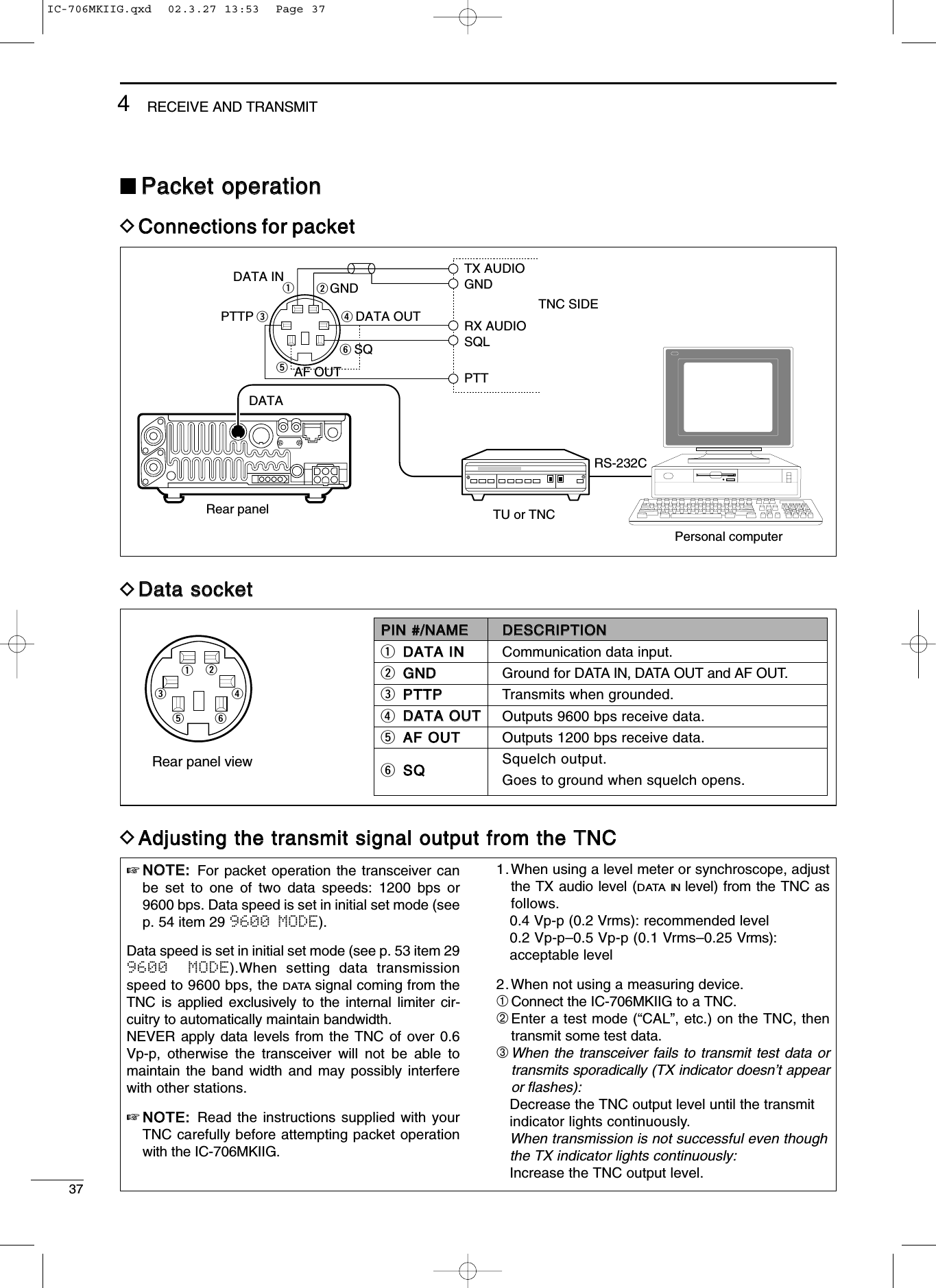
![384RECEIVE AND TRANSMITThe IC-706MKIIG can measure SWR in 2 ways:(A) Spot measurement; or (B) Plot measurement.((AA)) SSppoott mmeeaassuurreemmeenntt➀Confirm that the output power is over 30 W.➁Push [MENU] one or more times to select M3.➂Push [(F3)MET] to select the SWR meter.➃Push [MODE] one or more times to select CW orRTTY operation.•Key down or push [PTT] to transmit; then read the actu-al SWR from the meter:➠≤1.5 well matched antenna➠>1.5 check antenna or cable connection, etc.((BB)) PPlloott mmeeaassuurreemmeennttPlot measurement allows you to measure the SWRover an entire band.qConfirm that the output power is over 30 W.wPush [DISPLAY] twice to select G1 menu.ePush [MENU] to select G2.rSet the center frequency for the SWR to be mea-sured.tPush and hold [(F1)10k] one or more times toselect the desired frequency pitch.yPush and hold [(F2)] one or more times to selectthe desired step.uAfter selecting the desired pitch and step, push[(F3)STR] to measure the SWR.•RTTY mode is selected automatically.iPush and hold [PTT] to display the SWR in a bargraph readout.oWhen [PTT] is released, the frequency marker andfrequency indication move to the next frequencyto be measured.!0Repeat steps iand oto measure SWR over theentire frequency range.!1When the measured SWR is less than 1.5, theantenna is well matched.■SSWWRRThe IC-706MKIIG has a built-in circuit for measuringantenna SWR—no external equipment or specialadjustments are necessary.☞NNOOTTEE:: TThhee SSWWRR ccaann oonnllyy bbee mmeeaassuurreedd oonnAANNTT11,, HHFF//5500MMHHzz bbaannddss..DMMeeaassuurriinngg SSWWRRCHVFO ASWRS11 1.5 2 3537920 40 60dBCWBLANKSWR 1 1.5 2 3 5 10The best match is in this range.∞∞M3 FIL NB METG2 10k STRFrequency spanStep bar indicationFrequency indication markMeasure start indicatorSSppaannPush [F-1] for 1 sec. to change theselected span.SStteepp bbaarrPush [F-2] for 1 sec. to change thestep bar (3, 5, 7 or 9 steps are available.MMaarrkkeerrIndicates the currently active step bar.SSttaarrttFlashes while the SWR is being mea-sured. Step oThe antenna is well matched in this rangeCHVFO APOS15537920 401060dBBLANKG2 50k STR4.03.53.02.52.01.51.0RTTYIC-706MKIIG.qxd 02.3.27 13:53 Page 38](https://usermanual.wiki/ICOM-orporated/217700/User-Guide-317656-Page-41.png)
![395MMEEMMOORRYY AANNDD SSCCAANN OOPPEERRAATTIIOONN■MMeemmoorryy cchhaannnneellssThe transceiver has 105 memory channels (plus 2 callchannels). Memory mode is useful for quickly chang-ing to often-used frequencies.All 105 memory channels are tuneable which meansthe programmed frequency can be tuned temporarilywith the main dial, etc., in memory mode.➀Select M2 functions.•Push [DISPLAY] 1 or 2 times to select M.•Push [MENU] one or more times to select M2.➁Push [(F-3)V/M] to select memory mode.➂Rotate [M-CH] to select the desired memory chan-nel.•All memory channels including blank channels can beselected.•[UP]/[DN] on the microphone changes the frequency.➃To return to VFO mode, push [(F-3)V/M] again.Any unnecessary memory channels can be cleared.The cleared memory channels become blank chan-nels.➀Push [(F-3)V/M] in the M2 display to select memo-ry mode.➁Rotate [M-CH] to select a memory channel to becleared.➂Push [MCL(F-2)] for 2 sec. to clear the contents.•The programmed frequency and operating mode disap-pear and “}” appears.➃To return to VFO mode, push [(F-3)V/M] again.■MMeemmoorryy cchhaannnneell sseelleeccttiioonn■MMeemmoorryy cclleeaarriinnggNNoottee::During split frequency operation, programmedmemory contents can be called up to the SUB readout(dot matrix portion of the display).CWCHVFO A[EXAMPLE]: Selecting memory channel 17.V/MF-3USBCHMEMOSPLITCHMEMOUSBM-CH SHIFTMCLF-2SPLITPush for2 sec.CHMEMOUSBCHMEMOBLANKMMEEMMOORRYYCCHHAANNNNEELLMMEEMMOORRYYCCHHAANNNNEELLNNUUMMBBEERRCCAAPPAABBIILLIITTYYTTRRAANNSSFFEERRTTOO VVFFOOOOVVEERR--WWRRIITTIINNGGCCLLEEAARRRReegguullaarr((sspplliitt mmeemmoorryy))1–99Independent transmit and receivefrequencies and one mode in eachmemory channel.In addition, tone frequencies (or1750 Hz tone burst) can also bestored for repeater use.Ye s Ye s Ye sSSccaann eeddggeess1A–3B(3 pair)One frequency and one mode ineach memory channel as scanedges for programmed scan.Ye s Ye s NoCCaallll cchhaannnneell((sspplliitt mmeemmoorryy))C1 (144 MHz)C2 (430 MHz)Same as regular, but only 144/430MHz band can be programmed. Ye s Ye s NoIC-706MKIIG.qxd 02.3.27 13:53 Page 39](https://usermanual.wiki/ICOM-orporated/217700/User-Guide-317656-Page-42.png)
![405MEMORY AND SCAN OPERATION•PPrrooggrraammmmiinngg iinn VVFFOO mmooddee➀Select M2 functions.•Push [DISPLAY] 1 or 2 times to select M.•Push [MENU] one or more times to select the M2 func-tions.➁Set the desired frequency and operating mode inVFO mode.•If you want to program the split frequency function, pro-gram both receive and transmit frequencies into VFO Aand B, then turn ON the split function.•If you want to program a repeater function, set a tonefrequency (p. 49) in addition to the receive/transmit fre-quencies.➂Rotate [M-CH] to select the desired memory chan-nel, or the call channel (144/430 MHz bands only).•Select memory mode to confirm the contents, if desired.•“}” appears if the selected memory channel is ablank channel (and does not have contents).➃Push [(F-1)MW] for 2 sec. to program the displayedfrequency and operating mode into the memorychannel.To check the programmed contents, push [(F-3)V/M]to select memory mode; or, push [CALL] to selectthe call channel.■MMeemmoorryy//ccaallll pprrooggrraammmmiinnggCWCHVFO A[EXAMPLE]: Programming 7.088 MHz/LSB into ch 12.TSMODEMWF-1LSBBLANKSPLITCHVFO ALSBCHVFO ALSBCHVFO APush for2 sec.M-CH SHIFT•PPrrooggrraammmmiinngg iinn mmeemmoorryy mmooddee➀Set the desired frequency and operating mode.➁Select memory mode, then select the desiredmemory channel with [M-CH].•Push [Y]/[Z] when you want to program blank chan-nels.➂Push [(F-1)MW] for 2 sec. to program the displayedfrequency and operating mode into the memorychannel.CH[EXAMPLE]: Programming 21.280 MHz/USB intoch 18.TSMODEMWF-1SPLITPush for2 sec.CHMEMOUSBCHMEMOUSBCHMEMOCWCHMEMOUSBM-CH SHIFTIC-706MKIIG.qxd 02.3.27 13:53 Page 40](https://usermanual.wiki/ICOM-orporated/217700/User-Guide-317656-Page-43.png)
![415MEMORY AND SCAN OPERATION■FFrreeqquueennccyy ttrraannssffeerrrriinnggThe frequency and operating mode can be trans-ferred from memory mode to VFO mode.➀Select VFO mode with [(F-3)V/M] in the M2 dis-play.➁Select a memory channel with [M-CH].•Select memory mode to confirm the memory channel’scontents, if desired; then return to VFO mode.•“}” appears if the selected memory channel is ablank channel (and does not have contents). In thiscase transferring is not possible.➂Push [(F-2)MÜV] for 2 sec. to transfer the frequen-cy and operating mode.•Transferred frequency and operating mode appear inthe display.•“MÜV” does not appear in memory mode. MÜVF-2SPLITPush for2 sec.[EXAMPLE]: Transferring contents of memory 16.Operating frequency: 21.320 MHz/USB (VFO)Contents of memory 16: 14.020 MHz/CWCHVFO AUSBCHVFO AUSBCHVFO ACWM-CH SHIFT■MMeemmoorryy nnaammeessAll memory channels (including scan edges and thecall channel) can be tagged with alphanumeric namesof up to 9 characters each.All common keyboard characters (ASCII characters 33to 126) can be used, including numerals and punctua-tion marks.•CCaalllliinngg uupp mmeemmoorryy nnaammeess➀Select the G4 display.➥Push [DISPLAY] 1 or 2 times to select G.➥Push [MENU] one or more times to select theG4 display.➁Select a memory channel with [M-CH].•EEddiittiinngg ((pprrooggrraammmmiinngg)) mmeemmoorryy nnaammeess➀Call up the desired memory (channel) name asabove.➁Push [(F-3)É] to enter memory name edit mode.•“name edit” appears briefly, then a flashing cursorappears under the first character position.➂Rotate the main dial to select the desired charac-ter, then advance the cursor position.•[(F-3)Ç] increments the cursor position; [(F-1)Å] decre-ments the cursor position.•[(F-2)] overwrites the character with a space.➃Repeat this procedure until all desired charactershave been selected.➄Push [(MENU)Ä] to exit memory name edit mode.•The G4 display reappears and the programmed memo-ry name is displayed.G4 memory nameG4G4 Repeater ÉÄÅÖ name editÉF-3ÇF-3ÇF-3ÄMENUÄÅRÇÇÄÅRe ÇÄÅRepeaterÖÇÉIC-706MKIIG.qxd 02.3.27 13:53 Page 41](https://usermanual.wiki/ICOM-orporated/217700/User-Guide-317656-Page-44.png)
![425MEMORY AND SCAN OPERATION•CCaalllliinngg uupp aa ffrreeqquueennccyy ffrroomm aa mmeemmoo ppaaddYou can simply call up the desired frequency andoperating mode of a memo pad by pushing[(F-3)MPR] in the S1 display.•Make sure S1 is selected in advance.•Both VFO and memory modes can be use.•The frequency and operating mode are called up, startingfrom the most recently written.When you call up a frequency and an operatingmode from memo pads with [(F-3)MPR], the previous-ly displayed frequency and operating mode are auto-matically stored in a temporary pad. The frequencyand operating mode in the temporary pad can berecalled by pushing [(F-3)MPR] one or more times.NNoottee::If you change the frequency or operatingmode called up from a memo pad, the frequency andoperating mode in the temporary pad are erased.VFO orMEMORYmodeMEMO PADSMPRF-3MPRF-3USBUSBUSBUSBUSBUSBMP5MP4MP3MP2MP1■MMeemmoo ppaaddssThe transceiver has a memo pad function to store fre-quency and operating mode for easy write and recall.The memo pads are separate from memory channels.The default number of memo pads is 5, however, thiscan be increased to 10 in initial set mode if desired(p. 53).Memo pads are convenient when you want to memo-rize a frequency and operating mode temporarily,such as when you find a DX station in a pile-up or whena station is busy for a long time and you want to tem-porarily search for other stations.Use the transceiver’s memo pads instead of relying onhastily scribbled notes that are easily misplaced.•WWrriittiinngg ffrreeqquueenncciieess aanndd ooppeerraattiinngg mmooddeessiinnttoo mmeemmoo ppaaddss➀Select the S1 display.•Push [DISPLAY] 1 or 2 times to select S.•Push [MENU] one or more times to select S1.➁Push [(F-2)MPW] to program the frequency into amemo pad.When you write a 6th frequency and operatingmode, the oldest written frequency and operatingmode are automatically erased to make room for thenew settings.NNoottee::Each memo pad must have its own uniquecombination of frequency and operating mode;memo pads having identical settings cannot be writ-ten.Displayed frequency and modePushNewestMP5MP4MP3MP2MP1The oldest written frequencyand mode are erased.OldestMPWF-2USBUSBUSBUSBUSBUSBIC-706MKIIG.qxd 02.3.27 13:53 Page 42](https://usermanual.wiki/ICOM-orporated/217700/User-Guide-317656-Page-45.png)
![435MEMORY AND SCAN OPERATION■SSccaann ttyyppeess■PPrreeppaarraattiioonn•CChhaannnneellssFor programmed scan: Program scan edge frequen-cies into scan edge memory channels 1A and 1B(p. 34).For memory scan: Program 2 or more memory chan-nels except scan edge memory channels.For memory select scan: Designate 2 or more memorychannels as select memory channels—select a mem-ory channel, then push [(F-2)SEL] in the S2 display(memory mode) to designate the channel as a selectmemory channel.For priority watch: Program 1 memory channel to bewatched.•SSccaann rreessuummee OONN//OOFFFFYou can select the scan to resume or cancel whendetecting a signal, in initial set mode, item 21. Scanresume ON/OFF must be set before operating a scan.See p. 53 for ON/OFF setting and scan resume con-dition details.•SSccaann ssppeeeeddScan speed can be selected from 2 levels, high or low,in initial set mode. See p. 47 for details.•SSqquueellcchh ccoonnddiittiioonnPROGRAMMED SCANRepeatedly scans between two scan edge frequencies (scan edge memory channels 1A and 1B).This scan operates in VFO mode.SELECTED MEMORY SCANRepeatedly scans all selected memory channels.PRIORITY WATCHChecks for signals on a memory or call channel while operating on a VFO frequency.This scan operates in memory mode.This scan operates in memory mode.This scan operates in VFO mode.ScanScan edge 1A or 1B Scan edge 1B or 1AJumpMch 1 Mch 5Memory channel watch Call channel watchMemorychannelVFOfrequencyMch 2 Mch 3 Mch 4Mch 6Mch 7Mch 99MEMORY SCANRepeatedly scans all programmed memory channels.Mch 1 Mch 5Mch 2 Mch 3 Mch 4Mch 6Mch 7Mch 99BLANKS (select)S (select)S (select)S (select) S (select)S (select)S (select)S (select)S (select) S (select)BLANKCallchannelVFOfrequencySSCCAANNSSTTAARRTTSSWWIITTHHPPRROOGGRRAAMMMMEEDDSSCCAANNMMEEMMOORRYY SSCCAANNSSPPRRIIOORRIITTYYWWAATTCCHHSSQQUUEELLCCHHOOPPEENNThe scan continuesuntil it is stoppedmanually, and doesnot pause even if itdetects signals.This is not applicablewhen the scanresume is OFF and aprogrammable step(more than 1 kHz) isselected.Scan pauses on eachchannel when thescan resume is ON;not applicable whenOFF.SSQQUUEELLCCHHCCLLOOSSEEDDScan stops when detecting a signal.If you set scan resume ON in initial set mode,the scan pauses for 10 sec. when detecting asignal, then resumes. When a signal disap-pears while scan is paused, scan resumes 2sec. later.IC-706MKIIG.qxd 02.3.27 13:53 Page 43](https://usermanual.wiki/ICOM-orporated/217700/User-Guide-317656-Page-46.png)
![445MEMORY AND SCAN OPERATION➀Select VFO mode, then set a frequency.➁Close the squelch with [SQL].➂Set the desired memory channel as the watchingchannel.➃Select S2, then push [(F-2)PRI] to start the watch.•Decimal point blinks while scanning.➄When the scan detects a signal, the scan pausesfor 10 sec. or until the signal disappears, depend-ing on the resume setting.➅To cancel the scan push [(F-2)PRI]. NNoottee::The paused condition when detecting a signaldiffers depending on the scan resume condition.resume on: pauses for 10 sec.resume off: pauses until the signal disappears.➀Select memory mode.➁Close the squelch with [SQL].➂Select S2, then push [(F-1)SCN] to start the mem-ory scan.•Decimal point blinks while scanning.➃Push [(F-2)SEL] to change the memory scan toselect memory scan.•Push [(F-2)SEL] for 2 sec. to clear all select memorychannels.➄When the scan detects a signal, the scan stops orpauses depending on the resume setting.➅To cancel the scan push [(F-1)SCN].NNoottee::Two or more memory channels must be desig-nated as select memory channels for select memoryscan to start.S2 SCN SEL V/MSelectmemory modeDesignate“S.”F-1 F-2Push [(F-1)SCN], then [(F-2)SEL].CHSMEMOPOS15537920401060dBUSB➀Select memory mode.➁Close the squelch with [SQL].➂Select S2, then push [(F-1)SCN] to start the scan.•Decimal point blinks while scanning.➃When the scan detects a signal, the scan stops orpauses depending on the resume setting.➄To cancel the scan push [(F-1)SCN].NNoottee::Two or more memory channels must be pro-grammed for memory scan to start.S2 SCN SEL V/MSelectmemory modeF-1 then push [(F-1)SCN]CHMEMOPOS15537920401060dBUSB➀Select VFO mode.➁Select the desired operating mode.•The operating mode can also be changed while scan-ning.➂Set [SQL] open or closed.•See page a left for squelch condition.➃Select S2, then push [(F-1)SCN] to start the scan.•Decimal point blinks while scanning.➄When the scan detects a signal, the scan turnsOFF, pauses or ignores it depending on theresume setting and the squelch condition.•During scan [TS] can be used only when resume is ON.➅To cancel the scan push [(F-1)SCN].NNoottee::If the same frequencies are programmed intothe scan edge memory channels 1A and 1B, pro-grammed scan does not start.■PPrrooggrraammmmeedd ssccaann ooppeerraattiioonn■MMeemmoorryy ssccaann ooppeerraattiioonn■SSeelleecctt mmeemmoorryy ssccaann ooppeerraattiioonnS2 SCN PRI V/MSelectVFO modeSelect watchingchannelF-2 Push [(F-2)PRI].CHPOS15537920401060dBUSBVFO A■PPrriioorriittyy wwaattcchhCHVFO APOS15537920401060dBUSBS2 SCN PRI V/MSelectVFO modeF-1 then push [(F-1)SCN]IC-706MKIIG.qxd 02.3.27 13:53 Page 44](https://usermanual.wiki/ICOM-orporated/217700/User-Guide-317656-Page-47.png)
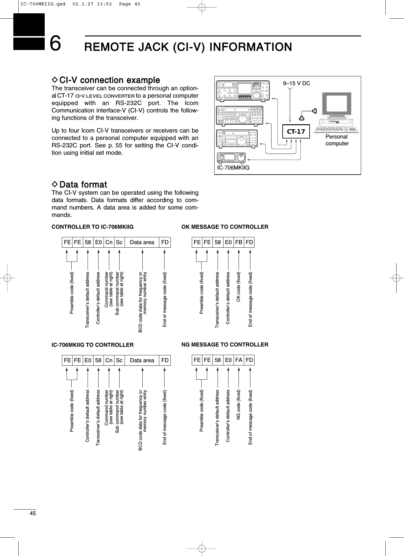
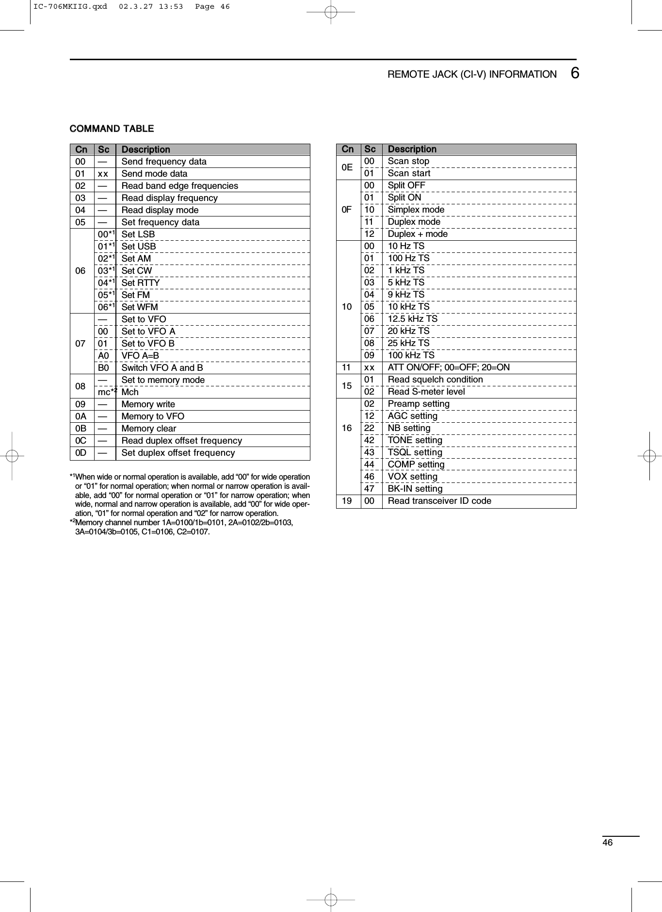
![477SSEETT MMOODDEE■GGeenneerraallSet mode is used for programming infrequentlychanged values or conditions of functions. The IC-706MKIIG has 2 separate set modes: quick set modeand initial set mode.DQQuuiicckk sseett mmooddee ooppeerraattiioonn➀While power is ON, push [DISPLAY] for 2 sec.•Quick set mode is selected and one of its items appears.•Quick set mode items vary depending on the operatingmode (SSB, FM, etc.) selected.➁Push [MENU] one or more times to select thedesired item.•[M-CH] or [Y]/[Z] can also be used.➂Rotate the main dial to set the values or conditionsfor the selected item.➃Repeat steps ➁and ➂to set other items.➄To exit quick set mode, push [DISPLAY] momentar-ily.DIInniittiiaall sseett mmooddee ooppeerraattiioonn➀Push [POWER] for 2 sec. to turn power OFF.➁While pushing [LOCK] push [POWER] to turnpower ON.•Initial set mode is selected and one of its items appears.➂Push [MENU] one or more times to select thedesired item.•[M-CH] or [Y]/[Z] can also be used.➃Rotate the main dial to set the values or conditionsfor the selected item.➄Repeat steps ➂and ➃to set other items.➅To exit initial set mode, push [POWER] for 2 sec. toturn power OFF.➆Push [POWER] to turn power ON again.•The conditions selected in initial set mode are now effec-tive.[POWER][MENU] [LOCK]Main dialItem numberItemValue or condition 1 MODE SELECT[DISPLAY EXAMPLE: INITIAL SET MODE][M-CH][Y][Z]Q1 RF POWERUSB[POWER][MENU][M-CH][DISPLAY]Main dial[Y][Z]Item numberItemValue or condition[DISPLAY EXAMPLE: QUICK SET MODE]POS15537920401060dBIC-706MKIIG.qxd 02.3.27 13:53 Page 47](https://usermanual.wiki/ICOM-orporated/217700/User-Guide-317656-Page-50.png)
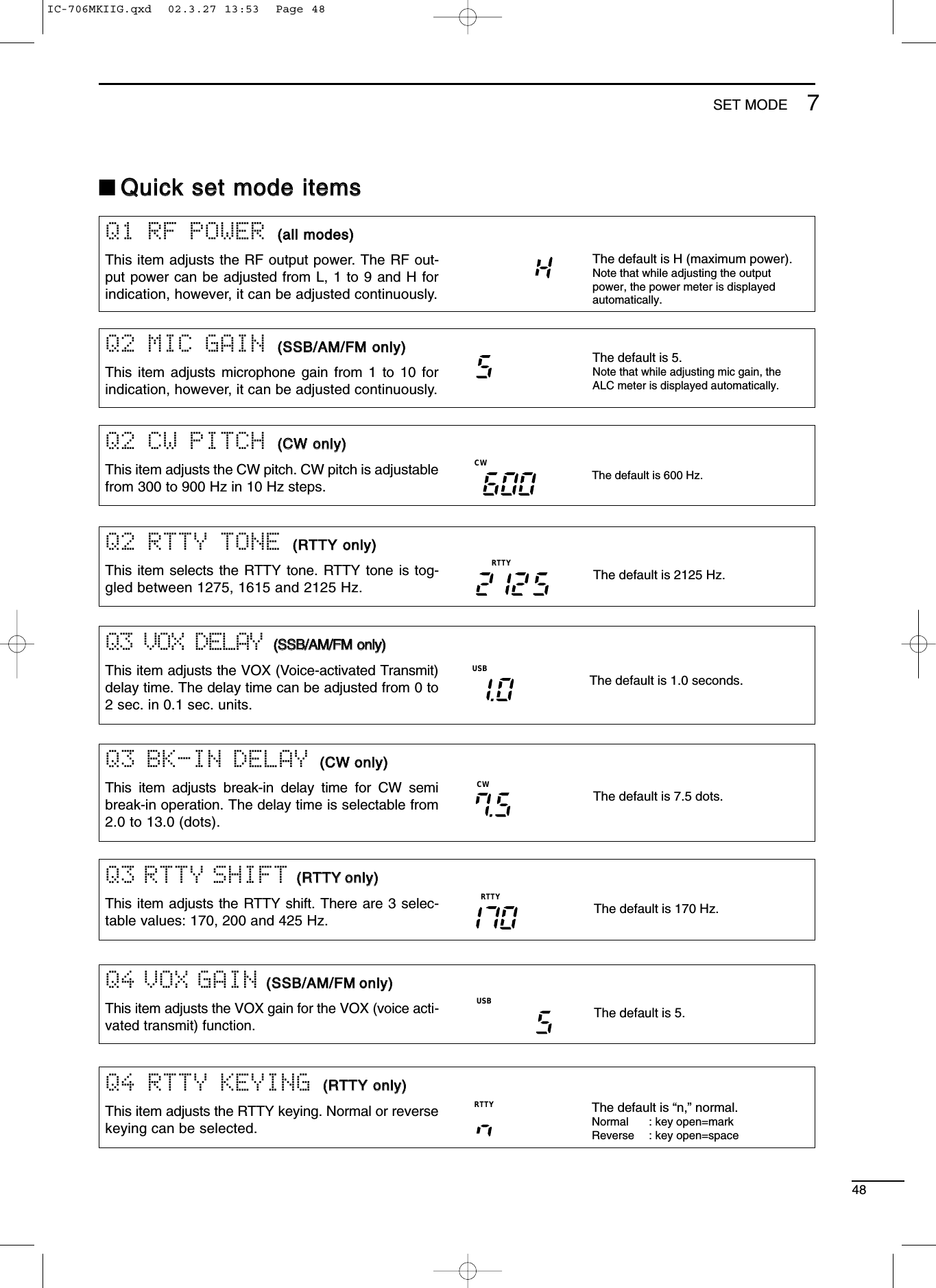
![497SET MODEQ6 CARRIER Frq ((SSSSBB oonnllyy))This item adjusts the carrier frequency (BFO frequen-cy), allowing you to change the audio characteristics.Selectable values are –200 to +200 Hz in 10 Hz steps.USBThe default is 0 Hz.Q6 RPTR TONE ((FFMM oonnllyy))This item selects a subaudible tone for FM-T modeoperation to access a repeater. There are 50 tonesavailable from 67.0 Hz to 254.1 Hz (see table at right). •Available subaudible tones Unit: HzThe default is 88.5 Hz.FMQ4 CW PADDLE ((CCWW oonnllyy))This item adjusts the CW paddle type. Four selec-tions are available.•n : normal (for electronic keyer use)•r : reverse (for electronic keyer use)•buG : When using the electronic key, key downproduces a “dash,” releasing the keyautomatically produces a “dot(s).”•oFF : Turns OFF the electronic keyer (forstraight key use)•ud : For using the microphone’s [UP]/[DN]keys instead of the CW paddle.The default is “n,” normal.CWQ5 KEY SPEED ((CCWW oonnllyy))This item adjusts the CW key speed. The key speedcan be selected from 6 to 60 wpm. The default is 20 wpm.CWQ6 RATIO ((CCWW oonnllyy))This item adjusts the CW key ratio (or weight). Theratio can be selected from 2.8 to 4.5. The default is 3.0.CWQ7 TONE SQL ((FFMM oonnllyy))This item adjusts sets a subaudible tone for tonesquelch use. (the same subaudible tone frequenciesas for repeater operation are available—see above).The default is 88.5 Hz.FM67.0 79.9 94.8 110.9 131.8 156.7 171.3 186.2 203.5 229.169.3 82.5 97.4 114.8 136.5 159.8 173.8 189.9 206.5 233.671.9 85.4 100.0 118.8 141.3 162.2 177.3 192.8 210.7 241.874.4 88.5 103.5 123.0 146.2 165.5 179.9 196.6 218.1 250.377.0 91.5 107.2 127.3 151.4 167.9 183.5 199.5 225.7 254.1Q5 ANTI VOX ((SSSSBB//AAMM//FFMM oonnllyy))This item adjusts the ANTI-VOX gain for the VOX(voice activated transmit) function.USBThe default is 5.IC-706MKIIG.qxd 02.3.27 13:53 Page 49](https://usermanual.wiki/ICOM-orporated/217700/User-Guide-317656-Page-52.png)
![507SET MODE4 BACK LIGHT((ddiissppllaayy bbaacckklliigghhttiinngg))The function display backlighting can be set to high,low or OFF to suit ambient lighting. Display backlighting set tohigh (default).Display backlighting set tolow.5 KEY LIGHT((kkeeyy//sswwiittcchh bbaacckklliigghhttiinngg))The key/switch backlighting can be set to high, low orOFF to suit ambient lighting. Display backlighting set tohigh (default).Display backlighting set tolow.■IInniittiiaall sseett mmooddee iitteemmss2 BEEP ((ccoonnffiirrmmaattiioonn bbeeeepp))A beep sounds each time a switch is pushed to con-firm it. This function can be turned OFF for silentoperation.3 BAND BEEP ((bbaanndd bbeeeepp))A beep sounds when an operating frequency enters orexits a transmit frequency range. This functions inde-pendent of the confirmation beep setting (above).Confirmation beep ON(default)Confirmation beep OFFBand beep ON(default)Band beep OFF1 MODE SELECT ((aallll mmooddeess))This item is available in all modes, and allows you tosimplify operation by inhibiting the selection ofunneeded operating modes during normal opera-tion. For example if you are operating mobile and onlyplan on using FM and AM modes, use “MODESELECT” to inhibit access to all other modes (SSB,CW, RTTY, WFM), thereby making selection of AM orFM quick and easy.The default is on for all operatingmodes. To toggle an operating modeon or off, push (or push and hold)[MODE] one or more times until thedesired mode is displayed, then rotatethe main dial to set on or off.Q8 RPTR-T SCN((rreeppeeaatteerr ttoonnee ssccaann))During repeater operation, you can detect the tonefrequency necessary to open a repeater (see p. 30).The default is 88.5 Hz.FMQ8 T-SQL SCN((ttoonnee ssqquueellcchh ttoonnee ssccaann))During tone squelch operation, you can detect thetone frequency necessary to communicate usingtone squelch (see p. 31).The default is 88.5 Hz.FMIC-706MKIIG.qxd 02.3.27 13:53 Page 50](https://usermanual.wiki/ICOM-orporated/217700/User-Guide-317656-Page-53.png)
![51SET MODE711 PEAK HOLD ((ppeeaakk hhoolldd))When the peak hold function is ON, the highest acti-vated segment of the meter remains visible for 0.5sec.; when OFF, the meter functions normally. Peak hold ON(default)Peak hold OFF6 AUTO OFF ((aauuttoo ppoowweerr OOFFFF))The auto power OFF function can be used to auto-matically turn the transceiver OFF after a specifiedtime of operation. This item can be set to 30 min., 60min., 90 min., 120 min., or OFF.Auto power OFF set to20 min.Auto power OFFdeactivates. (default)7 RF/SQL ((SSQQLL//AAUUTTOO//RRFF•SSQQLL))The [RF/SQL] control can be set as the squelch con-trol (default), the RF/squelch control (USA versiondefault) or automatic (acts as squelch in FM/WFM/AMmodes; as RF in SSB/CW/RTTY modes). (See p. 22)NNoottee::RF gain does not function in WFM modeThe [RF/SQL] controlfunctions as RF gaincontrol only.The [RF/SQL] controlfunctions as squelchcontrol only.8 SUBDIAL ((SSuubbddiiaall ffuunnccttiioonn))When this item is set to “rit,” pushing [RIT/SUB]turns the RIT function ON (lights red)—rotating [M-CH] changes the RIT frequency; when this item is setto “Freq,” pushing [RIT/SUB] turns the sub dial func-tion ON (lights green)—rotating [M-CH] changes theoperating frequency. Note that in FM, WFM and AMmodes, pushing [RIT/SUB] always selects the subdial function (lights green), regardless of this setting.Pushing [RIT/SUB]selects the RIT function(default).Pushing [RIT/SUB]selects the sub dial function.9 OPT. FIL 1 ((ooppttiioonnaall ffiilltteerr))When an optional filter is installed, this selection isnecessary, otherwise the filters cannot be selected.Selections available are FL-100, FL-101, FL-103,FL-223, FL-232 and none (default). See p. 22 forusable filters for each mode and see p. 60 for filterinstallation.10 OPT. FIL 2 ((ooppttiioonnaall ffiilltteerr))When an optional filter is installed, this selection isnecessary, otherwise the filters cannot be selected.Selections available are FL-100, FL-101, FL-103,FL-223, FL-232 and none (default). See p. 22 forusable filters for each mode and see p. 60 for filterinstallation.No filters are selected(default).FL-223 (for LSB/USB mode)is selected.No filters are selected(default).FL-223 (for LSB/USB mode)is selected.IC-706MKIIG.qxd 02.3.27 13:53 Page 51](https://usermanual.wiki/ICOM-orporated/217700/User-Guide-317656-Page-54.png)
![5215 DUP HF ((dduupplleexx ooffffsseett))This item sets the offset for the duplex functionwhen operating on the HF bands.Default is 0.100 MHz.16 DUP 50M ((dduupplleexx ooffffsseett))This item sets the offset for the duplex functionwhen operating on the 50 MHz band. Default is 0.500 MHz.17 DUP 144M ((dduupplleexx ooffffsseett))This item sets the offset for the duplex functionwhen operating on the 144 MHz band. Default is 0.600 MHz.18 DUP 430M ((dduupplleexx ooffffsseett))This item sets the offset for the duplex functionwhen operating on the 430 MHz band. Default is 5.000 MHz.19 1TOUCH RPTR((oonnee ttoouucchh rreeppeeaatteerr))This item sets the offset direction when using theone-touch repeater function. +duplex or –duplexcan be selected. Duplex direction is setto –duplex.Duplex direction is set to+duplex.DUP DUP14 SPL OFFSET ((sspplliitt ooffffsseett))This item sets the offset (difference between transmitand receive frequencies) for the quick split function.Note that this setting is not valid in FM/WFM modes.Default is 0.100 MHz.13 SPLIT LOCK ((sspplliitt lloocckk))When this item is ON the main dial can be used toadjust the transmit frequency (XFC) even while thelock function is activated. Split lock function OFF(default)Split lock function ON12 QUICK SPLIT((qquuiicckk sspplliitt ffuunnccttiioonn))When this item is set to ON, pushing [SPL] for 2 sec.sets the undisplayed VFO frequency to the dis-played VFO frequency plus the split offset or duplexoffset, and activates split operation.Quick split function ON(default).Quick split function OFF.7SET MODEIC-706MKIIG.qxd 02.3.27 13:53 Page 52](https://usermanual.wiki/ICOM-orporated/217700/User-Guide-317656-Page-55.png)
![53SET MODE726 PWR ON CHK ((PPoowweerr oonn cchheecckk))When this item is set to “on,” the set output power isbriefly displayed when turning power ON (RIT andauto power off settings are also displayed if activat-ed); when turned “oFF,” the display goes directly tofrequency indication at power ON.Power on check ON (default)Power on check OFF24 AM NB ((NNooiissee bbllaannkkeerr iinn AAMM mmooddee))When this item is set to ON, the noise blanker func-tion is available in AM mode. This is useful when com-municating in AM mode (the noise blanker functionshould not be used when listening to regular AMbroadcasts as it may degrade the received audio).Noise blanker available(default)Noise blanker not available20 AUTO RPTR ((aauuttoo rreeppeeaatteerr))When this item is set to “on 1”, the tone encoder isnot set when the auto repeater is activated; when setto “on 2” the auto repeater function also sets thetone encoder on.Auto repeater function OFF(default).Auto repeater function ON,tone encoder OFF.22 SCAN SPEED ((ssccaann ssppeeeedd))This item sets the rate at which channels or frequen-cies are scanned during scan operations. High or lowcan be selected.23 U/D SPEED ((uupp//ddoowwnn ssppeeeedd))This item sets the rate at which frequencies arescanned through when the [UP]/[DN] switches arepushed and held. High or low can be selected.Scan speed is set to high(default).Scan speed is set to low.Up/down speed is set tohigh (default).Up/down speed is set to low.21 SCAN RESUME ((ssccaann rreessuummee))This item sets the scan resume function ON or OFF.ON: scan resumes 10 sec. after stopping on a signal(or 2 sec. after a signal disappears); OFF: scan doesnot resume after stopping on a signal. For the prioritywatch, setting to OFF pauses the watch until signaldisappears and scan resumes.Scan resume function isturned ON (default).Scan resume function isturned OFF.25 PAD CH ((aavvaaiillaabbllee mmeemmoo ppaaddss))This item sets the number of memo pad channelsavailable. 5 or 10 memo pads can be set. 5 memo pads are available(default).10 memo pads are available.IC-706MKIIG.qxd 02.3.27 13:53 Page 53](https://usermanual.wiki/ICOM-orporated/217700/User-Guide-317656-Page-56.png)
![5429 9600 MODE((DDaattaa ssoocckkeett ssppeeeedd))This is used to change the communications speedpacket operation. The data socket can be set to1200 or 9600 baud. Default is 9600 baud.30 VSEND SEL((AACCCC ssoocckkeett oouuttppuutt))“on”: VSEND is for 144/430 MHz; HSEND is forthe HF/50 MHz“U only”: VSEND is for 430 MHz; HSEND is forHF/50/144 MHz“oFF”: VSEND is not used; HSEND is for all bands.The default is VSEND is for the 144/430 MHz band;HSEND is for the HF/50 MHz band.31 SPEECH LANGWhen the optional UT-102 VOICE SYNTHESIZER UNITisinstalled, you can select between English andJapanese as the language.32 SPEECH SPDWhen the optional UT-102 VOICE SYNTHESIZER UNITisinstalled, you can select between faster or slowersynthesizer output.Voice synthesizer functionsin English (default).Voice synthesizer functionsin Japanese.Voice synthesizer outputis faster (default).Voice synthesizer outputis slower.((vvooiiccee ssyynntthheessiizzeerr llaanngguuaaggee))((vvooiiccee ssyynntthheessiizzeerr ssppeeeedd))28 PTT TUNE ((PPTTTT ttuunnee ffuunnccttiioonn))When an optional AH-4 ANTENNA TUNERis connect-ed, tuning can be started automatically at themoment the PTT is pushed.27 A-TUNE STRT((aauuttoo ttuunneerr ssttaarrtt))The optional AT-180 ANTENNA TUNERhas an automat-ic start capability which starts tuning if the SWR ishigher than 1.5–3.When “oFF” is selected, the tuner remains OFFeven when the SWR is poor (1.5–3).When “on” is selected, automatic tune starts evenwhen the tuner is turned OFF.NNoottee::Even when “on” is selected, automatic tunedoes not start for the 50 MHz band.Auto tune function OFF(default).Auto tune function ON.Tuning starts when pushing [PTT] on a new frequency.Tuning starts only when[TUNER] is pushed (default).7SET MODEIC-706MKIIG.qxd 02.3.27 13:53 Page 54](https://usermanual.wiki/ICOM-orporated/217700/User-Guide-317656-Page-57.png)
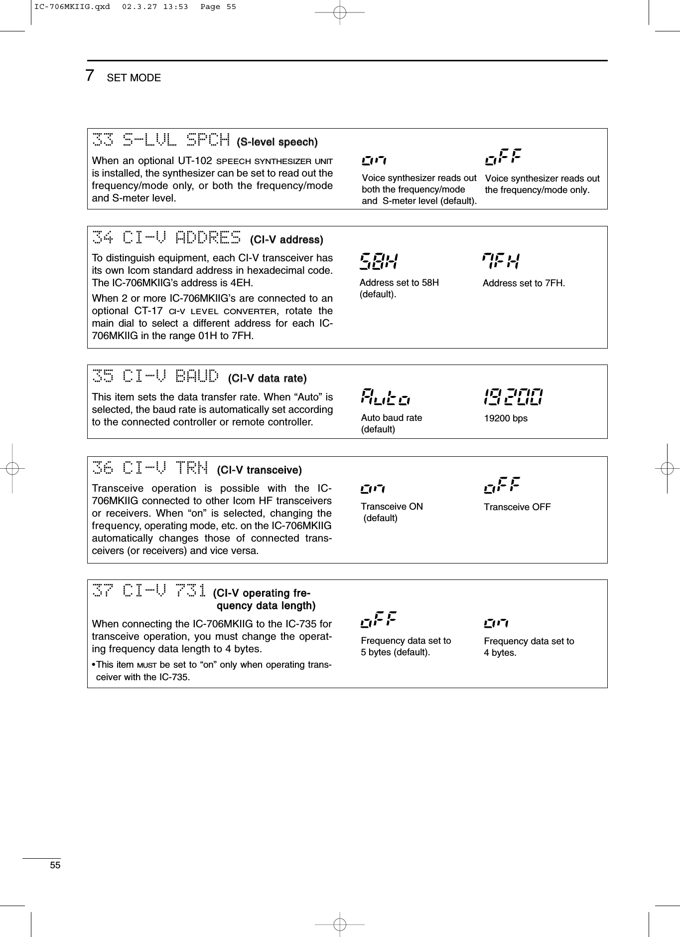
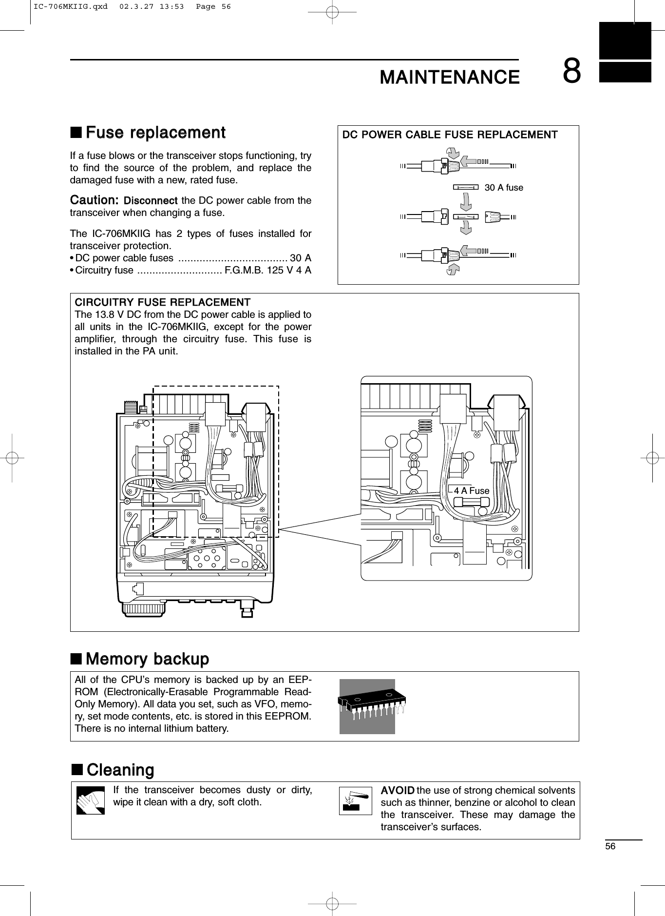
![579TTRROOUUBBLLEESSHHOOOOTTIINNGGThe following chart is designed to help you correctproblems which are not equipment malfunctions.If you are unable to locate the cause of a problem orsolve it through the use of this chart, contact yournearest Icom Dealer or Service Center.PROBLEMPOWER SUPPLYRECEIVEPOSSIBLE CAUSE SOLUTION REF.Power does not come on when the [POWER] switch is pushed. No sound comes from the speaker.Sensitivity is low.Receive audio is distor-ted.Receive signal is distor-ted with strong signals.DC power cable is improperly connected.Fuse is blown.Battery is exhausted if you are using a 12 V battery as the power source.Reconnect the power cable correctly.Check for the cause, then replace the fuse with a spare one.(Fuses are installed in two places. One is installed in the DC power cable and the other is installed in the PA unit.Check the battery voltage with the [POWER] pushed IN.p. 13p. 56—p. 1p. 1—p. 12p. 12——p. 14pgs. 27, 28p. 21p. 19p. 20p. 21p. 21Volume level is set too low.The squelch is closed.The transceiver is in the transmitting condition.An external speaker or headphones are connected.The antenna is not connected properly.The antenna feed line is cut or shorted.The antenna for another band is selected.The antenna is not properly tuned.The attenuator function is activated.The operating mode is not selected correctly.The [SHIFT] control is set off-center.Noise blanker function is activated.Preamp is activated.Rotate [AF] clockwise to obtain a suit-able listening level.Rotate [SQL] counterclockwise to open the squelch.Release [PTT] on the microphone or check the SEND line of an external unit, if connected.Check the external speaker or head-phone plug connection.Check the speaker ON/OFF switch or speaker A/B switch, when an optional SP-20 EXTERNAL SPEAKER is in use.Reconnect to the antenna connector.Check the feed line and correct any improper conditions.Select an antenna suitable for the operating frequency.Make sure that [ANT1] is used for frequencies less than 60 MHz and [ANT2] is used for frequencies of 60 MHz and above.Push [TUNE] to manually tune the antenna.Push [ATT] to turn the function OFF.Select a suitable operating mode.Set [SHIFT] to the center position.Push [NB] to turn the function OFF.Push [P.AMP] to turn the function OFF.IC-706MKIIG.qxd 02.3.27 13:53 Page 57](https://usermanual.wiki/ICOM-orporated/217700/User-Guide-317656-Page-60.png)
![589TROUBLESHOOTINGPROBLEMTRANSMITDISPLAYSCANPOSSIBLE CAUSE SOLUTION REF.Transmitting is impossi-ble. Output power is too low. No contact possible with other stations. Repeater cannot be ac-cessed. Transmitted signals are distorted. Displayed frequency does not change proper-ly.Programmed scan does not stop.Programmed scan does not start.Memory scan does not start.Memory select scan does not start.The operating frequency is not set to a ham band. Power is set to a lower power than maximum.Microphone gain is set too low.The antenna is not connected properly.The antenna feed line is cut or shorted.An antenna for another band is selec-ted.The antenna is not properly tuned.RIT function is activated.Split function is activated.Split function is not activated.An incorrect transmit frequency is set.Subaudible tone encoder is OFF and repeater requires a tone for access.Programmed subaudible tone fre-quency is wrong.Microphone gain is set too high.[COMP LEVEL] is rotated too far clockwise with the speech compres-sor ON.The dial lock function is activated.The internal CPU has malfunctioned.Squelch is open.The same frequencies have been programmed in scan edge memory channels.2 or more memory channels have not been programmed.2 or more memory channels have not been designated as select channels.Set squelch to the threshold position.Programm different frequencies into scan edge memory channels.Program 2 or more memory chan-nels.Designate 2 or more memory chan-nels as select channels for the scan.Set gain in quick set mode.Set [COMP LEVEL] to a suitable pos-ition.Push [LOCK] to deactivate the func-tion. Reset the CPU.(While pushing [UP] and [DN] push [POW-ER] to turn power ON.Push [DUP] to turn the function ON.Set the proper frequencies into VFO A and B or into one of the memory channels.Use [TON] to select FM-T.Program the required frequency using quick set mode.Push RIT to turn the function OFF.Push [SPLIT] to turn the function OFF.Set the output power in quick set mode.Set microphone gain to a suitable position using quick set mode.Reconnect the antenna connector.Check the feed line and correct any improper conditions.Select an antenna suitable for the op-erating frequency.Push [TUNE] to manually tune the antenna when an optional antennal tuner is connected.Set the frequency to a ham band. p. 17p. 44p. 44——p. 14pgs. 27, 28p. 20p. 29p. 29p. 17p. 30p. 49p. 48p. 5p. 2p. 15p. 23p. 44p. 41p. 44IC-706MKIIG.qxd 02.3.27 13:53 Page 58](https://usermanual.wiki/ICOM-orporated/217700/User-Guide-317656-Page-61.png)
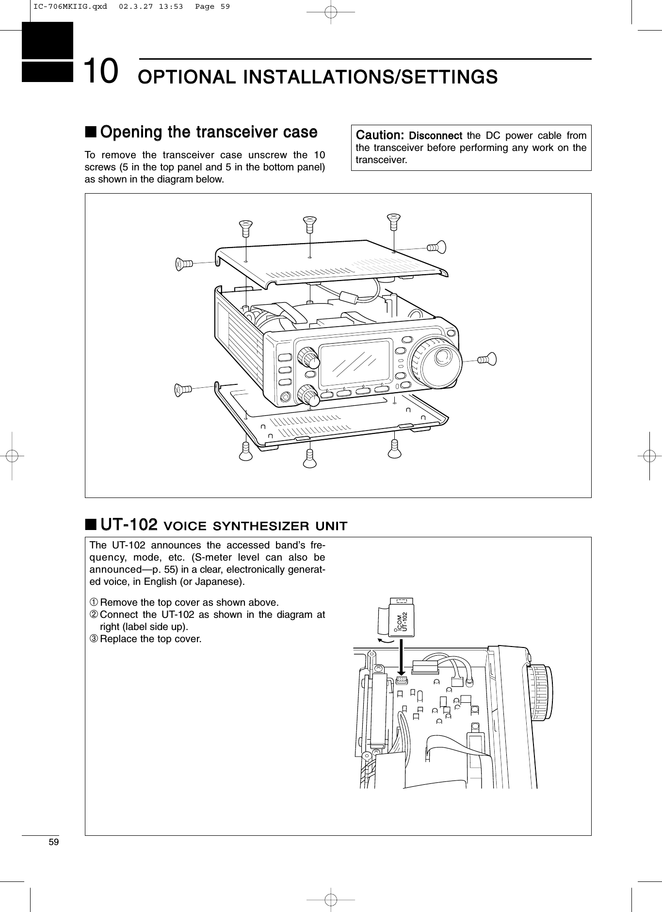
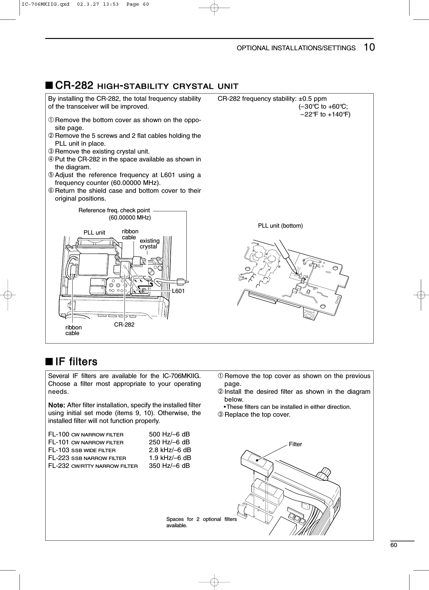
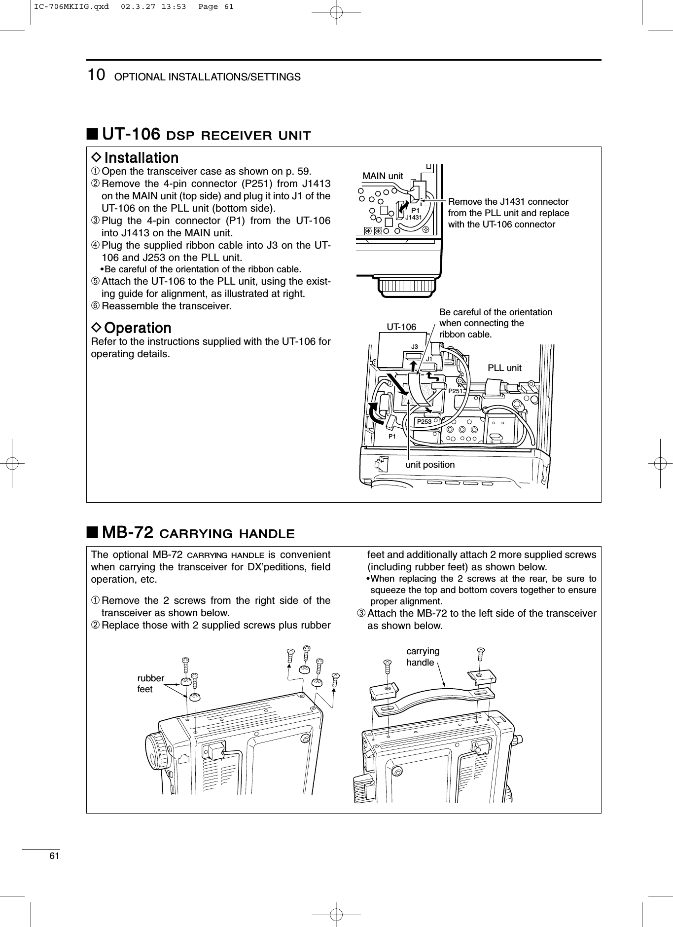
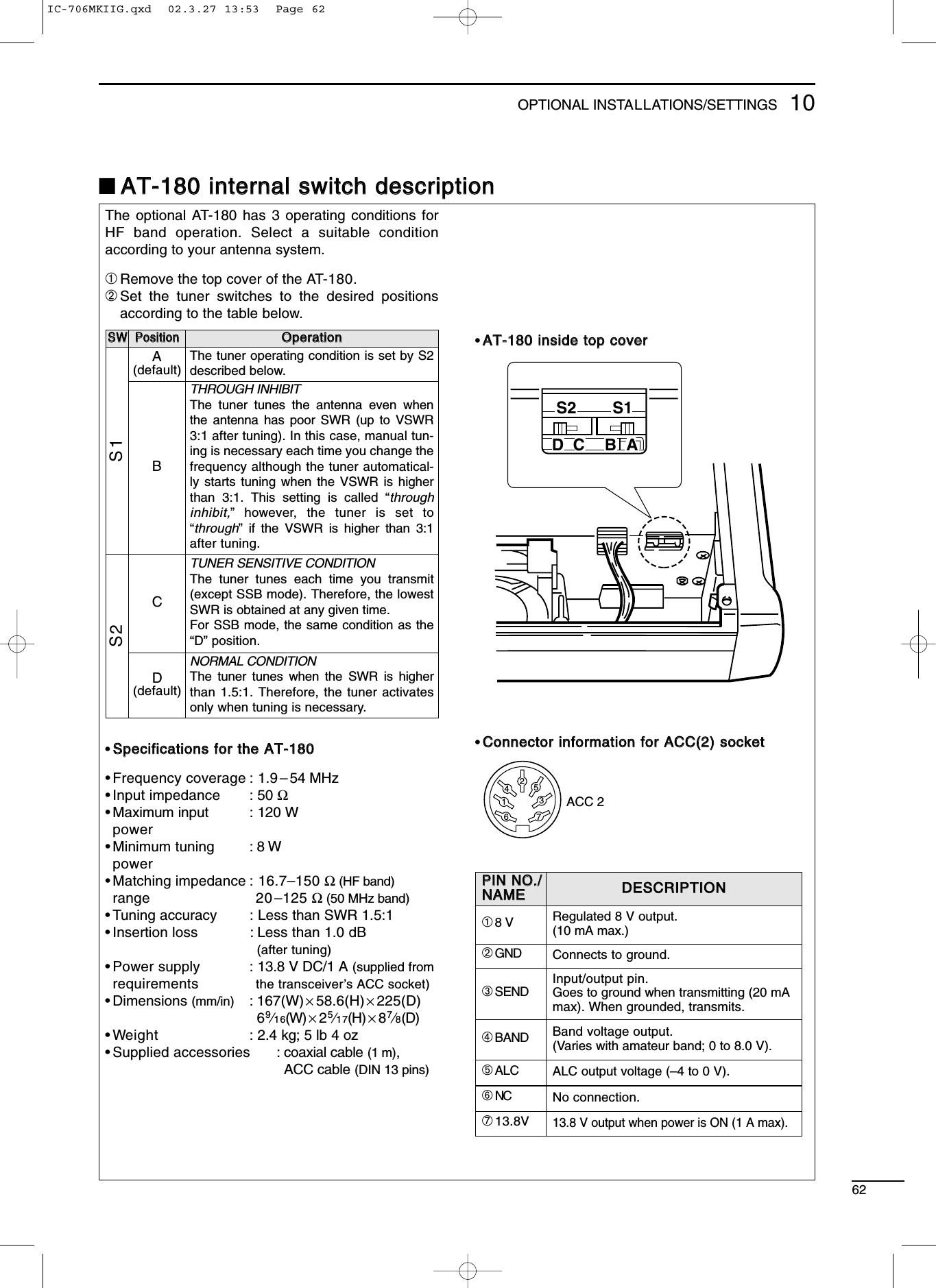
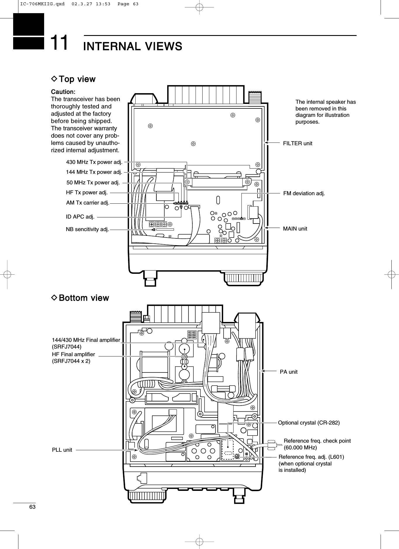
![6412OOPPTTIIOONNSSIICC--PPWW11HF + 50 MHz 1 kW LINEAR AMPLIFIERFull-duty 1 kW linear amplifierincluding an automatic antennatuner. Has automatic tuning andband selection capability. Fullbreak-in (QSK) operation is possi-ble. The amplifier/power supplyunit and the remote control unit areseparated. The OPC-599 is nec-essary to connect the IC-706MKIIG to the IC-PW1.AATT--118800HF/50 MHz AUTOMATICANTENNA TUNERFully automatic antenna tuner with presetmemories for each 100 kHz. Unique “auto-matic tuner on” function is available. See p. 62for AT-180 specifications.HHMM--111188TTHAND MICROPHONE Includes DTMF keypad, hand microphone.SSMM--2200DESKTOP MICROPHONEIncludes [UP]/[DOWN] switches and a lowcut function. The OPC-589 is necessary touse this microphone.MMBB--6655MOUNTING BASEAllows you to conveniently vehicle-mount thefront panel of the IC-706MKIIG. An MB-63must be used in combination with the MB-65.AAHH--22bbANTENNA ELEMENTA 2.5 m long antennaelement for mobileoperation with the AH-3.•Frequency coverage3.5–28 MHz bandwith the AH-3SSMM--88DESKTOP MICROPHONEIncluding 2 connection cables for simultane-ous connection of 2 transceivers. Has[UP]/[DOWN] switches. The OPC-589 isnecessary to use this microphone.MMBB--6633MOUNTING BRACKETMetal plate for attaching the front panel to awall or other such flat surface.AAHH--44HF AUTOMATIC ANTENNATUNERSpecially designed to tune a long wire anten-na for portable or mobile HF/50 MHz opera-tion. The “PTT tune” function provides simpleoperation.•Input power rating: 150 WPPSS--8855DC POWER SUPPLYLight weight switching regulator systempower supply.•Output voltage: 13.8 V DC•Max. current drain: 20 AMMBB--6622MOBILE MOUNTING BRACK-ETMounts the transceiver main body, with orwithout the front panel, inside a vehicle.IC-706MKIIG.qxd 02.3.27 13:53 Page 64](https://usermanual.wiki/ICOM-orporated/217700/User-Guide-317656-Page-67.png)
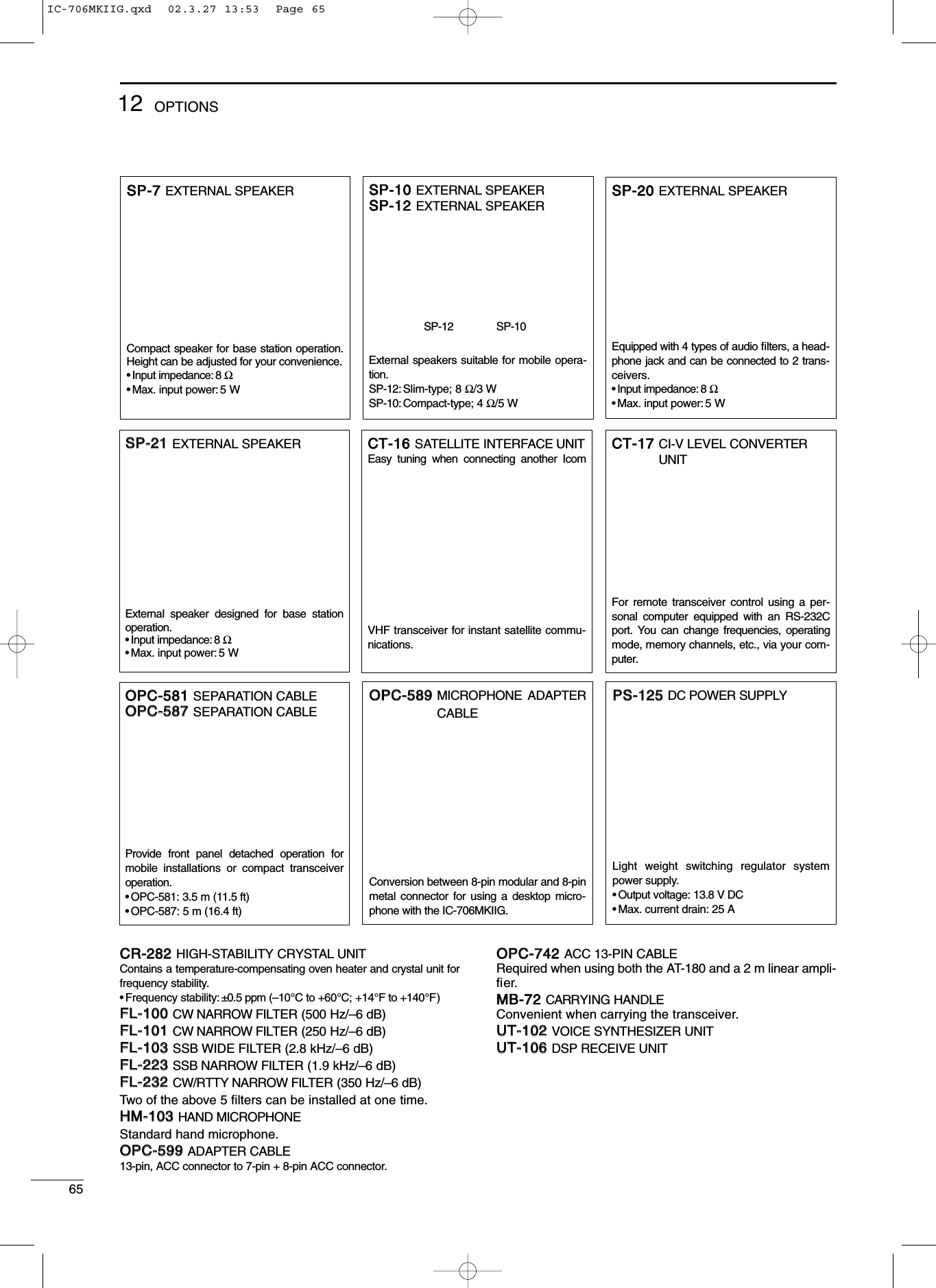
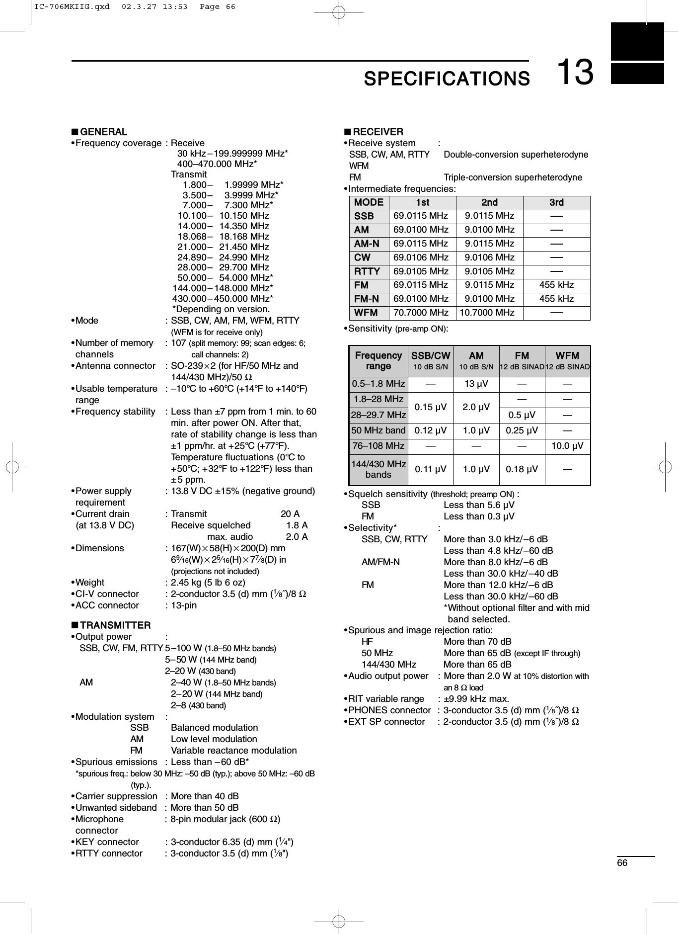
![6714 MMEENNUU GGUUIIDDEEInitial set modeNo. Indication Description1 MODE SELECT2 BEEP3 BAND BEEP4 BACK LIGHT5 KEY LIGHT6 AUTO OFF7 RF/SQL8 SUB DIAL9 OPT.FIL 110 OPT.FIL 211 PEAK HOLD12 QUICK SPLITMode availabilityConfirmation beepsBand edge beepsDisplay backlightingKey backlightingAuto power OFF functionRF gain/squelch controlSub dial RIT functionSpeech synthesizer lang.Speech synthesizer speedSpeech synthesizer S-meterMeter peak function[UP]/[DN] speedAuto tune start functionNo. Indication Description13 SPLIT LOCKPTT tune function14 SPL OFFSET15 DUP HF16 DUP 50M17 DUP 144M18 DUP 430M19 1TOUCH RPTRNo. of memory pads20 AUTO RPTR21 SCAN RESUME22 SCAN SPEED23 U/D SPEED24 AM NB25 PAD CH26 PWR ON CHK27 A-TUNE STRT28VSEND SEL29SPEECH LANG30SPEECH SPD313233 S-LVL SPC34 CI-V ADDRES35 CI-V BAUD36 CI-V TRN37 CI-V 731Quick split functionSplit lock functionQuick split offsetQuick split offset (HF)Quick split offset (50 MHz)Quick split offset (144 MHz)Quick split offset (430 MHz)One touch repeaterScanning speedAuto repeater functionScan resume conditionOptional filter 1Optional filter 2Power ON check functionAM noise blankerPTT TUNE9600 MODE Packet data speedACC output selectionCI-V address assignmentData transfer rateCI-V transceiveCI-V 731+ power ON Power OFF then ON to exit initial set mode.MENUMENUYZLOCKIC-706MKIIG.qxd 02.3.27 13:53 Page 67](https://usermanual.wiki/ICOM-orporated/217700/User-Guide-317656-Page-70.png)