ICOM orporated 217700 VHF/UHF Amateur Transceiver User Manual IC 706MKIIG Instruction Manual
ICOM Incorporated VHF/UHF Amateur Transceiver IC 706MKIIG Instruction Manual
Users Manual

INSTRUCTION MANUAL
i706MK™G
HF/VHF/UHF ALL MODE TRANSCEIVER
This device complies with Part 15 of the FCC rules. Operation is subject
to the following two conditions: (1)This device may not cause harmful in-
terference, and (2) this device must accept any interference received,
including interference that may cause undesired operation.
IC-706MKIIG.qxd 02.3.27 13:53 Page 1

EXPLICIT DEFINITIONS
PRECAUTIONS
IMPORTANT
RReeaadd tthhiiss iinnssttrruuccttiioonn mmaannuuaall ccaarreeffuullllyy
before attempting to operate the transceiver.
SSaavvee tthhiiss iinnssttrruuccttiioonn mmaannuuaall..
This instruction
manual contains important safety and operating
instructions for the IC-706MKIIG.
RWWAARRNNIINNGG HHIIGGHH VVOOLLTTAAGGEE!! NNEEVVEERR
attach an antenna or internal antenna connector dur-
ing transmission. This may result in an electrical shock
or burn.
RNNEEVVEERRapply AC to the [DC13.8V] socket on the
transceiver rear panel. This could cause a fire or ruin
the transceiver.
RNNEEVVEERRapply more than 16 V DC, such as a 24 V
battery, to the [DC13.8V] socket on the transceiver
rear panel. This could cause a fire or ruin the transceiv-
er.
RNNEEVVEERRlet metal, wire or other objects touch any
internal part or connectors on the rear panel of the
transceiver. This will cause electric shock.
RNNEEVVEERRexpose the transceiver to rain, snow or
any liquids.
NNEEVVEERR allow children to play with the transceiver.
AAVVOOIIDD using or placing the transceiver in areas with
temperatures below –10°C (+14°F) or above +60°C
(+140°F). Be aware that temperatures on a vehicle’s
dashboard can exceed 80°C, resulting in permanent
damage to the transceiver’s front panel if left there for
extended periods.
AAVVOOIIDD placing the transceiver in excessively dusty
environments or in direct sunlight.
AAVVOOIIDD placing the transceiver against walls or putting
anything on top of the transceiver. This will obstruct
heat dissipation.
During mobile operation, DDOO NNOOTToperate the trans-
ceiver without running the vehicle’s engine. When
transceiver power is ON and your vehicle’s engine is
OFF, the vehicle’s battery will soon become exhausted.
Make sure the transceiver power is OFF before start-
ing the vehicle. This will avoid possible damage to the
transceiver by ignition voltage spikes.
During maritime mobile operation, keep the transceiv-
er and microphone as far away as possible from the
magnetic navigation compass to prevent erroneous
indications.
BBEE CCAARREEFFUULL!!
The heatsink will become hot when
operating the transceiver continuously for long peri-
ods.
BBEE CCAARREEFFUULL!!If a linear amplifier is connected, set
the transceiver’s RF output power to less than the lin-
ear amplifier’s maximum input level, otherwise, the lin-
ear amplifier will be damaged.
Use Icom microphones only (supplied or optional).
Other manufacturer’s microphones have different pin
assignments and connection to the IC-706MKIIG may
damage the transceiver.
Beat signals may be heard on some frequencies.
These will occur as a result of circuit construction.
For U.S.A. only
CCaauuttiioonn::Changes or modifications to this transceiver, not
expressly approved by Icom Inc., could void your authority
to operate this transceiver under FCC regulations.
i
The explicit definitions described below apply to this
instruction manual.
WWOORRDDDDEEFFIINNIITTIIOONN
RWWAARRNNIINNGGPersonal injury, fire hazard or electric
shock may occur.
CCAAUUTTIIOONNEquipment damage may occur.
NNOOTTEEIf disregarded, inconvenience only. No risk
of personal injury, fire or electric shock.
IC-706MKIIG.qxd 02.3.27 13:53 Page i

TABLE OF CONTENTS
IMPORTANT …………………………………………… i
PRECAUTIONS …………………………………………i
EXPLICIT DEFINITIONS ……………………………… i
TABLE OF CONTENTS ……………………………… ii
UNPACKING ……………………………………………ii
11PPAANNEELL DDEESSCCRRIIPPTTIIOONN……………………… 11––88
■Front panel ……………………………………………… 1
■Function switches ……………………………………… 3
■Rear and side panels ………………………………… 5
■Function display ……………………………………… 7
■Microphone (HM-103) ………………………………… 8
22IINNSSTTAALLLLAATTIIOONN AANNDD CCOONNNNEECCTTIIOONNSS…99––1144
■Unpacking ……………………………………………… 9
■Grounding ……………………………………………… 9
■Antenna …………………………………………………9
■Installation………………………………………………10
■Required connections …………………………………11
■Advanced connections ………………………………12
■Power supply connections ……………………………13
■External antenna tuners and linear amplifier ………14
33FFRREEQQUUEENNCCYY SSEETTTTIINNGG……………………1155––1199
■When first applying power (CPU resetting) ………… 15
■Initial settings ………………………………………… 15
■VFO description ……………………………………… 16
■Frequency setting …………………………………… 17
■Mode selection …………………………………………19
44RREECCEEIIVVEE AANNDD TTRRAANNSSMMIITT……………… 2200––3388
■Functions for receive ………………………………… 20
■Functions for transmit ……………………………… 25
■Split frequency operation …………………………… 29
■Tone squelch operation ……………………………… 31
■Tone scan operation ………………………………… 31
■One-touch repeater ………………………………… 32
■Auto repeater function ……………………………… 32
■Functions for CW ……………………………………… 33
■Functions for RTTY …………………………………… 35
■Packet operation ……………………………………… 37
■SWR …………………………………………………… 38
55MMEEMMOORRYY AANNDD SSCCAANN OOPPEERRAATTIIOONN…… 3399––4444
■Memory channels …………………………………… 39
■Memory channel selection …………………………… 39
■Memory clearing ……………………………………… 39
■Memory/call programming …………………………… 40
■Frequency transferring ……………………………… 41
■Memory names ……………………………………… 41
■Memo pads …………………………………………… 42
■Scan types …………………………………………… 43
■Preparation …………………………………………… 43
■Programmed scan operation ………………………… 44
■Memory scan operation ……………………………… 44
■Select memory scan operation ……………………… 44
■Priority watch ………………………………………… 44
66
RREEMMOOTTEE JJAACCKK ((CCII--VV)) IINNFFOORRMMAATTIIOONN
…4455––4466
77SSEETT MMOODDEE…………………………………… 4477––5555
■General ………………………………………………… 47
■Quick set mode items ………………………………… 48
■Initial set mode items ………………………………… 50
88MMAAIINNTTEENNAANNCCEE………………………………… 5566
■Fuse replacement …………………………………… 56
■Memory backup ……………………………………… 56
■Cleaning ……………………………………………… 56
99TTRROOUUBBLLEESSHHOOOOTTIINNGG…………………… 5577––5588
1100
OOPPTTIIOONNAALL IINNSSTTAALLLLAATTIIOONNSS//SSEETTTTIINNGGSS
…5599––6622
■Opening the transceiver case ……………………… 59
■UT-102
VOICE SYNTHESIZER UNIT
……………………… 59
■CR-282
HIGH
-
STABILITY CRYSTAL UNIT
………………… 60
■IF filters ………………………………………………… 60
■UT-106
DSP RECEIVER UNIT
…………………………… 61
■MB-72
CARRYING HANDLE
……………………………… 61
■AT-180 internal switch description ………………… 62
1111 IINNTTEERRNNAALL VVIIEEWWSS…………………………… 6633
1122OOPPTTIIOONNSS…………………………………… 6644––6655
1133SSPPEECCIIFFIICCAATTIIOONNSS…………………………… 6666
1144MMEENNUU GGUUIIDDEE……………………………… 6677––6688
ii
UNPACKING
AAcccceessssoorriieess iinncclluuddeedd wwiitthh tthhee IICC--770066MMKKIIIIGG::
QQttyy..
qDC power cable*.................................................1
wHand microphone (HM-103) ................................1
eSpare fuse (30 A) ...............................................2
rSpare fuse (4 A) .................................................1
tRTTY key plug....................................................1
yElectronic keyer plug ..........................................1
uACC cable..........................................................1
iFerrite bead**.....................................................1
*OPC-639 for Europe versions (differs from the diagram at
left), OPC-025D for other versions.
**Not supplied with some versions.
q
w
er
yt
ui
IC-706MKIIG.qxd 02.3.27 13:53 Page ii
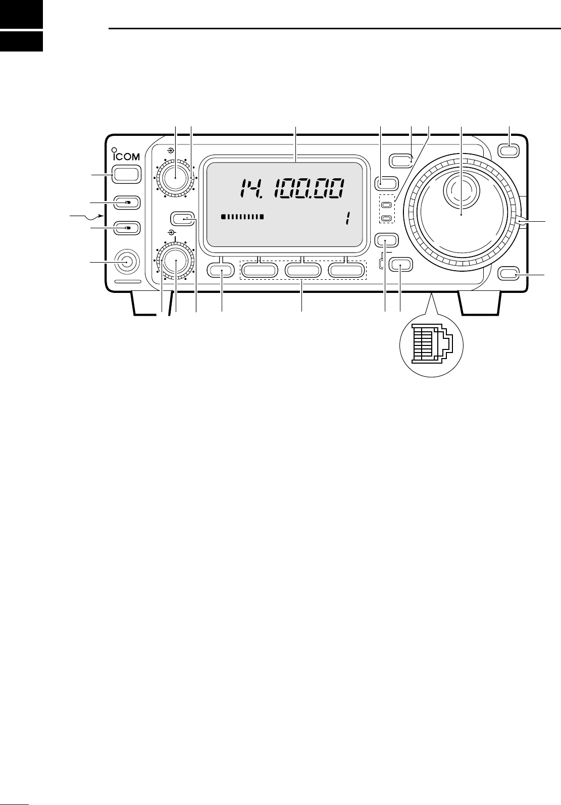
■FFrroonntt ppaanneell
qPPOOWWEERR SSWWIITTCCHH [[PPOOWWEERR]] (p. 15)
Turns power ON and OFF.
•Push momentarily to turn power ON.
•Push for 2 sec. to turn power OFF.
wAAFF GGAAIINN CCOONNTTRROOLL [[AAFF]] (inner control; p. 15)
Rotate clockwise to increase the audio output from
the speaker; rotate counterclockwise to decrease
the audio output from the speaker.
eRRFF GGAAIINN CCOONNTTRROOLL//SSQQUUEELLCCHH CCOONNTTRROOLL
[[RRFF//SSQQLL]] (outer control; p. 22)
➥Adjusts the squelch threshold level (to mute
noise when receiving no signal) in all modes.
➥This control can be used for RF gain control to
adjust receiver gain manually.
•RF gain selection can be set in initial set mode (p. 50).
• RF gain is usable in SSB/CW/RTTY modes only.
rFFUUNNCCTTIIOONN DDIISSPPLLAAYY
Shows the operating frequency, dot matrix indica-
tions, selected memory channel, etc. See p. 7 for
details.
tTTUUNNIINNGG SSTTEEPP SSWWIITTCCHH [[TTSS]] ((pgs. 17, 18)
➥Push momentarily to cycle between 1 Hz/10 Hz,
programmable and 1 MHz tuning steps.
•1 and 10 Hz steps are only available in SSB, CW and
RTTY modes; 1 MHz steps are only available in FM,
WFM and AM modes.
➥Push for 2 sec. to toggle between 1 and 10 Hz
steps, or; when the programmable tuning steps is
indicated, push for 2 sec. to enter programmable
tuning step mode.
yMMOODDEE SSWWIITTCCHH [[MMOODDEE]] (p. 19)
➥Push momentarily to cycle through the operating
modes:
USB/LSB ➧CW/CWå➧RTTY/åRTTY ➧
➧FM/WFM/AM
➥Push and hold for 2 sec. to toggle between the
following operating modes:
USB ↔LSB
CW ↔CWå
RTTY ↔åRTTY
FM →WFM →AM →FM, etc.
u
RREECCEEIIVVEE//TTRRAANNSSMMIITT IINNDDIICCAATTOORRSS [[RRXX]]//[[TTXX]]
[RX] lights green while receiving (and squelch
opens); [TX] lights red while transmitting.
iMMAAIINN DDIIAALL
Changes the displayed frequency, selects initial set
mode items, etc.
o
UUPP//DDOOWWNN ((BBAANNDD)) SSWWIITTCCHHEESS [[Y//Z((BBAANNDD))]]
➥Push to select a band.
•Can also be used to advance quick set mode items,
initial set mode items, etc.
➥Push and hold to scroll through the bands con-
tinuously.
!0 MMAAIINN DDIIAALL TTEENNSSIIOONN LLAATTCCHH
Selects the main dial tension.
•2 positions are available.
!1 MMIICCRROOPPHHOONNEE CCOONNNNEECCTTOORR (p. 8)
Modular-type microphone connector—connects
the supplied microphone (HM-103).
•The optional OPC-589 can be used to connect an 8-pin
microphone such as the SM-8 or SM-20, if desired.
•A microphone connector is also available on the rear
1
1PPAANNEELL DDEESSCCRRIIPPTTIIOONN
HF/VHF/UHF TRANSCEIVER i706MK™G
AF
RIT/
SUB
MENU F-1 F-2 F-3
MODE
BAND
BAND
Y
Z
TS
DISPLAY
LOCK
RX
TX
M-CH
PHONES
TUNER/CALL
P.AMP/ATT
POWER
SHIFT
RF/SQL
q
w e rtyio
o
!1
!2!3!4!5!6!7!8
!9
@0
@2
@1 !0
u
CH
VFO A
P
O
S1
5
53792040
10
60dB
USB
M1 SPL A/B A=B
IC-706MKIIG.qxd 02.3.27 13:53 Page 1

2
1
PANEL DESCRIPTION
panel. DO NOT connect 2 microphones simultaneously.
!2 LLOOCCKK SSWWIITTCCHH [[LLOOCCKK]]
➥Push momentarily to turn the dial lock function
ON and OFF.
•The dial lock function electronically locks the main
dial.
➥When the optional UT-102
VOICE SYNTHESIZER
UNIT
is installed (p. 52), push for 2 sec. to have the
frequency, etc. announced.
•UT-102 operation can be adjusted in initial set mode
(pgs. 53, 54).
!3 DDIISSPPLLAAYY SSWWIITTCCHH [[DDIISSPP]] (p. 68)
➥Push momentarily to select one of the three
menu sets: M1 to M4, S1 to S4 and G1 to G4.
➥Push for 2 sec. to select quick set mode.
!4
FFUUNNCCTTIIOONN SSWWIITTCCHHEESS [[FF11]]//[[FF22]]//[[FF33]] (pgs. 3, 4, 68)
Push to select the function indicated in the dot
matrix display above these switches.
•Functions vary depending on the menu set selected.
!5 MMEENNUU SSWWIITTCCHH [[MMEENNUU]] (p. 68)
➥
P
ush this switch one or more times to select
menus within a menu set (M, Sor G), or push to
advance through the quick set mode and initial
set mode displays.
➥Push and hold to jump between two different
function menu sets.
!6 RRIITT//SSUUBB DDIIAALL SSWWIITTCCHH [[RRIITT//SSUUBB]] (p. 20)
➥Push to toggle the RIT or SUB DIAL function ON
and OFF—initial set mode is used to select the
desired action*.
•Lights green when the SUB DIAL function is ON;
lights red when the RIT function is ON.
•Use the [M-CH] control to vary the RIT frequency or
SUB DIAL frequency (see above).
➥When the RIT function is ON, push for 2 sec. to
add or subtract the shifted frequency to the oper-
ating frequency.
*Even if RIT is selected in initial set mode, RIT cannot be
selected when operating AM, FM or WFM modes.
!7
SSHHIIFFTT CCOONNTTRROOLL [[SSHHIIFFTT]] (outer control; p. 20)
Shifts the center frequency of the receiver’s IF
passband.
•Rotate the control clockwise to shift the center frequen-
cy higher, or rotate the control counterclockwise to shift
the center frequency lower.
•When the graphic menu display (G2) is selected, the IF
passband is graphically displayed and changes in
accordance with the [SHIFT] control (see p. 20).
!8 MM--CCHH CCOONNTTRROOLL [[MM--CCHH]] (inner control)
➥
When the RIT or SUBDIAL functions are OFF,
rotate to select a memory channel number (p. 35).
➥Shifts the receive frequency while the RIT func-
tion is ON in SSB, CW and RTTY modes (see
below and p. 20).
•RIT variable range is ± 9.99 kHz
➥Changes the operating frequency in the select-
ed tuning steps while the SUB DIAL function is
ON (p. 18).
!9 HHEEAADDPPHHOONNEE JJAACCKK [[PPHHOONNEESS]] (p. 12)
Accepts headphones with 4–16 Ωimpedance.
•When headphones are connected, no receive audio
comes from the speaker.
•When the PHONES/SPEAKER switch on the back of the
front panel is set to the [SPEAKER] position, an external
speaker can be connected. This is convenient for mobile
or outdoor operation.
@0 TTUUNNEERR//CCAALLLL SSWWIITTCCHH [[TTUUNNEERR//CCAALLLL]]
(pgs. 26, 27)
➥During HF/50 MHz operation, push this switch
momentarily to toggle the automatic antenna
tuner function ON/OFF.
•An optional antenna tuner must be connected.
➥During HF/50 MHz operation, push this switch for
2 sec. to manually tune the antenna.
•An optional antenna tuner must be connected.
➥During 144/430 MHz operation, push this switch
momentarily to select the call channel (or the pre-
vious channel/frequency when the call channel is
already selected). (p. 39)
•“C1” is the 144 MHz call channel and “C2” is the 430
MHz call channel.
@1
FFRROONNTT PPAANNEELL LLAATTCCHH (p. 10)
Pull away from the transceiver (towards yourself
when looking at the front of the transceiver) to
detach the front panel from the main body of the
transceiver.
@2
PPRREEAAMMPP//AATTTTEENNUUAATTOORR SSWWIITTCCHH [[PP..AAMMPP//AATTTT]]
(p. 21)
➥Push momentarily to turn the preamp ON or OFF.
➥Push and hold to turn the 20 dB attenuator ON;
push momentarily to turn the attenuator OFF.
•Lights green when the preamp is ON; lights red when
the 20 dB attenuator is ON.
LOCK
Lights while the lock
function is activated.
RIT
SUB
Lights red while the RIT function is activated;
green while the SUB DIAL function is activated.
TUNER/CALL
Lights while the automatic
tuning function is activated.
P.AMP/ATT
Lights green while the preamp is activated;
lights red while the attenuator is activated.
IC-706MKIIG.qxd 02.3.27 13:53 Page 2
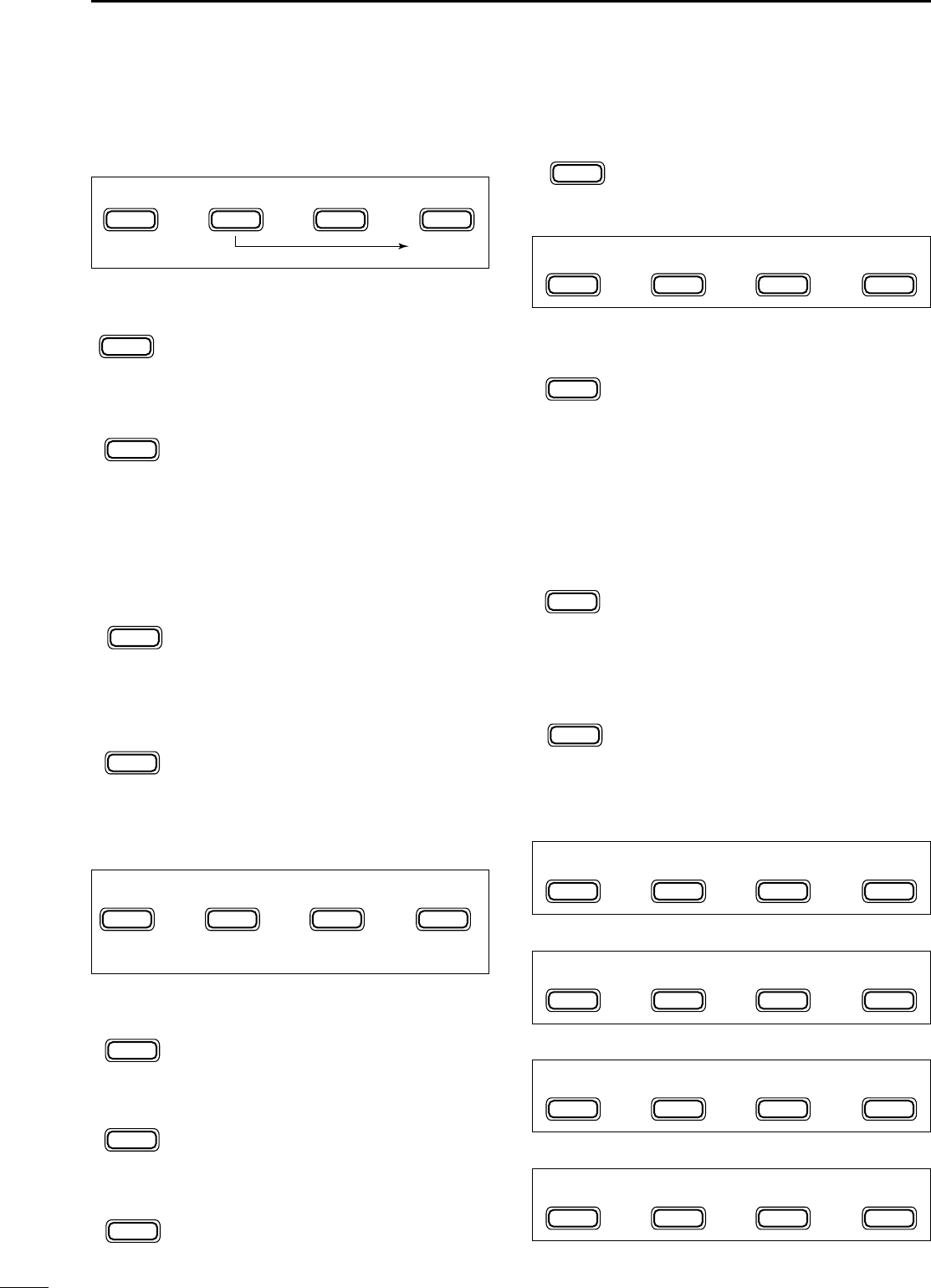
■FFuunnccttiioonn sswwiittcchheess
DMM11 FFUUNNCCTTIIOONNSS
SSPPLLIITT OOPPEERRAATTIIOONN (p. 29)
Toggles the split function ON and OFF.
•“ä”appears when the split function is ON.
•The function of [F-3] changes to XFC when the
split function is ON.
VVFFOO AA//BB SSEELLEECCTTIIOONN(p. 16)
➥Toggles between VFO A and VFO B in
VFO mode.
➥Toggles between transmission VFO and
reception VFO during split operation.
➥Toggles between the transmit and
receive frequencies (and modes) of
memory channels when the split func-
tion is turned ON.
VVFFOO EEQQUUAALLIIZZAATTIIOONN (p. 16)
Equalizes the frequency and operating
mode of the two VFO’s.
•The rear (undisplayed) frequency and operat-
ing mode are equalized to the front (displayed)
VFO frequency and operating mode.
TTRRAANNSSMMIITT FFRREEQQUUEENNCCYY CCHHEECCKK (p. 29)
Appears when the split function is turned
ON—monitors the transmit frequency
when pushed and held.
•While pushed, the transmit frequency can be
changed with the main dial.
DMM22 FFUUNNCCTTIIOONNSS
MMEEMMOORRYY WWRRIITTEE (p. 40)
Stores the displayed frequency and oper-
ating mode into the displayed memory
channel.
MMEEMMOORRYY TTRRAANNSSFFEERR (p. 41)
Transfers the frequency and operating
mode in the selected memory channel to a
VFO.
VVFFOO//MMEEMMOORRYY (p. 39)
Toggles between VFO and memory
modes.
MMEEMMOORRYY CCLLEEAARR (p. 39)
Clears the selected memory channel’s
contents.
•“}” appears.
DMM33 FFUUNNCCTTIIOONNSS
NNAARRRROOWW FFIILLTTEERR (p. 23)
Toggles the narrow filter (or wide
filter—push for 2 sec.) ON and OFF.
•“ã”appears when the narrow filter is ON; “ç”
appears when the wide filter is ON.
•An optional narrow filter and presetting in initial
set mode (p. 51) is necessary to use the fol-
lowing:
CW/RTTY narrow: FL-100, FL-101 or FL-232
SSB narrow: FL-223
SSB wide: FL-103
NNOOIISSEE BBLLAANNKKEERR (p. 21)
Turns the noise blanker ON and OFF.
•The noise blanker does not function in FM and
WFM modes; the “AM Noise blanker” item in
initial set mode must be set to ON for the noise
blanker to work in AM mode (p. 53).
MMEETTEERR SSEELLEECCTTIIOONN(p. 25)
Selects the type of meter displayed (dur-
ing transmit) in the function display.
•Power, ALC or SWR metering can be selected.
•Only an S-meter is available for receive.
DMM44 FFUUNNCCTTIIOONNSS
DURING SSB/AM OPERATION:
DURING CW OPERATION:
DURING RTTY OPERATION:
DURING FM OPERATION:
F-3
MET
F-2
NB
F-1
FIL
F-2
MCL
F-3
V/M
F-2
MÜV
F-1
MW
F-3
XFC
F-3
A=B
F-2
A/B
F-1
SPL
3
1PANEL DESCRIPTION
MENU
M3
F-1
FIL
F-2
NB
F-3
MET
MENU
M4
F-1
VOX
F-2
COM
F-3
AGC
MENU
M4
F-1 F-2
BRKi/4
F-3
AGC
MENU
M2
F-1
MW
F-2
MÜV
MCL
F-3
V/M
(in memory mode)
MENU
M4
F-1
1/4
F-2 F-3
AGC
MENU
M4
F-1
VOX
F-2
TSQ
F-3
TON
MENU
M1
F-1
SPL
F-2
A/B
XFC
F-3
A=B
IC-706MKIIG.qxd 02.3.27 13:53 Page 3
4
1
PANEL DESCRIPTION
VVOOXX FFUUNNCCTTIIOONN (p. 26)
Toggles the VOX function ON and OFF.
•The [VOX GAIN] and [ANTI VOX] are available
on the side panel.
•VOX delay can be set in quick set mode
(p. 48).
SSPPEEEECCHH CCOOMMPPRREESSSSOORR (p. 26)
Toggles the speech compressor ON and
OFF.
•The [COMP GAIN] control is available on the
side panel.
AAGGCC (p. 21)
Changes the time constant of the AGC cir-
cuit.
BBRREEAAKK--IINN (p. 33)
Selects semi break-in, full break-in (QSK)
and break-in OFF
•“BK” or “F-BK” appears when selecting semi
break-in or full break-in, respectively.
•An external switch, such as a foot switch, is
necessary to connect to the ACC socket (pin
3, pin 7 or RTTY SEND—see p. 35) to use no
break-in operation.
11//44 FFUUNNCCTTIIOONN (p. 36)
Toggles the 1/4 function ON and OFF.
•When the 1⁄4function is ON, a bar appears
under the 1⁄4indication and fine tuning can be
used.
TTOONNEE SSQQUUEELLCCHH (p. 31)
Toggles the tone squelch function ON and
OFF (a tone squelch frequency must be
selected in Quick Set mode).
•“FM-TSQL” appears when the function is ON.
RREEPPEEAATTEERR TTOONNEE OOPPEERRAATTIIOONN (p. 30)
➥Toggles the subaudible tone encoder
for repeater use ON and OFF.
•“FM-T” appears when the function is ON.
➥Transmits a 1750 Hz tone burst when
pushed and held during transmission.
•Tone frequencies or tone burst can be set in
initial set mode (p. 49).
DSS11 FFUUNNCCTTIIOONNSS
MMEEMMOORRYY WWRRIITTEE (p. 40)
Stores the displayed frequency and oper-
ating mode into the displayed memory
channel.
MMEEMMOO PPAADD WWRRIITTEE (p. 42)
Stores the displayed frequency and oper-
ating mode into a memo pad.
MMEEMMOO PPAADD RREEAADD (p. 42)
Calls up a memo pad.
DSS22 FFUUNNCCTTIIOONNSS
SSCCAANN (p. 44)
Starts and stops the scan function.
PPRRIIOORRIITTYY WWAATTCCHH (p. 44)
Starts and stops priority watch.
SSEELLEECCTT SSCCAANN (p. 44)
Toggles the select setting ON and OFF for
the selected memory channel.
VVFFOO//MMEEMMOORRYY (p. 44)
Toggles between VFO and memory
modes.
DSS33 FFUUNNCCTTIIOONNSS
QQUUIICCKK BBAANNDD CCHHAANNGGEE FFUUNNCCTTIIOONN (p. 19)
This item provides access to the band stacking regis-
ter. By default the 7, 50 and 144 MHz bands are dis-
played. Push [F-1] to [F-3] for 2 sec. to select a new
band if desired.
•A mode is memorized along with the frequency for each
band.
DSS44 FFUUNNCCTTIIOONNSS (may be optional for some ver.)
AAUUTTOOMMAATTIICC NNOOTTCCHH FFIILLTTEERR (p. 24)
This function automatically attenuates beat
tones, tuning signals, etc., even if they are
moving.
NNOOIISSEE RREEDDUUCCTTIIOONN (p. 24)
This function reduces noise components
and picks out desired signals which are
buried in the noise.
NNOOIISSEE RREEDDUUCCTTIIOONN DDIISSPPLLAAYY (p. 24)
This displays the noise reduction level
when using the noise reduction function.
F-3
NRL
F-2
NR
F-1
ANF
F-3
V/M
F-2
SEL
F-2
PRI
F-1
SCN
F-3
MPR
F-2
MPW
F-1
MW
F-3
TON
F-2
TSQ
F-1
1/4
F-2
BRK
F-3
AGC
F-2
COM
F-1
VOX
MENU
S1
F-1
MW
F-2
MPW
F-3
MPR
MENU
S2
F-1
SCN
F-2
PRI
SEL
F-3
V/M
(in memory mode)
MENU
S3
F-1
7
F-2
50
F-3
144
MENU
S4
F-1
ANF
F-2
NR
F-3
NRL
IC-706MKIIG.qxd 02.3.27 13:53 Page 4
5
1PANEL DESCRIPTION
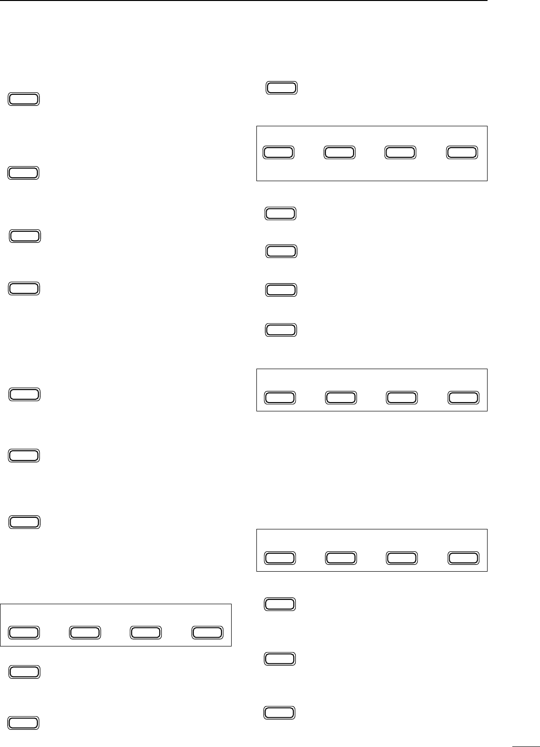
■RReeaarr aanndd ssiiddee ppaanneellss
qGGRROOUUNNDD TTEERRMMIINNAALL [[GGNNDD]] (p. 9)
Connect this terminal to a ground to prevent electri-
cal shocks, TVI, BCI and other problems.
w
AANNTTEENNNNAA CCOONNNNEECCTTOORRSS [[AANNTT 11]],, [[AANNTT 22]] (p. 11)
Accept a 50 Ωantenna with an PL-259 type plug.
•[ANT 1] is for connection to an HF/50 MHz antenna.
•[ANT 2] is for connection to 144 MHz antenna.
•These connectors are switched above or below 60 MHz.
e
DDAATTAA JJAACCKK [[DDAATTAA]] (p. 12)
6-pin min DIN jack to connect a TNC, etc. for packet
operation.
r
AACCCCEESSSSOORRYY SSOOCCKKEETT [[AACCCC]] (p. 6)
Enables connection to external equipment such as
a TNC for data communications, a linear amplifier or
an automatic antenna selector/tuner, etc.
•See page at right for socket information.
t
RRTTTTYY JJAACCKK [[RRTTTTYY]] (p. 35)
Connects an external terminal unit for RTTY (FSK)
operation.
•The keying polarity and mark/shift frequencies can be
selected in quick set mode (p. 48).
yCCII--VV RREEMMOOTTEE CCOONNTTRROOLL JJAACCKK [[RREEMMOOTTEE]]
(p. 45)
Designed for use with a personal computer for
remote operation of transceiver functions.
uMMIICCRROOPPHHOONNEE CCOONNNNEECCTTOORR [[MMIICC]] (p. 11)
Accepts the supplied microphone (connected in
parallel with the front panel’s [MIC] connector).
•See pgs. 1 and 2 for microphone notes.
•See p. 8 for microphone connector information.
iEELLEECCTTRROONNIICC KKEEYYEERR JJAACCKK [[KKEEYY]] (p. 33)
Accepts a paddle to activate the internal electronic
keyer.
•Selection between the internal electronic keyer and
straight key operation can be made in quick set mode.
(p. 49)
oDDCC PPOOWWEERR SSOOCCKKEETT [[DDCC1133..88VV]] (p. 13)
Accepts 13.8 V DC through the supplied DC power
cable.
!0
EEXXTTEERRNNAALL SSPPEEAAKKEERR JJAACCKK [[EEXXTT SSPP]] (p. 12)
Accepts a 4–16 Ωspeaker.
!1
TTUUNNEERR CCOONNTTRROOLL SSOOCCKKEETT [[TTUUNNEERR]] (p. 12)
Accepts the control cable from an optional AH-3
HF
AUTOMATIC ANTENNA TUNER
.
!2
SSPPEEEECCHH CCOOMMPPRREESSSSIIOONN LLEEVVEELL CCOONNTTRROOLL
[[CCOOMMPP GGAAIINN]] (p. 26)
Adjusts the compression level.
•This control is available only when the speech compres-
sor is ON.
COMP
GAIN /SIDE T
BEEP
DC 13.8V
EXT SP
MIC KEY
TUNER
ANT 1
ANT 2
GND
q
w
er ui
o
!2 !3
!0!1
ty
When connecting
a straight key
When connecting
a paddle
(dot)
(com)
(dash)
(⊕)
Rear panel view
Recommended
level
Counterclockwise
decreases Clockwise
increases
COMP
GAIN /SIDE T
BEEP
IC-706MKIIG.qxd 02.3.27 13:53 Page 5
•AACCCC SSOOCCKKEETT
•WWhheenn ccoonnnneeccttiinngg tthhee AACCCC ccoonnvveerrssiioonn ccaabbllee ((OOPPCC--559999))
6
1
PANEL DESCRIPTION
!3
BBEEEEPP//SSIIDDEETTOONNEE CCOONNTTRROOLL [[BBEEEEPP//SSIIDDEETTOONNEE]]
Adjusts the beep tone and CW side tone audio lev-
els.
TECHNICAL INFORMATION
AACCCCPPIINN ##NNAAMMEEDDEESSCCRRIIPPTTIIOONNSSPPEECCIIFFIICCAATTIIOONNSS
CCOOLLOORR
18 V Regulated 8 V output. Output voltage : 8 V ±0.3 V
Output current : Less than 10 mA brown
2GND Connects to ground. red
3 HSEND
Input/output pin (HF/50 MHz).
Goes to ground when transmitting.
When grounded, transmits (connected to 8V
line thru 2.2 kΩresistance/144 MHz operation).
Ground level : –0.5 V to 0.8 V
Input current : Less than 20 mA
(HF/50 MHz bands)
orange
4 BDT Data line for the optional AT-180. yellow
5BAND Band voltage output.
(Varies with amateur band) Output voltage : 0 to 8.0 V green
6ALC ALC voltage input. Control voltage : –4 to 0 V
Input impedance : More than 10 kΩblue
7VSEND
Input/output pin (144 MHz).
Goes to ground when transmitting.
When grounded, transmits
(connected to 8V
line thru 2.2 kΩresistance/HF•50 MHz operation)
.
Ground level : –0.5 V to 0.8 V
Input current : Less than 20 mA
(144 MHz band)
purple
813.8 V 13.8 V output when power is ON. Output current :Max. 1 A gray
9TKEY Key line for the AT-180. white
10 FSKK RTTY keying input.
Connected in parallel to the [RTTY] jack.
Ground level : –0.5 to 0.8 V
Input current : Less than 10 mA black
11 MOD Modulator input.
Input impedance : 10 kΩ
Input level : Approx. 100 mV
rms
pink
12 AF AF detector output.
Fixed, regardless of [AF] position.
Output impedance : 4.7 kΩ
Output level : 100 to 350 mV rms
light
blue
13 SQLS Squelch output.
Goes to ground when squelch opens.
SQL open : Less than 0.3 V/5 mA
SQL closed : More than 6.0 V/100 µA
light
green
Rear panel
view
1234
8765
9
10 11 12
13
Color refers to the
cable strands of the
supplied cable.
ACC 1
ACC 2
➀ FSKK ➄ AF
➁ GND ➅ SQLS
➂ HSEND ➆ 13.8 V
➃ MOD ➇ ALC
➀ 8 V ➄ ALC
➁ GND ➅ VSEND
➂ HSEND ➆ 13.8 V
➃ BAND
1
1
2
2
3
3
4
4
8
8
7
7
6
6
5
5
9
10 11 12
13
1
2
3
4
76
5
IC-706MKIIG.qxd 02.3.27 13:53 Page 6
7
1PANEL DESCRIPTION
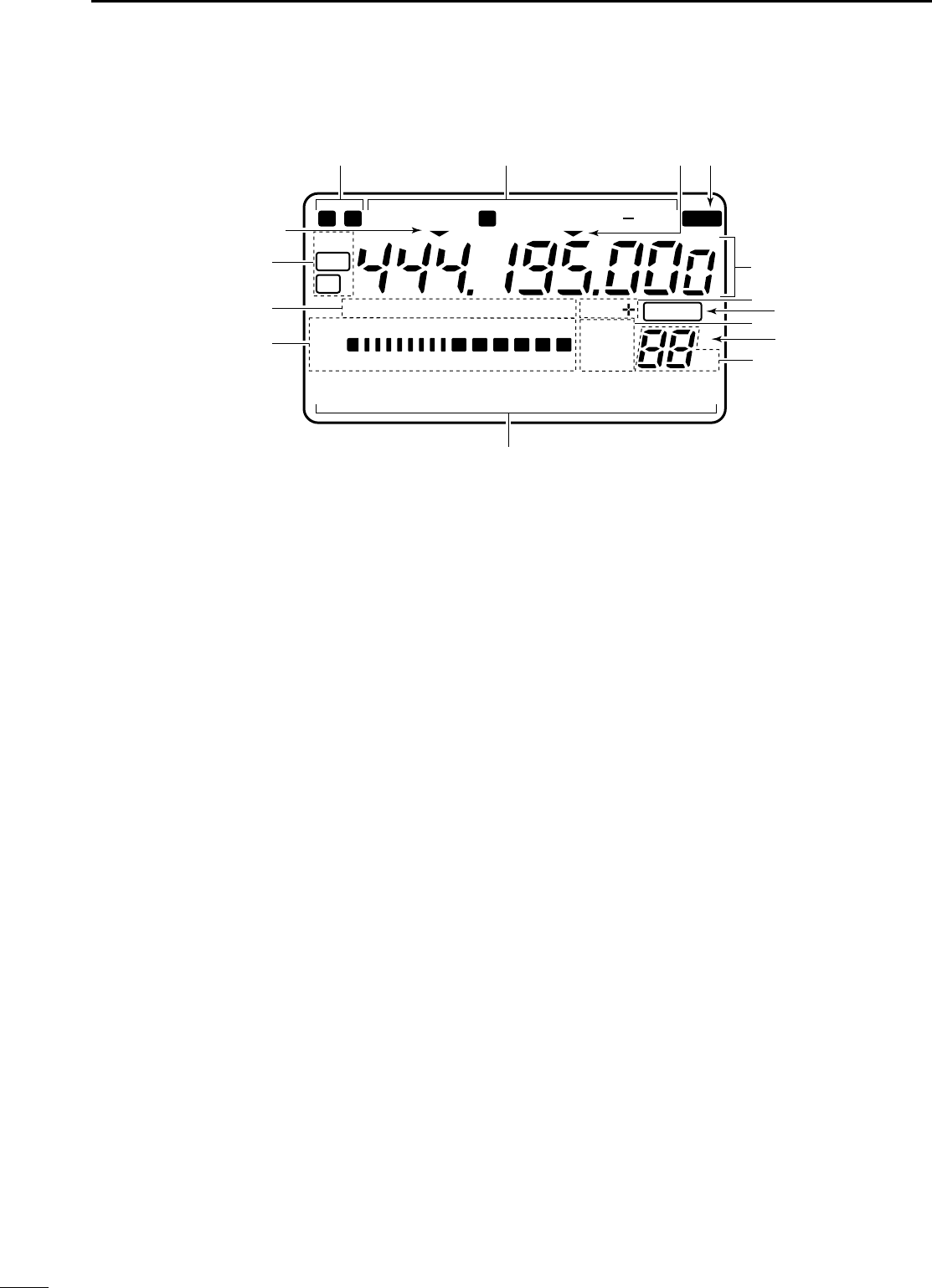
■FFuunnccttiioonn ddiissppllaayy
qNNAARRRROOWW//WWIIDDEE FFIILLTTEERR IINNDDIICCAATTOORRSS
➥“ã” appears when selecting AM narrow or FM
narrow modes.
➥When installing an optional narrow filter, narrow
mode can be selected in CW, RTTY and SSB
modes.
•When the SSB wide filter is installed, “ç” appears
during wide mode selection.
wMMOODDEE IINNDDIICCAATTOORRSS
Show the operating mode.
ePPRROOGGRRAAMMMMAABBLLEE//11 MMHHzz TTUUNNIINNGG SSTTEEPP
IINNDDIICCAATTOORRSS
➥➌a appears when the programmable tuning step
is selected.
➥➌b appears when the 1 MHz tuning step is
selected.
rSSPPLLIITT IINNDDIICCAATTOORR
Shows that the split frequency function is activated.
tFFRREEQQUUEENNCCYY RREEAADDOOUUTT
Shows the operating frequency.
•“C” appears in place of the 1 Hz digit when the call chan-
nel is selected.
yDDUUPPLLEEXX IINNDDIICCAATTOORRSS
➥“DUP+” appears during plus duplex operation.
➥“DUP–” appears during minus duplex operation.
uBBLLAANNKK IINNDDIICCAATTOORR
Shows that the displayed memory channel is not
programmed.
•This indicator appears both in VFO and memory modes.
iVVFFOO//MMEEMMOORRYY IINNDDIICCAATTOORRSS
VFO A or B appears when VFO mode is selected;
MEMO appears when memory mode is selected.
oSSEELLEECCTT IINNDDIICCAATTOORR
Shows that the displayed memory channel is desig-
nated as a select memory channel.
!0 MMEEMMOORRYY CCHHAANNNNEELL NNUUMMBBEERR RREEAADDOOUUTT
Shows the selected memory channel number.
!1 DDOOTT MMAATTRRIIXX IINNDDIICCAATTOORRSS
These alphanumeric readouts show a variety of
information such as current functions of the “F”
keys [F1] to [F3], memory channel names, set mode
items, etc. See p. 68 for an overview of these indi-
cators.
!2 MMEETTEERR RREEAADDOOUUTTSS
➥Functions as an S-meter while receiving.
➥Functions as a power, ALC or SWR meter while
transmitting.
NNoottee::The SWR meter does not function in the 144
MHz band.
!3 FFUUNNCCTTIIOONN IINNDDIICCAATTOORRSS
➥“NB” appears when the noise blanker is activat-
ed.
➥“VOX” appears when the VOX function is select-
ed.
➥“F-BK” appears when full break-in operation is
selected and only “BK” appears when semi
break-in operation is selected.
➥“COM” appears when the speech compressor is
activated.
➥“FAGC” appears when the fast AGC function is
selected.
!4 DDSSPP IINNDDIICCAATTOORRSS
Appear when the optional DSP unit is installed and
activated.
N W R SPL
LSB
DSP
NB VOX F-BK COM F
S
CH
VFO A
DUP
VFO B
MEMO
AGC
ALC
SWR PO
S1
1 1.5 2 3 5
53792040
10
∞
60dB
USBCW R
TT
Y
AMWFM TSQL
BLANK
ANF
NR
qw r
t
yu
o
!1
!2
!3
!4
i
!0
ea
eb
M1 SPL A/B A=B
IC-706MKIIG.qxd 02.3.27 13:53 Page 7
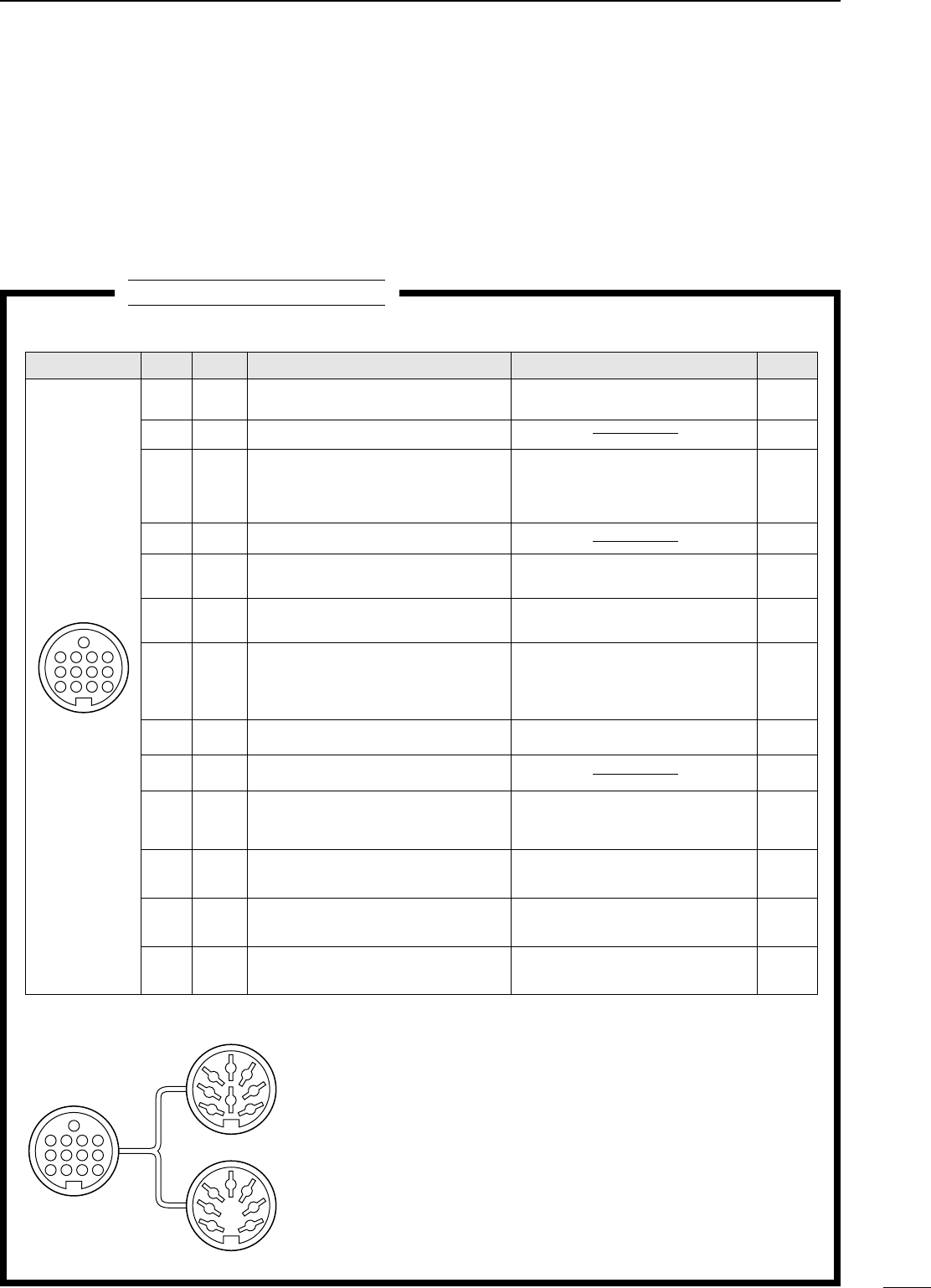
•MMIICCRROOPPHHOONNEE CCOONNNNEECCTTOORR
8
1
PANEL DESCRIPTION
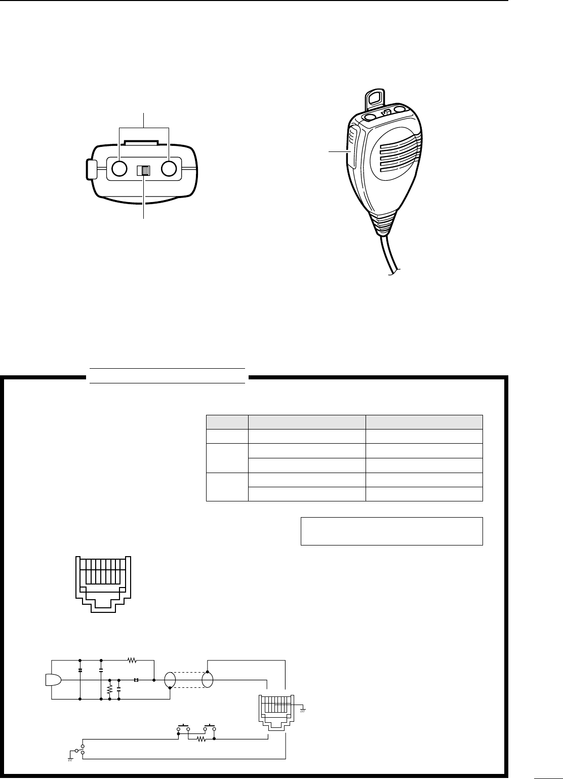
■MMiiccrroopphhoonnee ((HHMM--110033))
qUUPP//DDOOWWNN SSWWIITTCCHHEESS [[UUPP]]//[[DDNN]]
Change the operating frequency.
•Push and hold to change the frequency continuously.
•Tuning step is 50 Hz when no TS indicator appears.
wLLOOCCKK SSWWIITTCCHH [[LLOOCCKK]]
Locks the [UP]/[DN] switches.
ePPTTTT SSWWIITTCCHH [[PPTTTT]]
Push and hold to transmit; release to receive.
DN UP
LOCK
OFF ON
➊
➋
➌
TECHNICAL INFORMATION
PPIINN NNOO..FFUUNNCCTTIIOONNDDEESSCCRRIIPPTTIIOONN
1+8 V DC output Max. 10 mA
2Frequency up Ground
Frequency down Ground through 470 Ω
8Squelch open “LOW” level
Squelch closed “HIGH” level
➃ PTT
➅ Microphone input
➁ Frequency up/down
➆ GND
➀ +8 V DC output
➇ Squelch switch
➄ GND (microphone ground)
➂ AF output
Rear panel view
1 2345678
•HHMM--110033 SSCCHHEEMMAATTIICC DDIIAAGGRRAAMM
4700p
4700p
10µ0.33µ+
+
MICROPHONE
MIC
ELEMENT
2k
2.2k
470
DOWN UP
PTT RECEIVE
TRANSMIT
MICROPHONE
CABLE
MICROPHONE PLUG
12345678
CCaauuttiioonn::DO NOT short pin 1 to ground as
this can damage the internal 8 V regulator.
IC-706MKIIG.qxd 02.3.27 13:53 Page 8
9
2IINNSSTTAALLLLAATTIIOONN AANNDD CCOONNNNEECCTTIIOONNSS
■UUnnppaacckkiinngg
After unpacking, immediately report any damage to
the delivering carrier or dealer. Keep the shipping car-
tons.
For a description and a diagram of accessory equip-
ment included with the IC-706MKIIG, see UNPACK-
ING on p. ii of this manual.
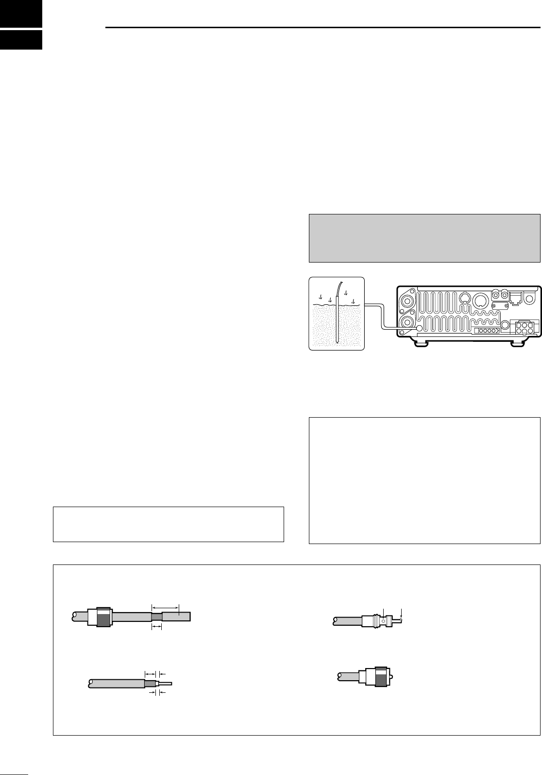
■GGrroouunnddiinngg
To prevent electrical shock, television interference
(TVI), broadcast interference (BCI) and other prob-
lems, ground the transceiver through the GROUND
terminal on the rear panel.
For best results, connect a heavy gauge wire or strap
to a long earth-sunk copper rod. Make the distance
between the GROUND terminal and ground as short
as possible.
■AAnntteennnnaa
Select antenna(s), such as a well-matched 50 Ω
antenna, and feedline. The transmission line should
be a coaxial cable. 1.5 : 1 or better of Voltage
Standing Wave Ratio (VSWR) is recommended for
your required band. Of course, the transmission line
should be a coaxial cable.
CCAAUUTTIIOONN::Protect your transceiver from light-
ning using a lightning arrestor.
RWWAARRNNIINNGG::NNEEVVEERR connect the [GND]
terminal to a gas or electric pipe, since the connec-
tion could cause an explosion or electric shock.
30 mm
10 mm (soft solder)
10 mm
1–2 mm
solder solder
Soft
solder
Coupling ring
PL-259 CONNECTOR INSTALLATION EXAMPLE
➀➂
➃
➁
Slide the coupling ring
down. Strip the cable
jacket and soft solder.
Slide the connector
body on and solder it.
Screw the coupling ring
onto the connector
body.
Strip the cable as
shown at left. Soft
solder the center con-
ductor.
(10 mm ≈ 3⁄8 in)
AANNTTEENNNNAA SSWWRR
Each antenna is tuned for a specified frequency
range and SWR may be increased out-of-range.
When the SWR is higher than approx. 2.0 : 1, the
transceiver’s power drops to protect the final transis-
tors. In this case, an optional antenna tuner is useful
to match the transceiver and antenna. Low SWR
allows full power for transmitting even when using
the antenna tuner. The IC-706MKIIG has an SWR
meter to monitor the antenna SWR continuously.
IC-706MKIIG.qxd 02.3.27 13:53 Page 9
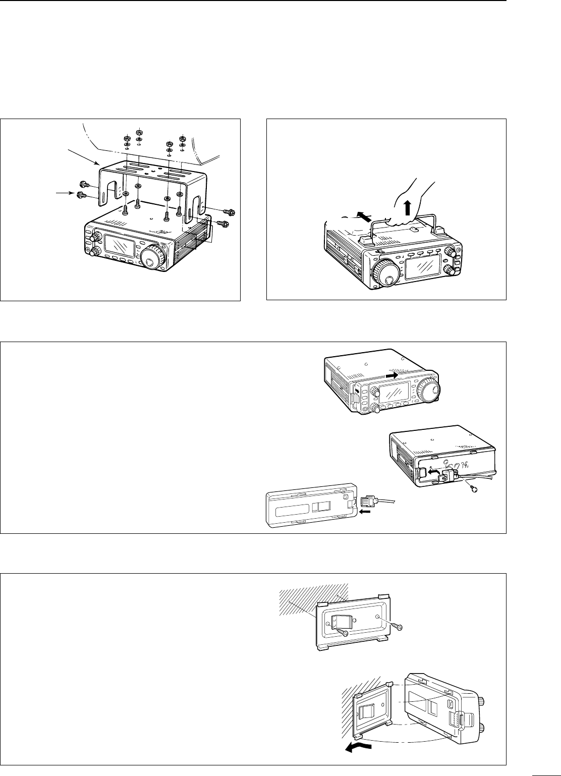
To raise the stand:
With the transceiver upside down, pull the stand
towards the rear panel and then upwards, as illus-
trated below.
10
2
INSTALLATION AND CONNECTIONS
■IInnssttaallllaattiioonn
DSSiinnggllee bbooddyy mmoouunnttiinnggDSSttaanndd
*CAUTION: Non-supplied screws (longer than 8 mm)
may damage the internal units.
MB-62
(optional)
Supplied with
the MB-62*
Pull back
then up
DFFrroonntt ppaanneell sseeppaarraattiioonn
DFFrroonntt ppaanneell mmoouunnttiinngg
➀While pulling the panel release button towards
you, slide the front panel to the right (fig. 1).
➁Attach the optional OPC-581 to the main body and
tighten the supplied screw as in fig. 2.
➂Attach the other end of the OPC-581 to the
detached front panel as in fig. 3.
➀Attach the MB-63 to a flat surface using the two
supplied screws (fig. 1).
➁Fix the detached front panel to the MB-63 as illus-
trated in fig. 2.
BBee ccaarreeffuullof the orientation of the MB-63, other-
wise, the front panel may become attached in the
opposite direction.
fig. 1
fig. 2
fig. 3
fig. 1
fig. 2
IC-706MKIIG.qxd 02.3.27 13:53 Page 10
11
2INSTALLATION AND CONNECTIONS
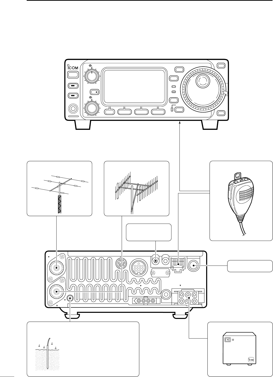
■RReeqquuiirreedd ccoonnnneeccttiioonnss
DC 13.8V
EXT SP
MIC KEY
TUNER
ANT 1
ANT 2
GND
HF/VHF/UHF TRANSCEIVER i706MK™G
AF
RIT/
SUB
MENU F-1 F-2 F-3
MODE Y
Z
TS
DISPLAY
LOCK
RX
TX
M-CH
PHONES
TUNER/CALL
P.AMP/ATT
POWER
SHIFT
RF/SQL
BAND
BAND
MICROPHONE (p. 8)
HF/50 MHz ANTENNA
RTTY TERMINAL
UNIT (p. 35)
2 m ANTENNA
PS-85
GROUND (p. 9)
HM-103
See p. 13 for details.
CW KEY (p. 33)
Use the heaviest gauge wire or
strap available and make the
connection as short as possible.
Grounding prevents electrical
shocks, TVI and other
problems.
IC-706MKIIG.qxd 02.3.27 13:53 Page 11
12
2
INSTALLATION AND CONNECTIONS
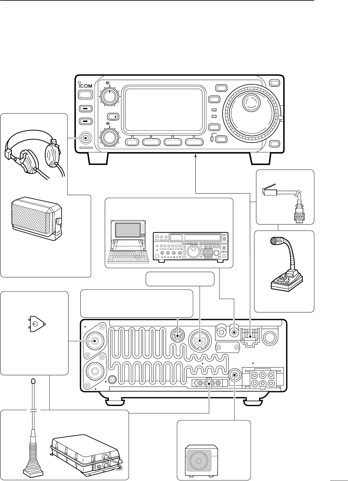
■AAddvvaanncceedd ccoonnnneeccttiioonnss
DC 13.8V
EXT SP
MIC KEY
TUNER
ANT 1
ANT 2
GND
OPC-589 (p. 65)
DESKTOP (p. 64)
MICROPHONE
SPEAKER
Selectable with the
[PHONE/SPEAKER] switch
on the back of the front panel.
ACC SOCKET (p. 6)
REMOTE (p. 45)
Used for computer control and transceive.
DATA JACK (p. 37)
6-pin mini DIN jack to connect to a
TNC, etc. for packet operation.
AH-3 (p. 14)
AH-2b
COAX ANTENNA
SWITCH
EXTERNAL
SPEAKER (p. 65)
HEADPHONES
SP-21
When using a 50 MHz
antenna separately
since the AH-3 can
only be used for the
HF bands.
or
HF/VHF/UHF TRANSCEIVER i706MK™G
AF
RIT/
SUB
MENU F-1 F-2 F-3
MODE Y
Z
TS
DISPLAY
LOCK
RX
TX
M-CH
PHONES
TUNER/CALL
P.AMP/ATT
POWER
SHIFT
RF/SQL
BAND
BAND
IC-706MKIIG.qxd 02.3.27 13:53 Page 12
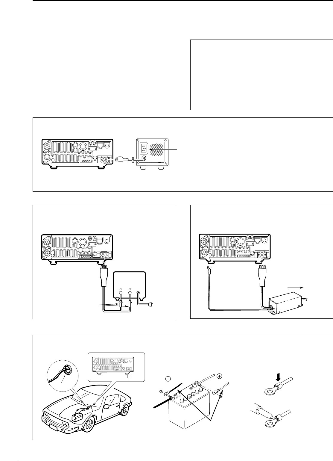
CONNECTING THE PS-125 / PS-85 DC POWER SUPPLY
PS-125 / PS-85
Connect to an AC outlet
using the supplied AC cable.
DC power cable
DC power
socket
CONNECTING A NON-ICOM
DC POWER SUPPLY (For Europe versions)
Transceiver
DC power
socket
To non-Icom
power supply
[GND]
OPC-639
CONNECTING A NON-ICOM
DC POWER SUPPLY
Transceiver
DC power
socket
To AC outlet
Supplied
DC power cable
13.8 V
Black
30 A fuses
Red
20 A
13
2INSTALLATION AND CONNECTIONS
■PPoowweerr ssuuppppllyy ccoonnnneeccttiioonnss
Use the optional PS-125 / PS-85 DC POWER SUPPLY
when operating the IC-706MKIIG with AC power.
Refer to the diagram below for connection.
CCAAUUTTIIOONN::Before connecting the DC power
cable, check the following important items. Make
sure:
•The [POWER] switch is OFF.
•Output voltage of the power source is 12–15 V
when you use a non-Icom power supply.
•DC power cable polarity is correct.
Red : positive (+) terminal
Black : negative (–) terminal
Grommet
CONNECTING A VEHICLE BATTERY
NEVER connect to
a 24 V battery.
Note: Use terminals for
the cable connections.
Crimp
Solder
Supplied
DC power cable
red
black
12 V
battery
NNoottee::When using the PS-125, the IC-
706MKIIG Europe version complies with
EMC directives even if the OPC-639 is
not used.
IC-706MKIIG.qxd 02.3.27 13:53 Page 13
14
2
INSTALLATION AND CONNECTIONS
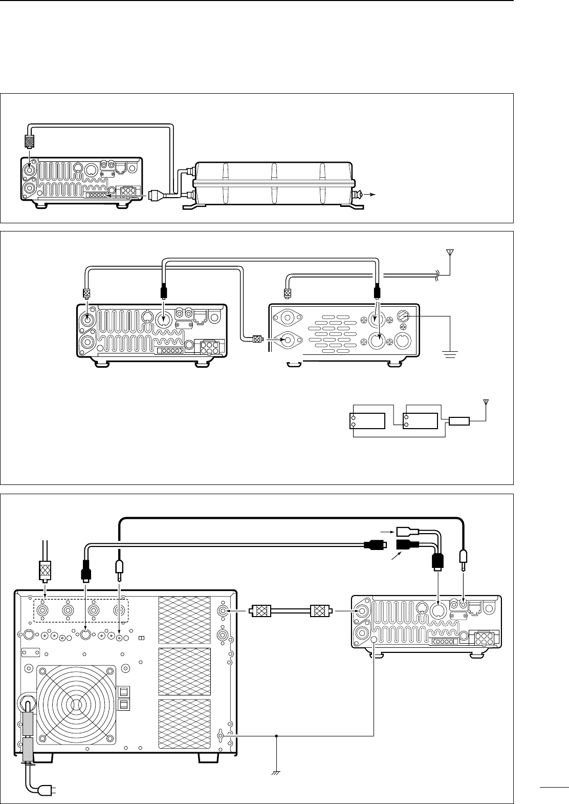
■EExxtteerrnnaall aanntteennnnaa ttuunneerrss aanndd lliinneeaarr aammpplliiffiieerr
AH-4
ANT 1
Transceiver
Coaxial cable
(from the AH-4)
To the AH-2b or
an antenna element
CONNECTING THE AH-4
The AH-4 can be used for the HF bands and 50
MHz band only.
CONNECTING THE AT-180
Ground
HF
to 6 m
antenna
[TRANSCEIVER]
[ANT 1] [ACC] [ACC]AT-180
ACC cable supplied with the AT-180
Coaxial cable supplied
with the AT-180
IC-706
one of two
connectors
ACC-1 REMOTE
INPUT-1 ANT1
ANT
Mini-plug cable
ACC cable
7-pin side
AC outlet (220–240 V)
IC-PW1
GND
GND
ACC REMOTE
Transceiver
Coaxial cable
To an
antenna OPC-599 conversion cable
CONNECTING THE IC-PW1
NNoottee::
•Turn the IC-706MKIIG’s power
OFF when connecting the AT-
180, otherwise, the CPU may
malfunction and the AT-180
may not function properly.
•The OPC-742 is required when
using bbootthhthe AT-180 and a 2
m linear amplifier.
DDoo nnoottconnect [ANT 2] to the
AT-180. When using an HF to 2 m
wide antenna, use a duplexer
between the AT-180 and antenna
since 2 m signals do not pass
through the AT-180.
[ANT 1]
Transceiver
Duplexer
HF to 2 m
antenna
AT-180
[ANT 2]
IC-706MKIIG.qxd 02.3.27 13:53 Page 14
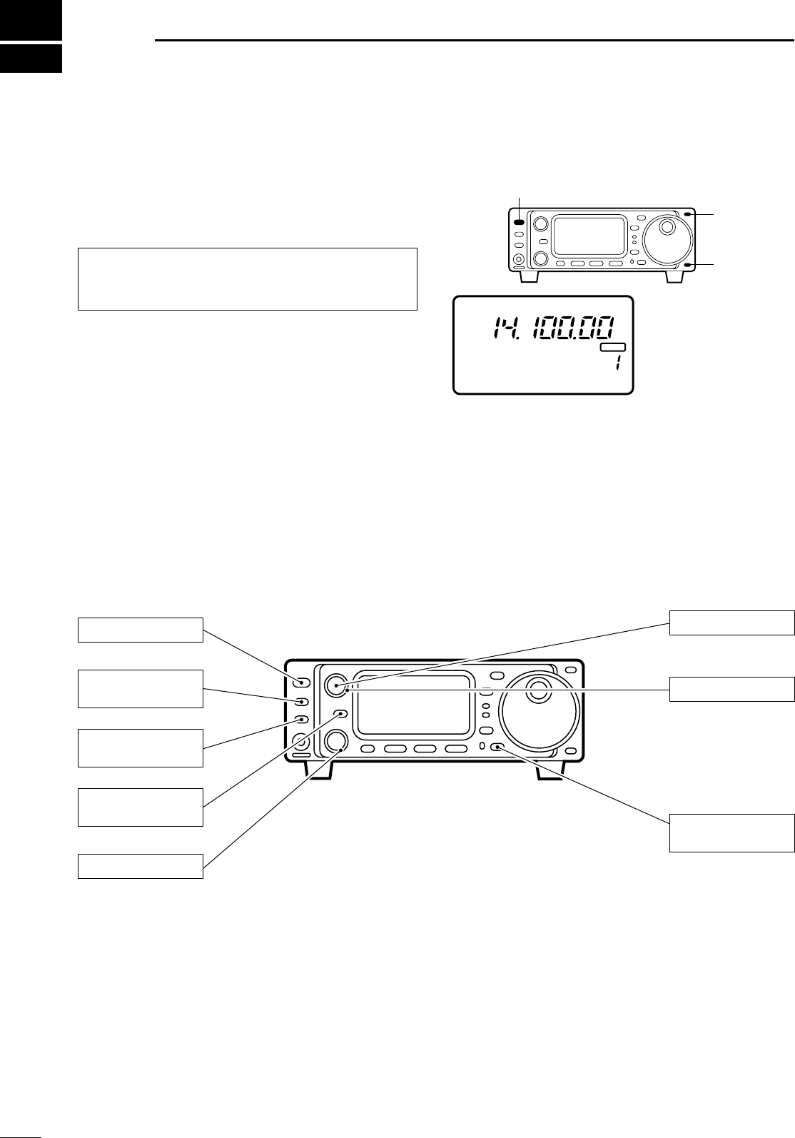
15
3FFRREEQQUUEENNCCYY SSEETTTTIINNGG
■WWhheenn ffiirrsstt aappppllyyiinngg ppoowweerr ((CCPPUU rreesseettttiinngg))
Before first applying power, make sure all connections
required for your system are complete by referring to
section 2. Then, reset the transceiver using the fol-
lowing procedure.
➀Make sure the transceiver power is OFF.
➁While pushing [Y] and [Z], push [POWER] to turn
power ON.
•The internal CPU is reset.
•The transceiver displays as shown at right when reset-
ting is complete.
DM1 ddiissppllaayy sseelleeccttiioonn
If you can’t figure out how to return to the M1 display:
While pushing [MENU], turn power ON.
■IInniittiiaall sseettttiinnggss
After resetting the transceiver, set controls and
switches as shown in the diagram below.
NNoottee::Resetting clears all programmed contents in
memory channels and returns all initial set mode and
quick set mode contents to their default values.
BLANK
CH
VFO A
S1 5379204060dB
USB
M1 SPL A/B A=B
The transceiver displays
its initial frequency and
mode.
[POWER]
[Y]
[Z]
PO510
[AF]: Max. CCW
[RF/SQL]: Max. CCW
[LOCK]: OFF
(indicator light out)
[POWER]: OFF
[SHIFT]: Center
[P.AMP/ATT]: OFF
(indicator lights out)
[TUNER/CALL]: OFF
(indicator lights out)
[RIT/SUB]: OFF
(indicator lights out)
CCW: counterclockwise
Turn power ON, then check the display. If any of the
following indicators appear, turn them OFF as follows:
•Tuning step indicators,
Z
, (SSB, CW or RTTY):
Push [TS].
•MHz tuning step indicator,
Z
, (FM, WFM or AM):
Push [TS].
•1 Hz frequency readout (SSB, CW or RTTY):
Push and hold [TS].
•Memory mode indicator, MEMO:
Use [(F-3)V/M] in the M2 display (p. 68).
•Split indicator, ä:
Use [(F-1)SPL] in the M1 display (p. 68).
IC-706MKIIG.qxd 02.3.27 13:53 Page 15
16
3
FREQUENCY SETTING
■VVFFOO ddeessccrriippttiioonn
VFO is an abbreviation of Variable Frequency
Oscillator, and traditionally refers to an oscillator. The
IC-706MKIIG’s VFO can store a frequency and an
operating mode.
You can call up a desired frequency to a VFO with the
memo pad-read switch (p. 42) or with the memory
transfer switch (p. 42). You can also change the fre-
quency with the main dial and select an operating
mode with the [MODE] switch or call up previously
accessed frequency and modes with the band stack-
ing register (p. 19).
The IC-706MKIIG has two VFOs, specially suited for
split frequency operation. The VFOs are called VFO A
and VFO B. You can use the desired VFO to call up a
frequency and operating mode for operation.
CH
VFO A
USB
M1 SPL A/B A=B
VFO MODE
SWITCH
MEMORY
CHANNEL
DIAL
MEMO PAD
28.025 MHz 7.001 MHz
21.295 MHz
BAND
Select
Change
Transfer
Transfer
Transfer
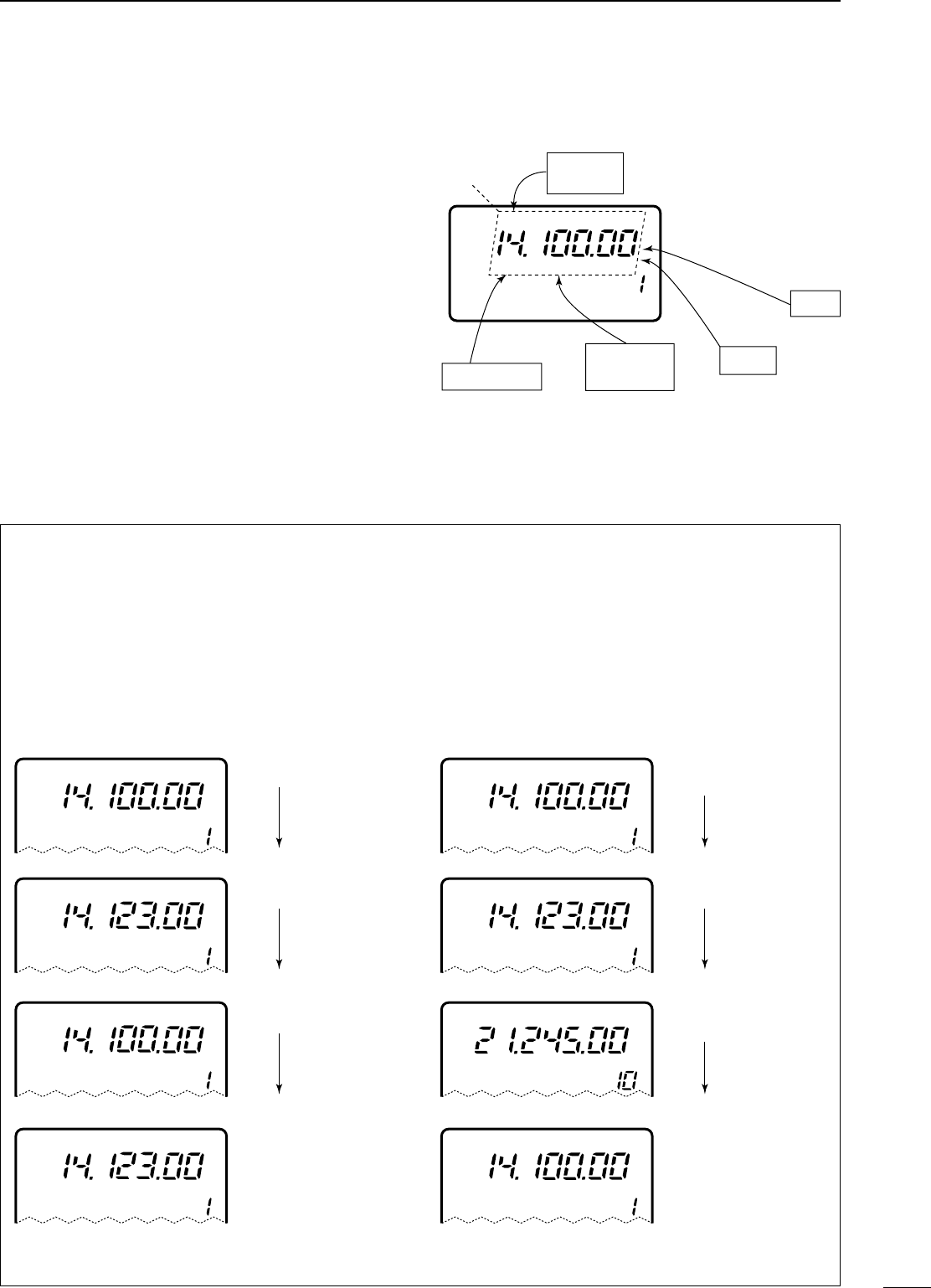
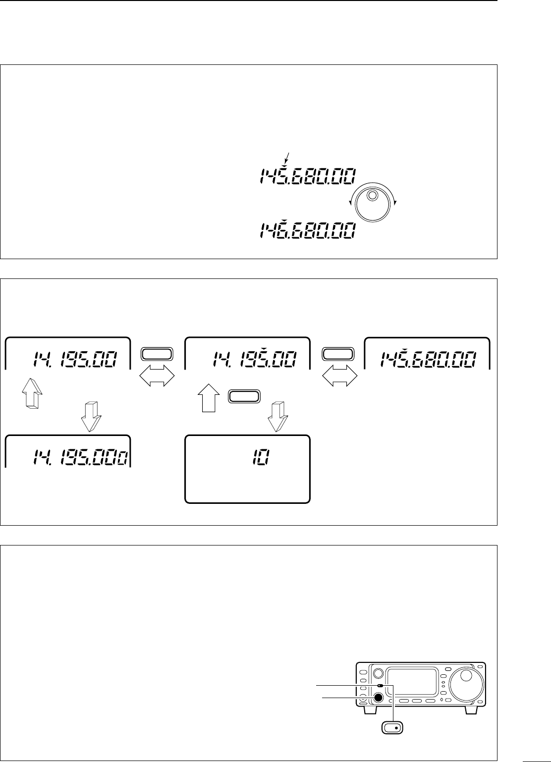
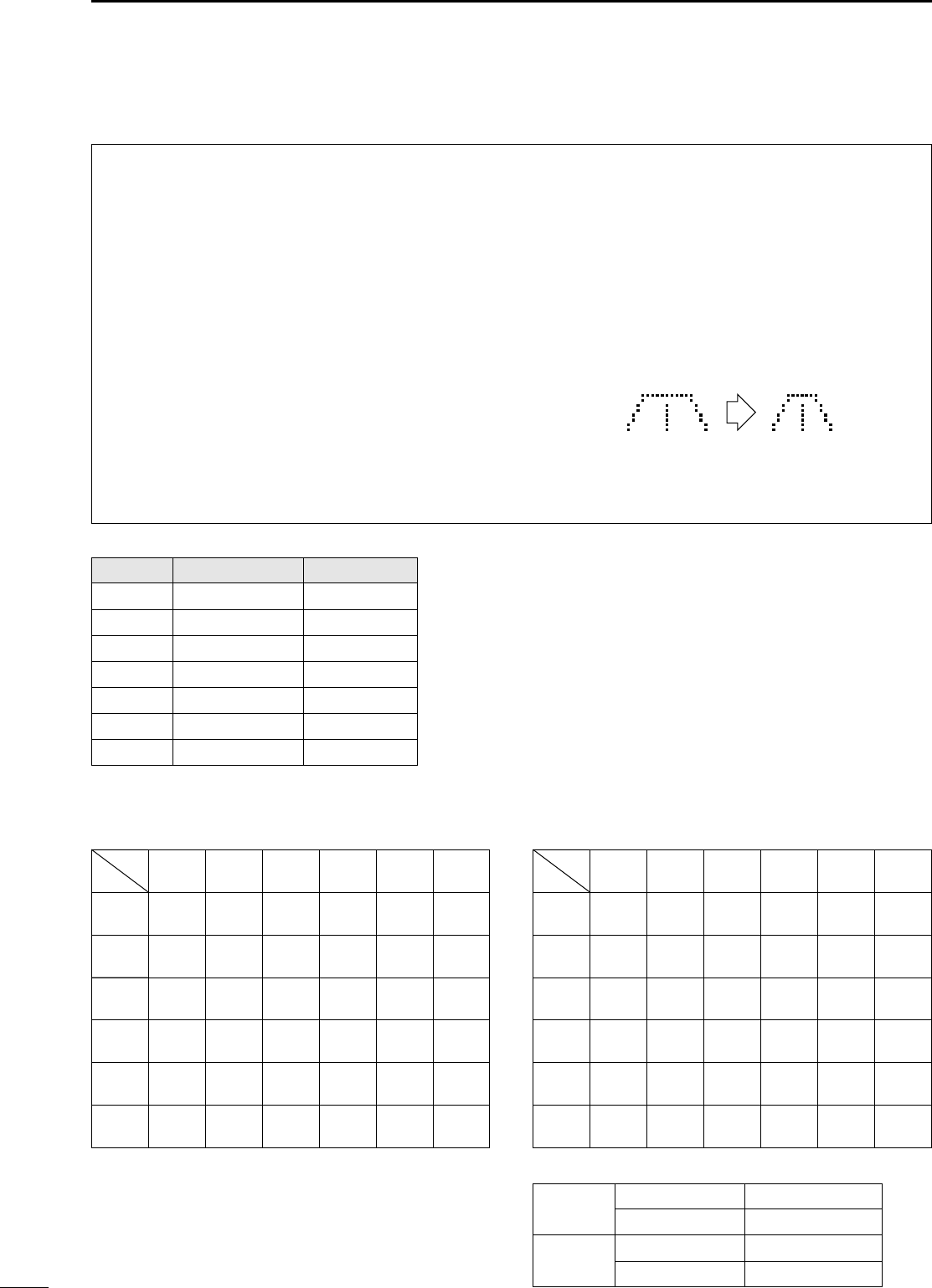
•TThhee ddiiffffeerreenncceess bbeettwweeeenn VVFFOO aanndd mmeemmoorryy mmooddee
VVFFOO MMOODDEE
Each VFO shows a frequency and operating mode. If
the frequency or operating mode is changed, the
VFO automatically memorizes the new frequency or
operating mode.
When the VFO is selected from another VFO or
memory mode, the last-used frequency and operat-
ing mode for that VFO appear.
[[EEXXAAMMPPLLEE]]
MMEEMMOORRYY MMOODDEE (pgs. 39–42)
Each memory channel shows a frequency and oper-
ating mode like a VFO. Even if the frequency or
mode is changed, the memory channel does not
memorize the new frequency or memory mode.
When a memory channel is selected from another
memory channel or VFO mode, the memorized fre-
quency and operating mode appear.
[[EEXXAAMMPPLLEE]]
CH
VFO A
USB
CH
VFO A
USB
VFO is selected.
The frequency is changed.
MEMO
CH
VFO A
USB VFO is selected again.
Changed frequency (14.123 MHz) appears. Changed frequency (14.123 MHz) does not appear and
memorised frequency (14.100 MHz) appears instead.
CH
USB Memory mode is selected.
CH
USB
CH
USB
Memory channel 1 is
selected.
The frequency is changed.
MEMO
MEMO
MEMO
MEMO
CH
USB Memory channel 1 is
selected again.
CH
USB Another memory channel
is selected.
IC-706MKIIG.qxd 02.3.27 13:53 Page 16
17
3FREQUENCY SETTING
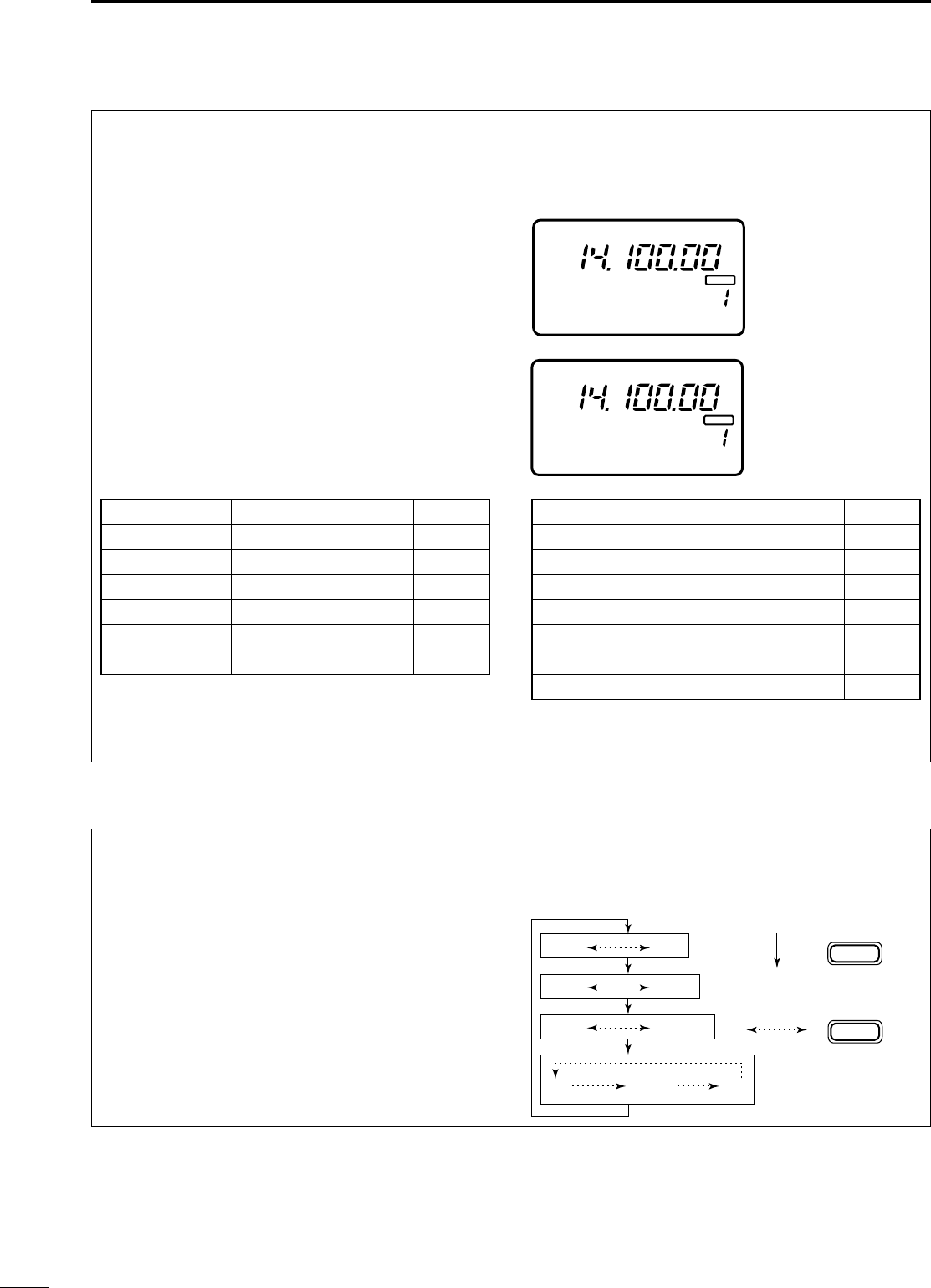
•PPrrooggrraammmmaabbllee ttuunniinngg sstteeppss
Programmable tuning steps are available to suit your
operating requirements.
These tuning steps are:
•Independently selectable for each mode
•Selectable from 0.01 (FM/WFM/AM only), 0.1, 1, 5,
9, 10, 12.5, 15, 20 and 100 kHz
➀Push [TS] one or more times until the programma-
ble tuning step indicator, “
Z
,” appears above the
1 kHz digit.
•Rotating the main dial changes the frequency accord-
ing to the set tuning step.
➁Push [TS] for 2 sec. while the programmable tun-
ing step indicator appears to enter the tuning step
selection mode.
•Rotate DIAL appears.
➂Rotate the main dial to set the desired tuning step.
•Change the mode and select tuning steps for other
modes, if desired.
➃Push [TS] to exit the tuning step selection mode.
➄Rotate the main dial to change the frequency
according to the set tuning step.
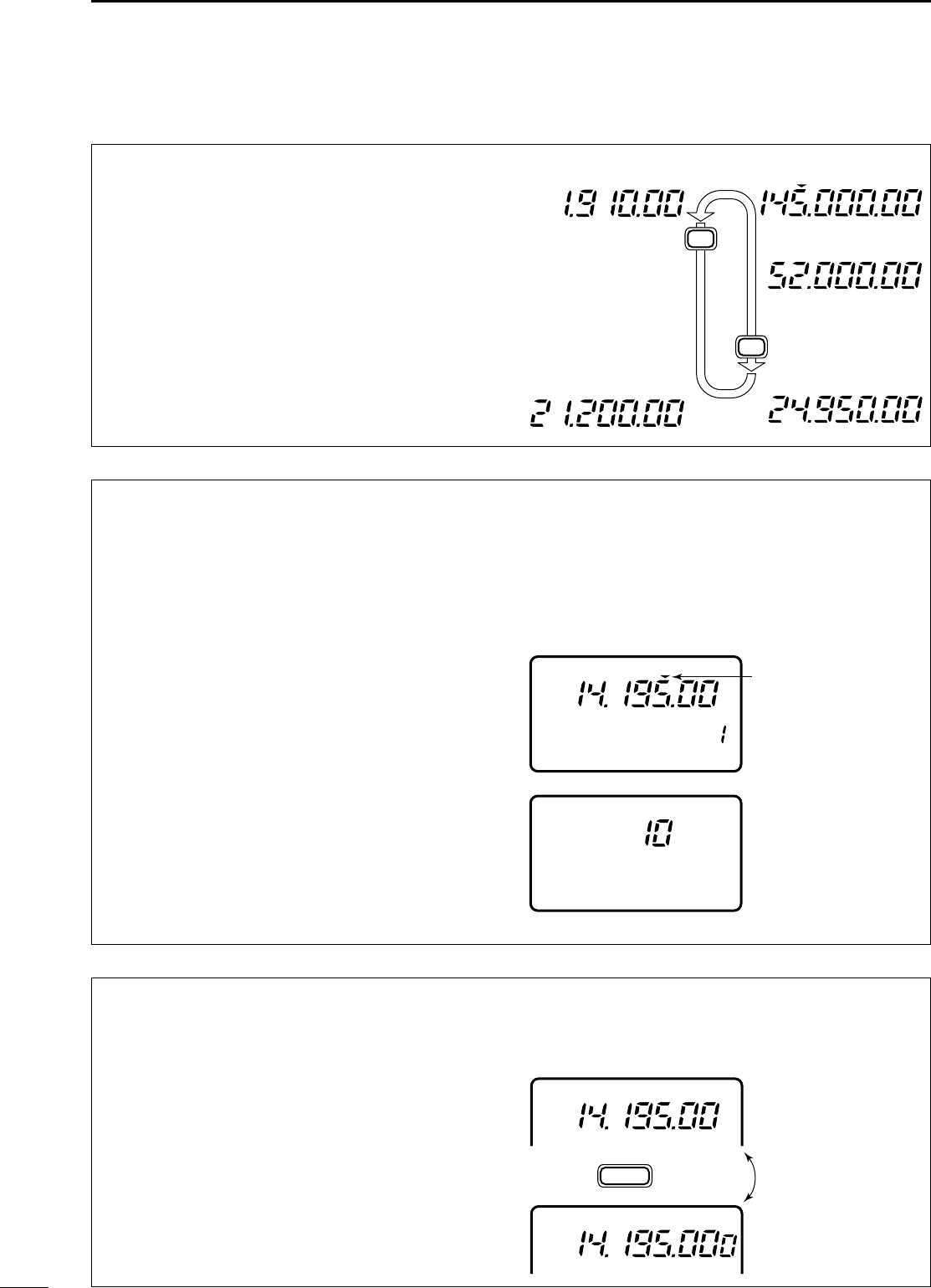
•BBaanndd sseelleeccttiioonn
All HF ham bands, the 50 MHz band, the 144 MHz
band and a general coverage receiver band are
included in the IC-706MKIIG.
Push [(Y)BAND]/[(Z)BAND] to select the desired
band.
•Pushing [(Y)BAND]/[(Z)BAND] continuously scrolls
through the available bands.
NNoottee::The band stacking register can also be used to
select bands. Refer to p. 19.
USB
FM
USB
USB
LSB
Z
Z
■FFrreeqquueennccyy sseettttiinngg
Programmable tuning
step indicator
10 kHz tuning step is
selected for USB
operation.
CH
VFO A
PO
S1
5
53792040
10
60dB
USB
USB
M1 A/B A=B
DIAL
SPL
Rotate
•11 HHzz aanndd 1100 HHzz ttuunniinngg sstteeppss
When neither the quick tuning step or programmable
tuning step, “
Z
,” appear, rotating the main dial
changes the frequency in increments of 1 or 10 Hz.
These tuning steps are only available in SSB, CW
and RTTY modes.
➀Select SSB, CW or RTTY mode if necessary.
➁Push [TS] for 2 sec. to toggle between the 1 and
10 Hz step settings.
•When the 1 Hz step is selected, the 1 Hz digit appears
in the frequency indication; when the 10 Hz step is
selected, the 1 Hz digit disappears from the frequency
indication.
Rotating the main dial
changes the frequency
in 10 Hz steps.
Rotating the main dial
changes the frequency
in 1 Hz steps.
TS
Push for 2 sec.
VFO A
USB
VFO A
USB
IC-706MKIIG.qxd 02.3.27 13:53 Page 17
18
3
FREQUENCY SETTING
•11 MMHHzz qquuiicckk ttuunniinngg sstteepp
The quick tuning step function allows you to change
the frequency in 1 MHz steps when rotating the main
dial. This function is only available in FM, WFM and
AM modes.
➀Select FM, WFM or AM mode if necessary.
➁Push [TS] momentarily to toggle between the 1
MHz tuning step and the programmable tuning
step.
•“
Z
” appears above the 1 MHz indicator when the 1 MHz
tuning step is selected.
•When the 1 MHz tuning step is selected, slow rotation
of the main dial changes the frequency in 1 MHz steps
and fast rotation of the main dial changes the frequen-
cy in 5 MHz steps.
Quick tuning step
indicator
Rotating the main dial
changes the frequen-
cy in 1 MHz steps.
FM
FM
[TS] SWITCH FLOW CHART
SSB/CW/RTTY modes Any mode FM/WFM/AM modes
TS
USB
10 Hz tuning
USB
1 Hz tuning
momentarily momentarily
momentarily
2 sec.2 sec.
2 sec.
TS
TS
1 MHz tuning
USB
Programmable step tuning
(100 Hz –100 kHz)
Selectable for each mode.
USB
Rotate DIAL
FM
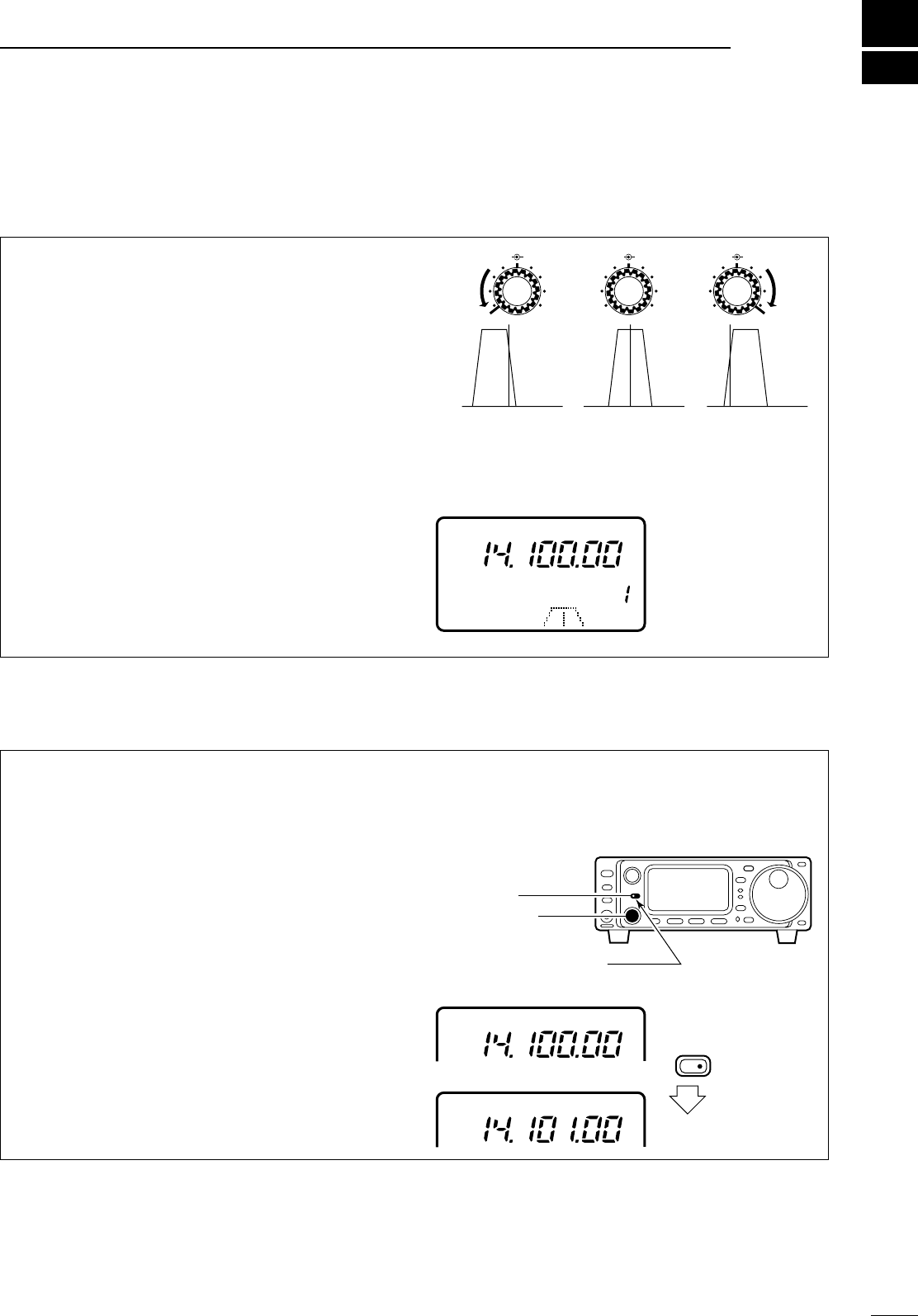
•SSuubb ddiiaall ffuunnccttiioonn
The sub dial function allows you to change the oper-
ating frequency using the [M-CH] control. This gives
you more control in tuning since the [M-CH] knob is
detented—each click changes the frequency
according to the set tuning step. This function is
always available in FM, WFM and AM modes.
However, in SSB, CW and RTTY modes, the set
mode item “Sub dial function,” must be set to “FrEq.”
➀Push [RIT/SUB] to turn the sub dial function ON.
•The [SUB] indicator lights green; if it lights red, the RIT
function is activated—sub dial function must be set in
initial set mode in this case.
➁Rotate [M-CH] to change the operating frequency
according to the set tuning steps.
➂Push [RIT/SUB] again to turn the function OFF.
•The [SUB] indicator turns off.
[SUB] switch
Indicator lights green
while the sub dial function
is activated.
[M-CH] control
RIT/
SUB
IC-706MKIIG.qxd 02.3.27 13:53 Page 18
19
3FREQUENCY SETTING
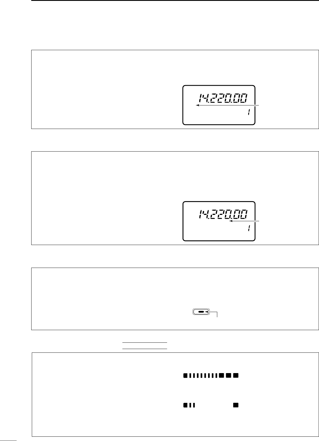
•QQuuiicckk bbaanndd cchhaannggee ffuunnccttiioonn
The quick band change function automatically stores
the last frequency and mode used for each band in a
band stacking register. This is convenient for contest
operation, etc. The tables below show the quick
band change default settings for each band.
➀Select S3.
•Push [DISPLAY] when M or G is displayed.
•Push [MENU] twice to select S3.
➁Push [F-1]–[F-3] to select a band stacking register.
•The default settings for [F-1]–[F-3] are 7, 144 and 430
MHz bands, respectively.
➂To change the settings for [F-1]–[F-3] from their
defaults, push [F-1]–[F-3] for 1 sec. one or more
times to until the desired band appears in the dis-
play above the corresponding switch.
•The last-used frequency and mode for the selected
band are displayed.
*General refers to the general coverage receiver (GEN in
the display) and the range varies according to version.
** 1.83000 MHz for Italy version (#10,#20).
■MMooddee sseelleeccttiioonn
The following modes are available in the IC-
706MKIIG:
SSB (LSB/USB), CW, CW-å(CW reverse), FM, WFM
(receive only), AM, RTTY and åRTTY (RTTY
reverse).
To select the desired mode of operation push
[MODE] one or more times, then push [MODE] for 2
sec., if necessary. See the diagram at right for the
order of selection.
•The selected mode is indicated in the function display.
NNoottee::If a desired mode cannot be selected, it may be
hidden using Initial Set mode (p. 50).
OPERATING MODE SELECTION
MODE
Push
momentarily
MODE
Push
for 2 sec.
USB LSB
CW CWå
RTTY åRTTY
FM WFM AM
BBAANNDDFFRREEQQUUEENNCCYYMMOODDEE
18 MHz 18.15000 MHz USB
21 MHz 21.30000 MHz USB
24 MHz 24.95000 MHz USB
28 MHz 28.60000 MHz USB
50 MHz 50.10000 MHz USB
144 MHz 145.00000 MHz FM
BBAANNDDFFRREEQQUUEENNCCYYMMOODDEE
1.9 MHz 1.91000 MHz** CW
3.5 MHz 3.56000 MHz LSB
7 MHz 7.06000 MHz LSB
10 MHz 10.13000 MHz CW
14 MHz 14.10000 MHz USB
General* 15.10000 MHz USB
BLANK
CH
VFO A
S1 5379204060dB
USB
S3 7144 430
Display shows the
default bands for the
quick band change
function.
PO510
BLANK
CH
VFO A
S1 5379204060dB
USB
S3 7GEN 144
Display shows [F-2]
has been changed from
its default of the 50 MHz
band to the general
receiver band.
PO510
430 MHz 433.00000 MHz FM
IC-706MKIIG.qxd 02.3.27 13:53 Page 19
20
4
RREECCEEIIVVEE AANNDD TTRRAANNSSMMIITT
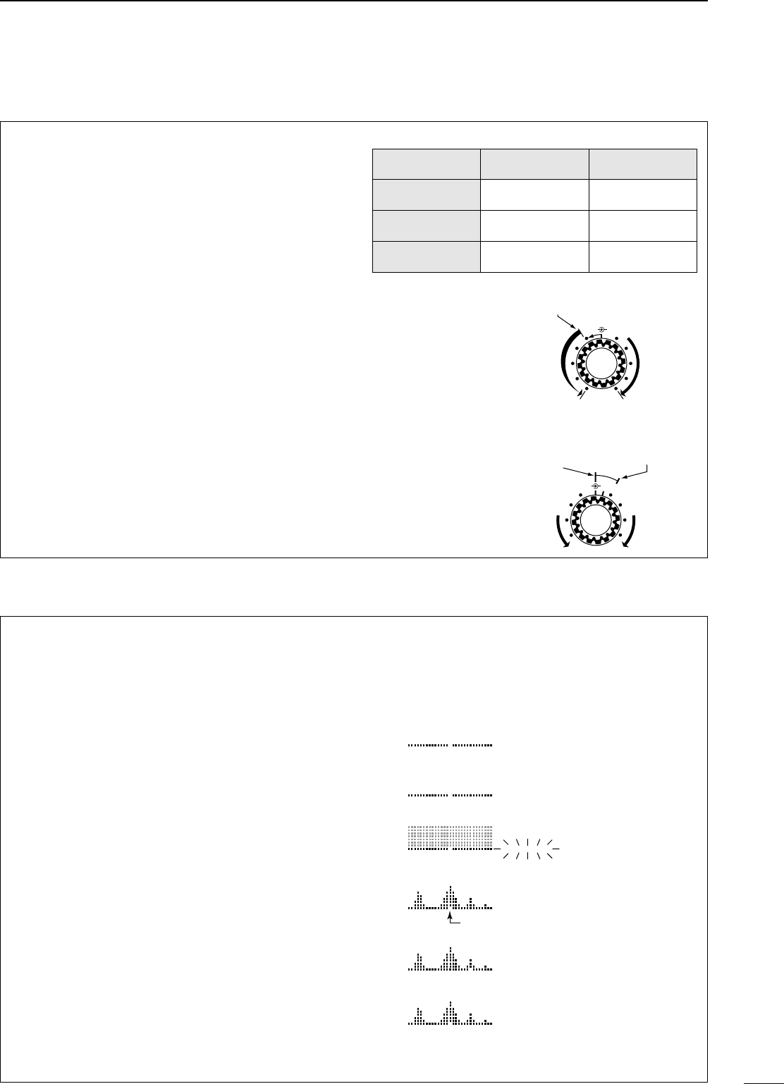
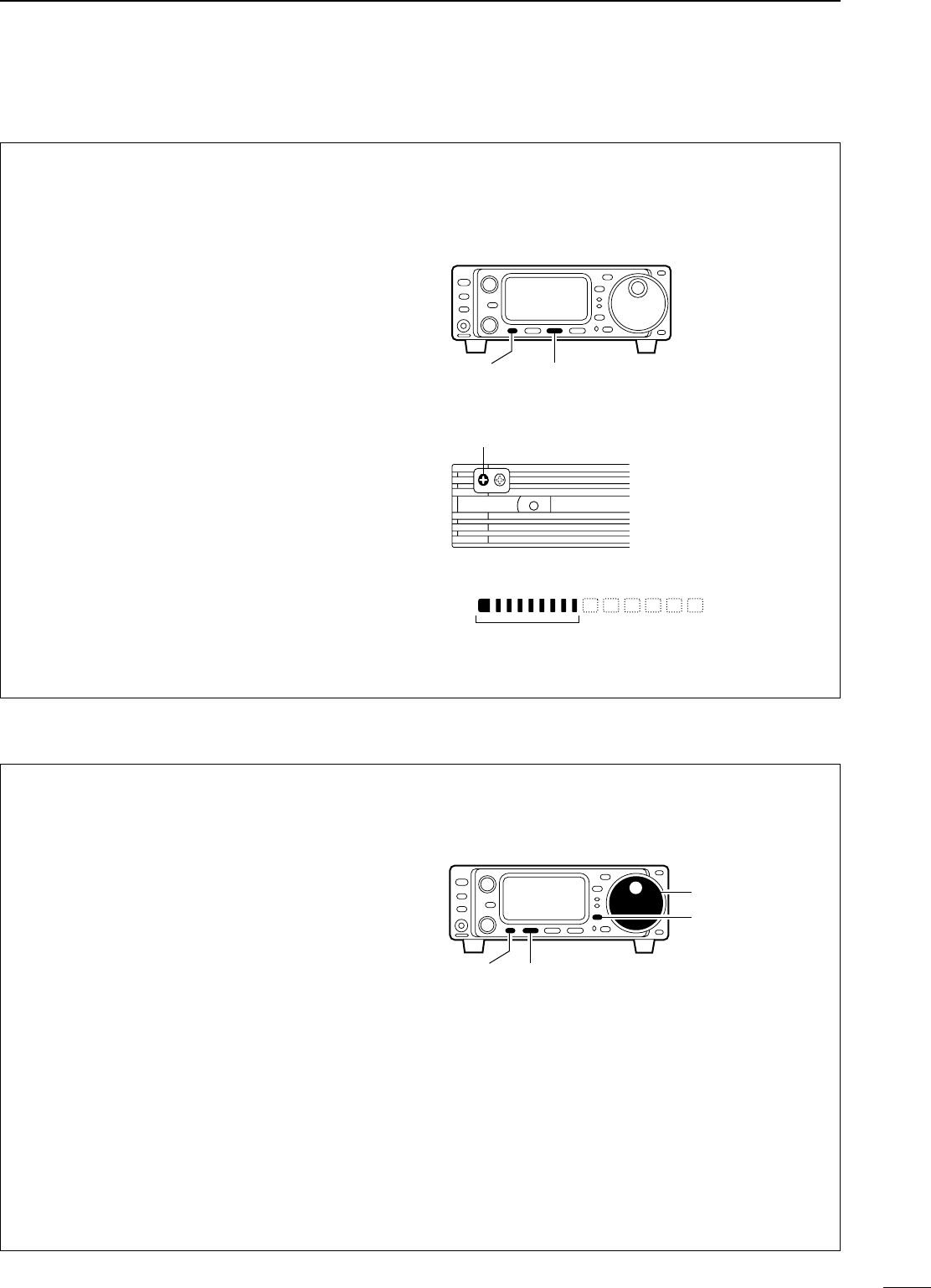
The IF shift function electronically changes the pass-
band frequency of the IF (intermediate frequency)
and cuts out higher or lower frequency components
of the IF to reject interference. The function shifts the
IF frequency up to ±1.2 kHz in 15 Hz steps in
SSB/CW/RTTY modes and up to ±250 Hz in 3 Hz
steps in CW-ã/RTTY-ãmodes. The IF shift is not
available in FM and AM modes.
➀Adjust the [SHIFT] control for a minimum interfer-
ence signal level.
•The audio tone may be changed while the IF shift is in
use.
➁Set the shift control to its center position when
there is no interference.
•GGrraapphhiicc ddiissppllaayy
The IF shift is displayed graphically (for about 1 sec.)
each time the shift control is rotated.
M-CH M-CH M-CHSHIFT SHIFT SHIFT
Shifts low Center Shifts high
DRRIITT ffuunnccttiioonn
The RIT (Receive Incremental Tuning) function com-
pensates for off-frequencies of communicating sta-
tions. The function shifts the receive frequency up to
±9.99 kHz in 10 Hz steps without moving the transmit
frequency. The [SUB/RIT] switch in Initial Set Mode
must be set to RIT mode in advance (p. 51).
➀Push [RIT].
•The [RIT] indicator lights red.
➁Rotate the [M-CH] control to cancel the off-fre-
quencies.
•The transmit frequency is not shifted.
➂To cancel the RIT function, push [RIT] again.
•The [RIT] switch indicator goes out.
•CCaallccuullaattee ffuunnccttiioonn
The shift frequency of the RIT function can be
added/subtracted to the displayed frequency.
While the RIT indicator is lit, push and hold [RIT] for
2 sec.
NNoottee::The RIT function is not available in FM, WFM or
AM modes regardless of the Initial Set mode setting
(p. 51).
[RIT] switch
Indicator lights red while
RIT function is activated.
Push for
2 sec.
[M-CH] control
USB
USB
CH
VFO A
S1 5379204060dB
USB
DIIFF sshhiifftt ffuunnccttiioonn
■FFuunnccttiioonnss ffoorr rreecceeiivvee
IC-706MKIIG.qxd 02.3.27 13:53 Page 20
21
4RECEIVE AND TRANSMIT
DNNooiissee bbllaannkkeerr
The noise blanker reduces pulse-type noise such as
that generated by automobile ignition systems. This
function is not effective for FM modes or for non
pulse-type noise. If you don’t want to use the noise
blanker for AM communications, the “AM noise
blanker” item in Initial Set mode must be turned OFF
(ON is the default setting—p. 53).
➀Select M3.
•Push [DISPLAY] 1 or 2 times when Sor Gis displayed,
until Mis displayed.
•Push [MENU] one or more times to select M3.
➁Push [(F-2)NB] to toggle the noise blanker ON and
OFF.
•“NB” appears when the noise blanker is turned ON.
NB
CH
VFO A
S1 5379204060dB
USB
M3 NAR NB MET
Appears when the
noise blanker is
turned ON.
PO510
DAAGGCC ttiimmee ccoonnssttaanntt
The AGC (Automatic Gain Control) controls receiver
gain to produce a constant audio output level even
when the received signal strength is varied by fading,
etc. Use AGC slow for normal phone operation; AGC
fast for receiving data and searching for signals. AGC
time constant cannot be changed in FM mode.
➀Select M4.
•Push [DISPLAY] 1 or 2 times when Sor Gis displayed.
•Push [MENU] one or more times to select M4.
➁Push [(F-3)AGC] to toggle the AGC time constant
between fast and slow.
•“FAGC” appears when the fast time constant is selected.
CH
VFO A
S1 5379204060dB
USB
M4 VOX COM AGC
Appears when
AGC fast is
selected.
FAGC
PO510
DPPrreeaammpp aanndd aatttteennuuaattoorr
The preamp amplifies received signals in the front
end circuit to improve the S/N ratio and sensitivity.
Turn this function ON when receiving weak signals.
The attenuator prevents desired signals from distort-
ing when very strong signals are near the desired fre-
quency or when very strong electric fields, such as
from broadcasting stations, are near your location.
Push [P.AMP/ATT] momentarily to turn the preamp
ON and OFF; push and hold to turn the attenuator ON.
•Lights green when the preamp is ON; lights red when
the 20 dB attenuator is ON.
•Only one of these functions can be activated at a time.
P.AMP/ATT
Lights green while the preamp is activated;
lights red while the attenuator is activated.
DPPeeaakk mmeetteerr hhoolldd
The peak meter hold function freezes the highest
displayed bar segment in any meter function for
about 0.5 sec. so that you can more easily read the
meter. This function can be turned ON and OFF in ini-
tial set mode (see p. 51).
INITIAL SET MODE
S1 5379204060dB
S1 5379204060dB
Initial reception of a
signal results in an S-
meter reading of 40
dB.
The highest indicated
bar remains displayed
for about 0.5 sec.
even when the signal
strength decreases.
[EXAMPLE]:
IC-706MKIIG.qxd 02.3.27 13:53 Page 21
22
4
RECEIVE AND TRANSMIT
DRRFF ggaaiinn aanndd ssqquueellcchh
DSSiimmppllee bbaanndd ssccooppee
The IC-706MKIIG uses the same control, [RF/SQL],
to adjust one of either the RF gain or the squelch.
[RF/SQL] adjusts either the RF gain or the squelch
depending on the operating mode selected and the
condition of the RF gain item in initial set mode (p. 51;
also see the table at right).
The RF (Radio Frequency) gain is used to adjust the
receiver gain.
•This control should be set to the 11 o’clock position for
normal use.
•Shallow rotation moves the S-meter to the right indicating
the signal strength which can be received.
The SQUELCH removes noise output from the
speaker (closed condition) when no signal is
received. The squelch is particularly effective for FM.
It is also available for the other modes.
•When operating in FM, first rotate the control fully coun-
terclockwise. Then, rotate the control clockwise to the
point where the noise just disappears. This is the best
position. The squelch does not open for weak signals
when it is set too deep.
•A segment appears in the S-meter to indicate the S-meter
squelch level.
••[[RRFF//SSQQLL]] ccoonnttrrooll pprriioorriittyy
AF RF/SQL
Max. RF gain position
RF gain
decreases
Same effect as at
the center position
AF RF/SQL
Deep
Squelch
opens
S-meter squelch
threshold point
Noise squelch
threshold point
This function allows you to visually “sweep” an area
surrounding the set frequency for other signals.
Detected signals are indicated graphically in the dot
matrix section of the display.
➀Set a mode and frequency.
➁Select G1.
•Push [DISPLAY] 1 or 2 times if Mor Sappears.
•Push [MENU] one or more times to select G1.
➂Push [F-1] one or more times to select the desired
steps.
•Each dot corresponds to a step for the indicated fre-
quency.
•0.5, 1, 2, 5, 10, 20 and 100 kHz can be set for the scope
step.
➃Push [F-3] to start the sweep.
•“___” (below SWP) flashes while sweeping.
•The receive audio is muted while sweeping.
➄Rotate the main dial if you want to monitor the dis-
played signals.
•The sweep marker indicates the location of the dis-
played frequency in the sweep readout.
•If the displayed frequency is outside of the sweep read-
out (determined by the sweep width), the sweep marker
flashes.
➅Push [F-2] to return the frequency to the start of a
sweep.
•The sweep marker moves back to the center position.
1k SWP
2k SWP
2k SWP
2k SWP
___
2k SWP
Select sweep width
([F-1])
Start sweep
([F-3])
Sweep is finished
([F-3] again)
Move sweep marker
(main dial)
2k SWP Returns to previous
frequency ([F-2])
sweep marker
NNoottee::The recommended
position for RF gain is the
11 o’clock position since
this sets RF gain to the
max.
When set to AUTO, SQL is
active in FM/WFM/AM; RF
is active in SSB/CW/RTTY.
NNoottee::Use the attenuator or turn OFF the preamp when
using the band scope on a band containing a lot of noise.
Initial set mode
setting
USB, LSB,
CW, RTTY AM, FM, WFM
SQL*1SQL SQL
AUTO RF GAIN SQL
RF •SQL*2RF/SQL RF/SQL
*1Default; *2Default for USA version.
IC-706MKIIG.qxd 02.3.27 13:53 Page 22
FFiilltteerr vvaarriiaattiioonnss
*Optional filter.
OOppttiioonnaall ffiilltteerr iinnssttaallllaattiioonn aanndd sseelleeccttiioonn ttaabblleess
SSSSBB
23
4RECEIVE AND TRANSMIT
DOOppttiioonnaall ffiilltteerr sseelleeccttiioonn
Two optional filters can be installed in the IC-
706MKIIG.
Narrow filters help reject interference from adjacent
signals and obtain good selectivity.
Wide filters provide improved audio for SSB opera-
tion when no interfering signals are present.
Consult the table below to select a filter most suitable
for your operating needs.
Narrow filters for AM/FM modes are standard.
FFIILLTTEERR PPRREESSEETTTTIINNGG::
After you install a filter (see p. 60 for installation), you
must specify the installed filter in initial set mode (item
19 “OPT. FIL 1” or item 20 “OPT. FIL 2”; see p. 51).
FFIILLTTEERR OONN//OOFFFF::
➀Select M3.
•Push [DISPLAY] 1 or 2 times if Gor Sappears.
•Push [MENU] one or more times to select M3.
➁Push [(F-1)FIL] momentarily to select the narrow
filter; for 2 sec. to select the wide filter.
•ãappears when the narrow filter is selected; ç
appears when the wide filter is selected.
NNoottee::When selecting the narrow filter, the graphic
passband is narrowed (see diagram below).
Normal
operation
narrow is
selected
FL-101* CW, RTTY 250 Hz/–6 dB
CW, RTTY 350 Hz/–6 dB
CW, RTTY 500 Hz/–6 dB
SSB, CW, RTTY 2.8 kHz/–6 dB
FL-223* SSB, CW, RTTY 1.9 kHz/–6 dB
SSB, CW, RTTY 2.4 kHz/–6 dB
AM, FM 8 kHz/–6 dB
MMooddeeBBaanndd wwiiddtthhNNaammee
FFIILL 11
FFIILL 22
NNoo
ooppttiioonnaall
ffiilltteerr
FFLL--110000FFLL--110011FFLL--110033FFLL--222233FFLL--223322
NNoo
ooppttiioonnaall
ffiilltteerr
W:–––
M:FL-272
N: –––
W:–––
M:FL-272
N: –––
W:–––
M:FL-272
N: –––
W:FL-103
M:FL-272
N: –––
W:–––
M:FL-272
N: FL-223
W:–––
M:FL-272
N: –––
FFLL--110000
W:–––
M:FL-272
N: –––
W:–––
M:FL-272
N: –––
W:–––
M:FL-272
N: –––
W:FL-103
M:FL-272
N: –––
W:–––
M:FL-272
N: FL-223
W:–––
M:FL-272
N: –––
FFLL--110011
W:–––
M:FL-272
N: –––
W:–––
M:FL-272
N: –––
W:–––
M:FL-272
N: –––
W:FL-103
M:FL-272
N: –––
W:–––
M:FL-272
N: FL-223
W:–––
M:FL-272
N: –––
FFLL--110033
W: FL-103
M:FL-272
N: –––
W: FL-103
M:FL-272
N: –––
W: FL-103
M:FL-272
N: –––
W: FL-103
M:FL-272
N: –––
W: FL-103
M:FL-272
N: FL-223
W: FL-103
M:FL-272
N: –––
FFLL--222233
W:–––
M:FL-272
N: FL-223
W:–––
M:FL-272
N: FL-223
W:–––
M:FL-272
N: FL-223
W:FL-103
M:FL-272
N: FL-223
W:–––
M:FL-272
N: FL-223
W:–––
M:FL-272
N: FL-223
FFLL--223322
W:–––
M:FL-272
N: –––
W:–––
M:FL-272
N: –––
W:–––
M:FL-272
N: –––
W: FL-103
M:FL-272
N: –––
W:–––
M:FL-272
N: FL-223
W:–––
M:FL-272
N: –––
FFIILL11
FFIILL 22
NNoo
ooppttiioonnaall
ffiilltteerr
FFLL--110000FFLL--110011FFLL--110033FFLL--222233FFLL--223322
NNoo
ooppttiioonnaall
ffiilltteerr
W:–––
M:FL-272
N: –––
W:–––
M:FL-272
N: FL-100
W:–––
M:FL-272
N: FL-101
W:FL-103
M:FL-272
N: –––
W:–––
M:FL-272
N: FL-223
W:–––
M:FL-272
N: FL-232
FFLL--110000
W:–––
M:FL-272
N: FL-100
W:–––
M:FL-272
N: FL-100
W: FL-272
M:FL-100
N: FL-101
W:FL-103
M:FL-272
N: FL-100
W:FL-272
M:FL-223
N: FL-100
W:FL-272
M:FL-100
N: FL-232
FFLL--110011
W:–––
M:FL-272
N: FL-101
W: FL-272
M:FL-100
N: FL-101
W:–––
M:FL-272
N: FL-101
W:FL-103
M:FL-272
N: FL-101
W: FL-272
M:FL-223
N: FL-101
W:FL-272
M:FL-232
N: FL-101
FFLL--110033
W: FL-103
M:FL-272
N: –––
W: FL-103
M:FL-272
N: FL-100
W: FL-103
M:FL-272
N: FL-101
W: FL-103
M:FL-272
N: –––
W: FL-103
M:FL-272
N: FL-223
W: FL-103
M:FL-272
N: FL-223
FFLL--222233
W:–––
M:FL-272
N: FL-223
W:FL-272
M:FL-223
N: FL-100
W:FL-272
M:FL-223
N: FL-101
W:FL-103
M:FL-272
N: FL-223
W:–––
M:FL-272
N: FL-223
W:FL-272
M:FL-223
N: FL-232
FFLL--223322
W:–––
M:FL-272
N: FL-232
W: FL-272
M:FL-100
N: FL-232
W: FL-272
M:FL-232
N: FL-101
W: FL-103
M:FL-272
N: FL-232
W: FL-272
M:FL-223
N: FL-232
W:–––
M:FL-272
N: FL-232
FL-100*
FL-232*
FL-94
FL-103*
FL-272
FM Normal FL-23 +SFPC455E
Narrow FL-94
AM Normal FL-94
Narrow FL-272
CCWW,, RRTTTTYY
Table key:
W—wide position
M—medium (normal) position
N—Narrow position
IC-706MKIIG.qxd 02.3.27 13:53 Page 23
24
4
RECEIVE AND TRANSMIT
This function automatically attenuates beat tones,
tuning signals, etc., even if they are moving. The
automatic notch filter functions in SSB, FM and AM
modes.
➀Select S4 (DSP menu).
•Push [DISPLAY] 1 or 2 times when Mor Gis displayed.
•Push [MENU] one or more times to select S4.
➁Push [(F-1)ANF] to toggle the automatic notch fil-
ter ON and OFF.
•“DSP” and “ANF” appear when the function is ON.
DNNRR ((NNooiissee RReedduuccttiioonn)) ffuunnccttiioonn
This function reduces noise components and picks
out desired signals which are buried in noise. The
received AF signals are converted to digital signals
and then the desired signals are separated from the
noise. The noise reduction function is available for all
operating modes.
➀Select S4 (DSP menu).
•Push [DISPLAY] 1 or 2 times when Mor Gis displayed.
•Push [MENU] one or more times to select S4.
➁Push [(F-2)NR] to toggle the noise reduction func-
tion ON and OFF.
•“DSP” and “NR” appear when the function is ON.
➂Push [(F-3)NRL] to toggle the noise reduction
level indication ON and OFF.
➃Rotate the [M-CH] control to set the noise reduc-
tion level.
•Set the control for maximum readability. Deep rotation
results in audio signal masking or distortion.
☞NNOOTTEE::Pushing [(F-3)NRL] automatically turns the
noise reduction function ON, however, the trans-
ceiver maintains the ON/OFF condition when
pushing [(F-2)NR].
DAANNFF ((AAuuttoommaattiicc NNoottcchh FFiilltteerr)) ffuunnccttiioonn
■DDSSPP FFuunnccttiioonnss (may require an optional unit depending on version—see p. 61)
DSP
CH
VFO A
P
O
S1
5
5379204060dB
USB
BLANK
ANF
S4 ANF NR NRL
DSP
CH
VFO A
P
O
S1
5
5379204060dB
USB
BLANK
NR
S4 ANF NR NRL
S4 LEVEL 8 NRL
IC-706MKIIG.qxd 02.3.27 13:53 Page 24
25
4RECEIVE AND TRANSMIT
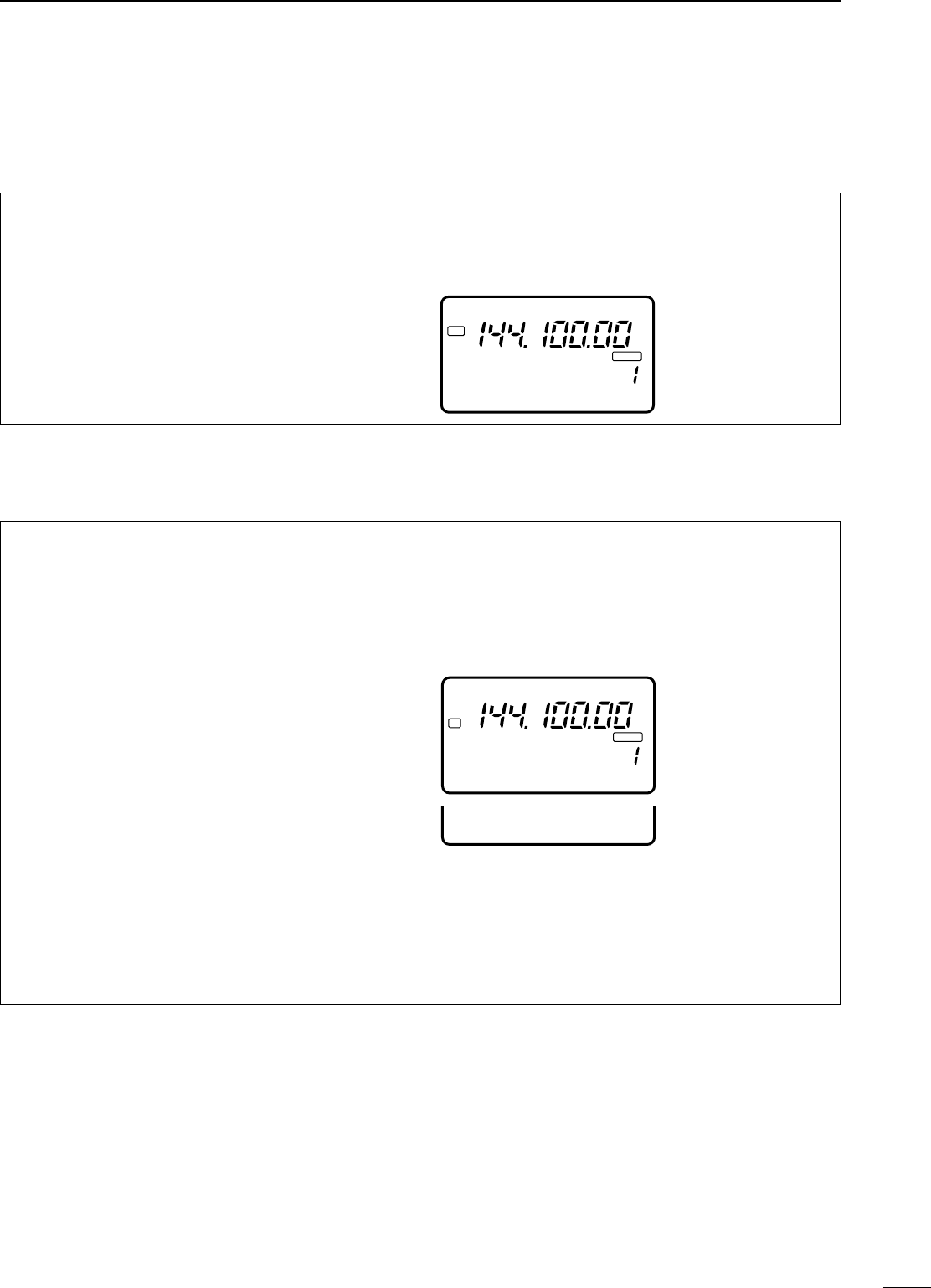
•SSeettttiinngg oouuttppuutt ppoowweerr
➀
Push [DISPLAY] for 2 sec. to select quick set mode.
➁Push [MENU] one or more times to select Q1 RF
POWER.
➂Rotate the main dial to select the desired output.
•Output power is displayed in 11 steps (L, 1–9 and H) but
is continuously selectable.
➃Push [DISPLAY] to exit quick set mode.
•AAvvaaiillaabbllee ppoowweerr
*Carrier power
•SSeettttiinngg mmiiccrroopphhoonnee ggaaiinn
Microphone gain must be adjusted properly so that
your signal does not distort when transmitted.
➀Select SSB or another phone mode.
➁
Push [DISPLAY] for 2 sec. to select quick set mode.
➂Push [MENU] one or more times to select Q2 MIC
GAIN.
•The ALC meter is selected automatically when operat-
ing in SSB mode.
➃While speaking into the microphone adjust the mic
gain so that the ALC meter does not peak past the
ALC zone.
➄Push [DISPLAY] to exit quick set mode.
USB
Q1 RF POWER
Maximum output power is
selected.
PO
S1
5
53792040
10
60dB
Microphone gain is
set to 6.
ALC
S1
123
5379204060dB
USB
Q2 MIC GAIN
ALC
ALC zone
DMMeetteerr ffuunnccttiioonn
The bar meter in the function display acts as an
S-meter (for relative signal strength, except in WFM
mode) during receive and can be selected for one of
three types during transmit.
➀Select M3.
•Push [DISPLAY] 1 or 2 times when Sor Gappears.
•Push [MENU] one or more times to select M3.
➁Push [(F-3)MET] one or more times to select the
desired meter function.
•The display indication changes as in the table at right.
DOOuuttppuutt ppoowweerr aanndd mmiicc ggaaiinn
■FFuunnccttiioonnss ffoorr ttrraannssmmiitt
NNoottee::The SWR meter cannot be used for the 144/430 MHz
bands since the meter activates for the [ANT 1] connector
only.
BBAANNDDSSSSBB//CCWW//RRTTTTYY//FFMMAAMM**
HF 5–100 W 4–40 W
50 MHz 5–100 W 4–40 W
144 MHz 2–20 W 2–8 W
DDIISSPPLLAAYY
IINNDDIICCAATTIIOONNMMEEAASSUURREEMMEENNTT
PPooIndicates the relative RF output power.
AALLCC
Indicates the ALC level. When the
meter movement shows the input signal
level exceeds the allowable level, the
ALC limits the RF power. In such cases,
reduce the microphone gain (see
above).
SSWWRRIndicates the SWR over the transmis-
sion line.
IC-706MKIIG.qxd 02.3.27 13:53 Page 25
26
4
RECEIVE AND TRANSMIT
DSSppeeeecchh ccoommpprreessssoorr
The IC-706MKIIG has a built-in, low distortion speech
compressor circuit. This circuit increases your aver-
age talk power in SSB mode and is especially useful
for DX’ing when the receiving station is having diffi-
culty copying your signal.
➀Select USB or LSB mode.
➁Select the ALC meter.
•Push [DISPLAY] 1 or 2 times to select M, if necessary.
•Push [MENU] one or more times to select M3, then
push [(F-3)MET] one or more times to select “ALC.”
➂Select the mic gain display in quick set mode.
•Push [DISPLAY] for 2 sec.
•Push [MENU] one or more times to select Q2 MIC
GAIN.
➃Adjust the mic gain.
•While transmitting at your normal voice level, the ALC
meter should read at about the middle of the ALC zone.
•Be sure the mic gain is in the range of 2 to 5.
➄Select M4.
•Push [DISPLAY] 1 or 2 times to select M, if necessary.
•Push [MENU] one or more times to select M4.
➅Push [(F-2)COM], then adjust [COMP GAIN] so that
the ALC meter reads within the ALC zone whether
you speak softly or loudly.
NNoottee::When the ALC meter peaks above the ALC
zone, your transmitted voice may be distorted.
[MENU] [(F-2)COM]
[COMP GAIN]
COMP
GAIN /SIDE T
BEEP
ALC
Adjust [COMP GAIN] so that the ALC meter
reads within the ALC zone.
ALC zone
DVVOOXX ooppeerraattiioonn
The VOX (Voice-operated Transmission) function
toggles between transmit and receive with your
voice. This function provides an opportunity to input
log entries into your computer, etc., while operating.
➀Select M4, then turn the VOX function ON.
•Push [DISPLAY] 1 or 2 times when Sor Gappears.
•Push [MENU] one or more times to select M4.
•Push [(F-1)VOX] to turn the function ON.
➁Select VOX GAIN in quick set mode.
•Push [DISPLAY] for 2 sec. then push [MENU] one or
more times to select Q4.
➂While speaking into the microphone, adjust [VOX
GAIN] until the transceiver is transmitting.
➃Select VOX DELAY in quick set mode.
•Push [MENU] one or more times to select Q3.
➄While speaking into the microphone, adjust [VOX
DELAY] as desired.
➅Select ANTI VOX in quick set mode.
•Push [MENU] one or more times to select Q5.
➆If the receive audio from the speaker toggles the
transceiver to transmit during receive, adjust the
[ANTI-VOX] to the point where it has no effect.
➇Push [DISPLAY] to exit quick set mode.
[MENU] [(F-1)VOX]
[DISPLAY]
main dial
IC-706MKIIG.qxd 02.3.27 13:53 Page 26
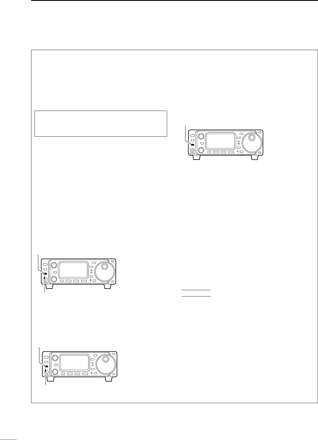
27
4RECEIVE AND TRANSMIT
The AT-180 automatic antenna tuner matches the IC-
706MKIIG to the connected antenna automatically.
Once the tuner matches an antenna, the variable
capacitor angles are memorized as a preset point for
each frequency range (100 kHz steps). Therefore,
when you change the frequency range, the variable
capacitors are automatically preset to the memorized
point.
NNoottee::
•The AT-180 cannot be used for the 144/430 MHz
band.
•When operating on the 144/430 MHz band, push-
ing the tuner switch selects the call channel (p. 39).
•The AT-180 can match both HF and 50 MHz bands.
However, operation is different for the HF and 50
MHz bands.
TTUUNNEERR OOPPEERRAATTIIOONN
•FFoorr tthhee HHFF bbaanndd::
Push [TUNER] to turn the tuner ON. The antenna is
tuned automatically during transmission when the
antenna SWR is higher than 1.5:1.
•When the tuner is OFF, the [TUNER] light goes out.
•FFoorr tthhee 5500 MMHHzz bbaanndd::
Push and hold [TUNER] to tune the antenna. If the
[TUNER] light flashes slowly while transmitting, push
and hold [TUNER] again to re-tune the antenna.
MMAANNUUAALL TTUUNNIINNGG
During SSB operation on HF bands at low voice lev-
els, the AT-180 may not be tuned correctly. In such
cases, manual tuning is helpful.
Push and hold [TUNER] for 1 sec. to start manual tun-
ing.
•CW mode is selected, a side tone is emitted, and the
[TUNER] light flashes; then, the previous mode is select-
ed.
If the tuner cannot reduce the SWR to less than 1.5:1
after 20 sec. of tuning, the [TUNER] light goes out. In
this case, check the following:
•the antenna connection and feedline
•the antenna SWR (p. 26; meter function)
TThhrroouugghh iinnhhiibbiitt (HF bands only)
The AT-180 has a through inhibit condition. When
selecting this condition, the tuner can be used at
poor SWR’s. In this case, automatic tuning in the HF
bands activates only when exceeding SWR 3:1.
Therefore, manual tuning is necessary each time you
change the frequency. Although termed “through
inhibit,” the tuner will be “through” if the SWR is high-
er than 3:1 after tuning.
•TTuunneerr sseennssiittiivvee ccoonnddiittiioonn (HF bands only)
If you require critical tuning at any time during trans-
mission, select the tuner sensitive condition. See
p. 55 for selection.
•AAuuttoommaattiicc ttuunneerr ssttaarrtt (HF bands only)
If you want to turn OFF the tuner under conditions of
VSWR 1.5:1 or less, use “automatic tuner on” and
turn the tuner OFF. See p. 54 for turning the function
ON and OFF.
DOOppttiioonnaall AATT--118800
AAUUTTOOMMAATTIICCAANNTTEENNNNAATTUUNNEERR
ooppeerraattiioonn
[TUNER/CALL]
Lights to indicate the AT-180
is turned ON.
[TUNER/CALL]
Flashes to indicate re-tuning
is necessary.
CCAAUUTTIIOONN::NNEEVVEERR transmit with the tuner ON
when no antenna is connected. This will damage
both the transceiver and the antenna tuner.
[TUNER/CALL]
Push and hold for 1 sec. to start
manual tuning.
CONVENIENT
IC-706MKIIG.qxd 02.3.27 13:53 Page 27
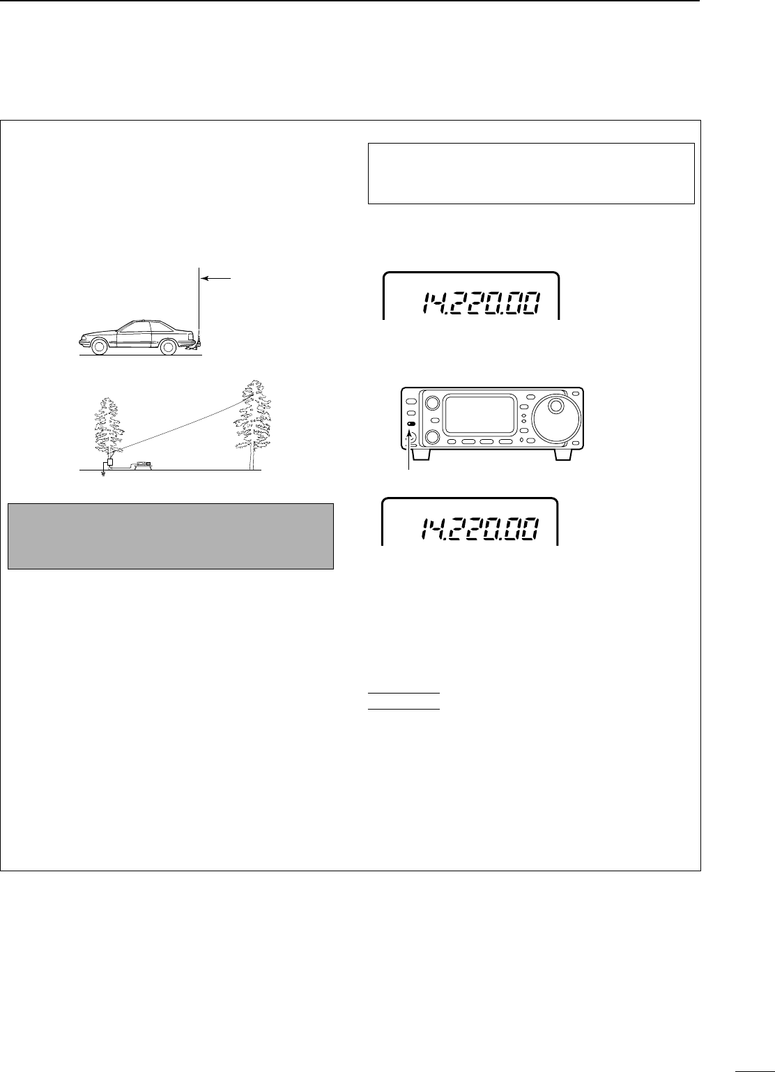
28
4
RECEIVE AND TRANSMIT
The AH-4 matches the IC-706MKIIG to a long wire
antenna more than 7 m/23 ft long (3.5 MHz and
above).
•See p. 14 for connection.
•See the AH-4 instruction manual for AH-4 installation and
antenna connection details.
NNEEVVEERRoperate the AH-4 without an antenna wire.
The tuner and transceiver will be damaged.
NNEEVVEERRoperate the AH-4 when it is ungrounded.
Transmitting before tuning may damage the trans-
ceiver. Note that the AH-4 cannot tune when using a
1⁄2λ long wire or multiple of the operating frequency.
NNoottee::The AH-4 can be used for HF bands and the 50
MHz band only.
AAHH--44 ooppeerraattiioonn
➀Set the desired frequency in an HF band.
•The AH-4 will not operate on frequencies outside of ham
bands.
➁Push and hold [TUNER] for 2 sec.
•The [TUNER] light flashes and “CW” appears while tun-
ing.
➂The [TUNER] light lights constantly when tuning is
complete.
•When the connected wire cannot be tuned, the
[TUNER] light goes out, the AH-4 is bypassed and the
antenna wire is connected to the antenna connector on
the transceiver directly.
➃To bypass the AH-4 manually, push [TUNER].
•PPTTTT ttuunnee ffuunnccttiioonn
The AH-4 is always tuned when the PTT is pushed
after the frequency is changed (more than 1%). This
function removes the “push and hold [TUNER]”
operation and activates first transmission on the new
frequency. This function is turned ON in initial set
mode, item 13 (p. 54).
DOOppttiioonnaall AAHH--44
AAUUTTOOMMAATTIICCAANNTTEENNNNAATTUUNNEERR
ooppeerraattiioonn
AH-4 setting example:
For mobile operation
For outdoor operation
Long wire
Optional AH-2b
antenna element
RWWAARRNNIINNGG:: HHIIGGHH VVOOLLTTAAGGEE!!
NNEEVVEERRtouch the antenna element while tuning
or transmitting.
Tuning is required for each frequency. BBee ssuurreeto
re-tune the antenna before transmitting when you
change the frequency—even slightly.
USB
CW
Push [TUNER] for 2 sec.
CONVENIENT
IC-706MKIIG.qxd 02.3.27 13:53 Page 28
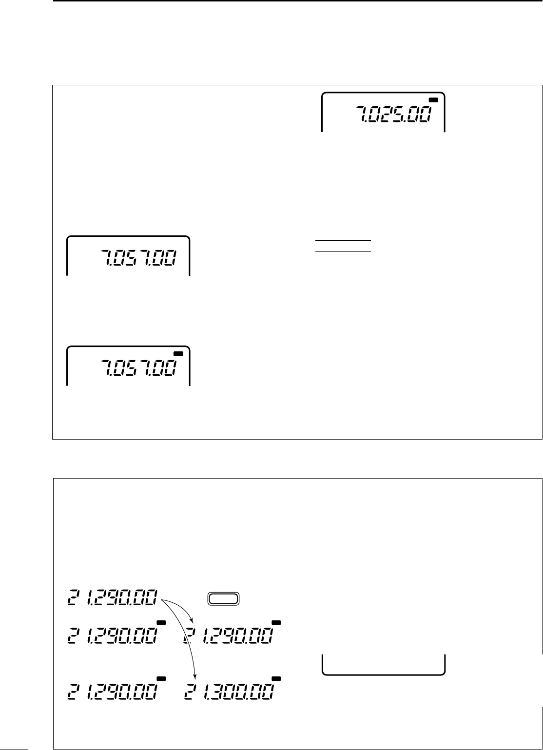
29
4RECEIVE AND TRANSMIT
Split frequency operation allows you to transmit and
receive on two different frequencies. Split frequency
operation uses 2 frequencies, one in VFO A and the
other in VFO B.
Following is an example of setting 7.057 MHz, CW
mode in VFO A (for receive) and 7.025 MHz, CW
mode in VFO B (for transmit).
➀Select VFO A and set the frequency to 7.057
MHz/CW.
•[(F-2)A/B] is available when M1 appears.
•[(F-3)V/M] is available when M2 appears.
➁Push or push and hold [(F-1)SPL] in the M1 dis-
play.
➥Push [SPL]: activates split only.
➥Push and hold [SPL]: activates the quick split
below.
➂To change the receive frequency, rotate the main
dial; to change the transmit frequency, rotate the
main dial while pushing [(F-3)XFC].
•The transmit frequency can be monitored while pushing
[(F-3)XFC].
•Split operation is now set for receive on 7.057 MHz/CW
and transmit on 7.025 MHz/CW.
To exchange the transmit and receive frequencies,
push [(F-2)A/B] in M1.
CONVENIENT
The G3 display conveniently shows the transmit fre-
quency during split frequency operation and [(F-3)Ñ]
allows you to change the transmit frequency.
•SSpplliitt lloocckk ffuunnccttiioonn
The split lock function is convenient for changing
only the transmit frequency. Otherwise, accidentally
releasing the [(F-3)XFC] switch while rotating the
main dial changes the receive frequency. The split
lock’s effectiveness can be selected in initial set
mode (item 12) for both receive and transmit fre-
quencies; or only the receive frequency. (p. 52)
DQQuuiicckk sspplliitt ffuunnccttiioonn
In M1, when you push [(F-1)SPL] for 2 sec., split fre-
quency operation is turned ON and VFO B is auto-
matically changed according to the plus/minus pre-
programmed shift frequency set in initial set mode (or
equalized when 0 kHz is programmed as the split shift
frequency). This shortens the time needed to start
split frequency operation—great for DX’ing.
The quick split function is ON by default. If desired, it
can be turned OFF in initial set mode (p. 51). In this
case, pushing [(F-1)SPL] for 2 sec. has the same
effect as pushing [(F-1)SPL] momentarily as in normal
split operation.
PPRROOGGRRAAMMMMIINNGG SSPPLLIITT SSHHIIFFTT FFRREEQQUUEENNCCYY
➀Push [POWER] to turn power OFF.
➁While pushing [LOCK], push [POWER] to turn
power ON and enter initial set mode.
➂Select “SPL OFFSET” using [MENU], [M-CH] or
the [Y]/[Z] keys, then rotate the main dial to select
the desired split offset.
•The split offset can be selected from –4000 kHz to
+4000 kHz.
NNoottee::This setting is not valid for FM operation. This
is because FM operation uses the duplex setting for
repeater operation (next page).
VFO A
CW
SPL
VFO A
CW
SPL
VFO B
CW
VFO A
VFO A
SPL
SPL SPL
SPL
VFO A
VFO B
VFO B
No shift frequency is programmed.
+10 kHz is programmed as a shift
frequency.
Push for 2 sec.
SPL
F-1
16 SPL OFFSET
■SSpplliitt ffrreeqquueennccyy ooppeerraattiioonn
IC-706MKIIG.qxd 02.3.27 13:53 Page 29
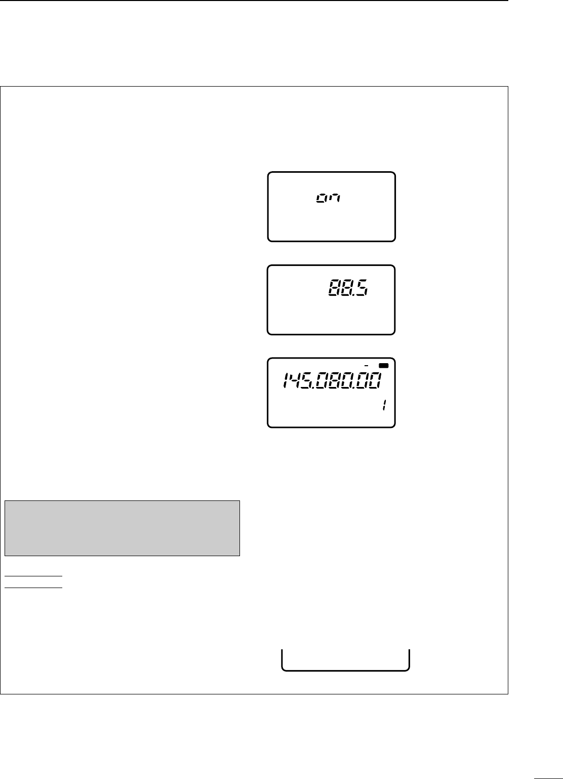
30
4
RECEIVE AND TRANSMIT
DRReeppeeaatteerr ooppeerraattiioonn
A repeater amplifies received signals and retransmits
them at a different frequency. When using a repeater,
the transmit frequency is shifted from the receive fre-
quency by an offset frequency. A repeater can be
accessed using split frequency operation with the
shift frequency set to the repeater’s offset frequency.
qSet the offset frequency and turn ON the quick
split function in initial set mode in advance (p. 52).
•If the quick split function is turned OFF, both transmit
and receive must be set separately.
wPush [MODE] one or more times to select FM
mode, then set the receive frequency.
e
Select a suitable tone frequency in quick set mode.
➥Push [DISPLAY] for 2 sec., then push [MENU]
one or more times to select “Q6 RPTR TONE.”
•If FM mode has not been selected, this item does not
appear.
➥Rotate the main dial to set a subaudible tone fre-
quency.
➥Push [DISPLAY] to exit quick set mode.
rPush [(F-1)SPL] for 2 sec. (in the M1 display) to
activate the split frequency function (duplex func-
tion) with the pre-selected offset.
•When a subaudible tone frequency is selected in e,
“FM-T” is selected simultaneously.
tPush and hold [PTT] to transmit; release [PTT] to
receive.
•Push and hold [(F-3)TON] in the M4 display while push-
ing [PTT] to send the 1750 Hz tone burst. (p. 32)
yTo check the repeater input frequency (direct sig-
nal from the other station), push and hold
[(F-3)XFC] in the M1 display.
uTo return to simplex operation, push [(F-1)SPL].
Each memory channel can store a tone frequency
and an offset frequency, as well as the operating fre-
quency. Store repeater information into memory
channels for quick and easy access to repeaters.
PPRROOGGRRAAMMMMIINNGG DDUUPPLLEEXX SSHHIIFFTT FFRREEQQUUEENNCCYY
➀Push [POWER] to turn power OFF.
➁While pushing [LOCK], push [POWER] to turn
power ON and enter initial set mode.
➂Select “DUP 144M” using [MENU] or the
[UP]/[DN] keys, then rotate the main dial to select
the desired duplex offset.
•The duplex offset can be selected from –4000 kHz to
+4000 kHz.
CONVENIENT
NNOOTTEE::The split function may not be turned off
when you change the operating band, push
[(F-1)SPL] again to turn off the split function after
you finish the repeater operation.
12 QUICK SPLIT
Turn the quick split
function ON.
(Initial set mode default
is ON.)
Q6 RPTR TONE
Set the tone frequency
(quick set mode).
See p. 49 for setting de-
tails and available fre-
quencies.
FM T
SPL
CH
VFO A
S1 5379204060dB
FM T
M4 VOX DUP TON
PO510
17 DUP 144M
IC-706MKIIG.qxd 02.3.27 13:53 Page 30
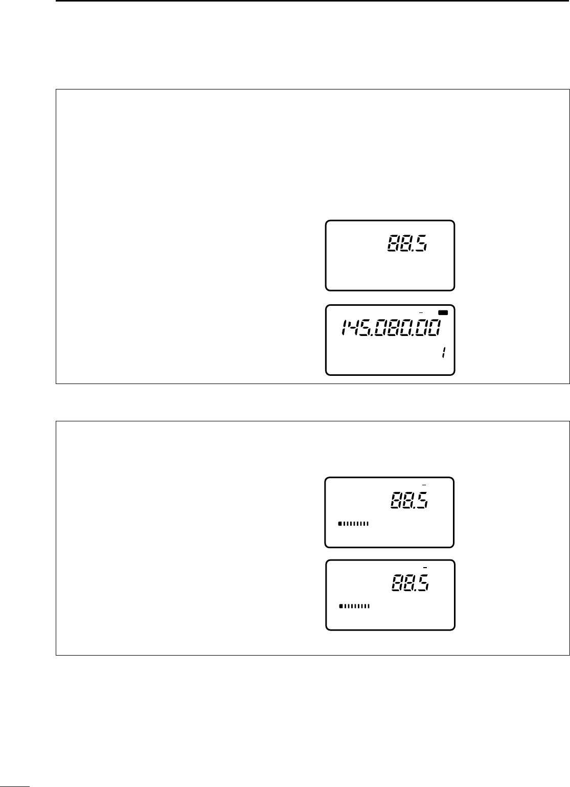
31
4RECEIVE AND TRANSMIT
Tone squelch operation is a method of communica-
tions using selective calling. Only received signals
having a matching tone will open the squelch. Before
communicating using tone squelch, all members of
your party must agree on the tone squelch frequency
to use.
➀Push [MODE] one or more times to select FM
mode.
➁
Push and hold [DISPLAY] to enter Quick Set mode.
➂Push [MENU] one or more times to select item Q7
TONE SQL.
•[Y]/[Z] or [M-CH] can also be used.
➃Rotate the main dial to select the desired subaudi-
ble tone frequency.
•Available tone frequencies are the same as for repeater
tone operation (see previous page).
➄Select M4 and turn the tone squelch function ON.
➥Push [(F-3)TON] to toggle tone squelch opera-
tion ON and OFF.
•When tone squelch is turned ON, “TSQL” appears in
the display.
➅Communicate in the usual manner.
•Push [PTT] to transmit; release to receive.
By monitoring a signal that is being transmitted on a
repeater input frequency, you can determine the
tone frequency necessary to open a repeater.
➀During tone squelch or repeater operation, push
and hold [DISPLAY] to enter Quick Set mode.
➁Push [MENU] one or more times to select item Q8
T-SQL SCN during tone squelch operation, or
Q8 RPTR-T SCN during repeater operation.
•[Y]/[Z] or [M-CH] can also be used.
➂Push [(F-3)SCN] to toggle tone scan operation ON
and OFF.
•While scanning tone frequencies are displayed instead
of the operating frequency.
•When a matched tone is detected, tone scan automati-
cally stops, the matched tone is displayed and the
repeater tone (or tone squelch tone) setting is automat-
ically adjusted accordingly.
➃Push [DISPLAY] to return to the main menu.
■TToonnee ssqquueellcchh ooppeerraattiioonn
■TToonnee ssccaann ooppeerraattiioonn
Q7 TONE SQL
Set the tone frequency
(quick set mode).
See p. 49 for setting de-
tails and available fre-
quencies.
During tone squelch op-
eration.
PO
S1
5
53792040
10
60dB
FM TSQL
Q8 T-SQL SCN
During repeater operation.
PO
S1
5
53792040
10
60dB
FM T
Q8 RPTR-T SCN
FM TSQL
SPL
CH
VFO A
S1 5379204060dB
M4 VOX DUP TON
PO510
IC-706MKIIG.qxd 02.3.27 13:53 Page 31
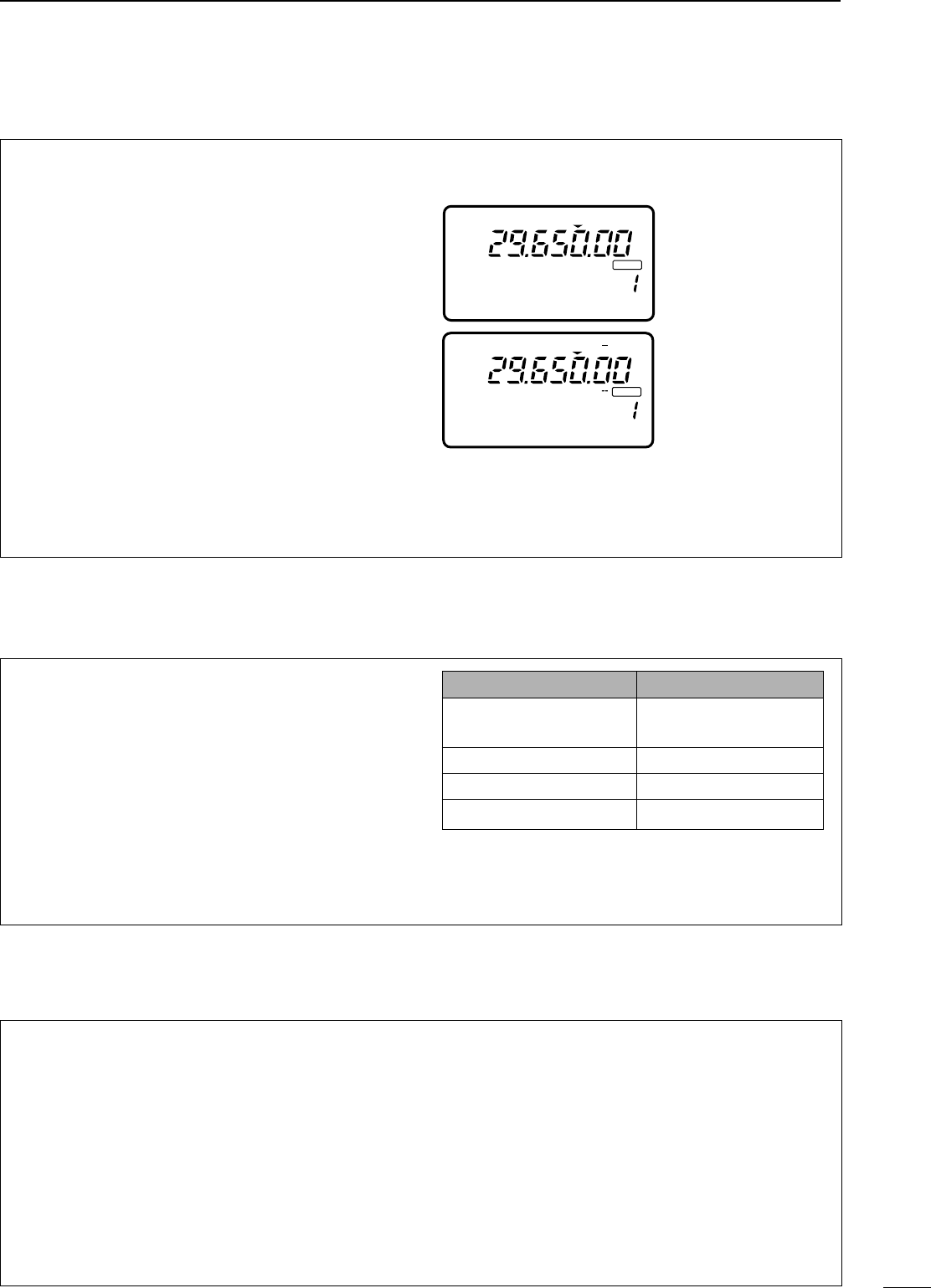
32
4
RECEIVE AND TRANSMIT
This function allows you to set repeater operation
with the push of one switch.
➀Push [(Y)BAND]/[(Z)BAND] to select the 28 MHz
band.
➁Rotate [DIAL] to select the operating frequency.
➂Push [MODE] one or more times to select FM.
➃Select M4 and turn the one-touch repeater func-
tion ON.
➥Push and hold [(F-2)DUP] to toggle the one-
touch repeater function ON and OFF.
•When the one-touch repeater function is turned ON,
“DUP” (duplex indicator) and “T” (tone frequency
indicator) appear in the display.
•Be sure to set the duplex direction and offset in ini-
tial set mode in advance (p. 52).
•Push [(F-2)DUP] to toggle the duplex direction.
☞NNOOTTEE::When you want to transmit a 1750 Hz tone,
while pushing [PTT], push [(F-3)TON] in the M4
display during repeater operation.
■OOnnee--ttoouucchh rreeppeeaatteerr ffuunnccttiioonn
This function automatically activates the repeater set-
tings (DUP+ or DUP– and tone encoder ON/OFF)
when the operating frequency falls within the gener-
al output frequency range and deactivates them
when outside of the range.
Set the auto repeater function ON or OFF in initial set
mode in advance (p. 53). When set ON, repeater set-
tings are automatically activated according to the
table at right.
☞NNOOTTEE::This function is available for the USA ver-
sion only.
■AAuuttoo rreeppeeaatteerr ffuunnccttiioonn
FFRREEQQUUEENNCCYY
DDUUPPLLEEXX DDIIRREECCTTIIOONN
145.200–145.495 MHz “DUP–” appears
146.610–146.995 MHz
147.000–147.395 MHz “DUP+” appears
442.000–444.995 MHz “DUP+” appears
447.000–449.995 MHz “DUP–” appears
CH
VFO A
P
O
S1
5
53792040
10
60dB
FM
BLANK
M1 SPL A/B A=B
CH
VFO A
DUP
P
O
S1
5
53792040
10
60dB
FM T
BLANK
M4 VOX DUP TON
A 1750 Hz tone is required to access most European
repeaters. When you want to transmit a 1750 Hz
tone, there are two methods described as follows;
➥While pushing [PTT], push [(F-3)TON] in the M4
display during repeater operation. (pgs. 30, 32)
➥While pushing [PTT], push [F-2] in the G4 mem-
ory name display.
☞NNOOTTEE::Program the memory names and the
appropriate repeaters information before using
this function. (p, 41)
■11775500HHzz ttoonnee bbuurrsstt ((FFMM mmooddee oonnllyy))
IC-706MKIIG.qxd 02.3.27 13:53 Page 32
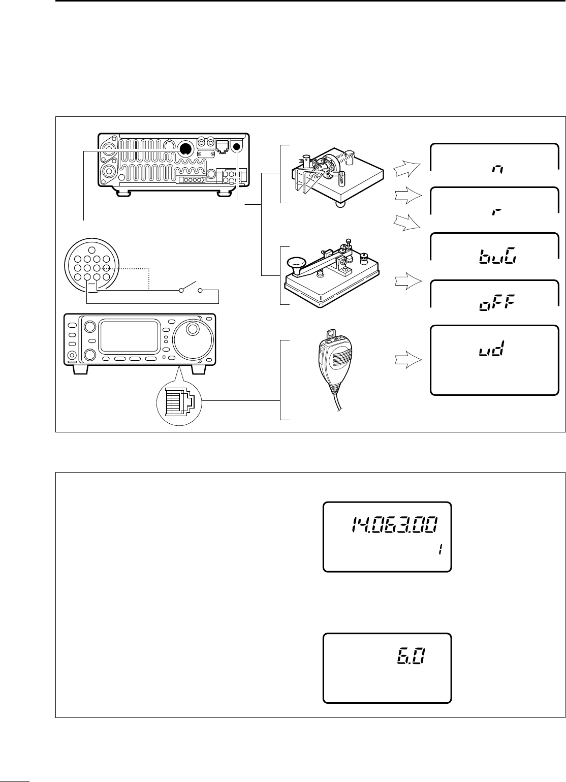
33
4RECEIVE AND TRANSMIT
DCCoonnnneeccttiioonnss ffoorr CCWW
DCCWW ooppeerraattiioonn
➀Connect a paddle or straight key as above.
➁Select CW (or CWå) mode with [MODE].
➂Set CW break-in operation as semi break-in, full
break-in or OFF.
•
Push [DISPLAY] one or two times to select M, if neces-
sary.
•Push [MENU] one or more times to select M4.
•Push [(F-2)BRK] one or more times to select the
desired condition:
➧“F-BK”: full break-in
➧“BK”: semi break-in
➧No indicator: no break-in (ACC socket connection is
necessary as above.)
➃Set the CW delay time when semi break-in opera-
tion is selected.
➥Push [DISPLAY] for 2 sec. to select quick set
mode; push [MENU] one or more times to select
Q3 BK-IN DELAY; then rotate the main dial
to set the desired delay time (see p. 48 for
details).
CW
Q4 CW PADDLE
CW
CW
CW
CW
Paddle
[ELEC KEY]
[MICROPHONE]
See p. 34 for
connection details:
Paddle operation from
front panel MIC connector
.
Straight key
Microphone
Quick set mode settingRear panel
4
8
12
144/430 MHz
HF/50 MHz
[ACC]
123
765
9
10 11
13
For no break-in operation:
Connect an external switch such
as a foot switch; or use the
RTTY SEND terminal for all
bands. (See p. 35.)
■FFuunnccttiioonnss ffoorr CCWW
BK VFO A
CW
CW
Q3 BK-IN DELAY
M4 BRK1/4 AGC
CW mode and semi
break-in operation is
selected.
Delay time of 6.0 dots is
selected in quick set
mode for semi break-in
operation.
CH
PO
S1
5
53792040
10
60dB
IC-706MKIIG.qxd 02.3.27 13:53 Page 33
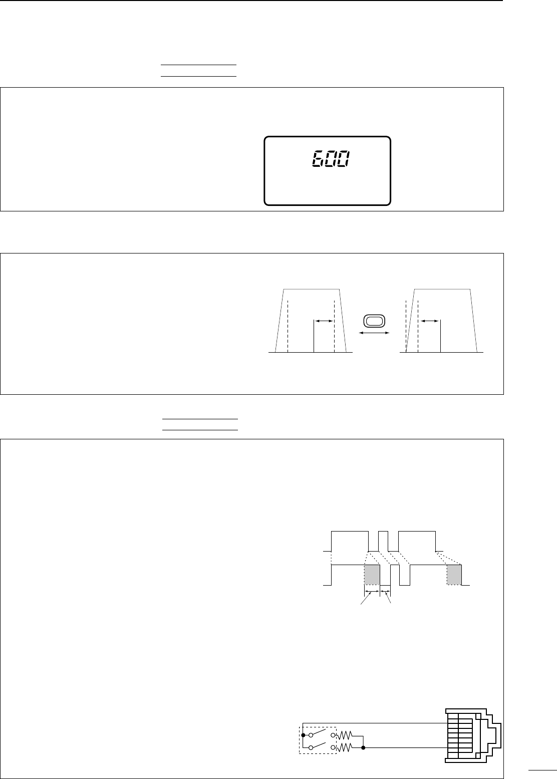
34
4
RECEIVE AND TRANSMIT
DCCWW ppiittcchh ccoonnttrrooll
The received CW audio pitch and monitored CW
audio pitch can be adjusted to suit your preferences
(300 to 900 Hz) without changing the operating fre-
quency.
➀Push [MODE] one or more times to select CW
mode.
➁Select CW PITCH in quick set mode.
•Push [DISP] for 2 sec. then push [MENU] one or more
times.
➂Rotate the main dial to set the desired pitch.
➃Push [DISPLAY] to exit quick set mode.
Q2 CW PITCH
This shows the default
setting for the CW pitch
control (600 Hz).
CW
QUICK SET MODE
DCCWW rreevveerrssee mmooddee
The CWå(CW Reverse) mode receives CW signals
with a reverse side CW carrier point like that of LSB
and USB modes. Use this mode when interference
signals are near the desired signal and you want to
change the interference tone.
➀Push [MODE] one or more times to select CW
mode.
➁Push and hold to toggle between CW and CWå
modes.
•Check the interference tone.
• Receive audio tone response
(Reverse) CWå
MODE
(Normal) CW
BFO
600 Hz
signal
inteference signal
600 Hz
BFO
inteference
DEElleeccttrroonniicc CCWW kkeeyyeerr
The IC-706MKIIG has an electronic keyer. Both key-
ing speed and weight (the ratio of dot : space : dash)
can be set in quick set mode.
•SSeettttiinngg tthhee eelleeccttrroonniicc kkeeyyeerr
➀Select CW mode with [MODE].
➁
Push [DISPLAY] for 2 sec. to enter quick set mode.
➂Push [MENU] one or more times to select item Q4
CW PADDLE, then rotate the main dial to select
the paddle type.
•When “ud” is selected, the up/down switches on the
microphone can be used as a paddle.
➃Push [MENU] two more times to select item Q6
RATIO, then rotate the main dial to select the
desired weight.
•Key weight can be selected from 2.8 to 4.5.
•Check the selected ratio with the side tone function in
CW mode.
➄
Push [DISPLAY] momentarily to exit quick set mode.
PPaaddddllee ooppeerraattiioonn ffrroomm ffrroonntt ppaanneell MMIICCccoonnnneeccttoorr
Connect a CW paddle as at right to operate an elec-
tronic keyer from the front panel MIC connector.
•This function is available from the front panel mic
connector only.
•Be sure to select item “n,” “r,” “buG” or “oFF” in Q4
CW PADDLE in quick set mode. (p. 49)
•Connect straight key to “DOT” side.
KEYING WEIGHT EXAMPLE: morse code “K”
*SPACE and DOT length can be adjusted with “Q5 KEY
SPEED” only.
DASH
Weight setting:
1:1:3 (default)
Weight setting:
Adjusted
DASH
DOT
(Fixed*)
Adjustable range SPACE (Fixed*)
QUICK SET MODE
front panel
MIC connector
MIC U/D
CW
paddle
DOT
E
DASH
➁
➆
3.9 kΩ ±5%
2.2 kΩ ±5%
IC-706MKIIG.qxd 02.3.27 13:53 Page 34
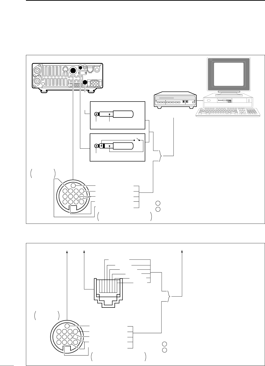
35
4RECEIVE AND TRANSMIT
DCCoonnnneeccttiioonnss ffoorr RRTTTTYY ((FFSSKK))
DCCoonnnneeccttiioonnss ffoorr AAFFSSKK
Rear panel
TU or TNC
Personal computer
Rear panel
view
Colors refer to connection
to the supplied ACC cable.
Use either the ACC or one of the two 1/8˝ plugs
*1Connect SQL line when required.
SQL*1 (light green)
AF out (light blue)
MSEND*2
GND (red)
FSKK (black)
GND
GND
AF
3-conductor 1/8˝ plug (supplied)
2-conductor 1/8˝ plug
FSKK
SEND
[RTTY]
[ACC]
[EXT SP]
123 3
4
567
7
8
9101112
13
HF/50 MHz: orange
144 MHz: purple
*2
■FFuunnccttiioonnss ffoorr RRTTTTYY
To a TU or TNC
and personal computer
Use either the ACC or microphone connector
SQL*1 (light green)
AF out (light blue)
AF in (pink)
HSEND*2
GND (red)
➇ SQL
To [MIC]
To [ACC]
1234
567
7
8
9101112
13
➂ AF out
➃ PTT
➄ GND
➅ MIC
➆ GND
Rear panel
view
Colors refer to connection
to the supplied ACC cable.
*1Connect SQL line when required.
3HF/50 MHz: orange
144 MHz: purple
*2
IC-706MKIIG.qxd 02.3.27 13:53 Page 35
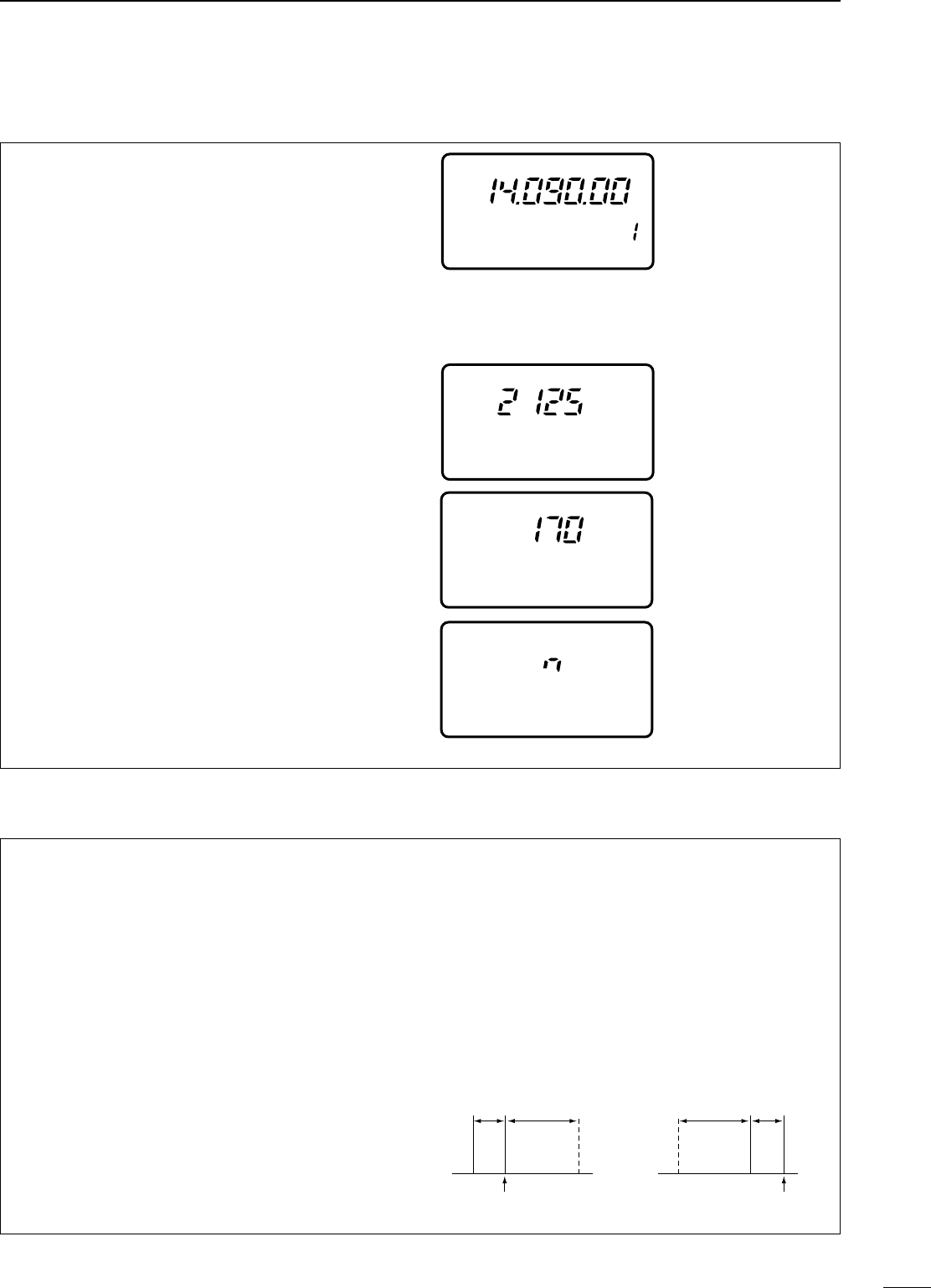
36
4
RECEIVE AND TRANSMIT
DRRTTTTYY ((FFSSKK)) ooppeerraattiioonn
➀Connect a terminal unit as at left.
➁Select RTTY (or åRTTY—see bottom of page)
mode with [MODE].
➂Select the desired FSK tone/shift frequencies and
keying polarity as below.
➃Set the desired frequency with the main dial.
•Use [(F-1)1/4] in the M4 display when critical setting is
required.
➄Operate the connected PC or TNC (TU).
PPRREESSEETTTTIINNGG FFOORR RRTTTTYY
TToonnee ffrreeqquueennccyy
➀
Push [DISPLAY] for 2 sec. to select quick set mode.
➁Push [MENU] one or more times to select Q2
RTTY TONE; then rotate the main dial to select
the desired tone frequency (p. 48).
SShhiifftt ffrreeqquueennccyy
➀
Push [DISPLAY] for 2 sec. to select quick set mode.
➁Push [MENU] one or more times to select Q3
RTTY SHIFT; then rotate the main dial to select
the desired shift frequency (p. 48).
RRTTTTYY kkeeyyiinngg
➀
Push [DISPLAY] for 2 sec. to select quick set
mode.
➁Push [MENU] one or more times to select Q4
RTTY KEYING; then rotate the main dial to
select the desired keying polarity (p. 48).
➀Connect a terminal unit as at left.
➁Select SSB (LSB) mode with [MODE].
•Generally, LSB is used on the HF bands and FM is used
for the VHF band.
➂Select the desired FSK tone/shift frequencies and
keying polarity as below.
➃Set the desired frequency with the main dial.
•Use [(F-1)1/4] in the M4 display when critical setting is
required.
➄Operate the connected PC or TNC (TU).
PPRREESSEETTTTIINNGG FFOORR RRTTTTYY
TToonnee ffrreeqquueennccyy
Same as above.
SShhiifftt ffrreeqquueennccyy
Same as above.
RRTTTTYY kkeeyyiinngg
Same as above.
RRTTTTYY rreevveerrssee mmooddee
Received characters are occasionally garbled when
the receive signal is reversed between MARK and
SPACE. This reversal can be caused by incorrect
TNC connections, settings, commands, etc.
To receive a reversed RTTY signal correctly, select
åRTTY (RTTY reverse) mode.
➥Push [MODE] for 1 sec. (while RTTY is selected) to
select åRTTY mode.
•Check the receive signal.
CH
VFO A
R
TT
Y
M1 SPL A/B A=B
RTTY mode is selected.
PO
S1
5
53792040
10
60dB
R
TT
Y
Q2 RTTY TONE
RTTY mark frequency
is set to 2125 Hz.
2125 and 1615 Hz are
available.
R
TT
Y
Q3 RTTY SHIFT
RTTY shift frequency is
set to 170 Hz.
170/200/425 Hz are
available.
R
TT
Y
Q4 RTTY KEYING
RTTY keying is set to
‘normal’.
normal: key open=mark
key close=space
reverse: key open=space
key close=mark
DRRTTTTYY ((AAFFSSKK)) ooppeerraattiioonn
ReverseNormal
BFO
170
Hz
2125
Hz 170
Hz
2125
Hz
BFO
mark
space
displayed freq.displayed freq.
mark
space
IC-706MKIIG.qxd 02.3.27 13:53 Page 36
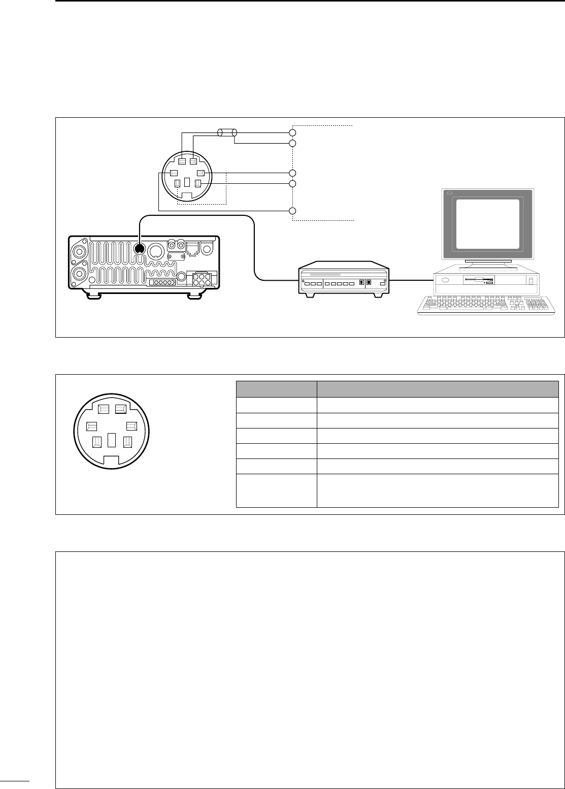
37
4RECEIVE AND TRANSMIT
■PPaacckkeett ooppeerraattiioonn
DCCoonnnneeccttiioonnss ffoorr ppaacckkeett
Rear panel
DATA
PTT
PTTP
DATA IN
SQL
RX AUDIO
GND
TX AUDIO
TNC SIDE
TU or TNC
RS-232C
Personal computer
qw
e
y
t
r
AF OUT
DATA OUT
GND
SQ
qw
e
y
t
r
PPIINN ##//NNAAMMEEDDEESSCCRRIIPPTTIIOONN
q DDAATTAA IINNCommunication data input.
w GGNNDDGround for DATA IN, DATA OUT and AF OUT.
e PPTTTTPPTransmits when grounded.
r DDAATTAA OOUUTTOutputs 9600 bps receive data.
t AAFF OOUUTTOutputs 1200 bps receive data.
y SSQQSquelch output.
Goes to ground when squelch opens.
Rear panel view
DAAddjjuussttiinngg tthhee ttrraannssmmiitt ssiiggnnaall oouuttppuutt ffrroomm tthhee TTNNCC
☞NNOOTTEE:: For packet operation the transceiver can
be set to one of two data speeds: 1200 bps or
9600 bps. Data speed is set in initial set mode (see
p. 54 item 29 9600 MODE).
Data speed is set in initial set mode (see p. 53 item 29
9600 MODE).When setting data transmission
speed to 9600 bps, the
DATA
signal coming from the
TNC is applied exclusively to the internal limiter cir-
cuitry to automatically maintain bandwidth.
NEVER apply data levels from the TNC of over 0.6
Vp-p, otherwise the transceiver will not be able to
maintain the band width and may possibly interfere
with other stations.
☞NNOOTTEE:: Read the instructions supplied with your
TNC carefully before attempting packet operation
with the IC-706MKIIG.
1. When using a level meter or synchroscope, adjust
the TX audio level (
DATA IN
level) from the TNC as
follows.
0.4 Vp-p (0.2 Vrms): recommended level
0.2 Vp-p–0.5 Vp-p (0.1 Vrms–0.25 Vrms):
acceptable level
2. When not using a measuring device.
➀Connect the IC-706MKIIG to a TNC.
➁Enter a test mode (“CAL”, etc.) on the TNC, then
transmit some test data.
➂When the transceiver fails to transmit test data or
transmits sporadically (TX indicator doesn’t appear
or flashes):
Decrease the TNC output level until the transmit
indicator lights continuously.
When transmission is not successful even though
the TX indicator lights continuously:
Increase the TNC output level.
DDDaattaa ssoocckkeett
IC-706MKIIG.qxd 02.3.27 13:53 Page 37
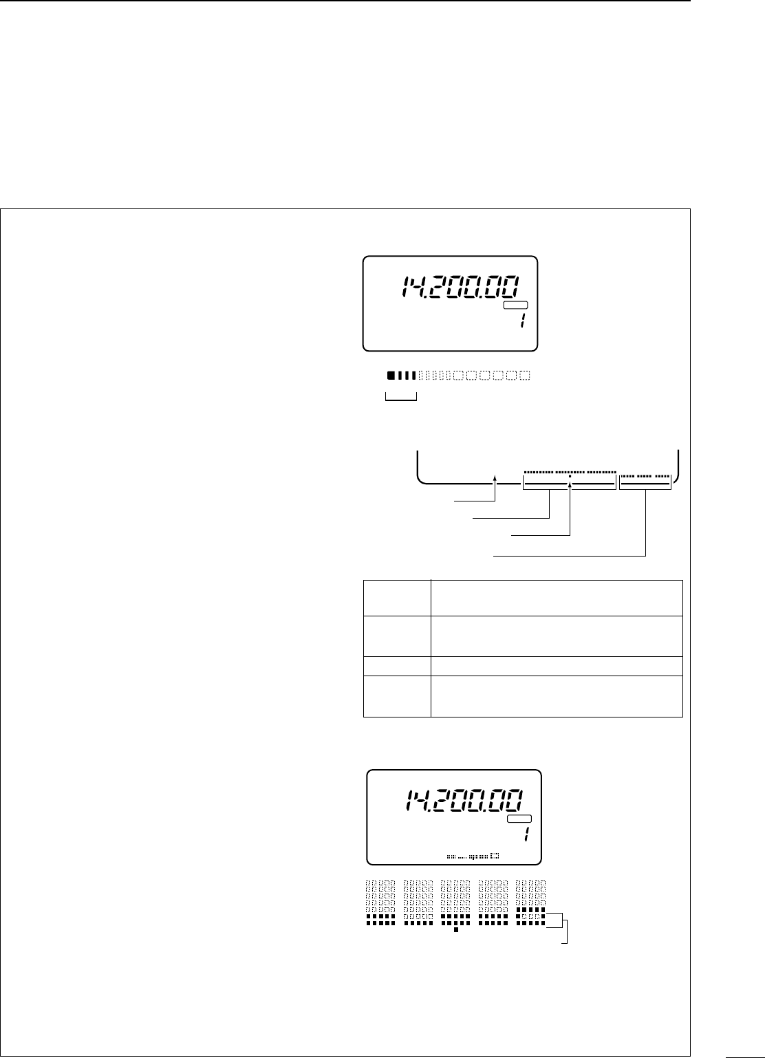
38
4
RECEIVE AND TRANSMIT
The IC-706MKIIG can measure SWR in 2 ways:
(A) Spot measurement; or (B) Plot measurement.
((AA)) SSppoott mmeeaassuurreemmeenntt
➀Confirm that the output power is over 30 W.
➁Push [MENU] one or more times to select M3.
➂Push [(F3)MET] to select the SWR meter.
➃Push [MODE] one or more times to select CW or
RTTY operation.
•Key down or push [PTT] to transmit; then read the actu-
al SWR from the meter:
➠≤1.5 well matched antenna
➠>1.5 check antenna or cable connection, etc.
((BB)) PPlloott mmeeaassuurreemmeenntt
Plot measurement allows you to measure the SWR
over an entire band.
qConfirm that the output power is over 30 W.
wPush [DISPLAY] twice to select G1 menu.
ePush [MENU] to select G2.
rSet the center frequency for the SWR to be mea-
sured.
tPush and hold [(F1)10k] one or more times to
select the desired frequency pitch.
yPush and hold [(F2)] one or more times to select
the desired step.
uAfter selecting the desired pitch and step, push
[(F3)STR] to measure the SWR.
•RTTY mode is selected automatically.
iPush and hold [PTT] to display the SWR in a bar
graph readout.
oWhen [PTT] is released, the frequency marker and
frequency indication move to the next frequency
to be measured.
!0Repeat steps iand oto measure SWR over the
entire frequency range.
!1When the measured SWR is less than 1.5, the
antenna is well matched.
■SSWWRR
The IC-706MKIIG has a built-in circuit for measuring
antenna SWR—no external equipment or special
adjustments are necessary.
☞NNOOTTEE:: TThhee SSWWRR ccaann oonnllyy bbee mmeeaassuurreedd oonn
AANNTT11,, HHFF//5500MMHHzz bbaannddss..
DMMeeaassuurriinngg SSWWRR
CH
VFO A
SWR
S1
1 1.5 2 3
5379
20 40 60dB
CW
BLANK
SWR 1 1.5 2 3 5 10
The best match is in this range.
∞
∞
M3 FIL NB MET
G2 10k STR
Frequency span
Step bar indication
Frequency indication mark
Measure start indicator
SSppaannPush [F-1] for 1 sec. to change the
selected span.
SStteepp bbaarr
Push [F-2] for 1 sec. to change the
step bar (3, 5, 7 or 9 steps are available.
MMaarrkkeerrIndicates the currently active step bar.
SSttaarrttFlashes while the SWR is being mea-
sured.
Step o
The antenna is well matched in this range
CH
VFO A
P
O
S1
5
5379
20 40
10
60dB
BLANK
G2 50k STR
4
.
0
3
.
5
3
.
0
2
.
5
2
.
0
1
.
5
1
.
0
R
TT
Y
IC-706MKIIG.qxd 02.3.27 13:53 Page 38
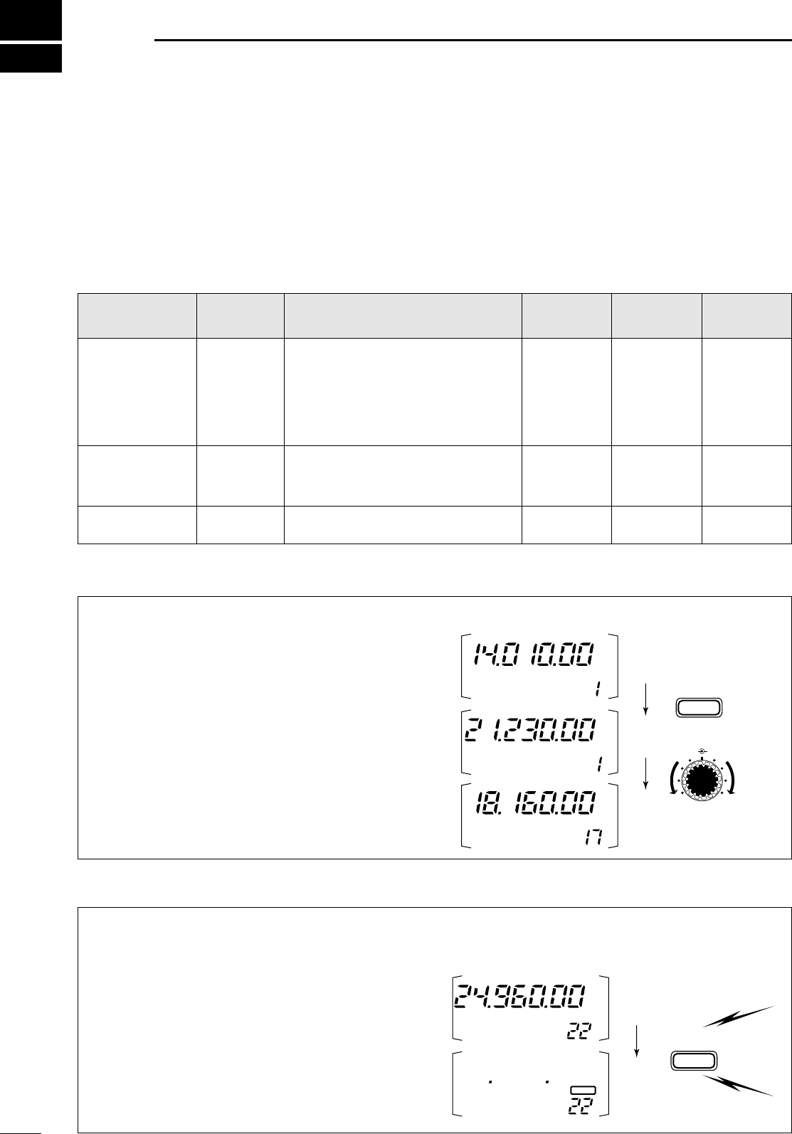
39
5MMEEMMOORRYY AANNDD SSCCAANN OOPPEERRAATTIIOONN
■MMeemmoorryy cchhaannnneellss
The transceiver has 105 memory channels (plus 2 call
channels). Memory mode is useful for quickly chang-
ing to often-used frequencies.
All 105 memory channels are tuneable which means
the programmed frequency can be tuned temporarily
with the main dial, etc., in memory mode.
➀Select M2 functions.
•Push [DISPLAY] 1 or 2 times to select M.
•Push [MENU] one or more times to select M2.
➁Push [(F-3)V/M] to select memory mode.
➂Rotate [M-CH] to select the desired memory chan-
nel.
•All memory channels including blank channels can be
selected.
•[UP]/[DN] on the microphone changes the frequency.
➃To return to VFO mode, push [(F-3)V/M] again.
Any unnecessary memory channels can be cleared.
The cleared memory channels become blank chan-
nels.
➀Push [(F-3)V/M] in the M2 display to select memo-
ry mode.
➁Rotate [M-CH] to select a memory channel to be
cleared.
➂Push [MCL(F-2)] for 2 sec. to clear the contents.
•The programmed frequency and operating mode disap-
pear and “}” appears.
➃To return to VFO mode, push [(F-3)V/M] again.
■MMeemmoorryy cchhaannnneell sseelleeccttiioonn
■MMeemmoorryy cclleeaarriinngg
NNoottee::During split frequency operation, programmed
memory contents can be called up to the SUB readout
(dot matrix portion of the display).
CW
CH
VFO A
[EXAMPLE]: Selecting memory channel 17.
V/M
F-3
USB
CH
MEMO
SPLIT
CH
MEMO
USB
M-CH SHIFT
MCL
F-2
SPLIT
Push for
2 sec.
CH
MEMO
USB
CH
MEMO
BLANK
MMEEMMOORRYY
CCHHAANNNNEELL
MMEEMMOORRYY
CCHHAANNNNEELL
NNUUMMBBEERR
CCAAPPAABBIILLIITTYYTTRRAANNSSFFEERR
TTOO VVFFOO
OOVVEERR--
WWRRIITTIINNGGCCLLEEAARR
RReegguullaarr
((sspplliitt mmeemmoorryy))1–99
Independent transmit and receive
frequencies and one mode in each
memory channel.
In addition, tone frequencies (or
1750 Hz tone burst) can also be
stored for repeater use.
Ye s Ye s Ye s
SSccaann eeddggeess1A–3B
(3 pair)
One frequency and one mode in
each memory channel as scan
edges for programmed scan.
Ye s Ye s No
CCaallll cchhaannnneell
((sspplliitt mmeemmoorryy))
C1 (144 MHz)
C2 (430 MHz)
Same as regular, but only 144/430
MHz band can be programmed. Ye s Ye s No
IC-706MKIIG.qxd 02.3.27 13:53 Page 39
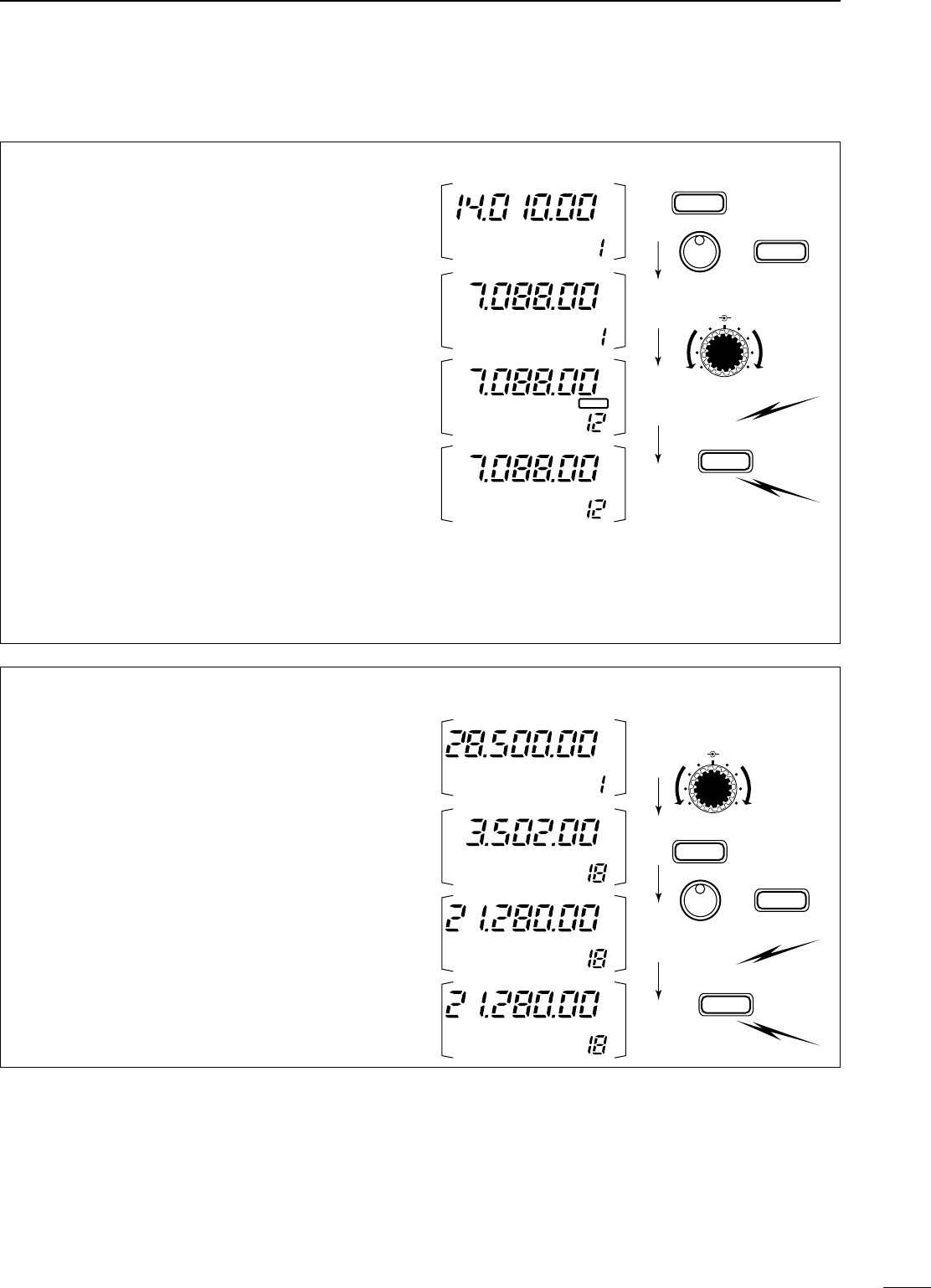
40
5
MEMORY AND SCAN OPERATION
•PPrrooggrraammmmiinngg iinn VVFFOO mmooddee
➀Select M2 functions.
•Push [DISPLAY] 1 or 2 times to select M.
•Push [MENU] one or more times to select the M2 func-
tions.
➁Set the desired frequency and operating mode in
VFO mode.
•If you want to program the split frequency function, pro-
gram both receive and transmit frequencies into VFO A
and B, then turn ON the split function.
•If you want to program a repeater function, set a tone
frequency (p. 49) in addition to the receive/transmit fre-
quencies.
➂Rotate [M-CH] to select the desired memory chan-
nel, or the call channel (144/430 MHz bands only).
•
Select memory mode to confirm the contents, if desired.
•“}” appears if the selected memory channel is a
blank channel (and does not have contents).
➃Push [(F-1)MW] for 2 sec. to program the displayed
frequency and operating mode into the memory
channel.
To check the programmed contents, push [(F-3)V/M]
to select memory mode; or, push [CALL] to select
the call channel.
■MMeemmoorryy//ccaallll pprrooggrraammmmiinngg
CW
CH
VFO A
[EXAMPLE]:
Programming 7.088 MHz/LSB into ch 12.
TS
MODE
MW
F-1
LSB
BLANK
SPLIT
CH
VFO A
LSB
CH
VFO A
LSB
CH
VFO A
Push for
2 sec.
M-CH SHIFT
•PPrrooggrraammmmiinngg iinn mmeemmoorryy mmooddee
➀Set the desired frequency and operating mode.
➁Select memory mode, then select the desired
memory channel with [M-CH].
•Push [Y]/[Z] when you want to program blank chan-
nels.
➂Push [(F-1)MW] for 2 sec. to program the displayed
frequency and operating mode into the memory
channel.
CH
[EXAMPLE]:
Programming 21.280 MHz/USB into
ch 18.
TS
MODE
MW
F-1
SPLIT
Push for
2 sec.
CH
MEMO
USB
CH
MEMO
USB
CH
MEMO
CW
CH
MEMO
USB
M-CH SHIFT
IC-706MKIIG.qxd 02.3.27 13:53 Page 40
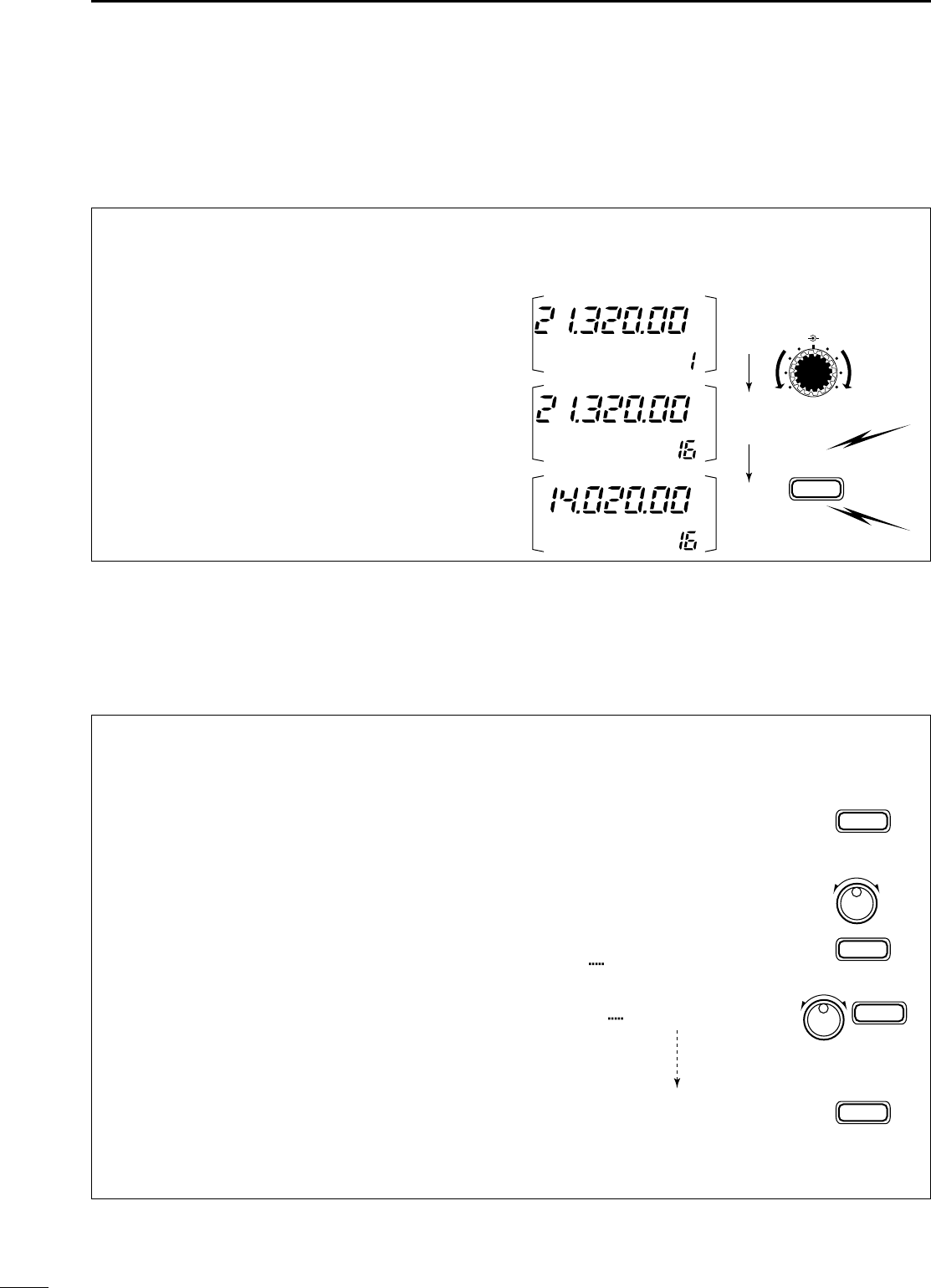
41
5MEMORY AND SCAN OPERATION
■FFrreeqquueennccyy ttrraannssffeerrrriinngg
The frequency and operating mode can be trans-
ferred from memory mode to VFO mode.
➀Select VFO mode with [(F-3)V/M] in the M2 dis-
play.
➁Select a memory channel with [M-CH].
•Select memory mode to confirm the memory channel’s
contents, if desired; then return to VFO mode.
•“}” appears if the selected memory channel is a
blank channel (and does not have contents). In this
case transferring is not possible.
➂Push [(F-2)MÜV] for 2 sec. to transfer the frequen-
cy and operating mode.
•Transferred frequency and operating mode appear in
the display.
•“MÜV” does not appear in memory mode. MÜV
F-2
SPLIT
Push for
2 sec.
[EXAMPLE]: Transferring contents of memory 16.
Operating frequency: 21.320 MHz/USB (VFO)
Contents of memory 16: 14.020 MHz/CW
CH
VFO A
USB
CH
VFO A
USB
CH
VFO A
CW
M-CH SHIFT
■MMeemmoorryy nnaammeess
All memory channels (including scan edges and the
call channel) can be tagged with alphanumeric names
of up to 9 characters each.
All common keyboard characters (ASCII characters 33
to 126) can be used, including numerals and punctua-
tion marks.
•CCaalllliinngg uupp mmeemmoorryy nnaammeess
➀Select the G4 display.
➥Push [DISPLAY] 1 or 2 times to select G.
➥Push [MENU] one or more times to select the
G4 display.
➁Select a memory channel with [M-CH].
•EEddiittiinngg ((pprrooggrraammmmiinngg)) mmeemmoorryy nnaammeess
➀Call up the desired memory (channel) name as
above.
➁Push [(F-3)É] to enter memory name edit mode.
•“name edit” appears briefly, then a flashing cursor
appears under the first character position.
➂Rotate the main dial to select the desired charac-
ter, then advance the cursor position.
•[(F-3)Ç] increments the cursor position; [(F-1)Å] decre-
ments the cursor position.
•[(F-2)] overwrites the character with a space.
➃Repeat this procedure until all desired characters
have been selected.
➄Push [(MENU)Ä] to exit memory name edit mode.
•The G4 display reappears and the programmed memo-
ry name is displayed.
G4 memory name
G4
G4 Repeater É
ÄÅÖ
name edit
É
F-3
Ç
F-3
Ç
F-3
Ä
MENU
ÄÅR
Ç
Ç
ÄÅRe Ç
ÄÅRepeaterÖÇ
É
IC-706MKIIG.qxd 02.3.27 13:53 Page 41
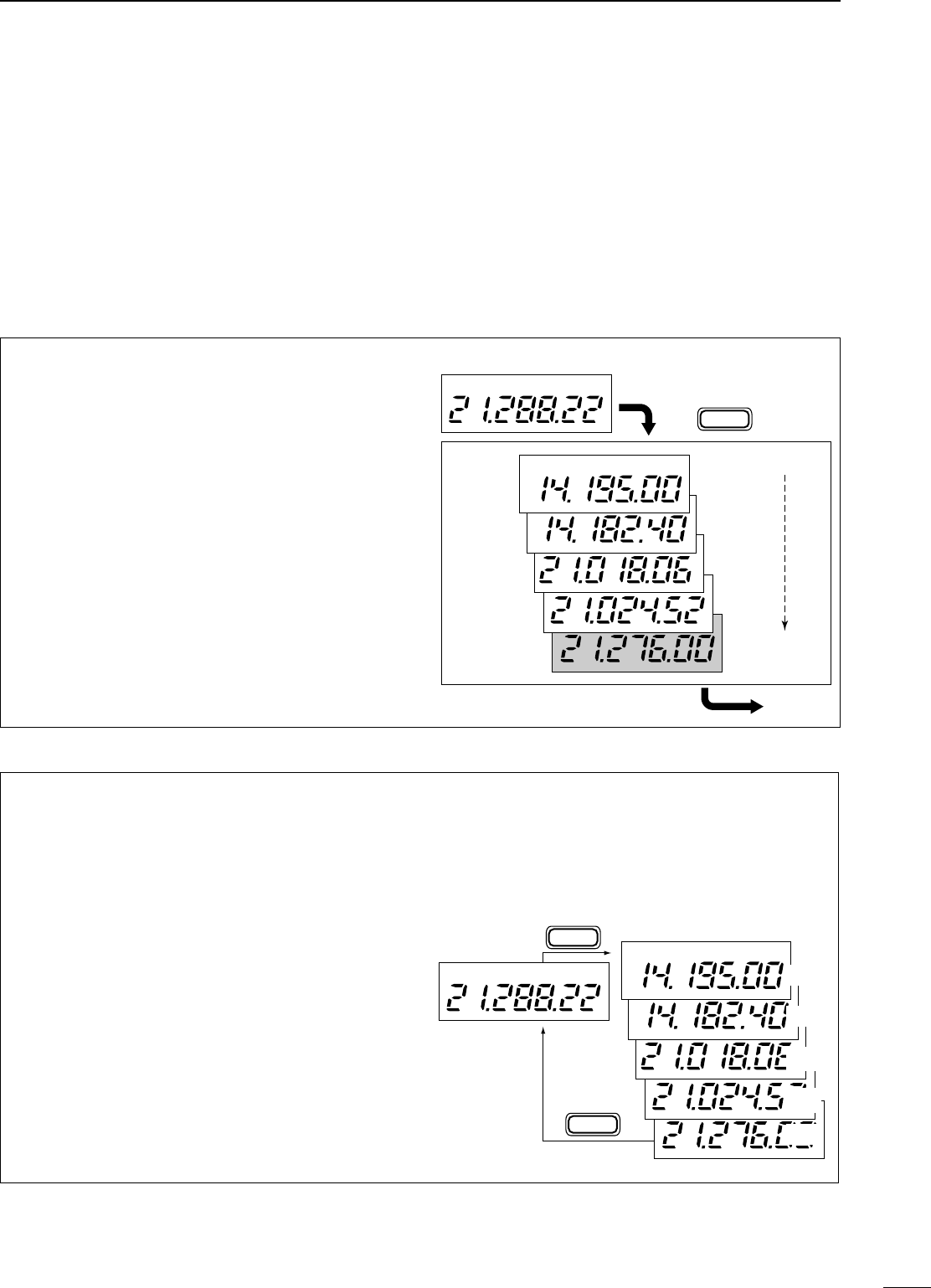
42
5
MEMORY AND SCAN OPERATION
•CCaalllliinngg uupp aa ffrreeqquueennccyy ffrroomm aa mmeemmoo ppaadd
You can simply call up the desired frequency and
operating mode of a memo pad by pushing
[(F-3)MPR] in the S1 display.
•Make sure S1 is selected in advance.
•Both VFO and memory modes can be use.
•The frequency and operating mode are called up, starting
from the most recently written.
When you call up a frequency and an operating
mode from memo pads with [(F-3)MPR], the previous-
ly displayed frequency and operating mode are auto-
matically stored in a temporary pad. The frequency
and operating mode in the temporary pad can be
recalled by pushing [(F-3)MPR] one or more times.
NNoottee::If you change the frequency or operating
mode called up from a memo pad, the frequency and
operating mode in the temporary pad are erased.
VFO or
MEMORY
mode
MEMO PADS
MPR
F-3
MPR
F-3
USB
USB
USB
USB
USB
USB
MP5
MP4
MP3
MP2
MP1
■MMeemmoo ppaaddss
The transceiver has a memo pad function to store fre-
quency and operating mode for easy write and recall.
The memo pads are separate from memory channels.
The default number of memo pads is 5, however, this
can be increased to 10 in initial set mode if desired
(p. 53).
Memo pads are convenient when you want to memo-
rize a frequency and operating mode temporarily,
such as when you find a DX station in a pile-up or when
a station is busy for a long time and you want to tem-
porarily search for other stations.
Use the transceiver’s memo pads instead of relying on
hastily scribbled notes that are easily misplaced.
•WWrriittiinngg ffrreeqquueenncciieess aanndd ooppeerraattiinngg mmooddeess
iinnttoo mmeemmoo ppaaddss
➀Select the S1 display.
•Push [DISPLAY] 1 or 2 times to select S.
•Push [MENU] one or more times to select S1.
➁Push [(F-2)MPW] to program the frequency into a
memo pad.
When you write a 6th frequency and operating
mode, the oldest written frequency and operating
mode are automatically erased to make room for the
new settings.
NNoottee::Each memo pad must have its own unique
combination of frequency and operating mode;
memo pads having identical settings cannot be writ-
ten.
Displayed frequency and mode
Push
Newest
MP5
MP4
MP3
MP2
MP1
The oldest written frequency
and mode are erased.
Oldest
MPW
F-2
USB
USB
USB
USB
USB
USB
IC-706MKIIG.qxd 02.3.27 13:53 Page 42
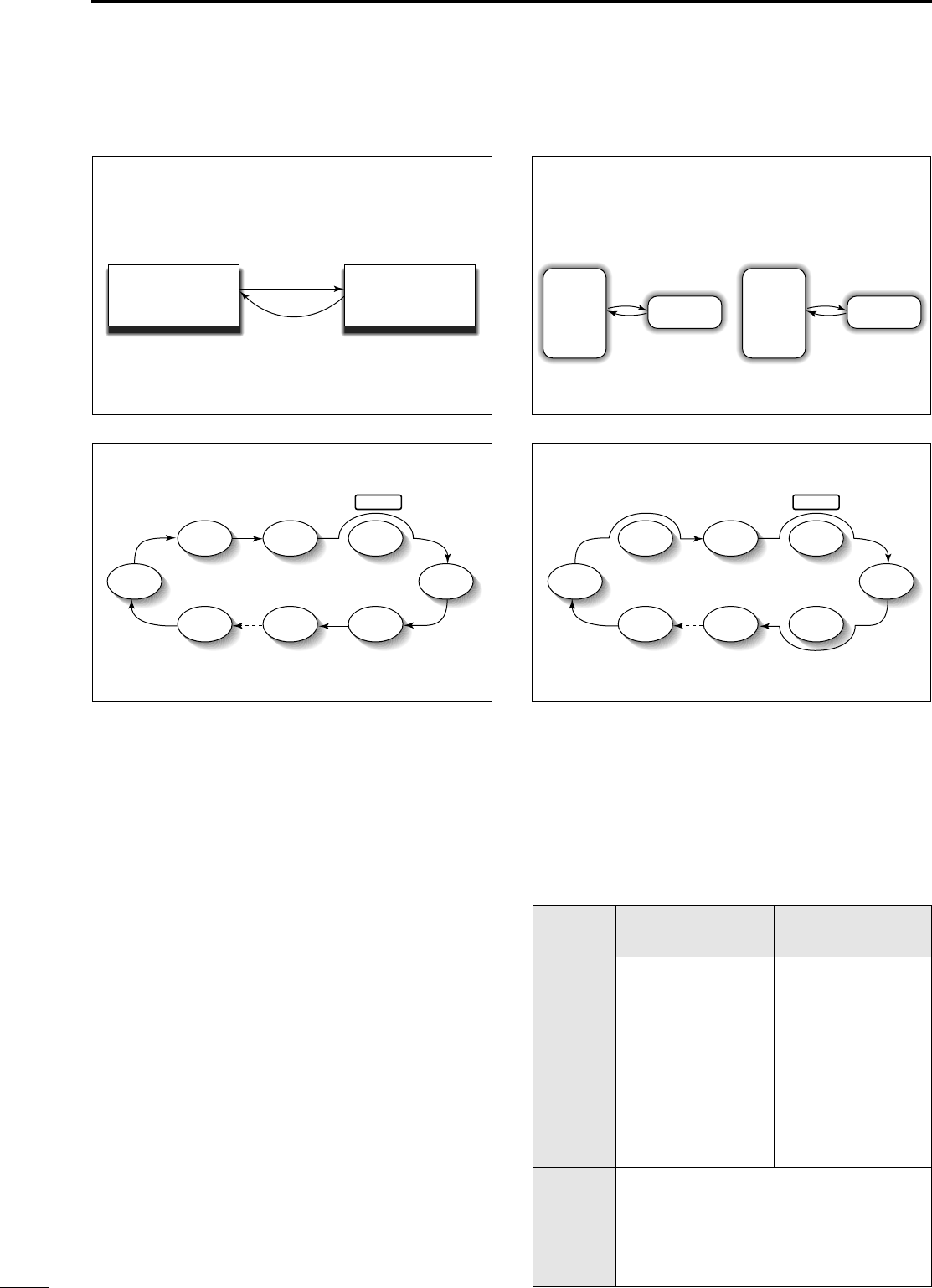
43
5MEMORY AND SCAN OPERATION
■SSccaann ttyyppeess
■PPrreeppaarraattiioonn
•CChhaannnneellss
For programmed scan: Program scan edge frequen-
cies into scan edge memory channels 1A and 1B
(p. 34).
For memory scan: Program 2 or more memory chan-
nels except scan edge memory channels.
For memory select scan: Designate 2 or more memory
channels as select memory channels—select a mem-
ory channel, then push [(F-2)SEL] in the S2 display
(memory mode) to designate the channel as a select
memory channel.
For priority watch: Program 1 memory channel to be
watched.
•SSccaann rreessuummee OONN//OOFFFF
You can select the scan to resume or cancel when
detecting a signal, in initial set mode, item 21. Scan
resume ON/OFF must be set before operating a scan.
See p. 53 for ON/OFF setting and scan resume con-
dition details.
•SSccaann ssppeeeedd
Scan speed can be selected from 2 levels, high or low,
in initial set mode. See p. 47 for details.
•SSqquueellcchh ccoonnddiittiioonn
PROGRAMMED SCAN
Repeatedly scans between two scan edge frequencies
(scan edge memory channels 1A and 1B).
This scan operates in VFO mode.
SELECTED MEMORY SCAN
Repeatedly scans all selected memory channels.
PRIORITY WATCH
Checks for signals on a memory or call channel while
operating on a VFO frequency.
This scan operates in memory mode.This scan operates in memory mode.
This scan operates in VFO mode.
Scan
Scan edge 1A or 1B Scan edge 1B or 1A
Jump
Mch 1 Mch 5
Memory channel watch Call channel watch
Memory
channel
VFO
frequency
Mch 2 Mch 3 Mch 4
Mch 6Mch 7Mch 99
MEMORY SCAN
Repeatedly scans all programmed memory channels.
Mch 1 Mch 5
Mch 2 Mch 3 Mch 4
Mch 6Mch 7Mch 99
BLANK
S (select)
S (select)S (select)
S (select) S (select)
S (select)
S (select)S (select)
S (select) S (select)
BLANK
Call
channel
VFO
frequency
SSCCAANN
SSTTAARRTTSS
WWIITTHH
PPRROOGGRRAAMMMMEEDD
SSCCAANN
MMEEMMOORRYY SSCCAANNSS
PPRRIIOORRIITTYY
WWAATTCCHH
SSQQUUEELLCCHH
OOPPEENN
The scan continues
until it is stopped
manually, and does
not pause even if it
detects signals.
This is not applicable
when the scan
resume is OFF and a
programmable step
(more than 1 kHz) is
selected.
Scan pauses on each
channel when the
scan resume is ON;
not applicable when
OFF.
SSQQUUEELLCCHH
CCLLOOSSEEDD
Scan stops when detecting a signal.
If you set scan resume ON in initial set mode,
the scan pauses for 10 sec. when detecting a
signal, then resumes. When a signal disap-
pears while scan is paused, scan resumes 2
sec. later.
IC-706MKIIG.qxd 02.3.27 13:53 Page 43
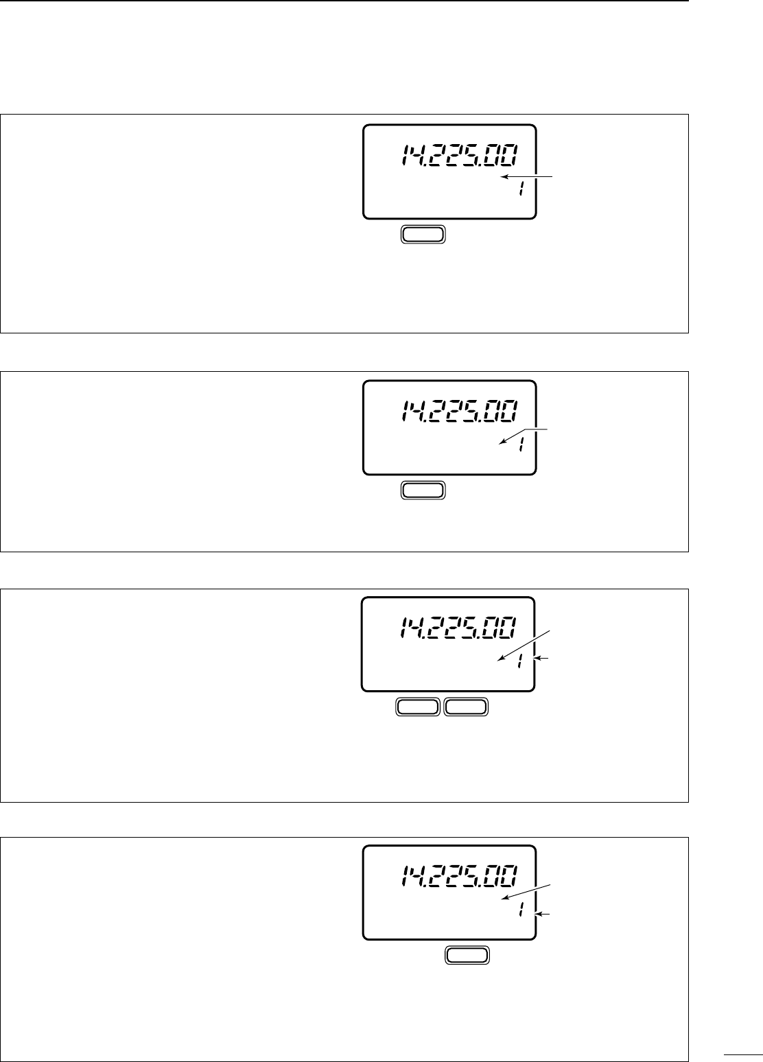
44
5
MEMORY AND SCAN OPERATION
➀Select VFO mode, then set a frequency.
➁Close the squelch with [SQL].
➂Set the desired memory channel as the watching
channel.
➃Select S2, then push [(F-2)PRI] to start the watch.
•Decimal point blinks while scanning.
➄When the scan detects a signal, the scan pauses
for 10 sec. or until the signal disappears, depend-
ing on the resume setting.
➅To cancel the scan push [(F-2)PRI]. NNoottee::The paused condition when detecting a signal
differs depending on the scan resume condition.
resume on: pauses for 10 sec.
resume off: pauses until the signal disappears.
➀Select memory mode.
➁Close the squelch with [SQL].
➂Select S2, then push [(F-1)SCN] to start the mem-
ory scan.
•Decimal point blinks while scanning.
➃Push [(F-2)SEL] to change the memory scan to
select memory scan.
•Push [(F-2)SEL] for 2 sec. to clear all select memory
channels.
➄When the scan detects a signal, the scan stops or
pauses depending on the resume setting.
➅To cancel the scan push [(F-1)SCN].
NNoottee::Two or more memory channels must be desig-
nated as select memory channels for select memory
scan to start.
S2 SCN SEL V/M
Select
memory mode
Designate
“S.”
F-1 F-2
Push [(F-1)SCN], then [(F-2)SEL].
CH
S
MEMO
PO
S1
5
53792040
10
60dB
USB
➀Select memory mode.
➁Close the squelch with [SQL].
➂Select S2, then push [(F-1)SCN] to start the scan.
•Decimal point blinks while scanning.
➃When the scan detects a signal, the scan stops or
pauses depending on the resume setting.
➄To cancel the scan push [(F-1)SCN].
NNoottee::Two or more memory channels must be pro-
grammed for memory scan to start.
S2 SCN SEL V/M
Select
memory mode
F-1 then push [(F-1)SCN]
CH
MEMO
PO
S1
5
53792040
10
60dB
USB
➀Select VFO mode.
➁Select the desired operating mode.
•The operating mode can also be changed while scan-
ning.
➂Set [SQL] open or closed.
•See page a left for squelch condition.
➃Select S2, then push [(F-1)SCN] to start the scan.
•Decimal point blinks while scanning.
➄When the scan detects a signal, the scan turns
OFF, pauses or ignores it depending on the
resume setting and the squelch condition.
•During scan [TS] can be used only when resume is ON.
➅To cancel the scan push [(F-1)SCN].
NNoottee::If the same frequencies are programmed into
the scan edge memory channels 1A and 1B, pro-
grammed scan does not start.
■PPrrooggrraammmmeedd ssccaann ooppeerraattiioonn
■MMeemmoorryy ssccaann ooppeerraattiioonn
■SSeelleecctt mmeemmoorryy ssccaann ooppeerraattiioonn
S2 SCN PRI V/M
Select
VFO mode
Select watching
channel
F-2 Push [(F-2)PRI].
CH
PO
S1
5
53792040
10
60dB
USB
VFO A
■PPrriioorriittyy wwaattcchh
CH
VFO A
PO
S1
5
53792040
10
60dB
USB
S2 SCN PRI V/M
Select
VFO mode
F-1 then push [(F-1)SCN]
IC-706MKIIG.qxd 02.3.27 13:53 Page 44
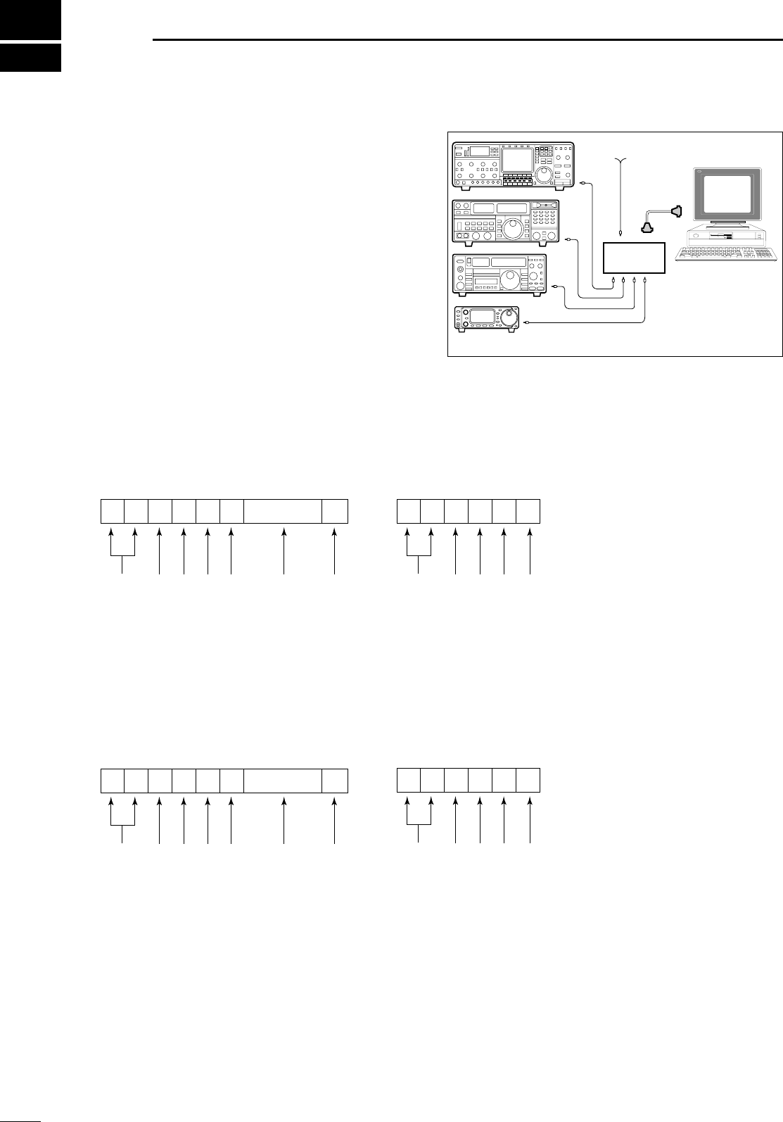
45
6RREEMMOOTTEE JJAACCKK ((CCII--VV)) IINNFFOORRMMAATTIIOONN
CONTROLLER TO IC-706MKIIG
FE FE 58 E0 Cn Sc Data area FD
Preamble code (fixed)
Transceiver’s default address
Controller’s default address
Command number
(see table at right)
Sub command number
(see table at right)
BCD code data for frequency or
memory number entry
End of message code (fixed)
OK MESSAGE TO CONTROLLER
FE FE 58 E0 FB FD
Preamble code (fixed)
Transceiver’s default address
Controller’s default address
OK code (fixed)
End of message code (fixed)
NG MESSAGE TO CONTROLLER
FE FE 58 E0 FA FD
Preamble code (fixed)
Transceiver’s default address
Controller’s default address
NG code (fixed)
End of message code (fixed)
IC-706MKIIG TO CONTROLLER
FE FE E0 58 Cn Sc Data area FD
Preamble code (fixed)
Controller’s default address
Transceiver’s default address
Command number
(see table at right)
Sub command number
(see table at right)
BCD code data for frequency or
memory number entry
End of message code (fixed)
DCCII--VV ccoonnnneeccttiioonn eexxaammppllee
The transceiver can be connected through an option-
al CT-17
CI
-
V LEVEL CONVERTER
to a personal computer
equipped with an RS-232C port. The Icom
Communication interface-V (CI-V) controls the follow-
ing functions of the transceiver.
Up to four Icom CI-V transceivers or receivers can be
connected to a personal computer equipped with an
RS-232C port. See p. 55 for setting the CI-V condi-
tion using initial set mode.
DDDaattaa ffoorrmmaatt
The CI-V system can be operated using the following
data formats. Data formats differ according to com-
mand numbers. A data area is added for some com-
mands.
Personal
computer
IC-706MKIIG
CT-17
9–15 V DC
IC-706MKIIG.qxd 02.3.27 13:53 Page 45
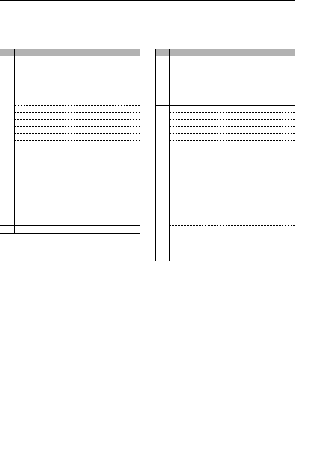
46
6
REMOTE JACK (CI-V) INFORMATION
*
1
When wide or normal operation is available, add “00” for wide operation
or “01” for normal operation; when normal or narrow operation is avail-
able, add “00” for normal operation or “01” for narrow operation; when
wide, normal and narrow operation is available, add “00” for wide oper-
ation, “01” for normal operation and “02” for narrow operation.
*2Memory channel number 1A=0100/1b=0101, 2A=0102/2b=0103,
3A=0104/3b=0105, C1=0106, C2=0107.
CCOOMMMMAANNDD TTAABBLLEE
CCnnSSccDDeessccrriippttiioonn
00 —Send frequency data
01 x x Send mode data
02 —Read band edge frequencies
03 —Read display frequency
04 —Read display mode
05 —Set frequency data
00*1Set LSB
01*1Set USB
02*1Set AM
06 03*1Set CW
04*1Set RTTY
05*1Set FM
06*1Set WFM
—Set to VFO
00 Set to VFO A
07 01 Set to VFO B
A0 VFO A=B
B0 Switch VFO A and B
08 —Set to memory mode
mc*2Mch
09 —Memory write
0A —Memory to VFO
0B —Memory clear
0C —Read duplex offset frequency
0D —Set duplex offset frequency
CCnnSSccDDeessccrriippttiioonn
0E 00 Scan stop
01 Scan start
00 Split OFF
01 Split ON
0F 10 Simplex mode
11 Duplex mode
12 Duplex + mode
00 10 Hz TS
01 100 Hz TS
02 1 kHz TS
03 5 kHz TS
04 9 kHz TS
10 05 10 kHz TS
06 12.5 kHz TS
07 20 kHz TS
08 25 kHz TS
09 100 kHz TS
11 x x ATT ON/OFF; 00=OFF; 20=ON
15 01 Read squelch condition
02 Read S-meter level
02 Preamp setting
12 AGC setting
16 22 NB setting
42 TONE setting
43 TSQL setting
44 COMP setting
46 VOX setting
47 BK-IN setting
19 00 Read transceiver ID code
IC-706MKIIG.qxd 02.3.27 13:53 Page 46
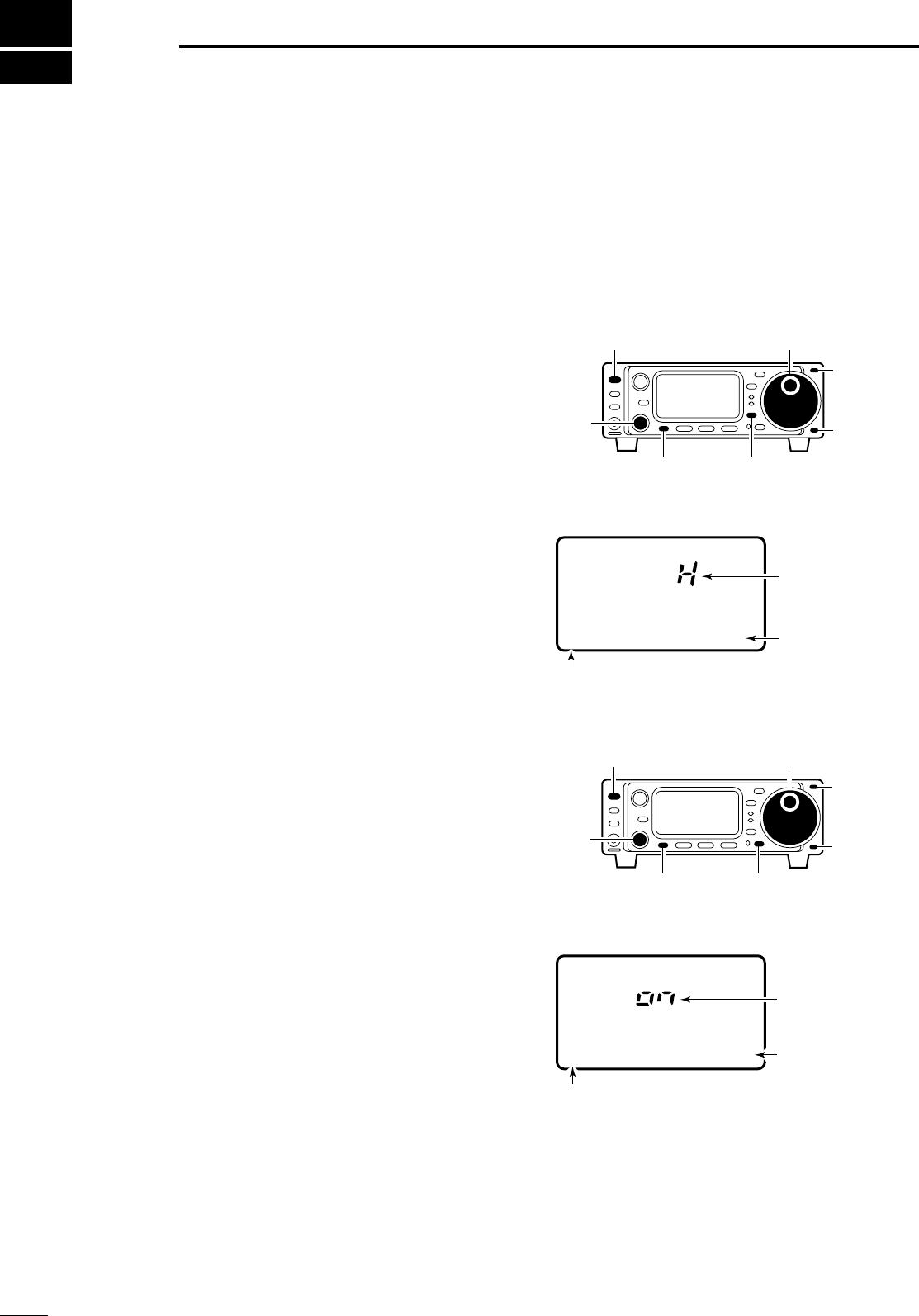
47
7SSEETT MMOODDEE
■GGeenneerraall
Set mode is used for programming infrequently
changed values or conditions of functions. The IC-
706MKIIG has 2 separate set modes: quick set mode
and initial set mode.
DQQuuiicckk sseett mmooddee ooppeerraattiioonn
➀While power is ON, push [DISPLAY] for 2 sec.
•Quick set mode is selected and one of its items appears.
•Quick set mode items vary depending on the operating
mode (SSB, FM, etc.) selected.
➁Push [MENU] one or more times to select the
desired item.
•[M-CH] or [Y]/[Z] can also be used.
➂Rotate the main dial to set the values or conditions
for the selected item.
➃Repeat steps ➁and ➂to set other items.
➄To exit quick set mode, push [DISPLAY] momentar-
ily.
DIInniittiiaall sseett mmooddee ooppeerraattiioonn
➀Push [POWER] for 2 sec. to turn power OFF.
➁While pushing [LOCK] push [POWER] to turn
power ON.
•Initial set mode is selected and one of its items appears.
➂Push [MENU] one or more times to select the
desired item.
•[M-CH] or [Y]/[Z] can also be used.
➃Rotate the main dial to set the values or conditions
for the selected item.
➄Repeat steps ➂and ➃to set other items.
➅To exit initial set mode, push [POWER] for 2 sec. to
turn power OFF.
➆Push [POWER] to turn power ON again.
•The conditions selected in initial set mode are now effec-
tive.
[POWER]
[MENU] [LOCK]
Main dial
Item number
Item
Value or
condition
1 MODE SELECT
[DISPLAY EXAMPLE: INITIAL SET MODE]
[M-CH]
[Y]
[Z]
Q1 RF POWER
USB
[POWER]
[MENU]
[M-CH]
[DISPLAY]
Main dial
[Y]
[Z]
Item number
Item
Value or
condition
[DISPLAY EXAMPLE: QUICK SET MODE]
PO
S1
5
53792040
10
60dB
IC-706MKIIG.qxd 02.3.27 13:53 Page 47
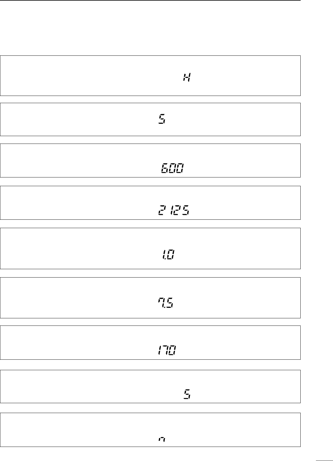
48
7
SET MODE
Q4 RTTY KEYING ((RRTTTTYY oonnllyy))
This item adjusts the RTTY keying. Normal or reverse
keying can be selected.
The default is “n,” normal.
Normal : key open=mark
Reverse : key open=space
R
TT
Y
■QQuuiicckk sseett mmooddee iitteemmss
Q1 RF POWER ((aallll mmooddeess))
This item adjusts the RF output power. The RF out-
put power can be adjusted from L, 1 to 9 and H for
indication, however, it can be adjusted continuously.
Q2 MIC GAIN ((SSSSBB//AAMM//FFMM oonnllyy))
This item adjusts microphone gain from 1 to 10 for
indication, however, it can be adjusted continuously.
The default is 5.
Note that while adjusting mic gain, the
ALC meter is displayed automatically.
The default is H (maximum power).
Note that while adjusting the output
power, the power meter is displayed
automatically.
Q2 CW PITCH ((CCWW oonnllyy))
This item adjusts the CW pitch. CW pitch is adjustable
from 300 to 900 Hz in 10 Hz steps. The default is 600 Hz.
CW
Q2 RTTY TONE ((RRTTTTYY oonnllyy))
This item selects the RTTY tone. RTTY tone is tog-
gled between 1275, 1615 and 2125 Hz. The default is 2125 Hz.
R
TT
Y
Q3 VOX DELAY ((SSSSBB//AAMM//FFMM oonnllyy))
This item adjusts the VOX (Voice-activated Transmit)
delay time. The delay time can be adjusted from 0 to
2 sec. in 0.1 sec. units.
The default is 1.0 seconds.
USB
Q3 BK-IN DELAY ((CCWW oonnllyy))
This item adjusts break-in delay time for CW semi
break-in operation. The delay time is selectable from
2.0 to 13.0 (dots).
The default is 7.5 dots.
CW
Q3 RTTY SHIFT ((RRTTTTYY oonnllyy))
This item adjusts the RTTY shift. There are 3 selec-
table values: 170, 200 and 425 Hz. The default is 170 Hz.
R
TT
Y
Q4 VOX GAIN ((SSSSBB//AAMM//FFMM oonnllyy))
This item adjusts the VOX gain for the VOX (voice acti-
vated transmit) function.
USB
The default is 5.
IC-706MKIIG.qxd 02.3.27 13:53 Page 48
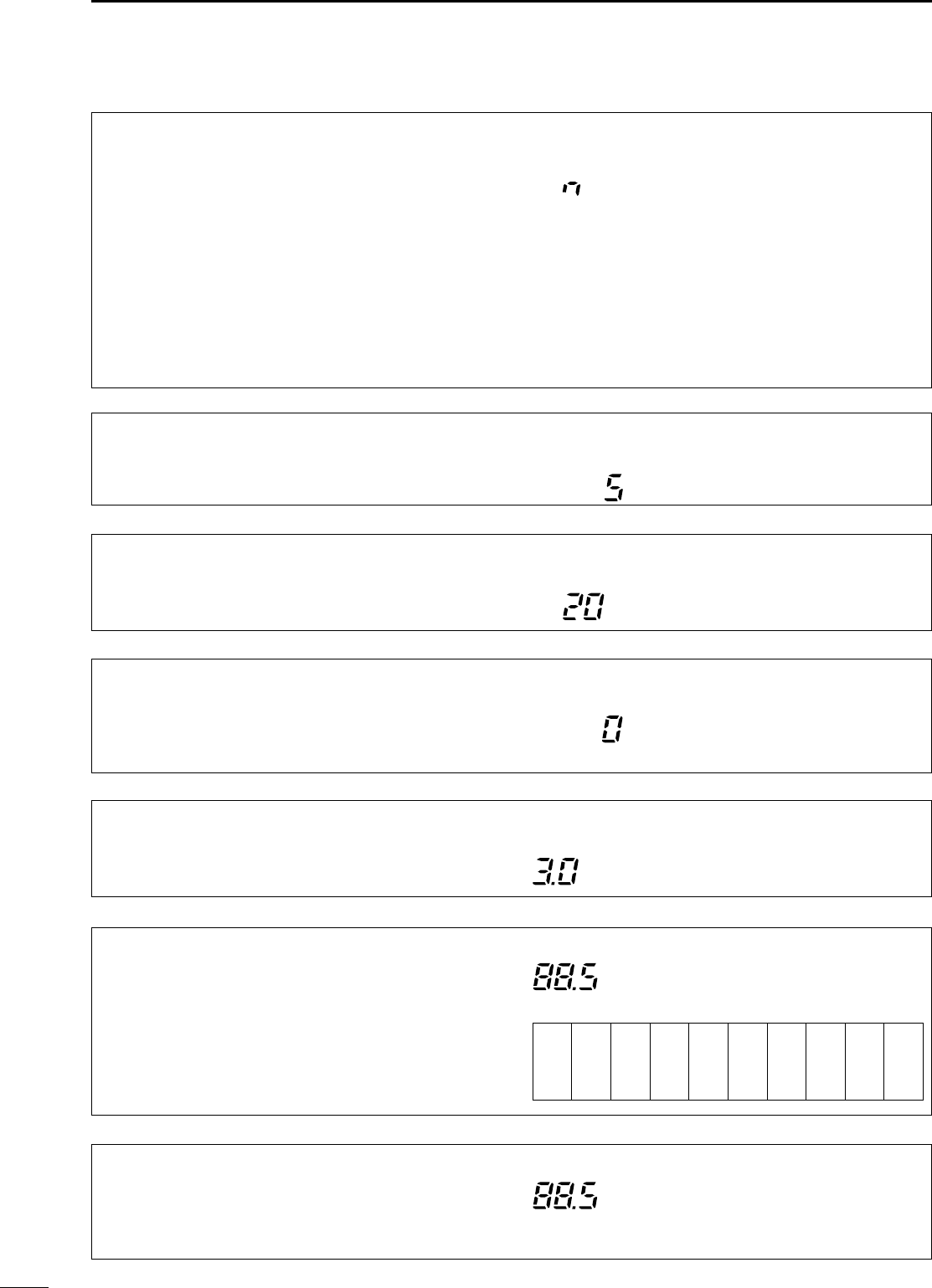
49
7SET MODE
Q6 CARRIER Frq ((SSSSBB oonnllyy))
This item adjusts the carrier frequency (BFO frequen-
cy), allowing you to change the audio characteristics.
Selectable values are –200 to +200 Hz in 10 Hz steps.
USB
The default is 0 Hz.
Q6 RPTR TONE ((FFMM oonnllyy))
This item selects a subaudible tone for FM-T mode
operation to access a repeater. There are 50 tones
available from 67.0 Hz to 254.1 Hz (see table at right). •Available subaudible tones Unit: Hz
The default is 88.5 Hz.
FM
Q4 CW PADDLE ((CCWW oonnllyy))
This item adjusts the CW paddle type. Four selec-
tions are available.
•n : normal (for electronic keyer use)
•r : reverse (for electronic keyer use)
•buG : When using the electronic key, key down
produces a “dash,” releasing the key
automatically produces a “dot(s).”
•oFF : Turns OFF the electronic keyer (for
straight key use)
•ud : For using the microphone’s [UP]/[DN]
keys instead of the CW paddle.
The default is “n,” normal.
CW
Q5 KEY SPEED ((CCWW oonnllyy))
This item adjusts the CW key speed. The key speed
can be selected from 6 to 60 wpm. The default is 20 wpm.
CW
Q6 RATIO ((CCWW oonnllyy))
This item adjusts the CW key ratio (or weight). The
ratio can be selected from 2.8 to 4.5. The default is 3.0.
CW
Q7 TONE SQL ((FFMM oonnllyy))
This item adjusts sets a subaudible tone for tone
squelch use. (the same subaudible tone frequencies
as for repeater operation are available—see above).
The default is 88.5 Hz.
FM
67.0 79.9 94.8 110.9 131.8 156.7 171.3 186.2 203.5 229.1
69.3 82.5 97.4 114.8 136.5 159.8 173.8 189.9 206.5 233.6
71.9 85.4 100.0 118.8 141.3 162.2 177.3 192.8 210.7 241.8
74.4 88.5 103.5 123.0 146.2 165.5 179.9 196.6 218.1 250.3
77.0 91.5 107.2 127.3 151.4 167.9 183.5 199.5 225.7 254.1
Q5 ANTI VOX ((SSSSBB//AAMM//FFMM oonnllyy))
This item adjusts the ANTI-VOX gain for the VOX
(voice activated transmit) function.
USB
The default is 5.
IC-706MKIIG.qxd 02.3.27 13:53 Page 49
50
7
SET MODE
4 BACK LIGHT
((ddiissppllaayy bbaacckklliigghhttiinngg))
The function display backlighting can be set to high,
low or OFF to suit ambient lighting. Display backlighting set to
high (default).
Display backlighting set to
low.
5 KEY LIGHT
((kkeeyy//sswwiittcchh bbaacckklliigghhttiinngg))
The key/switch backlighting can be set to high, low or
OFF to suit ambient lighting. Display backlighting set to
high (default).
Display backlighting set to
low.
■IInniittiiaall sseett mmooddee iitteemmss
2 BEEP ((ccoonnffiirrmmaattiioonn bbeeeepp))
A beep sounds each time a switch is pushed to con-
firm it. This function can be turned OFF for silent
operation.
3 BAND BEEP ((bbaanndd bbeeeepp))
A beep sounds when an operating frequency enters or
exits a transmit frequency range. This functions inde-
pendent of the confirmation beep setting (above).
Confirmation beep ON
(default)
Confirmation beep OFF
Band beep ON
(default)
Band beep OFF
1 MODE SELECT ((aallll mmooddeess))
This item is available in all modes, and allows you to
simplify operation by inhibiting the selection of
unneeded operating modes during normal opera-
tion. For example if you are operating mobile and only
plan on using FM and AM modes, use “MODE
SELECT” to inhibit access to all other modes (SSB,
CW, RTTY, WFM), thereby making selection of AM or
FM quick and easy.
The default is on for all operating
modes. To toggle an operating mode
on or off, push (or push and hold)
[MODE] one or more times until the
desired mode is displayed, then rotate
the main dial to set on or off.
Q8 RPTR-T SCN
((rreeppeeaatteerr ttoonnee ssccaann))
During repeater operation, you can detect the tone
frequency necessary to open a repeater (see p. 30).
The default is 88.5 Hz.
FM
Q8 T-SQL SCN
((ttoonnee ssqquueellcchh ttoonnee ssccaann))
During tone squelch operation, you can detect the
tone frequency necessary to communicate using
tone squelch (see p. 31).
The default is 88.5 Hz.
FM
IC-706MKIIG.qxd 02.3.27 13:53 Page 50
51
SET MODE
7
11 PEAK HOLD ((ppeeaakk hhoolldd))
When the peak hold function is ON, the highest acti-
vated segment of the meter remains visible for 0.5
sec.; when OFF, the meter functions normally. Peak hold ON
(default)
Peak hold OFF
6 AUTO OFF ((aauuttoo ppoowweerr OOFFFF))
The auto power OFF function can be used to auto-
matically turn the transceiver OFF after a specified
time of operation. This item can be set to 30 min., 60
min., 90 min., 120 min., or OFF.
Auto power OFF set to
20 min.
Auto power OFF
deactivates. (default)
7 RF/SQL ((SSQQLL//AAUUTTOO//RRFF•SSQQLL))
The [RF/SQL] control can be set as the squelch con-
trol (default), the RF/squelch control (USA version
default) or automatic (acts as squelch in FM/WFM/AM
modes; as RF in SSB/CW/RTTY modes). (See p. 22)
NNoottee::RF gain does not function in WFM mode
The [RF/SQL] control
functions as RF gain
control only.
The [RF/SQL] control
functions as squelch
control only.
8 SUBDIAL ((SSuubbddiiaall ffuunnccttiioonn))
When this item is set to “rit,” pushing [RIT/SUB]
turns the RIT function ON (lights red)—rotating [M-
CH] changes the RIT frequency; when this item is set
to “Freq,” pushing [RIT/SUB] turns the sub dial func-
tion ON (lights green)—rotating [M-CH] changes the
operating frequency. Note that in FM, WFM and AM
modes, pushing [RIT/SUB] always selects the sub
dial function (lights green), regardless of this setting.
Pushing [RIT/SUB]
selects the RIT function
(default).
Pushing [RIT/SUB]
selects the sub dial function.
9 OPT. FIL 1 ((ooppttiioonnaall ffiilltteerr))
When an optional filter is installed, this selection is
necessary, otherwise the filters cannot be selected.
Selections available are FL-100, FL-101, FL-103,
FL-223, FL-232 and none (default). See p. 22 for
usable filters for each mode and see p. 60 for filter
installation.
10 OPT. FIL 2 ((ooppttiioonnaall ffiilltteerr))
When an optional filter is installed, this selection is
necessary, otherwise the filters cannot be selected.
Selections available are FL-100, FL-101, FL-103,
FL-223, FL-232 and none (default). See p. 22 for
usable filters for each mode and see p. 60 for filter
installation.
No filters are selected
(default).
FL-223 (for LSB/USB mode)
is selected.
No filters are selected
(default).
FL-223 (for LSB/USB mode)
is selected.
IC-706MKIIG.qxd 02.3.27 13:53 Page 51
52
15 DUP HF ((dduupplleexx ooffffsseett))
This item sets the offset for the duplex function
when operating on the HF bands.
Default is 0.100 MHz.
16 DUP 50M ((dduupplleexx ooffffsseett))
This item sets the offset for the duplex function
when operating on the 50 MHz band. Default is 0.500 MHz.
17 DUP 144M ((dduupplleexx ooffffsseett))
This item sets the offset for the duplex function
when operating on the 144 MHz band. Default is 0.600 MHz.
18 DUP 430M ((dduupplleexx ooffffsseett))
This item sets the offset for the duplex function
when operating on the 430 MHz band. Default is 5.000 MHz.
19 1TOUCH RPTR
((oonnee ttoouucchh rreeppeeaatteerr))
This item sets the offset direction when using the
one-touch repeater function. +duplex or –duplex
can be selected. Duplex direction is set
to –duplex.
Duplex direction is set to
+duplex.
DUP DUP
14 SPL OFFSET ((sspplliitt ooffffsseett))
This item sets the offset (difference between transmit
and receive frequencies) for the quick split function.
Note that this setting is not valid in FM/WFM modes.
Default is 0.100 MHz.
13 SPLIT LOCK ((sspplliitt lloocckk))
When this item is ON the main dial can be used to
adjust the transmit frequency (XFC) even while the
lock function is activated. Split lock function OFF
(default)
Split lock function ON
12 QUICK SPLIT
((qquuiicckk sspplliitt ffuunnccttiioonn))
When this item is set to ON, pushing [SPL] for 2 sec.
sets the undisplayed VFO frequency to the dis-
played VFO frequency plus the split offset or duplex
offset, and activates split operation.
Quick split function ON
(default).
Quick split function OFF.
7
SET MODE
IC-706MKIIG.qxd 02.3.27 13:53 Page 52
53
SET MODE
7
26 PWR ON CHK ((PPoowweerr oonn cchheecckk))
When this item is set to “on,” the set output power is
briefly displayed when turning power ON (RIT and
auto power off settings are also displayed if activat-
ed); when turned “oFF,” the display goes directly to
frequency indication at power ON.
Power on check ON
(default)
Power on check OFF
24 AM NB ((NNooiissee bbllaannkkeerr iinn AAMM mmooddee))
When this item is set to ON, the noise blanker func-
tion is available in AM mode. This is useful when com-
municating in AM mode (the noise blanker function
should not be used when listening to regular AM
broadcasts as it may degrade the received audio).
Noise blanker available
(default)
Noise blanker not available
20 AUTO RPTR ((aauuttoo rreeppeeaatteerr))
When this item is set to “on 1”, the tone encoder is
not set when the auto repeater is activated; when set
to “on 2” the auto repeater function also sets the
tone encoder on.
Auto repeater function OFF
(default).
Auto repeater function ON,
tone encoder OFF.
22 SCAN SPEED ((ssccaann ssppeeeedd))
This item sets the rate at which channels or frequen-
cies are scanned during scan operations. High or low
can be selected.
23 U/D SPEED ((uupp//ddoowwnn ssppeeeedd))
This item sets the rate at which frequencies are
scanned through when the [UP]/[DN] switches are
pushed and held. High or low can be selected.
Scan speed is set to high
(default).
Scan speed is set to low.
Up/down speed is set to
high (default).
Up/down speed is set to low.
21 SCAN RESUME ((ssccaann rreessuummee))
This item sets the scan resume function ON or OFF.
ON: scan resumes 10 sec. after stopping on a signal
(or 2 sec. after a signal disappears); OFF: scan does
not resume after stopping on a signal. For the priority
watch, setting to OFF pauses the watch until signal
disappears and scan resumes.
Scan resume function is
turned ON (default).
Scan resume function is
turned OFF.
25 PAD CH ((aavvaaiillaabbllee mmeemmoo ppaaddss))
This item sets the number of memo pad channels
available. 5 or 10 memo pads can be set. 5 memo pads are available
(default).
10 memo pads are available.
IC-706MKIIG.qxd 02.3.27 13:53 Page 53
54
29 9600 MODE
((DDaattaa ssoocckkeett ssppeeeedd))
This is used to change the communications speed
packet operation. The data socket can be set to
1200 or 9600 baud. Default is 9600 baud.
30 VSEND SEL
((AACCCC ssoocckkeett oouuttppuutt))
“on”: VSEND is for 144/430 MHz; HSEND is for
the HF/50 MHz
“U only”: VSEND is for 430 MHz; HSEND is for
HF/50/144 MHz
“oFF”: VSEND is not used; HSEND is for all bands.
The default is VSEND is for the 144/430 MHz band;
HSEND is for the HF/50 MHz band.
31 SPEECH LANG
When the optional UT-102
VOICE SYNTHESIZER UNIT
is
installed, you can select between English and
Japanese as the language.
32 SPEECH SPD
When the optional UT-102
VOICE SYNTHESIZER UNIT
is
installed, you can select between faster or slower
synthesizer output.
Voice synthesizer functions
in English (default).
Voice synthesizer functions
in Japanese.
Voice synthesizer output
is faster (default).
Voice synthesizer output
is slower.
((vvooiiccee ssyynntthheessiizzeerr llaanngguuaaggee))
((vvooiiccee ssyynntthheessiizzeerr ssppeeeedd))
28 PTT TUNE
((PPTTTT ttuunnee ffuunnccttiioonn))
When an optional AH-4
ANTENNA TUNER
is connect-
ed, tuning can be started automatically at the
moment the PTT is pushed.
27 A-TUNE STRT
((aauuttoo ttuunneerr ssttaarrtt))
The optional AT-180
ANTENNA TUNER
has an automat-
ic start capability which starts tuning if the SWR is
higher than 1.5–3.
When “oFF” is selected, the tuner remains OFF
even when the SWR is poor (1.5–3).
When “on” is selected, automatic tune starts even
when the tuner is turned OFF.
NNoottee::Even when “on” is selected, automatic tune
does not start for the 50 MHz band.
Auto tune function OFF
(default).
Auto tune function ON.
Tuning starts when pushing [PTT]
on a new frequency.
Tuning starts only when
[TUNER] is pushed
(default)
.
7
SET MODE
IC-706MKIIG.qxd 02.3.27 13:53 Page 54
55
7SET MODE
33 S-LVL SPCH ((SS--lleevveell ssppeeeecchh))
When an optional UT-102
SPEECH SYNTHESIZER UNIT
is installed, the synthesizer can be set to read out the
frequency/mode only, or both the frequency/mode
and S-meter level.
Voice synthesizer reads out
both the frequency/mode
and S-meter level (default).
Voice synthesizer reads out
the frequency/mode only.
37 CI-V 731 ((CCII--VV ooppeerraattiinngg ffrree--
qquueennccyy ddaattaa lleennggtthh))
When connecting the IC-706MKIIG to the IC-735 for
transceive operation, you must change the operat-
ing frequency data length to 4 bytes.
•This item
MUST
be set to “on” only when operating trans-
ceiver with the IC-735.
Frequency data set to
5 bytes (default).
Frequency data set to
4 bytes.
36 CI-V TRN ((CCII--VV ttrraannsscceeiivvee))
Transceive operation is possible with the IC-
706MKIIG connected to other Icom HF transceivers
or receivers. When “on” is selected, changing the
frequency, operating mode, etc. on the IC-706MKIIG
automatically changes those of connected trans-
ceivers (or receivers) and vice versa.
Transceive ON
(default)
Transceive OFF
34 CI-V ADDRES ((CCII--VV aaddddrreessss))
To distinguish equipment, each CI-V transceiver has
its own Icom standard address in hexadecimal code.
The IC-706MKIIG’s address is 4EH.
When 2 or more IC-706MKIIG’s are connected to an
optional CT-17
CI
-
V LEVEL CONVERTER
, rotate the
main dial to select a different address for each IC-
706MKIIG in the range 01H to 7FH.
35 CI-V BAUD ((CCII--VV ddaattaa rraattee))
This item sets the data transfer rate. When “Auto” is
selected, the baud rate is automatically set according
to the connected controller or remote controller.
Address set to 58H
(default).
Address set to 7FH.
Auto baud rate
(default)
19200 bps
IC-706MKIIG.qxd 02.3.27 13:53 Page 55
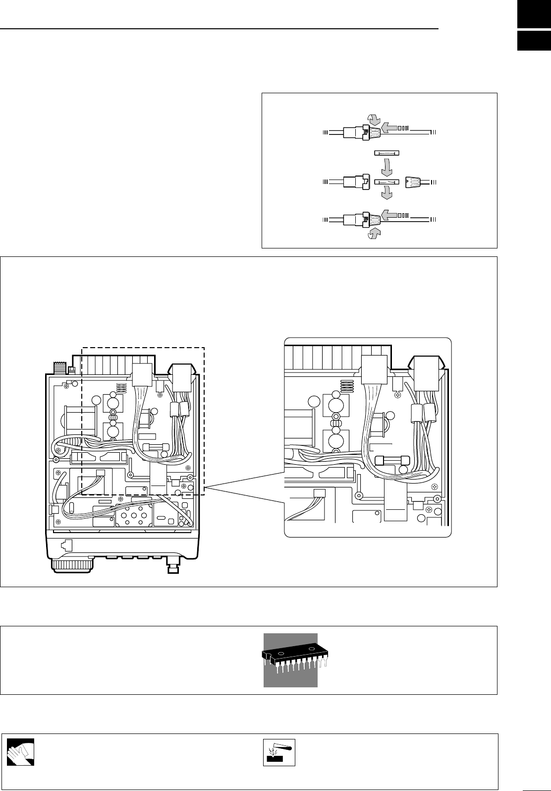
56
8
MMAAIINNTTEENNAANNCCEE
If the transceiver becomes dusty or dirty,
wipe it clean with a dry, soft cloth.
AAVVOOIIDDthe use of strong chemical solvents
such as thinner, benzine or alcohol to clean
the transceiver. These may damage the
transceiver’s surfaces.
■FFuussee rreeppllaacceemmeenntt
If a fuse blows or the transceiver stops functioning, try
to find the source of the problem, and replace the
damaged fuse with a new, rated fuse.
CCaauuttiioonn:: DDiissccoonnnneecctt the DC power cable from the
transceiver when changing a fuse.
The IC-706MKIIG has 2 types of fuses installed for
transceiver protection.
•DC power cable fuses .................................... 30 A
•Circuitry fuse ............................ F.G.M.B. 125 V 4 A
DDCC PPOOWWEERR CCAABBLLEE FFUUSSEE RREEPPLLAACCEEMMEENNTT
30 A fuse
CCIIRRCCUUIITTRRYY FFUUSSEE RREEPPLLAACCEEMMEENNTT
The 13.8 V DC from the DC power cable is applied to
all units in the IC-706MKIIG, except for the power
amplifier, through the circuitry fuse. This fuse is
installed in the PA unit.
■MMeemmoorryy bbaacckkuupp
All of the CPU’s memory is backed up by an EEP-
ROM (Electronically-Erasable Programmable Read-
Only Memory). All data you set, such as VFO, memo-
ry, set mode contents, etc. is stored in this EEPROM.
There is no internal lithium battery.
■CClleeaanniinngg
4 A Fuse
IC-706MKIIG.qxd 02.3.27 13:53 Page 56

57
9TTRROOUUBBLLEESSHHOOOOTTIINNGG
The following chart is designed to help you correct
problems which are not equipment malfunctions.
If you are unable to locate the cause of a problem or
solve it through the use of this chart, contact your
nearest Icom Dealer or Service Center.
PROBLEM
POWER SUPPLY
RECEIVE
POSSIBLE CAUSE SOLUTION REF.
Power does not come
on when the [POWER]
switch is pushed.
No sound comes from
the speaker.
Sensitivity is low.
Receive audio is distor-
ted.
Receive signal is distor-
ted with strong signals.
DC power cable is improperly
connected.
Fuse is blown.
Battery is exhausted if you are using
a 12 V battery as the power source.
Reconnect the power cable correctly.
Check for the cause, then replace the
fuse with a spare one.
(Fuses are installed in two places. One is
installed in the DC power cable and the
other is installed in the PA unit.
Check the battery voltage with the
[POWER] pushed IN.
p. 13
p. 56
—
p. 1
p. 1
—
p. 12
p. 12
—
—
p. 14
pgs. 27,
28
p. 21
p. 19
p. 20
p. 21
p. 21
Volume level is set too low.
The squelch is closed.
The transceiver is in the transmitting
condition.
An external speaker or headphones
are connected.
The antenna is not connected properly.
The antenna feed line is cut or shorted.
The antenna for another band is
selected.
The antenna is not properly tuned.
The attenuator function is activated.
The operating mode is not selected
correctly.
The [SHIFT] control is set off-center.
Noise blanker function is activated.
Preamp is activated.
Rotate [AF] clockwise to obtain a suit-
able listening level.
Rotate [SQL] counterclockwise to
open the squelch.
Release [PTT] on the microphone or
check the SEND line of an external
unit, if connected.
Check the external speaker or head-
phone plug connection.
Check the speaker ON/OFF switch or
speaker A/B switch, when an optional
SP-20 EXTERNAL SPEAKER is in use.
Reconnect to the antenna connector.
Check the feed line and correct any
improper conditions.
Select an antenna suitable for the
operating frequency.
Make sure that [ANT1] is used for
frequencies less than 60 MHz and
[ANT2] is used for frequencies of 60
MHz and above.
Push [TUNE] to manually tune the
antenna.
Push [ATT] to turn the function OFF.
Select a suitable operating mode.
Set [SHIFT] to the center position.
Push [NB] to turn the function OFF.
Push [P.AMP] to turn the function
OFF.
IC-706MKIIG.qxd 02.3.27 13:53 Page 57

58
9
TROUBLESHOOTING
PROBLEM
TRANSMITDISPLAYSCAN
POSSIBLE CAUSE SOLUTION REF.
Transmitting is impossi-
ble.
Output power is too low.
No contact possible with
other stations.
Repeater cannot be ac-
cessed.
Transmitted signals are
distorted.
Displayed frequency
does not change proper-
ly.
Programmed scan does
not stop.
Programmed scan does
not start.
Memory scan does not
start.
Memory select scan
does not start.
The operating frequency is not set to
a ham band.
Power is set to a lower power than
maximum.
Microphone gain is set too low.
The antenna is not connected properly.
The antenna feed line is cut or shorted.
An antenna for another band is selec-
ted.
The antenna is not properly tuned.
RIT function is activated.
Split function is activated.
Split function is not activated.
An incorrect transmit frequency is set.
Subaudible tone encoder is OFF and
repeater requires a tone for access.
Programmed subaudible tone fre-
quency is wrong.
Microphone gain is set too high.
[COMP LEVEL] is rotated too far
clockwise with the speech compres-
sor ON.
The dial lock function is activated.
The internal CPU has malfunctioned.
Squelch is open.
The same frequencies have been
programmed in scan edge memory
channels.
2 or more memory channels have not
been programmed.
2 or more memory channels have not
been designated as select channels.
Set squelch to the threshold position.
Programm different frequencies into
scan edge memory channels.
Program 2 or more memory chan-
nels.
Designate 2 or more memory chan-
nels as select channels for the scan.
Set gain in quick set mode.
Set [COMP LEVEL] to a suitable pos-
ition.
Push [LOCK] to deactivate the func-
tion.
Reset the CPU.
(While pushing [UP] and [DN] push [POW-
ER] to turn power ON.
Push [DUP] to turn the function ON
.
Set the proper frequencies into VFO
A and B or into one of the memory
channels.
Use [TON] to select FM-T.
Program the required frequency using
quick set mode.
Push RIT to turn the function OFF.
Push [SPLIT] to turn the function OFF.
Set the output power in quick set
mode.
Set microphone gain to a suitable
position using quick set mode.
Reconnect the antenna connector.
Check the feed line and correct any
improper conditions.
Select an antenna suitable for the op-
erating frequency.
Push [TUNE] to manually tune the
antenna when an optional antennal
tuner is connected.
Set the frequency to a ham band. p. 17
p. 44
p. 44
—
—
p. 14
pgs. 27,
28
p. 20
p. 29
p. 29
p. 17
p. 30
p. 49
p. 48
p. 5
p. 2
p. 15
p. 23
p. 44
p. 41
p. 44
IC-706MKIIG.qxd 02.3.27 13:53 Page 58
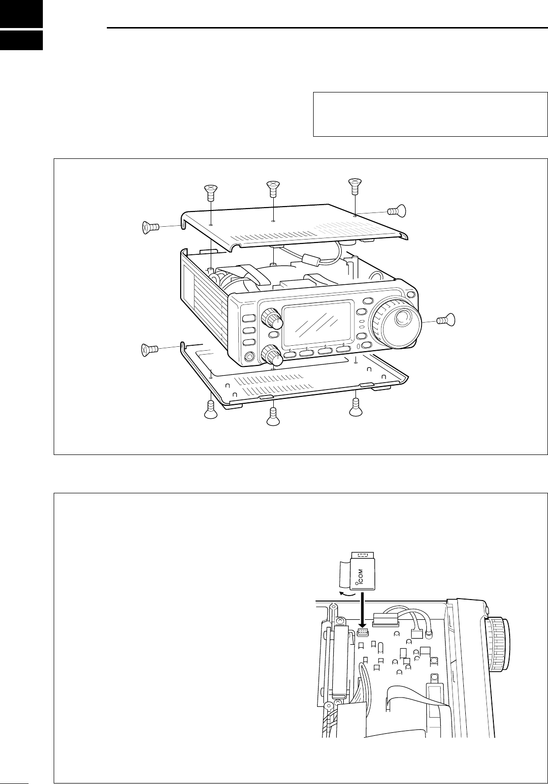
59
10 OOPPTTIIOONNAALL IINNSSTTAALLLLAATTIIOONNSS//SSEETTTTIINNGGSS
■
OOppeenniinngg tthhee ttrraannsscceeiivveerr ccaassee
To remove the transceiver case unscrew the 10
screws (5 in the top panel and 5 in the bottom panel)
as shown in the diagram below.
■UUTT--110022
VVOOIICCEESSYYNNTTHHEESSIIZZEERRUUNNIITT
The UT-102 announces the accessed band’s fre-
quency, mode, etc. (S-meter level can also be
announced—p. 55) in a clear, electronically generat-
ed voice, in English (or Japanese).
➀Remove the top cover as shown above.
➁Connect the UT-102 as shown in the diagram at
right (label side up).
➂Replace the top cover.
UT-102
CCaauuttiioonn::DDiissccoonnnneeccttthe DC power cable from
the transceiver before performing any work on the
transceiver.
IC-706MKIIG.qxd 02.3.27 13:53 Page 59
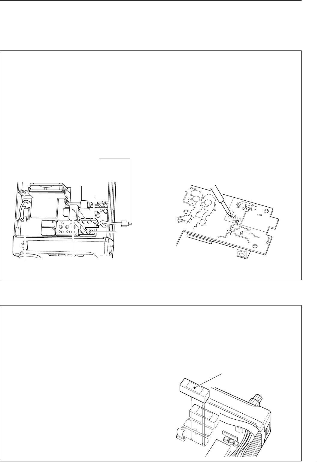
60
10
OPTIONAL INSTALLATIONS/SETTINGS
■CCRR--228822
HHIIGGHH
--
SSTTAABBIILLIITTYYCCRRYYSSTTAALLUUNNIITT
By installing the CR-282, the total frequency stability
of the transceiver will be improved.
➀Remove the bottom cover as shown on the oppo-
site page.
➁Remove the 5 screws and 2 flat cables holding the
PLL unit in place.
➂Remove the existing crystal unit.
➃Put the CR-282 in the space available as shown in
the diagram.
➄Adjust the reference frequency at L601 using a
frequency counter (60.00000 MHz).
➅Return the shield case and bottom cover to their
original positions.
CR-282 frequency stability: ±0.5 ppm
(–30°C to +60°C;
–22°F to +140°F)
■IIFF ffiilltteerrss
Several IF filters are available for the IC-706MKIIG.
Choose a filter most appropriate to your operating
needs.
NNoottee:: After filter installation, specify the installed filter
using initial set mode (items 9, 10). Otherwise, the
installed filter will not function properly.
FL-100
CW NARROW FILTER
500 Hz/–6 dB
FL-101
CW NARROW FILTER
250 Hz/–6 dB
FL-103
SSB WIDE FILTER
2.8 kHz/–6 dB
FL-223
SSB NARROW FILTER
1.9 kHz/–6 dB
FL-232
CW
/
RTTY NARROW FILTER
350 Hz/–6 dB
➀Remove the top cover as shown on the previous
page.
➁Install the desired filter as shown in the diagram
below.
•These filters can be installed in either direction.
➂Replace the top cover.
Filter
PLL unit
CR-282
Reference freq. check point
(60.00000 MHz)
ribbon
cable
ribbon
cable
existing
crystal
L601
PLL unit (bottom)
Spaces for 2 optional filters
available.
IC-706MKIIG.qxd 02.3.27 13:53 Page 60
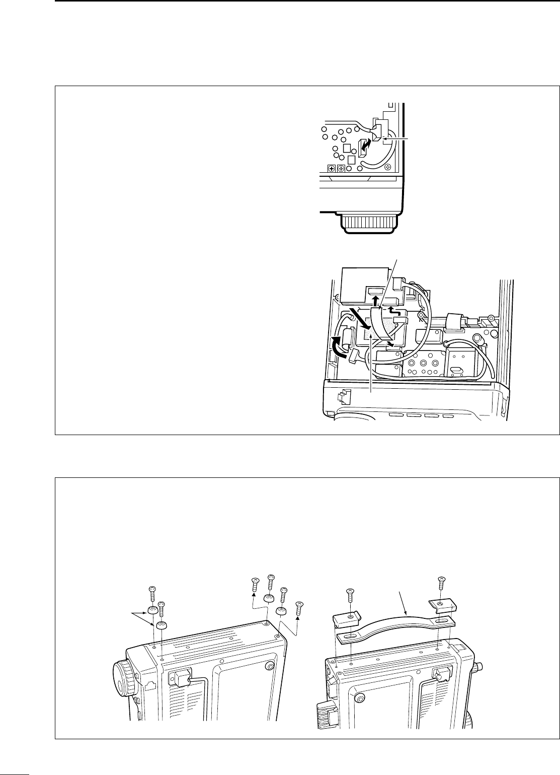
61
OPTIONAL INSTALLATIONS/SETTINGS
10
■UUTT--110066
DDSSPPRREECCEEIIVVEERRUUNNIITT
DIInnssttaallllaattiioonn
➀Open the transceiver case as shown on p. 59.
➁Remove the 4-pin connector (P251) from J1413
on the MAIN unit (top side) and plug it into J1 of the
UT-106 on the PLL unit (bottom side).
➂Plug the 4-pin connector (P1) from the UT-106
into J1413 on the MAIN unit.
➃Plug the supplied ribbon cable into J3 on the UT-
106 and J253 on the PLL unit.
•Be careful of the orientation of the ribbon cable.
➄Attach the UT-106 to the PLL unit, using the exist-
ing guide for alignment, as illustrated at right.
➅Reassemble the transceiver.
DOOppeerraattiioonn
Refer to the instructions supplied with the UT-106 for
operating details.
■MMBB--7722
CCAARRRRYYIINNGGHHAANNDDLLEE
The optional MB-72
CARRYING HANDLE
is convenient
when carrying the transceiver for DX’peditions, field
operation, etc.
➀Remove the 2 screws from the right side of the
transceiver as shown below.
➁Replace those with 2 supplied screws plus rubber
feet and additionally attach 2 more supplied screws
(including rubber feet) as shown below.
•When replacing the 2 screws at the rear, be sure to
squeeze the top and bottom covers together to ensure
proper alignment.
➂Attach the MB-72 to the left side of the transceiver
as shown below.
rubber
feet
carrying
handle
J1
P251
MAIN unit
UT-106
unit position
PLL unit
Remove the J1431 connector
from the PLL unit and replace
with the UT-106 connector
Be careful of the orientation
when connecting the
ribbon cable.
P1
J1431
P253
P1
J3
J1
IC-706MKIIG.qxd 02.3.27 13:53 Page 61
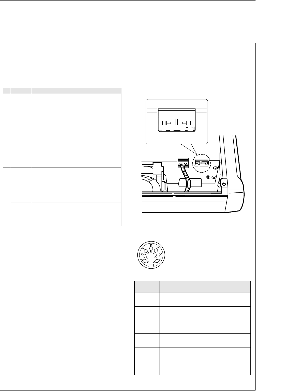
62
■AATT--118800 iinntteerrnnaall sswwiittcchh ddeessccrriippttiioonn
The optional AT-180 has 3 operating conditions for
HF band operation. Select a suitable condition
according to your antenna system.
➀Remove the top cover of the AT-180.
➁Set the tuner switches to the desired positions
according to the table below.
•SSppeecciiffiiccaattiioonnss ffoorr tthhee AATT--118800
•Frequency coverage : 1.9 –54 MHz
•Input impedance : 50 Ω
•Maximum input : 120 W
power
•Minimum tuning : 8 W
power
•Matching impedance : 16.7–150 Ω(HF band)
range 20 –125 Ω(50 MHz band)
•Tuning accuracy : Less than SWR 1.5:1
•Insertion loss : Less than 1.0 dB
(after tuning)
•Power supply : 13.8 V DC/1 A (supplied from
requirements the transceiver’s ACC socket)
•Dimensions (mm/in) : 167(W) ×58.6(H) ×225(D)
69⁄16(W) ×25⁄17(H) ×87⁄8(D)
•Weight : 2.4 kg; 5 lb 4 oz
•Supplied accessories : coaxial cable (1 m),
ACC cable (DIN 13 pins)
•AATT--118800 iinnssiiddee ttoopp ccoovveerr
•CCoonnnneeccttoorr iinnffoorrmmaattiioonn ffoorr AACCCC((22)) ssoocckkeett
S2 S1
DC BA
ACC 2
1
2
3
4
76
5
PPIINN NNOO..//
NNAAMMEEDDEESSCCRRIIPPTTIIOONN
➀8 V Regulated 8 V output.
(10 mA max.)
➁GND Connects to ground.
➂SEND
Input/output pin.
Goes to ground when transmitting (20 mA
max). When grounded, transmits.
➃BAND Band voltage output.
(Varies with amateur band; 0 to 8.0 V).
➄ALC ALC output voltage (–4 to 0 V).
➅NC No connection.
➆13.8V
13.8 V output when power is ON (1 A max).
SSWWPPoossiittiioonn
OOppeerraattiioonn
S1
A
(default)
The tuner operating condition is set by S2
described below.
B
THROUGH INHIBIT
The tuner tunes the antenna even when
the antenna has poor SWR (up to VSWR
3:1 after tuning). In this case, manual tun-
ing is necessary each time you change the
frequency although the tuner automatical-
ly starts tuning when the VSWR is higher
than 3:1. This setting is called “through
inhibit,” however, the tuner is set to
“through” if the VSWR is higher than 3:1
after tuning.
S2
C
TUNER SENSITIVE CONDITION
The tuner tunes each time you transmit
(except SSB mode). Therefore, the lowest
SWR is obtained at any given time.
For SSB mode, the same condition as the
“D” position.
D
(default)
NORMAL CONDITION
The tuner tunes when the SWR is higher
than 1.5:1. Therefore, the tuner activates
only when tuning is necessary.
10
OPTIONAL INSTALLATIONS/SETTINGS
IC-706MKIIG.qxd 02.3.27 13:53 Page 62
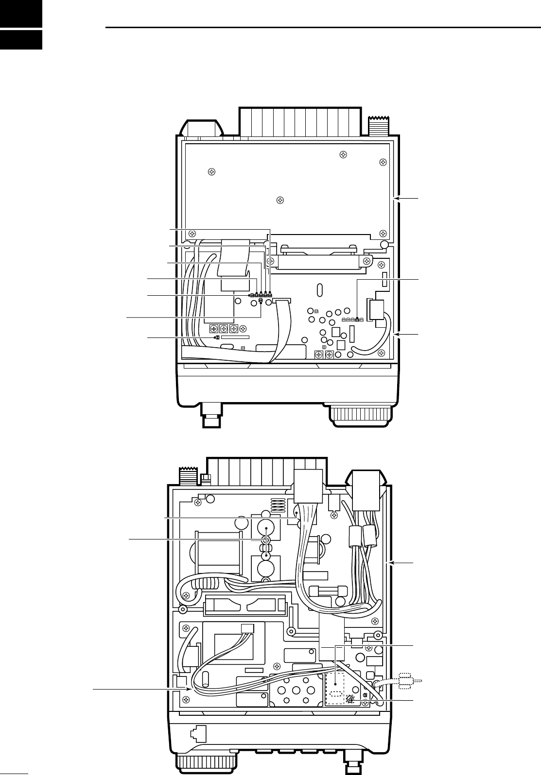
63
11 IINNTTEERRNNAALL VVIIEEWWSS
The internal speaker has
been removed in this
diagram for illustration
purposes.
FM deviation adj.
AM Tx carrier adj.
HF Tx power adj.
50 MHz Tx power adj.
NB sencitivity adj.
ID APC adj.
144 MHz Tx power adj.
430 MHz Tx power adj.
FILTER unit
MAIN unit
PLL unit
HF Final amplifier
(SRFJ7044 x 2)
PA unit
Reference freq. adj. (L601)
(when optional crystal
is installed)
Optional crystal (CR-282)
Reference freq. check point
(60.000 MHz)
144/430 MHz Final amplifier
(SRFJ7044)
DTToopp vviieeww
DBBoottttoomm vviieeww
CCaauuttiioonn::
The transceiver has been
thoroughly tested and
adjusted at the factory
before being shipped.
The transceiver warranty
does not cover any prob-
lems caused by unautho-
rized internal adjustment.
IC-706MKIIG.qxd 02.3.27 13:53 Page 63

64
12
OOPPTTIIOONNSS
IICC--PPWW11HF + 50 MHz 1 kW LINEAR AMPLIFIER
Full-duty 1 kW linear amplifier
including an automatic antenna
tuner. Has automatic tuning and
band selection capability. Full
break-in (QSK) operation is possi-
ble. The amplifier/power supply
unit and the remote control unit are
separated. The OPC-599 is nec-
essary to connect the IC-
706MKIIG to the IC-PW1.
AATT--118800HF/50 MHz AUTOMATIC
ANTENNA TUNER
Fully automatic antenna tuner with preset
memories for each 100 kHz. Unique “auto-
matic tuner on” function is available. See p. 62
for AT-180 specifications.
HHMM--111188TTHAND MICROPHONE
Includes DTMF keypad, hand microphone.
SSMM--2200DESKTOP MICROPHONE
Includes [UP]/[DOWN] switches and a low
cut function. The OPC-589 is necessary to
use this microphone.
MMBB--6655MOUNTING BASE
Allows you to conveniently vehicle-mount the
front panel of the IC-706MKIIG. An MB-63
must be used in combination with the MB-65.
AAHH--22bbANTENNA ELEMENT
A 2.5 m long antenna
element for mobile
operation with the AH-
3.
•Frequency coverage
3.5–28 MHz band
with the AH-3
SSMM--88DESKTOP MICROPHONE
Including 2 connection cables for simultane-
ous connection of 2 transceivers. Has
[UP]/[DOWN] switches. The OPC-589 is
necessary to use this microphone.
MMBB--6633MOUNTING BRACKET
Metal plate for attaching the front panel to a
wall or other such flat surface.
AAHH--44HF AUTOMATIC ANTENNA
TUNER
Specially designed to tune a long wire anten-
na for portable or mobile HF/50 MHz opera-
tion. The “PTT tune” function provides simple
operation.
•Input power rating: 150 W
PPSS--8855DC POWER SUPPLY
Light weight switching regulator system
power supply.
•Output voltage: 13.8 V DC
•Max. current drain: 20 A
MMBB--6622MOBILE MOUNTING BRACK-
ET
Mounts the transceiver main body, with or
without the front panel, inside a vehicle.
IC-706MKIIG.qxd 02.3.27 13:53 Page 64

65
12 OPTIONS
CCRR--228822HIGH-STABILITY CRYSTAL UNIT
Contains a temperature-compensating oven heater and crystal unit for
frequency stability.
•Frequency stability: ±0.5 ppm (–10°C to +60°C; +14°F to +140°F)
FFLL--110000CW NARROW FILTER (500 Hz/–6 dB)
FFLL--110011CW NARROW FILTER (250 Hz/–6 dB)
FFLL--110033SSB WIDE FILTER (2.8 kHz/–6 dB)
FFLL--222233SSB NARROW FILTER (1.9 kHz/–6 dB)
FFLL--223322CW/RTTY NARROW FILTER (350 Hz/–6 dB)
Two of the above 5 filters can be installed at one time.
HHMM--110033HAND MICROPHONE
Standard hand microphone.
OOPPCC--559999ADAPTER CABLE
13-pin, ACC connector to 7-pin + 8-pin ACC connector.
OOPPCC--774422ACC 13-PIN CABLE
Required when using both the AT-180 and a 2 m linear ampli-
fier.
MMBB--7722CARRYING HANDLE
Convenient when carrying the transceiver.
UUTT--110022VOICE SYNTHESIZER UNIT
UUTT--110066DSP RECEIVE UNIT
SSPP--2211EXTERNAL SPEAKER
External speaker designed for base station
operation.
•Input impedance: 8 Ω
•Max. input power: 5 W
OOPPCC--558811SEPARATION CABLE
OOPPCC--558877SEPARATION CABLE
Provide front panel detached operation for
mobile installations or compact transceiver
operation.
•OPC-581: 3.5 m (11.5 ft)
•OPC-587: 5 m (16.4 ft)
SSPP--1100EXTERNAL SPEAKER
SSPP--1122EXTERNAL SPEAKER
External speakers suitable for mobile opera-
tion.
SP-12: Slim-type; 8 Ω/3 W
SP-10: Compact-type; 4 Ω/5 W
CCTT--1177CI-V LEVEL CONVERTER
UNIT
For remote transceiver control using a per-
sonal computer equipped with an RS-232C
port. You can change frequencies, operating
mode, memory channels, etc., via your com-
puter.
SSPP--77EXTERNAL SPEAKER
Compact speaker for base station operation.
Height can be adjusted for your convenience.
•Input impedance: 8 Ω
•Max. input power: 5 W
CCTT--1166SATELLITE INTERFACE UNIT
Easy tuning when connecting another Icom
VHF transceiver for instant satellite commu-
nications.
OOPPCC--558899MICROPHONE ADAPTER
CABLE
Conversion between 8-pin modular and 8-pin
metal connector for using a desktop micro-
phone with the IC-706MKIIG.
SSPP--2200EXTERNAL SPEAKER
Equipped with 4 types of audio filters, a head-
phone jack and can be connected to 2 trans-
ceivers.
•Input impedance: 8 Ω
•Max. input power: 5 W
SP-12 SP-10
PPSS--112255DC POWER SUPPLY
Light weight switching regulator system
power supply.
•Output voltage: 13.8 V DC
•Max. current drain: 25 A
IC-706MKIIG.qxd 02.3.27 13:53 Page 65
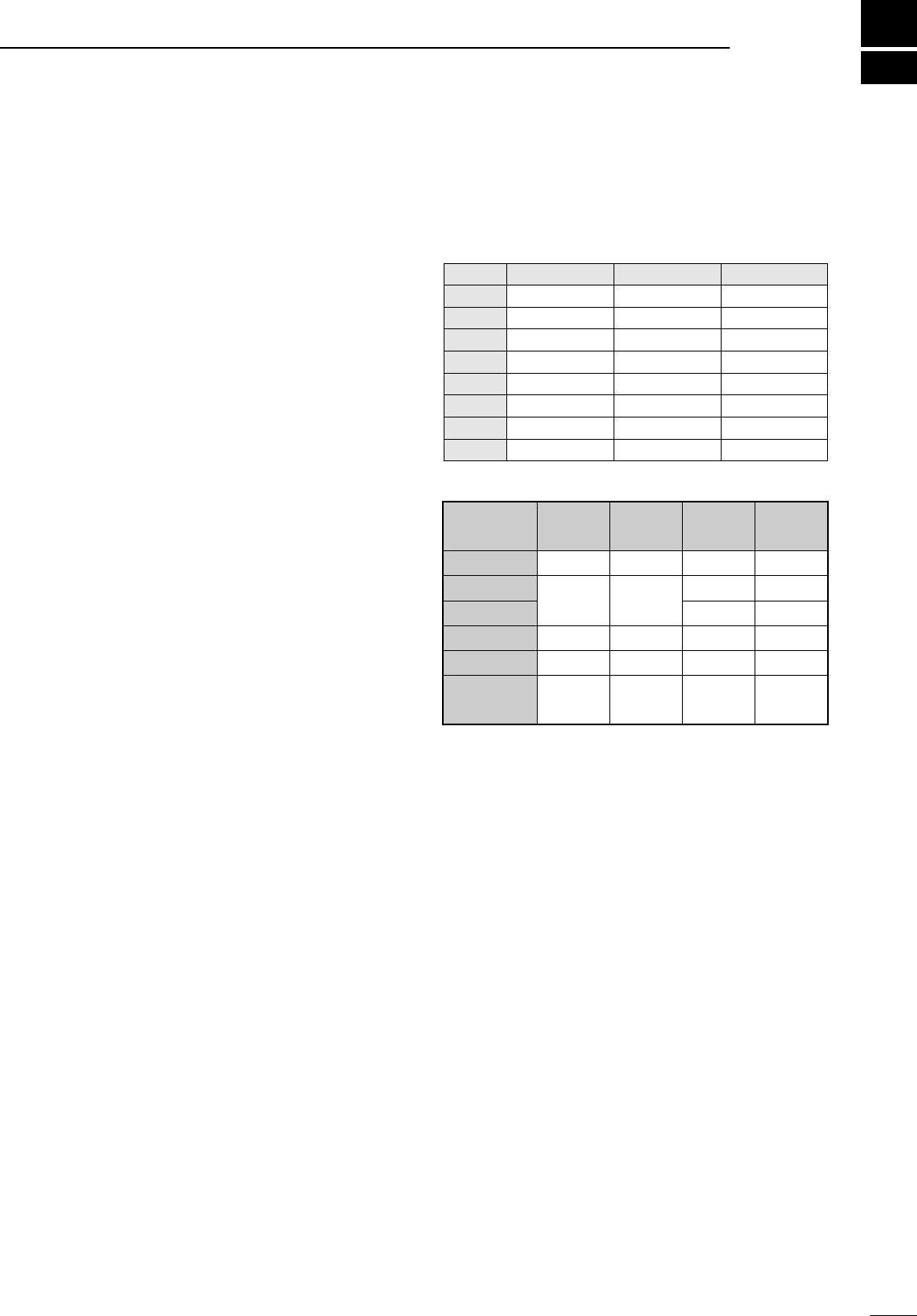
66
13
SSPPEECCIIFFIICCAATTIIOONNSS
■GGEENNEERRAALL
•Frequency coverage : Receive
30 kHz –199.999999 MHz*
400–470.000 MHz*
Transmit
1.800–1.99999 MHz*
3.500–3.9999 MHz*
7.000–7.300 MHz*
10.100–10.150 MHz
14.000–14.350 MHz
18.068–18.168 MHz
21.000–21.450 MHz
24.890–24.990 MHz
28.000–29.700 MHz
50.000–54.000 MHz*
144.000–148.000 MHz*
430.000–450.000 MHz*
*Depending on version.
•Mode : SSB, CW, AM, FM, WFM, RTTY
(WFM is for receive only)
•Number of memory : 107 (split memory: 99; scan edges: 6;
channels call channels: 2)
•Antenna connector : SO-239 ×2 (for HF/50 MHz and
144/430 MHz)/50 Ω
•Usable temperature : –10°C to +60°C (+14°F to +140°F)
range
•Frequency stability : Less than ±7 ppm from 1 min. to 60
min. after power ON. After that,
rate of stability change is less than
±1 ppm/hr. at +25°C (+77°F).
Temperature fluctuations (0°C to
+50°C; + 32°F to +122°F) less than
± 5 ppm.
•Power supply : 13.8 V DC ±15% (negative ground)
requirement
•Current drain : Transmit 20 A
(at 13.8 V DC) Receive squelched 1.8 A
max. audio 2.0 A
•Dimensions : 167(W) ×58(H) ×200(D) mm
69⁄16(W) ×25⁄16(H) ×77⁄8(D) in
(projections not included)
•Weight : 2.45 kg (5 lb 6 oz)
•CI-V connector : 2-conductor 3.5 (d) mm (1⁄8˝)/8 Ω
•ACC connector : 13-pin
■TTRRAANNSSMMIITTTTEERR
•Output power :
SSB, CW, FM, RTTY 5 –100 W (1.8–50 MHz bands)
5–50 W (144 MHz band)
2–20 W (430 band)
AM 2–40 W (1.8–50 MHz bands)
2–20 W (144 MHz band)
2–8 (430 band)
•Modulation system :
SSB Balanced modulation
AM Low level modulation
FM Variable reactance modulation
•Spurious emissions : Less than –60 dB*
*spurious freq.: below 30 MHz: –50 dB (typ.); above 50 MHz: –60 dB
(typ.).
•Carrier suppression : More than 40 dB
•Unwanted sideband : More than 50 dB
•Microphone : 8-pin modular jack (600 Ω)
connector
•KEY connector : 3-conductor 6.35 (d) mm (1⁄4")
•RTTY connector : 3-conductor 3.5 (d) mm (1⁄8")
■RREECCEEIIVVEERR
•Receive system :
SSB, CW, AM, RTTY Double-conversion superheterodyne
WFM
FM Triple-conversion superheterodyne
•Intermediate frequencies:
•Sensitivity (pre-amp ON):
•Squelch sensitivity (threshold; preamp ON) :
SSB Less than 5.6 µV
FM Less than 0.3 µV
•Selectivity* :
SSB, CW, RTTY More than 3.0 kHz/–6 dB
Less than 4.8 kHz/–60 dB
AM/FM-N More than 8.0 kHz/ –6 dB
Less than 30.0 kHz/–40 dB
FM More than 12.0 kHz/–6 dB
Less than 30.0 kHz/–60 dB
*Without optional filter and with mid
band selected.
•Spurious and image rejection ratio:
HF More than 70 dB
50 MHz More than 65 dB (except IF through)
144/430 MHz More than 65 dB
•Audio output power : More than 2.0 W at 10% distortion with
an 8 Ωload
•RIT variable range : ±9.99 kHz max.
•PHONES connector : 3-conductor 3.5 (d) mm (1⁄8˝)/8 Ω
•EXT SP connector : 2-conductor 3.5 (d) mm (1⁄8˝)/8 Ω
MMOODDEE11sstt22nndd33rrdd
SSSSBB69.0115 MHz 9.0115 MHz —
AAMM69.0100 MHz 9.0100 MHz —
AAMM--NN69.0115 MHz 9.0115 MHz —
RRTTTTYY69.0105 MHz 9.0105 MHz —
FFMM69.0115 MHz 9.0115 MHz 455 kHz
FFMM--NN69.0100 MHz 9.0100 MHz 455 kHz
WWFFMM70.7000 MHz 10.7000 MHz —
CCWW69.0106 MHz 9.0106 MHz —
FFrreeqquueennccyy
rraannggee
SSSSBB//CCWW
10 dB S/N
AAMM
10 dB S/N
FFMM
12 dB SINAD
WWFFMM
12 dB SINAD
0.5–1.8 MHz —13 µV — —
1.8–28 MHz 0.15 µV 2.0 µV — —
28–29.7 MHz 0.5 µV —
50 MHz band 0.12 µV 1.0 µV 0.25 µV —
76–108 MHz ———10.0 µV
144/430 MHz
bands 0.11 µV 1.0 µV 0.18 µV —
IC-706MKIIG.qxd 02.3.27 13:53 Page 66
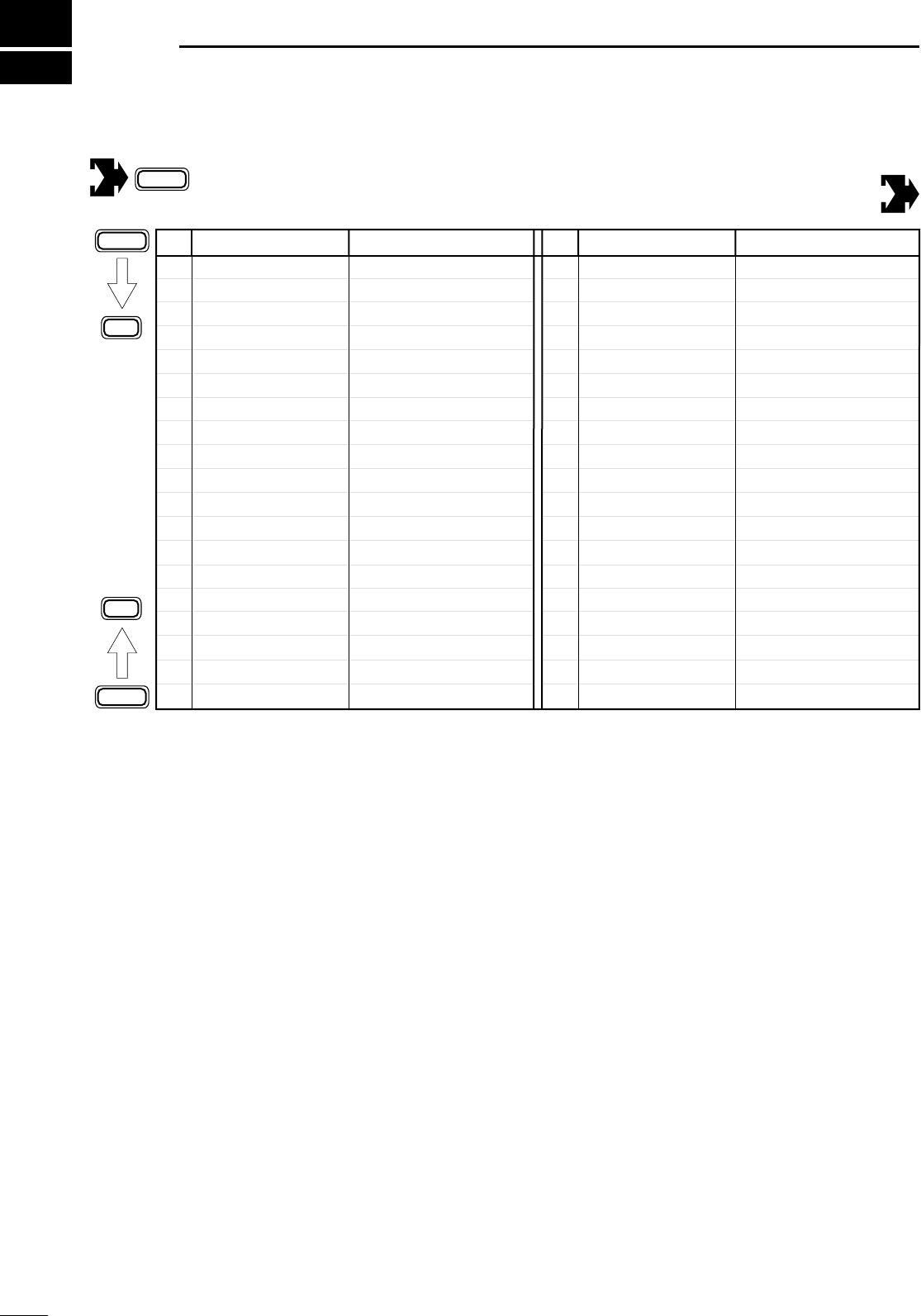
67
14 MMEENNUU GGUUIIDDEE
Initial set mode
No. Indication Description
1 MODE SELECT
2 BEEP
3 BAND BEEP
4 BACK LIGHT
5 KEY LIGHT
6 AUTO OFF
7 RF/SQL
8 SUB DIAL
9 OPT.FIL 1
10 OPT.FIL 2
11 PEAK HOLD
12 QUICK SPLIT
Mode availability
Confirmation beeps
Band edge beeps
Display backlighting
Key backlighting
Auto power OFF function
RF gain/squelch control
Sub dial RIT function
Speech synthesizer lang.
Speech synthesizer speed
Speech synthesizer S-meter
Meter peak function
[UP]/[DN] speed
Auto tune start function
No. Indication Description
13 SPLIT LOCK
PTT tune function
14 SPL OFFSET
15 DUP HF
16 DUP 50M
17 DUP 144M
18 DUP 430M
19 1TOUCH RPTR
No. of memory pads
20 AUTO RPTR
21 SCAN RESUME
22 SCAN SPEED
23 U/D SPEED
24 AM NB
25 PAD CH
26 PWR ON CHK
27 A-TUNE STRT
28
VSEND SEL
29
SPEECH LANG
30
SPEECH SPD
31
32
33 S-LVL SPC
34 CI-V ADDRES
35 CI-V BAUD
36 CI-V TRN
37 CI-V 731
Quick split function
Split lock function
Quick split offset
Quick split offset (HF)
Quick split offset (50 MHz)
Quick split offset (144 MHz)
Quick split offset (430 MHz)
One touch repeater
Scanning speed
Auto repeater function
Scan resume condition
Optional filter 1
Optional filter 2
Power ON check function
AM noise blanker
PTT TUNE
9600 MODE Packet data speed
ACC output selection
CI-V address assignment
Data transfer rate
CI-V transceive
CI-V 731
+ power ON Power OFF then ON to exit initial set mode.
MENU
MENU
Y
Z
LOCK
IC-706MKIIG.qxd 02.3.27 13:53 Page 67
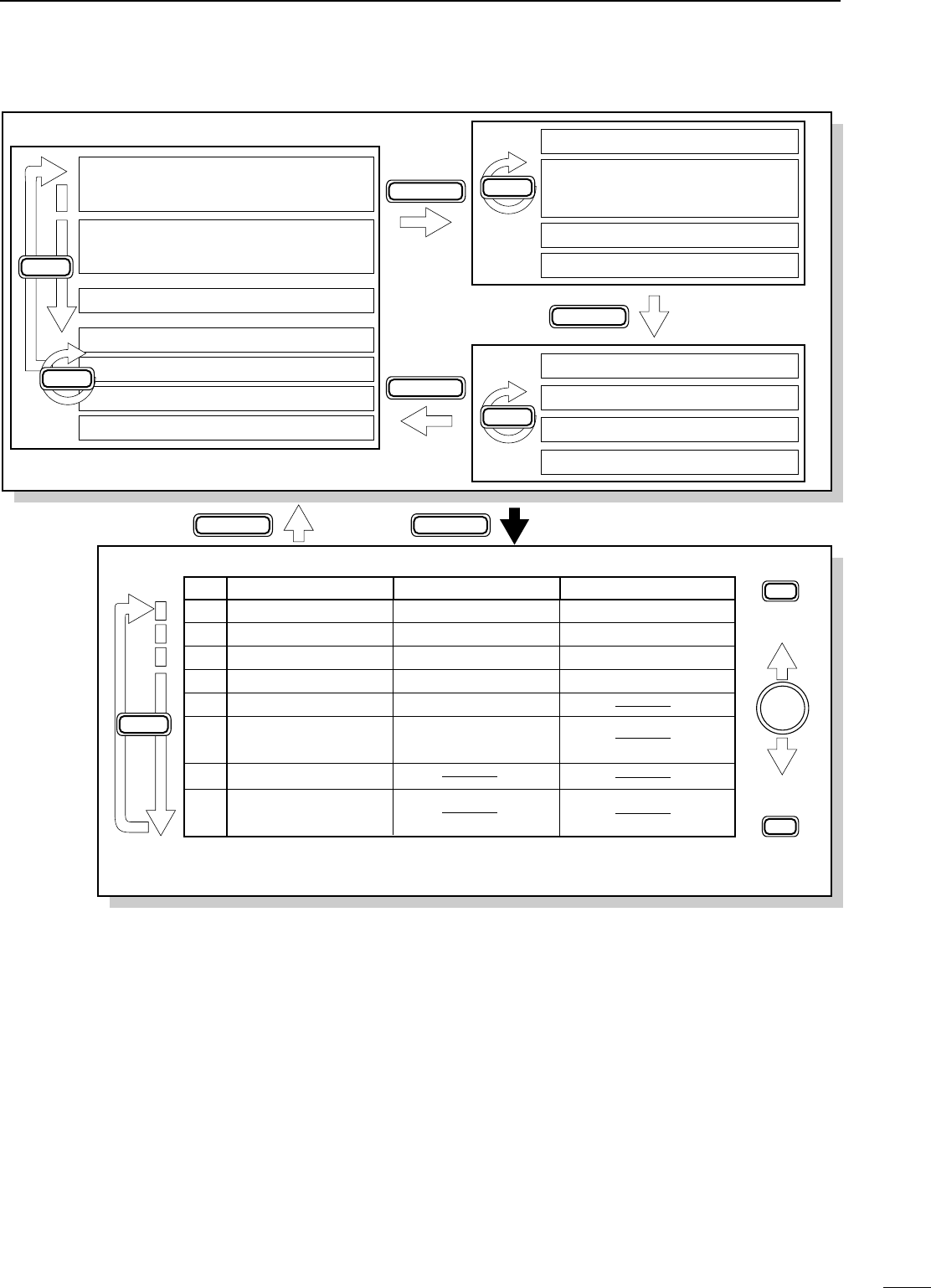
68
14
MENU GUIDE
M1 SPL A/B
XFC
A=B
M2 MW MÜV
MCL
V/M
M3 FIL NB MET
M4 VOX COM AGC
VOXM4 COM TON
1/4
1/4
M4 AGC
BRKM4 AGC
S1 MW MPW MPR
S2 SCN PRI
SEL
V/M
Quick set mode
For 2 sec.
MENU
MENU
(SSB/AM)
(when split
is ON) (in memory
mode)
(in memory mode)
(CW)
(RTTY)
(FM)
S3 7 50 144
S4 ANF NR NRL
G1 BAND scope
G2 IF SHIFT
G3 TX freq.
G4 Memory name
DISPLAY
DISPLAY
DISPLAYDISPLAY
MENU
MENU
Y
Y
M-CH
No.
Q1 RF POWER RF POWER RF POWER
Q2 MIC GAIN CW PITCH RTTY TONE
Q3 VOX DELAY
VOX GAIN
BK-IN DELAY RTTY SHIFT
Q6 RATIO
Q7
Q4
CARRIER Freq*1
CW PADDLE RTTY KEYING
SSB/AM/FM mode
RPTR TONE*2
TONE SQL*2
CW mode RTTY mode
Q8 RPTR-T*3
T-SQL*4
Q5 KEY SPEED
ANTI VOX
*1SSB mode only; *2FM mode only; *3FM mode only/tone encoder ON;
*4FM mode only/tone squelch ON.
MODE
DISPLAY
IC-706MKIIG.qxd 02.3.27 13:53 Page 68

A-5564H-1EX-r
Printed in Japan
©2001 by Icom Inc.
1-1-32 Kamiminami, Hirano-ku, Osaka 547-0003, Japan
Count on us!
IC-706MKIIG.qxd 02.3.27 13:53 Page 69

ABOUT CE
•Version and frequency coverage
Europe (#02, #12)
Tx 1.800000– 1.850000
3.500000– 3.800000
7.000000– 7.100000
10.100000– 10.150000
14.000000– 14.350000
18.068000– 18.168000
21.000000– 21.450000
24.890000– 24.990000
28.000000– 29.700000
50.000000– 52.000000
144.000000– 146.000000
430.000000– 440.000000
Rx 0.030000– 29.999999
50.000000– 52.000000
144.000000– 146.000000
430.000000– 440.000000
Spain (#04,#14)
Tx 1.830000– 1.850000
3.500000– 3.800000
7.000000– 7.100000
10.100000– 10.150000
14.000000– 14.350000
18.068000– 18.168000
21.000000– 21.450000
24.890000– 24.990000
28.000000– 29.700000
50.000000– 50.200000
144.000000– 146.000000
430.000000– 440.000000
Rx 1.830000– 1.850000
3.500000– 3.800000
7.000000– 7.100000
10.100000– 10.150000
14.000000– 14.350000
18.068000– 18.168000
21.000000– 21.450000
24.890000– 24.990000
28.000000– 29.700000
50.000000– 50.200000
144.000000– 146.000000
430.000000– 440.000000
France (#03,#13)
Tx 1.810000– 1.850000
3.500000– 3.800000
7.000000– 7.100000
10.100000– 10.150000
14.000000– 14.350000
18.068000– 18.168000
21.000000– 21.450000
24.890000– 24.990000
28.000000– 29.700000
50.200000– 51.200000
144.000000– 146.000000
430.000000– 440.000000
Rx 1.810000– 1.850000
3.500000– 3.800000
7.000000– 7.100000
10.100000– 10.150000
14.000000– 14.350000
18.068000– 18.168000
21.000000– 21.450000
24.890000– 24.990000
28.000000– 29.700000
50.200000– 51.200000
144.000000– 146.000000
430.000000– 440.000000
Italy (#10,#20)
Tx 1.830000– 1.850000
3.500000– 3.800000
7.000000– 7.100000
10.100000– 10.150000
14.000000– 14.350000
18.068000– 18.168000
21.000000– 21.450000
24.890000– 24.990000
28.000000– 29.700000
50.000000– 51.000000
144.000000– 146.000000
430.000000– 434.000000
435.000000– 438.000000
Rx 1.830000– 1.850000
3.500000– 3.800000
7.000000– 7.100000
10.100000– 10.150000
14.000000– 14.350000
18.068000– 18.168000
21.000000– 21.450000
24.890000– 24.990000
28.000000– 29.700000
50.000000– 51.000000
144.000000– 146.000000
430.000000– 434.000000
435.000000– 438.000000
(UNIT: MHz)
DECLARATION
OF CONFORMITY
We Icom Inc. Japan
1-1-32 Kamiminami, Hirano-ku,
Osaka 547-0003 Japan
Kind of equipment: HF/
VHF/UHF ALL MODE TRANSCEIVER
This compliance is based on conformity according to Annex III of the
RTTE Directive 1999/5/EC using the following harmonised standards:
i) Article 3.1a
EN 60950 + A11
ii) Article 3.1b EN 301489-1 and EN 301489-15
iii) Article 3.2 EN 301 783-2
iv)
v)
Type-designation: i706MKIIG
Signature
Authorized representative name
Place and date of issue
T. Aoki
General Manager
Icom (Europe) GmbH
Himmelgeister straße 100
D-40225 Düsseldorf
Düsseldorf 13th Mar. 2001
Icom (Europe) GmbH
Declare on our sole responsibility that this equipment complies with the
essential requirements of the Radio and Telecommunications Terminal
Equipment Directive, 1999/5/CE, and that any applicable Essential Test
Suite measurements have been performed.
Version (where applicable):
•About DC power supply.
The use of IC-706MKIIG (#02, #12, #03, #13, #04, #14,
#10, #20) in combination with The DC power supply com-
plies with European Harmonised Standard regulations
under the conditions listed below.
Conditions
•In combination with PS-125
•When connected to a power supply via OPC-639
•
About IC-PW1
LINEAR AMPLIFIER
and SP-10,
SP-12, SP-20, SP-21
EXTERNAL SPEAKERS
.
The IC-PW1
LINEAR AMPLIFIER
and The SP-10, SP-12, SP-
20, SP-21
EXTERNAL SPEAKERS
do not comply with Euro-
pean Harmonised Standard regulations. Please do not use
these equipments within European countries.
INSTALLATION NOTES
For amateur base station installations it is recom-
mended that the forwards clearance in front of the an-
tenna array is calculated relative to the EIRP (Effective
Isotropic Radiated Power). The clearance height below
the antenna array can be determined in most cases
from the RF power at the antenna input terminals.
As different exposure limits have been recommended
for different frequencies, a relative table shows a
guideline for installation considerations.
Below 30 MHz, the recommended limits are specified
in terms of V/m or A/m fields as they are likely to fall
within the near-field region. Similarly, the antennae
may be physically short in terms of electrical length
and that the installation will require some antenna
matching device which can create local, high intensity
magnetic fields. Analysis of such MF installations is
best considered in association with published guidance
notes such as the FCC OET Bulletin 65 Edition 97-01
and its annexes relative to amateur transmitter instal-
lations. The EC recommended limits are almost identi-
cal to the FCC specified ‘uncontrolled’limits and tables
exist that show pre-calculated safe distances for differ-
ent antenna types for different frequency bands. Fur-
ther information can be found at http://www.arrl.org/.
•Typical amateur radio installation
Exposure distance assumes that the predominant ra-
diation pattern is forwards and that radiation vertically
downwards is at unity gain (sidelobe suppression is
equal to main lobe gain). This is true of almost every
gain antenna today. Exposed persons are assumed to
be beneath the antenna array and have a typical
height to 1.8 m.
The figures assume the worst case emission of con-
stant carrier.
For the bands 10 MHz and higher the following power
density limits have been recommended:
10 – 400 MHz 2 W/sq m
435 MHz 2.2 W/sq m
EIRP Clearance heights by frequency band
Watts 10–2 m 70 cm 23 cm 13cm and above
1 2.1 m 2 m 2 m 2 m
10 2.8 m 2.7 m 2.5 m 2.3 m
25 3.4 m 3.3 m 2.7 m 2.5 m
100 5 m 4.7 m 3.6 m 3.2 m
1000 12 m 11.5 m 7.3 m 6.3 m
Forward clearance, EIRP by frequency band
Watts 10–2 m 70 cm 23 cm 13cm and above
100 2 m 2 m 1.1 m 0.7 m
1000 6.5 m 6 m 3.5 m 3 m
10,000 20 m 18 m 11 m 7 m
100,000 65 m 60 m 35 m 29 m
In all cases any possible risk depends on the transmit-
ter being activated for long periods. (actual recom-
mendation limits are specified as an average during 6
minutes) Normally the transmitter is not active for long
periods of time. Some radio licenses will require that a
timer circuit automatically cuts the transmitter after 1–2
minutes etc.
Similarly some types of transmitter, SSB, CW, AM etc.
have a lower ‘average’output power and the assessed
risk is even lower.
Versions of the IC-706MKIIG which display the
“CE” symbol on the serial number seal, comply
with the essential requirements of the European
Radio and Telecommunication Terminal Direc-
tive 1999/5/EC.
This warning symbol indicates that this equip-
ment operates in non-harmonised frequency
bands and/or may be subject to licensing con-
ditions in the country of use. Be sure to check
that you have the correct version of this radio or
the correct programming of this radio, to com-
ply with national licensing requirement.
GER
AUT
GBR
IRL
FRA
NED
BEL
LUX
ESP
POR
ITA
GRE
SWE
DEN
FIN
< Intended Country of Use >
GER
AUT
GBR
IRL
FRA
NED
BEL
LUX
ESP
POR
ITA
GRE
SWE
DEN
FIN
< Intended Country of Use >
IC-706MKIIG
#02, #12
(Europe)
IC-706MKIIG
#04 ,#14
(Spain)
GER
AUT
GBR
IRL
FRA
NED
BEL
LUX
ESP
POR
ITA
GRE
SWE
DEN
FIN
< Intended Country of Use >
GER
AUT
GBR
IRL
FRA
NED
BEL
LUX
ESP
POR
ITA
GRE
SWE
DEN
FIN
< Intended Country of Use >
IC-706MKIIG
#03, #13
(France)
IC-706MKIIG
#10, #20
(Italy)
1-1-32 Kamiminami, Hirano-ku, Osaka 547-0003 Japan
Count on us!
A-6045H-1EU Printed in Japan
© 2001 Icom Inc.
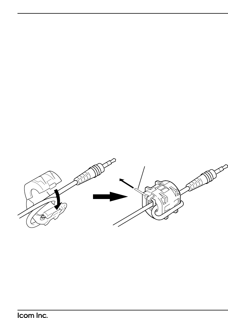
If the SP-7 external speaker is used with the IC-706MKIIG, please install the fer-
rite supplied bead on the speaker cable, as shown below.
• A ferrite bead and a cable fastener are supplied with IC-706MKIIG.
INSTALLATION NOTE:
• Install the ferrite bead as near as possible the connecting plug.
• Attach the ferrite bead making a loop with the cable as shown in the diagram at
below left.
• Fasten the ferrite bead and speaker cable with the supplied cable fastener.
ABOUT SP-7 EXTERNAL SPEAKER
Cable fastener
pull
1-1-32 Kamiminami, Hirano-ku, Osaka 547-0003 Japan
Count on us!
A-6045H-2EU Printed in Japan
© 2001 Icom Inc.