ICOM orporated 217800 HF/50 MHz All Mode Transceiver User Manual
ICOM Incorporated HF/50 MHz All Mode Transceiver Users Manual
UserManual.wiki
>
ICOM orporated
>
217800 User Manual
Users Manual
Navigation menu
Upload a User Manual
Namespaces
Wiki Guide
HTML
PDF
Info
Views
User Manual
Discussion / Help
Navigation
![iiRWARNING RF EXPOSURE! This deviceemits Radio Frequency (RF) energy. Extreme cautionshould be observed when operating this device. If youhave any questions regarding RF exposure and safetystandards please refer to the Federal CommunicationsCommission Office of Engineering and Technology’sreport on Evaluating Compliance with FCC Guidelinesfor Human Radio Frequency Electromagnetic Fields(OET Bulletin 65).RWARNING HIGH VOLTAGE! NEVER at-tach an antenna or internal antenna connector duringtransmission. This may result in an electrical shock orburn.RWARNING! NEVER operate the transceiverwith a headset or other audio accessories at high vol-ume levels. Hearing experts advise against continuoushigh volume operation. If you experience a ringing inyour ears, reduce the volume or discontinue use.RCAUTION! NEVER change the internal settingsof the transceiver. This result in reduced transceiverperformance and/or damage to the transceiver.In particular, incorrect settings for transmitter circuits,such as output power, idling current, etc., might dam-age the expensive final devices.The transceiver warranty does not cover any problemscaused by unauthorized internal adjustment.RNEVER apply AC to the [DC13.8V] jack on thetransceiver rear panel. This could cause a fire or ruinthe transceiver.RNEVER apply more than 16 V DC, such as a 24 Vbattery, to the [DC13.8V] jack on the transceiver rearpanel. This could cause a fire or ruin the transceiver.RNEVER let metal, wire or other objects touch anyinternal part or connectors on the rear panel of thetransceiver. This may result in an electric shock.RNEVER expose the transceiver to rain, snow orany liquids.RNEVER installing the transceiver in a place with-out adequate ventilation. Heat dissipation may be af-fected, and the transceiver may be damaged.RNEVER operate or touch the transceiver with wethands. This may result in an electric shock or damagethe transceiver.AVOID using or placing the transceiver in areas withtemperatures below –10°C (+14°F) or above +50°C(+122°F). Be aware that temperatures on a vehicle’sdashboard can exceed 80°C (+176°F), resulting in per-manent damage to the transceiver if left there for ex-tended periods.AVOID placing the transceiver in excessively dusty en-vironments or in direct sunlight.AVOID placing the transceiver against walls or puttinganything on top of the transceiver. This will obstructheat dissipation.Place unit in a secure place to avoid inadvertent useby children.During mobile operation, DO NOT operate the trans-ceiver without running the vehicle’s engine. Whentransceiver power is ON and your vehicle’s engine isOFF, the vehicle’s battery will soon become ex-hausted.Make sure the transceiver power is OFF before start-ing the vehicle. This will avoid possible damage to thetransceiver by ignition voltage spikes.During maritime mobile operation, keep the transceiverand microphone as far away as possible from the mag-netic navigation compass to prevent erroneous indica-tions.BE CAREFUL! The heatsink will become hot when op-erating the transceiver continuously for long periods.BE CAREFUL! If a linear amplifier is connected, setthe transceiver’s RF output power to less than the lin-ear amplifier’s maximum input level, otherwise, the lin-ear amplifier will be damaged.The LCD display may have cosmetic imperfectionsthat appear as small or dark spots. This is not a mal-function or defect, but a normal characteristic of LCDdisplays.Use Icom microphones only (supplied or optional).Other manufacturer’s microphones have different pinassignments, and connection to the IC-756PROIII maydamage the transceiver.For U.S.A. onlyCAUTION: Changes or modifications to this device,not expressly approved by Icom Inc., could void yourauthority to operate this device under FCC regulations.PRECAUTIONS](https://usermanual.wiki/ICOM-orporated/217800/User-Guide-467148-Page-3.png)
![11PANEL DESCRIPTION■Front panelqPOWER SWITCH [POWER/TIMER]➥While transceiver’s power is OFF:Push to turn power ON.•Turn the optional DC power supply ON in advance.•A/D converter calibration of the DSP unit starts and ittakes approx. 10 sec.➥While transceiver’s power is ON:❍Push momentarily to toggle the timer functionON and OFF. (p. 91)•The [TIMER] indicator in this switch lights while thetimer function is ON.❍Push for 1 sec. to turn power OFF.wTRANSMIT SWITCH [TRANSMIT]Selects transmitting or receiving.•The [TX] indicator lights red while transmitting and the[RX] indicator lights green when the squelch is open.eHEADPHONE JACK [PHONES]Accepts headphones.•Output power: 5 mW with an 8 Ωload.•When headphones are connected, the internal speakeror connected external speaker does not function.rELECTRONIC KEYER JACK [ELEC-KEY]Accepts a paddle to activate the internal electronickeyer for CW operation. (p. 38)•Selection between the internal electronic keyer, bug-keyand straight key operation can be made in keyer setmode. (p. 43)•A straight key jack is separately available on the rearpanel. See [KEY] on p. 11.•Keyer polarity (dot and dash) can be reversed in keyerset mode. (p. 43)•4-channel memory keyer is available for your conve-nience. (p. 40)tMICROPHONE CONNECTOR [MIC]Accepts the supplied or optional microphone.•See p. 114 for appropriate microphones.•See p. 18 for microphone connector information.yAF CONTROL [AF] (inner control)Varies the audio output level from the speaker.uMIC GAIN CONTROL [MIC GAIN]Adjusts microphone input gain.•The transmit audio tone in SSB mode can be adjusted inset mode. (p. 93)✔How to set the microphone gain.Set the [MIC] control so that the ALC meter sometimesswings during normal voice transmission in SSB mode.MIC GAINRecommended level for an Icom microphoneIncreasesDecreasesAF RF/SQLNo audio output Max. audio outputDecreases Increases(dot)(com)(dash)TIMERPOWERTRANSMITPHONESELEC-KEYMICTUNER MONITOR NB NRAF BAL NRRF/SQLMIC GAIN RF POWER COMP BK-IN DELAY KEY SPEEDF-1 F-2 F-3 F-4 F-5HF/50MHz TRANSCEIVERSSBCW/RTTYAM/FM FILTER EXIT/SETqwert!0!1!2yiou](https://usermanual.wiki/ICOM-orporated/217800/User-Guide-467148-Page-6.png)
![21PANEL DESCRIPTION1iRF GAIN CONTROL/SQUELCH CONTROL[RF/SQL] (outer control)Adjusts the RF gain and squelch threshold level.The squelch removes noise output from thespeaker (closed condition) when no signal is re-ceived.•The squelch is particularly effective for FM. It is alsoavailable for other modes.•12 to 1 o’clock position is recommended for any settingof the [RF/SQL] control.•The control can be set as ‘Auto’ (RF gain control in SSB,CW and RTTY; squelch control in AM and FM) orsquelch control (RF gain is fixed at maximum) in setmode as follows. (p. 98)•When setting as RF gain/squelch control•When functioning as RF gain control(Squelch is fixed open; SSB, CW, RTTY only)•When functioning as squelch control(RF gain is fixed at maximum.)While rotating the RF gain control, noise may beheard. This comes from the DSP unit and does notindicate an equipment malfunction.oRF POWER CONTROL [RF POWER]Continuously varies the RF output power from min-imum (5 W*) to maximum (100 W*).*AM mode: 5 W to 40 W!0 S/RF METER (p. 31)Shows the signal strength while receiving. Showsthe relative output power, SWR, ALC or compres-sion levels while transmitting.!1 MONITOR SWITCH [MONITOR] (p. 69)Monitors your transmitted IF signal.•The CW sidetone functions regardless of the [MONI-TOR] switch setting in CW mode.•The [MONITOR] indicator in this switch lights greenwhen the function is activated.!2 ANTENNA TUNER SWITCH [TUNER] (p. 88)➥Turns the internal antenna tuner ON and OFF(bypass) when pushed momentarily.➥Tunes the antenna manually when pushed for 1sec.•The [TUNER] indicator in this switch lights red whenthe function is activated or blinks during manual tun-ing.•When the tuner cannot tune the antenna, the tuningcircuit is bypassed automatically after 20 sec.RF POWERIncreasesDecreasesSquelch is open.S-meter squelchS-meter squelchthresholdNoise squelch threshold (FM mode)Shallow DeepNoise squelch (FM mode)Minimum RF gainAdjustablerangeMaximum RF gainRecommended levelRF gain adjustablerangeMaximum RF gainS-meter squelchNoise squelch (FM mode)Squelch is open.MODESSB, CWRTTYAM, FMAUTORF GAINSQLSQLSET MODE SETTINGSQLSQLRF GAIN + SQLRF GAIN + SQLRF GAIN + SQL](https://usermanual.wiki/ICOM-orporated/217800/User-Guide-467148-Page-7.png)
Adjusts the speech compression level in SSB.!4 SEMI BREAK-IN DELAY CONTROL[BK-IN DELAY]Adjusts the transmit-to-receive switching delay timefor CW semi break-in operation.!5 ELECTRONIC CW KEYER SPEED CONTROL[KEY SPEED] (p. 35)Adjusts the internal electronic CW keyer’s speed.•6 wpm (min.) to 60 wpm (max.) can be set.!6 MULTI-FUNCTION SWITCHESPush to select the functions indicated in the LCDdisplay to the right of these switches.•Functions vary depending on the operating condition.➥Selects the antenna connector betweenANT1 and ANT2 when pushed. (p. 87)➥Turns the [RX ANT] (receive antenna) ONand OFF when pushed for 1 sec.•When the receive antenna is activated, theantenna which is connected to the [ANT1] or[ANT2] is used for transmission only.When a transverter is in use, this [ANT]does not function and ‘XVERT’ appears.➥Selects RF power (Po), SWR, ALC orCOMP metering during transmit. (p. 31)➥Switches the multi-function digital meterON and OFF when pushed for 1 sec.➥Selects one of 2 receive RF preamps orbypasses them. (p. 57)•“P. AMP1” activates 10 dB preamp.•“P. AMP2” activates 16 dB high-gain preamp.✔What is the preamp?The preamp amplifies received signals in the front end cir-cuit to improve the S/N ratio and sensitivity. Select “P. AMP1”or “P. AMP2” when receiving weak signals.➥Selects 6 dB, 12 dB or 18 dB attenuator,or bypasses them.✔What is the attenuator?The attenuator prevents a desired signal from distortingwhen very strong signals are near the desired frequency, orwhen very strong electric fields, such as from a broadcast-ing station, are near your location.ATTATTOFFOFFP.AMPP.AMPOFFOFFMETERMETERPoPoANTANT1Slow FastKEY SPEEDBK-IN DELAYShort delay for high speed keying(2 dot)Long delay for slow speed keying(13 dot)COMPCompression level decreases Compression level increasesTIMERPOWERTRANSMITPHONESELEC-KEYMICTUNER MONITOR NB NRAF BAL NRRF/SQLMIC GAIN RF POWER COMP BK-IN DELAY KEY SPEEDF-1 F-2 F-3 F-4 F-5HF/50MHz TRANSCEIVERSSBCW/RTTYAM/FM FILTER EXIT/SET!5!4!3!6!7!8@0 !9](https://usermanual.wiki/ICOM-orporated/217800/User-Guide-467148-Page-8.png)
![41PANEL DESCRIPTION1➥Activates or selects fast, middle or slowAGC time constant when pushed. (p. 59)•“FAST” is only available for FM mode.➥Enters the AGC set mode when pushedfor 1 sec. (p. 59)AGC time constant can be set between 0.1 to8.0 sec. (depends on mode), or turned OFF. While“OFF” is selected, the S-meter does not function.✔What is the AGC?The AGC controls receiver gain to produce a constant audiooutput level, even when the received signal strength is variedby fading, etc. Select “FAST” for tuning and select “MID” or“SLOW” depending on the receiving condition.➥Turns the VOX function ON and OFFwhen pushed in a phone mode (SSB, AMor FM mode). (p. 65)➥Enters the VOX set mode when pushedfor 1 sec. in a phone mode. (p. 65)✔What is the VOX function?The VOX function (voice operated transmission) starts trans-mission without pushing the transmit switch or PTT switchwhen you speak into the microphone; then, automatically re-turns to receive when you stop speaking.➥Selects semi break-in, full break-in oper-ation, or turns the break-in operationOFF when pushed in CW mode. (p. 66)✔What is the break-in function?The break-in function switches transmit and receive with CWkeying. Full break-in (QSK) can monitor the receive signalduring keying.➥Turns the RTTY filter ON and OFF inRTTY mode. (p. 45)•When the RTTY filter is turned ON, [TWINPBT] functions as the IF shift control.➥Enters the RTTY filter set mode whenpushed for 1 sec. in RTTY mode. (p. 45)✔What is the IF shift?The IF shift function electronically changes the center of theIF (Intermediate Frequency) passband frequency to reject in-terference. Only the inner control of [TWIN PBT] can be usedfor the IF shift control.➥Turns the speech compressor ON andOFF in SSB mode. (p. 67)➥Switches the narrow, middle or widetransmit filter when pushed for 1 sec.✔What is the speech compressor?The speech compressor compresses the transmitter audioinput to increase the average audio output level. Therefore,talk power is increased. This function is effective for long dis-tance communication or when propagation conditions arepoor.➥Turns the 1⁄4function ON and OFF inSSB data, CW and RTTY modes. (p. 27)•1⁄4function sets dial rotation to 1⁄4of normalfor fine tuning.➥Switches the tone encoder, tone squelchfunction and no tone operation whenpushed in FM mode. (pgs. 52, 53➥Enters the tone set mode when pushedfor 1 sec. in FM mode. (pgs. 52, 53)!7 NOISE REDUCTION LEVEL CONTROL [NR] (outer control; p. 64)Adjusts the noise reduction level when the noise re-duction is in use. Set for maximum readability.•To activate this control, turn the noise reduction ON inadvance (!8).!8 NOISE REDUCTION SWITCH [NR] (p. 64)Push to switch the noise reduction ON and OFF.•The [NR] indicator in this switch lights green when thefunction is activated.!9 NOISE BLANKER SWITCH [NB] (p. 62)➥Switches the noise blanker ON and OFF whenpushed. The noise blanker reduces pulse-typenoise such as that generated by automobile igni-tion systems. This function cannot be used forFM, or non-pulse-type noise.•The [NB] indicator in this switch lights green when thefunction is activated.➥Enters the noise blanker level set mode whenpushed for 1 sec.@0 BALANCE CONTROL [BAL] (inner control; p. 63)Adjusts the audio output balance between main andsub readout frequencies while in dualwatch.BAL NRIncreases mainreadout gain Increases subreadout gainNoise blanker OFF Noise blanker ONNB NBNoise reduction OFF Noise reduction ONNR NRBAL NRDecreasesOFFIncreasesTONETONEOFFOFF1/41/4OFFOFFCOMPCOMPOFFOFFWIDEWIDERTTYRTTYFILFILOFFOFFBK-INBK-INOFFOFFVOXVOXOFFOFFAGCAGCMIDMID](https://usermanual.wiki/ICOM-orporated/217800/User-Guide-467148-Page-9.png)
![51PANEL DESCRIPTION■Front panel (continued)@1 LCD FUNCTION SWITCHES [F-1]–[F-5]Push to select the function indicated in the LCD dis-play above these switches.•Functions vary depending on the operating condition.@2 MODE SWITCHESSelects the desired mode. (p. 29)•Announces the selected mode when an optional UT-102is installed. (pgs. 101, 104)➥Selects USB and LSB mode alternately.➥Selects SSB data mode (USB-D, LSB-D)when pushed for 1 sec. in SSB mode.➥Selects CW and RTTY mode alternately.➥Switches CW and CW-R (CW reverse)mode when pushed for 1 sec. in CWmode.➥Switches RTTY and RTTY-R (RTTY re-verse) mode when pushed for 1 sec. inRTTY mode.➥Selects AM and FM mode alternately.➥Selects AM/FM data mode (AM-D, FM-D)when pushed for 1 sec. in AM or FMmode.@3 FILTER SWITCH [FILTER] (p. 61)➥Push to select one of 3 IF filter settings.➥Push for 1 sec. to enter the filter set mode.@4 EXIT/SET SWITCH [EXIT/SET]➥Push to exit from a set mode, etc.➥Push for 1 sec. to enter the set mode screen.(p. 92)@5 REC/PLAY SWITCH [REC/PLAY] (p. 72)➥Push momentarily to playback the recorded con-tents in the channel R4 of the voice memory.➥Push for 1 sec. to record the receiving signal con-tents into the channel R4 (max. 15 sec.) of thevoice memory.@6 TUNING DIAL (p. 25)Changes the displayed frequency, selects set modesettings, etc.@7 LOCK/SPEECH SWITCH [LOCK/SPEECH]➥Push momentarily to toggle the dial lock functionON and OFF. (p. 64)➥Push for 1 sec. to announce the S-meter indica-tion and the selected readout frequency when anoptional UT-102 is installed. (p. 104)@8 RIT/∂∂TX CONTROL [RIT/∂∂TX] (pgs. 58, 68)Shifts the receive and/or transmit frequency withoutchanging the transmit and/or receive frequencywhile the RIT and/or ∂TX functions are ON.•Rotate the control clockwise to increase the frequency,or rotate the control counterclockwise to decrease thefrequency.•The shift frequency range is ±9.999 kHz in 1 Hz steps(or ±9.99 kHz in 10 Hz steps).RIT/∂TXLow shift High shiftAM/FMCW/RTTYSSBNB NRBAL NRCOMP BK-IN DELAY KEY SPEEDLOCKTXRXTWIN PBTCW PITCHF-1 F-2 F-3 F-4 F-5REC/PLAYLOCK/SPEECHRIT/ TXTXRIT CLEARSPLITMP-W MP-RDUALWATCHVFO/MEMOMAIN/SUBM.SCOPECHANGE1.8 3.5 710 14 1821 24 28GENE•501234567890F-INPENTYZMWM-CLTSXFCEIVERi7500PBT CLR NOTCHNOTCHSSBCW/RTTYAM/FM FILTER EXIT/SET@2 @4@3 @5 @6#6#1#2#3#0#4#5@9@8@7@1](https://usermanual.wiki/ICOM-orporated/217800/User-Guide-467148-Page-10.png)
![61PANEL DESCRIPTION1@9 RIT SWITCH [RIT] (p. 58)➥Turns the RIT function ON and OFF whenpushed.•Use the [RIT/∂TX] control to vary the RIT frequency.➥Adds the RIT shift frequency to the operating fre-quency when pushed for 1 sec.✔What is the RIT function?The RIT (Receiver Incremental Tuning) shifts the receive fre-quency without shifting the transmit frequency.This is useful for fine tuning stations calling you on an off-fre-quency or when you prefer to listen to slightly different-sounding voice characteristics, etc.#0 ∂∂TX SWITCH [∂∂TX] (p. 68)➥Turns the ∂TX function ON and OFF whenpushed.•Use the [RIT/∂TX] control to vary the ∂TX frequency.➥Adds the ∂TX shift frequency to the operatingfrequency when pushed for 1 sec.✔What is the ∂∂TX function?The ∂TX shifts the transmit frequency without shifting the re-ceive frequency. This is useful for simple split frequency op-eration in CW, etc.#1 CLEAR SWITCH [CLEAR] (pgs. 58, 68)Clears the RIT/∂TX shift frequency when pushedfor 1 sec. (default).•The response time (for 1 sec. or momentarily) can beselected on the quick RIT/∂TX clear setting (p. 102).#2 MANUAL NOTCH FILTER CONTROL [NOTCH] (inner control; p. 64)Varies the peak frequency of the manual notch fil-ter to pick out a receive signal from interferencewhile the manual notch function is ON.•Notch filter center frequency:SSB : 0 Hz to 5100 HzCW : CW pitch freq.–900 Hz to CW pitch freq.+4200 Hz AM : –5100 Hz to 5100 Hz#3 CW PITCH CONTROL [CW PITCH] (outer control; p. 36)Shifts the received CW audio pitch and monitoredCW audio pitch without changing the operating fre-quency.#4 NOTCH SWITCH [NOTCH] (p. 64)➥Switches the notch function between auto, man-ual and OFF in SSB and AM modes.➥Turns the manual notch function ON and OFFwhen pushed in CW mode.➥Turns the auto notch function ON and OFF whenpushed in FM mode.•“AN” appears on the display when auto notch is inuse.•“MN” appears on the display when manual notch is inuse.•The [NOTCH] indicator in this switch lights greenwhen the function is activated.✔What is the notch function?The notch function eliminates unwanted CW or AM carriertones while preserving the desired signal’s audio response.The filtering frequency is adjusted to effectively eliminate un-wanted tones via the DSP circuit.#5 PBT CLEAR SWITCH [PBT CLR] (p. 60)Clears the PBT settings when pushed for 1 sec.•The [PBT CLR] indicator in this switch lights green whenPBT is in use.#6 PASSBAND TUNING CONTROLS [TWIN PBT]Adjust the receiver’s “passband width” of the DSPfilter. (p. 60)•Passband width and shift frequency are displayed in theLCD.•Push [PBT CLR] for 1 sec. to clear the settings when notin use.•Variable range is set to half of the IF filter passbandwidth. 25 Hz steps and 50 Hz steps are available.•These controls function as an IF shift control while in AMmode and when the RTTY filter is turned ON. Only theinner control may function in this case.✔What is the PBT control?General PBT function electronically narrows the IF passbandwidth to reject interference. This transceiver uses the DSPcircuit for the PBT function.PBT1PBT2TWIN PBTLow cut High cutCenterTWIN PBT TWIN PBT TWIN PBT–+NOTCHNOTCHNotch OFF Notch ONApprox. 300 Hz Approx. 900 HzLower frequency Higher frequencyNOTCHCW PITCHNOTCHCW PITCHLower frequency Higher frequency](https://usermanual.wiki/ICOM-orporated/217800/User-Guide-467148-Page-11.png)
![71PANEL DESCRIPTION■Front panel (continued)#7 TRANSMIT INDICATOR [TX]Lights red while transmitting.#8 RECEIVE INDICATOR [RX]Lights green while receiving a signal and when thesquelch is open.#9 LOCK INDICATOR [LOCK] (p. 64)Lights red when the dial lock function is activated.$0 TRANSMIT FREQUENCY CHECK SWITCH[XFC]Monitors the transmit frequency when pushed andheld during the split frequency operation.•While pushing this switch, the transmit frequency can bechanged with the tuning dial, keypad, memo pad or the[Y]/[Z] switches.•When the split lock function is turned ON, pushing [XFC]cancels the dial lock function. (p. 99)$1 QUICK TUNING SWITCH [TS] (p. 26)➥Turns the quick tuning step ON and OFF.•While the quick tuning indicator, “Z,” is displayedabove the frequency indication, the frequency can bechanged in programmed kHz steps.•0.1, 1, 5, 9, 10, 12.5, 20 and 25 kHz quick tuningsteps are available for each operating mode indepen-dently.➥When the quick tuning step is OFF, push for 1sec. to turn the 1 Hz tuning step ON and OFF.•1 Hz indications appear in both readouts and the fre-quency can be changed in 1 Hz steps.➥When the quick tuning step is ON, push for 1 sec.to enter the quick tuning step set mode.$2 MEMORY CLEAR SWITCH [M-CL] (p. 80)Clears the selected readout memory channel con-tents when pushed for 1 sec. in memory mode.•The channel becomes a blank channel.•This switch does not function in VFO mode.$3 MEMORY WRITE SWITCH [MW] (p. 72)Stores the selected readout frequency and operat-ing mode into the displayed memory channel whenpushed for 1 sec.•This function is available both in VFO and memorymodes.$4 MEMORY UP/DOWN SWITCHES [YY]/[ZZ](p. 76)➥Push to select the memory channel number forthe selected readout.•Memory channels can be selected both in VFO andmemory modes.➥Select the desired memory channel directly afterpushing [F-INP] and a memory channel number.$5 MEMO PAD-READ SWITCH [MP-R] (p. 81)Each pushing calls up a frequency and operatingmode in a memo pad. The 5 (or 10) most recentlyprogrammed frequencies and operating modes canbe recalled, starting from the most recent.•The memo pad capacity can be expanded from 5 to 10in set mode for your convenience. (p. 101)BWBW 2.4k2.4k SFTSFT 0FIL2FIL2qw:ppTXTXCWCWqr.qpp.pp21.076.5021.076.50VFOVFOUSBUSB1METERPoANT1Quick tuning indicatorNB NRBAL NRCOMP BK-IN DELAY KEY SPEEDLOCKTXRXTWIN PBTCW PITCHF-1 F-2 F-3 F-4 F-5REC/PLAYLOCK/SPEECHRIT/ TXTXRIT CLEARSPLITMP-W MP-RDUALWATCHVFO/MEMOMAIN/SUBM.SCOPECHANGE1.813.5273104145186217248289GENE500F-INPENTYZMWM-CLTSXFCCEIVERPBT CLR NOTCHNOTCHSSBCW/RTTYAM/FM FILTER EXIT/SET%2 %1 $7 $5$6$9%0 $8#7 #8 #9$4%3$3$2$1$0](https://usermanual.wiki/ICOM-orporated/217800/User-Guide-467148-Page-12.png)
![81PANEL DESCRIPTION$6 KEYPAD➥Pushing a key selects the operating band.•[GENE•] selects the general coverage band.➥Pushing the same key 2 or 3 times calls up otherstacked frequencies in the band. (p. 24)•Icom’s triple band stacking register memorizes 3 fre-quencies in each band.➥After pushing [(F-INP)ENT], enters a keyed fre-quency or memory channel. Pushing [(F-INP)ENT] or [Y]/[Z] is necessary at the end.(pgs. 25, 76)•e.g. to enter 14.195 MHz, push [(F-INP)ENT] [1] [4][•] [1] [9] [5] [(F-INP)ENT].$7 MEMO PAD-WRITE SWITCH [MP-W] (p. 81)Programs the selected readout frequency and op-erating mode into a memo pad.•The 5 most recent entries remain in memo pads.•The transmit frequency is programmed when pushed to-gether with [XFC].•The memo pad capacity can be expanded from 5 to 10in set mode for your convenience. (p. 101)$8 SPLIT SWITCH [SPLIT] (p. 70)➥Turns the split function ON and OFF whenpushed.➥Turns the split function ON, equalizes the subreadout frequency to the main readout and setsthe sub readout for frequency input when pushedfor 1 sec. in non-FM modes. (Quick split function)•The offset frequency is shifted from the main readoutfrequency in FM mode. (pgs. 52, 99)•The quick split function can be turned OFF using setmode. (p. 98)➥Turns the split function ON and shifts the subreadout frequency after inputting an offset(±4 MHz in 1 kHz steps).$9 DUALWATCH SWITCH [DUALWATCH] (p. 63)➥Turns the dualwatch function ON and OFF whenpushed.➥Turns the dualwatch function ON and equalizesthe sub readout frequency to the main readoutwhen pushed for 1 sec. (Quick dualwatch function)•The quick dualwatch function can be turned OFFusing set mode. (p. 98)%0 MAIN/SUB CHANGE SWITCH [CHANGE]➥Switches the frequency and selected memorychannel between main and sub readouts whenpushed.•Switches between transmit frequency and receive fre-quency when the split frequency function is ON.(p. 70➥Equalizes the sub readout frequency to the mainreadout frequency when pushed for 1 sec.%1 VFO/MEMORY SWITCH [VFO/MEMO]➥Switches the selected readout operating modebetween the VFO mode and memory mode whenpushed. (pgs. 23, 76)➥Transfers the memory contents to VFO whenpushed for 1 sec. (p. 79)%2 MAIN/SUB•M.SCOPE SWITCH [MAIN/SUB•M.SCOPE]➥Push momentarilly to select access to the mainor sub readout. •The sub readout frequency is displayed in outline ormesh font. The sub readout functions only during splitoperation or dualwatch.➥Push for 1 sec. to turn the mini spectrum scopescreen indication ON and OFF. •The mini spectrum scope screen can be indicatedwith another screen, such as memory, set modescreen, simultaneously.%3 LCD FUNCTION DISPLAY (See p. 9 for details.)Shows the operating frequency, function switchmenus, spectrum scope screen, memory channelscreen, set mode settings, etc.](https://usermanual.wiki/ICOM-orporated/217800/User-Guide-467148-Page-13.png)
![91PANEL DESCRIPTION■LCD displayqTX INDICATORIndicates the frequency readout for transmission.wVFO/MEMORY CHANNEL INDICATOR (pgs. 23, 76)Indicates the VFO mode or selected memory chan-nel number.eSELECT MEMORY CHANNEL INDICATOR (p. 85)Indicates the displayed memory channel is set as aselect memory channel.rMULTI-FUNCTION SWITCH GUIDEIndicates the function of the multi-function switches.tLCD FUNCTION SWITCH GUIDEIndicates the function of the LCD function switches([F-1] – [F-5]).yMULTI-FUNCTION SCREEN (p. 10)Shows the screens for the multi-function digitalmeter, spectrum scope, voice recorder, memorychannel, scan, memory keyer, RTTY decoder, IF fil-ter selection or set modes, etc.uMEMORY CHANNEL READOUTS (p. 76)➥Show the selected memory channel contents inVFO mode.➥Show the VFO contents in memory mode.iFREQUENCY READOUTS (p. 25)Show the operating frequency.•Outline characters are used for non-accessing readout.oCLOCK READOUT (p. 90)Shows the current time.•Dualtime indication is available.!0 RTTY TUNING INDICATOR (p. 47)Shows the tuning level in RTTY mode.!1 QUICK TUNING INDICATOR (p. 26)Appears when the quick tuning step function is inuse.!2 PASSBAND WIDTH INDICATOR (p. 60)Graphically displays the passband width for twinPBT operation and center frequency for IF shift op-eration.!3 IF FILTER INDICATOR (p. 61)Shows the selected IF filter number.!4 SHIFT FREQUENCY INDICATOR (p. 60)Shows the shift frequency of the IF filter.!5 MODE INDICATOR (p. 29)Shows the selected mode.!6 BAND WIDTH INDICATOR (p. 61)Shows the passband width of the IF filter.ANT1COMPOFFWIDEHOLDSUBMARKERATT10dBGrid 10k10dBSPAN ATT MARKER HOLD SETMETERPoP.AMP1AGCMIDATTOFFVOXOFF+12.5k+12.5k-12.5k-12.5kSPECTRUM SCOPESPECTRUM SCOPEBW 2.4k SFT 0USBUSBqw:ppwe:ppVFO 21.085.00TXCWFIL2qr.qqy.ppqr.qpp.pp56ßUSB1ß 21.085.00 CWVFOFIL2tii!6 !4!5 !2!3 !1 !0 oyuurqwew](https://usermanual.wiki/ICOM-orporated/217800/User-Guide-467148-Page-14.png)
![101PANEL DESCRIPTION1ATT0FFMETERPoP.AMP1BK-INOFF1/4OFFBW 2.4k SFT 0VFOFIL2CWqw:ppAGCMID1TXVFO1USBCWCWFIL2qr.qpp.ppqr.qpp.pp--. ---. ----. ---. --SCOPE VOICE KEYER MEMORY SCANANT1BK-INBK-INOFFOFF1/41/4OFFOFFAGCAGCMIDMID CQ TEST CQ TEST DE ICOM ICOMCQ TEST CQ TEST DE ICOM ICOMTESTQRZ?CFM TUCFM TUUR 5NNUR 5NN001 BK BKM1M1M2M2M3M3M4M4M1 M2 M3 M4 -1BK-INOFF1/4OFFAGCMIDT4 - - -T1 - - -T3 - - -VOICE RECORDERT2 - - -TX MEMORYT1 T2 T3 T4 T/RBK-INBK-INOFFOFF1/41/4OFFOFFAGCAGCMIDMID GridGrid2.5k2.5k10dB10dB+12. 5k+12. 5k-12. 5k-12. 5k SPECTRUM SCOPESPECTRUM SCOPESPANSPAN ATTATT MARKERMARKER HOLDHOLDSETBK-INBK-INOFFOFF1/41/4OFFOFFAGCAGCMIDMIDSCANSCAN∂FSpanSpan : ± 10kHz 10kHzProgrammedProgrammed P1:P1: 0.500.00MHz0.500.00MHzscan edgesscan edges P2:P2: 29.999.99MHz29.999.99MHzPROGPROG∂FFINEFINE∂F SPANF SPAN SETSETBK-INBK-INOFFOFF1/41/4OFFOFFAGCAGCMIDMIDSCANSCAN∂FSpanSpan : ± 10kHz 10kHzProgrammedProgrammed P1:P1: 0.500.00MHz0.500.00MHzscan edgesscan edges P2:P2: 29.999.99MHz29.999.99MHzMEMOMEMO ∂FSELECTSELECT ∂F SPANF SPAN SETSETTHRESHOLD 9RTTYRTTYFILFILONONAGCAGCMIDMIDRTTY DECODERTTY DECODEMEMORY KEYERMEMORY KEYER**** RTTY Decode Monitor ******** RTTY Decode Monitor **** 45bps BAUDOT Mark=2125,Shift=170 45bps BAUDOT Mark=2125,Shift=170 UnShift On Space support (SET-OTHERS) UnShift On Space support (SET-OTHERS) New Line Code selectable (SET-OTHERS) New Line Code selectable (SET-OTHERS) If RTTY-FIL is OFF, Please turn ON. If RTTY-FIL is OFF, Please turn ON.1/41/4OFFOFF<MENU1><MENU1> HLD/CLRHLD/CLR TX MEMTX MEM ADJADJ WIDEWIDEBK-INBK-INOFFOFF1/41/4OFFOFFAGCAGCMIDMIDMEMORYMEMORY9999 --.---.----.---.-- ------------ ------PP11000.500.000.500.00 USBUSB FL2 SCAN EDGEFL2 SCAN EDGEP2P2 29.999.9929.999.99 USBUSB FL2 SCAN EDGEFL2 SCAN EDGE 1 1 --.---.----.---.-- ------------ ------ 2 2 --.---.----.---.-- ------------ ------ 33--.---.----.---.-- ------------ ------ 4 4 --.---.----.---.-- ------------ ------ROLLROLL SETSET SELECTSELECT NAMENAME WIDEWIDE• Start up screen• Voice recorder screen (p. 72)• Memory keyer screen (CW mode: p. 40)• Spectrum scope screen (p. 55)• Memory channel screen (p. 77)• Programmed scan screen (VFO mode: p. 83)• RTTY decoder screen (RTTY mode: p. 46) • Memory scan screen (Memory mode: p. 84)F-1F-1F-4F-2F-5F-3F-5F-3F-2 F-3 F-4 F-5■Screen menu arrangementThe following screens can be selected from the startup screen. Choose the desired screen using the fol-lowing chart.Pushing [EXIT/SET] several times returns to the startup screen. See p. 92 for set mode arrangement.](https://usermanual.wiki/ICOM-orporated/217800/User-Guide-467148-Page-15.png)
![111PANEL DESCRIPTION■Rear panelqTRANSVERTER JACK [XVERT] (p. 18)External transverter input/output jack. Activated byvoltage applied to [ACC(2)] pin 6.wRECEIVE ANTENNA CONNECTOR [RX ANT] (p. 15)Connects a 50 Ωgeneral coverage antenna with anRCA connector.eTUNER CONTROL SOCKET [TUNER] (p. 15)Accepts the control cable from an optional AH-4HF/50 MHz AUTOMATIC ANTENNA TUNER or AH-3 HFAUTOMATIC ANTENNA TUNER.rACCESSORY SOCKET 1 [ACC(1)]tACCESSORY SOCKET 2 [ACC(2)]Enable connection of external equipment such as alinear amplifier, an automatic antenna selector/tuner, TNC for data communications, etc.•See p.20 for socket information.ySTRAIGHT KEY JACK [KEY] (p. 14)Accepts a straight key or external electronic keyerwith 1⁄4inch standard plug.•[ELEC-KEY] on the front panel can be used for a straightkey or external electronic keyer. Deactivate the internalelectronic keyer in keyer set mode. (p. 43)If you use an external electronic keyer, makesure the voltage retained by the keyer is lessthan 0.4 V when the key is ON.uCI-V REMOTE CONTROL JACK [REMOTE] (p. 109)➥Connects a PC via the optional CT-17 CI-VLEVELCONVERTERfor external control of the transceiverfunctions.➥Used for transceive operation with another IcomCI-V transceiver or receiver.iEXTERNAL SPEAKER JACK [EXT SP] (pgs. 15, 114)Accepts an 4–8 Ωspeaker.oALC INPUT JACK [ALC] (p. 17)Connects to the ALC output jack of a non-Icom lin-ear amplifier.!0 SEND CONTROL JACK [SEND] (p. 17)Goes to ground while transmitting to control exter-nal equipment such as a linear amplifier.•Max. control level: 16 V DC/0.5 A!1 DC POWER SOCKET [DC 13.8V] (p. 16)Accepts 13.8 V DC through the supplied DC powercable (OPC-025D).Rear panel view(+)(_)qw!0!1ertyuio!4 !3 !2](https://usermanual.wiki/ICOM-orporated/217800/User-Guide-467148-Page-16.png)
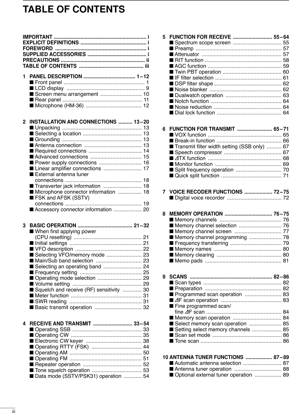
![121PANEL DESCRIPTION1!2 ANTENNA CONNECTOR 1 [ANT1]!3 ANTENNA CONNECTOR 2 [ANT2] (pgs. 13, 14)Accept a 50 Ωantenna with a PL-259 connector.When using an optional AH-4 HF/50 MHz AUTO-MATIC ANTENNA TUNER or AH-3 HF AUTOMATIC AN-TENNA TUNER, connect it to the [ANT1] connector.The internal antenna tuner activates for [ANT2] anddeactivates for [ANT1] when connecting the AH-4 orAH-3.!4 GROUND TERMINAL [GND] (pgs. 13, 14)Connect this terminal to a ground to prevent electri-cal shocks, TVI, BCI and other problems.■Microphone (HM-36)qUP/DOWN SWITCHES [UP]/[DN]Change the selected readout frequency or memorychannel.•Continuous pushing changes the frequency or memorychannel number continuously.•While pushing [XFC], the transmit readout frequency canbe controlled while in spilt frequency operation.•The [UP]/[DN] switch can simulate a key paddle. Presetin the keyer set mode. (p. 43)wPTT SWITCHPush and hold to transmit; release to receive.qw++qwertyui4700p4700p100.33MICROPHONEMICELEMENT2k470DOWN UPPTT RECEIVETRANSMITMICROPHONE CABLE MICROPHONE PLUG• HM-36 SCHEMATIC DIAGRAM](https://usermanual.wiki/ICOM-orporated/217800/User-Guide-467148-Page-17.png)
![2INSTALLATION AND CONNECTIONS■UnpackingAfter unpacking, immediately report any damage to thedelivering carrier or dealer. Keep the shipping cartons.For a description and a diagram of accessory equip-ment included with the IC-756PROIII, see ‘Suppliedaccessories’ on p. i of this manual.■Selecting a locationSelect a location for the transceiver that allows ade-quate air circulation, free from extreme heat, cold, orvibrations, and away from TV sets, TV antenna ele-ments, radios and other electromagnetic sources.The base of the transceiver has an adjustable standfor desktop use. Set the stand to one of two angles de-pending on your operating conditions.■GroundingTo prevent electrical shock, television interference(TVI), broadcast interference (BCI) and other prob-lems, ground the transceiver through the GROUNDterminal on the rear panel.For best results, connect a heavy gauge wire or strapto a long earth-sunk copper rod. Make the distance be-tween the [GND] terminal and ground as short as pos-sible.RWARNING: NEVER connect the [GND]terminal to a gas or electric pipe, since the connec-tion could cause an explosion or electric shock.■Antenna connectionFor radio communications, the antenna is of critical im-portance, along with output power and sensitivity. Se-lect antenna(s), such as a well-matched 50 Ωantenna,and feedline. 1.5:1 or better of Voltage Standing WaveRatio (VSWR) is recommended for your desired band.Of course, the transmission line should be a coaxialcable.When using 1 antenna, use the [ANT1] connector.CAUTION: Protect your transceiver from lightningby using a lightning arrestor.Antenna SWREach antenna is tuned for a specified frequencyrange and SWR may be increased out-of-range.When the SWR is higher than approx. 2.0:1, thetransceiver’s power drops to protect the final transis-tor. In this case, an antenna tuner is useful to matchthe transceiver and antenna. Low SWR allows fullpower for transmitting even when using the antennatuner. The IC-756PROIII has an SWR meter to mon-itor the antenna SWR continuously.PL-259 CONNECTOR INSTALLATION EXAMPLE30 mm ≈9⁄8in 10 mm ≈3⁄8in 1–2 mm ≈1⁄16 in30 mm10 mm (soft solder)10 mm1–2 mmsolder solderSoftsolderCoupling ringSlide the coupling ring down. Strip the cable jacket and soft solder.Slide the connector body on and solder it.Screw the coupling ring onto the connector body.Strip the cable as shown at left. Soft sol-der the center con-ductor.qwer13](https://usermanual.wiki/ICOM-orporated/217800/User-Guide-467148-Page-18.png)
![214INSTALLATION AND CONNECTIONS2■Required connections•Front panel•Rear panelSWRSCOMPALCPo0101025 50 10020101.5 23159+20 +40 +60dBdBRIT/ TXTXF-1SSBF-2 F-3 F-4 F-5CW/RTTYAM/FM FILTER EXIT/SET1234567890ENTNOTCHPBT CLRLOCKTXRXNOTCHTWIN PBTCW PITCHREC/PLAYLOCK/SPEECHRIT CLEARSPLITMP-W MP-RDUALWATCHVFO/MEMOMAIN/SUBM.SCOPECHANGE1.8 3.5 710 14 1821 24 28GENE50 F-INPMWM-CLTSXFCTIMERPOWERTRANSMITPHONESELEC-KEYMICTUNER MONITOR NB NRAF BAL NRRF/SQLMIC GAIN RF POWER COMP KEY SPEEDBK-IN DELAYHF/50MHz TRANSCEIVERCW KEYA straight key can be used when the internal electronic keyer is turned OFF in keyer set mode. (p. 43)MICROPHONES (p. 114)SM-20HM-36GROUND (p. 13)Use the heaviest gauge wire or strap available and make the connection as short as possible.Grounding prevents electrical shocks, TVI and other problems.ANTENNA 1, 2 (p. 13)[Example]: ANT1 for 1.8–18 MHz bandsANT2 for 21–50 MHz bandsDC POWER SUPPLY (p.16)STRAIGHT KEYPS-125](https://usermanual.wiki/ICOM-orporated/217800/User-Guide-467148-Page-19.png)
![152INSTALLATION AND CONNECTIONS■Advanced connections•Front panel•Rear panelSWRSCOMPALCPo0101025 50 10020101.5 23159+20 +40 +60dBdBRIT/ TXTXF-1SSBF-2 F-3 F-4 F-5CW/RTTYAM/FM FILTER EXIT/SET1234567890ENTNOTCHPBT CLRLOCKTXRXNOTCHTWIN PBTCW PITCHREC/PLAYLOCK/SPEECHRIT CLEARSPLITMP-W MP-RDUALWATCHVFO/MEMOMAIN/SUBM.SCOPECHANGE1.8 3.5 710 14 1821 24 28GENE50 F-INPMWM-CLTSXFCTIMERPOWERTRANSMITPHONESELEC-KEYMICTUNER MONITOR NB NRAF BAL NRRF/SQLMIC GAIN RF POWER COMP KEY SPEEDBK-IN DELAYHF/50MHz TRANSCEIVERHEADPHONESMICThe AFSK modulation signal can be input from [MIC]. (p. 19)ANTENNA 1, 2 (pgs. 17, 18)Connects a linear amplifier, antenna selector, etc.EXTERNAL SPEAKER (p. 114)ACC SOCKETS (pgs. 19, 20)RX ANTENNATRANSVERTER (p. 18)Connects a transverter for V/UHF band use.SP-23AH-4/AH-3 (p. 18)AH-2b[REMOTE] (p. 109)Used for computer control and transceive operation.[SEND], [ALC] (p. 17)Used for connecting a non-Icom linear ampli-fier.When using the AH-4/AH-3, it must be connected to the [ANT1] connector.](https://usermanual.wiki/ICOM-orporated/217800/User-Guide-467148-Page-20.png)
![162INSTALLATION AND CONNECTIONS2■Power supply connectionsUse the optional PS-125 DC power supply with a 25 Acapacity when operating the transceiver with ACpower. Refer to the diagrams below.CAUTION: Before connecting the DC powercable, check the following important items. Makesure:•The [POWER] switch is OFF.•Output voltage of the power source is 12–15 Vwhen you use a non-Icom power supply.•DC power cable polarity is correct.Red : positive +terminalBlack : negative _terminalCONNECTING A DC POWER SUPPLYto DC power socketA DC power supplyAC outletAC cable30 A fusesSuppliedDC power cable13.8 V; at least 23 ABlack_Red+TransceiverCONNECTING A VEHICLE BATTERY12 VbatterySuppliedDC power cable+ red_ blackCrimpSolderGrommetNOTE: Use terminals forthe cable connections.RWARNING NEVER con-nect to a battery without suppliedDC fuses, otherwise a fire hazardmay occur.NEVER connect the transceiverdirectly to a 24 V battery.IMPORTANT! Detailed installationnotes for Icom mobile transceivers tobe fitted into vehicles are available.Contact your Icom dealer or distribu-tor.CONNECTING PS-125 DC POWER SUPPLYPS-125Connect to an AC outletusing the supplied AC cable.DC power cableDC powersocketTransceiver](https://usermanual.wiki/ICOM-orporated/217800/User-Guide-467148-Page-21.png)
![172INSTALLATION AND CONNECTIONS■Linear amplifier connections Use the [ANT1] connector when connecting a linearamplifier.CONNECTING THE IC-PW1Turn OFF the transceiver’s antenna tuner while tuning the IC-PW1’s tuner.To anantenna ACC-1ANTANT2 ANT1 ACC(2)INPUT1INPUT2REMOTEEXCITER11&2GNDGNDIC-PW1AC outlet(Non-European versions: 100–120/220–240 V European version : 230 V)Ground TransceiverREMOTERemote control cable (supplied with the IC-PW1)ACC cable (supplied with the IC-PW1)Be sure to connect the cableto the 7-pin ACC(2) jack.Coaxial cable(supplied with the IC-PW1)Coaxial cable(optional)Connect[INPUT2]if necessaryCONNECTING A NON-ICOM LINEAR AMPLIFIERRWARNING:Set the transceiver output power and linear amplifierALC output level referring to the linear amplifier in-struction manual.The ALC input level must be in the range 0 V to –4 V,and the transceiver does not accept positive voltage.Non-matched ALC and RF power settings could causea fire or ruin the linear amplifier.The specifications for the SEND relay are 16 V DC0.5 A. If this level is exceeded, a large external relaymust be used.RF OUTPUT RF INPUTALCSEND50 ‰ coaxial cableTransceiverANT1 ALC SENDTo an antennaNon-Icom linear amplifier](https://usermanual.wiki/ICOM-orporated/217800/User-Guide-467148-Page-22.png)
![182INSTALLATION AND CONNECTIONS2■External antenna tuner connectionCONNECTING THE AH-4/AH-3The AH-4 or AH-3 must be connected to [ANT1].Coaxial cable (from the AH-4 or AH-3)ANT1 Control cableTransceiver Ground AH-4 or AH-3Long wire or optional AH-2b(Front panel view)CAUTION: DO NOT short pin 2 to ground as thiscan damage the internal 8 V regulator.NOTE: DC voltage is applied to pin 1 for micro-phone operation. Take care when using a non-Icommicrophone.y GND (PTT ground)t PTTr Main readout squelch switchq Microphone inputw +8 V DC outpute Frequency up/downu GND (Microphone ground)i Main readout AF output (varies with [AF]/[BAL])[MIC] FUNCTION DESCRIPTIONPin No.w+8 V DC output Max. 10 mAeFrequency up GroundFrequency down Ground through 470 ΩrSquelch open “Low” levelSquelch closed “High” level■Microphone connector informationWhen 2 to 13.8 V is applied to pin 6 of [ACC(2)], the[XVERT] jack is activated for transverter operationand the antenna connectors do not receive or trans-mit any signals. (p. 20)While receiving, the [XVERT] jack can be activated asan input terminal from an external transverter.While transmitting, the [XVERT] jack outputs signalsof the displayed frequency at –20 dBm (22 mV) assignals for the external transverter.Transverter jack■Transverter jack information](https://usermanual.wiki/ICOM-orporated/217800/User-Guide-467148-Page-23.png)
![192INSTALLATION AND CONNECTIONSAF inputGround (GND)PTTSQUELCH input*RTTY keying* Connect the SQUELCH line when required.Terminal unit (TU) orTerminal Node Controller (TNC)[ACC(1)] socket(Rear panel view)12345678AFSK outputAF inputGround (GND)Ground (GND)PTTSQUELCH input** Connect the SQUELCH line when required.Terminal Node Controller (TNC)or Scan converter[ACC(1)] socket(Rear panel view)12345678AF inputGround (GND)AFSK outputPTTSQUELCH input** Connect the SQUELCH line when required.Terminal Node Controller (TNC)or Scan converter[MIC] connector(Front panel view)12345678■FSK and AFSK (SSTV) connectionsTo connect a terminal unit, TNC or scan converter,refer to the diagram below.For RTTY operation:Narrow filter settings may not pass RTTY signals.Be sure to select the appropriate IF filter settingscorresponding to the signal width. (p. 61)FSK (RTTY) connectionUse RTTY mode for operationAFSK and SSTV connectionsUse SSB or FM mode for operationAFSK and SSTV connections via microphone connectorUse SSB or FM mode for operationWhen connected to the [MIC] connector, [MICGAIN] and [AF] control adjustment is required.](https://usermanual.wiki/ICOM-orporated/217800/User-Guide-467148-Page-24.png)
![202INSTALLATION AND CONNECTIONS■Accessory connector informationIf the CW side tone level limit or beep level limit is inuse, the CW side tone or beep tone decreases fromthe fixed level when the [AF] control is rotated abovea specified level, respectively. (p. 94)ACC (1)PIN No.NAME DESCRIPTION SPECIFICATIONS12345678“High” level : More than 2.4 V1RTTY Controls RTTY keying “Low” level : Less than 0.6 VOutput current : Less than 2 mA2GND Connects to ground. Connected in parallel with ACC(2) pin 2.Input/output pin. Ground level : –0.5 V to 0.8 V3SEND Goes to ground when transmitting. Output current : Less than 20 mAWhen grounded, transmits. Input current (Tx) : Less than 200 mAConnected in parallel with ACC(2) pin 3.4MOD Modulator input. Input impedance : 10 kΩConnects to a modulator. Input level : Approx. 100 mV rmsAF detector output. Output impedance : 4.7 kΩ5AFFixed, regardless of [AF] position Output level : 100–300 mV rmsin default settings. (see notes below)6SQLS Squelch output. SQL open : Less than 0.3 V/5 mAGoes to ground when squelch opens.SQL closed : More than 6.0 V/100 µA713.8 V 13.8 V output when power is ON. Output current : Max. 1 AConnected in parallel with ACC(2) pin 7.Control voltage : –4 V to 0 V8ALC ALC voltage input. Input impedance : More than 10 kΩConnected in parallel with ACC(2) pin 5.ACC (2)PIN No.NAME DESCRIPTION SPECIFICATIONS123456718VRegulated 8 V output. Output voltage : 8 V ±0.3 VOutput current : Less than 10 mA2GND Same as ACC(1) pin 2.3SEND Same as ACC(1) pin 3.4BAND Band voltage output. Output voltage : 0 to 8.0 V(Varies with amateur band)5ALC Same as ACC (1) pin 8.6TRVActivates [XVERT] input/output Input impedance : More than 10 kΩwhen “HIGH” voltage is applied. Input voltage : 2 to 13.8 V713.8 VSame as ACC(1) pin 7.Rear panel viewRear panel view2](https://usermanual.wiki/ICOM-orporated/217800/User-Guide-467148-Page-25.png)
![Before first applying power, make sure all connectionsrequired for your system are complete by referring toSection 2. Then, reset the transceiver using the follow-ing procedure.Resetting CLEARS all programmed contents inmemory channels and returns programmed valuesin set mode to default values.qMake sure the transceiver power is OFF.wWhile pushing [M-CL] and [F-INP], push [POWER]to turn power ON.•The internal CPU is reset.•A/D convertor calibration of the DSP unit starts and ittakes 10 sec.•The transceiver displays its initial VFO frequencies whenresetting is complete.eCorrect the set mode settings after resetting, if de-sired.■Initial settingsAfter resetting the transceiver, set controls andswitches as shown in the figure below.Under cooler temperatures, the LCD may appeardark and unstable after turning power ON. This isnormal and does not indicate any equipment mal-function.CW : Max. clockwiseCCW : Max. counterclockwise■When first applying power (CPU resetting)[POWER] [F-INP] [M-CL]*1 FAST in FM mode.*2 Appears in some modes.[POWER]: OFF[TUNER], [MONITOR],[NB], [NR]: OFF[AF]: Max. CCW[RF/SQL]: 12 o clock[MIC GAIN]: 10—12 o clock[RF POWER]: Max. CW[ANT]: 1[METER]: Po[P.AMP]: 1[ATT]: OFF [PBT CLR]: OFF[NOTCH]: OFF[BAL]: Center [AGC]: MID*1[LOCK]: OFF[COMP]*2: OFF WIDE;[1/4],*2 [TONE]*2: OFF [VOX],*2 [BK-IN],*2[RTTY FIL]*2: OFFTurn power ON, then check the display. If any of thefollowing indicators appear, turn them OFF as follows:•Quick tuning step indicator “▼”: Push [TS].•1 Hz frequency readout : Push [TS] for 2 sec.(while quick tuningstep is OFF)•RIT indicator “ ” : Push [RIT].•∂TX indicator “ ” : Push [∂TX].•Split indicator “ ” : Push [SPLIT].•Dualwatch indicator “ ” : Push[DUAL WATCH].•Twin peak filter indicator “ ”: Push [RTTY FIL].•Auto notch indicator “ ” : Push [NOTCH].•Manual notch indicator “ ” : Push [NOTCH].MNANTPFTPFDUAL-WDUAL-WSPLITSPLIT∂TXTXRITRIT321BASIC OPERATIONS](https://usermanual.wiki/ICOM-orporated/217800/User-Guide-467148-Page-26.png)
![223BASIC OPERATION3■VFO descriptionVFO is an abbreviation of Variable Frequency Oscilla-tor, and traditionally refers to an oscillator.The transceiver’s VFO is somewhat different. The VFOof the IC-756PROIII acts like a computer’s window andcan show one frequency and one operating mode.You can call up a desired frequency to the VFO withthe keypad, memo pad-read switch (see p. 81) or thememory transfer function (see p. 79). You can alsochange the frequency with the tuning dial and selectthe operating mode with the mode switches.During dualwatch or split frequency operation, the subVFO is functional (non-outline, non-spotted, larger fre-quency characters). While pushing [XFC] during splitfrequency operation, you can change the transmitreadout frequency with the keypad, memo pad-readswitch or the memory transfer function.METERPoANT1BWBW 2.4k2.4k SFTSFT 0VFOVFO FIL2FIL2USBUSBqw:ppTXTX1CWCWqr.qpp.pp21.076.5021.076.50SelectTUNING DIALMEMORYCHANNELMODESWITCHESMEMO PADKEYPAD(BAND KEY)TransferTransfer TransferChange21.295 MHz 28.025 MHz 7.001 MHz•Differences between VFO mode and memory modeVFO MODEVFO shows a frequency and operating mode. If thefrequency or operating mode is changed, the VFOautomatically memorizes the new frequency or newoperating mode.When a VFO is selected from another band or mem-ory mode, the frequency and operating mode lastused for that VFO appear.[EXAMPLE]MEMORY MODE (pgs. 76–80)Each memory channel shows a frequency and oper-ating mode like a VFO. Even if the frequency or modeis changed, the memory channel does not memorizethe new frequency or operating mode.When the memory channel is selected from anothermemory channel or VFO mode, the memorized fre-quency and operating mode appear.[EXAMPLE]METERMETERPoPoANTANT1METERMETERPoPoANTANT1METERMETERPoPoANTANT1METERMETERPoPoANTANT1BWBW 2.4k2.4k SFTSFT 0VFOVFO FIL2FIL2USBUSBqw:ppTXTX1CWCWqr.qwe.pp21.076.5021.076.50BWBW 500 500 SFTSFT 0BPFBPF1FIL2FIL2CWCWqw:ppTXTXVFOVFO USBUSBwq.puy.tp14.123.0014.123.00BWBW 2.4k2.4k SFTSFT 0VFOVFO FIL2FIL2USBUSBqw:ppTXTX1CWCWqr.qwe.pp21.076.5021.076.50BWBW 2.4k2.4k SFTSFT 0VFOVFO FIL2FIL2USBUSBqw:ppTXTX1CWCWqr.qpp.pp21.076.5021.076.50BWBW 2.4k2.4k SFTSFT 0FIL2FIL2USBUSBqw:ppTXTXVFOVFO USBUSBqr.qpp.pp14.100.0014.100.00BWBW 2.4k2.4k SFTSFT 0FIL2FIL2USBUSBqw:ppTXTXVFOVFO USBUSBwq.wrt.pp14.100.0014.100.00BWBW 2.4k2.4k SFTSFT 0FIL2FIL2USBUSBqw:ppTXTXVFOVFO USBUSBqr.qwe.pp14.100.0014.100.00BWBW 2.4k2.4k SFTSFT 01FIL2FIL2USBUSBqw:ppTXTXVFOVFO USBUSBqr.qpp.pp14.100.0014.100.00112121METERMETERPoPoANTANT1METERMETERPoPoANTANT1METERMETERPoPoANTANT1METERMETERPoPoANTANT1VFO is selected.The frequency is changed.Memory mode is selected.VFO is selected again.Memory channel 1 is selected.The frequency is changed.Another memory channel is selected.Memory channel 1 is selected again.Changed frequency (14.123 MHz) appears. Changed frequency (14.123 MHz) does not appear andmemorized frequency (14.100 MHz) appears instead.](https://usermanual.wiki/ICOM-orporated/217800/User-Guide-467148-Page-27.png)
![233BASIC OPERATION➥Push [VFO/MEMO] to switch between VFO andmemory modes.•“VFO” appears when VFO mode, or the selected mem-ory channel number appears when memory mode isselected beside the frequency readout.•Pushing [VFO/MEMO] for 1 sec. transfers the contentsof the selected memory channel to VFO mode. (p. 79)SFTSFT 0FIL2FIL2CWCWqw:ppTXTXUSBUSBqr.qot.pp14.100.0014.100.00BPFBPF1VFOVFOBWBW 500 500 SFTSFT 0FIL2FIL2USBUSBqw:ppTXTXCWCWqr.qpp.pp14.195.0014.195.00VFOVFO1BWBW 2.4k2.4kANTANT1METERMETERPoPoANTANT1METERMETERPoPoVFO indicatorMemory channel number[VFO/MEMO]■Selecting VFO/memory mode➥Push [MAIN/SUB] to select access to the main orsub readout.•The sub readout frequency is displayed in outline ormesh font. The sub readout functions only during splitoeration or dualwatch.[MAIN/SUB]■Main/Sub band selection](https://usermanual.wiki/ICOM-orporated/217800/User-Guide-467148-Page-28.png)
![243BASIC OPERATION3The triple band stacking register provides 3 memoriesin one band. 3 sets of a frequency and operating modeon each band are automatically stored when used.If a band key is pushed once, the frequency and oper-ating mode last used are called up. When the key ispushed again, another stored frequency and operatingmode are called up.This function is convenient when you operate 3 oper-ating modes on one band. For example, one registeris used for a CW frequency, another for an SSB fre-quency and the other one for an RTTY frequency.See the table below for a list of the band available andthe default settings for each band.Band keys■Selecting an operating bandBAND REGISTER 1 REGISTER 2 REGISTER 31.8 MHz 1.900000 MHz CW 1.910000 MHz CW 1.915000 MHz CW3.5 MHz 3.550000 MHz LSB 3.560000 MHz LSB 3.580000 MHz LSB7MHz 7.050000 MHz LSB 7.060000 MHz LSB 7.020000 MHz CW10 MHz 10.120000 MHz CW 10.130000 MHz CW 10.140000 MHz CW14 MHz 14.100000 MHz USB 14.200000 MHz USB 14.050000 MHz CW18 MHz 18.100000 MHz USB 18.130000 MHz USB 18.150000 MHz USB21 MHz 21.200000 MHz USB 21.300000 MHz USB 21.050000 MHz CW24 MHz 24.950000 MHz USB 24.980000 MHz USB 24.900000 MHz CW28 MHz 28.500000 MHz USB 29.500000 MHz USB 28.100000 MHz CW50 MHz 50.100000 MHz USB 50.200000 MHz USB 51.000000 MHz FMGeneral 15.000000 MHz USB 15.100000 MHz USB 15.200000 MHz USBqPush [(14)5], then select a frequency and an oper-ating mode.•Frequency and operating mode are memorized in thefirst band stacking register.wPush [(14)5] again, then select another frequencyand operating mode.•This frequency and operating mode are memorized inthe second band stacking register.ePush [(14)5] again, then select another frequencyand operating mode.•This frequency and operating mode are memorized inthe third band stacking register.•When a fourth frequency and operating mode are se-lected on a band, the first register set in step q, is overwritten.[Example]: 14 MHz band1.8 3.5 710 14 1821 24 28GENE•501234567890F-INPENTDDUsing the band stacking registers](https://usermanual.wiki/ICOM-orporated/217800/User-Guide-467148-Page-29.png)
![253BASIC OPERATIONThe transceiver has several tuning methods for conve-nient frequency tuning.■Frequency settingDDDirect frequency entry with the keypadDDTuning with the tuning dialqPush the desired band key on the keypad 1–3times.•3 different frequencies can be selected on each bandwith the band key. (See previous page “Using the bandstacking register.”)wRotate the tuning dial to set the desired frequency.If the dial lock function is activated, the lock indica-tor lights, and the tuning dial does not function. Inthis case, push [LOCK/SPEECH] to deactivate thelock function.METERPoANT1BWBW2.4k2.4kSFTSFT0VFOVFOFIL2FIL2USBUSBqw:ppTXTX1CWCWwq.wot.pp21.076.5021.076.50METERPoANT1BWBW2.4k2.4kSFTSFT0VFOVFOFIL2FIL2USBUSBqw:ppTXTX1CWCWwq.wpp.pp21.076.5021.076.50Band keysTuning dialThe transceiver has a keypad for direct frequencyentry as described right.qPush [(F-INP)ENT].•“ ” appears.wInput the desired frequency.•Push [(GENE)•] to input “• (decimal point)” between theMHz units and kHz units.ePush [(F-INP)ENT] to set the input frequency.•To cancel the input, push [MAIN/SUB] instead of[(F-INP)ENT].[EXAMPLE]KeypadF-INPENT21.280 21.24514.025 MHz1 04 2• 508 7• 2 5ENT7 0• 6F-INP ENT2 4• 5F-INP ENT18.0725 MHz1F-INP706 kHzF-INP ENT• 155.100 MHzF-INP ENT77.000 MHz](https://usermanual.wiki/ICOM-orporated/217800/User-Guide-467148-Page-30.png)
![263BASIC OPERATION3DDQuick tuning stepThe operating frequency can be changed in kHzsteps (0.1, 1, 5, 9, 10, 12.5, 20 or 25 kHz selectable)for quick tuning.qPush [TS] momentarily to turn the quick tuningfunction ON.•“Z” appears when the quick tuning function ON.wRotate the tuning dial to change the frequency inprogrammed kHz steps.ePush [TS] again to turn the quick tuning functionOFF.•“Z” disappears.rRotate the tuning dial for normal tuning if desired.BWBW 2.4k2.4k SFTSFT 0FIL2FIL2qw:ppTXTXCWCWqr.qpp.pp21.076.5021.076.50VFOVFOUSBUSB1METERPoANT1Quick tuning indicator[TS]Tuning dialDDSelecting “kHz” stepqPush [TS] momentarily to turn the quick tuningstep ON.•“Z” appears when the quick tuning function ON.wPush [TS] for 1 sec. to enter the tuning step set-ting display.•Selected tuning steps for all modes appear.eSelect the desired operating mode.rRotate the tuning dial to select the desired tuningstep from 0.1, 1, 5, 9, 10, 12.5, 20 or 25 kHz.•Push [(F-3)DEF] to return to the default setting, if de-sired.tRepeat steps eand rto select quick tuningsteps for other modes, if desired.yPush [EXIT/SET] to exit the setting display.DEFDEFTSTSFMFMAMAM1010(kHz)(kHz)1111SSBSSB CWCW RTTYRTTYVOXVOXOFFOFFCOMPCOMPOFFOFFWIDEWIDEAGCAGCMIDMID[TS]Tuning dialMode selection](https://usermanual.wiki/ICOM-orporated/217800/User-Guide-467148-Page-31.png)
![273BASIC OPERATIONDDSelecting 1 Hz stepThe minimum tuning step of 1 Hz can be used for finetuning.qPush [TS] to turn OFF the quick tuning step.•“▼” does not appear.wPush [TS] for 1 sec. to turn the 1 Hz tuning stepON and OFF.•RIT and/or ∂TX also functions in 1 Hz tuning step whenused.SCOPESCOPE VOICEVOICE MEMORYMEMORY SCANSCANBWBW 2.4k2.4k SFTSFT 0FIL2FIL2USBUSBqw:pp1TXTXVFOVFO1USBUSBUSBUSBUSBUSBFIL2FIL2qr.qot.pppqr.wpt.ppp14.100.0014.100.0014.100.0014.100.00VFOVFOATTATT0FF0FFMETERMETERPoPoP.AMPP.AMP1VOXVOXOFFOFFCOMPCOMPOFFOFFWIDEWIDEAGCAGCMIDMIDANTANT11 Hz step indicator[TS]Tuning dialDD1⁄4tuning function (SSB data/CW/RTTY only)While operating in SSB data/CW/RTTY, the 1⁄4tuningfunction is available for critical tuning. Dial rotation isreduced to 1⁄4of normal when the 1⁄4function is inuse.➥Push [1/4] to toggle the 1⁄4function ON and OFF.1/4OFF1/4ON1⁄4 tuning function OFF 1⁄4 tuning function ON[1/4]](https://usermanual.wiki/ICOM-orporated/217800/User-Guide-467148-Page-32.png)
![283BASIC OPERATION3DDAuto tuning step functionWhen rotating the tuning dial rapidly, the tuning speedaccelerated automatically as selected.qPush [EXIT/SET] several times to close a multi-function screen, if necessary.wPush [EXIT/SET] for 1 sec. to select the set modemenu screen.ePush [(F-5)OTHERS] to enter miscellaneous (oth-ers) set mode.rPush [(F-1)Y] or [(F-2)Z] to select “MAIN DIALAuto TS.”tRotate tuning dial to select the desired conditionfrom high, low and OFF.•High: Approx. 5 times faster•Low: Approx. twise faster•OFF: Auto tuning step is turned OFFyPush [EXIT/SET] to exit the set mode.OTHERS OTHERS SETSETéèDEFDEF WIDEWIDEBK-INBK-INOFFOFF1/41/4OFFOFFAGCAGCMIDMIDMemopadNumbers OFFMAIN DIAL Auto TS HIGHMIC UP/Down Speed HIGHQuick RIT/∂TX Clear OFFSSB/CW Synchronous Tuning OFFCW Normal Side LSBExternal Keypad AutoTuning dial[(F-2)Z] [(F-5)OTHERS][(F-1)Y] [EXIT/SET]DDBand edge warning beepWhen selecting a frequency, that lies outsideof aband’s specified frequency range, a warning beepsounds.This function can be turned OFF in set mode, if de-sired.qPush [EXIT/SET] several times to close a multi-function screen, if necessary.wPush [EXIT/SET] for 1 sec. to select the set modemenu screen.ePush [(F-5)OTHERS] to enter miscellaneous (oth-ers) set mode.rPush [(F-1)Y] or [(F-2)Z] to select “Beep (Bandedge).”tRotate tuning dial to turn the band edge warningbeep ON and OFF.yPush [EXIT/SET] to exit the set mode.OTHERS OTHERS SETSETéèDEFDEF WIDEWIDEBK-INBK-INOFFOFF1/41/4OFFOFFAGCAGCMIDMIDBeep(Confirmation) ONBeep(Band Edge) ONRF/SQL Control RF+SQLQuick Dualwatch ONQuick SPLIT ONFM SPLIT Offset(HF) -0.100MHzFM SPLIT Offset(50M) -0.100MHzTuning dial[(F-2)Z] [(F-5)OTHERS][(F-1)Y] [EXIT/SET]](https://usermanual.wiki/ICOM-orporated/217800/User-Guide-467148-Page-33.png)
![293BASIC OPERATION■Operating mode selectionSSB (LSB/USB), CW, CW-R (CW reverse), RTTY,RTTY-R (RTTY reverse), AM and FM. Data modes ofSSB, AM and FM are also available in the IC-756PROIII. Select the desired operation mode as fol-lows.To select a mode of operation, push the desired modeswitch momentarily. Push the switch again to togglebetween USB and LSB, CW/CW-R and RTTY/RTTY-R, AM and FM, if necessary. Push the switch for1sec. to toggle between CW and CW-R, RTTY andRTTY-R, or to select data mode, if necessary.See the diagram below left for the order of selection.Microphone signals are muted when data mode isselected.•Selecting SSB mode➥Push [SSB] to select USB or LSB.•USB is selected first when above 10 MHz; or LSB isselected first when below 10 MHz operation.(USB is selected when 5 MHz band is selected for theUSA version.)•After USB or LSB is selected, push [SSB] to toggle be-tween USB and LSB.•After USB or LSB is selected, push [SSB] for 1 sec. toselect USB-D or LSB-D mode, respectively.•Selecting CW/RTTY mode➥Push [CW/RTTY] to select CW or RTTY.•After CW or RTTY is selected, push [CW/RTTY] to tog-gle between CW and RTTY.•After CW or RTTY is selected, push [CW/RTTY] for1sec. to toggle between CW and CW reverse, or,RTTY and RTTY reverse mode, respectively.•Selecting AM/FM mode➥Push [AM/FM] to select AM or FM.•After AM or FM is selected, push [AM/FM] to toggle be-tween AM and FM.•After AM or FM is selected, push [AM/FM] for 1 sec. toselect AM-D or FM-D mode, respectively.Mode selectionSSBCW/RTTYAM/FMUSB-D USBCW-R CWAM-D AMPush mode switch for 1 sec. Push mode switchmomentarily.LSB LSB-DRTTY RTTY-RFM FM-D■Volume setting➥Rotate [AF] control clockwise to increase; counter-clockwise to decrease the audio output level.•Set a suitable audio level.Audio outputincreasesAudio outputdecreases[AF]](https://usermanual.wiki/ICOM-orporated/217800/User-Guide-467148-Page-34.png)
![303BASIC OPERATION3■Squelch and receive (RF) sensitivityAdjusts the RF gain and squelch threshold level. Thesquelch removes noise output from the speaker(closed position) when no signal is received. •The squelch is particularly effective for FM. It is also avail-able for other modes.•12 to 1 o’clock position is recommended for any setting ofthe [RF/SQL] control.•The control can be set as ‘Auto’ (RF gain control in SSB,CW and RTTY; squelch control in AM and FM) or squelchcontrol (RF gain is fixed at maximum) in set mode as fol-lows. (p. 98)Adjusting RF gain (Receive sensitivity)Normally, [RF/SQL] is set to the 11 o’clock position.Rotate [RF/SQL] to the 11 o’clock position for maxi-mum sensitivity. •Rotating counterclockwise from the maximum position re-duces sensitivity.•The S-meter indicates receive sensitivity.Adjusting squelch (Removing non-signal noise)Rotate [RF/SQL] clockwise when receiving no signal,until the noise just disappears.•[RX] indicator light goes out.•Rotating [RF/SQL] past the threshold point invokes the S-meter squelch— this allows you to set a minimum signallevel needed to open the squelch.•When setting as RF gain/squelch control•When functioning as RF gain control(Squelch is fixed open; SSB, CW, RTTY only)•When functioning as squelch control(RF gain is fixed at maximum.)While rotating the RF gain control, noise may beheard. This comes from the DSP unit and does notindicate an equipment malfunction.Squelch is open.S-meter squelchS-meter squelchthresholdNoise squelch threshold (FM mode)Shallow DeepNoise squelch (FM mode)Minimum RF gainAdjustablerangeMaximum RF gainRecommended levelRF gain adjustablerangeMaximum RF gainS-meter squelchNoise squelch (FM mode)Squelch is open.[RF/SQL]SET MODE OPERATIONRF+SQLCan be used in all modes.(default)Functions as noise squelch or S-metersquelch in AM and FM modes; S-meter squelch only in other modes.SQL Operates as a squelch control.•RF gain is fixed at maximum sensitivity.Operates as an RF gain control inSSB, CW and RTTY modes.AUTO •Squelch is fixed open.Operates as a squelch control in AMand FM modes.•RF gain is fixed at maximum sensitivity.](https://usermanual.wiki/ICOM-orporated/217800/User-Guide-467148-Page-35.png)
![313BASIC OPERATION■Meter functionThe transceiver has 4 transmit meter functions foryour convenience. Select the desired meter with the[METER] switch.•Analog transmit meter➥Push [METER] to select RF power (Po), SWR, ALCor compression level (COMP).In addition, the transceiver can display the multi-func-tion digital meter in the LCD display, which displaysall transmit meters simultaneously.•Multi-function digital meterqPush [METER] for 1 sec. to turn the multi-functiondigital meter ON.wPush [(F-1)P-HOLD] to toggle the peak level holdfunction ON or OFF.•“P-HOLD” appears on the window title when the peaklevel hold function is turned ON.ePush [METER] for 1 sec. or push [EXIT/SET] toturn the multi-function digital meter OFF.P-HOLDP-HOLDBWBW 2.4k2.4k SFTSFT 0FIL2FIL2USBUSBqw:ppTXTXVFOVFO USBUSBUSBUSBUSBUSBFIL2FIL2qr.qot.ppqr.wpt.pp14.100.0014.100.0014.100.0014.100.0011VFOVFO.1...3...5...7...9..1...3...5...7...9.....+20+20......+40+40......+60dB+60dB0∑∑∑∑∑∑∑∑∑∑∑∑∑∑∑∑∑∑∑∑∑∑2525∑∑∑∑∑∑∑∑∑∑∑∑∑∑∑∑∑∑∑50 ∑∑∑∑∑∑∑∑∑∑∑∑∑∑∑∑∑∑∑∑∑∑∑∑∑∑∑∑∑∑∑∑∑∑∑∑∑∑ 100%100%11.51.5 22.52.5 3SPoPoALCALCCOMPCOMPSWRSWRP-HOLDP-HOLD MULTI-FUNCTION METERMULTI-FUNCTION METERANTANT1COMPCOMPOFFOFFWIDEWIDEMETERMETERPoPoP.AMPP.AMP1AGCAGCMIDMIDATTATTOFFOFFVOXVOXOFFOFF0 5 1010 1515 2020 dB[METER] switchDISPLAY MEASUREMENTINDICATIONPoIndicates the relative RF output power in %.SWR Indicates the SWR over the transmissionline.ALCIndicates the ALC level. When the metermovement shows the input signal level ex-ceeds the allowable level, the ALC limitsthe RF power. In such cases, reduce the[MIC GAIN] control.COMP Indicates the compression level when thespeech compressor is in use.■SWR readingThe SWR meter indicates the SWR over the trans-mission line in all modes.qPush [TUNER] to turn the antenna tuner OFF.wPush [METER] several times to select the Pometer.ePush [CW/RTTY] once or twice to select RTTYmode.rPush [TRANSMIT].tRotate [RF POWER] clockwise past the 12 o’clockposition for more than 30 W output power (30%).yPush [METER] once to select the SWR meter asthe transmit meter.uRead the SWR on the SWR meter.The built-in antenna tuner matches the transmitterto the antenna when the SWR is lower than 3 : 1.SWRSCOMPALCPo0101025 50 10020101.5 23159+20 +40 +60dBdBSWR meterLess than 1.5:1](https://usermanual.wiki/ICOM-orporated/217800/User-Guide-467148-Page-36.png)
![323BASIC OPERATION3■Basic transmit operationDDTransmittingBefore transmitting, monitor your selected operatingfrequency to make sure transmitting won’t cause in-terference to other stations on the same frequency. qPush [TRANSMIT] or [PTT] (microphone) to trans-mit.•The main band’s [TX] indicator lights red.•When the split operation is activated, the sub band’s[TX] indicator lights.wPush [TRANSMIT] again or release [PTT] (micro-phone) to return to receive.✔Adjusting the transmit output power➥Rotate [RF PWR].•Adjustable range: 5 W to 100 W (AM mode: 5 W to 40 W)Increasesmax. 100 W(40 W for AM)Decreasesmin. 5 W[TRANSMIT][TX] indicator[RF POWER]DDMicrophone gain adjustmentBefore transmitting, monitor your selected operatingfrequency to make sure transmitting won’t cause in-terference to other stations on the same frequency. qPush [METER] to select the ALC meter.wPush [PTT] (microphone) to transmit.•Talk into the microphone at your normal voice level.eWhile talking into the microphone, rotate [MICGAIN] so that the ALC meter reading doesn’t gooutside the ALC zone.rRelease [PTT] (microphone) to return to receive.In addition, the transceiver can display the multi-func-tion digital meter in the LCD display, which displaysall transmit meters simultaneously.SWRSCOMPALCPo0101025 50 10020101.5 23159+20 +40 +60dBdBALC zone[METER][MIC GAIN]Before transmitting, monitor your selected oper-ating frequency to make sure transmitting won’tcause interference to other stations on the samefrequency. It’s good Amateur practice to listenfirst, and then, even if nothing is heard, ask “isthe frequency in use” once or twice, before youbeing operating on that frequency.](https://usermanual.wiki/ICOM-orporated/217800/User-Guide-467148-Page-37.png)
![DConvenient functions for receive433RECEIVE AND TRANSMIT■Operating SSB qPush a band key to select the desired band.wPush [SSB] to select LSB or USB.•“LSB” or “USB” appears.•Below 10 MHz LSB is automatically selected; above10 MHz USB is automatically selected.eRotate the tuning dial to tune a desired signal.•The S-meter indicates received signal strength whensignal is received.rRotate [AF] to set audio to a comfortable listeninglevel.tPush [TRANSMIT] or [PTT] (microphone) to trans-mit.•The TX indicator lights red.ySpeak into the microphone at your normal voicelevel.•Adjust the microphone gain with [MIC] at this step, ifnecessary.uPush [TRANSMIT] or release [PTT] (microphone) toreturn to receive.[TRANSMIT][SSB][AF] [MIC GAIN] Tuning dial[TX] indicator [RX] indicator Band keys•Preamp (p. 57)➥Push [P.AMP] several times to set the preampOFF, preamp 1 ON or preamp 2 ON.•“P.AMP1” or “P.AMP2” appears when the preamp 1 orpreamp 2 is set to ON, respectively. (depending on op-erating frequency band)•Attenuator (p. 57)➥Push [ATT] several times to set the attenuator in6dB steps.•“ATT” and attenuation level appear when the attenua-tor is set to ON.•Noise blanker (p. 62)➥Push [NB] switch to turn the noise blanker ONand OFF.•Noise blanker indicator (in [NB] switch) lights when thenoise blanker is set to ON.➥Push [NB] for 1 sec. to enter the noise blankerlevel set mode, then rotate tuning dial to adjustthe threshold level.•Twin PBT (passband tuning) (p. 60)➥Rotate [TWIN PBT] controls (inner/outer).•Push [PBT CLR] to clear the settings.•Noise reduction (p. 64)➥Push [NR] switch to turn the noise reduction ONand OFF.•Rotate [NR] control to adjust the noise reduction level.•Noise reduction indicator (in [NR] switch) lights whenthe noise reduction is set to ON.•Notch filter (p. 64)➥Push [NOTCH] switch to turn the auto or manualnotch function ON and OFF.•Rotate [NOTCH] control to set the attenuating fre-quency for manual notch operation.•Notch indicator (in [NOTCH] switch) lights when eitherthe auto or manual notch is set to ON.•AGC (auto gain control) (p. 59)➥Push [AGC] switch several times to selectAGC FAST, AGC MID or AGC SLOW.➥Push [AGC] for 1 sec. to enter the AGC set mode.•Rotate tuning dial to adjust the time constant.](https://usermanual.wiki/ICOM-orporated/217800/User-Guide-467148-Page-38.png)
![344RECEIVE AND TRANSMITDConvenient functions for transmit•Speech compressor (p. 67)➥Push [COMP] to turn the speech compressor ONand OFF.•Pushing [COMP] for 1 sec. to select the compressionbandwidth from wide, middle and narrow.•Transmit quality monitor (p. 69)➥Push [MONITOR] to turn the monitor function ONand OFF.•Monitor indicator (in [MONI] switch) lights when themonitor function is set to ON.➥Push [EXIT/SET] for 1 sec. then [(F-1)LEVEL] toenter level set mode. Select the monitor level itemwith [(F-1)Y]/[(F-2)Z] then rotate the tuning dialto adjust the monitor gain.•VOX (voice operated transmit) (p. 65)➥Push [VOX] to turn the VOX function ON andOFF.•“VOX ON” appears when the VOX function is set toON.•Audio tone control (p. 93)➥Push [EXIT/SET] for 1 sec. then [(F-1)LEVEL] toenter level set mode. Select an item with [(F-1)Y]/[(F-2)Z] then rotate the tuning dial to adjustthe audio tone.DDAbout 5 MHz band operation (USA version only)Operation on the 5 MHz band is allowed on 5 discretefrequencies and must adhere to the following: •USB mode•Maximum of 50 watts ERP (Effective Radiated Power)•2.8 kHz bandwidthIt is the operator’s responsibility to set all controls sothat the transmission in this band meets the stringentconditions under which we may use these frequencies.NOTE: We recommend that you store these fre-quencies, mode and filter settings into the memorychannel for easy recall. *The channel center frequencies that are specifiedby the FCC, show the center frequency of theirpassband. However, the IC-756PROIII displayscarrier point frequency, so set 1.5 kHz below fromFCC channel center frequency.4IC-756PROIII Tuning FCC ChannelFrequency* Center Frequency*5.33050 MHz 5.33200 MHz5.34650 MHz 5.34800 MHz5.36650 MHz 5.36800 MHz5.37150 MHz 5.37300 MHz5.40350 MHz 5.40500 MHzTo assist you in operating the 5 MHz band correctlywithin the rules specified by the FCC, transmissionis impossible on any 5 MHz band frequency otherthan the 5 frequencies indicated in the table above.](https://usermanual.wiki/ICOM-orporated/217800/User-Guide-467148-Page-39.png)
![354RECEIVE AND TRANSMITDConvenient functions for receive■Operating CW qPush a band key to select the desired band.wPush [CW/RTTY] to select CW.•After CW mode is selected, push [CW/RTTY] for 1 sec.to toggle between CW and CW-R modes.•“CW” or “CW-R” appears.eRotate the tuning dial to simultaneously tune a de-sired signal and its side tone.•The S-meter indicates received signal strength whensignal is received.rRotate [AF] to set audio to a comfortable listeninglevel.tPush [TRANSMIT] to transmit.•The TX indicator lights red.yUse the electric keyer or paddle to key your CW sig-nals.•The power meter indicates transmittted CW outputpower.uAdjust CW speed with [KEY SPEED].•Adjustable within 6-60 WPM.iPush [TRANSMIT] to return to receive.[CW/RTTY][AF] [KEY SPEED] Tuning dial[TRANSMIT] [TX] indicator [RX] indicator Band keys•Preamp (p. 57)➥Push [P.AMP] several times to set the preampOFF, preamp 1 ON or preamp 2 ON.•“P.AMP1” or “P.AMP2” appears when the preamp 1 orpreamp 2 is set to ON, respectively. (depending on op-erating frequency band)•Attenuator (p. 57)➥Push [ATT] several times to set the attenuator in6dB steps.•“ATT” and attenuation level appear when the attenua-tor is set to ON.•Noise blanker (p. 62)➥Push [NB] switch to turn the noise blanker ONand OFF.•Noise blanker indicator (in [NB] switch) lights when thenoise blanker is set to ON.➥Push [NB] for 1 sec. to enter the noise blankerlevel set mode, then rotate tuning dial to adjustthe threshold level.•Twin PBT (passband tuning) (p. 60)➥Rotate [TWIN PBT] controls (inner/outer).•Push [PBT CLR] to clear the settings.•Noise reduction (p. 64)➥Push [NR] switch to turn the noise reduction ONand OFF.•Rotate [NR] control to adjust the noise reduction level.•Noise reduction indicator (in [NR] switch) lights whenthe noise reduction is set to ON.•Notch filter (p. 64)➥Push [NOTCH] switch to turn the manual notchfunction ON and OFF.•Rotate [NOTCH] control to set the attenuating fre-quency for manual notch operation.•Notch indicator (in [NOTCH] switch) lights when themanual notch is set to ON.•AGC (auto gain control) (p. 59)➥Push [AGC] switch several times to selectAGC FAST, AGC MID or AGC SLOW.➥Push [AGC] for 1 sec. to enter the AGC set mode.•Rotate tuning dial to adjust the time constant.•1⁄4function (p. 27)➥Push [1/4] to turn the 1⁄4function ON and OFF.](https://usermanual.wiki/ICOM-orporated/217800/User-Guide-467148-Page-40.png)
![364RECEIVE AND TRANSMITDConvenient functions for transmit•Break-in function (p. 66)➥Push [BK-IN] several times to select the break-inOFF, semi break-in and full break-in.•“BK-IN SEMI” or “BK-IN FULL” appears when thesemi break-in or full break-in function is set to ON, re-spectively.DDAbout CW reverse modeCW-R (CW Reverse) mode receives CW signals witha reverse side CW carrier point like that of LSB andUSB modes.Use when interfering signals are near a desired signaland you want to change the interference tone.qPush [CW/RTTY] once or twice to select CWmode.wPush [CW/RTTY] for 1 sec. to select CW or CW-Rmode.•Check the interfering tone.Pushfor 1 sec.BFOCW-R mode (USB side)BFODesired signalCW mode (LSB side)Interference Desired signalInterferenceCW/RTTY[CW/RTTY]DDAbout CW pitch controlThe received CW audio pitch and monitored CWaudio can be adjusted to suit your preference (300 to900 Hz in 25 Hz steps) without changing the operat-ing frequency.➥Rotate [CW PITCH] to suit your preference.•Adjustable within 300 to 900 Hz in 25 Hz steps.The filter set mode screen graphically displays theCW pitch operations. (See at left.)FILTERFILTERCWCWFIFIL 1FIFIL 2FIFIL 31.2k1.2k500500250250PBT2PBT2PBT1PBT1450 700 950450 700 950BK-INBK-INOFFOFFAGCAGCMIDMID1/41/4OFFOFFBWBWDEFDEF[CW PITCH]4](https://usermanual.wiki/ICOM-orporated/217800/User-Guide-467148-Page-41.png)
![374RECEIVE AND TRANSMITDDAbout 137 kHz band operation (Europe, UK, Italy, Spain, France versions only) 137 kHz band, within 135.7 kHz to 137.8 kHz range,operation in CW mode is optionally available with theIC-756PROIII. The RF signal from [XVERT] is used for the 137 kHzband operation, and an external amplifier unit is nec-essary.See the connection diagram below for reference.•Connection diagram for 137 kHz band operationDDCW side tone functionWhen the transceiver is in the receive condition (andthe break-in function is OFF— p. 66) you can listen tothe tone of your CW signal without actually transmit-ting.This allows you to match your transmit signal exactlyto another station’s. This also convenient for CWpractice.➥Push [EXIT/SET] for 1 sec. then [(F-1)LEVEL] toenter level set mode. Select an item with [(F-1)Y]/[(F-2)Z] then rotate the tuning dial to adjustthe side tone level.Tuning dial[EXIT/SET][(F-1)Y] [(F-2)Z]to [ACC(2)] pin 6* PA BPFor LPFPower amplifier with T/R switching unitfor 137 kHzto [XVERT]*Transverter ON/OFF control signal related to the power amplifier unit main power, if desired. • ON: 2–13.8 V DC input (more than 10 kΩ impedance) • OFF: Less than 2 V DCto [SEND] (for transmit/receive control)](https://usermanual.wiki/ICOM-orporated/217800/User-Guide-467148-Page-42.png)
![384RECEIVE AND TRANSMIT4■Electronic CW keyerThe IC-756PROIII has a number of convenient func-tions for the electronic keyer that can be accessedfrom the memory keyer menu.qPush [EXIT/SET] several times, if necessary.wPush [CW/RTTY] to select CW mode.ePush [(F-3)KEYER] then [EXIT/SET] to selectmemory keyer menu screen.rPush one of the multi-function keys ([F-1] to [F-4]to select the desired menu. See the diagrambelow.•Push [EXIT/SET] to return to the previous indication.[CW/RTTY] [EXIT/SET][(F-1)]–[(F-4)]F-1 F-2 F-3 F-4 F-5BK-INBK-INOFFOFF1/41/4OFFOFFAGCAGCMIDMIDMEMORY KEYERMEMORY KEYERMEMORY KEYER MENUMEMORY KEYER MENU SEND Max.55 Characters SEND Max.55 Characters ◊ 4ch 4ch EDIT Memory Editor EDIT Memory Editor 001 001 Style Contest Number 001 001 Style Contest Number CW KEY Memo-key,Elec-key,CW Wave Form Set CW KEY Memo-key,Elec-key,CW Wave Form Set¡Memory keyer menu screenBK-INBK-INOFFOFF1/41/4OFFOFFAGCAGCMIDMIDMEMORY KEYERMEMORY KEYERCQ TEST CQ TEST DE ICOM ICOMCQ TEST CQ TEST DE ICOM ICOMTESTTESTQRZ?QRZ?M1M1M2M2M3M3M4M4CFM TUCFM TUUR 5NNUR 5NN001001 BK BK¡Memory keyer send screenABCABC123123MEMORY KEYERMEMORY KEYERCQ TEST CQ TEST DE ICOM ICOMCQ TEST CQ TEST DE ICOM ICOMTESTTESTQRZ?QRZ?M1M1M2M2M3M3M4M4CFM TUCFM TUUR 5NNUR 5NN001001 BK BKABCABC¡Memory keyer edit screenKEYER 001KEYER 001Number StyleNumber Style NormalNormalCounCount Up Triggert Up Trigger M2M2Present NumberPresent Number 001001BK-INBK-INOFFOFF1/41/4OFFOFFAGCAGCMIDMID¡Contest number set modeBK-INBK-INOFFOFF1/41/4OFFOFFAGCAGCMIDMIDKEYER CW-KEYKEYER CW-KEYKeyer Repeat TimeKeyer Repeat Time 2s2sDot/Dash RatioDot/Dash Ratio 1:1:3.01:1:3.0Rise TimeRise Time 4ms4msPaddle PolarityPaddle Polarity NormalNormalKeyer TypeKeyer Type ELEC-KEYELEC-KEYMIC Up/Down KeyerMIC Up/Down Keyer OFFOFF¡Keyer set mode screenF-1 F-2F-1F-2F-3F-3F-4F-4F-521. 085. 0021. 085. 001ANTANT1METERMETERPoPoP.AMPP.AMP1ATTATT0FF0FFBK-INBK-INOFFOFF1/41/4OFFOFFBWBW 500500 SFTSFTVFOVFO FIL2FIL2CWCWqw:ppAGCAGCMIDMID121. 085. 0021. 085. 00TXTXVFOVFO USBUSB FIL2FIL2CWCWCWCWBPFEXIT/SETSCOPESCOPE VOICEVOICEKEYERMEMORYMEMORY SCANSCANM1M1 M2M2 M3M3 M4M4 -1-1éèDEFDEFéèDEFDEFçåDELDEL SPACESPACE M1..M4M1..M4SENDSEND EDITEDIT 001001 CW KEYCW KEY0qr.qpp.ppqr.qpp.pp12:0012:00](https://usermanual.wiki/ICOM-orporated/217800/User-Guide-467148-Page-43.png)
![394RECEIVE AND TRANSMITPre-set characters can be sent using the keyer sendmenu. Contents of the memory keyer are set usingthe edit menu.•TransmittingqPush [EXIT/SET] several times, if necessary.wPush [CW/RTTY] to select CW mode.ePush [(F-3)KEYER] to select the memory keyerscreen.rPush [TRANSMIT] to set the transceiver to trans-mit, or set the break-in function ON (p.60).tPush [(F-1)M1] – [(F-4)M4] momentarily to trans-mit the contents one time; push these keys for 1sec. to transmit the contents repeatedly.•“M1”–“M4” are highlighted while transmitting.•“ ” appears while transmitting repeatedly.•Set the repeat interval of the memory keyer to 1, 2, 3,10 or 30 sec. See the previous page for keyer set mode.•To count down the contact number, push [(F-5)–1].For your informationWhen an external keypad is connected to the pin 3and pin 7 of the [MIC] connecter, the programmedcontents, M1–M4, can be transmitted without open-ing the memory keyer screen.See page 103 for details.yPush [EXIT/SET] twice to exit the memory keyerscreen.MEMORY KEYERMEMORY KEYERM1M1M2M2M3M3M4M4CQCQTESTTESTCQCQTESTTESTDEDEICOMICOMICOMICOMTESTTESTQRZ?QRZ?CFMCFMTUTUURUR5NN5NN001001BKBKAGCAGCMIDMID1/41/4OFFOFFBK-INBK-INOFFOFFM1M1M2M2M3M3M4M4-1-1[CW/RTTY][TRANSMIT][EXIT/SET][(F-1)M1]–[(F-4)M4]DDMemory keyer send screen](https://usermanual.wiki/ICOM-orporated/217800/User-Guide-467148-Page-44.png)
![404RECEIVE AND TRANSMITThe contents of the momory keyer memories can beset using the memory keyer edit menu. The memorykeyer can memorize and re-transmit 4 CW key codesfor often-used CW sentences, contest number, etc.Total capacity of the memory keyer is 70 charactersper memory channel.• Pre-programmed contents•Programming contentsqPush [EXIT/SET] several times, if necessary.wPush [CW/RTTY] to select CW mode.ePush [(F-3)KEYER] then [EXIT/SET] to selectkeyer set mode.rPush [(F-2)EDIT] to enter the keyer edit screen.tPush [(F-5)M1..M4] several times to select the de-sired keyer memory channel.ySelect the desired character group by pushing thecharacter group keys ([ABC], [123] or [etc]) severaltimes.•[etc] appears when [123] is pushed when “123” char-acter group is selected.•Selectabel characters (with the tuning dial);NOTE: “^” is used to transmit a following word with nospace such as AR. Put “^” before a text stringsuch as ^AR, and the string “ ” is sent with nospace.“✱” is used to insert the CW contest number.The contest number automatically incrementsby 1. This function is only available for onememory keyer channel at a time. Memory keyerchannel M2 used “✱” by default.uSelect the desired character by rotating the tuningdial or by pushing the band key for number input.•Push [(F-1)Ω] or [(F-2)≈] for cursor movement.•Push [(F-3)DEL] to delete the selected character.•Push [(F-4)SPACE] to input a space.•“*” is for contact numbers and can be input for thecount up trigger channel (“ ” appears).iRepeat step uuntil the desired contents are input.oPush [(F-5)M1..M4] to select the next memorychannel and repeat step ufor character input, ifdesired.!0 Push [EXIT/SET] twice to exit the keyer set mode.ARKey selectionABCABCEditable charactersA to Z (capital leters)1231230 to 9 (numbers)/ ? ^ . , @ ✽etcetcCH ContentsCQ TEST CQ TEST DE ICOM ICOM TESTUR 5NN✽ BKCFM TUM1M2M3QRZ?M4çåDELDELSPACESPACEM1..M4M1..M4KEYER EDITKEYER EDITM1M1M2M2M3M3M4M4CQCQTESTTESTCQCQTESTTESTDEDEICOMICOMICOMICOMTESTTESTQRZ?QRZ?CFMCFMTUTUURUR5NN5NN001001BKBKABCABCABCABC123123Charactergroup keysSelectedcharacterMemory chselect[(F-2)≈][(F-1)Ω][123]/[etc] [ABC][EXIT/SET] [(F-5)M1..M4][(F-3)DEL] [(F-4)SPACE]DDEditing a memory keyer](https://usermanual.wiki/ICOM-orporated/217800/User-Guide-467148-Page-45.png)
![414RECEIVE AND TRANSMITThis menu is used to set the contest (serial) numberand count up trigger, etc. •Setting the contact (serial) numberContact number can be automatically transmittedfrom one of the memory keyer channels. The Morsecut numbers can be used as the contact numbers.The maximum number for contact numbers is 9999.qPush [EXIT/SET] several times, if necessary.wPush [CW/RTTY] to select CW mode.ePush [(F-3)KEYER] then [EXIT/SET] to selectkeyer set mode.rPush [(F-3)001] to select contest number setmode.tPush [(F-1)∫] or [(F-2)√] to select the desired setitem.•Push [(F-3)DEF] for 1 sec. to select the default condi-tion or value.yPush [EXIT/SET] twice to exit the keyer set mode.KEYER 001KEYER 001NumberNumberStyleStyle NormalNormalCounCountUPUPTriggerTrigger M2M2PresentPresentNumberNumber 001001AGCAGCMIDMID1/41/4OFFOFFBK-INBK-INOFFOFFéèDEFDEF[(F-2)√][(F-1)∫] [EXIT/SET][(F-3)DEL]DDContest number set modeCount Up Trigger (Count up trigger)This selects which of the three memory slots will havethe contest serial number exchange. The count uptrigger allows the serial number automatically incre-mented after each complete serial number exchangeis sent.•M1, M2, M3 and M4 can be set. (default: M2)Number Style (Number style)This item sets the numbering system used for contest(serial) numbers— normal or morse cut numbers.Normal : Does not use morse cut number (default)190➜ANO : Sets 1 as A, 9 as N and 0 as O.190➜ANT : Sets 1 as A, 9 as N and 0 as T.90➜NT : Sets 9 as N and 0 as O.90➜NT : Sets 9 as N and 0 as T.Present Number (Present number)This item shows the current number for the count uptrigger channel set above.•Rotate the tuning dial to change the number, or push[(F-3)001CLR] for 1sec. to reset the current numberto 001.](https://usermanual.wiki/ICOM-orporated/217800/User-Guide-467148-Page-46.png)
![424RECEIVE AND TRANSMITThis set mode is used to set the CW side tone, mem-ory keyer repeat time, dash weight, paddle specifica-tions, keyer type, etc.•Setting the electronic keyerqPush [EXIT/SET] several times, if necessary.wPush [CW/RTTY] to select CW mode.ePush [(F-3)KEYER] then [EXIT/SET] to selectkeyer set mode.rPush [(F-4)CW KEY] to select memory keyer setmode.tPush [(F-1)∫] or [(F-2)√] to select the desired setitem.ySet the desired condition using the tuning dial.•Push [(F-3)DEF] for 1 sec. to select a default conditionor value.uPush [EXIT/SET] twice to normal screen.DEFDEFKEYER CW-KEYKEYER CW-KEYéèKeyerKeyerRepeatRepeatTimeTime 2s 2sDot/DashDot/DashRatioRatio 1:1:3.01:1:3.0RiseRiseTimeTime 4ms4msPaddlePaddlePolarityPolarity NormalNormalKeyerKeyerTypeType ELEC-KEYELEC-KEYMICMICUp/DownUp/DownKeyerKeyer OFFOFFAGCAGCMIDMID1/41/4OFFOFFBK-INBK-INOFFOFF[(F-2)√][(F-1)∫] [EXIT/SET][(F-3)DEL]DDKeyer set modeKeyer Repeat Time(Keyer repeat time)When sending CW using the repeat timer, this itemsets the time between transmission.•1 to 60 sec. in 1 sec. steps can be selected. (default: 2 sec.)Dot/Dash Ratio (Dot/Dash ratio)This item sets the dot/dash ratio. •1:1:2.8 to 1 : 1 : 4.5 can be set.•Check the ratio with side tone in CW mode.•Push [(F-3)DEF] to select a default ratio of 1 : 1 : 3.0.Keying weight example: Morse code “K”DASHWeight setting:1:1:3 (default)Weight setting:AdjustedDASHDOT (Fixed*)Adjustable range SPACE (Fixed*)*SPACE and DOT length can be adjusted with [KEY SPEED] only.](https://usermanual.wiki/ICOM-orporated/217800/User-Guide-467148-Page-47.png)
![434RECEIVE AND TRANSMITDDKeyer set mode (continued)Rise Time (Rise time)This item sets the envelop time period which the out-put power becomes the set transmit power.•2, 4, 6, or 8 msec. can be selected. (default: 4 msec.)Key actionTx output power• About rise timeRise timeTxRxSet Tx power levelTime0Paddle Polarity (Paddle polarity)This item sets the paddle polarity. •Normal and reverse pooarity can be selected.Keyer Type (Keyer type)This item selects the keyer type for [.ELEC-KEY] con-nector on the front panel.•ELEC-KEY, BUG-KEY and Straight key can be se-lected. (default: ELEC-KEY]MIC Up/Down Keyer(Microphone’s [UP]/[DN] switches keyer)This item allows you to set the microphone [UP]/[DN]switches to be used as a paddle.•ON: [UP]/[DN] switches can be used for CW.•OFF: [UP]/[DN] switches cannot be used for CW.NOTE: When “ON” is selected, the frequency andmemory channel cnanot be changed using the[UP]/[DN] switches.](https://usermanual.wiki/ICOM-orporated/217800/User-Guide-467148-Page-48.png)
![444RECEIVE AND TRANSMIT4■Operating RTTY (FSK) When using your RTTY terminal or TNC, consult themanual that comes with the RTTY terminal or TNC.qPush a band key to select the desired band.wPush [CW/RTTY] to select RTTY.•After RTTY mode is selected, push [CW/RTTY] for 1sec. to toggle between RTTY and RTTY-R modes.•“RTTY” or “RTTY-R” appears.ePush [(F-3)DECODE] to display the decoderscreen.•The IC-756PROIII has a Baudot decoder.rRotate the tuning dial to simultaneously tune a de-sired signal.•The S-meter indicates received signal strength whensignal is received.tRotate [AF] to set audio to a comfortable listeninglevel.yPush [TRANSMIT] to transmit.•The TX indicator lights red.uType from the connected PC’s keyboard to enterthe contents that you want to transmit.•The text color will be changed when transmitted.•Press one of [F-1] to [F-4] to transmit the TX memorycontents.iPush [TRANSMIT] to return to receive.[CW/RTTY][AF] Tuning dial[TRANSMIT] [TX] indicator [RX] indicator Band keysDConvenient functions for receive•Preamp (p. 57)➥Push [P.AMP] several times to set the preampOFF, preamp 1 ON or preamp 2 ON.•“P.AMP1” or “P.AMP2” appears when the preamp 1 orpreamp 2 is set to ON, respectively. (depending on op-erating frequency band)•Attenuator (p. 57)➥Push [ATT] several times to set the attenuator in6dB steps.•“ATT” and attenuation level appear when the attenua-tor is set to ON.•Noise blanker (p. 62)➥Push [NB] switch to turn the noise blanker ONand OFF.•Noise blanker indicator (in [NB] switch) lights when thenoise blanker is set to ON.➥Push [NB] for 1 sec. to enter the noise blankerlevel set mode, then rotate tuning dial to adjustthe threshold level.•Twin PBT (passband tuning) (p. 60)➥Rotate [TWIN PBT] controls (inner/outer).•Push [PBT CLR] to clear the settings.•Noise reduction (p. 64)➥Push [NR] switch to turn the noise reduction ONand OFF.•Rotate [NR] control to adjust the noise reduction level.•Noise reduction indicator (in [NR] switch) lights whenthe noise reduction is set to ON.•AGC (auto gain control) (p. 59)➥Push [AGC] switch several times to selectAGC FAST, AGC MID or AGC SLOW.➥Push [AGC] for 1 sec. to enter the AGC set mode.•Rotate tuning dial to adjust the time constant.•1⁄4function (p. 27)➥Push [1/4] to turn the 1⁄4function ON and OFF.](https://usermanual.wiki/ICOM-orporated/217800/User-Guide-467148-Page-49.png)
![DRTTY filter/Twin peak filter454RECEIVE AND TRANSMITThe transceiver has 5 RTTY filters in addition to nor-mal IF filters. The passband width can be selectedfrom 1 kHz, 500 Hz, 350 Hz, 300 Hz and 250 Hz.When the RTTY filter is turned ON, the RTTY tuningmeter can be used. (p. 47)Moreover, the twin peak filter changes the receive fre-quency response by boosting 2 particular frequencies(2125 and 2295 Hz) for better copying of desired RTTYsignals.qPush [CW/RTTY] once or twice to select RTTYmode.wPush [RTTY FIL] to turn the RTTY filter ON.•“TPF” appears when the twin peak filter is turned ON.•RTTY filter selectionqPush [EXIT/SET] several times to close a multi-function screen, if necessary.wSelect RTTY mode.ePush [RTTY FIL] for 1 sec. to enter RTTY filter setmode.rPush [(F-1)Y] to select band width item.tRotate the tuning dial to select the RTTY filterwidth from 1 kHz, 500 Hz, 350 Hz, 300 Hz and250 Hz.•Push [(F-3)DEF] for 1 sec. to select a default value.yPush [(F-2)Z] to select twin peak filter item.•The received audio volume may become greater whenthe twin peak filter is turned ON.uRotate the tuning dial to turn the twin peak filterfunction ON or OFF.iPush [EXIT/SET] to exit the RTTY filter set mode.BWBW 350350 SFTSFT 0VFOVFO FIL2FIL2RTTYRTTYqw:ppTXTX1CWCWqr.qpp.pp21.076.5021.076.50TPFTPFMETERMETERPoPoANTANT1[RTTY FIL][CW/RTTY]TPF indicatorDAbout RTTY reverse modeReceived characters are occasionally garbled whenthe receive signal is reversed between MARK andSPACE. This reversal can be caused by incorrectTNC connections, settings, commands, etc.To receive a reversed RTTY signal correctly, selectRTTY-R (RTTY Reverse) mode.qPush [CW/RTTY] once or twice to select RTTYmode.wPush [CW/RTTY] for 1 sec. to select RTTY orRTTY-R mode.•Check the receive signal.Normal ReverseSpace Mark BFO Space MarkBFO170 Hz 2125 Hz 170 Hz2125 Hz](https://usermanual.wiki/ICOM-orporated/217800/User-Guide-467148-Page-50.png)
![464RECEIVE AND TRANSMIT4DFunctions for the RTTY decoder indicationThe transceiver has an RTTY decoder for Baudot(mark freq.: 2125 Hz, shift freq.: 170 Hz, 45 bps).An external terminal unit (TU) or terminal node con-troller (TNC) is not necessary for receiving a Baudotsignal.qPush [EXIT/SET] several times to close a multi-function screen, if necessary.wPush [CW/RTTY] to select RTTY mode.ePush [(F-3)DECODE] to turn the RTTY decoderON.•RTTY decoder screen appears.rIf the RTTY filter is turned OFF, push [RTTY FIL]to turn the function ON.•The RTTY decoder does not function when the RTTYfilter is turned OFF.tPush [(F-2)HOLD/CLR] momentarily to freeze thecurrent screen.•“HOLD” appears while the function is in use.yPush [(F-5)WIDE] to toggle the normal or widescreen space.uPush [(F-2)HOLD/CLR] for 1 sec. to clear the dis-played characters.iPush [EXIT/SET] to exit the RTTY decoder screen.SFTSFT 0qw:ppBWBW 350 350 RTTY DECODERTTY DECODEVFOVFOVFOVFOqr≥qot≥pp14.100.00RTTY RTTY FILFIL2RTTY RTTY FILFIL2TXTXAGCAGCMIDMID1/41/4OFFOFFRTTYRTTYFILFILONONMETERMETERPoPoP.AMPP.AMP1ATTATTOFFOFFANTANT1<MENU1><MENU1> TX MEMTX MEMHLD/CLRHLD/CLR ADJADJ WIDEWIDE********RTTYRTTYDecodeDecodeMonitorMonitor********45bps45bpsBAUDOTBAUDOTMark=2125,Mark=2125,Shift=170Shift=170UnShiftUnShiftOnOnSpaceSpacesupportsupport(SET-OTHERS)(SET-OTHERS)NewNewLineLineCodeCodeselectableselectable(SET-OTHERS)(SET-OTHERS)IfIfRTTY-FILRTTY-FILisisOFF,OFF,PleasePleaseturnturnON.ON.----------------------------------------------------------------------------------------CQ CQ CQ THIS IS JA3YUA JA3YUA OSAKA JAPANCQ CQ CQ THIS IS JA3YUA JA3YUA OSAKA JAPANCQ CQ CQ THIS IS JA3YUA JA3YUA OSAKA JAPANCQ CQ CQ THIS IS JA3YUA JA3YUA OSAKA JAPANCQ CQ CQ THIS IS JA3YUA JA3YUA OSAKA JAPANCQ CQ CQ THIS IS JA3YUA JA3YUA OSAKA JAPANTHRESHOLDTHRESHOLD 9AGCAGCMIDMID1/41/4OFFOFFRTTYRTTYFILFILONON<MENU1><MENU1> HLD/CLRHLD/CLR TX MEMTX MEM ADJADJ WIDEWIDE********RTTYRTTYDecodeDecodeMonitorMonitor********45bps45bpsBAUDOTBAUDOTMark=2125,Mark=2125,Shift=170Shift=170UnShiftUnShiftOnOnSpaceSpacesupportsupport(SET-OTHERS)(SET-OTHERS)NewNewLineLineCodeCodeselectableselectable(SET-OTHERS)(SET-OTHERS)IfIfRTTY-FILRTTY-FILisisOFF,OFF,PleasePleaseturnturnON.ON.----------------------------------------------------------------------------------------THRESHOLDTHRESHOLD 9RTTY DECODERTTY DECODEDSetting the decoder threshold levelAdjust the RTTY decoder threshold level if somecharacters are displayed when no signal is received.qCall up the RTTY decoder screen as described atleft.wPush [(F-4)ADJ] to select the threshold level set-ting condition.eRotate the tuning dial to adjust the RTTY decoderthreshold level.•Push [(F-3)DEF] to select the default condition.rPush [EXIT/SET] to exit the RTTY decoder screen.The UnShift On Space (USOS) function and newline code can be set in the RTTY set mode. (p. 49)THRESHOLDTHRESHOLD 9 9ADJADJAGCAGCMIDMID1/41/4OFFOFFRTTYRTTYFILFILONONDEFDEFADJADJWIDEWIDE********RTTYRTTYDecodeDecodeMonitorMonitor********45bps45bpsBAUDOTBAUDOTMark=2125,Mark=2125,Shift=170Shift=170UnShiftUnShiftOnOnSpaceSpacesupportsupport(SET-OTHERS)(SET-OTHERS)NewNewLineLineCodeCodeselectableselectable(SET-OTHERS)(SET-OTHERS)IfIfRTTY-FILRTTY-FILisisOFF,OFF,PleasePleaseturnturnON.ON.----------------------------------------------------------------------------------------RTTY DECODERTTY DECODE](https://usermanual.wiki/ICOM-orporated/217800/User-Guide-467148-Page-51.png)
![474RECEIVE AND TRANSMITDRTTY memory transmissionPre-set characters can be sent using the RTTY mem-ory. Contents of the memory are set using the editmenu.qPush [EXIT/SET] several times to close a multi-function screen, if necessary.wPush [CW/RTTY] to select RTTY mode.ePush [(F-3)DECODE] to turn the RTTY decoderON.rPush [(F-3)TX MEM] to select RTTY memoryscreen.tPush [(F-5)1-4/5-8] to select memory bank thenpush one of the function keys [(F-1)RT1] to [(F-4)RT4] or [(F-1)RT5] to [(F-4)RT8].•The selected memory contents will be transmitted im-mediately.ANTANT1METERMETERPoPoP.AMPP.AMP1ATTATT0FF0FFRTTYRTTYFILFILONON1/41/4OFFOFFBWBW 350350 SFTSFTVFOVFO FIL2FIL2RTTYRTTYqw:ppAGCAGCMIDMID121. 085. 0021. 085. 0021. 085. 0021. 085. 00TXTXVFOVFO1USBUSBCWCWCWCWFIL2FIL2RT1RT1 RT2RT2 RT3RT30qr.qpp.ppqr.qpp.pp12:0012:00RT4RT4 1-4/5-81-4/5-8RTTY MEMORYRTTY MEMORYRT1RT1RT2RT2RT3RT3RT4RT4DEDE ICOMICOM ICOMICOM KQSLQSL URUR 599-599599-599 BKBKQSLQSL DEDE ICOMICOM ICOMICOM URUR 599-599599-599 BKBKDEDE ICOMICOM ICOMICOM ICOM KICOM K[(F-1)RT1]–[(F-4)RT4][(F-1)RT5]–[(F-4)RT8][EXIT/SET] [(F-5)1-4/5-8]DRTTY tuning meterThe transceiver has an RTTY tuning indicator to betuned correctly and easily.The RTTY tuning meter is automatically displayedwhen the RTTY filter is turned ON.qPush [CW/RTTY] to select RTTY mode.wPush [RTTY FIL] to activate the RTTY filter andRTTY tuning meter.SFTSFT 0FIL2FIL2RTTYRTTYqw:ppTXTXVFOVFO USBUSBUSBUSBUSBUSBFIL2FIL2qr.qot.ppqr.wpt.pp14.100.0014.100.0014.100.0014.100.0011VFOVFOBWBW 350 350 METERMETERPoPoP.AMPP.AMP1ATTATTOFFOFFANTANT1RTTY tuning meter](https://usermanual.wiki/ICOM-orporated/217800/User-Guide-467148-Page-52.png)
![484RECEIVE AND TRANSMIT4The contents of the RTTY memories can be set usingthe memory edit menu. The memory can memorizeand re-transmit 8 RTTY contents for often-used RTTYsentences. Total capacity of the memory is 70 char-acters per memory channel.• Pre-programmed contents•Programming contentsqPush [EXIT/SET] several times, if necessary.wPush [CW/RTTY] to select RTTY mode.ePush [(F-3)DECODE] then [(F-1)MENU1] to selectthe RTTY decode menu 2.rPush [(F-2)EDIT] to enter the RTTY memory editscreen.tPush [(F-5)RT1..8] several times to select the de-sired memory channel.ySelect the desired character group by pushing thecharacter group keys ([ABC], [123] or [etc]) severaltimes.•[etc] appears when [123] is pushed when “123” char-acter group is selected.•Selectabel characters (with the tuning dial);uSelect the desired character by rotating the tuningdial or by pushing the band key for number input.•Push [(F-1)Ω] or [(F-2)≈] for cursor movement.•Push [(F-3)DEL] to delete the selected character.•Push [(F-4)SPACE] to input a space.iRepeat step uuntil the desired contents are input.oPush [(F-5)RT1..8] to select the next memorychannel and repeat step ufor character input, ifdesired.!0 Push [EXIT/SET] to set the contents and exitRTTY memory edit screen.Key selectionABCABCEditable charactersA to Z (capital leters)1231230 to 9 (numbers)/ ? ^ . , @ ✽etcetcCH Contents↵DE ICOM ICOM K↵↵DE ICOM ICOM ICOM K↵↵QSL UR 599–599 BK↵RT1RT2RT3↵QSL DE ICOM ICOM UR 599–599 BK↵RT4↵CQ CQ CQ DE ICOM ICOM ICOM K↵RT6RT7RT8↵73 GL SK↵(blank)(blank)RT5RTTY MEMORY EDITRTTY MEMORY EDITRT1RT1RT2RT2RT3RT3RT4RT4QSLQSL URUR 599-599599-599 BKBKQSLQSL DEDE ICOMICOM ICOMICOM URUR 599-599599-599 BKBKDEDE ICOMICOM ICOMICOM ICOM KICOM KçåDELDEL SPACESPACE RT1..8RT1..8ABCABCABCABC123123DEDE ICOMICOM ICOMICOM KCharactergroup keysSelectedcharacterMemory chselect[(F-2)≈][(F-1)Ω][123]/[etc] [ABC][EXIT/SET] [(F-5)RT1..8][(F-3)DEL] [(F-4)SPACE]DDEditing RTTY memory](https://usermanual.wiki/ICOM-orporated/217800/User-Guide-467148-Page-53.png)
![494RECEIVE AND TRANSMITRRTTTTYY DDeeccooddee UUSSOOSSThis item selects the USOS (UnShift On Space) func-tion of the internal RTTY decoder.OONNDecode as letter code(default)OOFFFFDecode as character codeRRTTTTYY TTXX UUSSOOSSThis item selects the FIGS insertion even changingfrom LTRS to FIGS does not necessary when send-ing a numeral or symbol character agter a space.OONNInserts FIGS(default)OOFFFFNot insert FIGSRRTTTTYY DDeeccooddee NNeeww LLiinnee CCooddeeThis item selects the new line code of the internalRTTY decoder. CR : Carriage ReturnLF : Line FeedCCRR,,LLFF,,CCRR++LLFFCR, LF and CR+LF (default)CCRR++LLFFCR+LF onlyDRTTY decoder set modeThis set mode is used to set the decode USOS func-tion, etc. •Setting the contentsqPush [EXIT/SET] several times, if necessary.wPush [CW/RTTY] to select RTTY mode.ePush [(F-3)DECODE] then [(F-1)MENU1] to selectRTTY decode menu 2.rPush [(F-4)SET] to select RTTY decode set mode.tPush [(F-1)∫] or [(F-2)√] to select the desired setitem.ySet the desired condition using the tuning dial.•Push [(F-3)DEF] for 1 sec. to select a default conditionor value.uPush [EXIT/SET] to exit from set mode.DEFDEFRTTY DECODE SETRTTY DECODE SETéèRTTYRTTYDecodeDecodeUSOSUSOS ONONRTTYRTTYDecodeDecodeNewNewLineLineCodeCode CR,LF,CR+LFCR,LF,CR+LFRTTYRTTYTXTXUSOSUSOS ONONAGCAGCMIDMID1/41/4OFFOFFRTTYRTTYFILFILONON[(F-2)√][(F-1)∫] [EXIT/SET][(F-3)DEL]](https://usermanual.wiki/ICOM-orporated/217800/User-Guide-467148-Page-54.png)
![504RECEIVE AND TRANSMIT4DConvenient functions for receive■Operating AM qPush a band key to select the desired band.wPush [AM/FM] to select AM.•“AM” indicator appears.•After AM mode is selected, push [AM/FM] to toggle be-tween AM and FM modes.eRotate the tuning dial to tune a desired frequency.•The S-meter indicates received signal strength whensignal is received.rRotate [AF] to set audio to a comfortable listeninglevel.tPush [TRANSMIT] or [PTT] (microphone) to trans-mit.•The TX indicator lights red.ySpeak into the microphone at your normal voicelevel.•Adjust the microphone gain with [MIC] at this step, ifnecessary.uPush [TRANSMIT] or release [PTT] (microphone) toreturn to receive.[TRANSMIT][AM/FM][AF] [MIC GAIN] Tuning dial[TX] indicator [RX] indicator Band keys•Preamp (p. 57)➥Push [P.AMP] several times to set the preampOFF, preamp 1 ON or preamp 2 ON.•“P.AMP1” or “P.AMP2” appears when the preamp 1 orpreamp 2 is set to ON, respectively. (depending on op-erating frequency band)•Attenuator (p. 57)➥Push [ATT] several times to set the attenuator in6dB steps.•“ATT” and attenuation level appear when the attenua-tor is set to ON.•Noise blanker (p. 62)➥Push [NB] switch to turn the noise blanker ONand OFF.•Noise blanker indicator (in [NB] switch) lights when thenoise blanker is set to ON.➥Push [NB] for 1 sec. to enter the noise blankerlevel set mode, then rotate tuning dial to adjustthe threshold level.•Twin PBT (passband tuning) (p. 62)➥Rotate [TWIN PBT] controls (inner/outer).•Push [PBT CLR] to clear the settings.•Noise reduction (p. 64)➥Push [NR] switch to turn the noise reduction ONand OFF.•Rotate [NR] control to adjust the noise reduction level.•Noise reduction indicator (in [NR] switch) lights whenthe noise reduction is set to ON.•Notch filter (p. 64)➥Push [NOTCH] switch to turn the auto or manualnotch function ON and OFF.•Rotate [NOTCH] control to set the attenuating fre-quency for manual notch operation.•Notch indicator (in [NOTCH] switch) lights when eitherthe auto or manual notch is set to ON.•AGC (auto gain control) (p. 59)➥Push [AGC] switch several times to selectAGC FAST, AGC MID or AGC SLOW.➥Push [AGC] for 1 sec. to enter the AGC set mode.•Rotate tuning dial to adjust the time constant.DConvenient functions for transmit•Transmit quality monitor (p. 59)➥Push [MONITOR] to turn the monitor function ONand OFF.•Monitor indicator (in [MONI] switch) lights when themonitor function is set to ON.➥Push [EXIT/SET] for 1 sec. then [(F-1)LEVEL] toenter level set mode. Select the monitor level itemwith [(F-1)Y]/[(F-2)Z] then rotate the tuning dialto adjust the monitor gain.•VOX (voice operated transmit) (p. 65)➥Push [VOX] to turn the VOX function ON andOFF.•“VOX ON” appears when the VOX function is set toON.•Audio tone control (p. 93)➥Push [EXIT/SET] for 1 sec. then [(F-1)LEVEL] toenter level set mode. Select an item with [(F-1)Y]/[(F-2)Z] then rotate the tuning dial to adjustthe audio tone.](https://usermanual.wiki/ICOM-orporated/217800/User-Guide-467148-Page-55.png)
![514RECEIVE AND TRANSMITDConvenient functions for receive■Operating FM qPush a band key to select the desired band.wPush [AM/FM] to select FM.•“FM” indicator appears.•After FM mode is selected, push [AM/FM] to toggle be-tween FM and AM modes.eRotate the tuning dial to tune a desired frequency.•The S-meter indicates received signal strength whensignal is received.•10 kHz tuning step is preset for FM mode.rRotate [AF] to set audio to a comfortable listeninglevel.tPush [TRANSMIT] or [PTT] (microphone) to trans-mit.•The TX indicator lights red.ySpeak into the microphone at your normal voicelevel.•Adjust the microphone gain with [MIC] at this step, ifnecessary.uPush [TRANSMIT] or release [PTT] (microphone) toreturn to receive.[TRANSMIT][AM/FM][AF] [MIC GAIN] Tuning dial[TX] indicator [RX] indicator Band keys•Preamp (p. 57)➥Push [P.AMP] several times to set the preampOFF, preamp 1 ON or preamp 2 ON.•“P.AMP1” or “P.AMP2” appears when the preamp 1 orpreamp 2 is set to ON, respectively. (depending on op-erating frequency band)•Attenuator (p. 57)➥Push [ATT] several times to set the attenuator in6dB steps.•“ATT” and attenuation level appear when the attenua-tor is set to ON.•Notch filter (p. 64)➥Push [NOTCH] switch to turn the auto notch func-tion ON and OFF.•Rotate [NOTCH] control to set the attenuating fre-quency for manual notch operation.•Notch indicator (in [NOTCH] switch) lights when theauto notch is set to ON.DConvenient functions for transmit•Transmit quality monitor (p. 64)➥Push [MONITOR] to turn the monitor function ONand OFF.•Monitor indicator (in [MONI] switch) lights when themonitor function is set to ON.➥Push [EXIT/SET] for 1 sec. then [(F-1)LEVEL] toenter level set mode. Select the monitor level itemwith [(F-1)Y]/[(F-2)Z] then rotate the tuning dialto adjust the monitor gain.•VOX (voice operated transmit) (p. 65)➥Push [VOX] to turn the VOX function ON andOFF.•“VOX ON” appears when the VOX function is set toON.•Audio tone control (p. 93)➥Push [EXIT/SET] for 1 sec. then [(F-1)LEVEL] toenter level set mode. Select an item with [(F-1)Y]/[(F-2)Z] then rotate the tuning dial to adjustthe audio tone.](https://usermanual.wiki/ICOM-orporated/217800/User-Guide-467148-Page-56.png)
![524RECEIVE AND TRANSMIT■Repeater operationArepeater amplifies received signals and retransmitsthem at a different frequency. When using a repeater,the transmit frequency is shifted from the receive fre-quency by an offset frequency. A repeater can be ac-cessed using split frequency operation with the shiftfrequency set to the repeater’s offset frequency.For accessing a repeater which requires a repeatertone, set the repeater tone frequency in set modeas described below.qSet the offset frequencies (HF, 50 MHz) and turnON the quick split function in set mode (others) inadvance. (p. 69)wPush [VFO/MEMO] to select VFO mode.ePush the desired band key.rPush [AM/FM] several times to select FM mode.tSet the receive frequency (repeater output fre-quency).yPush [SPLIT] for 1 sec. to start repeater operation.•Repeater tone is turned ON automatically.•Shifted transmit frequency and “TX” appear in the subreadout.•The transmit frequency can be monitored while pushing[XFC] or using dualwatch.uPush and hold [PTT] to transmit; release [PTT] toreceive.iTo return to simplex, push [SPLIT] momentarily toclear the sub display.•Setting the repeater toneSome repeaters require subaudible tones to be ac-cessed. Subaudible tones are superimposed overyour normal signal and must be set in advance. Thetransceiver has 50 tones from 67.0 Hz to 254.1 Hz.Each memory channel can store an independent set-ting.qSelect FM mode.wPush [TONE] for 1 sec. to enter tone set mode.ePush [(F-1)∫] to select the repeater tone item.rRotate the tuning dial to select the desired re-peater tone frequency.tPush [EXIT/SET] to exit tone set mode.Available repeater tones (Unit: Hz)Store repeater tone frequencies and ON/OFF settingsin memory channels for easy recall.CONVENIENTT-SCANT-SCANéèDEFDEFTONE FREQUENCYTONE FREQUENCY88.5Hz88.5Hz88.5Hz88.5HzT-SQL TONET-SQL TONEREPEATER TONEREPEATER TONEAGCAGCFASTFASTVOXVOXOFFOFFTONETONEOFFOFFBWBW 15k15k SFTSFT 0FIL2FIL2FMFMqw:ppVFOVFO FMFMUSBUSBUSBUSBFIL2FIL2wo.yip.ppwo.tip.pp14.100.0014.100.0014.100.0014.100.0011VFOVFOSPLITSPLITTXTXTONETONETONETONEANTANT1METERMETERPoPoATTATTOFFOFFP.AMPP.AMP1Tone encoder is auto-matically turned ON.Shifted frequency appears.BWBW 15k15k SFTSFT 0FIL2FIL2FMFMqw:ppTXTXVFOVFO USBUSBUSBUSBUSBUSBFIL2FIL2wo.yip.ppqr.wpt.pp14.100.0014.100.0014.100.0014.100.0011VFOVFOANTANT1METERMETERPoPoATTATTOFFOFFP.AMPP.AMP1BWBW 2.4k2.4k SFTSFT 0FIL2FIL2USBUSBqw:ppTXTXVFOVFO USBUSBUSBUSBUSBUSBFIL2FIL2wq.wop.ppqr.wpt.pp14.100.0014.100.0014.100.0014.100.0011VFOVFOANTANT1METERMETERPoPoATTATTOFFOFFP.AMPP.AMP167.069.371.974.477.079.782.5085.4088.5091.5094.8097.4100.0103.5107.2110.9114.8118.8123.0127.3131.8136.5141.3146.2151.4156.7159.8162.2165.5167.9171.3173.8177.3179.9183.5186.2189.9192.8196.6199.5203.5206.5210.7218.1225.7229.1233.6241.8250.3254.14](https://usermanual.wiki/ICOM-orporated/217800/User-Guide-467148-Page-57.png)
![534RECEIVE AND TRANSMIT■Tone squelch operationThe tone squelch opens only when receiving a signalcontaining a matching subaudible tone. You cansilently wait for calls from group members using thesame tone.qPush [VFO/MEMO] to select VFO mode.wPush the desired band key.ePush [AM/FM] several times to select FM mode.rPush [TONE] several times until “TSQL” appearsin the function display.tWhen the received signal includes a matchingtone, squelch opens and the signal can be heard.•When the received signal’s tone does not match, tonesquelch does not open, however, the S-indicator showssignal strength.•To open the squelch manually, push [XFC].yOperate the transceiver in the normal way.uTo cancel the tone squelch, push [TONE] to clear“TSQL.”•Setting the tone squelch toneThe transceiver has 50 tones from 67.0 Hz to254.1 Hz.qSelect FM mode.wPush [TONE] for 1 sec. to enter tone set mode.ePush [(F-2)√] to select the tone squelch tone item.rRotate the tuning dial to select the desired tonesquelch frequency.tPush [EXIT/SET] to exit tone set mode.Available tone squelch tones (Unit: Hz)Store tone squelch frequencies and ON/OFF settingsin memory channels for easy recall.CONVENIENTT-SCANT-SCANéèDEFDEFTONE FREQUENCYTONE FREQUENCY88.5Hz88.5Hz88.5Hz88.5HzT-SQL TONET-SQL TONEREPEATER TONEREPEATER TONEAGCAGCFASTFASTVOXVOXOFFOFFTONETONEOFFOFFBWBW 15k15k SFTSFT 0FIL2FIL2FMFMqw:ppVFOVFO FMFMUSBUSBUSBUSBFIL2FIL2wo.yip.ppwo.tip.pp14.100.0014.100.0014.100.0014.100.0011VFOVFO TSQLTSQLTSQLTSQLTXTXANTANT1METERMETERPoPoATTATTOFFOFFP.AMPP.AMP1BWBW 2.4k2.4k SFTSFT 0FIL2FIL2USBUSBqw:ppTXTXVFOVFO USBUSBUSBUSBUSBUSBFIL2FIL2wq.wop.ppqr.wpt.pp14.100.0014.100.0014.100.0014.100.0011VFOVFOANTANT1METERMETERPoPoATTATTOFFOFFP.AMPP.AMP167.069.371.974.477.079.782.5085.4088.5091.5094.8097.4100.0103.5107.2110.9114.8118.8123.0127.3131.8136.5141.3146.2151.4156.7159.8162.2165.5167.9171.3173.8177.3179.9183.5186.2189.9192.8196.6199.5203.5206.5210.7218.1225.7229.1233.6241.8250.3254.1](https://usermanual.wiki/ICOM-orporated/217800/User-Guide-467148-Page-58.png)
![544RECEIVE AND TRANSMIT■Data mode (SSTV/PSK31) operation4When operating SSTV or PSK31 with your PC soft-ware, consult the manual that comes with the software.qConnect a PC to the transceiver. (p. 19)wPush a band key to select the desired band.ePush [SSB] or [AM/FM] to select the desired oper-ating mode.rPush the same key for 1 sec. to turn data mode ON.•“-D” indicator additionally appears.tRotate the main dial to tune into the desired signaland decoded correctly.•Also use the tuning indicator of the software.• During SSB data mode, 1⁄4tuning function can be usedfor critical tuning.yOperate the PC (software) to transmit.•When operating in SSB data mode, adjust the AF outputlevel from PC so that the ALC meter reading doesn’t gooutside the ALC zone.NOTE: When SSB data mode is selected, the audioinput from the [ACC1] (pin 6) is used for transmis-sion instead of [MIC]’s.The fixed condition is used for SSB data transmis-sion as follow.•[COMP] : OFF•Tx bandwidth : MID•Tx Tone (Bass) : 0•Tx Tone (Trebles) : 0✔For your informationCarrier point frequency is displayed when SSB datamode is selected.See the diagram left for the tone-pair example.200 Hz 2125 Hz2325 HzCarrier point(displayed frequency)[TRANSMIT][AM/FM][AF] [MIC GAIN] Tuning dial[TX] indicator [RX] indicator Band keys](https://usermanual.wiki/ICOM-orporated/217800/User-Guide-467148-Page-59.png)
![■Spectrum scope screenThis function allows you to display the relativestrengths of signals around the center frequency. Thespan can be set to ±12.5 kHz, ±25 kHz, ±50 kHz and±100 kHz. Ideal for monitoring band conditions in aninstant.qPush [EXIT/SET] several times to close a multi-function screen, if necessary.wPush [(F-1)SCOPE] to select the scope screen.ePush [(F-1)SPAN] several times to select thescope span.rPush [(F-2)ATT] several times to activate an atten-uator or turn the attenuator OFF.•10, 20 and 30 dB attenuators are available.tPush [(F-3)MARKER] several times to select themarker (sub readout or transmit frequency) or turnthe marker OFF.•“TX MARKER” displays the marker at the transmit fre-quency.•“SUB MARKER” displays the marker at the sub readoutfrequency.yPush [(F-4)HOLD] to freeze the current spectrumwaveform.•“HOLD” appears while the function is in use.uPush [EXIT/SET] to exit the scope screen.•Spectrum scope during transmittingThe spectrum scope shows the transmit signal wave-form while transmitting. This can be deactivated if de-sired.When “OFF” is selected, the spectrum scope holdsthe received waveform while transmitting and doesnot show the transmit waveform.qCall up the scope screen as described at left.wPush [(F-5)SET] to select the spectrum scope setmode.ePush [(F-1)∫] to select the “Scope during Tx” item.rRotate the tuning dial to display the spectrumscope while transmitting or not.tPush [EXIT/SET] to exit spectrum scope set mode.•Maximum level hold functionThe spectrum scope shows the peak level holdingfunction. Peak levels are displayed in the backgroundof the current spectrum in a different color until the re-ceive frequency changes. This can be deactivated ifdesired.qCall up the scope screen as described at left.wPush [(F-5)SET] to select the spectrum scope setmode.ePush [(F-2)√] to select the “Max Hold” item.rRotate the tuning dial to turn the peak level holdingfunction ON or OFF.tPush [EXIT/SET] to exit spectrum scope set mode.If a strong signal is received, a ghost waveformmay appear. Push [(F-2)ATT] several times to acti-vate the spectrum scope attenuator in this case.DEFDEFéèVOXVOXOFFOFFCOMPCOMPOFFOFFWIDEWIDEAGCAGCMIDMIDScopeScopeduringduringTxTxONONMaxMaxHoldHoldONONSCOPESCOPESETSETDEFDEFéèVOXVOXOFFOFFCOMPCOMPOFFOFFWIDEWIDEAGCAGCMIDMIDScopeScopeduringduringTxTxONONMaxMaxHoldHoldONONSCOPESCOPESETSETBWBW2.4k2.4kSFTSFT0FIL2FIL2USBUSBqw:ppTXTXVFOVFOUSBUSBUSBUSBUSBUSBFIL2FIL2qr.qot.ppqr.wpq.pp14.100.0014.100.0014.100.0014.100.0011VFOVFOSUBSUBMARKERMARKERATTATT10dB10dBHOLDHOLDGridGrid2.5k2.5k10dB10dB+12.5k+12.5k-12.5k-12.5kSPECTRUM SCOPESPECTRUM SCOPEANTANT1METERMETERPoPoATTATTOFFOFFVOXVOXOFFOFFCOMPCOMPOFFOFFWIDEWIDEAGCAGCMIDMIDP.AMPP.AMP1HOLDHOLDSETSETSPANSPANATTATTMARKERMARKERAppears when the marker is out of range.Sub readout or TX markerAppears when the marker is out of range.ANTANT1METERMETERPoPoATTATTOFFOFFVOXVOXOFFOFFCOMPCOMPOFFOFFWIDEWIDEBWBW2.4k2.4kSFTSFT0FIL2FIL2USBUSBqw:ppAGCAGCMIDMIDTXTXVFOVFOUSBUSBUSBUSBUSBUSBFIL2FIL2qr.qot.ppqr.wpq.pp14.100.0014.100.0014.100.0014.100.0011VFOVFOGridGrid2.5k2.5k10dB10dB+12.5k+12.5k-12.5k-12.5kSPECTRUM SCOPESPECTRUM SCOPEHOLDHOLDSETSETP.AMPP.AMP1SPANSPANATTATTMARKERMARKER555FUNCTION FOR RECEIVE](https://usermanual.wiki/ICOM-orporated/217800/User-Guide-467148-Page-60.png)
![564FUNCTION FOR RECEIVE5DMini scope screenThis mini scope screen can be displayed with anotherscreen indication, such as set mmode menu, decoderscreen, memory list screen, etc. simultaneously.qPush [MAIN/SUB M.SCOPE] for 1 sec. to togglethe mini scope indication ON and OFF. **** RTTY Encode/Decode Monitor **** **** RTTY Encode/Decode Monitor **** 45bps BAUDOT Mark=2125Hz, Shift=170Hz 45bps BAUDOT Mark=2125Hz, Shift=170Hz Max.62 Charascters x 8ch TX Memory Max.62 Charascters x 8ch TX Memory If RTTY-FIL is OFF, Please turn ON. If RTTY-FIL is OFF, Please turn ON.ANTANT1METERMETERPoPoP.AMPP.AMP1ATTATTOFFOFFAGCAGCMIDMIDRTTYRTTYFILFILONON1/41/4OFFOFFRTTY DECODERTTY DECODEBWBW 350350 SFTSFT 0VFOVFOVFOVFOwq≥qpp≥pp14.100.0014.100.00RTTY RTTY FIL2FIL2SSBSSB FIL2FIL2TXTXTHRESHOLDTHRESHOLD 9 9<MENU1><MENU1> HLD/CLRHLD/CLRTX MEMTX MEM ADJADJ WIDEWIDEqw:pp12:0012:00Grid2.5k10dB+ 12.5k- 12.5k SPECTRUM SCOPE[M.SCOPE]](https://usermanual.wiki/ICOM-orporated/217800/User-Guide-467148-Page-61.png)
![575FUNCTION FOR RECEIVE■PreampThe preamp amplifies received signals in the frontend circuit to improve the S/N ratio and sensitivity. Setthis to preamp 1 or preamp 2 when receiving weaksignals.➥Push [P.AMP] several times to set the preamp OFF,preamp 1 ON or preamp2 ON.•“P. AMP1” activates 10 dB preamp for HF all bands.•“P. AMP2” activates 16 dB high-gain preamp for24 MHz band and above.Regarding the use of the “P.AMP 2” (Pre-amplifier 2)The “P.AMP 2” is a high gain receive amplifier. Whenthe “P.AMP 2” is used during times of strong electricfields, distortion sometimes results. In such cases,use the transceiver with the “P.AMP 1” or “P.AMPOFF” setting.The “P.AMP 2” is most effective when:•Used on bands above 24 MHz and when electricfields are weak.•Receive sensitivity is insufficient during low gain, orwhile using a narrow band antenna (such as smallloop, a Beverage antenna or a short Yagi antenna,etc.) is used.[P.AMP]■AttenuatorThe attenuator prevents a desired signal from distor-tion when very strong signals are near the desired fre-quency or when very strong electric fields, such asfrom broardcasting stations, are near your location.➥Push [ATT] several times to set the attenuator 6dB, 12 dB, 18 dB or OFF.•“ATT 6dB,” “ATT 12dB,” “ATT 18dB” and “ATT OFF”appears respectively.[ATT]](https://usermanual.wiki/ICOM-orporated/217800/User-Guide-467148-Page-62.png)
![585FUNCTION FOR RECEIVE5■RIT functionThe RIT (Receive Increment Tuning) function com-pensates for off-frequencies of the communicatingstation.The function shifts the receive frequency up to ±9.999kHz in 1 Hz steps (10 Hz steps when cancelling the 1Hz step readout) without moving the transmit fre-quency.•See @9 on p. 5 for function description.qPush [RIT] to turn the RIT function ON and OFF.•“ ” and the shifting frequency appear when thefunction is ON.wRotate the [RIT/∂TX] control.eTo reset the RIT frequency, push [CLEAR] for1sec.•Push [CLEAR] momentarily to reset the RIT frequencywhen the quick RIT/∂TX clear function is ON. (p. 102rTo cancel the RIT function, push [RIT] again.•“ ” disappears.RITRITBWBW2.4k2.4kSFTSFT0FIL2FIL2USBUSBqw:ppTXTXUSBUSBqr.qot.pp14.100.0014.100.00p.ppRIT1VFOVFOANTANT1METERMETERPoPoP.AMPP.AMP1Reset to “0.00”RIT/∂TXLow shift High shiftBWBW2.4k2.4kSFTSFT0FIL2FIL2USBUSBqw:ppTXTXUSBUSBqr.qot.pp14.100.0014.100.00q.wtRIT1VFOVFOANTANT1METERMETERPoPoP.AMPP.AMP1AppearRITRIT[CLEAR][RIT/∂TX][RIT]When RIT and ∂TX are ON at the same time, the[RIT/∂TX] control shifts both the transmit and re-ceive frequencies from the displayed frequency atthe same time.•Calculate functionThe shift frequency of the RIT or ∂TX function canbe added/subtracted to the displayed frequency.While displaying the RIT and/or ∂TX shift frequency,push [RIT] or [∂TX] for 1 sec.•Practical exampleWhen you find a DX station on 21.025 MHz/CW andthe station is picking up stations transmitting slightlyup from 21.025 MHz.qPush [RIT] and [∂TX] to turn both the RIT and∂TX functions ON.wRotate [RIT/∂TX] to find the DX station’s receivefrequency.eWhen you find the DX station’s receive frequency,push [RIT] to turn the RIT function OFF.•Now you can transmit the DX station’s receive fre-quency and receive the DX station’s transmit fre-quency (21.025 MHz).rStart transmitting while the station is standing by.BWBW 2.4k2.4k SFTSFT 0FIL2FIL2USBUSBqw:ppTXTXUSBUSBqr.qot.pp14.100.0014.100.00p.wtRITBWBW 2.4k2.4k SFTSFT 0FIL2FIL2USBUSBqw:ppTXTXUSBUSBqr.qot.wt14.100.0014.100.00p.ppRIT1VFOVFO1VFOVFOANTANT1METERMETERPoPoP.AMPP.AMP1ANTANT1METERMETERPoPoP.AMPP.AMP1Push and hold RIT](https://usermanual.wiki/ICOM-orporated/217800/User-Guide-467148-Page-63.png)
![595FUNCTION FOR RECEIVE■AGC functionThe AGC (auto gain control) controls receiver gain toproduce a constant audio output level even when thereceived signal strength is varied by fading, etc.The transceiver has 3 AGC characteristics (time con-stant; fast, mid, slow) for non-FM mode. The FM mode AGC time constant is fixed as‘FAST’ (0.1 sec.) and AGC time constant cannot beselected.•AGC time constant selectionqSelect non-FM mode.wPush [AGC] several times to select AGC fast, AGCmedium (MID) or AGC slow.•Selectable AGC time constant (unit: sec.)•Setting the AGC time constantqSelect the desired mode except FM mode.wPush [AGC] for 1 sec. to enter AGC set mode.ePush [AGC] several times to select FAST timeconstant.rRotate the tuning dial to set the desired time con-stant for ‘AGC FAST.’•AGC time constant can be set between 0.1 to 8.0 sec.(depends on mode) or turned OFF.•Push [(F-3)DEF] to select a default value.tPush [AGC] to select medium time constant.yRotate the tuning dial to set the desired time con-stant for ‘AGC MID.’•AGC time constant can be set between 0.1 to 8.0 sec.(depends on mode) or turned OFF.•Push [(F-3)DEF] to select a default value.uPush [AGC] to select slow time constant.iRotate the tuning dial to set the desired time con-stant for ‘AGC SLOW.’•AGC time constant can be set between 0.1 to 8.0 sec.(depends on mode) or turned OFF.•Push [(F-3)DEF] to select a default value.oSelect another mode except FM. Repeat steps eto iif desired.!0 Push [EXIT/SET] to exit the AGC set mode screen.DEFDEFSFTSFT 0FIL2FIL2USBUSBqw:ppTXTXVFOVFO USBUSBUSBUSBUSBUSBFIL2FIL2qr.qot.ppqr.wpt.pp14.100.0014.100.0014.100.0014.100.0011VFOVFOBWBW 2.4k2.4kAGCAGC(sec)(sec)FMFMAMAM0.10.13.03.05.05.07.07.01.21.20.50.50.10.10.10.10.30.32.02.06.06.00.50.51.21.2------------SSBSSBFASTFASTSLOWSLOWMIDMIDCWCW RTTYRTTYANTANT1COMPCOMPOFFOFFWIDEWIDEMETERMETERPoPoP.AMPP.AMP1AGCAGCMIDMIDATTATTOFFOFFVOXVOXOFFOFFMedium AGC time constantSlow AGC time constantFast AGC time constantAGCMIDAGCSLOWAGCFASTMode Default Selectable AGC time constant0.3 (FAST) OFF, 0.1, 0.2, 0.3, 0.5, 0.8, 1.2, SSB 2.0 (MID) 1.6, 2.0, 2.5, 3.0, 4.0, 5.0, 6.06.0 (SLOW)0.1 (FAST) OFF, 0.1, 0.2, 0.3, 0.5, 0.8, 1.2, CW 0.5 (MID) 1.6, 2.0, 2.5, 3.0, 4.0, 5.0, 6.01.2 (SLOW)0.1 (FAST) OFF, 0.1, 0.2, 0.3, 0.5, 0.8, 1.2, RTTY 0.5 (MID) 1.6, 2.0, 2.5, 3.0, 4.0, 5.0, 6.01.2 (SLOW)3.0 (FAST) OFF, 0.3, 0.5, 0.8, 1.2, 1.6, 2.0, AM 5.0 (MID) 2.5, 3.0, 4.0, 5.0, 6.0, 7.0, 8.07.0 (SLOW)FM 0.1 (FAST) Fixed](https://usermanual.wiki/ICOM-orporated/217800/User-Guide-467148-Page-64.png)
![605FUNCTION FOR RECEIVE5■Twin PBT operationGeneral PBT (Passband Tuning) function electronicallynarrows the IF passband width by shifting the IF fre-quency to slightly outside of the IF filter passband toreject interference. This transceiver uses the DSP cir-cuit for the PBT function. Moving both [TWIN PBT]controls to the same position shifts the IF.➥The LCD shows the passband width and shift fre-quency graphically.➥Push [FILTER] for 1 sec. to enter the filter set mode.Current passband width and shift frequency is dis-played in the filter set mode screen.➥To set the [TWIN PBT] controls to the center posi-tions, push [PBT CLR] for 1 sec.The variable range depends on the passband widthand mode. The edge of the variable range is half of thepassband width, and PBT is adjustable in 25 or 50 Hzsteps. These controls function as an IF shift controlwhile in AM mode and when the RTTY filter is turnedON. Only the inner control may function in this case.IF shift is adjustable in 20/40 Hz steps in RTTY (RTTYfilter is turned ON) or 150/300/500 Hz steps in AM.•[TWIN PBT] should normally be set to the center posi-tions (PBT setting is cleared) when there is no interfer-ence.•When PBT is used, the audio tone may be changed.•Not available for FM mode.•While rotating [TWIN PBT], noise may occur. This comesfrom the DSP unit and does not indicate an equipmentmalfunction.PBT OPERATION EXAMPLETWIN PBT TWIN PBTTWIN PBTIF center frequency Interference Desired signalPassbandBoth controls at center position Cutting a lower passband Cutting both higher and lower passbandsInterference InterferenceDesired signalPassband](https://usermanual.wiki/ICOM-orporated/217800/User-Guide-467148-Page-65.png)
![615FUNCTION FOR RECEIVE■IF filter selectionThe transceiver has 3 passband width IF filters foreach mode. For SSB and CW modes, the passband width can beset within 50 to 3600 Hz in 50 or 100 Hz steps. A totalof 41 passband widths are available. For RTTY mode, the passband width can be setwithin 50 to 2700 Hz in 50 or 100 Hz steps. A total of32 passband widths are available.For AM and FM modes, the passband width is fixedand 3 passband widths are available.The filter selection is automatically memorized ineach mode.The PBT shift frequencies are automatically mem-orized in each filter.•IF filter selectionqSelect the desired mode.wFor RTTY mode, turn OFF the RTTY filter by push-ing [RTTY FIL].ePush [FILTER] several times to select the IF filter1, 2 or 3.•The selected passband width and filter number is dis-played in the LCD.•Filter passband width setting(SSB, CW and RTTY mode only)qSelect SSB, CW or RTTY mode.•Passband widths for AM and FM modes are fixed andcannot be set.wFor RTTY mode, turn OFF the RTTY filter by push-ing [RTTY FIL].ePush [FILTER] for 1 sec. to enter filter set mode.rPush [FILTER] several times to select the desiredIF filter.tWhile pushing [(F-1)BW], rotate the tuning dial toset the desired passband width.•In SSB and CW modes, the passband width can be setwithin the following range.50 to 500 Hz 50 Hz steps600 to 3600 Hz 100 Hz steps•In RTTY mode, the passband width can be set withinthe following range.50 to 500 Hz 50 Hz steps600 to 2700 Hz 100 Hz steps•Push [(F-3)DEF] to select the default value.yRepeat steps rto tif desired.uPush [EXIT/SET] to exit the filter set mode screen.The PBT shift frequencies are cleared when thepassband width is changed.This filter set mode screen graphically displays thePBT shift frequencies and CW pitch operations.BWBWDEFDEFSFTSFT0FIL2FIL2USBUSBqw:ppTXTXVFOVFOUSBUSBUSBUSBUSBUSBFIL2FIL2qr.qot.ppqr.wpt.pp14.100.0014.100.0014.100.0014.100.0011VFOVFOBWBW2.4k2.4kFILTERFILTERSSBSSBFIFIL 1FIFIL 2FIFIL 33.0k3.0k2.4K2.4K1.8K1.8KPBT2PBT2PBT1PBT13003001500150027002700ANTANT1COMPCOMPOFFOFFWIDEWIDEMETERMETERPoP.AMPP.AMP1AGCAGCMIDMIDATTATTOFFOFFVOXVOXOFFOFFPassbandwidth SelectedIF filterSFTSFT0FIL2FIL2USBUSBqw:ppTXTXVFOVFOUSBUSBUSBUSBUSBUSBFIL2FIL2qr.qot.ppqr.wpt.pp14.100.0014.100.0014.100.0014.100.0011VFOVFOBWBW2.4k2.4kANTANT1METERMETERPoPoP.AMPP.AMP1ATTATTOFFOFFPassbandwidth SelectedIF filter](https://usermanual.wiki/ICOM-orporated/217800/User-Guide-467148-Page-66.png)
![625FUNCTION FOR RECEIVE■DSP filter shapeThe type of DSP filter shape for each SSB and CWcan be selected independently from soft and sharp.qPush the [EXIT/SET] several times to close amulti-function screen, if necessary.wPush the [EXIT/SET] switch for 1 sec. to enter setmode.ePush the [(F-3)DSP] switch to enter the DSP filterset mode.rPush one of [(F2)SSB-FIL] or [(F4)CW-FIL] to se-lect the desired DSP filter shape from sharp andsoft for each SSB or CW mode, respectively.tPush the [ENTER/SET] twice to exit the set mode.[EXIT/SET] switch[(F-3)DSP] switchAGCAGCMIDMIDBK-INBK-INOFFOFF1/41/4OFFOFFDSP FILTER SETSSBSSB SHARPSHARP CWCW SHARPSHARPSSB-FILSSB-FIL CW-FILCW-FILSSBSSB SOFTSOFT CWCW SOFTSOFTF-4PushF-2Push■Noise blankerThe noise blanker eliminates pulse-type noise suchas from car ignitions. The noise blanker is not avail-able for FM mode.qPush the [NB] switch to turn the noise blanker ON.•[NB] indicator lights.wPush the [NB] switch for 1 sec. to enter the noiseblanker level set mode.eRotate the tuning dial to adjust the noise blankerlevel.•Push [(F-3)DEF] for 1 sec. to return to default value.rPush the [NB] switch to turn the noise blankerOFF.•[NB] indicator goes off.When using the noise blanker, received signalsmay be distorted if they are excessively strong.[NB] switch Tuning dialVOXVOXONONCOMPCOMPOFFOFFWIDEWIDEAGCAGCMIDMIDNBNBNB LevelNB Level50%50%DEFDEF](https://usermanual.wiki/ICOM-orporated/217800/User-Guide-467148-Page-67.png)
![635FUNCTION FOR RECEIVE■Dualwatch operationDualwatch monitors 2 frequencies with the samemode simultaneously.During dualwatch, both frequencies should be on thesame band, because the bandpass filter in the RF cir-cuit is selected for the main readout frequency.qSet a desired frequency.wPush [DUALWATCH] for 1 sec.•Equalized receive frequency and “ ” appear inthe LCD. This quick dualwatch function can be turnedOFF in set mode. (p. 98)•Pushing [DUALWATCH] momentarily activates the du-alwatch with the previously operated frequency.eSet another desired frequency using the tuningdial.rAdjust [BAL] to set a suitable signal strength bal-ance between the main and sub readout frequen-cies.•S-meter shows the combined signal strength.tTo transmit on the sub readout frequency, push[CHANGE] or [SPLIT].RIT function can be used for the main readout only.∂TX function can be used for the transmit readout(main readout when the split function is OFF; subreadout when the split function is ON).BWBW2.4k2.4kSFTSFT0FIL2FIL2USBUSBqw:ppVFOVFOTXTX56561USBUSBUSBUSBUSBUSBFIL2FIL2wq.wop.ppwq.wop.pp14.100.0014.100.0014.100.0014.100.00VFOVFODUAL-WDUAL-WANTANT1METERMETERPoPoP.AMPP.AMP1ATTATTOFFOFFDUAL-WDUAL-W•Scanning during dualwatchScanning operates only for the main readout. To op-erate the scan during dualwatch, scan on the mainreadout and use the sub readout for your QSO usingboth dualwatch and split frequency operation.qProgram the desired programmed scan edges inthe same amateur band. See p. 78 for program-ming.•If you plan to operate a ∂F scan, programming thescan edges may not be necessary.wPush [SPLIT] to turn the split frequency functionON.•“ ” appears.eSelect VFO mode for the main readout.rSet the desired operating frequency for the mainreadout.tPush [DUALWATCH] for 1 sec.•The main and sub readout frequencies are equalizedand the dualwatch function is turned ON.yPush [(F-4)SCAN] to select the scan screen.•Push [EXIT/SET] several times to close a multi-func-tion screen, if necessary.uPush [(F-1)PROG] or [(F-2)∂F] to start the pro-grammed scan or ∂F scan, respectively.•Scan activates on the main readout between the pro-grammed scan edges or within the ∂F span.•Transmitting on the sub readout stops the scan.iTo cancel the scan, push [EXIT/SET].wq.wop.ppBWBW 2.4k2.4k SFTSFT 0FIL2FIL2USBUSBqw:ppVFOVFO USBUSBUSBUSBUSBUSBFIL2FIL2wq.wtp.pp14.100.0014.100.0014.100.0014.100.00VFOVFOSPLITSPLIT11DUAL-WDUAL-WPROGPROG ∂FFINEFINE ∂F SPANF SPAN SETSETSCANSCANTXTXANTANT1COMPCOMPOFFOFFWIDEWIDEMETERMETERPoPoP.AMPP.AMP1AGCAGCMIDMIDATTATTOFFOFFVOXVOXOFFOFFPROGRAM SCANPROGRAM SCAN∂FSpanSpan:±±10kHz10kHzProgrammedProgrammedP1:P1:21.000.00MHz21.000.00MHzscanscanedgesedgesP2:P2:21.450.00MHz21.450.00MHzwq.wop.ppBWBW 2.4k2.4k SFTSFT 0FIL2FIL2USBUSBqw:ppVFOVFO USBUSBUSBUSBUSBUSBFIL2FIL2wq.wop.pp14.100.0014.100.0014.100.0014.100.00VFOVFOSPLITSPLIT11DUAL-WDUAL-WTXTXANTANT1METERMETERPoPoP.AMPP.AMP1ATTATTOFFOFFBWBW 2.4k2.4k SFTSFT 0FIL2FIL2USBUSBqw:ppVFOVFO USBUSBUSBUSBUSBUSBFIL2FIL2wq.wop.pp14.100.0014.100.0014.100.0014.100.00VFOVFOqr.wpt.ppSPLITSPLIT11TXTXANTANT1METERMETERPoPoP.AMPP.AMP1ATTATTOFFOFFSPLITSPLIT](https://usermanual.wiki/ICOM-orporated/217800/User-Guide-467148-Page-68.png)
![645FUNCTION FOR RECEIVE■Notch functionThis transceiver has auto and manual notch func-tions. The auto notch function automatically attenu-ates more than 3 beat tones, tuning signals, etc.,even if they are moving. The manual notch can be setto attenuate a frequency via the [NOTCH] control.➥Push [NOTCH] to toggle the notch function be-tween auto, manual and OFF in SSB and AMmodes.➥Push [NOTCH] to turn the manual notch functionON and OFF in CW mode.➥Push [NOTCH] to turn the auto notch function ONand OFF in FM mode.•Set to attenuate a frequency for manual notch via the[NOTCH] control.•“AN” appears when auto notch is in use.•“MN” appears when manual notch is in use.While operating the manual notch, noise may beheard. This comes from the DSP unit and does notindicate an equipment malfunction.Unwanted tone frequencyDesired signal (AF) Desired signal (AF)Particular frequencyis attenuatedAuto notch OFF Auto notch ON■Noise reductionThe noise reduction function reduces noise compo-nents and picks out desired signals which are buriedin noise. The received signals are converted to digitalsignals and then the desired signals are separatedfrom the noise.qPush the [NR] switch to turn the noise reductionON.•[NR] indicator lights.wRotate the [NR] control to adjust the noise reduc-tion level.ePush the [NR] switch to turn the noise reductionOFF.•[NR] indicator lights off.Deep rotation of the [NR] control results in audiosignal masking or distortion. Set the [NR] controlfor maximum readability.BAL NRNoise reduction OFF Noise reduction activatedDesired signal (CW)Noise componentsBAL NR■Dial lock functionThe dial lock function prevents changes by accidentalmovement of the tuning dial. The lock function elec-tronically locks the dial.➥Push [LOCK/SPEECH] to toggle the dial lock func-tion ON and OFF.•The [LOCK] indicator lights when the dial lock functionis in use.[LOCK] indicator[LOCK/SPEECH] switch](https://usermanual.wiki/ICOM-orporated/217800/User-Guide-467148-Page-69.png)
![665FUNCTION FOR TRANSMIT■VOX functionDDUsing the VOX functionqSelect a phone mode (SSB, AM, FM).wPush [VOX] to turn the VOX function ON or OFF.•“VOX ON” appears while the VOX is in use.[VOX]DDAdjusting the VOX functionqSelect a phone mode (SSB, AM, FM).wPush [VOX] to turn VOX function ON.ePush [VOX] for 1 sec. to enter VOX set mode.rSelect the VOX gain item using [(F-1)Y] or [(F-2)Z]. tWhile speaking into the microphone, rotate thetuning dial to the point where the transceiver iscontinuously transmitting.yAdjust the VOX delay for a convenient interval be-fore returning to receive.-Select the VOX delay item using [(F-1)Y] or [(F-2)Z]. -Rotate the tuning dial.uIf the receive audio from the speaker switches totransmit, adjust the anti VOX to the point where ithas no effect.BWBW 2.4k2.4k SFTSFT 0FIL2FIL2USBUSBqw:ppTXTXVFOVFO USBUSBUSBUSBUSBUSBFIL2FIL2qr.qot.ppqr.wpt.pp14.100.0014.100.0014.100.0014.100.0011VFOVFOéèDEFVOXANTANT1COMPCOMPOFFOFFWIDEWIDEMETERMETERPoPoP.AMPP.AMP1AGCAGCMIDMIDATTATTOFFOFFVOXVOXOFFOFFVOXGain 50%Anti-VOX 50%VOXDelay 0.2s[VOX]The VOX (Voice-Operated Transmission) functionswitches between transmit and receive with your voice.This function provides an opportunity to input log en-tries into your computer, etc., while operating.](https://usermanual.wiki/ICOM-orporated/217800/User-Guide-467148-Page-70.png)
![666FUNCTION FOR TRANSMIT6■Break-in functionDDSemi break-in operationDuring semi break-in operation, the transceiver se-lects transmit when keying, then automatically returnsto receive after a pre-set time from when you stopkeying.qPush [CW] to select CW or CW-R mode.wPush [BK-IN] several times to turn the semi break-in function ON.•“BK-IN SEMI” appears.eRotate [BK-IN DELAY] to set the break-in delaytime (the delay from transmit to receive).When using a paddle, rotate [KEY SPEED] to ad-just the keying speed.[BK-IN][BK-IN DELAY] [KEY SPEED]DDFull break-in operationDuring full break-in operation, the transceiver auto-matically selects transmit while keying and returns toreceive immediately after keying is finished.qPush [CW] to select CW or CW-R mode.wPush [BK-IN] several times to turn the full break-infunction ON.•“BK-IN FULL” appears.When using a paddle, rotate [KEY SPEED] to ad-just the keying speed.[BK-IN][BK-IN DELAY] [KEY SPEED]The break-in function is used in CW mode to automat-ically toggle the transceiver between transmit and re-ceive when keying. The IC-756PROIII is capable forfull break-in or semi break-in.](https://usermanual.wiki/ICOM-orporated/217800/User-Guide-467148-Page-71.png)
![676FUNCTION FOR TRANSMIT■Transmit filter width setting (SSB only)The transmit filter width for SSB mode can be se-lected from wide, middle and narrow.➥During USB or LSB mode selection, push [COMP]for 1 sec. several times to select the desired trans-mit filter width from wide, middle and narrow.•The filter functions regardless of the speech compres-sor use.•The following filters are specified as the default. Eachof the filter width can be re-set in level set mode.(pgs. 93, 94)WIDE : 100 Hz to 2.9 kHzMID : 300 Hz to 2.7 kHzNAR : 500 Hz to 2.5 kHz[COMP]■Speech compressorThe RF speech compressor increases average RFoutput power, improving signal strength and readabil-ity in SSB.•Speech compressorqSelect USB or LSB mode.wPush [COMP] momentarily to turn the speechcompressor ON and OFF.ePush [COMP] for 1 sec. to toggle between narrow,middle or wide transmit filter.•Transmit filter width:NAR 2.0 kHzMID 2.6 kHzWIDE 2.9 kHz•Compression level settingqSelect USB or LSB mode.wPreset the transceiver as follows:[COMP] function : OFF[METER] function : ALC[MIC GAIN] control : Center position[COMP] control : Center position[RF POWER] control : Max. counterclockwiseeTransmit at your normal voice level.rAdjust the [MIC GAIN] control so that the ALCmeter reads within the ALC zone, whether or notyou speak softly or loudly.tPush [COMP] momentarily to turn the speechcompressor ON.yPush [METER] once to select the COMP meter.uAdjust the [COMP] control so that the COMPmeter reads within 10 dB and 20 dB.When the ALC meter peaks above the ALC zone,your transmitted voice may be distorted.[METER] switch[COMP] switch[MIC GAIN] control[COMP] control[RF POWER] controlSWRSCOMPALCPo0101025 50 10020101.5 23159+20 +40 +60dBdBCOMP meter](https://usermanual.wiki/ICOM-orporated/217800/User-Guide-467148-Page-72.png)
![686FUNCTION FOR TRANSMIT6■∂∂TX functionThe ∂TX function shifts the transmit frequency up to±9.999 kHz in 1 Hz steps (10 Hz steps when can-celling the 1 Hz step readout) without moving the re-ceive frequency.•See #0 on p. 5 for function description.qPush [∂TX] switch.•“ ” and the shifting frequency appear when thefunction is ON.wRotate the [RIT/∂TX] control.eTo reset the ∂TX frequency, push [CLEAR] for1sec.•Push [CLEAR] momentarily to reset the RIT frequencywhen the quick RIT/∂TX clear function is ON. (p. 102)rTo cancel the ∂TX function, push [∂TX] again.•“ ” and the shifting frequency disappears.∂TXTXBWBW2.4k2.4kSFTSFT0FIL2FIL2USBUSBqw:ppTXTXUSBUSBqr.qot.pp14.100.0014.100.00p.pp:TX1VFOVFOANTANT1METERMETERPoPoP.AMPP.AMP1Reset to “0.00”RIT/∂TXLow shift High shiftBWBW2.4k2.4kSFTSFT0FIL2FIL2USBUSBqw:ppTXTXUSBUSBqr.qot.pp14.100.0014.100.00q.wt:TX1VFOVFOANTANT1METERMETERPoPoP.AMPP.AMP1Appear∂TXTX[CLEAR][RIT/∂TX][∂TX]When RIT and ∂TX are ON at the same time, the[RIT/∂TX] control shifts both the transmit and re-ceive frequencies from the displayed frequency atthe same time.•Calculate functionThe shift frequency of the RIT or ∂TX function canbe added/subtracted to the displayed frequency.While displaying the RIT and/or ∂TX shift frequency,push [RIT] or [∂TX] for 1 sec.•Practical exampleWhen you find a DX station on 21.025 MHz/CW andthe station is picking up stations transmitting slightlyup from 21.025 MHz.qPush [RIT] and [∂TX] to turn both the RIT and∂TX functions ON.wRotate [RIT/∂TX] to find the DX station’s receivefrequency.eWhen you find the DX station’s receive frequency,push [RIT] to turn the RIT function OFF.•Now you can transmit the DX station’s receive fre-quency and receive the DX station’s transmit fre-quency (21.025 MHz).rStart transmitting while the station is standing by.BWBW 2.4k2.4k SFTSFT 0FIL2FIL2USBUSBqw:ppTXTXUSBUSBqr.qot.pp14.100.0014.100.00p.wtBWBW 2.4k2.4k SFTSFT 0FIL2FIL2USBUSBqw:ppTXTXUSBUSBqr.qot.wt14.100.0014.100.00p.pp1VFOVFO1VFOVFOANTANT1METERMETERPoPoP.AMPP.AMP1ANTANT1METERMETERPoPoP.AMPP.AMP1:TX:TXPush and hold∂TX](https://usermanual.wiki/ICOM-orporated/217800/User-Guide-467148-Page-73.png)
![696FUNCTION FOR TRANSMIT■Monitor functionThe monitor function allows you to monitor your trans-mit IF signals in any mode through the speaker. Usethis to check voice characteristics while adjustingSSB transmit tones. (p. 93) The CW sidetone func-tions regardless of the [MONITOR] switch setting.qPush [MONITOR].•The indicator lights when the monitor function is ON.wPush [EXIT/SET] several times to close a multi-function screen, if necessary.ePush [EXIT/SET] for 1 sec. then [(F-1)LEVEL] toenter level set mode.rPush [(F-1)Y] or [(F-2)Z] to select the monitorlevel item.tAdjust monitor gain using the tuning dial.•Pushing [(F-3)DEF] sets the selected item to the defaultvalue of the item.yPush [EXIT/SET] twice to exit level set mode.•Use headphones to prevent feedback.•Set the transmit tone settings to the 0 dB positionsto check the unaltered characteristics of transmit-ter or microphone.BWBW 2.4k2.4k SFTSFT 0FIL2FIL2USBUSBqw:ppTXTXVFOVFO USBUSBUSBUSBUSBUSBFIL2FIL2qr.qot.ppqr.wpt.pp14.100.0014.100.0014.100.0014.100.0011VFOVFOéèDEFLEVEL SETANTANT1COMPCOMPOFFOFFWIDEWIDEMETERMETERPoPoP.AMPP.AMP1AGCAGCMIDMIDATTATTOFFOFFVOXVOXOFFOFFSSBTBW(NAR) L500SSBTBW(NAR) H2500MonitorLevel 50%SideToneLevel 50%SideToneLevelLimit ONBeepLevel 50%BeepLevelLimit ON[MONITOR] switch[PHONES]jack](https://usermanual.wiki/ICOM-orporated/217800/User-Guide-467148-Page-74.png)
![706FUNCTION FOR TRANSMIT■Split frequency operationSplit frequency operation allows you to transmit andreceive in the same mode on two different frequen-cies. The split frequency operation is basically per-formed using 2 frequencies on the main and subreadouts.The following is an example of setting 21.290 MHz forreceiving and 21.310 MHz for transmitting.qSet 21.290 MHz (USB) in VFO mode.wPush [SPLIT] momentarily, then push [CHANGE]for 1 sec.•The quick split function is much more convenient forselecting the transmit frequency. See the next sectionfor details.•The equalized transmit frequency and “ ” appearon the LCD.•“TX” appears to show the transmit frequency’s readout.eRotate the tuning dial while pushing [XFC] to setthe transmit frequency to 21.310 MHz.•The transmit frequency can be monitored while pushing[XFC] or using dualwatch.rNow you can receive on 21.290 MHz and transmit on21.310 MHz.To change the transmit and receive frequencies, push[CHANGE] to exchange the main and sub readouts.DIRECT SHIFT FREQUENCY INPUTThe shift frequency can be entered directly.qPush [F-INP].wEnter the desired shift frequency with the digitkeys.•1 kHz to 1 MHz can be set.•When you require a minus shift direction, push [ • ] inadvance.ePush [SPLIT].•The shift frequency is input in the sub readout and thesplit function is turned ON.[EXAMPLE]DUALWATCH FUNCTIONThe dualwatch function is convenient for tuning thetransmit frequency while monitoring both frequenciesused for transmitting and receiving.SPLIT LOCK FUNCTIONAccidentally releasing the [XFC] switch while rotatingthe tuning dial changes the receive frequency. To pre-vent this, use both the split lock and dial lock func-tions to change the transmit frequency only. The splitlock function cancels the dial lock function while push-ing [XFC] during split frequency operation. The dial lock’s effectiveness during split frequency op-eration can be selected in the set mode for both re-ceive and transmit frequencies; or only the receivefrequency. (p. 99)CONVENIENTCONVENIENT•1F-INP SPLITF-INP 3 SPLITTo operate on 1 kHz higher frequency:To operate on 3 kHz lower frequency:CONVENIENTBWBW 2.4k2.4k SFTSFT 0FIL2FIL2USBUSBqw:ppVFOVFO USBUSBUSBUSBUSBUSBFIL2FIL2wq.wop.pp14.100.0014.100.0014.100.0014.100.00VFOVFOwq.eqp.pp11SPLITSPLITTXTXANTANT1METERMETERPoPoP.AMPP.AMP1ATTATTOFFOFFBWBW 2.4k2.4k SFTSFT 0FIL2FIL2USBUSBqw:ppVFOVFO USBUSBUSBUSBUSBUSBFIL2FIL2wq.wop.pp14.100.0014.100.0014.100.0014.100.00VFOVFOwq.wop.pp11SPLITSPLITTXTXANTANT1METERMETERPoPoP.AMPP.AMP1ATTATTOFFOFFSPLITSPLITBWBW2.4k2.4kSFTSFT0FIL2FIL2USBUSBqw:ppTXTXVFOVFOUSBUSBUSBUSBUSBUSBFIL2FIL2wq.wop.pp14.100.0014.100.0014.100.0014.100.00VFOVFOqr.wpt.pp11ANTANT1METERMETERPoPoP.AMPP.AMP1ATTATTOFFOFF](https://usermanual.wiki/ICOM-orporated/217800/User-Guide-467148-Page-75.png)
![716FUNCTION FOR TRANSMIT■Quick split functionWhen you find a DX station, an important considera-tion is how to set the split frequency.When you push the [SPLIT] switch for 1 sec., split fre-quency operation is turned ON, the sub readout isequalized to the main readout frequency and entersstandby for transmit frequency input.This shortens the time needed to start split frequencyoperation.The quick split function is ON by default. For yourconvenience, it can be turned OFF in set mode.(p. 98) In this case, the [SPLIT] switch does notequalize the main and sub readout frequencies.qSuppose you are operating at 21.290 MHz (USB)in VFO mode.wPush [SPLIT] for 1 sec.•Split frequency operation is turned ON.•The sub readout is equalized to the main readout fre-quency.•The sub readout enters standby for transmit frequencyinput.eRotate the tuning dial to set the transmit fre-quency; or, input the transmit frequency using thekeypad and [ENT]; or, input a shift frequency usingthe keypad and [SPLIT].•The transmit frequency can be monitored while pushing[XFC] or using dualwatch.BWBW 2.4k2.4k SFTSFT 0FIL2FIL2USBUSBVFOVFO USBUSBUSBUSBUSBUSBFIL2FIL2wq.wop.pp14.100.0014.100.0014.100.0014.100.00VFOVFOwq.eqp.pp11SPLITSPLITTXTXqw:ppANTANT1METERMETERPoPoP.AMPP.AMP1ATTATTOFFOFFBWBW 2.4k2.4k SFTSFT 0FIL2FIL2USBUSBVFOVFO USBUSBUSBUSBUSBUSBFIL2FIL2wq.wop.pp14.100.0014.100.0014.100.0014.100.00VFOVFOwq.wop.pp11SPLITSPLITTXTXANTANT1METERMETERPoPoP.AMPP.AMP1ATTATTOFFOFFBWBW 2.4k2.4k SFTSFT 0FIL2FIL2USBUSBqw:ppTXTXVFOVFO USBUSBUSBUSBUSBUSBFIL2FIL2wq.wop.pp14.100.0014.100.0014.100.0014.100.00VFOVFOqr.wpt.pp11ANTANT1METERMETERPoPoP.AMPP.AMP1ATTATTOFFOFFWhen you are searching for DX stations and yoususpect that a DX station may say “up ‘X’ kHz” fortheir receive frequency:OPERATION 1qPush [SPLIT] for 1 sec. to standby for split opera-tion.wIf the DX station’s operator says “up 10 kHz”:•Push [1], [0] then [SPLIT].•Or, rotate the tuning dial.OPERATION 2If the DX station’s operator says “down 5 kHz” be-fore you enter standby for split operation:➥Push [F-INP], [ • ], [5] then [SPLIT].•The split function is turned ON and “5 kHz down” fre-quency is entered in the sub readout.PRACTICAL EXAMPLEWhen you receive a pile-up and you want to startsplit frequency operation to simplify picking out sta-tions:qPush [SPLIT] momentarily and push [CHANGE]for 1 sec.•The sub readout frequency is equalized to the mainreadout frequency and “ ” appears.wRotate the tuning dial to set your receive fre-quency in the main readout.eAnnounce your receive frequency.rAfter you catch one of the calling stations’ callsigns, push and hold the PTT switch to respond.•While pushing [XFC], you can monitor your transmitfrequency.SPLITSPLITPRACTICAL EXAMPLE](https://usermanual.wiki/ICOM-orporated/217800/User-Guide-467148-Page-76.png)
![772VOICE RECORDER FUNCTIONS■Digital voice recorderThe transceiver has a total of 8 memory channels, 4each for transmit and receive, of digital voice memo-ries. A maximum message length of 15 sec. can berecorded in each receive channel, and a total messagelength of 90 sec. can be recorded in transmit channels. Providing a transmission memory is very convenientfor repeated CQ and number transmissions at contesttimes, as well as when making consecutive calls inDX’pedition.•Recording a received audioqPush [EXIT/SET] several times to close a multi-function screen, if necessary.wSelect the desired mode by pushing [SSB],[CW/RTTY] or [AM/FM].ePush [(F-2)VOICE] to call up the voice recorderscreen.•If the transmit voice memory channel (T1–T4) appears,push [(F-5)T/R] to select receive voice memory chan-nel.rPush the desired memory channel switch,[(F-1)R1] – [(F-4)R4], for 1 sec. to start recording.•“REC” flashes and the recording timer counts up.•The operating frequency, mode and current time areprogrammed as the memory names automatically.•Previously recorded contents are cleared.tPush the selected memory channel switch,[(F-1)R1] – [(F-4)R4], again to stop recording.•Recording is automatically terminated after 30 min.IMPORTANT!Push one of [(F-1)R1]–[(F-4)R4] to stop record-ing before, or when 15 sec. has passed from thestart of recording.The voice recorder memory records the 15 sec.(max.) of audio before one of [(F-1)R1]–[(F-4)R4] is pushed.For example, when recording 20 sec. of audio,the first 5 sec. audio will be over-recorded withthe last 5 sec., so that the total of audiorecorded is 15 sec. only.yPush [EXIT/SET] twice to exit the voice memoryscreen.•Playing the recorded audioqPush [EXIT/SET] several times to close a multi-function screen, if necessary.wPush [(F-2)VOICE] to call up the voice recorderscreen.•If the transmit voice memory channel (T1–T4) appears,push [(F-5)T/R] to select receive voice memory chan-nel.ePush the desired memory channel switch,[(F-1)R1] – [(F-4)R4], momentarily to playback.•“PLAY” appears.rPush the selected memory channel switch,[(F-1)R1] – [(F-4)R4], again to stop playback if de-sired.•Playback is terminated automatically when all of therecorded contents in the channel are played, or after15 sec. tPush [EXIT/SET] twice to exit the voice memoryscreen.VOICE RECORDERVOICE RECORDERCOMPCOMPOFFOFFWIDEWIDEAGCAGCMIDMIDVOXVOXOFFOFFR1 R2R2 R3R3 R4R4 T/RT/RPLAYPLAYR1R1 14.195.0014.195.00 USBUSB 10:1010:10 5s5sR2R2 ------R3R3 ------R4R4 ------RXRX MEMORYMEMORYR1R1 R2R2 R3R3 R4R4 T/RT/RVOICE RECORDERVOICE RECORDERCOMPCOMPOFFOFFWIDEWIDEAGCAGCMIDMIDVOXVOXOFFOFFR1R1 14.100.0014.100.00 USBUSB 15:3015:30 8s8sR2R2 ------R3R3 ------R4R4 ------RXRX MEMORYMEMORYVOICE RECORDERVOICE RECORDERCOMPCOMPOFFOFFWIDEWIDEAGCAGCMIDMIDVOXVOXOFFOFFR1R1R2R2R3R3R4R4T/RT/RRECRECR1R114.195.0014.195.00USBUSB10:1010:1010s10sR2R2------R3R3------R4R4------RXRXMEMORYMEMORYR1R1R2R2R3R3R4R4T/RT/RVOICE RECORDERVOICE RECORDERCOMPCOMPOFFOFFWIDEWIDEAGCAGCMIDMIDVOXVOXOFFOFFR1R114.100.0014.100.00USBUSB15:3015:308s8sR2R2------R3R3------R4R4------RXRXMEMORYMEMORY76](https://usermanual.wiki/ICOM-orporated/217800/User-Guide-467148-Page-77.png)
![737VOICE RECORDER FUNCTIONS•One-touch voice recording To record the receiving signal contents immediately,one-touch voice recording is available.qPush [REC/PLAY] for 1 sec. while receiving a sig-nal to start recording. •“REC” flashes.•Records audio into the channel R4.wPush [REC/PLAY] momentarily to stop recording. •Recording is automatically terminated after 30 min.IMPORTANT!Push [REC/PLAY] to stop recording before, orwhen 15 sec. has passed from the start ofrecording.•One-touch playbackThe recorded audio in the channel R4 can be play-back without selecting the voice memory screen.qPush [REC/PLAY] to playback.•“PLAY” appears.•Playback the recorded audio in the channel R4. wPush [REC/PLAY] again to stop playback if de-sired.•Playback is terminated automatically when all of therecorded contents in the channel R4 are played, orafter 15 sec. BWBW 2.4k2.4k SFTSFT 0FIL2FIL2USBUSBRECRECqw:ppTXTXVFOVFO USBUSBUSBUSBUSBUSBFIL2FIL2qr.qot.ppqr.wpt.pp14.100.0014.100.0014.100.0014.100.0011VFOVFOANTANT1COMPCOMPOFFOFFWIDEWIDEMETERMETERPoPoP.AMPP.AMP1AGCAGCMIDMIDATTATTOFFOFFVOXVOXOFFOFFSCOPESCOPE VOICEVOICE MEMORYMEMORY SCANSCAN[REC/PLAY] switch■Digital voice recorder (continued)](https://usermanual.wiki/ICOM-orporated/217800/User-Guide-467148-Page-78.png)
![747VOICE RECORDER FUNCTIONS■Digital voice recorder (continued)•Recording a message for transmitTo transmit a message using a voice recorder, recordthe desired message in advance as described below.qPush [EXIT/SET] several times to close a multi-function screen, if necessary.wPush [(F-2)VOICE] to call up the voice recorderscreen.ePush [(F-2)MIC REC] to select the voice memoryrecording screen.rPush the desired memory channel switch,[(F-1)T1] – [(F-4)T4], for 1 sec. to start recording.•Speak into the microphone without pushing the [PTT]switch.•Previously recorded contents are cleared.tAdjust the [MIC GAIN] control so that the [RECLEVEL] indicator reads within 100%.yPush the selected memory channel switch,[(F-1)T1] – [(F-4)T4], again to stop recording.•Recording is automatically terminated when the totaltime of recorded messages, T1–T4, becomes 90 sec.uPush [EXIT/SET] twice to exit the voice memoryscreen.•Confirming a message for transmitqPush [EXIT/SET] several times to close a multi-function screen, if necessary.wPush [(F-2)VOICE] to call up the voice recorderscreen.ePush [(F-2)MIC REC] to select the voice memoryrecording screen.rPush the desired memory channel switch,[(F-1)T1] – [(F-4)T4], momentarily to start playbackand confirmation.tPush the selected memory channel switch,[(F-1)T1] – [(F-4)T4], again to stop playback if de-sired.yPush [EXIT/SET] twice to exit the voice memoryscreen.•Programming a memory name fortransmitMemory channels can be tagged with alphanumericnames of up to 20 characters each.Capital letters, small letters, numerals, some symbols(! # $ % & ¥ ? " ' ` ^ + – ✱/ .,: ; = < > ( ) [ ] { } | _ _)and spaces can be used. (See step tbelow.)qRecord a message as described at left.wCall up the voice memory recording screen as de-scribed in steps qto eat left.ePush [(F-5)NAME] to enter memory name editcondition.•Acursor appears and blinks.rPush [(F-5)T1..T4] several times to select the de-sired voice memory.tInput the desired character by rotating the tuningdial or by pushing the band key for number input.•Push [ABC] or [abc] to toggle capital and small letters.•Push [123] or [etc] to toggle numerals and symbols.•Push [(F-1)Ω] or [(F-2)≈] for cursor movement.•Push [(F-3)DEL] to delete the selected character.•Push [(F-4)SPACE] to input a space.•Pushing the transceiver’s keypad, [0]–[9], can alsoenter numerals.yPush [EXIT/SET] to input and set the name.•The cursor disappears.uRepeat steps rto yto program another voicememory’s name, if desired.iPush [EXIT/SET] twice to exit the voice memoryscreen.ABCABC123123T4T4 - - -T1T1 10s10sT3T3 - - -VOICE MIC-RECORDVOICE MIC-RECORDT2T2 - - -ABCABCçåDELDEL SPACESPACE T1..T4T1..T4Charactergroup keysSelectedcharacterVOICE MIC-RECORDVOICE MIC-RECORDCOMPCOMPOFFOFFWIDEWIDEAGCAGCMIDMIDVOXVOXOFFOFFRECREC LEVELLEVEL05050 100100 % % RemainRemain 80s 80sT1T1 T2T2 T3T3 T4T4 NAMENAMEPLAYPLAYT1T1 10s10sT2T2 ------T3T3 ------T4T4 ------COMPCOMPOFFOFFWIDEWIDEAGCAGCMIDMIDVOXVOXOFFOFFRECREC LEVELLEVEL05050 100100 % % RemainRemain 80s 80sVOICE MIC-RECORDVOICE MIC-RECORDT1T1 T2T2 T3T3 T4T4 NAMENAMERECRECT1T1 10s10sT2T2 ------T3T3 ------T4T4 ------VOICE MIC-RECORDVOICE MIC-RECORDCOMPCOMPOFFOFFWIDEWIDEAGCAGCMIDMIDVOXVOXOFFOFFRECREC LEVELLEVEL05050 100100 % % RemainRemain 90s 90sT1T1 T2T2 T3T3 T4 NAMENAMET1T1 ------T2T2 ------T3T3 ------T4T4 ------VOICE RECORDERVOICE RECORDERCOMPCOMPOFFOFFWIDEWIDEAGCAGCMIDMIDVOXVOXOFFOFFPLAYPLAY MIC RECMIC REC TX LEV.TX LEV. SETSETVOICE RECORDER MENUVOICE RECORDER MENU PLAY PLAY TX Variable TX Variable ◊ 4ch (Total 90s) 4ch (Total 90s) RX 15s Endless RX 15s Endless ◊ 4ch (TOT 30m) 4ch (TOT 30m) MIC REC Mic Record/Record check MIC REC Mic Record/Record check TX LEV. Recorder Output Adjust TX LEV. Recorder Output Adjust SET Auto Monitor SET SET Auto Monitor SET7](https://usermanual.wiki/ICOM-orporated/217800/User-Guide-467148-Page-79.png)
![757VOICE RECORDER FUNCTIONS■Digital voice recorder (continued)•Sending a message for transmitqPush [EXIT/SET] several times to close a multi-function screen, if necessary.wSelect a phone mode by pushing [SSB] or[AM/FM].ePush [(F-2)VOICE] to call up the voice recorderscreen.•If the receive voice memory channel (R1–R4) appears,push [(F-5)T/R] to select transmit voice memory chan-nel.rPush the desired memory channel switch,[(F-1)T1] – [(F-4)T4], momentarily to transmit thecontents.tPush the selected memory channel switch,[(F-1)T1] – [(F-4)T4], again to stop, if desired.yPush [EXIT/SET] twice to exit the voice memoryscreen.For your informationWhen an external keypad is connected to the pin 3and pin 7 of the [MIC] connecter, the recordedmessage, T1–T4, can be transmitted without open-ing the voice recorder set screen.See page 73 for details.•Transmit monitor functionThe monitor function can be automatically turned ONwhile transmitting a voice memory message.qCall up the voice recorder screen as described atleft.wPush [EXIT/SET] then [(F-5)SET] to select thevoice recorder set screen.eRotate the tuning dial to turn the monitor functionON and OFF.•Push [(F-3)DEF] for 1 sec. to select the default condi-tion.rPush [EXIT/SET] to return to the voice recorderscreen.•Transmit level settingqCall up the voice recorder screen as described atleft.wPush [(F-3)TX LEV.] to select the voice memorytransmit level set mode screen.ePush the desired memory channel switch,[(F-1)T1] – [(F-4)T4], momentarily to transmit thecontents.rRotate the tuning dial to adjust the transmit voicelevel.•Push [(F-5)DEF] to select the default condition.tPush [EXIT/SET] to return to the voice recorderscreen.VOICE RECORDERVOICE RECORDERTXTX_LEVELLEVEL 50%50%COMPCOMPOFFOFFWIDEWIDEAGCAGCMIDMIDVOXVOXOFFOFFT1T1 T2T2 T3T3 T4T4 DEFDEFSENDSENDT1T1 CQCQJA3YUAJA3YUA 10s10sT2T2 ------T3T3 ------T4T4 ------VOICE RECORDERVOICE RECORDERTXTX LEVELLEVEL 50%50%COMPCOMPOFFOFFWIDEWIDEAGCAGCMIDMIDVOXVOXOFFOFFT1T1 T2T2 T3T3 T4T4 DEFDEFT1T1 CQCQJA3YUAJA3YUA 10s10sT2T2 ------T3T3 ------T4T4 ------VOICE SETCOMPCOMPOFFOFFWIDEWIDEAGCAGCMIDMIDVOXVOXOFFOFFDEFDEFAutoAutoMonitorMonitor ONONVOICE RECORDERVOICE RECORDERCOMPCOMPOFFOFFWIDEWIDEAGCAGCMIDMIDVOXVOXOFFOFFT1T1T2T2T3T3T4T4T/RT/RSENDSENDTXTXMEMORYMEMORYT1T1CQ JA3YUACQ JA3YUA10s10sT2T2------T3T3------T4T4------VOICE RECORDERVOICE RECORDERCOMPCOMPOFFOFFWIDEWIDEAGCAGCMIDMIDVOXVOXOFFOFFT1T1T2T2T3T3T4T4T/RT/RT1T1CQ JA3YUACQ JA3YUA10s10sT2T2------T3T3------T4T4------TXTXMEMORYMEMORY](https://usermanual.wiki/ICOM-orporated/217800/User-Guide-467148-Page-80.png)
![876MEMORY OPERATION78■Memory channelsThe transceiver has 101 memory channels. The mem-ory mode is very useful for quickly changing to often-used frequencies.All 101 memory channels are tuneable which meansthe programmed frequency can be tuned temporarilywith the tuning dial, etc. in memory mode.■Memory channel selection•Using the [YY] or [ZZ] keysqPush [VFO/MEMO] to select memory mode.wPush [Y]/[Z] several times to select the desiredmemory channel.•Push and hold [Y]/[Z] for continuous selection.•[UP] and [DN] on the microphone can also be used.eTo return to VFO mode, push [VFO/MEMO] again.•Using the keypadqPush [VFO/MEMO] to select memory mode.wPush [F-INP].ePush the desired memory channel number usingthe keypad.•Enter 100 or 101 to select scan edge channel P1 or P2,respectively.rPush [Y] or [Z] to select the desired memorychannel.SFTSFT 0FIL2FIL2CWCWqw:ppTXTXUSBUSBqr.qot.pp14.100.0014.100.00BPFBPF1VFOVFOBWBW 500 500 SFTSFT 0FIL2FIL2USBUSBqw:ppTXTXCWCWqr.qpp.pp14.195.0014.195.00VFOVFO1BWBW 2.4k2.4kSFTSFT 0FIL2FIL2USBUSBqw:ppTXTXwr.oyp.pp1212BWBW 2.4k2.4kCWCW14.195.0014.195.00VFOVFOANTANT1METERMETERPoPoANTANT1METERMETERPoPoANTANT1METERMETERPoPoVFO/MEMOorF-INPENTSFTSFT 0FIL2FIL2USBUSBqw:ppTXTXCWCWqr.qpp.pp14.195.0014.195.00VFOVFO1BWBW 2.4k2.4kSFTSFT 0FIL2FIL2USBUSBTXTXCWCW.qpp.qw14.195.0014.195.00VFOVFO1BWBW 2.4k2.4kSFTSFT 0FIL2FIL2USBUSBqw:ppTXTXwr.oyp.pp1212BWBW 2.4k2.4kCWCW14.195.0014.195.00VFOVFOANTANT1METERMETERPoPoANTANT1METERMETERPoPoANTANT1METERMETERPoPo12orthenMEMORY MEMORY TRANSFER OVER-CHANNEL CHANNEL CAPABILITY TO VFO WRITING CLEARNUMBERRegular memory 1–99 One frequency and one mode Yes Yes Yeschannels in each memory channel.Scan edgeOne frequency and one mode inmemory P1, P2 each memory channel as scan Yes Yes Nochannels edges for programmed scan.](https://usermanual.wiki/ICOM-orporated/217800/User-Guide-467148-Page-81.png)
![778MEMORY OPERATION■Memory channel screenThe memory channel screen simultaneously shows 7memory channels and their programmed contents. 13memory channels can be displayed in the wide mem-ory channel screen.You can select a desired memory channel from thememory channel screen.•Selecting a memory channel using thememory channel screenqPush [EXIT/SET] several times to close a multi-function screen, if necessary.wPush [(F-4)MEMORY] to select the memory chan-nel screen.•[(F-5)WIDE] switches the standard and wide screens.eRotate the tuning dial while pushing [(F-2)SET] toselect the desired memory channel.•[Y] and [Z] can also be used.rPush [EXIT/SET] to exit the memory channelscreen.•Confirming programmed memorychannelsqSelect the memory channel screen as describedabove.wRotate the tuning dial while pushing [(F-1)ROLL]to scroll the screen.ePush [(F-2)SET] to select the highlighted memorychannel, if desired.rPush [EXIT/SET] to exit the memory channelscreen.•Setting a memory channel as a selectmemorySelect memory channels are used for select memoryscan. Select memory scan repeatedly scans the se-lect memory channels only. This is useful to speed upthe memory scan interval. Of course, select memorychannels are also scanned during normal memoryscan.qSelect the memory channel screen as described atleft.wRotate the tuning dial while pushing [(F-1)ROLL]or [(F-2)SET] to select the desired memory chan-nel.•[Y] and [Z] can also be used.ePush [(F-3)SELECT] to set the memory channelas a select memory or not.rRepeat steps wto eto program another memorychannel as a select memory channel, if desired.tPush [EXIT/SET] to exit the memory channelscreen.Setting select memory channels is also possible inthe scan screen.ROLLROLLSETSETSELECTSELECTNAMENAMEWIDEWIDESFTSFT0FIL2FIL2USBUSBqw:ppTXTXVFOVFOUSBUSBUSBUSBUSBUSBFIL2FIL2qr.qot.ppqr.wpt.pp14.100.0014.100.0014.100.0014.100.0011ßßVFOVFOBWBW2.4k2.4k9999--.---.----.---.--------------------P1P10.500.000.500.00LSBLSBFL2FL2SCAN EDGESCAN EDGEP2P229.999.9929.999.99USBUSBFL2FL2SCAN EDGESCAN EDGE1ß 14.100.0014.100.00USBUSBFL2FL2 2 --.---.----.---.-------------------- 3 --.---.----.---.-------------------- 4 --.---.----.---.--------------------MEMORYMEMORYANTANT1COMPCOMPOFFOFFWIDEWIDEMETERMETERPoP.AMPP.AMP1AGCAGCMIDMIDATTATTOFFOFFVOXVOXOFFOFF“ß” appears for select memory channel.ROLLROLLSETSETSELECTSELECTNAMENAMEWIDEWIDE9999--.---.----.---.--------------------P1P10.500.000.500.00LSBLSBFL2FL2SCAN EDGESCAN EDGEP2P229.999.9929.999.99USBUSBFL2FL2SCAN EDGESCAN EDGE1ß 14.100.0014.100.00USBUSBFL2FL2 2 --.---.----.---.-------------------- 3 --.---.----.---.-------------------- 4 --.---.----.---.--------------------MEMORYMEMORYCOMPCOMPOFFOFFWIDEWIDEAGCAGCMIDMIDVOXVOXOFFOFF“ ” appears when the memory channel is selected.ROLLROLLSETSETSELECTSELECTNAMENAMEWIDEWIDESFTSFT0FIL2FIL2USBUSBqw:ppTXTXVFOVFOUSBUSBUSBUSBUSBUSBFIL2FIL2qr.qot.ppqr.wpt.pp14.100.0014.100.0014.100.0014.100.0011VFOVFOBWBW2.4k2.4k9999--.---.----.---.--------------------P1P10.500.000.500.00LSBLSBFL2FL2SCAN EDGESCAN EDGEP2P229.999.9929.999.99USBUSBFL2FL2SCAN EDGESCAN EDGE 1 14.100.0014.100.00USBUSBFL2FL2 2 --.---.----.---.-------------------- 3 --.---.----.---.-------------------- 4 --.---.----.---.--------------------MEMORYMEMORYANTANT1COMPCOMPOFFOFFWIDEWIDEMETERMETERPoP.AMPP.AMP1AGCAGCMIDMIDATTATTOFFOFFVOXVOXOFFOFF](https://usermanual.wiki/ICOM-orporated/217800/User-Guide-467148-Page-82.png)
![788MEMORY OPERATION8■Memory channel programmingMemory channel programming can be preformed ei-ther in VFO mode or in memory mode.•Programming in VFO modeqSet the desired frequency and operating mode inVFO mode.wPush [Y]/[Z] several times to select the desiredmemory channel.•Memory channel screen is convenient for selecting thedesired channel.•Memory channel contents appear in the memory chan-nel readout (below the frequency readout).•“--.---.--” appears if the selected memory channel is ablank channel (and does not have contents).ePush [MW] for 1 sec. to program the displayed fre-quency and operating mode into the memorychannel.[EXAMPLE]: Programming 7.088 MHz/LSB intomemory channel 12.73SSBMWorPush for 1 sec.Beep Beep BeepSFTSFT 0FIL2FIL2USBUSBqw:ppTXTXUSBUSBqr.qpp.pp14.195.0014.195.001VFOVFOBWBW 2.4k2.4kSFTSFT 0FIL2FIL2LSBLSBqw:ppTXTXUSBUSBu.pii.pp14.195.0014.195.001VFOVFOBWBW 2.4k2.4kSFTSFT 0FIL2FIL2LSBLSBqw:ppTXTX u.pii.pp--.---.----.---.--1212VFOVFOBWBW 2.4k2.4kSFTSFT 0FIL2FIL2LSBLSBqw:ppTXTXLSBLSBu.pii.pp7.088.007.088.001212VFOVFOBWBW 2.4k2.4kANTANT1METERMETERPoPoANTANT1METERMETERPoPoANTANT1METERMETERPoPoANTANT1METERMETERPoPo•Programming in memory modeqSelect the desired memory channel with [Y]/[Z] inmemory mode.•Memory channel contents appear in the memory chan-nel readout (below the frequency readout).•“--.---.--” appears if the selected memory channel is ablank channel (and does not have contents).wSet the desired frequency and operating mode inmemory mode.•To program a blank channel, use direct frequency entrywith the keypad or memo pads, etc.ePush [MW] for 1 sec. to program the displayed fre-quency and operating mode into the memorychannel.[EXAMPLE]: Programming 21.280 MHz/USB intomemory channel 18.SFTSFT 0FIL2FIL2LSBLSBqw:ppTXTXUSBUSBu.pii.pp14.195.0014.195.00VFOVFO1212BWBW 2.4k2.4kSFTSFT 0FIL2FIL2CWCWqw:ppTXTXUSBUSBe.tpw.pp14.195.0014.195.00VFOVFO1818BWBW 500500 BPFBPFSFTSFT 0FIL2FIL2USBUSBqw:ppTXTXUSBUSBwq.wip.pp14.195.0014.195.00VFOVFO1818BWBW 2.4k2.4kSFTSFT 0FIL2FIL2USBUSBqw:ppTXTXUSBUSBwq.wip.pp14.195.0014.195.001818BWBW 2.4k2.4kANTANT1METERMETERPoPoANTANT1METERMETERPoPoANTANT1METERMETERPoPoANTANT1METERMETERPoPo217MWorPush for 1 sec.Beep Beep BeepSSB](https://usermanual.wiki/ICOM-orporated/217800/User-Guide-467148-Page-83.png)
![798MEMORY OPERATION■Frequency transferringThe frequency and operating mode in a memory chan-nel can be transferred to the VFO.Frequency transferring can be performed in either VFOmode or memory mode.•Transferring in VFO modeThis is useful for transferring programmed contents toVFO.qSelect VFO mode with [VFO/MEMO].wSelect the memory channel to be transferred with[Y]/[Z].•Memory channel screen is convenient for selecting thedesired channel.•Memory channel contents appear in the memory chan-nel readout (below the frequency readout).•“--.---.--” appears if the selected memory channel is ablank channel. In this case transferring is impossible.ePush [VFO/MEMO] for 1 sec. to transfer the fre-quency and operating mode.•Transferred frequency and operating mode appear onthe frequency readout.TRANSFERRING EXAMPLE IN VFO MODEOperating frequency : 21.320 MHz/USB (VFO)Contents of M-ch 16 : 14.018 MHz/CWorPush for 1 sec.Beep Beep BeepSFTSFT 0FIL2FIL2USBUSBqw:ppTXTXUSBUSBwq.ewp.pp14.950.0014.950.001VFOVFOBWBW 2.4k2.4kSFTSFT 0FIL2FIL2USBUSBqw:ppTXTXCWCWwq.ewp.pp14.018.0014.018.001616VFOVFOBWBW 2.4k2.4kSFTSFT 0FIL2FIL2CWCWqw:ppTXTXCWCWqr.pqi.pp14.018.0014.018.001616VFOVFOBWBW 500500 BPFBPFANTANT1METERMETERPoPoANT1METERMETERPoANT1METERMETERPoVFO/MEMO•Transferring in memory modeThis is useful for transferring frequency and operat-ing mode while operating in memory mode.When you have changed the frequency or operat-ing mode in the selected memory channel:•Displayed frequency and mode are transferred.•Programmed frequency and mode in the mem-ory channel are not transferred, and they remainin the memory channel.qSelect the memory channel to be transferred with[Y]/[Z] in memory mode.•And, set the frequency or operating mode if required.wPush [VFO/MEMO] for 1 sec. to transfer the fre-quency and operating mode.•Displayed frequency and operating mode are trans-ferred to the VFO.eTo return to VFO mode, push [VFO/MEMO] mo-mentarily.TRANSFERRING EXAMPLE IN MEMORY MODEOperating frequency : 14.020 MHz/CW (M-ch 16)Contents of M-ch 16 : 14.018 MHz/CWPush for 1 sec.Programmed contents appear.Beep Beep BeepVFO/MEMOVFO/MEMOSFTSFT 0FIL2FIL2CWCWqw:ppTXTXUSBUSBqr.pwp.pp21.320.0021.320.00VFOVFO1616BWBW 500500SFTSFT 0FIL2FIL2CWCWqw:ppTXTXCWCWqr.pwp.pp14.018.0014.018.001616VFOVFOBWBW 500500SFTSFT 0FIL2FIL2CWCWqw:ppTXTXCWCWqr.pwp.pp14.020.0014.020.00VFOVFO1616BWBW 500500BPFBPFBPFBPFBPFBPFANTANT1METERMETERPoPoANTANT1METERMETERPoPoANTANT1METERMETERPoPo](https://usermanual.wiki/ICOM-orporated/217800/User-Guide-467148-Page-84.png)
![808MEMORY OPERATION8■Memory namesAll memory channels (including scan edges) can betagged with alphanumeric names of up to 10 charac-ters each.Capital letters, small letters, numerals, some symbols(! # $ % & ¥ ? " ’ ` ^ + – ✱/ .,: ; = < > ( ) [ ] { } | _ _)and spaces can be used.•Editing (programming) memory namesqPush [EXIT/SET] several times to close a multi-function screen, if necessary.wPush [(F-4)MEMORY] to select the memory chan-nel screen.eSelect the desired memory channel.rPush [(F-4)NAME] to edit memory channel name.•Acursor appears and blinks.•Memory channel names of blank channels cannot beedited.tInput the desired character by rotating the tuningdial or by pushing the band key for number input.•Push [ABC] or [abc] to toggle capital and small letters.•Push [123] or [etc] to toggle numerals and symbols.•Push [(F-1)Ω] or [(F-2)≈] for cursor movement.•Push [(F-3)DEL] to delete the selected character.•Push [(F-4)SPACE] to input a space.•Pushing the transceiver’s keypad, [0]–[9], can alsoenter numerals.yPush [EXIT/SET] to input and set the name.•The cursor disappears.uRepeat steps eto yto program another memorychannel’s name, if desired.iPush [EXIT/SET] to exit the memory channelscreen.123123ABCABCSFTSFT 0FIL2FIL2USBUSBqw:ppTXTXVFOVFO USBUSBUSBUSBUSBUSBFIL2FIL2qr.qot.ppqr.wpt.pp14.100.0014.100.0014.100.0014.100.0011VFOVFOBWBW 2.4k2.4k9999 --.---.----.---.-- ------------ ------P1P1 0.500.000.500.00 LSBLSB FL2FL2 SCAN EDGESCAN EDGEP2P2 29.999.9929.999.99 USBUSB FL2FL2 SCAN EDGESCAN EDGE 1 14.100.0014.100.00 USBUSB FL2FL2 _ 2 --.---.----.---.-- ------------ ------ 3 --.---.----.---.-- ------------ ------ 4 --.---.----.---.-- ------------ ------MEMORYMEMORYçåDELDEL SPACESPACE WIDEWIDEABCABCCharactergroup keysSelectedcharacterROLLROLL SETSET SELECTSELECT NAMENAME WIDEWIDESFTSFT 0FIL2FIL2USBUSBqw:ppTXTXVFOVFO USBUSBUSBUSBUSBUSBFIL2FIL2qr.qot.ppqr.wpt.pp14.100.0014.100.0014.100.0014.100.0011VFOVFOBWBW 2.4k2.4k9999 --.---.----.---.-- ------------ ------P1P1 0.500.000.500.00 LSBLSB FL2FL2 SCAN EDGESCAN EDGEP2P2 29.999.9929.999.99 USBUSB FL2FL2 SCAN EDGESCAN EDGE 1 14.100.0014.100.00 USBUSB FL2FL2 2 --.---.----.---.-- ------------ ------ 3 --.---.----.---.-- ------------ ------ 4 --.---.----.---.-- ------------ ------MEMORYMEMORYANTANT1COMPCOMPOFFOFFWIDEWIDEMETERMETERPoPoP.AMPP.AMP1AGCAGCMIDMIDATTATTOFFOFFVOXVOXOFFOFF■Memory clearingAny unnecessary memory channels can be cleared.The cleared memory channels become blank chan-nels.qSelect memory mode with [VFO/MEMO].wSelect the desired memory channel with [Y]/[Z].ePush [M-CL] for 1 sec. to clear the contents.•The programmed frequency and operating mode dis-appear.rTo clear other memory channels, repeat steps wand e.SFTSFT 0FIL2FIL2USBUSBqw:ppTXTXwr.oyp.pp1212BWBW 2.4k2.4kSFTSFT 0qw:ppTXTXCWCW≥qot≥pp14.195.0014.195.00VFOVFO1212BWBW 2.4k2.4kCWCW14.195.0014.195.00VFOVFOANTANT1METERMETERPoPoANTANT1METERMETERPoPoPush for 1 sec.M-CL Beep Beep Beep](https://usermanual.wiki/ICOM-orporated/217800/User-Guide-467148-Page-85.png)
![818MEMORY OPERATION■Memo padsThe transceiver has a memo pad function to store fre-quency and operating mode for easy write and recall.The memo pads are separate from memory channels.The default number of memo pads is 5, however, thiscan be increased to 10 in set mode if desired. (p. 101)Memo pads are convenient when you want to memo-rize a frequency and operating mode temporarily, suchas when you find a DX station in a pile-up, or when adesired station is busy for a long time and you want totemporarily search for other stations.Use the transceiver’s memo pads instead of relying onhastily scribbled notes that are easily misplaced.•Writing frequencies and operatingmodes into memo padsYou can simply write the accessed readout frequencyand operating mode by pushing [MP-W].When you write a 6th frequency and operating mode,the oldest written frequency and operating mode areautomatically erased to make room for the new set-tings.Each memo pad must have its own unique combi-nation of frequency and operating mode; memopads having identical settings cannot be written.Displayed frequency and modePushNewestThe oldest written frequencyand mode are erased.OldestMP-Wwq.wii.wwUSBwq.wuy.ppUSBwq.pwr.twUSBwq.pqi.pyUSBqr.qiw.rpUSBqr.qot.ppUSBMEMOPADS•Calling up a frequency from a memo padYou can simply call up the desired frequency and op-erating mode of a memo pad by pushing [MP-R] sev-eral times.•Both VFO and memory modes can be used.•The frequency and operating mode are called up, startingfrom the most recently written.When you call up a frequency and an operating modefrom memo pads with [MP-R], the previously dis-played frequency and operating mode are automati-cally stored in a temporary pad. The frequency andoperating mode in the temporary pad can be recalledby pushing [MP-R] several times.•You may think there are 6 memo pads because 6 differentfrequencies (5 are in memo pads and 1 is in the tempo-rary pad) are called up by [MP-R].If you change the frequency or operating modecalled up from a memo pad with the tuning dial,etc., the frequency and operating mode in the tem-porary pad are erased.VFO or MEMORYmode displayMEMO PADSTEMPORARY PADPushPushing [MP-R] calls up the frequency and operating mode in a memo pad and the temporary pad sequen-tially.Frequency and mode before pushing [MP-R].MP-Rwq.rit.ppUSBqr.qot.ppUSBwq.wuy.ppUSBwq.pwr.twUSBwq.pqi.pyUSBqr.qiw.rpUSBqr.qot.ppUSB](https://usermanual.wiki/ICOM-orporated/217800/User-Guide-467148-Page-86.png)
![982SCANS■Scan types■Preparation•ChannelsFor programmed scan: Program scan edge frequencies into scan edge mem-ory channels P1 and P2.For ∂Fscan: Set the ∂F span (∂F scan range) in the scan screen.For memory scan: Program 2 or more memory channels except scanedge memory channels.For select memory scan: Designate 2 or more memory channels as select mem-ory channels. To designate the channel as a selectmemory channel, choose a memory channel, thenpush [(F-3)SELECT] in the scan screen (memorymode) or in the memory channel screen.•Scan resume ON/OFFYou can select the scan to resume or cancel when de-tecting a signal, in set mode. Scan resume ON/OFFmust be set before operating a scan. See p. 86 forON/OFF setting and scan resume condition details.•Scan speedScan speed can be selected from 2 levels, high or low,in set mode. See p. 86 for details.•Squelch condition•The scan function can be used on the main readout only.•You can operate a scan while operating on a frequency usingthe dualwatch or split functions. See p. 57 for details.PROGRAMMED SCANRepeatedly scans between two scan edge frequencies (scan edge memory channels P1 and P2).This scan operates in VFO mode.SELECT MEMORY SCANRepeatedly scans all select memory channels.∂F SCANRepeatedly scans within ∂F span area. This scan operates in memory mode.This scan operates in memory mode.This scan operates in both VFO and memory modes.ScanScan edge P1 or P2 Scan edge P2 or P1JumpMch 1 Mch 5Mch 2 Mch 3 Mch 4Mch 6Mch 7Mch 99MEMORY SCANRepeatedly scans all programmed memory channels.Mch 1 Mch 5Mch 2 Mch 3 Mch 4Mch 6Mch 7Mch 99ß (select)ß (select)ß (select)ß (select) ß (select)Blank channel Blank channelß (select)ß (select)ß (select)ß (select) ß (select)ScanScan–∂F frequency +∂F frequencyStart frequencyJumpSQUELCHCLOSEDSQUELCHOPENScan stops when detecting a signal.If you set scan resume ON in set mode, thescan pauses for 10 sec. when detecting asignal, then resumes. When a signal disap-pears while scan is paused, scan resumes2sec. later.The scan continuesuntil it is stoppedmanually, and doesnot pause even if itdetects signals.Scan pauses oneach channel whenthe scan resume isON; not applicablewhen OFF.SCAN PROGRAMMEDSTARTS SCAN MEMORY SCANWITH89](https://usermanual.wiki/ICOM-orporated/217800/User-Guide-467148-Page-87.png)
![839SCANS■Programmed scan operationqPush [EXIT/SET] several times to close a multi-function screen, if necessary.wSelect VFO mode.eSelect the desired operating mode.•The operating mode can also be changed while scan-ning.rPush [(F-5)SCAN] to select the scan screen.tSet [RF/SQL] open or closed.•See previous page for scan condition.•If the [RF/SQL] control function is set as “AUTO,” thesquelch is always open in SSB, CW and RTTY modes.See pgs. 2, 30, 98 for details.yPush [(F-1)PROG] to start the programmed scan.•Decimal points blink while scanning.uWhen the scan detects a signal, the scan stops,pauses or ignores it depending on the resume set-ting and the squelch condition.iTo cancel the scan, push [(F-1)PROG].If the same frequencies are programmed into thescan edge memory channel P1 and P2, pro-grammed scan does not start.SFTSFT0FIL2FIL2USBUSBqw:ppTXTXVFOVFOUSBUSBUSBUSBUSBUSBFIL2FIL2qr.qot.ppqr.wpt.pp14.100.0014.100.0014.100.0014.100.0011VFOVFOBWBW2.4k2.4kSCANSCANANTANT1COMPCOMPOFFOFFWIDEWIDEMETERMETERPoP.AMPP.AMP1AGCAGCMIDMIDATTATTOFFOFFVOXVOXOFFOFFPROGPROG∂FFINEFINE∂F SPANF SPANSETSETPROGRAM SCANPROGRAM SCAN∂FSpanSpan:±±10kHz10kHzProgrammedProgrammedP1:P1:0.500.00MHz0.500.00MHzscanscanedgesedgesP2:P2:29.999.99MHz29.999.99MHzPROGPROG∂FFINEFINE∂F SPANF SPANSETSETSCANSCANCOMPCOMPOFFOFFWIDEWIDEAGCAGCMIDMIDVOXVOXOFFOFF∂FSpanSpan:±±10kHz10kHzProgrammedProgrammedP1:P1:0.500.00MHz0.500.00MHzscanscanedgesedgesP2:P2:29.999.99MHz29.999.99MHz■∂∂F scan operationqPush [EXIT/SET] several times to close a multi-function screen, if necessary.wSelect VFO mode or a memory channel.eSelect the desired operating mode.•The operating mode can also be changed while scan-ning.rPush [(F-5)SCAN] to select the scan screen.tSet [RF/SQL] open or closed.•See previous page for scan condition.•If the [RF/SQL] control function is set as “AUTO,” thesquelch is always open in SSB, CW and RTTY modes.See pgs. 3, 69 for details.ySet the ∂F span by pushing [(F-4)∂F SPAN].•±5 kHz, ±10 kHz, ±20 kHz, ±50 kHz, ±100 kHz,±500 kHz and ±1000 kHz are selectable.uSet center frequency of the ∂F span.iPush [(F-2)∂F] to start the ∂F scan.•Decimal points blink while scanning.oWhen the scan detects a signal, the scan stops,pauses or ignores it depending on the resume set-ting and the squelch condition.!0 To cancel the scan, push [(F-2)∂F].SFTSFT 0FIL2FIL2USBUSBqw:ppTXTXVFOVFO USBUSBUSBUSBUSBUSBFIL2FIL2qr.qot.ppqr.wpt.pp14.100.0014.100.0014.100.0014.100.0011VFOVFOBWBW 2.4k2.4kSCANSCANANTANT1COMPCOMPOFFOFFWIDEWIDEMETERMETERPoP.AMPP.AMP1AGCAGCMIDMIDATTATTOFFOFFVOXVOXOFFOFFPROGPROG ∂FFINEFINE ∂F SPANF SPAN SETSET∂FSCANSCAN∂FCenterCenter:14.195.00MHz14.195.00MHz∂FSpanSpan:±±10kHz10kHzProgrammedProgrammedP1:P1:0.500.00MHz0.500.00MHzscanscanedgesedgesP2:P2:29.999.99MHz29.999.99MHzPROGPROG ∂FFINEFINE ∂F SPANF SPAN SETSETSCANSCANCOMPCOMPOFFOFFWIDEWIDEAGCAGCMIDMIDVOXVOXOFFOFF∂FSpanSpan:±±10kHz10kHzProgrammedProgrammedP1:P1:0.500.00MHz0.500.00MHzscanscanedgesedgesP2:P2:29.999.99MHz29.999.99MHz](https://usermanual.wiki/ICOM-orporated/217800/User-Guide-467148-Page-88.png)
![849SCANS■Fine programmed scan/fine ∂F scanFine scan functions as programmed or ∂F scan, butscan speed decreases when the squelch opens butdoes not stop. The scanning tuning step shifts from50 Hz to 10 Hz while the squelch opens.qPush [EXIT/SET] several times to close a multi-function screen, if necessary.wPush [(F-5)SCAN] to select the scan screen.eSet for programmed scan or ∂F scan as describedon previous page.rPush [(F-1)PROG] or [(F-2)∂F] to start a scan.•Decimal points blink while scanning.tPush [(F-3)FINE] to start a fine scan.•“FINE PROGRAM SCAN” or “FINE ∂F SCAN” ap-pears.yWhen the scan detects a signal, the scan speeddecreases but does not stop.uPush [(F-1)PROG] or [(F-2)∂F] to stop the scan;push [(F-3)FINE] to cancel the fine scan.SFTSFT 0FIL2FIL2USBUSBqw:ppTXTXVFOVFO USBUSBUSBUSBUSBUSBFIL2FIL2qr.qot.ppqr.wpt.pp14.100.0014.100.0014.100.0014.100.0011VFOVFOBWBW 2.4k2.4kSCANSCANANTANT1COMPCOMPOFFOFFWIDEWIDEMETERMETERPoPoP.AMPP.AMP1AGCAGCMIDMIDATTATTOFFOFFVOXVOXOFFOFFPROGPROG ∂FFINEFINE ∂F SPANF SPAN SETSETFINE PROGRAM SCANFINE PROGRAM SCAN∂FSpanSpan:±±10kHz10kHzProgrammedProgrammedP1:P1:0.500.00MHz0.500.00MHzscanscanedgesedgesP2:P2:29.999.99MHz29.999.99MHzSFTSFT 0FIL2FIL2USBUSBqw:ppTXTXVFOVFO USBUSBUSBUSBUSBUSBFIL2FIL2qr.qot.ppqr.wpt.pp14.100.0014.100.0014.100.0014.100.0011VFOVFOBWBW 2.4k2.4kSCANSCANANTANT1COMPCOMPOFFOFFWIDEWIDEMETERMETERPoPoP.AMPP.AMP1AGCAGCMIDMIDATTATTOFFOFFVOXVOXOFFOFFPROGPROG ∂FFINEFINE ∂F SPANF SPAN SETSETPROGRAM SCANPROGRAM SCAN∂FSpanSpan:±±10kHz10kHzProgrammedProgrammedP1:P1:0.500.00MHz0.500.00MHzscanscanedgesedgesP2:P2:29.999.99MHz29.999.99MHz■Memory scan operationqPush [EXIT/SET] several times to close a multi-function screen, if necessary.wSelect memory mode.ePush [(F-5)SCAN] to select the scan screen.rSet [RF/SQL] open or closed.•See p. 82 for scan condition.•If the [RF/SQL] control function is set as “AUTO,” thesquelch is always open in SSB, CW and RTTY modes.See pgs. 2, 30, 98 for details.tPush [(F-1)MEMO] to start the memory scan.•Decimal points blink while scanning.yWhen the scan detects a signal, the scan stops,pauses or ignores it depending on the resume set-ting and the squelch condition.uTo cancel the scan, push [(F-1)MEMO].2 or more memory channels must be programmedfor memory scan to start.SFTSFT0FIL2FIL2USBUSBqw:ppTXTXVFOVFOUSBUSBUSBUSBUSBUSBFIL2FIL2qr.qot.ppqr.wpt.pp14.100.0014.100.0014.100.0014.100.001VFOVFO12 12 BWBW2.4k2.4kSCANSCANANTANT1COMPCOMPOFFOFFWIDEWIDEMETERMETERPoPoP.AMPP.AMP1AGCAGCMIDMIDATTATTOFFOFFVOXVOXOFFOFFMEMOMEMO∂FSELECTSELECT∂F SPANF SPANSETSETMEMORY SCANMEMORY SCAN∂FSpanSpan:±±10kHz10kHzProgrammedProgrammedP1:P1:0.500.00MHz0.500.00MHzscanscanedgesedgesP2:P2:29.999.99MHz29.999.99MHzSFTSFT0FIL2FIL2USBUSBqw:ppTXTXVFOVFOUSBUSBUSBUSBUSBUSBFIL2FIL2qr.qot.ppqr.wpt.pp14.100.0014.100.0014.100.0014.100.001VFOVFO12 12 BWBW2.4k2.4kSCANSCANANTANT1COMPCOMPOFFOFFWIDEWIDEMETERMETERPoPoP.AMPP.AMP1AGCAGCMIDMIDATTATTOFFOFFVOXVOXOFFOFFMEMOMEMO∂FSELECTSELECT∂F SPANF SPANSETSET∂FSpanSpan:±±10kHz10kHzProgrammedProgrammedP1:P1:0.500.00MHz0.500.00MHzscanscanedgesedgesP2:P2:29.999.99MHz29.999.99MHz9](https://usermanual.wiki/ICOM-orporated/217800/User-Guide-467148-Page-89.png)
![859SCANS■Select memory scan operationqPush [EXIT/SET] several times to close a multi-function screen, if necessary.wSelect memory mode.ePush [(F-5)SCAN] to select the scan screen.rSet [RF/SQL] open or closed.•See p. 82 for scan condition.•If the [RF/SQL] control function is set as “AUTO,” thesquelch is always open in SSB, CW and RTTY modes.See pgs. 2, 30, 98 for details.tPush [(F-1)MEMO] to start the memory scan.•Decimal points blink while scanning.yPush [(F-3)SELECT] to start select memory scan;push [(F-3)SELECT] again to return to memoryscan, if desired.uWhen the scan detects a signal, the scan stops,pauses or ignores it depending on the resume set-ting and the squelch condition.iTo cancel the scan, push [(F-1)MEMO].2 or more memory channels must be designatedas select memory channels for select memoryscan to start.SFTSFT0FIL2FIL2USBUSBqw:ppTXTXVFOVFOUSBUSBUSBUSBUSBUSBFIL2FIL2qr.qot.ppqr.wpt.pp14.100.0014.100.0014.100.0014.100.001VFOVFOBWBW2.4k2.4kSCANSCAN1212ßANTANT1COMPCOMPOFFOFFWIDEWIDEMETERMETERPoP.AMPP.AMP1AGCAGCMIDMIDATTATTOFFOFFVOXVOXOFFOFFMEMOMEMO∂FSELECTSELECT∂F SPANF SPANSETSETSELECT MEMORY SCANSELECT MEMORY SCAN∂FSpanSpan:±±10kHz10kHzProgrammedProgrammedP1:P1:0.500.00MHz0.500.00MHzscanscanedgesedgesP2:P2:29.999.99MHz29.999.99MHzSFTSFT0FIL2FIL2USBUSBqw:ppTXTXVFOVFOUSBUSBUSBUSBUSBUSBFIL2FIL2qr.qot.ppqr.wpt.pp14.100.0014.100.0014.100.0014.100.001VFOVFO12 12 BWBW2.4k2.4kSCANSCANANTANT1COMPCOMPOFFOFFWIDEWIDEMETERMETERPoPoP.AMPP.AMP1AGCAGCMIDMIDATTATTOFFOFFVOXVOXOFFOFFMEMOMEMO∂FSELECTSELECT∂F SPANF SPANSETSET∂FSpanSpan:±±10kHz10kHzProgrammedProgrammedP1:P1:0.500.00MHz0.500.00MHzscanscanedgesedgesP2:P2:29.999.99MHz29.999.99MHz■Setting select memory channelsqPush [EXIT/SET] several times to close a multi-function screen, if necessary.wSelect memory mode.ePush [(F-5)SCAN] to select the scan screen.rSelect the desired memory channel to set as a se-lect memory channel.tPush [(F-3)SELECT] to set the memory channelas a select memory or not.yRepeat steps rto tto program another memorychannel as a select memory channel, if desired.uPush [EXIT/SET] to exit the scan screen.Select memory channels can also be set in thememory channel screen. (p. 77)1212ßSFTSFT0FIL2FIL2USBUSBqw:ppTXTXVFOVFOUSBUSBUSBUSBUSBUSBFIL2FIL2qr.qot.ppqr.wpt.pp14.100.0014.100.0014.100.0014.100.001VFOVFOBWBW2.4k2.4kSCANSCANANTANT1COMPCOMPOFFOFFWIDEWIDEMETERMETERPoP.AMPP.AMP1AGCAGCMIDMIDATTATTOFFOFFVOXVOXOFFOFFMEMOMEMO∂FSELECTSELECT∂F SPANF SPANSETSET“ß” appears for select memory channels.∂FSpanSpan:±±10kHz10kHzProgrammedProgrammedP1:P1:0.500.00MHz0.500.00MHzscanscanedgesedgesP2:P2:29.999.99MHz29.999.99MHzSFTSFT0FIL2FIL2USBUSBqw:ppTXTXVFOVFOUSBUSBUSBUSBUSBUSBFIL2FIL2qr.qot.ppqr.wpt.pp14.100.0014.100.0014.100.0014.100.001VFOVFO12 12 BWBW2.4k2.4kSCANSCANANTANT1COMPCOMPOFFOFFWIDEWIDEMETERMETERPoPoP.AMPP.AMP1AGCAGCMIDMIDATTATTOFFOFFVOXVOXOFFOFFMEMOMEMO∂FSELECTSELECT∂F SPANF SPANSETSET∂FSpanSpan:±±10kHz10kHzProgrammedProgrammedP1:P1:0.500.00MHz0.500.00MHzscanscanedgesedgesP2:P2:29.999.99MHz29.999.99MHz](https://usermanual.wiki/ICOM-orporated/217800/User-Guide-467148-Page-90.png)
![869SCANS■Scan set modeScan set mode is used for programming scanningspeed and scan resume condition.•Scan speedThe transceiver has 2 speeds for scanning, high andlow.qPush [EXIT/SET] several times to close a multi-function screen, if necessary.wPush [(F-5)SCAN] to select the scan screen.ePush [(F-5)SET] to select the scan set modescreen.rPush [(F-1)Y] to select the scan speed item.tRotate the tuning dial to select the scan speed.•Push [(F-3)DEF] to select the default condition.yPush [EXIT/SET] to exit the scan set mode.•Scan resume conditionThis item sets the scan resume function ON or OFF.ON: scan resumes 10 sec. after stopping on a signal(or 1 sec. after a signal disappears); OFF: scan doesnot resume after stopping on a signal.qPush [EXIT/SET] several times to close a multi-function screen, if necessary.wPush [(F-5)SCAN] to select the scan screen.ePush [(F-5)SET] to select the scan set modescreen.rPush [(F-2)Z] to select the scan resume conditionitem.tRotate the tuning dial to turn the scan resumefunction ON or OFF.•Push [(F-3)DEF] to select the default condition.yPush [EXIT/SET] to exit the scan set mode.éèDEFSCAN SETCOMPCOMPOFFOFFWIDEWIDEAGCAGCMIDMIDVOXVOXOFFOFFSCAN SpeedSCAN Speed HIGHHIGHSCAN ResumeSCAN Resume ONONéèDEFSCAN SETCOMPCOMPOFFOFFWIDEWIDEAGCAGCMIDMIDVOXVOXOFFOFFSCAN SpeedSCAN Speed HIGHHIGHSCAN ResumeSCAN Resume ONONPROGPROG ∂FFINEFINE ∂F SPANF SPAN SETSETSCANSCANCOMPCOMPOFFOFFWIDEWIDEAGCAGCMIDMIDVOXVOXOFFOFF∂FSpanSpan:±±10kHz10kHzProgrammedProgrammedP1:P1:0.500.00MHz0.500.00MHzscanscanedgesedgesP2:P2:29.999.99MHz29.999.99MHz■Tone scanThe transceiver can detect the subaudible tone fre-quency in a received signal. By monitoring a signalthat is being transmitted on a repeater input fre-quency, you can determine the tone frequency re-quired to access the repeater.qSet the desired frequency or memory channel tobe checked for a tone frequency.wPush [AM/FM] several times to select FM mode.ePush [TONE] for 1 sec. to enter the tone frequencyscreen.rPush [(F-1)Y] or [(F-2)Z] to check the repeatertone frequency or tone squelch frequency, respec-tively. (pgs. 52, 53)tPush [(F-5)T-SCAN] to start the tone scan.•“SCAN” flashes while scanning.yWhen the tone frequency is detected, the tonescan pauses.•The tone frequency is set temporarily on a memorychannel. Program into the memory channel to store thetone frequency permanently.•The decoded tone frequency is used for the repeatertone frequency or tone squelch frequency.uTo stop the scan, push [(F-5)T-SCAN].iPush [EXIT/SET] to exit the tone frequencyscreen.TONE FREQUENCYTONE FREQUENCY188.8Hz188.8Hz SCANSCAN88.5Hz88.5HzT-SQL TONET-SQL TONEREPEATER TONEREPEATER TONETONETONEAGCAGCFASTFASTVOXVOXOFFOFFT-SCANT-SCANT-SCANT-SCANéèDEFDEFTONE FREQUENCYTONE FREQUENCY88.5Hz88.5Hz88.5Hz88.5HzT-SQL TONET-SQL TONEREPEATER TONEREPEATER TONEAGCAGCFASTFASTVOXVOXOFFOFFTONETONEOFFOFF9](https://usermanual.wiki/ICOM-orporated/217800/User-Guide-467148-Page-91.png)
![1087ANTENNA TUNER OPERATION■Automatic antenna selectionThe transceiver covers 0.1–60 MHz over 10 bands.Each band key has a band memory which can mem-orize a selected antenna (ANT1, ANT2, ANT1/RX an-tenna and ANT2/RX antenna). When you change theoperating frequency beyond a band, the previouslyused antenna is automatically selected for the newband. This function is convenient when you use 2 or 3antennas.To use the band memory, enter set mode and confirmthat “Auto” is selected as the [ANT] switch item.(p. 100)•When OFF is selected, the [ANT] switch does not functionand [ANT1] is always selected.•When “Manual” is selected, the [ANT] switch functions,however, band memory does not function. In this case,you must select an antenna manually.•When “Auto” is selected (default setting), the antennatuner ON/OFF condition is also memorized in the bandmemory.•When “Auto” or “Manual” is selected, the antenna tunerON/OFF condition is consistent with the [ANT] switch.•Antenna switch selection exampleUnder the following condition, “Auto” should be se-lected as the [ANT] switch set mode item.- When you use 2 antennas.Under the following conditions, “Manual” should beselected as the [ANT] switch set mode item.- When using 1 antenna.- When using an external antenna selector for morethan 3 antennas (except for receive antenna).- When using an external antenna tuner.DEFDEF WIDEWIDEéèVOXVOXOFFOFFCOMPCOMPOFFOFFWIDEWIDEAGCAGCMIDMIDFMFMSPLITSPLITOffset(HF)Offset(HF) -0.100MHz-0.100MHzFMFMSPLITSPLITOffset(50M)Offset(50M) -0.500MHz-0.500MHzSPLITSPLITLOCKLOCK OFFOFFTunerTuner(Auto(AutoStart)Start) OFFOFFTunerTuner(PTT(PTTStart)Start) OFFOFF[ANT][ANT]SwitchSwitch AutoAutoRTTYRTTYMark FrequencyMark Frequency 21252125OTHERSOTHERSSETSET](https://usermanual.wiki/ICOM-orporated/217800/User-Guide-467148-Page-92.png)
![8810ANTENNA TUNER OPERATION10■Antenna tuner operationThe internal automatic antenna tuner matches thetransceiver to the connected antenna automatically.Once the tuner matches an antenna, the variable ca-pacitor angles are memorized as a preset point foreach frequency range (100 kHz steps). Therefore,when you change the frequency range, the variablecapacitors are automatically preset to the memorizedpoint.CAUTION: NEVER transmit with the tuner ONwhen no antenna is connected. This will damagethe transceiver. Be careful of the antenna selection.TUNER OPERATION➥Push the [TUNER] switch to turn the internal an-tenna tuner ON. The antenna is tuned automati-cally when the antenna SWR is higher than 1.5:1.•When the tuner is ON, the [TUNER] switch lights.[TUNER] switchMANUAL TUNINGDuring SSB operation at low voice levels, the internaltuner may not be tuned correctly. In such cases, man-ual tuning is helpful.➥Push [TUNER] for 1 sec., to start manual tuning.•Aside tone is emitted and [TUNER] blinks while tuning.•If the tuner cannot reduce the SWR to less than 1.5:1after 20 sec. of tuning, the [TUNER] switch indicatorgoes out.Push [TUNER] for 1 sec.AUTOMATIC TUNER START (HF bands only)If you want to deactivate the tuner under conditionsof VSWR 1.5:1 or less, use the auto tuner start func-tion and turn the tuner OFF. This function activatesthe tuner automatically when the SWR exceeds 1.5:1.This function is turned ON in set mode. (p. 99).PTT TUNER STARTThe tuner is always tuned when the PTT is pushedafter the frequency is changed (more than 1% fromlast-tuned frequency). This function removes the“push and hold [TUNER]” operation and activates forthe first transmission on a new frequency. This function is turned ON in set mode. (p. 99).NOTES:•If the tuner cannot tune the antennaCheck the following and try again:•the [ANT] connector selection.•the antenna connection and feedline.•the unaltered antenna SWR. (Less than 3:1 for HF bands; Less than 2.5:1 for 50 MHz band)•the transmit power. (8 W for HF bands; 15 W for 50 MHzband)•the power source voltage/capacity.If the tuner cannot reduce the SWR to less than 1.5:1after checking the above, perform the following:•repeat manual tuning several times.•tune with a 50 Ωdummy load and re-tune the antenna.•turn power OFF and ON.•adjust the antenna cable length.(This is effective for higher frequencies in some cases.)•Tuning a narrow bandwidth antennaSome antennas, especially for low bands, have a nar-row bandwidth. These antennas may not be tuned atthe edge of their bandwidth, therefore, tune such anantenna as follows:Suppose you have an antenna which has an SWR of1.5:1 at 3.55 MHz and an SWR of 3:1 at 3.8 MHz.qPush [TUNER] to turn the antenna tuner ON.wSelect CW mode.eTurn OFF the break-in function. (pgs. 4, 66)rPush [TRANSMIT] to set to the transmit condition.tSet 3.55 MHz and key down.ySet 3.80 MHz and key down.uPush [TRANSMIT] to return to the receive condition.](https://usermanual.wiki/ICOM-orporated/217800/User-Guide-467148-Page-93.png)
![8910 ANTENNA TUNER OPERATION■Optional external tuner operation•AH-4/AH-3 HF AUTOMATIC ANTENNATUNERThe AH-4 matches the IC-756PROIII to a long wireantenna more than 7 m/23 ft long (3.5 MHz and above).The AH-3 matches the IC-756PROIII to a long wireantenna more than 3 m/10 ft long (3.5 MHz and above)or more than 12 m/40 ft long (1.8 MHz and above).•See p. 19 for the transceiver and AH-4/AH-3 connection.•See the AH-4/AH-3 instruction manual for AH-4/AH-3 in-stallation and antenna connection details.AH-4/AH-3 setting example:RWARNING: HIGH VOLTAGE!NEVER touch the antenna element while tuningor transmitting.NEVER operate the AH-4/AH-3 without an antennawire. The tuner and transceiver will be damaged.NEVER operate the AH-4/AH-3 when it is notgrounded.Transmitting before tuning may damage the trans-ceiver. Note that the AH-4/AH-3 cannot tune whenusing a 1⁄2λlong wire or multiple of the operating fre-quency.•When connecting the AH-4/AH-3, the antennaconnector assignments are [ANT2] for the internaltuner and [ANT1] for the AH-4/AH-3. The antennaindicator in the LCD displays “ANT1(EXT)” whenthe AH-4/AH-3 is connected and selected.•The AH-3 can be used for HF bands only. It can-not be used for the 50 MHz band.•AH-4/AH-3 operationTuning is required for each frequency. Be sure tore-tune the antenna before transmitting when youchange the frequency—even slightly.qSet the desired frequency in an HF or 50 MHzband for use with the AH-4. Set the desired fre-quency in an HF band for use with the AH-3.•The AH-4/AH-3 will not operate on frequencies outsideof ham bands.wPush [TUNER] for 1 sec.•The [TUNER] light blinks while tuning.eThe [TUNER] light lights constantly when tuning iscomplete.•When the connected wire cannot be tuned, the[TUNER] light goes out and the AH-4/AH-3 is by-passed. At that point the antenna wire connection routis to the transceiver directly, and not via the AH-4/AH-3antenna tuner.rTo bypass the AH-4/AH-3 manually, push [TUNER].[TUNER] switchFor mobile operationFor outdoor operationLong wireOptional AH-2bantenna element•ANTENNA TUNER OF THE IC-PW1When using an external antenna tuner such as theIC-PW1’s tuner, tune with the external antenna tuner,while the internal tuner is turned OFF. After tuning iscompleted, turn the internal tuner ON. Otherwise,both tuners tune simultaneously and correct tuningmay not be obtained.See the instruction manual included with each an-tenna tuner for their respective operations.](https://usermanual.wiki/ICOM-orporated/217800/User-Guide-467148-Page-94.png)
![1190CLOCK AND TIMERS1011■Setting the current timeThe transceiver has a built-in 24-hour clock withpower-off and power-on timer functions. This is usefulwhen logging QSO’s and so on. The clock indicationis always displayed except after pushing [F-INP].qPush [EXIT/SET] several times to close a multi-function screen, if necessary.wPush [EXIT/SET] for 1 sec. then [(F-4)TIME] toenter timer set mode.ePush [(F-1)Y] to select the Time (Now) item.rSet the current time using the tuning dial.•“TIME–set Push [SET]” blinks.tPush [(F-4)SET] to enter the set time.•Push [EXIT/SET] to cancel the setting.yPush [EXIT/SET] twice to exit timer set mode.SFTSFT 0FIL2FIL2USBUSBqt:wrTXTXUSBUSBqr.qot.pp14.100.0014.100.001VFOVFOBWBW 2.4k2.4kANTANT1METERMETERPoqt:wrSet time appears.TIME SETTIME SETéèTimeTime(Now)(Now) 15:2415:24CLOCK2CLOCK2FunctionFunction ONONCLOCK2CLOCK2OffsetOffset 0:000:00TimerTimerFunctionFunction ONONPower-ONPower-ONTimerTimerSetSet 0:000:00Power-OFFPower-OFFPeriodPeriod 60min60minTIME-setTIME-setPushPush[SET][SET]SETSETCOMPCOMPOFFOFFWIDEWIDEAGCAGCMIDMIDVOXVOXOFFOFFSFTSFT 0FIL2FIL2USBUSBqw:ppTXTXVFOVFO USBUSBUSBUSBUSBUSBFIL2FIL2qr.qot.ppqr.wpt.pp14.100.0014.100.0014.100.0014.100.0011VFOVFOBWBW 2.4k2.4kTIME SETTIME SETéèTimeTime(Now)(Now) 12:0012:00CLOCK2CLOCK2FunctionFunction ONONCLOCK2CLOCK2OffsetOffset 0:000:00TimerTimerFunctionFunction ONONPower-ONPower-ONTimerTimerSetSet 0:000:00Power-OFFPower-OFFPeriodPeriod 60min60minANTANT1COMPCOMPOFFOFFWIDEWIDEMETERMETERPoPoP.AMPP.AMP1AGCAGCMIDMIDATTATTOFFOFFVOXVOXOFFOFFqw:pp■Timer function activityThe timer functions can be switched ON and OFFqPush [EXIT/SET] several times to close a multi-function screen, if necessary.wPush [EXIT/SET] for 1 sec. then [(F-4)TIME] toenter timer set mode.ePush [(F-1)Y] or [(F-2)Z] to select the Timer Func-tion item.rSelect the timer function activity using the tuningdial.ON : Activates the timer functions when [POWER]is pushed momentarily. (default)OFF : Deactivates the timer functions even when[POWER] is pushed momentarily.tPush [EXIT/SET] twice to exit timer set mode.TIME SETTIME SETéèTimeTime(Now)(Now) 15:2415:24CLOCK2CLOCK2FunctionFunction ONONCLOCK2CLOCK2OffsetOffset 0:000:00TimerTimerFunctionFunction OFFOFFPower-ONPower-ONTimerTimerSetSet 19:3019:30Power-OFFPower-OFFPeriodPeriod 60min60minSETSETCOMPCOMPOFFOFFWIDEWIDEAGCAGCMIDMIDVOXVOXOFFOFFTIME SETTIME SETéèTimeTime(Now)(Now) 15:2415:24CLOCK2CLOCK2FunctionFunction ONONCLOCK2CLOCK2OffsetOffset 0:000:00TimerTimerFunctionFunction ONONPower-ONPower-ONTimerTimerSetSet 0:000:00Power-OFFPower-OFFPeriodPeriod 60min60minCOMPCOMPOFFOFFWIDEWIDEAGCAGCMIDMIDVOXVOXOFFOFF](https://usermanual.wiki/ICOM-orporated/217800/User-Guide-467148-Page-95.png)
![9111 CLOCK AND TIMERS■Setting power-off periodThe transceiver can be set to turn OFF automaticallyafter being activated via the power-on timer. Thepower-off period can be set to 5–120 min. in 5 min.steps.qPush [EXIT/SET] several times to close a multi-function screen, if necessary.wPush [EXIT/SET] for 1 sec. then [(F-4)TIME] toenter timer set mode.ePush [(F-2)Z] to select the Power-OFF Perioditem.rSet the desired power-off time using the tuningdial.•“TIMER – set Push [SET]” blinks.tPush [(F-4)SET] to enter the set time.•Push [EXIT/SET] to cancel the setting.yPush [EXIT/SET] twice to exit timer set mode.TIME SETTIME SETéèSETSETTimeTime(Now)(Now) 15:2415:24CLOCK2CLOCK2FunctionFunction ONONCLOCK2CLOCK2OffsetOffset 0:000:00TimerTimerFunctionFunction ONONPower-ONPower-ONTimerTimerSetSet 19:3019:30Power-OFFPower-OFFPeriodPeriod 45min45minTIMER-setTIMER-setPushPush[SET][SET]COMPCOMPOFFOFFWIDEWIDEAGCAGCMIDMIDVOXVOXOFFOFFTIME SETTIME SETéèTimeTime(Now)(Now) 15:2415:24CLOCK2CLOCK2FunctionFunction ONONCLOCK2CLOCK2OffsetOffset 0:000:00TimerTimerFunctionFunction ONONPower-ONPower-ONTimerTimerSetSet 19:3019:30Power-OFFPower-OFFPeriodPeriod 60min60minCOMPCOMPOFFOFFWIDEWIDEAGCAGCMIDMIDVOXVOXOFFOFF■Timer operationqPreset the power-on time and power-off period asdescribed previously.wPush [POWER] momentarily to turn the timer func-tion ON.•The [POWER] light lights when the timer function isON.ePush [POWER] for 1 sec. to turn the power OFF.•The [POWER] light lights continuously.rWhen the set time arrives, the power is automati-cally turned ON.tThe transceiver emits 10 beeps and turns OFFafter the power-off period elapses.•The [POWER] light blinks while beeping.•Push [POWER] momentarily to cancel the power-offtimer, if desired.The timer function in timer set mode must beturned ON to enable the timer operation. See page97 for details.[POWER]■Setting power-on timeThe transceiver can be set to turn ON automatically ata specified time.qPush [EXIT/SET] several times to close a multi-function screen, if necessary.wPush [EXIT/SET] for 1 sec. then [(F-4)TIME] toenter timer set mode.ePush [(F-1)Y] or [(F-2)Z] to select the Power-ONTimer Set item.rSet the desired power-on time using the tuningdial.•“TIMER–set Push [SET]” blinks.tPush [(F-4)SET] to enter the set time.•Push [EXIT/SET] to cancel the setting.yPush [EXIT/SET] twice to exit timer set mode.TIME SETTIME SETéèTimeTime(Now)(Now) 15:2415:24CLOCK2CLOCK2FunctionFunction ONONCLOCK2CLOCK2OffsetOffset 0:000:00TimerTimerFunctionFunction ONONPower-ONPower-ONTimerTimerSetSet 19:3019:30Power-OFFPower-OFFPeriodPeriod 60min60minTIMER-setTIMER-setPushPush[SET][SET]SETSETCOMPCOMPOFFOFFWIDEWIDEAGCAGCMIDMIDVOXVOXOFFOFFTIME SETTIME SETéèTimeTime(Now)(Now) 15:2415:24CLOCK2CLOCK2FunctionFunction ONONCLOCK2CLOCK2OffsetOffset 0:000:00TimerTimerFunctionFunction ONONPower-ONPower-ONTimerTimerSetSet 0:000:00Power-OFFPower-OFFPeriodPeriod 60min60minCOMPCOMPOFFOFFWIDEWIDEAGCAGCMIDMIDVOXVOXOFFOFF](https://usermanual.wiki/ICOM-orporated/217800/User-Guide-467148-Page-96.png)
![1292SET MODE■Set mode descriptionSet mode is used for programming infrequentlychanged values or conditions of functions. This trans-ceiver has a level set mode, display set mode, timerset mode and miscellaneous (others) set mode.•Set mode operationqPush [EXIT/SET] several times to close a multi-function screen, if necessary.wPush [EXIT/SET] for 1 sec. to select the set modemenu screen.ePush [(F-1)LEVEL], [(F-2)DISP], [(F-3)DSP], [(F-4)TIME] or [(F-5)OTHERS] to enter the desired setmode.rFor display or miscellaneous (others) set mode,push [(F-5)WIDE] to toggle wide and normalscreen.tPush [(F-1)Y] or [(F-2)Z] to select the desired item.ySet the desired condition using the tuning dial.•Push [(F-3)DEF] for 1 sec. to select a default conditionor value.uFor timer set mode, push [(F-4)SET] to enter the settime.iPush [EXIT/SET] twice to exit the set mode.• Display set mode (p. 95)• Level set mode (p. 93)• Start up screen• Set mode menu screen• DSP set mode (p. 96)• Timer set mode (pgs. 91, 97)• Miscellaneous (others) set mode (p. 98)SFTSFT 0FIL2FIL2CWCWTXTXVFOVFO USBUSBUSBUSBUSBUSBFIL2FIL2qr.qot.ppqr.wpt.pp14.100.0014.100.0014.100.0014.100.0011VFOVFOBWBW 2.4k2.4kUSBUSB14.100.0014.100.001SET MODESET MODELEVEL LEVEL SETSETSSB Tx Tone (Bass)SSB Tx Tone (Bass) 0SSB Tx Tone (Treble)SSB Tx Tone (Treble) 0SSB TBW (WIDE)SSB TBW (WIDE) L100100SSB TBW (WIDE)SSB TBW (WIDE) H29002900SSB TBW (MID)SSB TBW (MID) L300300SSB TBW (MID)SSB TBW (MID) H27002700SSB TBW (NAR)SSB TBW (NAR) L500500OTHERS OTHERS SETSETTIME TIME SETSETDISPLAY DISPLAY SETSETSCOPESCOPE VOICEVOICE KEYERKEYER MEMORYMEMORY SCANSCANLEVELLEVEL DISPDISP DSPDSP TIMETIME OTHERSOTHERSéèDEFDEF éèDEFDEF WIDEWIDEéèDEFDEF WIDEWIDESSB-FILSSB-FIL CW-FILCW-FILéèDSP FILTER SETDSP FILTER SETSHARPSHARPSSBSSBSHARPCWMETERMETERPoPoP.AMPP.AMP1ATTATT0FF0FFBK-INBK-INOFFOFF1/41/4OFFOFFAGCAGCMIDMIDANTANT1EXIT/SETPushfor 1 sec.SFTSFT 0FIL2FIL2CWCWTXTXVFOVFO USBUSBUSBUSBFIL2FIL2qr.qot.ppqr.wpt.pp14.100.0014.100.001VFOVFOBWBW 2.4k2.4kMETERMETERPoPoP.AMPP.AMP1ATTATT0FF0FFBK-INBK-INOFFOFF1/41/4OFFOFFAGCAGCMIDMIDANTANT1BK-INBK-INOFFOFF1/41/4OFFOFFAGCAGCMIDMIDBK-INBK-INOFFOFF1/41/4OFFOFFAGCAGCMIDMIDBK-INBK-INOFFOFF1/41/4OFFOFFAGCAGCMIDMIDBK-INBK-INOFFOFF1/41/4OFFOFFAGCAGCMIDMIDBK-INBK-INOFFOFF1/41/4OFFOFFAGCAGCMIDMIDF-1F-2F-3F-4F5qw:ppqw:ppqw:ppqw:ppSET MODE MENUSET MODE MENU LEVEL LEVEL TX Tone,Monitor,Side Tone etcTX Tone,Monitor,Side Tone etc DISP Bright,Contrast,Style,Font etc DISP Bright,Contrast,Style,Font etc DSP DSP DSP Filter TypeDSP Filter Type TIME Clock/Timer TIME Clock/Timer OTHERS OTHERS Other Set ModeOther Set ModeCalibrationCalibrationMarkerMarker OFFOFFBeep(Confirmation)Beep(Confirmation) ONONBeep(BandBeep(BandEdge)Edge) ONONRF/SQLRF/SQLControlControl RF+SQLRF+SQLQuickQuickDualwatchDualwatch ONONQuickQuickSPRITSPRIT ONONFMFMSPLITSPLITOffset(HF)Offset(HF) -0.100MHz-0.100MHzTimeTime(Now)(Now) 12:0012:00CLOCK2 FunctionCLOCK2 Function ONONCLOCK2 OffsetCLOCK2 Offset 0:000:00Timer FunctionTimer Function ONONPower-ONPower-ONTimerTimerSetSet 0:000:00Power-OFFPower-OFFPeriodPeriod 60min60minContrast(LCD) 60%Bright(LCD) 50%Horizon 4Backlight(Switches) 8DisplayType ADisplayFont Basic1MemoryName ON](https://usermanual.wiki/ICOM-orporated/217800/User-Guide-467148-Page-97.png)
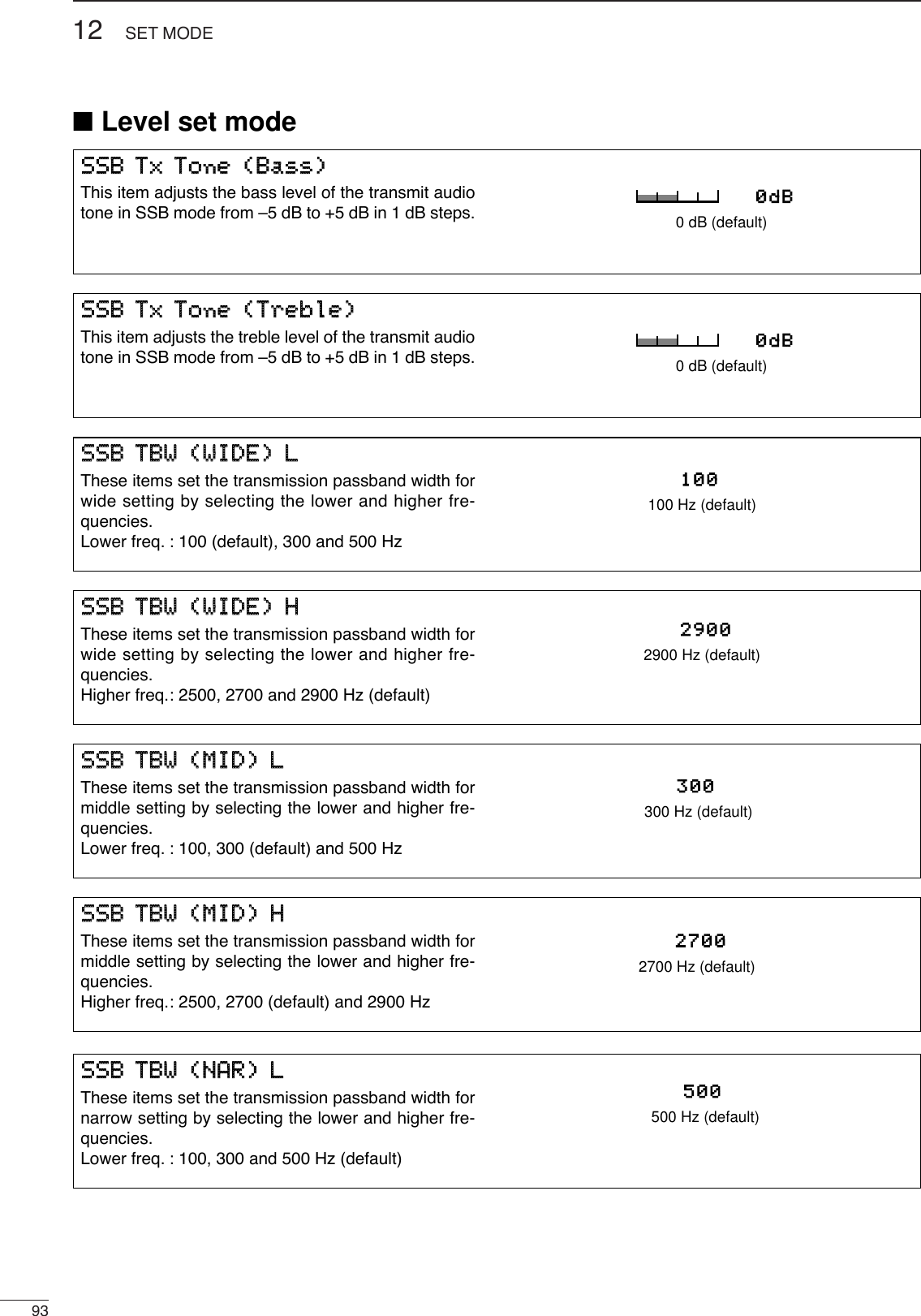
![9412SET MODE■Level set mode (continued)SSSSBB TTBBWW ((NNAARR)) HHThese items set the transmission passband width fornarrow setting by selecting the lower and higher fre-quencies.Lower freq. : 2500 (default), 2700 and 2900 Hz25002500 Hz (default)MMoonniittoorr LLeevveellThis item adjusts the transmit IF signal monitor levelfrom 0% to 100% in 1% steps.See p. 69 for details.50%50% (default)SSiiddee TToonnee LLeevveellThis item adjusts the CW side tone level from 0% to100% in 1% steps.See p. 69 for details.50%50% (default)BBeeeepp LLeevveellThis item adjusts the volume level for confirmationbeep tones from 0% to 100% in 1% steps. Whenbeep tones are turned OFF, this setting has no effect.50%50% (default)BBeeeepp LLeevveell LLiimmiittThis item allows you to set a maximum volume levelfor confirmation beep tones. Confirmation beep tonesare linked to the [AF] control until a specified volumelevel is reached — further rotation of the [AF] controlwill not increase the volume of the beep tones.OONNBeep level is limited with[AF] (default)OOFFFFBeep level is linked to [AF] SSiiddee TToonnee LLeevveell LLiimmiittThis item allows you to set a maximum volume levelfor CW side tones. CW side tones are linked to the[AF] control until a specified volume level is reached—further rotation of the [AF] control will not increasethe volume of the CW side tones.OONNCW side tone level is limitedwith [AF] (default)OOFFFFCW side tone level is linkedto [AF]](https://usermanual.wiki/ICOM-orporated/217800/User-Guide-467148-Page-99.png)
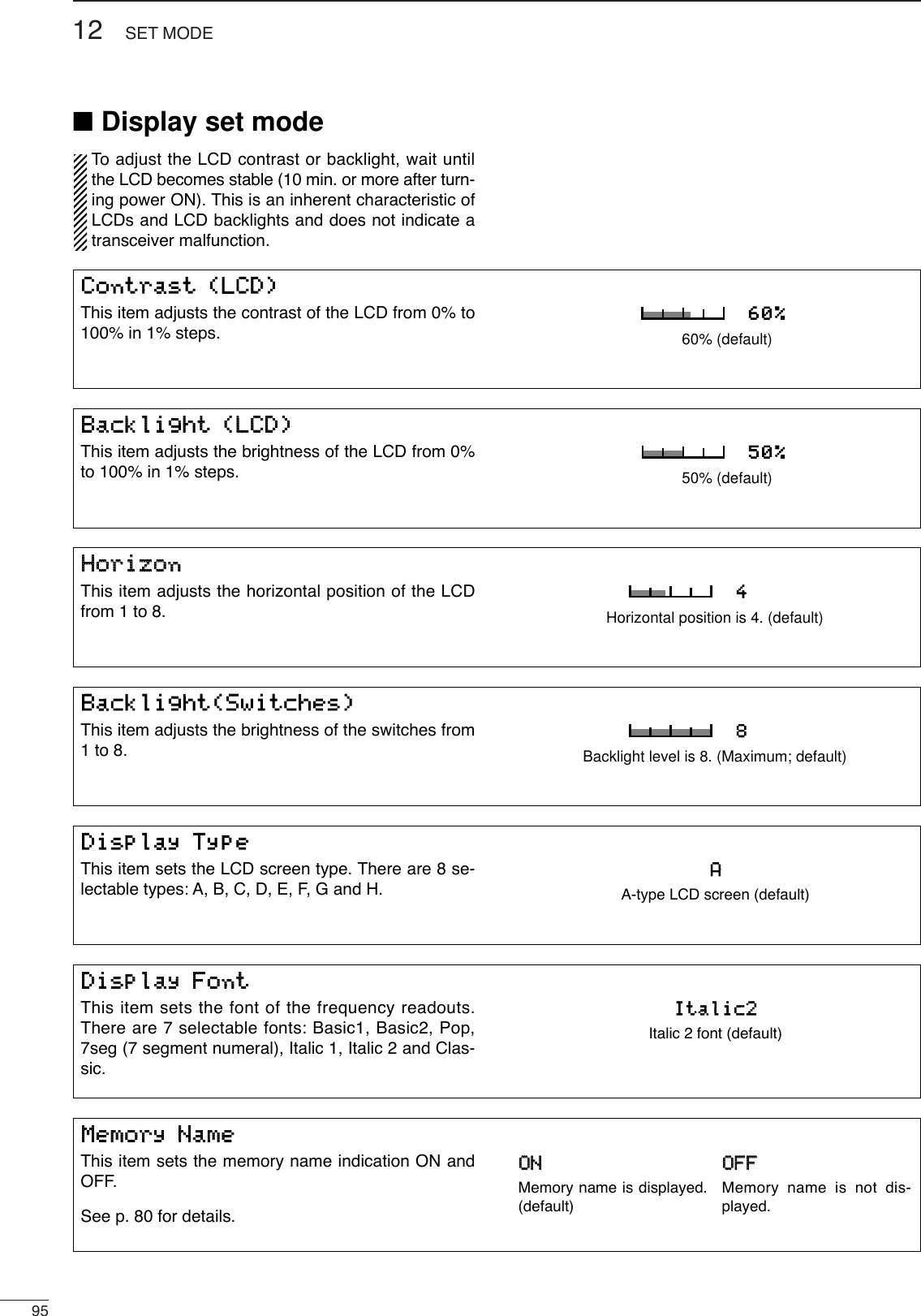
![9612SEST MODEMMyy CCaallllYour call sign, etc. can be displayed in the openingscreen when turning power ON. Up to 10 characterscan be programmed.Capital letters, numerals, some symbols (– / .) andspaces can be used.qPush [EXIT/SET] several times to close a multi-function screen, if necessary.wPush [EXIT/SET] for 1 sec. then [(F-2)DISP] mo-mentarily to select the display set mode screen.ePush [(F-2)Z] several times to select the ‘My Call’item.rPush [(F-4)EDIT] to edit.•Acursor appears and blinks.tInput the desired character by rotating the tuningdial or by pushing the band key for number input.•Push [ABC] to select capital letters.•Push [123] or [etc] to toggle numerals and symbols.•Push [(F-1)Ω] or [(F-2)≈] for cursor movement.•Push [(F-3)DEL] to delete the selected character.•Push [(F-4)SPACE] to input a space.yPush [EXIT/SET] to input the set name.•The cursor disappears.uPush [EXIT/SET] to exit the set mode screen.•Opening screen exampleja3yuaNOW CALIBRATINGDIGITAL SIGNAL PROCESSORPLEASE WAIT FOR 10sec.çåDELDEL SPACESPACE WIDEWIDEDISPLAY SET123123ABCABCCharactergroup keysSelectedcharacter Bright(LCD) 50%Horizon 4Backlight(Switches) 8DisplayType ADisplayFont Basic1MemoryName ONMyCall _A3YUAABCABCéèEDIT WIDEWIDEDISPLAY SETVOXVOXOFFOFFCOMPCOMPOFFOFFWIDEWIDEAGCAGCMIDMIDBright(LCD) 50%Horizon 4Backlight(Switches) 8DisplayType ADisplayFont Basic1MemoryName ONMyCall JA3YUA■Display set mode (continued)■DSP filter set modeTo suit your operating style, the type of DSP filtershape for SSB and CW can be selected. qPush the [EXIT/SET] several times to close amulti-function screen, if necessary.wPush the [EXIT/SET] switch for 1 sec. to enter setmode.ePush the [(F-3)DSP] switch to enter the DSP filterset mode.rPush one of [(F2)SSB-FIL] or [(F4)CW-FIL] to se-lect the desired DSP filter shape from sharp andsoft for SSB or CW mode, respectively.tPush [ENTER/SET] twice to exit the DSP filter setmode.AGCAGCMIDMIDBK-INBK-INOFFOFF1/41/4OFFOFFDSP FILTER SETSSBSSB SHARPSHARP CWCW SHARPSHARPSSB-FILSSB-FIL CW-FILCW-FILSSBSSB SOFTSOFT CWCW SOFTSOFTF-4PushF-2Push](https://usermanual.wiki/ICOM-orporated/217800/User-Guide-467148-Page-101.png)
![9712 SET MODE■Timer set modeTTiimmee ((NNooww))This item sets the current time for the built-in 24-hourclock.See p. 90 for details.1155::0000Push [(F-4)SET] to enter the time.TTiimmeerr FFuunnccttiioonnThis item sets the timer functions ON and OFF.When the power-ON timer or the power-OFF timer isused, “ON” must be selected in this item.See p. 90 for details.OONNThe timer functions can beoperated. (default)OOFFFFThe timer functions cannotbe operated.CCLLOOCCKK22 FFuunnccttiioonnThis item turns the clock 2 indication ON and OFF.The clock 2 is convenient to indicate the UTC or othercountry’s local time, etc.•ON : The clock 2 is displayed below the local timeindication.•OFF : The clock 2 does not display.OONNThe clock 2 is displayedbelow the local tiem.(default)OOFFFFThe clock 2 does not dis-play.CCLLOOCCKK22 OOffffsseettThis item sets the desired off-set time period for theclock 2 indication within –24:00 to +24:00 in 5 min.steps.•Pushing [(F-3)DEF] for 1 sec. to select the default value.++ 99::0000Rotate tuning dial to set the time.PPoowweerr--OOFFFF ppeerriiooddThis item sets the power-off period for automatic shut-down after the power-on timer has turned power ON.See p. 90 for details.6600mmiinnPush [(F-4)SET] to enter the time.PPoowweerr--OONN TTiimmeerr sseettThis item sets the power-on time.See p. 90 for details.1155::0000Push [(F-4)SET] to enter the time.](https://usermanual.wiki/ICOM-orporated/217800/User-Guide-467148-Page-102.png)
![9812SET MODE■Miscellaneous (others) set modeCCaalliibbrraattiioonn MMaarrkkeerrThis item is used for a simple frequency check of thetransceiver.See p. 107 for calibration procedure.Turn the calibration marker OFF after checking thefrequency of the transceiver.OONNCalibration marker ONOOFFFFCalibration marker OFF(default)BBeeeepp((CCoonnffiirrmmaattiioonn))Abeep sounds each time a switch is pushed to con-firm it. This function can be turned OFF for silent op-eration.The volume level can be set in level set mode. (p. 94)OONNConfirmation beep ON(default)OOFFFFConfirmation beep OFFBBeeeepp((BBaanndd EEddggee))Abeep sounds when an operating frequency entersor exits an amateur band. This functions independentof the confirmation beep setting (above).The volume level can be set in level set mode. (p. 94)OONNBand edge beep ON(default)OOFFFFBand edge beep OFFQQuuiicckk DDuuaallwwaattcchhWhen this item is set to ON, pushing [DUALWATCH]for 1 sec. sets the sub readout frequency to the mainreadout frequency and activates dualwatch operation.See p. 63 for details.OONNQuick dualwatch ON(default)OOFFFFQuick dualwatch OFFQQuuiicckk SSPPLLIITTWhen this item is set to ON, pushing [SPLIT] for 1sec. sets the sub readout frequency to the main read-out frequency and activates split operation.See p. 71 for details.OONNQuick split ON(default)OOFFFFQuick split OFFRRFF//SSQQLL CCoonnttrroollThe [RF/SQL] control can be set as the RF/squelchcontrol (default), the squelch control only (RF gain isfixed at maximum) or ‘Auto’ (RF gain control in SSB,CW and RTTY; squelch control in AM and FM).See pgs. 2, 30 for details.RRFF++SSQQLL[RF/SQL] control as RF/squelch control(default)SSQQLL[RF/SQL] control as squelch controlAAUUTTOO[RF/SQL] control as RF gain control in SSB,CW and RTTY; squelch control in AM andFM](https://usermanual.wiki/ICOM-orporated/217800/User-Guide-467148-Page-103.png)
![9912 SET MMODE■Miscellaneous (others) set mode (continued)FFMM SSPPLLIITTOOffffsseett((5500MM))This item sets the offset (difference between transmitand receive frequencies) for the quick split function.However, this setting is used for 50 MHz band FMmode only, and is used to input the repeater offset forthe 50 MHz band.The offset frequency can be set from –4 MHz to+4 MHz in 1 kHz steps.--00..550000MMHHzzMinus 0.5 MHz offset(default)++44..000000MMHHzzPlus 4.0 MHz offsetSSPPLLIITT LLOOCCKKWhen this item is ON, the tuning dial can be used toadjust the transmit frequency while pushing [XFC]even while the lock function is activated.See p. 70 for split frequency operation details.OONNSplit lock function ONOOFFFFSplit lock function OFF(default)TTuunneerr ((AAuuttoo SSttaarrtt))The internal antenna tuner has an automatic start ca-pability which starts tuning if the SWR is higher than1.5–3:1.When “OFF” is selected, the tuner remains OFF evenwhen the SWR is poor (1.5–3:1). When “ON” is se-lected, automatic tune starts even when the tuner isturned OFF.OONNAutomatic tuner start ONOOFFFFAutomatic tuner start OFF (default)TTuunneerr ((PPTTTT SSttaarrtt))Tuning of the internal antenna tuner can be startedautomatically at the moment the PTT is pushed afterthe operating frequency is changed (more than 1%from last-tuned frequency).OONNAutomatic PTT start ONOOFFFFAutomatic PTT start OFF (default)FFMM SSPPLLIITTOOffffsseett((HHFF))This item sets the offset (difference between transmitand receive frequencies) for the quick split function.However, this setting is used for HF bands in FMmode only and is used to input the repeater offset foran HF band.The offset frequency can be set from –4 MHz to+4 MHz in 1 kHz steps.--00..110000MMHHzzMinus 0.1 MHz offset(default)--44..000000MMHHzzMinus 4.0 MHz offset](https://usermanual.wiki/ICOM-orporated/217800/User-Guide-467148-Page-104.png)
![10012SET MODE■Miscellaneous (others) set mode (continued)RRTTTTYY MMaarrkk FFrreeqquueennccyyThis item selects the RTTY mark frequency. RTTYmark frequency is switched between 1275, 1615 and2125 Hz.221122552125 Hz RTTY mark frequency (default)112277551275 Hz RTTY mark frequency RRTTTTYY SShhiifftt WWiiddtthhThis item adjusts the RTTY shift width. There are 3selectable values: 170, 200 and 425 Hz.117700170 Hz RTTY shift frequency (default)442255425 Hz RTTY shiftfrequencyRRTTTTYY KKeeyyiinngg PPoollaarriittyyThis item selects the RTTY keying polarity. Normal orreverse keying polarity can be selected.When reverse polarity is selected, Mark and Spaceare reversed.- Normal : Key open/close = Mark/Space- Reverse : Key open/close = Space/MarkNNoorrmmaallNormal polarity (default)RReevveerrsseeReverse polarity[[AANNTT]] SSwwiittcchhYou can set the antenna connector selection to auto-matic, manual or non-selection (when using 1 an-tenna only).When “Auto” is selected, the antenna switch is acti-vated and the band memory memorizes the selectedantenna. See p. 87 for details.When “Manual” is selected, the antenna switch is ac-tivated and selects an antenna manually.When “OFF” is selected, the antenna switch is not ac-tivated and does not function. The [ANT1] connectoris always selected in this case.AAuuttooAntenna switch is activated and the selection is automatically memorized.(default)MMaannuuaallAntenna switch is activated.OOFFFFAntenna switch is deactivated and[ANT1] is always selected.](https://usermanual.wiki/ICOM-orporated/217800/User-Guide-467148-Page-105.png)
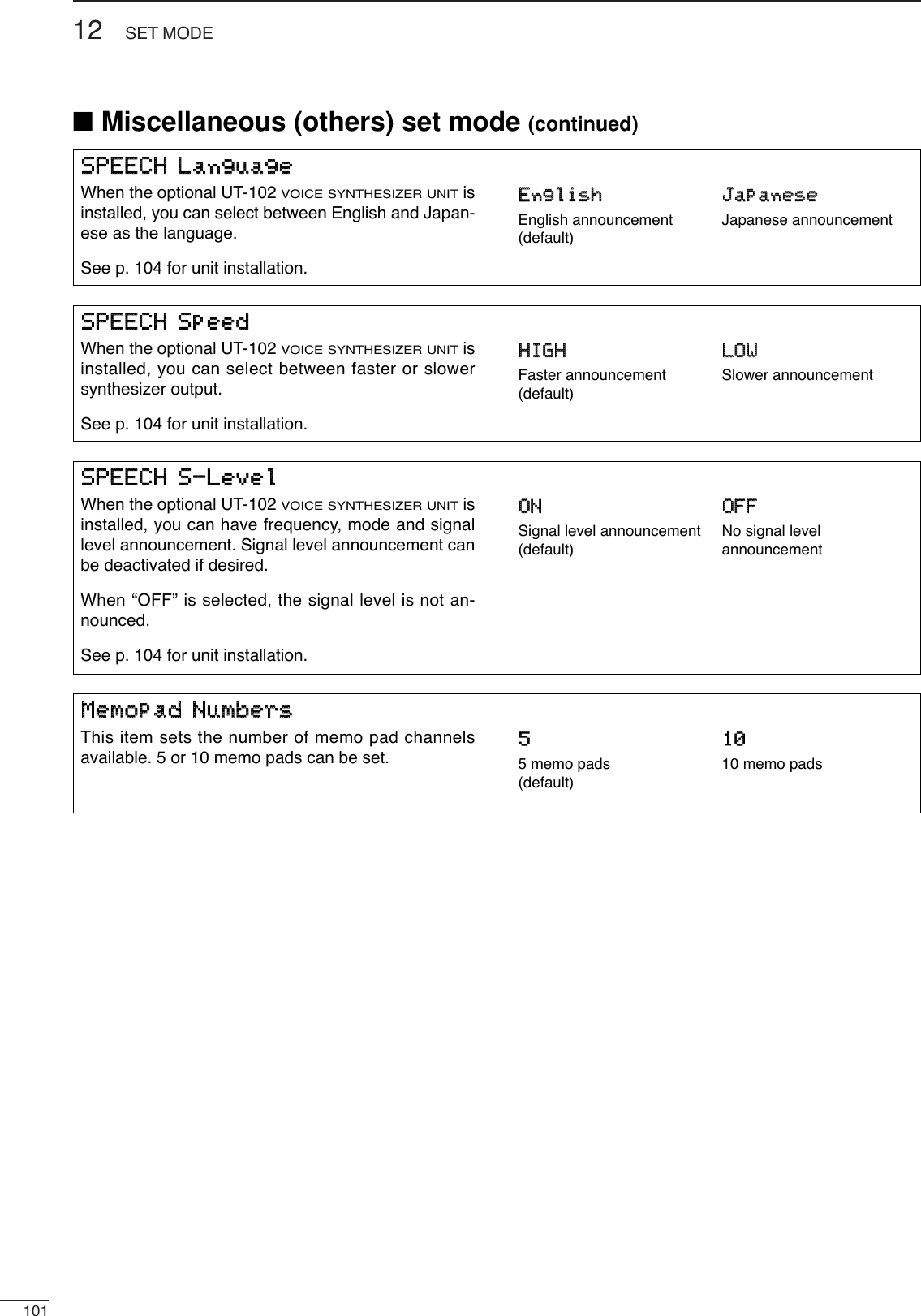
![10212SET MODE■Miscellaneous (others) set mode (continued)MMAAIINN DDIIAALL AAuuttoo TTSSThis item sets the auto tuning step function. When ro-tating the tuning dial rapidly, the tuning step automat-ically changes several times as selected. There are 2 type of auto tuning steps: HIGH (Fastest)and LOW (Faster).HHIIGGHHAuto tuning step is turned ON. Fastest tuning step during rapid rotation(default)LLOOWWAuto tuning step is turned ON. Faster tuning step during rapid rotationOOFFFFAuto tuning step is turned OFF.SSSSBB//CCWW SSyynncchhrroonnoouuss TTuunniinnggThis item selects the displayed frequency shift func-tion from ON and OFF.When this function is activated, the receiving signalcan be kept to receive even when the operating modeis changed between SSB and CW. The frequency shifting value may differ accordingto the CW pitch setting.OONNThe displayed frequencyshifts when the operatingmode is changed betweenSSB and CW.OOFFFFThe displayed frequencydoes not shift.(default)CCWW NNoorrmmaall SSiiddeeSelects the carrier point of CW mode from LSB andUSB.LLSSBBThe carrier point is set toLSB side.(default)UUSSBBThe carrier point is set toUSB side.MMIICC UUpp//DDoowwnn SSppeeeeddThis item sets the rate at which frequencies arescanned when the microphone [UP]/[DN] switchesare pushed and held. High or low can be selected.HHIIGGHHHigh speed (default, 50 tuning steps/sec.)LLOOWWLow speed (25 tuning steps/sec.)QQuuiicckk RRIITT//∂∂TTXX CClleeaarrThis item selects the RIT/∂TX frequency clearing in-struction with the [CLEAR] switch.OONNClears the RIT/∂TX fre-quency when [CLEAR] ispushed momentarily. OOFFFFClears the RIT/∂TX fre-quency when [CLEAR] ispushed for 1 sec. (default)](https://usermanual.wiki/ICOM-orporated/217800/User-Guide-467148-Page-107.png)
![10312 SSET MODE■Miscellaneous (others) set mode (continued)EExxtteerrnnaall KKeeyyppaaddThis item sets the external keypad capability andfunction. For your informationThe following diagram shows the equivalent circuit ofan external keypad and connects to the pin 3 andpin 7of the [MIC] connector (p. 18). AAuuttooPushing one of external keypadswitches, transmits the desired voicememory during a phone mode (SSB,AM or FM), or memory keyer contentsduring CW mode operation. VVOOIICCEE PPLLAAYY((TTXX))Pushing one of external keypadswitches, transmits the desired voicememory contents during a phonemode operation.KKEEYYEERR SSEENNDDPushing one of external keypadswitches, transmits the desired keyermemory contents during CW modeoperation. OOFFFFExternal keypad does not function. (default)To [MIC] connector pin e To [MIC] connector pin u 1.5kΩ±5%1.5kΩ±5%2.2kΩ±5%4.7kΩ±5%S1(T1/M1)S2(T2/M2)S3(T3/M3)S4(T4/M4)USER EXTERNAL KEYPADCCII--VV BBaauudd RRaatteeThis item sets the data transfer rate. 300, 1200, 4800,9600, 19200 bps and “Auto” are available.When “Auto” is selected, the baud rate is automati-cally set according to the connected controller or re-mote controller.AAuuttooAuto baud rate(default)119922000019200 bpsCCII--VV AAddddrreessssTo distinguish equipment, each CI-V transceiver hasits own Icom standard address in hexadecimal code.The IC-756PROIII’s address is 6Eh.When 2 or more IC-756PROIII’s are connected to anoptional CT-17 CI-VLEVEL CONVERTER, rotate the tun-ing dial to select a different address for each IC-756PROIII in the range 01h to 7Fh.66EEhhAddress of 6Eh(default)77FFhhAddress of 7FhCCII--VV TTrraannsscceeiivveeTransceive operation is possible with the IC-756PROIIIconnected to other Icom HF transceivers or receivers.When “ON” is selected, changing the frequency, op-erating mode, etc. on the IC-756PROIII automaticallychanges those of connected transceivers (or re-ceivers) and vice versa.OONNTransceive ON(default)OOFFFFTransceive OFFCCII--VV wwiitthh IICC--773311When connecting the IC-756PROIII to the IC-735 fortransceive operation, you must change the operatingfrequency data length to 4 bytes.•This item must be set to “ON” only when operating thetransceiver with the IC-735.OONN4 bytes of frequency dataOOFFFF5 bytes of frequency data(default)](https://usermanual.wiki/ICOM-orporated/217800/User-Guide-467148-Page-108.png)
![13104OPTION INSTALLATIONFollow the case and cover opening procedures shownhere when you want to install an optional unit or adjustthe internal units, etc.CAUTION: DISCONNECT the DC power cablefrom the transceiver before performing any work onthe transceiver. Otherwise, there is danger of elec-tric shock and/or equipment damage.■Opening the transceiver’s caseThe UT-102 announces the accessed readout’s fre-quency, mode, etc. (S-meter level can also be an-nounced—p. 101) in a clear, electronically-generatedvoice, in English (or Japanese).➥Push [LOCK/SPEECH] for 1 sec. to announce thefrequency, etc.qRemove the top and bottom covers as shownabove.wRemove the protective paper attached to the bot-tom of the UT-102 to expose the adhesive strip.ePlug UT-102 into J3502 on the MAIN unit asshown in the diagram at right.rAdjust the trimmer SPCH to set the speech level ifdesired. Refer to inside views on p. 108.tReturn the top and bottom covers to their originalpositions.UT-102J3502UT-102MAIN unit■UT-102 VOICE SYNTHESIZER UNITqRemove 2 screws from the left side of the trans-ceiver to remove the carrying handle as shownbelow.wRemove 7 screws from the top of the transceiverand 4 screws from the sides, then lift up the topcover.eTurn the transceiver upside down.rRemove 6 screws from the bottom of the trans-ceiver, then lift up the bottom cover.](https://usermanual.wiki/ICOM-orporated/217800/User-Guide-467148-Page-109.png)
![14105MAINTENANCESCAN■TroubleshootingThe following chart is designed to help you correctproblems which are not equipment malfunctions.If you are unable to locate the cause of a problem orsolve it through the use of this chart, contact your near-est Icom Dealer or Service Center.PROBLEM POSSIBLE CAUSE SOLUTION REF.RECEIVE POWERTRANSMITPower does not come onwhen the [POWER] switchis pushed.No sounds come out fromthe speaker.Sensitivity is too low, andonly strong signals are au-dible.Received audio is unclearor distorted.The [ANT] switch does notfunctionTransmitting is impossible.Output power is too low.No contact possible withanother station.Transmit signal is unclearor distorted.Repeater cannot be ac-cessed.Programmed scan doesnot stop.Programmed scan doesnot start.Memory scan does notstartSelect memory scan doesnot start•Power cable is improperly connected.•Fuse is blown.•Volume level is too low.•The squelch is closed.•The transceiver is in transmitting condition.•The antenna is not connected properly.•The antenna for another band is selected.•The antenna is not properly tuned.•The attenuator is activated.•Wrong operating mode is selected.•PBT function is activated.•Noise blanker is turned ON when receiving astrong signal.•Preamp is activated.•The noise reduction is activated and the [NR]control is too far clockwise.•The antenna switch has not been activated.•The operating frequency is not set to a hamband.•[RF POWER] is set too far counterclockwise•[MIC GAIN] is set too far counterclockwise•The antenna for another band is selected.•The antenna is not properly tuned.•RIT or ∂TX function is activated.•Split frequency function and/or dualwatch areactivated.•[MIC GAIN] is set too far clockwise•Split frequency function is not activated.•Programmed subaudible tone frequency iswrong.•Squelch is open.•[RF/SQL] is assigned to RF gain control andsquelch is open.•The same frequencies have been programmedin scan edge memory channels P1 and P2.•2 or more memory channels have not beenprogrammed.•2 or more memory channels have not beendesignated as select channels.•Re-connect the DC power cable correctly.•Check for the cause, then replace the fuse withthe spare one.(Fuses are installed in the DC power cable andthe internal PA unit.)•Rotate [AF] clockwise to obtain a suitable lis-tening level.•Turn [RF/SQL] to 10 o’clock position to open thesquelch.•Push [TRANSMIT] to receive or check theSEND line of an external unit, if desired.•Re-connect to the antenna connector.•Select an antenna suitable for the operating fre-quency.•Push [TUNER] for 1 sec. to manually tune theantenna.•Push [ATT] several times to select “ATT OFF.”•Select a suitable operating mode.•Push [PBT CLR] for 1 sec. to reset the function.•Push [NB] to turn the noise blanker OFF.•Push [P.AMP] once or twice to turn the functionOFF.•Set the [NR] control for maximum readability.•Set the antenna switch in set mode to “Auto” or“Manual.”•Set the frequency to a ham band.•Rotate [RF POWER] clockwise.•Set [MIC GAIN] to a suitable position.•Select an antenna suitable for the operating fre-quency.•Push [TUNER] for 1 sec. to manually tune theantenna.•Push [RIT] or [∂TX] to turn the function OFF.•Push [SPLIT] and/or [DUALWATCH] to turn thefunction OFF.•Set [MIC GAIN] to a suitable position.•Push [SPLIT] to to turn the function ON•Reset the frequency using set mode.•Set [RF/SQL] to the threshold point.•Reset [RF/SQL] control assignment and set it tothe threshold point.•Program different frequencies in scan edgememory channel P1 and P2.•Program more than 2 memory channels.•Designate more than 2 memory channels as se-lect channels for the scan.p. 16p. 106p. 1p. 2p. 1—pgs. 3,87p. 88p. 3p. 29p. 60p. 62p. 3p. 64p. 87p. 25p. 2p. 1p. 3p. 88p. 6pgs. 8,63, 70p. 1p. 8p. 52p. 2pgs. 2,30, 98p. 78p. 78pgs. 77,85](https://usermanual.wiki/ICOM-orporated/217800/User-Guide-467148-Page-110.png)
![10614MAINTENANCE■Fuse replacementIf a fuse blows or the transceiver stops functioning, tryto find the source of the problem, and replace the dam-aged fuse with a new, rated fuse.CAUTION:DISCONNECT the DC power cablefrom the transceiver when changing a fuse.The IC-756PROIII has 2 types of fuses installed fortransceiver protection.•DC power cable fuses ................................ FGB 30 A•Circuitry fuse ................................................FGB 5 ADC POWER CABLE FUSE REPLACEMENT30 A fuse■Clock backup battery replacementThe transceiver has a lithium backup battery(CR2032) inside for clock and timer functions. Theusual life of the backup battery is approximately 2years.When the backup battery is exhausted, the trans-ceiver transmits and receives normally but cannot re-tain the current time.See p. 108 for battery location.CR2032CIRCUITRY FUSE REPLACEMENTThe 13.8 V DC from the DC power cable is applied toall units in the IC-756PROIII, except for the poweramplifier, through the circuitry fuse. This fuse is in-stalled in the PA unit.qRemove the top cover as shown on p. 104.wRemove 11 screws from the PA shielding plate,then remove the plate.eReplace the circuitry fuse as shown in the diagrambelow.rReplace the PA shielding plate and top cover.Circuitry fuse (FGB 5 A)PROBLEM POSSIBLE CAUSE SOLUTION REF.DISPLAYThe displayed frequencydoes not change properly.•The dial lock function is activated.•Aset mode screen is selected.•The internal CPU has malfunctioned.•Push [LOCK/SPEECH] to turn the function OFF.•Push [EXIT/SET] several times to exit the setmode screen.•Reset the CPU.p. 64pgs. 10,92p. 21](https://usermanual.wiki/ICOM-orporated/217800/User-Guide-467148-Page-111.png)
![10714 MAINTENANCE■Tuning dial brake adjustmentThe tension of the tuning dial may be adjusted to suityour preference.The brake adjustment screw is located on the rightside of the tuning dial. See the figure at right.Turn the brake adjustment screw clockwise or coun-terclockwise to obtain a comfortable tension levelwhile turning the dial continuously and evenly in onedirection.LightHeavy■Frequency calibration (approximate)Avery accurate frequency counter is required to cali-brate the frequency of the transceiver. However, arough check may be performed by receiving radiostation WWV, or other standard frequency signals.CAUTION: Your transceiver has been thor-oughly adjusted and checked at the factory beforebeing shipped. You should not calibrate frequen-cies, except for special reasons.qPush [SSB] to select USB mode.wPush [PBT CLR] for 1 sec. to clear the PBT set-tings and make sure that the RIT/∂TX function isnot activated.eSet the frequency to the standard frequency sta-tion minus 1 kHz.•When receiving WWV (10.000.00 MHz) as a standardfrequency, set the operating frequency for9.999.00 MHz.•Other standard frequencies can also be used.rPush [EXIT/SET] several times to close a multi-function screen, if necessary.tPush [EXIT/SET] for 1 sec. to select the set modescreen.yPush [(F-5)OTHERS] to enter miscellaneous (oth-ers) set mode.uPush [(F-1)Y] several times to select the “Calibra-tion marker” item.iRotate the tuning dial clockwise to turn the calibra-tion marker ON.•Side tone may be heard.oAdjust the calibration pot on the right side panel ofthe transceiver for a zero beat with the receivedstandard signal as shown below.•Zero beat means that two signals are exactly the samefrequency, resulting in a single tone being emitted.!0 Rotate the tuning dial counterclockwise to turn thecalibration marker OFF.!1 Push [EXIT/SET] twice to exit set mode.DEFDEF WIDEWIDEéèAGCAGCMIDMIDBK-INBK-INOFFOFF1/41/4OFFOFFCalibrationCalibrationMarkerMarker ONONBeep(Confirmation)Beep(Confirmation) ONONBeep(BandBeep(BandEdge)Edge) ONONRF/SQLRF/SQLControlControl RF+SQLRF+SQLQuickQuickDualwatchDualwatch ONONQuickQuickSPRITSPRIT ONONFMFMSPLITSPLITOffset(HF)Offset(HF) -0.100MHz-0.100MHzOTHERSOTHERSSETSETSFTSFT 0FIL2FIL2USBUSBqw:ppTXTXUSBUSBo.ooo.pp14.100.0014.100.001VFOVFOBWBW 2.4k2.4kANTANT1METERMETERPoPo](https://usermanual.wiki/ICOM-orporated/217800/User-Guide-467148-Page-112.png)
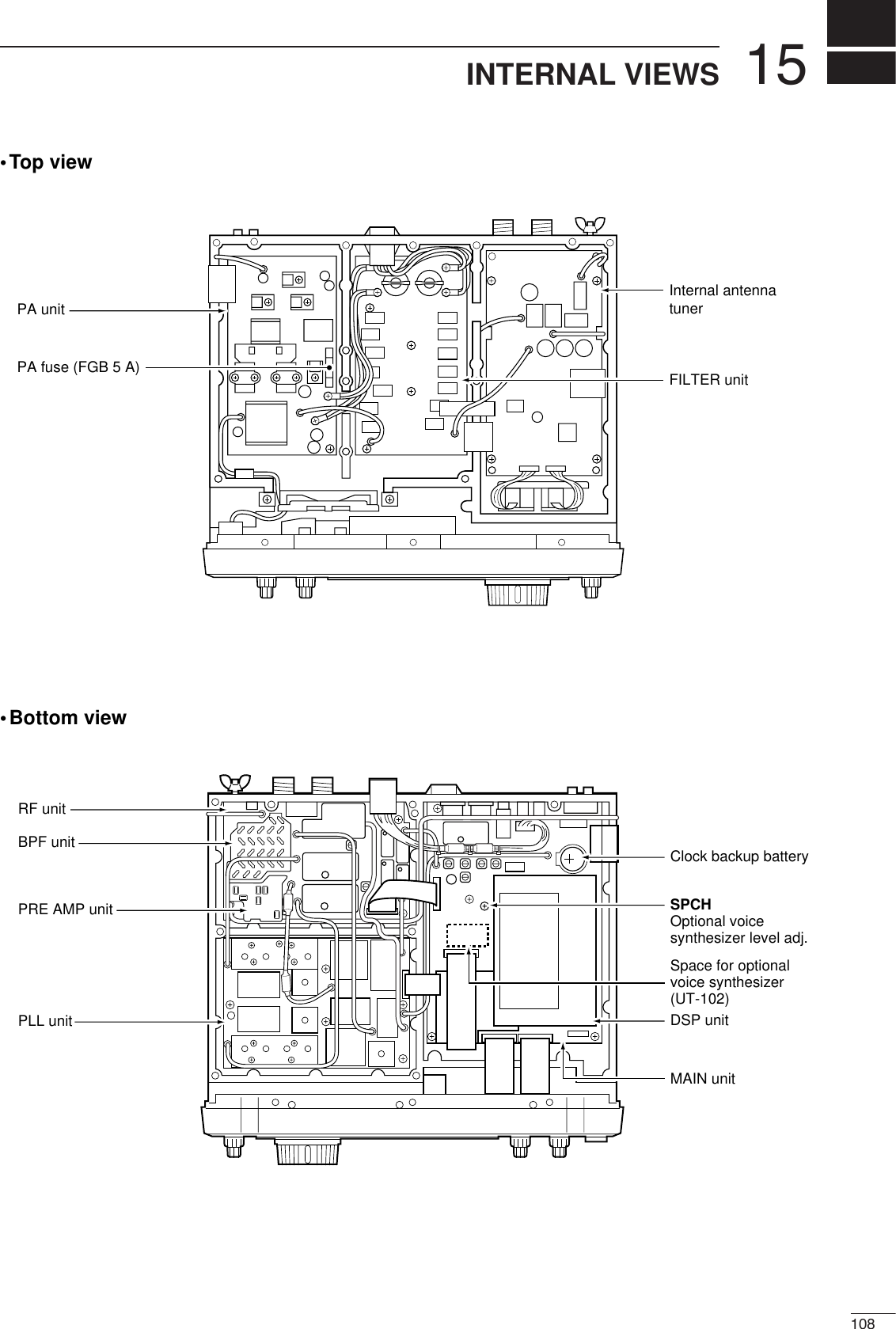
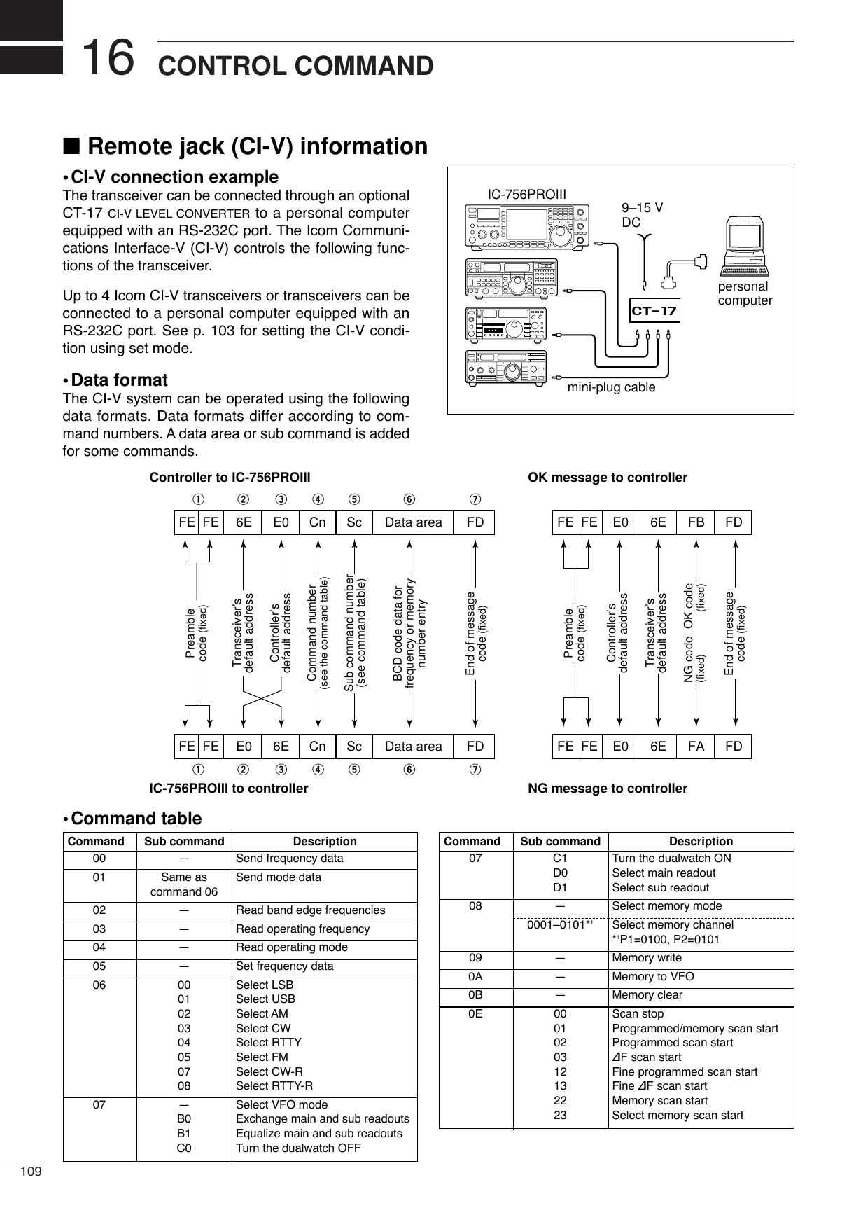
![11016CONTROL COMMAND•Command table (continued)0E A1–A7 Set ∂F scan span (A1=±5 kHz,A2=±10 kHz, A3=±20 kHz,A4=±50 kHz, A5=±100 kHz, A6=±500 kHz, A7=±1 MHz)B0 Set as non-select channelB1 Set as select channelD0 Set scan resume OFFD3 Set scan resume ON0F 00 Turn the split function OFF01 Turn the split function ON10 00 Select 10 Hz (1 Hz) tuning step01 Select 100 Hz tuning step02 Select 1 kHz tuning step03 Select 5 kHz tuning step04 Select 9 kHz tuning step05 Select 10 kHz tuning step06 Select 12.5 kHz tuning step07 Select 20 kHz tuning step08 Select 25 kHz tuning step11 00 Attenuator OFF06 Attenuator ON (6 dB)12 Attenuator ON (12 dB)18 Attenuator ON (18 dB)12 00 Select/read antenna selection01 (00=ANT1, 01=ANT2 : Add 0 or 1to turn [RX ANT] OFF or ON, re-spectively.)13 00 Announce with voice synthesizer01 (00=all data; 01=frequency and 02 S-meter level; 02=receive mode)14 01 + Level data [AF] level setting (0=max. CCW to255=max. CW)02 + Level data [RF] level setting (0=max. CCW to255=11 o’clock)03 + Level data [SQL] level setting (0=11 o’clock to255=max. CW)06 + Level data [NR] level setting (0=min. to255=max.)07 + Level data Inside [TWIN PBT] setting or IFshift setting (0=max. CCW,128=center, 255=max. CW)08 + Level data Outside [TWIN PBT] setting (0=max. CCW, 128=center,255=max. CW)09 + Level data [CW PITCH] setting (0=low pitch to255=high pitch)0A + Level data [RF POWER] setting (0=mini. to255=max.)0B + Level data [MIC GAIN] setting (0=mini. to255=max.)0C + Level data [KEY SPEED] setting (0=slow to255=fast)0D + Level data [NOTCH] setting (0=low freq. to255=high freq.)0E + Level data [COMP] setting (0=mini. to255=max.)0F + Level data [BK-IN DELAY] setting (0=shortdelay to 255=long delay)10 + Level data [BAL] level setting (0=max. CCW,128=center, 255=max. CW)12 + Level data [NB] level setting (0=mini. to255=max.)15 + Level data Monitor gain setting (0=0% to255=100%)14 16 + Level data VOX gain setting (0=0% to255=100%)17 + Level data Anti-VOX gain setting (0=0% to255=100%)18 + Level data LCD contrast setting (0=0% to255=100%)19 + Level data LCD bright setting (0=0% to255=100%)15 01 Read squelch condition02 Read S-meter level11 Read Po meter level12 Read SWR meter level13 Read ALC meter level14 Read COMP meter level16 02 Preamp (0=OFF; 1=preamp 1;2=preamp 2)12 AGC selection (1=Fast; 2=Mid;3=Slow)22 Noise blanker (0=OFF; 1=ON)40 Noise reduction (0=OFF; 1=ON)41 Auto notch (0=OFF; 1=ON)42 Repeater tone (0=OFF; 1=ON)43 Tone squelch (0=OFF; 1=ON)44Speech compressor (0=OFF; 1=ON)45 Monitor (0=OFF; 1=ON)46 VOX function (0=OFF; 1=ON)47 Break-in (0=OFF; 1=semi break-in; 2=full break-in)48 Manual notch (0=OFF; 1=ON)49 RTTY filter (0=OFF; 1=ON)4F Twin peak filter (0=OFF; 1=ON)50 Dial lock (0=OFF; 1=ON)19 00 Read the transceiver ID1A 00 Send/read memory contents (seep. 112 for details)01 Send/read band stacking registercontents (see p. 112 for details)02 Send/read memory keyer con-tents (see p. 112 for details)03 Send/read the selected filter width(0=50 Hz to 40/31=3600/2700 Hz)04 Send/read the selected AGC timeconstant (0=OFF, 1=0.1/0.3 sec. to13=6.0/8.0 sec.)0501 Send/read SSB TX Tone (Bass)level (0 =min. to 10=max.)0502 Send/read SSB TX Tone (Treble)level (0=min. to 10=max.)0503 Send/read MONITOR gain (0=min.to 255=max.)0504 Send/read CW side tone gain(0=min. to 255=max.)0505 Send/read CW side tone gain limit(0=OFF, 1=ON)0506 Send/read beep gain (0=min. to255=max.)0507 Send/read beep gain limit (0=OFF,1=ON)0508 Send/read LCD contrast (0=0% to255=100%)0509 Send/read LCD backlight (0=0% to255=100%)Command Sub command Description Command Sub command Description](https://usermanual.wiki/ICOM-orporated/217800/User-Guide-467148-Page-115.png)
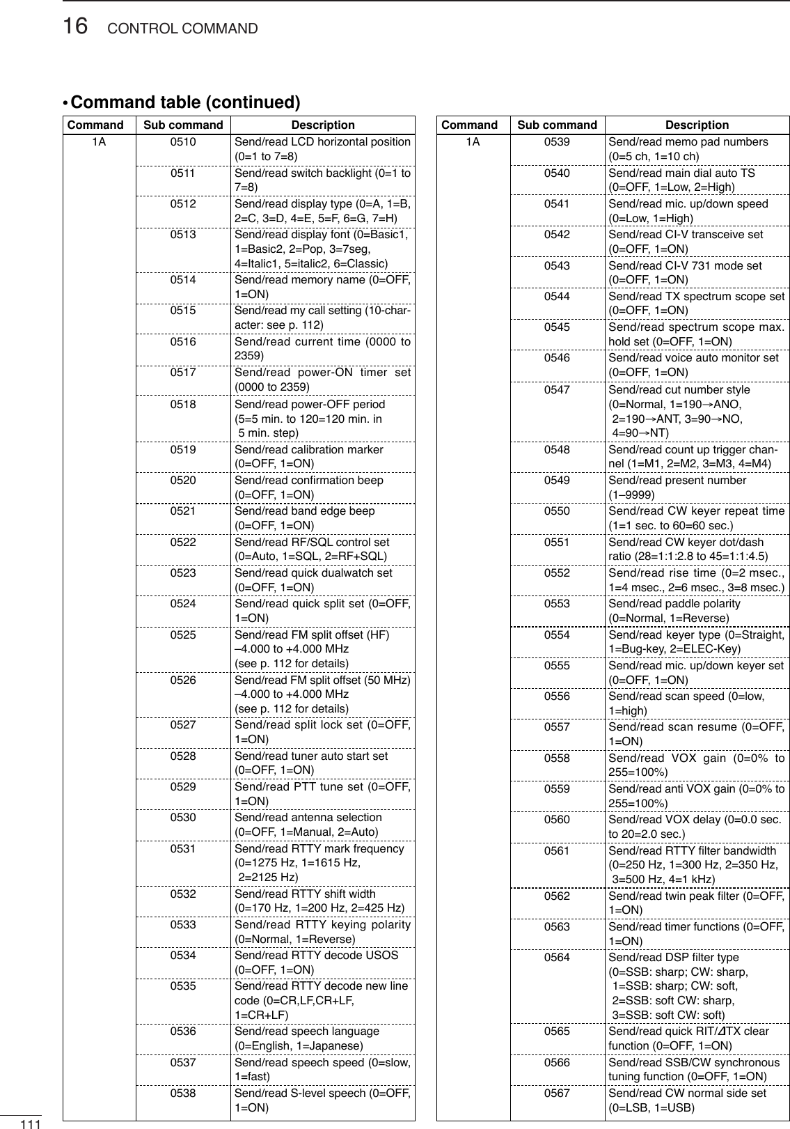
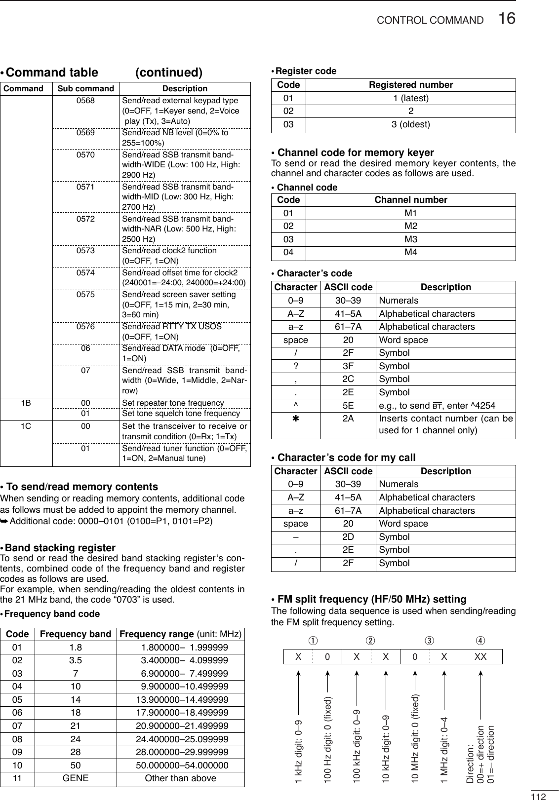
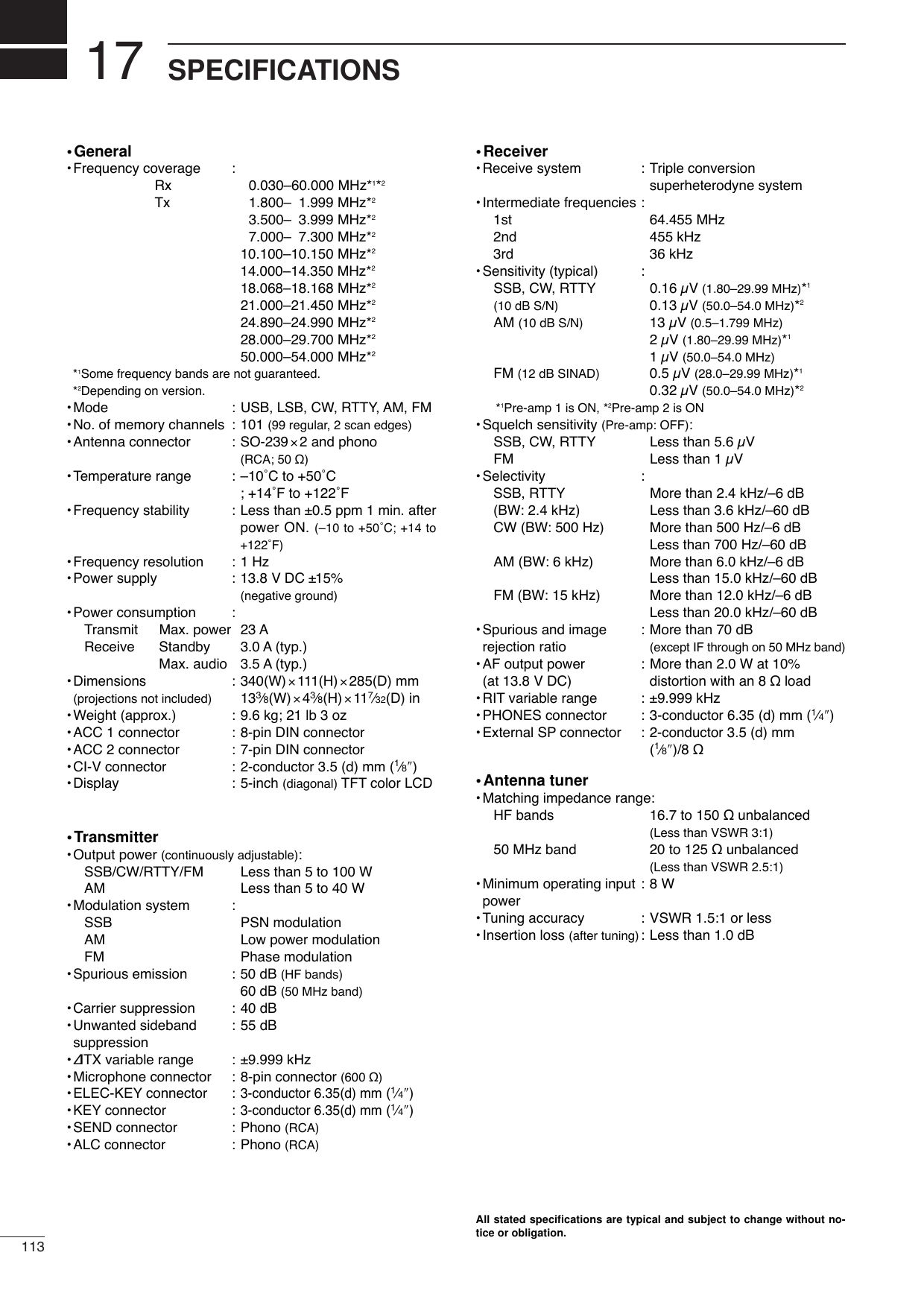
![18114OPTIONSIC-PW1 HF/50 MHz ALL BAND 1 kW LINEAR AMPLIFIERFull-duty 1 kW linear amplifier including an automatic antenna tuner. Hasautomatic tuning and band selection capability. Full break-in (QSK) oper-ation is possible. The amplifier/power supply unit and the remote controlunit are separated.AH-4 HF/50 MHz AUTOMATICANTENNA TUNERSpecially designed to tune a longwire antenna for portable or mobileHF operation. The PTT tuner startfunction provides simple operation.•Input power rating: 120 WAH-2b ANTENNA ELEMENTA2.5 m long an-tenna element formobile operationwith the AH-4.•Frequency coverage:7–54 MHz bandswith the AH-4SM-20 DESKTOP MICROPHONEUnidirectional, electret microphonefor base station operation. Includes[UP]/[DOWN] switches and a lowcut function.SP-23 EXTERNAL SPEAKER4 audio filters; headphone jack; canconnect to 2 transceivers.•Input impedance: 8 Ω•Max. input power: 5 WCT-17 CI-V LEVEL CONVERTERFor remote transceiver controlusing a personal computer. Youcan change frequencies, operatingmode, memory channels, etc.HM-36 HAND MICROPHONEHand microphone equipped with[UP]/[DOWN] switches.UT-102 VOICE SYNTHESIZER UNITAnnounces the receive frequency, modeand S-meter level in a clear, electroni-cally-generated voice, in English (orJapanese).PS-125 DC POWER SUPPLYLight weight switching regulatorsystem power supply.•Output voltage: 13.8 V DC•Max. current drain: 25 A•About DC power supplyThe use of IC-756PROIII (#33, #34, #35, #38, #40) in com-bination with the DC power supply complies with EuropeanHarmonised Standard regulations under the conditionslisted below.Conditions•In combination with PS-125•About IC-PW1 LINEAR AMPLIFIERThe IC-PW1 LINEAR AMPLIFIERdoes not comply with Euro-pean Harmonised Standard regulations. Please do not usethis equipment within European countries.](https://usermanual.wiki/ICOM-orporated/217800/User-Guide-467148-Page-119.png)