ICOM orporated 217800 HF/50 MHz All Mode Transceiver User Manual
ICOM Incorporated HF/50 MHz All Mode Transceiver Users Manual
Users Manual
INSTRUCTION MANUAL
HF/50 MHz
ALL MODE TRANSCEIVER
This device complies with Part 15 of the FCC rules. Operation is sub-
ject to the following two conditions: (1) This device may not cause
harmful interference, and (2) this device must accept any interference
received, including interference that may cause undesired operation.
i
IMPORTANT
READ THIS INSTRUCTION MANUAL
CAREFULLY before attempting to operate the
transceiver.
SAVE THIS INSTRUCTION MANUAL. This
manual contains important safety and operating in-
structions for the IC-756PROIII.
EXPLICIT DEFINITIONS
WORD DEFINITION
RRWARNING Personal injury, fire hazard or electric
shock may occur.
CAUTION Equipment damage may occur.
NOTE
If disregarded, inconvenience only. No
risk or personal injury, fire or electric
shock.
Icom, Icom Inc. and the are registered trademarks of
Icom Incorporated (Japan) in the United States, the United
Kingdom, Germany, France, Spain, Russia and/or other
countries.
FOREWORD
We understand that you have a choice of many differ-
ent radios in the market place. We would like to take a
couple of moments of your time to thank you for mak-
ing your IC-756PROIII your radio of choice, and hope
you agree with Icom’s philosophy of “technology first.”
Many hours of research and development went into
the design of your IC-756PROIII.
D
FEATURES
❍Ultimate receiver performance +30 dBm of
IP3 characteristics (HF bands only)
❍Built-in Baudot RTTY demodulator
❍Up-graded real-time spectrum scope, and
mini-scope indications
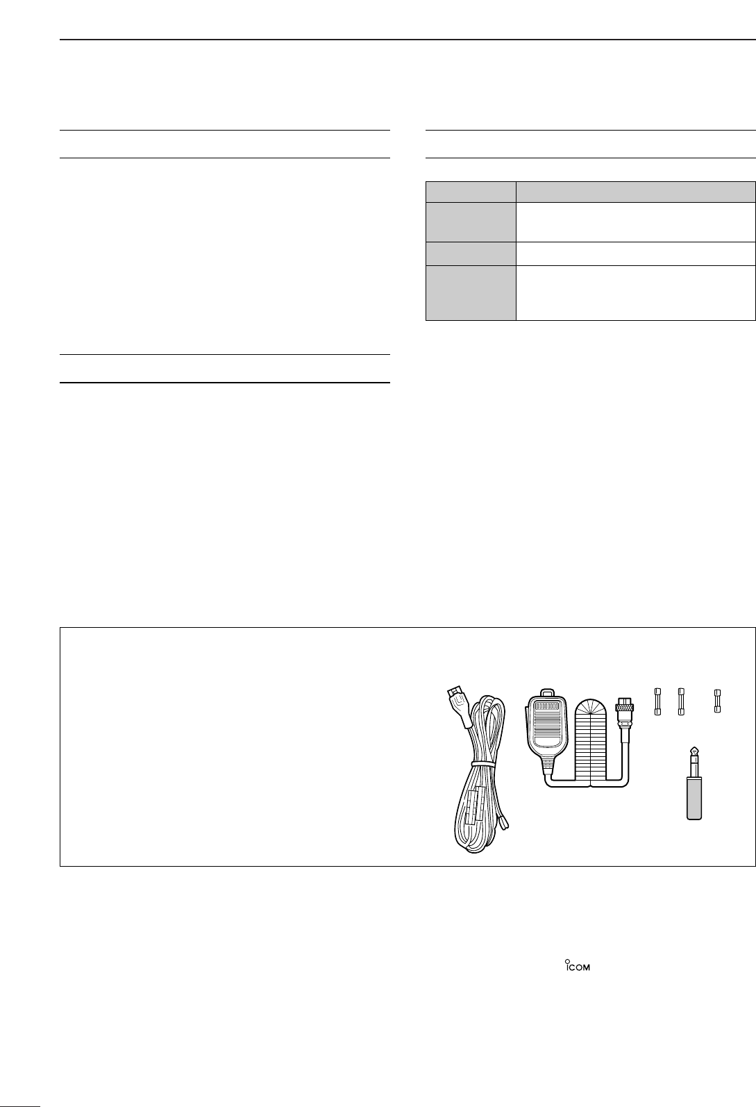
SUPPLIED ACCESSORIES
The transceiver comes with the following accessories.
Qty.
qDC power cable (OPC-025D) ............................ 1
wHand microphone (HM-36) ................................ 1
eSpare fuses (FGB 30 A) .................................... 2
rSpare fuse (FGB 5 A) ........................................ 1
tCW keyer plug (AP-330) .................................... 1
qwe
r
t

ii
RWARNING RF EXPOSURE! This device
emits Radio Frequency (RF) energy. Extreme caution
should be observed when operating this device. If you
have any questions regarding RF exposure and safety
standards please refer to the Federal Communications
Commission Office of Engineering and Technology’s
report on Evaluating Compliance with FCC Guidelines
for Human Radio Frequency Electromagnetic Fields
(OET Bulletin 65).
RWARNING HIGH VOLTAGE! NEVER at-
tach an antenna or internal antenna connector during
transmission. This may result in an electrical shock or
burn.
RWARNING! NEVER operate the transceiver
with a headset or other audio accessories at high vol-
ume levels. Hearing experts advise against continuous
high volume operation. If you experience a ringing in
your ears, reduce the volume or discontinue use.
RCAUTION! NEVER change the internal settings
of the transceiver. This result in reduced transceiver
performance and/or damage to the transceiver.
In particular, incorrect settings for transmitter circuits,
such as output power, idling current, etc., might dam-
age the expensive final devices.
The transceiver warranty does not cover any problems
caused by unauthorized internal adjustment.
RNEVER apply AC to the [DC13.8V] jack on the
transceiver rear panel. This could cause a fire or ruin
the transceiver.
RNEVER apply more than 16 V DC, such as a 24 V
battery, to the [DC13.8V] jack on the transceiver rear
panel. This could cause a fire or ruin the transceiver.
RNEVER let metal, wire or other objects touch any
internal part or connectors on the rear panel of the
transceiver. This may result in an electric shock.
RNEVER expose the transceiver to rain, snow or
any liquids.
RNEVER installing the transceiver in a place with-
out adequate ventilation. Heat dissipation may be af-
fected, and the transceiver may be damaged.
RNEVER operate or touch the transceiver with wet
hands. This may result in an electric shock or damage
the transceiver.
AVOID using or placing the transceiver in areas with
temperatures below –10°C (+14°F) or above +50°C
(+122°F). Be aware that temperatures on a vehicle’s
dashboard can exceed 80°C (+176°F), resulting in per-
manent damage to the transceiver if left there for ex-
tended periods.
AVOID placing the transceiver in excessively dusty en-
vironments or in direct sunlight.
AVOID placing the transceiver against walls or putting
anything on top of the transceiver. This will obstruct
heat dissipation.
Place unit in a secure place to avoid inadvertent use
by children.
During mobile operation, DO NOT operate the trans-
ceiver without running the vehicle’s engine. When
transceiver power is ON and your vehicle’s engine is
OFF, the vehicle’s battery will soon become ex-
hausted.
Make sure the transceiver power is OFF before start-
ing the vehicle. This will avoid possible damage to the
transceiver by ignition voltage spikes.
During maritime mobile operation, keep the transceiver
and microphone as far away as possible from the mag-
netic navigation compass to prevent erroneous indica-
tions.
BE CAREFUL! The heatsink will become hot when op-
erating the transceiver continuously for long periods.
BE CAREFUL! If a linear amplifier is connected, set
the transceiver’s RF output power to less than the lin-
ear amplifier’s maximum input level, otherwise, the lin-
ear amplifier will be damaged.
The LCD display may have cosmetic imperfections
that appear as small or dark spots. This is not a mal-
function or defect, but a normal characteristic of LCD
displays.
Use Icom microphones only (supplied or optional).
Other manufacturer’s microphones have different pin
assignments, and connection to the IC-756PROIII may
damage the transceiver.
For U.S.A. only
CAUTION: Changes or modifications to this device,
not expressly approved by Icom Inc., could void your
authority to operate this device under FCC regulations.
PRECAUTIONS

iii
TABLE OF CONTENTS
IMPORTANT .................................................................. i
EXPLICIT DEFINITIONS ............................................... i
FOREWORD ................................................................. i
SUPPLIED ACCESSORIES .......................................... i
PRECAUTIONS ............................................................ ii
TABLE OF CONTENTS .............................................. iii
1PANEL DESCRIPTION ..................................... 1–12
■Front panel ....................................................... 1
■LCD display ..................................................... 9
■Screen menu arrangement ............................ 10
■Rear panel ...................................................... 11
■Microphone (HM-36) ...................................... 12
2INSTALLATION AND CONNECTIONS .......... 13–20
■Unpacking ...................................................... 13
■Selecting a location ........................................ 13
■Grounding ...................................................... 13
■Antenna connection ....................................... 13
■Required connections .................................... 14
■Advanced connections ................................... 15
■Power supply connections ............................. 16
■Linear amplifier connections .......................... 17
■External antenna tuner
connections .................................................... 18
■Transverter jack information .......................... 18
■Microphone connector information ................ 18
■FSK and AFSK (SSTV)
connections .................................................... 19
■Accessory connector information ................... 20
3BASIC OPERATION ....................................... 21–32
■When first applying power
(CPU resetting) .............................................. 21
■Initial settings ................................................. 21
■VFO description ............................................. 22
■Selecting VFO/memory mode ........................ 23
■Main/Sub band selection ............................... 23
■Selecting an operating band .......................... 24
■Frequency setting .......................................... 25
■Operating mode selection .............................. 29
■Volume setting ............................................... 29
■Squelch and receive (RF) sensitivity ............. 30
■Meter function ................................................ 31
■SWR reading ................................................. 31
■Basic transmit operation ................................ 32
4RECEIVE AND TRANSMIT ............................ 33–54
■Operating SSB ............................................... 33
■Operating CW ................................................ 35
■Electronic CW keyer ...................................... 38
■Operating RTTY (FSK) .................................. 44
■Operating AM ................................................. 50
■Operating FM ................................................. 51
■Repeater operation ........................................ 52
■Tone squelch operation .................................. 53
■Data mode (SSTV/PSK31) operation ............ 54
5FUNCTION FOR RECEIVE ............................ 55–64
■Spectrum scope screen ................................. 55
■Preamp .......................................................... 57
■Attenuator ...................................................... 57
■RIT function .................................................... 58
■AGC function .................................................. 59
■Twin PBT operation ........................................ 60
■IF filter selection ............................................. 61
■DSP filter shape.............................................. 62
■Noise blanker ................................................. 62
■Dualwatch operation ...................................... 63
■Notch function ................................................ 64
■Noise reduction .............................................. 64
■Dial lock function ............................................ 64
6FUNCTION FOR TRANSMIT ......................... 65–71
■VOX function .................................................. 65
■Break-in function ............................................ 66
■Transmit filter width setting (SSB only) .......... 67
■Speech compressor ....................................... 67
■∂TX function .................................................. 68
■Monitor function ............................................. 69
■Split frequency operation ............................... 70
■Quick split function ......................................... 71
7VOICE RECODER FUNCTIONS .................... 72–75
■Digital voice recorder ..................................... 72
8MEMORY OPERATION .................................. 76–75
■Memory channels .......................................... 76
■Memory channel selection ............................. 76
■Memory channel screen ................................ 77
■Memory channel programming ...................... 78
■Frequency transferring ................................... 79
■Memory names .............................................. 80
■Memory clearing ............................................ 80
■Memo pads .................................................... 81
9SCANS ........................................................... 82–86
■Scan types ..................................................... 82
■Preparation .................................................... 82
■Programmed scan operation ......................... 83
■∂F scan operation ......................................... 83
■Fine programmed scan/
fine ∂F scan ................................................... 84
■Memory scan operation ................................. 84
■Select memory scan operation ...................... 85
■Setting select memory channels .................... 85
■Scan set mode ............................................... 86
■Tone scan ....................................................... 86
10 ANTENNA TUNER FUNCTIONS ................... 87–89
■Automatic antenna selection .......................... 87
■Antenna tuner operation ................................ 88
■Optional external tuner operation .................. 89

iv
TABLE OF CONTENTS
1
2
3
4
5
6
7
8
9
10
11
12
13
14
15
16
17
18
19
11 CLOCK AND TIMERS .................................... 90–91
■Setting the current time .................................. 90
■Timer function activity ..................................... 90
■Setting power-on time .................................... 91
■Setting power-off period ................................. 91
■Timer operation .............................................. 91
12 SET MODE ................................................... 92–103
■Set mode description ..................................... 92
■Level set mode .............................................. 93
■Display set mode ........................................... 95
■DSP filter set mode......................................... 96
■Timer set mode .............................................. 97
■Miscellaneous (others) set mode ................... 98
13 OPTION INSTALLATION .................................... 104
■Opening the transceiver’s case ................... 104
■UT-102
VOICE SYNTHESIZER UNIT
.................. 104
14 MAINTENANCE ......................................... 105–107
■Troubleshooting ........................................... 105
■Fuse replacement ........................................ 106
■Clock backup battery
replacement ................................................. 106
■Tuning dial brake adjustment ....................... 107
■Frequency calibration
(approximate)................................................ 107
15 INTERNAL VIEWS .............................................. 108
16 CONTROL COMMAND ............................... 109–112
■Remote jack (CI-V) information ................... 109
17 SPECIFICATIONS ............................................... 113
18 OPTIONS ............................................................. 114
19 ABOUT CE ........................................................... 115
1
1
PANEL DESCRIPTION
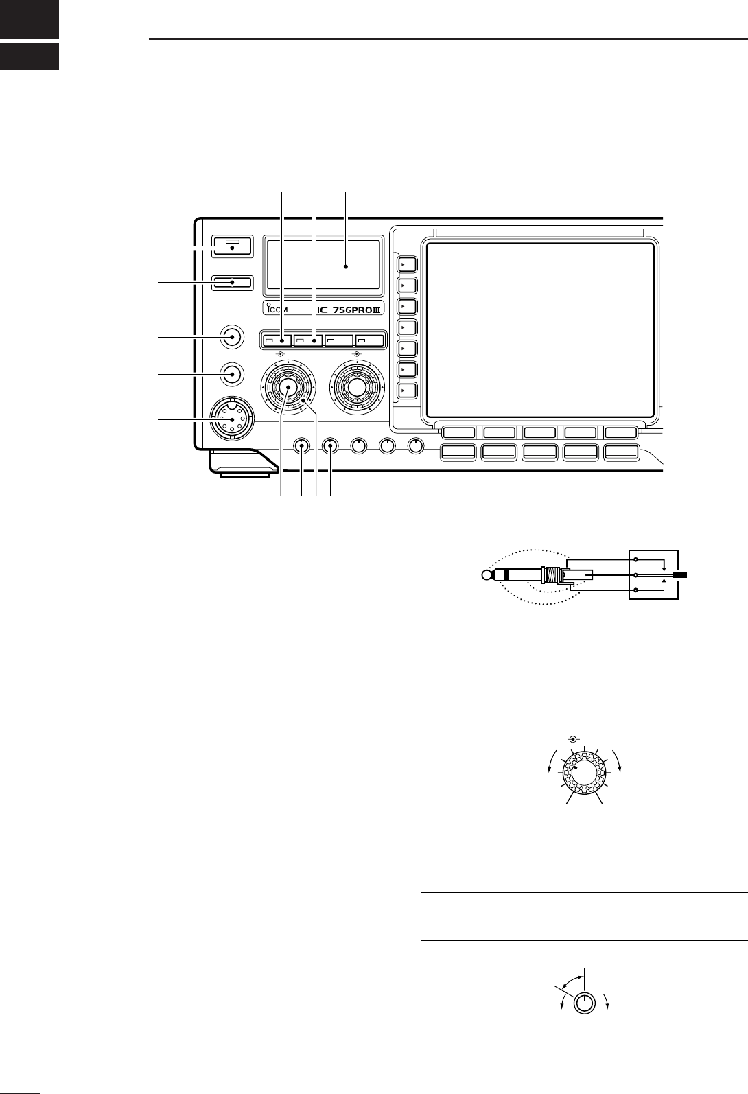
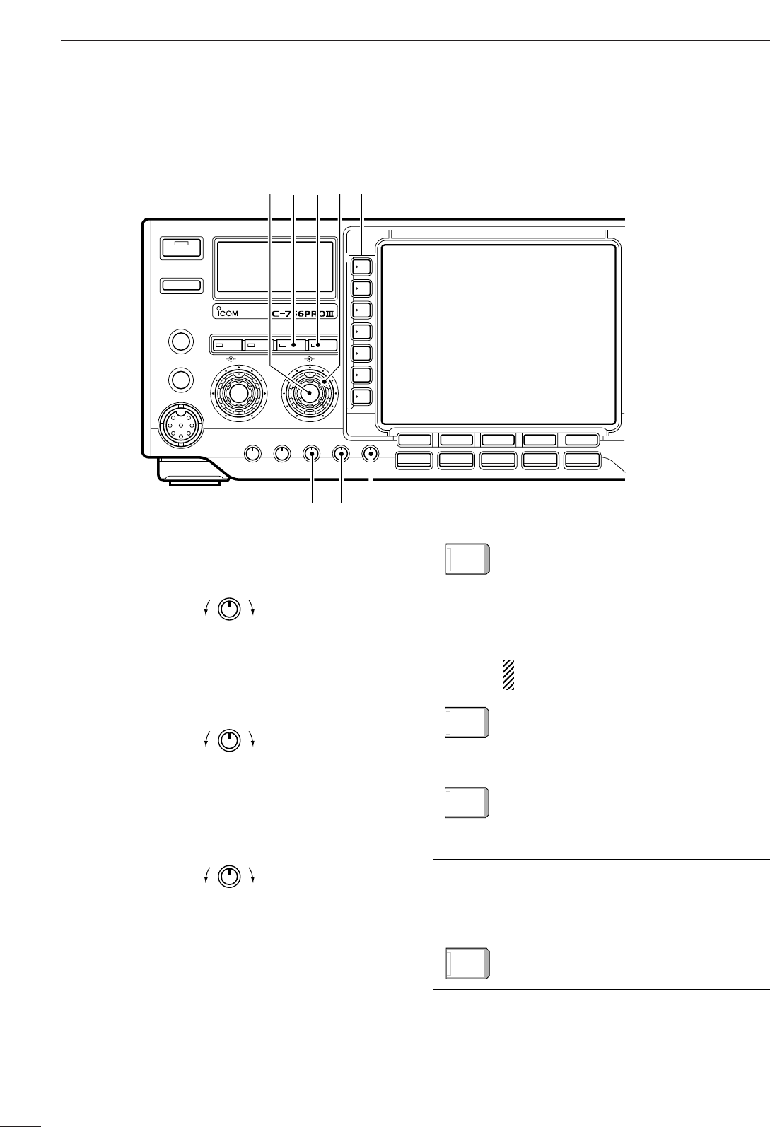
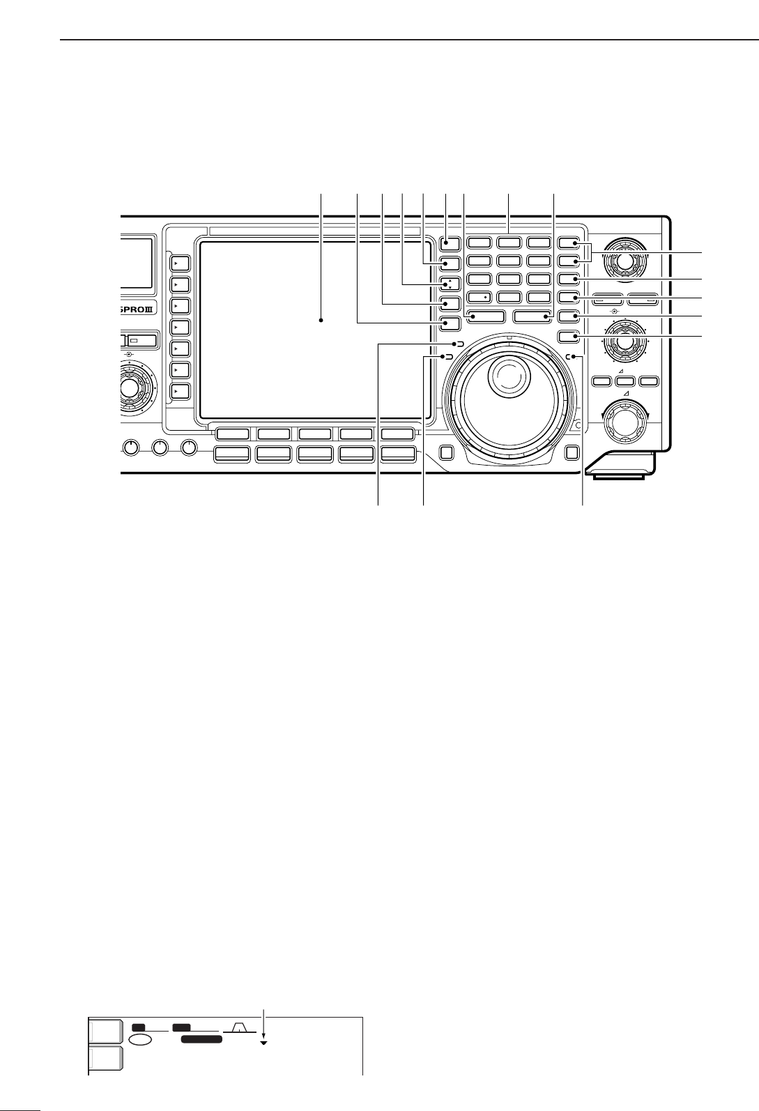
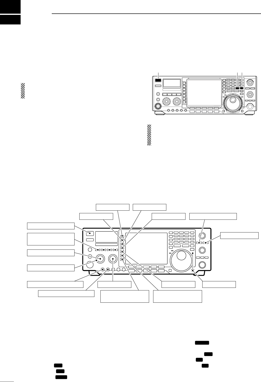
■Front panel
qPOWER SWITCH [POWER/TIMER]
➥While transceiver’s power is OFF:
Push to turn power ON.
•Turn the optional DC power supply ON in advance.
•A/D converter calibration of the DSP unit starts and it
takes approx. 10 sec.
➥While transceiver’s power is ON:
❍Push momentarily to toggle the timer function
ON and OFF. (p. 91)
•The [TIMER] indicator in this switch lights while the
timer function is ON.
❍Push for 1 sec. to turn power OFF.
wTRANSMIT SWITCH [TRANSMIT]
Selects transmitting or receiving.
•The [TX] indicator lights red while transmitting and the
[RX] indicator lights green when the squelch is open.
eHEADPHONE JACK [PHONES]
Accepts headphones.
•Output power: 5 mW with an 8 Ωload.
•When headphones are connected, the internal speaker
or connected external speaker does not function.
rELECTRONIC KEYER JACK [ELEC-KEY]
Accepts a paddle to activate the internal electronic
keyer for CW operation. (p. 38)
•Selection between the internal electronic keyer, bug-key
and straight key operation can be made in keyer set
mode. (p. 43)
•A straight key jack is separately available on the rear
panel. See [KEY] on p. 11.
•Keyer polarity (dot and dash) can be reversed in keyer
set mode. (p. 43)
•4-channel memory keyer is available for your conve-
nience. (p. 40)
tMICROPHONE CONNECTOR [MIC]
Accepts the supplied or optional microphone.
•See p. 114 for appropriate microphones.
•See p. 18 for microphone connector information.
yAF CONTROL [AF] (inner control)
Varies the audio output level from the speaker.
uMIC GAIN CONTROL [MIC GAIN]
Adjusts microphone input gain.
•The transmit audio tone in SSB mode can be adjusted in
set mode. (p. 93)
✔
How to set the microphone gain.
Set the [MIC] control so that the ALC meter sometimes
swings during normal voice transmission in SSB mode.
MIC GAIN
Recommended level for
an Icom microphone
IncreasesDecreases
AF RF/SQL
No audio output Max. audio output
Decreases Increases
(dot)
(com)
(dash)
TIMER
POWER
TRANSMIT
PHONES
ELEC-KEY
MIC
TUNER MONITOR NB NR
AF BAL NRRF/SQL
MIC GAIN RF POWER COMP BK-IN DELAY KEY SPEED
F-1 F-2 F-3 F-4 F-5
HF/50MHz TRANSCEIVER
SSB
CW/RTTY
AM/FM FILTER EXIT/SET
q
w
e
r
t
!0!1!2
yiou
2
1
PANEL DESCRIPTION
1
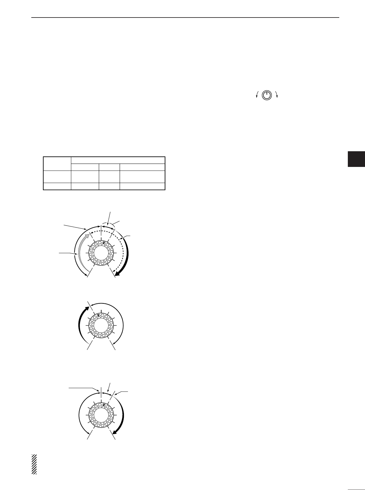
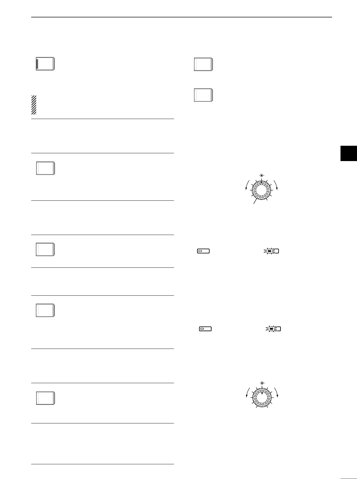
iRF GAIN CONTROL/SQUELCH CONTROL
[RF/SQL] (outer control)
Adjusts the RF gain and squelch threshold level.
The squelch removes noise output from the
speaker (closed condition) when no signal is re-
ceived.
•The squelch is particularly effective for FM. It is also
available for other modes.
•12 to 1 o’clock position is recommended for any setting
of the [RF/SQL] control.
•The control can be set as ‘Auto’ (RF gain control in SSB,
CW and RTTY; squelch control in AM and FM) or
squelch control (RF gain is fixed at maximum) in set
mode as follows. (p. 98)
•When setting as RF gain/squelch control
•When functioning as RF gain control
(Squelch is fixed open; SSB, CW, RTTY only)
•When functioning as squelch control
(RF gain is fixed at maximum.)
While rotating the RF gain control, noise may be
heard. This comes from the DSP unit and does not
indicate an equipment malfunction.
oRF POWER CONTROL [RF POWER]
Continuously varies the RF output power from min-
imum (5 W*) to maximum (100 W*).
*AM mode: 5 W to 40 W
!0 S/RF METER (p. 31)
Shows the signal strength while receiving. Shows
the relative output power, SWR, ALC or compres-
sion levels while transmitting.
!1 MONITOR SWITCH [MONITOR] (p. 69)
Monitors your transmitted IF signal.
•The CW sidetone functions regardless of the [MONI-
TOR] switch setting in CW mode.
•The [MONITOR] indicator in this switch lights green
when the function is activated.
!2 ANTENNA TUNER SWITCH [TUNER] (p. 88)
➥Turns the internal antenna tuner ON and OFF
(bypass) when pushed momentarily.
➥Tunes the antenna manually when pushed for 1
sec.
•The [TUNER] indicator in this switch lights red when
the function is activated or blinks during manual tun-
ing.
•When the tuner cannot tune the antenna, the tuning
circuit is bypassed automatically after 20 sec.
RF POWER
IncreasesDecreases
Squelch is
open.
S-meter
squelch
S-meter squelch
threshold
Noise squelch
threshold
(FM mode)
Shallow Deep
Noise squelch (FM mode)
Minimum RF gain
Adjustable
range
Maximum
RF gain
Recommended level
RF gain
adjustable
range
Maximum
RF gain
S-meter
squelch
Noise squelch (FM mode)
Squelch is
open.
MODE
SSB, CW
RTTY
AM, FM
AUTO
RF GAIN
SQL
SQL
SET MODE SETTING
SQL
SQL
RF GAIN + SQL
RF GAIN + SQL
RF GAIN + SQL
3
1PANEL DESCRIPTION
■Front panel (continued)
!3 COMPRESSION LEVEL CONTROL [COMP]
(p. 67)
Adjusts the speech compression level in SSB.
!4 SEMI BREAK-IN DELAY CONTROL
[BK-IN DELAY]
Adjusts the transmit-to-receive switching delay time
for CW semi break-in operation.
!5 ELECTRONIC CW KEYER SPEED CONTROL
[KEY SPEED] (p. 35)
Adjusts the internal electronic CW keyer’s speed.
•6 wpm (min.) to 60 wpm (max.) can be set.
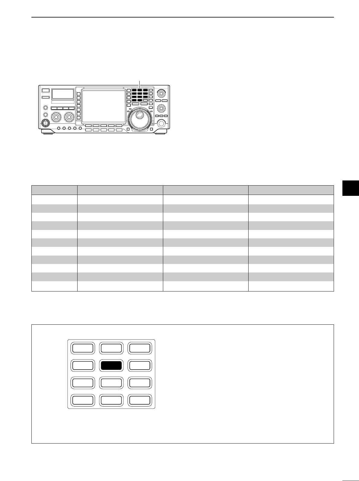
!6 MULTI-FUNCTION SWITCHES
Push to select the functions indicated in the LCD
display to the right of these switches.
•Functions vary depending on the operating condition.
➥Selects the antenna connector between
ANT1 and ANT2 when pushed. (p. 87)
➥Turns the [RX ANT] (receive antenna) ON
and OFF when pushed for 1 sec.
•When the receive antenna is activated, the
antenna which is connected to the [ANT1] or
[ANT2] is used for transmission only.
When a transverter is in use, this [ANT]
does not function and ‘XVERT’ appears.
➥Selects RF power (Po), SWR, ALC or
COMP metering during transmit. (p. 31)
➥Switches the multi-function digital meter
ON and OFF when pushed for 1 sec.
➥Selects one of 2 receive RF preamps or
bypasses them. (p. 57)
•“P. AMP1” activates 10 dB preamp.
•“P. AMP2” activates 16 dB high-gain preamp.
✔
What is the preamp?
The preamp amplifies received signals in the front end cir-
cuit to improve the S/N ratio and sensitivity. Select “P. AMP1”
or “P. AMP2” when receiving weak signals.
➥Selects 6 dB, 12 dB or 18 dB attenuator,
or bypasses them.
✔
What is the attenuator?
The attenuator prevents a desired signal from distorting
when very strong signals are near the desired frequency, or
when very strong electric fields, such as from a broadcast-
ing station, are near your location.
ATT
ATT
OFF
OFF
P.AMP
P.AMP
OFF
OFF
METER
METER
Po
Po
ANT
ANT
1
Slow Fast
KEY SPEED
BK-IN DELAY
Short delay for
high speed keying
(2 dot)
Long delay for
slow speed keying
(13 dot)
COMP
Compression
level decreases Compression
level increases
TIMER
POWER
TRANSMIT
PHONES
ELEC-KEY
MIC
TUNER MONITOR NB NR
AF BAL NRRF/SQL
MIC GAIN RF POWER COMP BK-IN DELAY KEY SPEED
F-1 F-2 F-3 F-4 F-5
HF/50MHz TRANSCEIVER
SSB
CW/RTTY
AM/FM FILTER EXIT/SET
!5!4!3
!6!7!8@0 !9
4
1
PANEL DESCRIPTION
1
➥Activates or selects fast, middle or slow
AGC time constant when pushed. (p. 59)
•“FAST” is only available for FM mode.
➥Enters the AGC set mode when pushed
for 1 sec. (p. 59)
AGC time constant can be set between 0.1 to
8.0 sec. (depends on mode), or turned OFF. While
“OFF” is selected, the S-meter does not function.
✔
What is the AGC?
The AGC controls receiver gain to produce a constant audio
output level, even when the received signal strength is varied
by fading, etc. Select “FAST” for tuning and select “MID” or
“SLOW” depending on the receiving condition.
➥Turns the VOX function ON and OFF
when pushed in a phone mode (SSB, AM
or FM mode). (p. 65)
➥Enters the VOX set mode when pushed
for 1 sec. in a phone mode. (p. 65)
✔
What is the VOX function?
The VOX function (voice operated transmission) starts trans-
mission without pushing the transmit switch or PTT switch
when you speak into the microphone; then, automatically re-
turns to receive when you stop speaking.
➥Selects semi break-in, full break-in oper-
ation, or turns the break-in operation
OFF when pushed in CW mode. (p. 66)
✔
What is the break-in function?
The break-in function switches transmit and receive with CW
keying. Full break-in (QSK) can monitor the receive signal
during keying.
➥Turns the RTTY filter ON and OFF in
RTTY mode. (p. 45)
•When the RTTY filter is turned ON, [TWIN
PBT] functions as the IF shift control.
➥Enters the RTTY filter set mode when
pushed for 1 sec. in RTTY mode. (p. 45)
✔
What is the IF shift?
The IF shift function electronically changes the center of the
IF (Intermediate Frequency) passband frequency to reject in-
terference. Only the inner control of [TWIN PBT] can be used
for the IF shift control.
➥Turns the speech compressor ON and
OFF in SSB mode. (p. 67)
➥Switches the narrow, middle or wide
transmit filter when pushed for 1 sec.
✔
What is the speech compressor?
The speech compressor compresses the transmitter audio
input to increase the average audio output level. Therefore,
talk power is increased. This function is effective for long dis-
tance communication or when propagation conditions are
poor.
➥Turns the 1⁄4function ON and OFF in
SSB data, CW and RTTY modes. (p. 27)
•1⁄4function sets dial rotation to 1⁄4of normal
for fine tuning.
➥Switches the tone encoder, tone squelch
function and no tone operation when
pushed in FM mode. (pgs. 52, 53
➥Enters the tone set mode when pushed
for 1 sec. in FM mode. (pgs. 52, 53)
!7 NOISE REDUCTION LEVEL CONTROL [NR]
(outer control; p. 64)
Adjusts the noise reduction level when the noise re-
duction is in use. Set for maximum readability.
•To activate this control, turn the noise reduction ON in
advance (!8).
!8 NOISE REDUCTION SWITCH [NR] (p. 64)
Push to switch the noise reduction ON and OFF.
•The [NR] indicator in this switch lights green when the
function is activated.
!9 NOISE BLANKER SWITCH [NB] (p. 62)
➥Switches the noise blanker ON and OFF when
pushed. The noise blanker reduces pulse-type
noise such as that generated by automobile igni-
tion systems. This function cannot be used for
FM, or non-pulse-type noise.
•The [NB] indicator in this switch lights green when the
function is activated.
➥Enters the noise blanker level set mode when
pushed for 1 sec.
@0 BALANCE CONTROL [BAL] (inner control; p. 63)
Adjusts the audio output balance between main and
sub readout frequencies while in dualwatch.
BAL NR
Increases main
readout gain Increases sub
readout gain
Noise blanker OFF Noise blanker ON
NB NB
Noise reduction OFF Noise reduction ON
NR NR
BAL NR
Decreases
OFF
Increases
TONE
TONE
OFF
OFF
1/4
1/4
OFF
OFF
COMP
COMP
OFF
OFF
WIDE
WIDE
RTTY
RTTY
FIL
FIL
OFF
OFF
BK-IN
BK-IN
OFF
OFF
VOX
VOX
OFF
OFF
AGC
AGC
MID
MID
5
1PANEL DESCRIPTION
■Front panel (continued)
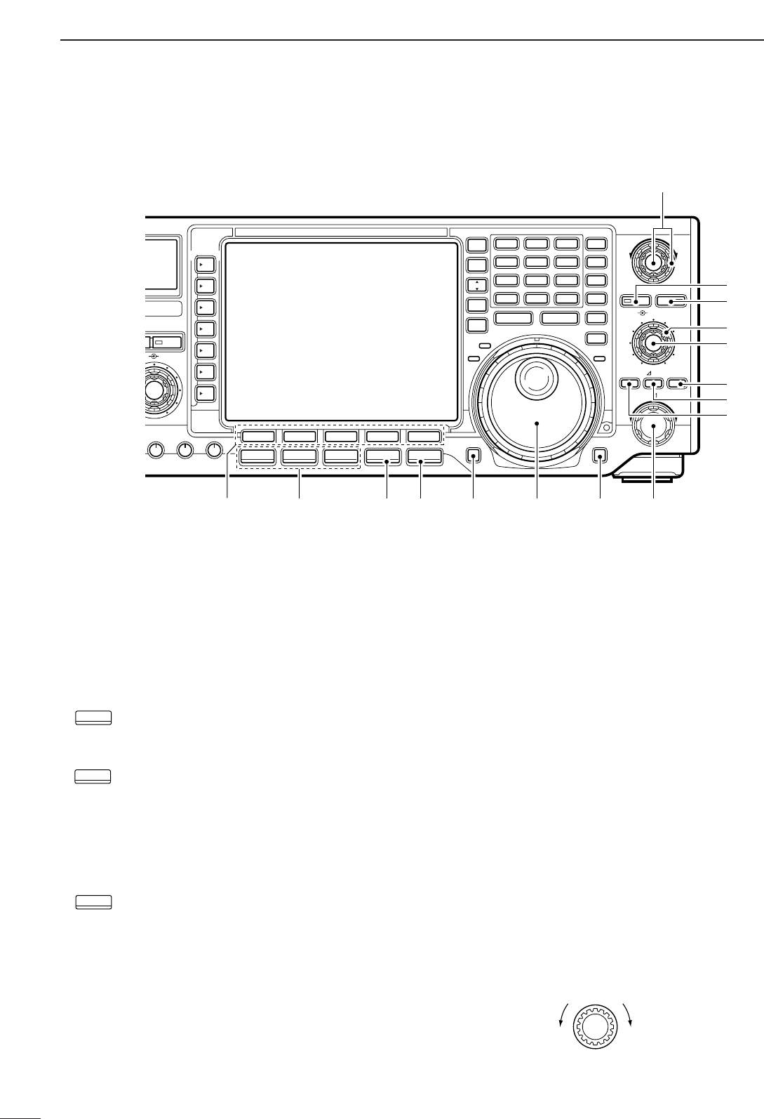
@1 LCD FUNCTION SWITCHES [F-1]–[F-5]
Push to select the function indicated in the LCD dis-
play above these switches.
•Functions vary depending on the operating condition.
@2 MODE SWITCHES
Selects the desired mode. (p. 29)
•Announces the selected mode when an optional UT-102
is installed. (pgs. 101, 104)
➥Selects USB and LSB mode alternately.
➥Selects SSB data mode (USB-D, LSB-D)
when pushed for 1 sec. in SSB mode.
➥Selects CW and RTTY mode alternately.
➥Switches CW and CW-R (CW reverse)
mode when pushed for 1 sec. in CW
mode.
➥Switches RTTY and RTTY-R (RTTY re-
verse) mode when pushed for 1 sec. in
RTTY mode.
➥Selects AM and FM mode alternately.
➥Selects AM/FM data mode (AM-D, FM-D)
when pushed for 1 sec. in AM or FM
mode.
@3 FILTER SWITCH [FILTER] (p. 61)
➥Push to select one of 3 IF filter settings.
➥Push for 1 sec. to enter the filter set mode.
@4 EXIT/SET SWITCH [EXIT/SET]
➥Push to exit from a set mode, etc.
➥Push for 1 sec. to enter the set mode screen.
(p. 92)
@5 REC/PLAY SWITCH [REC/PLAY] (p. 72)
➥Push momentarily to playback the recorded con-
tents in the channel R4 of the voice memory.
➥Push for 1 sec. to record the receiving signal con-
tents into the channel R4 (max. 15 sec.) of the
voice memory.
@6 TUNING DIAL (p. 25)
Changes the displayed frequency, selects set mode
settings, etc.
@7 LOCK/SPEECH SWITCH [LOCK/SPEECH]
➥Push momentarily to toggle the dial lock function
ON and OFF. (p. 64)
➥Push for 1 sec. to announce the S-meter indica-
tion and the selected readout frequency when an
optional UT-102 is installed. (p. 104)
@8 RIT/∂∂TX CONTROL [RIT/∂∂TX] (pgs. 58, 68)
Shifts the receive and/or transmit frequency without
changing the transmit and/or receive frequency
while the RIT and/or ∂TX functions are ON.
•Rotate the control clockwise to increase the frequency,
or rotate the control counterclockwise to decrease the
frequency.
•The shift frequency range is ±9.999 kHz in 1 Hz steps
(or ±9.99 kHz in 10 Hz steps).
RIT/∂TX
Low shift High shift
AM/FM
CW/RTTY
SSB
NB NR
BAL NR
COMP BK-IN DELAY KEY SPEED
LOCKTX
RX
TWIN PBT
CW PITCH
F-1 F-2 F-3 F-4 F-5
REC/PLAY
LOCK/SPEECH
RIT/ TX
TXRIT CLEAR
SPLIT
MP-W MP-R
DUAL
WATCH
VFO/
MEMO
MAIN/
SUB
M.SCOPE
CHANGE
1.8 3.5 7
10 14 18
21 24 28
GENE
•50
123
456
789
0
F-INPENT
Y
Z
MW
M-CL
TS
XFC
EIVER
i7500
PBT CLR NOTCH
NOTCH
SSB
CW/RTTY
AM/FM FILTER EXIT/SET
@2 @4@3 @5 @6
#6
#1
#2
#3
#0
#4
#5
@9
@8
@7
@1
6
1
PANEL DESCRIPTION
1
@9 RIT SWITCH [RIT] (p. 58)
➥Turns the RIT function ON and OFF when
pushed.
•Use the [RIT/∂TX] control to vary the RIT frequency.
➥Adds the RIT shift frequency to the operating fre-
quency when pushed for 1 sec.
✔
What is the RIT function?
The RIT (Receiver Incremental Tuning) shifts the receive fre-
quency without shifting the transmit frequency.
This is useful for fine tuning stations calling you on an off-fre-
quency or when you prefer to listen to slightly different-
sounding voice characteristics, etc.
#0 ∂∂TX SWITCH [∂∂TX] (p. 68)
➥Turns the ∂TX function ON and OFF when
pushed.
•Use the [RIT/∂TX] control to vary the ∂TX frequency.
➥Adds the ∂TX shift frequency to the operating
frequency when pushed for 1 sec.
✔
What is the
∂∂
TX function?
The ∂TX shifts the transmit frequency without shifting the re-
ceive frequency. This is useful for simple split frequency op-
eration in CW, etc.
#1 CLEAR SWITCH [CLEAR] (pgs. 58, 68)
Clears the RIT/∂TX shift frequency when pushed
for 1 sec. (default).
•The response time (for 1 sec. or momentarily) can be
selected on the quick RIT/∂TX clear setting (p. 102).
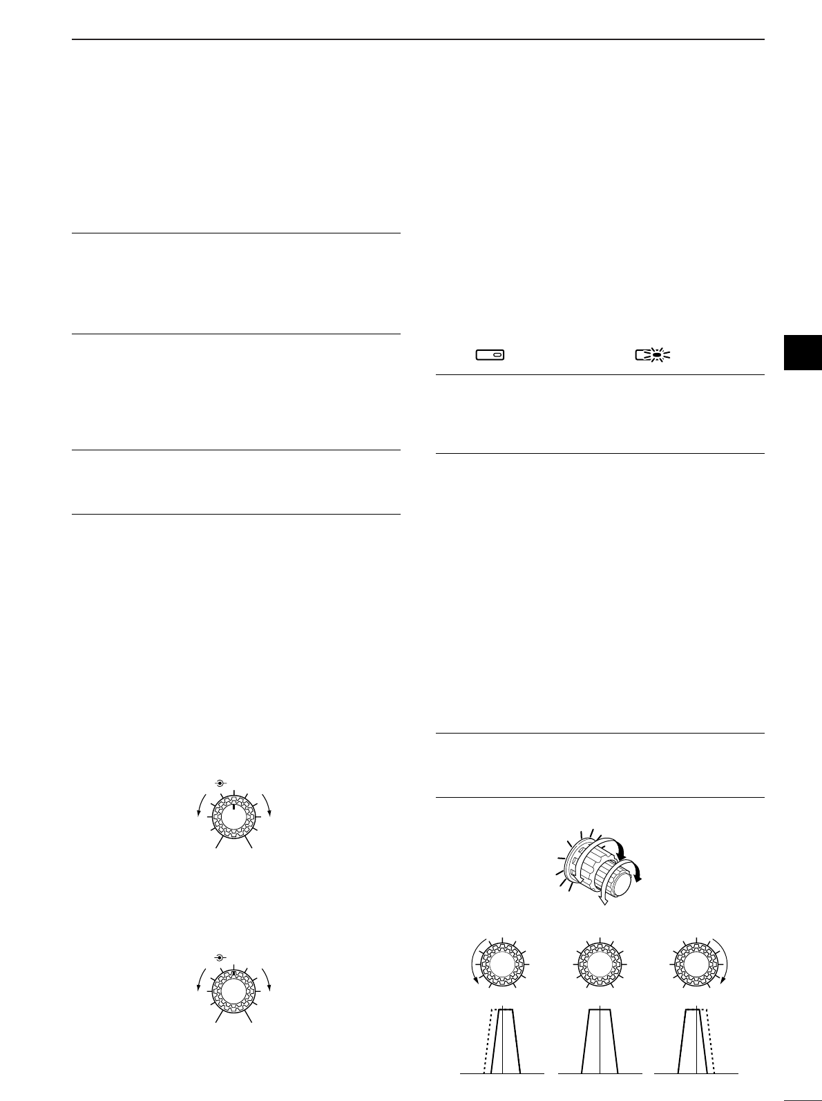
#2 MANUAL NOTCH FILTER CONTROL [NOTCH]
(inner control; p. 64)
Varies the peak frequency of the manual notch fil-
ter to pick out a receive signal from interference
while the manual notch function is ON.
•Notch filter center frequency:
SSB : 0 Hz to 5100 Hz
CW : CW pitch freq.–900 Hz to CW pitch freq.
+4200 Hz
AM : –5100 Hz to 5100 Hz
#3 CW PITCH CONTROL [CW PITCH]
(outer control; p. 36)
Shifts the received CW audio pitch and monitored
CW audio pitch without changing the operating fre-
quency.
#4 NOTCH SWITCH [NOTCH] (p. 64)
➥Switches the notch function between auto, man-
ual and OFF in SSB and AM modes.
➥Turns the manual notch function ON and OFF
when pushed in CW mode.
➥Turns the auto notch function ON and OFF when
pushed in FM mode.
•“AN” appears on the display when auto notch is in
use.
•“MN” appears on the display when manual notch is in
use.
•The [NOTCH] indicator in this switch lights green
when the function is activated.
✔
What is the notch function?
The notch function eliminates unwanted CW or AM carrier
tones while preserving the desired signal’s audio response.
The filtering frequency is adjusted to effectively eliminate un-
wanted tones via the DSP circuit.
#5 PBT CLEAR SWITCH [PBT CLR] (p. 60)
Clears the PBT settings when pushed for 1 sec.
•The [PBT CLR] indicator in this switch lights green when
PBT is in use.
#6 PASSBAND TUNING CONTROLS [TWIN PBT]
Adjust the receiver’s “passband width” of the DSP
filter. (p. 60)
•Passband width and shift frequency are displayed in the
LCD.
•Push [PBT CLR] for 1 sec. to clear the settings when not
in use.
•Variable range is set to half of the IF filter passband
width. 25 Hz steps and 50 Hz steps are available.
•These controls function as an IF shift control while in AM
mode and when the RTTY filter is turned ON. Only the
inner control may function in this case.
✔
What is the PBT control?
General PBT function electronically narrows the IF passband
width to reject interference. This transceiver uses the DSP
circuit for the PBT function.
PBT1
PBT2
TWIN PBT
Low cut High cutCenter
TWIN PBT TWIN PBT TWIN PBT
–+
NOTCHNOTCH
Notch OFF Notch ON
Approx. 300 Hz Approx. 900 Hz
Lower frequency Higher frequency
NOTCH
CW PITCH
NOTCH
CW PITCH
Lower frequency Higher frequency
7
1PANEL DESCRIPTION
■Front panel (continued)
#7 TRANSMIT INDICATOR [TX]
Lights red while transmitting.
#8 RECEIVE INDICATOR [RX]
Lights green while receiving a signal and when the
squelch is open.
#9 LOCK INDICATOR [LOCK] (p. 64)
Lights red when the dial lock function is activated.
$0 TRANSMIT FREQUENCY CHECK SWITCH
[XFC]
Monitors the transmit frequency when pushed and
held during the split frequency operation.
•While pushing this switch, the transmit frequency can be
changed with the tuning dial, keypad, memo pad or the
[Y]/[Z] switches.
•When the split lock function is turned ON, pushing [XFC]
cancels the dial lock function. (p. 99)
$1 QUICK TUNING SWITCH [TS] (p. 26)
➥Turns the quick tuning step ON and OFF.
•While the quick tuning indicator, “Z,” is displayed
above the frequency indication, the frequency can be
changed in programmed kHz steps.
•0.1, 1, 5, 9, 10, 12.5, 20 and 25 kHz quick tuning
steps are available for each operating mode indepen-
dently.
➥When the quick tuning step is OFF, push for 1
sec. to turn the 1 Hz tuning step ON and OFF.
•1 Hz indications appear in both readouts and the fre-
quency can be changed in 1 Hz steps.
➥When the quick tuning step is ON, push for 1 sec.
to enter the quick tuning step set mode.
$2 MEMORY CLEAR SWITCH [M-CL] (p. 80)
Clears the selected readout memory channel con-
tents when pushed for 1 sec. in memory mode.
•The channel becomes a blank channel.
•This switch does not function in VFO mode.
$3 MEMORY WRITE SWITCH [MW] (p. 72)
Stores the selected readout frequency and operat-
ing mode into the displayed memory channel when
pushed for 1 sec.
•This function is available both in VFO and memory
modes.
$4 MEMORY UP/DOWN SWITCHES [YY]/[ZZ](p. 76)
➥Push to select the memory channel number for
the selected readout.
•Memory channels can be selected both in VFO and
memory modes.
➥Select the desired memory channel directly after
pushing [F-INP] and a memory channel number.
$5 MEMO PAD-READ SWITCH [MP-R] (p. 81)
Each pushing calls up a frequency and operating
mode in a memo pad. The 5 (or 10) most recently
programmed frequencies and operating modes can
be recalled, starting from the most recent.
•The memo pad capacity can be expanded from 5 to 10
in set mode for your convenience. (p. 101)
BWBW 2.4k2.4k SFTSFT 0
FIL2FIL2
qw:pp
TXTX
CWCW
qr.qpp.pp
21.076.5021.076.50
VFOVFO
USBUSB
1
METER
Po
ANT
1
Quick tuning indicator
NB NR
BAL NR
COMP BK-IN DELAY KEY SPEED
LOCKTX
RX
TWIN PBT
CW PITCH
F-1 F-2 F-3 F-4 F-5
REC/PLAY
LOCK/SPEECH
RIT/ TX
TXRIT CLEAR
SPLIT
MP-W MP-R
DUAL
WATCH
VFO/
MEMO
MAIN/
SUB
M.SCOPE
CHANGE
1.8
1
3.5
2
7
3
10
4
14
5
18
6
21
7
24
8
28
9
GENE
50
0
F-INP
ENT
Y
Z
MW
M-CL
TS
XFC
CEIVER
PBT CLR NOTCH
NOTCH
SSB
CW/RTTY
AM/FM FILTER EXIT/SET
%2 %1 $7 $5
$6$9%0 $8
#7 #8 #9
$4
%3
$3
$2
$1
$0

8
1
PANEL DESCRIPTION
$6 KEYPAD
➥Pushing a key selects the operating band.
•[GENE•] selects the general coverage band.
➥Pushing the same key 2 or 3 times calls up other
stacked frequencies in the band. (p. 24)
•Icom’s triple band stacking register memorizes 3 fre-
quencies in each band.
➥After pushing [(F-INP)ENT], enters a keyed fre-
quency or memory channel. Pushing [(F-
INP)ENT] or [Y]/[Z] is necessary at the end.
(pgs. 25, 76)
•e.g. to enter 14.195 MHz, push [(F-INP)ENT] [1] [4]
[•] [1] [9] [5] [(F-INP)ENT].
$7 MEMO PAD-WRITE SWITCH [MP-W] (p. 81)
Programs the selected readout frequency and op-
erating mode into a memo pad.
•The 5 most recent entries remain in memo pads.
•The transmit frequency is programmed when pushed to-
gether with [XFC].
•The memo pad capacity can be expanded from 5 to 10
in set mode for your convenience. (p. 101)
$8 SPLIT SWITCH [SPLIT] (p. 70)
➥Turns the split function ON and OFF when
pushed.
➥Turns the split function ON, equalizes the sub
readout frequency to the main readout and sets
the sub readout for frequency input when pushed
for 1 sec. in non-FM modes. (Quick split function)
•The offset frequency is shifted from the main readout
frequency in FM mode. (pgs. 52, 99)
•The quick split function can be turned OFF using set
mode. (p. 98)
➥Turns the split function ON and shifts the sub
readout frequency after inputting an offset
(±4 MHz in 1 kHz steps).
$9 DUALWATCH SWITCH [DUALWATCH] (p. 63)
➥Turns the dualwatch function ON and OFF when
pushed.
➥Turns the dualwatch function ON and equalizes
the sub readout frequency to the main readout
when pushed for 1 sec. (Quick dualwatch function)
•The quick dualwatch function can be turned OFF
using set mode. (p. 98)
%0 MAIN/SUB CHANGE SWITCH [CHANGE]
➥Switches the frequency and selected memory
channel between main and sub readouts when
pushed.
•Switches between transmit frequency and receive fre-
quency when the split frequency function is ON.
(p. 70
➥Equalizes the sub readout frequency to the main
readout frequency when pushed for 1 sec.
%1 VFO/MEMORY SWITCH [VFO/MEMO]
➥Switches the selected readout operating mode
between the VFO mode and memory mode when
pushed. (pgs. 23, 76)
➥Transfers the memory contents to VFO when
pushed for 1 sec. (p. 79)
%2 MAIN/SUB•M.SCOPE SWITCH
[MAIN/SUB•M.SCOPE]
➥Push momentarilly to select access to the main
or sub readout.
•The sub readout frequency is displayed in outline or
mesh font. The sub readout functions only during split
operation or dualwatch.
➥Push for 1 sec. to turn the mini spectrum scope
screen indication ON and OFF.
•The mini spectrum scope screen can be indicated
with another screen, such as memory, set mode
screen, simultaneously.
%3 LCD FUNCTION DISPLAY (See p. 9 for details.)
Shows the operating frequency, function switch
menus, spectrum scope screen, memory channel
screen, set mode settings, etc.
9
1PANEL DESCRIPTION
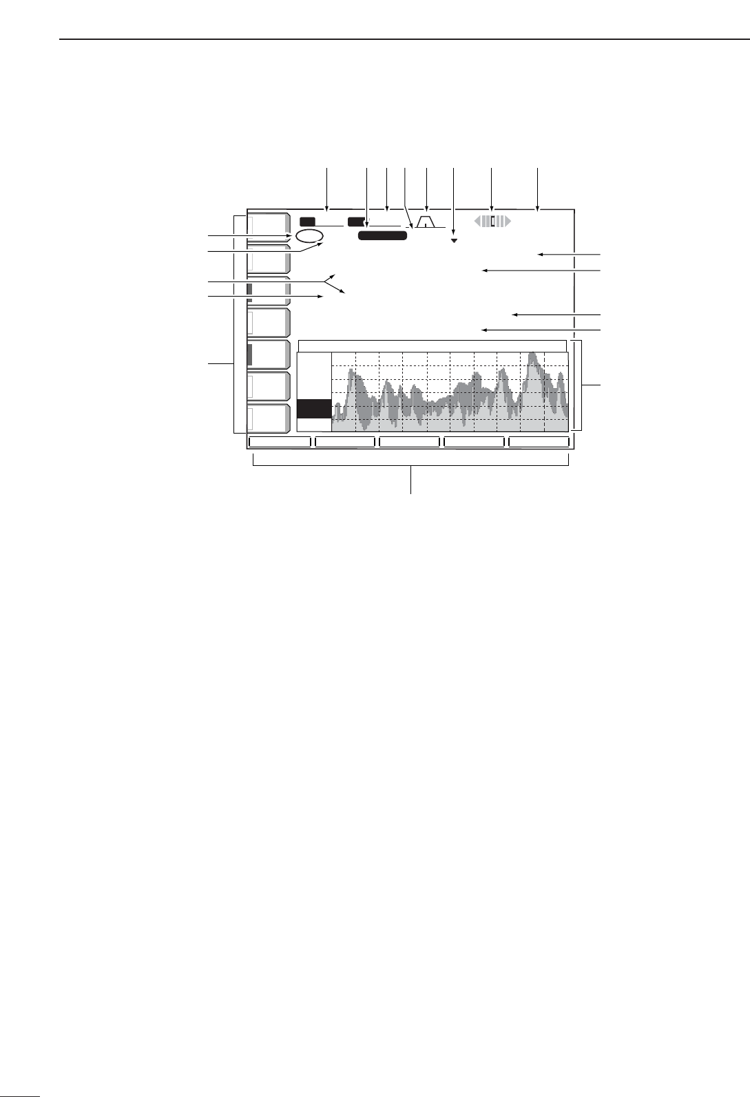
■LCD display
qTX INDICATOR
Indicates the frequency readout for transmission.
wVFO/MEMORY CHANNEL INDICATOR
(pgs. 23, 76)
Indicates the VFO mode or selected memory chan-
nel number.
eSELECT MEMORY CHANNEL INDICATOR (p. 85)
Indicates the displayed memory channel is set as a
select memory channel.
rMULTI-FUNCTION SWITCH GUIDE
Indicates the function of the multi-function switches.
tLCD FUNCTION SWITCH GUIDE
Indicates the function of the LCD function switches
([F-1] – [F-5]).
yMULTI-FUNCTION SCREEN (p. 10)
Shows the screens for the multi-function digital
meter, spectrum scope, voice recorder, memory
channel, scan, memory keyer, RTTY decoder, IF fil-
ter selection or set modes, etc.
uMEMORY CHANNEL READOUTS (p. 76)
➥Show the selected memory channel contents in
VFO mode.
➥Show the VFO contents in memory mode.
iFREQUENCY READOUTS (p. 25)
Show the operating frequency.
•Outline characters are used for non-accessing readout.
oCLOCK READOUT (p. 90)
Shows the current time.
•Dualtime indication is available.
!0 RTTY TUNING INDICATOR (p. 47)
Shows the tuning level in RTTY mode.
!1 QUICK TUNING INDICATOR (p. 26)
Appears when the quick tuning step function is in
use.
!2 PASSBAND WIDTH INDICATOR (p. 60)
Graphically displays the passband width for twin
PBT operation and center frequency for IF shift op-
eration.
!3 IF FILTER INDICATOR (p. 61)
Shows the selected IF filter number.
!4 SHIFT FREQUENCY INDICATOR (p. 60)
Shows the shift frequency of the IF filter.
!5 MODE INDICATOR (p. 29)
Shows the selected mode.
!6 BAND WIDTH INDICATOR (p. 61)
Shows the passband width of the IF filter.
ANT
1
COMP
OFF
WIDE
HOLD
SUB
MARKER
ATT
10dB
Grid
10k
10dB
SPAN ATT MARKER HOLD SET
METER
Po
P.AMP
1
AGC
MID
ATT
OFF
VOX
OFF
+12.5k
+12.5k
-12.5k
-12.5k
SPECTRUM SCOPE
SPECTRUM SCOPE
BW 2.4k SFT 0
USB
USB
qw:pp
we:pp
VFO 21.085.00
TX
CW
FIL2
qr.qqy.pp
qr.qpp.pp
56ß
USB
1ß 21.085.00 CW
VFO
FIL2
t
i
i
!6 !4!5 !2!3 !1 !0 o
y
u
u
r
q
w
e
w
10
1
PANEL DESCRIPTION
1
ATT
0FF
METER
Po
P.AMP
1
BK-IN
OFF
1/4
OFF
BW 2.4k SFT 0
VFO
FIL2
CW
qw:pp
AGC
MID
1
TX
VFO
1
USB
CW
CW
FIL2
qr.qpp.pp
qr.qpp.pp
--. ---. --
--. ---. --
SCOPE VOICE KEYER MEMORY SCAN
ANT
1
BK-INBK-IN
OFFOFF
1/41/4
OFFOFF
AGCAGC
MIDMID CQ TEST CQ TEST DE ICOM ICOMCQ TEST CQ TEST DE ICOM ICOM
TEST
QRZ?
CFM TUCFM TU
UR 5NNUR 5NN001 BK BK
M1M1
M2M2
M3M3
M4M4
M1 M2 M3 M4 -1
BK-IN
OFF
1/4
OFF
AGC
MID
T4 -
-
-
T1 -
-
-
T3 -
-
-
VOICE RECORDER
T2 -
-
-
TX MEMORY
T1 T2 T3 T4 T/R
BK-INBK-IN
OFFOFF
1/41/4
OFFOFF
AGCAGC
MIDMID GridGrid
2.5k2.5k
10dB10dB
+12. 5k+12. 5k
-12. 5k-12. 5k SPECTRUM SCOPESPECTRUM SCOPE
SPANSPAN ATTATT MARKERMARKER HOLDHOLD
SET
BK-INBK-IN
OFFOFF
1/41/4
OFFOFF
AGCAGC
MIDMID
SCANSCAN
∂FSpanSpan : ± 10kHz 10kHz
ProgrammedProgrammed P1:P1: 0.500.00MHz0.500.00MHz
scan edgesscan edges P2:P2: 29.999.99MHz29.999.99MHz
PROGPROG
∂F
FINEFINE
∂F SPANF SPAN SETSET
BK-INBK-IN
OFFOFF
1/41/4
OFFOFF
AGCAGC
MIDMID
SCANSCAN
∂FSpanSpan : ± 10kHz 10kHz
ProgrammedProgrammed P1:P1: 0.500.00MHz0.500.00MHz
scan edgesscan edges P2:P2: 29.999.99MHz29.999.99MHz
MEMOMEMO ∂FSELECTSELECT ∂F SPANF SPAN SETSET
THRESHOLD 9
RTTYRTTY
FILFIL
ONON
AGCAGC
MIDMID
RTTY DECODERTTY DECODE
MEMORY KEYERMEMORY KEYER
**** RTTY Decode Monitor ******** RTTY Decode Monitor ****
45bps BAUDOT Mark=2125,Shift=170 45bps BAUDOT Mark=2125,Shift=170
UnShift On Space support (SET-OTHERS) UnShift On Space support (SET-OTHERS)
New Line Code selectable (SET-OTHERS) New Line Code selectable (SET-OTHERS)
If RTTY-FIL is OFF, Please turn ON. If RTTY-FIL is OFF, Please turn ON.
1/41/4
OFFOFF
<MENU1><MENU1> HLD/CLRHLD/CLR TX MEMTX MEM ADJADJ WIDEWIDE
BK-INBK-IN
OFFOFF
1/41/4
OFFOFF
AGCAGC
MIDMID
MEMORYMEMORY
9999 --.---.----.---.-- ------------ ------
PP11000.500.000.500.00 USBUSB FL2 SCAN EDGEFL2 SCAN EDGE
P2P2 29.999.9929.999.99 USBUSB FL2 SCAN EDGEFL2 SCAN EDGE
1 1 --.---.----.---.-- ------------ ------
2 2 --.---.----.---.-- ------------ ------
33--.---.----.---.-- ------------ ------
4 4 --.---.----.---.-- ------------ ------
ROLLROLL SETSET SELECTSELECT NAMENAME WIDEWIDE
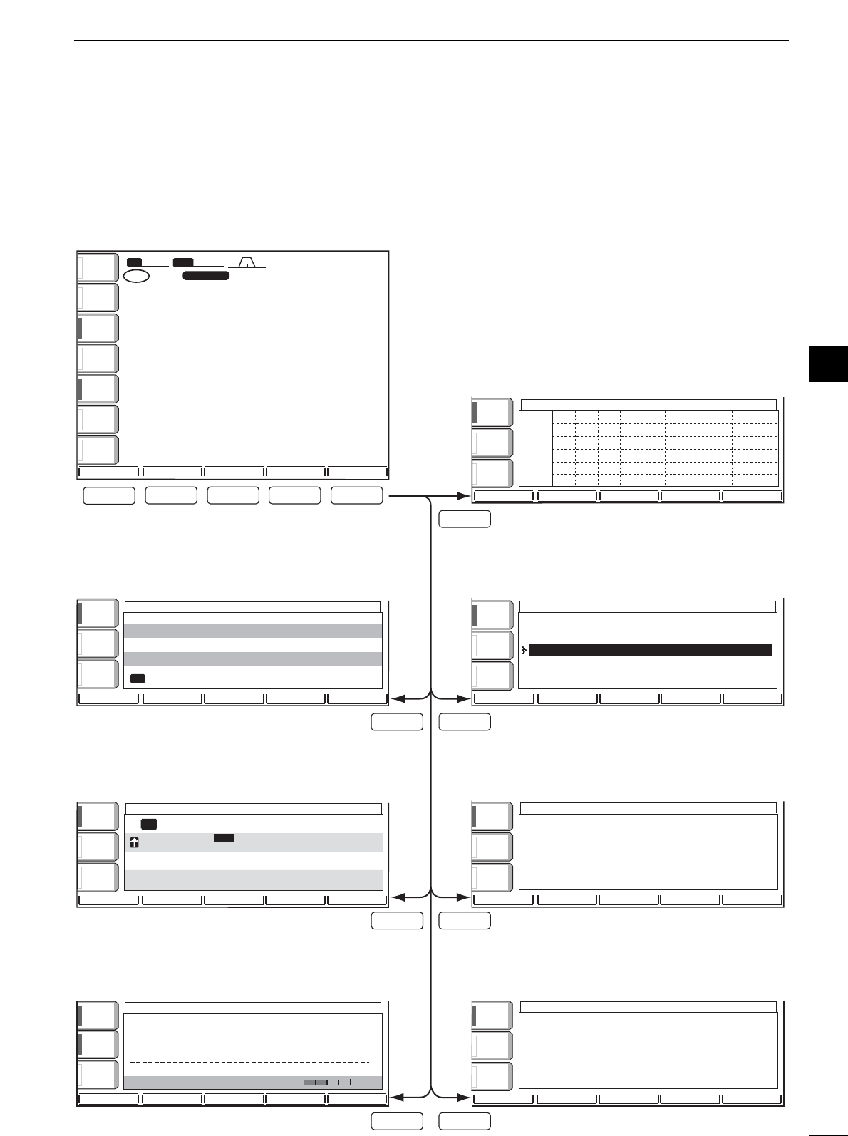
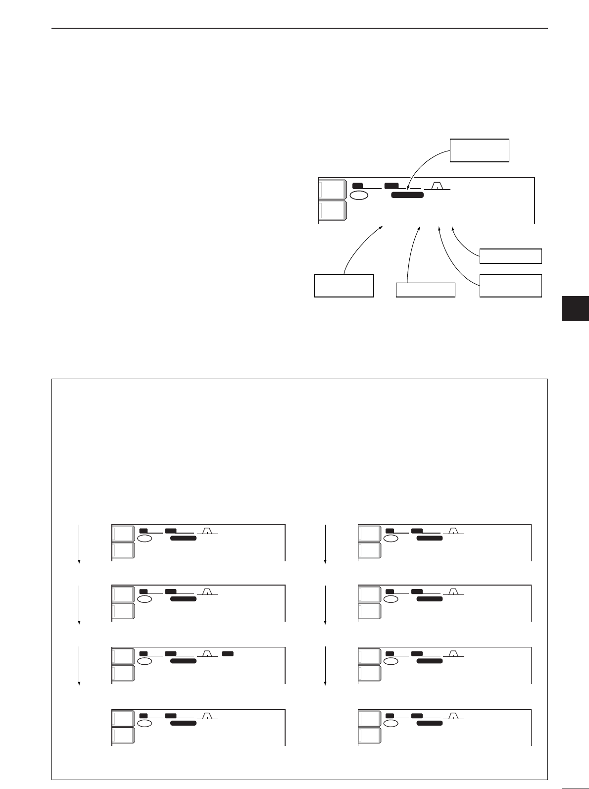
• Start up screen
• Voice recorder screen (p. 72)
• Memory keyer screen (CW mode: p. 40)
• Spectrum scope screen (p. 55)
• Memory channel screen (p. 77)
• Programmed scan screen (VFO mode: p. 83)
• RTTY decoder screen (RTTY mode: p. 46) • Memory scan screen (Memory mode: p. 84)
F-1
F-1
F-4F-2
F-5
F-3
F-5
F-3
F-2 F-3 F-4 F-5
■Screen menu arrangement
The following screens can be selected from the start
up screen. Choose the desired screen using the fol-
lowing chart.
Pushing [EXIT/SET] several times returns to the start
up screen. See p. 92 for set mode arrangement.
11
1PANEL DESCRIPTION
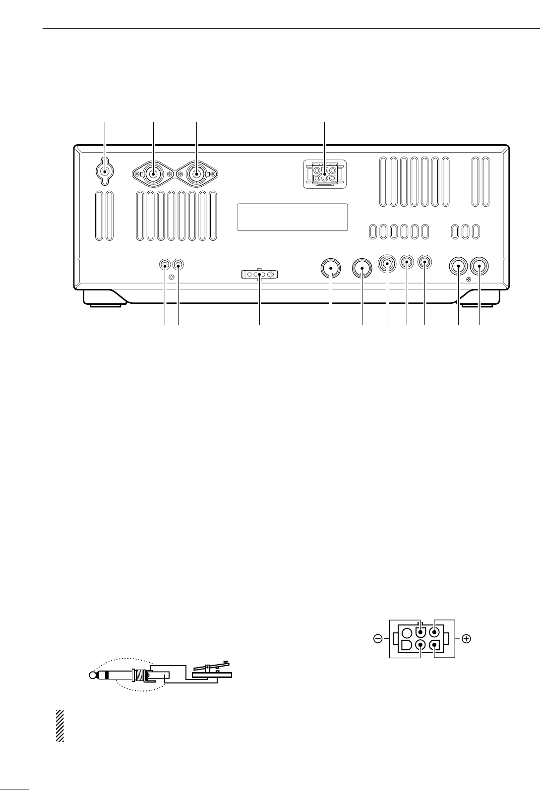
■Rear panel
qTRANSVERTER JACK [XVERT] (p. 18)
External transverter input/output jack. Activated by
voltage applied to [ACC(2)] pin 6.
wRECEIVE ANTENNA CONNECTOR [RX ANT]
(p. 15)
Connects a 50 Ωgeneral coverage antenna with an
RCA connector.
eTUNER CONTROL SOCKET [TUNER] (p. 15)
Accepts the control cable from an optional AH-4
HF/50 MHz AUTOMATIC ANTENNA TUNER or AH-3 HF
AUTOMATIC ANTENNA TUNER.
rACCESSORY SOCKET 1 [ACC(1)]
tACCESSORY SOCKET 2 [ACC(2)]
Enable connection of external equipment such as a
linear amplifier, an automatic antenna selector/
tuner, TNC for data communications, etc.
•See p.20 for socket information.
ySTRAIGHT KEY JACK [KEY] (p. 14)
Accepts a straight key or external electronic keyer
with 1⁄4inch standard plug.
•[ELEC-KEY] on the front panel can be used for a straight
key or external electronic keyer. Deactivate the internal
electronic keyer in keyer set mode. (p. 43)
If you use an external electronic keyer, make
sure the voltage retained by the keyer is less
than 0.4 V when the key is ON.
uCI-V REMOTE CONTROL JACK [REMOTE]
(p. 109)
➥Connects a PC via the optional CT-17
CI
-
VLEVEL
CONVERTER
for external control of the transceiver
functions.
➥Used for transceive operation with another Icom
CI-V transceiver or receiver.
iEXTERNAL SPEAKER JACK [EXT SP]
(pgs. 15, 114)
Accepts an 4–8 Ωspeaker.
oALC INPUT JACK [ALC] (p. 17)
Connects to the ALC output jack of a non-Icom lin-
ear amplifier.
!0 SEND CONTROL JACK [SEND] (p. 17)
Goes to ground while transmitting to control exter-
nal equipment such as a linear amplifier.
•Max. control level: 16 V DC/0.5 A
!1 DC POWER SOCKET [DC 13.8V] (p. 16)
Accepts 13.8 V DC through the supplied DC power
cable (OPC-025D).
Rear panel view
(+)
(_)
qw!0
!1
ertyuio
!4 !3 !2
12
1
PANEL DESCRIPTION
1
!2 ANTENNA CONNECTOR 1 [ANT1]
!3 ANTENNA CONNECTOR 2 [ANT2] (pgs. 13, 14)
Accept a 50 Ωantenna with a PL-259 connector.
When using an optional AH-4 HF/50 MHz AUTO-
MATIC ANTENNA TUNER or AH-3 HF AUTOMATIC AN-
TENNA TUNER, connect it to the [ANT1] connector.
The internal antenna tuner activates for [ANT2] and
deactivates for [ANT1] when connecting the AH-4 or
AH-3.
!4 GROUND TERMINAL [GND] (pgs. 13, 14)
Connect this terminal to a ground to prevent electri-
cal shocks, TVI, BCI and other problems.
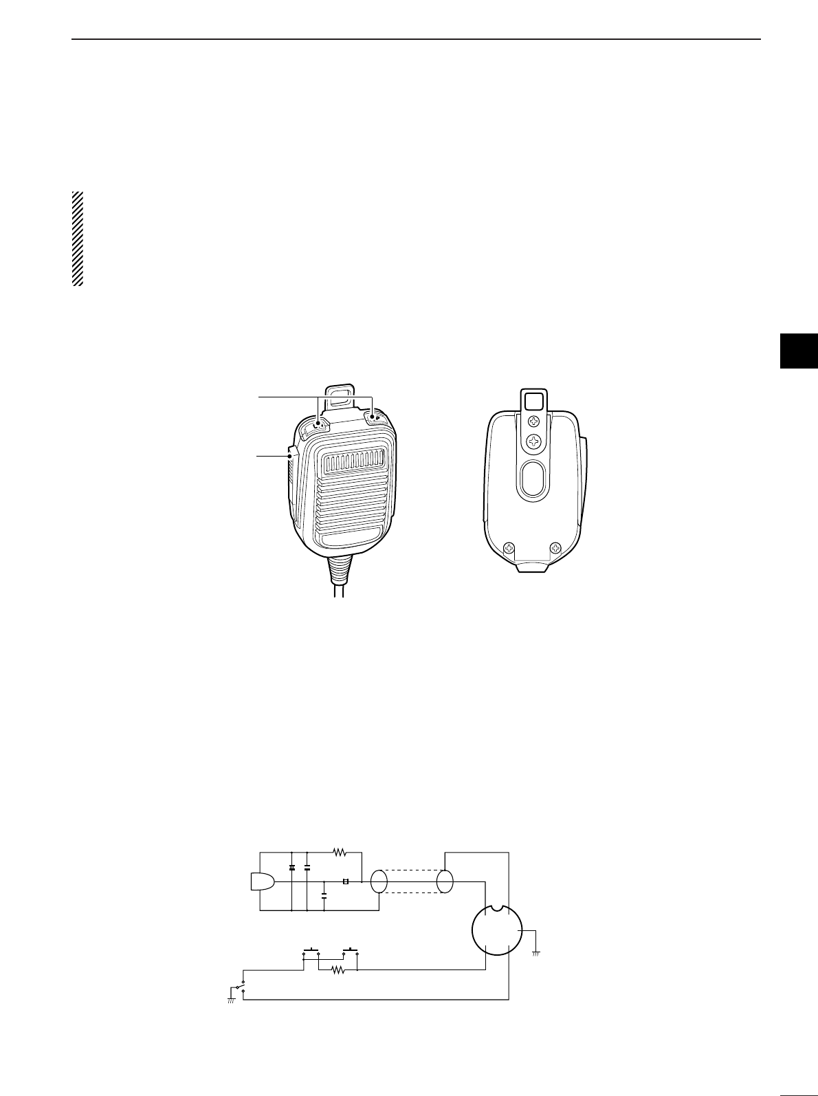
■Microphone (HM-36)
qUP/DOWN SWITCHES [UP]/[DN]
Change the selected readout frequency or memory
channel.
•Continuous pushing changes the frequency or memory
channel number continuously.
•While pushing [XFC], the transmit readout frequency can
be controlled while in spilt frequency operation.
•The [UP]/[DN] switch can simulate a key paddle. Preset
in the keyer set mode. (p. 43)
wPTT SWITCH
Push and hold to transmit; release to receive.
q
w
+
+
q
w
ert
y
u
i
4700p
4700p
10
0.33
MICROPHONE
MIC
ELEMENT
2k
470
DOWN UP
PTT RECEIVE
TRANSMIT
MICROPHONE CABLE MICROPHONE PLUG
• HM-36 SCHEMATIC DIAGRAM
2INSTALLATION AND CONNECTIONS
■Unpacking
After unpacking, immediately report any damage to the
delivering carrier or dealer. Keep the shipping cartons.
For a description and a diagram of accessory equip-
ment included with the IC-756PROIII, see ‘Supplied
accessories’ on p. i of this manual.
■Selecting a location
Select a location for the transceiver that allows ade-
quate air circulation, free from extreme heat, cold, or
vibrations, and away from TV sets, TV antenna ele-
ments, radios and other electromagnetic sources.
The base of the transceiver has an adjustable stand
for desktop use. Set the stand to one of two angles de-
pending on your operating conditions.
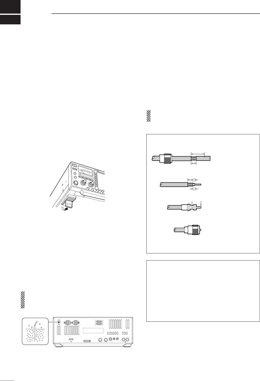
■Grounding
To prevent electrical shock, television interference
(TVI), broadcast interference (BCI) and other prob-
lems, ground the transceiver through the GROUND
terminal on the rear panel.
For best results, connect a heavy gauge wire or strap
to a long earth-sunk copper rod. Make the distance be-
tween the [GND] terminal and ground as short as pos-
sible.
RWARNING: NEVER connect the [GND]
terminal to a gas or electric pipe, since the connec-
tion could cause an explosion or electric shock.
■Antenna connection
For radio communications, the antenna is of critical im-
portance, along with output power and sensitivity. Se-
lect antenna(s), such as a well-matched 50 Ωantenna,
and feedline. 1.5:1 or better of Voltage Standing Wave
Ratio (VSWR) is recommended for your desired band.
Of course, the transmission line should be a coaxial
cable.
When using 1 antenna, use the [ANT1] connector.
CAUTION: Protect your transceiver from lightning
by using a lightning arrestor.
Antenna SWR
Each antenna is tuned for a specified frequency
range and SWR may be increased out-of-range.
When the SWR is higher than approx. 2.0:1, the
transceiver’s power drops to protect the final transis-
tor. In this case, an antenna tuner is useful to match
the transceiver and antenna. Low SWR allows full
power for transmitting even when using the antenna
tuner. The IC-756PROIII has an SWR meter to mon-
itor the antenna SWR continuously.
PL-259 CONNECTOR INSTALLATION EXAMPLE
30 mm ≈9⁄8in 10 mm ≈3⁄8in 1–2 mm ≈1⁄16 in
30 mm
10 mm (soft solder)
10 mm
1–2 mm
solder solder
Soft
solder
Coupling ring
Slide the coupling ring
down. Strip the cable
jacket and soft solder.
Slide the connector
body on and solder it.
Screw the coupling
ring onto the
connector body.
Strip the cable as
shown at left. Soft sol-
der the center con-
ductor.
q
w
e
r
13
2
14
INSTALLATION AND CONNECTIONS
2
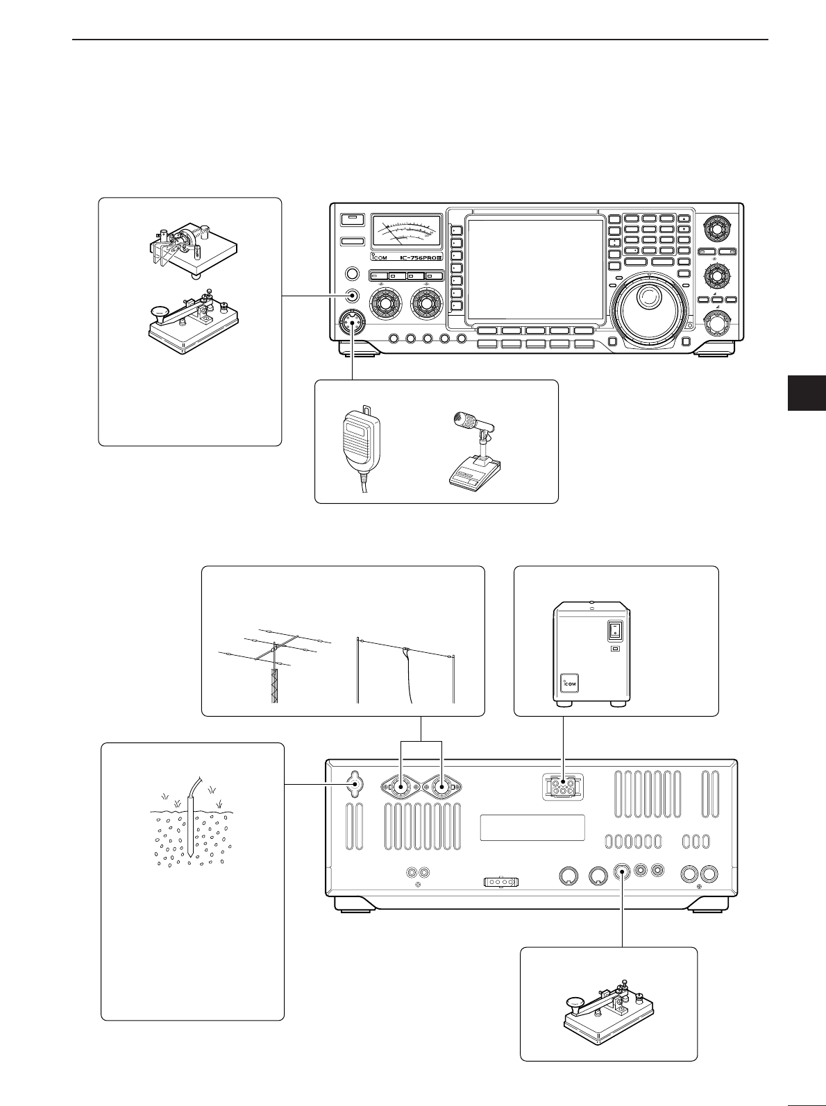
■Required connections
•Front panel
•Rear panel
SWR
S
COMP
ALC
Po
010
10
25 50 100
20
101.5 23
159+20 +40 +60dB
dB
RIT/ TX
TX
F-1
SSB
F-2 F-3 F-4 F-5
CW/RTTY
AM/FM FILTER EXIT/SET
123
456
789
0
ENT
NOTCH
PBT CLR
LOCKTX
RX
NOTCH
TWIN PBT
CW PITCH
REC/PLAY
LOCK/SPEECH
RIT CLEAR
SPLIT
MP-W MP-R
DUAL
WATCH
VFO/
MEMO
MAIN/
SUB
M.SCOPE
CHANGE
1.8 3.5 7
10 14 18
21 24 28
GENE
50 F-INP
MW
M-CL
TS
XFC
TIMER
POWER
TRANSMIT
PHONES
ELEC-KEY
MIC
TUNER MONITOR NB NR
AF BAL NRRF/SQL
MIC GAIN RF POWER COMP KEY SPEEDBK-IN DELAY
HF/50MHz TRANSCEIVER
CW KEY
A straight key can be used
when the internal electronic
keyer is turned OFF in keyer
set mode. (p. 43)
MICROPHONES (p. 114)
SM-20HM-36
GROUND (p. 13)
Use the heaviest gauge wire
or strap available and make
the connection as short as
possible.
Grounding prevents electrical
shocks, TVI and other
problems.
ANTENNA 1, 2 (p. 13)
[Example]: ANT1 for 1.8–18 MHz bands
ANT2 for 21–50 MHz bands
DC POWER SUPPLY (p.16)
STRAIGHT KEY
PS-125
15
2INSTALLATION AND CONNECTIONS
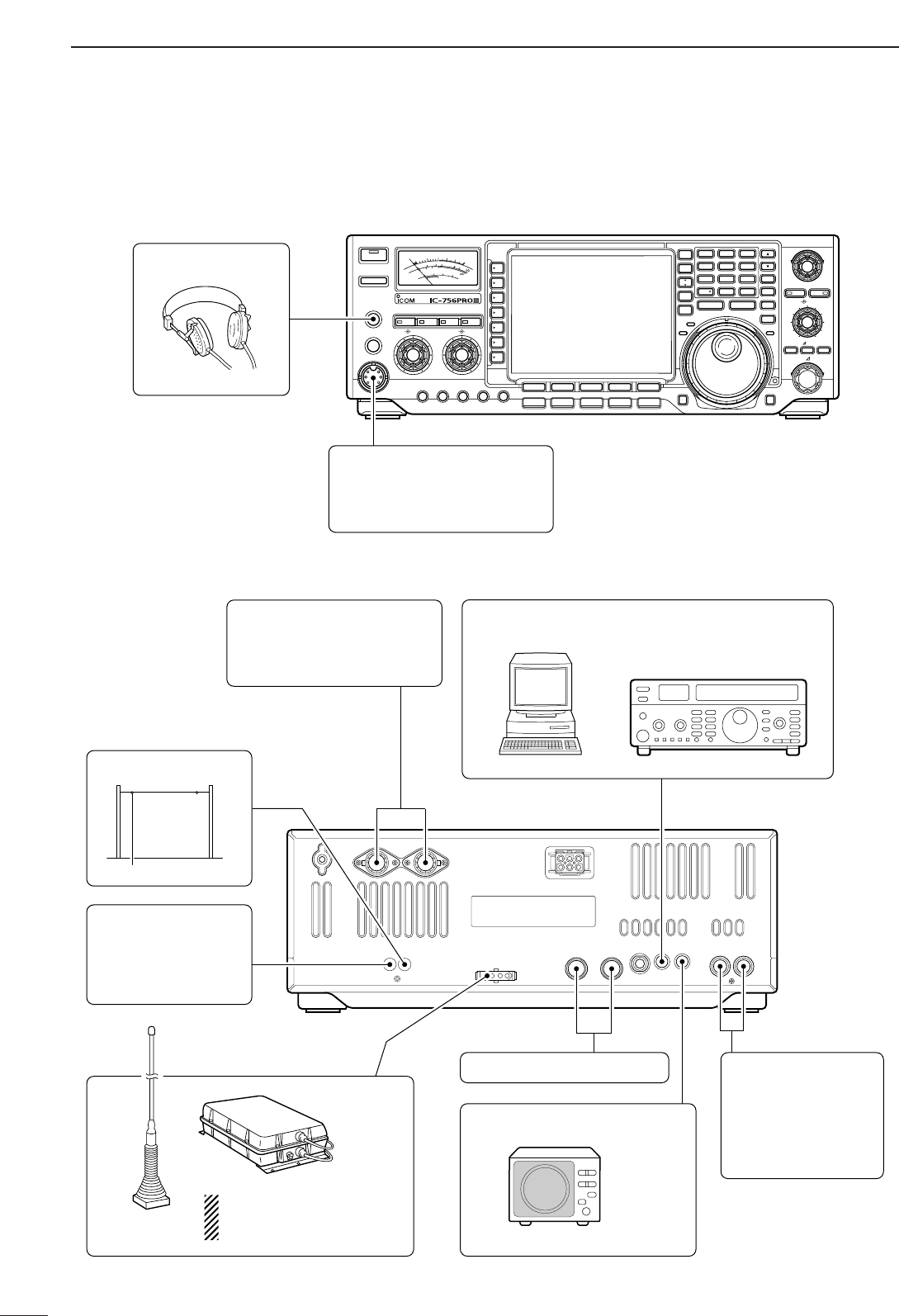
■Advanced connections
•Front panel
•Rear panel
SWR
S
COMP
ALC
Po
010
10
25 50 100
20
101.5 23
159+20 +40 +60dB
dB
RIT/ TX
TX
F-1
SSB
F-2 F-3 F-4 F-5
CW/RTTY
AM/FM FILTER EXIT/SET
123
456
789
0
ENT
NOTCH
PBT CLR
LOCKTX
RX
NOTCH
TWIN PBT
CW PITCH
REC/PLAY
LOCK/SPEECH
RIT CLEAR
SPLIT
MP-W MP-R
DUAL
WATCH
VFO/
MEMO
MAIN/
SUB
M.SCOPE
CHANGE
1.8 3.5 7
10 14 18
21 24 28
GENE
50 F-INP
MW
M-CL
TS
XFC
TIMER
POWER
TRANSMIT
PHONES
ELEC-KEY
MIC
TUNER MONITOR NB NR
AF BAL NRRF/SQL
MIC GAIN RF POWER COMP KEY SPEEDBK-IN DELAY
HF/50MHz TRANSCEIVER
HEADPHONES
MIC
The AFSK modulation signal
can be input from [MIC]. (p. 19)
ANTENNA 1, 2 (pgs. 17, 18)
Connects a linear amplifier,
antenna selector, etc.
EXTERNAL SPEAKER (p. 114)
ACC SOCKETS (pgs. 19, 20)
RX ANTENNA
TRANSVERTER
(p. 18)
Connects a transverter
for V/UHF band use.
SP-23
AH-4/AH-3
(p. 18)
AH-2b
[REMOTE] (p. 109)
Used for computer control and transceive operation.
[SEND], [ALC]
(p. 17)
Used for connecting a
non-Icom linear ampli-
fier.
When using the AH-4/AH-3,
it must be connected to the
[ANT1] connector.
16
2
INSTALLATION AND CONNECTIONS
2
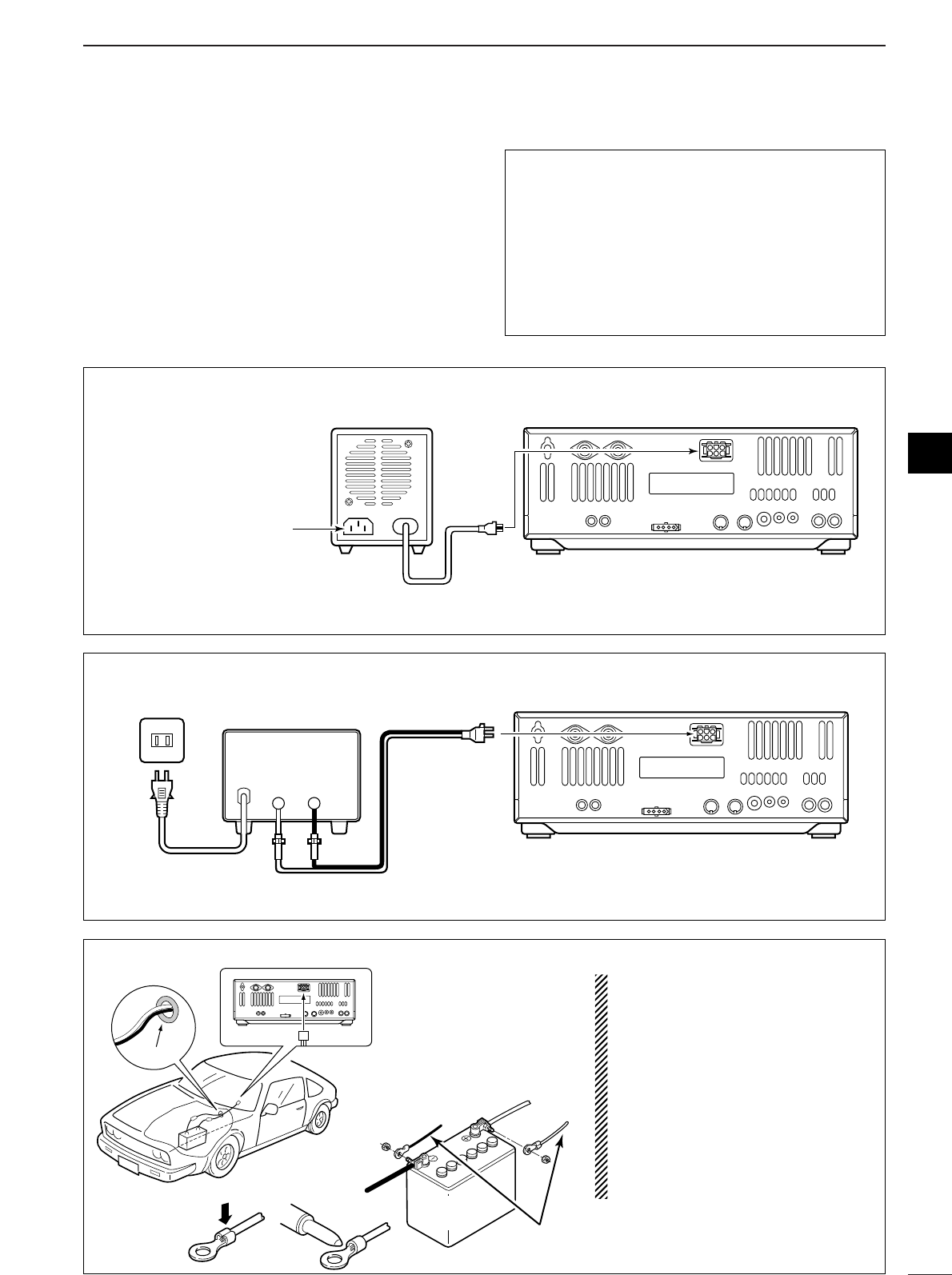
■Power supply connections
Use the optional PS-125 DC power supply with a 25 A
capacity when operating the transceiver with AC
power. Refer to the diagrams below.
CAUTION: Before connecting the DC power
cable, check the following important items. Make
sure:
•The [POWER] switch is OFF.
•Output voltage of the power source is 12–15 V
when you use a non-Icom power supply.
•DC power cable polarity is correct.
Red : positive +terminal
Black : negative _terminal
CONNECTING A DC POWER SUPPLY
to DC power
socket
A DC power supply
AC outlet
AC cable
30 A fuses
Supplied
DC power cable
13.8 V; at least 23 A
Black
_Red
+
Transceiver
CONNECTING A VEHICLE BATTERY
12 V
battery
Supplied
DC power cable
+ red
_ black
Crimp
Solder
Grommet
NOTE: Use terminals for
the cable connections.
RWARNING NEVER con-
nect to a battery without supplied
DC fuses, otherwise a fire hazard
may occur.
NEVER connect the transceiver
directly to a 24 V battery.
IMPORTANT! Detailed installation
notes for Icom mobile transceivers to
be fitted into vehicles are available.
Contact your Icom dealer or distribu-
tor.
CONNECTING PS-125 DC POWER SUPPLY
PS-125
Connect to an AC outlet
using the supplied AC cable.
DC power cable
DC power
socket
Transceiver
17
2INSTALLATION AND CONNECTIONS
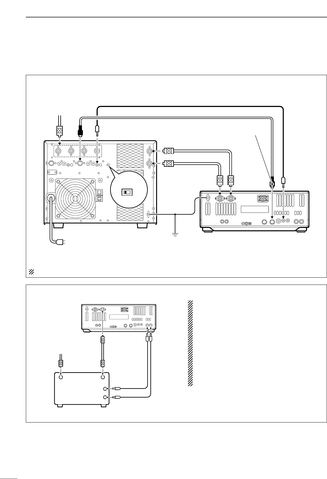
■Linear amplifier connections Use the [ANT1] connector when connecting a linear
amplifier.
CONNECTING THE IC-PW1
Turn OFF the transceiver’s antenna tuner while tuning the IC-PW1’s tuner.
To an
antenna ACC-1
ANT
ANT2 ANT1 ACC(2)
INPUT1
INPUT2
REMOTE
EXCITER
11&2
GND
GND
IC-PW1
AC outlet
(Non-European versions: 100–120/220–240 V
European version : 230 V)
Ground Transceiver
REMOTE
Remote control cable (supplied with the IC-PW1)
ACC cable (supplied with the IC-PW1)
Be sure to connect the cable
to the 7-pin ACC(2) jack.
Coaxial cable
(supplied with the IC-PW1)
Coaxial cable
(optional)
Connect
[INPUT2]
if necessary
CONNECTING A NON-ICOM LINEAR AMPLIFIER
RWARNING:
Set the transceiver output power and linear amplifier
ALC output level referring to the linear amplifier in-
struction manual.
The ALC input level must be in the range 0 V to –4 V,
and the transceiver does not accept positive voltage.
Non-matched ALC and RF power settings could cause
a fire or ruin the linear amplifier.
The specifications for the SEND relay are 16 V DC
0.5 A. If this level is exceeded, a large external relay
must be used.
RF OUTPUT RF INPUT
ALC
SEND
50 ‰ coaxial
cable
Transceiver
ANT1 ALC SEND
To an
antenna
Non-Icom linear amplifier
18
2
INSTALLATION AND CONNECTIONS
2
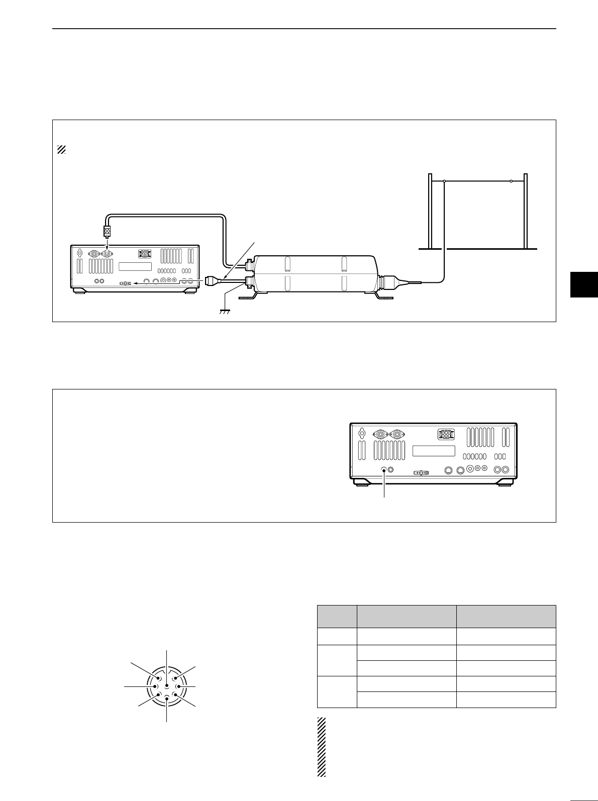
■External antenna tuner connection
CONNECTING THE AH-4/AH-3
The AH-4 or AH-3 must be connected to [ANT1].
Coaxial cable (from the AH-4 or AH-3)
ANT1 Control cable
Transceiver Ground AH-4 or AH-3
Long wire or optional AH-2b
(Front panel view)
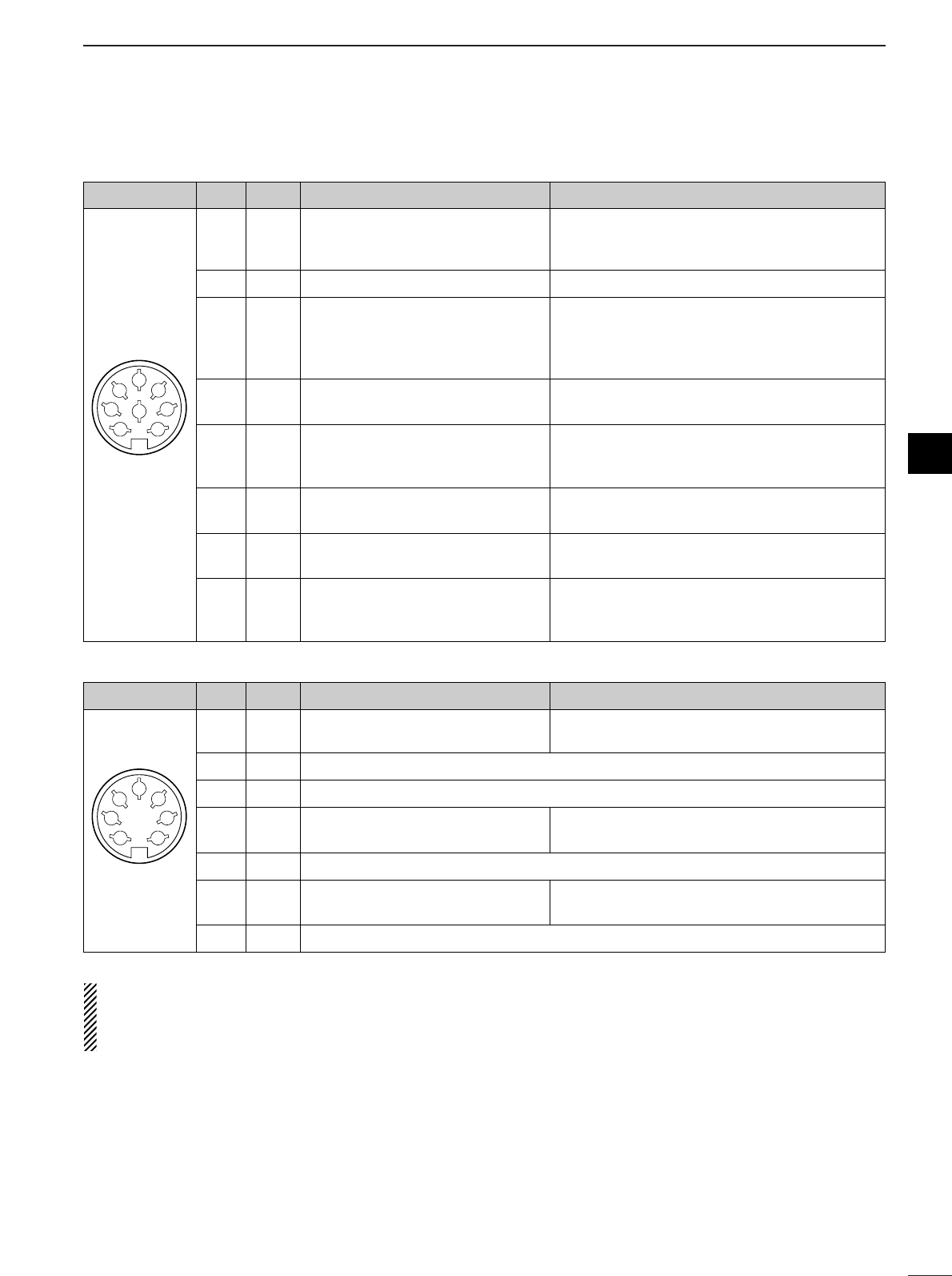
CAUTION: DO NOT short pin 2 to ground as this
can damage the internal 8 V regulator.
NOTE: DC voltage is applied to pin 1 for micro-
phone operation. Take care when using a non-Icom
microphone.
y GND (PTT ground)
t PTT
r Main readout squelch switch
q Microphone input
w +8 V DC output
e Frequency up/down
u GND
(Microphone ground)
i Main readout AF output
(varies with [AF]/[BAL])
[MIC] FUNCTION DESCRIPTION
Pin No.
w+8 V DC output Max. 10 mA
e
Frequency up Ground
Frequency down Ground through 470 Ω
rSquelch open “Low” level
Squelch closed “High” level
■Microphone connector information
When 2 to 13.8 V is applied to pin 6 of [ACC(2)], the
[XVERT] jack is activated for transverter operation
and the antenna connectors do not receive or trans-
mit any signals. (p. 20)
While receiving, the [XVERT] jack can be activated as
an input terminal from an external transverter.
While transmitting, the [XVERT] jack outputs signals
of the displayed frequency at –20 dBm (22 mV) as
signals for the external transverter.
Transverter jack
■Transverter jack information
19
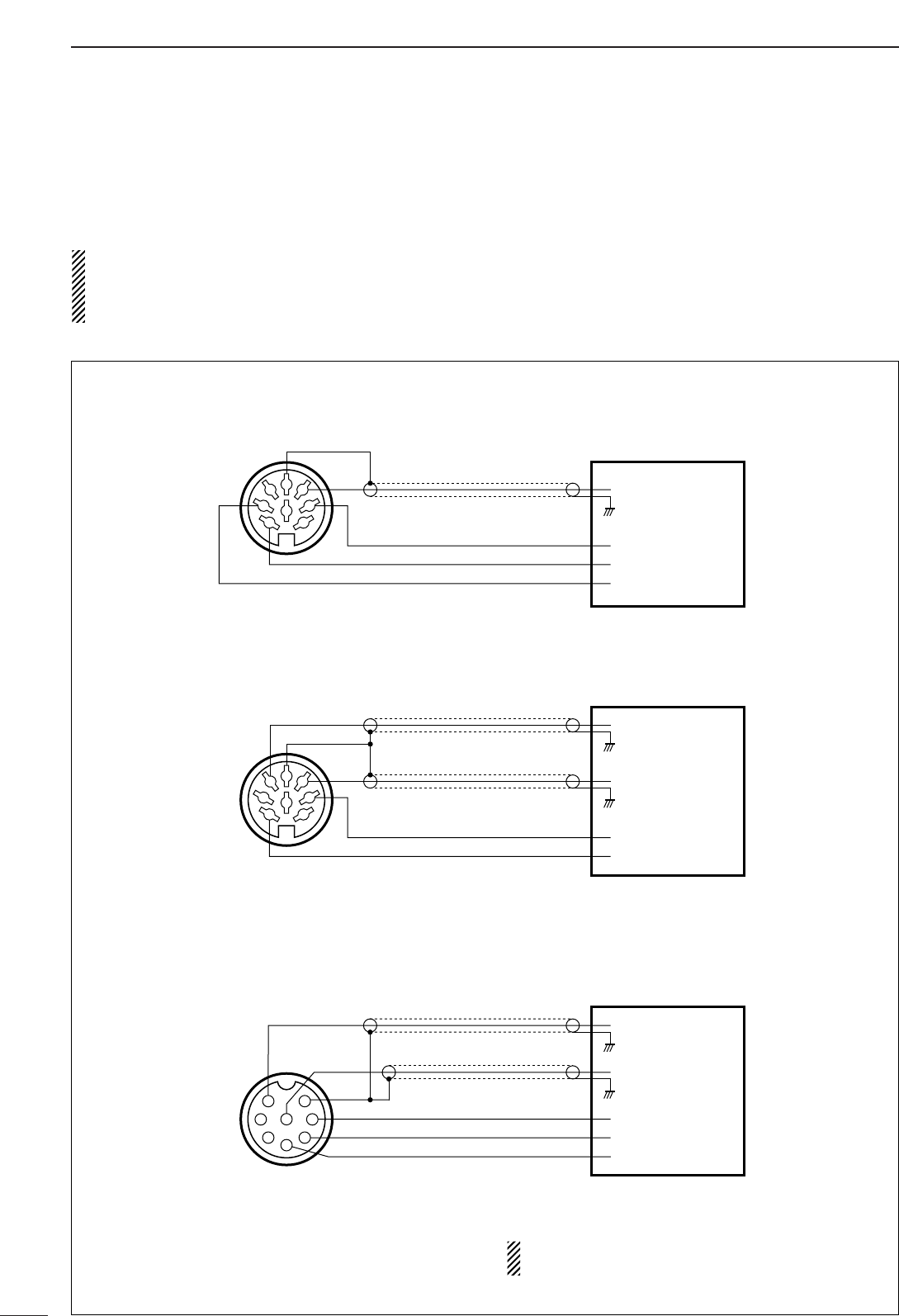
2INSTALLATION AND CONNECTIONS
AF input
Ground (GND)
PTT
SQUELCH input*
RTTY keying
* Connect the SQUELCH line when required.
Terminal unit (TU) or
Terminal Node Controller (TNC)
[ACC(1)] socket
(Rear panel view)
1
2
3
45
67
8
AFSK output
AF input
Ground (GND)
Ground (GND)
PTT
SQUELCH input*
* Connect the SQUELCH line when required.
Terminal Node Controller (TNC)
or Scan converter
[ACC(1)] socket
(Rear panel view)
1
2
3
45
67
8
AF input
Ground (GND)
AFSK output
PTT
SQUELCH input*
* Connect the SQUELCH line when required.
Terminal Node Controller (TNC)
or Scan converter
[MIC] connector
(Front panel view)
1
2
345
6
7
8
■FSK and AFSK (SSTV) connections
To connect a terminal unit, TNC or scan converter,
refer to the diagram below.
For RTTY operation:
Narrow filter settings may not pass RTTY signals.
Be sure to select the appropriate IF filter settings
corresponding to the signal width. (p. 61)
FSK (RTTY) connection
Use RTTY mode for
operation
AFSK and SSTV connections
Use SSB or FM mode
for operation
AFSK and SSTV connections via microphone connector
Use SSB or FM mode
for operation
When connected to the [MIC] connector, [MIC
GAIN] and [AF] control adjustment is required.
20
2
INSTALLATION AND CONNECTIONS
■Accessory connector information
If the CW side tone level limit or beep level limit is in
use, the CW side tone or beep tone decreases from
the fixed level when the [AF] control is rotated above
a specified level, respectively. (p. 94)
ACC (1)
PIN No.
NAME DESCRIPTION SPECIFICATIONS
1
2
3
45
67
8
“High” level : More than 2.4 V
1RTTY Controls RTTY keying “Low” level : Less than 0.6 V
Output current : Less than 2 mA
2GND Connects to ground. Connected in parallel with ACC(2) pin 2.
Input/output pin. Ground level : –0.5 V to 0.8 V
3SEND Goes to ground when transmitting. Output current : Less than 20 mA
When grounded, transmits. Input current (Tx) : Less than 200 mA
Connected in parallel with ACC(2) pin 3.
4MOD Modulator input. Input impedance : 10 kΩ
Connects to a modulator. Input level : Approx. 100 mV rms
AF detector output. Output impedance : 4.7 kΩ
5AFFixed, regardless of [AF] position Output level : 100–300 mV rms
in default settings. (see notes below)
6SQLS Squelch output. SQL open : Less than 0.3 V/5 mA
Goes to ground when squelch opens.
SQL closed : More than 6.0 V/100 µA
713.8 V 13.8 V output when power is ON. Output current : Max. 1 A
Connected in parallel with ACC(2) pin 7.
Control voltage : –4 V to 0 V
8ALC ALC voltage input. Input impedance : More than 10 kΩ
Connected in parallel with ACC(2) pin 5.
ACC (2)
PIN No.
NAME DESCRIPTION SPECIFICATIONS
1
2
3
45
67
18VRegulated 8 V output. Output voltage : 8 V ±0.3 V
Output current : Less than 10 mA
2GND Same as ACC(1) pin 2.
3SEND Same as ACC(1) pin 3.
4BAND Band voltage output. Output voltage : 0 to 8.0 V
(Varies with amateur band)
5ALC Same as ACC (1) pin 8.
6TRV
Activates [XVERT] input/output Input impedance : More than 10 kΩ
when “HIGH” voltage is applied. Input voltage : 2 to 13.8 V
7
13.8 V
Same as ACC(1) pin 7.
Rear panel view
Rear panel view
2
Before first applying power, make sure all connections
required for your system are complete by referring to
Section 2. Then, reset the transceiver using the follow-
ing procedure.
Resetting CLEARS all programmed contents in
memory channels and returns programmed values
in set mode to default values.
qMake sure the transceiver power is OFF.
wWhile pushing [M-CL] and [F-INP], push [POWER]
to turn power ON.
•The internal CPU is reset.
•A/D convertor calibration of the DSP unit starts and it
takes 10 sec.
•The transceiver displays its initial VFO frequencies when
resetting is complete.
eCorrect the set mode settings after resetting, if de-
sired.
■Initial settings
After resetting the transceiver, set controls and
switches as shown in the figure below.
Under cooler temperatures, the LCD may appear
dark and unstable after turning power ON. This is
normal and does not indicate any equipment mal-
function.
CW : Max. clockwise
CCW : Max. counterclockwise
■When first applying power (CPU resetting)
[POWER] [F-INP] [M-CL]
*1 FAST in FM mode.
*2 Appears in some modes.
[POWER]: OFF
[TUNER], [MONITOR],
[NB], [NR]: OFF
[AF]: Max. CCW
[RF/SQL]: 12 o clock
[MIC GAIN]: 10—12 o clock
[RF POWER]: Max. CW
[ANT]: 1
[METER]: Po
[P.AMP]: 1
[ATT]: OFF [PBT CLR]: OFF
[NOTCH]: OFF
[BAL]: Center [AGC]: MID*1[LOCK]: OFF
[COMP]*2: OFF WIDE;
[1/4],*2 [TONE]*2: OFF [VOX],*2 [BK-IN],*2
[RTTY FIL]*2: OFF
Turn power ON, then check the display. If any of the
following indicators appear, turn them OFF as follows:
•Quick tuning step indicator “▼”: Push [TS].
•1 Hz frequency readout : Push [TS] for 2 sec.
(while quick tuning
step is OFF)
•RIT indicator “ ” : Push [RIT].
•∂TX indicator “ ” : Push [∂TX].
•Split indicator “ ” : Push [SPLIT].
•Dualwatch indicator “ ” : Push
[DUAL WATCH].
•
Twin peak filter indicator “ ”
: Push [RTTY FIL].
•Auto notch indicator “ ” : Push [NOTCH].
•Manual notch indicator “ ” : Push [NOTCH].
MN
AN
TPF
TPF
DUAL-W
DUAL-W
SPLIT
SPLIT
∂TX
TX
RIT
RIT
3
21
BASIC OPERATIONS
22
3
BASIC OPERATION
3
■VFO description
VFO is an abbreviation of Variable Frequency Oscilla-
tor, and traditionally refers to an oscillator.
The transceiver’s VFO is somewhat different. The VFO
of the IC-756PROIII acts like a computer’s window and
can show one frequency and one operating mode.
You can call up a desired frequency to the VFO with
the keypad, memo pad-read switch (see p. 81) or the
memory transfer function (see p. 79). You can also
change the frequency with the tuning dial and select
the operating mode with the mode switches.
During dualwatch or split frequency operation, the sub
VFO is functional (non-outline, non-spotted, larger fre-
quency characters). While pushing [XFC] during split
frequency operation, you can change the transmit
readout frequency with the keypad, memo pad-read
switch or the memory transfer function.
METER
Po
ANT
1
BWBW 2.4k2.4k SFTSFT 0
VFOVFO FIL2FIL2
USBUSB
qw:pp
TXTX
1CWCW
qr.qpp.pp
21.076.5021.076.50
Select
TUNING DIAL
MEMORY
CHANNEL
MODE
SWITCHES
MEMO PAD
KEYPAD
(BAND KEY)
Transfer
Transfer Transfer
Change
21.295 MHz 28.025 MHz 7.001 MHz
•Differences between VFO mode and memory mode
VFO MODE
VFO shows a frequency and operating mode. If the
frequency or operating mode is changed, the VFO
automatically memorizes the new frequency or new
operating mode.
When a VFO is selected from another band or mem-
ory mode, the frequency and operating mode last
used for that VFO appear.
[EXAMPLE]
MEMORY MODE (pgs. 76–80)
Each memory channel shows a frequency and oper-
ating mode like a VFO. Even if the frequency or mode
is changed, the memory channel does not memorize
the new frequency or operating mode.
When the memory channel is selected from another
memory channel or VFO mode, the memorized fre-
quency and operating mode appear.
[EXAMPLE]
METERMETER
PoPo
ANTANT
1
METERMETER
PoPo
ANTANT
1
METERMETER
PoPo
ANTANT
1
METERMETER
PoPo
ANTANT
1
BWBW 2.4k2.4k SFTSFT 0
VFOVFO FIL2FIL2
USBUSB
qw:pp
TXTX
1CWCW
qr.qwe.pp
21.076.5021.076.50
BWBW 500 500 SFTSFT 0BPFBPF
1FIL2FIL2
CWCW
qw:pp
TXTX
VFOVFO USBUSB
wq.puy.tp
14.123.0014.123.00
BWBW 2.4k2.4k SFTSFT 0
VFOVFO FIL2FIL2
USBUSB
qw:pp
TXTX
1CWCW
qr.qwe.pp
21.076.5021.076.50
BWBW 2.4k2.4k SFTSFT 0
VFOVFO FIL2FIL2
USBUSB
qw:pp
TXTX
1CWCW
qr.qpp.pp
21.076.5021.076.50
BWBW 2.4k2.4k SFTSFT 0
FIL2FIL2
USBUSB
qw:pp
TXTX
VFOVFO USBUSB
qr.qpp.pp
14.100.0014.100.00
BWBW 2.4k2.4k SFTSFT 0
FIL2FIL2
USBUSB
qw:pp
TXTX
VFOVFO USBUSB
wq.wrt.pp
14.100.0014.100.00
BWBW 2.4k2.4k SFTSFT 0
FIL2FIL2
USBUSB
qw:pp
TXTX
VFOVFO USBUSB
qr.qwe.pp
14.100.0014.100.00
BWBW 2.4k2.4k SFTSFT 0
1FIL2FIL2
USBUSB
qw:pp
TXTX
VFOVFO USBUSB
qr.qpp.pp
14.100.0014.100.00
1
1212
1
METERMETER
PoPo
ANTANT
1
METERMETER
PoPo
ANTANT
1
METERMETER
PoPo
ANTANT
1
METERMETER
PoPo
ANTANT
1
VFO is selected.
The frequency is changed.
Memory mode is selected.
VFO is selected again.
Memory channel 1 is selected.
The frequency is changed.
Another memory channel is selected.
Memory channel 1 is selected again.
Changed frequency (14.123 MHz) appears. Changed frequency (14.123 MHz) does not appear and
memorized frequency (14.100 MHz) appears instead.
23
3BASIC OPERATION
➥Push [VFO/MEMO] to switch between VFO and
memory modes.
•“VFO” appears when VFO mode, or the selected mem-
ory channel number appears when memory mode is
selected beside the frequency readout.
•Pushing [VFO/MEMO] for 1 sec. transfers the contents
of the selected memory channel to VFO mode. (p. 79)
SFTSFT 0
FIL2FIL2
CWCW
qw:pp
TXTX
USBUSB
qr.qot.pp
14.100.0014.100.00
BPFBPF
1
VFOVFO
BWBW 500 500
SFTSFT 0
FIL2FIL2
USBUSB
qw:pp
TXTX
CWCW
qr.qpp.pp
14.195.0014.195.00
VFOVFO
1
BWBW 2.4k2.4k
ANTANT
1
METERMETER
PoPo
ANTANT
1
METERMETER
PoPo
VFO indicator
Memory channel number
[VFO/MEMO]
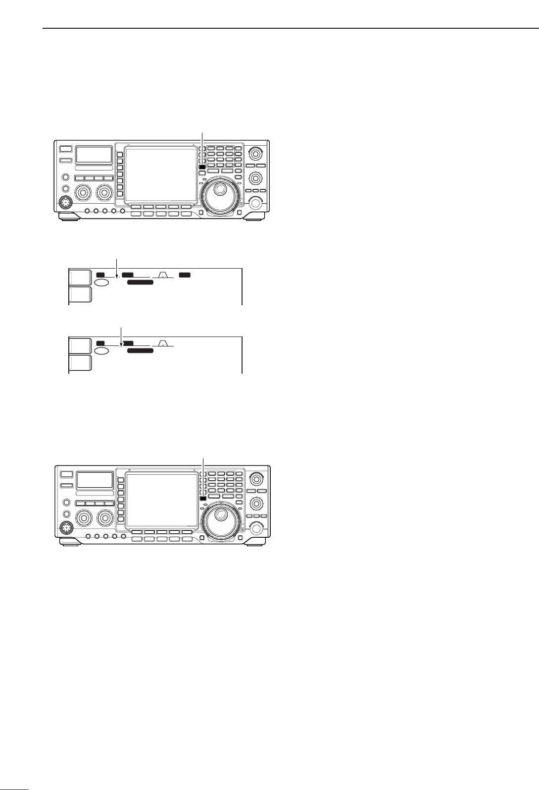
■Selecting VFO/memory mode
➥Push [MAIN/SUB] to select access to the main or
sub readout.
•The sub readout frequency is displayed in outline or
mesh font. The sub readout functions only during split
oeration or dualwatch.
[MAIN/SUB]
■Main/Sub band selection
24
3
BASIC OPERATION
3
The triple band stacking register provides 3 memories
in one band. 3 sets of a frequency and operating mode
on each band are automatically stored when used.
If a band key is pushed once, the frequency and oper-
ating mode last used are called up. When the key is
pushed again, another stored frequency and operating
mode are called up.
This function is convenient when you operate 3 oper-
ating modes on one band. For example, one register
is used for a CW frequency, another for an SSB fre-
quency and the other one for an RTTY frequency.
See the table below for a list of the band available and
the default settings for each band.
Band keys
■Selecting an operating band
BAND REGISTER 1 REGISTER 2 REGISTER 3
1.8 MHz 1.900000 MHz CW 1.910000 MHz CW 1.915000 MHz CW
3.5 MHz 3.550000 MHz LSB 3.560000 MHz LSB 3.580000 MHz LSB
7MHz 7.050000 MHz LSB 7.060000 MHz LSB 7.020000 MHz CW
10 MHz 10.120000 MHz CW 10.130000 MHz CW 10.140000 MHz CW
14 MHz 14.100000 MHz USB 14.200000 MHz USB 14.050000 MHz CW
18 MHz 18.100000 MHz USB 18.130000 MHz USB 18.150000 MHz USB
21 MHz 21.200000 MHz USB 21.300000 MHz USB 21.050000 MHz CW
24 MHz 24.950000 MHz USB 24.980000 MHz USB 24.900000 MHz CW
28 MHz 28.500000 MHz USB 29.500000 MHz USB 28.100000 MHz CW
50 MHz 50.100000 MHz USB 50.200000 MHz USB 51.000000 MHz FM
General 15.000000 MHz USB 15.100000 MHz USB 15.200000 MHz USB
qPush [(14)5], then select a frequency and an oper-
ating mode.
•Frequency and operating mode are memorized in the
first band stacking register.
wPush [(14)5] again, then select another frequency
and operating mode.
•This frequency and operating mode are memorized in
the second band stacking register.
ePush [(14)5] again, then select another frequency
and operating mode.
•This frequency and operating mode are memorized in
the third band stacking register.
•When a fourth frequency and operating mode are se-
lected on a band, the first register set in step q, is over
written.
[Example]: 14 MHz band
1.8 3.5 7
10 14 18
21 24 28
GENE
•50
123
456
789
0
F-INPENT
DDUsing the band stacking registers
25
3BASIC OPERATION
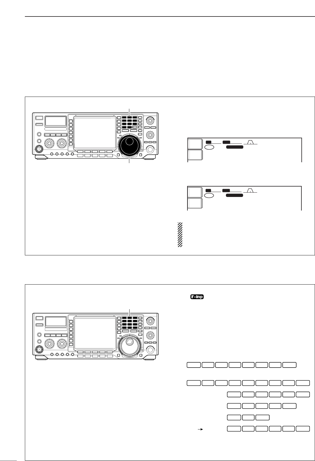
The transceiver has several tuning methods for conve-
nient frequency tuning.
■Frequency setting
DDDirect frequency entry with the keypad
DDTuning with the tuning dial
qPush the desired band key on the keypad 1–3
times.
•3 different frequencies can be selected on each band
with the band key. (See previous page “Using the band
stacking register.”)
wRotate the tuning dial to set the desired frequency.
If the dial lock function is activated, the lock indica-
tor lights, and the tuning dial does not function. In
this case, push [LOCK/SPEECH] to deactivate the
lock function.
METER
Po
ANT
1BW
BW
2.4k
2.4k
SFT
SFT
0
VFO
VFO
FIL2
FIL2
USB
USB
qw:pp
TX
TX
1CW
CW
wq.wot.pp
21.076.50
21.076.50
METER
Po
ANT
1BW
BW
2.4k
2.4k
SFT
SFT
0
VFO
VFO
FIL2
FIL2
USB
USB
qw:pp
TX
TX
1CW
CW
wq.wpp.pp
21.076.50
21.076.50
Band keys
Tuning dial
The transceiver has a keypad for direct frequency
entry as described right.
qPush [(F-INP)ENT].
•“ ” appears.
wInput the desired frequency.
•Push [(GENE)•] to input “• (decimal point)” between the
MHz units and kHz units.
ePush [(F-INP)ENT] to set the input frequency.
•To cancel the input, push [MAIN/SUB] instead of
[(F-INP)ENT].
[EXAMPLE]
Keypad
F-INP
ENT
21.280 21.245
14.025 MHz
1 04 2• 5
08 7• 2 5
ENT7 0• 6
F-INP ENT
2 4• 5
F-INP ENT
18.0725 MHz
1F-INP
706 kHz
F-INP ENT
• 15
5.100 MHz
F-INP ENT
7
7.000 MHz
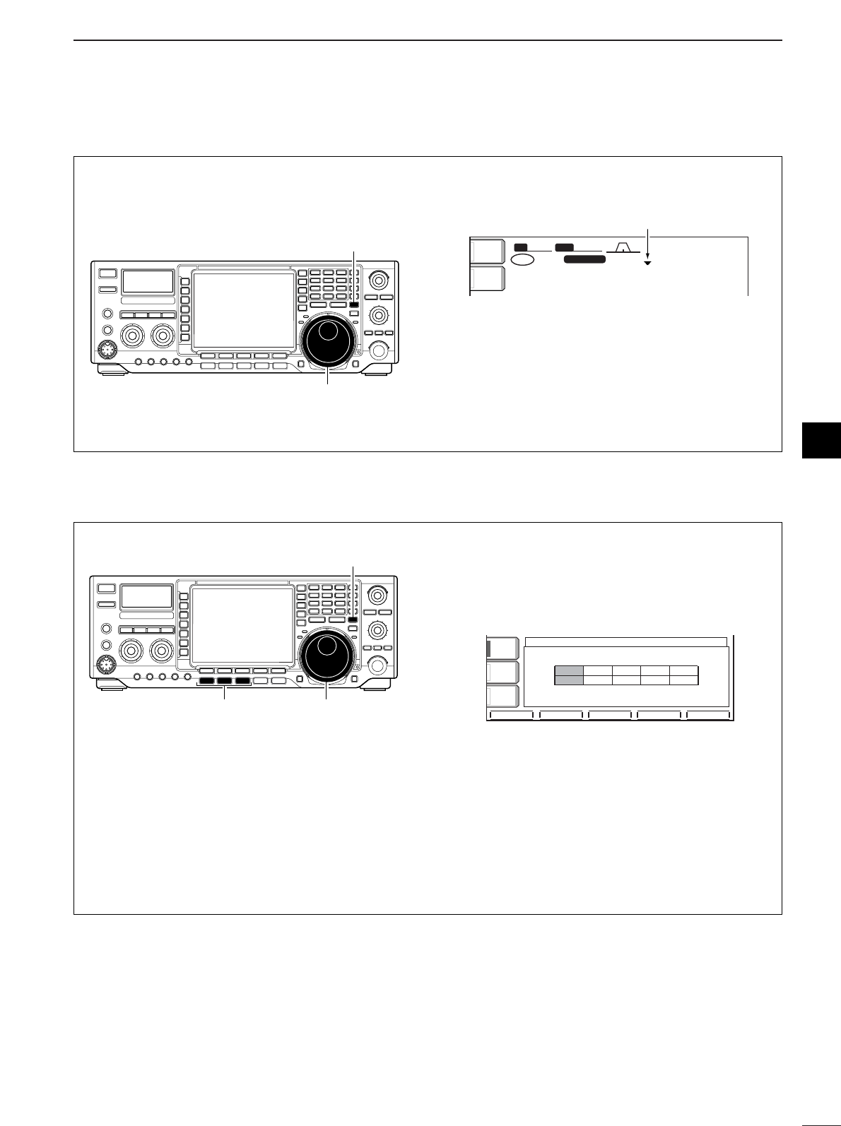
26
3
BASIC OPERATION
3
DDQuick tuning step
The operating frequency can be changed in kHz
steps (0.1, 1, 5, 9, 10, 12.5, 20 or 25 kHz selectable)
for quick tuning.
qPush [TS] momentarily to turn the quick tuning
function ON.
•“Z” appears when the quick tuning function ON.
wRotate the tuning dial to change the frequency in
programmed kHz steps.
ePush [TS] again to turn the quick tuning function
OFF.
•“Z” disappears.
rRotate the tuning dial for normal tuning if desired.
BWBW 2.4k2.4k SFTSFT 0
FIL2FIL2
qw:pp
TXTX
CWCW
qr.qpp.pp
21.076.5021.076.50
VFOVFO
USBUSB
1
METER
Po
ANT
1
Quick tuning indicator
[TS]
Tuning dial
DDSelecting “kHz” step
qPush [TS] momentarily to turn the quick tuning
step ON.
•“Z” appears when the quick tuning function ON.
wPush [TS] for 1 sec. to enter the tuning step set-
ting display.
•Selected tuning steps for all modes appear.
eSelect the desired operating mode.
rRotate the tuning dial to select the desired tuning
step from 0.1, 1, 5, 9, 10, 12.5, 20 or 25 kHz.
•Push [(F-3)DEF] to return to the default setting, if de-
sired.
tRepeat steps eand rto select quick tuning
steps for other modes, if desired.
yPush [EXIT/SET] to exit the setting display.
DEFDEF
TSTS
FMFMAMAM
1010
(kHz)(kHz)
1111
SSBSSB CWCW RTTYRTTY
VOXVOX
OFFOFF
COMPCOMP
OFFOFF
WIDEWIDE
AGCAGC
MIDMID
[TS]
Tuning dial
Mode selection
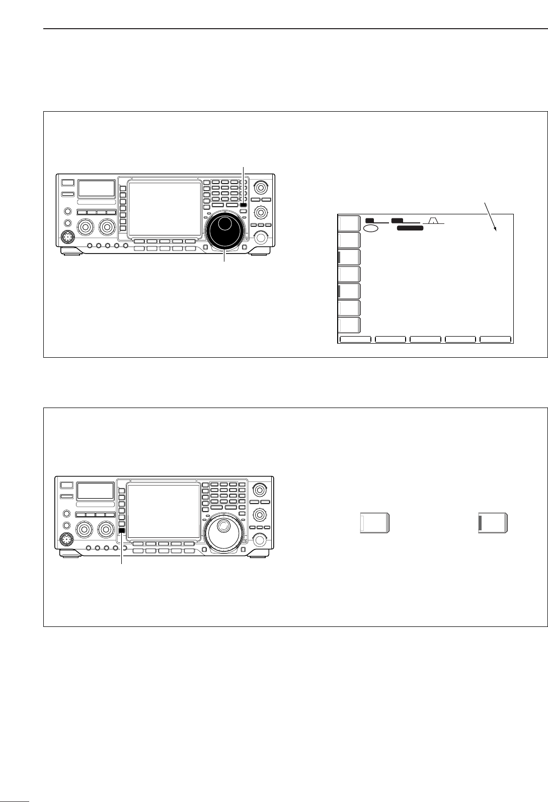
27
3BASIC OPERATION
DDSelecting 1 Hz step
The minimum tuning step of 1 Hz can be used for fine
tuning.
qPush [TS] to turn OFF the quick tuning step.
•“▼” does not appear.
wPush [TS] for 1 sec. to turn the 1 Hz tuning step
ON and OFF.
•RIT and/or ∂TX also functions in 1 Hz tuning step when
used.
SCOPESCOPE VOICEVOICE MEMORYMEMORY SCANSCAN
BWBW 2.4k2.4k SFTSFT 0
FIL2FIL2
USBUSB
qw:pp
1
TXTX
VFOVFO
1
USBUSB
USBUSB
USBUSB
FIL2FIL2
qr.qot.ppp
qr.wpt.ppp
14.100.0014.100.00
14.100.0014.100.00
VFOVFO
ATTATT
0FF0FF
METERMETER
PoPo
P.AMPP.AMP
1
VOXVOX
OFFOFF
COMPCOMP
OFFOFF
WIDEWIDE
AGCAGC
MIDMID
ANTANT
1
1 Hz step indicator
[TS]
Tuning dial
DD1⁄4tuning function (SSB data/CW/RTTY only)
While operating in SSB data/CW/RTTY, the 1⁄4tuning
function is available for critical tuning. Dial rotation is
reduced to 1⁄4of normal when the 1⁄4function is in
use.
➥Push [1/4] to toggle the 1⁄4function ON and OFF.
1/4
OFF
1/4
ON
1⁄4 tuning function OFF 1⁄4 tuning function ON
[1/4]
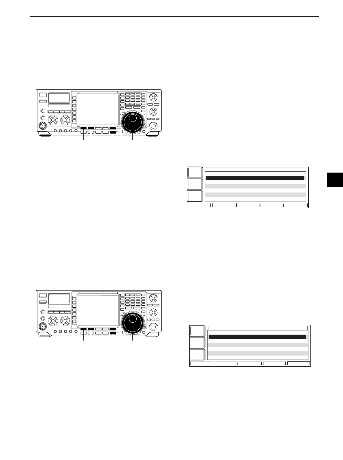
28
3
BASIC OPERATION
3
DDAuto tuning step function
When rotating the tuning dial rapidly, the tuning speed
accelerated automatically as selected.
qPush [EXIT/SET] several times to close a multi-
function screen, if necessary.
wPush [EXIT/SET] for 1 sec. to select the set mode
menu screen.
ePush [(F-5)OTHERS] to enter miscellaneous (oth-
ers) set mode.
rPush [(F-1)Y] or [(F-2)Z] to select “MAIN DIAL
Auto TS.”
tRotate tuning dial to select the desired condition
from high, low and OFF.
•High: Approx. 5 times faster
•Low: Approx. twise faster
•OFF: Auto tuning step is turned OFF
yPush [EXIT/SET] to exit the set mode.
OTHERS OTHERS
SETSET
éèDEFDEF WIDEWIDE
BK-INBK-IN
OFFOFF
1/41/4
OFFOFF
AGCAGC
MIDMID
MemopadNumbers OFF
MAIN DIAL Auto TS HIGH
MIC UP/Down Speed HIGH
Quick RIT/∂TX Clear OFF
SSB/CW Synchronous Tuning OFF
CW Normal Side LSB
External Keypad Auto
Tuning dial
[(F-2)Z] [(F-5)OTHERS]
[(F-1)Y] [EXIT/SET]
DDBand edge warning beep
When selecting a frequency, that lies outsideof a
band’s specified frequency range, a warning beep
sounds.
This function can be turned OFF in set mode, if de-
sired.
qPush [EXIT/SET] several times to close a multi-
function screen, if necessary.
wPush [EXIT/SET] for 1 sec. to select the set mode
menu screen.
ePush [(F-5)OTHERS] to enter miscellaneous (oth-
ers) set mode.
rPush [(F-1)Y] or [(F-2)Z] to select “Beep (Band
edge).”
tRotate tuning dial to turn the band edge warning
beep ON and OFF.
yPush [EXIT/SET] to exit the set mode.
OTHERS OTHERS
SETSET
éèDEFDEF WIDEWIDE
BK-INBK-IN
OFFOFF
1/41/4
OFFOFF
AGCAGC
MIDMID
Beep(Confirmation) ON
Beep(Band Edge) ON
RF/SQL Control RF+SQL
Quick Dualwatch ON
Quick SPLIT ON
FM SPLIT Offset(HF) -0.100MHz
FM SPLIT Offset(50M) -0.100MHz
Tuning dial
[(F-2)Z] [(F-5)OTHERS]
[(F-1)Y] [EXIT/SET]
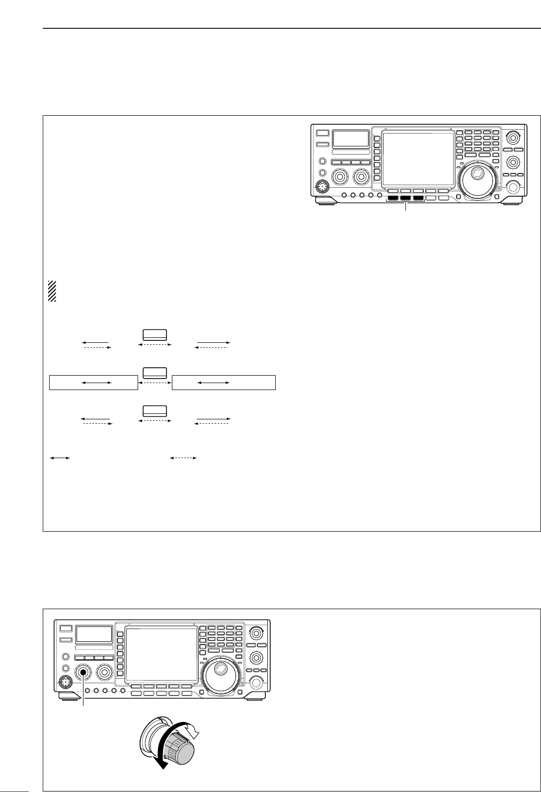
29
3BASIC OPERATION
■Operating mode selection
SSB (LSB/USB), CW, CW-R (CW reverse), RTTY,
RTTY-R (RTTY reverse), AM and FM. Data modes of
SSB, AM and FM are also available in the IC-
756PROIII. Select the desired operation mode as fol-
lows.
To select a mode of operation, push the desired mode
switch momentarily. Push the switch again to toggle
between USB and LSB, CW/CW-R and RTTY/RTTY-
R, AM and FM, if necessary. Push the switch for
1sec. to toggle between CW and CW-R, RTTY and
RTTY-R, or to select data mode, if necessary.
See the diagram below left for the order of selection.
Microphone signals are muted when data mode is
selected.
•Selecting SSB mode
➥Push [SSB] to select USB or LSB.
•USB is selected first when above 10 MHz; or LSB is
selected first when below 10 MHz operation.
(USB is selected when 5 MHz band is selected for the
USA version.)
•After USB or LSB is selected, push [SSB] to toggle be-
tween USB and LSB.
•After USB or LSB is selected, push [SSB] for 1 sec. to
select USB-D or LSB-D mode, respectively.
•Selecting CW/RTTY mode
➥Push [CW/RTTY] to select CW or RTTY.
•After CW or RTTY is selected, push [CW/RTTY] to tog-
gle between CW and RTTY.
•After CW or RTTY is selected, push [CW/RTTY] for
1sec. to toggle between CW and CW reverse, or,
RTTY and RTTY reverse mode, respectively.
•Selecting AM/FM mode
➥Push [AM/FM] to select AM or FM.
•After AM or FM is selected, push [AM/FM] to toggle be-
tween AM and FM.
•After AM or FM is selected, push [AM/FM] for 1 sec. to
select AM-D or FM-D mode, respectively.
Mode selection
SSB
CW/RTTY
AM/FM
USB-D USB
CW-R CW
AM-D AM
Push mode switch
for 1 sec. Push mode switch
momentarily.
LSB LSB-D
RTTY RTTY-R
FM FM-D
■Volume setting
➥Rotate [AF] control clockwise to increase; counter-
clockwise to decrease the audio output level.
•Set a suitable audio level.
Audio output
increases
Audio output
decreases
[AF]
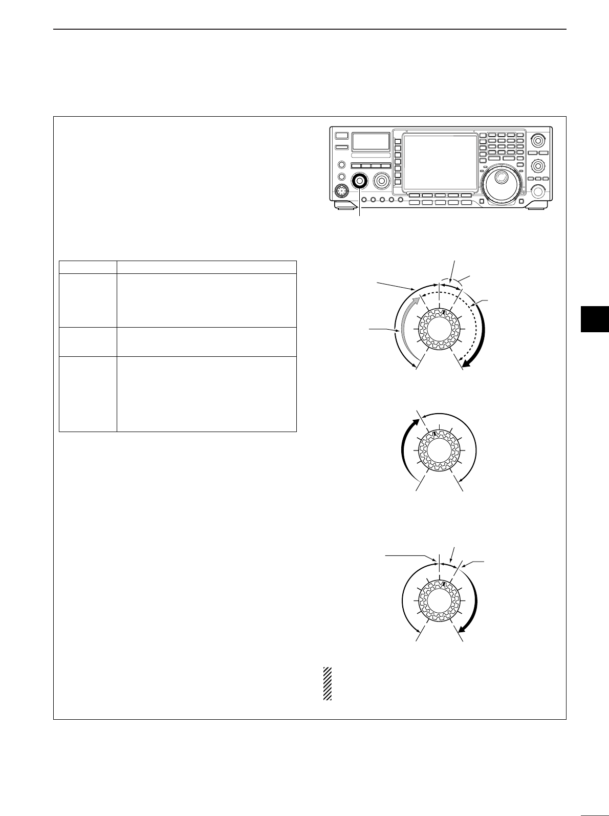
30
3
BASIC OPERATION
3
■Squelch and receive (RF) sensitivity
Adjusts the RF gain and squelch threshold level. The
squelch removes noise output from the speaker
(closed position) when no signal is received.
•The squelch is particularly effective for FM. It is also avail-
able for other modes.
•12 to 1 o’clock position is recommended for any setting of
the [RF/SQL] control.
•The control can be set as ‘Auto’ (RF gain control in SSB,
CW and RTTY; squelch control in AM and FM) or squelch
control (RF gain is fixed at maximum) in set mode as fol-
lows. (p. 98)
Adjusting RF gain (Receive sensitivity)
Normally, [RF/SQL] is set to the 11 o’clock position.
Rotate [RF/SQL] to the 11 o’clock position for maxi-
mum sensitivity.
•Rotating counterclockwise from the maximum position re-
duces sensitivity.
•The S-meter indicates receive sensitivity.
Adjusting squelch (Removing non-signal noise)
Rotate [RF/SQL] clockwise when receiving no signal,
until the noise just disappears.
•[RX] indicator light goes out.
•Rotating [RF/SQL] past the threshold point invokes the S-
meter squelch— this allows you to set a minimum signal
level needed to open the squelch.
•When setting as RF gain/squelch control
•When functioning as RF gain control
(Squelch is fixed open; SSB, CW, RTTY only)
•When functioning as squelch control
(RF gain is fixed at maximum.)
While rotating the RF gain control, noise may be
heard. This comes from the DSP unit and does not
indicate an equipment malfunction.
Squelch is
open.
S-meter
squelch
S-meter squelch
threshold
Noise squelch
threshold
(FM mode)
Shallow Deep
Noise squelch (FM mode)
Minimum RF gain
Adjustable
range
Maximum
RF gain
Recommended level
RF gain
adjustable
range
Maximum
RF gain
S-meter
squelch
Noise squelch (FM mode)
Squelch is
open.
[RF/SQL]
SET MODE OPERATION
RF+SQL
Can be used in all modes.
(default)
Functions as noise squelch or S-meter
squelch in AM and FM modes; S-
meter squelch only in other modes.
SQL Operates as a squelch control.
•RF gain is fixed at maximum sensitivity.
Operates as an RF gain control in
SSB, CW and RTTY modes.
AUTO •Squelch is fixed open.
Operates as a squelch control in AM
and FM modes.
•RF gain is fixed at maximum sensitivity.
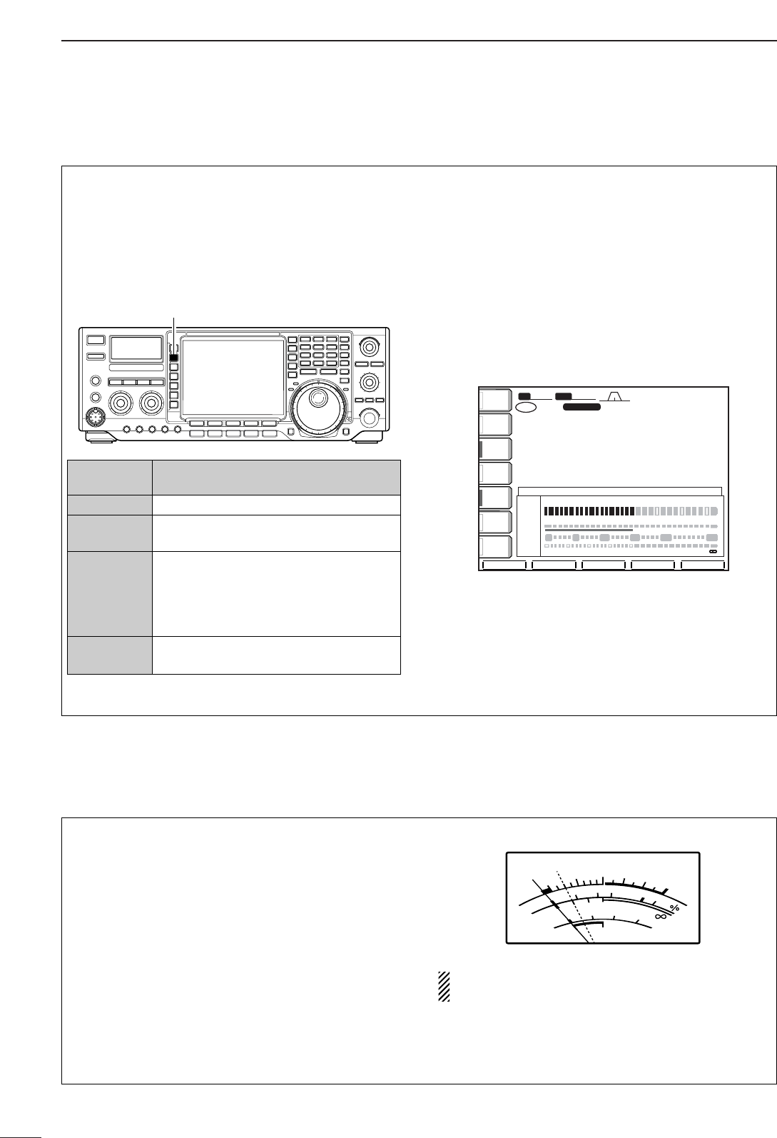
31
3BASIC OPERATION
■Meter function
The transceiver has 4 transmit meter functions for
your convenience. Select the desired meter with the
[METER] switch.
•Analog transmit meter
➥Push [METER] to select RF power (Po), SWR, ALC
or compression level (COMP).
In addition, the transceiver can display the multi-func-
tion digital meter in the LCD display, which displays
all transmit meters simultaneously.
•Multi-function digital meter
qPush [METER] for 1 sec. to turn the multi-function
digital meter ON.
wPush [(F-1)P-HOLD] to toggle the peak level hold
function ON or OFF.
•“P-HOLD” appears on the window title when the peak
level hold function is turned ON.
ePush [METER] for 1 sec. or push [EXIT/SET] to
turn the multi-function digital meter OFF.
P-HOLDP-HOLD
BWBW 2.4k2.4k SFTSFT 0
FIL2FIL2
USBUSB
qw:pp
TXTX
VFOVFO USBUSB
USBUSB
USBUSB
FIL2FIL2
qr.qot.pp
qr.wpt.pp
14.100.0014.100.00
14.100.0014.100.00
1
1
VFOVFO
.1...3...5...7...9..1...3...5...7...9.....+20+20......+40+40......+60dB+60dB
0∑∑∑∑∑∑∑∑∑∑∑∑∑∑∑∑∑∑∑∑∑∑2525∑∑∑∑∑∑∑∑∑∑∑∑∑∑∑∑∑∑∑50 ∑∑∑∑∑∑∑∑∑∑∑∑∑∑∑∑∑∑∑∑∑∑∑∑∑∑∑∑∑∑∑∑∑∑∑∑∑∑ 100%100%
11.51.5 22.52.5 3
S
PoPo
ALCALC
COMPCOMP
SWRSWR
P-HOLDP-HOLD MULTI-FUNCTION METERMULTI-FUNCTION METER
ANTANT
1
COMPCOMP
OFFOFF
WIDEWIDE
METERMETER
PoPo
P.AMPP.AMP
1
AGCAGC
MIDMID
ATTATT
OFFOFF
VOXVOX
OFFOFF
0 5 1010 1515 2020 dB
[METER] switch
DISPLAY MEASUREMENT
INDICATION
Po
Indicates the relative RF output power in %.
SWR Indicates the SWR over the transmission
line.
ALC
Indicates the ALC level. When the meter
movement shows the input signal level ex-
ceeds the allowable level, the ALC limits
the RF power. In such cases, reduce the
[MIC GAIN] control.
COMP Indicates the compression level when the
speech compressor is in use.
■SWR reading
The SWR meter indicates the SWR over the trans-
mission line in all modes.
qPush [TUNER] to turn the antenna tuner OFF.
wPush [METER] several times to select the Po
meter.
ePush [CW/RTTY] once or twice to select RTTY
mode.
rPush [TRANSMIT].
tRotate [RF POWER] clockwise past the 12 o’clock
position for more than 30 W output power (30%).
yPush [METER] once to select the SWR meter as
the transmit meter.
uRead the SWR on the SWR meter.
The built-in antenna tuner matches the transmitter
to the antenna when the SWR is lower than 3 : 1.
SWR
S
COMP
ALC
Po
010
10
25 50 100
20
101.5 23
159+20 +40 +60dB
dB
SWR meter
Less than 1.5:1
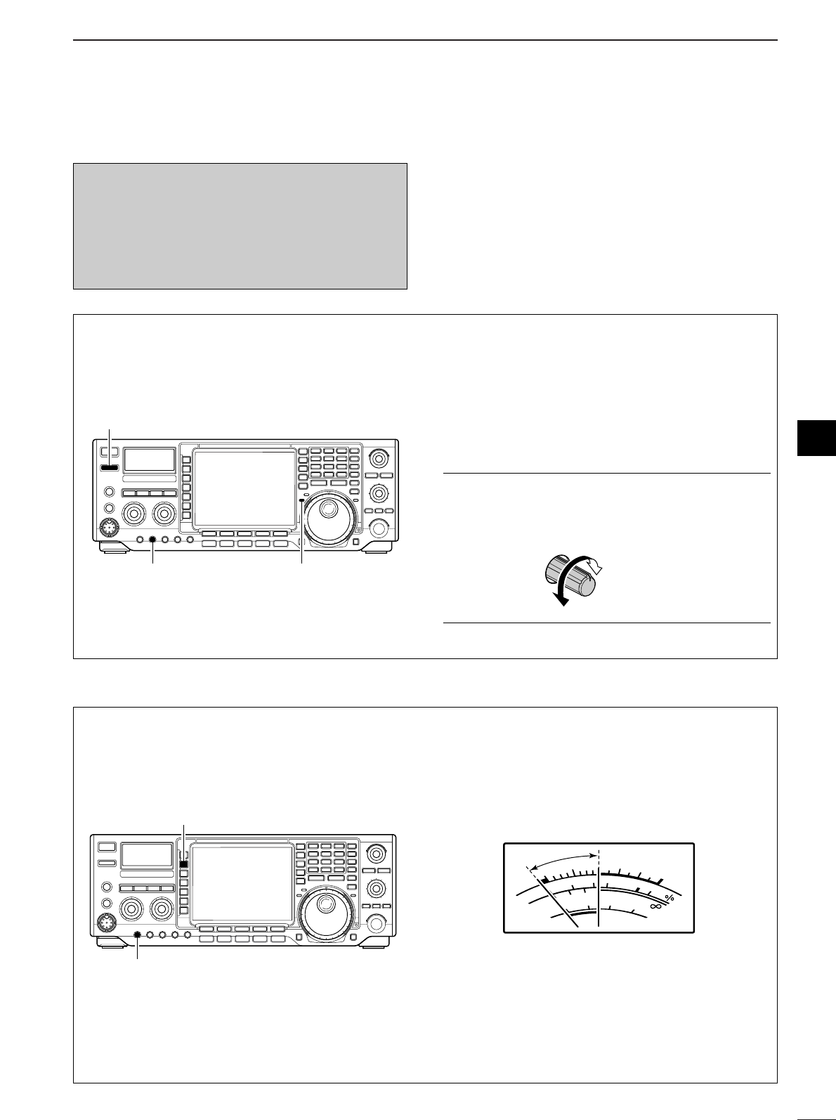
32
3
BASIC OPERATION
3
■Basic transmit operation
DDTransmitting
Before transmitting, monitor your selected operating
frequency to make sure transmitting won’t cause in-
terference to other stations on the same frequency.
qPush [TRANSMIT] or [PTT] (microphone) to trans-
mit.
•The main band’s [TX] indicator lights red.
•When the split operation is activated, the sub band’s
[TX] indicator lights.
wPush [TRANSMIT] again or release [PTT] (micro-
phone) to return to receive.
✔
Adjusting the transmit output power
➥Rotate [RF PWR].
•Adjustable range: 5 W to 100 W
(AM mode: 5 W to 40 W)
Increases
max. 100 W
(40 W for AM)
Decreases
min. 5 W
[TRANSMIT]
[TX] indicator[RF POWER]
DDMicrophone gain adjustment
Before transmitting, monitor your selected operating
frequency to make sure transmitting won’t cause in-
terference to other stations on the same frequency.
qPush [METER] to select the ALC meter.
wPush [PTT] (microphone) to transmit.
•Talk into the microphone at your normal voice level.
eWhile talking into the microphone, rotate [MIC
GAIN] so that the ALC meter reading doesn’t go
outside the ALC zone.
rRelease [PTT] (microphone) to return to receive.
In addition, the transceiver can display the multi-func-
tion digital meter in the LCD display, which displays
all transmit meters simultaneously.
SWR
S
COMP
ALC
Po
010
10
25 50 100
20
101.5 23
159+20 +40 +60dB
dB
ALC zone
[METER]
[MIC GAIN]
Before transmitting, monitor your selected oper-
ating frequency to make sure transmitting won’t
cause interference to other stations on the same
frequency. It’s good Amateur practice to listen
first, and then, even if nothing is heard, ask “is
the frequency in use” once or twice, before you
being operating on that frequency.

DConvenient functions for receive
4
33
RECEIVE AND TRANSMIT
■Operating SSB qPush a band key to select the desired band.
wPush [SSB] to select LSB or USB.
•“LSB” or “USB” appears.
•Below 10 MHz LSB is automatically selected; above
10 MHz USB is automatically selected.
eRotate the tuning dial to tune a desired signal.
•The S-meter indicates received signal strength when
signal is received.
rRotate [AF] to set audio to a comfortable listening
level.
tPush [TRANSMIT] or [PTT] (microphone) to trans-
mit.
•The TX indicator lights red.
ySpeak into the microphone at your normal voice
level.
•Adjust the microphone gain with [MIC] at this step, if
necessary.
uPush [TRANSMIT] or release [PTT] (microphone) to
return to receive.
[TRANSMIT]
[SSB]
[AF] [MIC GAIN] Tuning dial
[TX] indicator [RX] indicator Band keys
•Preamp (p. 57)
➥Push [P.AMP] several times to set the preamp
OFF, preamp 1 ON or preamp 2 ON.
•“P.AMP1” or “P.AMP2” appears when the preamp 1 or
preamp 2 is set to ON, respectively. (depending on op-
erating frequency band)
•Attenuator (p. 57)
➥Push [ATT] several times to set the attenuator in
6dB steps.
•“ATT” and attenuation level appear when the attenua-
tor is set to ON.
•Noise blanker (p. 62)
➥Push [NB] switch to turn the noise blanker ON
and OFF.
•Noise blanker indicator (in [NB] switch) lights when the
noise blanker is set to ON.
➥Push [NB] for 1 sec. to enter the noise blanker
level set mode, then rotate tuning dial to adjust
the threshold level.
•Twin PBT (passband tuning) (p. 60)
➥Rotate [TWIN PBT] controls (inner/outer).
•Push [PBT CLR] to clear the settings.
•Noise reduction (p. 64)
➥Push [NR] switch to turn the noise reduction ON
and OFF.
•Rotate [NR] control to adjust the noise reduction level.
•Noise reduction indicator (in [NR] switch) lights when
the noise reduction is set to ON.
•Notch filter (p. 64)
➥Push [NOTCH] switch to turn the auto or manual
notch function ON and OFF.
•Rotate [NOTCH] control to set the attenuating fre-
quency for manual notch operation.
•Notch indicator (in [NOTCH] switch) lights when either
the auto or manual notch is set to ON.
•AGC (auto gain control) (p. 59)
➥Push [AGC] switch several times to select
AGC FAST, AGC MID or AGC SLOW.
➥Push [AGC] for 1 sec. to enter the AGC set mode.
•Rotate tuning dial to adjust the time constant.

34
4
RECEIVE AND TRANSMIT
DConvenient functions for transmit
•Speech compressor (p. 67)
➥Push [COMP] to turn the speech compressor ON
and OFF.
•Pushing [COMP] for 1 sec. to select the compression
bandwidth from wide, middle and narrow.
•Transmit quality monitor (p. 69)
➥Push [MONITOR] to turn the monitor function ON
and OFF.
•Monitor indicator (in [MONI] switch) lights when the
monitor function is set to ON.
➥Push [EXIT/SET] for 1 sec. then [(F-1)LEVEL] to
enter level set mode. Select the monitor level item
with [(F-1)Y]/[(F-2)Z] then rotate the tuning dial
to adjust the monitor gain.
•VOX (voice operated transmit) (p. 65)
➥Push [VOX] to turn the VOX function ON and
OFF.
•“VOX ON” appears when the VOX function is set to
ON.
•Audio tone control (p. 93)
➥Push [EXIT/SET] for 1 sec. then [(F-1)LEVEL] to
enter level set mode. Select an item with [(F-
1)Y]/[(F-2)Z] then rotate the tuning dial to adjust
the audio tone.
DDAbout 5 MHz band operation (USA version only)
Operation on the 5 MHz band is allowed on 5 discrete
frequencies and must adhere to the following:
•USB mode
•Maximum of 50 watts ERP (Effective Radiated Power)
•2.8 kHz bandwidth
It is the operator’s responsibility to set all controls so
that the transmission in this band meets the stringent
conditions under which we may use these frequencies.
NOTE: We recommend that you store these fre-
quencies, mode and filter settings into the memory
channel for easy recall.
*The channel center frequencies that are specified
by the FCC, show the center frequency of their
passband. However, the IC-756PROIII displays
carrier point frequency, so set 1.5 kHz below from
FCC channel center frequency.
4
IC-756PROIII Tuning FCC Channel
Frequency* Center Frequency*
5.33050 MHz 5.33200 MHz
5.34650 MHz 5.34800 MHz
5.36650 MHz 5.36800 MHz
5.37150 MHz 5.37300 MHz
5.40350 MHz 5.40500 MHz
To assist you in operating the 5 MHz band correctly
within the rules specified by the FCC, transmission
is impossible on any 5 MHz band frequency other
than the 5 frequencies indicated in the table above.

35
4RECEIVE AND TRANSMIT
DConvenient functions for receive
■Operating CW qPush a band key to select the desired band.
wPush [CW/RTTY] to select CW.
•After CW mode is selected, push [CW/RTTY] for 1 sec.
to toggle between CW and CW-R modes.
•“CW” or “CW-R” appears.
eRotate the tuning dial to simultaneously tune a de-
sired signal and its side tone.
•The S-meter indicates received signal strength when
signal is received.
rRotate [AF] to set audio to a comfortable listening
level.
tPush [TRANSMIT] to transmit.
•The TX indicator lights red.
yUse the electric keyer or paddle to key your CW sig-
nals.
•The power meter indicates transmittted CW output
power.
uAdjust CW speed with [KEY SPEED].
•Adjustable within 6-60 WPM.
iPush [TRANSMIT] to return to receive.
[CW/RTTY][AF] [KEY SPEED] Tuning dial
[TRANSMIT] [TX] indicator [RX] indicator Band keys
•Preamp (p. 57)
➥Push [P.AMP] several times to set the preamp
OFF, preamp 1 ON or preamp 2 ON.
•“P.AMP1” or “P.AMP2” appears when the preamp 1 or
preamp 2 is set to ON, respectively. (depending on op-
erating frequency band)
•Attenuator (p. 57)
➥Push [ATT] several times to set the attenuator in
6dB steps.
•“ATT” and attenuation level appear when the attenua-
tor is set to ON.
•Noise blanker (p. 62)
➥Push [NB] switch to turn the noise blanker ON
and OFF.
•Noise blanker indicator (in [NB] switch) lights when the
noise blanker is set to ON.
➥Push [NB] for 1 sec. to enter the noise blanker
level set mode, then rotate tuning dial to adjust
the threshold level.
•Twin PBT (passband tuning) (p. 60)
➥Rotate [TWIN PBT] controls (inner/outer).
•Push [PBT CLR] to clear the settings.
•Noise reduction (p. 64)
➥Push [NR] switch to turn the noise reduction ON
and OFF.
•Rotate [NR] control to adjust the noise reduction level.
•Noise reduction indicator (in [NR] switch) lights when
the noise reduction is set to ON.
•Notch filter (p. 64)
➥Push [NOTCH] switch to turn the manual notch
function ON and OFF.
•Rotate [NOTCH] control to set the attenuating fre-
quency for manual notch operation.
•Notch indicator (in [NOTCH] switch) lights when the
manual notch is set to ON.
•AGC (auto gain control) (p. 59)
➥Push [AGC] switch several times to select
AGC FAST, AGC MID or AGC SLOW.
➥Push [AGC] for 1 sec. to enter the AGC set mode.
•Rotate tuning dial to adjust the time constant.
•1⁄4function (p. 27)
➥Push [1/4] to turn the 1⁄4function ON and OFF.
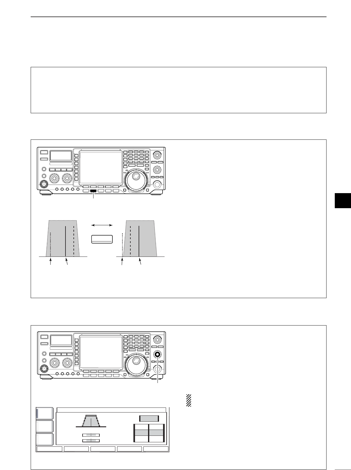
36
4
RECEIVE AND TRANSMIT
DConvenient functions for transmit
•Break-in function (p. 66)
➥Push [BK-IN] several times to select the break-in
OFF, semi break-in and full break-in.
•“BK-IN SEMI” or “BK-IN FULL” appears when the
semi break-in or full break-in function is set to ON, re-
spectively.
DDAbout CW reverse mode
CW-R (CW Reverse) mode receives CW signals with
a reverse side CW carrier point like that of LSB and
USB modes.
Use when interfering signals are near a desired signal
and you want to change the interference tone.
qPush [CW/RTTY] once or twice to select CW
mode.
wPush [CW/RTTY] for 1 sec. to select CW or CW-R
mode.
•Check the interfering tone.
Push
for 1 sec.
BFO
CW-R mode (USB side)
BFO
Desired signal
CW mode (LSB side)
Interference Desired signalInterference
CW/RTTY
[CW/RTTY]
DDAbout CW pitch control
The received CW audio pitch and monitored CW
audio can be adjusted to suit your preference (300 to
900 Hz in 25 Hz steps) without changing the operat-
ing frequency.
➥Rotate [CW PITCH] to suit your preference.
•Adjustable within 300 to 900 Hz in 25 Hz steps.
The filter set mode screen graphically displays the
CW pitch operations. (See at left.)
FILTER
FILTER
CW
CW
FI
FI
L 1
FI
FI
L 2
FI
FI
L 3
1.2k
1.2k
500
500
250
250
PBT2
PBT2
PBT1
PBT1
450 700 950
450 700 950
BK-IN
BK-IN
OFF
OFF
AGC
AGC
MID
MID
1/4
1/4
OFF
OFF
BW
BW
DEF
DEF
[CW PITCH]
4
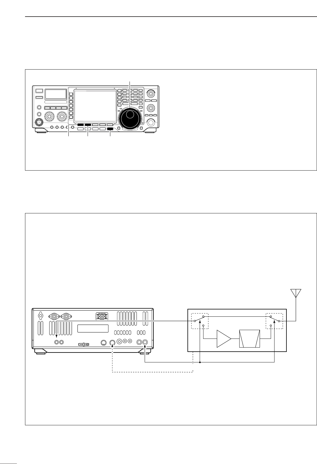
37
4RECEIVE AND TRANSMIT
DDAbout 137 kHz band operation (Europe, UK, Italy, Spain, France versions only)
137 kHz band, within 135.7 kHz to 137.8 kHz range,
operation in CW mode is optionally available with the
IC-756PROIII.
The RF signal from [XVERT] is used for the 137 kHz
band operation, and an external amplifier unit is nec-
essary.
See the connection diagram below for reference.
•Connection diagram for 137 kHz band operation
DDCW side tone function
When the transceiver is in the receive condition (and
the break-in function is OFF— p. 66) you can listen to
the tone of your CW signal without actually transmit-
ting.
This allows you to match your transmit signal exactly
to another station’s. This also convenient for CW
practice.
➥Push [EXIT/SET] for 1 sec. then [(F-1)LEVEL] to
enter level set mode. Select an item with [(F-
1)Y]/[(F-2)Z] then rotate the tuning dial to adjust
the side tone level.
Tuning dial
[EXIT/SET]
[(F-1)Y] [(F-2)Z]
to [ACC(2)] pin 6*
PA BPF
or
LPF
Power amplifier with T/R switching unit
for 137 kHz
to [XVERT]
*Transverter ON/OFF control signal related to the power amplifier
unit main power, if desired.
• ON: 2–13.8 V DC input (more than 10 kΩ impedance)
• OFF: Less than 2 V DC
to [SEND] (for transmit/receive control)
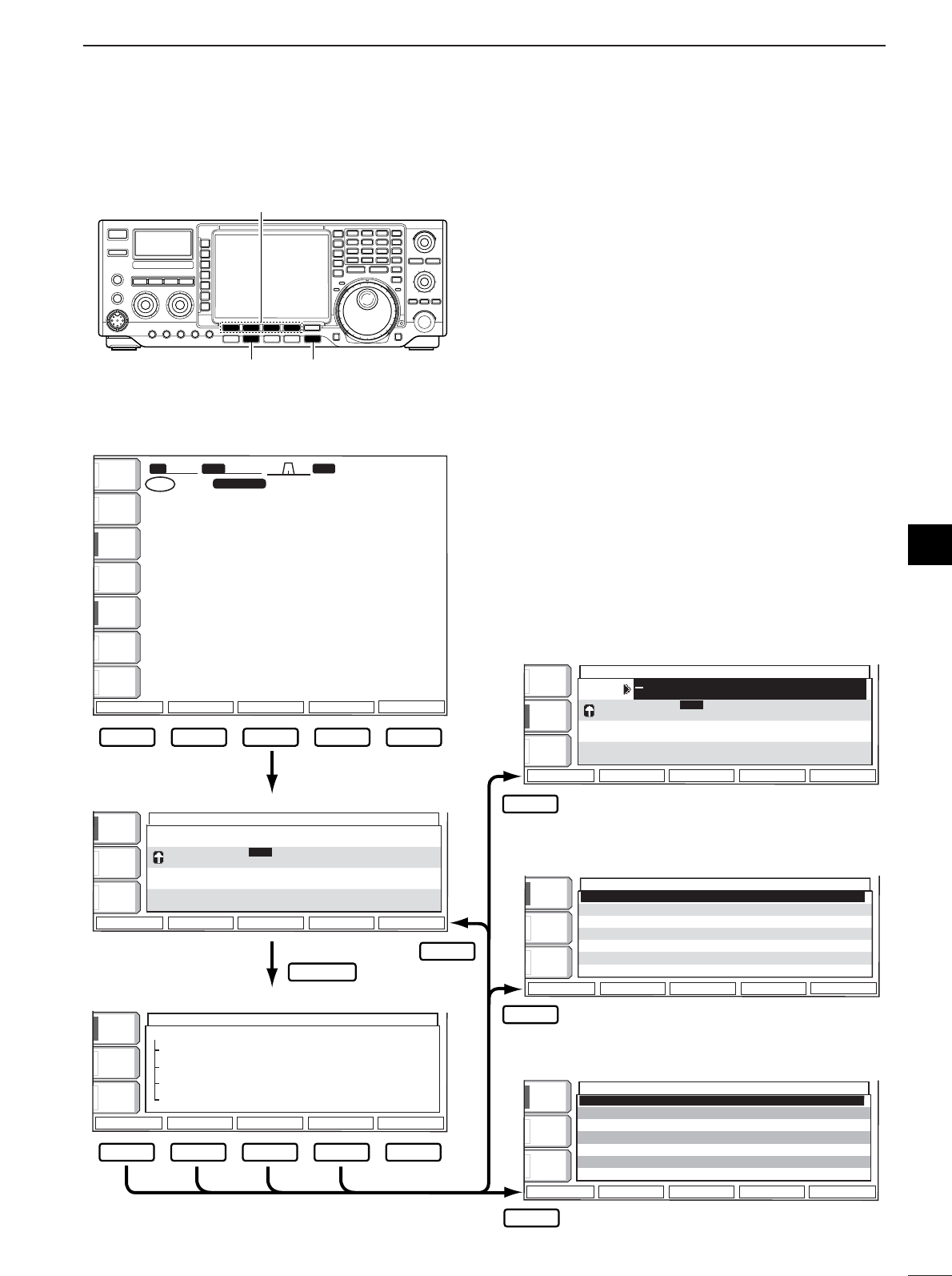
38
4
RECEIVE AND TRANSMIT
4
■Electronic CW keyer
The IC-756PROIII has a number of convenient func-
tions for the electronic keyer that can be accessed
from the memory keyer menu.
qPush [EXIT/SET] several times, if necessary.
wPush [CW/RTTY] to select CW mode.
ePush [(F-3)KEYER] then [EXIT/SET] to select
memory keyer menu screen.
rPush one of the multi-function keys ([F-1] to [F-4]
to select the desired menu. See the diagram
below.
•Push [EXIT/SET] to return to the previous indication.
[CW/RTTY] [EXIT/SET]
[(F-1)]–[(F-4)]
F-1 F-2 F-3 F-4 F-5
BK-INBK-IN
OFFOFF
1/41/4
OFFOFF
AGCAGC
MIDMID
MEMORY KEYERMEMORY KEYER
MEMORY KEYER MENUMEMORY KEYER MENU
SEND Max.55 Characters SEND Max.55 Characters ◊ 4ch 4ch
EDIT Memory Editor EDIT Memory Editor
001 001 Style Contest Number 001 001 Style Contest Number
CW KEY Memo-key,Elec-key,CW Wave Form Set CW KEY Memo-key,Elec-key,CW Wave Form Set
¡Memory keyer menu screen
BK-INBK-IN
OFFOFF
1/41/4
OFFOFF
AGCAGC
MIDMID
MEMORY KEYERMEMORY KEYER
CQ TEST CQ TEST DE ICOM ICOMCQ TEST CQ TEST DE ICOM ICOM
TESTTEST
QRZ?QRZ?
M1M1
M2M2
M3M3
M4M4
CFM TUCFM TU
UR 5NNUR 5NN001001 BK BK
¡Memory keyer send screen
ABCABC
123123
MEMORY KEYERMEMORY KEYER
CQ TEST CQ TEST DE ICOM ICOMCQ TEST CQ TEST DE ICOM ICOM
TESTTEST
QRZ?QRZ?
M1M1
M2M2
M3M3
M4M4
CFM TUCFM TU
UR 5NNUR 5NN001001 BK BK
ABCABC
¡Memory keyer edit screen
KEYER 001KEYER 001
Number StyleNumber Style NormalNormal
CounCount Up Triggert Up Trigger M2M2
Present NumberPresent Number 001001
BK-INBK-IN
OFFOFF
1/41/4
OFFOFF
AGCAGC
MIDMID
¡Contest number set mode
BK-INBK-IN
OFFOFF
1/41/4
OFFOFF
AGCAGC
MIDMID
KEYER CW-KEYKEYER CW-KEY
Keyer Repeat TimeKeyer Repeat Time 2s2s
Dot/Dash RatioDot/Dash Ratio 1:1:3.01:1:3.0
Rise TimeRise Time 4ms4ms
Paddle PolarityPaddle Polarity NormalNormal
Keyer TypeKeyer Type ELEC-KEYELEC-KEY
MIC Up/Down KeyerMIC Up/Down Keyer OFFOFF
¡Keyer set mode screen
F-1 F-2
F-1
F-2
F-3
F-3
F-4
F-4
F-5
21. 085. 0021. 085. 00
1
ANTANT
1
METERMETER
PoPo
P.AMPP.AMP
1
ATTATT
0FF0FF
BK-INBK-IN
OFFOFF
1/41/4
OFFOFF
BWBW 500500 SFTSFT
VFOVFO FIL2FIL2
CWCW
qw:pp
AGCAGC
MIDMID
1
21. 085. 0021. 085. 00
TXTX
VFOVFO USBUSB FIL2FIL2
CW
CW
CW
CW
BPF
EXIT/SET
SCOPESCOPE VOICEVOICE
KEYER
MEMORYMEMORY SCANSCAN
M1M1 M2M2 M3M3 M4M4 -1-1
éèDEFDEF
éèDEFDEF
çåDELDEL SPACESPACE M1..M4M1..M4
SENDSEND EDITEDIT 001001 CW KEYCW KEY
0
qr.qpp.pp
qr.qpp.pp
12:0012:00
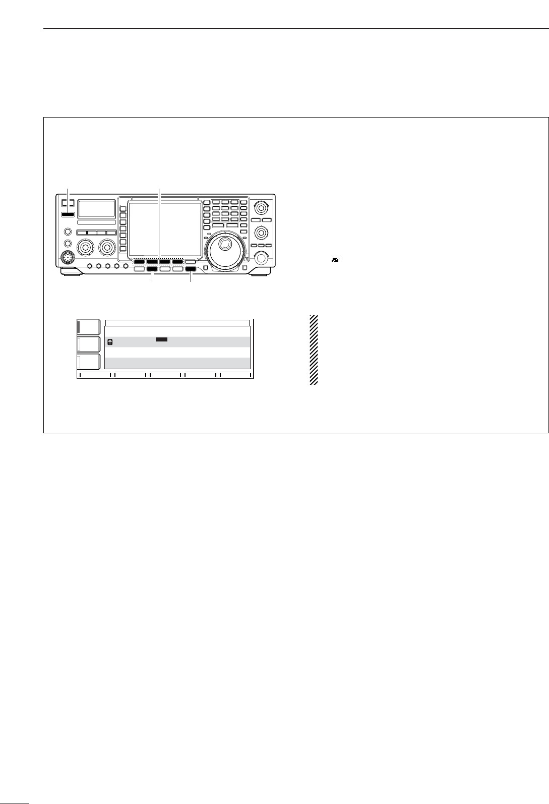
39
4RECEIVE AND TRANSMIT
Pre-set characters can be sent using the keyer send
menu. Contents of the memory keyer are set using
the edit menu.
•Transmitting
qPush [EXIT/SET] several times, if necessary.
wPush [CW/RTTY] to select CW mode.
ePush [(F-3)KEYER] to select the memory keyer
screen.
rPush [TRANSMIT] to set the transceiver to trans-
mit, or set the break-in function ON (p.60).
tPush [(F-1)M1] – [(F-4)M4] momentarily to trans-
mit the contents one time; push these keys for 1
sec. to transmit the contents repeatedly.
•“M1”–“M4” are highlighted while transmitting.
•“ ” appears while transmitting repeatedly.
•
Set the repeat interval of the memory keyer to 1, 2, 3,
10 or 30 sec. See the previous page for keyer set mode.
•To count down the contact number, push [(F-5)–1].
For your information
When an external keypad is connected to the pin 3
and pin 7 of the [MIC] connecter, the programmed
contents, M1–M4, can be transmitted without open-
ing the memory keyer screen.
See page 103 for details.
yPush [EXIT/SET] twice to exit the memory keyer
screen.
MEMORY KEYER
MEMORY KEYER
M1
M1
M2
M2
M3
M3
M4
M4
CQ
CQ
TEST
TEST
CQ
CQ
TEST
TEST
DE
DE
ICOM
ICOM
ICOM
ICOM
TEST
TEST
QRZ?
QRZ?
CFM
CFM
TU
TU
UR
UR
5NN
5NN
001
001
BK
BK
AGC
AGC
MID
MID
1/4
1/4
OFF
OFF
BK-IN
BK-IN
OFF
OFF
M1
M1
M2
M2
M3
M3
M4
M4
-1
-1
[CW/RTTY]
[TRANSMIT]
[EXIT/SET]
[(F-1)M1]–[(F-4)M4]
DDMemory keyer send screen
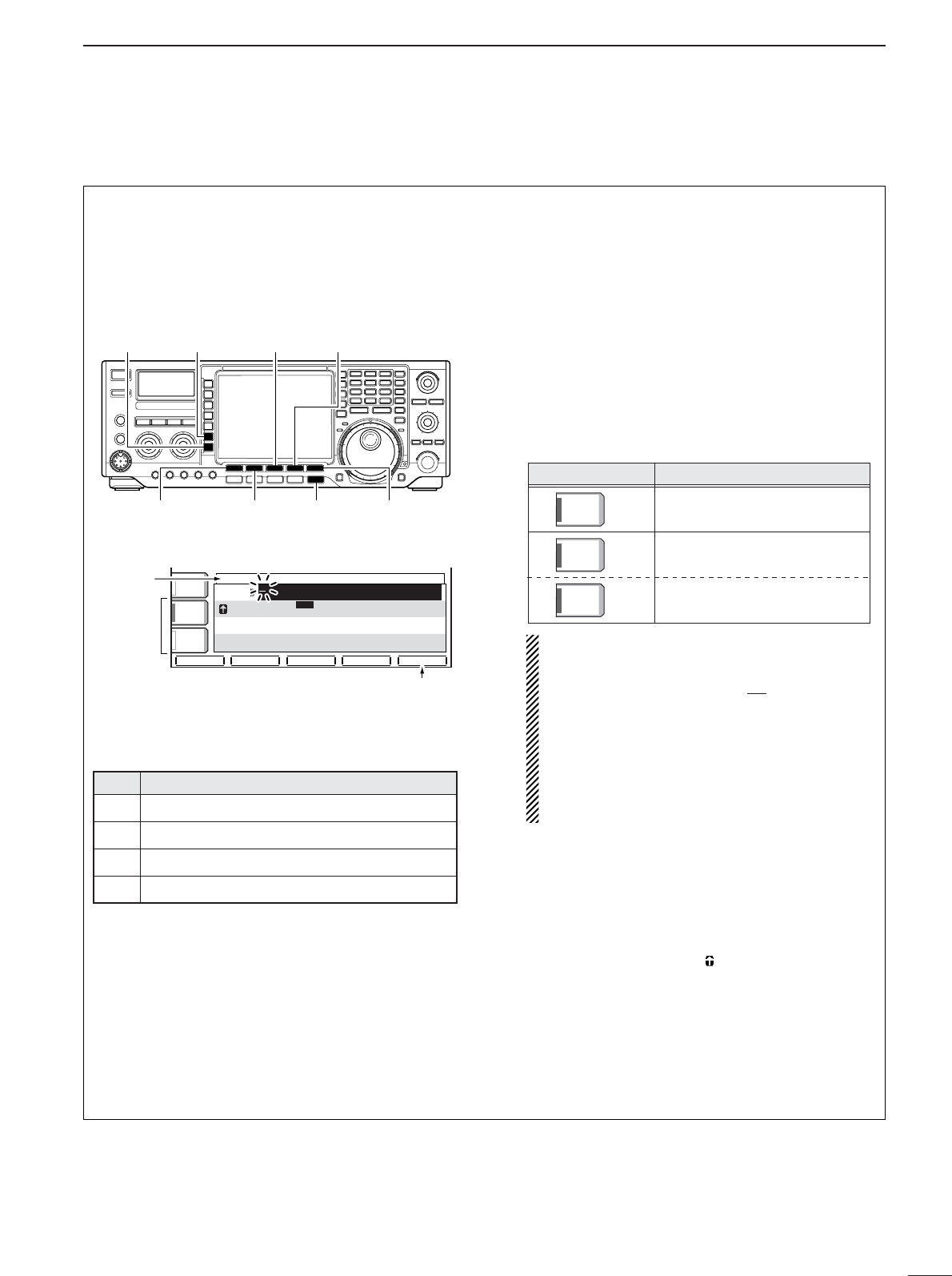
40
4
RECEIVE AND TRANSMIT
The contents of the momory keyer memories can be
set using the memory keyer edit menu. The memory
keyer can memorize and re-transmit 4 CW key codes
for often-used CW sentences, contest number, etc.
Total capacity of the memory keyer is 70 characters
per memory channel.
• Pre-programmed contents
•Programming contents
qPush [EXIT/SET] several times, if necessary.
wPush [CW/RTTY] to select CW mode.
ePush [(F-3)KEYER] then [EXIT/SET] to select
keyer set mode.
rPush [(F-2)EDIT] to enter the keyer edit screen.
tPush [(F-5)M1..M4] several times to select the de-
sired keyer memory channel.
ySelect the desired character group by pushing the
character group keys ([ABC], [123] or [etc]) several
times.
•[etc] appears when [123] is pushed when “123” char-
acter group is selected.
•Selectabel characters (with the tuning dial);
NOTE:
“^” is used to transmit a following word with no
space such as
AR
. Put “^” before a text string
such as ^AR, and the string “ ” is sent with no
space.
“✱” is used to insert the CW contest number.
The contest number automatically increments
by 1. This function is only available for one
memory keyer channel at a time. Memory keyer
channel M2 used “✱” by default.
uSelect the desired character by rotating the tuning
dial or by pushing the band key for number input.
•Push [(F-1)Ω] or [(F-2)≈] for cursor movement.
•Push [(F-3)DEL] to delete the selected character.
•Push [(F-4)SPACE] to input a space.
•“*” is for contact numbers and can be input for the
count up trigger channel (“ ” appears).
iRepeat step uuntil the desired contents are input.
oPush [(F-5)M1..M4] to select the next memory
channel and repeat step ufor character input, if
desired.
!0 Push [EXIT/SET] twice to exit the keyer set mode.
AR
Key selection
ABC
ABC
Editable characters
A to Z (capital leters)
123
123
0 to 9 (numbers)
/ ? ^ . , @ ✽
etc
etc
CH Contents
CQ TEST CQ TEST DE ICOM ICOM TEST
UR 5NN✽ BK
CFM TU
M1
M2
M3
QRZ?
M4
çåDEL
DEL
SPACE
SPACE
M1..M4
M1..M4
KEYER EDIT
KEYER EDIT
M1
M1
M2
M2
M3
M3
M4
M4
CQ
CQ
TEST
TEST
CQ
CQ
TEST
TEST
DE
DE
ICOM
ICOM
ICOM
ICOM
TEST
TEST
QRZ?
QRZ?
CFM
CFM
TU
TU
UR
UR
5NN
5NN
001
001
BK
BK
ABC
ABC
ABC
ABC
123
123
Character
group
keys
Selected
character
Memory ch
select
[(F-2)≈][(F-1)Ω]
[123]/[etc] [ABC]
[EXIT/SET] [(F-5)M1..M4]
[(F-3)DEL] [(F-4)SPACE]
DDEditing a memory keyer
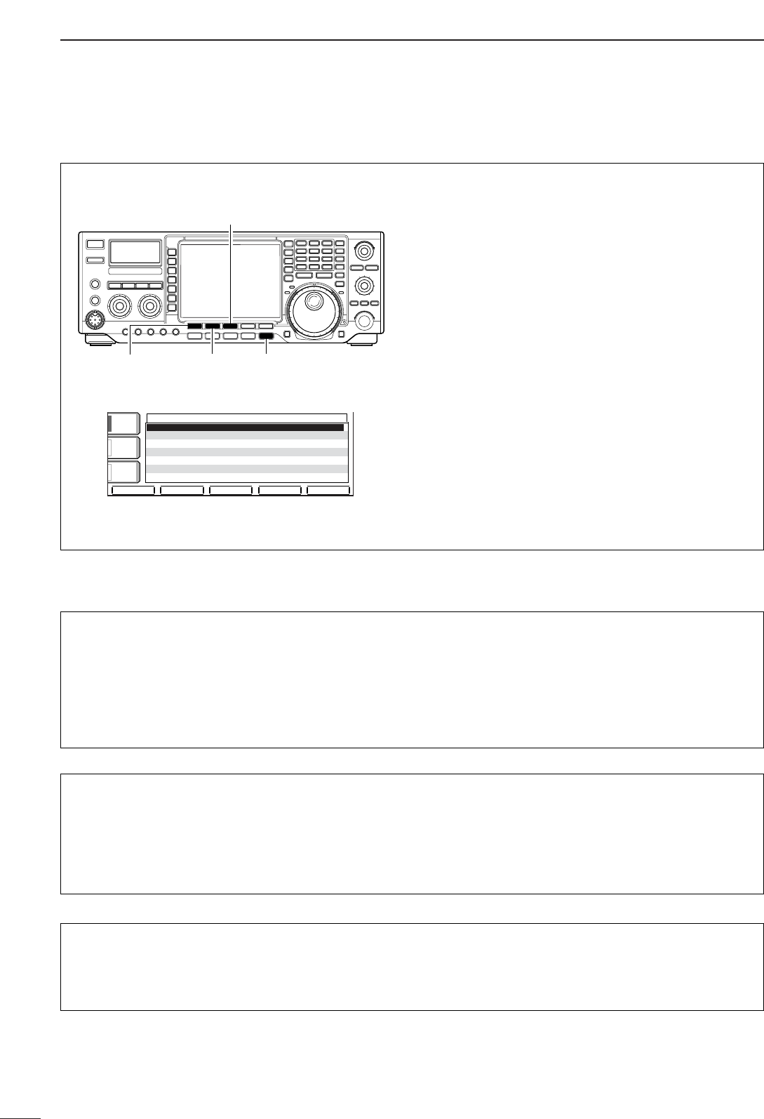
41
4RECEIVE AND TRANSMIT
This menu is used to set the contest (serial) number
and count up trigger, etc. •Setting the contact (serial) number
Contact number can be automatically transmitted
from one of the memory keyer channels. The Morse
cut numbers can be used as the contact numbers.
The maximum number for contact numbers is 9999.
qPush [EXIT/SET] several times, if necessary.
wPush [CW/RTTY] to select CW mode.
ePush [(F-3)KEYER] then [EXIT/SET] to select
keyer set mode.
rPush [(F-3)001] to select contest number set
mode.
t
Push [(F-1)∫] or [(F-2)√] to select the desired set
item.
•Push [(F-3)DEF] for 1 sec. to select the default condi-
tion or value.
yPush [EXIT/SET] twice to exit the keyer set mode.
KEYER 001KEYER 001
NumberNumberStyleStyle NormalNormal
CounCountUPUPTriggerTrigger M2M2
PresentPresentNumberNumber 001001
AGCAGC
MIDMID
1/41/4
OFFOFF
BK-INBK-IN
OFFOFF
éèDEFDEF
[(F-2)√][(F-1)∫] [EXIT/SET]
[(F-3)DEL]
DDContest number set mode
Count Up Trigger (Count up trigger)
This selects which of the three memory slots will have
the contest serial number exchange. The count up
trigger allows the serial number automatically incre-
mented after each complete serial number exchange
is sent.
•M1, M2, M3 and M4 can be set. (default: M2)
Number Style (Number style)
This item sets the numbering system used for contest
(serial) numbers— normal or morse cut numbers.
Normal : Does not use morse cut number
(default)
190➜ANO : Sets 1 as A, 9 as N and 0 as O.
190➜ANT : Sets 1 as A, 9 as N and 0 as T.
90➜NT : Sets 9 as N and 0 as O.
90➜NT : Sets 9 as N and 0 as T.
Present Number (Present number)
This item shows the current number for the count up
trigger channel set above.
•Rotate the tuning dial to change the number, or push
[(F-3)001CLR] for 1sec. to reset the current number
to 001.
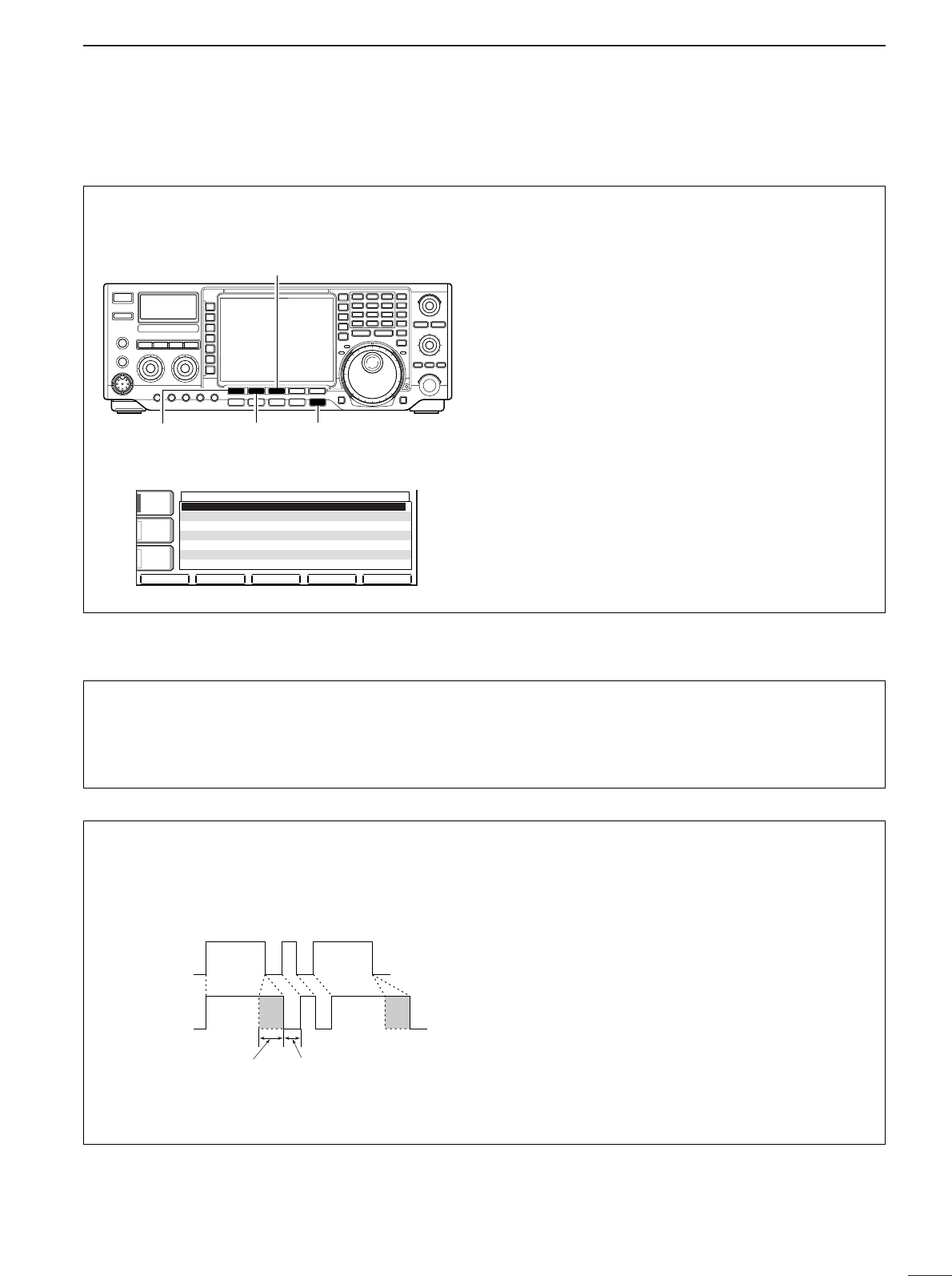
42
4
RECEIVE AND TRANSMIT
This set mode is used to set the CW side tone, mem-
ory keyer repeat time, dash weight, paddle specifica-
tions, keyer type, etc.
•Setting the electronic keyer
qPush [EXIT/SET] several times, if necessary.
wPush [CW/RTTY] to select CW mode.
ePush [(F-3)KEYER] then [EXIT/SET] to select
keyer set mode.
rPush [(F-4)CW KEY] to select memory keyer set
mode.
tPush [(F-1)∫] or [(F-2)√] to select the desired set
item.
ySet the desired condition using the tuning dial.
•Push [(F-3)DEF] for 1 sec. to select a default condition
or value.
uPush [EXIT/SET] twice to normal screen.
DEFDEF
KEYER CW-KEYKEYER CW-KEY
éè
KeyerKeyerRepeatRepeatTimeTime 2s 2s
Dot/DashDot/DashRatioRatio 1:1:3.01:1:3.0
RiseRiseTimeTime 4ms4ms
PaddlePaddlePolarityPolarity NormalNormal
KeyerKeyerTypeType ELEC-KEYELEC-KEY
MICMICUp/DownUp/DownKeyerKeyer OFFOFF
AGCAGC
MIDMID
1/41/4
OFFOFF
BK-INBK-IN
OFFOFF
[(F-2)√][(F-1)∫] [EXIT/SET]
[(F-3)DEL]
DDKeyer set mode
Keyer Repeat Time
(Keyer repeat time)
When sending CW using the repeat timer, this item
sets the time between transmission.
•1 to 60 sec. in 1 sec. steps can be selected.
(default: 2 sec.)
Dot/Dash Ratio (Dot/Dash ratio)
This item sets the dot/dash ratio. •1:1:2.8 to 1 : 1 : 4.5 can be set.
•Check the ratio with side tone in CW mode.
•Push [(F-3)DEF] to select a default ratio of 1 : 1 : 3.0.
Keying weight example: Morse code “K”
DASH
Weight setting:
1:1:3 (default)
Weight setting:
Adjusted
DASH
DOT (Fixed*)
Adjustable range SPACE (Fixed*)
*SPACE and DOT length can be adjusted with
[KEY SPEED] only.

43
4RECEIVE AND TRANSMIT
DDKeyer set mode (continued)
Rise Time (Rise time)
This item sets the envelop time period which the out-
put power becomes the set transmit power.
•2, 4, 6, or 8 msec. can be selected. (default: 4 msec.)
Key action
Tx output power
• About rise time
Rise time
Tx
Rx
Set Tx power level
Time
0
Paddle Polarity (Paddle polarity)
This item sets the paddle polarity. •Normal and reverse pooarity can be selected.
Keyer Type (Keyer type)
This item selects the keyer type for [.ELEC-KEY] con-
nector on the front panel.
•ELEC-KEY, BUG-KEY and Straight key can be se-
lected. (default: ELEC-KEY]
MIC Up/Down Keyer
(Microphone’s [UP]/[DN] switches keyer)
This item allows you to set the microphone [UP]/[DN]
switches to be used as a paddle.
•ON: [UP]/[DN] switches can be used for CW.
•OFF: [UP]/[DN] switches cannot be used for CW.
NOTE: When “ON” is selected, the frequency and
memory channel cnanot be changed using the
[UP]/[DN] switches.
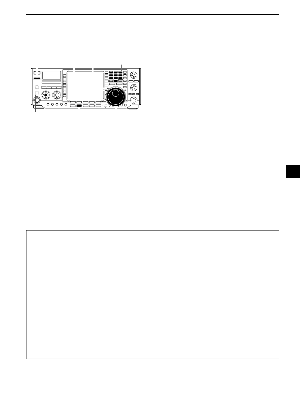
44
4
RECEIVE AND TRANSMIT
4
■Operating RTTY (FSK) When using your RTTY terminal or TNC, consult the
manual that comes with the RTTY terminal or TNC.
qPush a band key to select the desired band.
wPush [CW/RTTY] to select RTTY.
•After RTTY mode is selected, push [CW/RTTY] for 1
sec. to toggle between RTTY and RTTY-R modes.
•“RTTY” or “RTTY-R” appears.
ePush [(F-3)DECODE] to display the decoder
screen.
•The IC-756PROIII has a Baudot decoder.
rRotate the tuning dial to simultaneously tune a de-
sired signal.
•The S-meter indicates received signal strength when
signal is received.
tRotate [AF] to set audio to a comfortable listening
level.
yPush [TRANSMIT] to transmit.
•The TX indicator lights red.
uType from the connected PC’s keyboard to enter
the contents that you want to transmit.
•The text color will be changed when transmitted.
•Press one of [F-1] to [F-4] to transmit the TX memory
contents.
iPush [TRANSMIT] to return to receive.
[CW/RTTY][AF] Tuning dial
[TRANSMIT] [TX] indicator [RX] indicator Band keys
DConvenient functions for receive
•Preamp (p. 57)
➥Push [P.AMP] several times to set the preamp
OFF, preamp 1 ON or preamp 2 ON.
•“P.AMP1” or “P.AMP2” appears when the preamp 1 or
preamp 2 is set to ON, respectively. (depending on op-
erating frequency band)
•Attenuator (p. 57)
➥Push [ATT] several times to set the attenuator in
6dB steps.
•“ATT” and attenuation level appear when the attenua-
tor is set to ON.
•Noise blanker (p. 62)
➥Push [NB] switch to turn the noise blanker ON
and OFF.
•Noise blanker indicator (in [NB] switch) lights when the
noise blanker is set to ON.
➥Push [NB] for 1 sec. to enter the noise blanker
level set mode, then rotate tuning dial to adjust
the threshold level.
•Twin PBT (passband tuning) (p. 60)
➥Rotate [TWIN PBT] controls (inner/outer).
•Push [PBT CLR] to clear the settings.
•Noise reduction (p. 64)
➥Push [NR] switch to turn the noise reduction ON
and OFF.
•Rotate [NR] control to adjust the noise reduction level.
•Noise reduction indicator (in [NR] switch) lights when
the noise reduction is set to ON.
•AGC (auto gain control) (p. 59)
➥Push [AGC] switch several times to select
AGC FAST, AGC MID or AGC SLOW.
➥Push [AGC] for 1 sec. to enter the AGC set mode.
•Rotate tuning dial to adjust the time constant.
•1⁄4function (p. 27)
➥Push [1/4] to turn the 1⁄4function ON and OFF.
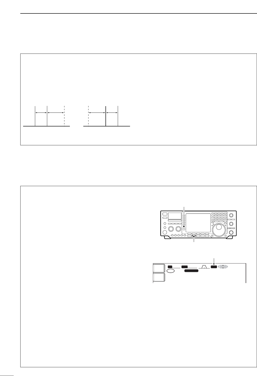
DRTTY filter/Twin peak filter
45
4RECEIVE AND TRANSMIT
The transceiver has 5 RTTY filters in addition to nor-
mal IF filters. The passband width can be selected
from 1 kHz, 500 Hz, 350 Hz, 300 Hz and 250 Hz.
When the RTTY filter is turned ON, the RTTY tuning
meter can be used. (p. 47)
Moreover, the twin peak filter changes the receive fre-
quency response by boosting 2 particular frequencies
(2125 and 2295 Hz) for better copying of desired RTTY
signals.
qPush [CW/RTTY] once or twice to select RTTY
mode.
wPush [RTTY FIL] to turn the RTTY filter ON.
•“TPF” appears when the twin peak filter is turned ON.
•RTTY filter selection
qPush [EXIT/SET] several times to close a multi-
function screen, if necessary.
wSelect RTTY mode.
ePush [RTTY FIL] for 1 sec. to enter RTTY filter set
mode.
rPush [(F-1)Y] to select band width item.
tRotate the tuning dial to select the RTTY filter
width from 1 kHz, 500 Hz, 350 Hz, 300 Hz and
250 Hz.
•Push [(F-3)DEF] for 1 sec. to select a default value.
yPush [(F-2)Z] to select twin peak filter item.
•The received audio volume may become greater when
the twin peak filter is turned ON.
uRotate the tuning dial to turn the twin peak filter
function ON or OFF.
iPush [EXIT/SET] to exit the RTTY filter set mode.
BWBW 350350 SFTSFT 0
VFOVFO FIL2FIL2
RTTYRTTY
qw:pp
TXTX
1CWCW
qr.qpp.pp
21.076.5021.076.50
TPFTPF
METERMETER
PoPo
ANTANT
1
[RTTY FIL]
[CW/RTTY]
TPF indicator
DAbout RTTY reverse mode
Received characters are occasionally garbled when
the receive signal is reversed between MARK and
SPACE. This reversal can be caused by incorrect
TNC connections, settings, commands, etc.
To receive a reversed RTTY signal correctly, select
RTTY-R (RTTY Reverse) mode.
qPush [CW/RTTY] once or twice to select RTTY
mode.
wPush [CW/RTTY] for 1 sec. to select RTTY or
RTTY-R mode.
•Check the receive signal.
Normal Reverse
Space Mark BFO Space Mark
BFO
170 Hz 2125 Hz 170 Hz2125 Hz
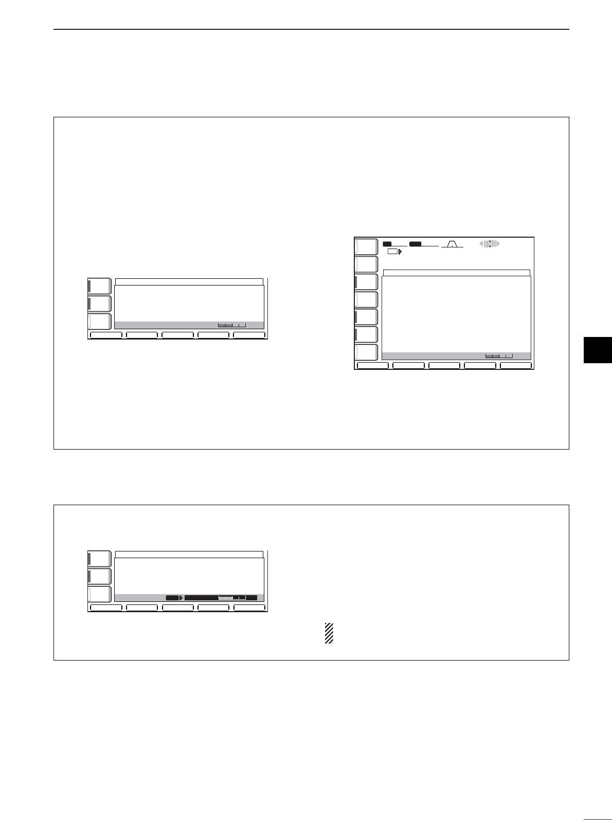
46
4
RECEIVE AND TRANSMIT
4
DFunctions for the RTTY decoder indication
The transceiver has an RTTY decoder for Baudot
(mark freq.: 2125 Hz, shift freq.: 170 Hz, 45 bps).
An external terminal unit (TU) or terminal node con-
troller (TNC) is not necessary for receiving a Baudot
signal.
qPush [EXIT/SET] several times to close a multi-
function screen, if necessary.
wPush [CW/RTTY] to select RTTY mode.
ePush [(F-3)DECODE] to turn the RTTY decoder
ON.
•RTTY decoder screen appears.
rIf the RTTY filter is turned OFF, push [RTTY FIL]
to turn the function ON.
•The RTTY decoder does not function when the RTTY
filter is turned OFF.
tPush [(F-2)HOLD/CLR] momentarily to freeze the
current screen.
•“HOLD” appears while the function is in use.
yPush [(F-5)WIDE] to toggle the normal or wide
screen space.
uPush [(F-2)HOLD/CLR] for 1 sec. to clear the dis-
played characters.
iPush [EXIT/SET] to exit the RTTY decoder screen.
SFTSFT 0
qw:pp
BWBW 350 350
RTTY DECODERTTY DECODE
VFOVFO
VFOVFO
qr≥qot≥pp
14.100.00
RTTY RTTY FILFIL2
RTTY RTTY FILFIL2
TXTX
AGCAGC
MIDMID
1/41/4
OFFOFF
RTTYRTTY
FILFIL
ONON
METERMETER
PoPo
P.AMPP.AMP
1
ATTATT
OFFOFF
ANTANT
1
<MENU1><MENU1> TX MEMTX MEM
HLD/CLRHLD/CLR ADJADJ WIDEWIDE
********RTTYRTTYDecodeDecodeMonitorMonitor********
45bps45bpsBAUDOTBAUDOTMark=2125,Mark=2125,Shift=170Shift=170
UnShiftUnShiftOnOnSpaceSpacesupportsupport(SET-OTHERS)(SET-OTHERS)
NewNewLineLineCodeCodeselectableselectable(SET-OTHERS)(SET-OTHERS)
IfIfRTTY-FILRTTY-FILisisOFF,OFF,PleasePleaseturnturnON.ON.
----------------------------------------------------------------------------------------
CQ CQ CQ THIS IS JA3YUA JA3YUA OSAKA JAPANCQ CQ CQ THIS IS JA3YUA JA3YUA OSAKA JAPAN
CQ CQ CQ THIS IS JA3YUA JA3YUA OSAKA JAPANCQ CQ CQ THIS IS JA3YUA JA3YUA OSAKA JAPAN
CQ CQ CQ THIS IS JA3YUA JA3YUA OSAKA JAPANCQ CQ CQ THIS IS JA3YUA JA3YUA OSAKA JAPAN
THRESHOLDTHRESHOLD 9
AGCAGC
MIDMID
1/41/4
OFFOFF
RTTYRTTY
FILFIL
ONON
<MENU1><MENU1> HLD/CLRHLD/CLR TX MEMTX MEM ADJADJ WIDEWIDE
********RTTYRTTYDecodeDecodeMonitorMonitor********
45bps45bpsBAUDOTBAUDOTMark=2125,Mark=2125,Shift=170Shift=170
UnShiftUnShiftOnOnSpaceSpacesupportsupport(SET-OTHERS)(SET-OTHERS)
NewNewLineLineCodeCodeselectableselectable(SET-OTHERS)(SET-OTHERS)
IfIfRTTY-FILRTTY-FILisisOFF,OFF,PleasePleaseturnturnON.ON.
----------------------------------------------------------------------------------------
THRESHOLDTHRESHOLD 9
RTTY DECODERTTY DECODE
DSetting the decoder threshold level
Adjust the RTTY decoder threshold level if some
characters are displayed when no signal is received.
qCall up the RTTY decoder screen as described at
left.
wPush [(F-4)ADJ] to select the threshold level set-
ting condition.
eRotate the tuning dial to adjust the RTTY decoder
threshold level.
•Push [(F-3)DEF] to select the default condition.
rPush [EXIT/SET] to exit the RTTY decoder screen.
The UnShift On Space (USOS) function and new
line code can be set in the RTTY set mode. (p. 49)
THRESHOLD
THRESHOLD
9
9
ADJ
ADJ
AGC
AGC
MID
MID
1/4
1/4
OFF
OFF
RTTY
RTTY
FIL
FIL
ON
ON
DEF
DEF
ADJ
ADJ
WIDE
WIDE
****
****
RTTY
RTTY
Decode
Decode
Monitor
Monitor
****
****
45bps
45bps
BAUDOT
BAUDOT
Mark=2125,
Mark=2125,
Shift=170
Shift=170
UnShift
UnShift
On
On
Space
Space
support
support
(SET-OTHERS)
(SET-OTHERS)
New
New
Line
Line
Code
Code
selectable
selectable
(SET-OTHERS)
(SET-OTHERS)
If
If
RTTY-FIL
RTTY-FIL
is
is
OFF,
OFF,
Please
Please
turn
turn
ON.
ON.
--------------------------------------------
--------------------------------------------
RTTY DECODE
RTTY DECODE
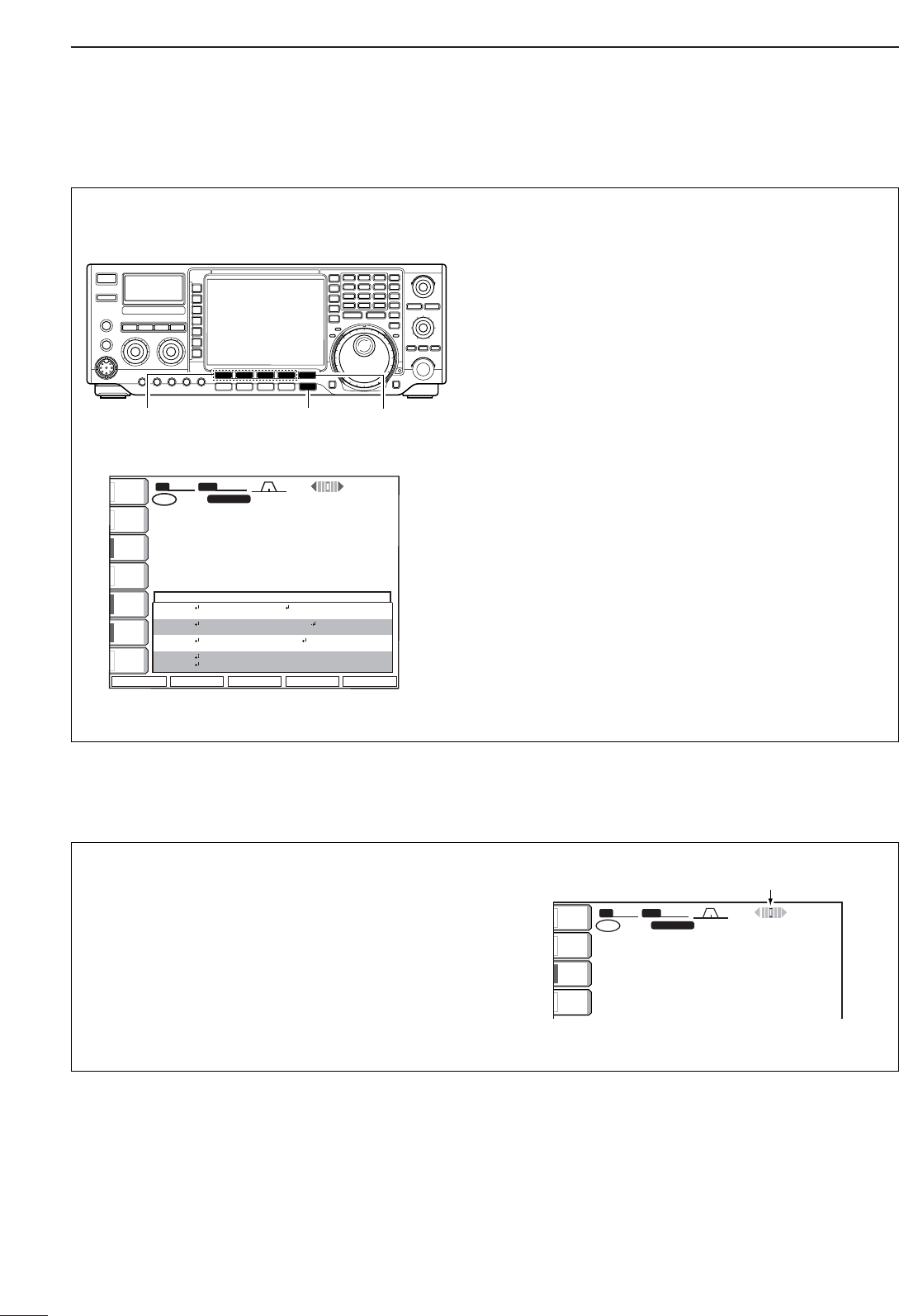
47
4RECEIVE AND TRANSMIT
DRTTY memory transmission
Pre-set characters can be sent using the RTTY mem-
ory. Contents of the memory are set using the edit
menu.
qPush [EXIT/SET] several times to close a multi-
function screen, if necessary.
wPush [CW/RTTY] to select RTTY mode.
ePush [(F-3)DECODE] to turn the RTTY decoder
ON.
rPush [(F-3)TX MEM] to select RTTY memory
screen.
tPush [(F-5)1-4/5-8] to select memory bank then
push one of the function keys [(F-1)RT1] to [(F-
4)RT4] or [(F-1)RT5] to [(F-4)RT8].
•The selected memory contents will be transmitted im-
mediately.
ANTANT
1
METERMETER
PoPo
P.AMPP.AMP
1
ATTATT
0FF0FF
RTTYRTTY
FILFIL
ONON
1/41/4
OFFOFF
BWBW 350350 SFTSFT
VFOVFO FIL2FIL2
RTTYRTTY
qw:pp
AGCAGC
MIDMID
1
21. 085. 0021. 085. 00
21. 085. 0021. 085. 00
TXTX
VFOVFO
1
USBUSB
CWCW
CWCW
FIL2FIL2
RT1RT1 RT2RT2 RT3RT3
0
qr.qpp.pp
qr.qpp.pp
12:0012:00
RT4RT4 1-4/5-81-4/5-8
RTTY MEMORYRTTY MEMORY
RT1RT1
RT2RT2
RT3RT3
RT4RT4
DEDE ICOMICOM ICOMICOM K
QSLQSL URUR 599-599599-599 BKBK
QSLQSL DEDE ICOMICOM ICOMICOM URUR 599-599599-599 BKBK
DEDE ICOMICOM ICOMICOM ICOM KICOM K
[(F-1)RT1]–[(F-4)RT4]
[(F-1)RT5]–[(F-4)RT8]
[EXIT/SET] [(F-5)1-4/5-8]
DRTTY tuning meter
The transceiver has an RTTY tuning indicator to be
tuned correctly and easily.
The RTTY tuning meter is automatically displayed
when the RTTY filter is turned ON.
qPush [CW/RTTY] to select RTTY mode.
wPush [RTTY FIL] to activate the RTTY filter and
RTTY tuning meter.
SFTSFT 0
FIL2FIL2
RTTYRTTY
qw:pp
TXTX
VFOVFO USBUSB
USBUSB
USBUSB
FIL2FIL2
qr.qot.pp
qr.wpt.pp
14.100.0014.100.00
14.100.0014.100.00
1
1
VFOVFO
BWBW 350 350
METERMETER
PoPo
P.AMPP.AMP
1
ATTATT
OFFOFF
ANTANT
1
RTTY tuning meter
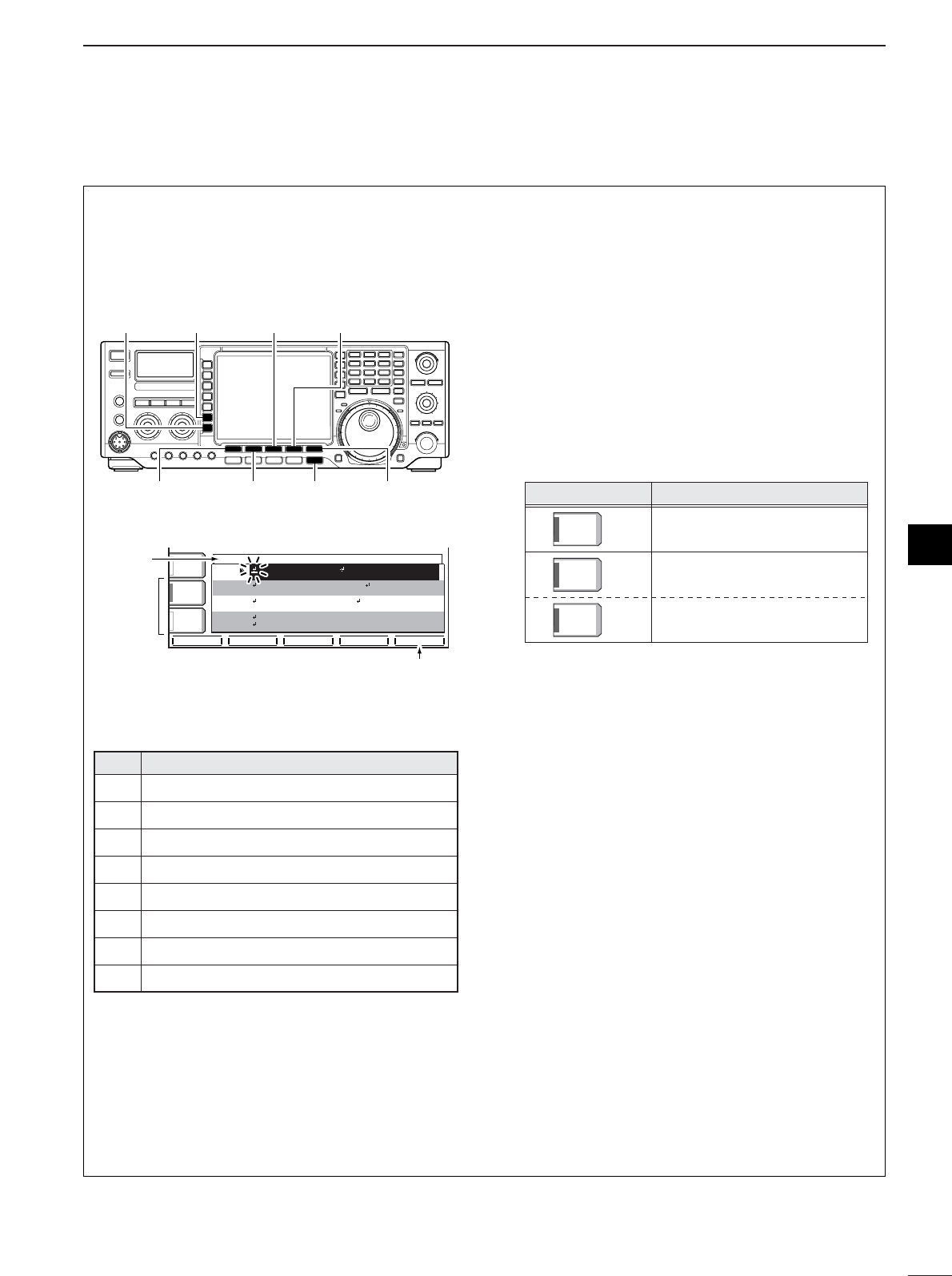
48
4
RECEIVE AND TRANSMIT
4
The contents of the RTTY memories can be set using
the memory edit menu. The memory can memorize
and re-transmit 8 RTTY contents for often-used RTTY
sentences. Total capacity of the memory is 70 char-
acters per memory channel.
• Pre-programmed contents
•Programming contents
qPush [EXIT/SET] several times, if necessary.
wPush [CW/RTTY] to select RTTY mode.
ePush [(F-3)DECODE] then [(F-1)MENU1] to select
the RTTY decode menu 2.
rPush [(F-2)EDIT] to enter the RTTY memory edit
screen.
tPush [(F-5)RT1..8] several times to select the de-
sired memory channel.
ySelect the desired character group by pushing the
character group keys ([ABC], [123] or [etc]) several
times.
•[etc] appears when [123] is pushed when “123” char-
acter group is selected.
•Selectabel characters (with the tuning dial);
uSelect the desired character by rotating the tuning
dial or by pushing the band key for number input.
•Push [(F-1)Ω] or [(F-2)≈] for cursor movement.
•Push [(F-3)DEL] to delete the selected character.
•Push [(F-4)SPACE] to input a space.
iRepeat step uuntil the desired contents are input.
oPush [(F-5)RT1..8] to select the next memory
channel and repeat step ufor character input, if
desired.
!0 Push [EXIT/SET] to set the contents and exit
RTTY memory edit screen.
Key selection
ABCABC
Editable characters
A to Z (capital leters)
123123
0 to 9 (numbers)
/ ? ^ . , @ ✽
etcetc
CH Contents
↵DE ICOM ICOM K↵
↵DE ICOM ICOM ICOM K↵
↵QSL UR 599–599 BK↵
RT1
RT2
RT3
↵QSL DE ICOM ICOM UR 599–599 BK↵
RT4
↵CQ CQ CQ DE ICOM ICOM ICOM K↵
RT6
RT7
RT8
↵73 GL SK↵
(blank)
(blank)
RT5
RTTY MEMORY EDITRTTY MEMORY EDIT
RT1RT1
RT2RT2
RT3RT3
RT4RT4
QSLQSL URUR 599-599599-599 BKBK
QSLQSL DEDE ICOMICOM ICOMICOM URUR 599-599599-599 BKBK
DEDE ICOMICOM ICOMICOM ICOM KICOM K
çåDELDEL SPACESPACE RT1..8RT1..8
ABCABC
ABCABC
123123
DEDE ICOMICOM ICOMICOM K
Character
group
keys
Selected
character
Memory ch
select
[(F-2)≈][(F-1)Ω]
[123]/[etc] [ABC]
[EXIT/SET] [(F-5)RT1..8]
[(F-3)DEL] [(F-4)SPACE]
DDEditing RTTY memory
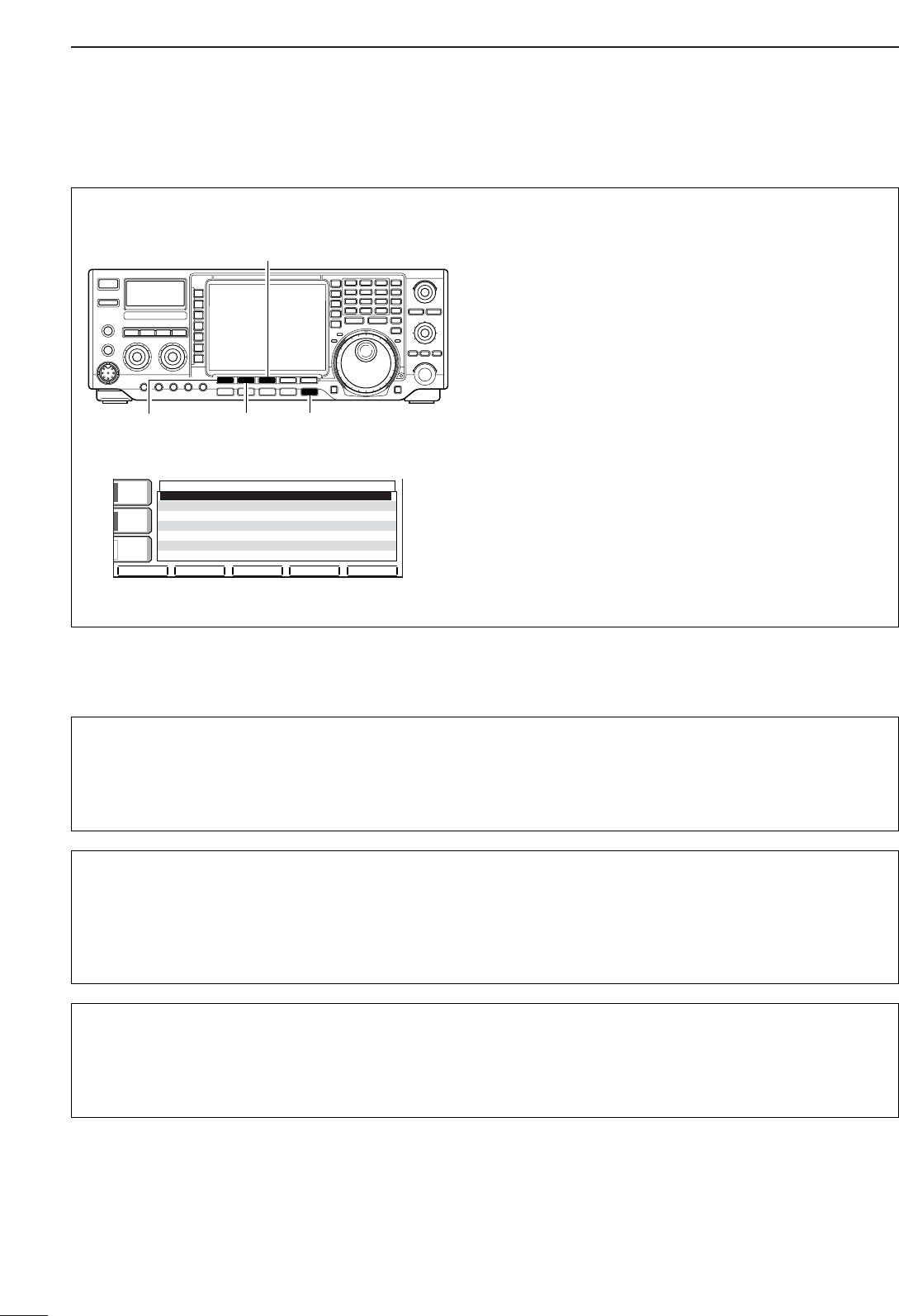
49
4RECEIVE AND TRANSMIT
RRTTTTYY DDeeccooddee UUSSOOSS
This item selects the USOS (UnShift On Space) func-
tion of the internal RTTY decoder.
OONN
Decode as letter code
(default)
OOFFFF
Decode as character code
RRTTTTYY TTXX UUSSOOSS
This item selects the FIGS insertion even changing
from LTRS to FIGS does not necessary when send-
ing a numeral or symbol character agter a space.
OONN
Inserts FIGS
(default)
OOFFFF
Not insert FIGS
RRTTTTYY DDeeccooddee NNeeww LLiinnee CCooddee
This item selects the new line code of the internal
RTTY decoder.
CR : Carriage Return
LF : Line Feed
CCRR,,LLFF,,CCRR++LLFF
CR, LF and CR+LF
(default)
CCRR++LLFF
CR+LF only
DRTTY decoder set mode
This set mode is used to set the decode USOS func-
tion, etc. •Setting the contents
qPush [EXIT/SET] several times, if necessary.
wPush [CW/RTTY] to select RTTY mode.
ePush [(F-3)DECODE] then [(F-1)MENU1] to select
RTTY decode menu 2.
rPush [(F-4)SET] to select RTTY decode set mode.
tPush [(F-1)∫] or [(F-2)√] to select the desired set
item.
ySet the desired condition using the tuning dial.
•Push [(F-3)DEF] for 1 sec. to select a default condition
or value.
uPush [EXIT/SET] to exit from set mode.
DEFDEF
RTTY DECODE SETRTTY DECODE SET
éè
RTTYRTTYDecodeDecodeUSOSUSOS ONON
RTTYRTTYDecodeDecodeNewNewLineLineCodeCode CR,LF,CR+LFCR,LF,CR+LF
RTTYRTTYTXTXUSOSUSOS ONON
AGCAGC
MIDMID
1/41/4
OFFOFF
RTTYRTTY
FILFIL
ONON
[(F-2)√][(F-1)∫] [EXIT/SET]
[(F-3)DEL]
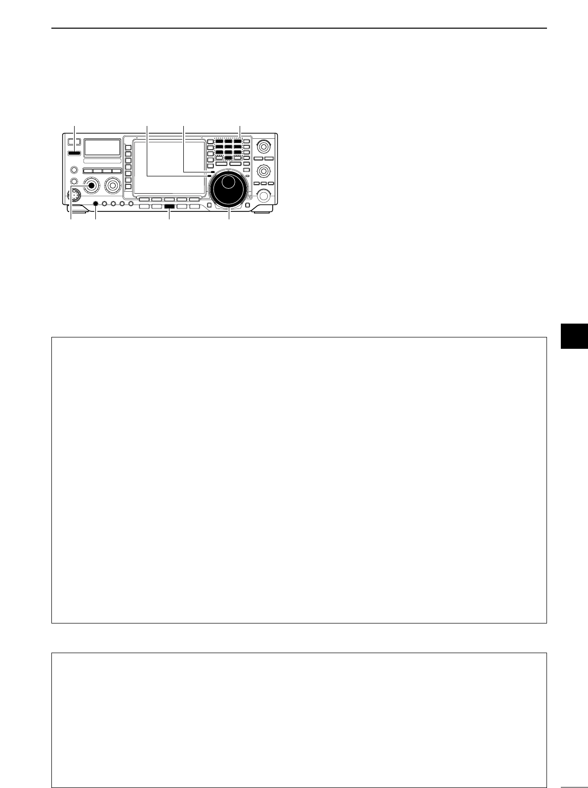
50
4
RECEIVE AND TRANSMIT
4
DConvenient functions for receive
■Operating AM qPush a band key to select the desired band.
wPush [AM/FM] to select AM.
•“AM” indicator appears.
•After AM mode is selected, push [AM/FM] to toggle be-
tween AM and FM modes.
eRotate the tuning dial to tune a desired frequency.
•The S-meter indicates received signal strength when
signal is received.
rRotate [AF] to set audio to a comfortable listening
level.
tPush [TRANSMIT] or [PTT] (microphone) to trans-
mit.
•The TX indicator lights red.
ySpeak into the microphone at your normal voice
level.
•Adjust the microphone gain with [MIC] at this step, if
necessary.
uPush [TRANSMIT] or release [PTT] (microphone) to
return to receive.
[TRANSMIT]
[AM/FM][AF] [MIC GAIN] Tuning dial
[TX] indicator [RX] indicator Band keys
•Preamp (p. 57)
➥Push [P.AMP] several times to set the preamp
OFF, preamp 1 ON or preamp 2 ON.
•“P.AMP1” or “P.AMP2” appears when the preamp 1 or
preamp 2 is set to ON, respectively. (depending on op-
erating frequency band)
•Attenuator (p. 57)
➥Push [ATT] several times to set the attenuator in
6dB steps.
•“ATT” and attenuation level appear when the attenua-
tor is set to ON.
•Noise blanker (p. 62)
➥Push [NB] switch to turn the noise blanker ON
and OFF.
•Noise blanker indicator (in [NB] switch) lights when the
noise blanker is set to ON.
➥Push [NB] for 1 sec. to enter the noise blanker
level set mode, then rotate tuning dial to adjust
the threshold level.
•Twin PBT (passband tuning) (p. 62)
➥Rotate [TWIN PBT] controls (inner/outer).
•Push [PBT CLR] to clear the settings.
•Noise reduction (p. 64)
➥Push [NR] switch to turn the noise reduction ON
and OFF.
•Rotate [NR] control to adjust the noise reduction level.
•Noise reduction indicator (in [NR] switch) lights when
the noise reduction is set to ON.
•Notch filter (p. 64)
➥Push [NOTCH] switch to turn the auto or manual
notch function ON and OFF.
•Rotate [NOTCH] control to set the attenuating fre-
quency for manual notch operation.
•Notch indicator (in [NOTCH] switch) lights when either
the auto or manual notch is set to ON.
•AGC (auto gain control) (p. 59)
➥Push [AGC] switch several times to select
AGC FAST, AGC MID or AGC SLOW.
➥Push [AGC] for 1 sec. to enter the AGC set mode.
•Rotate tuning dial to adjust the time constant.
DConvenient functions for transmit
•Transmit quality monitor (p. 59)
➥Push [MONITOR] to turn the monitor function ON
and OFF.
•Monitor indicator (in [MONI] switch) lights when the
monitor function is set to ON.
➥Push [EXIT/SET] for 1 sec. then [(F-1)LEVEL] to
enter level set mode. Select the monitor level item
with [(F-1)Y]/[(F-2)Z] then rotate the tuning dial
to adjust the monitor gain.
•VOX (voice operated transmit) (p. 65)
➥Push [VOX] to turn the VOX function ON and
OFF.
•“VOX ON” appears when the VOX function is set to
ON.
•Audio tone control (p. 93)
➥Push [EXIT/SET] for 1 sec. then [(F-1)LEVEL] to
enter level set mode. Select an item with [(F-
1)Y]/[(F-2)Z] then rotate the tuning dial to adjust
the audio tone.

51
4RECEIVE AND TRANSMIT
DConvenient functions for receive
■Operating FM qPush a band key to select the desired band.
wPush [AM/FM] to select FM.
•“FM” indicator appears.
•After FM mode is selected, push [AM/FM] to toggle be-
tween FM and AM modes.
eRotate the tuning dial to tune a desired frequency.
•The S-meter indicates received signal strength when
signal is received.
•10 kHz tuning step is preset for FM mode.
rRotate [AF] to set audio to a comfortable listening
level.
tPush [TRANSMIT] or [PTT] (microphone) to trans-
mit.
•The TX indicator lights red.
ySpeak into the microphone at your normal voice
level.
•Adjust the microphone gain with [MIC] at this step, if
necessary.
uPush [TRANSMIT] or release [PTT] (microphone) to
return to receive.
[TRANSMIT]
[AM/FM][AF] [MIC GAIN] Tuning dial
[TX] indicator [RX] indicator Band keys
•Preamp (p. 57)
➥Push [P.AMP] several times to set the preamp
OFF, preamp 1 ON or preamp 2 ON.
•“P.AMP1” or “P.AMP2” appears when the preamp 1 or
preamp 2 is set to ON, respectively. (depending on op-
erating frequency band)
•Attenuator (p. 57)
➥Push [ATT] several times to set the attenuator in
6dB steps.
•“ATT” and attenuation level appear when the attenua-
tor is set to ON.
•Notch filter (p. 64)
➥Push [NOTCH] switch to turn the auto notch func-
tion ON and OFF.
•Rotate [NOTCH] control to set the attenuating fre-
quency for manual notch operation.
•Notch indicator (in [NOTCH] switch) lights when the
auto notch is set to ON.
DConvenient functions for transmit
•Transmit quality monitor (p. 64)
➥Push [MONITOR] to turn the monitor function ON
and OFF.
•Monitor indicator (in [MONI] switch) lights when the
monitor function is set to ON.
➥Push [EXIT/SET] for 1 sec. then [(F-1)LEVEL] to
enter level set mode. Select the monitor level item
with [(F-1)Y]/[(F-2)Z] then rotate the tuning dial
to adjust the monitor gain.
•VOX (voice operated transmit) (p. 65)
➥Push [VOX] to turn the VOX function ON and
OFF.
•“VOX ON” appears when the VOX function is set to
ON.
•Audio tone control (p. 93)
➥Push [EXIT/SET] for 1 sec. then [(F-1)LEVEL] to
enter level set mode. Select an item with [(F-
1)Y]/[(F-2)Z] then rotate the tuning dial to adjust
the audio tone.
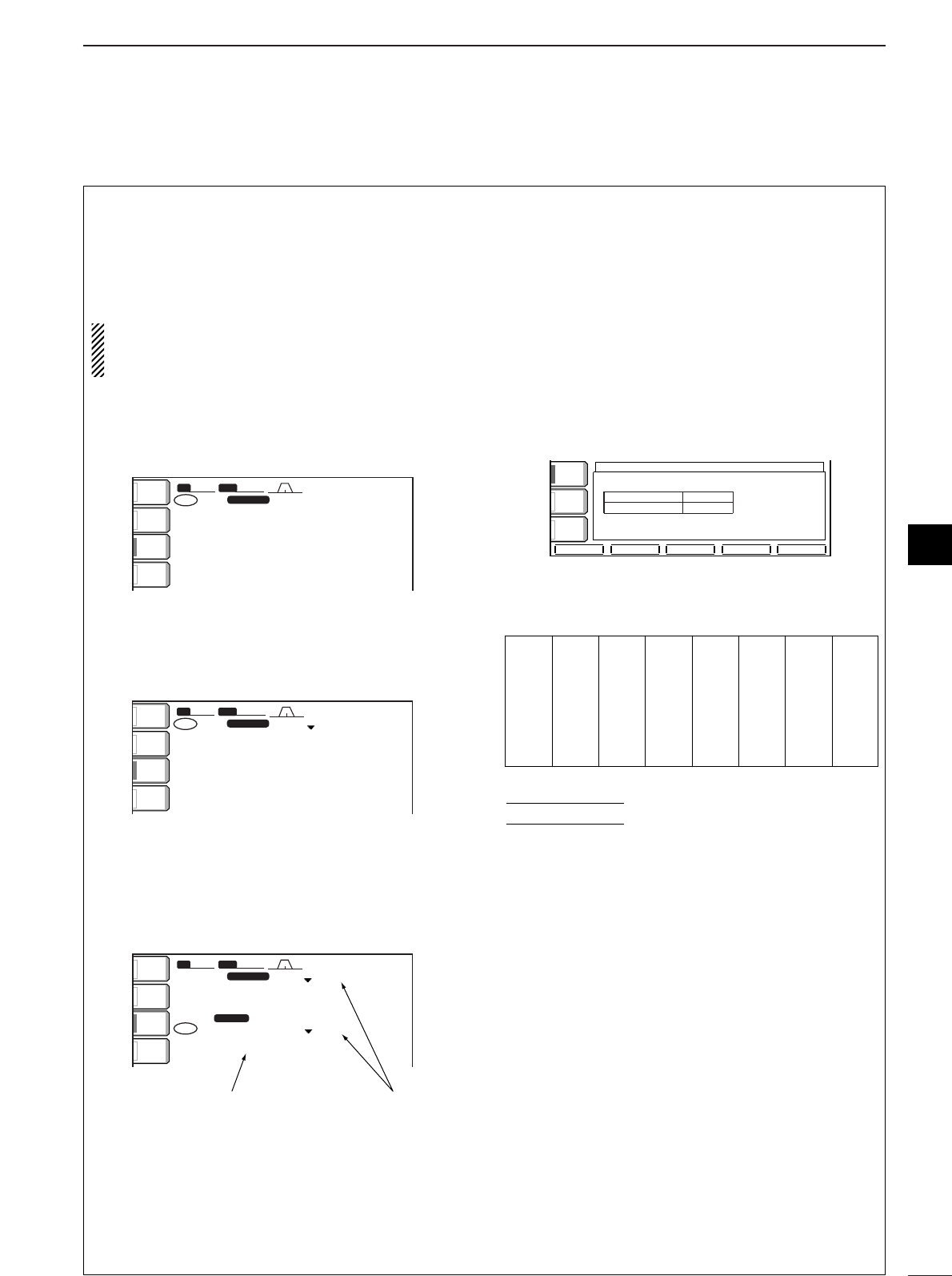
52
4
RECEIVE AND TRANSMIT
■Repeater operation
Arepeater amplifies received signals and retransmits
them at a different frequency. When using a repeater,
the transmit frequency is shifted from the receive fre-
quency by an offset frequency. A repeater can be ac-
cessed using split frequency operation with the shift
frequency set to the repeater’s offset frequency.
For accessing a repeater which requires a repeater
tone, set the repeater tone frequency in set mode
as described below.
qSet the offset frequencies (HF, 50 MHz) and turn
ON the quick split function in set mode (others) in
advance. (p. 69)
wPush [VFO/MEMO] to select VFO mode.
ePush the desired band key.
rPush [AM/FM] several times to select FM mode.
tSet the receive frequency (repeater output fre-
quency).
yPush [SPLIT] for 1 sec. to start repeater operation.
•Repeater tone is turned ON automatically.
•Shifted transmit frequency and “TX” appear in the sub
readout.
•The transmit frequency can be monitored while pushing
[XFC] or using dualwatch.
uPush and hold [PTT] to transmit; release [PTT] to
receive.
iTo return to simplex, push [SPLIT] momentarily to
clear the sub display.
•Setting the repeater tone
Some repeaters require subaudible tones to be ac-
cessed. Subaudible tones are superimposed over
your normal signal and must be set in advance. The
transceiver has 50 tones from 67.0 Hz to 254.1 Hz.
Each memory channel can store an independent set-
ting.
qSelect FM mode.
wPush [TONE] for 1 sec. to enter tone set mode.
ePush [(F-1)∫] to select the repeater tone item.
rRotate the tuning dial to select the desired re-
peater tone frequency.
tPush [EXIT/SET] to exit tone set mode.
Available repeater tones (Unit: Hz)
Store repeater tone frequencies and ON/OFF settings
in memory channels for easy recall.
CONVENIENT
T-SCANT-SCAN
éèDEFDEF
TONE FREQUENCYTONE FREQUENCY
88.5Hz88.5Hz
88.5Hz88.5HzT-SQL TONET-SQL TONE
REPEATER TONEREPEATER TONE
AGCAGC
FASTFAST
VOXVOX
OFFOFF
TONETONE
OFFOFF
BWBW 15k15k SFTSFT 0
FIL2FIL2
FMFM
qw:pp
VFOVFO FMFM
USBUSB
USBUSB
FIL2FIL2
wo.yip.pp
wo.tip.pp
14.100.0014.100.00
14.100.0014.100.00
1
1
VFOVFO
SPLITSPLIT
TXTX
TONETONE
TONETONE
ANTANT
1
METERMETER
PoPo
ATTATT
OFFOFF
P.AMPP.AMP
1
Tone encoder is auto-
matically turned ON.
Shifted frequency appears.
BWBW 15k15k SFTSFT 0
FIL2FIL2
FMFM
qw:pp
TXTX
VFOVFO USBUSB
USBUSB
USBUSB
FIL2FIL2
wo.yip.pp
qr.wpt.pp
14.100.0014.100.00
14.100.0014.100.00
1
1
VFOVFO
ANTANT
1
METERMETER
PoPo
ATTATT
OFFOFF
P.AMPP.AMP
1
BWBW 2.4k2.4k SFTSFT 0
FIL2FIL2
USBUSB
qw:pp
TXTX
VFOVFO USBUSB
USBUSB
USBUSB
FIL2FIL2
wq.wop.pp
qr.wpt.pp
14.100.0014.100.00
14.100.0014.100.00
1
1
VFOVFO
ANTANT
1
METERMETER
PoPo
ATTATT
OFFOFF
P.AMPP.AMP
1
67.0
69.3
71.9
74.4
77.0
79.7
82.5
085.4
088.5
091.5
094.8
097.4
100.0
103.5
107.2
110.9
114.8
118.8
123.0
127.3
131.8
136.5
141.3
146.2
151.4
156.7
159.8
162.2
165.5
167.9
171.3
173.8
177.3
179.9
183.5
186.2
189.9
192.8
196.6
199.5
203.5
206.5
210.7
218.1
225.7
229.1
233.6
241.8
250.3
254.1
4
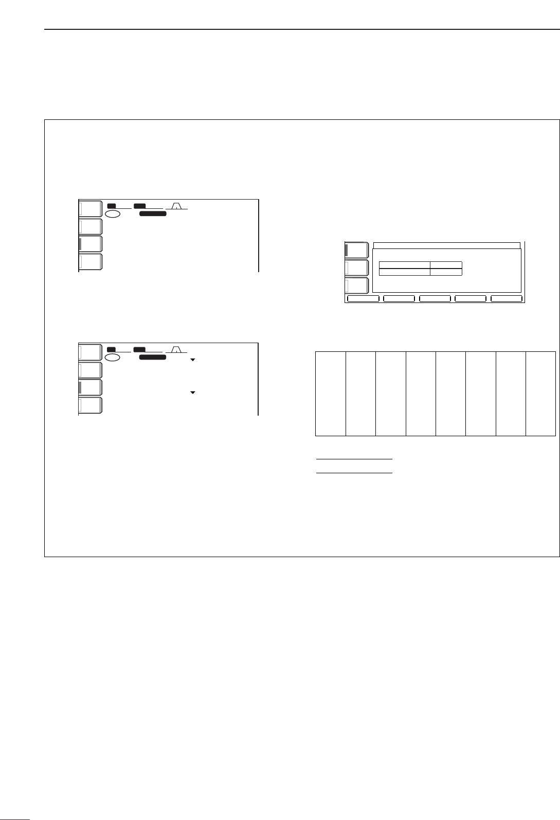
53
4RECEIVE AND TRANSMIT
■Tone squelch operation
The tone squelch opens only when receiving a signal
containing a matching subaudible tone. You can
silently wait for calls from group members using the
same tone.
qPush [VFO/MEMO] to select VFO mode.
wPush the desired band key.
ePush [AM/FM] several times to select FM mode.
rPush [TONE] several times until “TSQL” appears
in the function display.
tWhen the received signal includes a matching
tone, squelch opens and the signal can be heard.
•When the received signal’s tone does not match, tone
squelch does not open, however, the S-indicator shows
signal strength.
•To open the squelch manually, push [XFC].
yOperate the transceiver in the normal way.
uTo cancel the tone squelch, push [TONE] to clear
“TSQL.”
•Setting the tone squelch tone
The transceiver has 50 tones from 67.0 Hz to
254.1 Hz.
qSelect FM mode.
wPush [TONE] for 1 sec. to enter tone set mode.
ePush [(F-2)√] to select the tone squelch tone item.
rRotate the tuning dial to select the desired tone
squelch frequency.
tPush [EXIT/SET] to exit tone set mode.
Available tone squelch tones (Unit: Hz)
Store tone squelch frequencies and ON/OFF settings
in memory channels for easy recall.
CONVENIENT
T-SCANT-SCAN
éèDEFDEF
TONE FREQUENCYTONE FREQUENCY
88.5Hz88.5Hz
88.5Hz88.5HzT-SQL TONET-SQL TONE
REPEATER TONEREPEATER TONE
AGCAGC
FASTFAST
VOXVOX
OFFOFF
TONETONE
OFFOFF
BWBW 15k15k SFTSFT 0
FIL2FIL2
FMFM
qw:pp
VFOVFO FMFM
USBUSB
USBUSB
FIL2FIL2
wo.yip.pp
wo.tip.pp
14.100.0014.100.00
14.100.0014.100.00
1
1
VFOVFO TSQLTSQL
TSQLTSQL
TXTX
ANTANT
1
METERMETER
PoPo
ATTATT
OFFOFF
P.AMPP.AMP
1
BWBW 2.4k2.4k SFTSFT 0
FIL2FIL2
USBUSB
qw:pp
TXTX
VFOVFO USBUSB
USBUSB
USBUSB
FIL2FIL2
wq.wop.pp
qr.wpt.pp
14.100.0014.100.00
14.100.0014.100.00
1
1
VFOVFO
ANTANT
1
METERMETER
PoPo
ATTATT
OFFOFF
P.AMPP.AMP
1
67.0
69.3
71.9
74.4
77.0
79.7
82.5
085.4
088.5
091.5
094.8
097.4
100.0
103.5
107.2
110.9
114.8
118.8
123.0
127.3
131.8
136.5
141.3
146.2
151.4
156.7
159.8
162.2
165.5
167.9
171.3
173.8
177.3
179.9
183.5
186.2
189.9
192.8
196.6
199.5
203.5
206.5
210.7
218.1
225.7
229.1
233.6
241.8
250.3
254.1
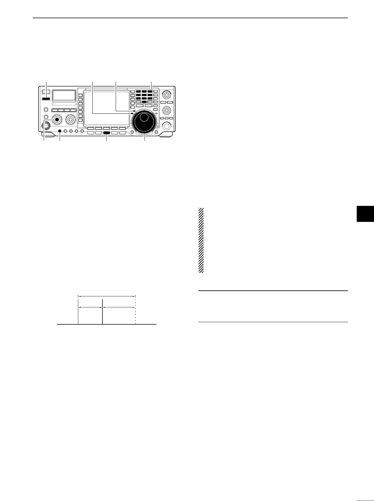
54
4
RECEIVE AND TRANSMIT
■Data mode (SSTV/PSK31) operation
4
When operating SSTV or PSK31 with your PC soft-
ware, consult the manual that comes with the software.
qConnect a PC to the transceiver. (p. 19)
wPush a band key to select the desired band.
ePush [SSB] or [AM/FM] to select the desired oper-
ating mode.
rPush the same key for 1 sec. to turn data mode ON.
•“-D” indicator additionally appears.
tRotate the main dial to tune into the desired signal
and decoded correctly.
•Also use the tuning indicator of the software.
• During SSB data mode, 1⁄4tuning function can be used
for critical tuning.
yOperate the PC (software) to transmit.
•When operating in SSB data mode, adjust the AF output
level from PC so that the ALC meter reading doesn’t go
outside the ALC zone.
NOTE: When SSB data mode is selected, the audio
input from the [ACC1] (pin 6) is used for transmis-
sion instead of [MIC]’s.
The fixed condition is used for SSB data transmis-
sion as follow.
•[COMP] : OFF
•Tx bandwidth : MID
•Tx Tone (Bass) : 0
•Tx Tone (Trebles) : 0
✔
For your information
Carrier point frequency is displayed when SSB data
mode is selected.
See the diagram left for the tone-pair example.
200 Hz 2125 Hz
2325 Hz
Carrier point
(displayed frequency)
[TRANSMIT]
[AM/FM]
[AF] [MIC GAIN] Tuning dial
[TX] indicator [RX] indicator Band keys
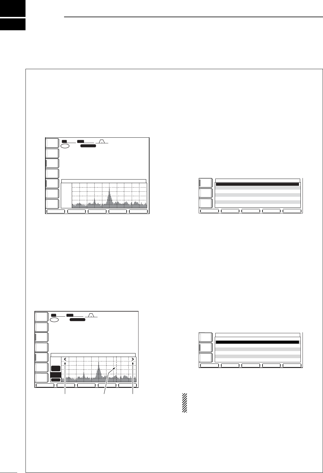
■Spectrum scope screen
This function allows you to display the relative
strengths of signals around the center frequency. The
span can be set to ±12.5 kHz, ±25 kHz, ±50 kHz and
±100 kHz. Ideal for monitoring band conditions in an
instant.
qPush [EXIT/SET] several times to close a multi-
function screen, if necessary.
wPush [(F-1)SCOPE] to select the scope screen.
ePush [(F-1)SPAN] several times to select the
scope span.
rPush [(F-2)ATT] several times to activate an atten-
uator or turn the attenuator OFF.
•10, 20 and 30 dB attenuators are available.
tPush [(F-3)MARKER] several times to select the
marker (sub readout or transmit frequency) or turn
the marker OFF.
•“TX MARKER” displays the marker at the transmit fre-
quency.
•“SUB MARKER” displays the marker at the sub readout
frequency.
yPush [(F-4)HOLD] to freeze the current spectrum
waveform.
•“HOLD” appears while the function is in use.
uPush [EXIT/SET] to exit the scope screen.
•Spectrum scope during transmitting
The spectrum scope shows the transmit signal wave-
form while transmitting. This can be deactivated if de-
sired.
When “OFF” is selected, the spectrum scope holds
the received waveform while transmitting and does
not show the transmit waveform.
qCall up the scope screen as described at left.
wPush [(F-5)SET] to select the spectrum scope set
mode.
ePush [(F-1)∫] to select the “Scope during Tx” item.
rRotate the tuning dial to display the spectrum
scope while transmitting or not.
tPush [EXIT/SET] to exit spectrum scope set mode.
•Maximum level hold function
The spectrum scope shows the peak level holding
function. Peak levels are displayed in the background
of the current spectrum in a different color until the re-
ceive frequency changes. This can be deactivated if
desired.
qCall up the scope screen as described at left.
wPush [(F-5)SET] to select the spectrum scope set
mode.
ePush [(F-2)√] to select the “Max Hold” item.
rRotate the tuning dial to turn the peak level holding
function ON or OFF.
tPush [EXIT/SET] to exit spectrum scope set mode.
If a strong signal is received, a ghost waveform
may appear. Push [(F-2)ATT] several times to acti-
vate the spectrum scope attenuator in this case.
DEF
DEF
éè
VOX
VOX
OFF
OFF
COMP
COMP
OFF
OFF
WIDE
WIDE
AGC
AGC
MID
MID
Scope
Scope
during
during
Tx
Tx
ON
ON
Max
Max
Hold
Hold
ON
ON
SCOPE
SCOPE
SET
SET
DEF
DEF
éè
VOX
VOX
OFF
OFF
COMP
COMP
OFF
OFF
WIDE
WIDE
AGC
AGC
MID
MID
Scope
Scope
during
during
Tx
Tx
ON
ON
Max
Max
Hold
Hold
ON
ON
SCOPE
SCOPE
SET
SET
BW
BW
2.4k
2.4k
SFT
SFT
0
FIL2
FIL2
USB
USB
qw:pp
TX
TX
VFO
VFO
USB
USB
USB
USB
USB
USB
FIL2
FIL2
qr.qot.pp
qr.wpq.pp
14.100.00
14.100.00
14.100.00
14.100.00
1
1
VFO
VFO
SUB
SUB
MARKER
MARKER
ATT
ATT
10dB
10dB
HOLD
HOLD
Grid
Grid
2.5k
2.5k
10dB
10dB
+12.5k
+12.5k
-12.5k
-12.5k
SPECTRUM SCOPE
SPECTRUM SCOPE
ANT
ANT
1
METER
METER
Po
Po
ATT
ATT
OFF
OFF
VOX
VOX
OFF
OFF
COMP
COMP
OFF
OFF
WIDE
WIDE
AGC
AGC
MID
MID
P.AMP
P.AMP
1
HOLD
HOLD
SET
SET
SPAN
SPAN
ATT
ATT
MARKER
MARKER
Appears when the
marker is out of range.
Sub readout
or TX marker
Appears when the
marker is out of range.
ANT
ANT
1
METER
METER
Po
Po
ATT
ATT
OFF
OFF
VOX
VOX
OFF
OFF
COMP
COMP
OFF
OFF
WIDE
WIDE
BW
BW
2.4k
2.4k
SFT
SFT
0
FIL2
FIL2
USB
USB
qw:pp
AGC
AGC
MID
MID
TX
TX
VFO
VFO
USB
USB
USB
USB
USB
USB
FIL2
FIL2
qr.qot.pp
qr.wpq.pp
14.100.00
14.100.00
14.100.00
14.100.00
1
1
VFO
VFO
Grid
Grid
2.5k
2.5k
10dB
10dB
+12.5k
+12.5k
-12.5k
-12.5k
SPECTRUM SCOPE
SPECTRUM SCOPE
HOLD
HOLD
SET
SET
P.AMP
P.AMP
1
SPAN
SPAN
ATT
ATT
MARKER
MARKER
5
55
FUNCTION FOR RECEIVE
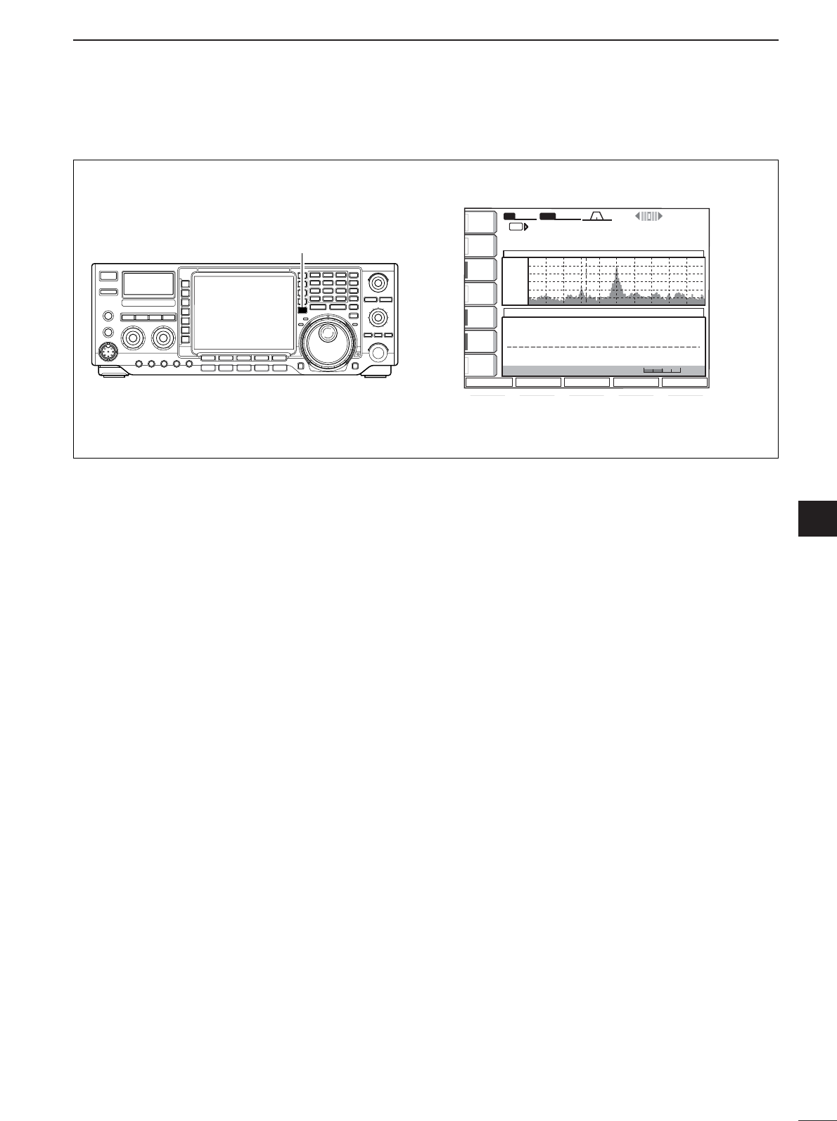
56
4
FUNCTION FOR RECEIVE
5
DMini scope screen
This mini scope screen can be displayed with another
screen indication, such as set mmode menu, decoder
screen, memory list screen, etc. simultaneously.
qPush [MAIN/SUB M.SCOPE] for 1 sec. to toggle
the mini scope indication ON and OFF.
**** RTTY Encode/Decode Monitor **** **** RTTY Encode/Decode Monitor ****
45bps BAUDOT Mark=2125Hz, Shift=170Hz 45bps BAUDOT Mark=2125Hz, Shift=170Hz
Max.62 Charascters x 8ch TX Memory Max.62 Charascters x 8ch TX Memory
If RTTY-FIL is OFF, Please turn ON. If RTTY-FIL is OFF, Please turn ON.
ANTANT
1
METERMETER
PoPo
P.AMPP.AMP
1
ATTATT
OFFOFF
AGCAGC
MIDMID
RTTYRTTY
FILFIL
ONON
1/41/4
OFFOFF
RTTY DECODERTTY DECODE
BWBW 350350 SFTSFT 0
VFOVFO
VFOVFO
wq≥qpp≥pp
14.100.0014.100.00
RTTY RTTY FIL2FIL2
SSBSSB FIL2FIL2
TXTX
THRESHOLDTHRESHOLD 9 9
<MENU1><MENU1> HLD/CLRHLD/CLR
TX MEMTX MEM ADJADJ WIDEWIDE
qw:pp
12:0012:00
Grid
2.5k
10dB
+ 12.5k
- 12.5k SPECTRUM SCOPE
[M.SCOPE]
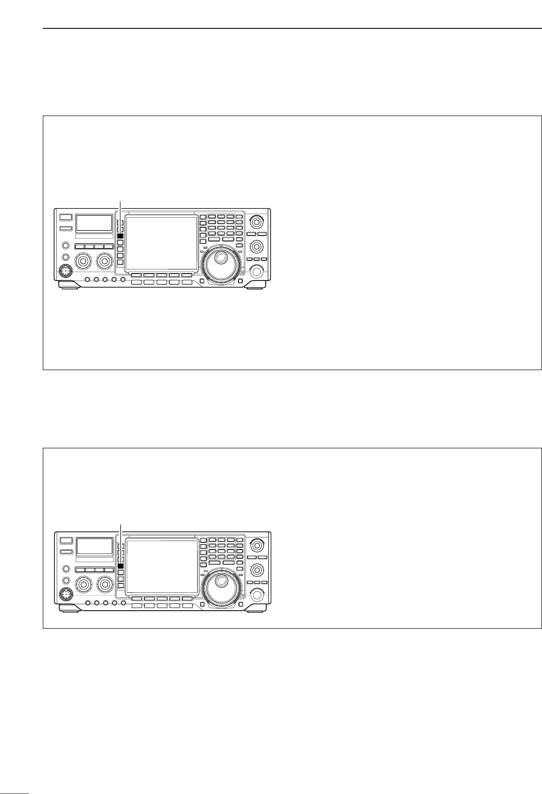
57
5FUNCTION FOR RECEIVE
■Preamp
The preamp amplifies received signals in the front
end circuit to improve the S/N ratio and sensitivity. Set
this to preamp 1 or preamp 2 when receiving weak
signals.
➥Push [P.AMP] several times to set the preamp OFF,
preamp 1 ON or preamp2 ON.
•“P. AMP1” activates 10 dB preamp for HF all bands.
•“P. AMP2” activates 16 dB high-gain preamp for
24 MHz band and above.
Regarding the use of the “P.AMP 2”
(Pre-amplifier 2)
The “P.AMP 2” is a high gain receive amplifier. When
the “P.AMP 2” is used during times of strong electric
fields, distortion sometimes results. In such cases,
use the transceiver with the “P.AMP 1” or “P.AMP
OFF” setting.
The “P.AMP 2” is most effective when:
•Used on bands above 24 MHz and when electric
fields are weak.
•Receive sensitivity is insufficient during low gain, or
while using a narrow band antenna (such as small
loop, a Beverage antenna or a short Yagi antenna,
etc.) is used.
[P.AMP]
■Attenuator
The attenuator prevents a desired signal from distor-
tion when very strong signals are near the desired fre-
quency or when very strong electric fields, such as
from broardcasting stations, are near your location.
➥Push [ATT] several times to set the attenuator 6
dB, 12 dB, 18 dB or OFF.
•“ATT 6dB,” “ATT 12dB,” “ATT 18dB” and “ATT OFF”
appears respectively.
[ATT]
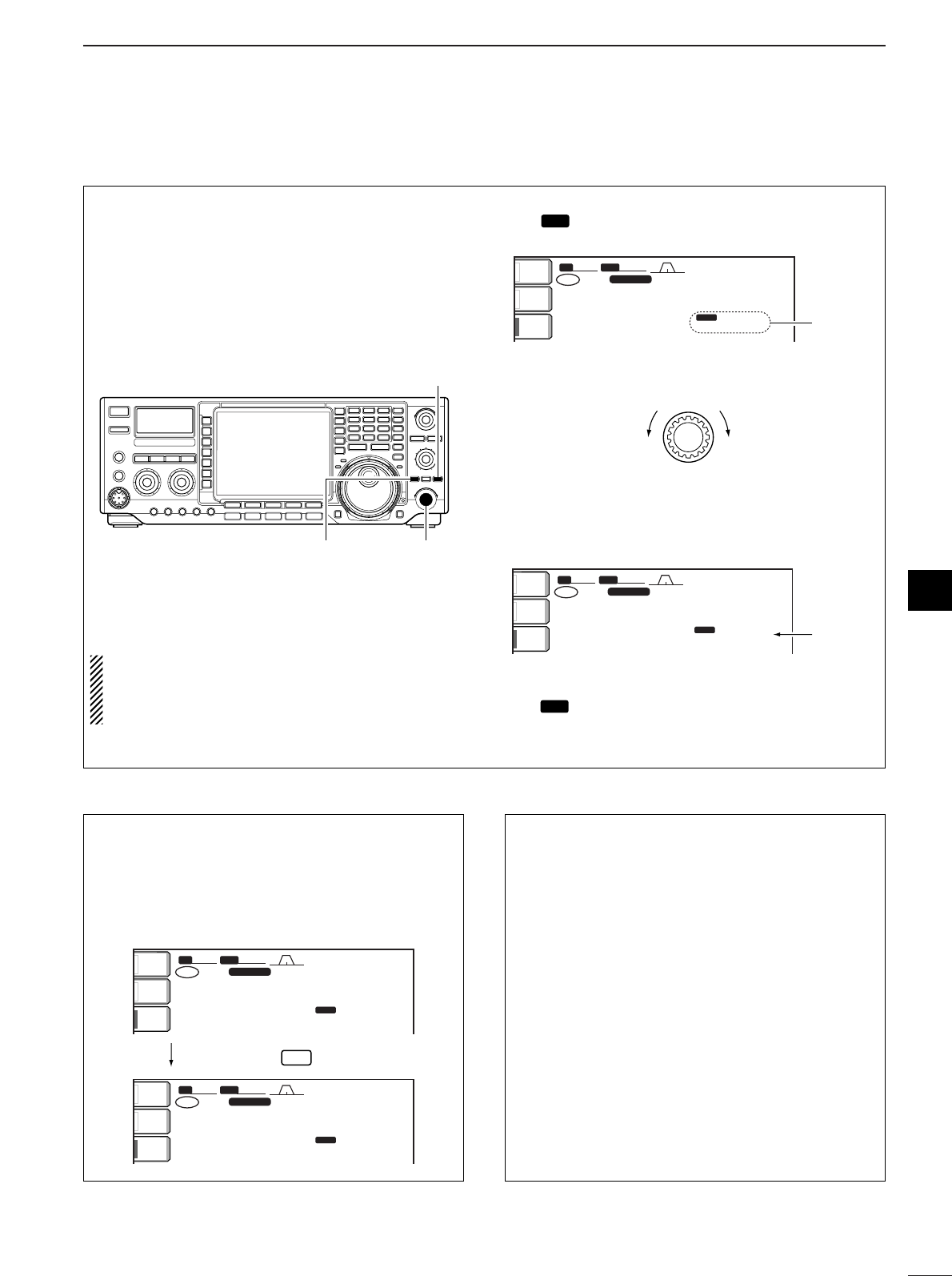
58
5
FUNCTION FOR RECEIVE
5
■RIT function
The RIT (Receive Increment Tuning) function com-
pensates for off-frequencies of the communicating
station.
The function shifts the receive frequency up to ±9.999
kHz in 1 Hz steps (10 Hz steps when cancelling the 1
Hz step readout) without moving the transmit fre-
quency.
•See @9 on p. 5 for function description.
qPush [RIT] to turn the RIT function ON and OFF.
•“ ” and the shifting frequency appear when the
function is ON.
wRotate the [RIT/∂TX] control.
eTo reset the RIT frequency, push [CLEAR] for
1sec.
•Push [CLEAR] momentarily to reset the RIT frequency
when the quick RIT/∂TX clear function is ON. (p. 102
rTo cancel the RIT function, push [RIT] again.
•“ ” disappears.
RIT
RIT
BW
BW
2.4k
2.4k
SFT
SFT
0
FIL2
FIL2
USB
USB
qw:pp
TX
TX
USB
USB
qr.qot.pp
14.100.00
14.100.00
p.pp
RIT
1
VFO
VFO
ANT
ANT
1
METER
METER
Po
Po
P.AMP
P.AMP
1
Reset to
“0.00”
RIT/∂TX
Low shift High shift
BW
BW
2.4k
2.4k
SFT
SFT
0
FIL2
FIL2
USB
USB
qw:pp
TX
TX
USB
USB
qr.qot.pp
14.100.00
14.100.00
q.wt
RIT
1
VFO
VFO
ANT
ANT
1
METER
METER
Po
Po
P.AMP
P.AMP
1Appear
RIT
RIT
[CLEAR]
[RIT/∂TX][RIT]
When RIT and ∂TX are ON at the same time, the
[RIT/∂TX] control shifts both the transmit and re-
ceive frequencies from the displayed frequency at
the same time.
•Calculate function
The shift frequency of the RIT or ∂TX function can
be added/subtracted to the displayed frequency.
While displaying the RIT and/or ∂TX shift frequency,
push [RIT] or [∂TX] for 1 sec.
•Practical example
When you find a DX station on 21.025 MHz/CW and
the station is picking up stations transmitting slightly
up from 21.025 MHz.
qPush [RIT] and [∂TX] to turn both the RIT and
∂TX functions ON.
wRotate [RIT/∂TX] to find the DX station’s receive
frequency.
eWhen you find the DX station’s receive frequency,
push [RIT] to turn the RIT function OFF.
•Now you can transmit the DX station’s receive fre-
quency and receive the DX station’s transmit fre-
quency (21.025 MHz).
rStart transmitting while the station is standing by.
BWBW 2.4k2.4k SFTSFT 0
FIL2FIL2
USBUSB
qw:pp
TXTX
USBUSB
qr.qot.pp
14.100.0014.100.00
p.wt
RIT
BWBW 2.4k2.4k SFTSFT 0
FIL2FIL2
USBUSB
qw:pp
TXTX
USBUSB
qr.qot.wt
14.100.0014.100.00
p.pp
RIT
1
VFOVFO
1
VFOVFO
ANTANT
1
METERMETER
PoPo
P.AMPP.AMP
1
ANTANT
1
METERMETER
PoPo
P.AMPP.AMP
1
Push and hold RIT
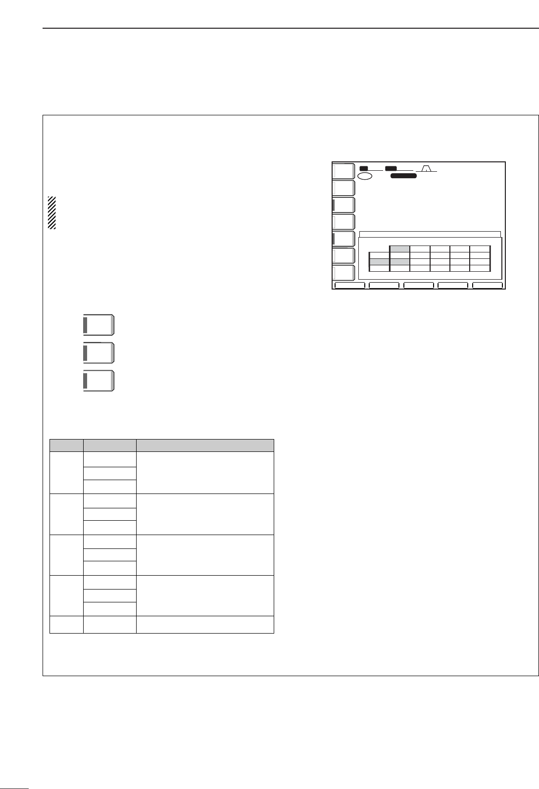
59
5FUNCTION FOR RECEIVE
■AGC function
The AGC (auto gain control) controls receiver gain to
produce a constant audio output level even when the
received signal strength is varied by fading, etc.
The transceiver has 3 AGC characteristics (time con-
stant; fast, mid, slow) for non-FM mode.
The FM mode AGC time constant is fixed as
‘FAST’ (0.1 sec.) and AGC time constant cannot be
selected.
•AGC time constant selection
qSelect non-FM mode.
wPush [AGC] several times to select AGC fast, AGC
medium (MID) or AGC slow.
•Selectable AGC time constant (unit: sec.)
•Setting the AGC time constant
qSelect the desired mode except FM mode.
wPush [AGC] for 1 sec. to enter AGC set mode.
ePush [AGC] several times to select FAST time
constant.
rRotate the tuning dial to set the desired time con-
stant for ‘AGC FAST.’
•AGC time constant can be set between 0.1 to 8.0 sec.
(depends on mode) or turned OFF.
•Push [(F-3)DEF] to select a default value.
tPush [AGC] to select medium time constant.
yRotate the tuning dial to set the desired time con-
stant for ‘AGC MID.’
•AGC time constant can be set between 0.1 to 8.0 sec.
(depends on mode) or turned OFF.
•Push [(F-3)DEF] to select a default value.
uPush [AGC] to select slow time constant.
iRotate the tuning dial to set the desired time con-
stant for ‘AGC SLOW.’
•AGC time constant can be set between 0.1 to 8.0 sec.
(depends on mode) or turned OFF.
•Push [(F-3)DEF] to select a default value.
oSelect another mode except FM. Repeat steps e
to iif desired.
!0 Push [EXIT/SET] to exit the AGC set mode screen.
DEFDEF
SFTSFT 0
FIL2FIL2
USBUSB
qw:pp
TXTX
VFOVFO USBUSB
USBUSB
USBUSB
FIL2FIL2
qr.qot.pp
qr.wpt.pp
14.100.0014.100.00
14.100.0014.100.00
1
1
VFOVFO
BWBW 2.4k2.4k
AGCAGC
(sec)(sec)
FMFM
AMAM
0.10.1
3.03.0
5.05.0
7.07.0
1.21.2
0.50.5
0.10.1
0.10.1
0.30.3
2.02.0
6.06.0
0.50.5
1.21.2
------
------
SSBSSB
FASTFAST
SLOWSLOW
MIDMID
CWCW RTTYRTTY
ANTANT
1
COMPCOMP
OFFOFF
WIDEWIDE
METERMETER
PoPo
P.AMPP.AMP
1
AGCAGC
MIDMID
ATTATT
OFFOFF
VOXVOX
OFFOFF
Medium AGC time constant
Slow AGC time constant
Fast AGC time constant
AGC
MID
AGC
SLOW
AGC
FAST
Mode Default Selectable AGC time constant
0.3 (FAST) OFF, 0.1, 0.2, 0.3, 0.5, 0.8, 1.2,
SSB 2.0 (MID) 1.6, 2.0, 2.5, 3.0, 4.0, 5.0, 6.0
6.0 (SLOW)
0.1 (FAST) OFF, 0.1, 0.2, 0.3, 0.5, 0.8, 1.2,
CW 0.5 (MID) 1.6, 2.0, 2.5, 3.0, 4.0, 5.0, 6.0
1.2 (SLOW)
0.1 (FAST) OFF, 0.1, 0.2, 0.3, 0.5, 0.8, 1.2,
RTTY 0.5 (MID) 1.6, 2.0, 2.5, 3.0, 4.0, 5.0, 6.0
1.2 (SLOW)
3.0 (FAST) OFF, 0.3, 0.5, 0.8, 1.2, 1.6, 2.0,
AM 5.0 (MID) 2.5, 3.0, 4.0, 5.0, 6.0, 7.0, 8.0
7.0 (SLOW)
FM 0.1 (FAST) Fixed
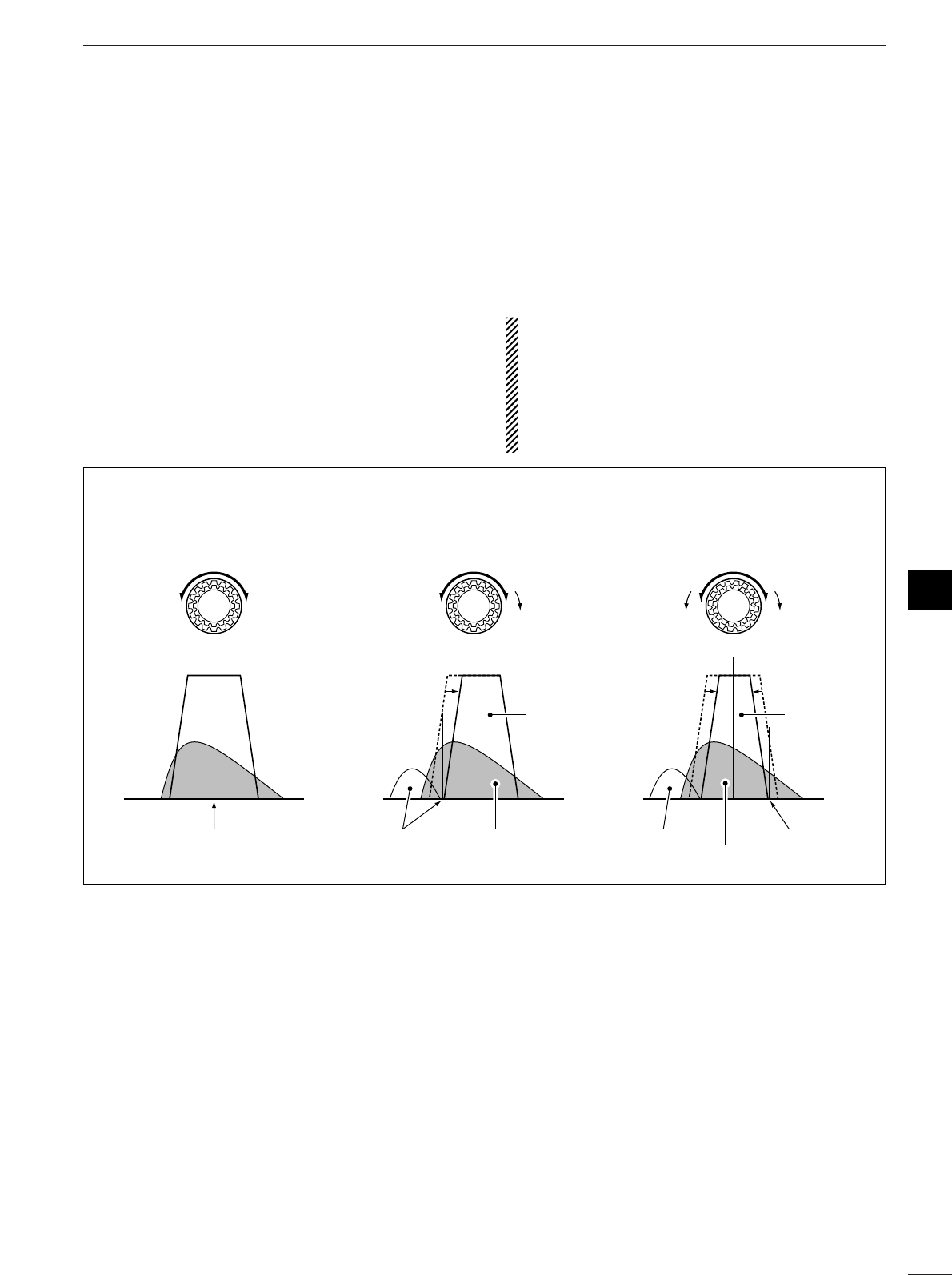
60
5
FUNCTION FOR RECEIVE
5
■Twin PBT operation
General PBT (Passband Tuning) function electronically
narrows the IF passband width by shifting the IF fre-
quency to slightly outside of the IF filter passband to
reject interference. This transceiver uses the DSP cir-
cuit for the PBT function. Moving both [TWIN PBT]
controls to the same position shifts the IF.
➥The LCD shows the passband width and shift fre-
quency graphically.
➥Push [FILTER] for 1 sec. to enter the filter set mode.
Current passband width and shift frequency is dis-
played in the filter set mode screen.
➥To set the [TWIN PBT] controls to the center posi-
tions, push [PBT CLR] for 1 sec.
The variable range depends on the passband width
and mode. The edge of the variable range is half of the
passband width, and PBT is adjustable in 25 or 50 Hz
steps. These controls function as an IF shift control
while in AM mode and when the RTTY filter is turned
ON. Only the inner control may function in this case.
IF shift is adjustable in 20/40 Hz steps in RTTY (RTTY
filter is turned ON) or 150/300/500 Hz steps in AM.
•[TWIN PBT] should normally be set to the center posi-
tions (PBT setting is cleared) when there is no interfer-
ence.
•When PBT is used, the audio tone may be changed.
•Not available for FM mode.
•While rotating [TWIN PBT], noise may occur. This comes
from the DSP unit and does not indicate an equipment
malfunction.
PBT OPERATION EXAMPLE
TWIN PBT TWIN PBT
TWIN PBT
IF center frequency Interference Desired signal
Passband
Both controls at
center position Cutting a lower
passband Cutting both higher and
lower passbands
Interference Interference
Desired signal
Passband
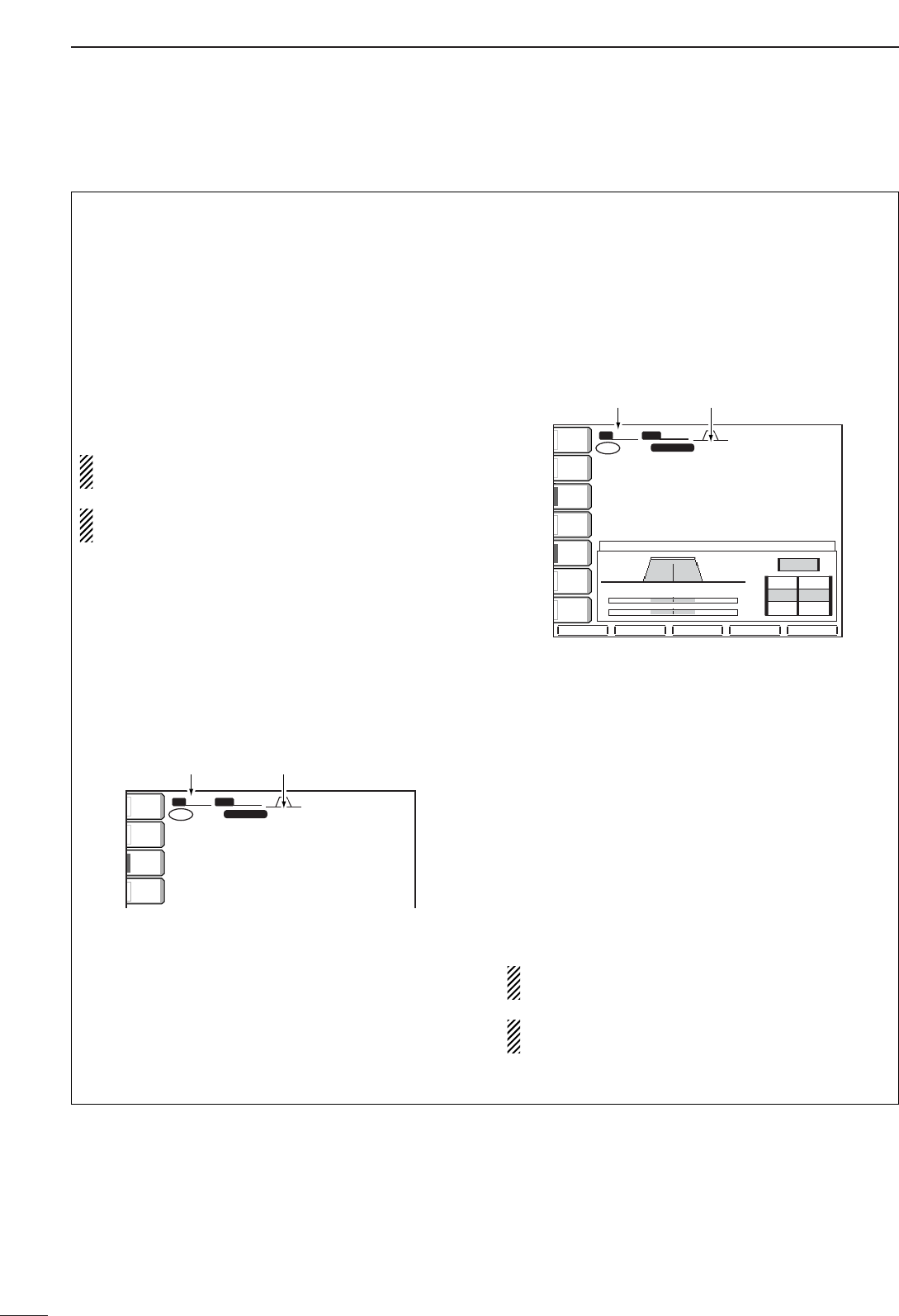
61
5FUNCTION FOR RECEIVE
■IF filter selection
The transceiver has 3 passband width IF filters for
each mode.
For SSB and CW modes, the passband width can be
set within 50 to 3600 Hz in 50 or 100 Hz steps. A total
of 41 passband widths are available.
For RTTY mode, the passband width can be set
within 50 to 2700 Hz in 50 or 100 Hz steps. A total of
32 passband widths are available.
For AM and FM modes, the passband width is fixed
and 3 passband widths are available.
The filter selection is automatically memorized in
each mode.
The PBT shift frequencies are automatically mem-
orized in each filter.
•IF filter selection
qSelect the desired mode.
wFor RTTY mode, turn OFF the RTTY filter by push-
ing [RTTY FIL].
ePush [FILTER] several times to select the IF filter
1, 2 or 3.
•The selected passband width and filter number is dis-
played in the LCD.
•Filter passband width setting
(SSB, CW and RTTY mode only)
qSelect SSB, CW or RTTY mode.
•Passband widths for AM and FM modes are fixed and
cannot be set.
wFor RTTY mode, turn OFF the RTTY filter by push-
ing [RTTY FIL].
ePush [FILTER] for 1 sec. to enter filter set mode.
rPush [FILTER] several times to select the desired
IF filter.
tWhile pushing [(F-1)BW], rotate the tuning dial to
set the desired passband width.
•In SSB and CW modes, the passband width can be set
within the following range.
50 to 500 Hz 50 Hz steps
600 to 3600 Hz 100 Hz steps
•In RTTY mode, the passband width can be set within
the following range.
50 to 500 Hz 50 Hz steps
600 to 2700 Hz 100 Hz steps
•Push [(F-3)DEF] to select the default value.
yRepeat steps rto tif desired.
uPush [EXIT/SET] to exit the filter set mode screen.
The PBT shift frequencies are cleared when the
passband width is changed.
This filter set mode screen graphically displays the
PBT shift frequencies and CW pitch operations.
BW
BW
DEF
DEF
SFT
SFT
0
FIL2
FIL2
USB
USB
qw:pp
TX
TX
VFO
VFO
USB
USB
USB
USB
USB
USB
FIL2
FIL2
qr.qot.pp
qr.wpt.pp
14.100.00
14.100.00
14.100.00
14.100.00
1
1
VFO
VFO
BW
BW
2.4k
2.4k
FILTER
FILTER
SSB
SSB
FI
FI
L 1
FI
FI
L 2
FI
FI
L 3
3.0k
3.0k
2.4K
2.4K
1.8K
1.8K
PBT2
PBT2
PBT1
PBT1
300
300
1500
1500
2700
2700
ANT
ANT
1
COMP
COMP
OFF
OFF
WIDE
WIDE
METER
METER
Po
P.AMP
P.AMP
1
AGC
AGC
MID
MID
ATT
ATT
OFF
OFF
VOX
VOX
OFF
OFF
Passband
width Selected
IF filter
SFT
SFT
0
FIL2
FIL2
USB
USB
qw:pp
TX
TX
VFO
VFO
USB
USB
USB
USB
USB
USB
FIL2
FIL2
qr.qot.pp
qr.wpt.pp
14.100.00
14.100.00
14.100.00
14.100.00
1
1
VFO
VFO
BW
BW
2.4k
2.4k
ANT
ANT
1
METER
METER
Po
Po
P.AMP
P.AMP
1
ATT
ATT
OFF
OFF
Passband
width Selected
IF filter
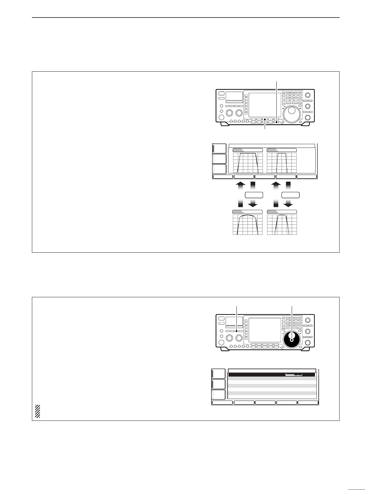
62
5
FUNCTION FOR RECEIVE
■DSP filter shape
The type of DSP filter shape for each SSB and CW
can be selected independently from soft and sharp.
qPush the [EXIT/SET] several times to close a
multi-function screen, if necessary.
wPush the [EXIT/SET] switch for 1 sec. to enter set
mode.
ePush the [(F-3)DSP] switch to enter the DSP filter
set mode.
rPush one of [(F2)SSB-FIL] or [(F4)CW-FIL] to se-
lect the desired DSP filter shape from sharp and
soft for each SSB or CW mode, respectively.
tPush the [ENTER/SET] twice to exit the set mode.
[EXIT/SET] switch
[(F-3)DSP] switch
AGCAGC
MIDMID
BK-INBK-IN
OFFOFF
1/41/4
OFFOFF
DSP FILTER SET
SSBSSB SHARPSHARP CWCW SHARPSHARP
SSB-FILSSB-FIL CW-FILCW-FIL
SSBSSB SOFTSOFT CWCW SOFTSOFT
F-4
Push
F-2
Push
■Noise blanker
The noise blanker eliminates pulse-type noise such
as from car ignitions. The noise blanker is not avail-
able for FM mode.
qPush the [NB] switch to turn the noise blanker ON.
•[NB] indicator lights.
wPush the [NB] switch for 1 sec. to enter the noise
blanker level set mode.
eRotate the tuning dial to adjust the noise blanker
level.
•Push [(F-3)DEF] for 1 sec. to return to default value.
rPush the [NB] switch to turn the noise blanker
OFF.
•[NB] indicator goes off.
When using the noise blanker, received signals
may be distorted if they are excessively strong.
[NB] switch Tuning dial
VOX
VOX
ON
ON
COMP
COMP
OFF
OFF
WIDE
WIDE
AGC
AGC
MID
MID
NB
NB
NB Level
NB Level
50%
50%
DEF
DEF
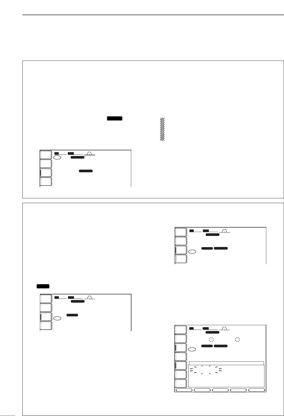
63
5FUNCTION FOR RECEIVE
■Dualwatch operation
Dualwatch monitors 2 frequencies with the same
mode simultaneously.
During dualwatch, both frequencies should be on the
same band, because the bandpass filter in the RF cir-
cuit is selected for the main readout frequency.
qSet a desired frequency.
wPush [DUALWATCH] for 1 sec.
•Equalized receive frequency and “ ” appear in
the LCD. This quick dualwatch function can be turned
OFF in set mode. (p. 98)
•Pushing [DUALWATCH] momentarily activates the du-
alwatch with the previously operated frequency.
eSet another desired frequency using the tuning
dial.
rAdjust [BAL] to set a suitable signal strength bal-
ance between the main and sub readout frequen-
cies.
•S-meter shows the combined signal strength.
tTo transmit on the sub readout frequency, push
[CHANGE] or [SPLIT].
RIT function can be used for the main readout only.
∂TX function can be used for the transmit readout
(main readout when the split function is OFF; sub
readout when the split function is ON).
BW
BW
2.4k
2.4k
SFT
SFT
0
FIL2
FIL2
USB
USB
qw:pp
VFO
VFO
TX
TX
56
56
1
USB
USB
USB
USB
USB
USB
FIL2
FIL2
wq.wop.pp
wq.wop.pp
14.100.00
14.100.00
14.100.00
14.100.00
VFO
VFO
DUAL-W
DUAL-W
ANT
ANT
1
METER
METER
Po
Po
P.AMP
P.AMP
1
ATT
ATT
OFF
OFF
DUAL-W
DUAL-W
•Scanning during dualwatch
Scanning operates only for the main readout. To op-
erate the scan during dualwatch, scan on the main
readout and use the sub readout for your QSO using
both dualwatch and split frequency operation.
qProgram the desired programmed scan edges in
the same amateur band. See p. 78 for program-
ming.
•If you plan to operate a ∂F scan, programming the
scan edges may not be necessary.
wPush [SPLIT] to turn the split frequency function
ON.
•“ ” appears.
eSelect VFO mode for the main readout.
rSet the desired operating frequency for the main
readout.
tPush [DUALWATCH] for 1 sec.
•The main and sub readout frequencies are equalized
and the dualwatch function is turned ON.
yPush [(F-4)SCAN] to select the scan screen.
•Push [EXIT/SET] several times to close a multi-func-
tion screen, if necessary.
uPush [(F-1)PROG] or [(F-2)∂F] to start the pro-
grammed scan or ∂F scan, respectively.
•Scan activates on the main readout between the pro-
grammed scan edges or within the ∂F span.
•Transmitting on the sub readout stops the scan.
iTo cancel the scan, push [EXIT/SET].
wq.wop.pp
BWBW 2.4k2.4k SFTSFT 0
FIL2FIL2
USBUSB
qw:pp
VFOVFO USBUSB
USBUSB
USBUSB
FIL2FIL2
wq.wtp.pp
14.100.0014.100.00
14.100.0014.100.00
VFOVFO
SPLITSPLIT
1
1
DUAL-WDUAL-W
PROGPROG ∂FFINEFINE ∂F SPANF SPAN SETSET
SCANSCAN
TXTX
ANTANT
1
COMPCOMP
OFFOFF
WIDEWIDE
METERMETER
PoPo
P.AMPP.AMP
1
AGCAGC
MIDMID
ATTATT
OFFOFF
VOXVOX
OFFOFF
PROGRAM SCANPROGRAM SCAN
∂FSpanSpan:±±10kHz10kHz
ProgrammedProgrammedP1:P1:21.000.00MHz21.000.00MHz
scanscanedgesedgesP2:P2:21.450.00MHz21.450.00MHz
wq.wop.pp
BWBW 2.4k2.4k SFTSFT 0
FIL2FIL2
USBUSB
qw:pp
VFOVFO USBUSB
USBUSB
USBUSB
FIL2FIL2
wq.wop.pp
14.100.0014.100.00
14.100.0014.100.00
VFOVFO
SPLITSPLIT
1
1
DUAL-WDUAL-W
TXTX
ANTANT
1
METERMETER
PoPo
P.AMPP.AMP
1
ATTATT
OFFOFF
BWBW 2.4k2.4k SFTSFT 0
FIL2FIL2
USBUSB
qw:pp
VFOVFO USBUSB
USBUSB
USBUSB
FIL2FIL2
wq.wop.pp
14.100.0014.100.00
14.100.0014.100.00
VFOVFO
qr.wpt.pp
SPLITSPLIT
1
1
TXTX
ANTANT
1
METERMETER
PoPo
P.AMPP.AMP
1
ATTATT
OFFOFF
SPLIT
SPLIT
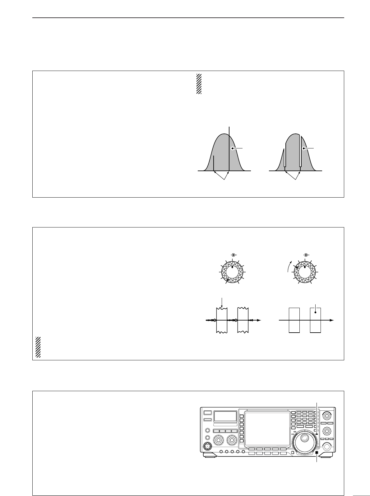
64
5
FUNCTION FOR RECEIVE
■Notch function
This transceiver has auto and manual notch func-
tions. The auto notch function automatically attenu-
ates more than 3 beat tones, tuning signals, etc.,
even if they are moving. The manual notch can be set
to attenuate a frequency via the [NOTCH] control.
➥Push [NOTCH] to toggle the notch function be-
tween auto, manual and OFF in SSB and AM
modes.
➥Push [NOTCH] to turn the manual notch function
ON and OFF in CW mode.
➥Push [NOTCH] to turn the auto notch function ON
and OFF in FM mode.
•Set to attenuate a frequency for manual notch via the
[NOTCH] control.
•“AN” appears when auto notch is in use.
•“MN” appears when manual notch is in use.
While operating the manual notch, noise may be
heard. This comes from the DSP unit and does not
indicate an equipment malfunction.
Unwanted tone
frequency
Desired
signal (AF) Desired
signal (AF)
Particular frequency
is attenuated
Auto notch OFF Auto notch ON
■Noise reduction
The noise reduction function reduces noise compo-
nents and picks out desired signals which are buried
in noise. The received signals are converted to digital
signals and then the desired signals are separated
from the noise.
qPush the [NR] switch to turn the noise reduction
ON.
•[NR] indicator lights.
wRotate the [NR] control to adjust the noise reduc-
tion level.
ePush the [NR] switch to turn the noise reduction
OFF.
•[NR] indicator lights off.
Deep rotation of the [NR] control results in audio
signal masking or distortion. Set the [NR] control
for maximum readability.
BAL NR
Noise reduction OFF Noise reduction activated
Desired
signal (CW)
Noise components
BAL NR
■Dial lock function
The dial lock function prevents changes by accidental
movement of the tuning dial. The lock function elec-
tronically locks the dial.
➥Push [LOCK/SPEECH] to toggle the dial lock func-
tion ON and OFF.
•The [LOCK] indicator lights when the dial lock function
is in use.
[LOCK] indicator
[LOCK/SPEECH] switch
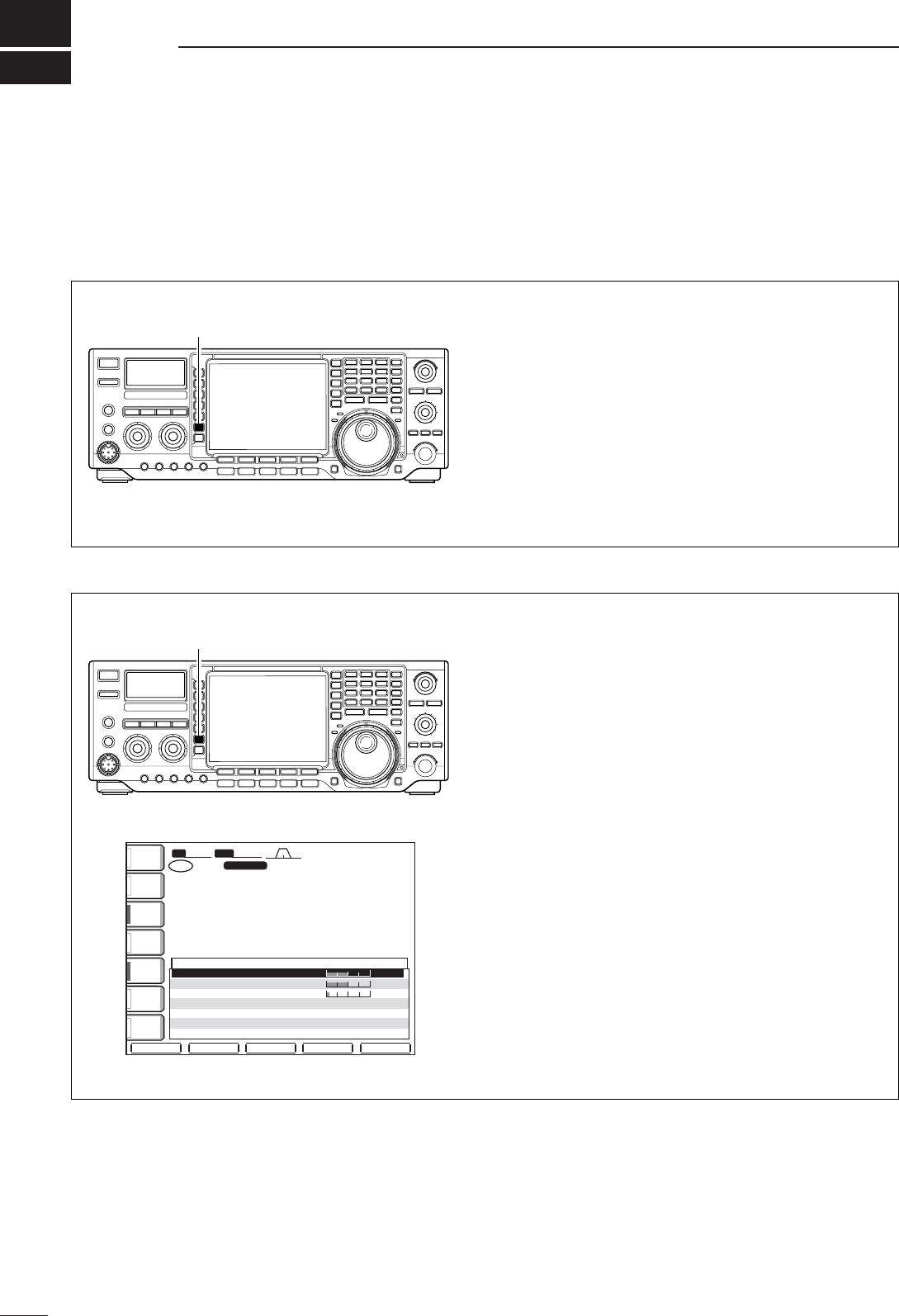
6
65
FUNCTION FOR TRANSMIT
■VOX function
DDUsing the VOX function
qSelect a phone mode (SSB, AM, FM).
wPush [VOX] to turn the VOX function ON or OFF.
•“VOX ON” appears while the VOX is in use.
[VOX]
DDAdjusting the VOX function
qSelect a phone mode (SSB, AM, FM).
wPush [VOX] to turn VOX function ON.
ePush [VOX] for 1 sec. to enter VOX set mode.
rSelect the VOX gain item using [(F-1)Y] or [(F-
2)Z].
tWhile speaking into the microphone, rotate the
tuning dial to the point where the transceiver is
continuously transmitting.
yAdjust the VOX delay for a convenient interval be-
fore returning to receive.
-Select the VOX delay item using [(F-1)Y] or [(F-2)Z].
-Rotate the tuning dial.
uIf the receive audio from the speaker switches to
transmit, adjust the anti VOX to the point where it
has no effect.
BWBW 2.4k2.4k SFTSFT 0
FIL2FIL2
USBUSB
qw:pp
TXTX
VFOVFO USBUSB
USBUSB
USBUSB
FIL2FIL2
qr.qot.pp
qr.wpt.pp
14.100.0014.100.00
14.100.0014.100.00
1
1
VFOVFO
éèDEF
VOX
ANTANT
1
COMPCOMP
OFFOFF
WIDEWIDE
METERMETER
PoPo
P.AMPP.AMP
1
AGCAGC
MIDMID
ATTATT
OFFOFF
VOXVOX
OFFOFF
VOXGain 50%
Anti-VOX 50%
VOXDelay 0.2s
[VOX]
The VOX (Voice-Operated Transmission) function
switches between transmit and receive with your voice.
This function provides an opportunity to input log en-
tries into your computer, etc., while operating.
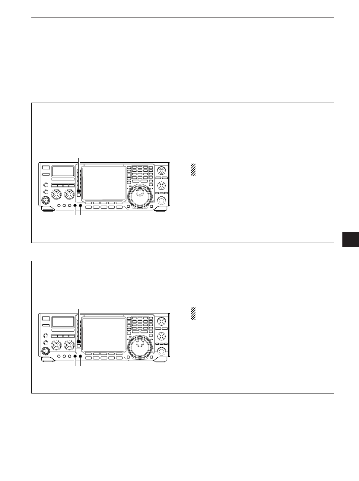
66
6
FUNCTION FOR TRANSMIT
6
■Break-in function
DDSemi break-in operation
During semi break-in operation, the transceiver se-
lects transmit when keying, then automatically returns
to receive after a pre-set time from when you stop
keying.
qPush [CW] to select CW or CW-R mode.
wPush [BK-IN] several times to turn the semi break-
in function ON.
•“BK-IN SEMI” appears.
eRotate [BK-IN DELAY] to set the break-in delay
time (the delay from transmit to receive).
When using a paddle, rotate [KEY SPEED] to ad-
just the keying speed.
[BK-IN]
[BK-IN DELAY] [KEY SPEED]
DDFull break-in operation
During full break-in operation, the transceiver auto-
matically selects transmit while keying and returns to
receive immediately after keying is finished.
qPush [CW] to select CW or CW-R mode.
wPush [BK-IN] several times to turn the full break-in
function ON.
•“BK-IN FULL” appears.
When using a paddle, rotate [KEY SPEED] to ad-
just the keying speed.
[BK-IN]
[BK-IN DELAY] [KEY SPEED]
The break-in function is used in CW mode to automat-
ically toggle the transceiver between transmit and re-
ceive when keying. The IC-756PROIII is capable for
full break-in or semi break-in.
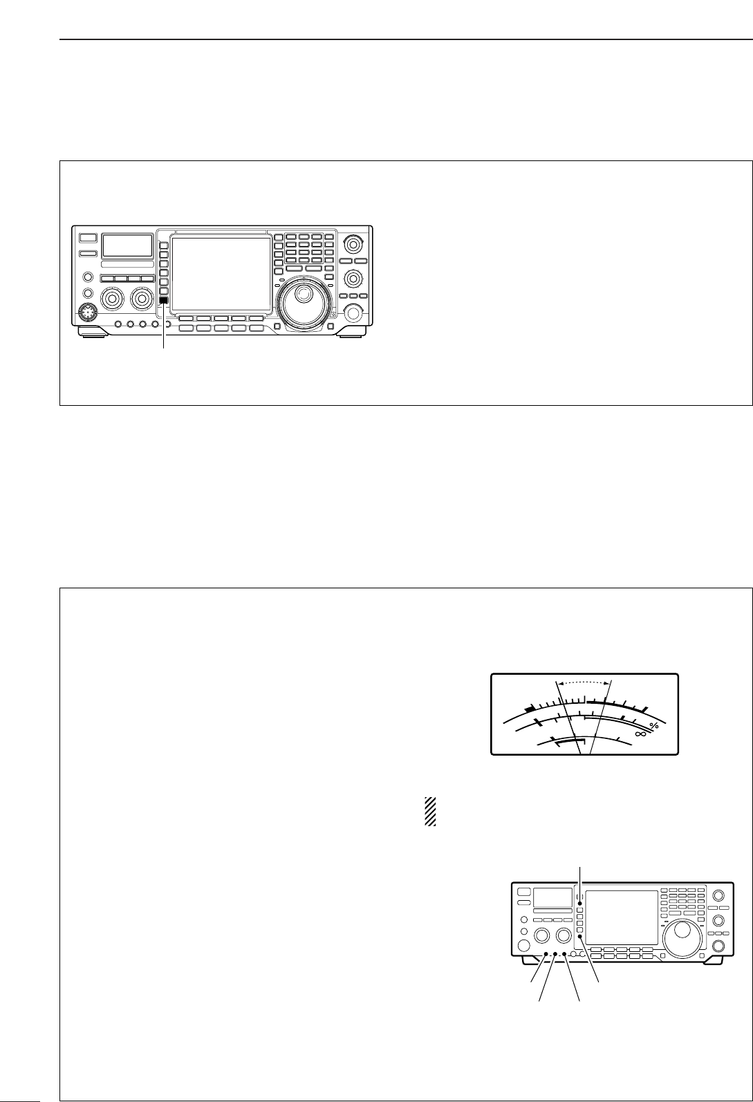
67
6FUNCTION FOR TRANSMIT
■Transmit filter width setting (SSB only)
The transmit filter width for SSB mode can be se-
lected from wide, middle and narrow.
➥During USB or LSB mode selection, push [COMP]
for 1 sec. several times to select the desired trans-
mit filter width from wide, middle and narrow.
•The filter functions regardless of the speech compres-
sor use.
•The following filters are specified as the default. Each
of the filter width can be re-set in level set mode.
(pgs. 93, 94)
WIDE : 100 Hz to 2.9 kHz
MID : 300 Hz to 2.7 kHz
NAR : 500 Hz to 2.5 kHz
[COMP]
■Speech compressor
The RF speech compressor increases average RF
output power, improving signal strength and readabil-
ity in SSB.
•Speech compressor
qSelect USB or LSB mode.
wPush [COMP] momentarily to turn the speech
compressor ON and OFF.
ePush [COMP] for 1 sec. to toggle between narrow,
middle or wide transmit filter.
•Transmit filter width:
NAR 2.0 kHz
MID 2.6 kHz
WIDE 2.9 kHz
•Compression level setting
qSelect USB or LSB mode.
wPreset the transceiver as follows:
[COMP] function : OFF
[METER] function : ALC
[MIC GAIN] control : Center position
[COMP] control : Center position
[RF POWER] control : Max. counterclockwise
eTransmit at your normal voice level.
rAdjust the [MIC GAIN] control so that the ALC
meter reads within the ALC zone, whether or not
you speak softly or loudly.
tPush [COMP] momentarily to turn the speech
compressor ON.
yPush [METER] once to select the COMP meter.
uAdjust the [COMP] control so that the COMP
meter reads within 10 dB and 20 dB.
When the ALC meter peaks above the ALC zone,
your transmitted voice may be distorted.
[METER] switch
[COMP] switch[MIC GAIN] control
[COMP] control[RF POWER] control
SWR
S
COMP
ALC
Po
010
10
25 50 100
20
101.5 23
159+20 +40 +60dB
dB
COMP meter
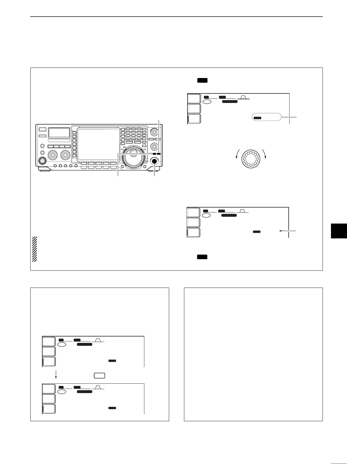
68
6
FUNCTION FOR TRANSMIT
6
■∂∂TX function
The ∂TX function shifts the transmit frequency up to
±9.999 kHz in 1 Hz steps (10 Hz steps when can-
celling the 1 Hz step readout) without moving the re-
ceive frequency.
•See #0 on p. 5 for function description.
qPush [∂TX] switch.
•“ ” and the shifting frequency appear when the
function is ON.
wRotate the [RIT/∂TX] control.
eTo reset the ∂TX frequency, push [CLEAR] for
1sec.
•Push [CLEAR] momentarily to reset the RIT frequency
when the quick RIT/∂TX clear function is ON. (p. 102)
rTo cancel the ∂TX function, push [∂TX] again.
•“ ” and the shifting frequency disappears.
∂TX
TX
BW
BW
2.4k
2.4k
SFT
SFT
0
FIL2
FIL2
USB
USB
qw:pp
TX
TX
USB
USB
qr.qot.pp
14.100.00
14.100.00
p.pp
:TX
1
VFO
VFO
ANT
ANT
1
METER
METER
Po
Po
P.AMP
P.AMP
1
Reset to
“0.00”
RIT/∂TX
Low shift High shift
BW
BW
2.4k
2.4k
SFT
SFT
0
FIL2
FIL2
USB
USB
qw:pp
TX
TX
USB
USB
qr.qot.pp
14.100.00
14.100.00
q.wt
:TX
1
VFO
VFO
ANT
ANT
1
METER
METER
Po
Po
P.AMP
P.AMP
1Appear
∂TX
TX
[CLEAR]
[RIT/∂TX][∂TX]
When RIT and ∂TX are ON at the same time, the
[RIT/∂TX] control shifts both the transmit and re-
ceive frequencies from the displayed frequency at
the same time.
•Calculate function
The shift frequency of the RIT or ∂TX function can
be added/subtracted to the displayed frequency.
While displaying the RIT and/or ∂TX shift frequency,
push [RIT] or [∂TX] for 1 sec.
•Practical example
When you find a DX station on 21.025 MHz/CW and
the station is picking up stations transmitting slightly
up from 21.025 MHz.
qPush [RIT] and [∂TX] to turn both the RIT and
∂TX functions ON.
wRotate [RIT/∂TX] to find the DX station’s receive
frequency.
eWhen you find the DX station’s receive frequency,
push [RIT] to turn the RIT function OFF.
•Now you can transmit the DX station’s receive fre-
quency and receive the DX station’s transmit fre-
quency (21.025 MHz).
rStart transmitting while the station is standing by.
BWBW 2.4k2.4k SFTSFT 0
FIL2FIL2
USBUSB
qw:pp
TXTX
USBUSB
qr.qot.pp
14.100.0014.100.00
p.wt
BWBW 2.4k2.4k SFTSFT 0
FIL2FIL2
USBUSB
qw:pp
TXTX
USBUSB
qr.qot.wt
14.100.0014.100.00
p.pp
1
VFOVFO
1
VFOVFO
ANTANT
1
METERMETER
PoPo
P.AMPP.AMP
1
ANTANT
1
METERMETER
PoPo
P.AMPP.AMP
1
:TX
:TX
Push and hold
∂TX
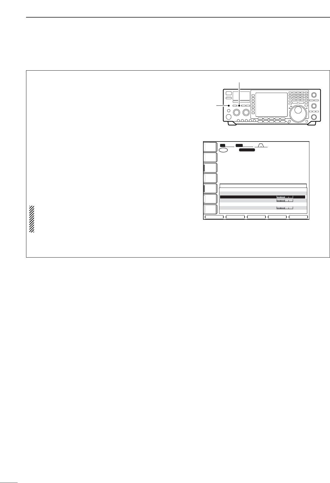
69
6FUNCTION FOR TRANSMIT
■Monitor function
The monitor function allows you to monitor your trans-
mit IF signals in any mode through the speaker. Use
this to check voice characteristics while adjusting
SSB transmit tones. (p. 93) The CW sidetone func-
tions regardless of the [MONITOR] switch setting.
qPush [MONITOR].
•The indicator lights when the monitor function is ON.
wPush [EXIT/SET] several times to close a multi-
function screen, if necessary.
ePush [EXIT/SET] for 1 sec. then [(F-1)LEVEL] to
enter level set mode.
rPush [(F-1)Y] or [(F-2)Z] to select the monitor
level item.
tAdjust monitor gain using the tuning dial.
•Pushing [(F-3)DEF] sets the selected item to the default
value of the item.
yPush [EXIT/SET] twice to exit level set mode.
•Use headphones to prevent feedback.
•Set the transmit tone settings to the 0 dB positions
to check the unaltered characteristics of transmit-
ter or microphone.
BWBW 2.4k2.4k SFTSFT 0
FIL2FIL2
USBUSB
qw:pp
TXTX
VFOVFO USBUSB
USBUSB
USBUSB
FIL2FIL2
qr.qot.pp
qr.wpt.pp
14.100.0014.100.00
14.100.0014.100.00
1
1
VFOVFO
éèDEF
LEVEL SET
ANTANT
1
COMPCOMP
OFFOFF
WIDEWIDE
METERMETER
PoPo
P.AMPP.AMP
1
AGCAGC
MIDMID
ATTATT
OFFOFF
VOXVOX
OFFOFF
SSBTBW(NAR) L500
SSBTBW(NAR) H2500
MonitorLevel 50%
SideToneLevel 50%
SideToneLevelLimit ON
BeepLevel 50%
BeepLevelLimit ON
[MONITOR] switch
[PHONES]
jack
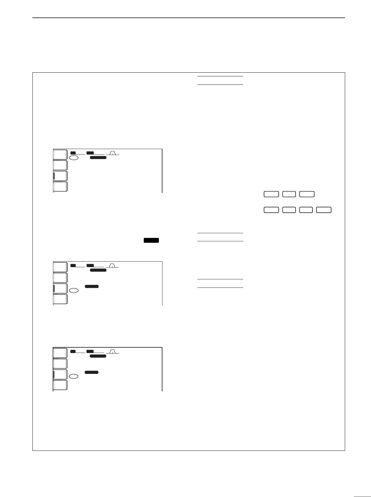
70
6
FUNCTION FOR TRANSMIT
■Split frequency operation
Split frequency operation allows you to transmit and
receive in the same mode on two different frequen-
cies. The split frequency operation is basically per-
formed using 2 frequencies on the main and sub
readouts.
The following is an example of setting 21.290 MHz for
receiving and 21.310 MHz for transmitting.
qSet 21.290 MHz (USB) in VFO mode.
wPush [SPLIT] momentarily, then push [CHANGE]
for 1 sec.
•The quick split function is much more convenient for
selecting the transmit frequency. See the next section
for details.
•The equalized transmit frequency and “ ” appear
on the LCD.
•“TX” appears to show the transmit frequency’s readout.
eRotate the tuning dial while pushing [XFC] to set
the transmit frequency to 21.310 MHz.
•The transmit frequency can be monitored while pushing
[XFC] or using dualwatch.
rNow you can receive on 21.290 MHz and transmit on
21.310 MHz.
To change the transmit and receive frequencies, push
[CHANGE] to exchange the main and sub readouts.
DIRECT SHIFT FREQUENCY INPUT
The shift frequency can be entered directly.
qPush [F-INP].
wEnter the desired shift frequency with the digit
keys.
•1 kHz to 1 MHz can be set.
•When you require a minus shift direction, push [ • ] in
advance.
ePush [SPLIT].
•The shift frequency is input in the sub readout and the
split function is turned ON.
[EXAMPLE]
DUALWATCH FUNCTION
The dualwatch function is convenient for tuning the
transmit frequency while monitoring both frequencies
used for transmitting and receiving.
SPLIT LOCK FUNCTION
Accidentally releasing the [XFC] switch while rotating
the tuning dial changes the receive frequency. To pre-
vent this, use both the split lock and dial lock func-
tions to change the transmit frequency only. The split
lock function cancels the dial lock function while push-
ing [XFC] during split frequency operation.
The dial lock’s effectiveness during split frequency op-
eration can be selected in the set mode for both re-
ceive and transmit frequencies; or only the receive
frequency. (p. 99)
CONVENIENT
CONVENIENT
•
1F-INP SPLIT
F-INP 3 SPLIT
To operate on 1 kHz
higher frequency:
To operate on 3 kHz
lower frequency:
CONVENIENT
BWBW 2.4k2.4k SFTSFT 0
FIL2FIL2
USBUSB
qw:pp
VFOVFO USBUSB
USBUSB
USBUSB
FIL2FIL2
wq.wop.pp
14.100.0014.100.00
14.100.0014.100.00
VFOVFO
wq.eqp.pp
1
1
SPLITSPLIT
TXTX
ANTANT
1
METERMETER
PoPo
P.AMPP.AMP
1
ATTATT
OFFOFF
BWBW 2.4k2.4k SFTSFT 0
FIL2FIL2
USBUSB
qw:pp
VFOVFO USBUSB
USBUSB
USBUSB
FIL2FIL2
wq.wop.pp
14.100.0014.100.00
14.100.0014.100.00
VFOVFO
wq.wop.pp
1
1
SPLITSPLIT
TXTX
ANTANT
1
METERMETER
PoPo
P.AMPP.AMP
1
ATTATT
OFFOFF
SPLIT
SPLIT
BW
BW
2.4k
2.4k
SFT
SFT
0
FIL2
FIL2
USB
USB
qw:pp
TX
TX
VFO
VFO
USB
USB
USB
USB
USB
USB
FIL2
FIL2
wq.wop.pp
14.100.00
14.100.00
14.100.00
14.100.00
VFO
VFO
qr.wpt.pp
1
1
ANT
ANT
1
METER
METER
Po
Po
P.AMP
P.AMP
1
ATT
ATT
OFF
OFF
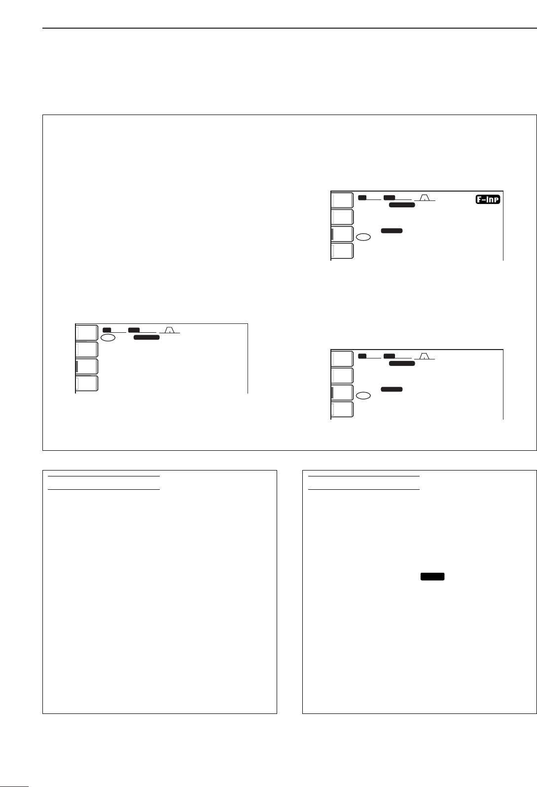
71
6FUNCTION FOR TRANSMIT
■Quick split function
When you find a DX station, an important considera-
tion is how to set the split frequency.
When you push the [SPLIT] switch for 1 sec., split fre-
quency operation is turned ON, the sub readout is
equalized to the main readout frequency and enters
standby for transmit frequency input.
This shortens the time needed to start split frequency
operation.
The quick split function is ON by default. For your
convenience, it can be turned OFF in set mode.
(p. 98) In this case, the [SPLIT] switch does not
equalize the main and sub readout frequencies.
qSuppose you are operating at 21.290 MHz (USB)
in VFO mode.
wPush [SPLIT] for 1 sec.
•Split frequency operation is turned ON.
•The sub readout is equalized to the main readout fre-
quency.
•The sub readout enters standby for transmit frequency
input.
eRotate the tuning dial to set the transmit fre-
quency; or, input the transmit frequency using the
keypad and [ENT]; or, input a shift frequency using
the keypad and [SPLIT].
•The transmit frequency can be monitored while pushing
[XFC] or using dualwatch.
BWBW 2.4k2.4k SFTSFT 0
FIL2FIL2
USBUSB
VFOVFO USBUSB
USBUSB
USBUSB
FIL2FIL2
wq.wop.pp
14.100.0014.100.00
14.100.0014.100.00
VFOVFO
wq.eqp.pp
1
1
SPLITSPLIT
TXTX
qw:pp
ANTANT
1
METERMETER
PoPo
P.AMPP.AMP
1
ATTATT
OFFOFF
BWBW 2.4k2.4k SFTSFT 0
FIL2FIL2
USBUSB
VFOVFO USBUSB
USBUSB
USBUSB
FIL2FIL2
wq.wop.pp
14.100.0014.100.00
14.100.0014.100.00
VFOVFO
wq.wop.pp
1
1
SPLITSPLIT
TXTX
ANTANT
1
METERMETER
PoPo
P.AMPP.AMP
1
ATTATT
OFFOFF
BWBW 2.4k2.4k SFTSFT 0
FIL2FIL2
USBUSB
qw:pp
TXTX
VFOVFO USBUSB
USBUSB
USBUSB
FIL2FIL2
wq.wop.pp
14.100.0014.100.00
14.100.0014.100.00
VFOVFO
qr.wpt.pp
1
1
ANTANT
1
METERMETER
PoPo
P.AMPP.AMP
1
ATTATT
OFFOFF
When you are searching for DX stations and you
suspect that a DX station may say “up ‘X’ kHz” for
their receive frequency:
OPERATION 1
qPush [SPLIT] for 1 sec. to standby for split opera-
tion.
wIf the DX station’s operator says “up 10 kHz”:
•Push [1], [0] then [SPLIT].
•Or, rotate the tuning dial.
OPERATION 2
If the DX station’s operator says “down 5 kHz” be-
fore you enter standby for split operation:
➥Push [F-INP], [ • ], [5] then [SPLIT].
•The split function is turned ON and “5 kHz down” fre-
quency is entered in the sub readout.
PRACTICAL EXAMPLE
When you receive a pile-up and you want to start
split frequency operation to simplify picking out sta-
tions:
qPush [SPLIT] momentarily and push [CHANGE]
for 1 sec.
•The sub readout frequency is equalized to the main
readout frequency and “ ” appears.
wRotate the tuning dial to set your receive fre-
quency in the main readout.
eAnnounce your receive frequency.
rAfter you catch one of the calling stations’ call
signs, push and hold the PTT switch to respond.
•While pushing [XFC], you can monitor your transmit
frequency.
SPLIT
SPLIT
PRACTICAL EXAMPLE
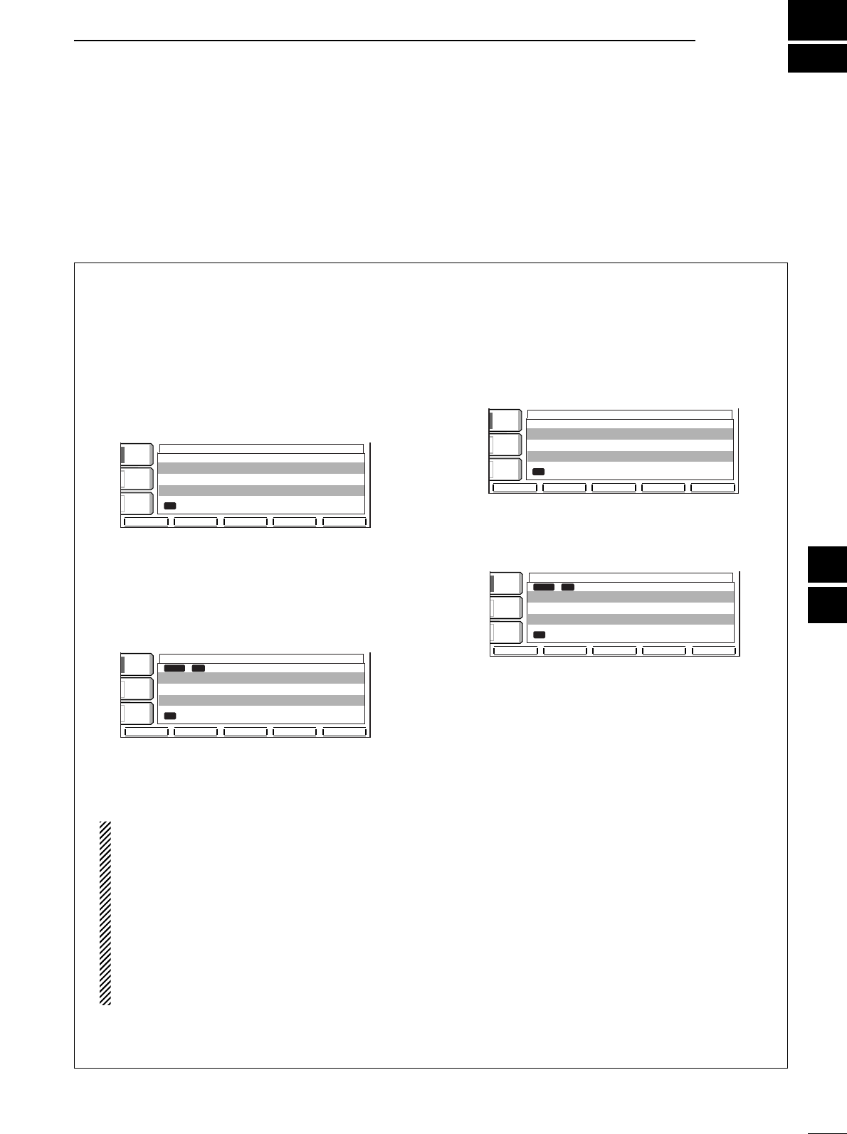
7
72
VOICE RECORDER FUNCTIONS
■Digital voice recorder
The transceiver has a total of 8 memory channels, 4
each for transmit and receive, of digital voice memo-
ries. A maximum message length of 15 sec. can be
recorded in each receive channel, and a total message
length of 90 sec. can be recorded in transmit channels.
Providing a transmission memory is very convenient
for repeated CQ and number transmissions at contest
times, as well as when making consecutive calls in
DX’pedition.
•Recording a received audio
qPush [EXIT/SET] several times to close a multi-
function screen, if necessary.
wSelect the desired mode by pushing [SSB],
[CW/RTTY] or [AM/FM].
ePush [(F-2)VOICE] to call up the voice recorder
screen.
•If the transmit voice memory channel (T1–T4) appears,
push [(F-5)T/R] to select receive voice memory chan-
nel.
rPush the desired memory channel switch,
[(F-1)R1] – [(F-4)R4], for 1 sec. to start recording.
•“REC” flashes and the recording timer counts up.
•The operating frequency, mode and current time are
programmed as the memory names automatically.
•Previously recorded contents are cleared.
tPush the selected memory channel switch,
[(F-1)R1] – [(F-4)R4], again to stop recording.
•Recording is automatically terminated after 30 min.
IMPORTANT!
Push one of [(F-1)R1]–[(F-4)R4] to stop record-
ing before, or when 15 sec. has passed from the
start of recording.
The voice recorder memory records the 15 sec.
(max.) of audio before one of [(F-1)R1]–[(F-
4)R4] is pushed.
For example, when recording 20 sec. of audio,
the first 5 sec. audio will be over-recorded with
the last 5 sec., so that the total of audio
recorded is 15 sec. only.
yPush [EXIT/SET] twice to exit the voice memory
screen.
•Playing the recorded audio
qPush [EXIT/SET] several times to close a multi-
function screen, if necessary.
wPush [(F-2)VOICE] to call up the voice recorder
screen.
•If the transmit voice memory channel (T1–T4) appears,
push [(F-5)T/R] to select receive voice memory chan-
nel.
ePush the desired memory channel switch,
[(F-1)R1] – [(F-4)R4], momentarily to playback.
•“PLAY” appears.
rPush the selected memory channel switch,
[(F-1)R1] – [(F-4)R4], again to stop playback if de-
sired.
•Playback is terminated automatically when all of the
recorded contents in the channel are played, or after
15 sec.
tPush [EXIT/SET] twice to exit the voice memory
screen.
VOICE RECORDERVOICE RECORDER
COMPCOMP
OFFOFF
WIDEWIDE
AGCAGC
MIDMID
VOXVOX
OFFOFF
R1 R2R2 R3R3 R4R4 T/RT/R
PLAYPLAY
R1R1 14.195.0014.195.00 USBUSB 10:1010:10 5s5s
R2R2 ------
R3R3 ------
R4R4 ------
RXRX MEMORYMEMORY
R1R1 R2R2 R3R3 R4R4 T/RT/R
VOICE RECORDERVOICE RECORDER
COMPCOMP
OFFOFF
WIDEWIDE
AGCAGC
MIDMID
VOXVOX
OFFOFF
R1R1 14.100.0014.100.00 USBUSB 15:3015:30 8s8s
R2R2 ------
R3R3 ------
R4R4 ------
RXRX MEMORYMEMORY
VOICE RECORDER
VOICE RECORDER
COMP
COMP
OFF
OFF
WIDE
WIDE
AGC
AGC
MID
MID
VOX
VOX
OFF
OFF
R1
R1
R2
R2
R3
R3
R4
R4
T/R
T/R
REC
REC
R1
R1
14.195.00
14.195.00
USB
USB
10:10
10:10
10s
10s
R2
R2
---
---
R3
R3
---
---
R4
R4
---
---
RX
RX
MEMORY
MEMORY
R1
R1
R2
R2
R3
R3
R4
R4
T/R
T/R
VOICE RECORDER
VOICE RECORDER
COMP
COMP
OFF
OFF
WIDE
WIDE
AGC
AGC
MID
MID
VOX
VOX
OFF
OFF
R1
R1
14.100.00
14.100.00
USB
USB
15:30
15:30
8s
8s
R2
R2
---
---
R3
R3
---
---
R4
R4
---
---
RX
RX
MEMORY
MEMORY
7
6
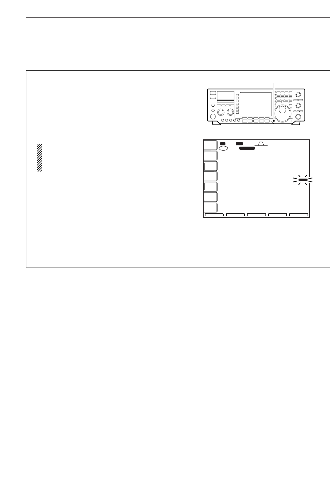
73
7VOICE RECORDER FUNCTIONS
•One-touch voice recording
To record the receiving signal contents immediately,
one-touch voice recording is available.
qPush [REC/PLAY] for 1 sec. while receiving a sig-
nal to start recording.
•“REC” flashes.
•Records audio into the channel R4.
wPush [REC/PLAY] momentarily to stop recording.
•Recording is automatically terminated after 30 min.
IMPORTANT!
Push [REC/PLAY] to stop recording before, or
when 15 sec. has passed from the start of
recording.
•One-touch playback
The recorded audio in the channel R4 can be play-
back without selecting the voice memory screen.
qPush [REC/PLAY] to playback.
•“PLAY” appears.
•Playback the recorded audio in the channel R4.
wPush [REC/PLAY] again to stop playback if de-
sired.
•Playback is terminated automatically when all of the
recorded contents in the channel R4 are played, or
after 15 sec.
BWBW 2.4k2.4k SFTSFT 0
FIL2FIL2
USBUSB
RECREC
qw:pp
TXTX
VFOVFO USBUSB
USBUSB
USBUSB
FIL2FIL2
qr.qot.pp
qr.wpt.pp
14.100.0014.100.00
14.100.0014.100.00
1
1
VFOVFO
ANTANT
1
COMPCOMP
OFFOFF
WIDEWIDE
METERMETER
PoPo
P.AMPP.AMP
1
AGCAGC
MIDMID
ATTATT
OFFOFF
VOXVOX
OFFOFF
SCOPESCOPE VOICEVOICE MEMORYMEMORY SCANSCAN
[REC/PLAY] switch
■Digital voice recorder (continued)
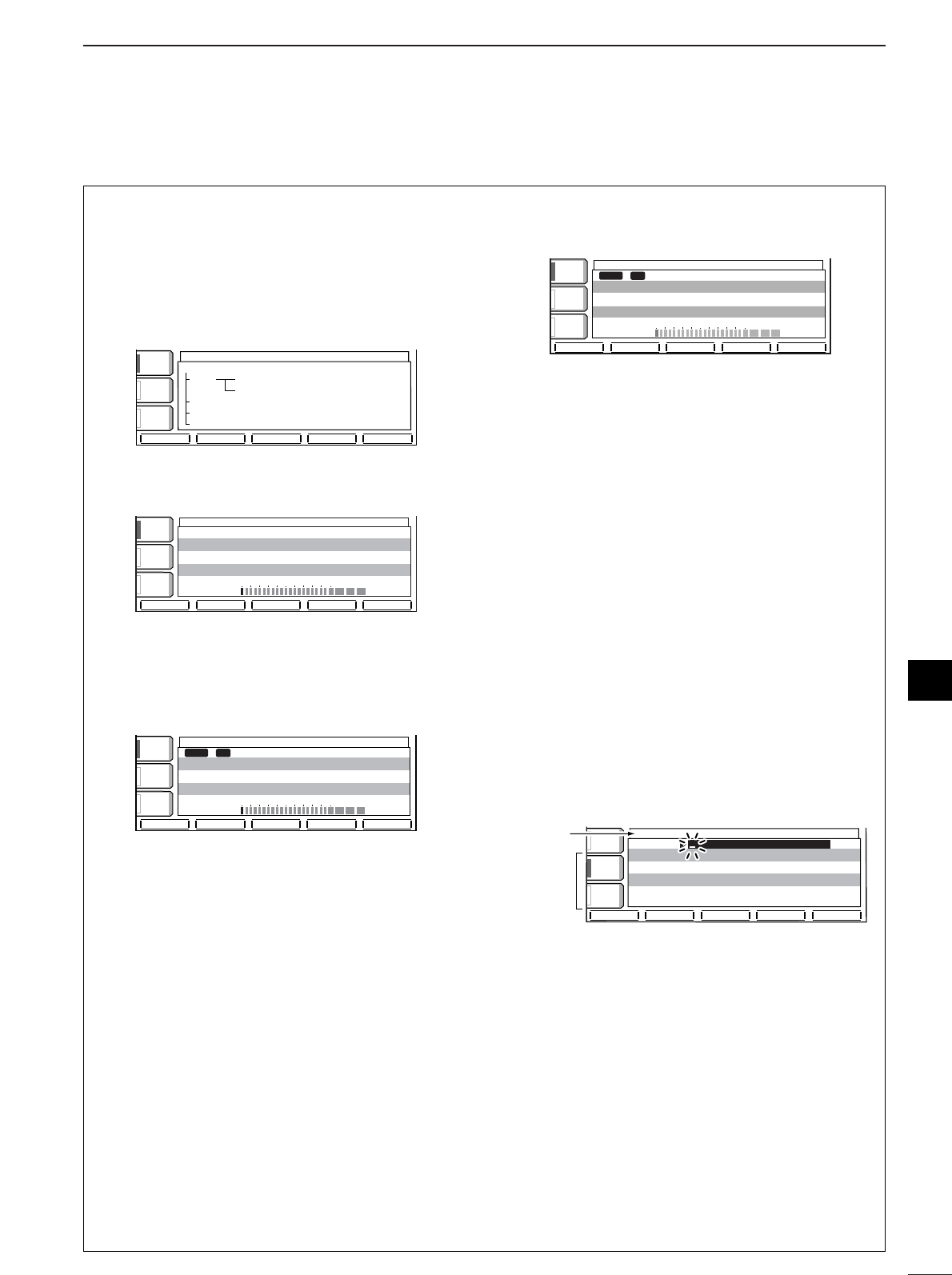
74
7
VOICE RECORDER FUNCTIONS
■Digital voice recorder (continued)
•Recording a message for transmit
To transmit a message using a voice recorder, record
the desired message in advance as described below.
qPush [EXIT/SET] several times to close a multi-
function screen, if necessary.
wPush [(F-2)VOICE] to call up the voice recorder
screen.
ePush [(F-2)MIC REC] to select the voice memory
recording screen.
rPush the desired memory channel switch,
[(F-1)T1] – [(F-4)T4], for 1 sec. to start recording.
•Speak into the microphone without pushing the [PTT]
switch.
•Previously recorded contents are cleared.
tAdjust the [MIC GAIN] control so that the [REC
LEVEL] indicator reads within 100%.
yPush the selected memory channel switch,
[(F-1)T1] – [(F-4)T4], again to stop recording.
•Recording is automatically terminated when the total
time of recorded messages, T1–T4, becomes 90 sec.
uPush [EXIT/SET] twice to exit the voice memory
screen.
•Confirming a message for transmit
qPush [EXIT/SET] several times to close a multi-
function screen, if necessary.
wPush [(F-2)VOICE] to call up the voice recorder
screen.
ePush [(F-2)MIC REC] to select the voice memory
recording screen.
rPush the desired memory channel switch,
[(F-1)T1] – [(F-4)T4], momentarily to start playback
and confirmation.
tPush the selected memory channel switch,
[(F-1)T1] – [(F-4)T4], again to stop playback if de-
sired.
yPush [EXIT/SET] twice to exit the voice memory
screen.
•Programming a memory name for
transmit
Memory channels can be tagged with alphanumeric
names of up to 20 characters each.
Capital letters, small letters, numerals, some symbols
(! # $ % & ¥ ? " ' ` ^ + – ✱/ .,: ; = < > ( ) [ ] { } | _ _)
and spaces can be used. (See step tbelow.)
qRecord a message as described at left.
wCall up the voice memory recording screen as de-
scribed in steps qto eat left.
ePush [(F-5)NAME] to enter memory name edit
condition.
•Acursor appears and blinks.
rPush [(F-5)T1..T4] several times to select the de-
sired voice memory.
tInput the desired character by rotating the tuning
dial or by pushing the band key for number input.
•Push [ABC] or [abc] to toggle capital and small letters.
•Push [123] or [etc] to toggle numerals and symbols.
•Push [(F-1)Ω] or [(F-2)≈] for cursor movement.
•Push [(F-3)DEL] to delete the selected character.
•Push [(F-4)SPACE] to input a space.
•Pushing the transceiver’s keypad, [0]–[9], can also
enter numerals.
yPush [EXIT/SET] to input and set the name.
•The cursor disappears.
uRepeat steps rto yto program another voice
memory’s name, if desired.
iPush [EXIT/SET] twice to exit the voice memory
screen.
ABCABC
123123
T4T4 -
-
-
T1T1 10s10s
T3T3 -
-
-
VOICE MIC-RECORDVOICE MIC-RECORD
T2T2 -
-
-
ABCABC
çåDELDEL SPACESPACE T1..T4T1..T4
Character
group
keys
Selected
character
VOICE MIC-RECORDVOICE MIC-RECORD
COMPCOMP
OFFOFF
WIDEWIDE
AGCAGC
MIDMID
VOXVOX
OFFOFF
RECREC LEVELLEVEL
05050 100100 % % RemainRemain
80s 80s
T1T1 T2T2 T3T3 T4T4 NAMENAME
PLAYPLAY
T1T1 10s10s
T2T2 ------
T3T3 ------
T4T4 ------
COMPCOMP
OFFOFF
WIDEWIDE
AGCAGC
MIDMID
VOXVOX
OFFOFF
RECREC LEVELLEVEL
05050 100100 % % RemainRemain
80s 80s
VOICE MIC-RECORDVOICE MIC-RECORD
T1T1 T2T2 T3T3 T4T4 NAMENAME
RECREC
T1T1 10s10s
T2T2 ------
T3T3 ------
T4T4 ------
VOICE MIC-RECORDVOICE MIC-RECORD
COMPCOMP
OFFOFF
WIDEWIDE
AGCAGC
MIDMID
VOXVOX
OFFOFF
RECREC LEVELLEVEL
05050 100100 % % RemainRemain
90s 90s
T1T1 T2T2 T3T3 T4 NAMENAME
T1T1 ------
T2T2 ------
T3T3 ------
T4T4 ------
VOICE RECORDERVOICE RECORDER
COMPCOMP
OFFOFF
WIDEWIDE
AGCAGC
MIDMID
VOXVOX
OFFOFF
PLAYPLAY MIC RECMIC REC TX LEV.TX LEV. SETSET
VOICE RECORDER MENUVOICE RECORDER MENU
PLAY PLAY TX Variable TX Variable ◊ 4ch (Total 90s) 4ch (Total 90s)
RX 15s Endless RX 15s Endless ◊ 4ch (TOT 30m) 4ch (TOT 30m)
MIC REC Mic Record/Record check MIC REC Mic Record/Record check
TX LEV. Recorder Output Adjust TX LEV. Recorder Output Adjust
SET Auto Monitor SET SET Auto Monitor SET
7
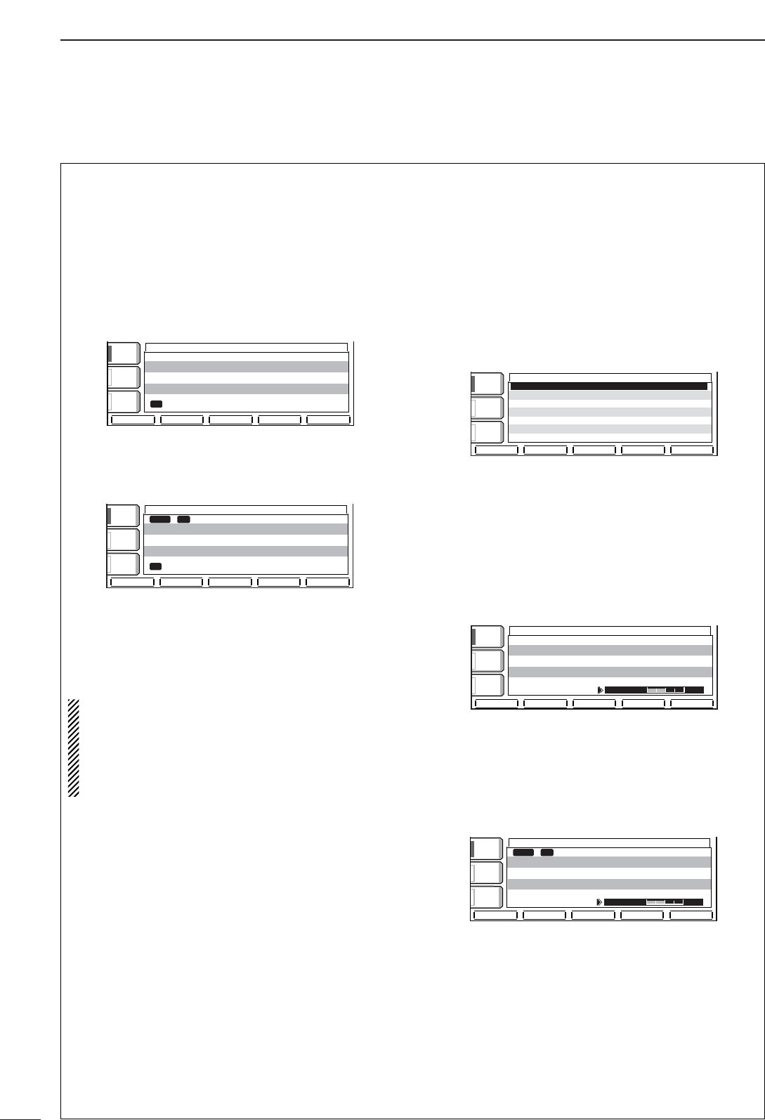
75
7VOICE RECORDER FUNCTIONS
■Digital voice recorder (continued)
•Sending a message for transmit
qPush [EXIT/SET] several times to close a multi-
function screen, if necessary.
wSelect a phone mode by pushing [SSB] or
[AM/FM].
ePush [(F-2)VOICE] to call up the voice recorder
screen.
•If the receive voice memory channel (R1–R4) appears,
push [(F-5)T/R] to select transmit voice memory chan-
nel.
rPush the desired memory channel switch,
[(F-1)T1] – [(F-4)T4], momentarily to transmit the
contents.
tPush the selected memory channel switch,
[(F-1)T1] – [(F-4)T4], again to stop, if desired.
yPush [EXIT/SET] twice to exit the voice memory
screen.
For your information
When an external keypad is connected to the pin 3
and pin 7 of the [MIC] connecter, the recorded
message, T1–T4, can be transmitted without open-
ing the voice recorder set screen.
See page 73 for details.
•Transmit monitor function
The monitor function can be automatically turned ON
while transmitting a voice memory message.
qCall up the voice recorder screen as described at
left.
wPush [EXIT/SET] then [(F-5)SET] to select the
voice recorder set screen.
eRotate the tuning dial to turn the monitor function
ON and OFF.
•Push [(F-3)DEF] for 1 sec. to select the default condi-
tion.
rPush [EXIT/SET] to return to the voice recorder
screen.
•Transmit level setting
qCall up the voice recorder screen as described at
left.
wPush [(F-3)TX LEV.] to select the voice memory
transmit level set mode screen.
ePush the desired memory channel switch,
[(F-1)T1] – [(F-4)T4], momentarily to transmit the
contents.
rRotate the tuning dial to adjust the transmit voice
level.
•Push [(F-5)DEF] to select the default condition.
tPush [EXIT/SET] to return to the voice recorder
screen.
VOICE RECORDERVOICE RECORDER
TXTX_LEVELLEVEL 50%50%
COMPCOMP
OFFOFF
WIDEWIDE
AGCAGC
MIDMID
VOXVOX
OFFOFF
T1T1 T2T2 T3T3 T4T4 DEFDEF
SENDSEND
T1T1 CQCQJA3YUAJA3YUA 10s10s
T2T2 ------
T3T3 ------
T4T4 ------
VOICE RECORDERVOICE RECORDER
TXTX LEVELLEVEL 50%50%
COMPCOMP
OFFOFF
WIDEWIDE
AGCAGC
MIDMID
VOXVOX
OFFOFF
T1T1 T2T2 T3T3 T4T4 DEFDEF
T1T1 CQCQJA3YUAJA3YUA 10s10s
T2T2 ------
T3T3 ------
T4T4 ------
VOICE SET
COMPCOMP
OFFOFF
WIDEWIDE
AGCAGC
MIDMID
VOXVOX
OFFOFF
DEFDEF
AutoAutoMonitorMonitor ONON
VOICE RECORDER
VOICE RECORDER
COMP
COMP
OFF
OFF
WIDE
WIDE
AGC
AGC
MID
MID
VOX
VOX
OFF
OFF
T1
T1
T2
T2
T3
T3
T4
T4
T/R
T/R
SEND
SEND
TX
TX
MEMORY
MEMORY
T1
T1
CQ JA3YUA
CQ JA3YUA
10s
10s
T2
T2
---
---
T3
T3
---
---
T4
T4
---
---
VOICE RECORDER
VOICE RECORDER
COMP
COMP
OFF
OFF
WIDE
WIDE
AGC
AGC
MID
MID
VOX
VOX
OFF
OFF
T1
T1
T2
T2
T3
T3
T4
T4
T/R
T/R
T1
T1
CQ JA3YUA
CQ JA3YUA
10s
10s
T2
T2
---
---
T3
T3
---
---
T4
T4
---
---
TX
TX
MEMORY
MEMORY
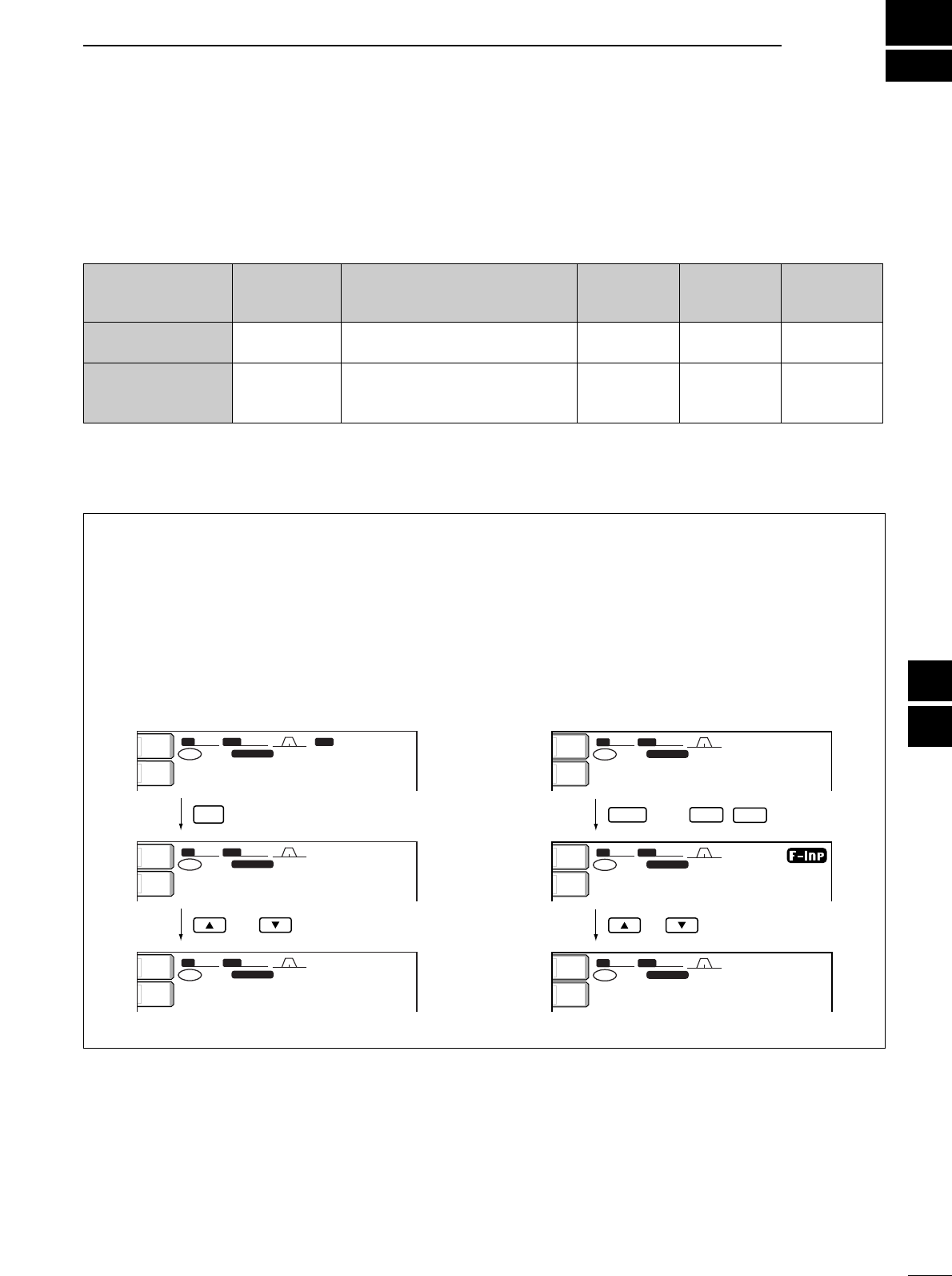
8
76
MEMORY OPERATION
7
8
■Memory channels
The transceiver has 101 memory channels. The mem-
ory mode is very useful for quickly changing to often-
used frequencies.
All 101 memory channels are tuneable which means
the programmed frequency can be tuned temporarily
with the tuning dial, etc. in memory mode.
■Memory channel selection
•Using the [YY] or [ZZ] keys
qPush [VFO/MEMO] to select memory mode.
wPush [Y]/[Z] several times to select the desired
memory channel.
•Push and hold [Y]/[Z] for continuous selection.
•[UP] and [DN] on the microphone can also be used.
eTo return to VFO mode, push [VFO/MEMO] again.
•Using the keypad
qPush [VFO/MEMO] to select memory mode.
wPush [F-INP].
ePush the desired memory channel number using
the keypad.
•Enter 100 or 101 to select scan edge channel P1 or P2,
respectively.
rPush [Y] or [Z] to select the desired memory
channel.
SFTSFT 0
FIL2FIL2
CWCW
qw:pp
TXTX
USBUSB
qr.qot.pp
14.100.0014.100.00
BPFBPF
1
VFOVFO
BWBW 500 500
SFTSFT 0
FIL2FIL2
USBUSB
qw:pp
TXTX
CWCW
qr.qpp.pp
14.195.0014.195.00
VFOVFO
1
BWBW 2.4k2.4k
SFTSFT 0
FIL2FIL2
USBUSB
qw:pp
TXTX
wr.oyp.pp
1212
BWBW 2.4k2.4k
CWCW
14.195.0014.195.00
VFOVFO
ANTANT
1
METERMETER
PoPo
ANTANT
1
METERMETER
PoPo
ANTANT
1
METERMETER
PoPo
VFO/
MEMO
or
F-INPENT
SFTSFT 0
FIL2FIL2
USBUSB
qw:pp
TXTX
CWCW
qr.qpp.pp
14.195.0014.195.00
VFOVFO
1
BWBW 2.4k2.4k
SFTSFT 0
FIL2FIL2
USBUSB
TXTX
CWCW
.qpp.qw
14.195.0014.195.00
VFOVFO
1
BWBW 2.4k2.4k
SFTSFT 0
FIL2FIL2
USBUSB
qw:pp
TXTX
wr.oyp.pp
1212
BWBW 2.4k2.4k
CWCW
14.195.0014.195.00
VFOVFO
ANTANT
1
METERMETER
PoPo
ANTANT
1
METERMETER
PoPo
ANTANT
1
METERMETER
PoPo
12
or
then
MEMORY MEMORY TRANSFER OVER-
CHANNEL CHANNEL CAPABILITY TO VFO WRITING CLEAR
NUMBER
Regular memory 1–99 One frequency and one mode Yes Yes Yes
channels in each memory channel.
Scan edge
One frequency and one mode in
memory P1, P2 each memory channel as scan Yes Yes No
channels edges for programmed scan.
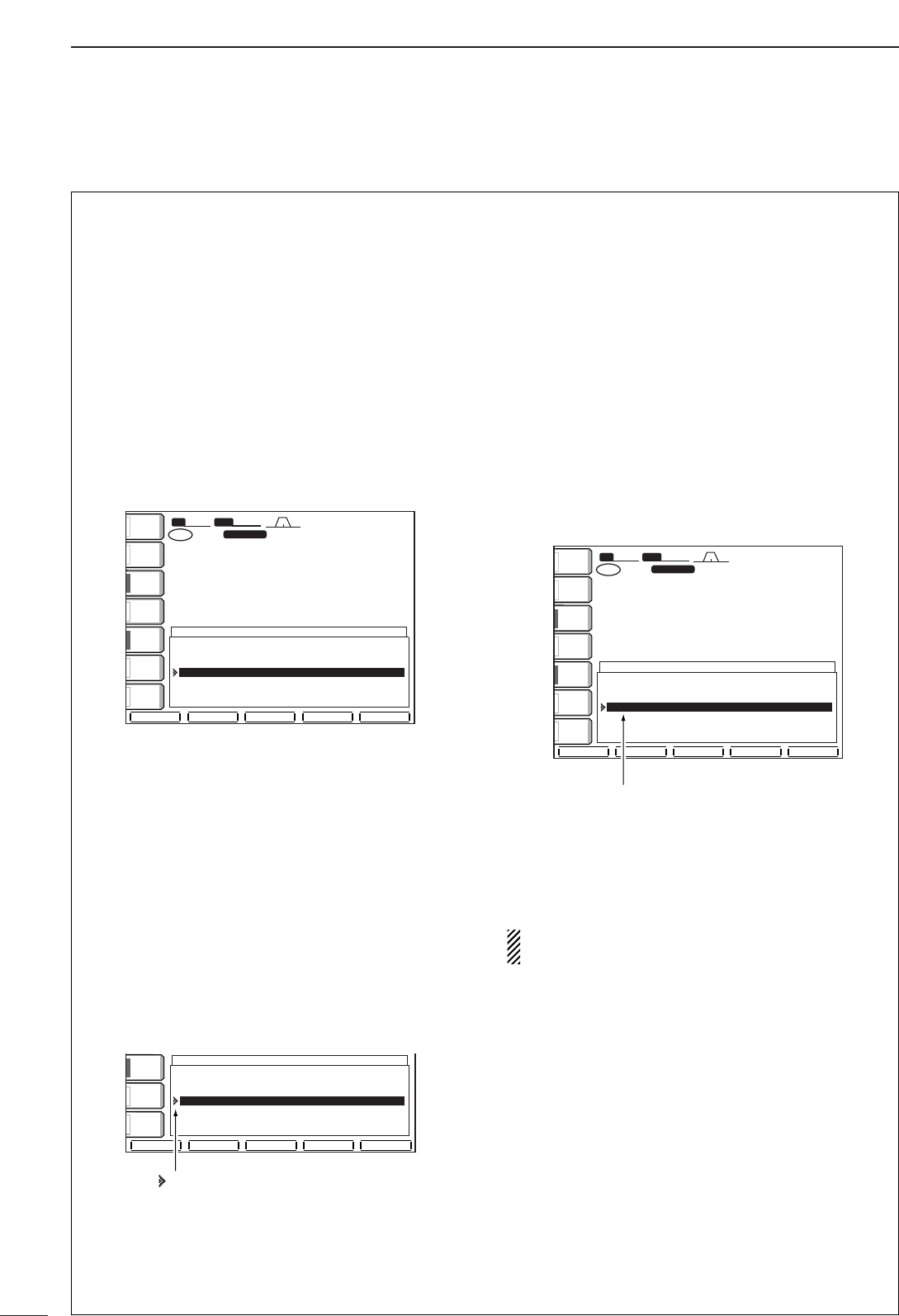
77
8MEMORY OPERATION
■Memory channel screen
The memory channel screen simultaneously shows 7
memory channels and their programmed contents. 13
memory channels can be displayed in the wide mem-
ory channel screen.
You can select a desired memory channel from the
memory channel screen.
•Selecting a memory channel using the
memory channel screen
qPush [EXIT/SET] several times to close a multi-
function screen, if necessary.
wPush [(F-4)MEMORY] to select the memory chan-
nel screen.
•[(F-5)WIDE] switches the standard and wide screens.
eRotate the tuning dial while pushing [(F-2)SET] to
select the desired memory channel.
•[Y] and [Z] can also be used.
rPush [EXIT/SET] to exit the memory channel
screen.
•Confirming programmed memory
channels
qSelect the memory channel screen as described
above.
wRotate the tuning dial while pushing [(F-1)ROLL]
to scroll the screen.
ePush [(F-2)SET] to select the highlighted memory
channel, if desired.
rPush [EXIT/SET] to exit the memory channel
screen.
•Setting a memory channel as a select
memory
Select memory channels are used for select memory
scan. Select memory scan repeatedly scans the se-
lect memory channels only. This is useful to speed up
the memory scan interval. Of course, select memory
channels are also scanned during normal memory
scan.
qSelect the memory channel screen as described at
left.
wRotate the tuning dial while pushing [(F-1)ROLL]
or [(F-2)SET] to select the desired memory chan-
nel.
•[Y] and [Z] can also be used.
ePush [(F-3)SELECT] to set the memory channel
as a select memory or not.
rRepeat steps wto eto program another memory
channel as a select memory channel, if desired.
tPush [EXIT/SET] to exit the memory channel
screen.
Setting select memory channels is also possible in
the scan screen.
ROLL
ROLL
SET
SET
SELECT
SELECT
NAME
NAME
WIDE
WIDE
SFT
SFT
0
FIL2
FIL2
USB
USB
qw:pp
TX
TX
VFO
VFO
USB
USB
USB
USB
USB
USB
FIL2
FIL2
qr.qot.pp
qr.wpt.pp
14.100.00
14.100.00
14.100.00
14.100.00
1
1ß
ß
VFO
VFO
BW
BW
2.4k
2.4k
99
99
--.---.--
--.---.--
------
------
---
---
P1
P1
0.500.00
0.500.00
LSB
LSB
FL2
FL2
SCAN EDGE
SCAN EDGE
P2
P2
29.999.99
29.999.99
USB
USB
FL2
FL2
SCAN EDGE
SCAN EDGE
1ß 14.100.00
14.100.00
USB
USB
FL2
FL2
2 --.---.--
--.---.--
------
------
---
---
3 --.---.--
--.---.--
------
------
---
---
4 --.---.--
--.---.--
------
------
---
---
MEMORY
MEMORY
ANT
ANT
1
COMP
COMP
OFF
OFF
WIDE
WIDE
METER
METER
Po
P.AMP
P.AMP
1
AGC
AGC
MID
MID
ATT
ATT
OFF
OFF
VOX
VOX
OFF
OFF
“ß” appears for select memory channel.
ROLL
ROLL
SET
SET
SELECT
SELECT
NAME
NAME
WIDE
WIDE
99
99
--.---.--
--.---.--
------
------
---
---
P1
P1
0.500.00
0.500.00
LSB
LSB
FL2
FL2
SCAN EDGE
SCAN EDGE
P2
P2
29.999.99
29.999.99
USB
USB
FL2
FL2
SCAN EDGE
SCAN EDGE
1ß 14.100.00
14.100.00
USB
USB
FL2
FL2
2 --.---.--
--.---.--
------
------
---
---
3 --.---.--
--.---.--
------
------
---
---
4 --.---.--
--.---.--
------
------
---
---
MEMORY
MEMORY
COMP
COMP
OFF
OFF
WIDE
WIDE
AGC
AGC
MID
MID
VOX
VOX
OFF
OFF
“ ” appears when the memory
channel is selected.
ROLL
ROLL
SET
SET
SELECT
SELECT
NAME
NAME
WIDE
WIDE
SFT
SFT
0
FIL2
FIL2
USB
USB
qw:pp
TX
TX
VFO
VFO
USB
USB
USB
USB
USB
USB
FIL2
FIL2
qr.qot.pp
qr.wpt.pp
14.100.00
14.100.00
14.100.00
14.100.00
1
1
VFO
VFO
BW
BW
2.4k
2.4k
99
99
--.---.--
--.---.--
------
------
---
---
P1
P1
0.500.00
0.500.00
LSB
LSB
FL2
FL2
SCAN EDGE
SCAN EDGE
P2
P2
29.999.99
29.999.99
USB
USB
FL2
FL2
SCAN EDGE
SCAN EDGE
1 14.100.00
14.100.00
USB
USB
FL2
FL2
2 --.---.--
--.---.--
------
------
---
---
3 --.---.--
--.---.--
------
------
---
---
4 --.---.--
--.---.--
------
------
---
---
MEMORY
MEMORY
ANT
ANT
1
COMP
COMP
OFF
OFF
WIDE
WIDE
METER
METER
Po
P.AMP
P.AMP
1
AGC
AGC
MID
MID
ATT
ATT
OFF
OFF
VOX
VOX
OFF
OFF
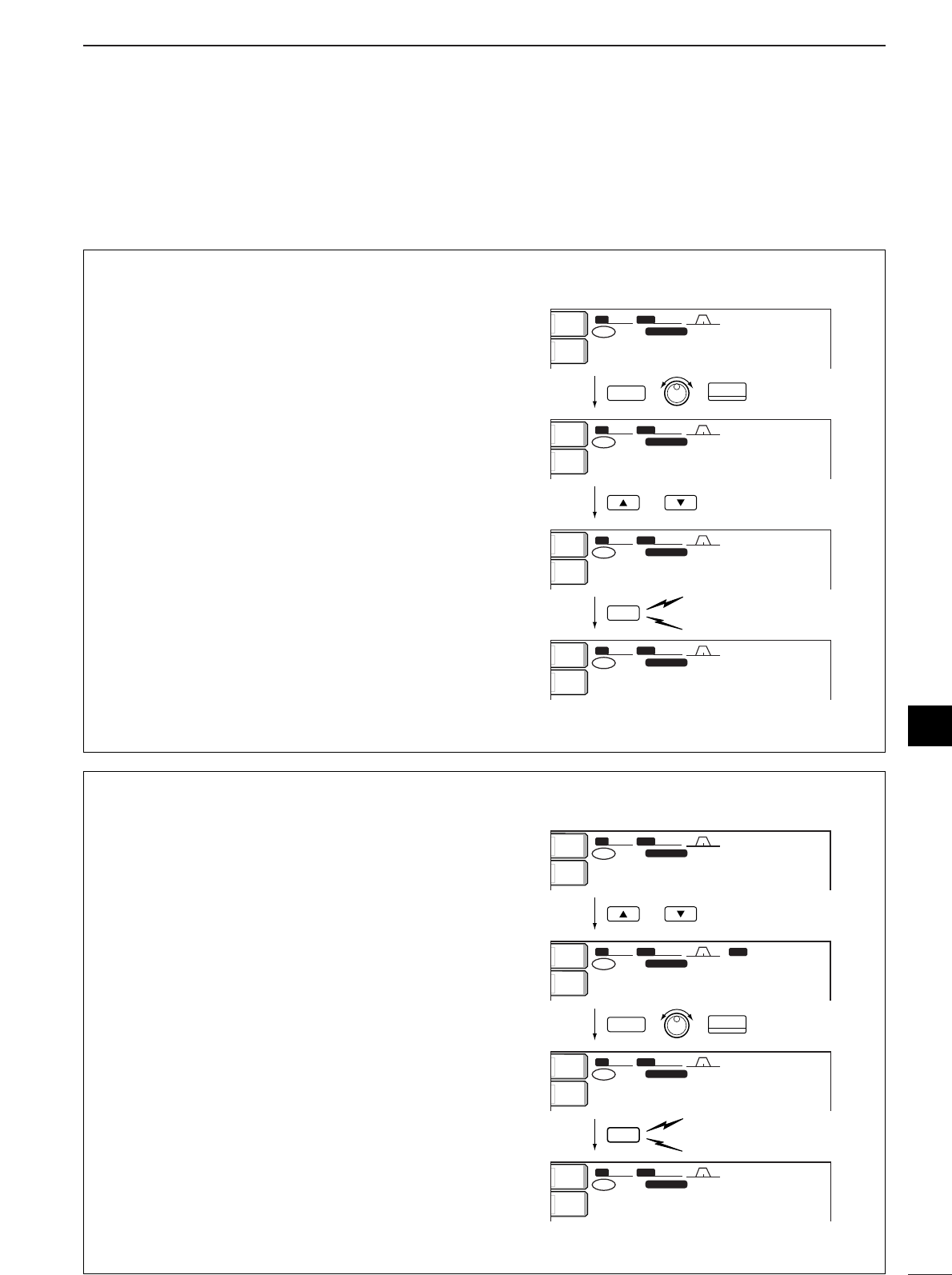
78
8
MEMORY OPERATION
8
■Memory channel programming
Memory channel programming can be preformed ei-
ther in VFO mode or in memory mode.
•Programming in VFO mode
qSet the desired frequency and operating mode in
VFO mode.
wPush [Y]/[Z] several times to select the desired
memory channel.
•Memory channel screen is convenient for selecting the
desired channel.
•Memory channel contents appear in the memory chan-
nel readout (below the frequency readout).
•“--.---.--” appears if the selected memory channel is a
blank channel (and does not have contents).
ePush [MW] for 1 sec. to program the displayed fre-
quency and operating mode into the memory
channel.
[EXAMPLE]: Programming 7.088 MHz/LSB into
memory channel 12.
7
3
SSB
MW
or
Push for 1 sec.
Beep
Beep
Beep
SFTSFT 0
FIL2FIL2
USBUSB
qw:pp
TXTX
USBUSB
qr.qpp.pp
14.195.0014.195.00
1
VFOVFO
BWBW 2.4k2.4k
SFTSFT 0
FIL2FIL2
LSBLSB
qw:pp
TXTX
USBUSB
u.pii.pp
14.195.0014.195.00
1
VFOVFO
BWBW 2.4k2.4k
SFTSFT 0
FIL2FIL2
LSBLSB
qw:pp
TXTX u.pii.pp
--.---.----.---.--
1212
VFOVFO
BWBW 2.4k2.4k
SFTSFT 0
FIL2FIL2
LSBLSB
qw:pp
TXTX
LSBLSB
u.pii.pp
7.088.007.088.00
1212
VFOVFO
BWBW 2.4k2.4k
ANTANT
1
METERMETER
PoPo
ANTANT
1
METERMETER
PoPo
ANTANT
1
METERMETER
PoPo
ANTANT
1
METERMETER
PoPo
•Programming in memory mode
qSelect the desired memory channel with [Y]/[Z] in
memory mode.
•Memory channel contents appear in the memory chan-
nel readout (below the frequency readout).
•“--.---.--” appears if the selected memory channel is a
blank channel (and does not have contents).
wSet the desired frequency and operating mode in
memory mode.
•To program a blank channel, use direct frequency entry
with the keypad or memo pads, etc.
ePush [MW] for 1 sec. to program the displayed fre-
quency and operating mode into the memory
channel.
[EXAMPLE]: Programming 21.280 MHz/USB into
memory channel 18.
SFTSFT 0
FIL2FIL2
LSBLSB
qw:pp
TXTX
USBUSB
u.pii.pp
14.195.0014.195.00
VFOVFO
1212
BWBW 2.4k2.4k
SFTSFT 0
FIL2FIL2
CWCW
qw:pp
TXTX
USBUSB
e.tpw.pp
14.195.0014.195.00
VFOVFO
1818
BWBW 500500 BPFBPF
SFTSFT 0
FIL2FIL2
USBUSB
qw:pp
TXTX
USBUSB
wq.wip.pp
14.195.0014.195.00
VFOVFO
1818
BWBW 2.4k2.4k
SFTSFT 0
FIL2FIL2
USBUSB
qw:pp
TXTX
USBUSB
wq.wip.pp
14.195.0014.195.00
1818
BWBW 2.4k2.4k
ANTANT
1
METERMETER
PoPo
ANTANT
1
METERMETER
PoPo
ANTANT
1
METERMETER
PoPo
ANTANT
1
METERMETER
PoPo
21
7
MW
or
Push for 1 sec.
Beep
Beep
Beep
SSB
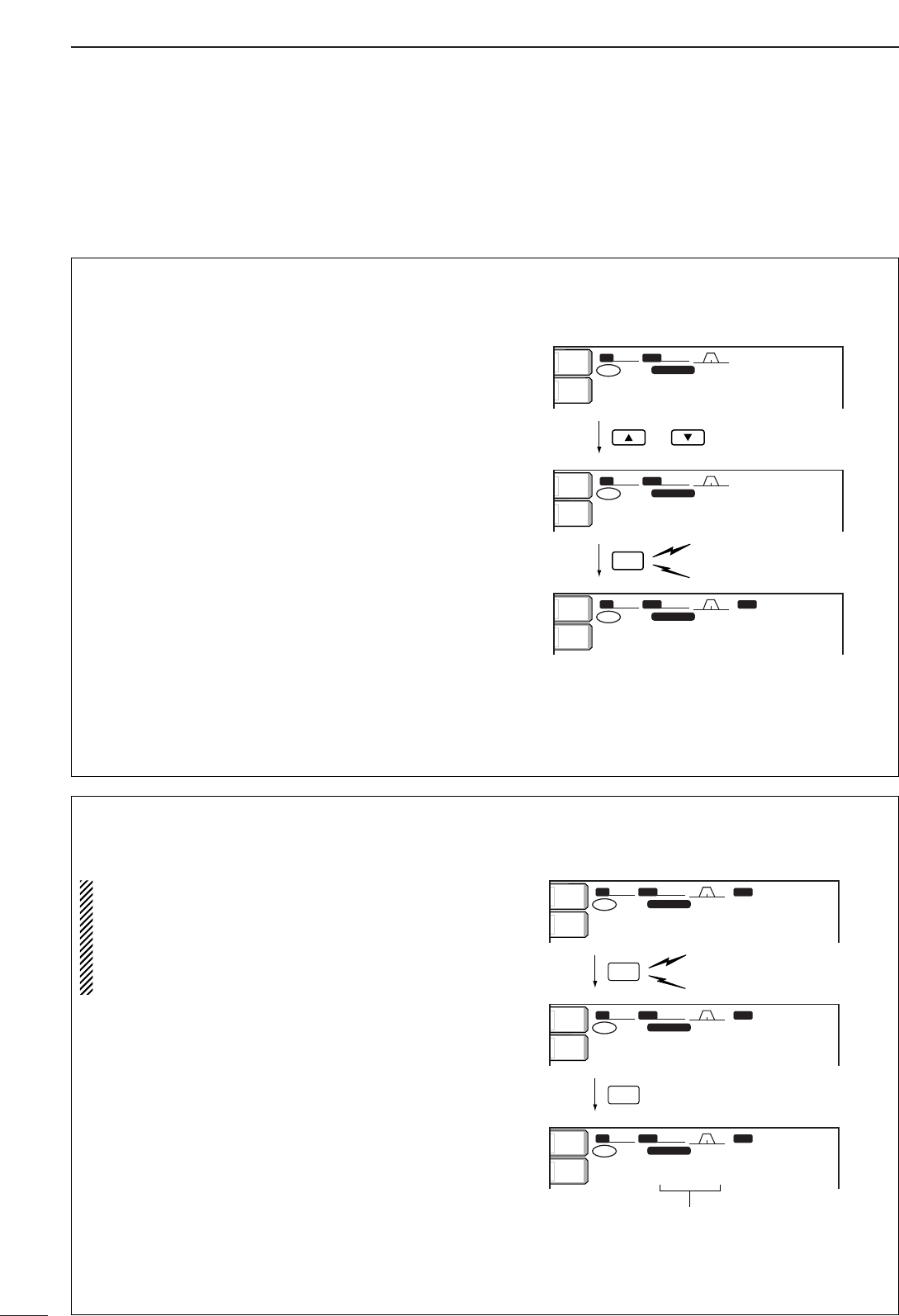
79
8MEMORY OPERATION
■Frequency transferring
The frequency and operating mode in a memory chan-
nel can be transferred to the VFO.
Frequency transferring can be performed in either VFO
mode or memory mode.
•Transferring in VFO mode
This is useful for transferring programmed contents to
VFO.
qSelect VFO mode with [VFO/MEMO].
wSelect the memory channel to be transferred with
[Y]/[Z].
•Memory channel screen is convenient for selecting the
desired channel.
•Memory channel contents appear in the memory chan-
nel readout (below the frequency readout).
•“--.---.--” appears if the selected memory channel is a
blank channel. In this case transferring is impossible.
ePush [VFO/MEMO] for 1 sec. to transfer the fre-
quency and operating mode.
•Transferred frequency and operating mode appear on
the frequency readout.
TRANSFERRING EXAMPLE IN VFO MODE
Operating frequency : 21.320 MHz/USB (VFO)
Contents of M-ch 16 : 14.018 MHz/CW
or
Push for 1 sec.
Beep
Beep
Beep
SFTSFT 0
FIL2FIL2
USBUSB
qw:pp
TXTX
USBUSB
wq.ewp.pp
14.950.0014.950.00
1
VFOVFO
BWBW 2.4k2.4k
SFTSFT 0
FIL2FIL2
USBUSB
qw:pp
TXTX
CWCW
wq.ewp.pp
14.018.0014.018.00
1616
VFOVFO
BWBW 2.4k2.4k
SFTSFT 0
FIL2FIL2
CWCW
qw:pp
TXTX
CWCW
qr.pqi.pp
14.018.0014.018.00
1616
VFOVFO
BWBW 500500 BPFBPF
ANTANT
1
METERMETER
PoPo
ANT
1
METERMETER
Po
ANT
1
METERMETER
Po
VFO/
MEMO
•Transferring in memory mode
This is useful for transferring frequency and operat-
ing mode while operating in memory mode.
When you have changed the frequency or operat-
ing mode in the selected memory channel:
•Displayed frequency and mode are transferred.
•Programmed frequency and mode in the mem-
ory channel are not transferred, and they remain
in the memory channel.
qSelect the memory channel to be transferred with
[Y]/[Z] in memory mode.
•And, set the frequency or operating mode if required.
wPush [VFO/MEMO] for 1 sec. to transfer the fre-
quency and operating mode.
•Displayed frequency and operating mode are trans-
ferred to the VFO.
eTo return to VFO mode, push [VFO/MEMO] mo-
mentarily.
TRANSFERRING EXAMPLE IN MEMORY MODE
Operating frequency : 14.020 MHz/CW (M-ch 16)
Contents of M-ch 16 : 14.018 MHz/CW
Push for 1 sec.
Programmed contents appear.
Beep
Beep
Beep
VFO/
MEMO
VFO/
MEMO
SFTSFT 0
FIL2FIL2
CWCW
qw:pp
TXTX
USBUSB
qr.pwp.pp
21.320.0021.320.00
VFOVFO
1616
BWBW 500500
SFTSFT 0
FIL2FIL2
CWCW
qw:pp
TXTX
CWCW
qr.pwp.pp
14.018.0014.018.00
1616
VFOVFO
BWBW 500500
SFTSFT 0
FIL2FIL2
CWCW
qw:pp
TXTX
CWCW
qr.pwp.pp
14.020.0014.020.00
VFOVFO
1616
BWBW 500500
BPFBPF
BPFBPF
BPFBPF
ANTANT
1
METERMETER
PoPo
ANTANT
1
METERMETER
PoPo
ANTANT
1
METERMETER
PoPo
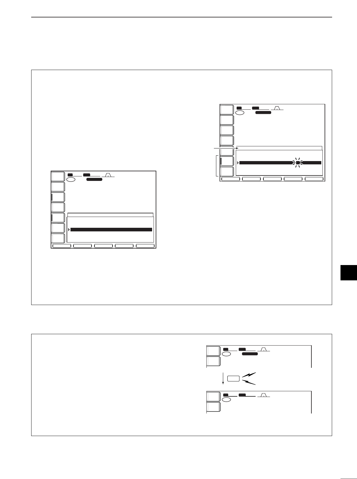
80
8
MEMORY OPERATION
8
■Memory names
All memory channels (including scan edges) can be
tagged with alphanumeric names of up to 10 charac-
ters each.
Capital letters, small letters, numerals, some symbols
(! # $ % & ¥ ? " ’ ` ^ + – ✱/ .,: ; = < > ( ) [ ] { } | _ _)
and spaces can be used.
•Editing (programming) memory names
qPush [EXIT/SET] several times to close a multi-
function screen, if necessary.
wPush [(F-4)MEMORY] to select the memory chan-
nel screen.
eSelect the desired memory channel.
rPush [(F-4)NAME] to edit memory channel name.
•Acursor appears and blinks.
•Memory channel names of blank channels cannot be
edited.
tInput the desired character by rotating the tuning
dial or by pushing the band key for number input.
•Push [ABC] or [abc] to toggle capital and small letters.
•Push [123] or [etc] to toggle numerals and symbols.
•Push [(F-1)Ω] or [(F-2)≈] for cursor movement.
•Push [(F-3)DEL] to delete the selected character.
•Push [(F-4)SPACE] to input a space.
•Pushing the transceiver’s keypad, [0]–[9], can also
enter numerals.
yPush [EXIT/SET] to input and set the name.
•The cursor disappears.
uRepeat steps eto yto program another memory
channel’s name, if desired.
iPush [EXIT/SET] to exit the memory channel
screen.
123123
ABCABC
SFTSFT 0
FIL2FIL2
USBUSB
qw:pp
TXTX
VFOVFO USBUSB
USBUSB
USBUSB
FIL2FIL2
qr.qot.pp
qr.wpt.pp
14.100.0014.100.00
14.100.0014.100.00
1
1
VFOVFO
BWBW 2.4k2.4k
9999 --.---.----.---.-- ------------ ------
P1P1 0.500.000.500.00 LSBLSB FL2FL2 SCAN EDGESCAN EDGE
P2P2 29.999.9929.999.99 USBUSB FL2FL2 SCAN EDGESCAN EDGE
1 14.100.0014.100.00 USBUSB FL2FL2 _
2 --.---.----.---.-- ------------ ------
3 --.---.----.---.-- ------------ ------
4 --.---.----.---.-- ------------ ------
MEMORYMEMORY
çåDELDEL SPACESPACE WIDEWIDE
ABCABC
Character
group
keys
Selected
character
ROLLROLL SETSET SELECTSELECT NAMENAME WIDEWIDE
SFTSFT 0
FIL2FIL2
USBUSB
qw:pp
TXTX
VFOVFO USBUSB
USBUSB
USBUSB
FIL2FIL2
qr.qot.pp
qr.wpt.pp
14.100.0014.100.00
14.100.0014.100.00
1
1
VFOVFO
BWBW 2.4k2.4k
9999 --.---.----.---.-- ------------ ------
P1P1 0.500.000.500.00 LSBLSB FL2FL2 SCAN EDGESCAN EDGE
P2P2 29.999.9929.999.99 USBUSB FL2FL2 SCAN EDGESCAN EDGE
1 14.100.0014.100.00 USBUSB FL2FL2
2 --.---.----.---.-- ------------ ------
3 --.---.----.---.-- ------------ ------
4 --.---.----.---.-- ------------ ------
MEMORYMEMORY
ANTANT
1
COMPCOMP
OFFOFF
WIDEWIDE
METERMETER
PoPo
P.AMPP.AMP
1
AGCAGC
MIDMID
ATTATT
OFFOFF
VOXVOX
OFFOFF
■Memory clearing
Any unnecessary memory channels can be cleared.
The cleared memory channels become blank chan-
nels.
qSelect memory mode with [VFO/MEMO].
wSelect the desired memory channel with [Y]/[Z].
ePush [M-CL] for 1 sec. to clear the contents.
•The programmed frequency and operating mode dis-
appear.
rTo clear other memory channels, repeat steps w
and e.
SFTSFT 0
FIL2FIL2
USBUSB
qw:pp
TXTX
wr.oyp.pp
1212
BWBW 2.4k2.4k
SFTSFT 0
qw:pp
TXTX
CWCW
≥qot≥pp
14.195.0014.195.00
VFOVFO
1212
BWBW 2.4k2.4k
CWCW
14.195.0014.195.00
VFOVFO
ANTANT
1
METERMETER
PoPo
ANTANT
1
METERMETER
PoPo
Push for 1 sec.
M-CL Beep
Beep
Beep
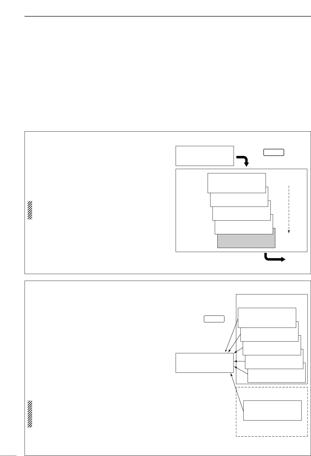
81
8MEMORY OPERATION
■Memo pads
The transceiver has a memo pad function to store fre-
quency and operating mode for easy write and recall.
The memo pads are separate from memory channels.
The default number of memo pads is 5, however, this
can be increased to 10 in set mode if desired. (p. 101)
Memo pads are convenient when you want to memo-
rize a frequency and operating mode temporarily, such
as when you find a DX station in a pile-up, or when a
desired station is busy for a long time and you want to
temporarily search for other stations.
Use the transceiver’s memo pads instead of relying on
hastily scribbled notes that are easily misplaced.
•Writing frequencies and operating
modes into memo pads
You can simply write the accessed readout frequency
and operating mode by pushing [MP-W].
When you write a 6th frequency and operating mode,
the oldest written frequency and operating mode are
automatically erased to make room for the new set-
tings.
Each memo pad must have its own unique combi-
nation of frequency and operating mode; memo
pads having identical settings cannot be written.
Displayed frequency and mode
Push
Newest
The oldest written frequency
and mode are erased.
Oldest
MP-W
wq.wii.ww
USB
wq.wuy.pp
USB
wq.pwr.tw
USB
wq.pqi.py
USB
qr.qiw.rp
USB
qr.qot.pp
USB
MEMO
PADS
•Calling up a frequency from a memo pad
You can simply call up the desired frequency and op-
erating mode of a memo pad by pushing [MP-R] sev-
eral times.
•Both VFO and memory modes can be used.
•The frequency and operating mode are called up, starting
from the most recently written.
When you call up a frequency and an operating mode
from memo pads with [MP-R], the previously dis-
played frequency and operating mode are automati-
cally stored in a temporary pad. The frequency and
operating mode in the temporary pad can be recalled
by pushing [MP-R] several times.
•You may think there are 6 memo pads because 6 different
frequencies (5 are in memo pads and 1 is in the tempo-
rary pad) are called up by [MP-R].
If you change the frequency or operating mode
called up from a memo pad with the tuning dial,
etc., the frequency and operating mode in the tem-
porary pad are erased.
VFO or MEMORY
mode display
MEMO PADS
TEMPORARY PAD
Push
Pushing [MP-R] calls up the
frequency and operating
mode in a memo pad and
the temporary pad sequen-
tially.
Frequency and mode before
pushing [MP-R].
MP-R
wq.rit.pp
USB
qr.qot.pp
USB
wq.wuy.pp
USB
wq.pwr.tw
USB
wq.pqi.py
USB
qr.qiw.rp
USB
qr.qot.pp
USB
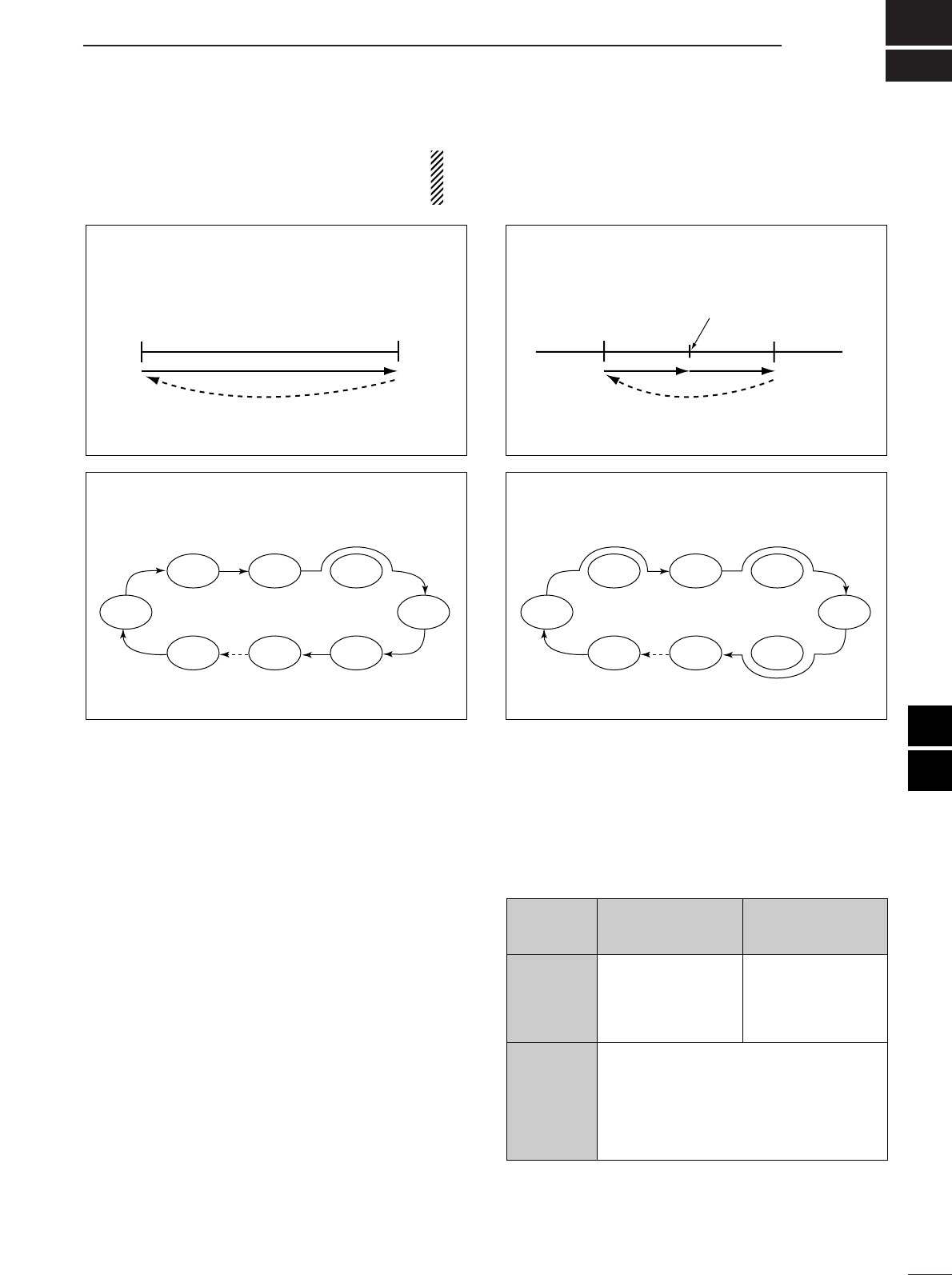
9
82
SCANS
■Scan types
■Preparation
•Channels
For programmed scan:
Program scan edge frequencies into scan edge mem-
ory channels P1 and P2.
For
∂
Fscan:
Set the ∂F span (∂F scan range) in the scan screen.
For memory scan:
Program 2 or more memory channels except scan
edge memory channels.
For select memory scan:
Designate 2 or more memory channels as select mem-
ory channels. To designate the channel as a select
memory channel, choose a memory channel, then
push [(F-3)SELECT] in the scan screen (memory
mode) or in the memory channel screen.
•Scan resume ON/OFF
You can select the scan to resume or cancel when de-
tecting a signal, in set mode. Scan resume ON/OFF
must be set before operating a scan. See p. 86 for
ON/OFF setting and scan resume condition details.
•Scan speed
Scan speed can be selected from 2 levels, high or low,
in set mode. See p. 86 for details.
•Squelch condition
•The scan function can be used on the main readout only.
•You can operate a scan while operating on a frequency using
the dualwatch or split functions. See p. 57 for details.
PROGRAMMED SCAN
Repeatedly scans between two scan edge frequencies
(scan edge memory channels P1 and P2).
This scan operates in VFO mode.
SELECT MEMORY SCAN
Repeatedly scans all select memory channels.
∂F SCAN
Repeatedly scans within ∂F span area.
This scan operates in memory mode.This scan operates in memory mode.
This scan operates in both VFO and memory modes.
Scan
Scan edge
P1 or P2 Scan edge
P2 or P1
Jump
Mch 1 Mch 5
Mch 2 Mch 3 Mch 4
Mch 6Mch 7Mch 99
MEMORY SCAN
Repeatedly scans all programmed memory channels.
Mch 1 Mch 5
Mch 2 Mch 3 Mch 4
Mch 6Mch 7Mch 99
ß (select)
ß (select)ß (select)
ß (select) ß (select)
Blank channel Blank channel
ß (select)
ß (select)ß (select)
ß (select) ß (select)
ScanScan
–∂F frequency +∂F frequency
Start frequency
Jump
SQUELCH
CLOSED
SQUELCH
OPEN
Scan stops when detecting a signal.
If you set scan resume ON in set mode, the
scan pauses for 10 sec. when detecting a
signal, then resumes. When a signal disap-
pears while scan is paused, scan resumes
2sec. later.
The scan continues
until it is stopped
manually, and does
not pause even if it
detects signals.
Scan pauses on
each channel when
the scan resume is
ON; not applicable
when OFF.
SCAN PROGRAMMED
STARTS SCAN MEMORY SCAN
WITH
8
9
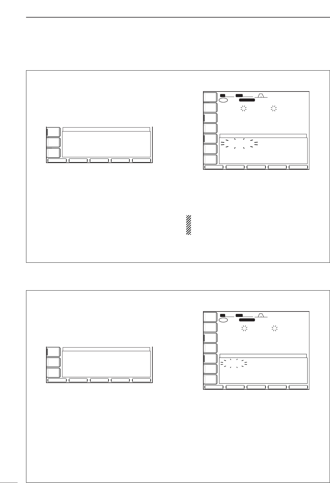
83
9SCANS
■Programmed scan operation
qPush [EXIT/SET] several times to close a multi-
function screen, if necessary.
wSelect VFO mode.
eSelect the desired operating mode.
•The operating mode can also be changed while scan-
ning.
rPush [(F-5)SCAN] to select the scan screen.
tSet [RF/SQL] open or closed.
•See previous page for scan condition.
•If the [RF/SQL] control function is set as “AUTO,” the
squelch is always open in SSB, CW and RTTY modes.
See pgs. 2, 30, 98 for details.
yPush [(F-1)PROG] to start the programmed scan.
•Decimal points blink while scanning.
uWhen the scan detects a signal, the scan stops,
pauses or ignores it depending on the resume set-
ting and the squelch condition.
iTo cancel the scan, push [(F-1)PROG].
If the same frequencies are programmed into the
scan edge memory channel P1 and P2, pro-
grammed scan does not start.
SFT
SFT
0
FIL2
FIL2
USB
USB
qw:pp
TX
TX
VFO
VFO
USB
USB
USB
USB
USB
USB
FIL2
FIL2
qr.qot.pp
qr.wpt.pp
14.100.00
14.100.00
14.100.00
14.100.00
1
1
VFO
VFO
BW
BW
2.4k
2.4k
SCAN
SCAN
ANT
ANT
1
COMP
COMP
OFF
OFF
WIDE
WIDE
METER
METER
Po
P.AMP
P.AMP
1
AGC
AGC
MID
MID
ATT
ATT
OFF
OFF
VOX
VOX
OFF
OFF
PROG
PROG
∂FFINE
FINE
∂F SPAN
F SPAN
SET
SET
PROGRAM SCAN
PROGRAM SCAN
∂FSpan
Span
:±
±
10kHz
10kHz
Programmed
Programmed
P1:
P1:
0.500.00MHz
0.500.00MHz
scan
scan
edges
edges
P2:
P2:
29.999.99MHz
29.999.99MHz
PROG
PROG
∂FFINE
FINE
∂F SPAN
F SPAN
SET
SET
SCAN
SCAN
COMP
COMP
OFF
OFF
WIDE
WIDE
AGC
AGC
MID
MID
VOX
VOX
OFF
OFF
∂FSpan
Span
:±
±
10kHz
10kHz
Programmed
Programmed
P1:
P1:
0.500.00MHz
0.500.00MHz
scan
scan
edges
edges
P2:
P2:
29.999.99MHz
29.999.99MHz
■∂∂F scan operation
qPush [EXIT/SET] several times to close a multi-
function screen, if necessary.
wSelect VFO mode or a memory channel.
eSelect the desired operating mode.
•The operating mode can also be changed while scan-
ning.
rPush [(F-5)SCAN] to select the scan screen.
tSet [RF/SQL] open or closed.
•See previous page for scan condition.
•If the [RF/SQL] control function is set as “AUTO,” the
squelch is always open in SSB, CW and RTTY modes.
See pgs. 3, 69 for details.
ySet the ∂F span by pushing [(F-4)∂F SPAN].
•±5 kHz, ±10 kHz, ±20 kHz, ±50 kHz, ±100 kHz,
±500 kHz and ±1000 kHz are selectable.
uSet center frequency of the ∂F span.
iPush [(F-2)∂F] to start the ∂F scan.
•Decimal points blink while scanning.
oWhen the scan detects a signal, the scan stops,
pauses or ignores it depending on the resume set-
ting and the squelch condition.
!0 To cancel the scan, push [(F-2)∂F].
SFTSFT 0
FIL2FIL2
USBUSB
qw:pp
TXTX
VFOVFO USBUSB
USBUSB
USBUSB
FIL2FIL2
qr.qot.pp
qr.wpt.pp
14.100.0014.100.00
14.100.0014.100.00
1
1
VFOVFO
BWBW 2.4k2.4k
SCANSCAN
ANTANT
1
COMPCOMP
OFFOFF
WIDEWIDE
METERMETER
Po
P.AMPP.AMP
1
AGCAGC
MIDMID
ATTATT
OFFOFF
VOXVOX
OFFOFF
PROGPROG ∂FFINEFINE ∂F SPANF SPAN SETSET
∂FSCANSCAN
∂FCenterCenter:14.195.00MHz14.195.00MHz
∂FSpanSpan:±±10kHz10kHz
ProgrammedProgrammedP1:P1:0.500.00MHz0.500.00MHz
scanscanedgesedgesP2:P2:29.999.99MHz29.999.99MHz
PROGPROG ∂FFINEFINE ∂F SPANF SPAN SETSET
SCANSCAN
COMPCOMP
OFFOFF
WIDEWIDE
AGCAGC
MIDMID
VOXVOX
OFFOFF
∂FSpanSpan:±±10kHz10kHz
ProgrammedProgrammedP1:P1:0.500.00MHz0.500.00MHz
scanscanedgesedgesP2:P2:29.999.99MHz29.999.99MHz
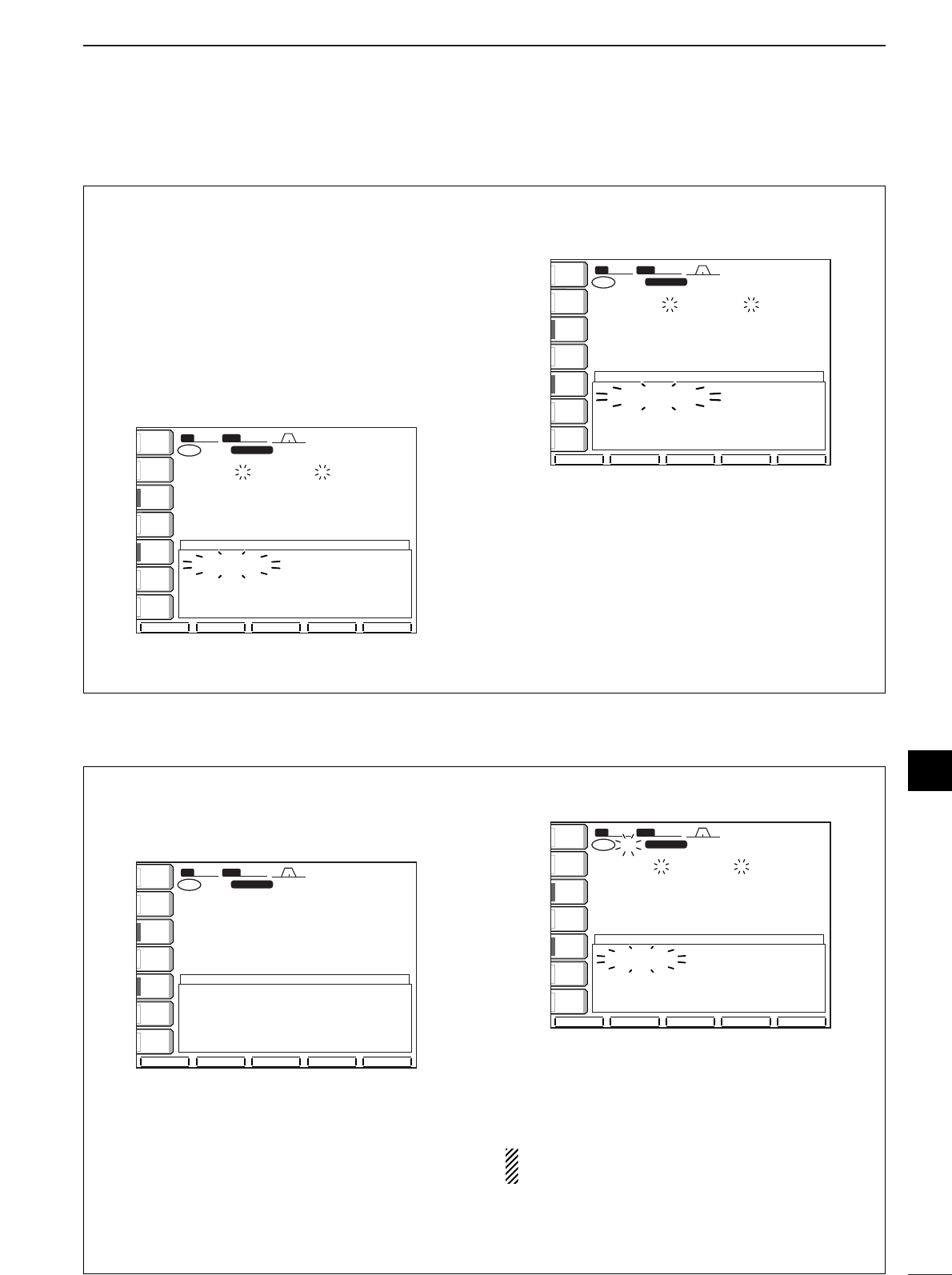
84
9
SCANS
■Fine programmed scan/fine ∂F scan
Fine scan functions as programmed or ∂F scan, but
scan speed decreases when the squelch opens but
does not stop. The scanning tuning step shifts from
50 Hz to 10 Hz while the squelch opens.
qPush [EXIT/SET] several times to close a multi-
function screen, if necessary.
wPush [(F-5)SCAN] to select the scan screen.
eSet for programmed scan or ∂F scan as described
on previous page.
rPush [(F-1)PROG] or [(F-2)∂F] to start a scan.
•Decimal points blink while scanning.
tPush [(F-3)FINE] to start a fine scan.
•“FINE PROGRAM SCAN” or “FINE ∂F SCAN” ap-
pears.
yWhen the scan detects a signal, the scan speed
decreases but does not stop.
uPush [(F-1)PROG] or [(F-2)∂F] to stop the scan;
push [(F-3)FINE] to cancel the fine scan.
SFTSFT 0
FIL2FIL2
USBUSB
qw:pp
TXTX
VFOVFO USBUSB
USBUSB
USBUSB
FIL2FIL2
qr.qot.pp
qr.wpt.pp
14.100.0014.100.00
14.100.0014.100.00
1
1
VFOVFO
BWBW 2.4k2.4k
SCANSCAN
ANTANT
1
COMPCOMP
OFFOFF
WIDEWIDE
METERMETER
PoPo
P.AMPP.AMP
1
AGCAGC
MIDMID
ATTATT
OFFOFF
VOXVOX
OFFOFF
PROGPROG ∂FFINEFINE ∂F SPANF SPAN SETSET
FINE PROGRAM SCANFINE PROGRAM SCAN
∂FSpanSpan:±±10kHz10kHz
ProgrammedProgrammedP1:P1:0.500.00MHz0.500.00MHz
scanscanedgesedgesP2:P2:29.999.99MHz29.999.99MHz
SFTSFT 0
FIL2FIL2
USBUSB
qw:pp
TXTX
VFOVFO USBUSB
USBUSB
USBUSB
FIL2FIL2
qr.qot.pp
qr.wpt.pp
14.100.0014.100.00
14.100.0014.100.00
1
1
VFOVFO
BWBW 2.4k2.4k
SCANSCAN
ANTANT
1
COMPCOMP
OFFOFF
WIDEWIDE
METERMETER
PoPo
P.AMPP.AMP
1
AGCAGC
MIDMID
ATTATT
OFFOFF
VOXVOX
OFFOFF
PROGPROG ∂FFINEFINE ∂F SPANF SPAN SETSET
PROGRAM SCANPROGRAM SCAN
∂FSpanSpan:±±10kHz10kHz
ProgrammedProgrammedP1:P1:0.500.00MHz0.500.00MHz
scanscanedgesedgesP2:P2:29.999.99MHz29.999.99MHz
■Memory scan operation
qPush [EXIT/SET] several times to close a multi-
function screen, if necessary.
wSelect memory mode.
ePush [(F-5)SCAN] to select the scan screen.
rSet [RF/SQL] open or closed.
•See p. 82 for scan condition.
•If the [RF/SQL] control function is set as “AUTO,” the
squelch is always open in SSB, CW and RTTY modes.
See pgs. 2, 30, 98 for details.
tPush [(F-1)MEMO] to start the memory scan.
•Decimal points blink while scanning.
yWhen the scan detects a signal, the scan stops,
pauses or ignores it depending on the resume set-
ting and the squelch condition.
uTo cancel the scan, push [(F-1)MEMO].
2 or more memory channels must be programmed
for memory scan to start.
SFT
SFT
0
FIL2
FIL2
USB
USB
qw:pp
TX
TX
VFO
VFO
USB
USB
USB
USB
USB
USB
FIL2
FIL2
qr.qot.pp
qr.wpt.pp
14.100.00
14.100.00
14.100.00
14.100.00
1
VFO
VFO
12
12
BW
BW
2.4k
2.4k
SCAN
SCAN
ANT
ANT
1
COMP
COMP
OFF
OFF
WIDE
WIDE
METER
METER
Po
Po
P.AMP
P.AMP
1
AGC
AGC
MID
MID
ATT
ATT
OFF
OFF
VOX
VOX
OFF
OFF
MEMO
MEMO
∂FSELECT
SELECT
∂F SPAN
F SPAN
SET
SET
MEMORY SCAN
MEMORY SCAN
∂FSpan
Span
:±
±
10kHz
10kHz
Programmed
Programmed
P1:
P1:
0.500.00MHz
0.500.00MHz
scan
scan
edges
edges
P2:
P2:
29.999.99MHz
29.999.99MHz
SFT
SFT
0
FIL2
FIL2
USB
USB
qw:pp
TX
TX
VFO
VFO
USB
USB
USB
USB
USB
USB
FIL2
FIL2
qr.qot.pp
qr.wpt.pp
14.100.00
14.100.00
14.100.00
14.100.00
1
VFO
VFO
12
12
BW
BW
2.4k
2.4k
SCAN
SCAN
ANT
ANT
1
COMP
COMP
OFF
OFF
WIDE
WIDE
METER
METER
Po
Po
P.AMP
P.AMP
1
AGC
AGC
MID
MID
ATT
ATT
OFF
OFF
VOX
VOX
OFF
OFF
MEMO
MEMO
∂FSELECT
SELECT
∂F SPAN
F SPAN
SET
SET
∂FSpan
Span
:±
±
10kHz
10kHz
Programmed
Programmed
P1:
P1:
0.500.00MHz
0.500.00MHz
scan
scan
edges
edges
P2:
P2:
29.999.99MHz
29.999.99MHz
9
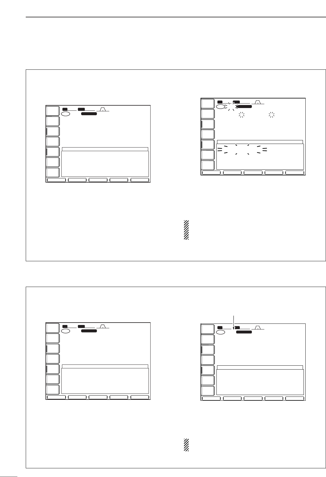
85
9SCANS
■Select memory scan operation
qPush [EXIT/SET] several times to close a multi-
function screen, if necessary.
wSelect memory mode.
ePush [(F-5)SCAN] to select the scan screen.
rSet [RF/SQL] open or closed.
•See p. 82 for scan condition.
•If the [RF/SQL] control function is set as “AUTO,” the
squelch is always open in SSB, CW and RTTY modes.
See pgs. 2, 30, 98 for details.
tPush [(F-1)MEMO] to start the memory scan.
•Decimal points blink while scanning.
yPush [(F-3)SELECT] to start select memory scan;
push [(F-3)SELECT] again to return to memory
scan, if desired.
uWhen the scan detects a signal, the scan stops,
pauses or ignores it depending on the resume set-
ting and the squelch condition.
iTo cancel the scan, push [(F-1)MEMO].
2 or more memory channels must be designated
as select memory channels for select memory
scan to start.
SFT
SFT
0
FIL2
FIL2
USB
USB
qw:pp
TX
TX
VFO
VFO
USB
USB
USB
USB
USB
USB
FIL2
FIL2
qr.qot.pp
qr.wpt.pp
14.100.00
14.100.00
14.100.00
14.100.00
1
VFO
VFO
BW
BW
2.4k
2.4k
SCAN
SCAN
12
12
ß
ANT
ANT
1
COMP
COMP
OFF
OFF
WIDE
WIDE
METER
METER
Po
P.AMP
P.AMP
1
AGC
AGC
MID
MID
ATT
ATT
OFF
OFF
VOX
VOX
OFF
OFF
MEMO
MEMO
∂FSELECT
SELECT
∂F SPAN
F SPAN
SET
SET
SELECT MEMORY SCAN
SELECT MEMORY SCAN
∂FSpan
Span
:±
±
10kHz
10kHz
Programmed
Programmed
P1:
P1:
0.500.00MHz
0.500.00MHz
scan
scan
edges
edges
P2:
P2:
29.999.99MHz
29.999.99MHz
SFT
SFT
0
FIL2
FIL2
USB
USB
qw:pp
TX
TX
VFO
VFO
USB
USB
USB
USB
USB
USB
FIL2
FIL2
qr.qot.pp
qr.wpt.pp
14.100.00
14.100.00
14.100.00
14.100.00
1
VFO
VFO
12
12
BW
BW
2.4k
2.4k
SCAN
SCAN
ANT
ANT
1
COMP
COMP
OFF
OFF
WIDE
WIDE
METER
METER
Po
Po
P.AMP
P.AMP
1
AGC
AGC
MID
MID
ATT
ATT
OFF
OFF
VOX
VOX
OFF
OFF
MEMO
MEMO
∂FSELECT
SELECT
∂F SPAN
F SPAN
SET
SET
∂FSpan
Span
:±
±
10kHz
10kHz
Programmed
Programmed
P1:
P1:
0.500.00MHz
0.500.00MHz
scan
scan
edges
edges
P2:
P2:
29.999.99MHz
29.999.99MHz
■Setting select memory channels
qPush [EXIT/SET] several times to close a multi-
function screen, if necessary.
wSelect memory mode.
ePush [(F-5)SCAN] to select the scan screen.
rSelect the desired memory channel to set as a se-
lect memory channel.
tPush [(F-3)SELECT] to set the memory channel
as a select memory or not.
yRepeat steps rto tto program another memory
channel as a select memory channel, if desired.
uPush [EXIT/SET] to exit the scan screen.
Select memory channels can also be set in the
memory channel screen. (p. 77)
12
12
ß
SFT
SFT
0
FIL2
FIL2
USB
USB
qw:pp
TX
TX
VFO
VFO
USB
USB
USB
USB
USB
USB
FIL2
FIL2
qr.qot.pp
qr.wpt.pp
14.100.00
14.100.00
14.100.00
14.100.00
1
VFO
VFO
BW
BW
2.4k
2.4k
SCAN
SCAN
ANT
ANT
1
COMP
COMP
OFF
OFF
WIDE
WIDE
METER
METER
Po
P.AMP
P.AMP
1
AGC
AGC
MID
MID
ATT
ATT
OFF
OFF
VOX
VOX
OFF
OFF
MEMO
MEMO
∂FSELECT
SELECT
∂F SPAN
F SPAN
SET
SET
“ß” appears for select memory channels.
∂FSpan
Span
:±
±
10kHz
10kHz
Programmed
Programmed
P1:
P1:
0.500.00MHz
0.500.00MHz
scan
scan
edges
edges
P2:
P2:
29.999.99MHz
29.999.99MHz
SFT
SFT
0
FIL2
FIL2
USB
USB
qw:pp
TX
TX
VFO
VFO
USB
USB
USB
USB
USB
USB
FIL2
FIL2
qr.qot.pp
qr.wpt.pp
14.100.00
14.100.00
14.100.00
14.100.00
1
VFO
VFO
12
12
BW
BW
2.4k
2.4k
SCAN
SCAN
ANT
ANT
1
COMP
COMP
OFF
OFF
WIDE
WIDE
METER
METER
Po
Po
P.AMP
P.AMP
1
AGC
AGC
MID
MID
ATT
ATT
OFF
OFF
VOX
VOX
OFF
OFF
MEMO
MEMO
∂FSELECT
SELECT
∂F SPAN
F SPAN
SET
SET
∂FSpan
Span
:±
±
10kHz
10kHz
Programmed
Programmed
P1:
P1:
0.500.00MHz
0.500.00MHz
scan
scan
edges
edges
P2:
P2:
29.999.99MHz
29.999.99MHz
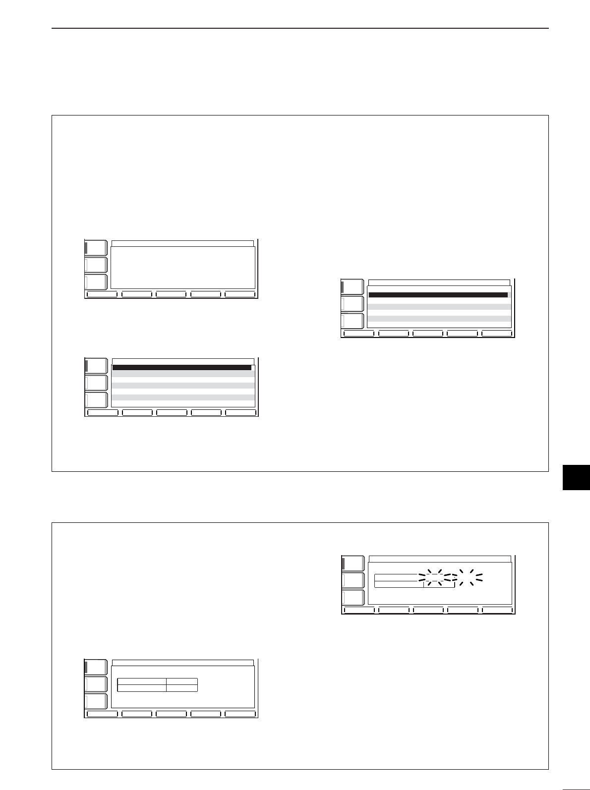
86
9
SCANS
■Scan set mode
Scan set mode is used for programming scanning
speed and scan resume condition.
•Scan speed
The transceiver has 2 speeds for scanning, high and
low.
qPush [EXIT/SET] several times to close a multi-
function screen, if necessary.
wPush [(F-5)SCAN] to select the scan screen.
ePush [(F-5)SET] to select the scan set mode
screen.
rPush [(F-1)Y] to select the scan speed item.
tRotate the tuning dial to select the scan speed.
•Push [(F-3)DEF] to select the default condition.
yPush [EXIT/SET] to exit the scan set mode.
•Scan resume condition
This item sets the scan resume function ON or OFF.
ON: scan resumes 10 sec. after stopping on a signal
(or 1 sec. after a signal disappears); OFF: scan does
not resume after stopping on a signal.
qPush [EXIT/SET] several times to close a multi-
function screen, if necessary.
wPush [(F-5)SCAN] to select the scan screen.
ePush [(F-5)SET] to select the scan set mode
screen.
rPush [(F-2)Z] to select the scan resume condition
item.
tRotate the tuning dial to turn the scan resume
function ON or OFF.
•Push [(F-3)DEF] to select the default condition.
yPush [EXIT/SET] to exit the scan set mode.
éèDEF
SCAN SET
COMPCOMP
OFFOFF
WIDEWIDE
AGCAGC
MIDMID
VOXVOX
OFFOFF
SCAN SpeedSCAN Speed HIGHHIGH
SCAN ResumeSCAN Resume ONON
éèDEF
SCAN SET
COMPCOMP
OFFOFF
WIDEWIDE
AGCAGC
MIDMID
VOXVOX
OFFOFF
SCAN SpeedSCAN Speed HIGHHIGH
SCAN ResumeSCAN Resume ONON
PROGPROG ∂FFINEFINE ∂F SPANF SPAN SETSET
SCANSCAN
COMPCOMP
OFFOFF
WIDEWIDE
AGCAGC
MIDMID
VOXVOX
OFFOFF
∂FSpanSpan:±±10kHz10kHz
ProgrammedProgrammedP1:P1:0.500.00MHz0.500.00MHz
scanscanedgesedgesP2:P2:29.999.99MHz29.999.99MHz
■Tone scan
The transceiver can detect the subaudible tone fre-
quency in a received signal. By monitoring a signal
that is being transmitted on a repeater input fre-
quency, you can determine the tone frequency re-
quired to access the repeater.
qSet the desired frequency or memory channel to
be checked for a tone frequency.
wPush [AM/FM] several times to select FM mode.
ePush [TONE] for 1 sec. to enter the tone frequency
screen.
rPush [(F-1)Y] or [(F-2)Z] to check the repeater
tone frequency or tone squelch frequency, respec-
tively. (pgs. 52, 53)
tPush [(F-5)T-SCAN] to start the tone scan.
•“SCAN” flashes while scanning.
yWhen the tone frequency is detected, the tone
scan pauses.
•The tone frequency is set temporarily on a memory
channel. Program into the memory channel to store the
tone frequency permanently.
•The decoded tone frequency is used for the repeater
tone frequency or tone squelch frequency.
uTo stop the scan, push [(F-5)T-SCAN].
iPush [EXIT/SET] to exit the tone frequency
screen.
TONE FREQUENCYTONE FREQUENCY
188.8Hz188.8Hz SCANSCAN
88.5Hz88.5HzT-SQL TONET-SQL TONE
REPEATER TONEREPEATER TONE
TONETONE
AGCAGC
FASTFAST
VOXVOX
OFFOFF
T-SCANT-SCAN
T-SCANT-SCAN
éèDEFDEF
TONE FREQUENCYTONE FREQUENCY
88.5Hz88.5Hz
88.5Hz88.5HzT-SQL TONET-SQL TONE
REPEATER TONEREPEATER TONE
AGCAGC
FASTFAST
VOXVOX
OFFOFF
TONETONE
OFFOFF
9
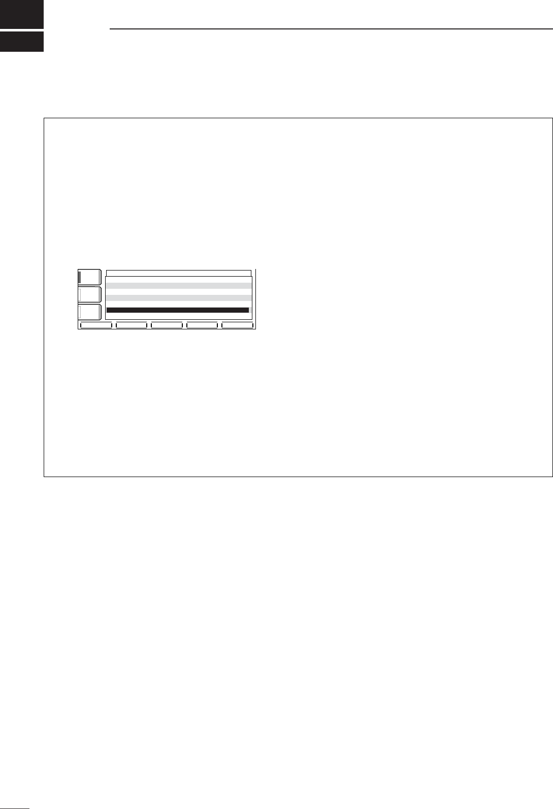
10
87
ANTENNA TUNER OPERATION
■Automatic antenna selection
The transceiver covers 0.1–60 MHz over 10 bands.
Each band key has a band memory which can mem-
orize a selected antenna (ANT1, ANT2, ANT1/RX an-
tenna and ANT2/RX antenna). When you change the
operating frequency beyond a band, the previously
used antenna is automatically selected for the new
band. This function is convenient when you use 2 or 3
antennas.
To use the band memory, enter set mode and confirm
that “Auto” is selected as the [ANT] switch item.
(p. 100)
•When OFF is selected, the [ANT] switch does not function
and [ANT1] is always selected.
•When “Manual” is selected, the [ANT] switch functions,
however, band memory does not function. In this case,
you must select an antenna manually.
•When “Auto” is selected (default setting), the antenna
tuner ON/OFF condition is also memorized in the band
memory.
•When “Auto” or “Manual” is selected, the antenna tuner
ON/OFF condition is consistent with the [ANT] switch.
•Antenna switch selection example
Under the following condition, “Auto” should be se-
lected as the [ANT] switch set mode item.
- When you use 2 antennas.
Under the following conditions, “Manual” should be
selected as the [ANT] switch set mode item.
- When using 1 antenna.
- When using an external antenna selector for more
than 3 antennas (except for receive antenna).
- When using an external antenna tuner.
DEFDEF WIDEWIDE
éè
VOXVOX
OFFOFF
COMPCOMP
OFFOFF
WIDEWIDE
AGCAGC
MIDMID
FMFMSPLITSPLITOffset(HF)Offset(HF) -0.100MHz-0.100MHz
FMFMSPLITSPLITOffset(50M)Offset(50M) -0.500MHz-0.500MHz
SPLITSPLITLOCKLOCK OFFOFF
TunerTuner(Auto(AutoStart)Start) OFFOFF
TunerTuner(PTT(PTTStart)Start) OFFOFF
[ANT][ANT]SwitchSwitch AutoAuto
RTTYRTTYMark FrequencyMark Frequency 21252125
OTHERSOTHERSSETSET
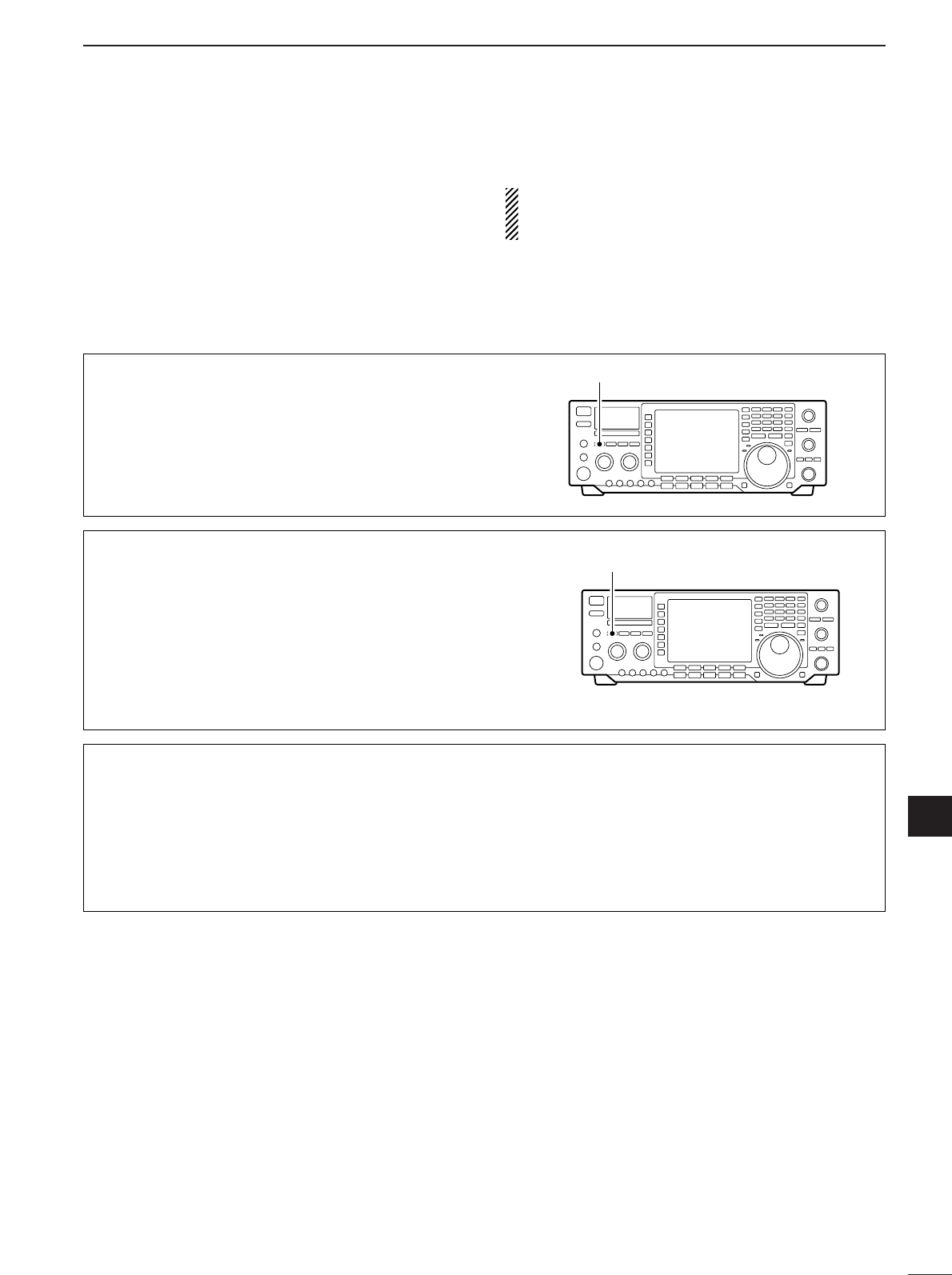
88
10
ANTENNA TUNER OPERATION
10
■Antenna tuner operation
The internal automatic antenna tuner matches the
transceiver to the connected antenna automatically.
Once the tuner matches an antenna, the variable ca-
pacitor angles are memorized as a preset point for
each frequency range (100 kHz steps). Therefore,
when you change the frequency range, the variable
capacitors are automatically preset to the memorized
point.
CAUTION: NEVER transmit with the tuner ON
when no antenna is connected. This will damage
the transceiver. Be careful of the antenna selection.
TUNER OPERATION
➥Push the [TUNER] switch to turn the internal an-
tenna tuner ON. The antenna is tuned automati-
cally when the antenna SWR is higher than 1.5:1.
•When the tuner is ON, the [TUNER] switch lights.
[TUNER] switch
MANUAL TUNING
During SSB operation at low voice levels, the internal
tuner may not be tuned correctly. In such cases, man-
ual tuning is helpful.
➥Push [TUNER] for 1 sec., to start manual tuning.
•Aside tone is emitted and [TUNER] blinks while tuning.
•If the tuner cannot reduce the SWR to less than 1.5:1
after 20 sec. of tuning, the [TUNER] switch indicator
goes out.
Push [TUNER] for 1 sec.
AUTOMATIC TUNER START (HF bands only)
If you want to deactivate the tuner under conditions
of VSWR 1.5:1 or less, use the auto tuner start func-
tion and turn the tuner OFF. This function activates
the tuner automatically when the SWR exceeds 1.5:1.
This function is turned ON in set mode. (p. 99).
PTT TUNER START
The tuner is always tuned when the PTT is pushed
after the frequency is changed (more than 1% from
last-tuned frequency). This function removes the
“push and hold [TUNER]” operation and activates for
the first transmission on a new frequency.
This function is turned ON in set mode. (p. 99).
NOTES:
•If the tuner cannot tune the antenna
Check the following and try again:
•the [ANT] connector selection.
•the antenna connection and feedline.
•the unaltered antenna SWR. (Less than 3:1 for HF bands;
Less than 2.5:1 for 50 MHz band)
•the transmit power. (8 W for HF bands; 15 W for 50 MHz
band)
•the power source voltage/capacity.
If the tuner cannot reduce the SWR to less than 1.5:1
after checking the above, perform the following:
•repeat manual tuning several times.
•tune with a 50 Ωdummy load and re-tune the antenna.
•turn power OFF and ON.
•adjust the antenna cable length.
(This is effective for higher frequencies in some cases.)
•Tuning a narrow bandwidth antenna
Some antennas, especially for low bands, have a nar-
row bandwidth. These antennas may not be tuned at
the edge of their bandwidth, therefore, tune such an
antenna as follows:
Suppose you have an antenna which has an SWR of
1.5:1 at 3.55 MHz and an SWR of 3:1 at 3.8 MHz.
qPush [TUNER] to turn the antenna tuner ON.
wSelect CW mode.
eTurn OFF the break-in function. (pgs. 4, 66)
rPush [TRANSMIT] to set to the transmit condition.
tSet 3.55 MHz and key down.
ySet 3.80 MHz and key down.
uPush [TRANSMIT] to return to the receive condition.
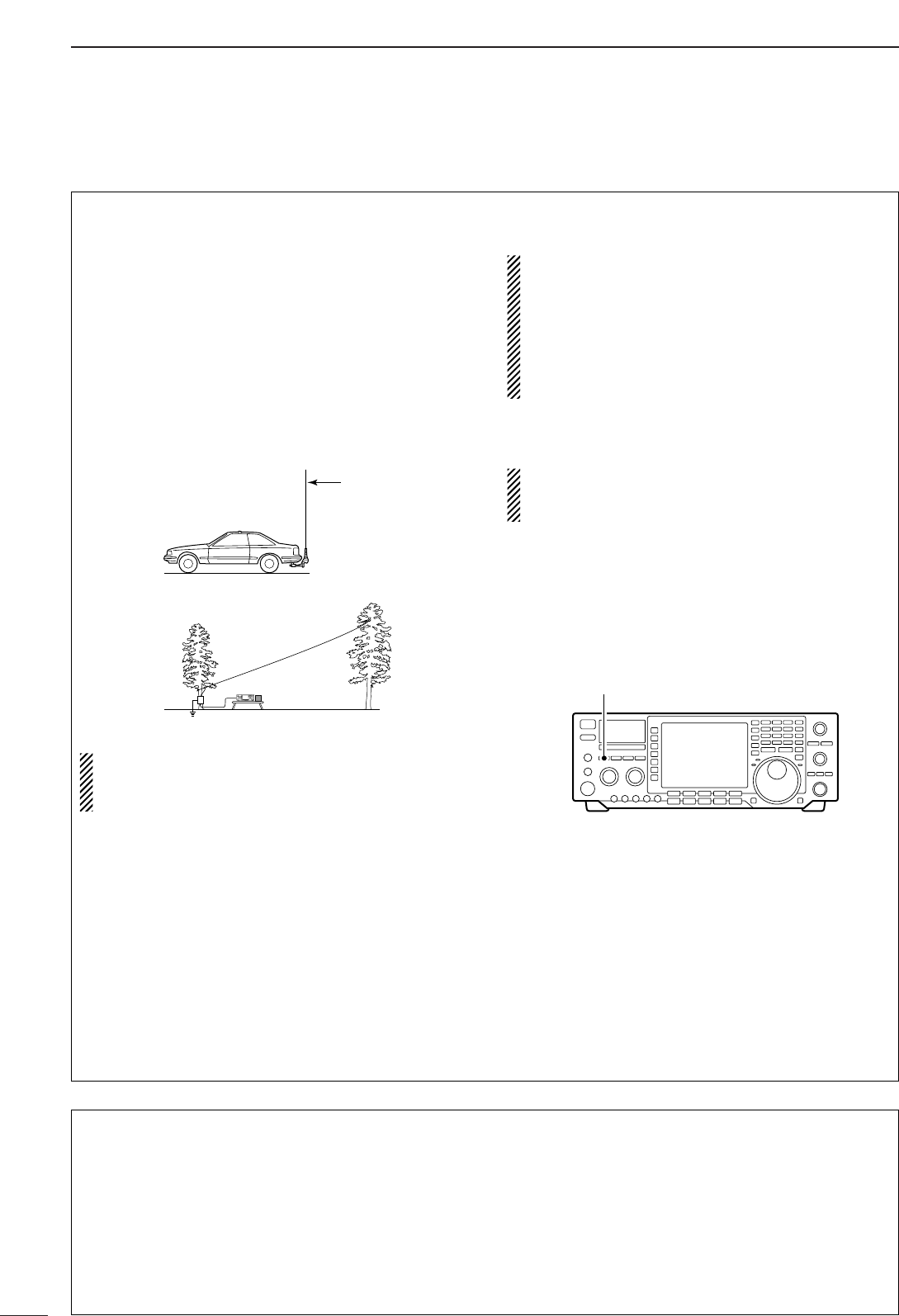
89
10 ANTENNA TUNER OPERATION
■Optional external tuner operation
•AH-4/AH-3 HF AUTOMATIC ANTENNA
TUNER
The AH-4 matches the IC-756PROIII to a long wire
antenna more than 7 m/23 ft long (3.5 MHz and above).
The AH-3 matches the IC-756PROIII to a long wire
antenna more than 3 m/10 ft long (3.5 MHz and above)
or more than 12 m/40 ft long (1.8 MHz and above).
•See p. 19 for the transceiver and AH-4/AH-3 connection.
•See the AH-4/AH-3 instruction manual for AH-4/AH-3 in-
stallation and antenna connection details.
AH-4/AH-3 setting example:
RWARNING: HIGH VOLTAGE!
NEVER touch the antenna element while tuning
or transmitting.
NEVER operate the AH-4/AH-3 without an antenna
wire. The tuner and transceiver will be damaged.
NEVER operate the AH-4/AH-3 when it is not
grounded.
Transmitting before tuning may damage the trans-
ceiver. Note that the AH-4/AH-3 cannot tune when
using a 1⁄2λlong wire or multiple of the operating fre-
quency.
•When connecting the AH-4/AH-3, the antenna
connector assignments are [ANT2] for the internal
tuner and [ANT1] for the AH-4/AH-3. The antenna
indicator in the LCD displays “ANT1(EXT)” when
the AH-4/AH-3 is connected and selected.
•The AH-3 can be used for HF bands only. It can-
not be used for the 50 MHz band.
•AH-4/AH-3 operation
Tuning is required for each frequency. Be sure to
re-tune the antenna before transmitting when you
change the frequency—even slightly.
qSet the desired frequency in an HF or 50 MHz
band for use with the AH-4. Set the desired fre-
quency in an HF band for use with the AH-3.
•The AH-4/AH-3 will not operate on frequencies outside
of ham bands.
wPush [TUNER] for 1 sec.
•The [TUNER] light blinks while tuning.
eThe [TUNER] light lights constantly when tuning is
complete.
•When the connected wire cannot be tuned, the
[TUNER] light goes out and the AH-4/AH-3 is by-
passed. At that point the antenna wire connection rout
is to the transceiver directly, and not via the AH-4/AH-3
antenna tuner.
r
To bypass the AH-4/AH-3 manually, push [TUNER].
[TUNER] switch
For mobile operation
For outdoor operation
Long wire
Optional AH-2b
antenna element
•ANTENNA TUNER OF THE IC-PW1
When using an external antenna tuner such as the
IC-PW1’s tuner, tune with the external antenna tuner,
while the internal tuner is turned OFF. After tuning is
completed, turn the internal tuner ON. Otherwise,
both tuners tune simultaneously and correct tuning
may not be obtained.
See the instruction manual included with each an-
tenna tuner for their respective operations.
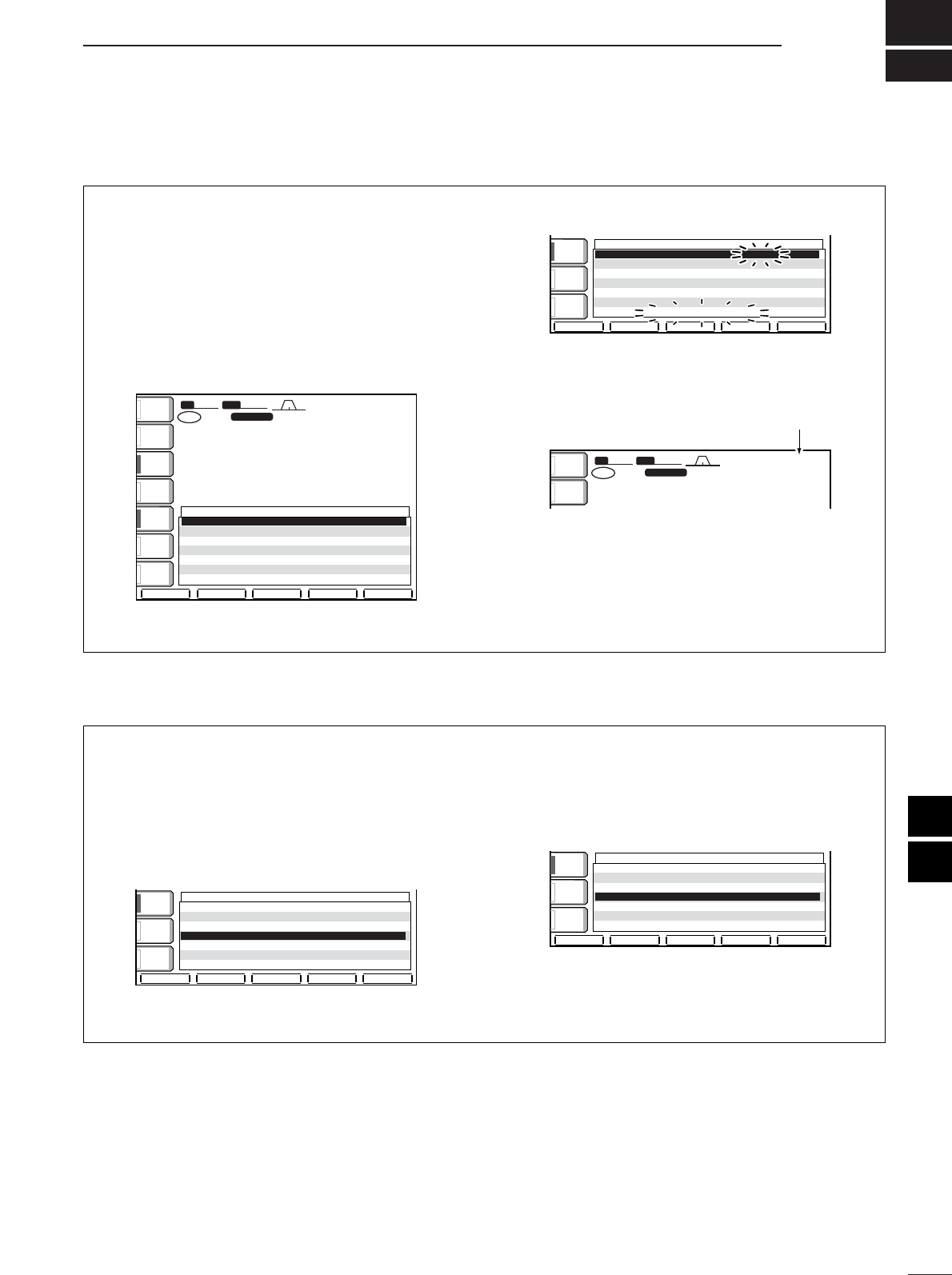
11
90
CLOCK AND TIMERS
10
11
■Setting the current time
The transceiver has a built-in 24-hour clock with
power-off and power-on timer functions. This is useful
when logging QSO’s and so on. The clock indication
is always displayed except after pushing [F-INP].
qPush [EXIT/SET] several times to close a multi-
function screen, if necessary.
wPush [EXIT/SET] for 1 sec. then [(F-4)TIME] to
enter timer set mode.
ePush [(F-1)Y] to select the Time (Now) item.
rSet the current time using the tuning dial.
•“TIME–set Push [SET]” blinks.
tPush [(F-4)SET] to enter the set time.
•Push [EXIT/SET] to cancel the setting.
yPush [EXIT/SET] twice to exit timer set mode.
SFTSFT 0
FIL2FIL2
USBUSB
qt:wr
TXTX
USBUSB
qr.qot.pp
14.100.0014.100.00
1
VFOVFO
BWBW 2.4k2.4k
ANTANT
1
METERMETER
Po
qt:wr
Set time appears.
TIME SETTIME SET
éè
TimeTime(Now)(Now) 15:2415:24
CLOCK2CLOCK2FunctionFunction ONON
CLOCK2CLOCK2OffsetOffset 0:000:00
TimerTimerFunctionFunction ONON
Power-ONPower-ONTimerTimerSetSet 0:000:00
Power-OFFPower-OFFPeriodPeriod 60min60min
TIME-setTIME-setPushPush[SET][SET]
SETSET
COMPCOMP
OFFOFF
WIDEWIDE
AGCAGC
MIDMID
VOXVOX
OFFOFF
SFTSFT 0
FIL2FIL2
USBUSB
qw:pp
TXTX
VFOVFO USBUSB
USBUSB
USBUSB
FIL2FIL2
qr.qot.pp
qr.wpt.pp
14.100.0014.100.00
14.100.0014.100.00
1
1
VFOVFO
BWBW 2.4k2.4k
TIME SETTIME SET
éè
TimeTime(Now)(Now) 12:0012:00
CLOCK2CLOCK2FunctionFunction ONON
CLOCK2CLOCK2OffsetOffset 0:000:00
TimerTimerFunctionFunction ONON
Power-ONPower-ONTimerTimerSetSet 0:000:00
Power-OFFPower-OFFPeriodPeriod 60min60min
ANTANT
1
COMPCOMP
OFFOFF
WIDEWIDE
METERMETER
PoPo
P.AMPP.AMP
1
AGCAGC
MIDMID
ATTATT
OFFOFF
VOXVOX
OFFOFF
qw:pp
■Timer function activity
The timer functions can be switched ON and OFF
qPush [EXIT/SET] several times to close a multi-
function screen, if necessary.
wPush [EXIT/SET] for 1 sec. then [(F-4)TIME] to
enter timer set mode.
ePush [(F-1)Y] or [(F-2)Z] to select the Timer Func-
tion item.
rSelect the timer function activity using the tuning
dial.
ON : Activates the timer functions when [POWER]
is pushed momentarily. (default)
OFF : Deactivates the timer functions even when
[POWER] is pushed momentarily.
tPush [EXIT/SET] twice to exit timer set mode.
TIME SETTIME SET
éè
TimeTime(Now)(Now) 15:2415:24
CLOCK2CLOCK2FunctionFunction ONON
CLOCK2CLOCK2OffsetOffset 0:000:00
TimerTimerFunctionFunction OFFOFF
Power-ONPower-ONTimerTimerSetSet 19:3019:30
Power-OFFPower-OFFPeriodPeriod 60min60min
SETSET
COMPCOMP
OFFOFF
WIDEWIDE
AGCAGC
MIDMID
VOXVOX
OFFOFF
TIME SETTIME SET
éè
TimeTime(Now)(Now) 15:2415:24
CLOCK2CLOCK2FunctionFunction ONON
CLOCK2CLOCK2OffsetOffset 0:000:00
TimerTimerFunctionFunction ONON
Power-ONPower-ONTimerTimerSetSet 0:000:00
Power-OFFPower-OFFPeriodPeriod 60min60min
COMPCOMP
OFFOFF
WIDEWIDE
AGCAGC
MIDMID
VOXVOX
OFFOFF
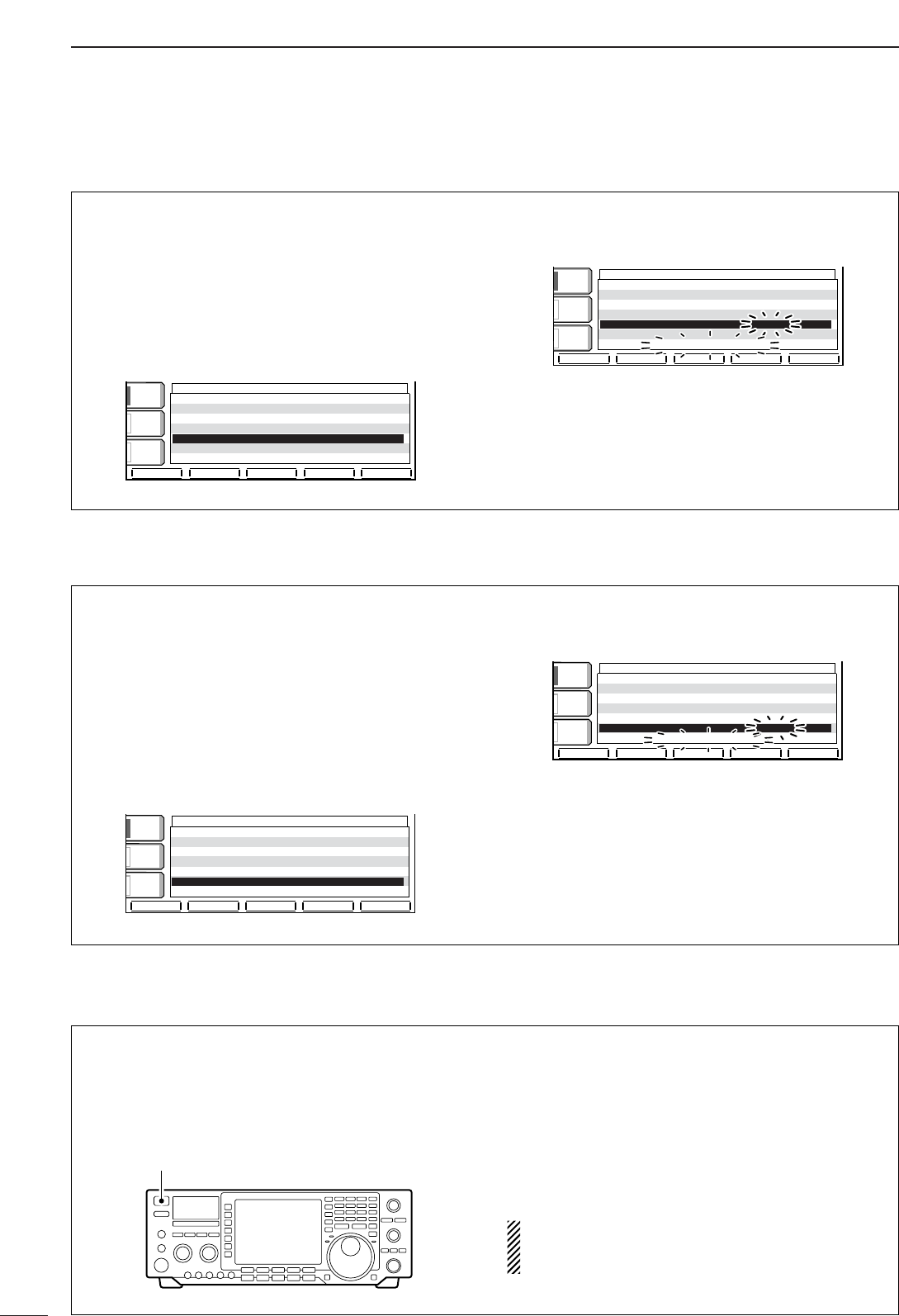
91
11 CLOCK AND TIMERS
■Setting power-off period
The transceiver can be set to turn OFF automatically
after being activated via the power-on timer. The
power-off period can be set to 5–120 min. in 5 min.
steps.
qPush [EXIT/SET] several times to close a multi-
function screen, if necessary.
wPush [EXIT/SET] for 1 sec. then [(F-4)TIME] to
enter timer set mode.
ePush [(F-2)Z] to select the Power-OFF Period
item.
rSet the desired power-off time using the tuning
dial.
•“TIMER – set Push [SET]” blinks.
tPush [(F-4)SET] to enter the set time.
•Push [EXIT/SET] to cancel the setting.
yPush [EXIT/SET] twice to exit timer set mode.
TIME SETTIME SET
éè
SETSET
TimeTime(Now)(Now) 15:2415:24
CLOCK2CLOCK2FunctionFunction ONON
CLOCK2CLOCK2OffsetOffset 0:000:00
TimerTimerFunctionFunction ONON
Power-ONPower-ONTimerTimerSetSet 19:3019:30
Power-OFFPower-OFFPeriodPeriod 45min45min
TIMER-setTIMER-setPushPush[SET][SET]
COMPCOMP
OFFOFF
WIDEWIDE
AGCAGC
MIDMID
VOXVOX
OFFOFF
TIME SETTIME SET
éè
TimeTime(Now)(Now) 15:2415:24
CLOCK2CLOCK2FunctionFunction ONON
CLOCK2CLOCK2OffsetOffset 0:000:00
TimerTimerFunctionFunction ONON
Power-ONPower-ONTimerTimerSetSet 19:3019:30
Power-OFFPower-OFFPeriodPeriod 60min60min
COMPCOMP
OFFOFF
WIDEWIDE
AGCAGC
MIDMID
VOXVOX
OFFOFF
■Timer operation
qPreset the power-on time and power-off period as
described previously.
wPush [POWER] momentarily to turn the timer func-
tion ON.
•The [POWER] light lights when the timer function is
ON.
ePush [POWER] for 1 sec. to turn the power OFF.
•The [POWER] light lights continuously.
rWhen the set time arrives, the power is automati-
cally turned ON.
tThe transceiver emits 10 beeps and turns OFF
after the power-off period elapses.
•The [POWER] light blinks while beeping.
•Push [POWER] momentarily to cancel the power-off
timer, if desired.
The timer function in timer set mode must be
turned ON to enable the timer operation. See page
97 for details.
[POWER]
■Setting power-on time
The transceiver can be set to turn ON automatically at
a specified time.
qPush [EXIT/SET] several times to close a multi-
function screen, if necessary.
wPush [EXIT/SET] for 1 sec. then [(F-4)TIME] to
enter timer set mode.
ePush [(F-1)Y] or [(F-2)Z] to select the Power-ON
Timer Set item.
rSet the desired power-on time using the tuning
dial.
•“TIMER–set Push [SET]” blinks.
tPush [(F-4)SET] to enter the set time.
•Push [EXIT/SET] to cancel the setting.
yPush [EXIT/SET] twice to exit timer set mode.
TIME SETTIME SET
éè
TimeTime(Now)(Now) 15:2415:24
CLOCK2CLOCK2FunctionFunction ONON
CLOCK2CLOCK2OffsetOffset 0:000:00
TimerTimerFunctionFunction ONON
Power-ONPower-ONTimerTimerSetSet 19:3019:30
Power-OFFPower-OFFPeriodPeriod 60min60min
TIMER-setTIMER-setPushPush[SET][SET]
SETSET
COMPCOMP
OFFOFF
WIDEWIDE
AGCAGC
MIDMID
VOXVOX
OFFOFF
TIME SETTIME SET
éè
TimeTime(Now)(Now) 15:2415:24
CLOCK2CLOCK2FunctionFunction ONON
CLOCK2CLOCK2OffsetOffset 0:000:00
TimerTimerFunctionFunction ONON
Power-ONPower-ONTimerTimerSetSet 0:000:00
Power-OFFPower-OFFPeriodPeriod 60min60min
COMPCOMP
OFFOFF
WIDEWIDE
AGCAGC
MIDMID
VOXVOX
OFFOFF
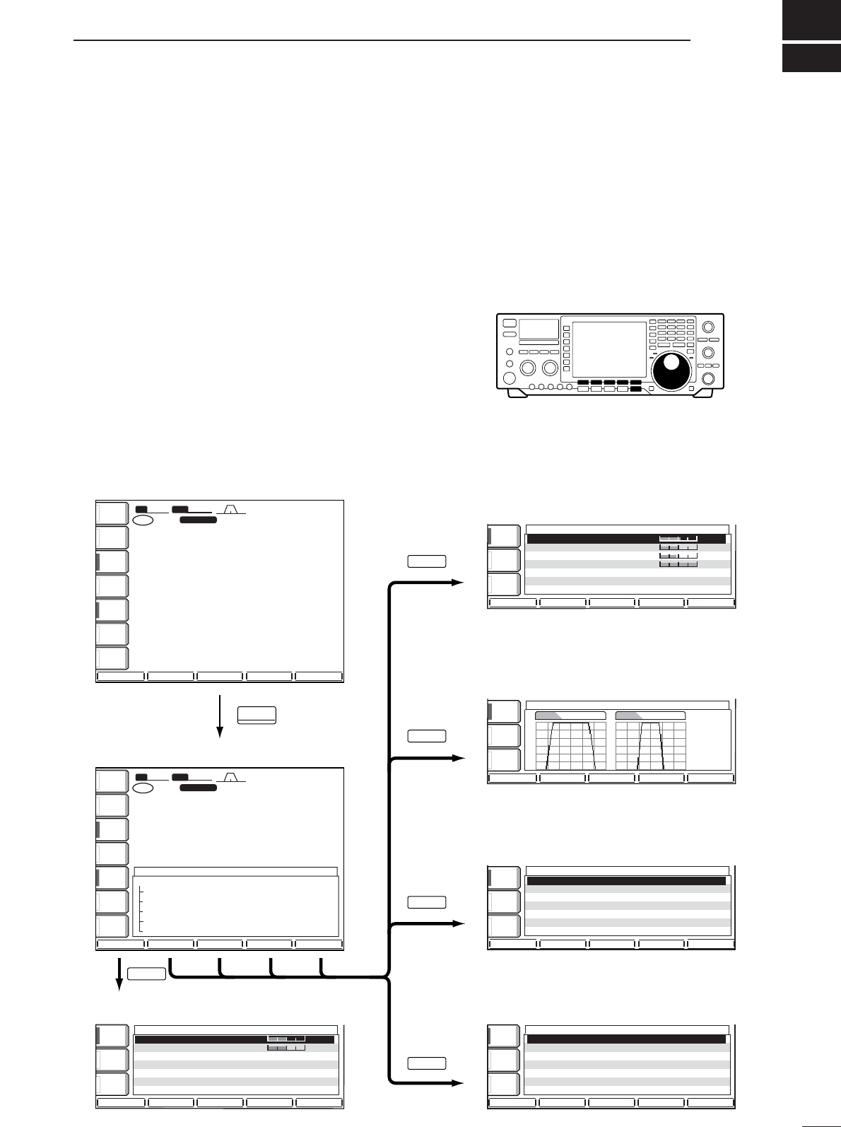
12
92
SET MODE
■Set mode description
Set mode is used for programming infrequently
changed values or conditions of functions. This trans-
ceiver has a level set mode, display set mode, timer
set mode and miscellaneous (others) set mode.
•Set mode operation
qPush [EXIT/SET] several times to close a multi-
function screen, if necessary.
wPush [EXIT/SET] for 1 sec. to select the set mode
menu screen.
ePush [(F-1)LEVEL], [(F-2)DISP], [(F-3)DSP], [(F-
4)TIME] or [(F-5)OTHERS] to enter the desired set
mode.
rFor display or miscellaneous (others) set mode,
push [(F-5)WIDE] to toggle wide and normal
screen.
tPush [(F-1)Y] or [(F-2)Z] to select the desired item.
ySet the desired condition using the tuning dial.
•Push [(F-3)DEF] for 1 sec. to select a default condition
or value.
uFor timer set mode, push [(F-4)SET] to enter the set
time.
iPush [EXIT/SET] twice to exit the set mode.
• Display set mode (p. 95)
• Level set mode (p. 93)
• Start up screen
• Set mode menu screen
• DSP set mode (p. 96)
• Timer set mode (pgs. 91, 97)
• Miscellaneous (others) set mode (p. 98)
SFTSFT 0
FIL2FIL2
CWCW
TXTX
VFOVFO USBUSB
USBUSB
USBUSB
FIL2FIL2
qr.qot.pp
qr.wpt.pp
14.100.0014.100.00
14.100.0014.100.00
1
1
VFOVFO
BWBW 2.4k2.4k
USBUSB
14.100.0014.100.00
1
SET MODESET MODE
LEVEL LEVEL
SETSET
SSB Tx Tone (Bass)SSB Tx Tone (Bass) 0
SSB Tx Tone (Treble)SSB Tx Tone (Treble) 0
SSB TBW (WIDE)SSB TBW (WIDE) L100100
SSB TBW (WIDE)SSB TBW (WIDE) H29002900
SSB TBW (MID)SSB TBW (MID) L300300
SSB TBW (MID)SSB TBW (MID) H27002700
SSB TBW (NAR)SSB TBW (NAR) L500500
OTHERS OTHERS
SETSET
TIME TIME
SETSET
DISPLAY DISPLAY
SETSET
SCOPESCOPE VOICEVOICE KEYERKEYER MEMORYMEMORY SCANSCAN
LEVELLEVEL DISPDISP DSPDSP TIMETIME OTHERSOTHERS
éèDEFDEF éèDEFDEF WIDEWIDE
éèDEFDEF WIDEWIDE
SSB-FILSSB-FIL CW-FILCW-FIL
éè
DSP FILTER SETDSP FILTER SET
SHARPSHARPSSBSSB
SHARPCW
METERMETER
PoPo
P.AMPP.AMP
1
ATTATT
0FF0FF
BK-INBK-IN
OFFOFF
1/41/4
OFFOFF
AGCAGC
MIDMID
ANTANT
1
EXIT/SET
Push
for 1 sec.
SFTSFT 0
FIL2FIL2
CWCW
TXTX
VFOVFO USBUSB
USBUSB
FIL2FIL2
qr.qot.pp
qr.wpt.pp
14.100.0014.100.00
1
VFOVFO
BWBW 2.4k2.4k
METERMETER
PoPo
P.AMPP.AMP
1
ATTATT
0FF0FF
BK-INBK-IN
OFFOFF
1/41/4
OFFOFF
AGCAGC
MIDMID
ANTANT
1
BK-INBK-IN
OFFOFF
1/41/4
OFFOFF
AGCAGC
MIDMID
BK-INBK-IN
OFFOFF
1/41/4
OFFOFF
AGCAGC
MIDMID
BK-INBK-IN
OFFOFF
1/41/4
OFFOFF
AGCAGC
MIDMID
BK-INBK-IN
OFFOFF
1/41/4
OFFOFF
AGCAGC
MIDMID
BK-INBK-IN
OFFOFF
1/41/4
OFFOFF
AGCAGC
MIDMID
F-1
F-2
F-3
F-4
F5
qw:pp
qw:pp
qw:pp
qw:pp
SET MODE MENUSET MODE MENU
LEVEL LEVEL TX Tone,Monitor,Side Tone etcTX Tone,Monitor,Side Tone etc
DISP Bright,Contrast,Style,Font etc DISP Bright,Contrast,Style,Font etc
DSP DSP DSP Filter TypeDSP Filter Type
TIME Clock/Timer TIME Clock/Timer
OTHERS OTHERS Other Set ModeOther Set Mode
CalibrationCalibrationMarkerMarker OFFOFF
Beep(Confirmation)Beep(Confirmation) ONON
Beep(BandBeep(BandEdge)Edge) ONON
RF/SQLRF/SQLControlControl RF+SQLRF+SQL
QuickQuickDualwatchDualwatch ONON
QuickQuickSPRITSPRIT ONON
FMFMSPLITSPLITOffset(HF)Offset(HF) -0.100MHz-0.100MHz
TimeTime(Now)(Now) 12:0012:00
CLOCK2 FunctionCLOCK2 Function ONON
CLOCK2 OffsetCLOCK2 Offset 0:000:00
Timer FunctionTimer Function ONON
Power-ONPower-ONTimerTimerSetSet 0:000:00
Power-OFFPower-OFFPeriodPeriod 60min60min
Contrast(LCD) 60%
Bright(LCD) 50%
Horizon 4
Backlight(Switches) 8
DisplayType A
DisplayFont Basic1
MemoryName ON

93
12 SET MODE
■Level set mode
SSSSBB TTxx TToonnee ((BBaassss))
This item adjusts the bass level of the transmit audio
tone in SSB mode from –5 dB to +5 dB in 1 dB steps.
0dB
0 dB (default)
SSSSBB TTxx TToonnee ((TTrreebbllee))
This item adjusts the treble level of the transmit audio
tone in SSB mode from –5 dB to +5 dB in 1 dB steps.
0dB
0 dB (default)
SSSSBB TTBBWW ((WWIIDDEE)) LL
These items set the transmission passband width for
wide setting by selecting the lower and higher fre-
quencies.
Lower freq. : 100 (default), 300 and 500 Hz
100
100 Hz (default)
SSSSBB TTBBWW ((WWIIDDEE)) HH
These items set the transmission passband width for
wide setting by selecting the lower and higher fre-
quencies.
Higher freq.: 2500, 2700 and 2900 Hz (default)
2900
2900 Hz (default)
SSSSBB TTBBWW ((MMIIDD)) LL
These items set the transmission passband width for
middle setting by selecting the lower and higher fre-
quencies.
Lower freq. : 100, 300 (default) and 500 Hz
300
300 Hz (default)
SSSSBB TTBBWW ((MMIIDD)) HH
These items set the transmission passband width for
middle setting by selecting the lower and higher fre-
quencies.
Higher freq.: 2500, 2700 (default) and 2900 Hz
2700
2700 Hz (default)
SSSSBB TTBBWW ((NNAARR)) LL
These items set the transmission passband width for
narrow setting by selecting the lower and higher fre-
quencies.
Lower freq. : 100, 300 and 500 Hz (default)
500
500 Hz (default)

94
12
SET MODE
■Level set mode (continued)
SSSSBB TTBBWW ((NNAARR)) HH
These items set the transmission passband width for
narrow setting by selecting the lower and higher fre-
quencies.
Lower freq. : 2500 (default), 2700 and 2900 Hz
2500
2500 Hz (default)
MMoonniittoorr LLeevveell
This item adjusts the transmit IF signal monitor level
from 0% to 100% in 1% steps.
See p. 69 for details.
50%
50% (default)
SSiiddee TToonnee LLeevveell
This item adjusts the CW side tone level from 0% to
100% in 1% steps.
See p. 69 for details.
50%
50% (default)
BBeeeepp LLeevveell
This item adjusts the volume level for confirmation
beep tones from 0% to 100% in 1% steps. When
beep tones are turned OFF, this setting has no effect.
50%
50% (default)
BBeeeepp LLeevveell LLiimmiitt
This item allows you to set a maximum volume level
for confirmation beep tones. Confirmation beep tones
are linked to the [AF] control until a specified volume
level is reached — further rotation of the [AF] control
will not increase the volume of the beep tones.
OONN
Beep level is limited with
[AF] (default)
OOFFFF
Beep level is linked to [AF]
SSiiddee TToonnee LLeevveell LLiimmiitt
This item allows you to set a maximum volume level
for CW side tones. CW side tones are linked to the
[AF] control until a specified volume level is reached
—further rotation of the [AF] control will not increase
the volume of the CW side tones.
OONN
CW side tone level is limited
with [AF] (default)
OOFFFF
CW side tone level is linked
to [AF]
95
12 SET MODE
■Display set mode
To adjust the LCD contrast or backlight, wait until
the LCD becomes stable (10 min. or more after turn-
ing power ON). This is an inherent characteristic of
LCDs and LCD backlights and does not indicate a
transceiver malfunction.
CCoonnttrraasstt ((LLCCDD))
This item adjusts the contrast of the LCD from 0% to
100% in 1% steps.
60%
60% (default)
BBaacckklliigghhtt ((LLCCDD))
This item adjusts the brightness of the LCD from 0%
to 100% in 1% steps.
50%
50% (default)
HHoorriizzoonn
This item adjusts the horizontal position of the LCD
from 1 to 8.
4
Horizontal position is 4. (default)
BBaacckklliigghhtt((SSwwiittcchheess))
This item adjusts the brightness of the switches from
1 to 8.
8
Backlight level is 8. (Maximum; default)
DDiissppllaayy TTyyppee
This item sets the LCD screen type. There are 8 se-
lectable types: A, B, C, D, E, F, G and H.
AA
A-type LCD screen (default)
DDiissppllaayy FFoonntt
This item sets the font of the frequency readouts.
There are 7 selectable fonts: Basic1, Basic2, Pop,
7seg (7 segment numeral), Italic 1, Italic 2 and Clas-
sic.
IIttaalliicc22
Italic 2 font (default)
MMeemmoorryy NNaammee
This item sets the memory name indication ON and
OFF.
See p. 80 for details.
OONN
Memory name is displayed.
(default)
OOFFFF
Memory name is not dis-
played.
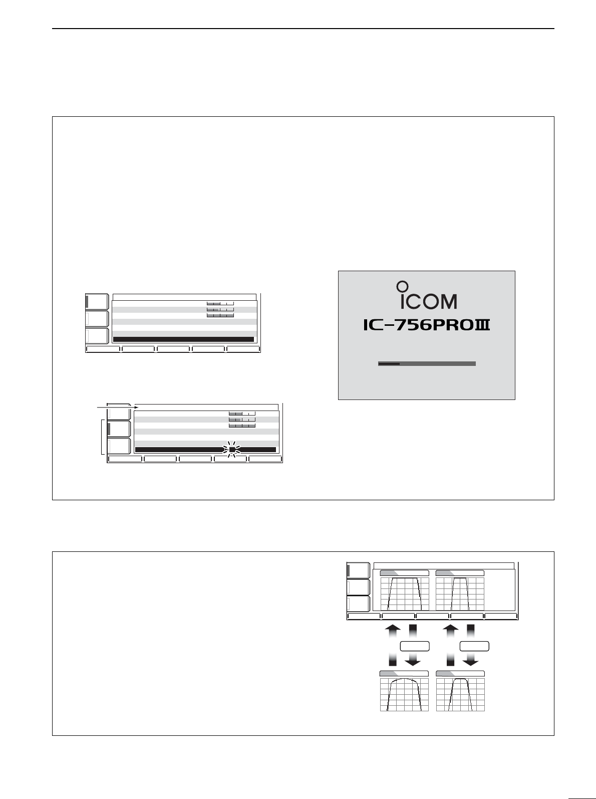
96
12
SEST MODE
MMyy CCaallll
Your call sign, etc. can be displayed in the opening
screen when turning power ON. Up to 10 characters
can be programmed.
Capital letters, numerals, some symbols (– / .) and
spaces can be used.
qPush [EXIT/SET] several times to close a multi-
function screen, if necessary.
wPush [EXIT/SET] for 1 sec. then [(F-2)DISP] mo-
mentarily to select the display set mode screen.
ePush [(F-2)Z] several times to select the ‘My Call’
item.
rPush [(F-4)EDIT] to edit.
•Acursor appears and blinks.
tInput the desired character by rotating the tuning
dial or by pushing the band key for number input.
•Push [ABC] to select capital letters.
•Push [123] or [etc] to toggle numerals and symbols.
•Push [(F-1)Ω] or [(F-2)≈] for cursor movement.
•Push [(F-3)DEL] to delete the selected character.
•Push [(F-4)SPACE] to input a space.
yPush [EXIT/SET] to input the set name.
•The cursor disappears.
uPush [EXIT/SET] to exit the set mode screen.
•Opening screen example
ja3yua
NOW CALIBRATING
DIGITAL SIGNAL PROCESSOR
PLEASE WAIT FOR 10sec.
çåDELDEL SPACESPACE WIDEWIDE
DISPLAY SET
123123
ABCABC
Character
group
keys
Selected
character Bright(LCD) 50%
Horizon 4
Backlight(Switches) 8
DisplayType A
DisplayFont Basic1
MemoryName ON
MyCall _A3YUA
ABCABC
éèEDIT WIDEWIDE
DISPLAY SET
VOXVOX
OFFOFF
COMPCOMP
OFFOFF
WIDEWIDE
AGCAGC
MIDMID
Bright(LCD) 50%
Horizon 4
Backlight(Switches) 8
DisplayType A
DisplayFont Basic1
MemoryName ON
MyCall JA3YUA
■Display set mode (continued)
■DSP filter set mode
To suit your operating style, the type of DSP filter
shape for SSB and CW can be selected.
qPush the [EXIT/SET] several times to close a
multi-function screen, if necessary.
wPush the [EXIT/SET] switch for 1 sec. to enter set
mode.
ePush the [(F-3)DSP] switch to enter the DSP filter
set mode.
rPush one of [(F2)SSB-FIL] or [(F4)CW-FIL] to se-
lect the desired DSP filter shape from sharp and
soft for SSB or CW mode, respectively.
tPush [ENTER/SET] twice to exit the DSP filter set
mode.
AGCAGC
MIDMID
BK-INBK-IN
OFFOFF
1/41/4
OFFOFF
DSP FILTER SET
SSBSSB SHARPSHARP CWCW SHARPSHARP
SSB-FILSSB-FIL CW-FILCW-FIL
SSBSSB SOFTSOFT CWCW SOFTSOFT
F-4
Push
F-2
Push

97
12 SET MODE
■Timer set mode
TTiimmee ((NNooww))
This item sets the current time for the built-in 24-hour
clock.
See p. 90 for details.
1155::0000
Push [(F-4)SET] to enter the time.
TTiimmeerr FFuunnccttiioonn
This item sets the timer functions ON and OFF.
When the power-ON timer or the power-OFF timer is
used, “ON” must be selected in this item.
See p. 90 for details.
OONN
The timer functions can be
operated. (default)
OOFFFF
The timer functions cannot
be operated.
CCLLOOCCKK22 FFuunnccttiioonn
This item turns the clock 2 indication ON and OFF.
The clock 2 is convenient to indicate the UTC or other
country’s local time, etc.
•ON : The clock 2 is displayed below the local time
indication.
•OFF : The clock 2 does not display.
OONN
The clock 2 is displayed
below the local tiem.
(default)
OOFFFF
The clock 2 does not dis-
play.
CCLLOOCCKK22 OOffffsseett
This item sets the desired off-set time period for the
clock 2 indication within –24:00 to +24:00 in 5 min.
steps.
•Pushing [(F-3)DEF] for 1 sec. to select the default value.
++ 99::0000
Rotate tuning dial to set the time.
PPoowweerr--OOFFFF ppeerriioodd
This item sets the power-off period for automatic shut-
down after the power-on timer has turned power ON.
See p. 90 for details.
6600mmiinn
Push [(F-4)SET] to enter the time.
PPoowweerr--OONN TTiimmeerr sseett
This item sets the power-on time.
See p. 90 for details.
1155::0000
Push [(F-4)SET] to enter the time.

98
12
SET MODE
■Miscellaneous (others) set mode
CCaalliibbrraattiioonn MMaarrkkeerr
This item is used for a simple frequency check of the
transceiver.
See p. 107 for calibration procedure.
Turn the calibration marker OFF after checking the
frequency of the transceiver.
OONN
Calibration marker ON
OOFFFF
Calibration marker OFF
(default)
BBeeeepp((CCoonnffiirrmmaattiioonn))
Abeep sounds each time a switch is pushed to con-
firm it. This function can be turned OFF for silent op-
eration.
The volume level can be set in level set mode. (p. 94)
OONN
Confirmation beep ON
(default)
OOFFFF
Confirmation beep OFF
BBeeeepp((BBaanndd EEddggee))
Abeep sounds when an operating frequency enters
or exits an amateur band. This functions independent
of the confirmation beep setting (above).
The volume level can be set in level set mode. (p. 94)
OONN
Band edge beep ON
(default)
OOFFFF
Band edge beep OFF
QQuuiicckk DDuuaallwwaattcchh
When this item is set to ON, pushing [DUALWATCH]
for 1 sec. sets the sub readout frequency to the main
readout frequency and activates dualwatch operation.
See p. 63 for details.
OONN
Quick dualwatch ON
(default)
OOFFFF
Quick dualwatch OFF
QQuuiicckk SSPPLLIITT
When this item is set to ON, pushing [SPLIT] for 1
sec. sets the sub readout frequency to the main read-
out frequency and activates split operation.
See p. 71 for details.
OONN
Quick split ON
(default)
OOFFFF
Quick split OFF
RRFF//SSQQLL CCoonnttrrooll
The [RF/SQL] control can be set as the RF/squelch
control (default), the squelch control only (RF gain is
fixed at maximum) or ‘Auto’ (RF gain control in SSB,
CW and RTTY; squelch control in AM and FM).
See pgs. 2, 30 for details.
RRFF++SSQQLL[RF/SQL] control as RF/squelch control
(default)
SSQQLL[RF/SQL] control as squelch control
AAUUTTOO[RF/SQL] control as RF gain control in SSB,
CW and RTTY; squelch control in AM and
FM

99
12 SET MMODE
■Miscellaneous (others) set mode (continued)
FFMM SSPPLLIITTOOffffsseett((5500MM))
This item sets the offset (difference between transmit
and receive frequencies) for the quick split function.
However, this setting is used for 50 MHz band FM
mode only, and is used to input the repeater offset for
the 50 MHz band.
The offset frequency can be set from –4 MHz to
+4 MHz in 1 kHz steps.
--00..550000MMHHzz
Minus 0.5 MHz offset
(default)
++44..000000MMHHzz
Plus 4.0 MHz offset
SSPPLLIITT LLOOCCKK
When this item is ON, the tuning dial can be used to
adjust the transmit frequency while pushing [XFC]
even while the lock function is activated.
See p. 70 for split frequency operation details.
OONN
Split lock function ON
OOFFFF
Split lock function OFF
(default)
TTuunneerr ((AAuuttoo SSttaarrtt))
The internal antenna tuner has an automatic start ca-
pability which starts tuning if the SWR is higher than
1.5–3:1.
When “OFF” is selected, the tuner remains OFF even
when the SWR is poor (1.5–3:1). When “ON” is se-
lected, automatic tune starts even when the tuner is
turned OFF.
OONN
Automatic tuner start
ON
OOFFFF
Automatic tuner start
OFF (default)
TTuunneerr ((PPTTTT SSttaarrtt))
Tuning of the internal antenna tuner can be started
automatically at the moment the PTT is pushed after
the operating frequency is changed (more than 1%
from last-tuned frequency).
OONN
Automatic PTT start
ON
OOFFFF
Automatic PTT start
OFF (default)
FFMM SSPPLLIITTOOffffsseett((HHFF))
This item sets the offset (difference between transmit
and receive frequencies) for the quick split function.
However, this setting is used for HF bands in FM
mode only and is used to input the repeater offset for
an HF band.
The offset frequency can be set from –4 MHz to
+4 MHz in 1 kHz steps.
--00..110000MMHHzz
Minus 0.1 MHz offset
(default)
--44..000000MMHHzz
Minus 4.0 MHz offset

100
12
SET MODE
■Miscellaneous (others) set mode (continued)
RRTTTTYY MMaarrkk FFrreeqquueennccyy
This item selects the RTTY mark frequency. RTTY
mark frequency is switched between 1275, 1615 and
2125 Hz.
22112255
2125 Hz RTTY mark
frequency (default)
11227755
1275 Hz RTTY mark
frequency
RRTTTTYY SShhiifftt WWiiddtthh
This item adjusts the RTTY shift width. There are 3
selectable values: 170, 200 and 425 Hz.
117700
170 Hz RTTY shift
frequency (default)
442255
425 Hz RTTY shift
frequency
RRTTTTYY KKeeyyiinngg PPoollaarriittyy
This item selects the RTTY keying polarity. Normal or
reverse keying polarity can be selected.
When reverse polarity is selected, Mark and Space
are reversed.
- Normal : Key open/close = Mark/Space
- Reverse : Key open/close = Space/Mark
NNoorrmmaall
Normal polarity (default)
RReevveerrssee
Reverse polarity
[[AANNTT]] SSwwiittcchh
You can set the antenna connector selection to auto-
matic, manual or non-selection (when using 1 an-
tenna only).
When “Auto” is selected, the antenna switch is acti-
vated and the band memory memorizes the selected
antenna. See p. 87 for details.
When “Manual” is selected, the antenna switch is ac-
tivated and selects an antenna manually.
When “OFF” is selected, the antenna switch is not ac-
tivated and does not function. The [ANT1] connector
is always selected in this case.
AAuuttooAntenna switch is activated and the
selection is automatically memorized.
(default)
MMaannuuaallAntenna switch is activated.
OOFFFFAntenna switch is deactivated and
[ANT1] is always selected.

101
12 SET MODE
■Miscellaneous (others) set mode (continued)
SSPPEEEECCHH LLaanngguuaaggee
When the optional UT-102
VOICE SYNTHESIZER UNIT
is
installed, you can select between English and Japan-
ese as the language.
See p. 104 for unit installation.
EEnngglliisshh
English announcement
(default)
JJaappaanneessee
Japanese announcement
SSPPEEEECCHH SSppeeeedd
When the optional UT-102
VOICE SYNTHESIZER UNIT
is
installed, you can select between faster or slower
synthesizer output.
See p. 104 for unit installation.
HHIIGGHH
Faster announcement
(default)
LLOOWW
Slower announcement
SSPPEEEECCHH SS--LLeevveell
When the optional UT-102
VOICE SYNTHESIZER UNIT
is
installed, you can have frequency, mode and signal
level announcement. Signal level announcement can
be deactivated if desired.
When “OFF” is selected, the signal level is not an-
nounced.
See p. 104 for unit installation.
OONN
Signal level announcement
(default)
OOFFFF
No signal level
announcement
MMeemmooppaadd NNuummbbeerrss
This item sets the number of memo pad channels
available. 5 or 10 memo pads can be set.
55
5 memo pads
(default)
1100
10 memo pads

102
12
SET MODE
■Miscellaneous (others) set mode (continued)
MMAAIINN DDIIAALL AAuuttoo TTSS
This item sets the auto tuning step function. When ro-
tating the tuning dial rapidly, the tuning step automat-
ically changes several times as selected.
There are 2 type of auto tuning steps: HIGH (Fastest)
and LOW (Faster).
HHIIGGHHAuto tuning step is turned ON.
Fastest tuning step during rapid rotation
(default)
LLOOWWAuto tuning step is turned ON.
Faster tuning step during rapid rotation
OOFFFFAuto tuning step is turned OFF.
SSSSBB//CCWW SSyynncchhrroonnoouuss TTuunniinngg
This item selects the displayed frequency shift func-
tion from ON and OFF.
When this function is activated, the receiving signal
can be kept to receive even when the operating mode
is changed between SSB and CW.
The frequency shifting value may differ according
to the CW pitch setting.
OONN
The displayed frequency
shifts when the operating
mode is changed between
SSB and CW.
OOFFFF
The displayed frequency
does not shift.
(default)
CCWW NNoorrmmaall SSiiddee
Selects the carrier point of CW mode from LSB and
USB.
LLSSBB
The carrier point is set to
LSB side.
(default)
UUSSBB
The carrier point is set to
USB side.
MMIICC UUpp//DDoowwnn SSppeeeedd
This item sets the rate at which frequencies are
scanned when the microphone [UP]/[DN] switches
are pushed and held. High or low can be selected.
HHIIGGHH
High speed (default,
50 tuning steps/sec.)
LLOOWW
Low speed
(25 tuning steps/sec.)
QQuuiicckk RRIITT//∂∂TTXX CClleeaarr
This item selects the RIT/∂TX frequency clearing in-
struction with the [CLEAR] switch.
OONN
Clears the RIT/∂TX fre-
quency when [CLEAR] is
pushed momentarily.
OOFFFF
Clears the RIT/∂TX fre-
quency when [CLEAR] is
pushed for 1 sec.
(default)
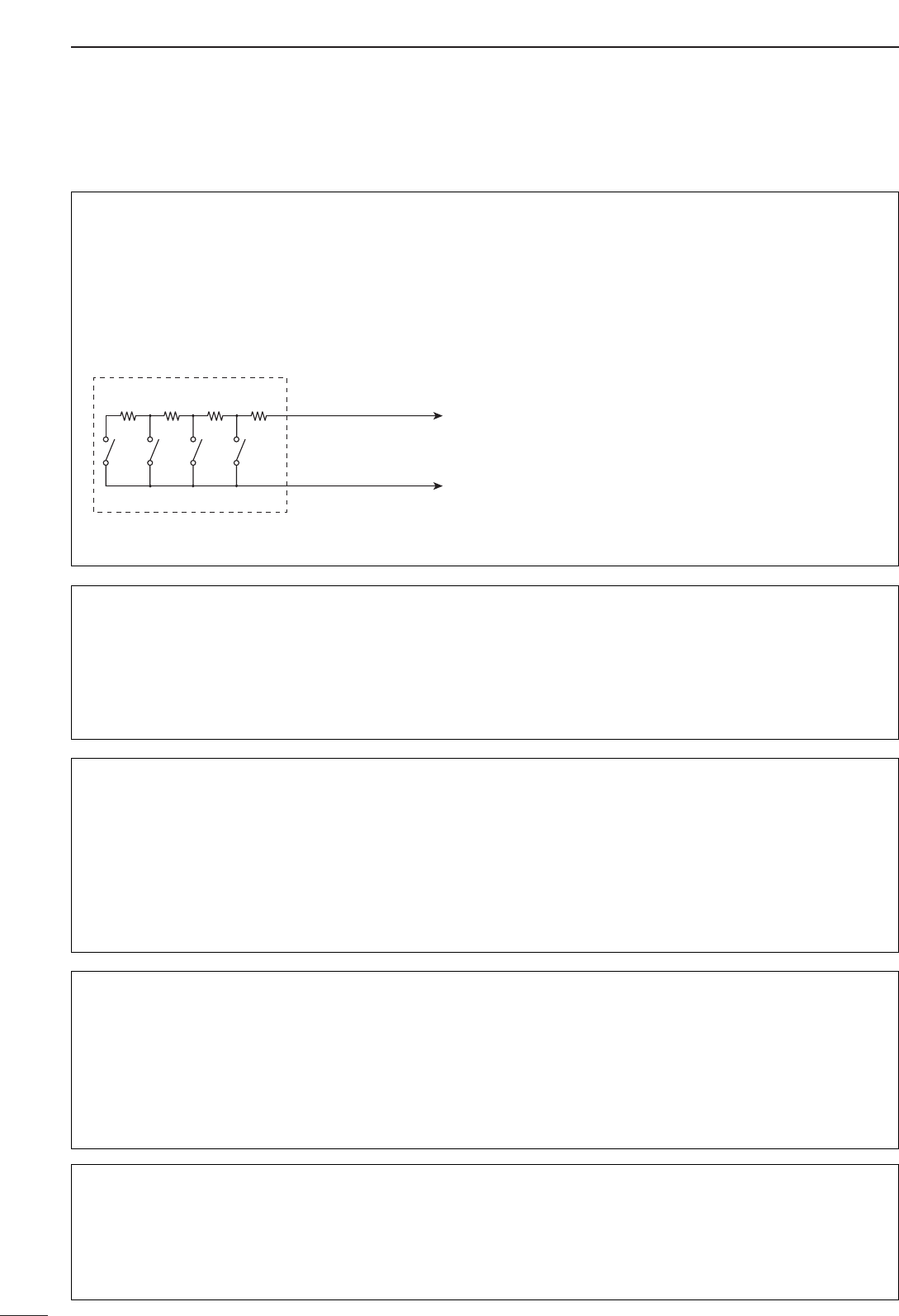
103
12 SSET MODE
■Miscellaneous (others) set mode (continued)
EExxtteerrnnaall KKeeyyppaadd
This item sets the external keypad capability and
function.
For your information
The following diagram shows the equivalent circuit of
an external keypad and connects to the pin 3 and
pin 7of the [MIC] connector (p. 18).
AAuuttooPushing one of external keypad
switches, transmits the desired voice
memory during a phone mode (SSB,
AM or FM), or memory keyer contents
during CW mode operation.
VVOOIICCEE PPLLAAYY((TTXX))
Pushing one of external keypad
switches, transmits the desired voice
memory contents during a phone
mode operation.
KKEEYYEERR SSEENNDDPushing one of external keypad
switches, transmits the desired keyer
memory contents during CW mode
operation.
OOFFFFExternal keypad does not function.
(default)
To [MIC] connector pin e
To [MIC] connector pin u
1.5kΩ
±5%
1.5kΩ
±5%
2.2kΩ
±5%
4.7kΩ
±5%
S1
(T1/M1)
S2
(T2/M2)
S3
(T3/M3)
S4
(T4/M4)
USER EXTERNAL KEYPAD
CCII--VV BBaauudd RRaattee
This item sets the data transfer rate. 300, 1200, 4800,
9600, 19200 bps and “Auto” are available.
When “Auto” is selected, the baud rate is automati-
cally set according to the connected controller or re-
mote controller.
AAuuttoo
Auto baud rate
(default)
1199220000
19200 bps
CCII--VV AAddddrreessss
To distinguish equipment, each CI-V transceiver has
its own Icom standard address in hexadecimal code.
The IC-756PROIII’s address is 6Eh.
When 2 or more IC-756PROIII’s are connected to an
optional CT-17
CI
-
VLEVEL CONVERTER
, rotate the tun-
ing dial to select a different address for each IC-
756PROIII in the range 01h to 7Fh.
66EEhh
Address of 6Eh
(default)
77FFhh
Address of 7Fh
CCII--VV TTrraannsscceeiivvee
Transceive operation is possible with the
IC-756PROIII
connected to other Icom HF transceivers or receivers.
When “ON” is selected, changing the frequency, op-
erating mode, etc. on the IC-756PROIII automatically
changes those of connected transceivers (or re-
ceivers) and vice versa.
OONN
Transceive ON
(default)
OOFFFF
Transceive OFF
CCII--VV wwiitthh IICC--773311
When connecting the IC-756PROIII to the IC-735 for
transceive operation, you must change the operating
frequency data length to 4 bytes.
•This item must be set to “ON” only when operating the
transceiver with the IC-735.
OONN
4 bytes of frequency data
OOFFFF
5 bytes of frequency data
(default)
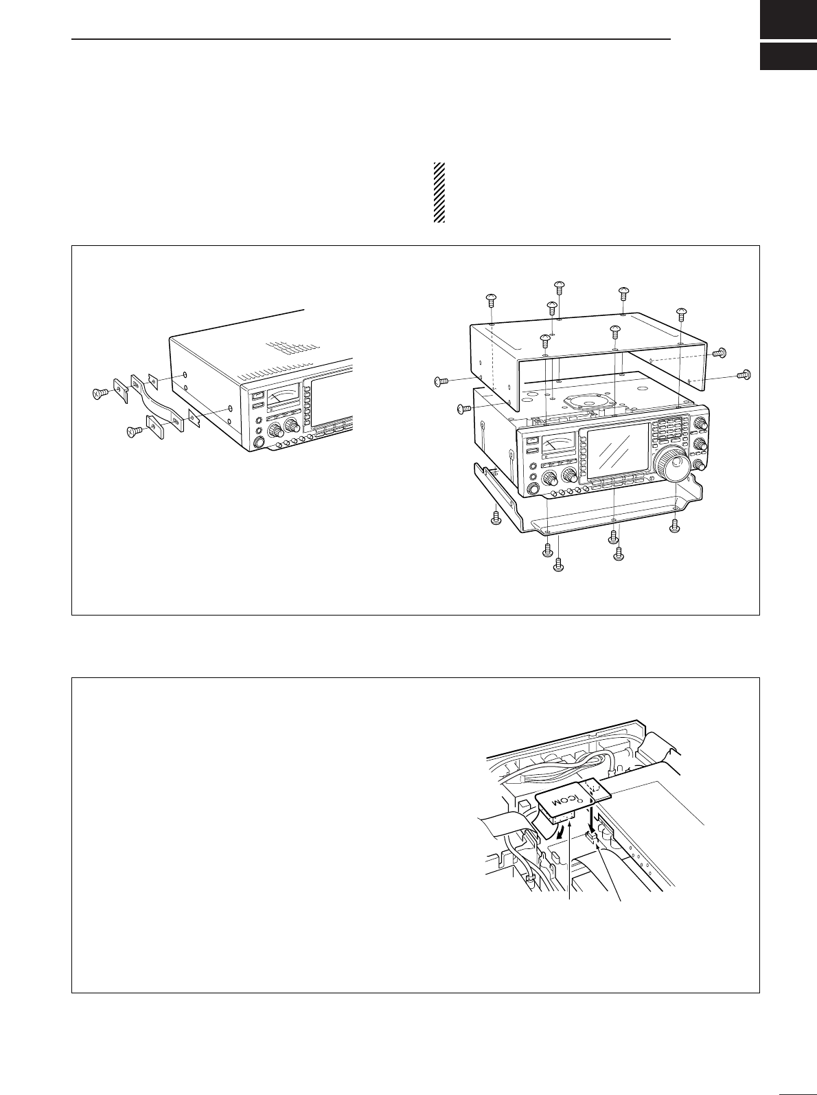
13
104
OPTION INSTALLATION
Follow the case and cover opening procedures shown
here when you want to install an optional unit or adjust
the internal units, etc.
CAUTION: DISCONNECT the DC power cable
from the transceiver before performing any work on
the transceiver. Otherwise, there is danger of elec-
tric shock and/or equipment damage.
■Opening the transceiver’s case
The UT-102 announces the accessed readout’s fre-
quency, mode, etc. (S-meter level can also be an-
nounced—p. 101) in a clear, electronically-generated
voice, in English (or Japanese).
➥Push [LOCK/SPEECH] for 1 sec. to announce the
frequency, etc.
qRemove the top and bottom covers as shown
above.
wRemove the protective paper attached to the bot-
tom of the UT-102 to expose the adhesive strip.
ePlug UT-102 into J3502 on the MAIN unit as
shown in the diagram at right.
rAdjust the trimmer SPCH to set the speech level if
desired. Refer to inside views on p. 108.
tReturn the top and bottom covers to their original
positions.
UT-102
J3502
UT-102
MAIN
unit
■UT-102
VOICE SYNTHESIZER UNIT
qRemove 2 screws from the left side of the trans-
ceiver to remove the carrying handle as shown
below.
wRemove 7 screws from the top of the transceiver
and 4 screws from the sides, then lift up the top
cover.
eTurn the transceiver upside down.
rRemove 6 screws from the bottom of the trans-
ceiver, then lift up the bottom cover.

14
105
MAINTENANCE
SCAN
■Troubleshooting
The following chart is designed to help you correct
problems which are not equipment malfunctions.
If you are unable to locate the cause of a problem or
solve it through the use of this chart, contact your near-
est Icom Dealer or Service Center.
PROBLEM POSSIBLE CAUSE SOLUTION REF.
RECEIVE POWERTRANSMIT
Power does not come on
when the [POWER] switch
is pushed.
No sounds come out from
the speaker.
Sensitivity is too low, and
only strong signals are au-
dible.
Received audio is unclear
or distorted.
The [ANT] switch does not
function
Transmitting is impossible.
Output power is too low.
No contact possible with
another station.
Transmit signal is unclear
or distorted.
Repeater cannot be ac-
cessed.
Programmed scan does
not stop.
Programmed scan does
not start.
Memory scan does not
start
Select memory scan does
not start
•Power cable is improperly connected.
•Fuse is blown.
•Volume level is too low.
•The squelch is closed.
•The transceiver is in transmitting condition.
•The antenna is not connected properly.
•The antenna for another band is selected.
•The antenna is not properly tuned.
•The attenuator is activated.
•Wrong operating mode is selected.
•PBT function is activated.
•Noise blanker is turned ON when receiving a
strong signal.
•Preamp is activated.
•The noise reduction is activated and the [NR]
control is too far clockwise.
•The antenna switch has not been activated.
•The operating frequency is not set to a ham
band.
•[RF POWER] is set too far counterclockwise
•[MIC GAIN] is set too far counterclockwise
•The antenna for another band is selected.
•The antenna is not properly tuned.
•RIT or ∂TX function is activated.
•Split frequency function and/or dualwatch are
activated.
•[MIC GAIN] is set too far clockwise
•Split frequency function is not activated.
•Programmed subaudible tone frequency is
wrong.
•Squelch is open.
•[RF/SQL] is assigned to RF gain control and
squelch is open.
•The same frequencies have been programmed
in scan edge memory channels P1 and P2.
•2 or more memory channels have not been
programmed.
•2 or more memory channels have not been
designated as select channels.
•Re-connect the DC power cable correctly.
•Check for the cause, then replace the fuse with
the spare one.
(Fuses are installed in the DC power cable and
the internal PA unit.)
•Rotate [AF] clockwise to obtain a suitable lis-
tening level.
•Turn [RF/SQL] to 10 o’clock position to open the
squelch.
•Push [TRANSMIT] to receive or check the
SEND line of an external unit, if desired.
•Re-connect to the antenna connector.
•Select an antenna suitable for the operating fre-
quency.
•Push [TUNER] for 1 sec. to manually tune the
antenna.
•Push [ATT] several times to select “ATT OFF.”
•Select a suitable operating mode.
•Push [PBT CLR] for 1 sec. to reset the function.
•Push [NB] to turn the noise blanker OFF.
•Push [P.AMP] once or twice to turn the function
OFF.
•Set the [NR] control for maximum readability.
•Set the antenna switch in set mode to “Auto” or
“Manual.”
•Set the frequency to a ham band.
•Rotate [RF POWER] clockwise.
•Set [MIC GAIN] to a suitable position.
•Select an antenna suitable for the operating fre-
quency.
•Push [TUNER] for 1 sec. to manually tune the
antenna.
•Push [RIT] or [∂TX] to turn the function OFF.
•Push [SPLIT] and/or [DUALWATCH] to turn the
function OFF.
•Set [MIC GAIN] to a suitable position.
•Push [SPLIT] to to turn the function ON
•Reset the frequency using set mode.
•Set [RF/SQL] to the threshold point.
•Reset [RF/SQL] control assignment and set it to
the threshold point.
•Program different frequencies in scan edge
memory channel P1 and P2.
•Program more than 2 memory channels.
•Designate more than 2 memory channels as se-
lect channels for the scan.
p. 16
p. 106
p. 1
p. 2
p. 1
—
pgs. 3,
87
p. 88
p. 3
p. 29
p. 60
p. 62
p. 3
p. 64
p. 87
p. 25
p. 2
p. 1
p. 3
p. 88
p. 6
pgs. 8,
63, 70
p. 1
p. 8
p. 52
p. 2
pgs. 2,
30, 98
p. 78
p. 78
pgs. 77,
85
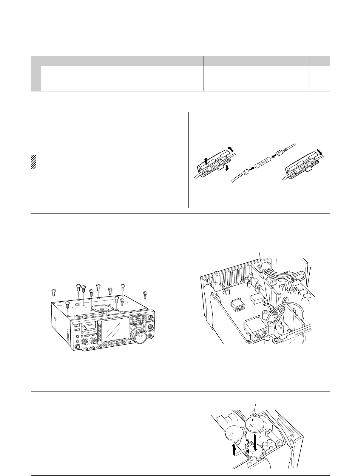
106
14
MAINTENANCE
■Fuse replacement
If a fuse blows or the transceiver stops functioning, try
to find the source of the problem, and replace the dam-
aged fuse with a new, rated fuse.
CAUTION:DISCONNECT the DC power cable
from the transceiver when changing a fuse.
The IC-756PROIII has 2 types of fuses installed for
transceiver protection.
•DC power cable fuses ................................ FGB 30 A
•Circuitry fuse ................................................FGB 5 A
DC POWER CABLE FUSE REPLACEMENT
30 A
fuse
■Clock backup battery replacement
The transceiver has a lithium backup battery
(CR2032) inside for clock and timer functions. The
usual life of the backup battery is approximately 2
years.
When the backup battery is exhausted, the trans-
ceiver transmits and receives normally but cannot re-
tain the current time.
See p. 108 for battery location.
CR2032
CIRCUITRY FUSE REPLACEMENT
The 13.8 V DC from the DC power cable is applied to
all units in the IC-756PROIII, except for the power
amplifier, through the circuitry fuse. This fuse is in-
stalled in the PA unit.
qRemove the top cover as shown on p. 104.
wRemove 11 screws from the PA shielding plate,
then remove the plate.
eReplace the circuitry fuse as shown in the diagram
below.
rReplace the PA shielding plate and top cover.
Circuitry fuse (FGB 5 A)
PROBLEM POSSIBLE CAUSE SOLUTION REF.
DISPLAY
The displayed frequency
does not change properly.
•The dial lock function is activated.
•Aset mode screen is selected.
•The internal CPU has malfunctioned.
•Push [LOCK/SPEECH] to turn the function OFF.
•Push [EXIT/SET] several times to exit the set
mode screen.
•Reset the CPU.
p. 64
pgs. 10,
92
p. 21
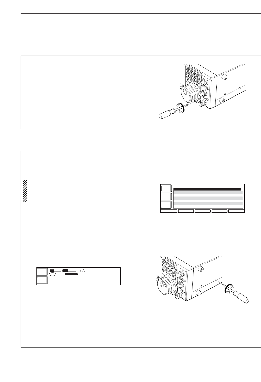
107
14 MAINTENANCE
■Tuning dial brake adjustment
The tension of the tuning dial may be adjusted to suit
your preference.
The brake adjustment screw is located on the right
side of the tuning dial. See the figure at right.
Turn the brake adjustment screw clockwise or coun-
terclockwise to obtain a comfortable tension level
while turning the dial continuously and evenly in one
direction.
Light
Heavy
■Frequency calibration (approximate)
Avery accurate frequency counter is required to cali-
brate the frequency of the transceiver. However, a
rough check may be performed by receiving radio
station WWV, or other standard frequency signals.
CAUTION: Your transceiver has been thor-
oughly adjusted and checked at the factory before
being shipped. You should not calibrate frequen-
cies, except for special reasons.
qPush [SSB] to select USB mode.
wPush [PBT CLR] for 1 sec. to clear the PBT set-
tings and make sure that the RIT/∂TX function is
not activated.
eSet the frequency to the standard frequency sta-
tion minus 1 kHz.
•When receiving WWV (10.000.00 MHz) as a standard
frequency, set the operating frequency for
9.999.00 MHz.
•Other standard frequencies can also be used.
rPush [EXIT/SET] several times to close a multi-
function screen, if necessary.
tPush [EXIT/SET] for 1 sec. to select the set mode
screen.
yPush [(F-5)OTHERS] to enter miscellaneous (oth-
ers) set mode.
uPush [(F-1)Y] several times to select the “Calibra-
tion marker” item.
iRotate the tuning dial clockwise to turn the calibra-
tion marker ON.
•Side tone may be heard.
oAdjust the calibration pot on the right side panel of
the transceiver for a zero beat with the received
standard signal as shown below.
•Zero beat means that two signals are exactly the same
frequency, resulting in a single tone being emitted.
!0 Rotate the tuning dial counterclockwise to turn the
calibration marker OFF.
!1 Push [EXIT/SET] twice to exit set mode.
DEFDEF WIDEWIDE
éè
AGCAGC
MIDMID
BK-INBK-IN
OFFOFF
1/41/4
OFFOFF
CalibrationCalibrationMarkerMarker ONON
Beep(Confirmation)Beep(Confirmation) ONON
Beep(BandBeep(BandEdge)Edge) ONON
RF/SQLRF/SQLControlControl RF+SQLRF+SQL
QuickQuickDualwatchDualwatch ONON
QuickQuickSPRITSPRIT ONON
FMFMSPLITSPLITOffset(HF)Offset(HF) -0.100MHz-0.100MHz
OTHERSOTHERSSETSET
SFTSFT 0
FIL2FIL2
USBUSB
qw:pp
TXTX
USBUSB
o.ooo.pp
14.100.0014.100.00
1
VFOVFO
BWBW 2.4k2.4k
ANTANT
1
METERMETER
PoPo
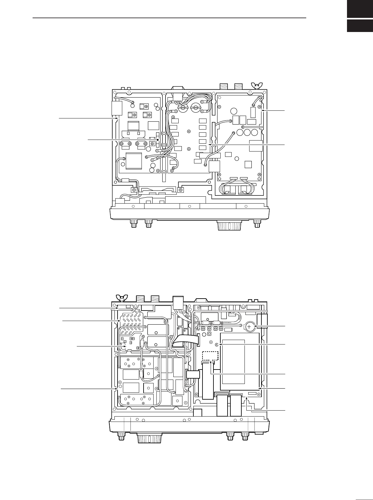
15
108
INTERNAL VIEWS
PA fuse (FGB 5 A)
PA unit
FILTER unit
Internal antenna
tuner
•Top view
BPF unit
PRE AMP unit
RF unit
PLL unit
Space for optional
voice synthesizer
(UT-102)
MAIN unit
Clock backup battery
DSP unit
SPCH
Optional voice
synthesizer level adj.
•Bottom view
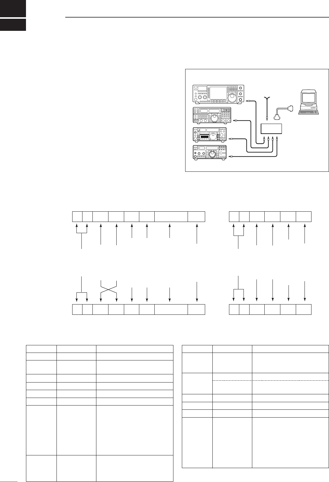
16
109
CONTROL COMMAND
•CI-V connection example
The transceiver can be connected through an optional
CT-17 CI-V LEVEL CONVERTER to a personal computer
equipped with an RS-232C port. The Icom Communi-
cations Interface-V (CI-V) controls the following func-
tions of the transceiver.
Up to 4 Icom CI-V transceivers or transceivers can be
connected to a personal computer equipped with an
RS-232C port. See p. 103 for setting the CI-V condi-
tion using set mode.
•Data format
The CI-V system can be operated using the following
data formats. Data formats differ according to com-
mand numbers. A data area or sub command is added
for some commands.
Controller to IC-756PROIII
FE FE 6E E0 Cn Sc Data area FD
Preamble
code (fixed)
Transceiver’s
default address
Controller’s
default address
Command number
(see the command table)
Sub command number
(see command table)
BCD code data for
frequency or memory
number entry
End of message
code (fixed)
OK message to controller
FE FE E0 6E FB FD
FE FE E0 6E FA FD
Preamble
code (fixed)
Controller’s
default address
Transceiver’s
default address
OK code
(fixed)
End of message
code (fixed)
NG message to controller
NG code
(fixed)
IC-756PROIII to controller
qwert y u
FE FE E0 6E Cn Sc Data area FD
qwert y u
■Remote jack (CI-V) information
9–15 V
DC
personal
computer
ct- 17
IC-756PROIII
mini-plug cable
•Command table
00 — Send frequency data
01 Same as Send mode data
command 06
02 — Read band edge frequencies
03 — Read operating frequency
04 — Read operating mode
05 — Set frequency data
06 00 Select LSB
01 Select USB
02 Select AM
03 Select CW
04 Select RTTY
05 Select FM
07 Select CW-R
08 Select RTTY-R
07 — Select VFO mode
B0 Exchange main and sub readouts
B1 Equalize main and sub readouts
C0 Turn the dualwatch OFF
07 C1 Turn the dualwatch ON
D0 Select main readout
D1 Select sub readout
08 — Select memory mode
0001–0101*1Select memory channel
*1P1=0100, P2=0101
09 — Memory write
0A — Memory to VFO
0B — Memory clear
0E 00 Scan stop
01 Programmed/memory scan start
02 Programmed scan start
03 ∂F scan start
12 Fine programmed scan start
13 Fine ∂F scan start
22 Memory scan start
23 Select memory scan start
Command Sub command Description Command Sub command Description

110
16
CONTROL COMMAND
•Command table (continued)
0E A1–A7 Set ∂F scan span (A1=±5 kHz,
A2=±10 kHz, A3=±20 kHz,
A4=±50 kHz, A5=±100 kHz,
A6=±500 kHz, A7=±1 MHz)
B0 Set as non-select channel
B1 Set as select channel
D0 Set scan resume OFF
D3 Set scan resume ON
0F 00 Turn the split function OFF
01 Turn the split function ON
10 00 Select 10 Hz (1 Hz) tuning step
01 Select 100 Hz tuning step
02 Select 1 kHz tuning step
03 Select 5 kHz tuning step
04 Select 9 kHz tuning step
05 Select 10 kHz tuning step
06 Select 12.5 kHz tuning step
07 Select 20 kHz tuning step
08 Select 25 kHz tuning step
11 00 Attenuator OFF
06 Attenuator ON (6 dB)
12 Attenuator ON (12 dB)
18 Attenuator ON (18 dB)
12 00 Select/read antenna selection
01 (00=ANT1, 01=ANT2 : Add 0 or 1
to turn [RX ANT] OFF or ON, re-
spectively.)
13 00 Announce with voice synthesizer
01 (00=all data; 01=frequency and
02 S-meter level; 02=receive mode)
14 01 + Level data [AF] level setting (0=max. CCW to
255=max. CW)
02 + Level data [RF] level setting (0=max. CCW to
255=11 o’clock)
03 + Level data [SQL] level setting (0=11 o’clock to
255=max. CW)
06 + Level data [NR] level setting (0=min. to
255=max.)
07 + Level data Inside [TWIN PBT] setting or IF
shift setting (0=max. CCW,
128=center, 255=max. CW)
08 + Level data Outside [TWIN PBT] setting
(0=max. CCW, 128=center,
255=max. CW)
09 + Level data [CW PITCH] setting (0=low pitch to
255=high pitch)
0A + Level data [RF POWER] setting (0=mini. to
255=max.)
0B + Level data [MIC GAIN] setting (0=mini. to
255=max.)
0C + Level data [KEY SPEED] setting (0=slow to
255=fast)
0D + Level data [NOTCH] setting (0=low freq. to
255=high freq.)
0E + Level data [COMP] setting (0=mini. to
255=max.)
0F + Level data [BK-IN DELAY] setting (0=short
delay to 255=long delay)
10 + Level data [BAL] level setting (0=max. CCW,
128=center, 255=max. CW)
12 + Level data [NB] level setting (0=mini. to
255=max.)
15 + Level data Monitor gain setting (0=0% to
255=100%)
14 16 + Level data VOX gain setting (0=0% to
255=100%)
17 + Level data Anti-VOX gain setting (0=0% to
255=100%)
18 + Level data LCD contrast setting (0=0% to
255=100%)
19 + Level data LCD bright setting (0=0% to
255=100%)
15 01 Read squelch condition
02 Read S-meter level
11 Read Po meter level
12 Read SWR meter level
13 Read ALC meter level
14 Read COMP meter level
16 02 Preamp (0=OFF; 1=preamp 1;
2=preamp 2)
12 AGC selection (1=Fast; 2=Mid;
3=Slow)
22 Noise blanker (0=OFF; 1=ON)
40 Noise reduction (0=OFF; 1=ON)
41 Auto notch (0=OFF; 1=ON)
42 Repeater tone (0=OFF; 1=ON)
43 Tone squelch (0=OFF; 1=ON)
44
Speech compressor (0=OFF; 1=ON)
45 Monitor (0=OFF; 1=ON)
46 VOX function (0=OFF; 1=ON)
47 Break-in (0=OFF; 1=semi break-
in; 2=full break-in)
48 Manual notch (0=OFF; 1=ON)
49 RTTY filter (0=OFF; 1=ON)
4F Twin peak filter (0=OFF; 1=ON)
50 Dial lock (0=OFF; 1=ON)
19 00 Read the transceiver ID
1A 00 Send/read memory contents (see
p. 112 for details)
01 Send/read band stacking register
contents (see p. 112 for details)
02 Send/read memory keyer con-
tents (see p. 112 for details)
03 Send/read the selected filter width
(0=50 Hz to 40/31=3600/2700 Hz)
04 Send/read the selected AGC time
constant (0=OFF, 1=0.1/0.3 sec. to
13=6.0/8.0 sec.)
0501 Send/read SSB TX Tone (Bass)
level (0 =min. to 10=max.)
0502 Send/read SSB TX Tone (Treble)
level (0=min. to 10=max.)
0503 Send/read MONITOR gain (0=min.
to 255=max.)
0504 Send/read CW side tone gain
(0=min. to 255=max.)
0505 Send/read CW side tone gain limit
(0=OFF, 1=ON)
0506 Send/read beep gain (0=min. to
255=max.)
0507 Send/read beep gain limit (0=OFF,
1=ON)
0508 Send/read LCD contrast (0=0% to
255=100%)
0509 Send/read LCD backlight (0=0% to
255=100%)
Command Sub command Description Command Sub command Description

111
16 CONTROL COMMAND
•Command table (continued)
1A 0539 Send/read memo pad numbers
(0=5 ch, 1=10 ch)
0540 Send/read main dial auto TS
(0=OFF, 1=Low, 2=High)
0541 Send/read mic. up/down speed
(0=Low, 1=High)
0542 Send/read CI-V transceive set
(0=OFF, 1=ON)
0543 Send/read CI-V 731 mode set
(0=OFF, 1=ON)
0544 Send/read TX spectrum scope set
(0=OFF, 1=ON)
0545 Send/read spectrum scope max.
hold set (0=OFF, 1=ON)
0546 Send/read voice auto monitor set
(0=OFF, 1=ON)
0547 Send/read cut number style
(0=Normal, 1=190→ANO,
2=190→ANT, 3=90→NO,
4=90→NT)
0548 Send/read count up trigger chan-
nel (1=M1, 2=M2, 3=M3, 4=M4)
0549 Send/read present number
(1–9999)
0550 Send/read CW keyer repeat time
(1=1 sec. to 60=60 sec.)
0551 Send/read CW keyer dot/dash
ratio (28=1:1:2.8 to 45=1:1:4.5)
0552 Send/read rise time (0=2 msec.,
1=4 msec., 2=6 msec., 3=8 msec.)
0553 Send/read paddle polarity
(0=Normal, 1=Reverse)
0554 Send/read keyer type (0=Straight,
1=Bug-key, 2=ELEC-Key)
0555 Send/read mic. up/down keyer set
(0=OFF, 1=ON)
0556 Send/read scan speed (0=low,
1=high)
0557 Send/read scan resume (0=OFF,
1=ON)
0558 Send/read VOX gain (0=0% to
255=100%)
0559 Send/read anti VOX gain (0=0% to
255=100%)
0560 Send/read VOX delay (0=0.0 sec.
to 20=2.0 sec.)
0561 Send/read RTTY filter bandwidth
(0=250 Hz, 1=300 Hz, 2=350 Hz,
3=500 Hz, 4=1 kHz)
0562 Send/read twin peak filter (0=OFF,
1=ON)
0563 Send/read timer functions (0=OFF,
1=ON)
0564 Send/read DSP filter type
(0=SSB: sharp; CW: sharp,
1=SSB: sharp; CW: soft,
2=SSB: soft CW: sharp,
3=SSB: soft CW: soft)
0565 Send/read quick RIT/∂TX clear
function (0=OFF, 1=ON)
0566 Send/read SSB/CW synchronous
tuning function (0=OFF, 1=ON)
0567 Send/read CW normal side set
(0=LSB, 1=USB)
1A 0510 Send/read LCD horizontal position
(0=1 to 7=8)
0511 Send/read switch backlight (0=1 to
7=8)
0512 Send/read display type (0=A, 1=B,
2=C, 3=D, 4=E, 5=F, 6=G, 7=H)
0513 Send/read display font (0=Basic1,
1=Basic2, 2=Pop, 3=7seg,
4=Italic1, 5=italic2, 6=Classic)
0514 Send/read memory name (0=OFF,
1=ON)
0515 Send/read my call setting (10-char-
acter: see p. 112)
0516 Send/read current time (0000 to
2359)
0517 Send/read power-ON timer set
(0000 to 2359)
0518 Send/read power-OFF period
(5=5 min. to 120=120 min. in
5min. step)
0519 Send/read calibration marker
(0=OFF, 1=ON)
0520 Send/read confirmation beep
(0=OFF, 1=ON)
0521 Send/read band edge beep
(0=OFF, 1=ON)
0522 Send/read RF/SQL control set
(0=Auto, 1=SQL, 2=RF+SQL)
0523 Send/read quick dualwatch set
(0=OFF, 1=ON)
0524 Send/read quick split set (0=OFF,
1=ON)
0525 Send/read FM split offset (HF)
–4.000 to +4.000 MHz
(see p. 112 for details)
0526 Send/read FM split offset (50 MHz)
–4.000 to +4.000 MHz
(see p. 112 for details)
0527 Send/read split lock set (0=OFF,
1=ON)
0528 Send/read tuner auto start set
(0=OFF, 1=ON)
0529 Send/read PTT tune set (0=OFF,
1=ON)
0530 Send/read antenna selection
(0=OFF, 1=Manual, 2=Auto)
0531 Send/read RTTY mark frequency
(0=1275 Hz, 1=1615 Hz,
2=2125 Hz)
0532 Send/read RTTY shift width
(0=170 Hz, 1=200 Hz, 2=425 Hz)
0533 Send/read RTTY keying polarity
(0=Normal, 1=Reverse)
0534 Send/read RTTY decode USOS
(0=OFF, 1=ON)
0535 Send/read RTTY decode new line
code (0=CR,LF,CR+LF,
1=CR+LF)
0536 Send/read speech language
(0=English, 1=Japanese)
0537 Send/read speech speed (0=slow,
1=fast)
0538 Send/read S-level speech (0=OFF,
1=ON)
Command Sub command Description Command Sub command Description
112
16
CONTROL COMMAND
•Command table (continued)
0568 Send/read external keypad type
(0=OFF, 1=Keyer send, 2=Voice
play (Tx), 3=Auto)
0569 Send/read NB level (0=0% to
255=100%)
0570 Send/read SSB transmit band-
width-WIDE (Low: 100 Hz, High:
2900 Hz)
0571 Send/read SSB transmit band-
width-MID (Low: 300 Hz, High:
2700 Hz)
0572 Send/read SSB transmit band-
width-NAR (Low: 500 Hz, High:
2500 Hz)
0573 Send/read clock2 function
(0=OFF, 1=ON)
0574 Send/read offset time for clock2
(240001=–24:00, 240000=+24:00)
0575 Send/read screen saver setting
(0=OFF, 1=15 min, 2=30 min,
3=60 min)
0576 Send/read RTTY TX USOS
(0=OFF, 1=ON)
06 Send/read DATA mode (0=OFF,
1=ON)
07 Send/read SSB transmit band-
width (0=Wide, 1=Middle, 2=Nar-
row)
1B 00 Set repeater tone frequency
01 Set tone squelch tone frequency
1C 00 Set the transceiver to receive or
transmit condition (0=Rx; 1=Tx)
01 Send/read tuner function (0=OFF,
1=ON, 2=Manual tune)
Command Sub command Description
•To send/read memory contents
When sending or reading memory contents, additional code
as follows must be added to appoint the memory channel.
➥Additional code: 0000–0101 (0100=P1, 0101=P2)
•Band stacking register
To send or read the desired band stacking register’s con-
tents, combined code of the frequency band and register
codes as follows are used.
For example, when sending/reading the oldest contents in
the 21 MHz band, the code “0703” is used.
•Frequency band code
•Register code
•Channel code for memory keyer
To send or read the desired memory keyer contents, the
channel and character codes as follows are used.
•Channel code
•Character’s code
•Character’s code for my call
•FM split frequency (HF/50 MHz) setting
The following data sequence is used when sending/reading
the FM split frequency setting.
1 kHz digit: 0–9
100 Hz digit: 0 (fixed)
100 kHz digit: 0–9
10 kHz digit: 0–9
10 MHz digit: 0 (fixed)
1 MHz digit: 0–4
Direction:
00=+ direction
01=– direction
q
0XXXXXX
we
0
r
Code Frequency band Frequency range (unit: MHz)
01 1.8 1.800000– 1.999999
02 3.5 3.400000– 4.099999
03 7 6.900000– 7.499999
04 10 9.900000–10.499999
05 14 13.900000–14.499999
06 18 17.900000–18.499999
07 21 20.900000–21.499999
08 24 24.400000–25.099999
09 28 28.000000–29.999999
10 50 50.000000–54.000000
11 GENE Other than above
Code Registered number
01 1 (latest)
02 2
03 3 (oldest)
Character ASCII code Description
0–9 30–39 Numerals
A–Z 41–5A Alphabetical characters
a–z 61–7A Alphabetical characters
space 20 Word space
/2FSymbol
?3FSymbol
,2CSymbol
.2ESymbol
^5Ee.g., to send
BT
, enter ^4254
✱2A Inserts contact number (can be
used for 1 channel only)
Code Channel number
01 M1
02 M2
03 M3
04 M4
Character ASCII code Description
0–9 30–39 Numerals
A–Z 41–5A Alphabetical characters
a–z 61–7A Alphabetical characters
space 20 Word space
–2DSymbol
.2ESymbol
/2FSymbol

17
113
SPECIFICATIONS
•General
•Frequency coverage :
Rx 0.030–60.000 MHz*1*2
Tx 1.800– 1.999 MHz*2
3.500– 3.999 MHz*2
7.000– 7.300 MHz*2
10.100–10.150 MHz*2
14.000–14.350 MHz*2
18.068–18.168 MHz*2
21.000–21.450 MHz*2
24.890–24.990 MHz*2
28.000–29.700 MHz*2
50.000–54.000 MHz*2
*1Some frequency bands are not guaranteed.
*2Depending on version.
•Mode : USB, LSB, CW, RTTY, AM, FM
•No. of memory channels : 101 (99 regular, 2 scan edges)
•Antenna connector : SO-239 ×2 and phono
(RCA; 50 Ω)
•Temperature range : –10˚C to +50˚C
; +14˚F to +122˚F
•Frequency stability : Less than ±0.5 ppm 1 min. after
power ON.
(–10 to +50˚C; +14 to
+122˚F)
•Frequency resolution : 1 Hz
•Power supply : 13.8 V DC ±15%
(negative ground)
•Power consumption :
Transmit Max. power 23 A
Receive Standby 3.0 A (typ.)
Max. audio 3.5 A (typ.)
•Dimensions : 340(W) ×111(H) ×285(D) mm
(projections not included) 133⁄8(W) ×43⁄8(H) ×117⁄32(D) in
•Weight (approx.) : 9.6 kg; 21 lb 3 oz
•ACC 1 connector : 8-pin DIN connector
•ACC 2 connector : 7-pin DIN connector
•CI-V connector : 2-conductor 3.5 (d) mm (1⁄8″)
•Display : 5-inch (diagonal) TFT color LCD
•Transmitter
•Output power (continuously adjustable):
SSB/CW/RTTY/FM Less than 5 to 100 W
AM Less than 5 to 40 W
•Modulation system :
SSB PSN modulation
AM Low power modulation
FM Phase modulation
•Spurious emission : 50 dB (HF bands)
60 dB (50 MHz band)
•Carrier suppression : 40 dB
•Unwanted sideband : 55 dB
suppression
•∂TX variable range : ±9.999 kHz
•Microphone connector : 8-pin connector (600 Ω)
•ELEC-KEY connector :
3-conductor 6.35(d) mm
(1⁄4″)
•KEY connector :
3-conductor 6.35(d) mm
(1⁄4″)
•SEND connector : Phono (RCA)
•ALC connector : Phono (RCA)
•Receiver
•Receive system : Triple conversion
superheterodyne system
•Intermediate frequencies :
1st 64.455 MHz
2nd 455 kHz
3rd 36 kHz
•Sensitivity (typical) :
SSB, CW, RTTY 0.16 µV (1.80–29.99 MHz)*1
(10 dB S/N) 0.13 µV (50.0–54.0 MHz)*2
AM (10 dB S/N) 13 µV (0.5–1.799 MHz)
2 µV (1.80–29.99 MHz)*1
1 µV (50.0–54.0 MHz)
FM (12 dB SINAD) 0.5 µV (28.0–29.99 MHz)*1
0.32 µV (50.0–54.0 MHz)*2
*1Pre-amp 1 is ON, *2Pre-amp 2 is ON
•Squelch sensitivity (Pre-amp: OFF):
SSB, CW, RTTY Less than 5.6 µV
FM Less than 1 µV
•Selectivity :
SSB, RTTY More than 2.4 kHz/–6 dB
(BW: 2.4 kHz) Less than 3.6 kHz/–60 dB
CW (BW: 500 Hz) More than 500 Hz/–6 dB
Less than 700 Hz/–60 dB
AM (BW: 6 kHz) More than 6.0 kHz/–6 dB
Less than 15.0 kHz/–60 dB
FM (BW: 15 kHz) More than 12.0 kHz/–6 dB
Less than 20.0 kHz/–60 dB
•Spurious and image : More than 70 dB
rejection ratio (except IF through on 50 MHz band)
•AF output power : More than 2.0 W at 10%
(at 13.8 V DC) distortion with an 8 Ωload
•RIT variable range : ±9.999 kHz
•PHONES connector : 3-conductor 6.35 (d) mm (1⁄4″)
•External SP connector : 2-conductor 3.5 (d) mm
(1⁄8″)/8 Ω
•Antenna tuner
•Matching impedance range:
HF bands 16.7 to 150 Ωunbalanced
(Less than VSWR 3:1)
50 MHz band 20 to 125 Ωunbalanced
(Less than VSWR 2.5:1)
•Minimum operating input : 8 W
power
•Tuning accuracy : VSWR 1.5:1 or less
•Insertion loss (after tuning) :Less than 1.0 dB
All stated specifications are typical and subject to change without no-
tice or obligation.
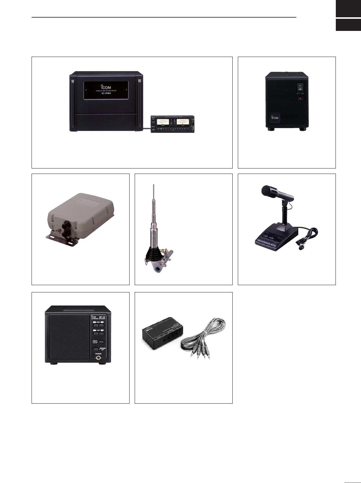
18
114
OPTIONS
IC-PW1 HF/50 MHz ALL BAND 1 kW LINEAR AMPLIFIER
Full-duty 1 kW linear amplifier including an automatic antenna tuner. Has
automatic tuning and band selection capability. Full break-in (QSK) oper-
ation is possible. The amplifier/power supply unit and the remote control
unit are separated.
AH-4 HF/50 MHz AUTOMATIC
ANTENNA TUNER
Specially designed to tune a long
wire antenna for portable or mobile
HF operation. The PTT tuner start
function provides simple operation.
•Input power rating: 120 W
AH-2b ANTENNA ELEMENT
A2.5 m long an-
tenna element for
mobile operation
with the AH-4.
•Frequency
coverage:
7–54 MHz bands
with the AH-4
SM-20 DESKTOP MICROPHONE
Unidirectional, electret microphone
for base station operation. Includes
[UP]/[DOWN] switches and a low
cut function.
SP-23 EXTERNAL SPEAKER
4 audio filters; headphone jack; can
connect to 2 transceivers.
•Input impedance: 8 Ω
•Max. input power: 5 W
CT-17 CI-V LEVEL CONVERTER
For remote transceiver control
using a personal computer. You
can change frequencies, operating
mode, memory channels, etc.
HM-36 HAND MICROPHONE
Hand microphone equipped with
[UP]/[DOWN] switches.
UT-102 VOICE SYNTHESIZER UNIT
Announces the receive frequency, mode
and S-meter level in a clear, electroni-
cally-generated voice, in English (or
Japanese).
PS-125 DC POWER SUPPLY
Light weight switching regulator
system power supply.
•Output voltage: 13.8 V DC
•Max. current drain: 25 A
•About DC power supply
The use of IC-756PROIII (#33, #34, #35, #38, #40) in com-
bination with the DC power supply complies with European
Harmonised Standard regulations under the conditions
listed below.
Conditions
•In combination with PS-125
•
About IC-PW1
LINEAR AMPLIFIER
The IC-PW1
LINEAR AMPLIFIER
does not comply with Euro-
pean Harmonised Standard regulations. Please do not use
this equipment within European countries.

1-1-32 Kamiminami, Hirano-ku, Osaka 547-0003 Japan
IC-756PROIII
#40 (Spain)
A-6378H-1EX
Printed in Japan
©2004 Icom Inc.