ICOM orporated 242700 HF/VHF/UHF All Mode Transceiver User Manual IC 7000 UserMan
ICOM Incorporated HF/VHF/UHF All Mode Transceiver IC 7000 UserMan
UserManual.wiki
>
ICOM orporated
>
242700 User Manual
Users Manual
Navigation menu
Upload a User Manual
Namespaces
Wiki Guide
HTML
PDF
Info
Views
User Manual
Discussion / Help
Navigation
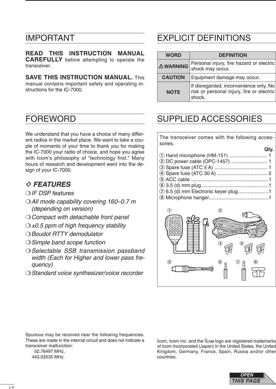
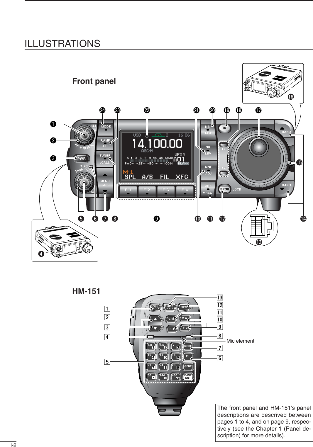
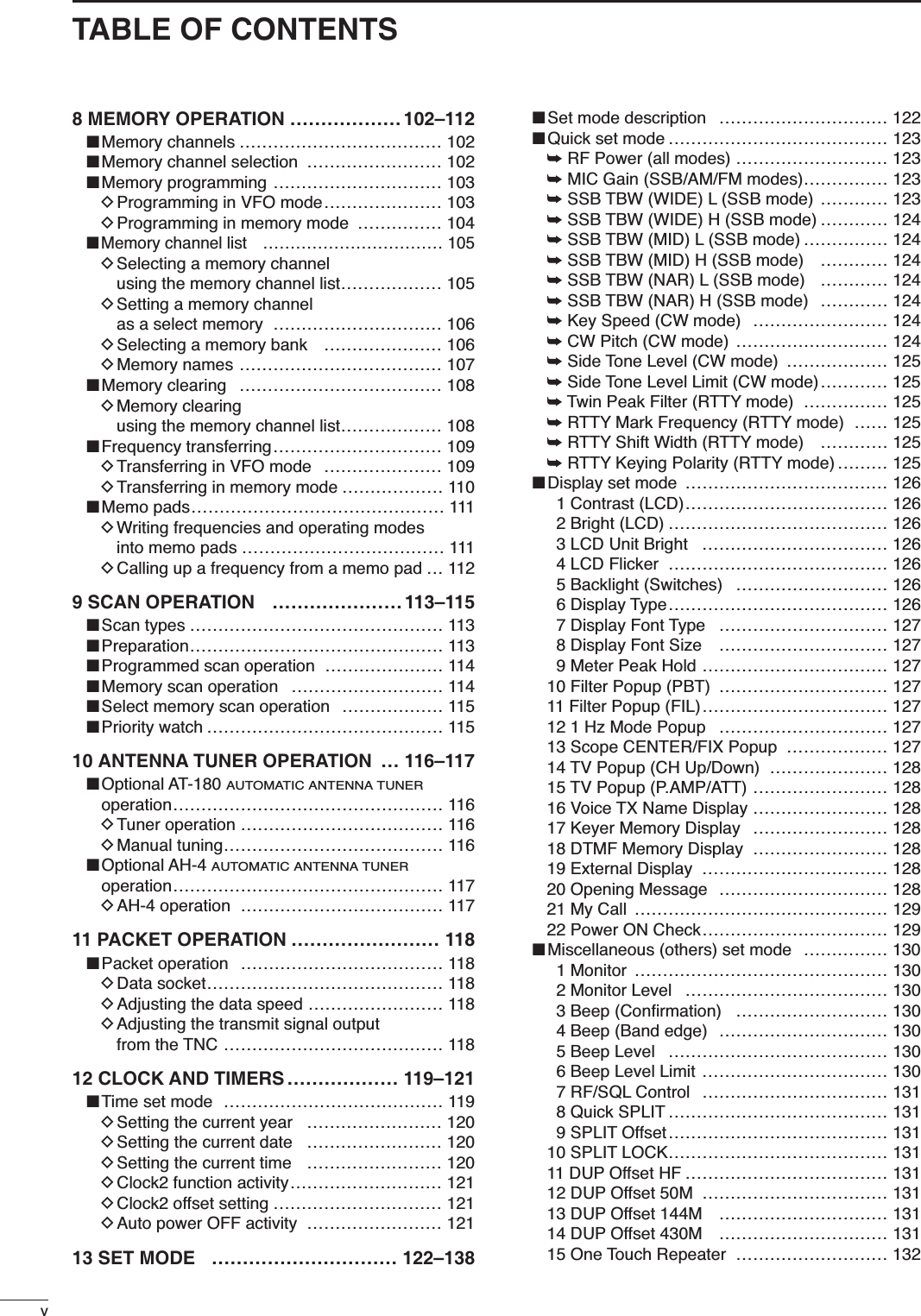
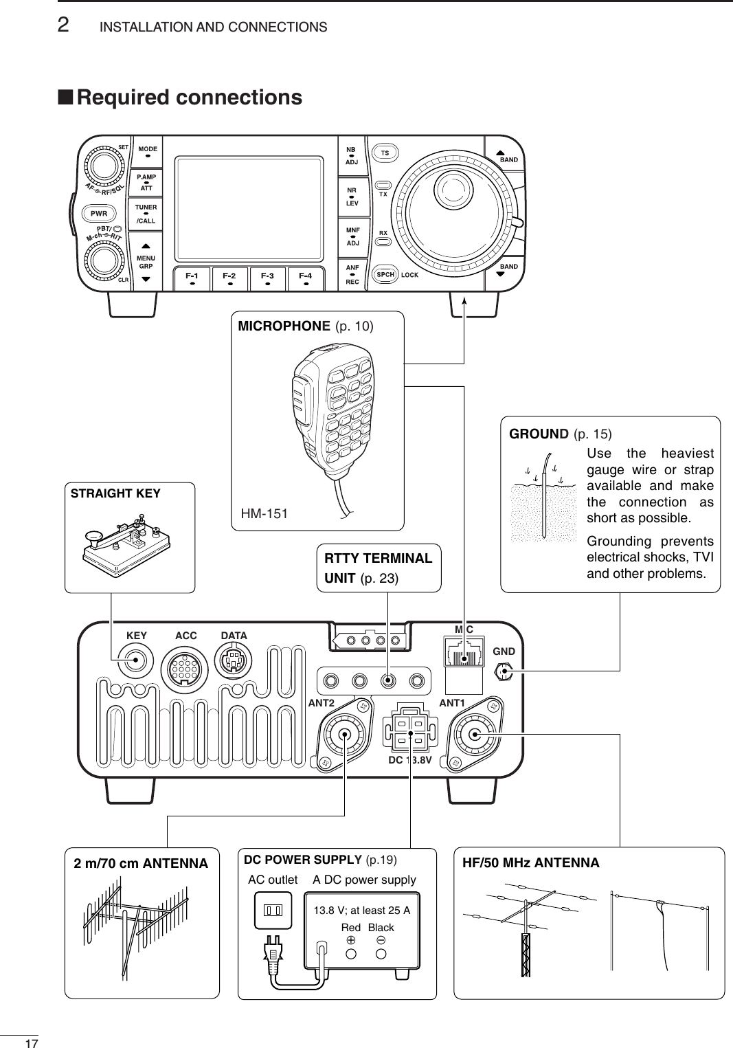
![i-3■Front panelqAF GAIN CONTROL [AF] (inner control; p. 33)wRF GAIN CONTROL/SQUELCH CONTROL[RF/SQL] (outer control; p. 35)ePOWER KEY [PWR] (p. 25)rFRONT PANEL LATCH (p. 16)tPASSBAND TUNING/M-ch/RIT CONTROLS[PBT/M-ch/RIT] (pgs. 75, 79, 88, 102, 106)yTWIN PBT (M-ch/RIT) INDICATOR (pgs. 75, 79, 88, 102, 106)uMENU/GROUP KEYS [MENU/GRP] (p. 153)iTUNER/CALL KEY [TUNER/CALL] (pgs. 102, 116)oMULTI-FUNCTION KEYS [F1]/[F2]/[F3]/[F4] (pgs. 5–8, 153)!0 MANUAL NOTCH KEY [MNF/ADJ] (p. 83)!1 AUTO NOTCH/VOICE RECORDER KEY[ANF/•REC] (pgs. 82, 95)!2 SPCH/LOCK KEY [SPCH/LOCK] (pgs. 34, 37)!3 MICROPHONE CONNECTOR (p. 10)!4UP/DOWN (BAND) KEYS[Y(BAND)]/[Z(BAND)]!5 MAIN DIAL TENSION LATCH!6 HEADPHONE JACK [PHONES] (p. 18)!7 MAIN DIAL [DIAL]!8 RECEIVE/TRANSMIT INDICATORS [RX]/[TX]!9 TUNING STEP KEY [TS] (pgs. 30–32)@0 NOISE BLANKER KEY [NB/ADJ] (p. 80)@1 NOISE REDUCTION KEY [NR/LEV] (p. 81)@2 FUNCTION DISPLAY (p. 13)@3 PRE AMP/ATTENUATOR KEY [P.AMP/ATT](p. 74)@4 MODE KEY [MODE] (p. 34)■Microphone (HM-151)zSPCH/LOCK KEY [SPCH/LOCK] (p. 34, 37)xPTT SWITCH [PTT] (p. 37)cUP/DOWN SWITCHES [Y]/[Z]vTRANSMIT INDICATORbKEYPAD (pgs. 28, 29)nFILTER SELECTION [FIL] (p. 77)mMODE KEY [MODE] (p. 34),POWER INDICATOR.PROGRAMMABLE FUNCTION KEYS [F-1]/[F-2]⁄0 MEMORY WRITE [MW] (pgs. 103, 104)⁄1 VFO/MEMORY SELECTION [V/M](pgs. 27, 102, 109)⁄2 TRANSMIT FREQUENCY CHECK [XFC] (pgs. 65, 91)⁄3 TUNER/CALL KEY [TUNER/CALL] (pgs. 102, 116)](https://usermanual.wiki/ICOM-orporated/242700/User-Guide-602836-Page-4.png)
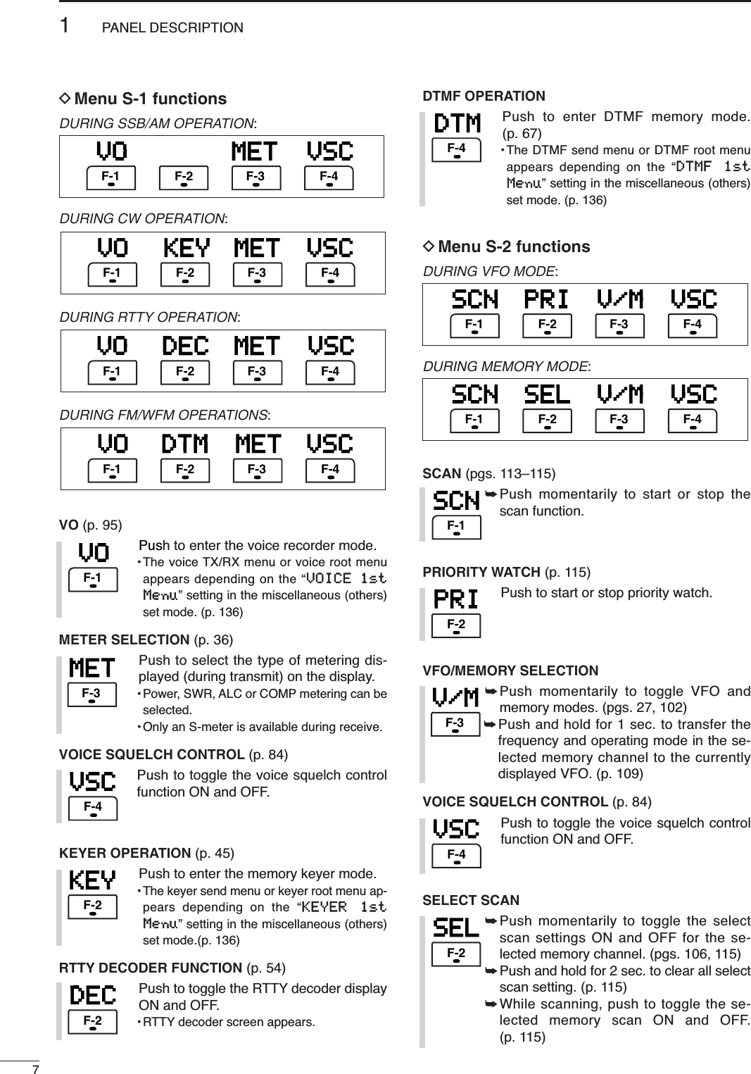
![iiRWARNING RF EXPOSURE! This device emitsRadio Frequency (RF) energy. Extreme caution should beobserved when operating this device. If you have anyquestions regarding RF exposure and safety standardsplease refer to the Federal Communications CommissionOffice of Engineering and Technology’s report on Evalu-ating Compliance with FCC Guidelines for Human RadioFrequency Electromagnetic Fields (OET Bulletin 65).RWARNING HIGH VOLTAGE! NEVER attach anantenna or internal antenna connector during transmis-sion. This may result in an electrical shock or burn.RNEVER apply AC to the [DC13.8V] socket on thetransceiver rear panel. This could cause a fire or damagethe transceiver.RNEVER apply more than 16 V DC, such as a 24 Vbattery, to the [DC13.8V] jack on the transceiver rearpanel. This could cause a fire or damage the transceiver.RNEVER let metal, wire or other objects touch any in-ternal part or connectors on the rear panel of the trans-ceiver. This may result in an electric shock.RNEVER connect or use the HM-151 (microphone)with other transceiver. This could cause damage to thetransceiver. The HM-151 is designed for use with the IC-7000 ONLYNEVER expose the transceiver to rain, snow or any liq-uids.AVOID using or placing the transceiver in areas with tem-peratures below –10°C (+14°F) or above +60°C (+140°F).Be aware that temperatures on a vehicle’s dashboard canexceed +80°C (+176°F), resulting in permanent damageto the transceiver if left there for extended periods.AVOID placing the transceiver in excessively dusty envi-ronments or in direct sunlight.AVOID placing the transceiver against walls or puttinganything on top of the transceiver. This will obstruct heatdissipation.Place unit in a secure place to avoid inadvertent use bychildren.During mobile operation, NEVER place the transceiverwhere air bag deployment may be obstructed.During mobile operation, DO NOT place the transceiverwhere hot or cold air blows directly onto it.During mobile operation, DO NOT operate the transceiverwithout running the vehicle’s engine. When the trans-ceiver’s power is ON and your vehicle’s engine is OFF,the vehicle’s battery will soon become exhausted.Make sure the transceiver power is OFF before startingthe vehicle. This will avoid possible damage to the trans-ceiver by ignition voltage spikes.During maritime mobile operation, keep the transceiverand microphone as far away as possible from the mag-netic navigation compass to prevent erroneous indica-tions.BE CAREFUL! The rear panel will become hot when op-erating the transceiver continuously for long periods.BE CAREFUL! If a linear amplifier is connected, set thetransceiver’s RF output power to less than the linear am-plifier’s maximum input level, otherwise, the linear ampli-fier will be damaged.Use Icom microphones only (supplied or optional). Othermanufacturer’s microphones have different pin assign-ments, and connection to the IC-7000 may damage thetransceiver.Beat signals may be heard on some frequencies.These will occur as a result of circuit construction.For U.S.A. onlyCaution: Changes or modifications to this transceiver,not expressly approved by Icom Inc., could void yourauthority to operate this transceiver under FCC regu-lations.PRECAUTIONS](https://usermanual.wiki/ICOM-orporated/242700/User-Guide-602836-Page-5.png)
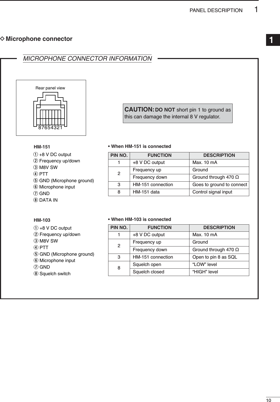
![iiiIMPORTANT …………………………………………i-1FOREWORD ………………………………………… i-1EXPLICIT DEFINITIONS …………………………… i-1SUPPLIED ACCESSORIES …………………………i-1ILLUSTRATIONS ……………………………………i-2■Front panel ……………………………………… i-3■Microphone (HM-151) ………………………… i-3PRECAUTIONS ………………………………………iiTABLE OF CONTENTS …………………………… iii1 PANEL DESCRIPTION ………………… 1–14■Front panel ………………………………………… 1■Multi-function keys ……………………………… 5DMenu M-1 functions …………………………… 5DMenu M-2 functions …………………………… 5DMenu M-3 functions …………………………… 5DMenu S-1 functions …………………………… 7DMenu S-2 functions …………………………… 7DMenu S-3 functions …………………………… 8DMenu G-1 (Scope) functions ………………… 8■Microphone (HM-151) …………………………… 9DMicrophone connector ……………………… 10■Rear panel ……………………………………… 11DDATA socket …………………………………… 12DACC socket …………………………………… 12■Function display ………………………………… 132INSTALLATION AND CONNECTIONS… 15–24■Unpacking ……………………………………… 15■Selecting a location……………………………… 15■Grounding………………………………………… 15■Antenna connection……………………………… 15■Installation ……………………………………… 16DSingle body mounting ………………………… 16DStand …………………………………………… 16DFront panel separation ……………………… 16DFront panel mounting ………………………… 16■Required connections…………………………… 17■Advanced connections ………………………… 18■Power supply connections……………………… 19■Connecting a DC power supply ……………… 19■Battery connections …………………………… 19■External antenna tuners………………………… 20■Linear amplifier connections …………………… 21■Connections for CW …………………………… 22■Connections for RTTY (FSK) ………………… 23DWhen connecting to [ACC] socket ………… 23DWhen connecting to [MIC] connector ……… 23■Connections for packet ………………………… 24DWhen connecting to [DATA] socket ………… 24DWhen connecting to [ACC] socket ………… 24DWhen connecting to [MIC] connector ……… 243 BASIC OPERATION ……………………25–38■When first applying power (CPU resetting)…… 25DMenu resetting (M-1) ………………………… 25■Initial settings …………………………………… 25■VFO description ………………………………… 26DDifferences between VFO and memory mode ………………………………… 26■VFO operation …………………………………… 27DSelecting VFO A/VFO B ……………………… 27DVFO equalization……………………………… 27■Selecting VFO/memory mode ………………… 27■Selecting an operating band …………………… 28DUsing the band stacking registers…………… 28■Frequency setting ……………………………… 29DTuning with the main dial …………………… 29DDirect frequency entry with the microphone’s keypad ……………… 29DProgrammable tuning step…………………… 30DSelecting “kHz” step ………………………… 30DSelecting 1 Hz or 10 Hz step (SSB/CW/RTTY only) ………………………… 31D1 MHz quick tuning step (FM/WFM/AM only) …………………………… 31D1⁄4tuning function (CW/RTTY only) ………… 32DAuto tuning step function …………………… 33DBand edge warning beep …………………… 33■Volume setting …………………………………… 33■Operating mode selection ……………………… 34■Voice synthesizer function ……………………… 34■Squelch and receive (RF) sensitivity ………… 35■Meter function …………………………………… 36DMulti-function meter…………………………… 36■Lock functions …………………………………… 37DDial lock function ……………………………… 37DMicrophone lock function …………………… 37■Basic transmit operation ……………………… 37DTransmitting …………………………………… 37DSetting output power ………………………… 38DSetting microphone gain……………………… 384 RECEIVE AND TRANSMIT …………… 39–71■Operating SSB…………………………………… 39DConvenient functions for receive …………… 39DConvenient functions for transmit …………… 40DAbout 5 MHz band operation (USA version only) …………………………… 40■Operating CW …………………………………… 41DConvenient functions for receive …………… 42DConvenient functions for transmit …………… 42DCW reverse mode …………………………… 43DCW side tone function………………………… 43DCW pitch control ……………………………… 44DElectronic CW keyer ………………………… 45DMemory keyer send menu …………………… 46DEditing a keyer memory ……………………… 47DContest number set mode …………………… 481 Number Style ……………………………… 482 Count UP Trigger …………………………… 483 Present Number …………………………… 48DKeyer set mode ……………………………… 491 Keyer Repeat Time ………………………… 492 Dot/Dash Ratio……………………………… 493 Rise Time …………………………………… 50TABLE OF CONTENTS](https://usermanual.wiki/ICOM-orporated/242700/User-Guide-602836-Page-6.png)
![iv4 Paddle Polarity ……………………………… 505 Keyer Type ………………………………… 506 MIC U/D Keyer (HM-103) ………………… 50DPaddle operation from [MIC] connector ………………………… 50■Operating RTTY (FSK) ………………………… 51DConvenient functions for receive …………… 52DRTTY reverse mode ………………………… 53DTwin peak filter………………………………… 53DFunctions for the RTTY decoder indication… 54DSetting the decoder threshold level ………… 54DRTTY decode set mode ……………………… 551 RTTY Decode USOS ……………………… 552 RTTY Decode New Line Code …………… 55DPre-setting for using RTTY terminal or TNC 56■Operating AM …………………………………… 57DConvenient functions for receive …………… 57DConvenient functions for transmit …………… 58■Operating FM …………………………………… 59DConvenient functions for receive …………… 59DConvenient functions for transmit …………… 59DTone squelch operation ……………………… 60DTone scan operation ………………………… 61DDTCS operation ……………………………… 62■Repeater operation ……………………………… 63DOne-touch repeater function ………………… 63DRepeater tone frequency …………………… 64DTransmit frequency monitor check ………… 65DAuto repeater function ……………………… 65DStoring a non standard repeater …………… 66■1750 Hz tone burst ……………………………… 67■DTMF memory encoder ………………………… 67DDTMF send menu …………………………… 67DProgramming a DTMF code ………………… 68DDTMF speed…………………………………… 68■TV channel operation …………………………… 69DConvenient functions for receive …………… 69DSkip channel setting ………………………… 70DChannel frequency adjustment ……………… 715 FUNCTIONS FOR RECEIVE…………… 72–84■Simple band scope ……………………………… 72DFix mode ……………………………………… 72DCenter mode…………………………………… 73DScope set mode ……………………………… 731 Max Hold …………………………………… 742 Scope Size ………………………………… 743 FAST Sweep………………………………… 744 FAST Sweep Sound ……………………… 74■Preamp and attenuator ………………………… 74■RIT function ……………………………………… 75■AGC function …………………………………… 76DAGC time constant selection ………………… 76DSetting the AGC time constant ……………… 76■IF filter selection ………………………………… 77DIF filter selection ……………………………… 77DFilter passband width setting (SSB/CW/RTTY/AM only) …………………… 78DIF filter shape (SSB/CW only) ……………… 78■Twin PBT operation …………………………… 79■Noise blanker …………………………………… 80DNoise blanker set mode ……………………… 801 NB Level …………………………………… 802 NB Width …………………………………… 80■Noise reduction ………………………………… 81DNoise reduction set mode …………………… 81➥NR Level …………………………………… 81■Notch function …………………………………… 82DAuto notch function …………………………… 82DManual notch function………………………… 83DManual notch filter set mode ………………… 83■Voice squelch control function ………………… 84■Meter peak hold function ……………………… 846FUNCTIONS FOR TRANSMIT………… 85–94■VOX function …………………………………… 85DAdjusting the VOX function ………………… 85DVOX set mode ………………………………… 861 VOX Gain …………………………………… 862 Anti-VOX …………………………………… 863 VOX Delay ………………………………… 86■Transmit filter width setting (SSB only) ……… 86■Break-in function ………………………………… 87DSemi break-in operation ……………………… 87DFull break-in operation ……………………… 87■∂TX function …………………………………… 88■Monitor function ………………………………… 89■Speech compressor …………………………… 89DCompression level setting …………………… 90➥COMP Level ……………………………… 90■Split frequency operation ……………………… 91■Quick split function ……………………………… 92DSplit offset frequency setting ………………… 93DQuick split setting …………………………… 93■Measuring SWR…………………………………… 94DSpot measurement …………………………… 94DPlot measurement …………………………… 947 VOICE RECORDER FUNCTIONS …… 95–101■Digital voice recorder …………………………… 95■Recording a received audio ……………………… 95DBasic recording ……………………………… 95DOne-touch voice recording…………………… 96■Playing the recorded contents …………………… 96■Erasing the recorded contents…………………… 97■Recording a message for transmit ……………… 98DRecording ……………………………………… 98DConfirming/Erasing the recorded message… 98■Programming a memory name for transmit …… 99■Sending a recorded message ………………… 100DTransmit level setting ……………………… 100■Voice set mode…………………………………… 101DVoice set mode ……………………………… 1011 Auto Monitor ……………………………… 1012 MIC Memo ………………………………… 101TABLE OF CONTENTS1234567891011121314151617181920](https://usermanual.wiki/ICOM-orporated/242700/User-Guide-602836-Page-7.png)
![vi16 Auto Repeater ……………………………… 13217 Tuner (Auto Start) ………………………… 13218 Tuner (PTT start) …………………………… 13319 [TUNER] Switch …………………………… 13320 VSEND Select ……………………………… 13321 SPEECH level ……………………………… 13322 SPEECH Language ……………………… 13323 SPEECH Speed …………………………… 13324 SPEECH S-Level ………………………… 13425 SPEECH [MODE] Switch ………………… 13426 Memopad Numbers ……………………… 13427 SCAN Speed ……………………………… 13428 SCAN Resume …………………………… 13429 MAIN DIAL Auto TS ……………………… 13430 HM-151 [F-1] ……………………………… 13531 HM-151 [F-2] ……………………………… 13532 MIC Up/Down Speed ……………………… 13533 Quick RIT/∂TX Clear ……………………… 13534 SSB/CW Synchronous Tuning …………… 13535 CW Normal Side …………………………… 13636 VOICE 1st Menu ………………………… 13637 KEYER 1st Menu ………………………… 13638 DTMF 1st Menu …………………………… 13639 Mode Select (SSB) ………………………… 13640 Mode Select (CW) ………………………… 13641 Mode Select (RTTY) ……………………… 13642 Mode Select (AM) ………………………… 13743 Mode Select (FM) ………………………… 13744 Mode Select (WFM) ……………………… 13745 External Keypad (VOICE) ………………… 13746 External Keypad (KEYER)………………… 13747 Front Keypad Type ………………………… 13848 CI-V Baud Rate …………………………… 13849 CI-V Address ……………………………… 13850 CI-V Transceive …………………………… 13851 REF Adjust ………………………………… 13814 MAINTENANCE ………………………… 139■Fuse replacement ……………………………… 139■Memory backup………………………………… 139■Cleaning ………………………………………… 13915 TROUBLESHOOTING …………… 140–14116 OPTIONAL UNITS SETTING ……… 142–143■MB-106CARRYING HANDLE…………………… 142■AT-180 internal switch description …………… 14317 CONTROL COMMAND …………… 144–148■Remote jack (CI-V) information ……………… 144DCI-V connection example …………………… 144DData format …………………………………… 144DCommand table ……………………………… 144DTo send/read memory contents …………… 148DBand stacking register ……………………… 148DCodes for memory keyer contents ………… 148DCharacter’s code for my call ……………… 149DCodes for memory name contents ………… 149DSplit/Duplex frequency setting……………… 149DRepeater tone/tone squelch frequency setting ………………………………………… 149DDTCS code and polarity setting…………… 14918 SPECIFICATIONS ………………………… 150■General ………………………………………… 150■Transmitter ……………………………………… 150■Receiver ………………………………………… 15019 OPTIONS …………………………… 151–15220 MENU GUIDE ……………………… 153–15421 ABOUT CE ………………………… 155–156TABLE OF CONTENTS1234567891011121314151617181920](https://usermanual.wiki/ICOM-orporated/242700/User-Guide-602836-Page-9.png)
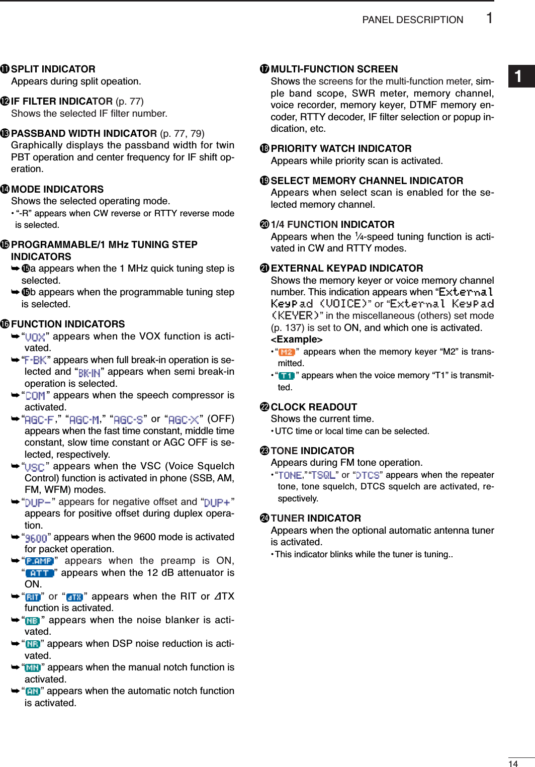
![qAF GAIN CONTROL [AF(SET)] (inner control; p. 33)➥Rotate to vary the audio output level from thespeaker or headphones.Push momentarily to enter the set mode menu.•Push again to exit the set mode menu.➥Push and hold for 1 sec. to toggle between thefrequency display mode or TV mode.wRF GAIN CONTROL/SQUELCH CONTROL[RF/SQL] (outer control; p. 35)Adjusts the RF gain and squelch threshold level.The squelch, when closed, mutes the speaker orheadphones when no signal is received, reducingnoise.•The squelch is particularly effective for FM and WFMmodes. It is also available in other modes.•12 to 1 o’clock position is recommended for any settingof the [RF/SQL] control.•The control can be set to ‘Auto’ (RF gain control in SSB,CW and RTTY; squelch control in AM, FM and WFM) orsquelch control (RF gain is fixed at maximum) in the mis-cellaneous (others) set mode as follows. (p. 131)• When functioning as RF gain/squelch control•When functioning as RF gain control(Squelch is fixed open; SSB, CW, RTTY only)•When functioning as squelch control(RF gain is fixed at maximum.)ePOWER KEY [PWR] (p. 25)➥While transceiver’s power is OFF, push to turn thepower ON.•Turn the DC power supply ON in advance.➥While transceiver’s power is ON, push and holdfor 1 sec. to turn the power OFF.rFRONT PANEL LATCH (p. 16)Pull away from the transceiver (towards yourselfwhen looking at the front of the transceiver) to de-tach the front panel from the main body of the trans-ceiver.tPASSBAND TUNING/M-ch/RIT CONTROLS[PBT/M-ch/RIT]➥Push inner control to toggle the twin PassbandTuning (PBT) or memory channel/RIT functionON and OFF.➥While Twin PBT is selected (p. 79):●●Adjusts the receiver’s DSP filter passbandwidth.•Passband width and shift frequency are displayedon the LCD.•The default variable range is half of the IF filterpassband width. 25 Hz step is available.●●Push and hold inner control for 1 sec. to returnthe PBT to default settings.Low cutHigh cut Center+–PBT1PBT2Squelch is open.S-metersquelchS-meter squelchthresholdNoise squelch threshold(FM/WFM modes)Lowest threshold Highest thresholdNoise squelch (FM/WFM modes)Minimum RF gainAdjustablerangeMaximum RF gainRecommended levelRF gain adjustablerangeMaximumRF gainS-meter shows squelch levelNoise squelch (WFM/FM modes)Squelch is open.MODESSB, CWRTTYAM, FMWFMAutoRF GAINSQLSQLSET MODE SELECTIONSQLSQLRF + SQLRF + SQLRF + SQLAudio oututdecreasesAudio outputincreases11PANEL DESCRIPTION■Front panel See the illustration of the Front panel on page i-2.](https://usermanual.wiki/ICOM-orporated/242700/User-Guide-602836-Page-10.png)
![✔What is the PBT control?PBT electronically narrows the IF passband width to rejectinterference. This transceiver uses DSP to implement PBT.➥While M-ch/RIT is selected:●●Rotate the inner control to select a memorychannel number (p. 102).●●Push inner control for 1 sec. to turn theRIT/∂TX mode ON (pgs. 75, 88).•Push [Z(MENU/GRP)] to exit the RIT/∂TX mode.●●While the RIT/∂TX mode is OFF:Rotates outer control to select a memory bank(p. 106).●●While the RIT/∂TX is ON:Rotate outer control to shift the receive ortransmit frequency (pgs. 75, 88).•“ ” or “ ” indicators appear when the RIT or∂TX function is activate, respectively.•The shift frequency range is ± 9.999 kHz in 1 Hzsteps (or ±9.99 kHz in 10 Hz steps).•When the RIT or ∂TX function is ON, push andhold [F-1 RIT]or [F-2 ∂TX]for 1 sec. to add orsubtract the frequency shift to the display fre-quency.✔What is the RIT function?RIT (Receiver Incremental Tuning) shifts the receive fre-quency without shifting the transmit frequency.This is useful for fine tuning for stations calling you off fre-quency or when you prefer to listen to slightly different-sounding voice characteristics, etc.✔What is the ∂TX function?The ∂TX shifts the transmit frequency without shifting the re-ceive frequency. This is useful for simple split frequency op-eration in CW, etc.yTWIN PBT (M-ch/RIT) INDICATOR (pgs. 75, 79, 88, 102)➥Indicates the status of [PBT/M-ch/RIT] (t) acti-vates as the Twin PBT function or memory chan-nel/RIT control.•Indicator is green when the Twin PBT is selected.•Indicator is off when the M-ch/RIT is selected.•Indicator is orange when the RIT or ∂TX function isactivate.uMENU/GROUP KEYS [MENU/GRP] (p. 153)➥Push either key one or more times to selectmenus within a menu group (M,Sor G(Graphic)).➥Push and hold for 1 sec. to select one of the threemenu groups: M-1to M-3,S-1to S-3and G-1(Scope) to G-3(SWR meter).iTUNER/CALL KEY [TUNER/CALL]➥During HF/50 MHz operation (p. 116):●●Push momentarily to toggle the automatic an-tenna tuner function ON and OFF.•An optional antenna tuner must be connected.• “ ” indicator appears when the tuner is ON.●●Push and hold for 2 sec. to manually tune theantenna.•An optional antenna tuner must be connected.• “ ” indicator appears when the tuner is ON.➥During 144/430 MHz operation (p. 102):Push momentarily to select the call channel (orreturn to the previous channel/frequency whenthe call channel is already selected).• “C1” is the 144 MHz call channel and “C2” is the 430MHz call channel.oMULTI-FUNCTION KEYS [F-1]/[F-2]/[F-3]/[F-4]➥Push to select the function indicated in the LCDdisplay above these keys. (pgs. 5–8, 153)•Functions vary depending on the active menu.Functions appearM-chRITM-ch RITFrequencydecreasesFrequencyincreasesChanneldecreasesChannelincreases21PANEL DESCRIPTION1See the illustration of the Front panel on page i-2.](https://usermanual.wiki/ICOM-orporated/242700/User-Guide-602836-Page-11.png)
![31PANEL DESCRIPTION!0 MANUAL NOTCH KEY [MNF/ADJ] (p. 83)➥Push momentarily to turn the manual notch func-tion ON and OFF in SSB, CW and AM modes.• “ ” appears on the display when the function is ac-tivated.➥Push and hold for 1 sec. to enter the manualnotch filter set mode.✔What is the notch function?The notch function is a narrow DSP filter that removes inter-fering tones from CW or AM signals while preserving the de-sired signal's frequency response. !1 AUTO NOTCH/VOICE RECORDER KEY[ANF/•REC]➥Push momentarily to turn the auto notch function(ANF) ON and OFF in SSB, AM, FM modes. (p. 82)• “ ” appears on the display when the function is ac-tivated.➥Push and hold for 1 sec. to record the receivedsignal’s audio. (p. 95)!2 SPCH/LOCK KEY [SPCH/LOCK]➥Push momentarily to have the frequency, etc. an-nounced by the speech synthesizer. (p. 34)•The parameters to be announced can be selected inthe miscellaneous (others) set mode. (p. 134)➥Push and hold for 1 sec. to toggle the dial lockfunction ON and OFF. (p. 37)•The dial lock function electronically locks the maindial.• “ ” appears while the dial lock function is activate.!3 MICROPHONE CONNECTOR (p. 10)Modular-type microphone connector—Accepts thesupplied microphone (HM-151).•The optional OPC-589 can be used to connect an 8-pinmicrophone such as the SM-20, if desired.•A microphone connector is also available on the rearpanel. DO NOT connect 2 microphones simultaneously.!4UP/DOWN (BAND) KEYS[Y(BAND)]/[Z(BAND)]➥Push momentarily to select a frequency band orTV channel.➥Push and hold [Y(BAND)]for 1 sec. to toggle thesimple band scope display ON and OFF.➥Push and hold [Z(BAND)]for 1 sec. to toggle themulti-function meter display ON and OFF.!5 MAIN DIAL TENSION LATCHSelects the main dial drag.•Three positions are available. Upper setting turns onclicks as the dial is turned..!6 HEADPHONE JACK [PHONES] (p. 18)Accepts headphones with 8–16 impedance.•When headphones are connected, no receive audiocomes from the speaker.•When the PHONES/SPEAKER switch on the back of thefront panel is set to the [SPEAKER] position, an externalspeaker can be used instead of headphones. This isconvenient for mobile or outdoor operation.!7 MAIN DIAL [DIAL]Changes the displayed frequency and selects val-ues for selected set mode items, etc.!8 RECEIVE/TRANSMIT INDICATORS [RX]/[TX]➥[RX]: Lights green in receive mode and whensquelch is open.➥[TX]: Lights red while transmitting.Back of the front panelSee the illustration of the Front panel on page i-2.](https://usermanual.wiki/ICOM-orporated/242700/User-Guide-602836-Page-12.png)
![41PANEL DESCRIPTION1!9 TUNING STEP KEY [TS] (pgs. 30–32)➥While in SSB/CW/RTTY modes, push momentar-ily to turn the programmable tuning step ON andOFF. While in AM/FM/WFM modes, push mo-mentarily to toggle the programmable tuning stepand 1 MHz quick tuning step.•While the programmable tuning step indicator is dis-played, the frequency can be changed in programmedkHz steps.•0.01 (AM/FM/WFM mode only), 0.1, 1, 5, 9, 10, 12.5,20, 25 and 100 kHz tuning steps are available.•A MHz quick tuning step is only available in AM, FMand WFM modes.➥While programmable tuning steps are OFF, turnsthe 1 Hz step ON and OFF when pushed andheld for 1 sec.•1 and 10 Hz steps are only available in SSB, CW andRTTY modes.•1 Hz indication appears, and the frequency can bechanged in 1 Hz steps.➥While the programmable tuning step is ON, en-ters the tuning step selection mode when pushedand held for 1 sec.@0 NOISE BLANKER KEY [NB/ADJ] (p. 80)➥Push momentarily to turn the noise blanker ONand OFF. The noise blanker reduces pulse-typenoise such as that generated by automobile igni-tion systems. This function does not work on non-pulse noise or in WFM mode.• “ ” appears when the noise blanker is ON.➥Push and hold for 1 sec. to enter the noiseblanker set mode.@1 NOISE REDUCTION KEY [NR/LEV] (p. 81)➥Push momentarily to turn DSP noise reductionON and OFF.• “ ” appears on the display when the function is ac-tivated.➥Push and hold for 1 sec. to enter the DSP noisereduction level.@2 FUNCTION DISPLAYShows the operating frequency, function key menus,simple band scope display, selected memory chan-nel, receiving TV channel, etc. See p. 13 for details.@3 PRE AMP/ATTENUATOR KEY [P.AMP/ATT](p. 74)➥Push momentarily to turn the preamp ON or OFF.•“ ” indicator appears when the preamp is acti-vated.➥Push and hold for 1 sec. to turn the 12 dB attenu-ator ON; push momentarily to turn the attenuatorOFF.• “ ” indicator appears when the attenuator is ac-tivated.✔What is the preamp?The preamp amplifies signals in the receiver front end (input)circuit to improve the S/N ratio and sensitivity. Turn ON‘P.AMP’ when receiving weak signals.✔What is the attenuator?The attenuator prevents a strong undesired signal near thedesired frequency or near your location, such as from abroadcast station, from causing distortion or spurious sig-nals.@4 MODE KEY [MODE] (p. 34)➥Push momentarily to cycle through the operatingmodes:USB/LSB ➧CW/CW-R ➧RTTY/RTTY-R ➧AM/FM/WFM➥Push and hold for 1 sec. to toggle the followingoperating modes:USB ↔LSBCW ↔CW-RRTTY ↔RTTY-RAM →FM →WFM →AM, etcOPERATING MODE SELECTIONPushmomentarilyPush and holdfor 1 sec.USB LSBAM FM WFMCW CW-RRTTY-RRTTYProgrammable tuning step indicatorSee the illustration of the Front panel on page i-2.](https://usermanual.wiki/ICOM-orporated/242700/User-Guide-602836-Page-13.png)
![51PANEL DESCRIPTION■Multi-function keysDMenu M-1 functionsSPLIT OPERATION➥Push momentarily to toggle the split func-tion ON and OFF. (p. 91)•“”and transmit frequency appear whenthe split function is ON.➥Push and hold for 1 sec. to turn the quicksplit function ON. (p. 92)•The offset frequency must be programmed inadvance using the miscellaneous (others) setmode. (p. 131)•The offset frequency is shifted from the dis-played frequency.•The quick split function can be turned OFF inthe miscellaneous (others) set mode. (p. 131)VFO A/B SELECTION➥Push momentarily to exchange the trans-mit VFO and receive VFO contents. (p.27)➥Push momentarily to toggle the transmis-sion VFO and reception VFO during splitoperation. (p. 91)➥Push momentarily to toggle the transmitand receive frequencies (and modes) ofmemory channels when the split functionis turned ON.➥Push and hold for 1 sec. to equalize thefrequency and operating mode of the twoVFO’s.•The lower indicated frequency and operatingmode are equalized to the upper (indicated)VFO frequency and operating mode.FILTER SELECTION (p. 77)➥Push momentarily to select one of threeIF filter settings.➥Push and hold for 1 sec. to enter the filterset mode.TRANSMIT FREQUENCY CHECK (pgs. 65, 91)Monitors the transmit frequency whenpushed and held.•While pushing this key, the transmit fre-quency can be changed with [DIAL].DMenu M-2 functionsMEMORY MENU (p. 105)Push momentarily to indicate the memoryfrequency and modes. •Memory list indication is available.MEMORY WRITE (pgs. 103, 104)Push and hold for 1 sec. to store the se-lected readout frequency and operatingmode into the displayed memory channel.MEMORY CLEAR (p. 108)Push and hold for 1 sec. to clear the se-lected memory channel contents.• “ ” appears.VFO/MEMORY SELECTION➥Push momentarily to toggle VFO andmemory modes. (pgs. 27, 102)➥Push and hold for 1 sec. to transfer theselected memory channel to the currentlydisplayed VFO. (p. 109)DMenu M-3 functionsDURING SSB OPERATION:DURING CW OPERATION:DURING RTTY OPERATION:DURING AM OPERATION:F-1 F-2 F-3 F-4VOX AGCF-1 F-2 F-3 F-41/4 AGCF-1 F-2 F-3 F-41/4BRK AGCF-1 F-2 F-3 F-4TBWVOX COM AGCF-4V/MF-3MCLF-2MWF-1MEMF-1 F-2 F-3 F-4MWMEM V/MMCLF-4XFCF-3FILF-2A/BF-1SPLSPL A/B FIL XFCF-1 F-2 F-3 F-4](https://usermanual.wiki/ICOM-orporated/242700/User-Guide-602836-Page-14.png)
![61PANEL DESCRIPTION1DURING FM/WFM OPERATIONS:VOX FUNCTION(p. 85)➥Push momentarily to toggle the VOX func-tion ON and OFF.•“ ” appears when the VOX function isON.➥Push and hold for 1 sec. to enter the VOXset mode.•The VOX gain, ANTI-VOX, VOX delay andVOX gain can be set in VOX set mode.✔What is the VOX function?The VOX function (voice operated transmission) activatesthe transmitter when you speak into the microphone; then,automatically returns to receive when you stop speaking.SPEECH COMPRESSOR (p. 89)➥Push momentarily to toggle the speechcompressor ON and OFF.•“ ” appears when the speech compres-sor is ON.➥Push and hold for 1 sec. to enter the com-pression level set mode.•Speech compression can be adjusted incompression level set mode.AGC(p. 76)➥Push to change the time constant of theAGC circuit.• “ ,” “ ” or “ ” appears whenthe fast time constant, middle time constantor slow time constant is selected, respec-tively.➥Push and hold for 1 sec. to enter the AGCset mode.• “ ” (OFF) can be selected.TBW (p. 86)➥Push momentarily to indicate the selectedTX filter width.• The popup indicator appears.➥Push and hold for 1 sec. to toggle the TXfilter width between narrow, middle orwide.•The following filters are specified as the de-fault. Each filter width can be set in the quickset mode. (pgs. 123, 124)WIDE : 100 Hz to 2900 HzMID : 300 Hz to 2700 HzNAR : 500 Hz to 2500 HzBREAK-IN FUNCTION (p. 87)➥Push momentarily to select semi-break-in,full break-in (QSK) and break-in OFF.•“ ” or “ ” appears when selectingsemi break-in or full break-in, respectively.•An external switch, such as a foot switch,must be connected to the ACC socket (pin 3,pin 7 or RTTY SEND—see p. 23) if break-inis turned OFF.➥Push and hold for 1 sec. to enter thebreak-in delay time set mode.✔What is the break-in function?Full break-in (QSK) activates the receiver between transmit-ted dots and dashes. This is useful when operating in nets,or during DX pile-ups and during contests, when “fast re-sponses” are common.1/4 FUNCTIONPush to toggle the 1/4-speed tuning func-tion ON and OFF in CW and RTTYmodes.•When the 1⁄4function is ON, “ ” appearsand fine tuning can be used.DUPLEX FUNCTION (p. 63)➥Push to select the duplex transmit offsetdirection or turn the function OFF.➥Push and hold for 1 sec. to turn the one-touch repeater function ON/OFF.FM TONE OPERATION➥Push momentarily to set the subaudibletone encoder for repeater use, tonesquelch function, DTCS and OFF.•“ ” appears when the repeater tonefunction is ON. (p. 63)• “ ” appears when the tone squelch func-tion is ON. (p. 60)•“ ” appears when the DTCS squelchfunction is ON. (p. 62)➥Push and hold for 1 sec. to enter the tonefrequency or DTCS code set mode. (pgs.60, 62)•Tone scan function is also available. (p. 61)➥Push and hold to transmit a 1750 Hz tonewhen pushing and holding [PTT]. (p. 67)9600 MODEPush to turn the 9600 bps data transmis-sion mode ON and OFF. (p. 118)F-49600F-3TONF-2DUPF-21/4F-1BRKF-4TBWF-3AGCF-2COMF-1VOXF-1 F-2 F-3 F-4VOX DUP TON9600](https://usermanual.wiki/ICOM-orporated/242700/User-Guide-602836-Page-15.png)
![81PANEL DESCRIPTION1DMenu S-3 functionsMEMORY WRITE (pgs. 103, 104)Push and hold for 1 sec. to store the dis-played VFO frequency and operatingmode into the selected memory channel.MEMO PAD WRITE (p. 111)Push to store the displayed VFO fre-quency and operating mode into a memopad.MEMO PAD READ(p. 112)Push to call up a memo pad.✔What is the memo pad function?The memo pad function stores the frequency and operatingmode for easy recall. The memo pads are separate from theusual memory channels. The default number of memo padsis 5, however, this can be increased to 10 in the miscella-neous (others) set mode, if desired. (p. 134)DMenu G-1 (Scope) functionsSWEEP STEPS (pgs. 72, 73)➥Push momentarily to change the sweepstep size.•Available steps are ±10, 25, 50, 100 and 250kHz.➥Push and hold for 1 sec. to change thesweep steps to ±10 kHz.PEAK HOLD (pgs. 72, 73)➥Push to freeze the current simple bandscope display.•“H” indicator appears while the function is inuse.➥Push and hold for 1 sec. to clear the peaklevels.•Peak levels are displayed in the backgroundon the simple band scope display. The peakhold function can be disabled in the scopeset mode. (p. 73)FIX/CENTER SELECTION (pgs. 72, 73)➥Push to toggle the simple band scope fixmode and center mode.•Fix mode:Rotating [DIAL] leaves the marker centered.•Center mode:Rotating [DIAL] moves the edge frequencies.➥While fix mode operation, push and holdfor 1 sec. to set the displayed frequencyto that of the marker.SWEEP SPEED➥Push momentarily to change the sweepspeed between Fast and Slow. (pgs. 72,73)➥Push and hold for 1 sec. to enter thescope set mode. (p. 73)F-4SPDF-3FIXF-2HLDF-1SPNF-1 F-2 F-3 F-4SPN HLD FIX SPDF-3MPRF-2MPWF-1MWF-1 F-2 F-3 F-4MW MPW MPR](https://usermanual.wiki/ICOM-orporated/242700/User-Guide-602836-Page-17.png)
![91PANEL DESCRIPTIONzSPCH/LOCK KEY [SPCH/LOCK]➥Push momentarily to have the frequency, etc. an-nounced by the speech synthesizer. (p. 34)•The parameters to be announced can be selected inthe miscellaneous (others) set mode. (p. 134)➥Push and hold for 1 sec. to toggle the microphonelock function ON and OFF. (p. 37)xPTT SWITCH [PTT] (p. 37)Push and hold to transmit; release to receive.cUP/DOWN SWITCHES [Y]/[Z]Change the operating frequency.•Push and hold to change the frequency repeatedly.•Tuning step size is 50 Hz if no TS indicator is displayed.vTRANSMIT INDICATORLights red while transmitting.bKEYPAD➥Pushing a key selects the operating band.•[(GENE)•] selects the general coverage band.➥Pushing the same key 2 or 3 times calls up otherstacked frequencies in the band. (p. 28)•Icom’s triple band stacking register memorizes 3 fre-quencies in each band.➥After pushing [(F-INP)ENT], enter a numeric fre-quency, followed by pressing [(F-INP)ENT]again. (p. 29)•e.g. to enter 14.195 MHz, push [(F-INP)ENT] [1] [4][•] [1] [9] [5] [(F-INP)ENT].nFILTER SELECTION [FIL] (p. 77)➥Push momentarily to select one of three IF filtersettings.➥Push and hold for 1 sec. to enter the filter setmode.mMODE KEY [MODE] (p. 34)➥Push momentarily to cycle through the operatingmodes:USB/LSB ➧CW/CW-R ➧RTTY/RTTY-R ➧AM/FM/WFM➥Push and hold for 1 sec. to toggle the followingoperating modes:USB ↔LSBCW ↔CW-RRTTY ↔RTTY-RAM →FM →WFM →AM, etc,POWER INDICATORLights green while transceiver power is ON..PROGRAMMABLE FUNCTION KEYS [F-1]/[F-2]Program and perform a selected function.•The functions can be assigned in the miscellaneous (oth-ers) set mode (p. 135). The default settings for [F-1] and[F-2] are “MPW” and “MPR,” respectively.⁄0 MEMORY WRITE [MW] (pgs. 103, 104)Push and hold for 1 sec. to store the displayed VFOfrequency and operating mode into the displayedmemory channel.⁄1 VFO/MEMORY SELECTION [V/M]➥Push momentarily to toggle VFO and memorymodes. (pgs. 27, 102)➥Push and hold for 1 sec. to transfer the selectedmemory channel to the currently displayed VFO.(p. 109)⁄2 TRANSMIT FREQUENCY CHECK [XFC] (pgs. 65, 91)Monitors the transmit frequency when pushed andheld.•While pushing this key, the transmit frequency can bechanged with [DIAL].⁄3 TUNER/CALL KEY [TUNER/CALL] ➥During HF/50 MHz operation (p. 116):●●Push momentarily to toggle the automatic an-tenna tuner function ON and OFF.•An optional antenna tuner must be connected.• “ ” indicator appears when the tuner is ON.●●Push and hold for 2 sec. to manually tune theantenna.•An optional antenna tuner must be connected.• “ ” indicator appears when the tuner is ON.➥During 144/430 MHz operation (p. 103):Push momentarily to select the call channel (orreturn to the previous channel/frequency whenthe call channel is already selected).• “C1” is the 144 MHz call channel and “C2” is the 430MHz call channel.■Microphone (HM-151)Default settings[F-1] (MPW): Push to store the selected readoutfrequency and operating mode intoa memo pad.[F-2] (MPR): Push to call up a memo pad.See the illustration of the HM-151 on page i-2.](https://usermanual.wiki/ICOM-orporated/242700/User-Guide-602836-Page-18.png)
![111PANEL DESCRIPTIONqELECTRONIC KEYER JACK [KEY] (p. 22)Accepts a paddle to activate the internal electronickeyer.•Selection between the internal electronic keyer andstraight key operation can be made in the keyer setmode. (p. 50)If you use an external electronic keyer, make surethe output voltage of the keyer is less than 0.4 Vwhen keying the transmitter.wACCESSORY SOCKET [ACC] (p. 12)Enables connection to external equipment such as aTNC for data communications, a linear amplifier oran automatic antenna selector/tuner, etc.•See page at right for socket wiring information.eDATA SOCKET [DATA] (p. 12)6-pin mini-DIN socket to connect a TNC (TerminalNode Controller), etc. for packet operation.•See page at right for socket wiring information.rVIDEO OUT JACK [VOUT] (p. 18)Outputs a video signal.tCI-V REMOTE CONTROL JACK [REMOTE](p. 144)➥Designed for use with a personal computer for re-mote control of the transceiver functions.➥Used for transceiver operation with another IcomCI-V transceiver or receiver.yTUNER CONTROL SOCKET [TUNER] (p. 20)Accepts the control cable from an optional AH-4HF/50MHzAUTOMATIC ANTENNA TUNER.uRTTY JACK [RTTY] (p. 23)Connects an external terminal unit for RTTY (FSK)operation.•The keying polarity, mark/shift frequencies and etc. canbe selected in quick set mode (p. 125).iEXTERNAL SPEAKER JACK [EXT SP] (p. 18)Accepts a 4–8 speaker.oMICROPHONE CONNECTOR [MIC] (p. 17)Accepts the supplied microphone (connected in par-allel with the front panel’s [MIC] connector).•See p. 2 for microphone notes.•See p. 10 for microphone connector information.!0 GROUND TERMINAL [GND] (p. 15)Connect this terminal to a station or vehicle groundto prevent electrical shocks, TVI, BCI and otherproblems.!1 ANTENNA CONNECTOR [ANT1], [ANT2] (p. 17)Accepts a 50 antenna with a PL-259 connector.•[ANT1] is for connection to an HF/50 MHz antenna.•[ANT2] is for connection to an 144/430 MHz antenna.•ANT1 is used below and ANT2 above 60 MHz.!2 DC POWER SOCKET [DC13.8V] (p. 19)Accepts 13.8 V DC through the supplied DC powercable.NOTE: DO NOT use a cigarette lighter socket as apower source when operating in a vehicle. The plugmay cause voltage drops and ignition noise may besuperimposed onto transmit or receive audio.Rear panel viewWhen connectinga straight keyWhen connectinga paddle(dot)(com)(dash)()KEY ACC DATA MICANT2 ANT1DC 13.8VGNDqwe yuirto!0!1!2■Rear panel](https://usermanual.wiki/ICOM-orporated/242700/User-Guide-602836-Page-20.png)
![121PANEL DESCRIPTION1ACCPIN No.NAME DESCRIPTION SPECIFICATIONS12348765910 11 1213Rear panel viewqbrown igraywred owhiteeorange !0 blackryellow !1 pinktgreen !2 lightblueyblueupurple !3 lightgreen1 8 V Regulated 8 V output. Output voltage : 8 V ±0.3 VOutput current : Less than 10 mA2 GND Connects to ground. ———Input/output pin. (HF/50 MHz only) Ground level : –0.5 V to 0.8 V3HSENDGoes to ground when transmitting. Output current : Less than 20 mAGrounded when transmits. Input current (Tx) : Less than 200 mA4 BDT Data line for the optional AT-180. ———5 BAND Band voltage output. Output voltage : 0 to 8.0 V(Varies with amateur band)6 ALC ALC voltage input. Control voltage : –4 V to 0 VInput impedance : More than 10 kInput/output pin. (144/430 MHz only) Ground level : –0.5 V to 0.8 V7VSENDGoes to ground when transmitting. Output current : Less than 20 mAGrounded when transmits. Input current (Tx) : Less than 200 mA8 13.8 V 13.8 V output when power is ON. Output current : Max. 1 A9 TKEY Key line for the optional AT-180. ———“High” level : More than 2.4 V10 FSKK Controls RTTY keying “Low” level : Less than 0.6 VOutput current : Less than 2 mA11 MOD Modulator input. Input impedance : 10 kInput level : Approx. 100 mV rmsAF detector output. Output impedance : 4.7 k12 AF Fixed level, regardless of [AF] Output level : 100–300 mV rmsposition indefault settings.13 SQLS Squelch output. SQL open : Less than 0.3 V/5 mAGrounded when squelch opens. SQL closed : More than 6.0 V/100 µADATAPIN No.NAME DESCRIPTION123456Rear panel view1 DATA IN Input terminal for data transmit. (1200 bps: AFSK/9600 bps: G3RUH, GMSK)2 GND Common ground for DATA IN, DATA OUT and AF OUT.3 PTT P PTT terminal for packet operation. Connect to ground to activate the transmitter.When grounded, microphone input (pin 6) of [MIC] connector will be disconnected.4 DATA OUT Data out terminal for 9600 bps operation only.5 AF OUT Data out terminal for 1200 bps operation only.Squelch out terminal. Becomes ground level when the transceiver receives a signalwhich opens the squelch.6SQL •To avoid interfering transmissions, connect squelch to the TNC to inhibit transmissionwhen squelch is open.• Keep RF gain at a normal level, otherwise a “SQL”signal will not be output.Color refers to the cable strands of the supplied cable.DDATA socketDACC socket](https://usermanual.wiki/ICOM-orporated/242700/User-Guide-602836-Page-21.png)
![131PANEL DESCRIPTIONqFREQUENCY READOUTShows the operating frequency.wMETER READOUTS➥Shows received signal strength while receiving.➥Shows either transmit power meter (Po), SWR,ALC or compression level meter (COM) whiletransmitting.eMULTI-FUNCTION KEY GUIDEIndicates the function of the multi-function keys.These alphanumeric readouts show a variety of in-formation such as current functions of the “F” keys[F-1] to [F-4].rSPLIT FREQUENCY READOUTShows the transmit frequency during split operation.tBLANK MEMORY INDICATORAppears when the displayed memory channel is notprogrammed (blank channel).• This indicator appears both in VFO and memory modes.yMEMORY CHANNEL READOUTShows the selected memory channel or scan edgechannel.•Memory bank indicator (A to E) appears to the left ofmemory channel.• This indicator appears both in VFO and memory modes.uVFO/MEMORY INDICATORS➥VFO A or B appears when VFO mode is selected;MEMO appears when memory mode is selected.iVOICE RECODER INDICATORSREC appears when the digital voice recoder func-tion is activated.oLOCK INDICATORAppears when the dial lock function is activated.!0 DIRECT FREQUENCY ENTRY INDICATOR (p. 29)Appears when the transceiver is ready for direct fre-quency entry.•This indicator appears when [(F-INP)ENT] key on theHM-151 is pushed.!0!2 !1 @4 @2!5aotuy!9@0!5b!8!3!4 @3ri@1ewq!6!7■Function displayACC 1 ACC 2q FSKK t AFw GND y SQLSe HSEND u 13.8 Vr MOD i ALCq 8 V t ALCw GND y VSENDe HSEND u 13.8 Vr BAND123488765910 11 121312347651234765Connect to ACC socket• When connecting the ACC conversion cable (OPC-599)](https://usermanual.wiki/ICOM-orporated/242700/User-Guide-602836-Page-22.png)
![215INSTALLATION AND CONNECTIONS■UnpackingAfter unpacking, immediately report any damage to thedelivering carrier or dealer. Keep the shipping cartons.For a description and a diagram of accessory equip-ment included with the IC-7000, see ‘Supplied acces-sories’ on p. i-1 of this manual.■Selecting a locationSelect a location for the transceiver that allows ade-quate air circulation, free from extreme heat, cold, orvibrations, and away from TV sets, TV antenna ele-ments, radios and other electromagnetic sources.The base of the transceiver has an adjustable standfor desktop use. Set the stand to one of two angles de-pending on your operating conditions. (see descriptionon right hand page)■GroundingTo prevent electrical shock, television interference(TVI), broadcast interference (BCI) and other prob-lems, ground the transceiver through the GROUNDterminal on the rear panel.For best results, connect a heavy gauge wire or strapto a long, buried copper rod. Make the distance be-tween the [GND] terminal and ground as short as pos-sible.RWARNING: NEVER connect the [GND] ter-minal to a gas pipe or electric conduit, since theconnection could cause an explosion or electricshock.■Antenna connectionFor radio communications the antenna is of critical im-portance for output power and sensitivity. Use well-matched 50-ohm antennas and coaxial feedline. AnSWR (standing wave radio) of 1.5:1 or lower is recom-mended when transmitting.CAUTION: Protect your transceiver from lightningby using a lightning arrestor.ANTENNA SWREach antenna is tuned for a specified frequencyrange and SWR increases outside that range. Whenthe SWR is higher than approx. 2.0 : 1, the trans-ceiver’s power drops to protect the final transistors.In this case, an antenna tuner is used to match thetransceiver and antenna. Low SWR allows full powerfor transmitting even when using the antenna tuner.The IC-7000 has an SWR meter to monitor the an-tenna SWR continuously.30 mm10 mm (soft solder)10 mm1–2 mmsolder solderSoftsolderCoupling ringPL-259 CONNECTOR INSTALLATION EXAMPLEqerwSlide the coupling ring down. Strip the cable jacket and soft solder.Slide the connector body on and solder it.Screw the coupling ring onto the connector body.Strip the cable as shown at left. Soft solder the center con-ductor.](https://usermanual.wiki/ICOM-orporated/242700/User-Guide-602836-Page-24.png)
![2216INSTALLATION AND CONNECTIONS■InstallationDSingle body mounting DStand*CAUTION: Non-supplied screws (longer than 8 mm)may damage the internal units.MB-62(optional)Supplied withthe MB-62*NutSpring washerFlat washerPull backthen upDFront panel separationDFront panel mountingqWhile pulling the front panel latch towards you,slide the front panel to the left (fig. 1).wAttach the optional OPC-1443 to the main bodyand tighten the supplied screw as in fig. 2.eAttach the other end of the OPC-1443 to the de-tached front panel as in fig. 3.CAUTION: NEVER detach/attach the front panelwhen connecting the DC power supply (or battery).Be sure to disconnect the DC power cable from the[13.8 V] socket on the transceiver rear panel.qAttach the MB-105 to a flat surface using the foursupplied screws (fig. 1).wFix the detached front panel to the MB-105 as il-lustrated in fig. 2.BE CAREFUL to mount the MB-105 so that thefront panel attaches with the correct side up.Separation cable(OPC-1443)Separation cable(OPC-1443)To removefig. 1 fig. 2 fig. 3Latchfig. 1fig. 2To raise the stand:With the transceiver upside down, pull the stand to-wards the rear panel and then upwards, as illus-trated below.](https://usermanual.wiki/ICOM-orporated/242700/User-Guide-602836-Page-25.png)
![182INSTALLATION AND CONNECTIONS2■Advanced connectionsKEY ACC DATA MICANT2 ANT1DC 13.8VGNDOPC-589 (p. 152)DESKTOP (p. 151)MICROPHONESPEAKERACC SOCKET(p. 12)DATA SOCKET (p. 12)VIDEO OUTAH-4 (p. 20) AH-2bEXTERNALSPEAKER (p. 151)HEADPHONESSP-7/SP-10SM-20orREMOTE(p. 144)Used for computer control and transceive operation.Selectable with the [PHONE/SPEAKER]switch on the back of the front panel.6-pin mini DIN socket to connect to a TNC, etc. for packet operation.to [VOUT] jack3.5(d) mmGNDVout](https://usermanual.wiki/ICOM-orporated/242700/User-Guide-602836-Page-27.png)
![192INSTALLATION AND CONNECTIONS■Power supply connectionsUse the DC power supply with a 25 A capacity whenoperating the transceiver with AC power. Refer to thediagrams below.CAUTION: Before connecting the DC powercable, check the following important items. Makesure:•The [POWER] switch is OFF.•Output voltage of the power source is 12–15 V.• DC power cable polarity is correct.Red : positive +terminalBlack : negative _terminalA DC power supplyAC outletAC cable30 A fuses SuppliedDC power cable13.8 V; at least 25 ABlack_Red+TransceiverDC powersocket■Battery connections•RWARNING NEVER connect to a batterywithout supplying a DC fuse, otherwise a firehazard occurs.•NEVER connect the transceiver directly to a 24 Vbattery.•DO NOT use the cigarette lighter socket for powerconnections. (See p. 11 for details)•Attach a rubber grommet when passing the DCpower cable through a metal plate to prevent ashort circuit.IMPORTANT!Detailed installation notes for Icom mobile trans-ceivers to be fitted into vehicles are available. Con-tact your Icom dealer or distributor.GrommetCONNECTING A VEHICLE BATTERYNote: Use terminals forthe cable connections.CrimpSolderSuppliedDC power cableredblack12 Vbattery■Connecting a DC power supply](https://usermanual.wiki/ICOM-orporated/242700/User-Guide-602836-Page-28.png)
![202INSTALLATION AND CONNECTIONS2■External antenna tunersGroundGroundLong wire or optional AH-2bAH-4ANT1IC-7000Coaxial cable(from the AH-4)CONNECTING THE AH-4CONNECTING THE AT-180•Turn the IC-7000’s power OFF when connectingthe AT-180, otherwise, the CPU may malfunctionand the AT-180 may not function properly.•The OPC-742 is required when using both the AT-180 and a 2m/70cm linear amplifier.• Do not connect [ANT2] to the AT-180. When usingan HF to 2m/70cm dual or wide-band antenna,use a duplexer between the AT-180 and antennasince 2 m/70 cm signals do not pass through theAT-180.[ANT 1]TransceiverDuplexerHF to 2 m/70 cmantennaAT-180[ANT 2]IC-7000Ground GroundAT-180HFto 6 mantenna[TRANSCEIVER][ANT][ANT1][ACC] [ACC]ACC cable supplied with the AT-180Coaxial cable suppliedwith the AT-180Either of the two external connectors](https://usermanual.wiki/ICOM-orporated/242700/User-Guide-602836-Page-29.png)
![212INSTALLATION AND CONNECTIONS■Linear amplifier connections Use the [ANT1] connector when connecting an HF/50MHz linear amplifier.CONNECTING THE IC-PW1/EUROTo anantenna ACC-1ANTANT1ACCINPUT1REMOTEEXCITER11&2GNDGNDIC-PW1/EUROAC outlet Non-European versions : 100–120/220–240 V European version : 230 VGroundTransceiverREMOTERemote control cable (supplied with the IC-PW1/EURO)ACC cable (supplied with the IC-PW1/EURO)Coaxial cable(supplied with the IC-PW1/EURO)7-pin sideOPC-599 conversion cable()CONNECTING A NON-ICOM LINEAR AMPLIFIERRWARNING:•Set the transceiver output power and linear ampli-fier ALC output level referring to the linear ampli-fier instruction manual. Be sure the linear ampli-fier keying circuit control voltage is compatiblewith the IC-7000, before connecting to HSENDline (ACC cable).•The ALC input level must be in the range 0 V to–4 V, and the transceiver does not accept positivevoltage. Non-matched ALC and RF power settingscould cause a fire or damage the linear amplifier.•The IC-7000 SEND relay is rated at 16 V and a0.5 A DC. If these levels are exceeded, a largerexternal relay must be used.HSEND(Orange)ALC (Blue)13.8V (Gray)GroundGNDRelayRF INRF OUTALCKEYANT1ACC cableACCTransceiver50 1 coaxial cableTo a nantenna](https://usermanual.wiki/ICOM-orporated/242700/User-Guide-602836-Page-30.png)
![222INSTALLATION AND CONNECTIONS2Rear panelPaddle[KEY][MICROPHONE]Straight keyMicrophone (HM-103)Keyer set mode settingKeyer set mode (p. 49)4812[ACC]123765910 1113For no break-in operation:Connect an external switch such as a foot switch; or use the RTTY SEND terminal for all bands. (See p. 23)See p. 50 for connection details: Paddle operation from [MIC] connector.NormalReverseBugPaddle polarity NormalMIC U/D keyer (HM-103) ONKeyer Type ELEC-KEYPaddle polarity NormalKeyer Type StraightPaddle polarity NormalKeyer Type ELEC-KEYPaddle polarity ReverseKeyer Type ELEC-KEYPaddle polarity NormalKeyer Type BUG-KEY■Connections for CW](https://usermanual.wiki/ICOM-orporated/242700/User-Guide-602836-Page-31.png)
![232INSTALLATION AND CONNECTIONS[ACC]Rear panel4812123765910 1113[RTTY] [EXT SP]TU or TNC Personal computerRear panel viewColors refer to connectionto the supplied ACC cable.*1Connect SQL line when required.eHF/50 MHz: orangeu144/430 MHz: purple*2SQL*1 (light green)FSKK (black)AF out (light blue)MSEND*2GND (red)GNDGNDAF3-conductor 1/8˝ plug (supplied)2-conductor 1/8˝ plugFSKKSENDDWhen connecting to [ACC] socketDWhen connecting to [MIC] connector[MIC][ACC]Rear paneli SQL!2 AF out (light blue)r PTTt GND y MICu GNDRear panel view TU or TNC Personal computer4812123765910 1113Rear panel view■Connections for RTTY (FSK)](https://usermanual.wiki/ICOM-orporated/242700/User-Guide-602836-Page-32.png)
![242INSTALLATION AND CONNECTIONS2■Connections for packetDWhen connecting to [DATA] socketDWhen connecting to [MIC] connectorDWhen connecting to [ACC] socket[MIC][ACC]Rear paneli SQL!2 AF out (light blue)r PTTt GND y MICu GNDRear panel view TU or TNC Personal computer4812123765910 1113Rear panel view[DATA] (Rear panel)Personal computerTU or TNC RS-232CPTTPTTPDATA INSQLRX AUDIOGNDTX AUDIOqweytrAF OUTDATA OUTGNDSQL[ACC]Rear panel4812123765910 1113Rear panel viewColors refer to connectionto the supplied ACC cable.*1Connect SQL line when required.SQL*1 (light green)AF in (pink)AF out (light blue)MSEND (orange)GND (red)TU or TNC Personal computer](https://usermanual.wiki/ICOM-orporated/242700/User-Guide-602836-Page-33.png)
![325BASIC OPERATION■When first applying power (CPU resetting)Before first applying power, make sure all connec-tions required for your system are complete by refer-ring to Chapter 2. Then, reset the transceiver usingthe following procedure.Resetting CLEARS all programmed contents inmemory channels and returns programmed valuesin set mode.qMake sure the transceiver power is OFF.wWhile pushing [Y(BAND)] and [Z(BAND)], push[PWR] for 1 sec. to start resetting.• The internal CPU is reset.•The display changes to ‘ALL CLEAR,’ ‘RF power 100%’and ‘Initial frequency and Mode’ as shown at right.The transceiver’s initial frequency and mode[PWR][Y][Z][RF/SQL]: Center[LOCK]: OFF[POWER]: OFF[AF]: Max. CCW[PBT]: Center(Push and hold for 1 sec.)[PBT/M-ch/RIT]: PBT(indicator lights)CCW : counterclockwiseDMenu resetting (M-1)Turn power ON, then check the display. If any of thefollowing indicators appear, turn them OFF as follows:•Tuning step indicators, Z, (SSB, CW or RTTY):Push [TS].•MHz tuning step indicator, Z, (FM, WFM or AM):Push [TS]• 1 Hz frequency readout (SSB, CW or RTTY):Push and hold [TS].• Preamp indicator, :Push [P.AMP/ATT]• Attenuator indicator, :Push [P.AMP/ATT]• Noise blanker indicator, :Push [NB/ADJ]• Noise reduction indicator, :Push [NR/LEV]• Manual notch indicator, :Push [MNF/ADJ]• Auto notch indicator, :Push [ANF/•REC]• Memory mode indicator, MEMO:Use [F-4 V/M]in the M-2menu (p. 27).• Split indicator, :Use [F-1 SPL]in the M-1menu (p. 91).If you can’t figure out how to return to the menu M-1:While pushing either [Y(MENU/GRP)] or [Z(MENU/GRP)], turn power ON.•The other groups are also reset to S-1or G-1(Scope) inthis time.[PWR][MENU/GRP]After resetting the transceiver, set controls andswitches as shown in the diagram below.■Initial settings](https://usermanual.wiki/ICOM-orporated/242700/User-Guide-602836-Page-34.png)
![DDifferences between VFO and memory modeVFO MODEEach VFO shows a frequency and operating mode. Ifthe frequency or operating mode is changed, the VFOautomatically memorizes the new frequency or oper-ating mode.When VFO settings are changed with frequency andmode from another VFO or memory mode, the last-used frequency and operating mode for that VFO ap-pear.[EXAMPLE]MEMORYMODE(pgs. 102–110)Each memory channel shows a frequency and oper-ating mode like a VFO. Even if the frequency or modeis changed, the memory channel does not memorizethe new frequency or operating mode.When a memory channel is changed with frquencyand mode from another memory channel or VFOmode, the memorized frequency and operating modeappear.[EXAMPLE]263BASIC OPERATION3VFO is an abbreviation of Variable Frequency Oscilla-tor, and traditionally refers to an oscillator. The IC-7000 VFO is somewhat different. The VFO dis-play of the IC-7000 acts like a computer’s window andcan show one frequency and one operating mode.You can call up a desired frequency to the VFO withthe memo pad-read key (p. 112) or the memory trans-fer function (p. 109). You can also change the fre-quency with [DIAL] and select an operating mode with[MODE] key or call up previously accessed frequencyand modes with the band stacking register (p. 28).The IC-7000 has two VFOs, specially suited for splitfrequency operation. The VFOs are called VFO A andVFO B. You can use the desired VFO to call up a fre-quency and operating mode for operation.VFOMODEKEYSelectMEMORYCHANNELDIALMEMO PAD28.025 MHz7.001 MHz21.295 MHzBANDChangeTransferTransfer TransferChanged frequency (14.123 MHz) does not appear and memorized frequency (14.100 MHz) appears instead.Memory channel 1 isselected.The frequency is changed.Memory channel 1 isselected again.Another memory channelis selected.VFO is selected.The frequency is changed.VFO is selected again.Changed frequency (14.123 MHz) appears.Memory mode is selected.■VFO description](https://usermanual.wiki/ICOM-orporated/242700/User-Guide-602836-Page-35.png)
![■Selecting VFO/memory mode273BASIC OPERATIONqSelect M-1.wPush [F-2 A/B]to toggle VFO A or VFO B.[MENU/GRP] [F-2]Either “ ” or “ ” appears.DSelecting VFO A/VFO BqSelect M-1.wPush [F-2 A/B]for 1 sec. to set the undisplayedVFO frequency and mode to those of the displayedVFO.•Three beeps sound when the VFO equalization is com-pleted.CONVENIENTUse two VFOs as a quick memoryWhen you find a new station, but you wish to continuesearching, the Two VFO system can be used for quickmemory storage.qPush [F-2 A/B]for 1 sec. to store the displayed fre-quency into the undisplayed VFO.wContinue searching for stations.ePush [F-2 A/B]to retrieve the stored frequency.rTo continue searching for a station, push [F-2 A/B]again.Pushthen push again.for 1 sec.,DVFO equalization■VFO operationqSelect M-2.wPush [F-4 V/M]to toggle VFO and memorymodes.“VFO” indicatorMemory channelindicator[MENU/GRP] [F-4]Menu group selectionPush [MENU/GRP] for 1 sec. Selection from: M,SorG(Graphic)Menu selection (Example: M)Push [MENU/GRP] momentarily. Selection from: M-1,M-2orM-3EitherY or ZEitherY or Z](https://usermanual.wiki/ICOM-orporated/242700/User-Guide-602836-Page-36.png)
![283BASIC OPERATION3The triple band stacking register provides 3 memoriesin one band. 3 sets of frequency and operating modeon each band are automatically stored when used.If a band key (on the HM-151) is pushed once, the lastused frequency and operating mode are called up.When the key is pushed again, another stored fre-quency and operating mode are called up.This function is convenient when you operate 3 oper-ating modes on one band. For example, one registeris used for a CW frequency, another for an SSB fre-quency and the other one for an RTTY frequency.See the table below for a list of the bands availableand the default settings for each band.SPCH /LOCKTUNER /CALL XFCV/MF-1 F-2FILMODEGENEMW123456789.0CEF-INPENT1.8 3.5 710 14 1821 24 2850 144 430Band keysHM-151■Selecting an operating bandBAND REGISTER 1 REGISTER 2 REGISTER 31.8 MHz 1.900000 MHz CW 1.910000 MHz CW 1.915000 MHz CW3.5 MHz 3.550000 MHz LSB 3.560000 MHz LSB 3.580000 MHz LSB7 MHz 7.050000 MHz LSB 7.060000 MHz LSB 7.020000 MHz CW10 MHz 10.120000 MHz CW 10.130000 MHz CW 10.140000 MHz CW14 MHz 14.100000 MHz USB 14.200000 MHz USB 14.050000 MHz CW18 MHz 18.100000 MHz USB 18.130000 MHz USB 18.150000 MHz USB21 MHz 21.200000 MHz USB 21.300000 MHz USB 21.050000 MHz CW24 MHz 24.950000 MHz USB 24.980000 MHz USB 24.900000 MHz CW28 MHz 28.500000 MHz USB 29.500000 MHz USB 28.100000 MHz CW50 MHz 50.100000 MHz USB 50.200000 MHz USB 51.000000 MHz FM144 MHz 145.000000 MHz FM 145.100000 MHz FM 145.200000 MHz FM430 MHz 433.000000 MHz FM 433.100000 MHz FM 433.200000 MHz FMGeneral 15.000000 MHz USB 15.100000 MHz USB 15.200000 MHz USBqPush [(14)5], then select a frequency and an oper-ating mode.•Frequency and operating mode are memorized in thefirst band stacking register.wPush [(14)5] again, then select another frequencyand operating mode.•This frequency and operating mode are memorized inthe second band stacking register.ePush [(14)5] again, then select another frequencyand operating mode.•This frequency and operating mode are memorized inthe third band stacking register.•When a fourth frequency and operating mode are se-lected on a band, the first register set in step q, is overwritten.SPCH /LOCKTUNER /CALL XFCV/MF-1 F-2FILMODEGENEMW123456789.0CEF-INPENT1.8 3.5 710 14 1821 24 2850 144 430FILMODEGENE123456789.0CEF-INPENT1.8 3.5 710 14 1821 24 2850 144 430[Example]: 14 MHz bandHM-151DUsing the band stacking registers](https://usermanual.wiki/ICOM-orporated/242700/User-Guide-602836-Page-37.png)
![293BASIC OPERATIONThe transceiver has several tuning methods for conve-nient frequency tuning.■Frequency settingDTuning with the main dialqPush [Y(BAND)] or [Z(BAND)] to select the desiredband. Or push the desired band key on the micro-phone 1–3 times.•Three different frequencies can be selected on eachband with the microphone’s band key. (See previouspage “Using the band stacking register.”)wRotate [DIAL] to set the desired frequency.If the dial lock function is activated, “ ” indicatorlights, and [DIAL] does not function. In this case,push [SPCH/LOCK] to deactivate the lock func-tion. (p. 37)SPCH /LOCKTUNER /CALL XFCV/MF-1 F-2FILMODEGENEMW123456789.0CEF-INPENT1.8 3.5 710 14 1821 24 2850 144 430Band keysHM-151[Y][Z][DIAL]DDirect frequency entry with the microphone’s keypadThe HM-151 has a keypad for direct frequency entryas described right.qPush [F-INP/ENT].• “ ” appears.wInput the desired frequency.•Push [(50)•] to input “ • (decimal point)” between theMHz digits and kHz digits.ePush [F-INP/ENT] to set the input frequency.•To cancel the input, push [CE] instead of [F-INP/ENT].[EXAMPLES]F-INPENTF-INPENTF-INPENTF-INPENTF-INPENTF-INPENTF-INPENTF-INPENTF-INPENTF-INPENTF-INPENT11.811.811.823.523.523.5410410514514514F-INPENT514618721721721824.50.50.50.50.50014401440144014421.280 21.24514.025 MHz18.0725 MHz706 kHz5.100 MHz7.000 MHzSPCH /LOCKTUNER /CALL XFCV/MF-1 F-2FILMODEGENEMW123456789.0CEF-INPENT1.8 3.5 710 14 1821 24 2850 144 430 KeypadHM-151](https://usermanual.wiki/ICOM-orporated/242700/User-Guide-602836-Page-38.png)
![303BASIC OPERATION3DProgrammable tuning stepThe operating frequency can be changed in steps of(0.01 (AM/FM/WFM only), 0.1, 1, 5, 9, 10, 12.5, 20 25or 100 kHz selectable) for quick tuning.qPush [TS] momentarily to turn the programmabletuning function ON.•“Z” appears when the programmable tuning function isON.wRotate [DIAL] to change the frequency in pro-grammed kHz steps.ePush [TS] again to turn the programmable tuningfunction OFF.•“Z” disappears.rRotate [DIAL] for normal tuning, if desired.Programmable tuning step indicator[TS] [DIAL]AppearsDSelecting “kHz” stepProgrammable tuning steps are available to suit youroperating requirements.These tuning steps are:• Independently selectable for each mode•Selectable from 0.01 (AM/FM/WFM only), 0.1, 1, 5,9, 10, 12.5, 20, 25 and 100 kHzqPush [TS] momentarily to turn the programmabletuning step ON.•“Z” appears when the programmable tuning function isON.wPush [TS] for 1 sec. to enter the tuning step set-ting display.•The tuning step setting for the selected mode appears.eSelect the desired operating mode with [MODE].(see p. 34)rRotate [DIAL] to select the desired tuning stepfrom 0.01 (FM/WFM/AM only), 0.1, 1, 5, 9, 10,12.5, 20, 25 or 100 kHz.•Push [F-4 DEF]for 1 sec. to return to the default set-ting, if desired.tRepeat steps eand rto select the “kHz” tuningsteps for other modes, if desired.yPush [TS] (or [Z(MENU/GRP)]) to exit the settingdisplay.Appears[TS][MODE] [DIAL]](https://usermanual.wiki/ICOM-orporated/242700/User-Guide-602836-Page-39.png)
![313BASIC OPERATIONWhen neither the quick tuning step or programmabletuning step “Z” appear, rotating [DIAL] changes thefrequency in increments of 1 or 10 Hz. These tuningsteps are only available in SSB, CW and RTTYmodes.qSelect SSB, CW or RTTY mode if necessary.wPush and hold [TS] for 1 sec. to toggle betweenthe 1 Hz and 10 Hz step settings.•When the 1 Hz step is selected, the 1 Hz digit appearsin the frequency indication; when the 10 Hz step is se-lected, the 1 Hz digit disappears from the frequency in-dication.•Rotating [DIAL] changes the frequency in 1 Hz or 10Hztuning step.Push and holdfor 1 sec.Rotating [DIAL] changes the frequency in 1 Hz steps.Rotating [DIAL] changes the frequency in 10 Hz steps.[TS][MODE] [DIAL]DSelecting 1 Hz or 10 Hz step (SSB/CW/RTTY only)The quick tuning step function allows you to changethe frequency in 1 MHz steps when rotating [DIAL].This function is only available in FM, WFM and AMmodes.qSelect FM, WFM or AM mode if necessary.wPush [TS] momentarily to toggle between the 1MHz tuning step and the programmable tuningstep.•“Z” appears above the 1 MHz indicator when the 1MHz tuning step is selected.•Rotating [DIAL] changes the frequency 1 MHz.Quick tuning step indicatorRotating [DIAL] changes the frequency in 1 MHz steps.[TS][MODE] [DIAL]AppearsD1 MHz quick tuning step (FM/WFM/AM only)](https://usermanual.wiki/ICOM-orporated/242700/User-Guide-602836-Page-40.png)
![323BASIC OPERATION3• [TS] switch flow chartSSB/CW/RTTY modes Any mode FM/WFM/AM modes1 Hz tuning10 Hz tuning momentarily momentarily 1 MHz tuningProgrammable step tuning(100 Hz –100 kHz)momentarilyPushPushPush Push1 sec.1 sec.1 sec.Selectable for each mode.Appears AppearsAppearsD1⁄4tuning function (CW/RTTY only)While operating in CW/RTTY, the 1⁄4tuning function isavailable for critical tuning. Dial sensitivity is reducedto 1⁄4of normal when the 1⁄4function is in use.qSelect M-3.wPush [F-2 1/4]to toggle the 1⁄4function ON andOFF.• “ ” indication appears when the function is inuse.[MENU/GRP] [F-2]Appears•Push and hold [MENU/GRP] for 1 sec. once or twiceto select the menu group M.•Push [MENU/GRP] momentarily one or more times toselect the menu M-3.](https://usermanual.wiki/ICOM-orporated/242700/User-Guide-602836-Page-41.png)
![333BASIC OPERATION■Volume settingRotate [AF] control clockwise to increase; counter-clockwise to decrease the audio output level.• Set a suitable audio level.[AF]Audio oututdecreasesAudio outputincreasesDBand edge warning beepWhen selecting a frequency that lies outside of aband’s specified frequency range, a warning beepsounds.This function can be turned OFF in set mode, if de-sired.qEnter the miscellaneous (others) set mode asabove.wPush [F-1 ≤]or [F-2 ≥]to select “Beep (BandEdge),” then rotate [DIAL] to select the desiredsetting.•Push [F-4 DEF]for 1 sec. to return to default setting.ePush [Z(MENU/GRP)] twice to return the normal op-erating mode.DAuto tuning step functionWhen rotating the tuning dial rapidly, the tuning speedaccelerates automatically as selected.qPush [AF(SET)] momentarily to enter the set modemenu.wPush [F-4 OTH]to enter the miscellaneous (oth-ers) set mode.ePush [F-1 ≤]or [F-2 ≥]to select “MAIN DIALAuto TS.”rRotate [DIAL] to select the desired tuning speedfrom high, low and OFF.•HIGH: Approx. 5 times faster•LOW : Approx. twice faster•OFF : Auto tuning step is turned OFF•Push [F-4 DEF]for 1 sec. to return to default setting.tPush [Z(MENU/GRP)] twice to return to the normaloperating mode.[DIAL][MENU/GRP][AF][F-1] [F-2] [F-4]](https://usermanual.wiki/ICOM-orporated/242700/User-Guide-602836-Page-42.png)
![343BASIC OPERATION3■Operating mode selectionThe following modes are available in the IC-7000:SSB (LSB/USB), CW, CW-R (CW reverse), RTTY,RTTY-R (RTTY reverse), AM, FM and WFM (receiveonly).To select the desired mode of operation, push[MODE] one or more times, then push [MODE] for1 sec., if necessary. See the diagram at right for theorder of selection.• The selected mode is indicated in the function display.NOTE:If a desired mode cannot be selected, itmay be hidden because of a setting in the miscel-laneous (others) set mode (p. 136).SPCH /LOCKTUNER /CALL XFCV/MF-1 F-2FILMODEGENEMW123456789.0CEF-INPENT1.8 3.5 710 14 1821 24 2850 144 430HM-151MODEOPERATING MODE SELECTIONPushmomentarilyPush and holdfor 1 sec.USB LSBAM FM WFMCW CW-RRTTY-RRTTY[MODE]■Voice synthesizer functionThe IC-7000 has a voice synthesizer function. Thisfunction announces the S-meter level, operating fre-quency and mode (S-meter level’s announcementcan be deactivated—p. 134) in a clear, electronicallygenerated voice, in English (or Japanese).qSelect the desired parameters to be announced,such as Audio level, speed, language, contents, inthe miscellaneous (others) set mode. (p. 134)wPush [SPCH/LOCK] momentarily to announce theselected contents.•Push [SPCH/LOCK] momentarily to stop the an-nouncement.[SPCH/LOCK]](https://usermanual.wiki/ICOM-orporated/242700/User-Guide-602836-Page-43.png)
![353BASIC OPERATION■Squelch and receive (RF) sensitivityAdjusts the RF gain and squelch threshold level. Thesquelch removes noise output from the speaker(closed position) when no signal is received. • The squelch is particularly effective for FM. It is also avail-able for other modes.•The 12 to 1 o’clock position is recommended for any set-ting of the [RF/SQL] control.•The control can be set as ‘Auto’ (RF gain control in SSB,CW and RTTY; squelch control in AM, FM and WFM (RFgain is fixed at maximum) in the miscellaneous (others)set mode as follows (p. 131).Adjusting RF gain (Receive sensitivity)Normally, [RF/SQL] is set to the 11 o’clock position.Rotate [RF/SQL] to the 11 o’clock position for maxi-mum sensitivity. • Rotating counterclockwise from the maximum position re-duces sensitivity.• The S-meter indicates receive sensitivity.Adjusting squelch (Removing non-signal noise)Rotate [RF/SQL] clockwise when receiving no signal,until the noise just disappears.•[RX] indicator light goes out.• Rotating [RF/SQL] past the threshold point invokes the S-meter squelch—this allows you to set a minimum signallevel needed to open the squelch.• When setting as RF gain/squelch control•When functioning as RF gain control (Squelch is fixed open; SSB, CW, RTTY only)•When functioning as squelch control (RF gain isfixed at maximum)While rotating the RF gain control, noise may beheard. This comes from the DSP unit and does notindicate an equipment malfunction.Squelch is open.S-metersquelchS-meter squelchthresholdNoise squelch threshold(FM/WFM mode)Lowest threshold Highest thresholdNoise squelch (FM/WFM mode)Minimum RF gainAdjustablerangeMaximum RF gainRecommended levelRF gain adjustablerangeMaximumRF gainS-meter showssquelch levelNoise squelch (FM/WFM mode)Squelch is open.[RF/SQL]SETTING OPERATIONRF+SQLCan be used in all modes.(default)Functions as noise squelch or S-metersquelch in AM, FM and WFM modes;S-meter squelch only in other modes.SQL Operates as a squelch control.• RF gain is fixed at maximum sensitivity.Operates as an RF gain control inSSB, CW and RTTY modes.AUTO •Squelch is fixed open.Operates as a squelch control in AM,FM and WFM modes.• RF gain is fixed at maximum sensitivity.](https://usermanual.wiki/ICOM-orporated/242700/User-Guide-602836-Page-44.png)
![DMulti-function meter363BASIC OPERATION3■Meter functionThe transceiver has 4 transmit meter functions foryour convenience. Select the desired meter with the[F-3 MET]in the S-1display.qSelect S-1.wPush [F-3 MET]one or more times to select fromRF power (Po), SWR, ALC or compression level(COM).•The display indication changes as the table at the right.•Push and hold [MENU/GRP] for 1 sec. once or twiceto select the menu group S.•Push [MENU/GRP] momentarily one or more times toselect the menu S-1.[MENU/GRP] [F-3]DISPLAY MEASUREMENTINDICATIONPoIndicates the relative RF output power in %.SWR Indicates the SWR on the transmissionline.ALCIndicates the ALC level. When the metermovement shows the input signal level ex-ceeds the allowable level, the ALC limitsthe RF power. In such cases, reduce theMIC gain setting (see p. 38) in the quickset mode.COM Indicates the compression level when thespeech compressor is in use.In addition, the transceiver can display the multi-func-tion meter in the graphic display, which displays alltransmit meters simultaneously.➥Select G-2(Multi-meter).The multi-function meter displays the internal tem-perature meter for your reference.•Push and hold [MENU/GRP] for 1 sec. once or twiceto select the menu group G.•Push [MENU/GRP] momentarily one or more times toselect the menu G-2(Multi-meter).[MENU/GRP]Quick entry➥Push [Z(BAND)] for 1 sec. to turn the multi-function meter ON and OFF.•Push [Z(MENU/GRP)] also to turn OFF.[Z]](https://usermanual.wiki/ICOM-orporated/242700/User-Guide-602836-Page-45.png)
![■Basic transmit operationDTransmitting373BASIC OPERATIONqPush [PTT] (microphone) to transmit.•[TX] indicator lights red.wRelease [PTT] (microphone) to return to receive.[TX] indicatorSPCH /LOCKTUNER /CALL XFCV/MF-1 F-2FILMODEGENEMW123456789.0CEF-INPENT1.8 3.5 710 14 1821 24 2850 144 430[PTT][TX]HM-151Before transmitting, monitor your selected op-erating frequency to make sure transmittingwon’t cause interference to other stations onthe same frequency. It’s good Amateur practiceto listen first, and then, even if nothing is heard,ask “is the frequency in use” once or twice, be-fore you begin operating on that frequency.DMicrophone lock functionThis function locks microphone keypads.➥Push [SPCH/LOCK] (microphone) for 1 sec. totoggle the microphone lock function ON and OFF.• “MIC LOCK ON” and “MIC LOCK OFF,” popup indica-tors appear, respectively•[PTT] and [SPCH/LOCK] can be used.• All keys on the transceiver can be used.SPCH /LOCKTUNER /CALL XFCV/MF-1 F-2FILMODEGENEMW123456789.0CEF-INPENT1.8 3.5 710 14 1821 24 2850 144 430HM-151SPCH /LOCK■Lock functionsThe dial lock function prevents accidental changecaused by [DIAL].➥Push [SPCH/LOCK] for 1 sec. to turn the dial lockfunction ON and OFF.•“ ” indicator appears while the dial lock function isactivated.[SPCH/LOCK]AppearsDDial lock functionThe lock function can only be activated when display-ing frequency, not in set mode, memory channel list-ing, or TV display.](https://usermanual.wiki/ICOM-orporated/242700/User-Guide-602836-Page-46.png)
![383BASIC OPERATION3qPush [AF(SET)] momentarily to enter the set modemenu.wPush [F-1 QS]to enter the quick set mode.ePush [F-1 Y]or [F-2 Z]to select “RF Power.”rRotate [DIAL] to set the desired output setting.•Output power is displayed in 1% steps (0% to 100%).tPush [Z(MENU/GRP)] to exit quick set mode.•Available power*Carrier power[MENU/GRP] [F-2][F-1] [DIAL][AF]DSetting output powerMicrophone gain must be adjusted properly so thatyour signal does not distort when transmitted.qSelect SSB or another phone mode (AM or FMmode).wSelect S-1.ePush [F-3 MET]one or more times to select theALC meter.•“ALC” appears.rPush [AF(SET)] momentarily to enter the set modemenu.tPush [F-1 QS]to enter the quick set mode.yPush [F-1 Y]or [F-2 Z]to select “MIC Gain.”uPush [PTT] (microphone) to transmit.•Speak into the microphone at your normal voice level.iWhile speaking into the microphone, rotate [DIAL]so that the ALC meter reading does not go outsidethe ALC zone.• Microphone gain is adjusted in 1% steps (0% to 100%).oRelease [PTT] (microphone) to return to receive.!0 Push [Z(MENU/GRP)] to exit the quick set mode.•Push [Z(MENU/GRP)] again to return the normal oper-ating mode.ALC zoneALC[MENU/GRP] [F-3][F-1] [F-2] [DIAL][AF]•Push and hold [MENU/GRP] for 1 sec. once or twiceto select the menu group S.•Push [MENU/GRP] momentarily one or more times toselect the menu S-1.DSetting microphone gainBAND SSB/CW AM*RTTY/FMHF 2–100 W 1–40 W50 MHz 2-100 W 1–40 W144 MHz 2–50 W 2–20 W430 MHz 2–35 W 2–14 WIf a linear amplifier is connected such as the IC-PW1/EURO,set the output power using the ALC meter (see below) to theALC zone (ALC meter reading should be within this zone),otherwise the linear amplifier will not work properly.](https://usermanual.wiki/ICOM-orporated/242700/User-Guide-602836-Page-47.png)
![DConvenient functions for receive439RECEIVE AND TRANSMIT■Operating SSBqPush [Y(BAND)]/[Z(BAND)] to select the desiredband or push a band key on the HM-151.wPush [MODE] momentarily or push and hold for 1 sec. to select LSB or USB mode.•Below 10 MHz LSB is automatically selected; above10 MHz USB is automatically selected.eRotate [DIAL] to tune in a desired signal.•The S-meter indicates received signal strength whensignal is received.rRotate [AF] to set audio to a comfortable listeninglevel.tPush [PTT] (microphone) to transmit.•[TX] indicator lights red.ySpeak into the microphone at your normal voicelevel.• Adjust ‘MIC Gain’ at this step, if necessary. (p. 38)uRelease [PTT] (microphone) to return to receive.“LSB” or “USB” appears[Y][Z][DIAL][MODE][AF] [TX] indicator• Preamp and attenuator (p. 74)➥Push [P.AMP/ATT] momentarily to tune the pre-amp ON or OFF.• “ ” appears when the preamp is set to ON.➥Push [P.AMP/ATT] for 1 sec. to turn the attenua-tor ON.•Push [P.AMP/ATT] momentarily to turn the attenuatorOFF.• “ ” appears when the attenuator is set to ON.• Twin PBT (passband tuning) (p. 79)➥Push [PBT/M-ch/RIT] (switch) momentarily onceor twice to select the twin PBT ON or OFF (M-chRIT).•PBT indicator lights green when the twin PBT is se-lected.➥Rotate [PBT/M-ch/RIT] (controls–inner/outer).•Push [PBT/M-ch/RIT(CLR)] to clear the settings.• AGC (auto gain control) (p. 76)➥While “M-3” is selected, push [F-3 AGC]momen-tarily one or more times to select AGC fast, AGCmiddle and AGC slow.•“ ,” “ ” and “ ” appears when thefast time constant, middle time constant and slowtime constant is selected, respectively.➥While “M-3” is selected, push [F-3 AGC]for 1sec. to enter the AGC set mode.•Push [F-2 FAST],[F-3 MID]or [F-4 SLOW]to selectthe time constant, then rotate [DIAL] to adjust the timeconstant.• Noise blanker (p. 80)➥Push [NB/ADJ] to turn the noise blanker ON andOFF.• “ ” appears when the noise blanker is set to ON.➥Push [NB/ADJ] for 1 sec. to enter the noiseblanker set mode, then rotate [DIAL] to adjust thethreshold level, or noise pulse width.• DSP noise reduction (p. 81)➥Push [NR/LEV] to turn the DSP noise reductionON and OFF.• “ ” appears when the DSP noise reduction is ON.➥Push [NR/LEV] for 1 sec. to enter the DSP noisereduction level set mode, then rotate [DIAL] toadjust the DSP noise reduction level.• Manual notch filter (pgs. 82, 83)➥Push [MNF/ADJ] to turn the manual notch filterON and OFF.• “ ” appears when the manual notch filter is set to ON.➥Push [MNF/ADJ] for 1 sec. to enter the manualnotch filter set mode.•Push [F-2 NF1],[F-3 NF2]to select the notch filter,push [F-4 NW]to set the filter width, rotate [DIAL] toset the notch frequency.• Auto notch filter (p. 82)➥Push [ANF/•REC] to turn the auto notch filter ONand OFF.• “ ” appears when the auto notch filter is set to ON.• VSC (voice squelch control) (p. 84)➥While “S-1” is selected, push [F-4 VSC]to turnthe VSC function ON and OFF.•“”appears when VSC function is set to ON.•Push and hold [MENU/GRP] for 1 sec. once or twiceto select the menu group M.•Push [MENU/GRP] momentarily one or more timesto select the menu M-3.](https://usermanual.wiki/ICOM-orporated/242700/User-Guide-602836-Page-48.png)
![404RECEIVE AND TRANSMIT4DConvenient functions for transmit• Transmit quality monitor (p. 89)➥Push [AF(SET)], then [F-4 OTH]to enter the mis-cellaneous (others) set mode. Select an item with[F-1 ≤]/[F-2 ≥], then rotate [DIAL] to turn themonitor function ON and OFF.• VOX (voice operated transmit) (p. 85)➥While “M-3” is selected, push [F-1 VOX]to turnthe VOX function ON and OFF.• “ ” appears when the VOX function is set to ON.➥While “M-3” is selected, push [F-1 VOX]for 1sec. to enter the VOX set mode.•Push [F-1 ≤]/[F-2 ≥]to select an item.•Rotate [DIAL] to set the value/conditions.• Speech compressor (p. 89)➥While “M-3” is selected, push [F-2 COM]to turnthe speech compressor ON and OFF.•“”appears when the speech compressor is set toON.➥While “M-3” is selected, push [F-2 COM]for 1sec. to enter the compression level set mode.•Rotate [DIAL] to adjust the compression level.•Push and hold [MENU/GRP] for 1 sec. once or twiceto select the menu group M.•Push [MENU/GRP] momentarily one or more timesto select the menu M-3.DAbout 5 MHz band operation (USA version only)Operation on the 5 MHz band is allowed on 5 discretefrequencies and must adhere to the following:• USB mode• Maximum of 50 watts ERP (Effective Radiated Power)• 2.8 kHz bandwidthIt is the operator’s responsibility to set all controls sothat the transmission in this band meets the stringentconditions under which we may use these frequencies.NOTE: We recommend that you store these fre-quencies, mode and filter settings into the memorychannel for easy recall.*The channel center frequencies that are specifiedby the FCC, show the center frequency of theirpassband. However, the IC-7000 displays carrierpoint frequency, so set 1.5 kHz below from FCCchannel center frequency.IC-7000 Tuning FCC ChannelFrequency* Center Frequency*5.33050 MHz 5.33200 MHz5.34650 MHz 5.34800 MHz5.36650 MHz 5.36800 MHz5.37150 MHz 5.37300 MHz5.40350 MHz 5.40500 MHzTo assist you in operating the 5 MHz band correctlywithin the rules specified by the FCC, transmissionis impossible on any 5 MHz band frequency otherthan the 5 frequencies indicated in the table above.](https://usermanual.wiki/ICOM-orporated/242700/User-Guide-602836-Page-49.png)
![414RECEIVE AND TRANSMIT■Operating CWqConnect a paddle or straight key as on page 22.wPush [Y(BAND)]/[Z(BAND)] to select the desiredband or push a band key on the HM-151.ePush [MODE] momentarily to select CW mode.•After CW mode is selected, push [MODE] for 1 sec. totoggle between CW and CW-R modes.rRotate [DIAL] to tune in a desired signal with thedesired tone frequency.tRotate [AF] to set audio to a comfortable listeninglevel.ySet CW break-in operation as semi break-in, fullbreak-in or OFF.•Push [F-1 BRK]one or more times to select the CWbreak-in operation.•“,” “,” and “OFF (no indication)” appears.➧BK-IN: semi break-in➧F-BK : full break-in➧OFF : no break-in (ACC socket connection is neces-sary as shown on page 22.)uSet the CW delay time when semi break-in opera-tion is selected.•Push [F-1 BRK]for 1 sec. to enter the break-in delaytime set mode.•Rotate [DIAL] to set the desired delay time.iSet CW setting in the keyer set mode (S-1).•Push [F-2 KEY],[Z(MENU/GRP)], then [F-4 SET]toenter the keyer set mode. (p. 49)oKeying to transmit, use the electric keyer or paddleto send your CW signals.•[TX] indicator lights red.• The Po meter indicates transmitted CW signal strength.!0 Stop keying to return to receive.Delay time of 7.5 dots is selected for semi break-in operation.Semi break-in operation is selected.Appears“CW” or “CW-R” appears[Y][Z][DIAL][MODE][AF] [TX] indicator[MENU/GRP] [F-4][F-1] [F-2]•Push and hold [MENU/GRP] for 1 sec. once or twiceto select the menu group S.•Push [MENU/GRP] momentarily one or more times toselect the menu S-1.•Push and hold [MENU/GRP] for 1 sec. once or twiceto select the menu group M.•Push [MENU/GRP] momentarily one or more times toselect the menu M-3.](https://usermanual.wiki/ICOM-orporated/242700/User-Guide-602836-Page-50.png)
![424RECEIVE AND TRANSMIT4DConvenient functions for receive• Preamp and attenuator (p. 74)➥Push [P.AMP/ATT] momentarily to turn the pre-amp ON or OFF.• “ ” appears when the preamp is set to ON.➥Push [P.AMP/ATT] for 1 sec. to turn the attenua-tor ON.•Push [P.AMP/ATT] momentarily to turn the attenuatorOFF.• “ ” appears when the attenuator is set to ON.• Twin PBT (passband tuning) (p. 79)➥Push [PBT/M-ch/RIT] (switch) momentarily onceor twice to select the twin PBT ON or OFF (M-chRIT).•PBT indicator lights green when the twin PBT is se-lected.➥Rotate [PBT/M-ch/RIT] (controls–inner/outer).•Push [PBT/M-ch/RIT(CLR)] to clear the settings.• AGC (auto gain control) (p. 76)➥While “M-3” is selected, push [F-3 AGC]momen-tarily one or more times to select AGC fast, AGCmiddle and AGC slow.•“ ,” “ ” and “ ” appears when thefast time constant, middle time constant and slowtime constant is selected, respectively.➥While “M-3” is selected, push [F-3 AGC]for 1sec. to enter the AGC set mode.•Push [F-2 FAST],[F-3 MID]or [F-4 SLOW]to selectthe time constant, then rotate [DIAL] to adjust the timeconstant.• Noise blanker (p. 80)➥Push [NB/ADJ] to turn the noise blanker ON andOFF.• “ ” appears when the noise blanker is set to ON.➥Push [NB/ADJ] for 1 sec. to enter the noiseblanker set mode, then rotate [DIAL] to adjust thethreshold level, or noise pulse width.• DSP noise reduction (p. 81)➥Push [NR/LEV] to turn the DSP noise reductionON and OFF.• “ ” appears when the DSP noise reduction is set toON.➥Push [NR/LEV] for 1 sec. to enter the noise re-duction level set mode, then rotate [DIAL] to ad-just the DSP noise reduction level.• Manual notch filter (pgs. 82, 83)➥Push [MNF/ADJ] to turn the manual notch filterON and OFF.•“ ” appears when the manual notch filter is set toON.➥Push [MNF/ADJ] for 1 sec. to enter the manualnotch filter set mode.•Push [F-2 NF1],[F-3 NF2]to select the notch filter,push [F-4 NW]to set the filter width, rotate [DIAL] toset the attenuating frequency.•1⁄4function (p. 32)➥While “M-3” is selected, push [F-2 1/4]to turnthe 1⁄4function ON and OFF.• “ ” indicator appears when the function is activate.•Push and hold [MENU/GRP] for 1 sec. once or twiceto select the menu group M.•Push [MENU/GRP] momentarily one or more timesto select the menu M-3.• Break-in function (p. 87)➥While “M-3” is selected, push [F-1 BRK]one ormore times to select the CW break-in operation.•“ ” or “ ” appears when the semi break-in orfull break-in is set to ON, respectively.• Memory keyer function (p. 45)➥While “S-1” is selected, push [F-2 KEY]to enterthe keyer set memu.•Push and hold [MENU/GRP] for 1 sec. once or twiceto select the menu group M.•Push [MENU/GRP] momentarily one or more timesto select the menu M-3.DConvenient functions for transmit](https://usermanual.wiki/ICOM-orporated/242700/User-Guide-602836-Page-51.png)
![434RECEIVE AND TRANSMITDCW reverse modeThe CW-R (CW Reverse) mode receives CW signalson the reverse sideband like that of LSB and USBmodes.Use when interference is near the desired signal andyou want to change the interference tone.qPush [MODE] several times to select CW mode.wPush [MODE] for 1 sec. to select CW or CW-Rmode.•Check the interference tone.• Receive audio tone responseCW-R mode (USB side)CW mode (LSB side)BFO600 Hzsignalinteference signal600 HzBFOinteferencePushfor 1 sec.[MODE]DCW side tone functionWhen the transceiver is in receive condition (and thebreak-in function is OFF— p. 87) you can listen to thetone of your CW signal without actually transmitting.This allows you to match your transmit signal exactlyto another station’s. This also convenient for CWpractice.qWhen CW (CW-R) mode is selected, enter thequick set mode.•Push [AF(SET)] momentarily to enter the set modemenu.•Push [F-1 QS]to enter the quick set mode.wPush [F-1 ≤]or [F-2 ≥]several times to select“Side Tone Level,” then rotate [DIAL] to ad-just the side tone level.•Side tone level is adjusted in 1% steps (0% to 100%).ePush [Z(MENU/GRP)] to exit the quick set mode.•Push [Z(MENU/GRP)] again to return the normal oper-ating mode.[DIAL][MENU/GRP] [F-1] [F-2][AF]](https://usermanual.wiki/ICOM-orporated/242700/User-Guide-602836-Page-52.png)
![444RECEIVE AND TRANSMIT4DCW pitch controlThe received CW audio pitch and monitored CWaudio pitch can be adjusted to suit your preferences(300 to 900 Hz) without changing the operating fre-quency.qWhen CW (CW-R) mode is selected, enter thequick set mode.•Push [AF(SET)] momentarily to enter the set modemenu.•Push [F-1 QS]to enter the quick set mode.wPush [F-1 ≤]or [F-2 ≥]several times to select “CWPitch,” then rotate [DIAL] to set the desiredpitch.•CW pitch is adjusted in 5 Hz steps (300 to 900 Hz).ePush [Z(MENU/GRP)] to exit the quick set mode.•Push [Z(MENU/GRP)] again to return the normal oper-ating mode.•This shows the default setting for the CW pitch control(600 Hz).[DIAL][MENU/GRP] [F-1] [F-2][AF]](https://usermanual.wiki/ICOM-orporated/242700/User-Guide-602836-Page-53.png)
![454RECEIVE AND TRANSMIT■Electronic CW keyerThe IC-7000 has a number of convenient functions forthe electronic keyer that can be accessed from thememory keyer menu.qPush [MODE] to select CW mode.wSelect S-1.ePush [F-2 KEY]to enter the keyer send menu.rPush [Z(MENU/GRP)] to select the keyer root menu.tPush one of the multi-function keys ([F-1] to [F-4])to select the desired menu. See the diagram below.•Push [Z(MENU/GRP)] to return to the previous indica-tion.[MODE][DIAL][DIAL][MENU/GRP][F-1][F-2] [F-3] [F-4]¡Memory keyer root menu¡Memory keyer send menu¡Memory keyer edit menu¡Contest number set mode¡Keyer set modeMemory keyer root menu can also be set to the starting menu for keyer operation in the miscellaneous (others) set mode. (p.136)](https://usermanual.wiki/ICOM-orporated/242700/User-Guide-602836-Page-54.png)
![464RECEIVE AND TRANSMIT4Pre-set characters can be sent using the memorykeyer send menu. Contents of the memory keyer areset using the edit menu.• TransmittingqSelect CW mode with [MODE].wSet the break-in function ON (p. 87).•When step tis performed with the break-in functionOFF, the memory keyer contents are monitored.eSelect S-1.rPush [F-2 KEY]to enter the keyer send menu.•If the keyer root menu appears, push [F-1 SND]. Thekeyer starting menu can be changed in the miscella-neous (others) set mode (p. 136).tPush [F-1 M1]—[F-4 M4]momentarily to transmitthe contents one time; push these keys for 1 sec.to transmit the contents repeatedly.•“M1”– “M4” are highlighted while transmitting.•“(” and “)” appear while transmitting repeatedly.•While transmitting repeatedly, push any function key tocancel the transmission.•Set the repeat interval of the memory keyer to 1–60sec. (1 sec. steps). See p. 49 for keyer set mode.•To decrement the contact number, push[Y(MENU/GRP)].yPush [Z(MENU/GRP)] twice to exit the memorykeyer send menu and return to normal CW modeindication.• Memory keyer send menuMemory keyercontentContact number[MODE][MENU/GRP][F-1][F-2] [F-3] [F-4]DMemory keyer send menuMenu group selectionPush [MENU/GRP] for 1 sec. Selection from: M,SorG(Graphic)Menu selection (Example: S)Push [MENU/GRP] momentarily. Selection from: S-1,S-2orS-3EitherY or ZEitherY or Z](https://usermanual.wiki/ICOM-orporated/242700/User-Guide-602836-Page-55.png)
![474RECEIVE AND TRANSMITDEditing a keyer memoryThe contents of the memory keyer memories can beset using the memory keyer edit menu. The memorykeyer can memorize and re-transmit 4 CW se-quences for often-used CW sentences, contest num-ber, etc. Total capacity of the memory keyer is 55characters per memory channel.• Pre-programmed contents• Programming contentsqPush [MODE] to select CW mode.wSelect S-1.ePush [F-2 KEY]then [Z(MENU/GRP)] to select thekeyer root menu.•If the keyer root menu appears, skip pushing[Z(MENU/GRP)]. The keyer starting menu can bechanged in the miscellaneous (others) set mode.rPush [F-2 EDT]to enter the keyer edit menu.tPush [F-1 M1]—[F-4 M4]to select the desiredkeyer memory channel.yPush [Y(MENU/GRP)] several times to select the de-sired character group ([ABC],[123] or [etc]).•Selectable characters (with [DIAL]);NOTE:“^” is used to transmit a following word with nospace such as AR. Put “^” before a text stringsuch as ^AR, and the CW prosign “ ” is sentwith no space.“✱” is used to insert the CW contest number.The contest number automatically incrementsby 1. This function is only available for onememory keyer channel at a time. Memorykeyer channel M2 uses “✱” by default.uSelect the desired character by rotating [DIAL] orby pushing the band key (HM-151) for the incre-menting trigger memory number input.•Push [F-1 Å]or [F-2 Ç]for cursor movement.•Push [F-3 DEL]to delete the selected character.•Push [F-4 SPC]to input a space.•“✱” is for contact numbers and can be input for thecount up trigger channel (“ ” appears).iRepeat steps yand uuntil the desired contentsare input.oPush [Z(MENU/GRP)] to return to memory channelselection mode, then select the next memory chan-nel and repeat steps yand ifor character input,if desired.!0 Push [Z(MENU/GRP)] twice to exit the keyer editmode.ARKey selectionABCEditable charactersA to Z (capital leters)1230 to 9 (numbers)etc/ ? ^. , @ ✽•Push and hold [MENU/GRP] for 1 sec. once or twiceto select the menu group S.•Push [MENU/GRP] momentarily one or more times toselect the menu S-1.CH ContentsCQ TEST CQ TEST DE ICOM ICOM TESTUR 5NN✽ BKCFM TUM1M2M3QRZ?M4Memory channel selectSelectedcharacter[MENU/GRP][F-1][F-2] [F-3] [F-4]](https://usermanual.wiki/ICOM-orporated/242700/User-Guide-602836-Page-56.png)
![484RECEIVE AND TRANSMIT42Count UP TriggerThis selects which of the four memory channels willhave the contest serial number exchange. The countup trigger increments the serial number automaticallyafter each complete serial number exchange is sent.• M1, M2, M3 and M4 can be set. (default: M2)1Number StyleThis item sets the numbering system used for contest(serial) numbers— normal or cut numbers.Normal : Does not use morse cut number(default)190➜ANO: Sets 1 as A, 9 as N and 0 as O.190➜ANT : Sets 1 as A, 9 as N and 0 as T.90➜NO : Sets 9 as N and 0 as O.90➜NT : Sets 9 as N and 0 as T.3Present NumberThis item shows the current number in the count uptrigger channel set above.•Rotate [DIAL] to change the number, or push [F-4CLR]for 1sec. to reset the current number to 001.This menu is used to set the contest (serial) numberand incrementing trigger channel, etc.• Setting the contact (serial) numberContact number can be automatically transmittedfrom one of the memory keyer channels. The Morsecut numbers can be used as the contact numbers.The maximum number for contact numbers is 9999.qSelect CW mode with [MODE].wSelect S-1.ePush [F-2 KEY]then [Z(MENU/GRP)] to select thekeyer root menu.rPush [F-3 001]to enter the contest number setmenu.tPush [F-1 ≤]or [F-2 ≥]to select the desired setitem.•Push [F-4 DEF]for 1 sec. to select the default condi-tion or value.yPush [Z(MENU/GRP)] twice to exit the contest num-ber set menu and return to normal CW mode indi-cation.•Push and hold [MENU/GRP] for 1 sec. once or twiceto select the menu group S.•Push [MENU/GRP] momentarily one or more times toselect the menu S-1.[MODE][MENU/GRP][F-1][F-2] [F-3] [F-4]DContest number set mode](https://usermanual.wiki/ICOM-orporated/242700/User-Guide-602836-Page-57.png)
![494RECEIVE AND TRANSMITThis set mode is used to set the memory keyer repeattime, dash weight, paddle specifications, keyer type,etc.• Setting the electronic keyerqSelect CW mode with [MODE].wSelect S-1.ePush [F-2 KEY]then [Z(MENU/GRP)] to select thekeyer root menu.rPush [F-4 SET]to enter the keyer set menu.tPush [F-1 ≤]or [F-2 ≥]to select the desired setitem.•Push [F-4 DEF]for 1 sec. to select the default condi-tion or value.yPush [Z(MENU/GRP)] twice to exit the keyer setmenu and return to normal CW mode indication.•Push and hold [MENU/GRP] for 1 sec. once or twiceto select the menu group S.•Push [MENU/GRP] momentarily one or more times toselect the menu S-1.[MODE][MENU/GRP][F-1][F-2] [F-3] [F-4]DKeyer set mode1Keyer Repeat TimeWhen sending CW using the repeat timer, this itemsets the time between transmission.•1 to 60 sec. in 1 sec. steps can be selected. •Push [F-4 DEF]for 1 sec. to select a default setting. (default: 2 sec.)2Dot/Dash RatioThis item sets the dot/dash ratio. • 1 : 1 : 2.8 to 1 : 1 : 4.5 can be set.• Check the ratio with side tone in CW mode.•Push [F-4 DEF]for 1 sec. to select a default ratio of1:1:3.0.Keying weight example: Morse code “K”DASHWeight setting:1:1:3 (default)Weight setting:AdjustedDASHDOT (Fixed*)Adjustable range SPACE (Fixed*)*SPACE and DOT length can be adjusted with “Key Speed” only in the quick set mode.](https://usermanual.wiki/ICOM-orporated/242700/User-Guide-602836-Page-58.png)
![504RECEIVE AND TRANSMIT4DKeyer set mode (continued)3Rise TimeThis item sets the envelop time period which the out-put power becomes the set transmit power.•2, 4, 6, or 8 msec. can be selected.•Push [F-4 DEF]for 1 sec. to select a default setting. (default: 4 sec.)Key actionTx output power• About rise timeRise timeTxRxSet Tx power levelTime04Paddle PolarityThis item sets the paddle polarity. •Normal and reverse polarity can be selected.•Push [F-4 DEF]for 1 sec. to select a default setting. (default: Normal)5Keyer TypeThis item selects the keyer type for [KEY] connectoron the rear panel.•ELEC-KEY, BUG-KEY and Straight key can be se-lected.•Push [F-4 DEF]for 1 sec. to select a default setting. (default: ELEC-KEY)6MIC U/D Keyer (HM-103)(Microphone’s [UP]/[DN] switches keyer)This item allows you to set the microphone [UP]/[DN]switches to be used as a paddle.•ON : [UP]/[DN] switches can be used for CW.•OFF: [UP]/[DN] switches cannot be used for CW.•Push [F-4 DEF]for 1 sec. to select a default setting. (default: OFF)NOTE: When “ON” is selected, the frequency andmemory channel cannot be changed using the[UP]/[DN] switches.Connect a CW paddle as at right to operate an elec-tronic keyer from [MIC] connector.•This function is available from both of the front paneland rear panel mic connector.•Be sure to select “Paddle Polarity” and “Keyer Type”in the keyer set mode. (see above)• Connect straight key to “DOT” side.MIC connectorMIC U/DCWpaddleDOT EDASHwu3.9 k1±5%2.2 k1±5%DPaddle operation from [MIC] connector](https://usermanual.wiki/ICOM-orporated/242700/User-Guide-602836-Page-59.png)
![■Operating RTTY (FSK)When using your RTTY terminal or TNC, consult themanual that comes with the RTTY terminal or TNC.qPush [Y(BAND)]/[Z(BAND)] to select the desiredband or push a band key on the HM-151.wPush [MODE] momentarily to select RTTY mode.•After RTTY mode is selected, push [MODE] for 1 sec.to toggle between RTTY and RTTY-R modes.eDisplay the RTTY decoder screen.•Push [F-2 DEC]to display the Baudot decoder screen.rRotate [DIAL] to simultaneously tune a desired sig-nal.•Use [F-2 1/4]in the M-3display when critical settingis required.•S-meter indicates received signal strength when signalis received.•If the received signal cannot be demodulated, try se-lecting RTTY-R mode (or RTTY mode).tTransmit a SEND signal from your TNC.•[TX] indicator lights red.•The Po meter indicates transmitted RTTY signalstrength.yOperate the connected PC or TNC (TU) to trans-mit RTTY (FSK) signals.“RTTY” or “RTTY-R” appears[Y][Z][DIAL][MODE][AF] [TX] indicator[MENU/GRP] [F-2]•Push and hold [MENU/GRP] for 1 sec. once or twiceto select the menu group S.•Push [MENU/GRP] momentarily one or more times toselect the menu S-1.514RECEIVE AND TRANSMIT](https://usermanual.wiki/ICOM-orporated/242700/User-Guide-602836-Page-60.png)
![524RECEIVE AND TRANSMIT4• Preamp and attenuator (p. 74)➥Push [P.AMP/ATT] momentarily to turn the pre-amp ON or OFF.• “ ” appears when the preamp is set to ON.➥Push [P.AMP/ATT] for 1 sec. to turn the attenua-tor ON.•Push [P.AMP/ATT] momentarily to turn the attenuatorOFF.• “ ” appears when the attenuator is set to ON.• Twin PBT (passband tuning) (p. 79)➥Push [PBT/M-ch/RIT] (switch) momentarily onceor twice to select the twin PBT ON or OFF (M-chRIT).•PBT indicator lights green when the twin PBT is se-lected.➥Rotate [PBT/M-ch/RIT] (controls–inner/outer).•Push [PBT/M-ch/RIT(CLR)] to clear the settings.• AGC (auto gain control) (p. 76)➥While “M-3” is selected, push [F-3 AGC]momen-tarily one or more times to select AGC fast, AGCmiddle and AGC slow.•“ ,” “ ” and “ ” appears when thefast time constant, middle time constant and slowtime constant is selected, respectively.➥While “M-3” is selected, push [F-3 AGC]for 1sec. to enter the AGC set mode.•Push [F-2 FAST],[F-3 MID]or [F-4 SLOW]to selectthe time constant, then rotate [DIAL] to adjust the timeconstant.• Noise blanker (p. 80)➥Push [NB/ADJ] to turn the noise blanker ON andOFF.• “ ” appears when the noise blanker is set to ON.➥Push [NB/ADJ] for 1 sec. to enter the noiseblanker set mode, then rotate [DIAL] to adjust thethreshold level, or noise pulse width.• DSP noise reduction (p. 81)➥Push [NR/LEV] to turn the DSP noise reductionON and OFF.•“ ” appears when the DSP noise reduction is set toON.➥Push [NR/LEV] for 1 sec. to enter the noise re-duction level set mode, then rotate [DIAL] to ad-just the DSP noise reduction level.• Manual notch filter (pgs. 82, 83)➥Push [MNF/ADJ] to turn the manual notch filterON and OFF.•“ ” appears when the manual notch filter is set toON.➥Push [MNF/ADJ] for 1 sec. to enter the manualnotch filter set mode.•Push [F-2 NF1],[F-3 NF2]to select the notch filter,push [F-4 NW]to set the filter width, rotate [DIAL] toset the attenuating frequency.•1⁄4function (p. 32)➥While “M-3” is selected, push [F-2 1/4]to turnthe 1⁄4function ON and OFF.• “ ” indicator appears when the function is activate.•Push and hold [MENU/GRP] for 1 sec. once or twiceto select the menu group M.•Push [MENU/GRP] momentarily one or more timesto select the menu M-3.DConvenient functions for receive](https://usermanual.wiki/ICOM-orporated/242700/User-Guide-602836-Page-61.png)
![534RECEIVE AND TRANSMITDRTTY reverse modeReceived characters are occasionally garbled whenthe receive signal is reversed between MARK andSPACE. This reversal can be caused by incorrectTNC connections, settings, commands, etc.To receive a reversed RTTY signal correctly, selectRTTY-R (RTTY reverse) mode.qPush [MODE] several times to select RTTY mode.wPush [MODE] for 1 sec. to select RTTY or RTTY-Rmode.ReverseNormalBFO170Hz2125Hz 170Hz2125HzBFOMarkSpacedisplayed freq.displayed freq.MarkSpace[MODE]DTwin peak filterThe twin peak filter changes the receive frequency re-sponse by boosting 2 particular frequencies (2125 and2295 Hz) for better copying of desired RTTY signals.qPush [MODE] momentarily to select RTTY mode.•After RTTY mode is selected, push [MODE] for 1 sec.to toggle between RTTY and RTTY-R modes.wPush [AF(SET)] momentarily to enter the set modemenu.ePush [F-1 QS]to enter the quick set mode.rPush [F-1 ≤]or [F-2 ≥]to select “Twin PeakFilter.”tRotate [DIAL] to select the twin peak filter functionON or OFF.•The received audio volume may become greater whenthe twin peak filter is turned ON.yPush [Z(MENU/GRP)] twice to return the normal op-erating mode.[DIAL][MENU/GRP] [F-1] [F-2][AF]](https://usermanual.wiki/ICOM-orporated/242700/User-Guide-602836-Page-62.png)
![544RECEIVE AND TRANSMIT4DFunction for the RTTY decoder indicationThe transceiver has an RTTY decoder for Baudot(mark freq.: 2125 Hz, shift freq.: 170 Hz, 45 bps).An external terminal unit (TU) or terminal node con-troller (TNC) is not necessary for receiving a Baudotsignal.qPush [MODE] momentarily to select RTTY mode.•After RTTY mode is selected, push [MODE] for 1 sec.to toggle between RTTY and RTTY-R modes.wSelect S-1.ePush [F-2 DEC]momentarily to turn the RTTY de-coder ON.•When tuned into an RTTY signal, decoded charactersare displayed in the RTTY decoder screen.rPush [F-1 HLD]momentarily to freeze the currentscreen.•“H” appears while the function is in use.tPush [Y(MENU/GRP)] to toggle the normal or widescreen space.yPush [F-1 HLD]for 1 sec. to clear the displayedcharacters.uPush [Z(MENU/GRP)] to exit the RTTY decoderscreen.The transceiver has an RTTY tuning iindicator tomake correct tuning easier.The RTTY tuning meter is automatically displayedwhen the RTTY decoder is turned ON.•Push and hold [MENU/GRP] for 1 sec. once or twiceto select the menu group S.•Push [MENU/GRP] momentarily one or more times toselect the menu S-1.RTTY tuning meter[MENU/GRP] [F-1] [F-2]DSetting the decoder threshold levelAdjust the RTTY decoder threshold level if somecharacters are displayed when no signal is received.qCall up the RTTY decoder screen as describedabove.wPush [F-3 ADJ]to select the threshold level set-ting condition.eRotate [DIAL] to adjust the RTTY decoder thresh-old level.•Push [F-4 DEF]for 1 sec. to select the default condi-tion.rPush [Z(MENU/GRP)] to exit the RTTY decoderscreen.The UnShift On Space (USOS) function and newline code can be set in the RTTY decode set mode.(p. 55)[DIAL][MENU/GRP] [F-3] [F-4]](https://usermanual.wiki/ICOM-orporated/242700/User-Guide-602836-Page-63.png)
![554RECEIVE AND TRANSMITDRTTY decode set modeThis set mode is used to set the decode USOS func-tion, etc.qPush [MODE] momentarily to select RTTY mode.•After RTTY mode is selected, push [MODE] for 1 sec.to toggle between RTTY and RTTY-R modes.wSelect S-1.ePush [F-2 DEC]momentarily to turn the RTTY de-coder ON.• RTTY decoder screen appears.rPush [F-4 SET]to select the RTTY decode setmode.tPush [F-1 ≤]or [F-2 ≥]to select the desired setitem.ySet the desired condition using [DIAL].•Push [F-4 DEF]for 1 sec. to select a default conditionor value.uPush [Z(MENU/GRP)] to exit from set mode.•Push and hold [MENU/GRP] for 1 sec. once or twiceto select the menu group S.•Push [MENU/GRP] momentarily one or more times toselect the menu S-1.[MENU/GRP] [F-1] [F-2] [F-4] [DIAL]1RTTY Decode USOSThis item selects the USOS (UnShift On Space) func-tion of the internal RTTY decoder.ONDecode as letter code(default)OFFDecode as character code2RTTY Decode New Line CodeThis item selects the new line code of the internalRTTY decoder. CR : Carriage ReturnLF : Line FeedCR,LF,CR+LFCR, LF and CR+LF (default)CR+LFCR+LF only](https://usermanual.wiki/ICOM-orporated/242700/User-Guide-602836-Page-64.png)
![564RECEIVE AND TRANSMIT4DPre-setting for using RTTY terminal or TNCWhen using your RTTY terminal or TNC, consult themanual that comes with the RTTY terminal or TNC.Mark frequencyqPush [MODE] momentarily to select RTTY mode.•After RTTY mode is selected, push [MODE] for 1 sec.to toggle between RTTY and RTTY-R modes.wPush [AF(SET)] momentarily to enter the set modemenu.ePush [F-1 QS]to enter the quick set mode.rPush [F-1 Y]or [F-2 Z]to select “RTTY MarkFrequency.”tRotate [DIAL] to select the desired frequency.•Push [F-4 DEF]for 1 sec. to select the default fre-quency.Shift widthqEnter the quick set mode as same as above.wPush [F-1 Y]or [F-2 Z]to select “RTTY ShiftWidth.”eRotate [DIAL] to select the desired shift width.•Push [F-4 DEF]for 1 sec. to select the default shiftwidth.RTTY keying polarityqEnter the quick set mode as same as above.wPush [F-1 Y]or [F-2 Z]to select “RTTY key-ing Polarity.”eRotate [DIAL] to select the desired keying polarity.•Push [F-4 DEF]for 1 sec. to select the default polarity.After Pre-setting is finished, push [Z(MENU/GRP)] mo-mentarily twice to return the normal operating mode.RTTY keying is set to ‘normal’. (default)normal : key open=mark key close=spacereverse: key open=space key close=mark RTTY shift width is set to 170 Hz.(default)170/200/425 Hz are available.RTTY mark frequency is set to 2125 Hz.(default)2125, 1615 and 1275 Hz are available.[MODE][AF][MENU/GRP] [F-1] [F-2] [F-4] [DIAL]](https://usermanual.wiki/ICOM-orporated/242700/User-Guide-602836-Page-65.png)
![574RECEIVE AND TRANSMIT■Operating AMqPush [Y(BAND)]/[Z(BAND)] to select the desiredband or push a band key on the HM-151.wPush [MODE] momentarily or push and hold for 1sec. to select AM mode.•After FM, WFM or AM mode is selected, push [MODE]for 1 sec. to select from FM, WFM and AM modes.eRotate [DIAL] to tune in a desired signal.•The S-meter indicates received signal strength when asignal is received.•The default tuning step for AM mode is 1 kHz; this canbe changed using the tuning step program mode. (p. 30)rRotate [AF] to set audio to a comfortable listeninglevel.tPush [PTT] (microphone) to transmit.•[TX] indicator lights red.ySpeak into the microphone at your normal voicelevel.•Adjust ‘MIC Gain’ at this step, if necessary. (p. 38)uRelease [PTT] (microphone) to return to receive.“AM” appears[Y][Z][DIAL][MODE][AF] [TX] indicatorDConvenient functions for receive• Preamp and attenuator (p. 74)➥Push [P.AMP/ATT] momentarily to turn the pre-amp ON or OFF.• “ ” appears when the preamp is set to ON.➥Push [P.AMP/ATT] for 1 sec. to turn the attenua-tor ON.•Push [P.AMP/ATT] momentarily to turn the attenuatorOFF.• “ ” appears when the attenuator is set to ON.• Twin PBT (passband tuning) (p. 79)➥Push [PBT/M-ch/RIT] (switch) momentarily onceor twice to select the twin PBT ON or OFF (M-chRIT).•PBT indicator lights green when the twin PBT is se-lected.➥Rotate [PBT/M-ch/RIT] (controls–inner/outer).•Push [PBT/M-ch/RIT(CLR)] to clear the settings.• Noise blanker (p. 80)➥Push [NB/ADJ] to turn the noise blanker ON andOFF.• “ ” appears when the noise blanker is set to ON.➥Push [NB/ADJ] for 1 sec. to enter the noiseblanker set mode, then rotate [DIAL] to adjust thethreshold level, or noise pulse width.• AGC (auto gain control) (p. 76)➥While “M-3” is selected, push [F-3 AGC]momen-tarily one or more times to select AGC fast, AGCmiddle and AGC slow.•“ ,” “ ” and “ ” appears when thefast time constant, middle time constant and slowtime constant is selected, respectively.➥While “M-3” is selected, push [F-3 AGC]for 1sec. to enter the AGC set mode.•Push [F-2 FAST],[F-3 MID]or [F-4 SLOW]to selectthe time constant, then rotate [DIAL] to adjust the timeconstant.•Push and hold [MENU/GRP] for 1 sec. once or twiceto select the menu group M.•Push [MENU/GRP] momentarily one or more timesto select the menu M-3.](https://usermanual.wiki/ICOM-orporated/242700/User-Guide-602836-Page-66.png)
![584RECEIVE AND TRANSMIT4Convenient functions for receive (continued)• DSP noise reduction (p. 81)➥Push [NR/LEV] to turn the DSP noise reductionON and OFF.• “ ” appears when the DSP noise reduction is set toON.➥Push [NR/LEV] for 1 sec. to enter the noise re-duction level set mode, then rotate [DIAL] to ad-just the DSP noise reduction level.• Manual notch filter (pgs. 82, 83)➥Push [MNF/ADJ] to turn the manual notch filterON and OFF.•“ ” appears when the manual notch filter is set toON.➥Push [MNF/ADJ] for 1 sec. to enter the manualnotch filter set mode.•Push [F-2 NF1],[F-3 NF2]to select the notch filter,push [F-4 NW]to set the filter width, rotate [DIAL] toset the notch frequency.• Auto notch filter (p. 82)➥Push [ANF/•REC] to turn the auto notch filter ONand OFF.• “ ” appears when the auto notch filter is set to ON.• VSC (voice squelch control) (p. 84)➥While “S-1” is selected, push [F-4 VSC]to turnthe VSC function ON and OFF.•“”appears when VSC function is set to ON.DConvenient functions for transmit• Transmit quality monitor (p. 89)➥Push [AF(SET)], then [F-4 OTH]to enter the mis-cellaneous (others) set mode. Select an item with[F-1 ≤]/[F-2 ≥], then rotate [DIAL] to turn themonitor function ON and OFF.• VOX (voice operated transmit) (p. 85)➥While “M-3” is selected, push [F-1 VOX]to turnthe VOX function ON and OFF.• “ ” appears when the VOX function is set to ON.➥While “M-3” is selected, push [F-1 VOX]for 1sec. to enter the VOX set mode.•Push [F-1 ≤]/[F-2 ≥]to select an item.•Rotate [DIAL] to set the value/conditions.•Push and hold [MENU/GRP] for 1 sec. once or twiceto select the menu group M.•Push [MENU/GRP] momentarily one or more timesto select the menu M-3.](https://usermanual.wiki/ICOM-orporated/242700/User-Guide-602836-Page-67.png)
![594RECEIVE AND TRANSMIT■Operating FMqPush [Y(BAND)]/[Z(BAND)] to select the desiredband or push a band key on the HM-151.wPush [MODE] momentarily or push and hold for 1sec. to select FM mode.•After FM, WFM or AM mode is selected, push [MODE]for 1 sec. to select from FM, WFM and AM modes.eRotate [DIAL] to tune in a desired signal.•The S-meter indicates received signal strength when asignal is received.•The default tuning step for FM mode is 1 kHz; this canbe changed using the tuning step program mode. (p. 30)rRotate [AF] to set audio to a comfortable listeninglevel.tPush [PTT] (microphone) to transmit.•[TX] indicator lights red.ySpeak into the microphone at your normal voicelevel.•Adjust ‘MIC Gain’ at this step, if necessary. (p. 38)uRelease [PTT] (microphone) to return to receive.“FM” appears[Y][Z][DIAL][MODE][AF] [TX] indicatorDConvenient functions for receive• Preamp and attenuator (p. 74)➥Push [P.AMP/ATT] momentarily to turn the pre-amp ON or OFF.• “ ” appears when the preamp is set to ON.➥Push [P.AMP/ATT] for 1 sec. to turn the attenua-tor ON.•Push [P.AMP/ATT] momentarily to turn the attenuatorOFF.• “ ” appears when the attenuator is set to ON.• Auto notch filter (p. 82)➥Push [ANF/•REC] to turn the auto notch filter ONand OFF.• “ ” appears when the auto notch filter is set to ON.• DSP noise reduction (p. 81)➥Push [NR/LEV] to turn the DSP noise reductionON and OFF.• “ ” appears when the DSP noise reduction is set toON.➥Push [NR/LEV] for 1 sec. to enter the noise re-duction level set mode, then rotate [DIAL] to ad-just the DSP noise reduction level.• VSC (voice squelch control) (p. 84)➥While “S-1” is selected, push [F-4 VSC]to turnthe VSC function ON and OFF.• “ ” appears when VSC function is set to ON.DConvenient functions for transmit• VOX (voice operated transmit) (p. 85)➥While “M-3” is selected, push [F-1 VOX]to turnthe VOX function ON and OFF.• “VOX” appears when the VOX function is set to ON.➥While “M-3” is selected, push [F-1 VOX]for 1sec. to enter the VOX set mode.•Push [F-1 ≤]/[F-2 ≥]to select an item.•Rotate [DIAL] to set the value/conditions.• Transmit quality monitor (p. 89)➥Push [AF(SET)], then [F-4 OTH]to enter the mis-cellaneous (others) set mode. Select an item with[F-1 ≤]/[F-2 ≥], then rotate [DIAL] to turn themonitor function ON and OFF.•Push and hold [MENU/GRP] for 1 sec. once or twiceto select the menu group M.•Push [MENU/GRP] momentarily one or more timesto select the menu M-3.](https://usermanual.wiki/ICOM-orporated/242700/User-Guide-602836-Page-68.png)
![604RECEIVE AND TRANSMIT4DTone squelch operationTone squelch operation is a method of communica-tions using selective calling. Only received signalshaving a matching tone will open the squelch. Beforecommunicating using tone squelch, all members ofyour party must agree on the tone squelch frequency.qPush [MODE] one or more times to select FMmode.wSelect M-3.ePush [F-3 TON]momentarily several times to turnthe tone squelch function ON.•“ ” appears.rPush [F-3 TON]for 1 sec. to enter the FM tone setmode.•The selected tone frequency for TSQL appears.•Other tone function can be set by pushing [F-1 TON].tRotate [DIAL] to set the desired subaudible tonefrequency.•See table at right for available tone frequencies.•Push [F-3 DEF]for 1 sec. to select the default fre-quency.•Push [Z(MENU/GRP)] to exit the FM tone set mode.yCommunicate in the usual manner.•Push and hold [PTT] to transmit; release [PTT] to re-ceive.• Available tone squelch frequencies (Unit: Hz)[DIAL][MENU/GRP] [F-3][F-1]•Push and hold [MENU/GRP] for 1 sec. once or twiceto select the menu group M.•Push [MENU/GRP] momentarily one or more times toselect the menu M-3.67.069.371.974.477.079.782.5085.4088.5091.5094.8097.4100.0103.5107.2110.9114.8118.8123.0127.3131.8136.5141.3146.2151.4156.7159.8162.2165.5167.9171.3173.8177.3179.9183.5186.2189.9192.8196.6199.5203.5206.5210.7218.1225.7229.1233.6241.8250.3254.1](https://usermanual.wiki/ICOM-orporated/242700/User-Guide-602836-Page-69.png)
![614RECEIVE AND TRANSMITBy monitoring a signal that is being transmitted on arepeater input frequency, you can determine the tonefrequency necessary to access a repeater.qDuring tone squelch, DTCS squelch or repeateroperation (“ ,” “ ” or “ ” is dis-played), select M-3.wPush [F-3 TON]for 1 sec. to enter the FM tone setmode.ePush [F-2 SCN]to toggle the tone scan operationON and OFF.•When a matched tone or code is detected, tone scanautomatically stops, the matched tone or code is dis-played and the tone or code setting is automatically ad-justed accordingly.rPush [Z(MENU/GRP)] to exit the FM tone set mode.[MENU/GRP] [F-2] [F-3]•Push and hold [MENU/GRP] for 1 sec. once or twiceto select the menu group M.•Push [MENU/GRP] momentarily one or more times toselect the menu M-3.DTone scan operationDuring tone squelch operation. During DTCS squelch operation. During repeater operation.](https://usermanual.wiki/ICOM-orporated/242700/User-Guide-602836-Page-70.png)
![624RECEIVE AND TRANSMIT4DDTCS operationDTCS function is an another method of communica-tions using selective calling. Only received signalshaving a matching 3-digit code will open the squelch.qPush [MODE] one or more times to select FMmode.wSelect M-3.ePush [F-3 TON]once or twice to turn the DTCSfunction ON.•“ ” appears.rPush [F-3 TON]for 1 sec. to enter the FM tone setmode.•The selected DTCS code appears.•Other tone function can be set pushing [F-1 TON].tRotate [DIAL] to set the desired DTCS code andpush [F-4 POL]several times to select the desiredcode polarity.NN : Normal polarity is used for both transmit andreceive.NR : Normal polarity is used for transmit, re-versed polarity is used for receive.RN : Reversed polarity is used for transmit, nor-mal polarity is used for receive.RR : Reversed polarity is used for both transmitand receive.•Push [F-3 DEF]for 1 sec. to select the default codeand polarity.•Push [Z(MENU/GRP)] to exit the FM tone set mode.yCommunicate in the usual manner.•Push and hold [PTT] to transmit; release [PTT] to re-ceive.• Available tone codes[DIAL][MENU/GRP] [F-3] [F-4]•Push and hold [MENU/GRP] for 1 sec. once or twiceto select the menu group M.•Push [MENU/GRP] momentarily one or more times toselect the menu M-3.023025026031032036043047051053054065071072073074114115116122125131132134143145152155156162165172174205212223225226243244245246251252255261263265266271274306311315325331332343346351356364365371411412413423431432445446452454455462464465466503506516523526532546565606612624627631632654662664703712723731732734743754](https://usermanual.wiki/ICOM-orporated/242700/User-Guide-602836-Page-71.png)
![634RECEIVE AND TRANSMIT■Repeater operationA repeater amplifies received signals and retransmitsthem at a different frequency. When using a repeater,the transmit frequency is shifted from the receive fre-quency by an offset frequency. A repeater can be ac-cessed using split frequency operation with the shiftfrequency set to the repeater’s offset frequency.For accessing a repeater which requires a repeatertone, set the repeater tone frequency in the FM toneset mode as described on the next page.• To set the transceiver for repeater operation, followthe steps qto eto select VFO mode, desired band,FM mode.qPush [F-4 V/M]to select VFO mode.wPush [Y(BAND)]/[Z(BAND)] to select the desiredband or push a band key on the HM-151.ePush [MODE] momentarily or push and hold for 1sec. to select FM mode.•After FM, WFM or AM mode is selected, push [MODE]for 1 sec. to select from FM, WFM and AM modes.rRotate [DIAL] to set the receive frequency (repeateroutput frequency).tSelect M-3.yPush [F-2 DUP]once or twice to set the offset di-rection.• “ ” or “ ” appears.•The default repeater offsets are the standard values of0.1000 MHz for HF, 0.500 MHz for 50MHz, 0.600 MHzfor 144 MHz, and 5.000 MHz for 430 MHz. The offsetcan be adjusted in set mode. (p. 132)•The transmit frequency can be monitored while pushing[F-4 XFC]in the M-1display.uPush [F-3 TON]to turn the repeater tone ON.•“”appears.•The tone frequency can be set in the FM tone set modeas described on the next page.iCommunicate in the usual manner.•Push and hold [PTT] to transmit; release [PTT] to re-ceive.•Push and hold [MENU/GRP] for 1 sec. once or twice toselect the menu group M.•Push [MENU/GRP] momentarily one or more times toselect the menu M-2.Shifted frequency and mode appear.“DUP–” or “DUP+” appears.“TONE” appears.[DIAL][MENU/GRP] [F-2] [F-3]This function allows you to set repeater operation bypushing one key.➥To set the transceiver for repeater operation usingthe one-touch repeater function, follow the steps qto tas above, then push and hold [F-2 DUP]for1sec.•Push [F-2 DUP]for 1 sec. again to exit the repeater op-erating condition.Set the offset shift direction and frequency in ad-vance (p. 132) as well as the tone frequency (seep. 64).[F-2]DOne-touch repeater function](https://usermanual.wiki/ICOM-orporated/242700/User-Guide-602836-Page-72.png)
![644RECEIVE AND TRANSMIT4Some repeaters require subaudible tones to be ac-cessed. Subaudible tones are superimposed overyour normal signal and must be set in advance. Thetransceiver has 50 tones from 67.0 Hz to 254.1 Hz.Each memory channel can store a different subaudi-ble tone frequency.qSelect M-3.wPush [F-3 TON]once or twice to turn the tone en-coder ON.•“TONE” appears.ePush [F-3 TON]for 1 sec. to enter the FM tone setmode.•The selected tone frequency appears.•Other tone function can be set by pushing [F-1 TON].rRotate [DIAL] to set the desired subaudible tonefrequency.•See table at right for available tone frequencies.tPush [Z(MENU/GRP)] to exit the FM tone set mode.Store repeater tone frequencies and ON/OFF settingsin memory channels for easy recall. The transceiver’srepeater tone frequency is set to 88.5 Hz by default.This can be changed if desired.• Available tone squelch frequencies (Unit: Hz)[DIAL][MENU/GRP] [F-3][F-1]CONVENIENT•Push and hold [MENU/GRP] for 1 sec. once or twiceto select the menu group M.•Push [MENU/GRP] momentarily one or more times toselect the menu M-3.DRepeater tone frequency67.069.371.974.477.079.782.5085.4088.5091.5094.8097.4100.0103.5107.2110.9114.8118.8123.0127.3131.8136.5141.3146.2151.4156.7159.8162.2165.5167.9171.3173.8177.3179.9183.5186.2189.9192.8196.6199.5203.5206.5210.7218.1225.7229.1233.6241.8250.3254.1](https://usermanual.wiki/ICOM-orporated/242700/User-Guide-602836-Page-73.png)
![DAuto repeater function654RECEIVE AND TRANSMITYou may be able to receive the other party’s transmitsignal directly (called ‘listening on the repeater input’)without having to go through a repeater.Transmit frequency monitor check (XFC) allows youto check this.qSelect M-1.wWhile receiving, push and hold [F-4 XFC]to see ifyou can receive the other party’s transmit signal di-rectly.•While holding [F-4 XFC], the offset direction and fre-quency are displayed above the multi-function key in-dicator.SPCH /LOCKTUNER /CALL XFCV/MF-1 F-2FILMODEGENEMW123456789.0CEF-INPENT1.8 3.5 710 14 1821 24 2850 144 430HM-151XFC•Push and hold [MENU/GRP] for 1 sec. once or twiceto select the menu group M.•Push [MENU/GRP] momentarily one or more times toselect the menu M-1.[MENU/GRP] [F-4]DTransmit frequency monitor checkThis function automatically activates the repeater set-tings (DUP– or DUP+ and/or tone encoder ON/OFF)when the operating frequency falls within the generalrepeater output frequency range and deactivatesthem when outside of the range.Set the auto repeater function ON-1 (auto duplex set-ting) or ON-2 (auto duplex setting and activating toneencoder) in the miscellaneous (others) set mode inadvance (p. 133). When ON-1 or ON-2 are turned on,repeater settings are automatically activated accord-ing to the table below right.ON-1 sets the duplex setting and ON-2 sets the du-plex setting and tone encoder automatically.qPush [AF(SET)] momentarily to enter the set modemenu.wPush [F-4 OTH]to enter the miscellaneous (oth-ers) set mode.ePush [F-1 ≤]or [F-2 ≥]to select “Auto Re-peater.”rRotate [DIAL] to select the desired auto repeatercondition from ON-1, ON-2 and OFF.•Push [F-4 DEF]for 1 sec. to return to default setting.tPush [Z(MENU/GRP)] twice to return to the normaloperating mode.• Frequency range and offset direction[DIAL][MENU/GRP][AF][F-1] [F-2] [F-4]FREQUENCY RANGE DUPLEX DIRECTION145.200–145.495 MHz minus duplex146.610–146.995 MHz minus duplex147.000–147.395 MHz plus duplex442.000–444.995 MHz plus duplex447.000–449.995 MHz minus duplex](https://usermanual.wiki/ICOM-orporated/242700/User-Guide-602836-Page-74.png)
![664RECEIVE AND TRANSMIT4DStoring a non standard repeaterqTurn the auto repeater function OFF in the miscel-laneous (others) set mode. (p. 133)wPush [MODE] to select FM mode.eSelect M-2.rPush [F-4 V/M]to select VFO mode.tSelect M-1, then push [F-2 A/B]to select VFO A.yRotate [DIAL] to set the receive frequency (re-peater output frequency).uPush [F-2 A/B]to select VFO B.iRotate [DIAL] to set the transmit frequency (re-peater input frequency).oPush [F-2 A/B]to select VFO A.!0 Push [F-1 SPL]to turn the split function ON.• “ ” appears.!1 Select M-3, then push [F-3 TON]to turn on thepreviously set tone encoder ON. (p. 64)!2 Rotate [M-ch] to select the desired memory chan-nel.• “ ” appears when the blank channel is selected.!3 Select M-2, then push [F-2 MW]for 1 sec. to storethe contents in the selected memory channel.RotatePushpushTONSPLpushMWSet the frequency.Selected M2, thenSelected M3, thenSet the frequency.AppearsAppearsSelectSelectSelect•Push and hold [MENU/GRP] for 1 sec. once or twiceto select the menu group M.•Push [MENU/GRP] momentarily one or more times toselect the menu M-2.[DIAL][MENU/GRP][F-1][F-2] [F-3] [F-4]](https://usermanual.wiki/ICOM-orporated/242700/User-Guide-602836-Page-75.png)
![674RECEIVE AND TRANSMITA 1750 Hz tone is required to access most Europeanrepeaters.➥While pushing [PTT], push [F-3 TON]in the M-3menu during repeater operation. (pgs. 63, 66)Popup indication appears.[MENU/GRP] [F-3]■1750 Hz tone burstTo transmit a DTMF code using a DTMF send menu,program the desired code in advance as described onnext page.• TransmittingqSelect FM mode with [MODE].wSelect S-1.ePush [F-2 DTM]to enter the DTMF send menu.•If the DTMF root menu appears, push [F-1 SND]. TheDTMF starting menu can be changed in the miscella-neous (others) set mode (see p.136).rPush [F-1 D1]—[F-4 D4]to transmit the DTMFcode.•“D1”– “D4” are highlighted while transmitting.•Set the DTMF speed from 100–500 msec. (100 msec.steps). See next page for DTMF set mode.tPush [Z(MENU/GRP)] twice to exit DTMF sendmenu and return to the normal FM mode display.•Push and hold [MENU/GRP] for 1 sec. once or twiceto select the menu group S.•Push [MENU/GRP] momentarily one or more times toselect the menu S-1.• DTMF send menuDTMF code sequence[MODE][MENU/GRP][F-1][F-2] [F-3] [F-4]DDTMF send menu■DTMF memory encoderDTMF tones are used for autopatching, controllingother equipment, etc. The transceiver has 4 DTMFmemory channels (D1–D4) for storage of often-usedDTMF codes sequence of up to 24 digits.](https://usermanual.wiki/ICOM-orporated/242700/User-Guide-602836-Page-76.png)
![684RECEIVE AND TRANSMIT4DProgramming a DTMF codeqPush [MODE] to select FM mode.wSelect S-1.ePush [F-2 DTM]then [Z(MENU/GRP)] to select theDTMF root menu.•If the DTMF root menu appears, skip pushing[Z(MENU/GRP)]. The DTMF starting menu can bechanged in the miscellaneous (others) set mode. (seep.136)rPush [F-2 EDT]to enter the DTMF edit menu.tPush [F-1 D1]—[F-4 D4]to select the desiredDTMF memory channel.ySelect the desired code by rotating [DIAL].•Push [F-1 Å]or [F-2 Ç]for cursor movement.•Push [F-3 DEL]to delete the selected code.uRepeat steps tand yuntil the desired contentsare input.iPush [Z(MENU/GRP)] to return to memory channelselection mode, then select the next memory chan-nel and repeat steps tand ufor code input, if de-sired.oPush [Z(MENU/GRP)] twice to exit the keyer editmode.DTMF memory channel selectSelectedcode[MENU/GRP][F-1][F-2] [F-3] [F-4] [DIAL]•Push and hold [MENU/GRP] for 1 sec. once or twiceto select the menu group S.•Push [MENU/GRP] momentarily one or more times toselect the menu S-1.The rate at which DTMF memories send individualDTMF characters can be set to accommodate oper-ating needs.qSelect the DTMF root menu as described above.wPush [F-4 SET]to enter the DTMF set mode.eRotate [DIAL] to set the desired DTMF speed.•Four rates are available: “100 ms” is the fastest; “500ms” is slowest.•Push [F-4 DEF]for 1 sec. to select the default rate.rPush [Z(MENU/GRP)] twice to exit the DTMF setmode and return to the normal FM mode display.DDTMF speed](https://usermanual.wiki/ICOM-orporated/242700/User-Guide-602836-Page-77.png)
![694RECEIVE AND TRANSMIT■TV channel operationqPush and hold [AF(SET)] for 1 sec. to turn the TVmode ON.•Push and hold [AF(SET)] for 1 sec again to exit the TVmode.wRotate [M-ch] (inner) control to select the desiredTV channel.•[Y(BAND)]/[Z(BAND)] keys also select the TV channel.•The popup indicator appears and shows the selectedchannel number. (The popup indicator can be turnedOFF in the display set mode. p.128)ePush [P.AMP/ATT] momentarily to turn the preampON and OFF; push and hold for 1 sec. to turn the12 dB attenuator ON.•The popup indicator, “ ” or “ ,” appearswhen the preamp is ON or attenuator is ON, respec-tively. (The popup inidicator can be turned OFF in thedisplay set mode. p. 128)•Each channel can store the preamp or attenuatorON/OFF conditions independently.•Only one of these functions can be activated at a time.rRotate [AF] to set a suitable audio level. WARNING! NEVER watch a TV program whiledriving a vehicle. Safe driving requires your full at-tention–anything less may result in an accident.[Y][Z][P.AMP/ATT][AF][M-ch]DConvenient functions for receive• Preamp and attenuator (p. 74)➥Push [P.AMP/ATT] momentarily to turn the pre-amp ON or OFF.• “ ” appears when the preamp is set to ON.➥Push [P.AMP/ATT] for 1 sec. to set the attenua-tor ON.•Push [P.AMP/ATT] momentarily to turn the attenuatorOFF.• “ ” appears when the attenuator is set to ON.](https://usermanual.wiki/ICOM-orporated/242700/User-Guide-602836-Page-78.png)
![704RECEIVE AND TRANSMIT4Unwanted channels can be skipped for rapid selec-tion, etc.qSelect the TV mode.•Push and hold [AF(SET)] for 1 sec.wPush [AF(SET)] momentarily to turn the blue-back-ground display ON.eRotate [M-ch] (inner) control to select the desiredTV channel to be a skipped.•[Y(BAND)]/[Z(BAND)] keys also select the TV channel.rPush [F-1 SKP]to turn the channel skip settingON.•“ ” appears and [RX] indicator turns OFF.•Push [F-1 SKP]again to cancel the skip setting.tRepeat steps e,rto set the other channels, if de-sired.yPush [AF(SET)] momentarily to turn the blue-back-ground display OFF.All channels (including skip channels) can be se-lected on the blue-background display.Push [F-1 SKP]Appears[Y][Z][AF] [RX] indicator[F-1][M-ch]DSkip channel setting](https://usermanual.wiki/ICOM-orporated/242700/User-Guide-602836-Page-79.png)
![714RECEIVE AND TRANSMITqSelect the TV mode.•Push and hold [AF(SET)] for 1 sec.wPush [AF(SET)] momentarily to turn the blue-back-ground display ON.eRotate [M-ch] (inner) control to select the desiredTV channel.•[Y(BAND)]/[Z(BAND)] keys also select the TV channel.rPush [F-2 ADJ]to enter the channel frequency setmode.•The selected channel frequency appears and [RX] in-dicator blinks.•Push [TS] to toggle the tuning step from 1 kHz and 250kHz.•Push [Z(MENU/GRP)] to exit the channel frequency setmode.tRotate [DIAL] to adjust the channel frequency.•“Push [SET]” blinks.•Push [Z(MENU/GRP)] to cancel the setting.yPush [F-3 SET]to set the channel frequency.•Push [F-4 DEF]for 1 sec. to return to the default fre-quency.uPush [Z(MENU/GRP)] to exit the channel frequencyset mode.•The channel frequency disappears and [RX] indicatorstops blinking.iRepeat steps eto uto set the another channels,if desired.oPush [AF(SET)] momentarily to turn the blue-back-ground display OFF.PushRotateADJPushSET[Y][Z][DIAL][AF] [TS][RX] indicator[MENU/GRP] [F-4][F-2][M-ch][F-3]DChannel frequency adjustment](https://usermanual.wiki/ICOM-orporated/242700/User-Guide-602836-Page-80.png)
![572FUNCTIONS FOR RECEIVE■Simple band scopeThis DSP-based simple band scope allows you to dis-play conditions on the selected band, as well as rela-tive strength of signals. The IC-7000 has two modesfor the spectrum indication—one is fix mode, and an-other one is center mode.➥Select G-1(Scope).NOTE: The IC-7000’s simple band scope can mon-itor the displayed frequency during sweeping. Bothof the receving and sweeping functions use thesame receive circuit which switch alternatively es-pecially at high speed. Thus this switching soundduring may be irritating to listen to. If so, set the de-sired monitoring sound, “FAST Sweep Sound,”or change the fast sweep setting, “FASTSweep,” in the scope set mode (p. 73).[MENU/GRP]•Push and hold [MENU/GRP] for 1 sec. once or twiceto select the menu group G(Graphic).•Push [MENU/GRP] momentarily one or more times toselect the menu G-1(Scope).DFix modeDisplays signals within the specified frequency range.The selected band conditions can be observed at aglance when using this mode.NOTE: If there is a lot of signal noise, turn the pre-amp OFF and the attenuator ON (p. 74) to reducethe input level and improve the readability of thescope.qSet a mode and frequency.wSelect G-1(Scope).ePush [F-3 FIX]momentarily to select the fixmode.• “O” and readout frequency indicator appear when thefix mode is selected.rPush [F-4 SPD]momentarily to select the sweepspeed.• “≈” or “≈≈” appears when Slow speed or Fast speed isselected, respectively.tPush [F-1 SPN]one or more times to select thedesired steps.•±10, 25, 50, 100 and 250 kHz are available.•Push and hold [F-1 SPN]for 1 sec. to select the ±10kHz step.• “<” or “>” indicates when the displayed frequency is outof range. The scope center position can be set to thedisplayed frequency by pushing and holding [F-3FIX]for 1 sec.•The simple band scope operates in the peak level holdmode. Peak levels are displayed in the background ofthe current spectrum in a different color until the receivefrequency changes. This can be cleared by pushingand holding [F-2 HLD]for 1 sec., or deactivated in thescope set mode. (p. 73)yPush [F-2 HLD]to freeze the current spectrum dis-play.•“H” appears while the function is in use.•Push and hold [MENU/GRP] for 1 sec. once or twiceto select the menu group G(Graphic).•Push [MENU/GRP] momentarily one or more times toselect the menu G-1(Scope).[MENU/GRP][F-1][F-2] [F-3] [F-4]Quick entry➥Push [Y(BAND)] for 1 sec. to turn the simpleband scope ON and OFF.•Push [Z(MENU/GRP)] also to turn OFF.[Y]45](https://usermanual.wiki/ICOM-orporated/242700/User-Guide-602836-Page-81.png)
![735FUNCTIONS FOR RECEIVEDCenter modeDisplays signals around the displayed frequencywithin the selected span. The set frequency is alwaysdisplayed at the center of the screen.qSet a mode and frequency.wSelect G-1(Scope).ePush [F-3 FIX]momentarily to select the centermode.•“=” appears when the center mode is selected.rPush [F-4 SPD]momentarily to select the sweepspeed.• “≈” or “≈≈” appears when Slow speed or Fast speed isselected, respectively.tPush [F-1 SPN]one or more times to select thedesired steps.•±10, 25, 50, 100 and 250 kHz are available.•Push and hold [F-1 SPN]for 1 sec. to select the ±10kHz step.•The simple band scope operates in the peak level holdmode. Peak levels are displayed in the background ofthe current spectrum in a different color until the receivefrequency changes. This can be cleared by pushingand holding [F-2 HLD]for 1 sec., or deactivated in thescope set mode. (below)yPush [F-2 HLD]to freeze the current spectrum dis-play and range.•“H” and readout frequency indicator appear while thefunction is in use.NOTE: If there is a lot of signal noise, turn the pre-amp OFF and the attenuator ON (p. 74) to reducethe input level and improve the readability of thescope.[MENU/GRP][F-1][F-2] [F-3] [F-4]•Push and hold [MENU/GRP] for 1 sec. once or twiceto select the menu group G(Graphic).•Push [MENU/GRP] momentarily one or more times toselect the menu G-1(Scope).DScope set modeThis set mode is used to set the peak hold functionand scope size setting.qSelect G-1(Scope).wPush and hold [F-4 SPD]for 1 sec. to enter thescope set mode.ePush [F-1 ≤]or [F-2 ≥]to select the desired setitem.rSet the desired condition using [DIAL].•Push [F-4 DEF]for 1 sec. to select a default condition.tPush [Z(MENU/GRP)] to exit from set mode.[MENU/GRP] [F-1] [F-2] [F-4] [DIAL]•Push and hold [MENU/GRP] for 1 sec. once or twiceto select the menu group G(Graphic).•Push [MENU/GRP] momentarily one or more times toselect the menu G-1(Scope).](https://usermanual.wiki/ICOM-orporated/242700/User-Guide-602836-Page-82.png)
![745FUNCTIONS FOR RECEIVE5■Preamp and attenuatorThe preamp amplifies received signals in the receiverinput (front end) circuit to improve the S/N ratio andsensitivity. Turn this function ON when receiving weaksignals.The attenuator prevents a strong undesired signalnear the desired frequency or near your location,such as from a broadcast station, from causing dis-tortion or spurious signals.Push [P.AMP/ATT] momentarily to turn the preampON and OFF; push and hold for 1 sec. to turn the at-tenuator ON.•“ ” appears when the preamp is ON; “ ” ap-pears when the 12 dB attenuator is ON.• Only one of these functions can be activated at a time.momentarilymomentarily 1 sec.[P.AMP/ATT] “ ” or “ ” appears.Scope set mode (Continued)1Max HoldThis item turns the peak level holding function ONand OFF.ONPeak hold is turned ON.(default)OFFPeak hold is turned OFF.2Scope SizeThis item turns the scope size setting normal andwide.NormalNormal size is selected.(default)WideWide size is selected.3FAST SweepThis item selects the sweep speed setting. ContinuousPush [F-4 SPD]momentar-ily to toggle the sweepspeed Fast and Slow contin-uously. (default)1 SweepSweep speed changes Slowto Fast just for one sweepevery pushing [F-4 SPD]momentarily.4FAST Sweep SoundThis item sets the monitoring sound level for fastsweeping.-10dB :Monitoring sound is set 10 dB smaller thannormal sound. (default)0dB :Same as normal sound.OFF :No sound comes out while fast sweeping.](https://usermanual.wiki/ICOM-orporated/242700/User-Guide-602836-Page-83.png)
![■RIT functionThe RIT (Receive Incremental Tuning) function com-pensates for communicating stations off-frequency.The function shifts the receive frequency up to ±9.999kHz in 1 Hz steps (10 Hz steps when cancelling the 1Hz step readout) without moving the transmit fre-quency.qPush [PBT/M-ch/RIT] momentarily to select the M-ch/RIT function, if the twin PBT is selected.•[PBT/M-ch/RIT] indicator (Green) goes out.wPush [PBT/M-ch/RIT] for 1 sec. to enter theRIT/∂TX mode.ePush [F-1 RIT]to turn the RIT function ON.•“ ” indicator and the frequency shift appear and[PBT/M-ch/RIT] indicator lights orange when the func-tion is ON.rRotate [RIT] (outer) control to compensate for off-frequency stations.•The transmit frequency is not shifted.tTo reset the RIT frequency, push [F-3 CLR]for 1sec.•Push [F-3 CLR]momentarily to reset the RIT fre-quency when “Quick RIT/∂TX Clear” in themiscellaneous (others) set mode is ON. (p. 135)yTo cancel the RIT function, push [F-1 RIT]mo-mentarily again.• “ ” indicator disappears.uPush [Z(MENU/GRP)] to exit the RIT/∂TX mode.When RIT and ∂TX are ON at the same time, the[RIT] (outer) control shifts both the transmit and re-ceive frequencies from the displayed frequency atthe same time.PushPushRotatePush for 1sec.AppearReset to “0.00k”[MENU/GRP] [F-1] [F-3][PBT/M-ch/RIT] indicator[PBT/M-ch/RIT] switch[RIT] (outer)755FUNCTIONS FOR RECEIVE• Calculate functionThe shift frequency of the RIT (or ∂TX) function canbe added/subtracted to the displayed frequency.While displaying the RIT (and/or ∂TX) shift fre-quency, push and hold [F-1 RIT](or [F-2 ∂TX]) for1 sec.• Practical exampleWhen you find a DX station on 21.025 MHz/CW andthe station is picking up stations transmitting slightlyup from 21.025 MHz.qPush [F-1 RIT]and [F-2 ∂TX]to turn both theRIT and ∂TX functions ON.wRotate [RIT] (outer) to find the DX station’s re-ceive frequency.eWhen you find the DX station’s receive frequency,push [F-1 RIT]to turn the RIT function OFF.•Now you can transmit the DX station’s receive fre-quency and receive on the DX station’s transmit fre-quency (21.025 MHz).rStart transmitting when the station stands by fornew callers.Push and hold](https://usermanual.wiki/ICOM-orporated/242700/User-Guide-602836-Page-84.png)
![DSetting the AGC time constant765FUNCTIONS FOR RECEIVE5■AGC functionThe AGC (auto gain control) controls receiver gain toproduce a constant audio output level even when thereceived signal strength is varied by fading, etc.The transceiver has 3 AGC characteristics (time con-stant; fast, mid, slow) for non-FM/WFM mode. The FM/WFM modes AGC time constant is fixed as‘FAST’ (0.1 sec.) and AGC time constant cannot beselected.qSelect non-FM/WFM mode with [MODE].wSelect M-3.ePush [F-3 AGC]several times to select AGC fast,AGC medium (MID) AGC slow or AGC OFF.• “ ,” “ ,” “ ” or “ ” appears whenAGC fast, AGC medium (MID), AGC slow or AGC OFFis selected, respectively.“ ” (OFF) appears when AGC time constantOFF is set with one of FAST, MID, SLOW settingin AGC set mode.[MENU/GRP] [F-3]•Push and hold [MENU/GRP] for 1 sec. once or twiceto select the menu group M.•Push [MENU/GRP] momentarily one or more times toselect the menu M-3.DAGC time constant selectionqSelect the desired mode other than FM/WFMmodes.wSelect M-3.ePush [F-3 AGC]for 1 sec. to enter the AGC setmode.rPush one of [F-2 FAST],[F-3 MID],[F-4 SLOW]to select the desired AGC time constant.tRotate [DIAL] to set the desired time constant.•AGC time constants can be selected between 0.1 to8.0 sec. (depends on mode) or turned OFF.•Push and hold [F-2 FAST],[F-3 MID]or [F-4 SLOW]for 1 sec. to select a default value each for fast, mid.and slow, respectively.ySelect another mode other than FM/WFM. Repeatsteps rand t, if desired.•See table to the right for available tone frequencies.uPush [Z(MENU/GRP)] to exit the AGC set mode.• Selectable AGC time constant (unit: sec.)[MENU/GRP] [DIAL][F-3] [F-4][F-2]•Push and hold [MENU/GRP] for 1 sec. once or twiceto select the menu group M.•Push [MENU/GRP] momentarily one or more times toselect the menu M-3.Mode Default Selectable AGC time constant0.3 (FAST) OFF, 0.1, 0.2, 0.3, 0.5, 0.8, 1.2, SSB 2.0 (MID) 1.6, 2.0, 2.5, 3.0, 4.0, 5.0, 6.06.0 (SLOW)0.1 (FAST) OFF, 0.1, 0.2, 0.3, 0.5, 0.8, 1.2, CW 0.5 (MID) 1.6, 2.0, 2.5, 3.0, 4.0, 5.0, 6.01.2 (SLOW)0.1 (FAST) OFF, 0.1, 0.2, 0.3, 0.5, 0.8, 1.2, RTTY 0.5 (MID) 1.6, 2.0, 2.5, 3.0, 4.0, 5.0, 6.01.2 (SLOW)3.0 (FAST) OFF, 0.3, 0.5, 0.8, 1.2, 1.6, 2.0, AM 5.0 (MID) 2.5, 3.0, 4.0, 5.0, 6.0, 7.0, 8.07.0 (SLOW)FM/WFM0.1 (FAST) Fixed](https://usermanual.wiki/ICOM-orporated/242700/User-Guide-602836-Page-85.png)
![DIF filter selection775FUNCTIONS FOR RECEIVE■IF filter selectionThe transceiver has 3 passband width IF filters foreach mode. For SSB and CW modes, the passband width can beset from 50 to 3600 Hz in 50 or 100 Hz steps. A total of41 passband widths are available. For RTTY mode, the passband width can be set from50 to 2700 Hz in 50 or 100 Hz steps. A total of 32passband widths are available.For AM mode, the passband width can be set from 200Hz to 10 kHz in 200 Hz steps. A total of 50 passbandwidths are available.For FM mode, the passband width is fixed and 3 pass-band widths are available.For WFM mode, the passband width is fixed at 280kHz.The filter selection is automatically memorized ineach mode.The PBT shift frequencies are automatically memo-rized in each filter.qSelect the desired mode.wSelect M-1.ePush [F-3 FIL]momentarily several times to se-lect the IF filter 1, 2 or 3.•The selected filter number is displayed in the LCD.•The filter setting window appears and shows the se-lected passband width and shift frequency. (The filtersetting window can be turned OFF in the display setmode. (p. 127)The IF filter for WFM mode is fixed and cannot bechanged.SPCH /LOCKTUNER /CALL XFCV/MF-1 F-2FILMODEGENEMW123456789.0CEF-INPENT1.8 3.5 710 14 1821 24 2850 144 430HM-151FILPassbandwidthSelected IF filterShiftfrequency Popup indicator appears•Push and hold [MENU/GRP] for 1 sec. once or twiceto select the menu group M.•Push [MENU/GRP] momentarily one or more times toselect the menu M-1.[MENU/GRP] [F-3]](https://usermanual.wiki/ICOM-orporated/242700/User-Guide-602836-Page-86.png)
![785FUNCTIONS FOR RECEIVE5qSelect SSB, CW, RTTY or AM mode.•Passband widths for FM and WFM modes are fixedand cannot be set.wSelect M-1.ePush [F-3 FIL]for 1 sec. to enter filter set mode.rPush [F-3 FIL]several times to select the desiredIF filter.tWhile pushing [F-1 BW], rotate [DIAL] to set thedesired passband width.•The passband width can be set within the range asshown in the table to the right.•Push [F-2 DEF]for 1 sec. to select the default value.yRepeat steps rto tif desired.uPush [Z(MENU/GRP)] to exit the filter set mode.The PBT shift frequencies are cleared when thepassband width is changed.This filter set mode screen graphically displays thePBT shift frequencies.*: When the IF filter is selected FIL2 or FIL3 in the FMmode operation, the Tx IF filter’s passband width isfixed narrow selection (2.5 kHz).FIL1Mode Filter Default Range (Steps)3.0 kHz1.8 kHz2.4 kHz1.2 kHz250 Hz7.0 kHz500 Hz2.4 kHz250 Hz500 Hz9.0 kHz3.0 kHz6.0 kHz10 kHz Fixed15 kHz50–500 Hz (50 Hz)/600–3.6 kHz (100 Hz)50–500 Hz (50 Hz)/600–3.6 kHz (100 Hz)50–500 Hz (50 Hz)/600–2.7 kHz (100 Hz)200 Hz–10.0 kHz (200 Hz)FIL2SSBRTTYAMFM*WFMCWFIL3FIL1FIL2FIL3FIL1FIL2FIL3FIL1FIL2FIL3FIL1FIL2280 kHz FixedFILFIL3[MENU/GRP] [DIAL][F-2] [F-3][F-1]Selected IF filterPassbandwidthShiftfrequency•Push and hold [MENU/GRP] for 1 sec. once or twiceto select the menu group M.•Push [MENU/GRP] momentarily one or more times toselect the menu M-1.DFIlter passband width setting (SSB/CW/RTTY/AM only)DIF fIlter shape (SSB/CW only)The type of DSP filter shape for each SSB and CWcan be selected independently from soft and sharp.qSelect SSB or CW mode.wSelect M-1.ePush [F-3 FIL]for 1 sec. to enter filter set mode.rPush [F-3 FIL]several times to select the desiredIF filter.tPush [F-4] to select the filter shape from “SHARP”and “SOFT.”yPush [Z(MENU/GRP)] to exit the filter set mode.Specified selectivity (p. 150) is measured with thisparameter set to SHARP.Push[MENU/GRP] [F-3] [F-4]•Push and hold [MENU/GRP] for 1 sec. once or twiceto select the menu group M.•Push [MENU/GRP] momentarily one or more times toselect the menu M-1.](https://usermanual.wiki/ICOM-orporated/242700/User-Guide-602836-Page-87.png)
![795FUNCTIONS FOR RECEIVEGeneral PBT (Passband Tuning) function electronicallynarrows the IF passband width by shifting the IF fre-quency to slightly outside of the IF filter passband toreject interference. This transceiver uses the DSP cir-cuit for the PBT function. Moving both [PBT/M-ch/RIT]controls to the same position shifts the IF.➥Push [PBT/M-ch/RIT] momentarily to select thetwin PBT function, if the M-ch-RIT is selected.•[PBT/M-ch/RIT] indicator (Green) lights.• The passband settings window shows the passbandwidth and shift frequency graphically. (The passbandsettings window can be turned OFF in the display setmode. p. 127)➥When M-1is selected, push [F-3 FIL]for 1 sec. toenter the filter set mode. Current passband widthand shift frequency is displayed in the filter setmode.➥To set the [PBT/M-ch/RIT]controls to the center posi-tions, push [PBT/M-ch/RIT(CLR)] for 1 sec.The limit of the variable range depends on the pass-band width and mode. The edge of the variable rangeis half of the passband width, and PBT is adjustable in100 (AM) or 25 Hz steps (other modes).•[PBT] controls should normally be set to the center posi-tions (PBT setting is cleared) when there is no interfer-ence.•When PBT is used, the audio tone may be changed.• Not available for FM or WFM modes.•While rotating [PBT], noise may occur. This comes fromthe DSP unit and does not indicate an equipment mal-function.PassbandwidthSelected IF filterShiftfrequency Popup indicator appearsDot indicator appears when PBT is activate[MENU/GRP][F-3][PBT/M-ch/RIT] indicator[PBT/M-ch/RIT(CLR)] switch/[PBT] (inner) control[PBT] (outer) controlPBT OPERATION EXAMPLEIF center frequency Interference Desired signalPassbandBoth controls at center positionCutting a lower passbandCutting both higher and lower passbandsInterference InterferenceDesired signalPassband■Twin PBT operation](https://usermanual.wiki/ICOM-orporated/242700/User-Guide-602836-Page-88.png)
![805FUNCTIONS FOR RECEIVE5DNoise blanker set mode■Noise blankerThe noise blanker eliminates pulse-type noise suchas from car ignitions. The noise blanker is not avail-able for WFM mode.➥Push [NB/ADJ] momentarily to toggle the noiseblanker ON and OFF.• “ ” indicator appears when the NB function is ON.When using the noise blanker, received signalsmay be distorted if they are excessively strong orthe noise type is other than impulse. Nearby strongsignals can also cause the noise blanker createddistortion. Turn the noise blanker function OFF, oradjust the noise blanker level to shallow position(see below) in this case.[NB/ADJ]AppearsqPush and hold [NB/ADJ] for 1 sec. to enter thenoise blanker set mode.wPush [F-1 ≤]or [F-2 ≥]to select the desired setitem.eRotate [DIAL] to adjust the desired condition.•Push [F-4 DEF]for 1 sec. to return to default value.rPush [NB/ADJ] (or push [Z(MENU/GRP)]) to exit thenoise blanker set mode.[MENU/GRP][NB/ADJ][F-1] [F-2] [F-4] [DIAL]1. NB LevelThis item adjusts the noise blanker level. The noiseblanker level can be adjusted from 0 to 100%.50%50% (default)2. NB WidthThis item adjusts the noise blanker width. The noiseblanker width can be adjusted from 1 to 100.5050 (default)](https://usermanual.wiki/ICOM-orporated/242700/User-Guide-602836-Page-89.png)
![815FUNCTIONS FOR RECEIVE■Noise reductionThe noise reduction function enhances desired sig-nals in the presence of noise by using the DSP cir-cuit. The amount of enhancement is adjustable.➥Push [NR/LEV] momentarily to toggle the noise re-duction ON and OFF.• “ ” indicator appears when the NR function is ON.The noise reduction level can result in audio signalmasking. Set the noise reduction level for maxi-mum readability as described below.Noise reduction OFF Noise reduction activatedDesiredsignal (CW)Noise components0NR LevelNR 5NR LevelNR[MENU/GRP] [NR/LEV][F-4] [DIAL]AppearsNR LevelThis item adjusts the noise reduction level. The noisereduction level can be adjusted from 0 to 15. 44 (default)DNoise reduction set modeqPush [NR/LEV] for 1 sec. to enter the noise reduc-tion level set mode.wRotate [DIAL] to adjust the noise reduction level.• Set the noise reduction level 0 to 15.•Push [F-4 DEF]for 1 sec. to return to default level.ePush [NR/LEV] (or push [Z(MENU/GRP)]) to exit thenoise reduction level set mode.](https://usermanual.wiki/ICOM-orporated/242700/User-Guide-602836-Page-90.png)
![825FUNCTIONS FOR RECEIVE5DAuto notch function■Notch functionThis transceiver has auto and manual notch func-tions. The auto notch function automatically attenu-ates up to 3 beat tones, tuning signals, etc., even ifthey are moving. The manual notch can be set to at-tenuate a frequency via the manual notch filter setmode.➥While in SSB and AM modes, push [ANF/•REC] or[MNF/ADJ] to toggle the notch function betweenauto, manual and OFF.• Both of the auto and manual notch functions can be ac-tivate at the same time.➥While in CW and RTTY modes, push [MNF/ADJ]to toggle the manual notch function ON and OFF.➥While in FM and WFM modes, push [ANF/•REC]to toggle the auto notch function ON and OFF.• “ ” appears when auto notch function is in use.• “ ” appears when manual notch function is in use.•Manual notch filter settings are described on the nextpage.The auto notch can be used in SSB, AM, FM andWFM modes.➥Push [ANF/•REC] momentarily to turn the auto-matic notch function ON and OFF.• “ ” appears when auto notch function is in use.[ANF/•REC]AppearsUnwanted frequencyis attenuatedDesiredsignal (AF)Desiredsignal (AF)Particular frequencyis attenuatedAuto notch OFF Auto notch ON](https://usermanual.wiki/ICOM-orporated/242700/User-Guide-602836-Page-91.png)
![DManual notch function835FUNCTIONS FOR RECEIVEqPush [MNF/ADJ] for 1 sec. to enter the manualnotch filter set mode.wPush [F-2 NF1]or [F-3 NF2]to select the desiredfilter ON and OFF.eRotate [DIAL] to adjust the selected filter fre-quency.•Push [F-4 NW]to toggle the filter width from narrow,middle and wide.rPush [MNF/ADJ] (or push [Z(MENU/GRP)]) to exitthe manual notch filter set mode.While adjusting the manual notch filter, noise maybe heard. This comes from the DSP unit and doesnot indicate an equipment malfunction.[MENU/GRP][MNF/ADJ][F-2] [F-3] [F-4] [DIAL]The manual notch function can be used in SSB, CW,RTTY and AM modes.➥Push [MNF/ADJ] momentarily to turn the manualnotch function ON and OFF.• “ ” appears when manual notch function is in use.•Set the frequency for manual notch filtering via themanual notch filter set mode. (shown below)•Even when both of the manual notch filters, “NF1” and“NF2,” are set to OFF in the manual notch filter setmode, “NF1” is automatically turned ON if the manualnotch function is ON.[MNF/ADJ]AppearsDManual notch filter set mode](https://usermanual.wiki/ICOM-orporated/242700/User-Guide-602836-Page-92.png)
![845FUNCTIONS FOR RECEIVE5■Meter peak hold functionThe S-meter has a peak level holding function. Thepeak level of the received signal strength is indicatedfor 0.5 sec. (approx). This function can be deactivatedin the display set mode (“Meter Peak Hold” ;see p. 127) if desired.qPush [AF(SET)] momentarily to enter the set modemenu.wPush [F-2 DISP]to enter the display set mode.ePush [F-1 ≤]or [F-2 ≥]to select “Meter PeakHold.”rRotate [DIAL] to turn the meter peak hold settingON and OFF.•Push [F-4 DEF]for 1 sec. to return to default condition.tPush [Z(MENU/GRP)] twice to return to normal op-erating mode.Initial reception of a signal results in an S-meter reading of 40 dB.The highest indica-ted bar remains dis-played for about 0.5 sec. even when the signal strength de-creases.[EXAMPLE]:S 7 60dB40209531S 7 60dB40209531[MENU/GRP] [F-2][F-1] [DIAL][AF]■Voice squelch control functionThis function is useful when you don't want to hearunmodulated signals. When the voice squelch controlfunction is activated, the transceiver checks receivedsignals for voice components.If a receiver signal includes voice components, andthe tone of the voice components changes within 1sec., squelch opens. If the received signal includesno voice components or the tone of the voice compo-nents does not change within 1 sec., squelch closes.qSelect S-1or S-2.wPush [F-4 VSC]to turn the VSC (Voice SquelchControl) function ON.•“ ” appears when the function is activated.•The VSC function is available for phone modes(SSB, AM, FM, WFM).•The VSC function can also be used for scanningoperation in AM, FM or WFM modes. (p. 114)[MENU/GRP] [F-4]Appears•Push and hold [MENU/GRP] for 1 sec. once or twiceto select the menu group S.•Push [MENU/GRP] momentarily one or more times toselect the menu S-1or S-2.](https://usermanual.wiki/ICOM-orporated/242700/User-Guide-602836-Page-93.png)
![685FUNCTIONS FOR TRANSMITDAdjusting the VOX function■VOX functionThe VOX (Voice-Operated Transmission) functionswitches between transmit and receive with yourvoice. This function provides an opportunity forhands-free operation or to input log entries into yourcomputer, etc., while operating.qSelect a phone mode (SSB, AM, FM) with [MODE].wSelect M-3.ePush [F-1 VOX]to toggle the VOX function ONand OFF.•“ ” appears while the VOX is in use.The VOX gain, ANTI-VOX and VOX delay can be set inVOX set mode.[MENU/GRP] [F-1]Appears•Push and hold [MENU/GRP] for 1 sec. once or twiceto select the menu group M.•Push [MENU/GRP] momentarily one or more times toselect the menu M-3.qSelect a phone mode (SSB, AM, FM).wSelect M-3.ePush [F-1 VOX]for 1 sec. to enter the VOX setmode.rSelect the VOX gain item using [F-1 ≤]or [F-2 ≥].tWhile speaking into the microphone, rotate [DIAL]to the point where the transceiver is continuouslytransmitting.yAdjust the VOX delay for a convenient interval be-fore returning to receive.- Select the VOX delay item using [F-1 ≤]or [F-2 ≥].- Rotate [DIAL].uIf the receive audio from the speaker causes theVOX circuit to switch to, adjust the anti VOX to thepoint where it has no effect.•Push and hold [MENU/GRP] for 1 sec. once or twiceto select the menu group M.•Push [MENU/GRP] momentarily one or more times toselect the menu M-3.[MENU/GRP] [F-2] [DIAL][F-1]](https://usermanual.wiki/ICOM-orporated/242700/User-Guide-602836-Page-94.png)
![DVOX set mode866FUNCTIONS FOR TRANSMIT63. VOX DelayThis item adjusts the VOX (Voice-activated Transmit)delay time. The delay time can be adjusted from 0 to2.0 sec. in 0.1 sec. steps.•Push [F-4 DEF]for 1 sec. to return to default delay time.0.2s0.2 sec. (default)1. VOX GainThis item adjusts the VOX gain for the VOX (voice ac-tivated transmit) function. This setting can be adjustedfrom 0 to 100% in 1% steps. •Push [F-4 DEF]for 1 sec. to return to default gain.50%50% (default)2. Anti-VOXThis item adjusts the ANTI-VOX gain for the VOX(voice activated transmit) function. This setting can beadjusted from 0 to 100% in 1% steps. •Push [F-4 DEF]for 1 sec. to return to default gain.50%50% (default)■Transmit filter width setting (SSB only)The transmit filter width for SSB mode can be se-lected from wide, middle and narrow.qSelect an SSB mode (USB or LSB) with [MODE].wSelect M-3.ePush and hold [F-4 TBW]for 1 sec. once or twiceto select the desired transmit filter width from nar-row, middle and wide.•Push [F-4 TBW]momentarily to indicate the selectedTX filter width.•The transmit filter width window appears for showingthe selected TX filter width each time [F-4 TBW].•The following filters are specified as the default. Eachof the filter widths can be set in the quick set mode.(pgs. 123, 124)WIDE : 100 Hz to 2900 HzMID : 300 Hz to 2700 HzNAR : 500 Hz to 2500 Hz•Push and hold [MENU/GRP] for 1 sec. once or twiceto select the menu group M.•Push [MENU/GRP] momentarily one or more times toselect the menu M-3.[MENU/GRP] [F-4]](https://usermanual.wiki/ICOM-orporated/242700/User-Guide-602836-Page-95.png)
![876FUNCTIONS FOR TRANSMITDFull break-in operationDSemi break-in operation■Break-in functionDuring semi break-in operation, the transceiver se-lects transmit when keying, then automatically returnsto receive after a pre-set time from when you stopkeying.• Semi break-in operationqPush [MODE] to select CW or CW-R mode.wSelect M-3.ePush [F-1 BRK]once or twice to turn the semibreak-in function ON.•“”appears.When using a paddle, set “Key Speed” in thequick set mode to adjust the keying speed. (p. 124)• Break-in delay settingqPush [MODE] to select CW or CW-R mode.wSelect M-3.ePush [F-1 BRK]for 1 sec. to enter the break-indelay time set mode.rRotate [DIAL] to set the break-in delay time (thedelay from transmit to receive).[MENU/GRP] [F-1] [DIAL][MENU/GRP] [F-1]Appears•Push and hold [MENU/GRP] for 1 sec. once or twiceto select the menu group M.•Push [MENU/GRP] momentarily one or more times toselect the menu M-3.During full break-in operation, the transceiver auto-matically switches to receive between keying dotsand dashes so that the operator can hear activity onthe channel when transmitting.qPush [MODE] to select CW or CW-R mode.wSelect M-3.ePush [F-1 BRK]once or twice to turn the semibreak-in function ON.•“”appears.When using a paddle, set “Key Speed” in thequick set mode to adjust the keying speed. (p. 124)•Push and hold [MENU/GRP] for 1 sec. once or twiceto select the menu group M.•Push [MENU/GRP] momentarily one or more times toselect the menu M-3.[MENU/GRP] [F-1]AppearsThe break-in function is used in CW mode to automat-ically switch the transceiver between transmit and re-ceive when keying. The IC-7000 is capable for fullbreak-in or semi break-in.](https://usermanual.wiki/ICOM-orporated/242700/User-Guide-602836-Page-96.png)
![886FUNCTIONS FOR TRANSMIT6■∂TX functionThe ∂TX function shifts the transmit frequency up to±9.999 kHz in 1 Hz steps (10 Hz steps when can-celling the 1 Hz step readout) without moving the re-ceive frequency.qPush [PBT/M-ch/RIT] momentarily to select the M-ch/RIT function, if the twin PBT is selected.•[PBT/M-ch/RIT] indicator (Green) goes out.wPush [PBT/M-ch/RIT] for 1 sec. to enter theRIT/∂TX mode.ePush [F-2 ∂TX]to turn the ∂TX function ON.•“ ” indicator and the frequency shift appear and[PBT/M-ch/RIT] indicator lights orange when the func-tion is ON.rRotate [RIT] (outer) control to shift the transmitterfrequency.•The receive frequency is not shifted.tTo reset the ∂TX frequency, push [F-3 CLR]for1 sec.•Push [F-3 CLR]momentarily to reset the RIT fre-quency when “Quick RIT/∂TX Clear” in themiscellaneous (others) set mode is ON. (p. 135)yTo cancel the ∂TX function, push [F-2 ∂TX]mo-mentarily again.• “ ” indicator disappears.uPush [Z(MENU/GRP)] to exit the RIT/∂TX mode.When RIT and ∂TX are ON at the same time,[RIT] (outer) control shifts both the transmit and re-ceive frequencies from the displayed frequency atthe same time.Push for 1sec.PushPushRotateAppearReset to “0.00k”[MENU/GRP] [F-2] [F-3][PBT/M-ch/RIT] indicator[PBT/M-ch/RIT] switch[RIT] (outer)• Calculate functionThe frequency shift of the (RIT or) ∂TX function canbe added/subtracted to the displayed frequency.While displaying the (RIT and/or) ∂TX shift fre-quency, push and hold ([F-1 RIT]or) [F-2 ∂TX]for1 sec.• Practical exampleWhen you find a DX station on 21.025 MHz/CW andthe station is picking up stations transmitting slightlyup from 21.025 MHz.qPush [F-1 RIT]and [F-2 ∂TX]to turn both theRIT and ∂TX functions ON.wRotate [RIT] (outer) to find the DX station’s re-ceive frequency.eWhen you find the DX station’s receive frequency,push [F-1 RIT]to turn the RIT function OFF.•Now you can transmit the DX station’s receive fre-quency and receive the DX station’s transmit fre-quency (21.025 MHz).rStart transmitting while the station is standing by.Push and hold](https://usermanual.wiki/ICOM-orporated/242700/User-Guide-602836-Page-97.png)
![896FUNCTIONS FOR TRANSMITThe IC-7000 has a built-in, low distortion speech com-pressor circuit. This circuit increases your averagetalk power in SSB mode and is especially useful forDX’ing when the receiving station is having difficultycopying your signal.qSelect an SSB mode.wSelect M-3.ePush [F-2 COM]momentarily to turn the speechcompressor function ON and OFF.•“ ” appears.[MENU/GRP] [F-2]Appears•Push and hold [MENU/GRP] for 1 sec. once or twiceto select the menu group M.•Push [MENU/GRP] momentarily one or more times toselect the menu M-3.■Speech compressor■Monitor functionThe monitor function allows you to monitor your trans-mitted signals at the IF in any mode through thespeaker. The CW side tone functions regardless ofthe monitor function setting.qPush [AF(SET)] momentarily to enter the set modemenu.wPush [F-4 OTH]to enter the miscellaneous (oth-ers) set mode.ePush [F-1 ≤]several times to select “Monitor.”rRotate [DIAL] to turn the monitor function ON.•Push [F-4 DEF]for 1 sec. to return to default condition.tPush [F-2 ≥]to select “Monitor Level.”yRotate [DIAL] to adjust the monitor level.•Push [F-4 DEF]for 1 sec. to return to default level.uPush [Z(MENU/GRP)] twice to return to normal op-erating mode.Use headphones to prevent feedback.[MENU/GRP] [DIAL][AF][F-4][F-1] [F-2]](https://usermanual.wiki/ICOM-orporated/242700/User-Guide-602836-Page-98.png)
![906FUNCTIONS FOR TRANSMIT6COMP LevelThis item adjusts the speech compression level. Thespeech compression level can be adjusted from 0 to10.•Push [F-4 DEF]for 1 sec. to return to default level.55 (default)DCompression level setting• Pre-setting the transceiverqSelect an SSB mode.wTurn the speech compressor function OFF, if it’sON.●●Select M-1.●●Push [F-2 COM]momentarily to turn the speechcompressor function OFF.•“ ” disappears.eSelect ALC meter.●●Select S-1.●●Push [F-3 MET]one or more times to select theALC meter.•“ALC” appears.rAdjust the MIC gain.●●Push [AF(SET)] momentarily to enter the setmode menu.●●Push [F-1 QS]to enter the quick set mode.●●Push [F-1 Y]or [F-2 Z]to select “MIC Gain.”●●Push [PTT] (microphone) to transmit at yournormal voice level.●●While speaking into the microphone, rotate[DIAL] so that the ALC meter reads within theALC zone, whether you speak softly or loudly.●●Push [Z(MENU/GRP)] twice to return normal op-erating mode.• Compression level settingqSelect COMP meter.●●Select S-1.●●Push [F-3 MET]one or more times to select theCOMP meter.•“ ” appears.wTurn ON the speech compressor function andenter the speech compression level set mode.●●Select M-1.●●Push [F-2 COM]for 1 sec. to enter the speechcompression level set mode.•speech compressor function automatically turns ON.eRotate [DIAL] so that the COMP meter reads be-tween 10 dB to 20 dB.NOTE:When the ALC meter peaks below the ALCzone, your transmitted voice may be distorted.Adjust ‘COMP LEVEL’ so that the ALC meter peaks above the ALC zone.ALC zoneALCAppears•Push and hold [MENU/GRP] for 1 sec. once ortwice to select the menu group S.•Push [MENU/GRP] momentarily one or more timesto select the menu S-1.[DIAL][MENU/GRP] [F-2] [F-3]•Push and hold [MENU/GRP] for 1 sec. once ortwice to select the menu group M.•Push [MENU/GRP] momentarily one or more timesto select the menu M-1.[DIAL][MENU/GRP][AF][F-2] [F-3][F-1]](https://usermanual.wiki/ICOM-orporated/242700/User-Guide-602836-Page-99.png)
![916FUNCTIONS FOR TRANSMIT■Split frequency operationqSelect VFO A and set the frequency to 21.290 MHz(USB).•[F-4 V/M]is available when M-2appears.•[F-2 A/B]is available when M-1appears.wPush [F-1 SPL]momentarily (in the M-1menu) toturn the split function ON, then push [F-2 A/B](M-1) for 1 sec.•The equalized transmit (VFO B) frequency and “ ”appear on the LCD.•The quick split function is much more convenient forselecting the transmit frequency. See the next page fordetails.eRotate [DIAL] while pushing [F-4 XFC](M-1)toset the transmit frequency to 21.310 MHz.•[XFC] on the HM-151 can also be used.• The transmit frequency can be monitored while pushing[F-4 XFC].rNow you can receive on 21.290 MHz and transmiton 21.310 MHz.To swap the transmit and receive frequencies, push[F-2 A/B](M-1)to exchange the VFO A and VFO B.DIRECT SHIFT FREQUENCY INPUTThe shift frequency can be entered directly.qPush [F-INP/ENT] (HM-151).wEnter the desired shift frequency with the digitkeys.• 1 kHz to 1 MHz shifts can be entered.•When you require a minus shift direction, push [50/•]before entering the shift.ePush [F-1 SPL](M-1) on the transceiver’s frontpanel.•The shift frequency is input in the sub readout and thesplit function is turned ON.[EXAMPLE]SPLIT LOCK FUNCTIONAccidentally releasing [F-4 XFC](M-1)while rotating[DIAL] changes the receive frequency. To preventthis, use both the split lock and dial lock functions tochange the transmit frequency only. The split lockfunction cancels the dial lock function while pushing[F-4 XFC](M-1)during split frequency operation. The dial lock’s effectiveness during split frequency op-eration can be selected in the miscellaneous (others)set mode for both receive and transmit frequencies;or only the receive frequency. (p. 131)CONVENIENTF-INPENTF-INPENT 11.837.50To operate on 1 kHz higher frequency:HM-151HM-151Transceiver(SPL)(SPL)TransceiverTo operate on 3 kHz lower frequency:CONVENIENTSplit frequency operation allows you to transmit andreceive in the same mode on two different frequencies.The split frequency operation is basically performedusing 2 VFO frequencies (VFO A and VFO B) on themain and sub readouts.The following is an example of setting 21.290 MHz forreceiving and 21.310 MHz for transmitting.[DIAL][MENU/GRP] [F-1] [F-2] [F-4]](https://usermanual.wiki/ICOM-orporated/242700/User-Guide-602836-Page-100.png)
 for 1 sec.• Split frequency operation is turned ON.•The VFO A and VFO B are equalized.eWhile pushing [F-4 XFC](M-1), rotate [DIAL] toset the frequency offset between transmit and re-ceive.•[XFC] on the HM-151 can also be used.• The transmit frequency can be monitored while pushing[F-4 XFC].When you are searching for DX stations and yoususpect that a DX station may say “up ‘X’ kHz” fortheir receive frequency:OPERATION 1qPush [F-1 SPL](M-1)for 1 sec. to standby forsplit operation.wIf the DX station’s operator says “up 10 kHz.”•Push [F-INP/ENT],[1],[0] then [F-1 SPL](M-1).• Or, rotate the tuning dial.OPERATION 2If the DX station’s operator says “down 5 kHz” be-fore you enter standby for split operation:➥Push [F-INP/ENT],[•],[5] then [F-1 SPL](M-1).•The split function is turned ON and “5 kHz down” fre-quency is entered in the sub readout.PRACTICAL EXAMPLEWhen you are working a pile-up and you want tostart split frequency operation to simplify picking outstations:qPush [F-1 SPL](M-1)momentarily and push [F-2A/B](M-1) for 1 sec.• The transmit (VFO B) frequency is equalized to the re-ceive (VFO A) frequency and “ ” appears.wRotate [DIAL] to set your receive frequency in theVFO A.eAnnounce your receive frequency.rAfter you catch one of the calling stations’ callsigns, push and hold the PTT switch to respond.• While pushing [F-4 XFC], you can monitor your trans-mit frequency.PRACTICAL EXAMPLEWhen you find a DX station, an important considera-tion is how to set the split frequency.When you push [F-1 SPL](M-1)for 1 sec., split frequencyoperation is turned ON, the undisplayed VFO is automati-cally changed according to the plus/minus shift frequencyprogrammed in the miscellaneous (others) set mode(p. 131) or equalized with the displayed VFO when 0.000MHz (default) is programmed as the split offset frequency.This shortens the time needed to start split frequencyoperation.Quick split operation is turned ON by default but can beturned OFF in the miscellaneous (others) set mode (p. 131).Menu selection (Example: M-1)•Push [MENU/GRP] for 1 sec. once or twice to selectthe menu group M.Selection from: M,SorG (Graphic)•Push [MENU/GRP] momentarily one or more times toselect the menu M-1.Selection from: M-1,M-2orM-3[DIAL][MENU/GRP][AF][F-1] [F-2] [F-4]](https://usermanual.wiki/ICOM-orporated/242700/User-Guide-602836-Page-101.png)
![936FUNCTIONS FOR TRANSMITDQuick split settingqEnter the miscellaneous (others) set mode asabove.wPush [F-1 ≤]or [F-2 ≥]to select “QuickSPLIT,” then rotate [DIAL] to select the desiredsetting.•Push [F-4 DEF]for 1 sec. to return to default setting.ePush [Z(MENU/GRP)] twice to return the normal op-erating mode.DSplit offset frequency settingBy setting an often-used split frequency offset in ad-vance, you can operate the quick split function to se-lect split operation at the push of one key.qPush [AF(SET)] momentarily to enter the set modemenu.wPush [F-4 OTH]to enter the miscellaneous (oth-ers) set mode.ePush [F-1 ≤]or [F-2 ≥]to select “SPLIT Off-set.”rRotate [DIAL] to set the desired split offset.•The split offset can be selected from –9.999 MHz to+9.999 MHz.•Push [F-4 DEF]for 1 sec. to return to default value.tPush [Z(MENU/GRP)] twice to return the normal op-erating mode.[DIAL][MENU/GRP][AF][F-1] [F-2] [F-4]](https://usermanual.wiki/ICOM-orporated/242700/User-Guide-602836-Page-102.png)
![DPlot measurement946FUNCTIONS FOR TRANSMIT6The IC-7000 has a built-in circuit for measuring an-tenna SWR—no external equipment or special adjust-ments are necessary.The IC-7000 can measure SWR in 2 ways—spot mea-surement and plot measurement.qSelect CW or RTTY operation with [MODE].wConfirm that the output power is over 30 W.eSelect the menu S-1.rPush [F-3 MET]one or more times to select theSWR meter.tKey down or push [PTT] to transmit; then read theactual SWR from the meter.➠)1.5 well matched antenna➠>1.5 check antenna or cable connection, etc.[MENU/GRP] [F-3]The best match is in this range.SWR 1 1.5 2 -3'Plot measurement allows you to measure the SWRover an entire band.qConfirm that the output power is over 30 W.wSet the center frequency for the SWR to be mea-sured.eSelect the menu G-3 (SWR meter).rPush and hold [F-4STEP]for 1 sec. one or moretimes to select the desired measuring step from 10,50, 100 and 500 kHz.tPush [F-2] or [F-3] one or more times to select thedesired number of measuring steps from 3, 5, 7, 9,11, and 13 steps.yPush [F-1] to start the measuring.uPush and hold [PTT] on the microphone to mea-sure the SWR.• Frequency marker, “∫,” appears below SWR graph.• RTTY mode is automatically selected.iWhen releasing [PTT], the frequency marker andfrequency indication move to the next frequency tobe measured.oRepeat steps uand ito measure SWR over theentire frequency range.!0 When the measured SWR is less than 1.5:1, theantenna is well matched with the transceiver in themeasured frequency range.Push [F-1] to startmesuring.Push [F-2] or [F-3] to select number of SWR mesuring steps.Frequency marker appears and moves after measurement.Push [F-4] to SelectSWR mesuring steps.• Measuring (after pushing [F1])The antenna is well matched in this range1.0 : 11.5 : 12.0 : 13.0 : 14.0 : 1■Measuring SWRDSpot measurementMenu selection (Example: S-1)•Push [MENU/GRP] for 1 sec. once or twice to selectthe menu group S.Selection from: M,SorG(Graphic)•Push [MENU/GRP] momentarily one or more times toselect the menu S-1.Selection from: S-1,S-2orS-3](https://usermanual.wiki/ICOM-orporated/242700/User-Guide-602836-Page-103.png)
![795VOICE RECORDER FUNCTIONS■Digital voice recorderThe transceiver has digital voice memories, up to 4channels for transmit, and up to 99 channels for re-ceive. A maximum message length of 120 sec. can berecorded into a receive channel (total message lengthfor all channels of up to 1500 sec.), and a total mes-sage length of 90 sec. can be recorded in transmitchannels.Providing a transmission memory is very convenientfor repeated CQ and number transmissions at contesttimes, as well as when making consecutive calls inDX’pedition.■Recording a received audioDBasic recordingqSelect the desired frequency and mode.wSelect S-1.ePush [F-1 VO]to call up the voice recorder menu.•If the transmit voice memory channels (T1–T4) screenappears, push [Z(MENU/GRP)] then push [F-1 RX]toselect the receive voice memory channel.• If the voice root menu appears, push [F-1 RX]to selectthe receive voice memory menu. The voice recorderstarting menu can be changed in the miscellaneous(others) set mode.rPush [F-1 ≤]or [F-2 ≥]to select the new truck ordesired recorded contents to be overwritten.tPush and hold [ANF/•REC] for 1 sec. to startrecording while receiving a signal.• “ ” appears and the recording timer counts up.•The operating frequency, mode and current time areprogrammed as the memory names automatically.•Previously recorded contents are cleared, if overwrit-ten.yPush and hold [ANF/•REC] for 1 sec. again tostop recording.• “ ” disappears.•Recording is automatically terminated after 120 sec. orwhen a total of the recorded time becomes 1500 sec.uPush [Z(MENU/GRP)] twice to exit the voice recodermode.MIC Memo FUNCTIONWhile recordig a received audio, speak into micro-phone (without pushing [PTT]) to record your com-ment, impression or some information with recordedaudio.This function can be activate in the voice set mode.(p. 101) The voice recoder stores the received audio in 15sec. blocks. Thus the total recording time is re-duced by 15 sec. each time recording is stopped.[MENU/GRP] [F-1] [F-2] [ANF/•REC]CONVENIENTMenu group selectionPush [MENU/GRP] for 1 sec. Selection from: M,SorG(Graphic)Menu selection (Example: S)Push [MENU/GRP] momentarily. Selection from: S-1,S-2orS-3EitherY or ZEitherY or Z](https://usermanual.wiki/ICOM-orporated/242700/User-Guide-602836-Page-104.png)
![967VOICE RECORDER FUNCTIONS7To record the receiving signal contents immediately,one-touch voice recording is available.qPush and hold [ANF/•REC] for 1 sec. while re-ceiving a signal to start recording. • “ ” blinks.• Records audio into the new track.wPush and hold [ANF/•REC] for 1 sec. again tostop recording. •Recording is automatically terminated after 120 sec. orwhen a total of the recorded time becomes 1500 sec.[ANF/•REC]BlinksqSelect S-1.wPush [F-1 VO]to call up the voice recorder menu.•If the transmit voice memory channels (T1–T4) screenappears, push [Z(MENU/GRP)] then push [F-1 RX]toselect the receive voice memory channel.• If the voice root menu appears, push [F-1 RX]to selectthe receive voice memory menu. The voice recorderstarting menu can be changed in the miscellaneous(others) set mode.ePush [F-1 ≤]or [F-2 ≥]to select the desiredrecorded contents, then push [F-3 PLY]to play-back.• “ ” appears.rPush [F-3 PLY]again to stop playback, if desired.•Playback is terminated automatically when all of therecorded contents in the channel are played.tPush [Z(MENU/GRP)] twice to exit the voice recodermode.[MENU/GRP] [F-2] [F-3][F-1]■Playing the recorded contentsDOne-touch voice recording](https://usermanual.wiki/ICOM-orporated/242700/User-Guide-602836-Page-105.png)
![977VOICE RECORDER FUNCTIONSThe recorded contents can be erased independentlyby channel.qSelect S-1.wPush [F-1 VO]to call up the voice recorder menu.•If the transmit voice memory channels (T1–T4) screenappears, push [Z(MENU/GRP)] then push [F-1 RX]toselect the receive voice memory channel.• If the voice root menu appears, push [F-1 RX]to selectthe receive voice memory menu. The voice recorderstarting menu can be changed in the miscellaneous(others) set mode.ePush [F-1 ≤]or [F-2 ≥]to select the desiredrecorded contents to be erased, then push andhold [F-4 CLR]for 1 sec. to erase the contents.rPush [Z(MENU/GRP)] twice to exit the voice recodermode.[MENU/GRP] [F-2] [F-4][F-1]■Erasing the recorded contentsMenu group selectionPush [MENU/GRP] for 1 sec. Selection from: M,SorG(Graphic)Menu selection (Example: S)Push [MENU/GRP] momentarily. Selection from: S-1,S-2orS-3EitherY or ZEitherY or ZErasing a long message takes a little time, and a maximum message length (120 sec./channel) takes over 1sec.When resetting the CPU, the transceiver clears all of the voice memory area (1500 sec.), and it takes almost 30sec. In these cases, you can use the record function, but you cannot playback the recorded contents during theclearing process unitil it is completed.](https://usermanual.wiki/ICOM-orporated/242700/User-Guide-602836-Page-106.png)
![987VOICE RECORDER FUNCTIONSTo transmit a message using a voice recorder, recordthe desired message in advance as described below.qSelect S-1.wPush [F-1 VO]then [Z(MENU/GRP)] to select thevoice root menu.•If the voice root menu appears, skip the pushing[Z(MENU/GRP)]. The voice starting menu can bechanged in the miscellaneous (others) set mode.ePush [F-3 MIC]to select the voice memoryrecording mode.rPush [Y(MENU/GRP)] then rotate [DIAL] to adjustthe mic gain control so that the “REC LEVEL” in-dicator reads within maximum.•Speak into the microphone without pushing [PTT].•Push [F-4 DEF]to select the default mic gain.•Push [Z(MENU/GRP)] to exit the mic gain adjustmentcondition.tPush [F-1 ≤≥]to select the desired memory chan-nel, then push and hold [F-3 REC]for 1 sec. tostart recording.•Speak into the microphone without pushing [PTT].• Previously recorded contents are cleared.yPush [F-3 REC]again to stop recording.•Recording is automatically terminated when the totaltime of recorded messages, T1–T4, becomes 90 sec.uPush [Z(MENU/GRP)] twice to exit the voice mem-ory screen.[MENU/GRP] [F-3][F-1]■Recording a message for transmit7DRecordingDConfirming/Erasing the recorded message• Playing the recorded contentsqCall up the voice memory recording mode as de-scribed in steps qto eas shown above.wPush [F-1 ≤≥]to select the desired memory chan-nel, then push [F-2 PLY]to start playback.• “ ” appears.ePush [F-2 PLY]again to stop playback, if desired.rPush [Z(MENU/GRP)] twice to exit the voice mem-ory mode•Erasing the recoded contentsqCall up the voice memory recording mode as de-scribed in steps qto eas shown above.wPush [F-1 ≤≥]to select the desired memory chan-nel to be erased, push [F-2 PLY]to start playback.• “ ” appears.ePush and hold [F-4 CLR]for 1 sec. to erase thecontents.rPush [Z(MENU/GRP)] twice to exit the voice mem-ory mode.](https://usermanual.wiki/ICOM-orporated/242700/User-Guide-602836-Page-107.png)
![997VOICE RECORDER FUNCTIONSMemory channels can be tagged with alphanumericnames of up to 5 characters each.Capital letters, small letters, numerals, some symbols(! # $ % & ¥ ? " ' ` ^ + – ✱/.,: ; = < > ( ) [ ] { } | _ _@)and spaces can be used. (See the step tbelow.)qRecord a message as described at previous page.wCall up the voice memory recording mode as de-scribed in steps qto e(see the instructions forrecording at previous page).ePush [F-1 ≤]or [F-2 ≥]to select the desired voicememory.rPush [F-4 NAM]to enter memory name edit condi-tion.• A cursor appears and blinks.•Memory channel names of no-recorded channelscannnot be selected.tPush [Y(MENU/GRP)] several times to select the de-sired character group.•[ABC],[abc],[123] or [etc] indicates the capital letters,small letters, numerals or symbols, respectivelyyInput the desired character by rotating [DIAL].•Push [F-1 Å]or [F-2 Ç]for cursor movement.•Push [F-3 DEL]to delete the selected character.•Push [F-4 SPC]to input a space.•Pushing the HM-151’s keypad, [0]–[9], can also enternumerals.uPush [Z(MENU/GRP)] to input and set the name.• The cursor disappears.iRepeat steps eto yto program another voicememory’s name, if desired.oPush [Z(MENU/GRP)] twice to exit the voice mem-ory screen.[MENU/GRP] [F-2] [F-3] [F-4][F-1]■Programming a memory name for transmitMenu group selectionPush [MENU/GRP] for 1 sec. Selection from: M,SorG(Graphic)Menu selection (Example: S)Push [MENU/GRP] momentarily. Selection from: S-1,S-2orS-3EitherY or ZEitherY or Z](https://usermanual.wiki/ICOM-orporated/242700/User-Guide-602836-Page-108.png)
![1007VOICE RECORDER FUNCTIONS7qSelect S-1.wPush [F-1 VO]to call up the voice recorder menu.•If the receive voice memory channels screen appears,push [Z(MENU/GRP)] then push [F-2 TX]to select thetransmit voice memory channel.• If the voice root menu appears, push [F-2 TX]to selectthe transmit voice memory menu. The voice recorderstarting menu can be changed in the miscellaneous(others) set mode.ePush [F-1 T1]—[F-4 T4]to transmit the con-tents.•“T1”– “T4” are highlighted while transmitting.rPush the selected memory channel key, [F-1 T1]—[F-4 T4], again to stop, if desired.tPush [Z(MENU/GRP)] twice to exit the voice mem-ory screen.For your informationWhen an external keypad is connected to the pin 3and pin 7 of the [MIC] connecter, the recordedmessage, T1–T4, can be transmitted without open-ing the voice recorder set screen.See page 137 for details.[MENU/GRP] [F-2] [F-3] [F-4][F-1]■Sending a recorded messageqCall up the voice memory recording mode as de-scribed in steps qto was above.wPush [Y(MENU/GRP)] to select the voice memorytransmit level set mode.ePush the desired memory channel key, [F-1 T1]–[F-3 T3], momentarily to transmit the contents.rRotate [DIAL] to adjust the transmit voice level.•Push [F-4 DEF]to select the default condition.tPush [Z(MENU/GRP)] to return to the voice recorderscreen.DTransmit level setting](https://usermanual.wiki/ICOM-orporated/242700/User-Guide-602836-Page-109.png)
![1017VOICE RECORDER FUNCTIONSqSelect S-1.wPush [F-1 VO]then [Z(MENU/GRP)] to select thevoice root menu.•If the voice root menu appears, skip the pushing[Z(MENU/GRP)]. The voice starting menu can bechanged in the miscellaneous (others) set mode.ePush [F-4 SET]to enter the voice recorder setmode.rPush [F-1 ≤]or [F-2 ≥]to select the desired item,then rotate [DIAL] to set the selected function ONand OFF.•Push [F-4 DEF]for 1 sec. to select the default condi-tion.tPush [Z(MENU/GRP)] to return to the voice rootmenu.[MENU/GRP] [F-2] [F-4][F-1]■Voice set modeDVoice set mode1. Auto MonitorThis item selects the auto monitor function ON andOFF. When this function is ON, the monitor function isautomatically turned ON while transmitting a voicememory message.•Push [F-4 DEF]for 1 sec. to return to default setting.ONAutomatic monitor functionis ON. (default)OFFAutomatic monitor functionis OFF.2. MIC MemoThis item selects the mic memo function ON and OFF.When this function is ON, and you speak into the mi-crophone (without pushing [PTT]), your voice aremixed with the received audio and recorded.This function is convienient when you want to recordsome information or comment while recording the re-ceived audio.•Push [F-4 DEF]for 1 sec. to return to default setting.ONMIC memo function is ON.OFFMIC memo function is OFF.(default)Menu group selectionPush [MENU/GRP] for 1 sec. Selection from: M,SorG(Graphic)Menu selection (Example: S)Push [MENU/GRP] momentarily. Selection from: S-1,S-2orS-3EitherY or ZEitherY or Z](https://usermanual.wiki/ICOM-orporated/242700/User-Guide-602836-Page-110.png)
![■Memory channel selection8102MEMORY OPERATIONThe transceiver has 501 memory channels includes 6scan edge channels (3 pairs), and 2 call channels. Inaddition, a total of 5 memory banks (99 memory chan-nel each), A to E, are available for usage by group, etc.Memory mode is very useful for quickly changing tooften-used frequencies.All 503 memory/call channels are tuneable whichmeans the programmed frequency can be tuned tem-porarily with [DIAL], etc., in memory mode.MEMORYCHANNELMEMORYCHANNELNUMBERCAPABILITY TRANSFERTO VFOOVER-WRITING CLEARRegular(split memory)1–99(in eachbanks)Independent transmit and receivefrequencies and one mode in eachmemory channel.In addition, tone frequencies canalso be stored for repeater use.Yes Yes YesScan edges 1A–3B(common)One frequency and one mode ineach memory channel as scanedges for programmed scan.Yes Yes NoCall channels(split memory)C1, C2(common)Same as regular channels, but 144MHz (C1), 430 MHz (C2) band canbe programmed.Yes Yes No■Memory channelsqPush [PBT/M-ch/RIT] momentarily to select the M-ch/RIT function, if the twin PBT is selected.•[PBT/M-ch/RIT] indicator (Green) goes out.wSelect the menu M-2.ePush [F-4 V/M]to select memory mode.rRotate [M-ch] (inner) control to select the desiredmemory channel.•All memory channels including blank channels can beselected.•Rotating [RIT] (outer) control changes the bank.•[Y]/[Z]on the microphone also change the channels.tTo return to VFO mode, push [F-4 V/M]again.[EXAMPLE]: Selecting memory channel 17.V/M[MENU/GRP][F-4][RIT] (outer) control[PBT/M-ch/RIT] indicator[PBT/M-ch/RIT] switch/[M-ch] (inner) control•Push and hold [MENU/GRP] for 1 sec. once or twiceto select the menu group M.•Push [MENU/GRP] momentarily one or more times toselect the menu M-2.78](https://usermanual.wiki/ICOM-orporated/242700/User-Guide-602836-Page-111.png)
![1038MEMORY OPERATIONqPush [PBT/M-ch/RIT] momentarily to select the M-ch/RIT function, if the twin PBT is selected.•[PBT/M-ch/RIT] indicator (Green) goes out.wSet the desired frequency and operating mode inVFO mode.•If you want to program the split frequency function, pro-gram both receive and transmit frequencies into VFOA and B, then turn ON the split function. (p. 91)•If you want to program a repeater function, set a tonefrequency (p. 60) in addition to the receive/transmit fre-quencies.eSelect the menu M-2.rPush [F-1 MEM]to display the memory channelcontents.•Memory channel contents appear above the multi-func-tion key indicator.•Push [F-1 LST]to display the memory channel list.This is convenient for selecting the desired channel.Push [Z(MENU/GRP)] to exit the memory channel list.tRotate [M-ch] to select the desired memory chan-nel.•“ ” and “---,---,--” appear if the selected memorychannel is a blank channel (and does not have con-tents).•Rotating [RIT] (outer) control changes the bank.yPush [F-2 MW]for 1 sec. to program the displayedfrequency and operating mode into the selectedmemory channel.To check the programmed contents, push [F-4 V/M]to select memory mode.[EXAMPLE]: Programming 7.088 MHz/LSB into ch 12.Push for1 sec.MW[F-2][PBT/M-ch/RIT] indicator[PBT/M-ch/RIT] switch/[M-ch] (inner) control[MENU/GRP][RIT] (outer) control■Memory programmingDProgramming in VFO modeMemory channel programming can be performed ei-ther in VFO mode or in memory mode.Menu group selectionPush [MENU/GRP] for 1 sec. Selection from: M,SorG(Graphic)Menu selection (Example: M)Push [MENU/GRP] momentarily. Selection from: M-1,M-2orM-3EitherY or ZEitherY or Z](https://usermanual.wiki/ICOM-orporated/242700/User-Guide-602836-Page-112.png)
![1048MEMORY OPERATION8qPush [PBT/M-ch/RIT] momentarily to select the M-ch/RIT function, if the twin PBT is selected.•[PBT/M-ch/RIT] indicator (Green) goes out.wSelect the menu M-2.ePush [F-4 V/M]to select memory mode, then se-lect the desired memory channel with [M-ch].•Memory channel contents appear instead of the VFO’sfrequency readout.rSet the desired frequency and operating mode.•To program a blank channel, push [Y(BAND)] or[Z(BAND)] to select the desired band or use direct fre-quency entry with the keypad (HM-151).tPush [F-2 MW]for 1 sec. to program the displayedfrequency and operating mode into the memorychannel.[EXAMPLE]:Programming 21.280 MHz/USB intoch 18.Push for1 sec.MW[MENU/GRP][PBT/M-ch/RIT] indicator[PBT/M-ch/RIT] switch/[M-ch] (inner) control[F-2] [F-4][Y][Z]DProgramming in memory mode](https://usermanual.wiki/ICOM-orporated/242700/User-Guide-602836-Page-113.png)
![1058MEMORY OPERATIONqSelect the menu M-2.wPush [F-4 V/M]to select memory mode.ePush [F-1] (MEM,LST) twice to enter the memorychannel list.rPush [PBT/M-ch/RIT] momentarily to select the M-ch/RIT function, if the twin PBT is selected.•[PBT/M-ch/RIT] indicator (Green) goes out.tRotate [M-ch] (inner) control to select the desiredmemory channel.•All memory channels including blank channels can beselected.•[Y]/[Z]on the microphone also changes the channels.yTo exit the memory channel list, push[Z(MENU/GRP)] twice.PushPushRotateMEMLST[MENU/GRP] [F-1][PBT/M-ch/RIT] indicator[PBT/M-ch/RIT] switch/[M-ch] (inner) control[F-4]■Memory channel listDSelecting a memory channel using the memory channel listThe memory channel list simultaneously shows 7memory channels and their programmed contents. You can select a desired memory channel from thememory channel list.Menu group selectionPush [MENU/GRP] for 1 sec. Selection from: M,SorG(Graphic)Menu selection (Example: M)Push [MENU/GRP] momentarily. Selection from: M-1,M-2orM-3EitherY or ZEitherY or Z](https://usermanual.wiki/ICOM-orporated/242700/User-Guide-602836-Page-114.png)
![1068MEMORY OPERATION8Select memory channels are used for select memoryscan. Select memory scan repeatedly scans the se-lect memory channels only. This is useful to speed upthe memory scan interval. Of course, select memorychannels are also scanned during normal memoryscan.qSelect the memory channel list as described at left.wPush [PBT/M-ch/RIT] momentarily to select the M-ch/RIT function, if the twin PBT is selected.•[PBT/M-ch/RIT] indicator (Green) goes out.eRotate [M-ch] (inner) control to select the desiredmemory channel.•All memory channels including blank channels can beselected.•[Y]/[Z]on the microphone also changes the channels.rPush [F-1 SEL]to set the memory channel as aselect memory or not.tRepeat steps eto rto program another memorychannel as a select memory channel, if desired.yPush [Z(MENU/GRP)] twice to exit the memorychannel list.Setting select memory channels is also possible inthe memory scan indication. (p. 115) “ß” appears for select memory channel.Push [F-1 SEL][MENU/GRP] [F-1][PBT/M-ch/RIT] indicator[PBT/M-ch/RIT] switch/[M-ch] (inner) controlDSetting a memory channel as a select memoryThe IC-7000 has a total of 5 memory banks (99 mem-ory channel each), A to E, are available for usage bygroup, etc.qSelect the memory channel as described at p. 102.wPush [PBT/M-ch/RIT] momentarily to select the M-ch/RIT function, if the twin PBT is selected.•[PBT/M-ch/RIT] indicator (Green) goes out.eRotate [RIT] (outer) control to select the desiredmemory bank.•Memory channel list indicationqSelect the memory channel list as described at left.wPush [F-4 BNK]several times to select the desiredmemory bank.•Rotating [RIT] (outer) control also changes the bank.ePush [Z(MENU/GRP)] twice to exit the memorychannel list.PushBank indicationBNK[F-4][MENU/GRP][RIT] (outer) controlBank indicationDSelecting a memory bank](https://usermanual.wiki/ICOM-orporated/242700/User-Guide-602836-Page-115.png)
![1078MEMORY OPERATIONDMemory namesAll memory channels (including scan edges) can betagged with alphanumeric names of up to 9 charac-ters each.Capital letters, small letters, numerals, some symbols(! # $ % & ¥ ? " ’ ` ^ + – ✱/ . , : ; = < > ( ) [ ] { } | _ _@)and spaces can be used.• Editing (programming) memory namesqSelect the menu M-2.wPush [F-4 V/M]to select memory mode.ePush [F-1] (MEM,LST) twice to enter the memorychannel list.rPush [PBT/M-ch/RIT] momentarily to select the M-ch/RIT function, if the twin PBT is selected.•[PBT/M-ch/RIT] indicator (Green) goes out.tRotate [M-ch] (inner) control to select the desiredmemory channel.•All memory channels including blank channels can beselected.•[Y]/[Z]on the microphone also changes the channels.yPush [F-2 NAM]to edit memory channel name.• A cursor appears and blinks.•Memory channel names of blank channels cannot beedited.uPush [Y(MENU/GRP)] several times to select the de-sired character group.•[ABC],[abc],[123] or [etc] indicates the capital letters,small letters, numerals or symbols, respectivelyiInput the desired character by rotating [DIAL].•Push [F-1 Å]or [F-2 Ç]for cursor movement.•Push [F-3 DEL]to delete the selected character.•Push [F-4 SPC]to input a space.•Pushing the HM-151’s keypad, [0]–[9], can also enternumerals.oPush [Z(MENU/GRP)] to input and set the name.• The cursor disappears.!0 Repeat steps tto oto program another memorychannel’s name, if desired.!1 Push [Z(MENU/GRP)] twice to exit the memorychannel list.PushRotateNAMPushÇSelected character[PBT/M-ch/RIT] indicator[PBT/M-ch/RIT] switch/[M-ch] (inner) control[DIAL][MENU/GRP][F-1][F-2] [F-3] [F-4]Menu group selectionPush [MENU/GRP] for 1 sec. Selection from: M,SorG(Graphic)Menu selection (Example: M)Push [MENU/GRP] momentarily. Selection from: M-1,M-2orM-3EitherY or ZEitherY or Z](https://usermanual.wiki/ICOM-orporated/242700/User-Guide-602836-Page-116.png)
![1088MEMORY OPERATION8qSelect the menu M-2.wPush [F-4 V/M]to select memory mode.ePush [F-1] (MEM,LST) twice to enter the memorychannel list.rPush [PBT/M-ch/RIT] momentarily to select the M-ch/RIT function, if the twin PBT is selected.•[PBT/M-ch/RIT] indicator (Green) goes out.tRotate [M-ch] to select the memory channel to becleared (blanked).yPush [F-3 MCL]for 1 sec. to clear the contents.uPush [Z(MENU/GRP)] twice to exit the memorychannel list.MCL Push for1 sec.Programmed frequency and operating mode disappear.[MENU/GRP][PBT/M-ch/RIT] indicator[PBT/M-ch/RIT] switch/[M-ch] (inner) control[F-1] [F-3] [F-4]DMemory clearing using the memory channel listAny unnecessary memory channels can be cleared.The cleared memory channels become blank chan-nels.qSelect the menu M-2.wPush [F-4 V/M]momentarily to select the memorymode.ePush [PBT/M-ch/RIT] momentarily to select the M-ch/RIT function, if the twin PBT is selected.•[PBT/M-ch/RIT] indicator (Green) goes out.rRotate [M-ch] to select the memory channel to becleared.tPush [F-3 MCL]for 1 sec. to clear the contents.•The programmed frequency and operating mode dis-appear and “”appears.yTo return to VFO mode, push [F-4 V/M]again.Push for1 sec.MCL[MENU/GRP] [F-3][PBT/M-ch/RIT] indicator[PBT/M-ch/RIT] switch/[M-ch] (inner) control[F-4]■Memory clearing](https://usermanual.wiki/ICOM-orporated/242700/User-Guide-602836-Page-117.png)
![1098MEMORY OPERATION■Frequency transferringThis is useful for transferring programmed contents toVFO.qSelect the menu M-2.•Push and hold [MENU/GRP] for 1 sec. once or twiceto select the menu group M.•Push [MENU/GRP] momentarily one or more times toselect the menu M-2.wPush [F-4 V/M]momentarily to select the VFOmode.ePush [F-1 MEM]to display the memory channelcontents.•Memory channel contents appear above the multi-func-tion key indicator.rPush [PBT/M-ch/RIT] momentarily to select the M-ch/RIT function, if the twin PBT is selected.•[PBT/M-ch/RIT] indicator (Green) goes out.tSelect a memory channel with [M-ch].•“ ” appears if the selected memory channel is ablank channel (and does not have contents). In thiscase transferring is not possible.yPush [F-4 V/M]for 1 sec. to transfer the frequencyand operating mode.•Transferred frequency and operating mode appear inthe display.[EXAMPLE]: Transferring contents of memory 16.Operating frequencyContents of memory 16Push for1 sec.V/M: 21.320 MHz/USB (VFO): 14.020 MHz/CW[MENU/GRP] [F-1][PBT/M-ch/RIT] indicator[PBT/M-ch/RIT] switch/[M-ch] (inner) control[F-4]DTransferring in VFO modeThe frequency and operating mode in a memory chan-nel can be transferred to the VFO.Frequency transferring can be performed in either VFOmode or memory mode.Menu group selectionPush [MENU/GRP] for 1 sec. Selection from: M,SorG(Graphic)Menu selection (Example: M)Push [MENU/GRP] momentarily. Selection from: M-1,M-2orM-3EitherY or ZEitherY or Z](https://usermanual.wiki/ICOM-orporated/242700/User-Guide-602836-Page-118.png)
![1108MEMORY OPERATION8This is useful for transferring frequency and operat-ing mode while operating in memory mode.When you have changed the frequency or operat-ing mode in the selected memory channel.• Displayed frequency and mode are transferred.• Programmed frequency and mode in the memorychannel are not transferred, and they remain inthe memory channel.qPush [PBT/M-ch/RIT] momentarily to select the M-ch/RIT function, if the twin PBT is selected.•[PBT/M-ch/RIT] indicator (Green) goes out.wSelect the menu M-2.•Push and hold [MENU/GRP] for 1 sec. once or twiceto select the menu group M.•Push [MENU/GRP] momentarily one or more times toselect the menu M-2.ePush [F-4 V/M]momentarily to select the memorymode.rRotate [M-ch] to select the memory channel to betransferred.•“ ” appears if the selected memory channel is ablank channel (and does not have contents). In thiscase transferring is not possible.tPush [F-4 V/M]for 1 sec. to transfer the frequencyand operating mode.•Displayed frequency and operating mode are trans-ferred to the VFO.yPush [F-4 V/M]momentarily to select the VFOmode.[MENU/GRP][PBT/M-ch/RIT] indicator[PBT/M-ch/RIT] switch/[M-ch] (inner) control[F-4]DTransferring in memory mode](https://usermanual.wiki/ICOM-orporated/242700/User-Guide-602836-Page-119.png)
![qSelect the menu S-3.wPush [F-2 MPW]to program the frequency into amemo pad.When you write a 6th frequency and operating mode,the oldest written frequency and operating mode areautomatically erased to make room for the new set-tings.NOTE:Each memo pad must have its own uniquecombination of frequency and operating mode;memo pads having identical settings cannot bewritten.Displayed frequency and modeMP5MP4MP3MP2MP1The oldest written frequencyand mode are erased.NewestOldestPushMPW1118MEMORY OPERATION■Memo padsThe transceiver has a memo pad function to store fre-quency and operating mode for easy write and recall.The memo pads are separate from memory channels.The default number of memo pads is 5, however, thiscan be increased to 10 in initial set mode if desired(p. 134).Memo pads are convenient when you want to memo-rize a frequency and operating mode temporarily, suchas when you find a DX station in a pile-up or when astation is busy for a long time and you want to tem-porarily search for other stations.Use the transceiver’s memo pads instead of relying onhastily scribbled notes that are easily misplaced.[MENU/GRP] [F-2] [F-3]DWriting frequencies and operating modes into memo padsMenu group selectionPush [MENU/GRP] for 1 sec. Selection from: M,SorG(Graphic)Menu selection (Example: S)Push [MENU/GRP] momentarily. Selection from: S-1,S-2orS-3EitherY or ZEitherY or Z](https://usermanual.wiki/ICOM-orporated/242700/User-Guide-602836-Page-120.png)
![1128MEMORY OPERATION8You can simply call up the desired frequency and op-erating mode of a memo pad by pushing [F-3 MPR]inthe S-3menu.• Make sure S-3is selected in advance.• Both VFO and memory modes can be used.• The frequency and operating mode are called up, startingfrom the most recently written.When you call up a frequency and an operating modefrom memo pads with [F-3 MPR], the previously dis-played frequency and operating mode are automati-cally stored in a temporary pad. The frequency andoperating mode in the temporary pad can be recalledby pushing [F-3 MPR]one or more times.NOTE:If you change the frequency or operatingmode called up from a memo pad, the frequencyand operating mode in the temporary pad areerased.MPRMPRMP5MP4MP3MP2MP1VFO or memory modePushPushMEMO PADSDCalling up a frequency from a memo pad](https://usermanual.wiki/ICOM-orporated/242700/User-Guide-602836-Page-121.png)
![9113SCAN OPERATION• ChannelsFor programmed scan: Program scan edge frequen-cies into scan edge memory channels 1A and 1B.(p. 103)For memory scan: Program 2 or more memory chan-nels except scan edge memory channels.For memory select scan: Designate 2 or more mem-ory channels as select memory channels—select amemory channel, then push [F-2 SEL]in the S-2menu (memory mode) to designate the channel as aselect memory channel.For priority watch: Program 1 memory channel to bewatched.• Scan resume ON/OFFYou can select the scan to resume or cancel when de-tecting a signal, in the miscellaneous (others) setmode, item “SCAN Resume.” Scan resume ON/OFFmust be set before operating a scan. See p. 135 forON/OFF setting and scan resume condition details.•Scan speedScan speed can be selected from 2 levels, high or low,in the miscellaneous (others) set mode. See p. 135 fordetails.• Squelch conditionPROGRAMMED SCANRepeatedly scans between two scan edge frequencies (scan edge memory channels 1A and 1B).This scan operates in VFO mode.SELECTED MEMORY SCANRepeatedly scans all selected memory channels.PRIORITY WATCHChecks for signals on a memory while operating on a VFO frequency.This scan operates in memory mode.This scan operates in memory mode.This scan operates in VFO mode.ScanScan edge 1A or 1B Scan edge 1B or 1AJumpMch 1 Mch 5MemorychannelVFOfrequencyMch 2 Mch 3 Mch 4Mch 6Mch 7Mch 99MEMORY SCANRepeatedly scans all programmed memory channels.Mch 1 Mch 5Mch 2 Mch 3 Mch 4Mch 6Mch 7Mch 99BLANKBLANKß(select)ß(select) ß(select)ß(select) ß(select) ß(select) ß(select)ß(select) ß(select)ß(select)SCANSTARTSWITHPROGRAMMEDSCANMEMORY SCANSPRIORITY WATCHSQUELCHOPENThe scan continuesuntil it is stopped man-ually, and does notpause even if it de-tects signals.This is not applicablewhen the scan re-sume is OFF and aprogrammable step(more than 1 kHz) isselected.Scan pauses on eachchannel when thescan resume is ON;not applicable whenOFF.SQUELCHCLOSEDScan stops when detecting a signal.If you set scan resume ON in the miscella-neous (others)l set mode, the scan pauses for10 sec. when detecting a signal, then re-sumes. When a signal disappears while scanis paused, scan resumes 2 sec. later.■Scan types■Preparation](https://usermanual.wiki/ICOM-orporated/242700/User-Guide-602836-Page-122.png)
![1149SCAN OPERATION9qSelect S-2.wPush [F-3 V/M]to select VFO mode.eSelect the desired operating mode.•The operating mode can also be changed while scan-ning.rSet [RF/SQL] open or closed.•See page a left for squelch condition.•If the [RF/SQL] control function is set as “AUTO,” thesquelch is always open in SSB, CW and RTTY modes.See pgs. 1, 35, 131 for details.tPush [F-1 SCN]to start the scan.•Decimal point blinks while scanning.yWhen the scan detects a signal, the scan turnsOFF, pauses or ignores it depending on the re-sume setting and the squelch condition.uTo cancel the scan push [F-1 SCN].NOTE:If the same frequencies are programmedinto the scan edge memory channels 1A and 1B,programmed scan does not start.SelectVFO modethen push [F-1 SCN][MENU/GRP] [F-1] [F-3][RF/SQL]■Programmed scan operationqSelect the desired memory bank, if necessary.●●Push [PBT/M-ch/RIT] momentarily to select theM-ch/RIT function, if the twin PBT is selected.•[PBT/M-ch/RIT] indicator (Green) goes out.●●Rotate [RIT] (outer) control to select the desiredmemory bank.wSelect S-2.ePush [F-3 V/M]to select memory mode.rClose the squelch with [RF/SQL].tPush [F-1 SCN]to start the scan.•Decimal point blinks while scanning.yWhen the scan detects a signal, the scan stops orpauses depending on the resume setting.uTo cancel the scan push [F-1 SCN].NOTE:Two or more memory channels must beprogrammed for memory scan to start.Selectmemory modethen push [F-1 SCN][MENU/GRP] [F-1] [F-3][RF/SQL][RIT] (outer) control■Memory scan operationMenu group selectionPush [MENU/GRP] for 1 sec. Selection from: M,SorG(Graphic)Menu selection (Example: M)Push [MENU/GRP] momentarily. Selection from: S-1,S-2orS-3EitherY or ZEitherY or Z](https://usermanual.wiki/ICOM-orporated/242700/User-Guide-602836-Page-123.png)
![1159SCAN OPERATIONqSelect VFO mode, then set a frequency.wClose the squelch with [RF/SQL].eSet the desired memory channel as the watchingchannel.rSelect S-2.tPush [F-2 PRI]to start the priority watch.• “ ” appears and decimal point blink while scanning.yWhen the scan detects a signal, the scan pausesfor 10 sec. or until the signal disappears, depend-ing on the resume setting.uTo cancel the scan push [F-2 PRI].NOTE:The paused condition when detecting a sig-nal differs depending on the scan resume condi-tion. (p 134)resume on: pauses for 10 sec.resume off: pauses until the signal disappears.SelectVFO mode.Select watchingchannel.Push [F-2 PRI].[MENU/GRP] [F-2][RF/SQL]Appears while scanningqSelect S-2.wPush [F-3 V/M]to select memory mode.eClose the squelch with [RF/SQL].rPush [F-1 SCN]to start the memory scan.•Decimal point blinks while scanning.tPush [F-2 SEL]to change the memory scan to se-lect memory scan.yWhen the scan detects a signal, the scan stops orpauses depending on the resume setting.uTo cancel the scan push [F-1 SCN].NOTE:Two or more memory channels must bedesignated as select memory channels for selectmemory scan to start (see p. 106).While scan function is not activate, pushing [F-2SEL]sets the select memory channels ON or OFF.And pushing and holding [F-2 SEL]for 2 sec.clears the all select memory channels.Designate“★.”Selectmemory mode.Push [F-1 SCN],then push [F-2 SEL].[MENU/GRP] [F-1] [F-2] [F-3][RF/SQL]■Select memory scan operation■Priority watchMenu group selectionPush [MENU/GRP] for 1 sec. Selection from: M,SorG(Graphic)Menu selection (Example: M)Push [MENU/GRP] momentarily. Selection from: S-1,S-2orS-3EitherY or ZEitherY or Z](https://usermanual.wiki/ICOM-orporated/242700/User-Guide-602836-Page-124.png)
![10116ANTENNA TUNER OPERATIONThe AT-180 automatic antenna tuner matches the IC-7000 to the connected antenna automatically. Once thetuner matches an antenna, the variable capacitor anglesare memorized as a preset point for each frequencyrange (100 kHz steps). Therefore, when you change thefrequency range, the variable capacitors are automati-cally preset to the memorized point.NOTE:•The AT-180 can match both HF and 50 MHzbands. However, operation is different for the HFand 50 MHz bands.• When connecting the AT-180, the IC-7000’s outputpower must be set over the 10 W. Otherwise, theAT-180 may not be tuned correctly. (AT-180’s min-imum operating input power is 8 W.)[TUNER/CALL]The AT-180 cannot be used for the 144/430 MHzbands. When operating on the 144/430 MHz band,pushing [TUNER/CALL] selects the call channel(p. 102).CAUTION: NEVER transmit with the tuner ONwhen no antenna is connected. This will damageboth the transceiver and antenna tuner.■Optional AT-180 AUTOMATIC ANTENNA TUNERoperationDTuner operation• For the HF band:Push [TUNER/CALL] to turn the tuner ON. The an-tenna is tuned automatically during transmissionwhen the antenna SWR is higher than 1.5:1.• When the tuner is ON, “ ” indication appears.• For the 50 MHz band:Push [TUNER/CALL] for 1 sec. to tune the antenna.If “”indicator blinks slowly while transmitting,push and hold [TUNER/CALL] for 1 sec. again to re-tune the antenna.DManual tuningDuring SSB operation on HF bands at low voice lev-els, the AT-180 may not be tuned correctly. In suchcases, manual tuning is helpful.Push [TUNER/CALL] for 2 sec. to start manual tun-ing.•CW mode is selected, a side tone is emitted, and “”indicator blinks; then, the previous mode is selected.If the tuner cannot reduce the SWR to less than 1.5:1after 20 sec. of tuning, “”indicator disappears.In this case, check the following:• the antenna connection and feedline• the antenna SWR (p. 36; meter function)Through inhibit (HF bands only)The AT-180 has a through inhibit condition. When se-lecting this condition, the tuner can be used at poorSWR’s. In this case, automatic tuning in the HF bandsactivates only when exceeding SWR 3:1. Therefore,manual tuning is necessary each time you change thefrequency. Although termed “through inhibit,” the tunerwill be “through” if the SWR is higher than 3:1 aftertuning.• Tuner sensitive condition (HF bands only)If you require critical tuning at any time during trans-mission, select the tuner sensitive condition. Seep. 133 for selection.• Automatic tuner start (HF bands only)If you want to turn OFF the tuner under conditions ofVSWR 1.5:1 or less, use “automatic tuner on” andturn the tuner OFF. See p. 132 for turning the functionON and OFF.CONVENIENT910](https://usermanual.wiki/ICOM-orporated/242700/User-Guide-602836-Page-125.png)
![DAH-4 operation11710 ANTENNA TUNER OPERATIONTuning is required for each frequency. Be sure to re-tune the antenna before transmitting when youchange the frequency—even slightly.qSet the desired frequency in an HF band.•The AH-4 will not operate on frequencies outside ofham bands.wPush [TUNER/CALL] for 1 sec.•“ ” indicator and “CW” appears while tuning.e“”indicator stays ON when tuning is com-plete.•When the connected wire cannot be tuned, “”in-dicator blinks, and the AH-4 is bypassed and the an-tenna wire is connected to the antenna connector onthe transceiver directly.rTo bypass the AH-4 manually, push [TUNER/CALL].• PTT tune functionThe AH-4 is always tuned when the PTT is pushedafter the frequency is changed (more than 1%). Thisfunction removes the “push and hold [TUNER/CALL]”operation and activates first transmission on the newfrequency. This function is turned ON in the miscella-neous (others) set mode (p. 133).CONVENIENT■Optional AH-4 AUTOMATIC ANTENNA TUNERoperationThe AH-4 matches the IC-7000 to a long wire antennamore than 7 m/23 ft long (3.5 MHz and above).• See p. 20 for connection.•See the AH-4 instruction manual for AH-4 installation andantenna connection details.NEVER operate the AH-4 without an antenna wire.The tuner and transceiver will be damaged.NEVER operate the AH-4 when it is ungrounded.Transmitting before tuning may damage the trans-ceiver. Note that the AH-4 cannot tune when using a1⁄2hlong wire or multiple of the operating frequency.[TUNER/CALL]RDANGER!: HIGH VOLTAGE!NEVER touch the antenna element while tuning ortransmitting.AH-4 setting example:For mobile operationFor outdoor operationLong wireOptional AH-2bantenna elementMenu group selectionPush [MENU/GRP] for 1 sec. Selection from: M,SorG(Graphic)Menu selection (Example: M)Push [MENU/GRP] momentarily. Selection from: S-1,S-2orS-3EitherY or ZEitherY or Z](https://usermanual.wiki/ICOM-orporated/242700/User-Guide-602836-Page-126.png)
![11118PACKET OPERATION■Packet operationqweytrPIN #/NAME DESCRIPTIONq DATA IN Communication data input.w GND Ground for DATA IN, DATA OUT and AF OUT.Transmits when grounded.e PTTP When grounded, microphone input (pin 6) of [MIC]connector will be disconnected.r DATA OUT Outputs 9600 bps receive data.t AF OUT Outputs 1200 bps receive data.y SQL Squelch output.Goes to ground when squelch opens.Rear panel viewDAdjusting the data speedqSelect M-3.wPush [F-4 9600]to select the 9600 mode ON andOFF.•“”appears when the 9600 mode is activated.[MENU/GRP] [F-4]DAdjusting the transmit signal output from the TNCWhen setting data transmission speed to 9600 bps,the data signal coming from the TNC is applied ex-clusively to the internal limiter circuitry to automati-cally maintain bandwidth.NEVER apply data levels from the TNC of over 0.6Vp-p, otherwise the transceiver will not be able tomaintain the band width and may possibly interferewith other stations.NOTE: Read the instructions supplied with yourTNC carefully before attempting packet operationwith the IC-7000.1.When using a level meter or synchroscope, adjustthe TX audio level (DATA IN level) from the TNC asfollows.0.4 Vp-p (0.2 Vrms): recommended level0.2–0.5 Vp-p (0.1–0.25 Vrms): acceptable level2.When not using a measuring device.➀Connect the IC-7000 to a TNC.➁Enter a test mode (“CAL”, etc.) on the TNC, thentransmit some test data.➂When the transceiver fails to transmit test data ortransmits sporadically ([TX] indicator doesn’t lightred or blinks):- Decrease the TNC output level until [TX] indica-tor lights red continuously.When transmission is not successful even though[TX] indicator lights red continuously:-Increase the TNC output level.DData socket1011](https://usermanual.wiki/ICOM-orporated/242700/User-Guide-602836-Page-127.png)
![12119CLOCK AND TIMERSThis transceiver has a built-in 24-hour clock withpower-off timer function. The clock indication is alwaysdisplayed except after pushing [F-INP/ENT] (HM-151).• Set mode operationqPush [AF(SET)] momentarily to enter the set modemenu.wPush [F-3 TIME]to enter the time set mode.ePush [F-1 ≤]or [F-2 ≥]to select the desired item.rRotate [DIAL] to set or select the desired value orcondition.•Push [F-4 DEF]for 1 sec. to select a default value orcondition.tPush [Z(MENU/GRP)] twice to exit the set mode.[DIAL][MENU/GRP][AF][F-1][F-2] [F-3] [F-4]■Time set modeCLOCK2 OffsetThis item sets the desired off-set time period for theclock 2 indication within –24:00 to +24:00 in 5 min.steps.•Push [F-4 DEF]for 1 sec. to set the default value.± 0:00(default)+ 9:00Rotate [DIAL] to set thetime.Time (Now)This item sets the current time for the built-in 24-hourclock.15:00Rotate [DIAL], then push [F-3 SET]to set the time.CLOCK2 FunctionThis item turns the second clock indication ON andOFF instead of 1st clock.The clock 2 is convenient to indicate the UTC andother country’s local time, etc.•Push [F-4 DEF]for 1 sec. to set the default value.ONThe clock 2 is displayed in-stead of the 1st clock indica-tion.OFFThe clock 2 does not dis-play. (default)Auto Power OFFThis item sets the power-off period for automatic shut-down after the power-on timer has turned power ON.60minPush [F-3 SET]to enter the time.YearThis item sets the current year. 2005Rotate [DIAL], then push [F-3 SET]to set the year.DateThis item sets the current date. 3-15(Tue)Rotate [DIAL], then push [F-3 SET]to set the date.](https://usermanual.wiki/ICOM-orporated/242700/User-Guide-602836-Page-128.png)
![12012CLOCK AND TIMERS12DSetting the current yearqEntering time set mode, push [F-1 ≤]to select“Year” item.wSet the current year using [DIAL].•“Push [SET]” blinks.ePush [F-3 SET]to enter the set year.•Push [Z(MENU/GRP)] to cancel the setting.rPush [Z(MENU/GRP)] twice to exit time set mode.DSetting the current dateqEntering time set mode, push [F-1 ≤]or [F-2 ≥]toselect “Date” item.wRotate [DIAL] to set the current date.•“Push [SET]” blinks.ePush [F-3 SET]to enter the set date.•Push [Z(MENU/GRP)] to cancel the setting.rPush [Z(MENU/GRP)] twice to exit time set mode.DSetting the current timeqEntering time set mode, push [F-1 ≤]or [F-2 ≥]toselect “Time (Now)” item.wRotate [DIAL] to set the current time.•“Push [SET]” blinks.ePush [F-3 SET]to enter the set time.•Push [Z(MENU/GRP)] to cancel the setting.rPush [Z(MENU/GRP)] twice to exit time set mode.](https://usermanual.wiki/ICOM-orporated/242700/User-Guide-602836-Page-129.png)
![DAuto power OFF activity12112 CLOCK AND TIMERSDClock2 function activityDClock2 offset settingqEntering time set mode, push [F-1 ≤]or [F-2 ≥]toselect “CLOCK2 Function” item.wSelect the CLOCK2 function activity using [DIAL].ePush [Z(MENU/GRP)] twice to exit time set mode.qEntering time set mode, push [F-1 ≤]or [F-2 ≥]toselect “CLOCK2 Offset” item.wRotate [DIAL] to set the offset time within –24:00to +24:00 in 5min. steps.ePush [Z(MENU/GRP)] twice to exit time set mode.The transceiver can be set to automatically turn OFFafter a specified period is with beep when no opera-tion is performed. The power-off period can be set to30–120 min. in 30 min. steps.qEntering time set mode, push [F-2 ≥]to select“Auto Power OFF” item.wSet the desired power-off time using [DIAL].•“Push [SET]” blinks.ePush [F-3 SET]to enter the set time.•Push [Z(MENU/GRP)] to cancel the setting.rPush [Z(MENU/GRP)] twice to exit timer set mode.](https://usermanual.wiki/ICOM-orporated/242700/User-Guide-602836-Page-130.png)
![13122SET MODESet mode is used for programming infrequentlychanged values or conditions of functions. This trans-ceiver has a quick set mode, display set mode, timerset mode and miscellaneous (others) set mode.• Set mode operationqPush [AF(SET)] momentarily to enter the set modemenu.wPush [F-1 QS],[F-2 DISP],[F-3 TIME]or [F-4OTH]to enter the desired set mode.ePush [F-1 ≤]or [F-2 ≥]to select the desired item.rSet the desired condition using [DIAL].•Push [F-4 DEF]for 1 sec. to select a default conditionor value.tPush [Z(MENU/GRP)] twice to exit the set mode.[DIAL][MENU/GRP][AF][F-1][F-2] [F-3] [F-4]• Quick set mode (p. 123)• Start up screen• Set mode menu• Display set mode (p. 126)• Time set mode (p. 119)• Miscellaneous (others) set mode (p. 130)Push[AF]momentarily■Set mode description1213](https://usermanual.wiki/ICOM-orporated/242700/User-Guide-602836-Page-131.png)
![■Quick set modeRF Power (all modes)This item adjusts the RF output power. The RF out-put power can be adjusted from 0 to 100% in 1 %steps.100%100% (default)MIC Gain (SSB/AM/FM modes)This item adjusts microphone gain from 0 to 100% in1% steps.50%50% (default)12313 SET MODEMode Set mode item Default setting1RF Power 100%2MIC Gain 50%3SSB TBW (WIDE) L 100 [Hz]SSB 4 SSB TBW (WIDE) H 2900 [Hz]5SSB TBW (MID) L 300 [Hz]6SSB TBW (MID) H 2700 [Hz]7SSB TBW (NAR) L 500 [Hz]8SSB TBW (NAR) H 2500 [Hz]1RF Power 100%2Key Speed 20WPMCW 3 CW Pitch 600 [Hz]4Side Tone Level 50%5Side Tone Level Limit ON1RF Power 100%2Twin Peak Filter OFFRTTY 3 RTTY Mark Frequency 2125 [Hz]4RTTY Shift Width 170 [Hz]5RTTY Keying Polarity NormalAM 1RF Power 100%FM/WFM 2MIC Gain 50%SSB TBW (WIDE) L (SSB mode)These items set the transmission passband width forwide setting by selecting the lower and higher fre-quencies.Lower freq. : 100 (default), 200, 300 and 500 Hz100100 Hz (default)](https://usermanual.wiki/ICOM-orporated/242700/User-Guide-602836-Page-132.png)
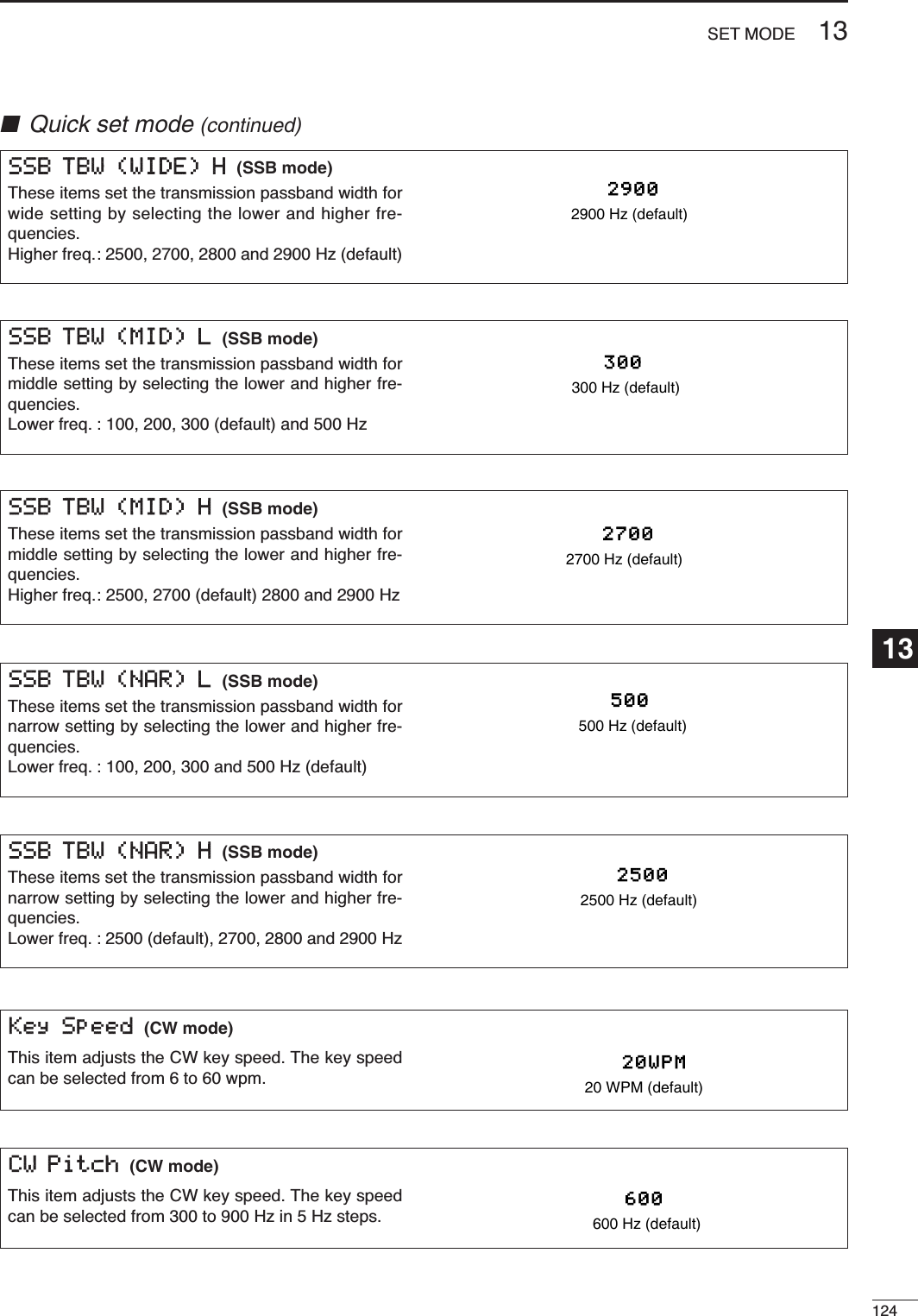
![12513 SET MODE■Quick set mode (continued)Twin Peak Filter (RTTY mode)This item turns the twin peak filter ON and OFF. ONTwin peak filter is ONOFFTwin peak filter is OFF. (de-fault)RTTY Mark Frequency (RTTY mode)This item selects the RTTY mark frequency. RTTYmark frequency is switched between 1275, 1615 and2125 Hz.21252125 Hz RTTY mark frequency (default)12751275 Hz RTTY mark frequencyRTTY Shift Width (RTTY mode)This item adjusts the RTTY shift width. There are 3selectable values: 170, 200 and 425 Hz.170170 Hz RTTY shift frequency (default)425425 Hz RTTY shiftfrequencyRTTY Keying Polarity (RTTY mode)This item selects the RTTY keying polarity. Normal orreverse keying polarity can be selected.When reverse polarity is selected, Mark and Spaceare reversed.- Normal : Key open/close = Mark/Space- Reverse : Key open/close = Space/MarkNormalNormal polarity (default)ReverseReverse polaritySide Tone Level Limit (CW mode)This item allows you to set a maximum volume levelfor CW side tones. CW side tones are linked to the[AF] control until a specified volume level is reached— further rotation of the [AF] control will not increasethe volume of the CW side tones.ONCW side tone level is limitedwith [AF] (default)OFFCW side tone level is linkedto [AF]Side Tone Level (CW mode)This item adjusts the CW side tone level from 0% to100% in 1% steps.See p. 43 for details.50%50% (default)](https://usermanual.wiki/ICOM-orporated/242700/User-Guide-602836-Page-134.png)
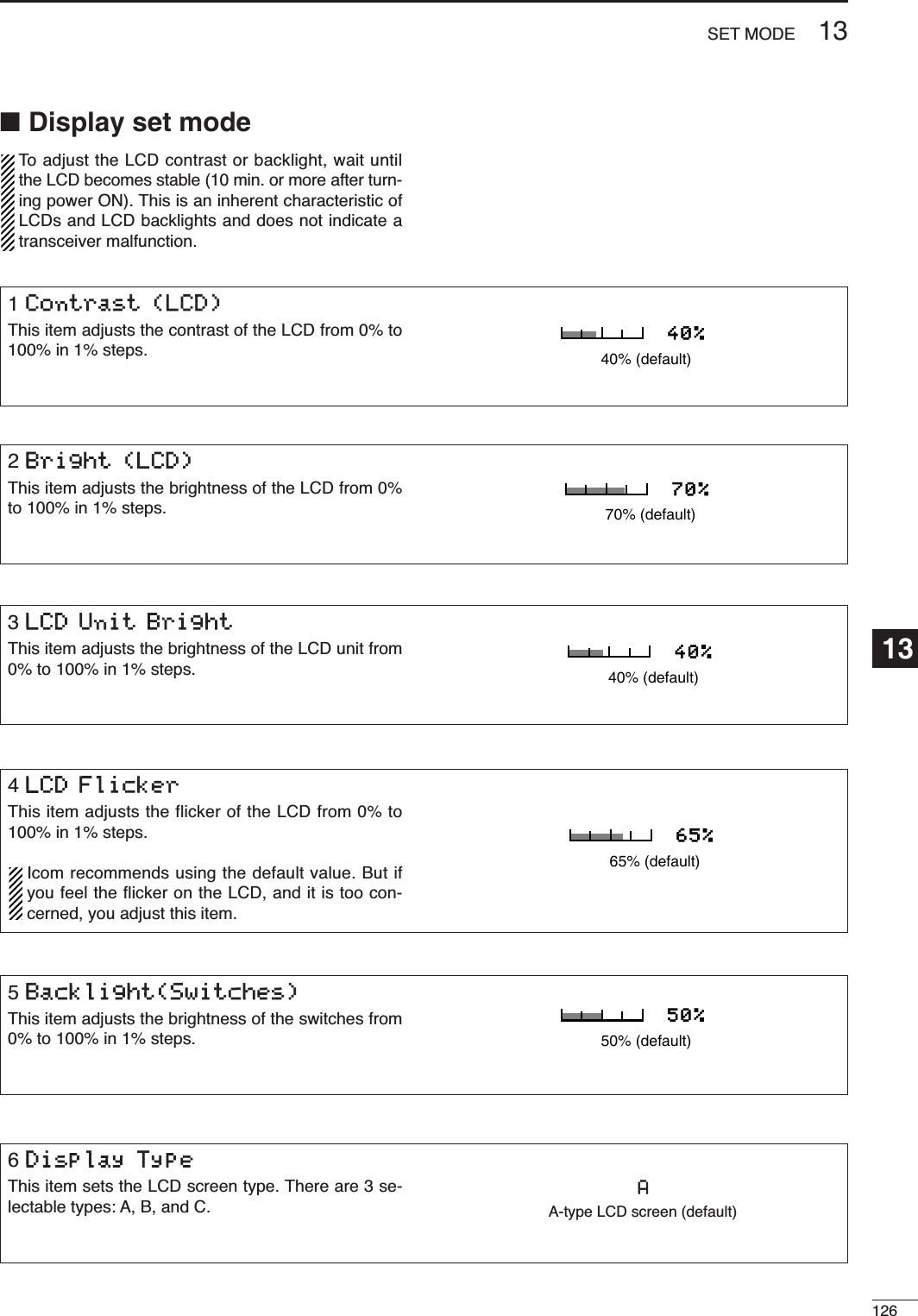
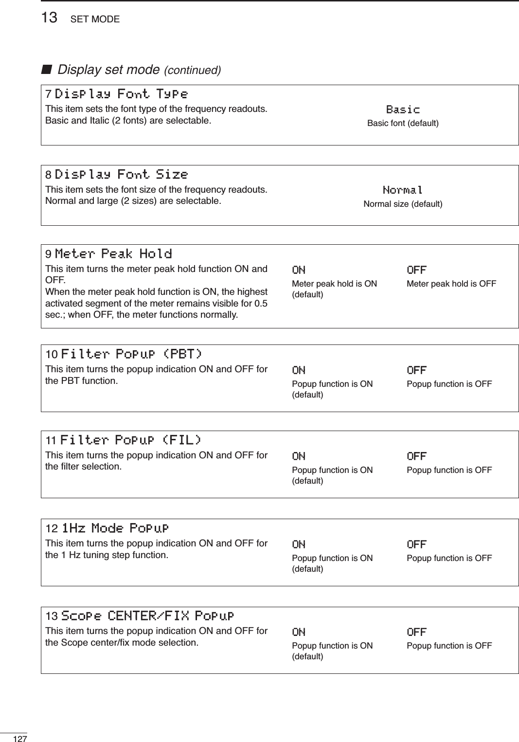
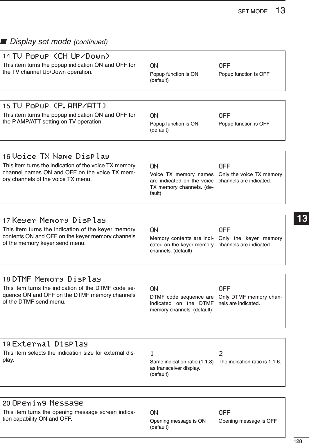
![12913 SET MODE■Display set mode (continued)22 Power ON CheckThis item selects the indication ON or OFF when turn-ing power ON.ON : The Transceiver briefly displays ‘Your Callsign,’ ‘RF power,’ ‘Auto power OFF timer’ and‘RIT/∂TX frequency’ when turning power ON.• No-programmed or disactivated items are skipped.OFF : The display goes directly to frequency indica-tion at power ON.ONPower ON check is ON.(default)OFFPower ON check is OFF.21 My CallYour call sign, etc. can be displayed in the openingscreen when turning power ON. Up to 10 characterscan be programmed.Capital letters, numerals, some symbols (– / .) andspaces can be used.qPush [AF(SET)] momentarily, then [F-2 DISP]toselect the display set mode.wPush [F-1 ≤]or [F-2 ≥]several times to select the“18 My Call” item.rPush [F-3 EDT]to edit.• A cursor appears and blinks.tInput the desired character by rotating [DIAL] or bypushing the band key (on HM-151) for numberinput.•Push [Y(MENU/GRP)] to select the capital letters([ABC]), numerals ([123]) or symbols ([etc]).•Push [F-1 Å]or [F-2 Ç]for cursor movement.•Push [F-3 DEL]to delete the selected character.•Push [F-4 SPC]to input a space.yPush [Z(MENU/GRP)] to input the set name.• The cursor disappears.uPush [Z(MENU/GRP)] twice to exit the set modescreen.• Opening screen exampleSelectedcharacter](https://usermanual.wiki/ICOM-orporated/242700/User-Guide-602836-Page-138.png)
![13013SET MODE13■Miscellaneous (others) set mode3Beep(Confirmation)A beep sounds each time a switch is pushed to con-firm it. This function can be turned OFF for silent op-eration.The volume level can be set described below.ONConfirmation beep ON(default)OFFConfirmation beep OFF4Beep(Band Edge)A beep sounds when an operating frequency entersor exits an amateur band. This functions independentof the confirmation beep setting (above).The volume level can be set described below.ONBand edge beep ON(default)OFFBand edge beep OFF5Beep LevelThis item adjusts the volume level for (confirmationand band edge) beep tones from 0% to 100% in 1%steps. When beep tones are turned OFF, this settinghas no effect.50%50% (default)1MonitorThis item sets the TX monitor function ON and OFF.The monitor gain can be set described below.ONTX monitor function isturned ON.OFFTX monitor function isturned OFF. (default)2Monitor LevelThis item adjusts the transmit IF signal monitor levelfrom 0% to 100% in 1% steps.See p. 89 for details.50%50% (default)6Beep Level LimitThis item allows you to set a maximum volume levelfor (confirmation and band edge) beep tones. Thebeep tones are linked to the [AF] control until a spec-ified volume level is reached — further rotation of the[AF] control will not increase the volume of the beeptones.ONBeep level is limited with[AF] (default)OFFBeep level is linked to [AF]](https://usermanual.wiki/ICOM-orporated/242700/User-Guide-602836-Page-139.png)
![13113 SET MODE7RF/SQL ControlThe [RF/SQL] control can be set as the RF/squelchcontrol (default), the squelch control only (RF gain isfixed at maximum) or ‘Auto’ (RF gain control in SSB,CW and RTTY; squelch control in AM and FM).See pgs. 1, 35 for details.RF+SQL [RF/SQL] control as RF/squelch controlSQL [RF/SQL] control as squelch controlAUTO [RF/SQL] control as RF gain control in SSB,CW and RTTY; squelch control in AM andFM (default)■Miscellaneous (others) set mode (continued)8Quick SPLITWhen this item is set to ON, pushing and holding [F-1SPL](M-1) for 1 sec. sets the undisplayed VFO fre-quency to the displayed VFO frequency plus the splitoffset and activates split operation.See p. 92 for details.ONQuick split ON(default)OFFQuick split OFF10 SPLIT LOCKWhen this item is ON, [DIAL] can be used to adjustthe transmit frequency while pushing [XFC] evenwhile the lock function is activated.See p. 91 for split frequency operation details.ONSplit lock function ONOFFSplit lock function OFF(default)9SPLIT OffsetThis item sets the offset (difference between transmitand receive frequencies) for the quick split function. The offset frequency can be set from –9.999 MHz to+9.999 MHz in 1 kHz steps.0.000MHz0.000 MHz offset(default)-9.999MHzMinus 9.999 MHz offset12 DUP Offset 50MThis item sets the offset (difference between transmitand receive frequencies) for duplex operation. How-ever, this setting is used to input the repeater offsetfor the 50 MHz band.The offset frequency can be set from 0.000 MHz to+9.999 MHz in 1 kHz steps.0.500MHz0.5 MHz offset (default)11 DUP Offset HFThis item sets the offset (difference between transmitand receive frequencies) for duplex operation. How-ever, this setting is used to input the repeater offsetfor an HF band only.The offset frequency can be set from 0.000 MHz to+9.999 MHz in 1 kHz steps.0.100MHz0.1 MHz offset (default)](https://usermanual.wiki/ICOM-orporated/242700/User-Guide-602836-Page-140.png)
 is pushed and held for 1 sec.,the selected offset direction and programmed duplexoffset frequency (depending on the operating fre-quency band) is set with the displayed frequency.DUP-Minus offset direction is se-lected. (default)OFFOne touch repeater functionis OFF.14 DUP Offset 430MThis item sets the offset (difference between transmitand receive frequencies) for duplex operation. How-ever, this setting is used to input the repeater offsetfor the 430 MHz band.The offset frequency can be set from 0.000 MHz to+9.999 MHz in 1 kHz steps.5.000MHz5 MHz offset (default)13 DUP Offset 144MThis item sets the offset (difference between transmitand receive frequencies) for duplex operation. How-ever, this setting is used to input the repeater offsetfor an 144 MHz band only.The offset frequency can be set from 0.000 MHz to+9.999 MHz in 1 kHz steps.0.600MHz0.6 MHz offset (default)17 Tuner (Auto Start)The optional AT-180 ANTENNA TUNERhas an automaticstart capability which starts tuning if the SWR ishigher than 1.5–3:1.When “OFF” is selected, the tuner remains OFF evenwhen the SWR is poor (1.5–3:1). When “ON” is se-lected, automatic tune starts even when the tuner isturned OFF.Even when “ON” is selected, automatic tune doesnot start for the 50 MHz band.ONAutomatic tune function isON.OFFAutomatic tune function isOFF. (default)16 Auto RepeaterThis item turns the auto repeater function ON-1 (autoduplex setting), ON-2 (auto duplex setting and acti-vating tone encoder) or OFF.See p. 65 for details concerning the auto repeaterfunction.ON-1Auto duplex setting is ON.(default)OFFAuto repeater function isOFF.](https://usermanual.wiki/ICOM-orporated/242700/User-Guide-602836-Page-141.png)
![13313 SET MODE20 VSEND SelectThis item select the [ACC] (pin 7) output. “ON” : VSEND is for the 144/430 MHz; HSENDis for the HF/50 MHz.“UHF Only”: VSEND is for the 430 MHz; HSEND isfor the HF/50/144 MHz.“OFF” : VSEND is not used; HSEND is for allbands.ONVSEND is for 144/430 MHz.(default)■Miscellaneous (others) set mode (continued)19 [TUNER] SwitchYou can set [TUNER/CALL] key’s action from “Auto”and “Manual.” Auto Optional antenna tuner is activated auto-matically when tuner is ON. (default)Manual Optional antenna tuner is activated,when [TUNER/CALL] is pushed.18 Tuner (PTT Start)When an optional AH-4 ANTENNA TUNERis connected,tuning can be started automatically at the moment thePTT is pushed.This function activates for HF band only.ONTuning starts when pushing[PTT] on a new frequency.OFFTuning starts only when[TUNER] is pushed. (default)22 SPEECH LanguageThis item selects language for the speech function. You can select between English and Japanese as theSPEECH language.EnglishEnglish announcement(default)JapaneseJapanese announcement23 SPEECH SpeedThis item selects the speech speed between faster orslower synthesizer output.HIGHFaster announcement(default)LOWSlower announcement21 SPEECH LevelThis item adjusts the volume level for speech functionfrom 0% to 100% in 1% steps.50%50% (default)](https://usermanual.wiki/ICOM-orporated/242700/User-Guide-602836-Page-142.png)
![13413SET MODE13■Miscellaneous (others) set mode (continued)24 SPEECH S-LevelYou can have frequency, mode and signal level an-nouncement. Signal level announcement can be de-activated if desired.When “OFF” is selected, the signal level is not an-nounced.ONSignal level announcement(default)OFFNo signal level announcement25 SPEECH [MODE] SwitchThis irem selects the operating mode speech capa-bility when [MODE] is pushed.When “ON” is selected, the selected operating modeis announced at pushing [MODE].ONOperating model announce-ment with [MODE]OFFNo operating mode an-nouncement with [MODE](default)26 Memopad NumbersThis item sets the number of memo pad channelsavailable. 5 or 10 memo pads can be set.55 memo pads(default)1010 memo pads29 MAIN DIAL Auto TSThis item sets the auto tuning step function. When ro-tating [DIAL] rapidly, the tuning step automaticallychanges several times as selected. There are 2 type of auto tuning steps: HIGH (Fastest)and LOW (Faster).HIGH Auto tuning step is turned ON. Fastest tuning step during rapid rotation(default)LOW Auto tuning step is turned ON. Faster tuning step during rapid rotationOFF Auto tuning step is turned OFF.27 SCAN SpeedThis item sets the rate at which channels or frequen-cies are scanned during scan operations. High andlow can be selected.HIGHScan is faster. (default)LOWScan is slower.28 SCAN ResumeThis item sets the scan resume function ON and OFF.“ON” : Scan resumes 10 sec. after stopping ona signal (or 2 sec. after a signal disap-per).“OFF” : Scan does not resume after stopping ona signal. For the priority watch, setting toOFF pauses the watch until the signaldisappears and scan resumes.ONScan resume function isON. (default)OFFScan resume function isOFF.](https://usermanual.wiki/ICOM-orporated/242700/User-Guide-602836-Page-143.png)
![13513 SET MODE■Miscellaneous (others) set mode (continued)30 HM-151 [F-1]This item programmes for one of several functions to[F-1] key of HM-151. Programmable key assignmentsare described as below.MPWMemo pad write is pro-grammed. (default)ANFAuto notch filter is pro-grammed.31 HM-151 [F-2]This item programmes for one of several functions to[F-2] key of HM-151. Programmable key assignmentsare same as above.MPRMemo pad read is pro-grammed. (default)NBNoise blanker function isprogrammed.34 SSB/CW Synchronous TuningThis item selects the displayed frequency shift func-tion from ON and OFF.When this function is activate, the receiving signalcan be kept to receive even when the operating modeis changed between SSB and CW. The frequency shifting value may differ accordingto the CW pitch setting.ONThe displayed frequencyshifts when the operatingmode is changed betweenSSB and CW.OFFThe displayed frequencydoes not shift.(default)32 MIC Up/Down SpeedThis item sets the rate at which frequencies arescanned when the microphone (HM-151) [Y]/[Z]keys are pushed and held. High or low can be se-lected.HIGHHigh speed (default, 50 tuning steps/sec.)LOWLow speed (25 tuning steps/sec.)33 Quick RIT/∂TX ClearThis item selects the RIT/∂TX frequency clearing in-struction with [F-3 CLR]key.See pgs. 75, 88 for deatails.ONClears the RIT/∂TX fre-quency when [F-3 CLR]ispushed momentarily. OFFClears the RIT/∂TX fre-quency when [F-3 CLR]ispushed and held for 1 sec. (default)“P.AMP/ATT” (Preamplifier/attenuator),“NB” (Noise blanker), “NR” (Noise reduction), “MNF” (Manual notch filter),“ANF” (Auto notch filter),“TS” (Tuning step), “SPL” (Split operation), “A/B” (VCO A/B selection),“MCL” (Memory clear),“BNK” (Bank selection), “COM” (Speech compressor),“AGC” (AGC selection), “TBW” (TX filter width), “DUP” (Duplexer), “TON” (FM tone operation), “MET” (Meter selection), “VSC” (Voice squelch control),“MPW” (Memo pad write), “MPR” (Memo pad read), “<SCOPE>” (Scope selection), “<METER>” (Multi-meter selection)](https://usermanual.wiki/ICOM-orporated/242700/User-Guide-602836-Page-144.png)
 is pushed, from “KEYER-SEND” or“KEYER-Root.”KEYER-SENDKeyer send menu is se-lected. (default)KEYER-RootKeyer root menu is selected.38 DTMF 1st MenuThis item selects the first appearing menu when [F-2DTM](S-1) is pushed, from “DTMF-SEND” or“DTMF-Root.”DTMF-SENDDTMF send menu is se-lected. (default)DTMF-RootDTMF root menu is se-lected.36 VOICE 1st MenuThis item selects the first appearing menu when [F-1VO](S-1) is pushed, from “VOICE-RX/TX” or“VOICE-Root.”VOICE-RX/TXVoice RX/TX menu is se-lected. (default)VOICE-RootVoice root menu is selected.39 Mode Select (SSB)This item inhibits the selection of SSB (LSB/USB)modes, and allows you to simplify operation duringnormal operation. For example if you are operating mobile and only planon using FM and AM modes, sets all other modes(SSB, CW, RTTY, WFM) to OFF, thereby making se-lection of AM or FM quick and easy.ONSSB modes are selectable.(default)OFFSSB modes are inhibited.40 Mode Select (CW)This item inhibits the selection of CW/CW-R modes,and allows you to simplify operation during normal op-eration.ONCW modes are selectable. (default)OFFCW modes are inhibited.41 Mode Select (RTTY)This item inhibits the selection of RTTY/RTTY-Rmodes, and allows you to simplify operation duringnormal operation. ONRTTY modes are selectable. (default)OFFRTTY modes are inhibited.](https://usermanual.wiki/ICOM-orporated/242700/User-Guide-602836-Page-145.png)
![45 External Keypad (VOICE)This item sets the external keypad capability andfunction.For your informationThe following diagram shows the equivalent circuit ofan external keypad and connects to the pin 3 andpin 7 of the [MIC] connector (p. 10). ON : Pushing one of external keypad switches, transmitsthe desired voice memory contents during a phonemode (SSB, AM, FM) operation.OFF : External keypad does not function. (default)To [MIC] connector pin eTo [MIC] connector pin u1.5k1±5%1.5k1±5%2.2k1±5%4.7k1±5%S1(T1/M1)S2(T2/M2)S3(T3/M3)S4(T4/M4)USER EXTERNAL KEYPAD46 External Keypad (KEYER)This item sets the external keypad capability andfunction.User external keypad is same as above.ON : Pushing one of external keypad switches, transmitsthe desired memory keyer contents during CWmode operation. OFF : External keypad does not function. (default)13713 SET MODE■Miscellaneous (others) set mode (continued)43 Mode Select (FM)This item inhibits the selection of FM mode, and al-lows you to simplify operation during normal opera-tion.ONFM mode is selectable.(default)OFFFM mode is inhibited.44 Mode Select (WFM)This item inhibits the selection of WFM mode, and al-lows you to simplify operation during normal opera-tion.ONWFM mode is selectable.(default)OFFWFM mode is inihibited.42 Mode Select (AM)This item inhibits the selection of AM mode, and al-lows you to simplify operation during normal opera-tion.ONAM mode is selectable. (default)OFFAM mode is inhibited.](https://usermanual.wiki/ICOM-orporated/242700/User-Guide-602836-Page-146.png)
![13813SET MODE13■Miscellaneous (others) set mode (continued)48 CI-V Baud RateThis item sets the data transfer rate. 300, 1200, 4800,9600, 19200 bps and “Auto” are available.When “Auto” is selected, the baud rate is automati-cally set according to the connected controller or re-mote controller.AutoAuto baud rate(default)1920019200 bps49 CI-V AddressTo distinguish equipment, each CI-V transceiver hasits own Icom standard address in hexadecimal code.The IC-7000’s address is 70h.When 2 or more IC-7000’s are connected to an op-tional CT-17 CI-V LEVEL CONVERTER, rotate [DIAL] toselect a different address for each IC-7000 in therange 01h to 7Fh.70hAddress of 70h(default)7FhAddress of 7Fh50 CI-V TransceiveTransceive operation is possible with the IC-7000con-nected to other Icom HF transceivers or receivers.When “ON” is selected, changing the frequency, op-erating mode, etc. on the IC-7000 automaticallychanges those of connected transceivers (or re-ceivers) and vice versa.ONTransceive ON(default)OFFTransceive OFF51 REF AdjustThis item adjusts the internal reference frequencywithin 0 to 100% range in 1 % steps.47 Front Keypad TypeThis item selects the front keypad type connected tothe [MIC] connector of the controller.Dot/DashDot/Dash (default)Ext KeypadExternal keypad](https://usermanual.wiki/ICOM-orporated/242700/User-Guide-602836-Page-147.png)
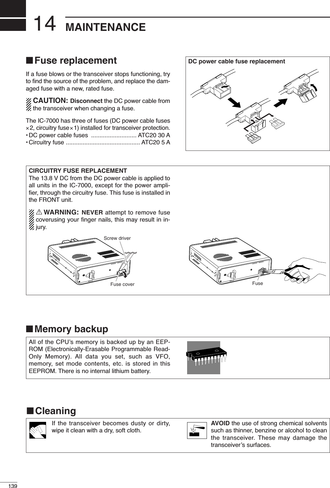
![15140TROUBLESHOOTINGThe following chart is designed to help you correctproblems which are not equipment malfunctions.If you are unable to locate the cause of a problem orsolve it through the use of this chart, contact your near-est Icom Dealer or Service Center.PROBLEMPOWER SUPPLYRECEIVEPOSSIBLE CAUSE SOLUTION REF.Power does not come on when [PWR] key is pushed.No sound comes from the speaker.Sensitivity is low.Receive audio is distor-ted.Receive signal is distor-ted with strong signals.DC power cable is improperly connected.Fuse is blown.Battery is exhausted if you are using a 12 V battery as the power source.Reconnect the power cable correctly.Check for the cause, then replace the fuse with a spare one.(Fuses are installed in two places. One is installed in the DC power cable and the other is installed in the FRONT unit.Check the battery voltage.p. 19p. 139—pgs. 1,25, 33pgs. 1, 25, 35—p. 18——pgs.116, 117p. 74p. 34p. 79p. 80p. 74Volume level is set too low.The squelch is closed.The transceiver is in the transmitting condition.An external speaker or headphones are connected.The antenna is not connected properly.The antenna feed line is cut or shorted.The antenna is not properly tuned.The attenuator function is activated.The operating mode is not selected correctly.The PBT function is activated.Noise blanker function is activated.Preamp is activated.Rotate [AF] clockwise to obtain a suit-able listening level.Rotate [SQL] counterclockwise to open the squelch.Release [PTT] on the microphone or check the SEND line of an external unit, if connected.Check the external speaker or head-phone plug connection.Reconnect to the antenna connector.Check the feed line and correct any improper conditions.Push [TUNE/CALL] to manually tune the antenna.Push [P.AMP/ATT] to turn the function OFF.Select a suitable operating mode.Push [PBT/M-ch/RIT(CLR)] for 1 sec. to clear the PBT function.Push[NB/ADJ]to turn the function OFF.Push [P.AMP/ATT] to turn the function OFF.1415](https://usermanual.wiki/ICOM-orporated/242700/User-Guide-602836-Page-149.png)
![14115 TROUBLESHOOTINGPROBLEMTRANSMITDISPLAYSCANPOSSIBLE CAUSE SOLUTION REF.Transmitting is impossi-ble.Output power is too low. No contact possible with other stations. Repeater cannot be ac-cessed.Transmitted signals are distorted.Displayed frequency does not change proper-ly.Programmed scan does not stop.Programmed scan does not start.Memory scan does not start.Memory select scan does not start.The operating frequency is not set to a ham band. Power is set to a lower power than maximum.Microphone gain is set too low.The antenna is not connected properly.The antenna feed line is cut or shorted.The antenna is not properly tuned.RIT function is activated.Split function is activated.Split function is not activated.An incorrect transmit frequency is set.Subaudible tone encoder is OFF and repeater requires a tone for access.Programmed subaudible tone fre-quency is wrong.Microphone gain is set too high.The compression level is set too high with the speech compressor ON.The dial lock function is activated.The internal CPU has malfunctioned.Squelch is open.The same frequencies have been programmed in scan edge memory channels.2 or more memory channels have not been programmed.2 or more memory channels have not been designated as select channels.Set squelch to the threshold position.Programm different frequencies into scan edge memory channels.Program 2 or more memory chan-nels.Designate 2 or more memory chan-nels as select channels for the scan.Set gain in quick set mode.Set compression level to a suitable position.Push [SPCH/LOCK] to deactivate the function.Reset the CPU.(While pushing [Y(BAND)] and [Z(BAND)],push [PWR] to turn power ON.Push [F-1 SPL] in the M-1menu to turn the function ON.Set the proper frequencies into VFO A and B or into one of the memory channels.Use[F-3 TON] in the M-3menu to se-lect FM-TONE.Program the required frequency using FM tone set mode.Push [F-1 RIT] in the RIT/∂TX mode to turn the function OFF.Push [F-1 SPL] in the M-1menu to turn the function OFF.Set the output power in quick set mode/initial set mode.Set microphone gain to a suitable position using quick set mode.Reconnect the antenna connector.Check the feed line and correct any improper conditions.Push [TUNE/CALL] to manually tune the antenna.Set the frequency to a ham band. p. 29p. 38p. 38——pgs.116, 117p. 75p. 91p. 91p. 27p. 63p. 64p. 38p. 89p. 37p. 25p. 35p. 103p. 103p. 106](https://usermanual.wiki/ICOM-orporated/242700/User-Guide-602836-Page-150.png)
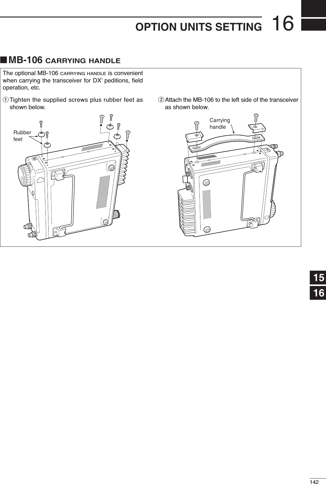
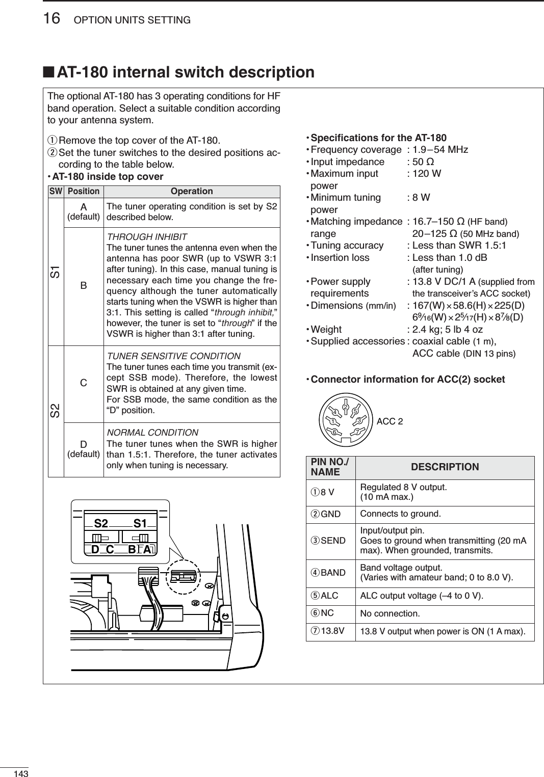
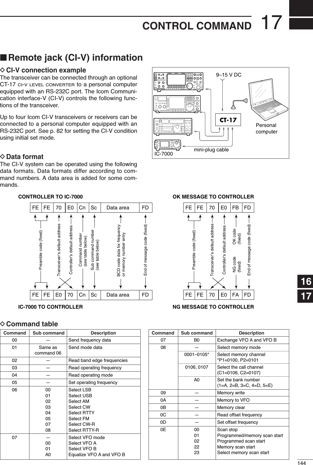
![• Command table (continued)0E B0 Set as non-select channelB1 Set as select channelD0 Set scan resume OFFD3 Set scan resume ON0F 00 Turn the split function OFF01 Turn the split function ON10 Select simplex operation11 Select –DUP operation12 Select +DUP operation10 00 AM/FM/WFM modes:Select 10 Hz (1 Hz) tuning stepSSB/CW/RTTY modes: TS OFF01 Select 100 Hz tuning step02 Select 1 kHz tuning step03 Select 5 kHz tuning step04 Select 9 kHz tuning step05 Select 10 kHz tuning step06 Select 12.5 kHz tuning step07 Select 20 kHz tuning step08 Select 25 kHz tuning step09 Select 100 kHz tuning step10 AM/FM/WFM modes:Select MHz stepSSB/CW/RTTY modes: TS OFF11 — Select/read attenuator (0=OFF,12=ON (12 dB))13 00 Announce with voice synthesizer01 (00=all data; 01=frequency and 02 S-meter level; 02=receive mode)14 01 + Level data [AF] level setting (0=max. CCW to255=max. CW)02 + Level data [RF] level setting (0=max. CCW to255=11 o’clock)03 + Level data [SQL] level setting (0=11 o’clock to255=max. CW)06 + Level data NR level setting (0=min. to255=max.)07 + Level data Inside [PBT] setting or IF shiftsetting (0=max. CCW, 128=cen-ter, 255=max. CW)08 + Level data Outside [PBT] setting(0=max. CCW, 128=center,255=max. CW)09 + Level data CW Pitch setting (0=300 Hz,128=600 Hz, 255=900 Hz, in 5 Hzsteps)0A + Level data RF Power setting (0=mini. to255=max.)0B + Level data MIC Gain setting (0=mini. to255=max.)0C + Level data Key Speed setting (0=slow to255=fast)0D + Level data NOTCH (NF1) frequency setting(0=low freq. to 255=high freq.)0E + Level data COMP Level setting (0=0 to10=10)0F + Level data Break-IN DELAY setting (20=2.0dto 130=13.0d)12 + Level data NB level setting (0=0 to255=100%)15 + Level data Monitor gain setting (0=0 to255=100%)16 + Level data VOX gain setting (0=0 to255=100%)14 17 + Level data Anti-VOX gain setting (0=0 to255=100%)18 + Level data Contrast (LCD) setting (0=0 to255=100%)19 + Level data Bright (LCD) setting (0=0 to255=100%)1A + Level data NOTCH (NF2) frequency setting(0=low freq. to 255=high freq.)15 01 Read squelch condition02 Read S-meter level11 Read RF power meter 12 Read SWR meter 13 Read ALC meter 14 Read COMP meter16 02 Preamp (0=OFF; 1=ON)12 AGC selection (0=OFF; 1=Slow;2=Mid; 3=Fast)22 Noise blanker (0=OFF; 1=ON)40 Noise reduction (0=OFF; 1=ON)41 Auto notch (0=OFF; 1=ON)42 Repeater tone (0=OFF; 1=ON)43 Tone squelch (0=OFF; 1=ON)44Speech compressor (0=OFF; 1=ON)45 Monitor (0=OFF; 1=ON)46 VOX function (0=OFF; 1=ON)47 Break-in (0=OFF; 1=semi break-in; 2=full break-in)48Manual notch (NF1) (0=OFF; 1=ON)4B DTCS (0=OFF; 1=ON)4C VSC (0=OFF; 1=ON)4F Twin Peak Filter (0=OFF; 1=ON)50 Dial lock function (0=OFF, 1=ON)51Manual notch (NF2) (0=OFF, 1=ON)19 00 Read the transceiver ID1A 00 Send/read memory contents (seep. 148 for details)01 Send/read band stacking registercontents (see p. 148 for details)02 Send/read memory keyer contents(see p. 148 for details)03 Send/read the selected filter width(SSB, CW, RTTY: 0=50 Hz to31=2700 Hz; AM: 0=200 Hz to49=10 kHz)04 Send/read the selected AGC timeconstant (0=OFF, 1=0.1/0.3 sec. to13=6.0/8.0 sec.)050001 RF Power setting (0=mini. to255=max.)050002 MIC Gain setting (0=mini. to255=max.)050003 Send/read of SSB TX bandwidth(lower edge) for wide(0=100, 1=200, 2=300, 3=500 HZ)050004 Send/read of SSB TX bandwidth(higher edge) for wide (0=2500,1=2700, 2=2800, 3=2900 HZ)050005 Send/read of SSB TX bandwidth(lower edge) for middle(0=100, 1=200, 2=300, 3=500 HZ)050006 Send/read of SSB TX bandwidth(higher edge) for middle (0=2500,1=2700, 2=2800, 3=2900 HZ)Command Sub command Description Command Sub command Description14517 CONTROL COMMAND](https://usermanual.wiki/ICOM-orporated/242700/User-Guide-602836-Page-154.png)
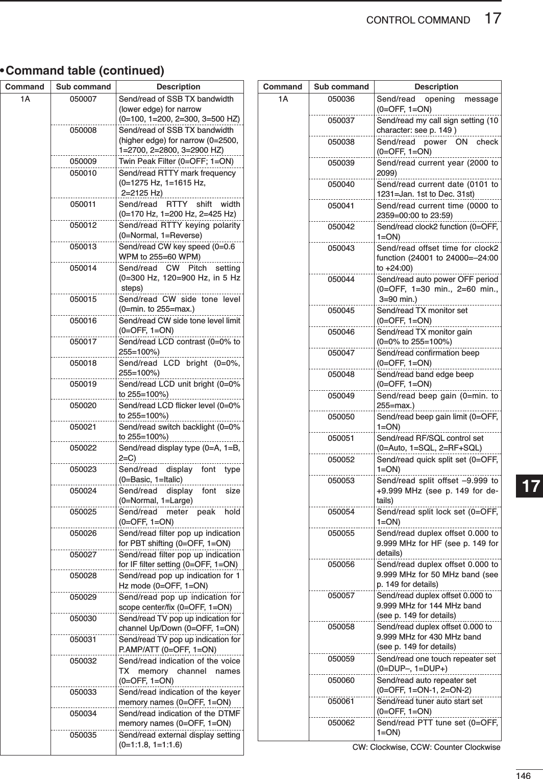
![14717 CONTROL COMMAND• Command table (continued)1A 050087 Send/read FM mode selectability(0=OFF: inhibition, 1=ON: selec-table)050088 Send/read WFM mode selectabil-ity (0=OFF: inhibition, 1=ON: se-lectable)050089 Send/read external keypad setfor voice memory (0=OFF, 1=ON)050090 Send/read external keypad setfor keyer memory (0=OFF, 1=ON)050091 Send/read external keypad typeconnected to [MIC] connector ofcontroller (0=Dot/Dash type,1=Ext Keypad)050092 Send/read CI-V transceive set(0=OFF, 1=ON)050093 Send/read reference frequencyset (0=0 to 255=100%)050094 Send/read speech compresserlevel (0=0 to 10=10)050095 Send/read auto voice monitor set(0=OFF, 1=ON)050096 Send/read MIC memo function(0=OFF, 1=ON)050097 Send/read contest number style (0=Normal, 1=190AANO,2=190AANT, 3=90ANO,4=90ANT)050098 Send/read count up trigger chan-nel (1=M1, 2=M2, 3=M3, 4=M4)050099 Send/read present number(1–9999)050100 Send/read CW keyer repeat time(1=1 sec. to 60=60 sec.)050101 Send/read CW keyer dot/dashratio (28=1:1:2.8 to 45=1:1:4.5)050102 Send/read rise time (0=2 msec.,1=4 msec., 2=6 msec.,3=8 msec.)050103 Send/read CW paddle polarity (0=Normal, 1=Reverse)050104 Send/read CW keyer type(0=Straight, 1=Bug-key, 2=ELEC-Key)050105 Send/read MIC up/down keyer(HM-103) set (0=OFF, 1=ON)050106 Send/read RTTY decode USOS(0=OFF, 1=ON)050107 Send/read RTTY decode new linecode (0=CR,LF,CR+LF, 1=CR+LF)050108 Send/read scope max. hold(0=OFF, 1=ON)050109 Send/read scope size set (0=Nor-mal, 1=Wide)050110 Send/read fast sweep set(0=1 sweep, 1=Continuous)050111 Send/read fast sweep audio level(0=0 dB, 1=–10 dB, 2=OFF)050112 Send/read NB level set(0=min. to 255=max.)050113 Send/read NB width set(0=min. to 255=max.)1A 050063 Send/read [TUNER/CALL] key ac-tion set (0=Manual, 1=Auto)050064 Send/read [ACC] (pin 7) output“VSEND” set (0=OFF, 1=UHFonly, 2=ON)050065 Send/read speech level (0=0 to255=100%)050066 Send/read speech language(0=English, 1=Japanese)050067 Send/read speech speed (0=Slow,1=Fast)050068 Send/read S-level speech(0=OFF, 1=ON)050069 Send/read speech capability with[MODE] key operation (0=OFF, 1=ON)050070 Send/read memopad numbers(0=5 ch, 1=10 ch)050071 Send/read scan speed (0=Low, 1=High)050072 Send/read scan resume (0=OFF, 1=ON)050073 Send/read main dial auto TS(0=OFF, 1=Low, 2=High)050074 Send/read [F-1] key assigment ofthe HM-151. (0=“P.AMP/ATT,”1=“NB,” 2=“NR,” 3=“MNF,”4=“ANF,” 5=“TS,” 6=“SPL,”7=“A/B,” 8=“MCL,” 9=“BNK,”10=“COM,” 11=“AGC,” 12=“TBW,”13=“DUP,” 14=“TON,” 15=“MET,”16=“VSC,” 17=“MPW,” 18=“MPR,”19=“<SCOPE>,” 20=“<METER>”)050075 Send/read [F-2] key assigment ofthe HM-151. (Selectable functionsare same as [F-1].)050076 Send/read mic. up/down speed(0=Low, 1=High)050077 Send/read quick RIT/∂TX clearfunction (0=OFF, 1=ON)050078 Send/read SSB/CW synchronoustuning function (0=OFF, 1=ON)050079 Send/read CW normal side set(0=LSB, 1=USB)050080 Send/read voice recorder 1stmenu set (0=Voice-root, 1=Voice-RX/TX)050081 Send/read keyer 1st menu set(0=Keyer-root, 1=Keyer-send)050082 Send/read DTMF 1st menu set(0=DTMF-root, 1=DTMF-send)050083 Send/read SSB mode selectability(0=OFF: inhibition, 1=ON: selec-table)050084 Send/read CW mode selectability(0=OFF: inhibition, 1=ON: selec-table)050085 Send/read RTTY mode selectabil-ity. (0=OFF: inhibition, 1=ON: se-lectable)050086 Send/read AM mode selectability(0=OFF: inhibition, 1=ON: selec-table)Command Sub command Description Command Sub command Description](https://usermanual.wiki/ICOM-orporated/242700/User-Guide-602836-Page-156.png)
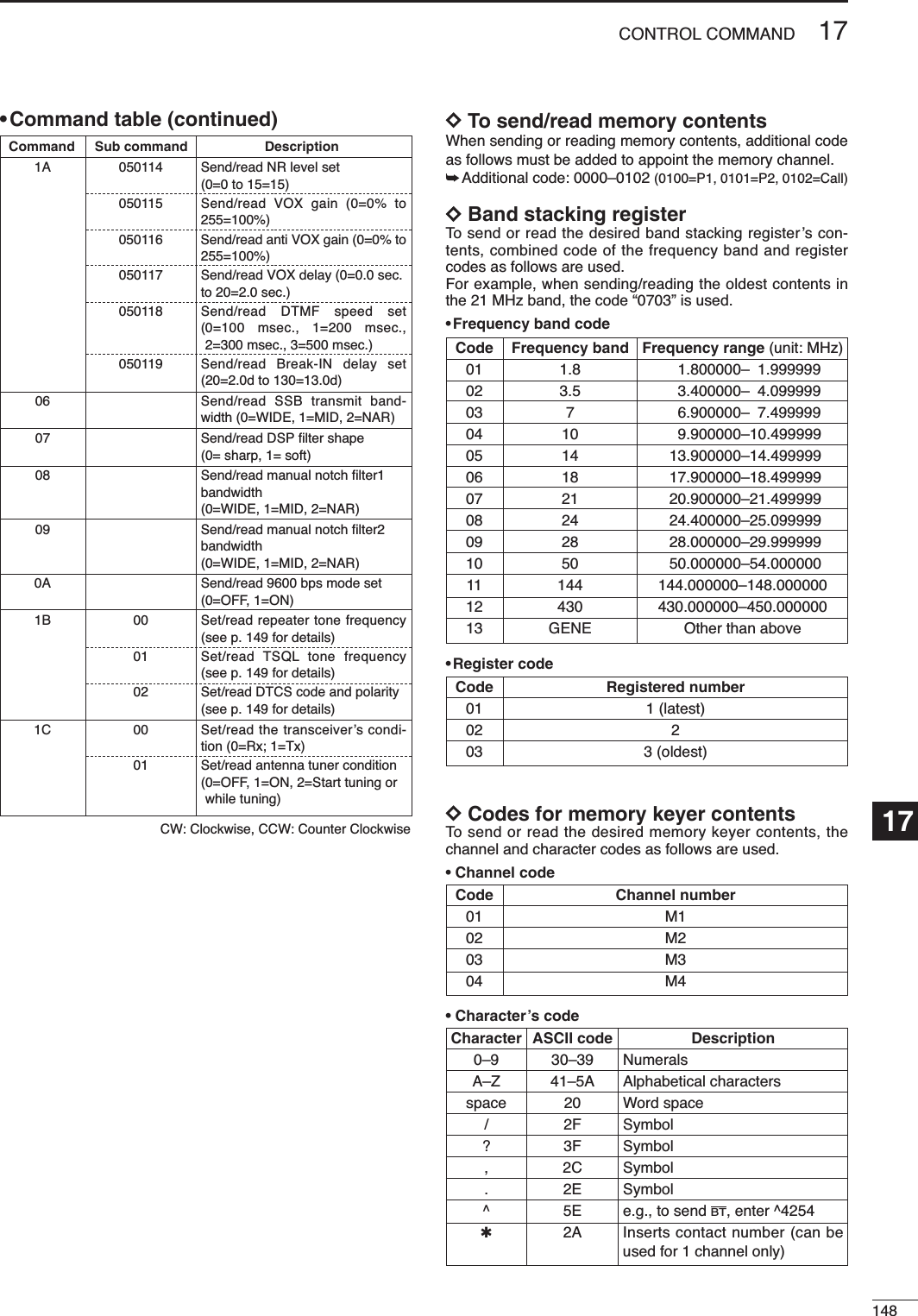
![14917 CONTROL COMMANDDCharacter’s code for my callDCodes for memory name contentsTo send or read the desired memory name settings, the char-acter codes, instructed codes for memory keyer contents asabove, and follows are additionally used. •Character’s code— Alphabetical characters•Character’s code— Symbols DSplit/Duplex frequency settingThe following data sequence is used when sending/readingthe split or duplex frequency setting.DRepeater tone/tone squelch frequencysettingThe following data sequence is used when sending/readingthe DTCS code and polarity setting.DDTCS code and polarity settingThe following data sequence is used when sending/readingthe DTCS code and polarity setting.Fixed digit: 0 1st digit: 0–72nd digit: 0–73rd digit: 0–7Transmit polarity: 0= Normal1= ReverseReceive polarity: 0= Normal1= ReverseqXX0XXweX100Hz digit: 0–210 Hz digit: 0–91 Hz digit: 0–90.1 Hz digit: 0–9Fixed digit: 0*Fixed digit: 0*q*00XXXweX*Not necessary when setting a frequency.1 kHz digit: 0—9100 Hz digit: 0 (fixed)100 kHz digit: 0—910 kHz digit: 0—910 MHz digit: 0 (fixed)1 MHz digit: 0—4Direction:00=+ direction01=— directionq0XXXXXXwe0r**No need to enter for duplex frequency setting.Character ASCII code Character ASCII codea–z 61–7A — —Character ASCII code Character ASCII code!21#23$24%25&26¥5C?3F ” 22’27`60+2B–2D:3A;3B=3D<3C>3E ( 28)29[5B]5D{7B}7D|7C_5F–7E@40Character ASCII code Description0–9 30–39 NumeralsA–Z 41–5A Alphabetical charactersspace 20 Word space – 2D Symbol. 2E Symbol/ 2F Symbol](https://usermanual.wiki/ICOM-orporated/242700/User-Guide-602836-Page-158.png)
![18150SPECIFICATIONS■General• Frequency coverage :Receive30 kHz–199.999999 MHz*1*2400–470.000000 MHz*1*2Transmit1.800–1.999999 MHz*2, 3.500–3.999999 MHz*25.33050*3, 5.34650*3, 5.36650*3,5.37150*3, 5.40350*3,7.000–7.300 MHz*2, 10.100–10.150 MHz*2,14.000–14.350 MHz*2, 18.068–18.168 MHz*2,21.000–21.450 MHz*2, 24.890–24.990 MHz*2,28.000–29.700 MHz*2, 50.000–54.000 MHz*2,144.000–148.000 MHz*2, 430.000 –450.000 MHz*2*1Some frequency bands are not guaranteed.*2Depending on version. *3USA version only.• Mode : SSB, CW, RTTY, AM, FM, WFM(WFM is for receive only)•Number of memory CH: 503 (split memory: 99×5 banks; scanedges: 6; call channel: 2 ) channels• Antenna connector : SO-239×2(for HF/50 MHz and144/430 MHz) /50 •Usable temperature : –10°C to +60°C (+14°F to +140°F)range• Frequency stability : Less than ± 0.5 ppm(0°C to +50°C; +32°F to +122°F)•Power supply : 13.8 V DC±15% (negative ground)requirement•Current drain : Transmit (at 100 W) 22 A(at 13.8 V DC) Receive squelched 1.3 Amax. audio 1.6 A• Dimensions : 167(W) ×58(H) ×180(D) mm, (projections not included) 69⁄16(W) ×29⁄32(H) ×73⁄32(D) in• Weight (approx.) : 2.3 kg (5 lb 1 oz)• CI-V connector : 2-conductor 3.5 (d) mm (1⁄8˝)• Video connector : 2-conductor 3.5 (d) mm (1⁄8˝)• ACC connector : 13-pin• Data connector : 6-pin■Transmitter• Output power :SSB, CW, FM, RTTY 2–100 W (1.8–50 MHz bands)2–50 W (144 MHz band)2–35 W (430 MHz band)AM 1–40 W (1.8–50 MHz bands)2–20 W (144 MHz band)2–14 W (430 MHz band)• Modulation system :SSB Balanced modulationAM Low level modulationFM Variable reactance modulation•Spurious emissions : Less than –60 dB**spurious freq.: below 30 MHz: –50 dB; above 50 MHz: –60 dB• Carrier suppression : More than 50 dB• Unwanted sideband : More than 50 dB•Microphone : 8-pin modular jack (600 )connector•KEY connector : 3-conductor 6.35 (d) mm (1⁄4˝)• RTTY connector : 3-conductor 3.5 (d) mm (1⁄8˝)■Receiver• Receive system :SSB/CW/RTTY/AM/FM Triple-conversion superheterodyneWFM Double-conversion superheterodyne• Intermediate frequencies:1stSSB/CW/RTTY/AM/FM 124.487 MHzWFM 134.732 MHzTV (Video) 69.0100 MHz2ndSSB/CW/RTTY/AM/FM 455 kHzWFM 10.700 MHz3rdSSB/CW/RTTY/AM/FM 16.15 kHz• Sensitivity (at preamp ON):• Squelch sensitivity (threshold; preamp ON) :SSB/CW/RTTY/AM Less than 5.6 µVFM Less than 0.3 µV• Selectivity : SSB* (BW=2.4 kHz) More than 2.4 kHz/–6 dBLess than 3.6 kHz/–60 dBCW* (BW=500 Hz) More than 500 Hz/–6 dBLess than 900 Hz/–60 dBRTTY (BW=350 Hz) More than 360 Hz/–6 dBLess than 650 Hz/–60 dBAM (BW=6 kHz) More than 6.0 kHz/–6 dBLess than 15.0 kHz/–60 dBFM (BW=15 kHz) More than 12.0 kHz/–6 dBLess than 20.0 kHz/–60 dB*IF filter shape is set to SHARP.•Spurious and image rejection ratio:HF bands More than 70 dB50 MHz band More than 70 dB (except IF/2 through)144/430 MHz band More than 65 dB (except IF through)• Audio output power : More than 2.0 W at 10% distortionwith an 8 load (at 13.8 V DC)• RIT variable range : ±9.99 kHz• PHONES connector : 3-conductor 3.5 (d) mm (1⁄8˝)/8 • EXT SP connector : 2-conductor 3.5 (d) mm (1⁄8˝)/8 1718Frequencyrange[MHz]SSB/CW/RTTY10 dB S/NAM10 dB S/NFM12 dB SINADWFM12 dB SINAD0.5–1.8 —13 µV — —1.8–28 0.15 µV 2.0 µV — —28–29.995 0.5 µV —50 MHz band 0.12 µV 1.0 µV 0.25 µV —76–108 — — — 10.0 µV144/430 MHzbands 0.11 µV 1.0 µV 0.18 µV —](https://usermanual.wiki/ICOM-orporated/242700/User-Guide-602836-Page-159.png)
![MB-105 MOUNTING BRACKETMetal plate for attaching the front panel to awall or other such flat surface.19151OPTIONSAT-180 HF/50 MHz AUTOMATICANTENNA TUNERFully automatic antenna tuner with presetmemories for each 100 kHz. Unique “auto-matic tuner on” function is available. Seep. 89 for AT-180 specifications.AH-4 HF AUTOMATIC ANTENNATUNERSpecially designed to tune a long wire an-tenna for portable or mobile HF/50 MHz op-eration. The “PTT tune” function providessimple operation.• Input power rating: 150 WHM-151 HAND MICROPHONEStandard hand microphone.AH-2b ANTENNA ELEMENTA 2.5 m long antenna ele-ment for mobile operationwith the AH-4.•Frequency coverage7–54 MHz band with theAH-4SM-20 DESKTOP MICROPHONEIncludes [UP]/[DOWN] switches and a lowcut function. The OPC-589 is necessary touse this microphone.SP-7 EXTERNAL SPEAKERCompact speaker for base station opera-tion. Height can be adjusted for your conve-nience.• Input impedance: 8 • Max. input power: 5 WCT-17 CI-V LEVEL CONVERTERUNITFor remote transceiver control using a per-sonal computer equipped with an RS-232Cport. You can change frequencies, operat-ing mode, memory channels, etc., via yourcomputer.SP-10 EXTERNAL SPEAKERExternal speakers suitable for mobile oper-ation.SP-12: Slim-type; 8 /3 WSP-10: Compact-type; 4 /5 WMB-62MOBILE MOUNTING BRACKETMounts the transceiver main body, with orwithout the front panel, inside a vehicle.MB-65 MOUNTING BASEAllows you to conveniently vehicle-mountthe front panel of the IC-7000. An MB-105must be used in combination with the MB-65.MB-106 CARRYING HANDLEConvenient when carrying the transceiver.](https://usermanual.wiki/ICOM-orporated/242700/User-Guide-602836-Page-160.png)
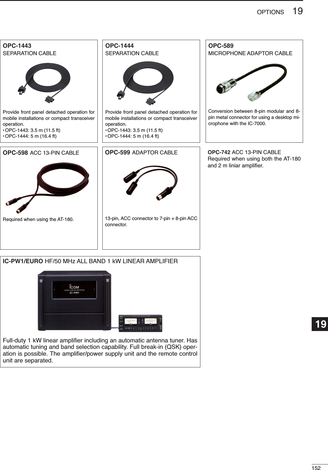
![20153MENU GUIDEMain menu group Sub menu groupGraphic menu groupM-1 SPL A/B FILM-2 MEM MW MCLXFCV/MM-3 VOX COM AGCVOXM-3 DUP TON1/4BRKM-3 AGC1/4M-3 AGC(SSB)(SSB/AM)(CW)(RTTY)(in memory mode)(CW)(RTTY)(FM/WFM)(FM/WFM)BAND scopeMulti function meterSWR meterVO MET VSCS-1VO KEY MET VSCS-1VO DEC MET VSCS-1VO DTM MET VSCS-1SCN PRISELV/M VSCS-2MW MPW MPRS-3G-1BANDscopeG-2Multi function meterG-3VOXM-3 AGCTBW9600(AM)Push[AF]momentarilySet mode menuPushmomentarilyPushfor 1 sec.Push[Z(MENU/GRP)]](https://usermanual.wiki/ICOM-orporated/242700/User-Guide-602836-Page-162.png)
![15420MENU GUIDE20• Set mode menu• Display set mode • Time set mode• Miscellaneous (others) set modeQuick set modeNo.1RF Power RF Power RF Power2MIC Gain Key Speed Twin Peak Filter 345678SSB TBW (WIDE) LSSB TBW (WIDE) HSide ToneLevelSSB TBW (MID) LSide ToneLevel LimitRTTY Mark FrequencyRTTY Shift WidthRTTY Keying PolaritySSB TBW (MID) HSSB TBW (NAR) LSSB TBW (NAR) HCW PitchSSBmodeCWmodeRTTYmodeRF PowerMIC GainAM/FMmodeSet mode descriptionPush [Z(MENU/GRP)] or [AF] switchto return to upper menu](https://usermanual.wiki/ICOM-orporated/242700/User-Guide-602836-Page-163.png)