ICOM orporated 242700 HF/VHF/UHF All Mode Transceiver User Manual IC 7000 UserMan
ICOM Incorporated HF/VHF/UHF All Mode Transceiver IC 7000 UserMan
Users Manual
HF/VHF/UHF
ALL MODE TRANSCEIVER
i7000
INSTRUCTION MANUAL
i-1
IMPORTANT
READ THIS INSTRUCTION MANUAL
CAREFULLY before attempting to operate the
transceiver.
SAVE THIS INSTRUCTION MANUAL. This
manual contains important safety and operating in-
structions for the IC-7000.
EXPLICIT DEFINITIONS
WORD DEFINITION
RWARNING Personal injury, fire hazard or electric
shock may occur.
CAUTION Equipment damage may occur.
NOTE
If disregarded, inconvenience only. No
risk or personal injury, fire or electric
shock.
We understand that you have a choice of many differ-
ent radios in the market place. We want to take a cou-
ple of moments of your time to thank you for making
the IC-7000 your radio of choice, and hope you agree
with Icom’s philosophy of “technology first.” Many
hours of research and development went into the de-
sign of your IC-7000.
D
FEATURES
❍IF DSP features
❍All mode capability covering 160–0.7 m
(depending on version)
❍Compact with detachable front panel
❍±0.5 ppm of high frequency stability
❍Boudot RTTY demodulator
❍Simple band scope function
❍Selectable SSB transmission passband
width (Each for Higher and lower pass fre-
quency)
❍Standard voice synthesizer/voice recorder
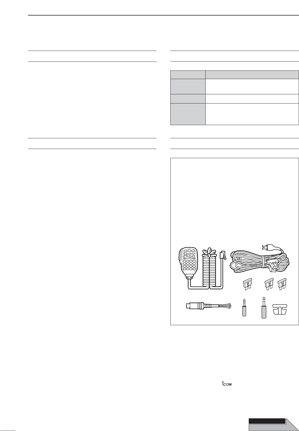
The transceiver comes with the following acces-
sories.
Qty.
qHand microphone (HM-151) ........................... 1
wDC power cable (OPC-1457) .......................... 1
eSpare fuse (ATC 5 A) ...................................... 1
rSpare fuse (ATC 30 A) .................................... 2
tACC cable ........................................................1
y3.5 (d) mm plug ................................................1
u6.5 (d) mm Electronic keyer plug......................1
iMicrophone hanger...........................................1
q
e
t
w
yu
r
i
FOREWORD SUPPLIED ACCESSORIES
Icom, Icom Inc. and the logo are registered trademarks
of Icom Incorporated (Japan) in the United States, the United
Kingdom, Germany, France, Spain, Russia and/or other
countries.
Spurious may be received near the following frequencies.
These are made in the internal circuit and does not indicate a
transceiver malfunction:
52.76497 MHz,
443.03535 MHz
THIS P
THIS PAGE
AGE
OPEN
i-2
SPCH
/LOCK
TUNER
/CALL XFC
V/M
F-1 F-2
FIL
MODE
GENE
MW
123
456
789
.
0
CE
F-INP
ENT
1.8 3.5 7
10 14 18
21 24 28
50 144 430
Mic element
q
e
w
o
!7!8!9@0@2@3@4 @1
t
r
yu !2
!5
!6
!1!0i
!3
!4
z
c
v
bn
m
,
.
⁄0
⁄2
⁄3
⁄1
x
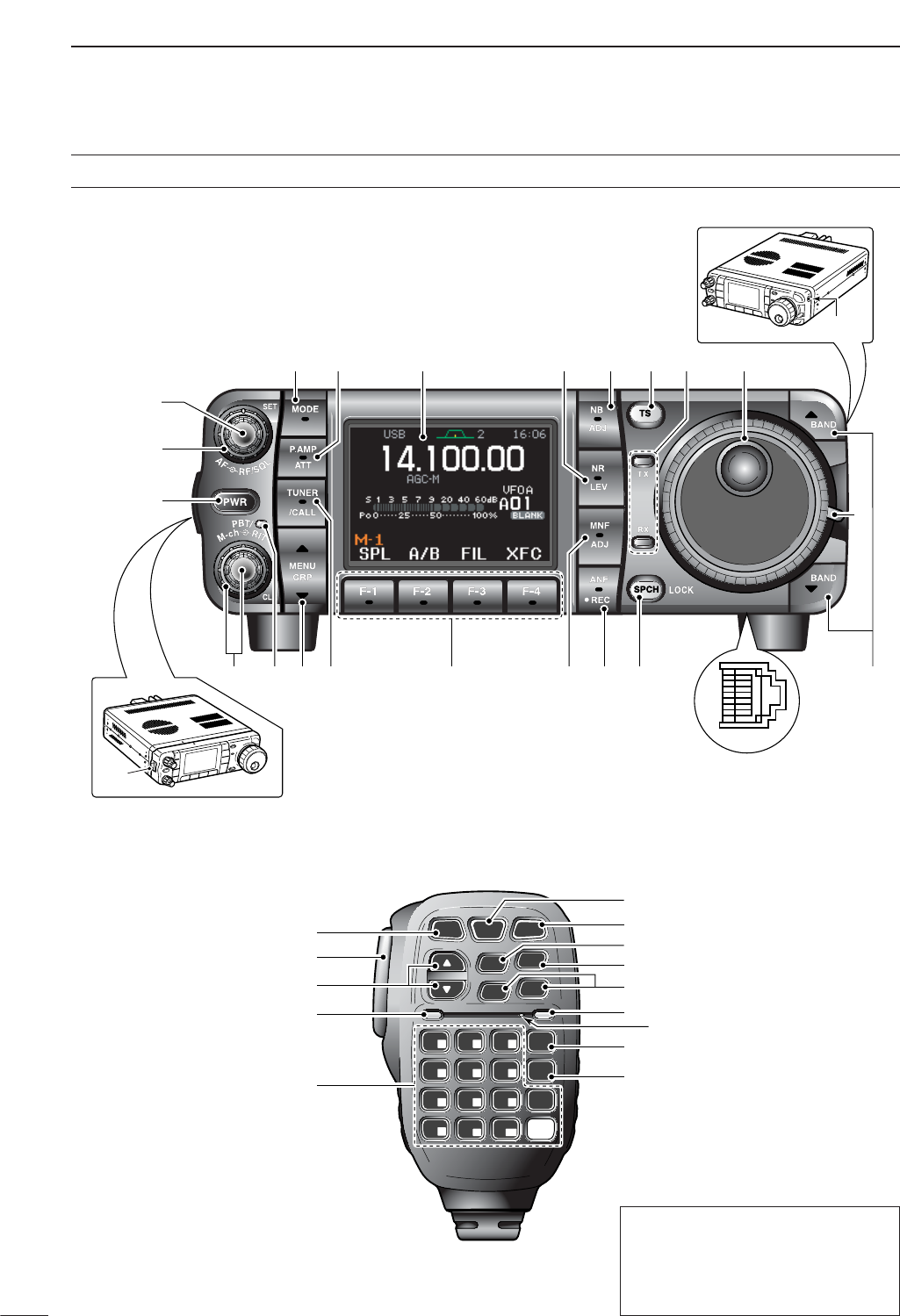
Front panel
HM-151
The front panel and HM-151’s panel
descriptions are descrived between
pages 1 to 4, and on page 9, respec-
tively (see the Chapter 1 (Panel de-
scription) for more details).
ILLUSTRATIONS

i-3
■Front panel
qAF GAIN CONTROL [AF] (inner control; p. 33)
wRF GAIN CONTROL/SQUELCH CONTROL
[RF/SQL] (outer control; p. 35)
ePOWER KEY [PWR] (p. 25)
rFRONT PANEL LATCH (p. 16)
tPASSBAND TUNING/M-ch/RIT CONTROLS
[PBT/M-ch/RIT] (pgs. 75, 79, 88, 102, 106)
yTWIN PBT (M-ch/RIT) INDICATOR
(pgs. 75, 79, 88, 102, 106)
uMENU/GROUP KEYS [MENU/GRP] (p. 153)
iTUNER/CALL KEY [TUNER/CALL]
(pgs. 102, 116)
oMULTI-FUNCTION KEYS [F1]/[F2]/[F3]/[F4]
(pgs. 5–8, 153)
!0 MANUAL NOTCH KEY [MNF/ADJ] (p. 83)
!1 AUTO NOTCH/VOICE RECORDER KEY
[ANF/•REC] (pgs. 82, 95)
!2 SPCH/LOCK KEY [SPCH/LOCK] (pgs. 34, 37)
!3 MICROPHONE CONNECTOR (p. 10)
!4
UP/DOWN (BAND) KEYS
[Y(
BAND
)]/[Z(
BAND
)]
!5 MAIN DIAL TENSION LATCH
!6 HEADPHONE JACK [PHONES] (p. 18)
!7 MAIN DIAL [DIAL]
!8 RECEIVE/TRANSMIT INDICATORS [RX]/[TX]
!9 TUNING STEP KEY [TS] (pgs. 30–32)
@0 NOISE BLANKER KEY [NB/ADJ] (p. 80)
@1 NOISE REDUCTION KEY [NR/LEV] (p. 81)
@2 FUNCTION DISPLAY (p. 13)
@3 PRE AMP/ATTENUATOR KEY [P.AMP/ATT]
(p. 74)
@4 MODE KEY [MODE] (p. 34)
■Microphone (HM-151)
zSPCH/LOCK KEY [SPCH/LOCK] (p. 34, 37)
xPTT SWITCH [PTT] (p. 37)
cUP/DOWN SWITCHES [Y]/[Z]
vTRANSMIT INDICATOR
bKEYPAD (pgs. 28, 29)
nFILTER SELECTION [FIL] (p. 77)
mMODE KEY [MODE] (p. 34)
,POWER INDICATOR
.PROGRAMMABLE FUNCTION KEYS [F-1]/[F-2]
⁄0 MEMORY WRITE [MW] (pgs. 103, 104)
⁄1 VFO/MEMORY SELECTION [V/M]
(pgs. 27, 102, 109)
⁄2 TRANSMIT FREQUENCY CHECK [XFC]
(pgs. 65, 91)
⁄3 TUNER/CALL KEY [TUNER/CALL]
(pgs. 102, 116)

ii
RWARNING RF EXPOSURE! This device emits
Radio Frequency (RF) energy. Extreme caution should be
observed when operating this device. If you have any
questions regarding RF exposure and safety standards
please refer to the Federal Communications Commission
Office of Engineering and Technology’s report on Evalu-
ating Compliance with FCC Guidelines for Human Radio
Frequency Electromagnetic Fields (OET Bulletin 65).
RWARNING HIGH VOLTAGE! NEVER attach an
antenna or internal antenna connector during transmis-
sion. This may result in an electrical shock or burn.
RNEVER apply AC to the [DC13.8V] socket on the
transceiver rear panel. This could cause a fire or damage
the transceiver.
RNEVER apply more than 16 V DC, such as a 24 V
battery, to the [DC13.8V] jack on the transceiver rear
panel. This could cause a fire or damage the transceiver.
RNEVER let metal, wire or other objects touch any in-
ternal part or connectors on the rear panel of the trans-
ceiver. This may result in an electric shock.
RNEVER connect or use the HM-151 (microphone)
with other transceiver. This could cause damage to the
transceiver. The HM-151 is designed for use with the IC-
7000 ONLY
NEVER expose the transceiver to rain, snow or any liq-
uids.
AVOID using or placing the transceiver in areas with tem-
peratures below –10°C (+14°F) or above +60°C (+140°F).
Be aware that temperatures on a vehicle’s dashboard can
exceed +80°C (+176°F), resulting in permanent damage
to the transceiver if left there for extended periods.
AVOID placing the transceiver in excessively dusty envi-
ronments or in direct sunlight.
AVOID placing the transceiver against walls or putting
anything on top of the transceiver. This will obstruct heat
dissipation.
Place unit in a secure place to avoid inadvertent use by
children.
During mobile operation, NEVER place the transceiver
where air bag deployment may be obstructed.
During mobile operation, DO NOT place the transceiver
where hot or cold air blows directly onto it.
During mobile operation, DO NOT operate the transceiver
without running the vehicle’s engine. When the trans-
ceiver’s power is ON and your vehicle’s engine is OFF,
the vehicle’s battery will soon become exhausted.
Make sure the transceiver power is OFF before starting
the vehicle. This will avoid possible damage to the trans-
ceiver by ignition voltage spikes.
During maritime mobile operation, keep the transceiver
and microphone as far away as possible from the mag-
netic navigation compass to prevent erroneous indica-
tions.
BE CAREFUL! The rear panel will become hot when op-
erating the transceiver continuously for long periods.
BE CAREFUL! If a linear amplifier is connected, set the
transceiver’s RF output power to less than the linear am-
plifier’s maximum input level, otherwise, the linear ampli-
fier will be damaged.
Use Icom microphones only (supplied or optional). Other
manufacturer’s microphones have different pin assign-
ments, and connection to the IC-7000 may damage the
transceiver.
Beat signals may be heard on some frequencies.
These will occur as a result of circuit construction.
For U.S.A. only
Caution: Changes or modifications to this transceiver,
not expressly approved by Icom Inc., could void your
authority to operate this transceiver under FCC regu-
lations.
PRECAUTIONS

iii
IMPORTANT …………………………………………i-1
FOREWORD ………………………………………… i-1
EXPLICIT DEFINITIONS …………………………… i-1
SUPPLIED ACCESSORIES …………………………i-1
ILLUSTRATIONS ……………………………………i-2
■Front panel ……………………………………… i-3
■Microphone (HM-151) ………………………… i-3
PRECAUTIONS ………………………………………ii
TABLE OF CONTENTS …………………………… iii
1 PANEL DESCRIPTION ………………… 1–14
■Front panel ………………………………………… 1
■Multi-function keys ……………………………… 5
DMenu M-1 functions …………………………… 5
DMenu M-2 functions …………………………… 5
DMenu M-3 functions …………………………… 5
DMenu S-1 functions …………………………… 7
DMenu S-2 functions …………………………… 7
DMenu S-3 functions …………………………… 8
DMenu G-1 (Scope) functions ………………… 8
■Microphone (HM-151) …………………………… 9
DMicrophone connector ……………………… 10
■Rear panel ……………………………………… 11
DDATA socket …………………………………… 12
DACC socket …………………………………… 12
■Function display ………………………………… 13
2
INSTALLATION AND CONNECTIONS
… 15–24
■Unpacking ……………………………………… 15
■Selecting a location……………………………… 15
■Grounding………………………………………… 15
■Antenna connection……………………………… 15
■Installation ……………………………………… 16
DSingle body mounting ………………………… 16
DStand …………………………………………… 16
DFront panel separation ……………………… 16
DFront panel mounting ………………………… 16
■Required connections…………………………… 17
■Advanced connections ………………………… 18
■Power supply connections……………………… 19
■Connecting a DC power supply ……………… 19
■Battery connections …………………………… 19
■External antenna tuners………………………… 20
■Linear amplifier connections …………………… 21
■Connections for CW …………………………… 22
■Connections for RTTY (FSK) ………………… 23
DWhen connecting to [ACC] socket ………… 23
DWhen connecting to [MIC] connector ……… 23
■Connections for packet ………………………… 24
DWhen connecting to [DATA] socket ………… 24
DWhen connecting to [ACC] socket ………… 24
DWhen connecting to [MIC] connector ……… 24
3 BASIC OPERATION ……………………25–38
■When first applying power (CPU resetting)…… 25
DMenu resetting (M
-
1) ………………………… 25
■Initial settings …………………………………… 25
■VFO description ………………………………… 26
DDifferences between VFO and
memory mode ………………………………… 26
■VFO operation …………………………………… 27
DSelecting VFO A/VFO B ……………………… 27
DVFO equalization……………………………… 27
■Selecting VFO/memory mode ………………… 27
■Selecting an operating band …………………… 28
DUsing the band stacking registers…………… 28
■Frequency setting ……………………………… 29
DTuning with the main dial …………………… 29
DDirect frequency entry
with the microphone’s keypad ……………… 29
DProgrammable tuning step…………………… 30
DSelecting “kHz” step ………………………… 30
DSelecting 1 Hz or 10 Hz step
(SSB/CW/RTTY only) ………………………… 31
D1 MHz quick tuning step
(FM/WFM/AM only) …………………………… 31
D1⁄4tuning function (CW/RTTY only) ………… 32
DAuto tuning step function …………………… 33
DBand edge warning beep …………………… 33
■Volume setting …………………………………… 33
■Operating mode selection ……………………… 34
■Voice synthesizer function ……………………… 34
■Squelch and receive (RF) sensitivity ………… 35
■Meter function …………………………………… 36
DMulti-function meter…………………………… 36
■Lock functions …………………………………… 37
DDial lock function ……………………………… 37
DMicrophone lock function …………………… 37
■Basic transmit operation ……………………… 37
DTransmitting …………………………………… 37
DSetting output power ………………………… 38
DSetting microphone gain……………………… 38
4 RECEIVE AND TRANSMIT …………… 39–71
■Operating SSB…………………………………… 39
DConvenient functions for receive …………… 39
DConvenient functions for transmit …………… 40
DAbout 5 MHz band operation
(USA version only) …………………………… 40
■Operating CW …………………………………… 41
DConvenient functions for receive …………… 42
DConvenient functions for transmit …………… 42
DCW reverse mode …………………………… 43
DCW side tone function………………………… 43
DCW pitch control ……………………………… 44
DElectronic CW keyer ………………………… 45
DMemory keyer send menu …………………… 46
DEditing a keyer memory ……………………… 47
DContest number set mode …………………… 48
1 Number Style ……………………………… 48
2 Count UP Trigger …………………………… 48
3 Present Number …………………………… 48
DKeyer set mode ……………………………… 49
1 Keyer Repeat Time ………………………… 49
2 Dot/Dash Ratio……………………………… 49
3 Rise Time …………………………………… 50
TABLE OF CONTENTS

iv
4 Paddle Polarity ……………………………… 50
5 Keyer Type ………………………………… 50
6 MIC U/D Keyer (HM-103) ………………… 50
DPaddle operation
from [MIC] connector ………………………… 50
■Operating RTTY (FSK) ………………………… 51
DConvenient functions for receive …………… 52
DRTTY reverse mode ………………………… 53
DTwin peak filter………………………………… 53
DFunctions for the RTTY decoder indication… 54
DSetting the decoder threshold level ………… 54
DRTTY decode set mode ……………………… 55
1 RTTY Decode USOS ……………………… 55
2 RTTY Decode New Line Code …………… 55
DPre-setting for using RTTY terminal or TNC 56
■Operating AM …………………………………… 57
DConvenient functions for receive …………… 57
DConvenient functions for transmit …………… 58
■Operating FM …………………………………… 59
DConvenient functions for receive …………… 59
DConvenient functions for transmit …………… 59
DTone squelch operation ……………………… 60
DTone scan operation ………………………… 61
DDTCS operation ……………………………… 62
■Repeater operation ……………………………… 63
DOne-touch repeater function ………………… 63
DRepeater tone frequency …………………… 64
DTransmit frequency monitor check ………… 65
DAuto repeater function ……………………… 65
DStoring a non standard repeater …………… 66
■1750 Hz tone burst ……………………………… 67
■DTMF memory encoder ………………………… 67
DDTMF send menu …………………………… 67
DProgramming a DTMF code ………………… 68
DDTMF speed…………………………………… 68
■TV channel operation …………………………… 69
DConvenient functions for receive …………… 69
DSkip channel setting ………………………… 70
DChannel frequency adjustment ……………… 71
5 FUNCTIONS FOR RECEIVE…………… 72–84
■Simple band scope ……………………………… 72
DFix mode ……………………………………… 72
DCenter mode…………………………………… 73
DScope set mode ……………………………… 73
1 Max Hold …………………………………… 74
2 Scope Size ………………………………… 74
3 FAST Sweep………………………………… 74
4 FAST Sweep Sound ……………………… 74
■Preamp and attenuator ………………………… 74
■RIT function ……………………………………… 75
■AGC function …………………………………… 76
DAGC time constant selection ………………… 76
DSetting the AGC time constant ……………… 76
■IF filter selection ………………………………… 77
DIF filter selection ……………………………… 77
DFilter passband width setting
(SSB/CW/RTTY/AM only) …………………… 78
DIF filter shape (SSB/CW only) ……………… 78
■Twin PBT operation …………………………… 79
■Noise blanker …………………………………… 80
DNoise blanker set mode ……………………… 80
1 NB Level …………………………………… 80
2 NB Width …………………………………… 80
■Noise reduction ………………………………… 81
DNoise reduction set mode …………………… 81
➥NR Level …………………………………… 81
■Notch function …………………………………… 82
DAuto notch function …………………………… 82
DManual notch function………………………… 83
DManual notch filter set mode ………………… 83
■Voice squelch control function ………………… 84
■Meter peak hold function ……………………… 84
6
FUNCTIONS FOR TRANSMIT
………… 85–94
■VOX function …………………………………… 85
DAdjusting the VOX function ………………… 85
DVOX set mode ………………………………… 86
1 VOX Gain …………………………………… 86
2 Anti-VOX …………………………………… 86
3 VOX Delay ………………………………… 86
■Transmit filter width setting (SSB only) ……… 86
■Break-in function ………………………………… 87
DSemi break-in operation ……………………… 87
DFull break-in operation ……………………… 87
■∂TX function …………………………………… 88
■Monitor function ………………………………… 89
■Speech compressor …………………………… 89
DCompression level setting …………………… 90
➥COMP Level ……………………………… 90
■Split frequency operation ……………………… 91
■Quick split function ……………………………… 92
DSplit offset frequency setting ………………… 93
DQuick split setting …………………………… 93
■Measuring SWR…………………………………… 94
DSpot measurement …………………………… 94
DPlot measurement …………………………… 94
7 VOICE RECORDER FUNCTIONS …… 95–101
■Digital voice recorder …………………………… 95
■Recording a received audio ……………………… 95
DBasic recording ……………………………… 95
DOne-touch voice recording…………………… 96
■Playing the recorded contents …………………… 96
■Erasing the recorded contents…………………… 97
■Recording a message for transmit ……………… 98
DRecording ……………………………………… 98
DConfirming/Erasing the recorded message… 98
■Programming a memory name for transmit …… 99
■Sending a recorded message ………………… 100
DTransmit level setting ……………………… 100
■Voice set mode…………………………………… 101
DVoice set mode ……………………………… 101
1 Auto Monitor ……………………………… 101
2 MIC Memo ………………………………… 101
TABLE OF CONTENTS
1
2
3
4
5
6
7
8
9
10
11
12
13
14
15
16
17
18
19
20

v
8 MEMORY OPERATION ……………… 102–112
■Memory channels ……………………………… 102
■Memory channel selection …………………… 102
■Memory programming ………………………… 103
DProgramming in VFO mode………………… 103
DProgramming in memory mode …………… 104
■Memory channel list …………………………… 105
DSelecting a memory channel
using the memory channel list……………… 105
DSetting a memory channel
as a select memory ………………………… 106
DSelecting a memory bank ………………… 106
DMemory names ……………………………… 107
■Memory clearing ……………………………… 108
DMemory clearing
using the memory channel list……………… 108
■Frequency transferring………………………… 109
DTransferring in VFO mode ………………… 109
DTransferring in memory mode ……………… 110
■Memo pads……………………………………… 111
DWriting frequencies and operating modes
into memo pads ……………………………… 111
DCalling up a frequency from a memo pad … 112
9 SCAN OPERATION ………………… 113–115
■Scan types ……………………………………… 113
■Preparation……………………………………… 113
■Programmed scan operation ………………… 114
■Memory scan operation ……………………… 114
■Select memory scan operation ……………… 115
■Priority watch …………………………………… 115
10 ANTENNA TUNER OPERATION … 116–117
■Optional AT-180
AUTOMATIC ANTENNA TUNER
operation………………………………………… 116
DTuner operation ……………………………… 116
DManual tuning………………………………… 116
■Optional AH-4
AUTOMATIC ANTENNA TUNER
operation………………………………………… 117
DAH-4 operation ……………………………… 117
11 PACKET OPERATION …………………… 118
■Packet operation ……………………………… 118
DData socket…………………………………… 118
DAdjusting the data speed …………………… 118
DAdjusting the transmit signal output
from the TNC ………………………………… 118
12 CLOCK AND TIMERS ……………… 119–121
■Time set mode ………………………………… 119
DSetting the current year …………………… 120
DSetting the current date …………………… 120
DSetting the current time …………………… 120
DClock2 function activity……………………… 121
DClock2 offset setting ………………………… 121
DAuto power OFF activity …………………… 121
13 SET MODE ………………………… 122–138
■Set mode description ………………………… 122
■Quick set mode ………………………………… 123
➥RF Power (all modes) ……………………… 123
➥MIC Gain (SSB/AM/FM modes)…………… 123
➥SSB TBW (WIDE) L (SSB mode) ………… 123
➥SSB TBW (WIDE) H (SSB mode) ………… 124
➥SSB TBW (MID) L (SSB mode) …………… 124
➥SSB TBW (MID) H (SSB mode) ………… 124
➥SSB TBW (NAR) L (SSB mode) ………… 124
➥SSB TBW (NAR) H (SSB mode) ………… 124
➥Key Speed (CW mode) …………………… 124
➥CW Pitch (CW mode) ……………………… 124
➥Side Tone Level (CW mode) ……………… 125
➥Side Tone Level Limit (CW mode)………… 125
➥Twin Peak Filter (RTTY mode) …………… 125
➥RTTY Mark Frequency (RTTY mode) …… 125
➥RTTY Shift Width (RTTY mode) ………… 125
➥RTTY Keying Polarity (RTTY mode)……… 125
■Display set mode ……………………………… 126
1 Contrast (LCD)……………………………… 126
2 Bright (LCD) ………………………………… 126
3 LCD Unit Bright …………………………… 126
4 LCD Flicker ………………………………… 126
5 Backlight (Switches) ……………………… 126
6 Display Type………………………………… 126
7 Display Font Type ………………………… 127
8 Display Font Size ………………………… 127
9 Meter Peak Hold …………………………… 127
10 Filter Popup (PBT) ………………………… 127
11 Filter Popup (FIL)…………………………… 127
12 1 Hz Mode Popup ………………………… 127
13 Scope CENTER/FIX Popup ……………… 127
14 TV Popup (CH Up/Down) ………………… 128
15 TV Popup (P.AMP/ATT) …………………… 128
16 Voice TX Name Display …………………… 128
17 Keyer Memory Display …………………… 128
18 DTMF Memory Display …………………… 128
19 External Display …………………………… 128
20 Opening Message ………………………… 128
21 My Call ……………………………………… 129
22 Power ON Check…………………………… 129
■Miscellaneous (others) set mode …………… 130
1 Monitor ……………………………………… 130
2 Monitor Level ……………………………… 130
3 Beep (Confirmation) ……………………… 130
4 Beep (Band edge) ………………………… 130
5 Beep Level ………………………………… 130
6 Beep Level Limit …………………………… 130
7 RF/SQL Control …………………………… 131
8 Quick SPLIT ………………………………… 131
9 SPLIT Offset………………………………… 131
10 SPLIT LOCK………………………………… 131
11 DUP Offset HF ……………………………… 131
12 DUP Offset 50M …………………………… 131
13 DUP Offset 144M ………………………… 131
14 DUP Offset 430M ………………………… 131
15 One Touch Repeater ……………………… 132
TABLE OF CONTENTS

vi
16 Auto Repeater ……………………………… 132
17 Tuner (Auto Start) ………………………… 132
18 Tuner (PTT start) …………………………… 133
19 [TUNER] Switch …………………………… 133
20 VSEND Select ……………………………… 133
21 SPEECH level ……………………………… 133
22 SPEECH Language ……………………… 133
23 SPEECH Speed …………………………… 133
24 SPEECH S-Level ………………………… 134
25 SPEECH [MODE] Switch ………………… 134
26 Memopad Numbers ……………………… 134
27 SCAN Speed ……………………………… 134
28 SCAN Resume …………………………… 134
29 MAIN DIAL Auto TS ……………………… 134
30 HM-151 [F-1] ……………………………… 135
31 HM-151 [F-2] ……………………………… 135
32 MIC Up/Down Speed ……………………… 135
33 Quick RIT/∂TX Clear ……………………… 135
34 SSB/CW Synchronous Tuning …………… 135
35 CW Normal Side …………………………… 136
36 VOICE 1st Menu ………………………… 136
37 KEYER 1st Menu ………………………… 136
38 DTMF 1st Menu …………………………… 136
39 Mode Select (SSB) ………………………… 136
40 Mode Select (CW) ………………………… 136
41 Mode Select (RTTY) ……………………… 136
42 Mode Select (AM) ………………………… 137
43 Mode Select (FM) ………………………… 137
44 Mode Select (WFM) ……………………… 137
45 External Keypad (VOICE) ………………… 137
46 External Keypad (KEYER)………………… 137
47 Front Keypad Type ………………………… 138
48 CI-V Baud Rate …………………………… 138
49 CI-V Address ……………………………… 138
50 CI-V Transceive …………………………… 138
51 REF Adjust ………………………………… 138
14 MAINTENANCE ………………………… 139
■Fuse replacement ……………………………… 139
■Memory backup………………………………… 139
■Cleaning ………………………………………… 139
15 TROUBLESHOOTING …………… 140–141
16 OPTIONAL UNITS SETTING ……… 142–143
■MB-106
CARRYING HANDLE
…………………… 142
■AT-180 internal switch description …………… 143
17 CONTROL COMMAND …………… 144–148
■Remote jack (CI-V) information ……………… 144
DCI-V connection example …………………… 144
DData format …………………………………… 144
D
Command table ……………………………… 144
DTo send/read memory contents …………… 148
DBand stacking register ……………………… 148
DCodes for memory keyer contents ………… 148
DCharacter’s code for my call ……………… 149
DCodes for memory name contents ………… 149
DSplit/Duplex frequency setting……………… 149
DRepeater tone/tone squelch frequency
setting ………………………………………… 149
D
DTCS code and polarity setting
…………… 149
18 SPECIFICATIONS ………………………… 150
■General ………………………………………… 150
■Transmitter ……………………………………… 150
■Receiver ………………………………………… 150
19 OPTIONS …………………………… 151–152
20 MENU GUIDE ……………………… 153–154
21 ABOUT CE ………………………… 155–156
TABLE OF CONTENTS
1
2
3
4
5
6
7
8
9
10
11
12
13
14
15
16
17
18
19
20
qAF GAIN CONTROL [AF(
SET
)] (inner control; p. 33)
➥Rotate to vary the audio output level from the
speaker or headphones.
Push momentarily to enter the set mode menu.
•Push again to exit the set mode menu.
➥Push and hold for 1 sec. to toggle between the
frequency display mode or TV mode.
wRF GAIN CONTROL/SQUELCH CONTROL
[RF/SQL] (outer control; p. 35)
Adjusts the RF gain and squelch threshold level.
The squelch, when closed, mutes the speaker or
headphones when no signal is received, reducing
noise.
•The squelch is particularly effective for FM and WFM
modes. It is also available in other modes.
•12 to 1 o’clock position is recommended for any setting
of the [RF/SQL] control.
•The control can be set to ‘Auto’ (RF gain control in SSB,
CW and RTTY; squelch control in AM, FM and WFM) or
squelch control (RF gain is fixed at maximum) in the mis-
cellaneous (others) set mode as follows. (p. 131)
• When functioning as RF gain/squelch control
•When functioning as RF gain control
(Squelch is fixed open; SSB, CW, RTTY only)
•When functioning as squelch control
(RF gain is fixed at maximum.)
ePOWER KEY [PWR] (p. 25)
➥While transceiver’s power is OFF, push to turn the
power ON.
•Turn the DC power supply ON in advance.
➥While transceiver’s power is ON, push and hold
for 1 sec. to turn the power OFF.
rFRONT PANEL LATCH (p. 16)
Pull away from the transceiver (towards yourself
when looking at the front of the transceiver) to de-
tach the front panel from the main body of the trans-
ceiver.
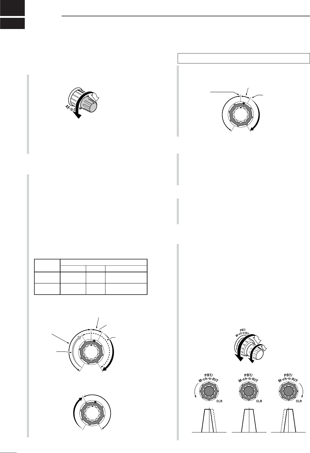
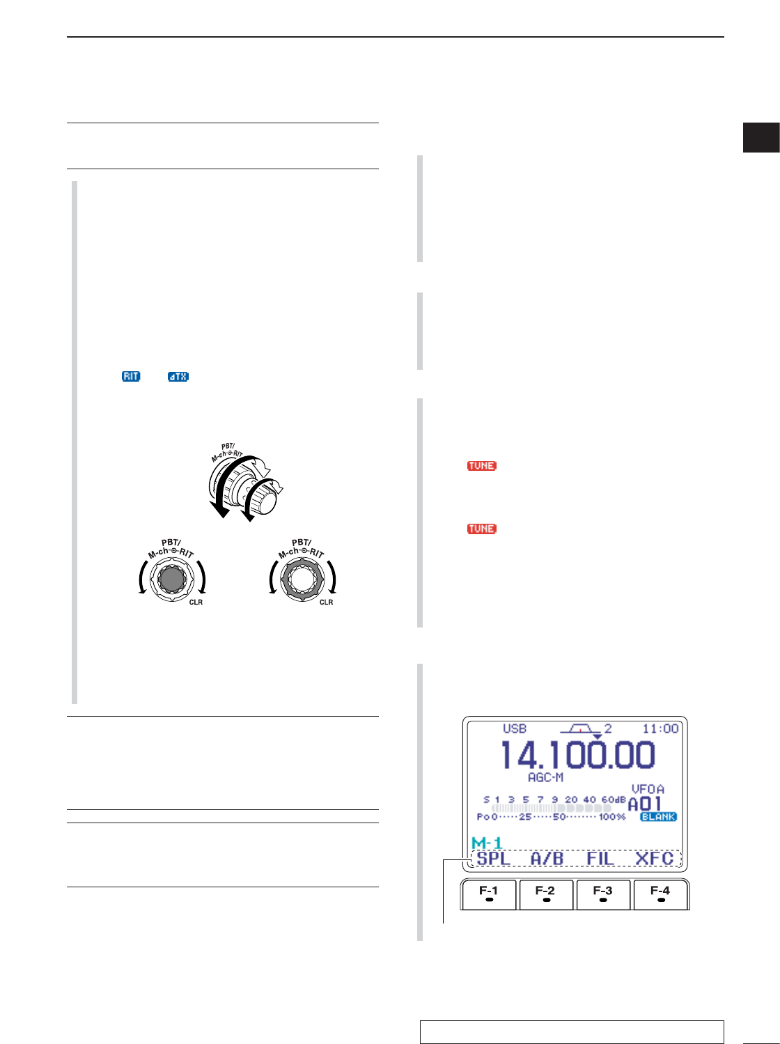
tPASSBAND TUNING/M-ch/RIT CONTROLS
[PBT/M-ch/RIT]
➥Push inner control to toggle the twin Passband
Tuning (PBT) or memory channel/RIT function
ON and OFF.
➥While Twin PBT is selected (p. 79):
●
●
Adjusts the receiver’s DSP filter passband
width.
•Passband width and shift frequency are displayed
on the LCD.
•The default variable range is half of the IF filter
passband width. 25 Hz step is available.
●
●
Push and hold inner control for 1 sec. to return
the PBT to default settings.
Low cutHigh cut Center
+–
PBT1
PBT2
Squelch is
open.
S-meter
squelch
S-meter squelch
threshold
Noise squelch
threshold
(FM/WFM modes)
Lowest threshold Highest threshold
Noise squelch (FM/WFM modes)
Minimum RF gain
Adjustable
range
Maximum RF gain
Recommended level
RF gain
adjustable
range
Maximum
RF gain
S-meter shows
squelch level
Noise squelch (WFM/FM modes)
Squelch is
open.
MODE
SSB, CW
RTTY
AM, FM
WFM
Auto
RF GAIN
SQL
SQL
SET MODE SELECTION
SQL
SQL
RF + SQL
RF + SQL
RF + SQL
Audio outut
decreases
Audio output
increases
1
1
PANEL DESCRIPTION
■Front panel See the illustration of the Front panel on page i-2.
✔
What is the PBT control?
PBT electronically narrows the IF passband width to reject
interference. This transceiver uses DSP to implement PBT.
➥While M-ch/RIT is selected:
●
●
Rotate the inner control to select a memory
channel number (p. 102).
●
●
Push inner control for 1 sec. to turn the
RIT/∂TX mode ON (pgs. 75, 88).
•Push [Z(
MENU
/
GRP
)] to exit the RIT/∂TX mode.
●
●
While the RIT/∂TX mode is OFF:
Rotates outer control to select a memory bank
(p. 106).
●
●
While the RIT/∂TX is ON:
Rotate outer control to shift the receive or
transmit frequency (pgs. 75, 88).
•“ ” or “ ” indicators appear when the RIT or
∂TX function is activate, respectively.
•The shift frequency range is ± 9.999 kHz in 1 Hz
steps (or ±9.99 kHz in 10 Hz steps).
•When the RIT or ∂TX function is ON, push and
hold [F-1 RIT]or [F-2 ∂TX]for 1 sec. to add or
subtract the frequency shift to the display fre-
quency.
✔
What is the RIT function?
RIT (Receiver Incremental Tuning) shifts the receive fre-
quency without shifting the transmit frequency.
This is useful for fine tuning for stations calling you off fre-
quency or when you prefer to listen to slightly different-
sounding voice characteristics, etc.
✔
What is the
∂
TX function?
The ∂TX shifts the transmit frequency without shifting the re-
ceive frequency. This is useful for simple split frequency op-
eration in CW, etc.
yTWIN PBT (M-ch/RIT) INDICATOR
(pgs. 75, 79, 88, 102)
➥Indicates the status of [PBT/M-ch/RIT] (t) acti-
vates as the Twin PBT function or memory chan-
nel/RIT control.
•Indicator is green when the Twin PBT is selected.
•Indicator is off when the M-ch/RIT is selected.
•Indicator is orange when the RIT or ∂TX function is
activate.
uMENU/GROUP KEYS [MENU/GRP] (p. 153)
➥Push either key one or more times to select
menus within a menu group (M,Sor G(Graphic)).
➥Push and hold for 1 sec. to select one of the three
menu groups: M
-
1to M
-
3,S
-
1to S
-
3and G
-
1
(Scope) to G
-
3(SWR meter).
iTUNER/CALL KEY [TUNER/CALL]
➥During HF/50 MHz operation (p. 116):
●
●
Push momentarily to toggle the automatic an-
tenna tuner function ON and OFF.
•An optional antenna tuner must be connected.
• “ ” indicator appears when the tuner is ON.
●
●
Push and hold for 2 sec. to manually tune the
antenna.
•An optional antenna tuner must be connected.
• “ ” indicator appears when the tuner is ON.
➥During 144/430 MHz operation (p. 102):
Push momentarily to select the call channel (or
return to the previous channel/frequency when
the call channel is already selected).
• “C1” is the 144 MHz call channel and “C2” is the 430
MHz call channel.
oMULTI-FUNCTION KEYS [F-1]/[F-2]/[F-3]/[F-4]
➥Push to select the function indicated in the LCD
display above these keys. (pgs. 5–8, 153)
•Functions vary depending on the active menu.
Functions appear
M-ch
RIT
M-ch RIT
Frequency
decreases
Frequency
increases
Channel
decreases
Channel
increases
2
1
PANEL DESCRIPTION
1
See the illustration of the Front panel on page i-2.
3
1PANEL DESCRIPTION
!0 MANUAL NOTCH KEY [MNF/ADJ] (p. 83)
➥Push momentarily to turn the manual notch func-
tion ON and OFF in SSB, CW and AM modes.
• “ ” appears on the display when the function is ac-
tivated.
➥Push and hold for 1 sec. to enter the manual
notch filter set mode.
✔
What is the notch function?
The notch function is a narrow DSP filter that removes inter-
fering tones from CW or AM signals while preserving the de-
sired signal's frequency response.
!1 AUTO NOTCH/VOICE RECORDER KEY
[ANF/•REC]
➥Push momentarily to turn the auto notch function
(ANF) ON and OFF in SSB, AM, FM modes.
(p. 82)
• “ ” appears on the display when the function is ac-
tivated.
➥Push and hold for 1 sec. to record the received
signal’s audio. (p. 95)
!2 SPCH/LOCK KEY [SPCH/LOCK]
➥Push momentarily to have the frequency, etc. an-
nounced by the speech synthesizer. (p. 34)
•The parameters to be announced can be selected in
the miscellaneous (others) set mode. (p. 134)
➥Push and hold for 1 sec. to toggle the dial lock
function ON and OFF. (p. 37)
•The dial lock function electronically locks the main
dial.
• “ ” appears while the dial lock function is activate.
!3 MICROPHONE CONNECTOR (p. 10)
Modular-type microphone connector—Accepts the
supplied microphone (HM-151).
•The optional OPC-589 can be used to connect an 8-pin
microphone such as the SM-20, if desired.
•A microphone connector is also available on the rear
panel. DO NOT connect 2 microphones simultaneously.
!4
UP/DOWN (BAND) KEYS
[Y(
BAND
)]/[Z(
BAND
)]
➥Push momentarily to select a frequency band or
TV channel.
➥Push and hold
[Y(
BAND
)]
for 1 sec. to toggle the
simple band scope display ON and OFF.
➥Push and hold
[Z(
BAND
)]
for 1 sec. to toggle the
multi-function meter display ON and OFF.
!5 MAIN DIAL TENSION LATCH
Selects the main dial drag.
•Three positions are available. Upper setting turns on
clicks as the dial is turned..
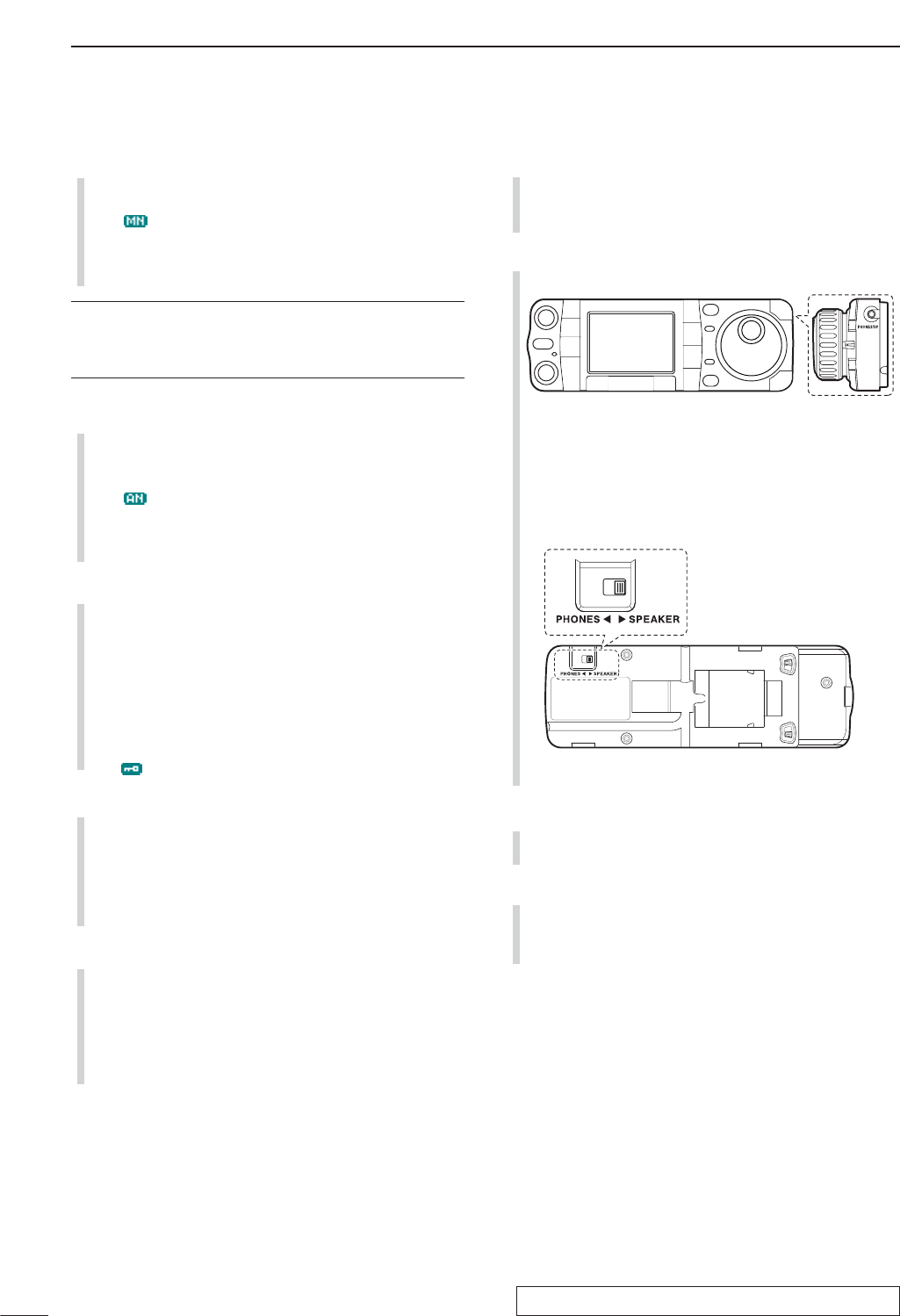
!6 HEADPHONE JACK [PHONES] (p. 18)
Accepts headphones with 8–16 impedance.
•When headphones are connected, no receive audio
comes from the speaker.
•When the PHONES/SPEAKER switch on the back of the
front panel is set to the [SPEAKER] position, an external
speaker can be used instead of headphones. This is
convenient for mobile or outdoor operation.
!7 MAIN DIAL [DIAL]
Changes the displayed frequency and selects val-
ues for selected set mode items, etc.
!8 RECEIVE/TRANSMIT INDICATORS [RX]/[TX]
➥[RX]: Lights green in receive mode and when
squelch is open.
➥[TX]: Lights red while transmitting.
Back of the front panel
See the illustration of the Front panel on page i-2.
4
1
PANEL DESCRIPTION
1
!9 TUNING STEP KEY [TS] (pgs. 30–32)
➥While in SSB/CW/RTTY modes, push momentar-
ily to turn the programmable tuning step ON and
OFF. While in AM/FM/WFM modes, push mo-
mentarily to toggle the programmable tuning step
and 1 MHz quick tuning step.
•While the programmable tuning step indicator is dis-
played, the frequency can be changed in programmed
kHz steps.
•0.01 (AM/FM/WFM mode only), 0.1, 1, 5, 9, 10, 12.5,
20, 25 and 100 kHz tuning steps are available.
•A MHz quick tuning step is only available in AM, FM
and WFM modes.
➥While programmable tuning steps are OFF, turns
the 1 Hz step ON and OFF when pushed and
held for 1 sec.
•1 and 10 Hz steps are only available in SSB, CW and
RTTY modes.
•1 Hz indication appears, and the frequency can be
changed in 1 Hz steps.
➥While the programmable tuning step is ON, en-
ters the tuning step selection mode when pushed
and held for 1 sec.
@0 NOISE BLANKER KEY [NB/ADJ] (p. 80)
➥Push momentarily to turn the noise blanker ON
and OFF. The noise blanker reduces pulse-type
noise such as that generated by automobile igni-
tion systems. This function does not work on non-
pulse noise or in WFM mode.
• “ ” appears when the noise blanker is ON.
➥Push and hold for 1 sec. to enter the noise
blanker set mode.
@1 NOISE REDUCTION KEY [NR/LEV] (p. 81)
➥Push momentarily to turn DSP noise reduction
ON and OFF.
• “ ” appears on the display when the function is ac-
tivated.
➥Push and hold for 1 sec. to enter the DSP noise
reduction level.
@2 FUNCTION DISPLAY
Shows the operating frequency, function key menus,
simple band scope display, selected memory chan-
nel, receiving TV channel, etc. See p. 13 for details.
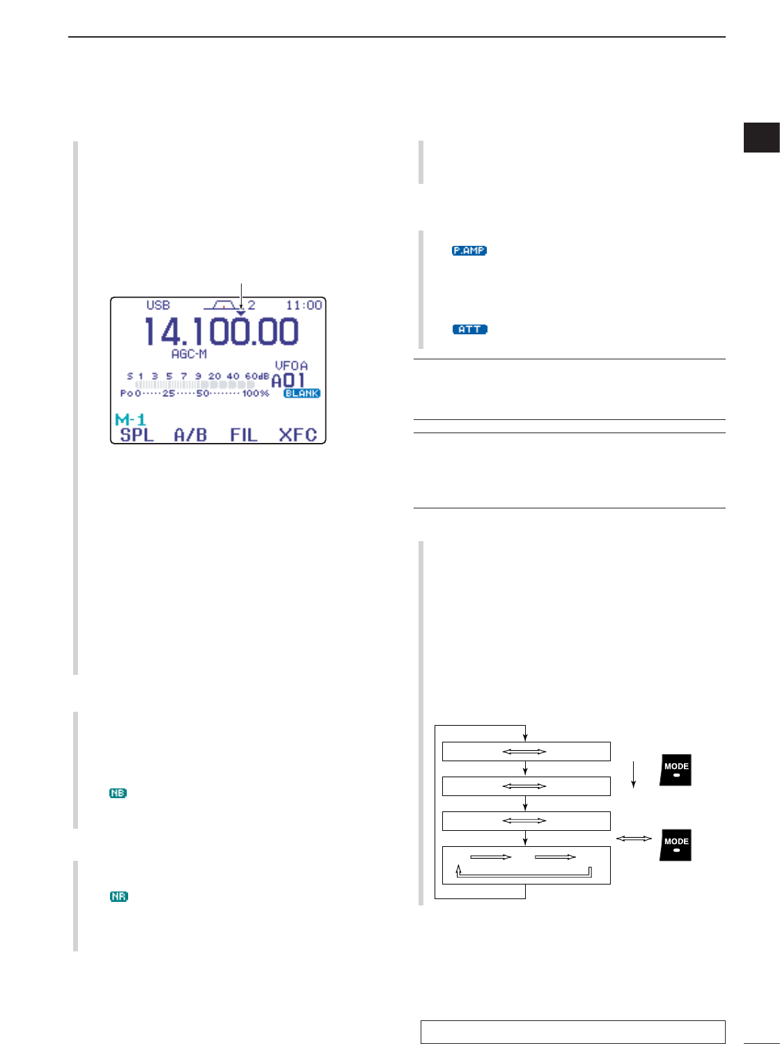
@3 PRE AMP/ATTENUATOR KEY [P.AMP/ATT]
(p. 74)
➥Push momentarily to turn the preamp ON or OFF.
•“ ” indicator appears when the preamp is acti-
vated.
➥Push and hold for 1 sec. to turn the 12 dB attenu-
ator ON; push momentarily to turn the attenuator
OFF.
• “ ” indicator appears when the attenuator is ac-
tivated.
✔
What is the preamp?
The preamp amplifies signals in the receiver front end (input)
circuit to improve the S/N ratio and sensitivity. Turn ON
‘P.AMP’ when receiving weak signals.
✔
What is the attenuator?
The attenuator prevents a strong undesired signal near the
desired frequency or near your location, such as from a
broadcast station, from causing distortion or spurious sig-
nals.
@4 MODE KEY [MODE] (p. 34)
➥Push momentarily to cycle through the operating
modes:
USB/LSB ➧CW/CW-R ➧
RTTY/RTTY-R ➧AM/FM/WFM
➥Push and hold for 1 sec. to toggle the following
operating modes:
USB ↔LSB
CW ↔CW-R
RTTY ↔RTTY-R
AM →FM →WFM →AM, etc
OPERATING MODE SELECTION
Push
momentarily
Push and hold
for 1 sec.
USB LSB
AM FM WFM
CW CW-R
RTTY-R
RTTY
Programmable tuning step indicator
See the illustration of the Front panel on page i-2.
5
1PANEL DESCRIPTION
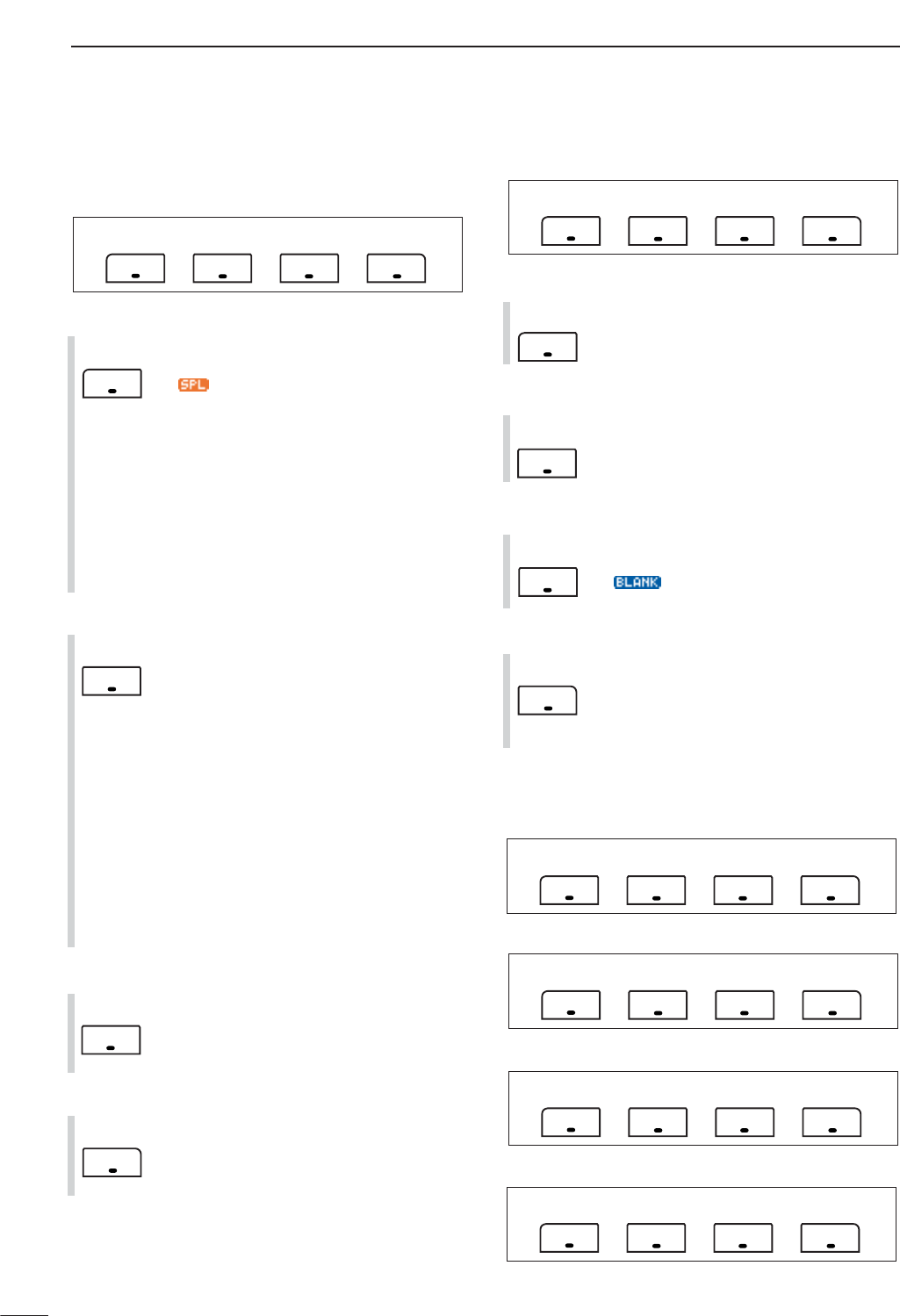
■Multi-function keys
DMenu M-1 functions
SPLIT OPERATION
➥Push momentarily to toggle the split func-
tion ON and OFF. (p. 91)
•“”and transmit frequency appear when
the split function is ON.
➥Push and hold for 1 sec. to turn the quick
split function ON. (p. 92)
•The offset frequency must be programmed in
advance using the miscellaneous (others) set
mode. (p. 131)
•The offset frequency is shifted from the dis-
played frequency.
•The quick split function can be turned OFF in
the miscellaneous (others) set mode. (p. 131)
VFO A/B SELECTION
➥Push momentarily to exchange the trans-
mit VFO and receive VFO contents. (p.
27)
➥Push momentarily to toggle the transmis-
sion VFO and reception VFO during split
operation. (p. 91)
➥Push momentarily to toggle the transmit
and receive frequencies (and modes) of
memory channels when the split function
is turned ON.
➥Push and hold for 1 sec. to equalize the
frequency and operating mode of the two
VFO’s.
•The lower indicated frequency and operating
mode are equalized to the upper (indicated)
VFO frequency and operating mode.
FILTER SELECTION (p. 77)
➥Push momentarily to select one of three
IF filter settings.
➥Push and hold for 1 sec. to enter the filter
set mode.
TRANSMIT FREQUENCY CHECK (pgs. 65, 91)
Monitors the transmit frequency when
pushed and held.
•While pushing this key, the transmit fre-
quency can be changed with [DIAL].
DMenu M-2 functions
MEMORY MENU (p. 105)
Push momentarily to indicate the memory
frequency and modes.
•Memory list indication is available.
MEMORY WRITE (pgs. 103, 104)
Push and hold for 1 sec. to store the se-
lected readout frequency and operating
mode into the displayed memory channel.
MEMORY CLEAR (p. 108)
Push and hold for 1 sec. to clear the se-
lected memory channel contents.
• “ ” appears.
VFO/MEMORY SELECTION
➥Push momentarily to toggle VFO and
memory modes. (pgs. 27, 102)
➥Push and hold for 1 sec. to transfer the
selected memory channel to the currently
displayed VFO. (p. 109)
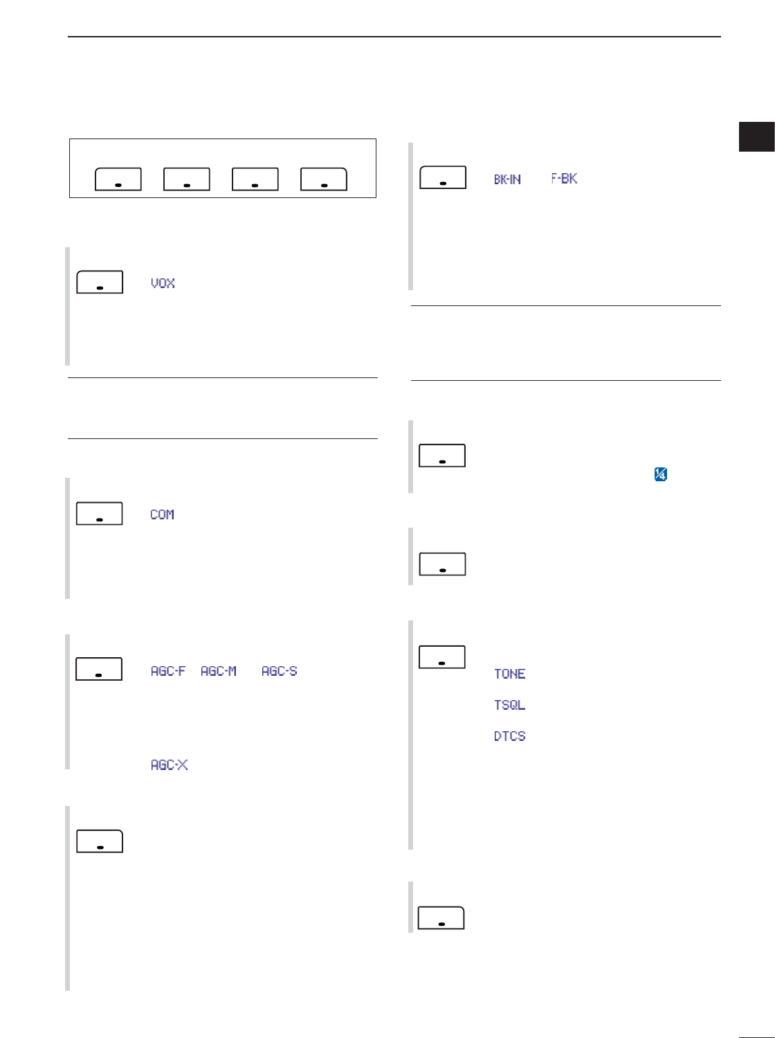
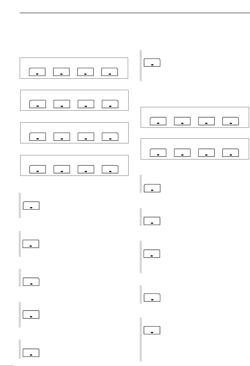
DMenu M-3 functions
DURING SSB OPERATION:
DURING CW OPERATION:
DURING RTTY OPERATION:
DURING AM OPERATION:
F-1 F-2 F-3 F-4
VOX AGC
F-1 F-2 F-3 F-4
1/4 AGC
F-1 F-2 F-3 F-4
1/4BRK AGC
F-1 F-2 F-3 F-4
TBWVOX COM AGC
F-4
V/M
F-3
MCL
F-2
MW
F-1
MEM
F-1 F-2 F-3 F-4
MWMEM V/M
MCL
F-4
XFC
F-3
FIL
F-2
A/B
F-1
SPL
SPL A/B FIL XFC
F-1 F-2 F-3 F-4
6
1
PANEL DESCRIPTION
1
DURING FM/WFM OPERATIONS:
VOX FUNCTION(p. 85)
➥Push momentarily to toggle the VOX func-
tion ON and OFF.
•“ ” appears when the VOX function is
ON.
➥Push and hold for 1 sec. to enter the VOX
set mode.
•The VOX gain, ANTI-VOX, VOX delay and
VOX gain can be set in VOX set mode.
✔
What is the VOX function?
The VOX function (voice operated transmission) activates
the transmitter when you speak into the microphone; then,
automatically returns to receive when you stop speaking.
SPEECH COMPRESSOR (p. 89)
➥Push momentarily to toggle the speech
compressor ON and OFF.
•“ ” appears when the speech compres-
sor is ON.
➥Push and hold for 1 sec. to enter the com-
pression level set mode.
•Speech compression can be adjusted in
compression level set mode.
AGC(p. 76)
➥Push to change the time constant of the
AGC circuit.
• “ ,” “ ” or “ ” appears when
the fast time constant, middle time constant
or slow time constant is selected, respec-
tively.
➥Push and hold for 1 sec. to enter the AGC
set mode.
• “ ” (OFF) can be selected.
TBW (p. 86)
➥Push momentarily to indicate the selected
TX filter width.
• The popup indicator appears.
➥Push and hold for 1 sec. to toggle the TX
filter width between narrow, middle or
wide.
•The following filters are specified as the de-
fault. Each filter width can be set in the quick
set mode. (pgs. 123, 124)
WIDE : 100 Hz to 2900 Hz
MID : 300 Hz to 2700 Hz
NAR : 500 Hz to 2500 Hz
BREAK-IN FUNCTION (p. 87)
➥Push momentarily to select semi-break-in,
full break-in (QSK) and break-in OFF.
•“ ” or “ ” appears when selecting
semi break-in or full break-in, respectively.
•An external switch, such as a foot switch,
must be connected to the ACC socket (pin 3,
pin 7 or RTTY SEND—see p. 23) if break-in
is turned OFF.
➥Push and hold for 1 sec. to enter the
break-in delay time set mode.
✔
What is the break-in function?
Full break-in (QSK) activates the receiver between transmit-
ted dots and dashes. This is useful when operating in nets,
or during DX pile-ups and during contests, when “fast re-
sponses” are common.
1/4 FUNCTION
Push to toggle the 1/4-speed tuning func-
tion ON and OFF in CW and RTTY
modes.
•When the 1⁄4function is ON, “ ” appears
and fine tuning can be used.
DUPLEX FUNCTION (p. 63)
➥Push to select the duplex transmit offset
direction or turn the function OFF.
➥Push and hold for 1 sec. to turn the one-
touch repeater function ON/OFF.
FM TONE OPERATION
➥Push momentarily to set the subaudible
tone encoder for repeater use, tone
squelch function, DTCS and OFF.
•“ ” appears when the repeater tone
function is ON. (p. 63)
• “ ” appears when the tone squelch func-
tion is ON. (p. 60)
•“ ” appears when the DTCS squelch
function is ON. (p. 62)
➥Push and hold for 1 sec. to enter the tone
frequency or DTCS code set mode. (pgs.
60, 62)
•Tone scan function is also available. (p. 61)
➥Push and hold to transmit a 1750 Hz tone
when pushing and holding [PTT]. (p. 67)
9600 MODE
Push to turn the 9600 bps data transmis-
sion mode ON and OFF. (p. 118)
F-4
9600
F-3
TON
F-2
DUP
F-2
1/4
F-1
BRK
F-4
TBW
F-3
AGC
F-2
COM
F-1
VOX
F-1 F-2 F-3 F-4
VOX DUP TON
9600
7
1PANEL DESCRIPTION
DMenu S-1 functions
DURING SSB/AM OPERATION:
DURING CW OPERATION:
DURING RTTY OPERATION:
DURING FM/WFM OPERATIONS:
VO (p. 95)
Push to enter the voice recorder mode.
•The voice TX/RX menu or voice root menu
appears depending on the “VOICE 1st
Menu” setting in the miscellaneous (others)
set mode. (p. 136)
METER SELECTION(p. 36)
Push to select the type of metering dis-
played (during transmit) on the display.
•Power, SWR, ALC or COMP metering can be
selected.
•Only an S-meter is available during receive.
VOICE SQUELCH CONTROL (p. 84)
Push to toggle the voice squelch control
function ON and OFF.
KEYER OPERATION (p. 45)
Push to enter the memory keyer mode.
•The keyer send menu or keyer root menu ap-
pears depending on the “KEYER 1st
Menu” setting in the miscellaneous (others)
set mode.(p. 136)
RTTY DECODER FUNCTION (p. 54)
Push to toggle the RTTY decoder display
ON and OFF.
•RTTY decoder screen appears.
DTMF OPERATION
Push to enter DTMF memory mode.
(p. 67)
•The DTMF send menu or DTMF root menu
appears depending on the “DTMF 1st
Menu” setting in the miscellaneous (others)
set mode. (p. 136)
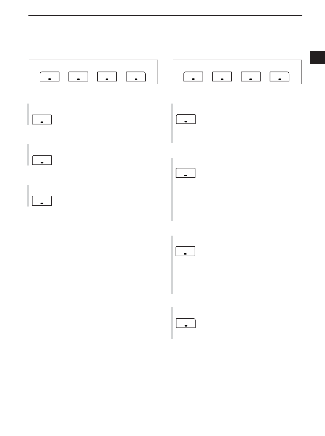
DMenu S-2 functions
DURING VFO MODE:
DURING MEMORY MODE:
SCAN(pgs. 113–115)
➥Push momentarily to start or stop the
scan function.
PRIORITY WATCH (p. 115)
Push to start or stop priority watch.
VFO/MEMORY SELECTION
➥Push momentarily to toggle VFO and
memory modes. (pgs. 27, 102)
➥Push and hold for 1 sec. to transfer the
frequency and operating mode in the se-
lected memory channel to the currently
displayed VFO. (p. 109)
VOICE SQUELCH CONTROL (p. 84)
Push to toggle the voice squelch control
function ON and OFF.
SELECT SCAN
➥Push momentarily to toggle the select
scan settings ON and OFF for the se-
lected memory channel. (pgs. 106, 115)
➥Push and hold for 2 sec. to clear all select
scan setting. (p. 115)
➥While scanning, push to toggle the se-
lected memory scan ON and OFF.
(p. 115)
F-2
SEL
F-4
VSC
F-3
V/M
F-2
PRI
F-1
SCN
F-1 F-2 F-3 F-4
VSCSCN SEL V/M
F-1 F-2 F-3 F-4
VSCSCN PRI V/M
F-4
DTM
F-2
DEC
F-2
KEY
F-4
VSC
F-3
MET
F-1
VO
F-1 F-2 F-3 F-4
VSCVO DTM MET
F-1 F-2 F-3 F-4
VSCVO DEC MET
F-1 F-2 F-3 F-4
VSCVO KEY MET
F-1 F-2 F-3 F-4
VSCVO MET
8
1
PANEL DESCRIPTION
1
DMenu S-3 functions
MEMORY WRITE (pgs. 103, 104)
Push and hold for 1 sec. to store the dis-
played VFO frequency and operating
mode into the selected memory channel.
MEMO PAD WRITE (p. 111)
Push to store the displayed VFO fre-
quency and operating mode into a memo
pad.
MEMO PAD READ(p. 112)
Push to call up a memo pad.
✔
What is the memo pad function?
The memo pad function stores the frequency and operating
mode for easy recall. The memo pads are separate from the
usual memory channels. The default number of memo pads
is 5, however, this can be increased to 10 in the miscella-
neous (others) set mode, if desired. (p. 134)
DMenu G-1 (Scope) functions
SWEEP STEPS (pgs. 72, 73)
➥Push momentarily to change the sweep
step size.
•Available steps are ±10, 25, 50, 100 and 250
kHz.
➥Push and hold for 1 sec. to change the
sweep steps to ±10 kHz.
PEAK HOLD (pgs. 72, 73)
➥Push to freeze the current simple band
scope display.
•“H” indicator appears while the function is in
use.
➥Push and hold for 1 sec. to clear the peak
levels.
•Peak levels are displayed in the background
on the simple band scope display. The peak
hold function can be disabled in the scope
set mode. (p. 73)
FIX/CENTER SELECTION (pgs. 72, 73)
➥Push to toggle the simple band scope fix
mode and center mode.
•Fix mode:
Rotating [DIAL] leaves the marker centered.
•Center mode:
Rotating [DIAL] moves the edge frequencies.
➥While fix mode operation, push and hold
for 1 sec. to set the displayed frequency
to that of the marker.
SWEEP SPEED
➥Push momentarily to change the sweep
speed between Fast and Slow. (pgs. 72,
73)
➥Push and hold for 1 sec. to enter the
scope set mode. (p. 73)
F-4
SPD
F-3
FIX
F-2
HLD
F-1
SPN
F-1 F-2 F-3 F-4
SPN HLD FIX SPD
F-3
MPR
F-2
MPW
F-1
MW
F-1 F-2 F-3 F-4
MW MPW MPR

9
1PANEL DESCRIPTION
zSPCH/LOCK KEY [SPCH/LOCK]
➥Push momentarily to have the frequency, etc. an-
nounced by the speech synthesizer. (p. 34)
•The parameters to be announced can be selected in
the miscellaneous (others) set mode. (p. 134)
➥Push and hold for 1 sec. to toggle the microphone
lock function ON and OFF. (p. 37)
xPTT SWITCH [PTT] (p. 37)
Push and hold to transmit; release to receive.
cUP/DOWN SWITCHES [Y]/[Z]
Change the operating frequency.
•Push and hold to change the frequency repeatedly.
•Tuning step size is 50 Hz if no TS indicator is displayed.
vTRANSMIT INDICATOR
Lights red while transmitting.
bKEYPAD
➥Pushing a key selects the operating band.
•[(GENE)•] selects the general coverage band.
➥Pushing the same key 2 or 3 times calls up other
stacked frequencies in the band. (p. 28)
•Icom’s triple band stacking register memorizes 3 fre-
quencies in each band.
➥After pushing [(F-INP)ENT], enter a numeric fre-
quency, followed by pressing [(F-INP)ENT]
again. (p. 29)
•e.g. to enter 14.195 MHz, push [(F-INP)ENT] [1] [4]
[•] [1] [9] [5] [(F-INP)ENT].
nFILTER SELECTION [FIL] (p. 77)
➥Push momentarily to select one of three IF filter
settings.
➥Push and hold for 1 sec. to enter the filter set
mode.
mMODE KEY [MODE] (p. 34)
➥Push momentarily to cycle through the operating
modes:
USB/LSB ➧CW/CW-R ➧
RTTY/RTTY-R ➧AM/FM/WFM
➥Push and hold for 1 sec. to toggle the following
operating modes:
USB ↔LSB
CW ↔CW-R
RTTY ↔RTTY-R
AM →FM →WFM →AM, etc
,POWER INDICATOR
Lights green while transceiver power is ON.
.PROGRAMMABLE FUNCTION KEYS [F-1]/[F-2]
Program and perform a selected function.
•The functions can be assigned in the miscellaneous (oth-
ers) set mode (p. 135). The default settings for [F-1] and
[F-2] are “MPW” and “MPR,” respectively.
⁄0 MEMORY WRITE [MW] (pgs. 103, 104)
Push and hold for 1 sec. to store the displayed VFO
frequency and operating mode into the displayed
memory channel.
⁄1 VFO/MEMORY SELECTION [V/M]
➥Push momentarily to toggle VFO and memory
modes. (pgs. 27, 102)
➥Push and hold for 1 sec. to transfer the selected
memory channel to the currently displayed VFO.
(p. 109)
⁄2 TRANSMIT FREQUENCY CHECK [XFC]
(pgs. 65, 91)
Monitors the transmit frequency when pushed and
held.
•While pushing this key, the transmit frequency can be
changed with [DIAL].
⁄3 TUNER/CALL KEY [TUNER/CALL]
➥During HF/50 MHz operation (p. 116):
●
●
Push momentarily to toggle the automatic an-
tenna tuner function ON and OFF.
•An optional antenna tuner must be connected.
• “ ” indicator appears when the tuner is ON.
●
●
Push and hold for 2 sec. to manually tune the
antenna.
•An optional antenna tuner must be connected.
• “ ” indicator appears when the tuner is ON.
➥During 144/430 MHz operation (p. 103):
Push momentarily to select the call channel (or
return to the previous channel/frequency when
the call channel is already selected).
• “C1” is the 144 MHz call channel and “C2” is the 430
MHz call channel.
■Microphone (HM-151)
Default settings
[F-1] (MPW): Push to store the selected readout
frequency and operating mode into
a memo pad.
[F-2] (MPR): Push to call up a memo pad.
See the illustration of the HM-151 on page i-2.
10
1
PANEL DESCRIPTION
1
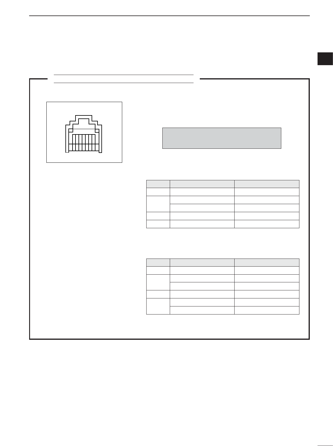
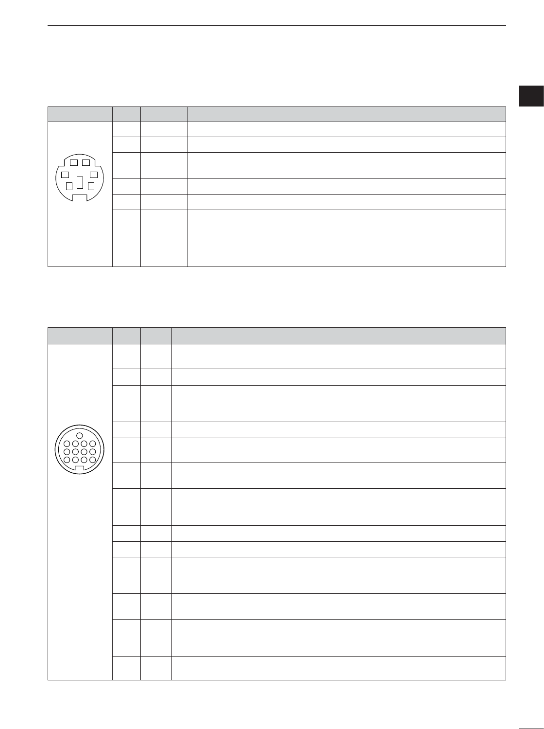
MICROPHONE CONNECTOR INFORMATION
r PTT
y Microphone input
w Frequency up/down
u GND
q +8 V DC output
i DATA IN
t GND (Microphone ground)
e M8V SW
r PTT
y Microphone input
w Frequency up/down
u GND
q +8 V DC output
i Squelch switch
t GND (Microphone ground)
e M8V SW
Rear panel view
12345678
HM-151
HM-103
CAUTION:DO NOT short pin 1 to ground as
this can damage the internal 8 V regulator.
PIN NO. FUNCTION DESCRIPTION
1
• When HM-151 is connected
• When HM-103 is connected
3
8
+8 V DC output Max. 10 mA
2Frequency up Ground
Frequency down Ground through 470
HM-151 connection Goes to ground to connect
3HM-151 connection Open to pin 8 as SQL
HM-151 data Control signal input
PIN NO. FUNCTION DESCRIPTION
1+8 V DC output Max. 10 mA
2Frequency up Ground
Frequency down Ground through 470
8Squelch open “LOW” level
Squelch closed “HIGH” level
DMicrophone connector
11
1PANEL DESCRIPTION
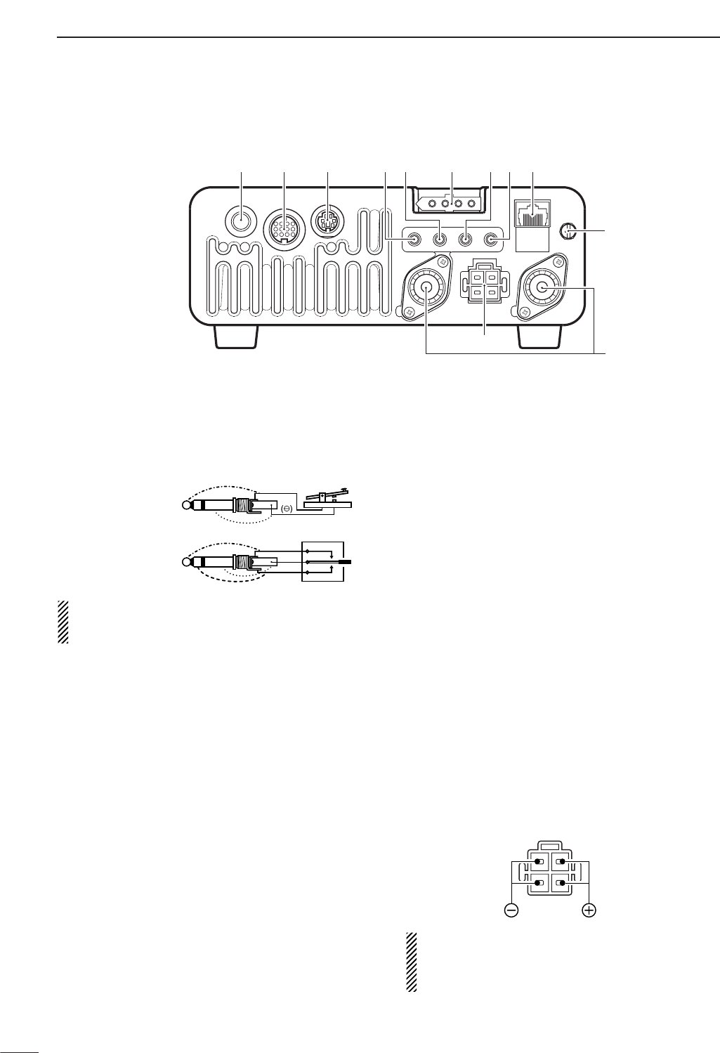
qELECTRONIC KEYER JACK [KEY] (p. 22)
Accepts a paddle to activate the internal electronic
keyer.
•Selection between the internal electronic keyer and
straight key operation can be made in the keyer set
mode. (p. 50)
If you use an external electronic keyer, make sure
the output voltage of the keyer is less than 0.4 V
when keying the transmitter.
wACCESSORY SOCKET [ACC] (p. 12)
Enables connection to external equipment such as a
TNC for data communications, a linear amplifier or
an automatic antenna selector/tuner, etc.
•See page at right for socket wiring information.
eDATA SOCKET [DATA] (p. 12)
6-pin mini-DIN socket to connect a TNC (Terminal
Node Controller), etc. for packet operation.
•See page at right for socket wiring information.
rVIDEO OUT JACK [VOUT] (p. 18)
Outputs a video signal.
tCI-V REMOTE CONTROL JACK [REMOTE]
(p. 144)
➥Designed for use with a personal computer for re-
mote control of the transceiver functions.
➥Used for transceiver operation with another Icom
CI-V transceiver or receiver.
yTUNER CONTROL SOCKET [TUNER] (p. 20)
Accepts the control cable from an optional AH-4
HF
/50
MH
z
AUTOMATIC ANTENNA TUNER
.
uRTTY JACK [RTTY] (p. 23)
Connects an external terminal unit for RTTY (FSK)
operation.
•The keying polarity, mark/shift frequencies and etc. can
be selected in quick set mode (p. 125).
iEXTERNAL SPEAKER JACK [EXT SP] (p. 18)
Accepts a 4–8 speaker.
oMICROPHONE CONNECTOR [MIC] (p. 17)
Accepts the supplied microphone (connected in par-
allel with the front panel’s [MIC] connector).
•See p. 2 for microphone notes.
•See p. 10 for microphone connector information.
!0 GROUND TERMINAL [GND] (p. 15)
Connect this terminal to a station or vehicle ground
to prevent electrical shocks, TVI, BCI and other
problems.
!1 ANTENNA CONNECTOR [ANT1], [ANT2] (p. 17)
Accepts a 50 antenna with a PL-259 connector.
•[ANT1] is for connection to an HF/50 MHz antenna.
•[ANT2] is for connection to an 144/430 MHz antenna.
•ANT1 is used below and ANT2 above 60 MHz.
!2 DC POWER SOCKET [DC13.8V] (p. 19)
Accepts 13.8 V DC through the supplied DC power
cable.
NOTE: DO NOT use a cigarette lighter socket as a
power source when operating in a vehicle. The plug
may cause voltage drops and ignition noise may be
superimposed onto transmit or receive audio.
Rear panel view
When connecting
a straight key
When connecting
a paddle
(dot)
(com)
(dash)
()
KEY ACC DATA MIC
ANT2 ANT1
DC 13.8V
GND
qwe yuirto
!0
!1
!2
■Rear panel
12
1
PANEL DESCRIPTION
1
ACC
PIN No.
NAME DESCRIPTION SPECIFICATIONS
1234
8765
9
10 11 12
13
Rear panel view
qbrown igray
wred owhite
eorange !0 black
ryellow !1 pink
tgreen !2 light
blue
yblue
upurple !3 light
green
1 8 V Regulated 8 V output. Output voltage : 8 V ±0.3 V
Output current : Less than 10 mA
2 GND Connects to ground. ———
Input/output pin. (HF/50 MHz only) Ground level : –0.5 V to 0.8 V
3
HSEND
Goes to ground when transmitting. Output current : Less than 20 mA
Grounded when transmits. Input current (Tx) : Less than 200 mA
4 BDT Data line for the optional AT-180. ———
5 BAND Band voltage output. Output voltage : 0 to 8.0 V
(Varies with amateur band)
6 ALC ALC voltage input. Control voltage : –4 V to 0 V
Input impedance : More than 10 k
Input/output pin. (144/430 MHz only) Ground level : –0.5 V to 0.8 V
7
VSEND
Goes to ground when transmitting. Output current : Less than 20 mA
Grounded when transmits. Input current (Tx) : Less than 200 mA
8 13.8 V 13.8 V output when power is ON. Output current : Max. 1 A
9 TKEY Key line for the optional AT-180. ———
“High” level : More than 2.4 V
10 FSKK Controls RTTY keying “Low” level : Less than 0.6 V
Output current : Less than 2 mA
11 MOD Modulator input. Input impedance : 10 k
Input level : Approx. 100 mV rms
AF detector output. Output impedance : 4.7 k
12 AF Fixed level, regardless of [AF] Output level : 100–300 mV rms
position in
default settings.
13 SQLS Squelch output. SQL open : Less than 0.3 V/5 mA
Grounded when squelch opens. SQL closed : More than 6.0 V/100 µA
DATA
PIN No.
NAME DESCRIPTION
12
34
56
Rear panel view
1 DATA IN Input terminal for data transmit. (1200 bps: AFSK/9600 bps: G3RUH, GMSK)
2 GND Common ground for DATA IN, DATA OUT and AF OUT.
3 PTT P PTT terminal for packet operation. Connect to ground to activate the transmitter.
When grounded, microphone input (pin 6) of [MIC] connector will be disconnected.
4 DATA OUT Data out terminal for 9600 bps operation only.
5 AF OUT Data out terminal for 1200 bps operation only.
Squelch out terminal. Becomes ground level when the transceiver receives a signal
which opens the squelch.
6SQL •To avoid interfering transmissions, connect squelch to the TNC to inhibit transmission
when squelch is open.
• Keep RF gain at a normal level, otherwise a “SQL
”
signal will not be output.
Color refers to the cable strands of the supplied cable.
DDATA socket
DACC socket
13
1PANEL DESCRIPTION
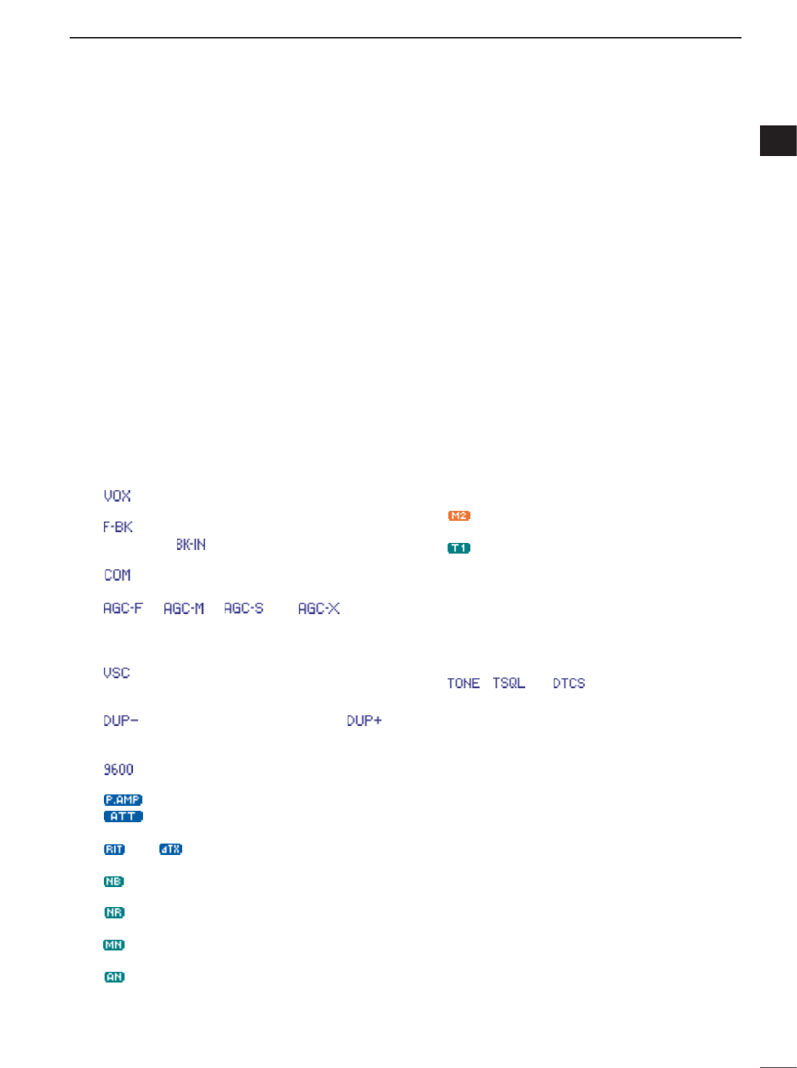
qFREQUENCY READOUT
Shows the operating frequency.
wMETER READOUTS
➥Shows received signal strength while receiving.
➥Shows either transmit power meter (Po), SWR,
ALC or compression level meter (COM) while
transmitting.
eMULTI-FUNCTION KEY GUIDE
Indicates the function of the multi-function keys.
These alphanumeric readouts show a variety of in-
formation such as current functions of the “F” keys
[F-1] to [F-4].
rSPLIT FREQUENCY READOUT
Shows the transmit frequency during split operation.
tBLANK MEMORY INDICATOR
Appears when the displayed memory channel is not
programmed (blank channel).
• This indicator appears both in VFO and memory modes.
yMEMORY CHANNEL READOUT
Shows the selected memory channel or scan edge
channel.
•Memory bank indicator (A to E) appears to the left of
memory channel.
• This indicator appears both in VFO and memory modes.
uVFO/MEMORY INDICATORS
➥VFO A or B appears when VFO mode is selected;
MEMO appears when memory mode is selected.
iVOICE RECODER INDICATORS
REC appears when the digital voice recoder func-
tion is activated.
oLOCK INDICATOR
Appears when the dial lock function is activated.
!0 DIRECT FREQUENCY ENTRY INDICATOR (p. 29)
Appears when the transceiver is ready for direct fre-
quency entry.
•This indicator appears when [(F-INP)ENT] key on the
HM-151 is pushed.
!0!2 !1 @4 @2
!5a
o
t
u
y!9
@0
!5b
!8
!3!4 @3
r
i@1
e
w
q
!6
!7
■Function display
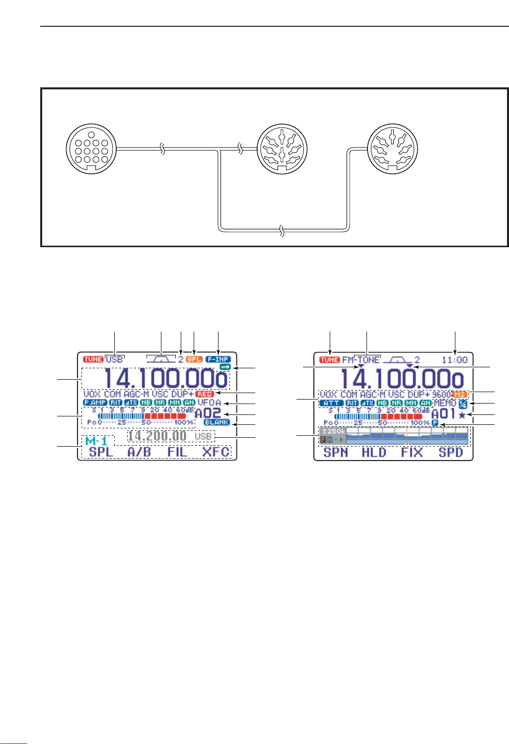
ACC 1 ACC 2
q FSKK t AF
w GND y SQLS
e HSEND u 13.8 V
r MOD i ALC
q 8 V t ALC
w GND y VSEND
e HSEND u 13.8 V
r BAND
1234
88
765
9
10 11 12
13
1
2
3
4
7
6
5
1
2
3
4
7
6
5
Connect to ACC socket
• When connecting the ACC conversion cable (OPC-599)
14
1
PANEL DESCRIPTION
1
!1 SPLIT INDICATOR
Appears during split opeation.
!2 IF FILTER INDICATOR (p. 77)
Shows the selected IF filter number.
!3 PASSBAND WIDTH INDICATOR(p. 77, 79)
Graphically displays the passband width for twin
PBT operation and center frequency for IF shift op-
eration.
!4 MODE INDICATORS
Shows the selected operating mode.
• “-R” appears when CW reverse or RTTY reverse mode
is selected.
!5 PROGRAMMABLE/1 MHz TUNING STEP
INDICATORS
➥!5a appears when the 1 MHz quick tuning step is
selected.
➥!5b appears when the programmable tuning step
is selected.
!6 FUNCTION INDICATORS
➥“ ” appears when the VOX function is acti-
vated.
➥“ ” appears when full break-in operation is se-
lected and “ ” appears when semi break-in
operation is selected.
➥“ ” appears when the speech compressor is
activated.
➥“ ,” “ ,” “ ” or “ ” (OFF)
appears when the fast time constant, middle time
constant, slow time constant or AGC OFF is se-
lected, respectively.
➥“”appears when the VSC (Voice Squelch
Control) function is activated in phone (SSB, AM,
FM, WFM) modes.
➥“ ” appears for negative offset and “ ”
appears for positive offset during duplex opera-
tion.
➥“”appears when the 9600 mode is activated
for packet operation.
➥“ ” appears when the preamp is ON,
“”appears when the 12 dB attenuator is
ON.
➥“ ” or “ ” appears when the RIT or ∂TX
function is activated.
➥“ ” appears when the noise blanker is acti-
vated.
➥“”appears when DSP noise reduction is acti-
vated.
➥“” appears when the manual notch function is
activated.
➥“”appears when the automatic notch function
is activated.
!7 MULTI-FUNCTION SCREEN
Shows the screens for the multi-function meter, sim-
ple band scope, SWR meter, memory channel,
voice recorder, memory keyer, DTMF memory en-
coder, RTTY decoder, IF filter selection or popup in-
dication, etc.
!8 PRIORITY WATCH INDICATOR
Appears while priority scan is activated.
!9 SELECT MEMORY CHANNEL INDICATOR
Appears when select scan is enabled for the se-
lected memory channel.
@0 1/4 FUNCTION INDICATOR
Appears when the 1⁄4-speed tuning function is acti-
vated in CW and RTTY modes.
@1 EXTERNAL KEYPAD INDICATOR
Shows the memory keyer or voice memory channel
number. This indication appears when “External
Keypad (VOICE)” or “External Keypad
(KEYER)” in the miscellaneous (others) set mode
(p. 137) is set to ON, and which one is activated.
<Example>
•“”appears when the memory keyer “M2” is trans-
mitted.
•“”appears when the voice memory “T1” is transmit-
ted.
@2 CLOCK READOUT
Shows the current time.
•UTC time or local time can be selected.
@3 TONE INDICATOR
Appears during FM tone operation.
•“ ,” “ ” or “ ” appears when the repeater
tone, tone squelch, DTCS squelch are activated, re-
spectively.
@4 TUNER INDICATOR
Appears when the optional automatic antenna tuner
is activated.
•This indicator blinks while the tuner is tuning..
2
15
INSTALLATION AND CONNECTIONS
■Unpacking
After unpacking, immediately report any damage to the
delivering carrier or dealer. Keep the shipping cartons.
For a description and a diagram of accessory equip-
ment included with the IC-7000, see ‘Supplied acces-
sories’ on p. i-1 of this manual.
■Selecting a location
Select a location for the transceiver that allows ade-
quate air circulation, free from extreme heat, cold, or
vibrations, and away from TV sets, TV antenna ele-
ments, radios and other electromagnetic sources.
The base of the transceiver has an adjustable stand
for desktop use. Set the stand to one of two angles de-
pending on your operating conditions. (see description
on right hand page)
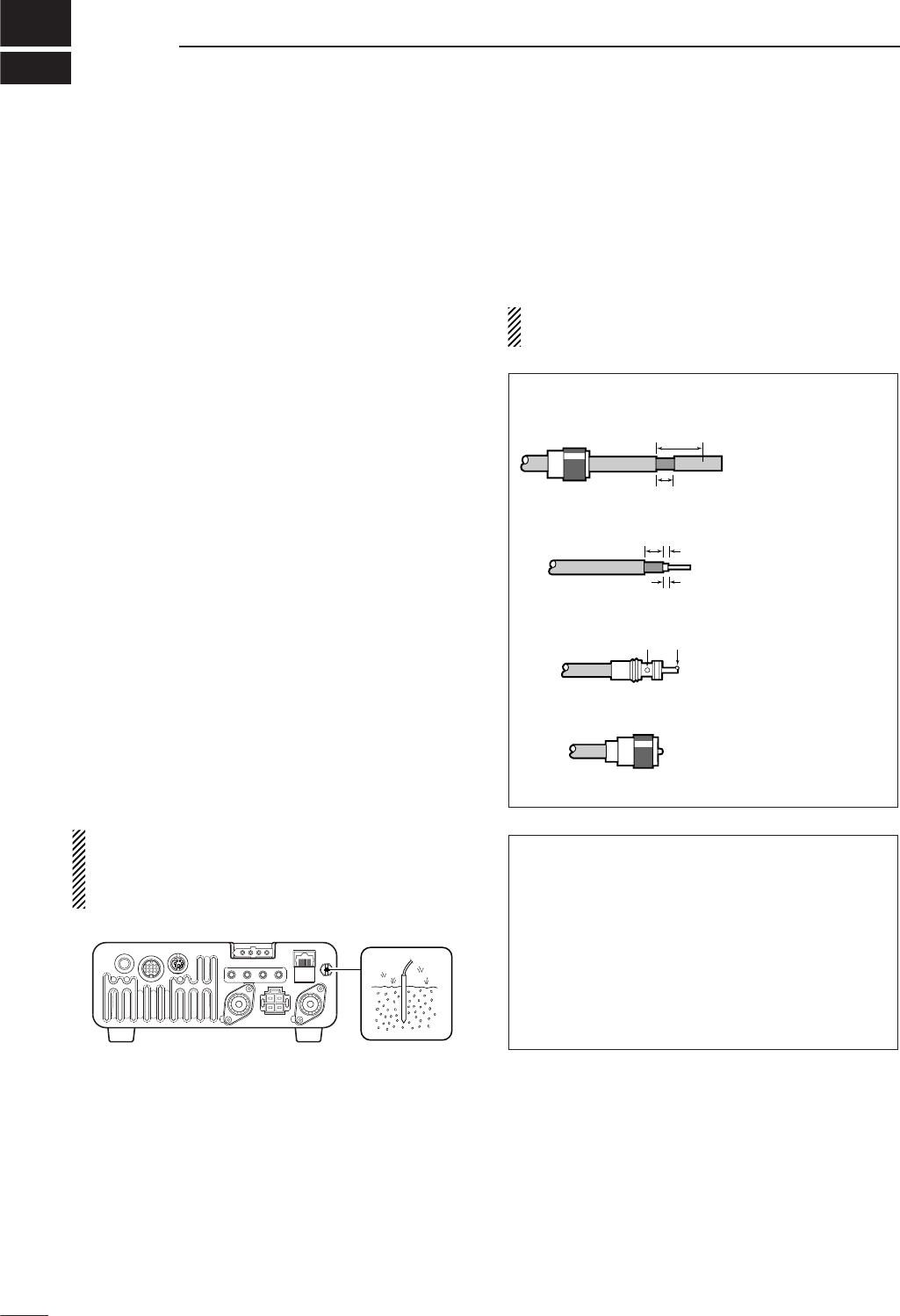
■Grounding
To prevent electrical shock, television interference
(TVI), broadcast interference (BCI) and other prob-
lems, ground the transceiver through the GROUND
terminal on the rear panel.
For best results, connect a heavy gauge wire or strap
to a long, buried copper rod. Make the distance be-
tween the [GND] terminal and ground as short as pos-
sible.
RWARNING: NEVER connect the [GND] ter-
minal to a gas pipe or electric conduit, since the
connection could cause an explosion or electric
shock.
■Antenna connection
For radio communications the antenna is of critical im-
portance for output power and sensitivity. Use well-
matched 50-ohm antennas and coaxial feedline. An
SWR (standing wave radio) of 1.5:1 or lower is recom-
mended when transmitting.
CAUTION: Protect your transceiver from lightning
by using a lightning arrestor.
ANTENNA SWR
Each antenna is tuned for a specified frequency
range and SWR increases outside that range. When
the SWR is higher than approx. 2.0 : 1, the trans-
ceiver’s power drops to protect the final transistors.
In this case, an antenna tuner is used to match the
transceiver and antenna. Low SWR allows full power
for transmitting even when using the antenna tuner.
The IC-7000 has an SWR meter to monitor the an-
tenna SWR continuously.
30 mm
10 mm (soft solder)
10 mm
1–2 mm
solder solder
Soft
solder
Coupling ring
PL-259 CONNECTOR INSTALLATION EXAMPLE
q
e
r
w
Slide the coupling ring
down. Strip the cable
jacket and soft solder.
Slide the connector
body on and solder it.
Screw the coupling
ring onto the connector
body.
Strip the cable as
shown at left. Soft
solder the center con-
ductor.
2
2
16
INSTALLATION AND CONNECTIONS
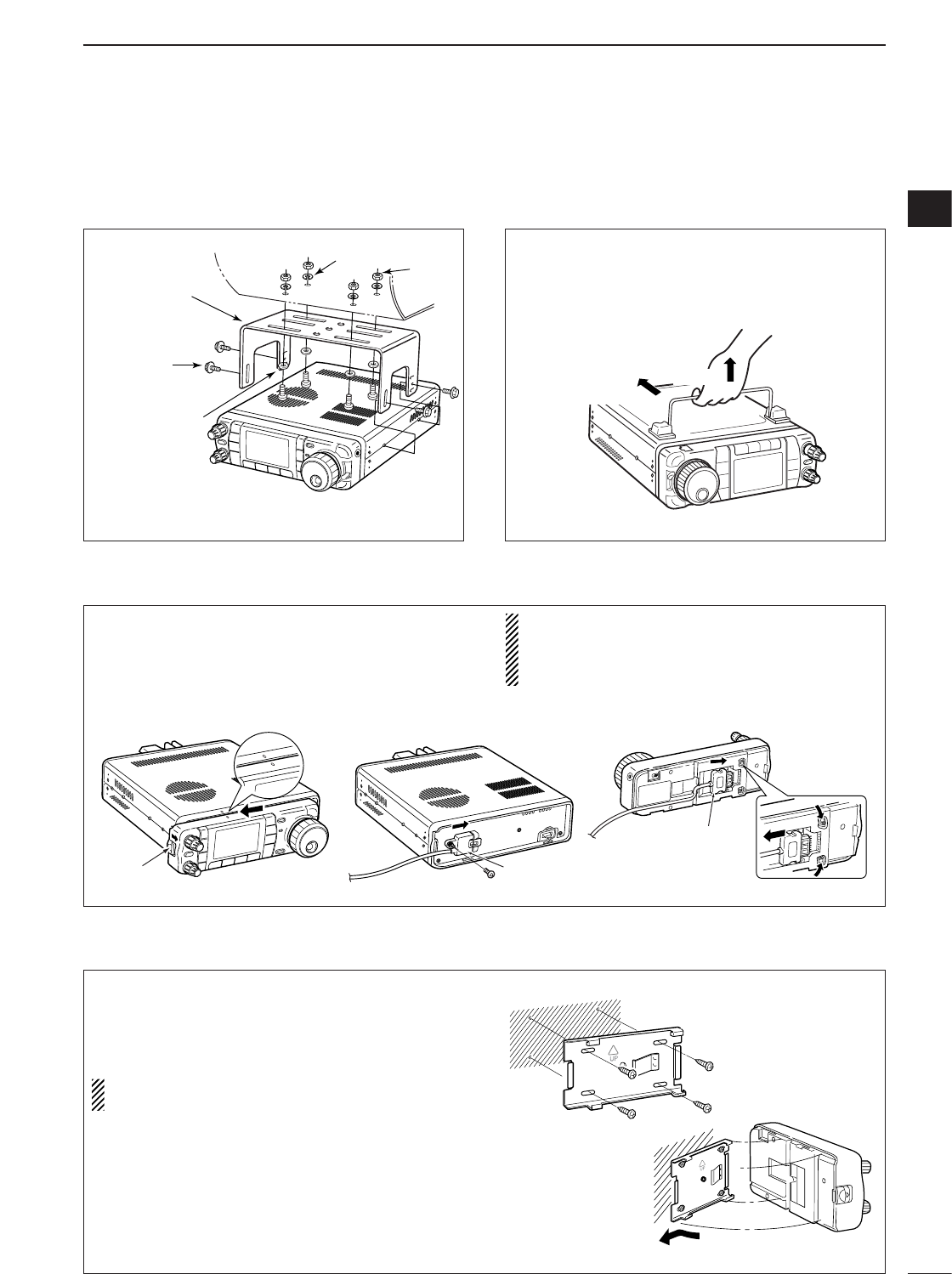
■Installation
DSingle body mounting DStand
*CAUTION: Non-supplied screws (longer than 8 mm)
may damage the internal units.
MB-62
(optional)
Supplied with
the MB-62*
Nut
Spring washer
Flat washer
Pull back
then up
DFront panel separation
DFront panel mounting
qWhile pulling the front panel latch towards you,
slide the front panel to the left (fig. 1).
wAttach the optional OPC-1443 to the main body
and tighten the supplied screw as in fig. 2.
eAttach the other end of the OPC-1443 to the de-
tached front panel as in fig. 3.
CAUTION: NEVER detach/attach the front panel
when connecting the DC power supply (or battery).
Be sure to disconnect the DC power cable from the
[13.8 V] socket on the transceiver rear panel.
qAttach the MB-105 to a flat surface using the four
supplied screws (fig. 1).
wFix the detached front panel to the MB-105 as il-
lustrated in fig. 2.
BE CAREFUL to mount the MB-105 so that the
front panel attaches with the correct side up.
Separation cable
(OPC-1443)
Separation cable
(OPC-1443)
To remove
fig. 1 fig. 2 fig. 3
Latch
fig. 1
fig. 2
To raise the stand:
With the transceiver upside down, pull the stand to-
wards the rear panel and then upwards, as illus-
trated below.
17
2INSTALLATION AND CONNECTIONS
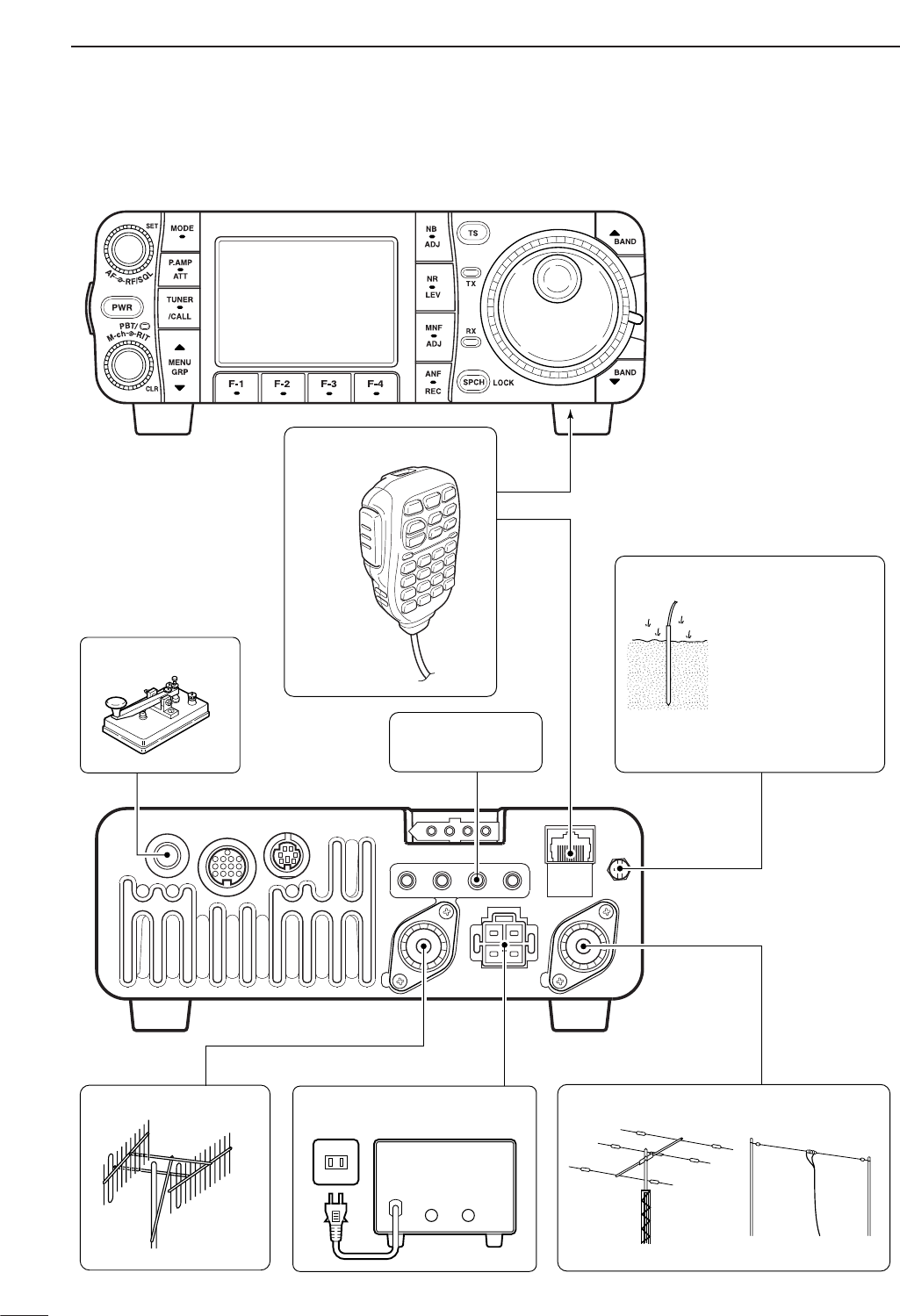
■Required connections
KEY ACC DATA MIC
ANT2 ANT1
DC 13.8V
GND
MICROPHONE(p. 10)
HF/50 MHz ANTENNA
GROUND(p. 15)
HM-151
RTTY TERMINAL
UNIT (p. 23)
Use the heaviest
gauge wire or strap
available and make
the connection as
short as possible.
Grounding prevents
electrical shocks, TVI
and other problems.
2 m/70 cm ANTENNA
STRAIGHT KEY
DC POWER SUPPLY (p.19)
A DC power supplyAC outlet
13.8 V; at least 25 A
Black
_
Red
+
18
2
INSTALLATION AND CONNECTIONS
2
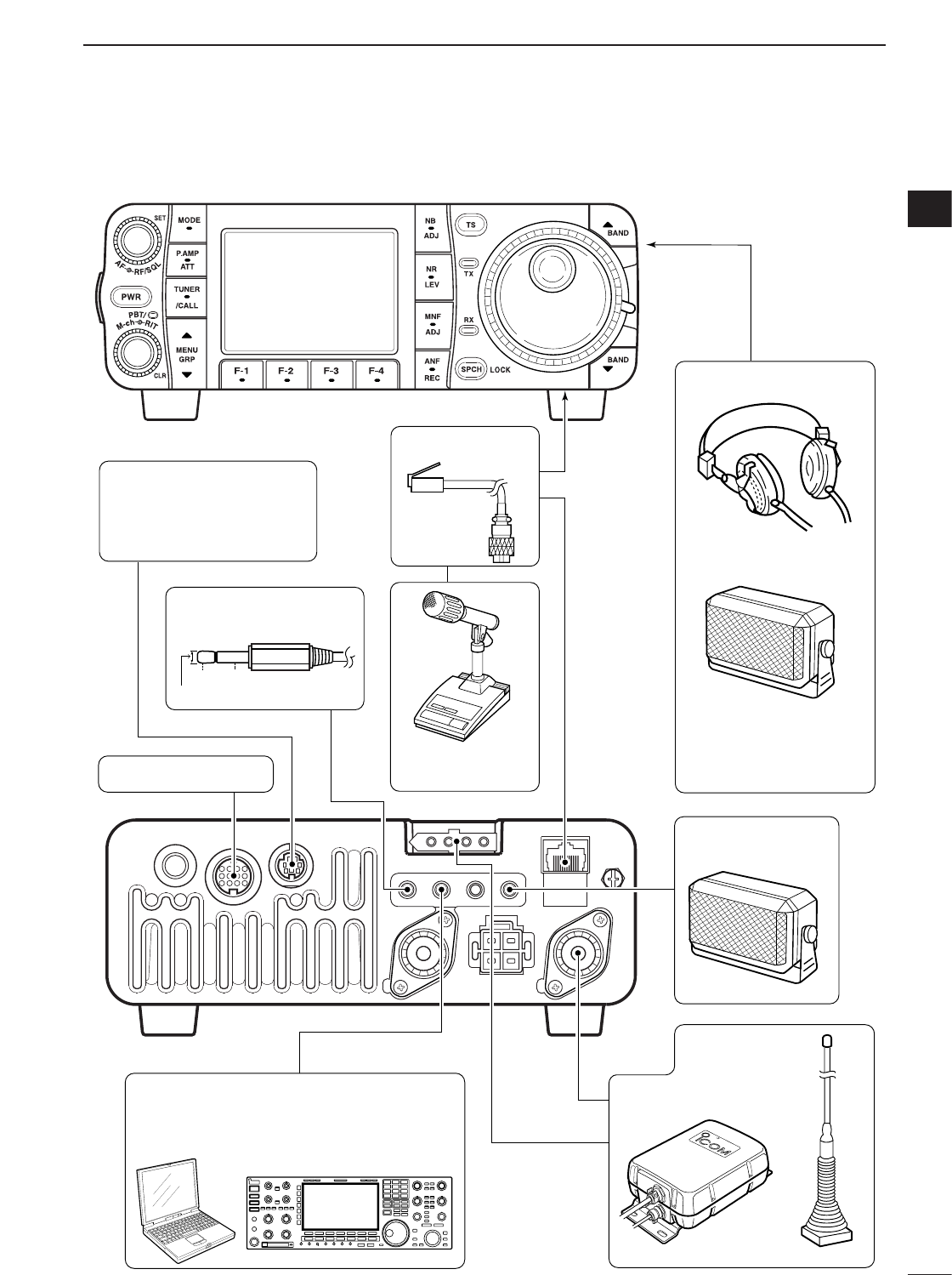
■Advanced connections
KEY ACC DATA MIC
ANT2 ANT1
DC 13.8V
GND
OPC-589 (p. 152)
DESKTOP (p. 151)
MICROPHONE
SPEAKER
ACC SOCKET(p. 12)
DATA SOCKET (p. 12)
VIDEO OUT
AH-4 (p. 20) AH-2b
EXTERNAL
SPEAKER (p. 151)
HEADPHONES
SP-7/SP-10
SM-20
or
REMOTE(p. 144)
Used for computer control and transceive
operation.
Selectable with the
[PHONE/SPEAKER]
switch on the back of
the front panel.
6-pin mini DIN socket to
connect to a TNC, etc. for
packet operation.
to [VOUT] jack
3.5(d) mm
GND
Vout
19
2INSTALLATION AND CONNECTIONS
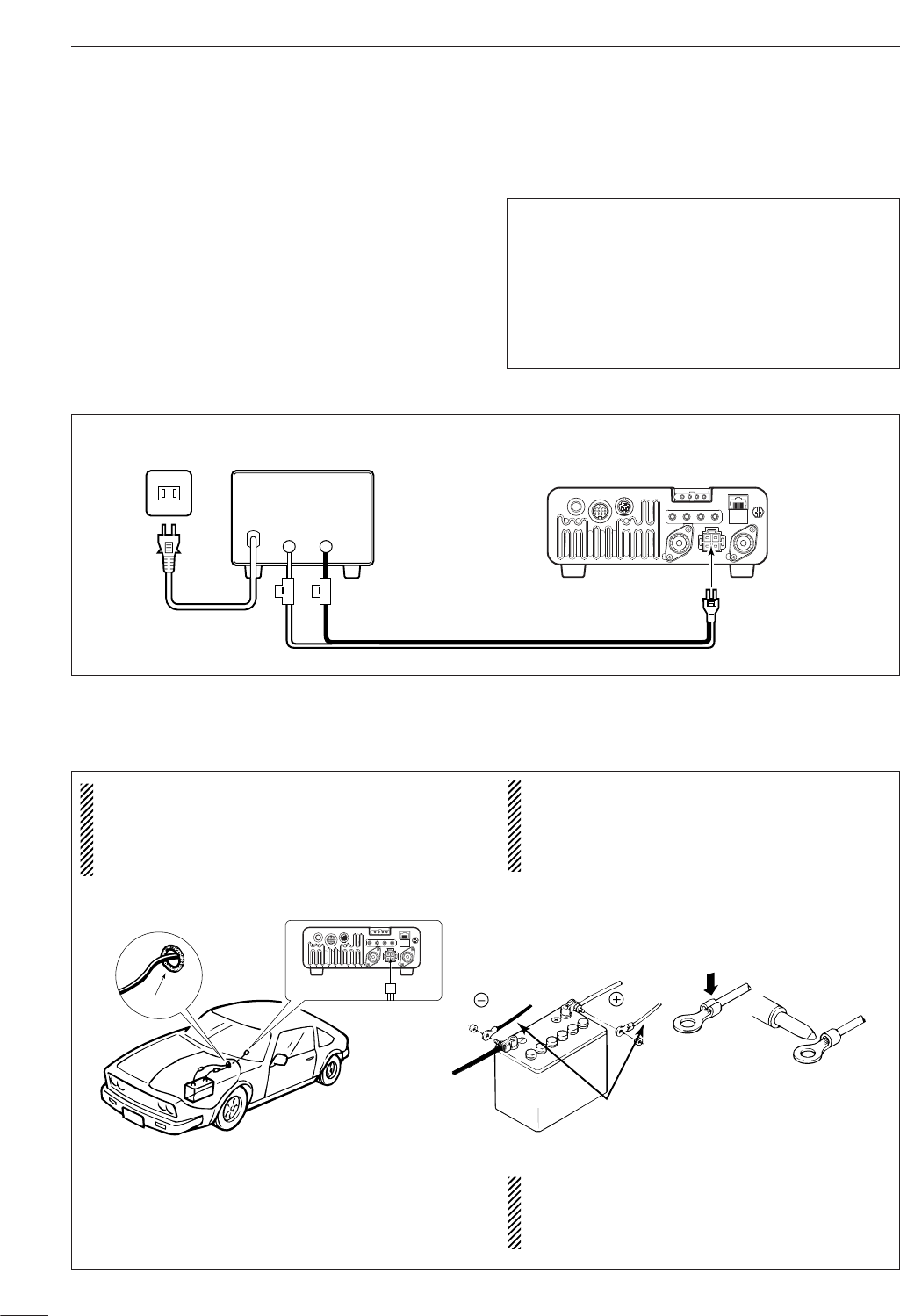
■Power supply connections
Use the DC power supply with a 25 A capacity when
operating the transceiver with AC power. Refer to the
diagrams below.
CAUTION: Before connecting the DC power
cable, check the following important items. Make
sure:
•The [POWER] switch is OFF.
•Output voltage of the power source is 12–15 V.
• DC power cable polarity is correct.
Red : positive +terminal
Black : negative _terminal
A DC power supplyAC outlet
AC cable
30 A fuses Supplied
DC power cable
13.8 V; at least 25 A
Black
_
Red
+
Transceiver
DC power
socket
■Battery connections
•RWARNING NEVER connect to a battery
without supplying a DC fuse, otherwise a fire
hazard occurs.
•NEVER connect the transceiver directly to a 24 V
battery.
•DO NOT use the cigarette lighter socket for power
connections. (See p. 11 for details)
•Attach a rubber grommet when passing the DC
power cable through a metal plate to prevent a
short circuit.
IMPORTANT!
Detailed installation notes for Icom mobile trans-
ceivers to be fitted into vehicles are available. Con-
tact your Icom dealer or distributor.
Grommet
CONNECTING A VEHICLE BATTERY
Note: Use terminals for
the cable connections.
Crimp
Solder
Supplied
DC power cable
red
black
12 V
battery
■Connecting a DC power supply
20
2
INSTALLATION AND CONNECTIONS
2
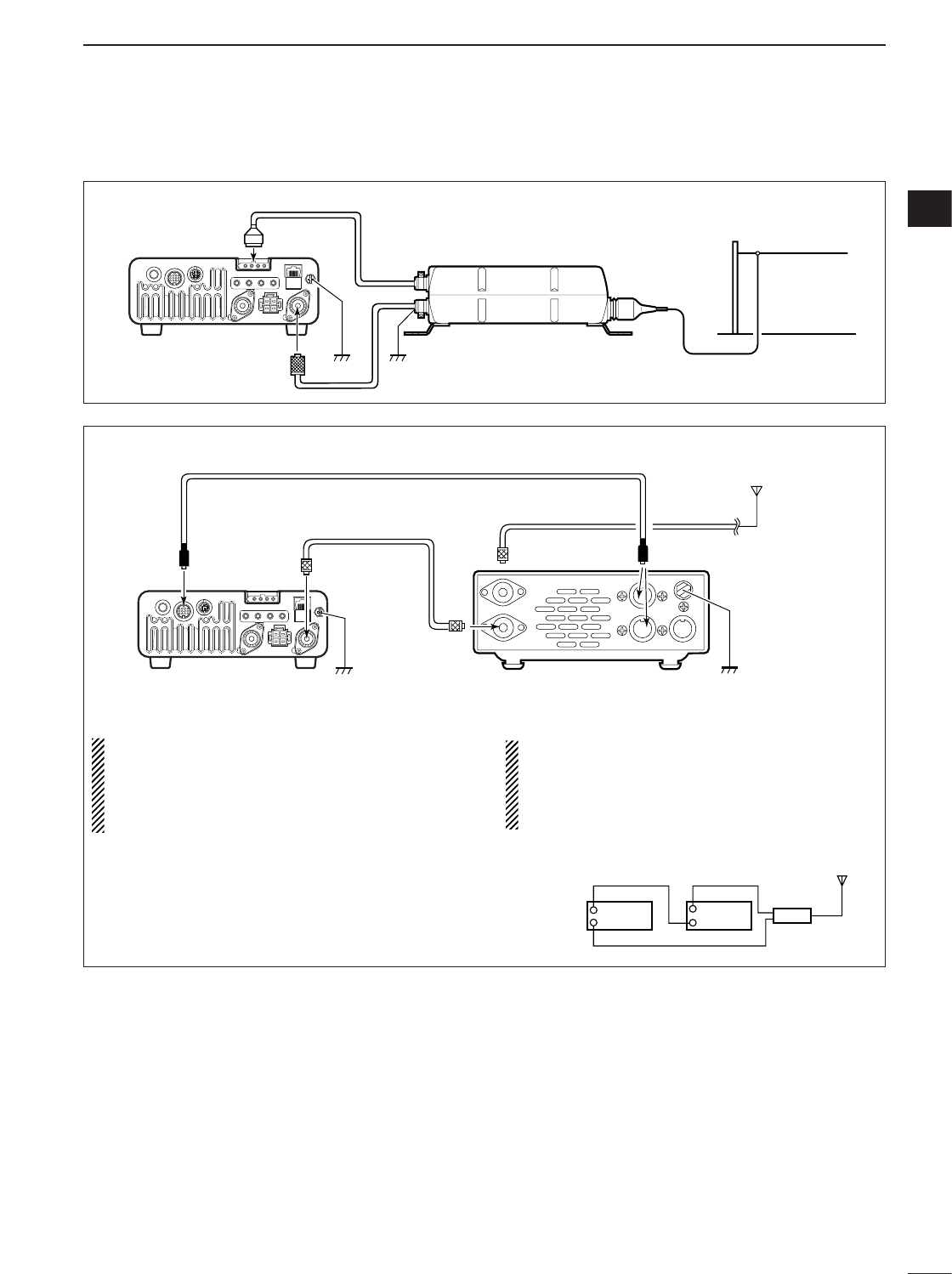
■External antenna tuners
GroundGround
Long wire or optional AH-2b
AH-4
ANT1
IC-7000
Coaxial cable
(from the AH-4)
CONNECTING THE AH-4
CONNECTING THE AT-180
•Turn the IC-7000’s power OFF when connecting
the AT-180, otherwise, the CPU may malfunction
and the AT-180 may not function properly.
•The OPC-742 is required when using both the AT-
180 and a 2m/70cm linear amplifier.
• Do not connect [ANT2] to the AT-180. When using
an HF to 2m/70cm dual or wide-band antenna,
use a duplexer between the AT-180 and antenna
since 2 m/70 cm signals do not pass through the
AT-180.
[ANT 1]
Transceiver
Duplexer
HF to 2 m/70 cm
antenna
AT-180
[ANT 2]
IC-7000
Ground Ground
AT-180
HF
to 6 m
antenna
[TRANSCEIVER]
[ANT][ANT1][ACC] [ACC]
ACC cable supplied with the AT-180
Coaxial cable supplied
with the AT-180
Either of the two
external connectors
21
2INSTALLATION AND CONNECTIONS
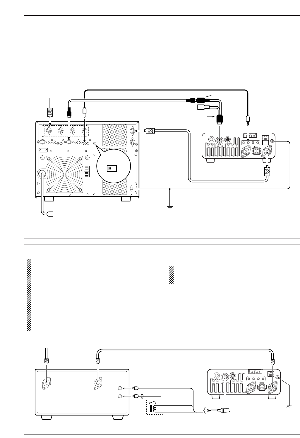
■Linear amplifier connections Use the [ANT1] connector when connecting an HF/50
MHz linear amplifier.
CONNECTING THE IC-PW1/EURO
To an
antenna ACC-1
ANT
ANT1
ACC
INPUT1
REMOTE
EXCITER
11&2
GND
GND
IC-PW1/EURO
AC outlet
Non-European versions : 100–120/220–240 V
European version : 230 V
Ground
Transceiver
REMOTE
Remote control cable (supplied with the IC-PW1/EURO)
ACC cable (supplied with the IC-PW1/EURO)
Coaxial cable
(supplied with the IC-PW1/EURO)
7-pin side
OPC-599 conversion cable
()
CONNECTING A NON-ICOM LINEAR AMPLIFIER
RWARNING:
•Set the transceiver output power and linear ampli-
fier ALC output level referring to the linear ampli-
fier instruction manual. Be sure the linear ampli-
fier keying circuit control voltage is compatible
with the IC-7000, before connecting to HSEND
line (ACC cable).
•The ALC input level must be in the range 0 V to
–4 V, and the transceiver does not accept positive
voltage. Non-matched ALC and RF power settings
could cause a fire or damage the linear amplifier.
•The IC-7000 SEND relay is rated at 16 V and a
0.5 A DC. If these levels are exceeded, a larger
external relay must be used.
HSEND
(Orange)
ALC (Blue)
13.8V (Gray)
Ground
GND
Relay
RF INRF OUT
ALC
KEY
ANT1
ACC cable
ACC
Transceiver
50 1 coaxial cable
To a n
antenna
22
2
INSTALLATION AND CONNECTIONS
2
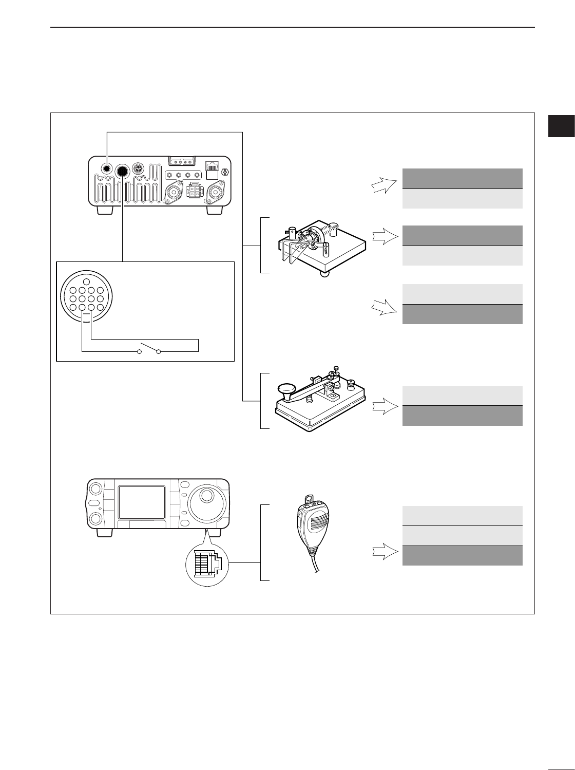
Rear panel
Paddle
[KEY]
[MICROPHONE]
Straight key
Microphone (HM-103)
Keyer set mode setting
Keyer set mode (p. 49)
4
8
12
[ACC]
123
765
9
10 11
13
For no break-in operation:
Connect an external switch
such as a foot switch; or use
the RTTY SEND terminal for
all bands. (See p. 23)
See p. 50 for connection details:
Paddle operation from [MIC]
connector
.
Normal
Reverse
Bug
Paddle polarity Normal
MIC U/D keyer (HM-103) ON
Keyer Type ELEC-KEY
Paddle polarity Normal
Keyer Type Straight
Paddle polarity Normal
Keyer Type ELEC-KEY
Paddle polarity Reverse
Keyer Type ELEC-KEY
Paddle polarity Normal
Keyer Type BUG-KEY
■Connections for CW
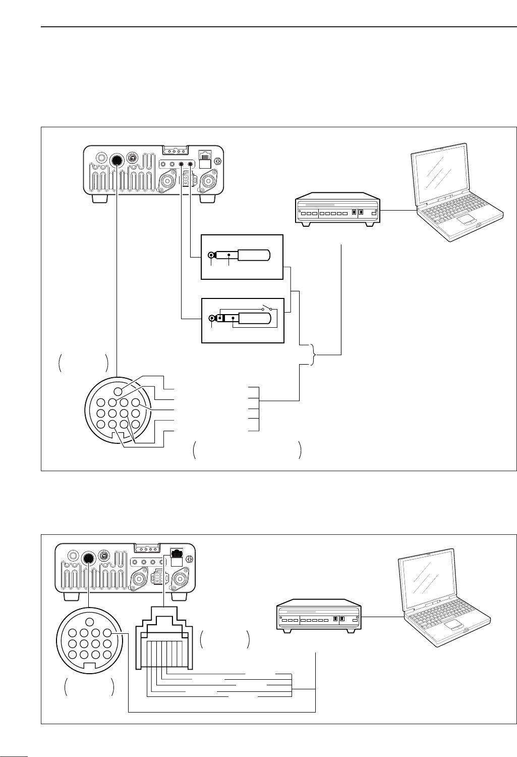
23
2INSTALLATION AND CONNECTIONS
[ACC]
Rear panel
4
8
12
123
765
9
10 11
13
[RTTY] [EXT SP]
TU or TNC
Personal computer
Rear panel
view
Colors refer to connection
to the supplied ACC cable.
*1Connect SQL line when required.
eHF/50 MHz: orange
u144/430 MHz: purple
*2
SQL*1 (light green)
FSKK (black)
AF out (light blue)
MSEND*2
GND (red)
GND
GND
AF
3-conductor 1/8˝ plug (supplied)
2-conductor 1/8˝ plug
FSKK
SEND
DWhen connecting to [ACC] socket
DWhen connecting to [MIC] connector
[MIC][ACC]
Rear panel
i SQL
!2 AF out (light blue)
r PTT
t GND y MIC
u GND
Rear panel
view TU or TNC
Personal computer
4
8
12
123
765
9
10 11
13
Rear panel
view
■Connections for RTTY (FSK)
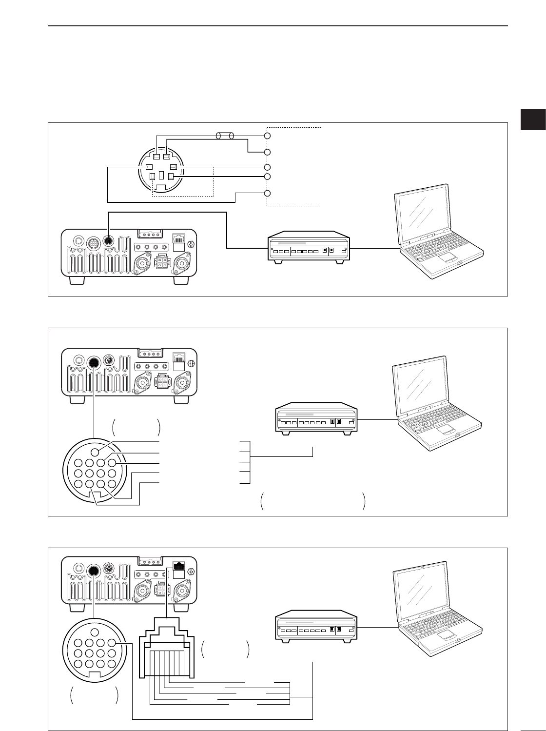
24
2
INSTALLATION AND CONNECTIONS
2
■Connections for packet
DWhen connecting to [DATA] socket
DWhen connecting to [MIC] connector
DWhen connecting to [ACC] socket
[MIC][ACC]
Rear panel
i SQL
!2 AF out (light blue)
r PTT
t GND y MIC
u GND
Rear panel
view TU or TNC
Personal computer
4
8
12
123
765
9
10 11
13
Rear panel
view
[DATA] (Rear panel)
Personal computer
TU or TNC
RS-232C
PTT
PTTP
DATA IN
SQL
RX AUDIO
GND
TX AUDIO
qw
e
yt
r
AF OUT
DATA OUT
GND
SQL
[ACC]
Rear panel
4
8
12
123
765
9
10 11
13
Rear panel
view
Colors refer to connection
to the supplied ACC cable.
*1Connect SQL line when required.
SQL*1 (light green)
AF in (pink)
AF out (light blue)
MSEND (orange)
GND (red)
TU or TNC
Personal computer
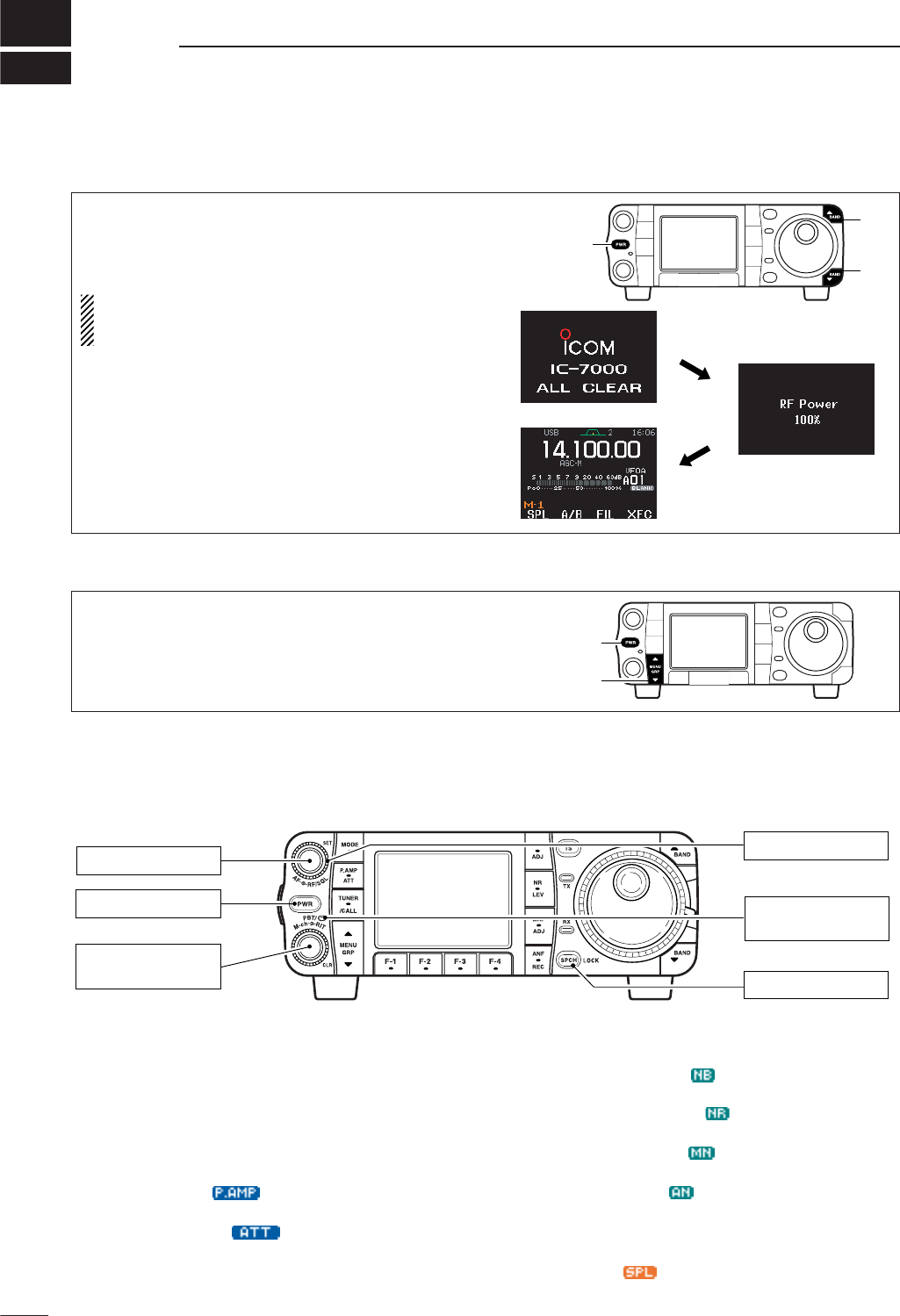
3
25
BASIC OPERATION
■When first applying power (CPU resetting)
Before first applying power, make sure all connec-
tions required for your system are complete by refer-
ring to Chapter 2. Then, reset the transceiver using
the following procedure.
Resetting CLEARS all programmed contents in
memory channels and returns programmed values
in set mode.
qMake sure the transceiver power is OFF.
wWhile pushing [Y(
BAND
)] and [Z(
BAND
)], push
[PWR] for 1 sec. to start resetting.
• The internal CPU is reset.
•The display changes to ‘ALL CLEAR,’ ‘RF power 100%’
and ‘Initial frequency and Mode’ as shown at right.
The transceiver’s
initial frequency and mode
[PWR]
[Y]
[Z]
[RF/SQL]: Center
[LOCK]: OFF
[POWER]: OFF
[AF]: Max. CCW
[PBT]: Center
(Push and hold for 1 sec.)
[PBT/M-ch/RIT]
: PBT
(indicator lights)
CCW : counterclockwise
DMenu resetting (M
-
1)
Turn power ON, then check the display. If any of the
following indicators appear, turn them OFF as follows:
•Tuning step indicators,
Z
, (SSB, CW or RTTY):
Push [TS].
•MHz tuning step indicator,
Z
, (FM, WFM or AM):
Push [TS]
• 1 Hz frequency readout (SSB, CW or RTTY):
Push and hold [TS].
• Preamp indicator, :
Push [P.AMP/ATT]
• Attenuator indicator, :
Push [P.AMP/ATT]
• Noise blanker indicator, :
Push [NB/ADJ]
• Noise reduction indicator, :
Push [NR/LEV]
• Manual notch indicator, :
Push [MNF/ADJ]
• Auto notch indicator, :
Push [ANF/•REC]
• Memory mode indicator, MEMO:
Use [F-4 V/M]in the M
-
2menu (p. 27).
• Split indicator, :
Use [F-1 SPL]in the M
-
1menu (p. 91).
If you can’t figure out how to return to the menu M
-
1:
While pushing either [Y(
MENU
/
GRP
)] or [Z
(
MENU
/
GRP
)], turn power ON.
•The other groups are also reset to S
-
1or G
-
1(Scope) in
this time.
[PWR]
[MENU/GRP]
After resetting the transceiver, set controls and
switches as shown in the diagram below.
■Initial settings
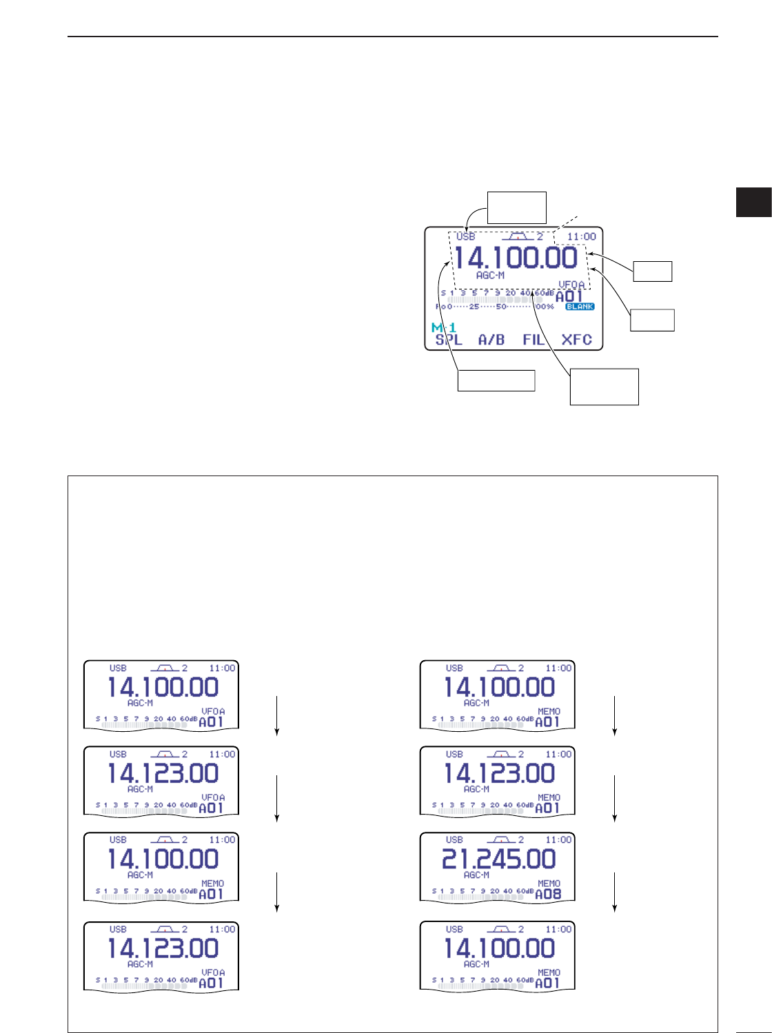
DDifferences between VFO and memory mode
VFO MODE
Each VFO shows a frequency and operating mode. If
the frequency or operating mode is changed, the VFO
automatically memorizes the new frequency or oper-
ating mode.
When VFO settings are changed with frequency and
mode from another VFO or memory mode, the last-
used frequency and operating mode for that VFO ap-
pear.
[EXAMPLE]
MEMORYMODE(pgs. 102–110)
Each memory channel shows a frequency and oper-
ating mode like a VFO. Even if the frequency or mode
is changed, the memory channel does not memorize
the new frequency or operating mode.
When a memory channel is changed with frquency
and mode from another memory channel or VFO
mode, the memorized frequency and operating mode
appear.
[EXAMPLE]
26
3
BASIC OPERATION
3
VFO is an abbreviation of Variable Frequency Oscilla-
tor, and traditionally refers to an oscillator.
The IC-7000 VFO is somewhat different. The VFO dis-
play of the IC-7000 acts like a computer’s window and
can show one frequency and one operating mode.
You can call up a desired frequency to the VFO with
the memo pad-read key (p. 112) or the memory trans-
fer function (p. 109). You can also change the fre-
quency with [DIAL] and select an operating mode with
[MODE] key or call up previously accessed frequency
and modes with the band stacking register (p. 28).
The IC-7000 has two VFOs, specially suited for split
frequency operation. The VFOs are called VFO A and
VFO B. You can use the desired VFO to call up a fre-
quency and operating mode for operation.
VFO
MODE
KEY
Select
MEMORY
CHANNEL
DIAL
MEMO PAD
28.025 MHz
7.001 MHz
21.295 MHz
BAND
Change
Transfer
Transfer Transfer
Changed frequency (14.123 MHz) does not appear and
memorized frequency (14.100 MHz) appears instead.
Memory channel 1 is
selected.
The frequency is changed.
Memory channel 1 is
selected again.
Another memory channel
is selected.
VFO is selected.
The frequency is changed.
VFO is selected again.
Changed frequency (14.123 MHz) appears.
Memory mode is selected.
■VFO description
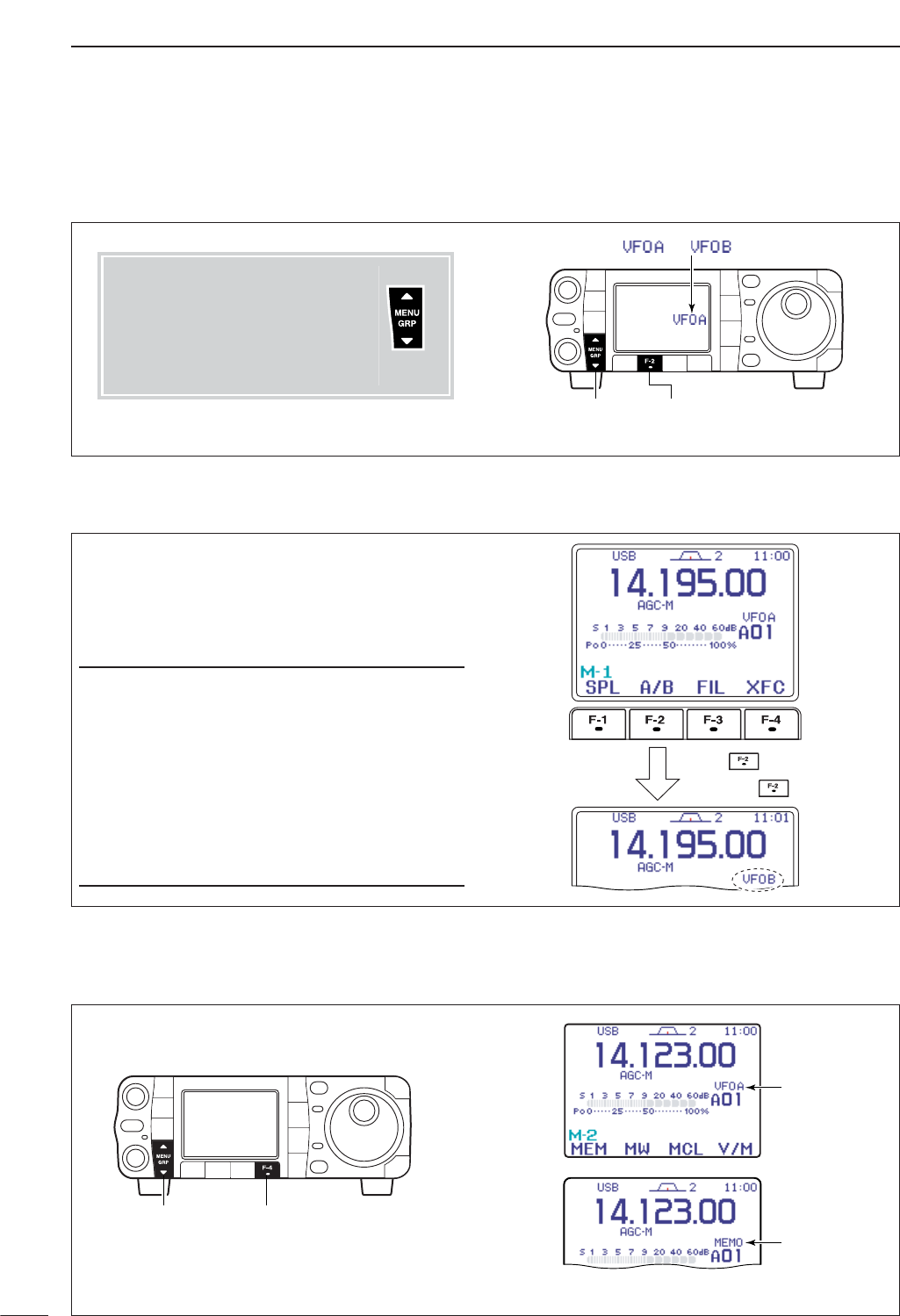
■Selecting VFO/memory mode
27
3BASIC OPERATION
qSelect M
-
1.
wPush [F-2 A/B]to toggle VFO A or VFO B.
[MENU/GRP] [F-2]
Either “ ” or “ ” appears.
DSelecting VFO A/VFO B
qSelect M
-
1.
wPush [F-2 A/B]for 1 sec. to set the undisplayed
VFO frequency and mode to those of the displayed
VFO.
•Three beeps sound when the VFO equalization is com-
pleted.
CONVENIENT
Use two VFOs as a quick memory
When you find a new station, but you wish to continue
searching, the Two VFO system can be used for quick
memory storage.
qPush [F-2 A/B]for 1 sec. to store the displayed fre-
quency into the undisplayed VFO.
wContinue searching for stations.
ePush [F-2 A/B]to retrieve the stored frequency.
rTo continue searching for a station, push [F-2 A/B]
again.
Push
then push again.
for 1 sec.,
DVFO equalization
■VFO operation
qSelect M
-
2.
wPush [F-4 V/M]to toggle VFO and memory
modes.
“VFO” indicator
Memory channel
indicator
[MENU/GRP] [F-4]
Menu group selection
Push [MENU/GRP] for 1 sec.
Selection from:
M
,
S
or
G
(Graphic)
Menu selection (Example: M)
Push [MENU/GRP] momentarily.
Selection from:
M
-
1
,
M
-
2
or
M
-
3
Either
Y or Z
Either
Y or Z
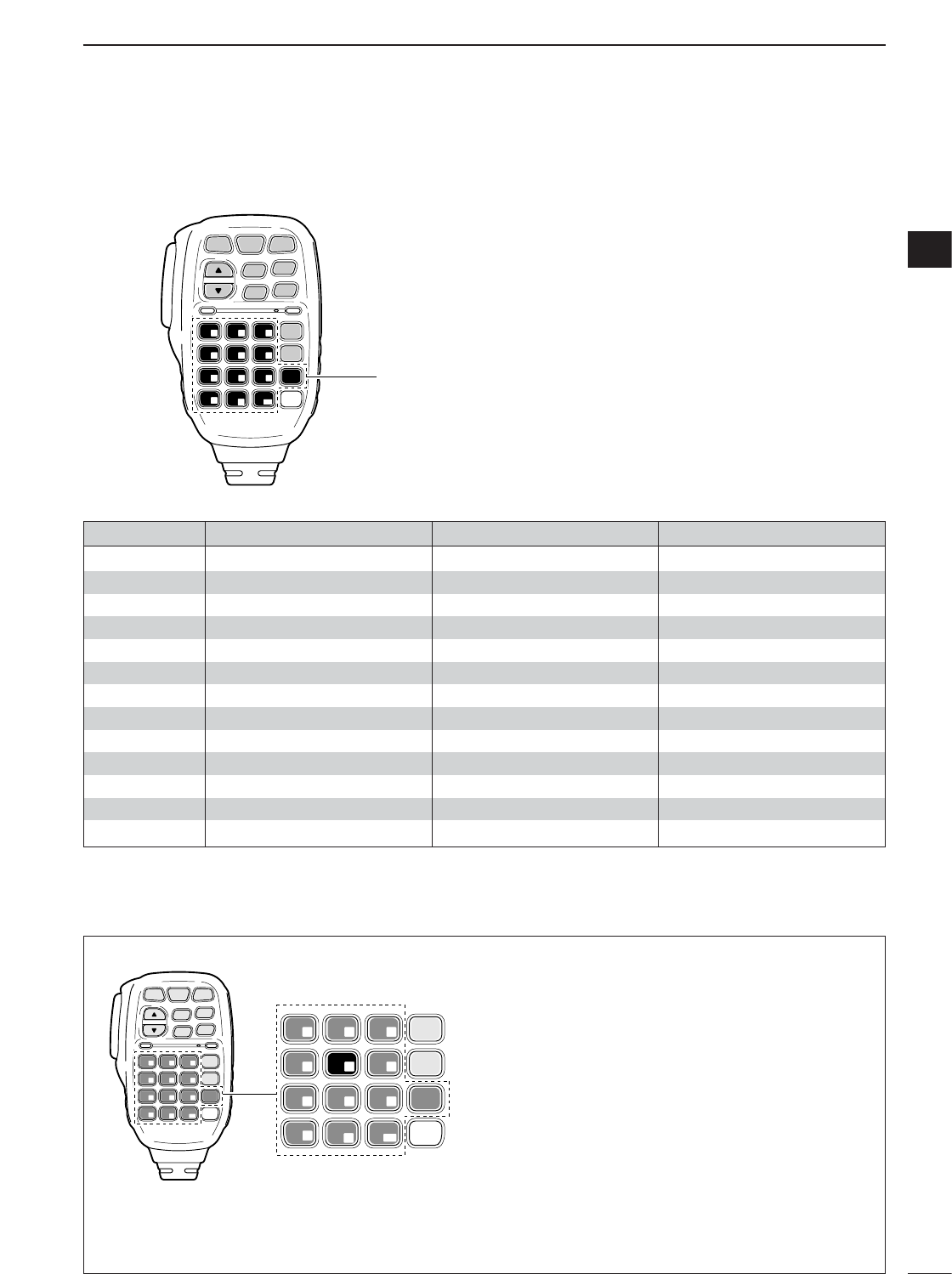
28
3
BASIC OPERATION
3
The triple band stacking register provides 3 memories
in one band. 3 sets of frequency and operating mode
on each band are automatically stored when used.
If a band key (on the HM-151) is pushed once, the last
used frequency and operating mode are called up.
When the key is pushed again, another stored fre-
quency and operating mode are called up.
This function is convenient when you operate 3 oper-
ating modes on one band. For example, one register
is used for a CW frequency, another for an SSB fre-
quency and the other one for an RTTY frequency.
See the table below for a list of the bands available
and the default settings for each band.
SPCH
/LOCK
TUNER
/CALL XFC
V/M
F-1 F-2
FIL
MODE
GENE
MW
123
456
789
.0CE
F-INP
ENT
1.8 3.5 7
10 14 18
21 24 28
50 144 430
Band keys
HM-151
■Selecting an operating band
BAND REGISTER 1 REGISTER 2 REGISTER 3
1.8 MHz 1.900000 MHz CW 1.910000 MHz CW 1.915000 MHz CW
3.5 MHz 3.550000 MHz LSB 3.560000 MHz LSB 3.580000 MHz LSB
7 MHz 7.050000 MHz LSB 7.060000 MHz LSB 7.020000 MHz CW
10 MHz 10.120000 MHz CW 10.130000 MHz CW 10.140000 MHz CW
14 MHz 14.100000 MHz USB 14.200000 MHz USB 14.050000 MHz CW
18 MHz 18.100000 MHz USB 18.130000 MHz USB 18.150000 MHz USB
21 MHz 21.200000 MHz USB 21.300000 MHz USB 21.050000 MHz CW
24 MHz 24.950000 MHz USB 24.980000 MHz USB 24.900000 MHz CW
28 MHz 28.500000 MHz USB 29.500000 MHz USB 28.100000 MHz CW
50 MHz 50.100000 MHz USB 50.200000 MHz USB 51.000000 MHz FM
144 MHz 145.000000 MHz FM 145.100000 MHz FM 145.200000 MHz FM
430 MHz 433.000000 MHz FM 433.100000 MHz FM 433.200000 MHz FM
General 15.000000 MHz USB 15.100000 MHz USB 15.200000 MHz USB
qPush [(14)5], then select a frequency and an oper-
ating mode.
•Frequency and operating mode are memorized in the
first band stacking register.
wPush [(14)5] again, then select another frequency
and operating mode.
•This frequency and operating mode are memorized in
the second band stacking register.
ePush [(14)5] again, then select another frequency
and operating mode.
•This frequency and operating mode are memorized in
the third band stacking register.
•When a fourth frequency and operating mode are se-
lected on a band, the first register set in step q, is over
written.
SPCH
/LOCK
TUNER
/CALL XFC
V/M
F-1 F-2
FIL
MODE
GENE
MW
123
456
789
.0CE
F-INP
ENT
1.8 3.5 7
10 14 18
21 24 28
50 144 430
FIL
MODE
GENE
123
456
789
.0CE
F-INP
ENT
1.8 3.5 7
10 14 18
21 24 28
50 144 430
[Example]: 14 MHz band
HM-151
DUsing the band stacking registers
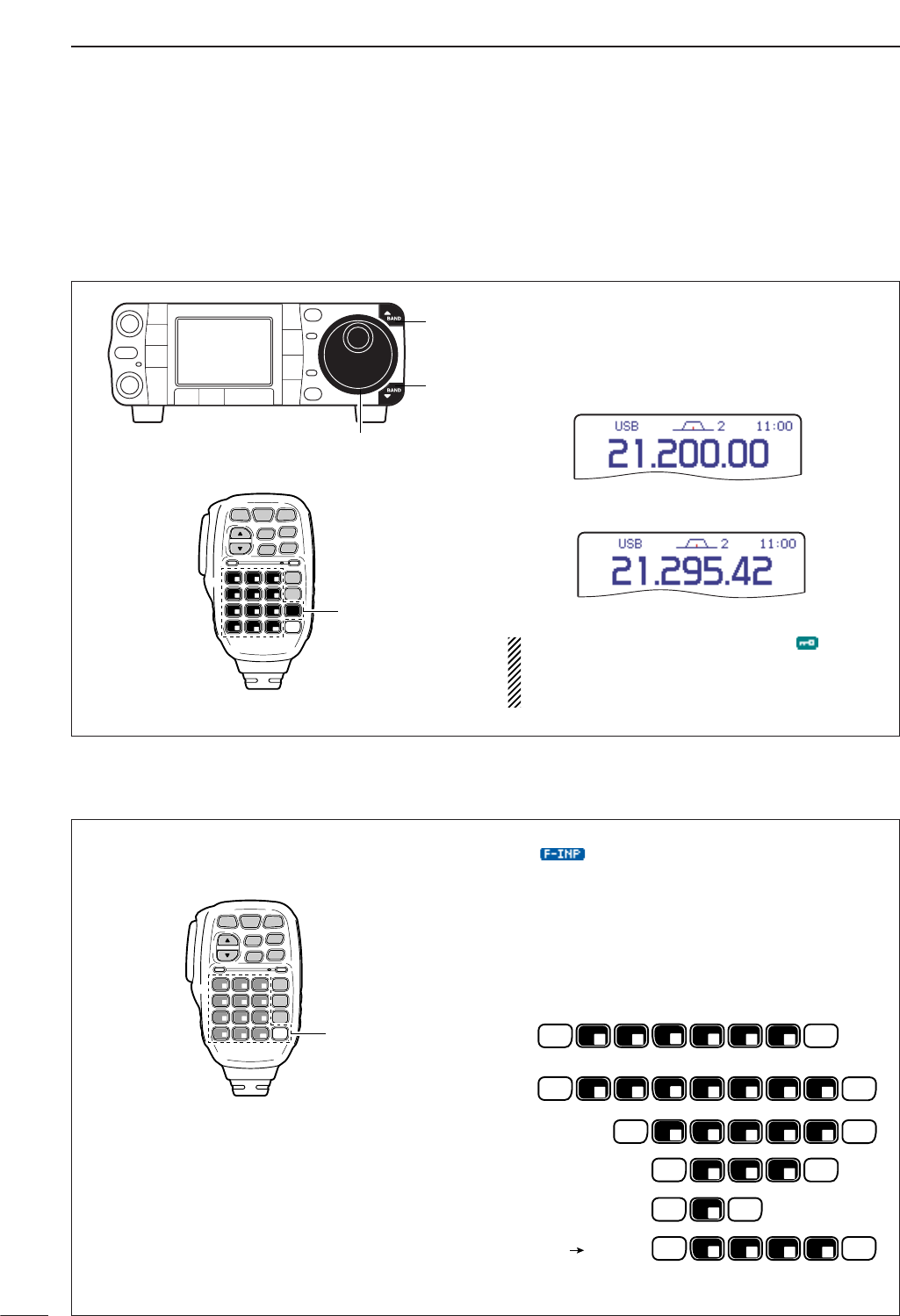
29
3BASIC OPERATION
The transceiver has several tuning methods for conve-
nient frequency tuning.
■Frequency setting
DTuning with the main dial
qPush [Y(
BAND
)] or [Z(
BAND
)] to select the desired
band. Or push the desired band key on the micro-
phone 1–3 times.
•Three different frequencies can be selected on each
band with the microphone’s band key. (See previous
page “Using the band stacking register.”)
wRotate [DIAL] to set the desired frequency.
If the dial lock function is activated, “ ” indicator
lights, and [DIAL] does not function. In this case,
push [SPCH/LOCK] to deactivate the lock func-
tion. (p. 37)
SPCH
/LOCK
TUNER
/CALL XFC
V/M
F-1 F-2
FIL
MODE
GENE
MW
123
456
789
.0CE
F-INP
ENT
1.8 3.5 7
10 14 18
21 24 28
50 144 430
Band keys
HM-151
[Y]
[Z]
[DIAL]
DDirect frequency entry with the microphone’s keypad
The HM-151 has a keypad for direct frequency entry
as described right.
qPush [F-INP/ENT].
• “ ” appears.
wInput the desired frequency.
•Push [(50)•] to input “ • (decimal point)” between the
MHz digits and kHz digits.
ePush [F-INP/ENT] to set the input frequency.
•To cancel the input, push [CE] instead of [F-INP/ENT].
[EXAMPLES]
F-INP
ENT
F-INP
ENT
F-INP
ENT
F-INP
ENT
F-INP
ENT
F-INP
ENT
F-INP
ENT
F-INP
ENT
F-INP
ENT
F-INP
ENT
F-INP
ENT
1
1.8
1
1.8
1
1.8
2
3.5
2
3.5
2
3.5
4
10
4
10
5
14
5
14
5
14
F-INP
ENT
5
14
6
18
7
21
7
21
7
21
8
24
.
50
.
50
.
50
.
50
.
50
0
144
0
144
0
144
0
144
21.280 21.245
14.025 MHz
18.0725 MHz
706 kHz
5.100 MHz
7.000 MHz
SPCH
/LOCK
TUNER
/CALL XFC
V/M
F-1 F-2
FIL
MODE
GENE
MW
123
456
789
.0CE
F-INP
ENT
1.8 3.5 7
10 14 18
21 24 28
50 144 430 Keypad
HM-151
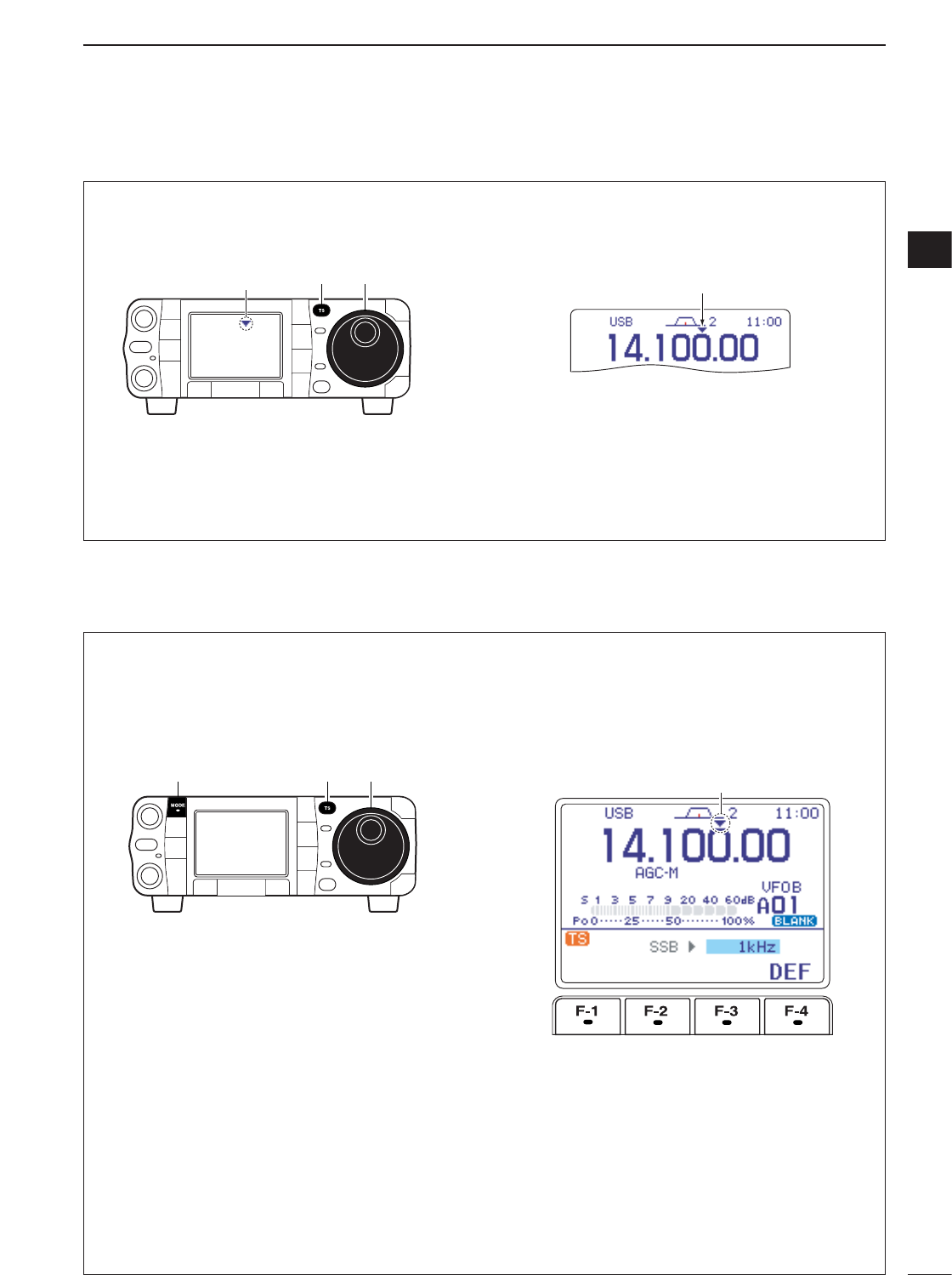
30
3
BASIC OPERATION
3
DProgrammable tuning step
The operating frequency can be changed in steps of
(0.01 (AM/FM/WFM only), 0.1, 1, 5, 9, 10, 12.5, 20 25
or 100 kHz selectable) for quick tuning.
qPush [TS] momentarily to turn the programmable
tuning function ON.
•“Z” appears when the programmable tuning function is
ON.
wRotate [DIAL] to change the frequency in pro-
grammed kHz steps.
ePush [TS] again to turn the programmable tuning
function OFF.
•“Z” disappears.
rRotate [DIAL] for normal tuning, if desired.
Programmable tuning step indicator
[TS] [DIAL]
Appears
DSelecting “kHz” step
Programmable tuning steps are available to suit your
operating requirements.
These tuning steps are:
• Independently selectable for each mode
•Selectable from 0.01 (AM/FM/WFM only), 0.1, 1, 5,
9, 10, 12.5, 20, 25 and 100 kHz
qPush [TS] momentarily to turn the programmable
tuning step ON.
•“Z” appears when the programmable tuning function is
ON.
wPush [TS] for 1 sec. to enter the tuning step set-
ting display.
•The tuning step setting for the selected mode appears.
eSelect the desired operating mode with [MODE].
(see p. 34)
rRotate [DIAL] to select the desired tuning step
from 0.01 (FM/WFM/AM only), 0.1, 1, 5, 9, 10,
12.5, 20, 25 or 100 kHz.
•Push [F-4 DEF]for 1 sec. to return to the default set-
ting, if desired.
tRepeat steps eand rto select the “kHz” tuning
steps for other modes, if desired.
yPush [TS] (or [Z(
MENU
/
GRP
)]) to exit the setting
display.
Appears
[TS][MODE] [DIAL]
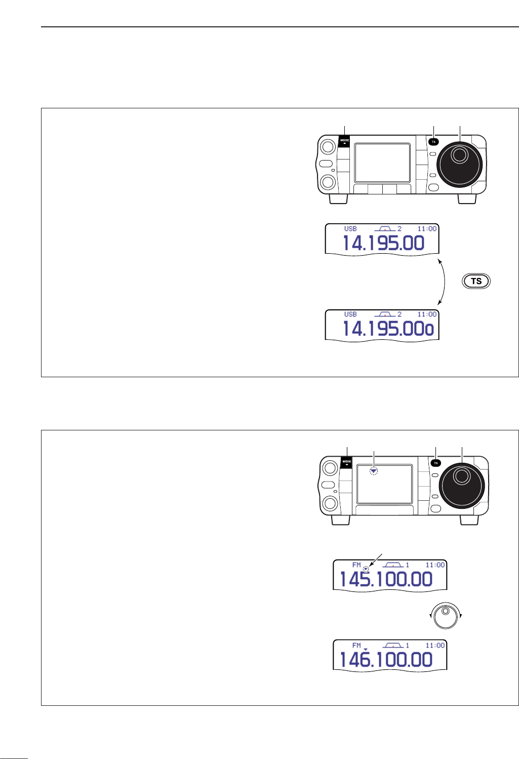
31
3BASIC OPERATION
When neither the quick tuning step or programmable
tuning step “
Z
” appear, rotating [DIAL] changes the
frequency in increments of 1 or 10 Hz. These tuning
steps are only available in SSB, CW and RTTY
modes.
qSelect SSB, CW or RTTY mode if necessary.
wPush and hold [TS] for 1 sec. to toggle between
the 1 Hz and 10 Hz step settings.
•When the 1 Hz step is selected, the 1 Hz digit appears
in the frequency indication; when the 10 Hz step is se-
lected, the 1 Hz digit disappears from the frequency in-
dication.
•Rotating [DIAL] changes the frequency in 1 Hz or 10Hz
tuning step.
Push and hold
for 1 sec.
Rotating [DIAL] changes the
frequency in 1 Hz steps.
Rotating [DIAL] changes the
frequency in 10 Hz steps.
[TS][MODE] [DIAL]
DSelecting 1 Hz or 10 Hz step (SSB/CW/RTTY only)
The quick tuning step function allows you to change
the frequency in 1 MHz steps when rotating [DIAL].
This function is only available in FM, WFM and AM
modes.
qSelect FM, WFM or AM mode if necessary.
wPush [TS] momentarily to toggle between the 1
MHz tuning step and the programmable tuning
step.
•“
Z
” appears above the 1 MHz indicator when the 1
MHz tuning step is selected.
•Rotating [DIAL] changes the frequency 1 MHz.
Quick tuning step indicator
Rotating [DIAL]
changes the frequency
in 1 MHz steps.
[TS][MODE] [DIAL]
Appears
D1 MHz quick tuning step (FM/WFM/AM only)
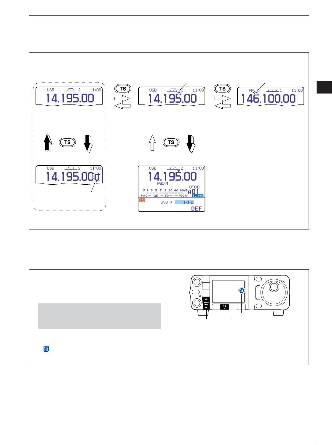
32
3
BASIC OPERATION
3
• [TS] switch flow chart
SSB/CW/RTTY modes Any mode FM/WFM/AM modes
1 Hz tuning
10 Hz tuning momentarily momentarily 1 MHz tuning
Programmable step tuning
(100 Hz –100 kHz)
momentarily
PushPush
Push Push
1 sec.1 sec.
1 sec.
Selectable for each mode.
Appears Appears
Appears
D1⁄4tuning function (CW/RTTY only)
While operating in CW/RTTY, the 1⁄4tuning function is
available for critical tuning. Dial sensitivity is reduced
to 1⁄4of normal when the 1⁄4function is in use.
qSelect M
-
3.
wPush [F-2 1/4]to toggle the 1⁄4function ON and
OFF.
• “ ” indication appears when the function is in
use.
[MENU/GRP] [F-2]
Appears
•Push and hold [MENU/GRP] for 1 sec. once or twice
to select the menu group M.
•Push [MENU/GRP] momentarily one or more times to
select the menu M
-
3.
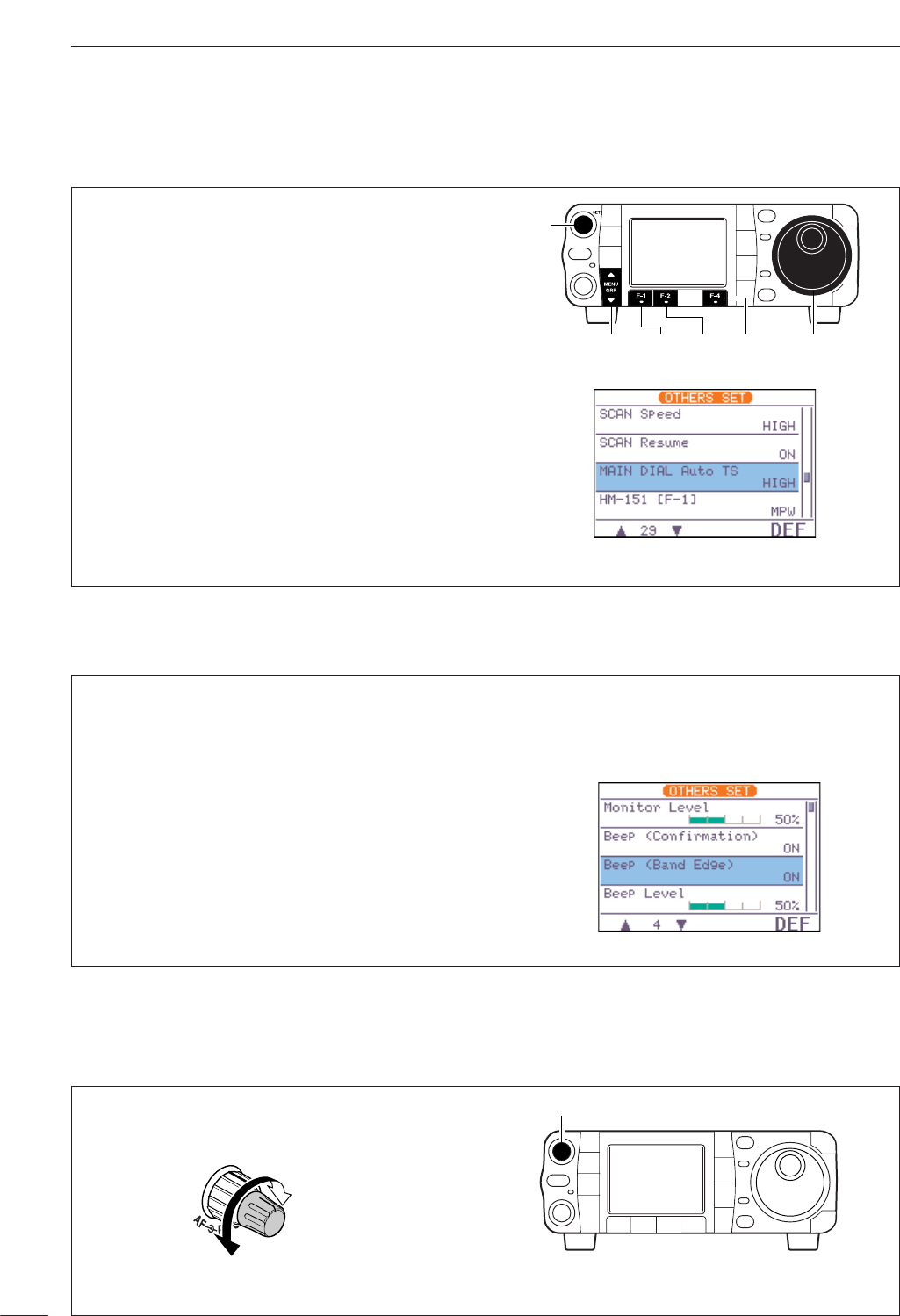
33
3BASIC OPERATION
■Volume setting
Rotate [AF] control clockwise to increase; counter-
clockwise to decrease the audio output level.
• Set a suitable audio level.
[AF]
Audio outut
decreases
Audio output
increases
DBand edge warning beep
When selecting a frequency that lies outside of a
band’s specified frequency range, a warning beep
sounds.
This function can be turned OFF in set mode, if de-
sired.
qEnter the miscellaneous (others) set mode as
above.
wPush [F-1 ≤]or [F-2 ≥]to select “Beep (Band
Edge),” then rotate [DIAL] to select the desired
setting.
•Push [F-4 DEF]for 1 sec. to return to default setting.
ePush [Z(
MENU
/
GRP
)] twice to return the normal op-
erating mode.
DAuto tuning step function
When rotating the tuning dial rapidly, the tuning speed
accelerates automatically as selected.
qPush [AF(
SET
)] momentarily to enter the set mode
menu.
wPush [F-4 OTH]to enter the miscellaneous (oth-
ers) set mode.
ePush [F-1 ≤]or [F-2 ≥]to select “MAIN DIAL
Auto TS.”
rRotate [DIAL] to select the desired tuning speed
from high, low and OFF.
•HIGH: Approx. 5 times faster
•LOW : Approx. twice faster
•OFF : Auto tuning step is turned OFF
•Push [F-4 DEF]for 1 sec. to return to default setting.
tPush [Z(
MENU
/
GRP
)] twice to return to the normal
operating mode.
[DIAL][MENU/GRP]
[AF]
[F-1] [F-2] [F-4]
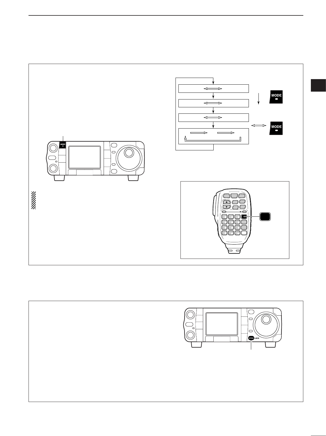
34
3
BASIC OPERATION
3
■Operating mode selection
The following modes are available in the IC-7000:
SSB (LSB/USB), CW, CW-R (CW reverse), RTTY,
RTTY-R (RTTY reverse), AM, FM and WFM (receive
only).
To select the desired mode of operation, push
[MODE] one or more times, then push [MODE] for
1 sec., if necessary. See the diagram at right for the
order of selection.
• The selected mode is indicated in the function display.
NOTE:
If a desired mode cannot be selected, it
may be hidden because of a setting in the miscel-
laneous (others) set mode (p. 136).
SPCH
/LOCK
TUNER
/CALL XFC
V/M
F-1 F-2
FIL
MODE
GENE
MW
123
456
789
.0CE
F-INP
ENT
1.8 3.5 7
10 14 18
21 24 28
50 144 430
HM-151
MODE
OPERATING MODE SELECTION
Push
momentarily
Push and hold
for 1 sec.
USB LSB
AM FM WFM
CW CW-R
RTTY-R
RTTY
[MODE]
■Voice synthesizer function
The IC-7000 has a voice synthesizer function. This
function announces the S-meter level, operating fre-
quency and mode (S-meter level’s announcement
can be deactivated—p. 134) in a clear, electronically
generated voice, in English (or Japanese).
qSelect the desired parameters to be announced,
such as Audio level, speed, language, contents, in
the miscellaneous (others) set mode. (p. 134)
wPush [SPCH/LOCK] momentarily to announce the
selected contents.
•Push [SPCH/LOCK] momentarily to stop the an-
nouncement.
[SPCH/LOCK]
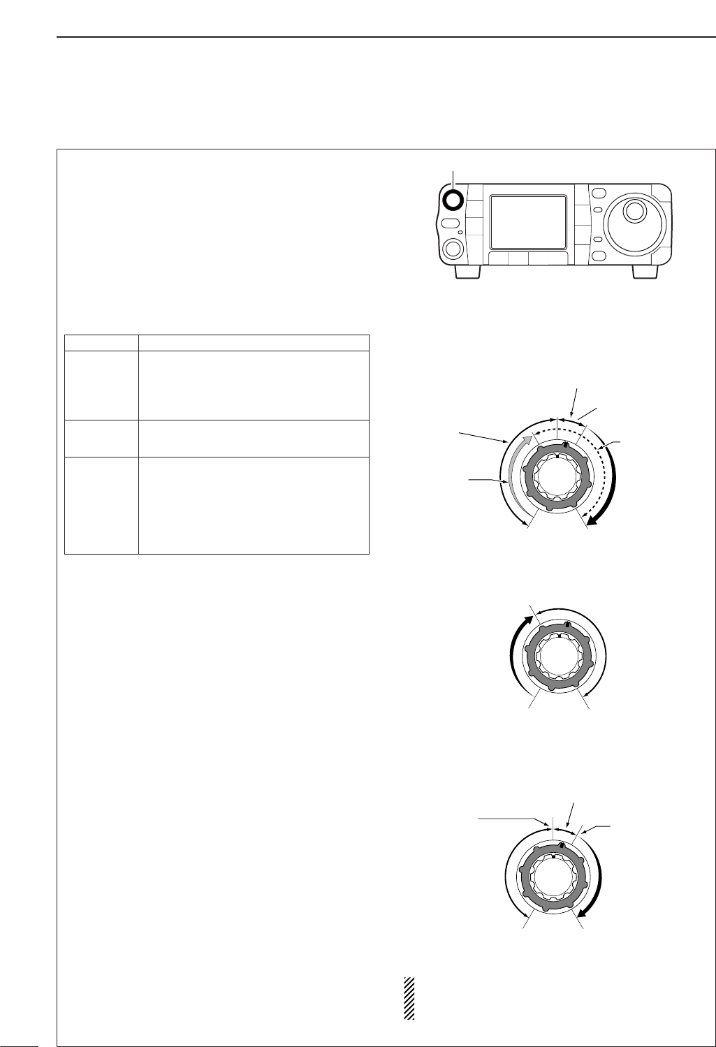
35
3BASIC OPERATION
■Squelch and receive (RF) sensitivity
Adjusts the RF gain and squelch threshold level. The
squelch removes noise output from the speaker
(closed position) when no signal is received.
• The squelch is particularly effective for FM. It is also avail-
able for other modes.
•The 12 to 1 o’clock position is recommended for any set-
ting of the [RF/SQL] control.
•The control can be set as ‘Auto’ (RF gain control in SSB,
CW and RTTY; squelch control in AM, FM and WFM (RF
gain is fixed at maximum) in the miscellaneous (others)
set mode as follows (p. 131).
Adjusting RF gain (Receive sensitivity)
Normally, [RF/SQL] is set to the 11 o’clock position.
Rotate [RF/SQL] to the 11 o’clock position for maxi-
mum sensitivity.
• Rotating counterclockwise from the maximum position re-
duces sensitivity.
• The S-meter indicates receive sensitivity.
Adjusting squelch (Removing non-signal noise)
Rotate [RF/SQL] clockwise when receiving no signal,
until the noise just disappears.
•[RX] indicator light goes out.
• Rotating [RF/SQL] past the threshold point invokes the S-
meter squelch—this allows you to set a minimum signal
level needed to open the squelch.
• When setting as RF gain/squelch control
•When functioning as RF gain control
(Squelch is fixed open; SSB, CW, RTTY only)
•When functioning as squelch control (RF gain is
fixed at maximum)
While rotating the RF gain control, noise may be
heard. This comes from the DSP unit and does not
indicate an equipment malfunction.
Squelch is
open.
S-meter
squelch
S-meter squelch
threshold
Noise squelch
threshold
(FM/WFM mode)
Lowest threshold Highest threshold
Noise squelch (FM/WFM mode)
Minimum RF gain
Adjustable
range
Maximum RF gain
Recommended level
RF gain
adjustable
range
Maximum
RF gain
S-meter shows
squelch level
Noise squelch (FM/WFM mode)
Squelch is
open.
[RF/SQL]
SETTING OPERATION
RF+SQL
Can be used in all modes.
(default)
Functions as noise squelch or S-meter
squelch in AM, FM and WFM modes;
S-meter squelch only in other modes.
SQL Operates as a squelch control.
• RF gain is fixed at maximum sensitivity.
Operates as an RF gain control in
SSB, CW and RTTY modes.
AUTO •Squelch is fixed open.
Operates as a squelch control in AM,
FM and WFM modes.
• RF gain is fixed at maximum sensitivity.
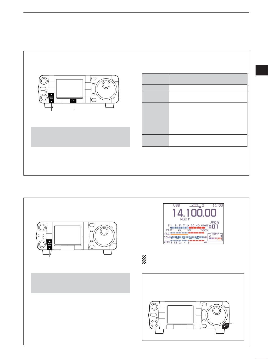
DMulti-function meter
36
3
BASIC OPERATION
3
■Meter function
The transceiver has 4 transmit meter functions for
your convenience. Select the desired meter with the
[F-3 MET]in the S
-
1display.
qSelect S
-
1.
wPush [F-3 MET]one or more times to select from
RF power (Po), SWR, ALC or compression level
(COM).
•The display indication changes as the table at the right.
•Push and hold [MENU/GRP] for 1 sec. once or twice
to select the menu group S.
•Push [MENU/GRP] momentarily one or more times to
select the menu S
-
1.
[MENU/GRP] [F-3]
DISPLAY MEASUREMENT
INDICATION
Po
Indicates the relative RF output power in %.
SWR Indicates the SWR on the transmission
line.
ALC
Indicates the ALC level. When the meter
movement shows the input signal level ex-
ceeds the allowable level, the ALC limits
the RF power. In such cases, reduce the
MIC gain setting (see p. 38) in the quick
set mode.
COM Indicates the compression level when the
speech compressor is in use.
In addition, the transceiver can display the multi-func-
tion meter in the graphic display, which displays all
transmit meters simultaneously.
➥Select G
-
2(Multi-meter).
The multi-function meter displays the internal tem-
perature meter for your reference.
•Push and hold [MENU/GRP] for 1 sec. once or twice
to select the menu group G.
•Push [MENU/GRP] momentarily one or more times to
select the menu G
-
2(Multi-meter).
[MENU/GRP]
Quick entry
➥Push [Z(
BAND
)] for 1 sec. to turn the multi-
function meter ON and OFF.
•Push [Z(
MENU
/
GRP
)] also to turn OFF.
[Z]
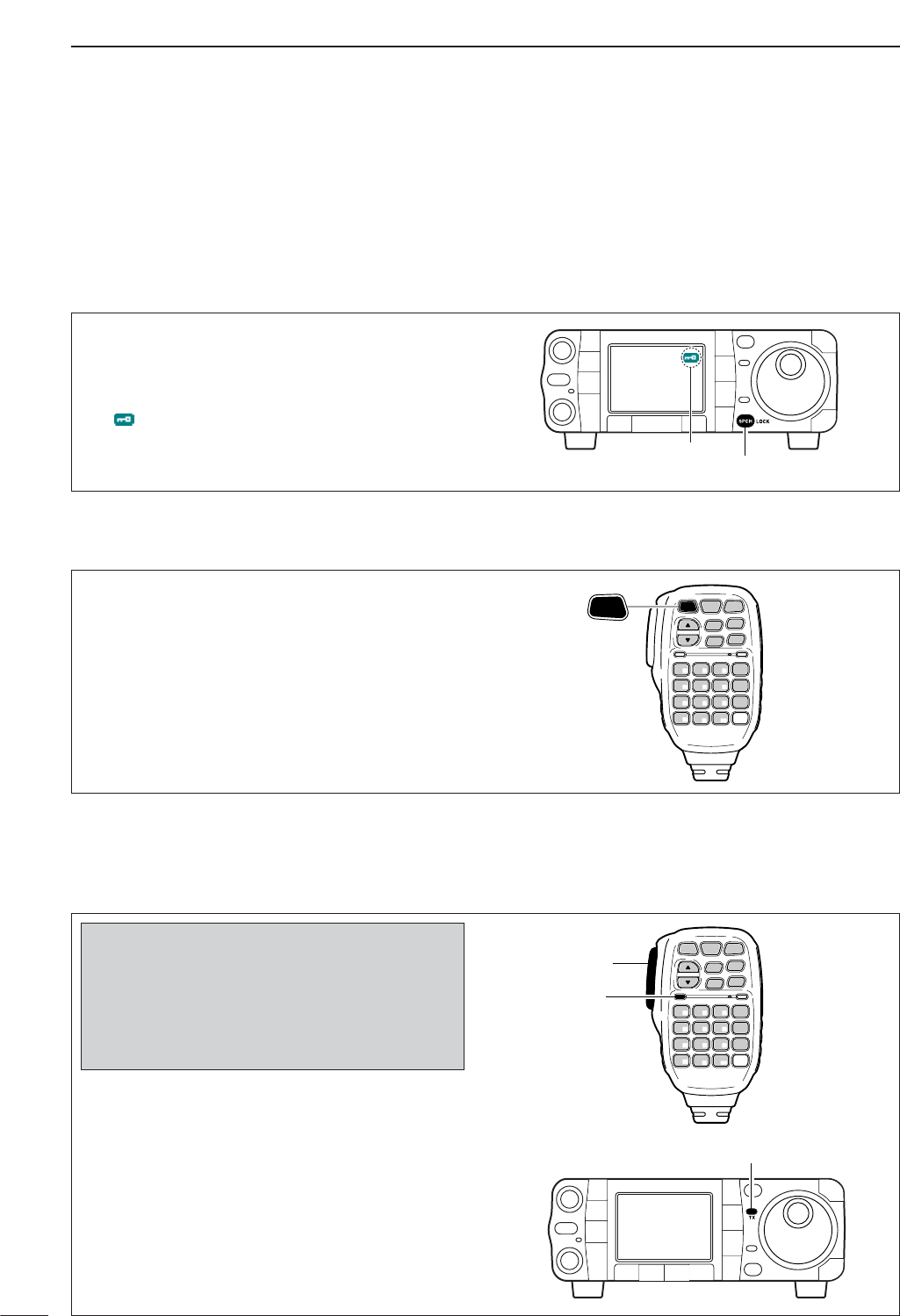
■Basic transmit operation
DTransmitting
37
3BASIC OPERATION
qPush [PTT] (microphone) to transmit.
•[TX] indicator lights red.
wRelease [PTT] (microphone) to return to receive.
[TX] indicator
SPCH
/LOCK
TUNER
/CALL XFC
V/M
F-1 F-2
FIL
MODE
GENE
MW
123
456
789
.0CE
F-INP
ENT
1.8 3.5 7
10 14 18
21 24 28
50 144 430
[PTT]
[TX]
HM-151
Before transmitting, monitor your selected op-
erating frequency to make sure transmitting
won’t cause interference to other stations on
the same frequency. It’s good Amateur practice
to listen first, and then, even if nothing is heard,
ask “is the frequency in use” once or twice, be-
fore you begin operating on that frequency.
DMicrophone lock function
This function locks microphone keypads.
➥Push [SPCH/LOCK] (microphone) for 1 sec. to
toggle the microphone lock function ON and OFF.
• “MIC LOCK ON” and “MIC LOCK OFF,” popup indica-
tors appear, respectively
•[PTT] and [SPCH/LOCK] can be used.
• All keys on the transceiver can be used.
SPCH
/LOCK
TUNER
/CALL XFC
V/M
F-1 F-2
FIL
MODE
GENE
MW
123
456
789
.0CE
F-INP
ENT
1.8 3.5 7
10 14 18
21 24 28
50 144 430
HM-151
SPCH
/LOCK
■Lock functions
The dial lock function prevents accidental change
caused by [DIAL].
➥Push [SPCH/LOCK] for 1 sec. to turn the dial lock
function ON and OFF.
•“ ” indicator appears while the dial lock function is
activated.
[SPCH/LOCK]
Appears
DDial lock function
The lock function can only be activated when display-
ing frequency, not in set mode, memory channel list-
ing, or TV display.
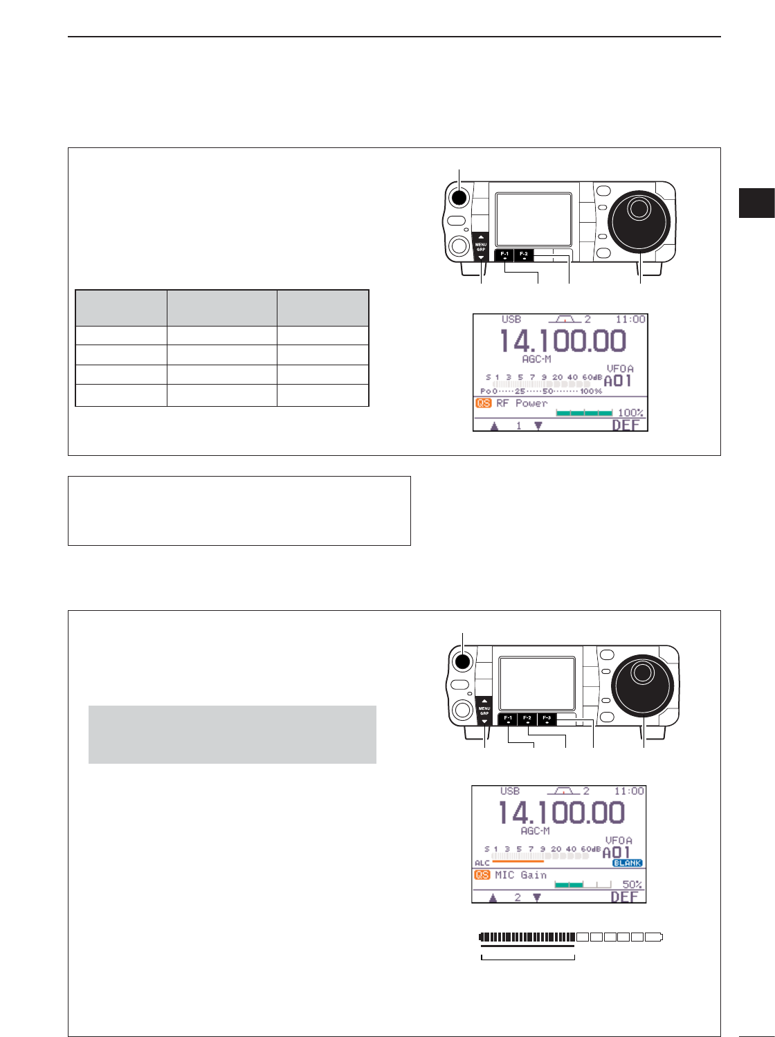
38
3
BASIC OPERATION
3
qPush [AF(
SET
)] momentarily to enter the set mode
menu.
wPush [F-1 QS]to enter the quick set mode.
ePush [F-1 Y]or [F-2 Z]to select “RF Power.”
rRotate [DIAL] to set the desired output setting.
•Output power is displayed in 1% steps (0% to 100%).
tPush [Z(
MENU
/
GRP
)] to exit quick set mode.
•Available power
*Carrier power
[MENU/GRP] [F-2][F-1] [DIAL]
[AF]
DSetting output power
Microphone gain must be adjusted properly so that
your signal does not distort when transmitted.
qSelect SSB or another phone mode (AM or FM
mode).
wSelect S
-
1.
ePush [F-3 MET]one or more times to select the
ALC meter.
•“ALC” appears.
rPush [AF(
SET
)] momentarily to enter the set mode
menu.
tPush [F-1 QS]to enter the quick set mode.
yPush [F-1 Y]or [F-2 Z]to select “MIC Gain.”
uPush [PTT] (microphone) to transmit.
•Speak into the microphone at your normal voice level.
iWhile speaking into the microphone, rotate [DIAL]
so that the ALC meter reading does not go outside
the ALC zone.
• Microphone gain is adjusted in 1% steps (0% to 100%).
oRelease [PTT] (microphone) to return to receive.
!0 Push [Z(
MENU
/
GRP
)] to exit the quick set mode.
•Push [Z(
MENU
/
GRP
)] again to return the normal oper-
ating mode.
ALC zone
ALC
[MENU/GRP] [F-3][F-1] [F-2] [DIAL]
[AF]
•Push and hold [MENU/GRP] for 1 sec. once or twice
to select the menu group S.
•Push [MENU/GRP] momentarily one or more times to
select the menu S
-
1.
DSetting microphone gain
BAND SSB/CW AM*
RTTY/FM
HF 2–100 W 1–40 W
50 MHz 2-100 W 1–40 W
144 MHz 2–50 W 2–20 W
430 MHz 2–35 W 2–14 W
If a linear amplifier is connected such as the IC-PW1/EURO,
set the output power using the ALC meter (see below) to the
ALC zone (ALC meter reading should be within this zone),
otherwise the linear amplifier will not work properly.
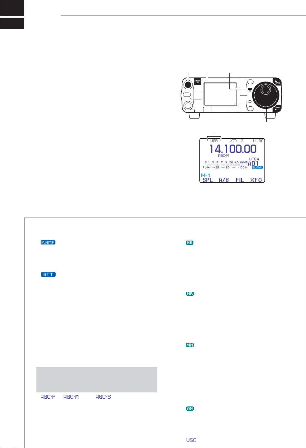
DConvenient functions for receive
4
39
RECEIVE AND TRANSMIT
■Operating SSB
qPush [Y(
BAND
)]/[Z(
BAND
)] to select the desired
band or push a band key on the HM-151.
wPush [MODE] momentarily or push and hold for
1 sec. to select LSB or USB mode.
•Below 10 MHz LSB is automatically selected; above
10 MHz USB is automatically selected.
eRotate [DIAL] to tune in a desired signal.
•The S-meter indicates received signal strength when
signal is received.
rRotate [AF] to set audio to a comfortable listening
level.
tPush [PTT] (microphone) to transmit.
•[TX] indicator lights red.
ySpeak into the microphone at your normal voice
level.
• Adjust ‘MIC Gain’ at this step, if necessary. (p. 38)
uRelease [PTT] (microphone) to return to receive.
“LSB” or “USB” appears
[Y]
[Z]
[DIAL]
[MODE][AF] [TX] indicator
• Preamp and attenuator (p. 74)
➥Push [P.AMP/ATT] momentarily to tune the pre-
amp ON or OFF.
• “ ” appears when the preamp is set to ON.
➥Push [P.AMP/ATT] for 1 sec. to turn the attenua-
tor ON.
•Push [P.AMP/ATT] momentarily to turn the attenuator
OFF.
• “ ” appears when the attenuator is set to ON.
• Twin PBT (passband tuning) (p. 79)
➥Push [PBT/M-ch/RIT] (switch) momentarily once
or twice to select the twin PBT ON or OFF (M-ch
RIT).
•PBT indicator lights green when the twin PBT is se-
lected.
➥Rotate [PBT/M-ch/RIT] (controls–inner/outer).
•Push [PBT/M-ch/RIT(
CLR
)] to clear the settings.
• AGC (auto gain control) (p. 76)
➥While “M
-
3” is selected, push [F-3 AGC]momen-
tarily one or more times to select AGC fast, AGC
middle and AGC slow.
•“ ,” “ ” and “ ” appears when the
fast time constant, middle time constant and slow
time constant is selected, respectively.
➥While “M
-
3” is selected, push [F-3 AGC]for 1
sec. to enter the AGC set mode.
•Push [F-2 FAST],[F-3 MID]or [F-4 SLOW]to select
the time constant, then rotate [DIAL] to adjust the time
constant.
• Noise blanker (p. 80)
➥Push [NB/ADJ] to turn the noise blanker ON and
OFF.
• “ ” appears when the noise blanker is set to ON.
➥Push [NB/ADJ] for 1 sec. to enter the noise
blanker set mode, then rotate [DIAL] to adjust the
threshold level, or noise pulse width.
• DSP noise reduction (p. 81)
➥Push [NR/LEV] to turn the DSP noise reduction
ON and OFF.
• “ ” appears when the DSP noise reduction is ON.
➥Push [NR/LEV] for 1 sec. to enter the DSP noise
reduction level set mode, then rotate [DIAL] to
adjust the DSP noise reduction level.
• Manual notch filter (pgs. 82, 83)
➥Push [MNF/ADJ] to turn the manual notch filter
ON and OFF.
• “ ” appears when the manual notch filter is set to ON.
➥Push [MNF/ADJ] for 1 sec. to enter the manual
notch filter set mode.
•Push [F-2 NF1],[F-3 NF2]to select the notch filter,
push [F-4 NW]to set the filter width, rotate [DIAL] to
set the notch frequency.
• Auto notch filter (p. 82)
➥Push [ANF/•REC] to turn the auto notch filter ON
and OFF.
• “ ” appears when the auto notch filter is set to ON.
• VSC (voice squelch control) (p. 84)
➥While “S
-
1” is selected, push [F-4 VSC]to turn
the VSC function ON and OFF.
•“”appears when VSC function is set to ON.
•Push and hold [MENU/GRP] for 1 sec. once or twice
to select the menu group M.
•Push [MENU/GRP] momentarily one or more times
to select the menu M
-
3.
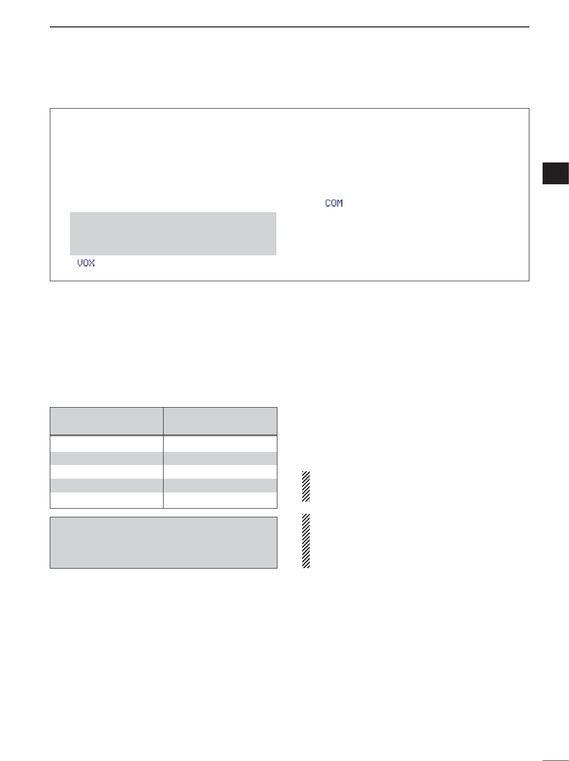
40
4
RECEIVE AND TRANSMIT
4
DConvenient functions for transmit
• Transmit quality monitor (p. 89)
➥Push [AF(
SET
)], then [F-4 OTH]to enter the mis-
cellaneous (others) set mode. Select an item with
[F-1 ≤]/[F-2 ≥], then rotate [DIAL] to turn the
monitor function ON and OFF.
• VOX (voice operated transmit) (p. 85)
➥While “M
-
3” is selected, push [F-1 VOX]to turn
the VOX function ON and OFF.
• “ ” appears when the VOX function is set to ON.
➥While “M
-
3” is selected, push [F-1 VOX]for 1
sec. to enter the VOX set mode.
•Push [F-1 ≤]/[F-2 ≥]to select an item.
•Rotate [DIAL] to set the value/conditions.
• Speech compressor (p. 89)
➥While “M
-
3” is selected, push [F-2 COM]to turn
the speech compressor ON and OFF.
•“”appears when the speech compressor is set to
ON.
➥While “M
-
3” is selected, push [F-2 COM]for 1
sec. to enter the compression level set mode.
•Rotate [DIAL] to adjust the compression level.
•Push and hold [MENU/GRP] for 1 sec. once or twice
to select the menu group M.
•Push [MENU/GRP] momentarily one or more times
to select the menu M
-
3.
DAbout 5 MHz band operation (USA version only)
Operation on the 5 MHz band is allowed on 5 discrete
frequencies and must adhere to the following:
• USB mode
• Maximum of 50 watts ERP (Effective Radiated Power)
• 2.8 kHz bandwidth
It is the operator’s responsibility to set all controls so
that the transmission in this band meets the stringent
conditions under which we may use these frequencies.
NOTE: We recommend that you store these fre-
quencies, mode and filter settings into the memory
channel for easy recall.
*The channel center frequencies that are specified
by the FCC, show the center frequency of their
passband. However, the IC-7000 displays carrier
point frequency, so set 1.5 kHz below from FCC
channel center frequency.
IC-7000 Tuning FCC Channel
Frequency* Center Frequency*
5.33050 MHz 5.33200 MHz
5.34650 MHz 5.34800 MHz
5.36650 MHz 5.36800 MHz
5.37150 MHz 5.37300 MHz
5.40350 MHz 5.40500 MHz
To assist you in operating the 5 MHz band correctly
within the rules specified by the FCC, transmission
is impossible on any 5 MHz band frequency other
than the 5 frequencies indicated in the table above.
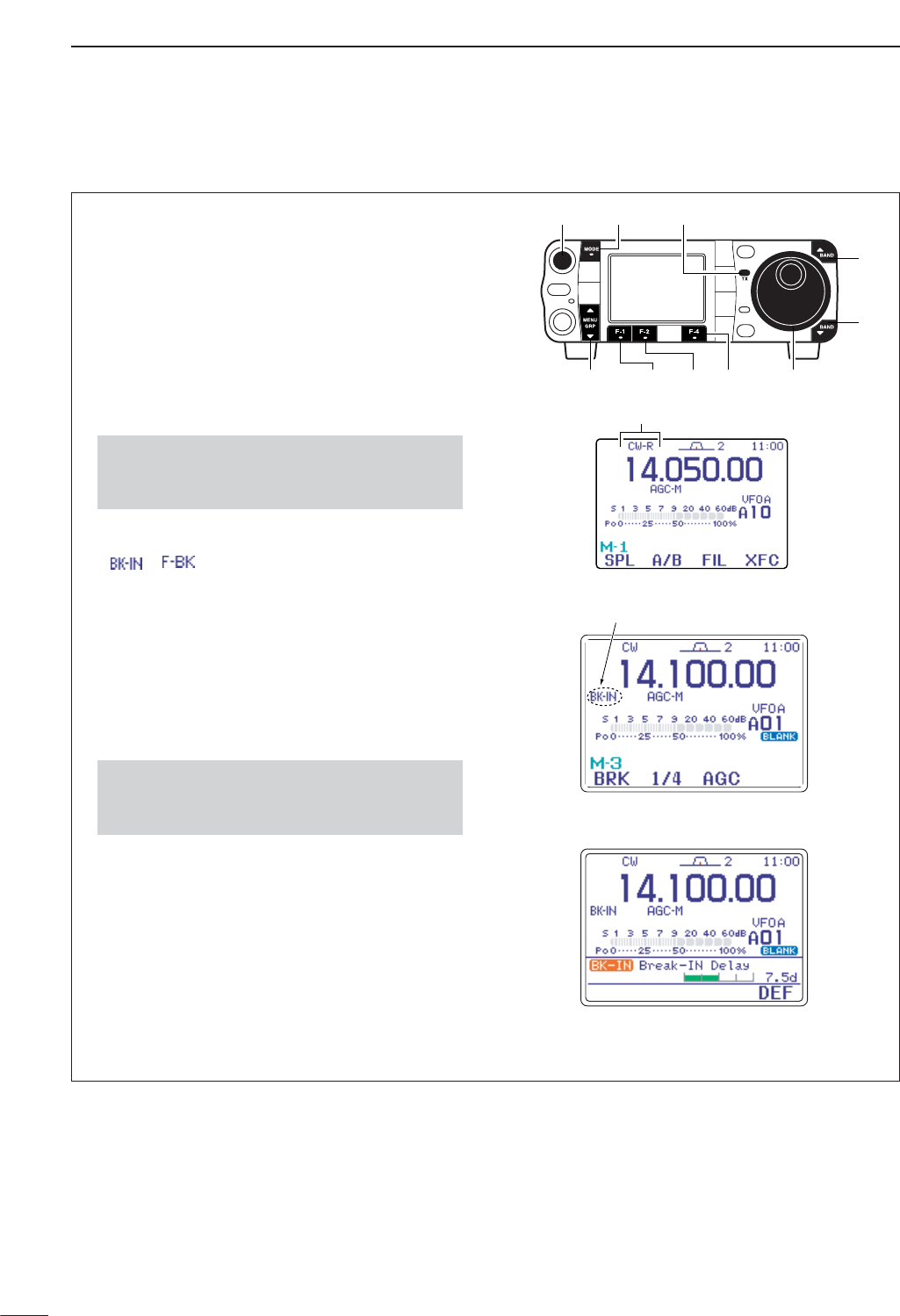
41
4RECEIVE AND TRANSMIT
■Operating CW
qConnect a paddle or straight key as on page 22.
wPush [Y(
BAND
)]/[Z(
BAND
)] to select the desired
band or push a band key on the HM-151.
ePush [MODE] momentarily to select CW mode.
•After CW mode is selected, push [MODE] for 1 sec. to
toggle between CW and CW-R modes.
rRotate [DIAL] to tune in a desired signal with the
desired tone frequency.
tRotate [AF] to set audio to a comfortable listening
level.
ySet CW break-in operation as semi break-in, full
break-in or OFF.
•Push [F-1 BRK]one or more times to select the CW
break-in operation.
•“,” “,” and “OFF (no indication)” appears.
➧BK-IN: semi break-in
➧F-BK : full break-in
➧OFF : no break-in (ACC socket connection is neces-
sary as shown on page 22.)
uSet the CW delay time when semi break-in opera-
tion is selected.
•Push [F-1 BRK]for 1 sec. to enter the break-in delay
time set mode.
•Rotate [DIAL] to set the desired delay time.
iSet CW setting in the keyer set mode (S
-
1).
•Push [F-2 KEY],[Z(
MENU
/
GRP
)], then [F-4 SET]to
enter the keyer set mode. (p. 49)
oKeying to transmit, use the electric keyer or paddle
to send your CW signals.
•[TX] indicator lights red.
• The Po meter indicates transmitted CW signal strength.
!0 Stop keying to return to receive.
Delay time of 7.5 dots is selected
for semi break-in operation.
Semi break-in operation is selected.
Appears
“CW” or “CW-R” appears
[Y]
[Z]
[DIAL]
[MODE][AF] [TX] indicator
[MENU/GRP] [F-4][F-1] [F-2]
•Push and hold [MENU/GRP] for 1 sec. once or twice
to select the menu group S.
•Push [MENU/GRP] momentarily one or more times to
select the menu S
-
1.
•Push and hold [MENU/GRP] for 1 sec. once or twice
to select the menu group M.
•Push [MENU/GRP] momentarily one or more times to
select the menu M
-
3.
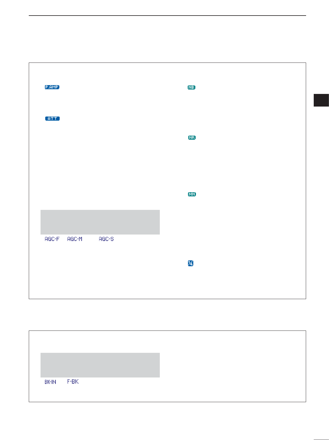
42
4
RECEIVE AND TRANSMIT
4
DConvenient functions for receive
• Preamp and attenuator (p. 74)
➥Push [P.AMP/ATT] momentarily to turn the pre-
amp ON or OFF.
• “ ” appears when the preamp is set to ON.
➥Push [P.AMP/ATT] for 1 sec. to turn the attenua-
tor ON.
•Push [P.AMP/ATT] momentarily to turn the attenuator
OFF.
• “ ” appears when the attenuator is set to ON.
• Twin PBT (passband tuning) (p. 79)
➥Push [PBT/M-ch/RIT] (switch) momentarily once
or twice to select the twin PBT ON or OFF (M-ch
RIT).
•PBT indicator lights green when the twin PBT is se-
lected.
➥Rotate [PBT/M-ch/RIT] (controls–inner/outer).
•Push [PBT/M-ch/RIT(
CLR
)] to clear the settings.
• AGC (auto gain control) (p. 76)
➥While “M
-
3” is selected, push [F-3 AGC]momen-
tarily one or more times to select AGC fast, AGC
middle and AGC slow.
•“ ,” “ ” and “ ” appears when the
fast time constant, middle time constant and slow
time constant is selected, respectively.
➥While “M
-
3” is selected, push [F-3 AGC]for 1
sec. to enter the AGC set mode.
•Push [F-2 FAST],[F-3 MID]or [F-4 SLOW]to select
the time constant, then rotate [DIAL] to adjust the time
constant.
• Noise blanker (p. 80)
➥Push [NB/ADJ] to turn the noise blanker ON and
OFF.
• “ ” appears when the noise blanker is set to ON.
➥Push [NB/ADJ] for 1 sec. to enter the noise
blanker set mode, then rotate [DIAL] to adjust the
threshold level, or noise pulse width.
• DSP noise reduction (p. 81)
➥Push [NR/LEV] to turn the DSP noise reduction
ON and OFF.
• “ ” appears when the DSP noise reduction is set to
ON.
➥Push [NR/LEV] for 1 sec. to enter the noise re-
duction level set mode, then rotate [DIAL] to ad-
just the DSP noise reduction level.
• Manual notch filter (pgs. 82, 83)
➥Push [MNF/ADJ] to turn the manual notch filter
ON and OFF.
•“ ” appears when the manual notch filter is set to
ON.
➥Push [MNF/ADJ] for 1 sec. to enter the manual
notch filter set mode.
•Push [F-2 NF1],[F-3 NF2]to select the notch filter,
push [F-4 NW]to set the filter width, rotate [DIAL] to
set the attenuating frequency.
•1⁄4function (p. 32)
➥While “M
-
3” is selected, push [F-2 1/4]to turn
the 1⁄4function ON and OFF.
• “ ” indicator appears when the function is activate.
•Push and hold [MENU/GRP] for 1 sec. once or twice
to select the menu group M.
•Push [MENU/GRP] momentarily one or more times
to select the menu M
-
3.
• Break-in function (p. 87)
➥While “M
-
3” is selected, push [F-1 BRK]one or
more times to select the CW break-in operation.
•“ ” or “ ” appears when the semi break-in or
full break-in is set to ON, respectively.
• Memory keyer function (p. 45)
➥While “S
-
1” is selected, push [F-2 KEY]to enter
the keyer set memu.
•Push and hold [MENU/GRP] for 1 sec. once or twice
to select the menu group M.
•Push [MENU/GRP] momentarily one or more times
to select the menu M
-
3.
DConvenient functions for transmit
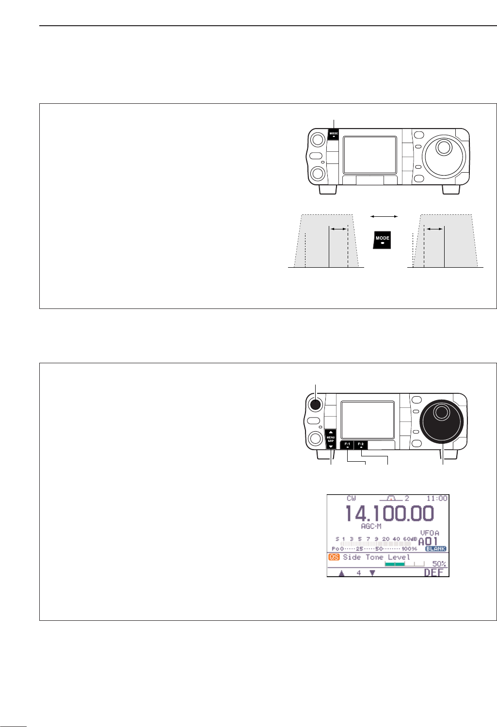
43
4RECEIVE AND TRANSMIT
DCW reverse mode
The CW-R (CW Reverse) mode receives CW signals
on the reverse sideband like that of LSB and USB
modes.
Use when interference is near the desired signal and
you want to change the interference tone.
qPush [MODE] several times to select CW mode.
w
Push [MODE] for 1 sec. to select CW or CW-R
mode.
•Check the interference tone.
• Receive audio tone response
CW-R mode (USB side)CW mode (LSB side)
BFO
600 Hz
signal
inteference signal
600 Hz
BFO
inteference
Push
for 1 sec.
[MODE]
DCW side tone function
When the transceiver is in receive condition (and the
break-in function is OFF— p. 87) you can listen to the
tone of your CW signal without actually transmitting.
This allows you to match your transmit signal exactly
to another station’s. This also convenient for CW
practice.
qWhen CW (CW-R) mode is selected, enter the
quick set mode.
•Push [AF(
SET
)] momentarily to enter the set mode
menu.
•Push [F-1 QS]to enter the quick set mode.
wPush [F-1 ≤]or [F-2 ≥]several times to select
“Side Tone Level,” then rotate [DIAL] to ad-
just the side tone level.
•Side tone level is adjusted in 1% steps (0% to 100%).
ePush [Z(
MENU
/
GRP
)] to exit the quick set mode.
•Push [Z(
MENU
/
GRP
)] again to return the normal oper-
ating mode.
[DIAL][MENU/GRP] [F-1] [F-2]
[AF]
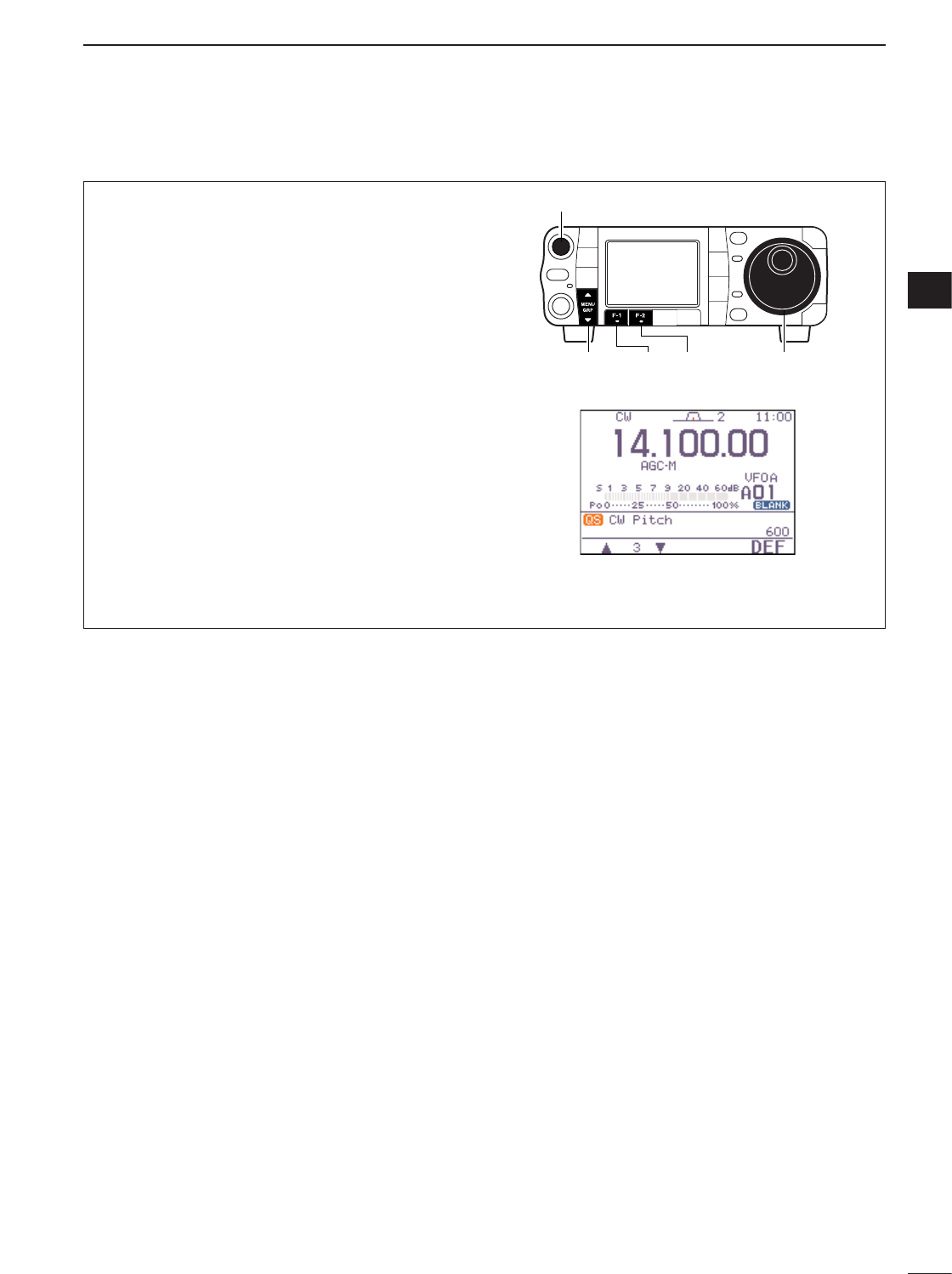
44
4
RECEIVE AND TRANSMIT
4
DCW pitch control
The received CW audio pitch and monitored CW
audio pitch can be adjusted to suit your preferences
(300 to 900 Hz) without changing the operating fre-
quency.
qWhen CW (CW-R) mode is selected, enter the
quick set mode.
•Push [AF(
SET
)] momentarily to enter the set mode
menu.
•Push [F-1 QS]to enter the quick set mode.
wPush [F-1 ≤]or [F-2 ≥]several times to select “CW
Pitch,” then rotate [DIAL] to set the desired
pitch.
•CW pitch is adjusted in 5 Hz steps (300 to 900 Hz).
ePush [Z(
MENU
/
GRP
)] to exit the quick set mode.
•Push [Z(
MENU
/
GRP
)] again to return the normal oper-
ating mode.
•This shows the default setting for the CW pitch control
(600 Hz).
[DIAL][MENU/GRP] [F-1] [F-2]
[AF]
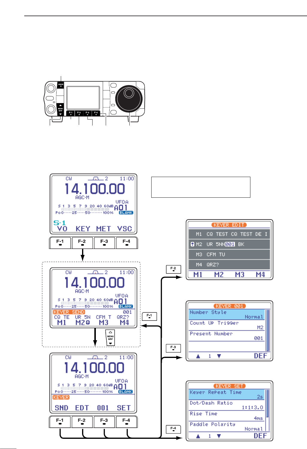
45
4RECEIVE AND TRANSMIT
■Electronic CW keyer
The IC-7000 has a number of convenient functions for
the electronic keyer that can be accessed from the
memory keyer menu.
qPush [MODE] to select CW mode.
wSelect S
-
1.
ePush [F-2 KEY]to enter the keyer send menu.
rPush [Z(
MENU
/
GRP
)] to select the keyer root menu.
tPush one of the multi-function keys ([F-1] to [F-4])
to select the desired menu. See the diagram below.
•Push [Z(
MENU
/
GRP
)] to return to the previous indica-
tion.
[MODE]
[DIAL][DIAL][MENU/GRP]
[F-1]
[F-2] [F-3] [F-4]
¡Memory keyer root menu
¡Memory keyer send menu
¡Memory keyer edit menu
¡Contest number set mode
¡Keyer set mode
Memory keyer root menu can also be set to
the starting menu for keyer operation in the
miscellaneous (others) set mode. (p.136)
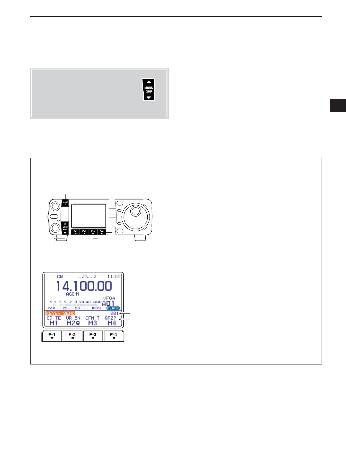
46
4
RECEIVE AND TRANSMIT
4
Pre-set characters can be sent using the memory
keyer send menu. Contents of the memory keyer are
set using the edit menu.
• Transmitting
qSelect CW mode with [MODE].
wSet the break-in function ON (p. 87).
•When step tis performed with the break-in function
OFF, the memory keyer contents are monitored.
eSelect S
-
1.
rPush [F-2 KEY]to enter the keyer send menu.
•If the keyer root menu appears, push [F-1 SND]. The
keyer starting menu can be changed in the miscella-
neous (others) set mode (p. 136).
tPush [F-1 M1]—[F-4 M4]momentarily to transmit
the contents one time; push these keys for 1 sec.
to transmit the contents repeatedly.
•“M1”– “M4” are highlighted while transmitting.
•“(” and “)” appear while transmitting repeatedly.
•While transmitting repeatedly, push any function key to
cancel the transmission.
•Set the repeat interval of the memory keyer to 1–60
sec. (1 sec. steps). See p. 49 for keyer set mode.
•To decrement the contact number, push
[Y(
MENU
/
GRP
)].
yPush [Z(
MENU
/
GRP
)] twice to exit the memory
keyer send menu and return to normal CW mode
indication.
• Memory keyer send menu
Memory keyer
content
Contact number
[MODE]
[MENU/GRP]
[F-1]
[F-2] [F-3] [F-4]
DMemory keyer send menu
Menu group selection
Push [MENU/GRP] for 1 sec.
Selection from:
M
,
S
or
G
(Graphic)
Menu selection (Example: S)
Push [MENU/GRP] momentarily.
Selection from:
S
-
1
,
S
-
2
or
S
-
3
Either
Y or Z
Either
Y or Z
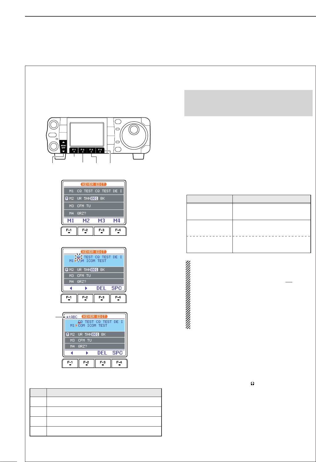
47
4RECEIVE AND TRANSMIT
DEditing a keyer memory
The contents of the memory keyer memories can be
set using the memory keyer edit menu. The memory
keyer can memorize and re-transmit 4 CW se-
quences for often-used CW sentences, contest num-
ber, etc. Total capacity of the memory keyer is 55
characters per memory channel.
• Pre-programmed contents
• Programming contents
qPush [MODE] to select CW mode.
wSelect S
-
1.
ePush [F-2 KEY]then [Z(
MENU
/
GRP
)] to select the
keyer root menu.
•If the keyer root menu appears, skip pushing
[Z(
MENU
/
GRP
)]. The keyer starting menu can be
changed in the miscellaneous (others) set mode.
rPush [F-2 EDT]to enter the keyer edit menu.
tPush [F-1 M1]—[F-4 M4]to select the desired
keyer memory channel.
yPush [Y(
MENU
/
GRP
)] several times to select the de-
sired character group ([ABC],[123] or [etc]).
•Selectable characters (with [DIAL]);
NOTE:
“^” is used to transmit a following word with no
space such as
AR
. Put “^” before a text string
such as ^AR, and the CW prosign “ ” is sent
with no space.
“✱” is used to insert the CW contest number.
The contest number automatically increments
by 1. This function is only available for one
memory keyer channel at a time. Memory
keyer channel M2 uses “✱” by default.
uSelect the desired character by rotating [DIAL] or
by pushing the band key (HM-151) for the incre-
menting trigger memory number input.
•Push [F-1 Å]or [F-2 Ç]for cursor movement.
•Push [F-3 DEL]to delete the selected character.
•Push [F-4 SPC]to input a space.
•“✱” is for contact numbers and can be input for the
count up trigger channel (“ ” appears).
iRepeat steps yand uuntil the desired contents
are input.
oPush [Z(
MENU
/
GRP
)] to return to memory channel
selection mode, then select the next memory chan-
nel and repeat steps yand ifor character input,
if desired.
!0 Push [Z(
MENU
/
GRP
)] twice to exit the keyer edit
mode.
AR
Key selection
ABC
Editable characters
A to Z (capital leters)
123
0 to 9 (numbers)
etc
/ ? ^. , @ ✽
•Push and hold [MENU/GRP] for 1 sec. once or twice
to select the menu group S.
•Push [MENU/GRP] momentarily one or more times to
select the menu S
-
1.
CH Contents
CQ TEST CQ TEST DE ICOM ICOM TEST
UR 5NN✽ BK
CFM TU
M1
M2
M3
QRZ?
M4
Memory channel select
Selected
character
[MENU/GRP]
[F-1]
[F-2] [F-3] [F-4]
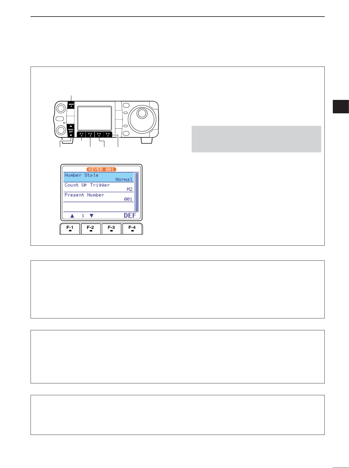
48
4
RECEIVE AND TRANSMIT
4
2Count UP Trigger
This selects which of the four memory channels will
have the contest serial number exchange. The count
up trigger increments the serial number automatically
after each complete serial number exchange is sent.
• M1, M2, M3 and M4 can be set. (default: M2)
1Number Style
This item sets the numbering system used for contest
(serial) numbers— normal or cut numbers.
Normal : Does not use morse cut number
(default)
190➜ANO: Sets 1 as A, 9 as N and 0 as O.
190➜ANT : Sets 1 as A, 9 as N and 0 as T.
90➜NO : Sets 9 as N and 0 as O.
90➜NT : Sets 9 as N and 0 as T.
3Present Number
This item shows the current number in the count up
trigger channel set above.
•Rotate [DIAL] to change the number, or push [F-4
CLR]for 1sec. to reset the current number to 001.
This menu is used to set the contest (serial) number
and incrementing trigger channel, etc.
• Setting the contact (serial) number
Contact number can be automatically transmitted
from one of the memory keyer channels. The Morse
cut numbers can be used as the contact numbers.
The maximum number for contact numbers is 9999.
qSelect CW mode with [MODE].
wSelect S
-
1.
ePush [F-2 KEY]then [Z(
MENU
/
GRP
)] to select the
keyer root menu.
rPush [F-3 001]to enter the contest number set
menu.
tPush [F-1 ≤]or [F-2 ≥]to select the desired set
item.
•Push [F-4 DEF]for 1 sec. to select the default condi-
tion or value.
yPush [Z(
MENU
/
GRP
)] twice to exit the contest num-
ber set menu and return to normal CW mode indi-
cation.
•Push and hold [MENU/GRP] for 1 sec. once or twice
to select the menu group S.
•Push [MENU/GRP] momentarily one or more times to
select the menu S
-
1.
[MODE]
[MENU/GRP]
[F-1]
[F-2] [F-3] [F-4]
DContest number set mode
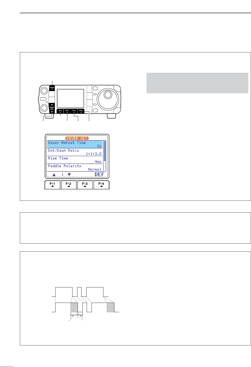
49
4RECEIVE AND TRANSMIT
This set mode is used to set the memory keyer repeat
time, dash weight, paddle specifications, keyer type,
etc.
• Setting the electronic keyer
qSelect CW mode with [MODE].
wSelect S
-
1.
ePush [F-2 KEY]then [Z(
MENU
/
GRP
)] to select the
keyer root menu.
rPush [F-4 SET]to enter the keyer set menu.
tPush [F-1 ≤]or [F-2 ≥]to select the desired set
item.
•Push [F-4 DEF]for 1 sec. to select the default condi-
tion or value.
yPush [Z(
MENU
/
GRP
)] twice to exit the keyer set
menu and return to normal CW mode indication.
•Push and hold [MENU/GRP] for 1 sec. once or twice
to select the menu group S.
•Push [MENU/GRP] momentarily one or more times to
select the menu S
-
1.
[MODE]
[MENU/GRP]
[F-1]
[F-2] [F-3] [F-4]
DKeyer set mode
1Keyer Repeat Time
When sending CW using the repeat timer, this item
sets the time between transmission.
•1 to 60 sec. in 1 sec. steps can be selected.
•Push [F-4 DEF]for 1 sec. to select a default setting.
(default: 2 sec.)
2Dot/Dash Ratio
This item sets the dot/dash ratio. • 1 : 1 : 2.8 to 1 : 1 : 4.5 can be set.
• Check the ratio with side tone in CW mode.
•Push [F-4 DEF]for 1 sec. to select a default ratio of
1:1:3.0.
Keying weight example: Morse code “K”
DASH
Weight setting:
1:1:3 (default)
Weight setting:
Adjusted
DASH
DOT (Fixed*)
Adjustable range SPACE (Fixed*)
*SPACE and DOT length can be adjusted with
“Key Speed” only in the quick set mode.
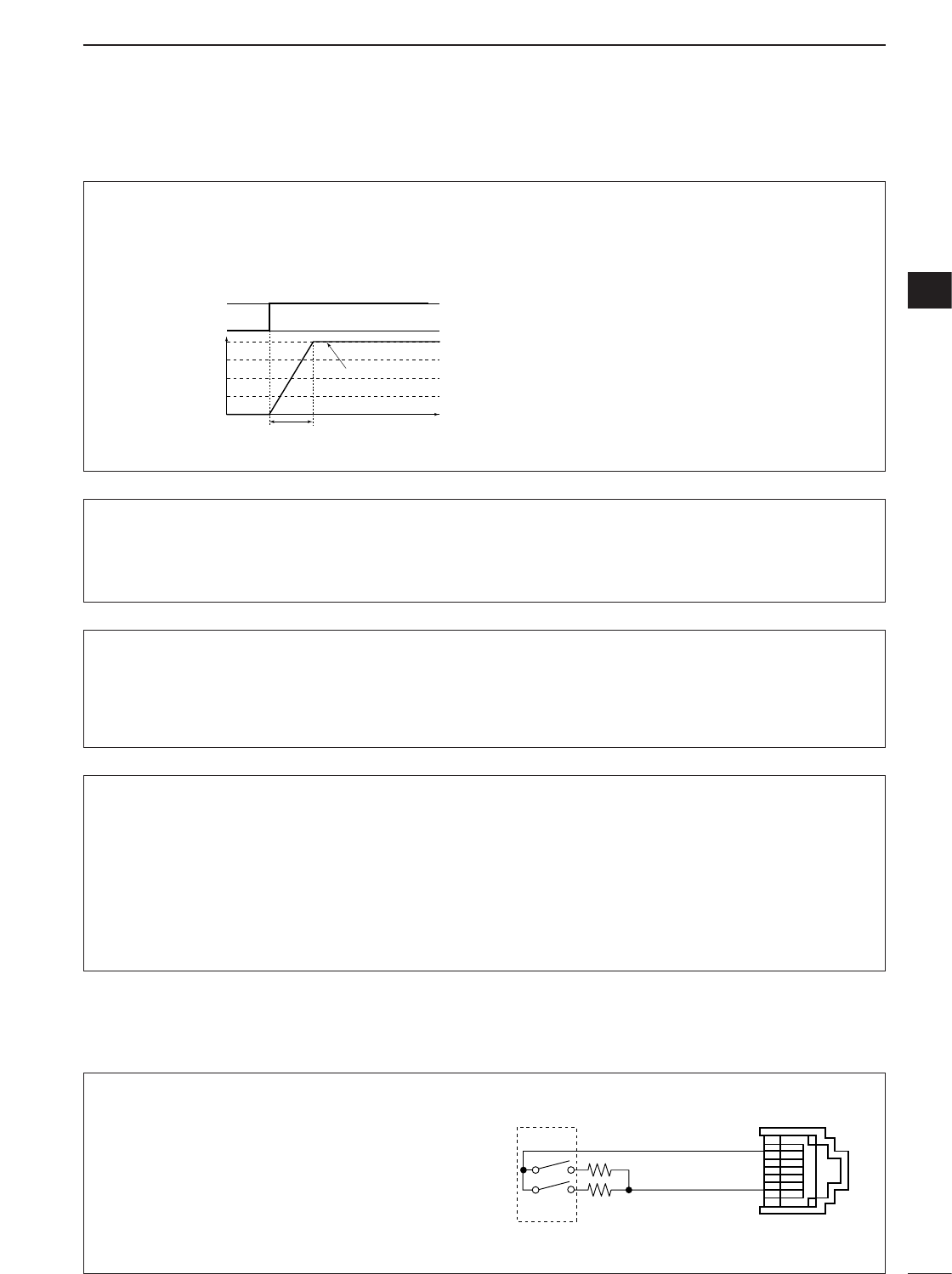
50
4
RECEIVE AND TRANSMIT
4
DKeyer set mode (continued)
3Rise Time
This item sets the envelop time period which the out-
put power becomes the set transmit power.
•2, 4, 6, or 8 msec. can be selected.
•Push [F-4 DEF]for 1 sec. to select a default setting.
(default: 4 sec.)
Key action
Tx output power
• About rise time
Rise time
Tx
Rx
Set Tx power level
Time
0
4Paddle Polarity
This item sets the paddle polarity. •Normal and reverse polarity can be selected.
•Push [F-4 DEF]for 1 sec. to select a default setting.
(default: Normal)
5Keyer Type
This item selects the keyer type for [KEY] connector
on the rear panel.
•ELEC-KEY, BUG-KEY and Straight key can be se-
lected.
•Push [F-4 DEF]for 1 sec. to select a default setting.
(default: ELEC-KEY)
6MIC U/D Keyer (HM-103)
(Microphone’s [UP]/[DN] switches keyer)
This item allows you to set the microphone [UP]/[DN]
switches to be used as a paddle.
•ON : [UP]/[DN] switches can be used for CW.
•OFF: [UP]/[DN] switches cannot be used for CW.
•Push [F-4 DEF]for 1 sec. to select a default setting.
(default: OFF)
NOTE: When “ON” is selected, the frequency and
memory channel cannot be changed using the
[UP]/[DN] switches.
Connect a CW paddle as at right to operate an elec-
tronic keyer from [MIC] connector.
•This function is available from both of the front panel
and rear panel mic connector.
•Be sure to select “Paddle Polarity” and “Keyer Type”
in the keyer set mode. (see above)
• Connect straight key to “DOT” side.
MIC connector
MIC U/D
CW
paddle
DOT E
DASH
w
u
3.9 k1±5%
2.2 k1±5%
DPaddle operation from [MIC] connector
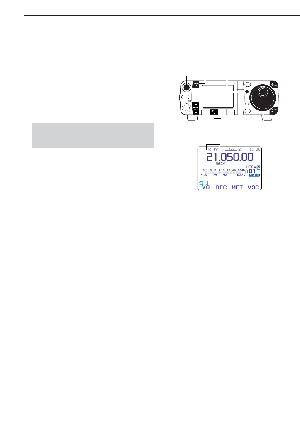
■Operating RTTY (FSK)
When using your RTTY terminal or TNC, consult the
manual that comes with the RTTY terminal or TNC.
qPush [Y(
BAND
)]/[Z(
BAND
)] to select the desired
band or push a band key on the HM-151.
wPush [MODE] momentarily to select RTTY mode.
•After RTTY mode is selected, push [MODE] for 1 sec.
to toggle between RTTY and RTTY-R modes.
eDisplay the RTTY decoder screen.
•Push [F-2 DEC]to display the Baudot decoder screen.
rRotate [DIAL] to simultaneously tune a desired sig-
nal.
•Use [F-2 1/4]in the M
-
3display when critical setting
is required.
•S-meter indicates received signal strength when signal
is received.
•If the received signal cannot be demodulated, try se-
lecting RTTY-R mode (or RTTY mode).
tTransmit a SEND signal from your TNC.
•[TX] indicator lights red.
•The Po meter indicates transmitted RTTY signal
strength.
yOperate the connected PC or TNC (TU) to trans-
mit RTTY (FSK) signals.
“RTTY” or “RTTY-R” appears
[Y]
[Z]
[DIAL]
[MODE][AF] [TX] indicator
[MENU/GRP] [F-2]
•Push and hold [MENU/GRP] for 1 sec. once or twice
to select the menu group S.
•Push [MENU/GRP] momentarily one or more times to
select the menu S
-
1.
51
4RECEIVE AND TRANSMIT
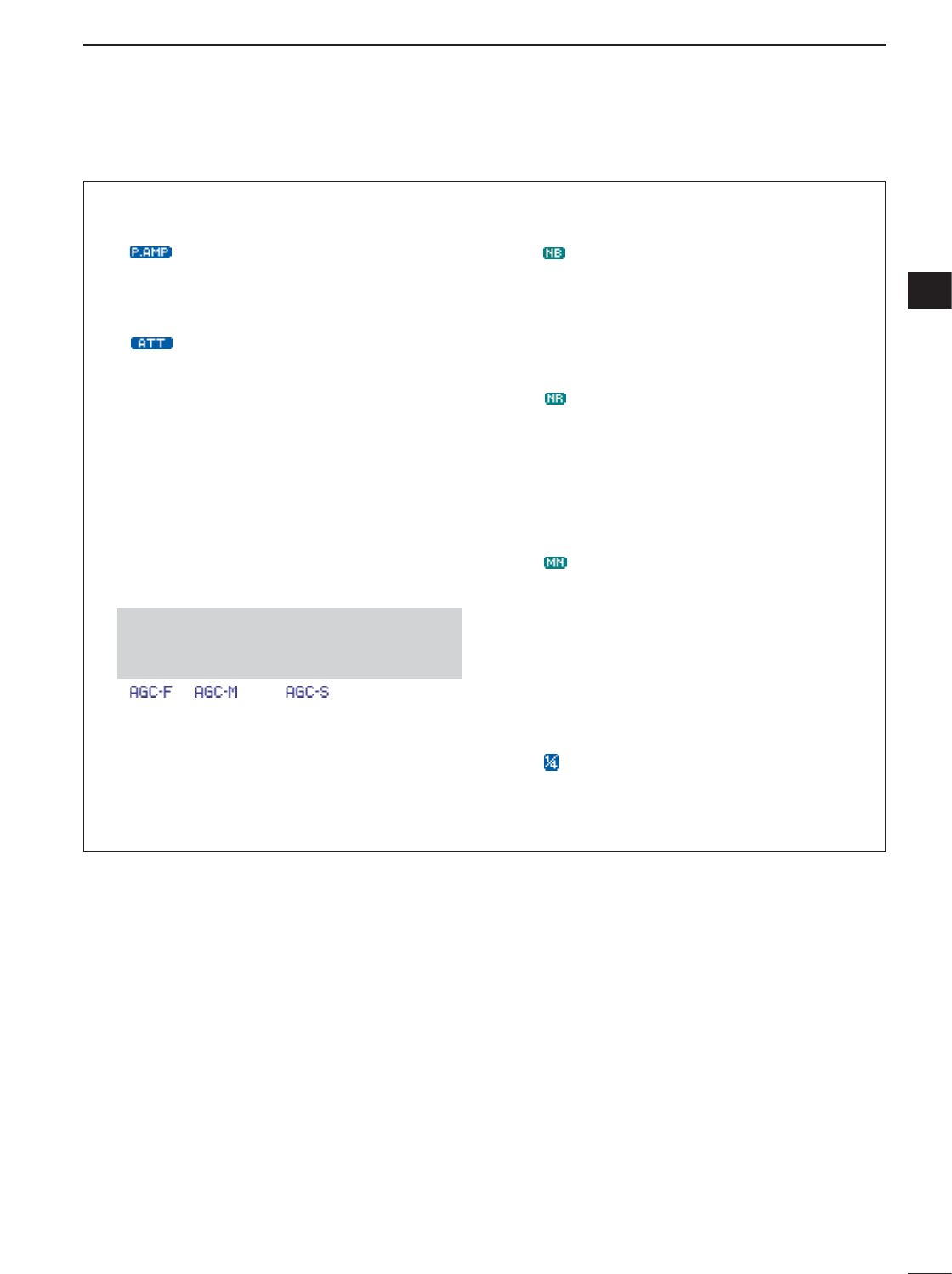
52
4
RECEIVE AND TRANSMIT
4
• Preamp and attenuator (p. 74)
➥Push [P.AMP/ATT] momentarily to turn the pre-
amp ON or OFF.
• “ ” appears when the preamp is set to ON.
➥Push [P.AMP/ATT] for 1 sec. to turn the attenua-
tor ON.
•Push [P.AMP/ATT] momentarily to turn the attenuator
OFF.
• “ ” appears when the attenuator is set to ON.
• Twin PBT (passband tuning) (p. 79)
➥Push [PBT/M-ch/RIT] (switch) momentarily once
or twice to select the twin PBT ON or OFF (M-ch
RIT).
•PBT indicator lights green when the twin PBT is se-
lected.
➥Rotate [PBT/M-ch/RIT] (controls–inner/outer).
•Push [PBT/M-ch/RIT(
CLR
)] to clear the settings.
• AGC (auto gain control) (p. 76)
➥While “M
-
3” is selected, push [F-3 AGC]momen-
tarily one or more times to select AGC fast, AGC
middle and AGC slow.
•“ ,” “ ” and “ ” appears when the
fast time constant, middle time constant and slow
time constant is selected, respectively.
➥While “M
-
3” is selected, push [F-3 AGC]for 1
sec. to enter the AGC set mode.
•Push [F-2 FAST],[F-3 MID]or [F-4 SLOW]to select
the time constant, then rotate [DIAL] to adjust the time
constant.
• Noise blanker (p. 80)
➥Push [NB/ADJ] to turn the noise blanker ON and
OFF.
• “ ” appears when the noise blanker is set to ON.
➥Push [NB/ADJ] for 1 sec. to enter the noise
blanker set mode, then rotate [DIAL] to adjust the
threshold level, or noise pulse width.
• DSP noise reduction (p. 81)
➥Push [NR/LEV] to turn the DSP noise reduction
ON and OFF.
•“ ” appears when the DSP noise reduction is set to
ON.
➥Push [NR/LEV] for 1 sec. to enter the noise re-
duction level set mode, then rotate [DIAL] to ad-
just the DSP noise reduction level.
• Manual notch filter (pgs. 82, 83)
➥Push [MNF/ADJ] to turn the manual notch filter
ON and OFF.
•“ ” appears when the manual notch filter is set to
ON.
➥Push [MNF/ADJ] for 1 sec. to enter the manual
notch filter set mode.
•Push [F-2 NF1],[F-3 NF2]to select the notch filter,
push [F-4 NW]to set the filter width, rotate [DIAL] to
set the attenuating frequency.
•1⁄4function (p. 32)
➥While “M
-
3” is selected, push [F-2 1/4]to turn
the 1⁄4function ON and OFF.
• “ ” indicator appears when the function is activate.
•Push and hold [MENU/GRP] for 1 sec. once or twice
to select the menu group M.
•Push [MENU/GRP] momentarily one or more times
to select the menu M
-
3.
DConvenient functions for receive
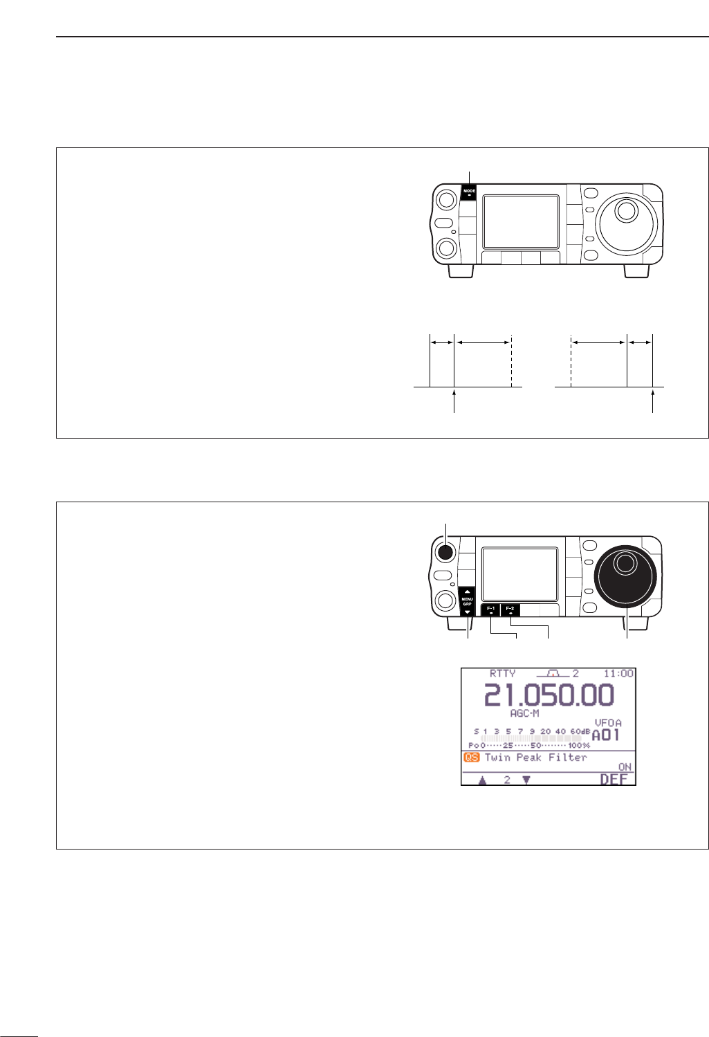
53
4RECEIVE AND TRANSMIT
DRTTY reverse mode
Received characters are occasionally garbled when
the receive signal is reversed between MARK and
SPACE. This reversal can be caused by incorrect
TNC connections, settings, commands, etc.
To receive a reversed RTTY signal correctly, select
RTTY-R (RTTY reverse) mode.
qPush [MODE] several times to select RTTY mode.
w
Push [MODE] for 1 sec. to select RTTY or RTTY-R
mode.
ReverseNormal
BFO
170
Hz
2125
Hz 170
Hz
2125
Hz
BFO
Mark
Space
displayed freq.displayed freq.
Mark
Space
[MODE]
DTwin peak filter
The twin peak filter changes the receive frequency re-
sponse by boosting 2 particular frequencies (2125 and
2295 Hz) for better copying of desired RTTY signals.
qPush [MODE] momentarily to select RTTY mode.
•After RTTY mode is selected, push [MODE] for 1 sec.
to toggle between RTTY and RTTY-R modes.
wPush [AF(
SET
)] momentarily to enter the set mode
menu.
ePush [F-1 QS]to enter the quick set mode.
rPush [F-1 ≤]or [F-2 ≥]to select “Twin Peak
Filter.”
tRotate [DIAL] to select the twin peak filter function
ON or OFF.
•The received audio volume may become greater when
the twin peak filter is turned ON.
yPush [Z(
MENU
/
GRP
)] twice to return the normal op-
erating mode.
[DIAL][MENU/GRP] [F-1] [F-2]
[AF]
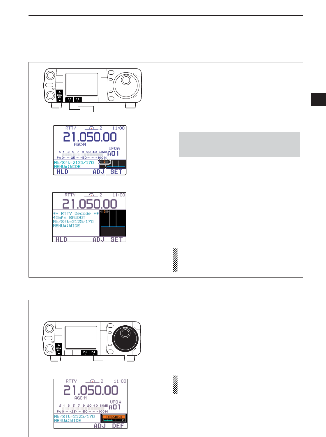
54
4
RECEIVE AND TRANSMIT
4
DFunction for the RTTY decoder indication
The transceiver has an RTTY decoder for Baudot
(mark freq.: 2125 Hz, shift freq.: 170 Hz, 45 bps).
An external terminal unit (TU) or terminal node con-
troller (TNC) is not necessary for receiving a Baudot
signal.
qPush [MODE] momentarily to select RTTY mode.
•After RTTY mode is selected, push [MODE] for 1 sec.
to toggle between RTTY and RTTY-R modes.
wSelect S
-
1.
ePush [F-2 DEC]momentarily to turn the RTTY de-
coder ON.
•When tuned into an RTTY signal, decoded characters
are displayed in the RTTY decoder screen.
rPush [F-1 HLD]momentarily to freeze the current
screen.
•“H” appears while the function is in use.
tPush [Y(
MENU
/
GRP
)] to toggle the normal or wide
screen space.
yPush [F-1 HLD]for 1 sec. to clear the displayed
characters.
uPush [Z(
MENU
/
GRP
)] to exit the RTTY decoder
screen.
The transceiver has an RTTY tuning iindicator to
make correct tuning easier.
The RTTY tuning meter is automatically displayed
when the RTTY decoder is turned ON.
•Push and hold [MENU/GRP] for 1 sec. once or twice
to select the menu group S.
•Push [MENU/GRP] momentarily one or more times to
select the menu S
-
1.
RTTY tuning meter
[MENU/GRP] [F-1] [F-2]
DSetting the decoder threshold level
Adjust the RTTY decoder threshold level if some
characters are displayed when no signal is received.
qCall up the RTTY decoder screen as described
above.
wPush [F-3 ADJ]to select the threshold level set-
ting condition.
eRotate [DIAL] to adjust the RTTY decoder thresh-
old level.
•Push [F-4 DEF]for 1 sec. to select the default condi-
tion.
rPush [Z(
MENU
/
GRP
)] to exit the RTTY decoder
screen.
The UnShift On Space (USOS) function and new
line code can be set in the RTTY decode set mode.
(p. 55)
[DIAL][MENU/GRP] [F-3] [F-4]
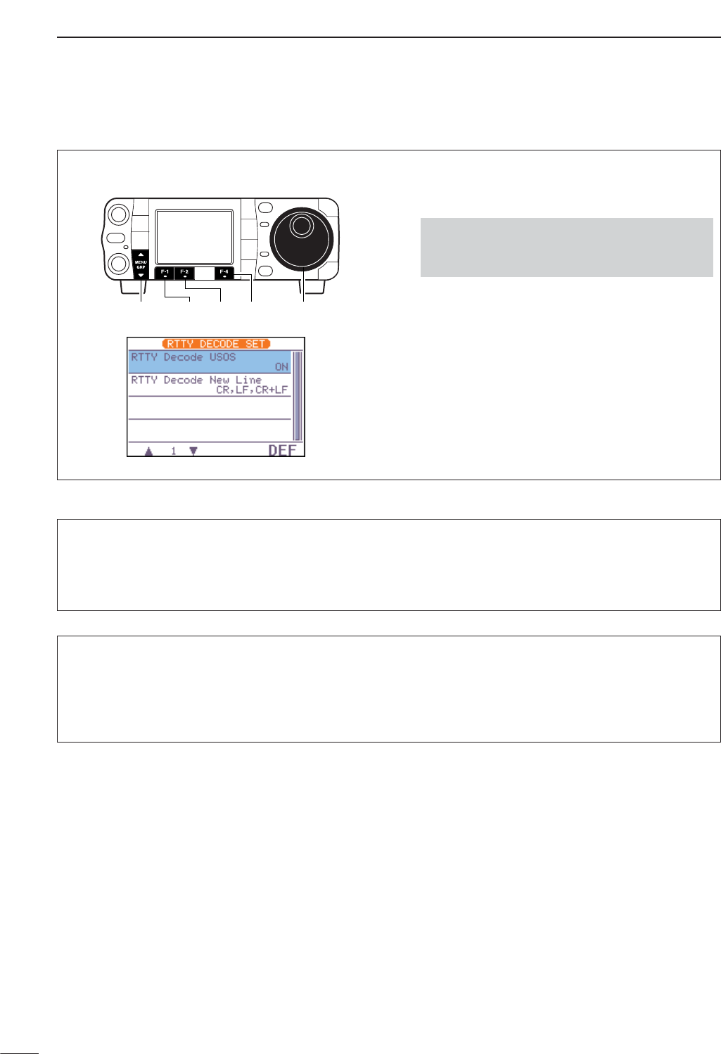
55
4RECEIVE AND TRANSMIT
DRTTY decode set mode
This set mode is used to set the decode USOS func-
tion, etc.
qPush [MODE] momentarily to select RTTY mode.
•After RTTY mode is selected, push [MODE] for 1 sec.
to toggle between RTTY and RTTY-R modes.
wSelect S
-
1.
ePush [F-2 DEC]momentarily to turn the RTTY de-
coder ON.
• RTTY decoder screen appears.
rPush [F-4 SET]to select the RTTY decode set
mode.
tPush [F-1 ≤]or [F-2 ≥]to select the desired set
item.
ySet the desired condition using [DIAL].
•Push [F-4 DEF]for 1 sec. to select a default condition
or value.
uPush [Z(
MENU
/
GRP
)] to exit from set mode.
•Push and hold [MENU/GRP] for 1 sec. once or twice
to select the menu group S.
•Push [MENU/GRP] momentarily one or more times to
select the menu S
-
1.
[MENU/GRP] [F-1] [F-2] [F-4] [DIAL]
1RTTY Decode USOS
This item selects the USOS (UnShift On Space) func-
tion of the internal RTTY decoder.
ON
Decode as letter code
(default)
OFF
Decode as character code
2RTTY Decode New Line Code
This item selects the new line code of the internal
RTTY decoder.
CR : Carriage Return
LF : Line Feed
CR,LF,CR+LF
CR, LF and CR+LF
(default)
CR+LF
CR+LF only
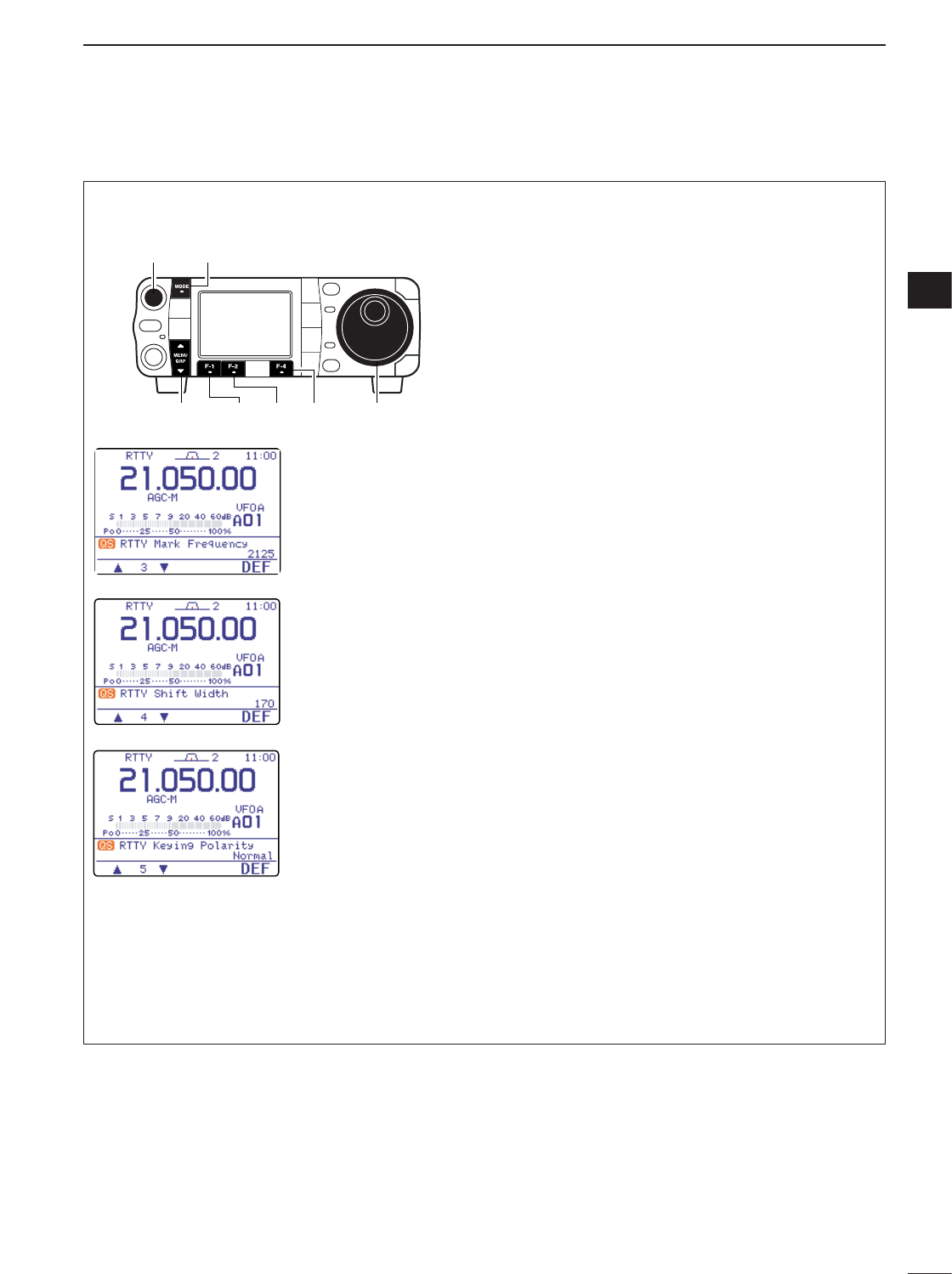
56
4
RECEIVE AND TRANSMIT
4
DPre-setting for using RTTY terminal or TNC
When using your RTTY terminal or TNC, consult the
manual that comes with the RTTY terminal or TNC.
Mark frequency
qPush [MODE] momentarily to select RTTY mode.
•After RTTY mode is selected, push [MODE] for 1 sec.
to toggle between RTTY and RTTY-R modes.
wPush [AF(
SET
)] momentarily to enter the set mode
menu.
ePush [F-1 QS]to enter the quick set mode.
rPush [F-1 Y]or [F-2 Z]to select “RTTY Mark
Frequency.”
tRotate [DIAL] to select the desired frequency.
•Push [F-4 DEF]for 1 sec. to select the default fre-
quency.
Shift width
qEnter the quick set mode as same as above.
wPush [F-1 Y]or [F-2 Z]to select “RTTY Shift
Width.”
eRotate [DIAL] to select the desired shift width.
•Push [F-4 DEF]for 1 sec. to select the default shift
width.
RTTY keying polarity
qEnter the quick set mode as same as above.
wPush [F-1 Y]or [F-2 Z]to select “RTTY key-
ing Polarity.”
eRotate [DIAL] to select the desired keying polarity.
•Push [F-4 DEF]for 1 sec. to select the default polarity.
After Pre-setting is finished, push [Z(
MENU
/
GRP
)] mo-
mentarily twice to return the normal operating mode.
RTTY keying is set to
‘normal’. (default)
normal :
key open=mark
key close=space
reverse:
key open=space
key close=mark
RTTY shift width is
set to 170 Hz.
(default)
170/200/425 Hz are
available.
RTTY mark frequency
is set to 2125 Hz.
(default)
2125, 1615 and 1275
Hz are available.
[MODE][AF]
[MENU/GRP] [F-1] [F-2] [F-4] [DIAL]
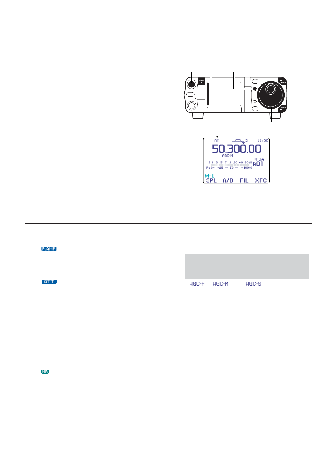
57
4RECEIVE AND TRANSMIT
■Operating AM
qPush [Y(
BAND
)]/[Z(
BAND
)] to select the desired
band or push a band key on the HM-151.
wPush [MODE] momentarily or push and hold for 1
sec. to select AM mode.
•After FM, WFM or AM mode is selected, push [MODE]
for 1 sec. to select from FM, WFM and AM modes.
eRotate [DIAL] to tune in a desired signal.
•The S-meter indicates received signal strength when a
signal is received.
•The default tuning step for AM mode is 1 kHz; this can
be changed using the tuning step program mode. (p. 30)
rRotate [AF] to set audio to a comfortable listening
level.
tPush [PTT] (microphone) to transmit.
•[TX] indicator lights red.
ySpeak into the microphone at your normal voice
level.
•Adjust ‘MIC Gain’ at this step, if necessary. (p. 38)
uRelease [PTT] (microphone) to return to receive.
“AM” appears
[Y]
[Z]
[DIAL]
[MODE][AF] [TX] indicator
DConvenient functions for receive
• Preamp and attenuator (p. 74)
➥Push [P.AMP/ATT] momentarily to turn the pre-
amp ON or OFF.
• “ ” appears when the preamp is set to ON.
➥Push [P.AMP/ATT] for 1 sec. to turn the attenua-
tor ON.
•Push [P.AMP/ATT] momentarily to turn the attenuator
OFF.
• “ ” appears when the attenuator is set to ON.
• Twin PBT (passband tuning) (p. 79)
➥Push [PBT/M-ch/RIT] (switch) momentarily once
or twice to select the twin PBT ON or OFF (M-ch
RIT).
•PBT indicator lights green when the twin PBT is se-
lected.
➥Rotate [PBT/M-ch/RIT] (controls–inner/outer).
•Push [PBT/M-ch/RIT(
CLR
)] to clear the settings.
• Noise blanker (p. 80)
➥Push [NB/ADJ] to turn the noise blanker ON and
OFF.
• “ ” appears when the noise blanker is set to ON.
➥Push [NB/ADJ] for 1 sec. to enter the noise
blanker set mode, then rotate [DIAL] to adjust the
threshold level, or noise pulse width.
• AGC (auto gain control) (p. 76)
➥While “M
-
3” is selected, push [F-3 AGC]momen-
tarily one or more times to select AGC fast, AGC
middle and AGC slow.
•“ ,” “ ” and “ ” appears when the
fast time constant, middle time constant and slow
time constant is selected, respectively.
➥While “M
-
3” is selected, push [F-3 AGC]for 1
sec. to enter the AGC set mode.
•Push [F-2 FAST],[F-3 MID]or [F-4 SLOW]to select
the time constant, then rotate [DIAL] to adjust the time
constant.
•Push and hold [MENU/GRP] for 1 sec. once or twice
to select the menu group M.
•Push [MENU/GRP] momentarily one or more times
to select the menu M
-
3.

58
4
RECEIVE AND TRANSMIT
4
Convenient functions for receive (continued)
• DSP noise reduction (p. 81)
➥Push [NR/LEV] to turn the DSP noise reduction
ON and OFF.
• “ ” appears when the DSP noise reduction is set to
ON.
➥Push [NR/LEV] for 1 sec. to enter the noise re-
duction level set mode, then rotate [DIAL] to ad-
just the DSP noise reduction level.
• Manual notch filter (pgs. 82, 83)
➥Push [MNF/ADJ] to turn the manual notch filter
ON and OFF.
•“ ” appears when the manual notch filter is set to
ON.
➥Push [MNF/ADJ] for 1 sec. to enter the manual
notch filter set mode.
•Push [F-2 NF1],[F-3 NF2]to select the notch filter,
push [F-4 NW]to set the filter width, rotate [DIAL] to
set the notch frequency.
• Auto notch filter (p. 82)
➥Push [ANF/•REC] to turn the auto notch filter ON
and OFF.
• “ ” appears when the auto notch filter is set to ON.
• VSC (voice squelch control) (p. 84)
➥While “S
-
1” is selected, push [F-4 VSC]to turn
the VSC function ON and OFF.
•“”appears when VSC function is set to ON.
DConvenient functions for transmit
• Transmit quality monitor (p. 89)
➥Push [AF(
SET
)], then [F-4 OTH]to enter the mis-
cellaneous (others) set mode. Select an item with
[F-1 ≤]/[F-2 ≥], then rotate [DIAL] to turn the
monitor function ON and OFF.
• VOX (voice operated transmit) (p. 85)
➥While “M
-
3” is selected, push [F-1 VOX]to turn
the VOX function ON and OFF.
• “ ” appears when the VOX function is set to ON.
➥While “M
-
3” is selected, push [F-1 VOX]for 1
sec. to enter the VOX set mode.
•Push [F-1 ≤]/[F-2 ≥]to select an item.
•Rotate [DIAL] to set the value/conditions.
•Push and hold [MENU/GRP] for 1 sec. once or twice
to select the menu group M.
•Push [MENU/GRP] momentarily one or more times
to select the menu M
-
3.
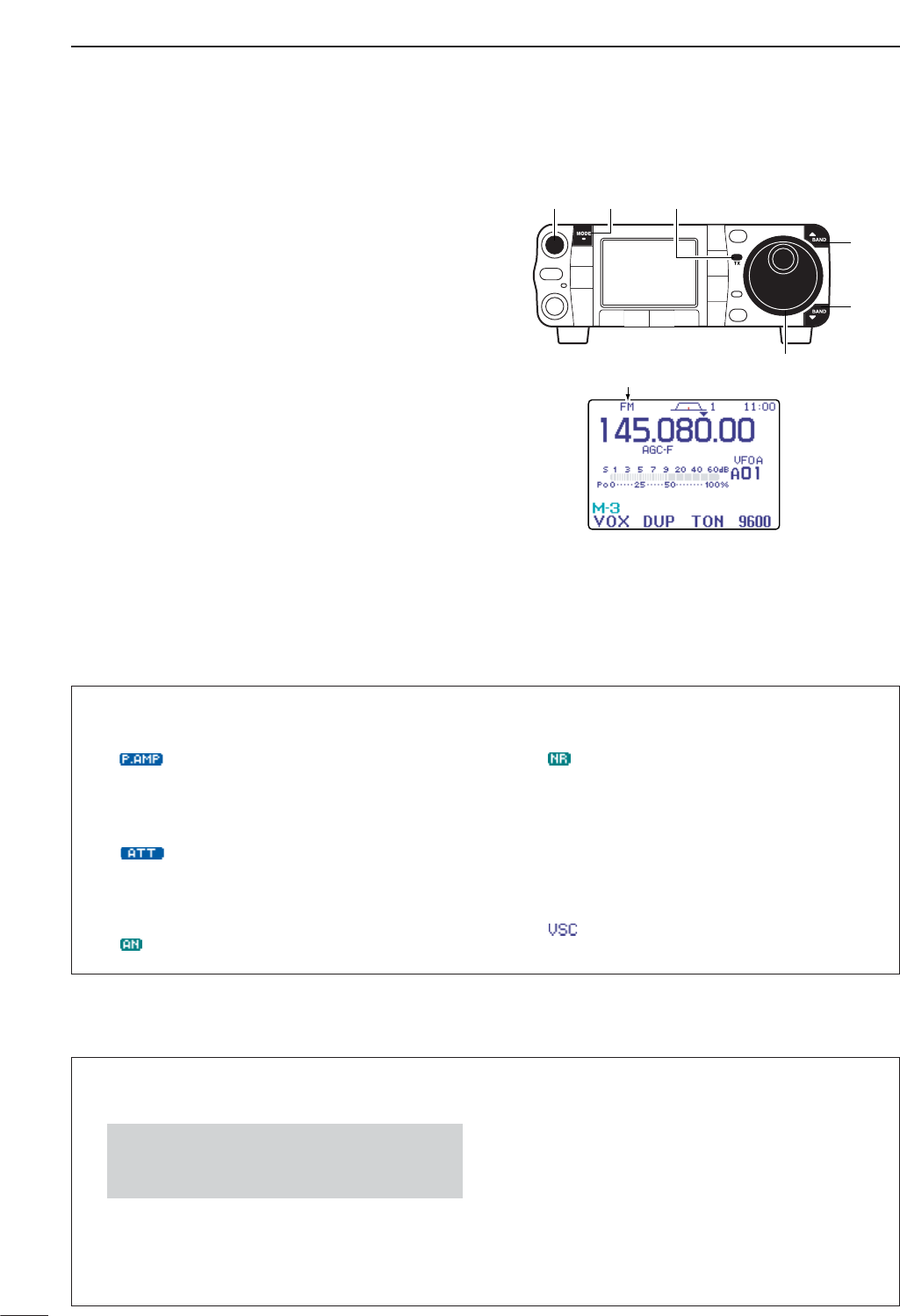
59
4RECEIVE AND TRANSMIT
■Operating FM
qPush [Y(
BAND
)]/[Z(
BAND
)] to select the desired
band or push a band key on the HM-151.
wPush [MODE] momentarily or push and hold for 1
sec. to select FM mode.
•After FM, WFM or AM mode is selected, push [MODE]
for 1 sec. to select from FM, WFM and AM modes.
eRotate [DIAL] to tune in a desired signal.
•The S-meter indicates received signal strength when a
signal is received.
•The default tuning step for FM mode is 1 kHz; this can
be changed using the tuning step program mode. (p. 30)
rRotate [AF] to set audio to a comfortable listening
level.
tPush [PTT] (microphone) to transmit.
•[TX] indicator lights red.
ySpeak into the microphone at your normal voice
level.
•Adjust ‘MIC Gain’ at this step, if necessary. (p. 38)
uRelease [PTT] (microphone) to return to receive.
“FM” appears
[Y]
[Z]
[DIAL]
[MODE][AF] [TX] indicator
DConvenient functions for receive
• Preamp and attenuator (p. 74)
➥Push [P.AMP/ATT] momentarily to turn the pre-
amp ON or OFF.
• “ ” appears when the preamp is set to ON.
➥Push [P.AMP/ATT] for 1 sec. to turn the attenua-
tor ON.
•Push [P.AMP/ATT] momentarily to turn the attenuator
OFF.
• “ ” appears when the attenuator is set to ON.
• Auto notch filter (p. 82)
➥Push [ANF/•REC] to turn the auto notch filter ON
and OFF.
• “ ” appears when the auto notch filter is set to ON.
• DSP noise reduction (p. 81)
➥Push [NR/LEV] to turn the DSP noise reduction
ON and OFF.
• “ ” appears when the DSP noise reduction is set to
ON.
➥Push [NR/LEV] for 1 sec. to enter the noise re-
duction level set mode, then rotate [DIAL] to ad-
just the DSP noise reduction level.
• VSC (voice squelch control) (p. 84)
➥While “S
-
1” is selected, push [F-4 VSC]to turn
the VSC function ON and OFF.
• “ ” appears when VSC function is set to ON.
DConvenient functions for transmit
• VOX (voice operated transmit) (p. 85)
➥While “M
-
3” is selected, push [F-1 VOX]to turn
the VOX function ON and OFF.
• “VOX” appears when the VOX function is set to ON.
➥While “M
-
3” is selected, push [F-1 VOX]for 1
sec. to enter the VOX set mode.
•Push [F-1 ≤]/[F-2 ≥]to select an item.
•Rotate [DIAL] to set the value/conditions.
• Transmit quality monitor (p. 89)
➥Push [AF(
SET
)], then [F-4 OTH]to enter the mis-
cellaneous (others) set mode. Select an item with
[F-1 ≤]/[F-2 ≥], then rotate [DIAL] to turn the
monitor function ON and OFF.
•Push and hold [MENU/GRP] for 1 sec. once or twice
to select the menu group M.
•Push [MENU/GRP] momentarily one or more times
to select the menu M
-
3.
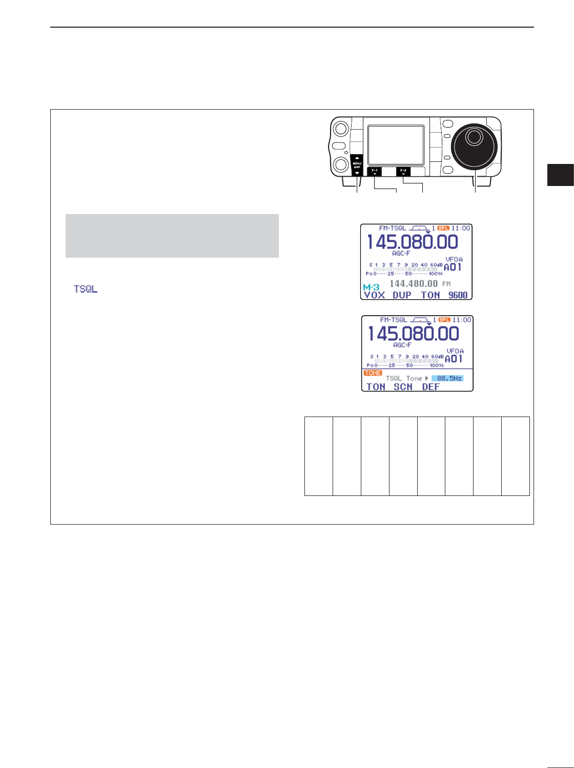
60
4
RECEIVE AND TRANSMIT
4
DTone squelch operation
Tone squelch operation is a method of communica-
tions using selective calling. Only received signals
having a matching tone will open the squelch. Before
communicating using tone squelch, all members of
your party must agree on the tone squelch frequency.
qPush [MODE] one or more times to select FM
mode.
wSelect M
-
3.
ePush [F-3 TON]momentarily several times to turn
the tone squelch function ON.
•“ ” appears.
rPush [F-3 TON]for 1 sec. to enter the FM tone set
mode.
•The selected tone frequency for TSQL appears.
•Other tone function can be set by pushing [F-1 TON].
tRotate [DIAL] to set the desired subaudible tone
frequency.
•See table at right for available tone frequencies.
•Push [F-3 DEF]for 1 sec. to select the default fre-
quency.
•Push [Z(
MENU
/
GRP
)] to exit the FM tone set mode.
yCommunicate in the usual manner.
•Push and hold [PTT] to transmit; release [PTT] to re-
ceive.
• Available tone squelch frequencies (Unit: Hz)
[DIAL][MENU/GRP] [F-3][F-1]
•Push and hold [MENU/GRP] for 1 sec. once or twice
to select the menu group M.
•Push [MENU/GRP] momentarily one or more times to
select the menu M
-
3.
67.0
69.3
71.9
74.4
77.0
79.7
82.5
085.4
088.5
091.5
094.8
097.4
100.0
103.5
107.2
110.9
114.8
118.8
123.0
127.3
131.8
136.5
141.3
146.2
151.4
156.7
159.8
162.2
165.5
167.9
171.3
173.8
177.3
179.9
183.5
186.2
189.9
192.8
196.6
199.5
203.5
206.5
210.7
218.1
225.7
229.1
233.6
241.8
250.3
254.1
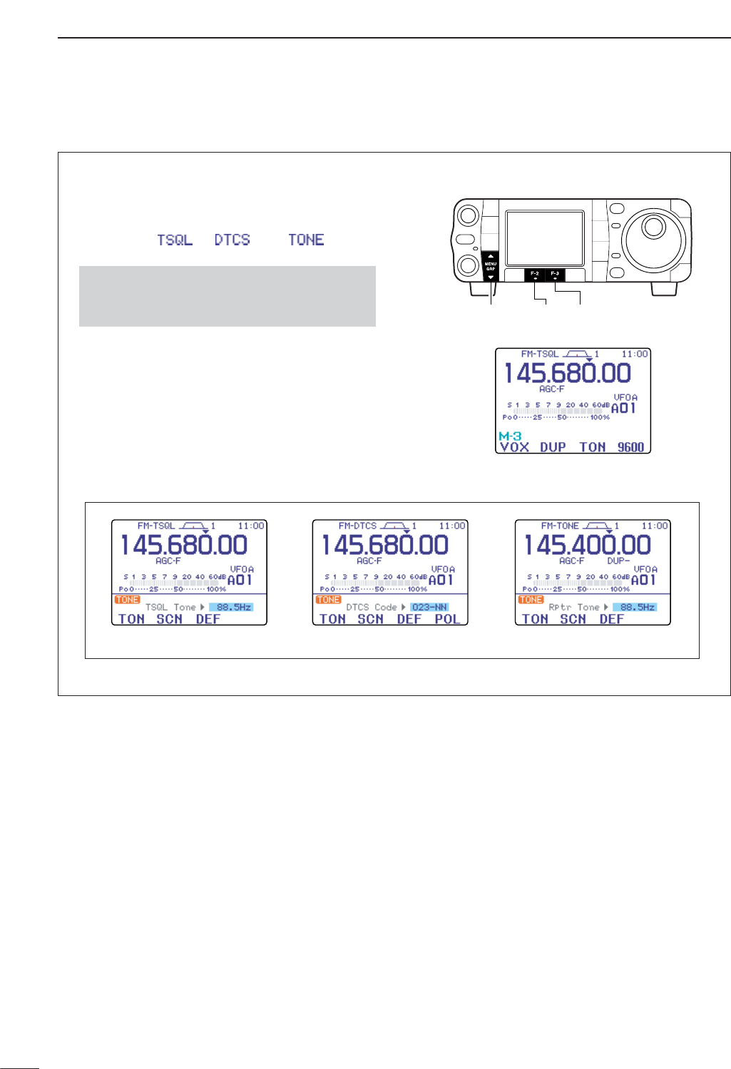
61
4RECEIVE AND TRANSMIT
By monitoring a signal that is being transmitted on a
repeater input frequency, you can determine the tone
frequency necessary to access a repeater.
qDuring tone squelch, DTCS squelch or repeater
operation (“ ,” “ ” or “ ” is dis-
played), select M
-
3.
wPush [F-3 TON]for 1 sec. to enter the FM tone set
mode.
ePush [F-2 SCN]to toggle the tone scan operation
ON and OFF.
•When a matched tone or code is detected, tone scan
automatically stops, the matched tone or code is dis-
played and the tone or code setting is automatically ad-
justed accordingly.
rPush [Z(
MENU
/
GRP
)] to exit the FM tone set mode.
[MENU/GRP] [F-2] [F-3]
•Push and hold [MENU/GRP] for 1 sec. once or twice
to select the menu group M.
•Push [MENU/GRP] momentarily one or more times to
select the menu M
-
3.
DTone scan operation
During tone squelch operation. During DTCS squelch operation. During repeater operation.
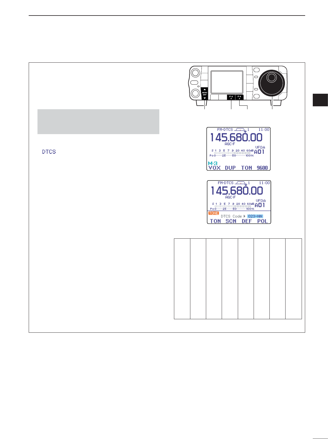
62
4
RECEIVE AND TRANSMIT
4
DDTCS operation
DTCS function is an another method of communica-
tions using selective calling. Only received signals
having a matching 3-digit code will open the squelch.
qPush [MODE] one or more times to select FM
mode.
wSelect M
-
3.
ePush [F-3 TON]once or twice to turn the DTCS
function ON.
•“ ” appears.
rPush [F-3 TON]for 1 sec. to enter the FM tone set
mode.
•The selected DTCS code appears.
•Other tone function can be set pushing [F-1 TON].
tRotate [DIAL] to set the desired DTCS code and
push [F-4 POL]several times to select the desired
code polarity.
NN : Normal polarity is used for both transmit and
receive.
NR : Normal polarity is used for transmit, re-
versed polarity is used for receive.
RN : Reversed polarity is used for transmit, nor-
mal polarity is used for receive.
RR : Reversed polarity is used for both transmit
and receive.
•Push [F-3 DEF]for 1 sec. to select the default code
and polarity.
•Push [Z(
MENU
/
GRP
)] to exit the FM tone set mode.
yCommunicate in the usual manner.
•Push and hold [PTT] to transmit; release [PTT] to re-
ceive.
• Available tone codes
[DIAL][MENU/GRP] [F-3] [F-4]
•Push and hold [MENU/GRP] for 1 sec. once or twice
to select the menu group M.
•Push [MENU/GRP] momentarily one or more times to
select the menu M
-
3.
023
025
026
031
032
036
043
047
051
053
054
065
071
072
073
074
114
115
116
122
125
131
132
134
143
145
152
155
156
162
165
172
174
205
212
223
225
226
243
244
245
246
251
252
255
261
263
265
266
271
274
306
311
315
325
331
332
343
346
351
356
364
365
371
411
412
413
423
431
432
445
446
452
454
455
462
464
465
466
503
506
516
523
526
532
546
565
606
612
624
627
631
632
654
662
664
703
712
723
731
732
734
743
754
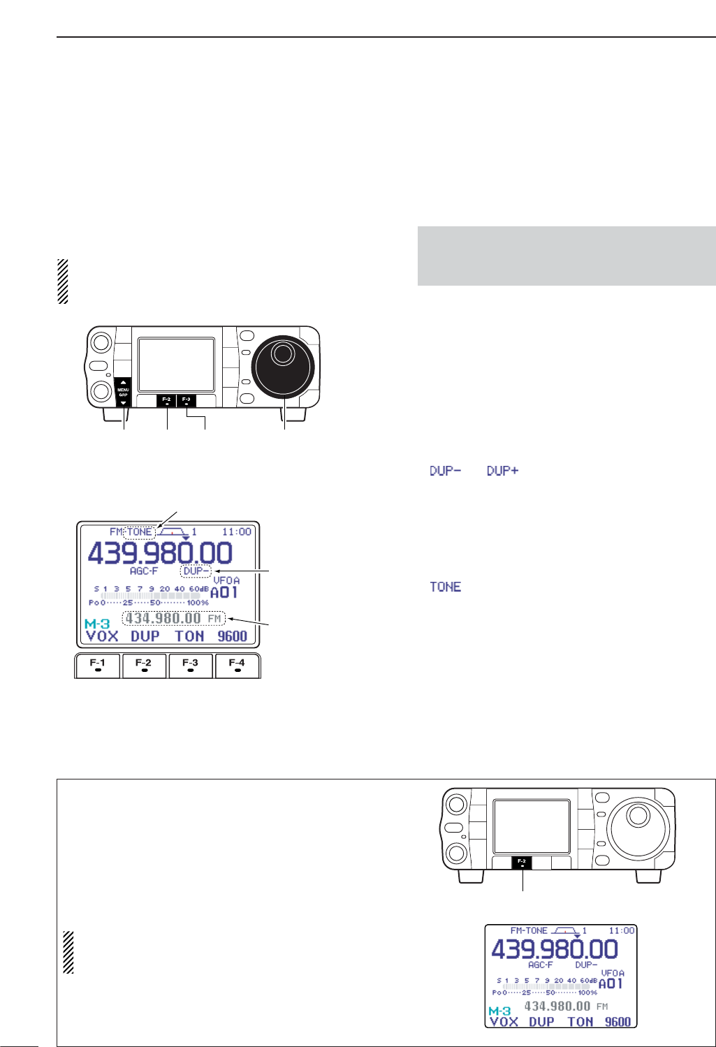
63
4RECEIVE AND TRANSMIT
■Repeater operation
A repeater amplifies received signals and retransmits
them at a different frequency. When using a repeater,
the transmit frequency is shifted from the receive fre-
quency by an offset frequency. A repeater can be ac-
cessed using split frequency operation with the shift
frequency set to the repeater’s offset frequency.
For accessing a repeater which requires a repeater
tone, set the repeater tone frequency in the FM tone
set mode as described on the next page.
• To set the transceiver for repeater operation, follow
the steps qto eto select VFO mode, desired band,
FM mode.
qPush [F-4 V/M]to select VFO mode.
wPush [Y(
BAND
)]/[Z(
BAND
)] to select the desired
band or push a band key on the HM-151.
ePush [MODE] momentarily or push and hold for 1
sec. to select FM mode.
•After FM, WFM or AM mode is selected, push [MODE]
for 1 sec. to select from FM, WFM and AM modes.
rRotate [DIAL] to set the receive frequency (repeater
output frequency).
tSelect M
-
3.
yPush [F-2 DUP]once or twice to set the offset di-
rection.
• “ ” or “ ” appears.
•The default repeater offsets are the standard values of
0.1000 MHz for HF, 0.500 MHz for 50MHz, 0.600 MHz
for 144 MHz, and 5.000 MHz for 430 MHz. The offset
can be adjusted in set mode. (p. 132)
•The transmit frequency can be monitored while pushing
[F-4 XFC]in the M
-
1display.
uPush [F-3 TON]to turn the repeater tone ON.
•“”appears.
•The tone frequency can be set in the FM tone set mode
as described on the next page.
iCommunicate in the usual manner.
•Push and hold [PTT] to transmit; release [PTT] to re-
ceive.
•Push and hold [MENU/GRP] for 1 sec. once or twice to
select the menu group M.
•Push [MENU/GRP] momentarily one or more times to
select the menu M
-
2.
Shifted frequency
and mode appear.
“DUP–” or “DUP+”
appears.
“TONE” appears.
[DIAL][MENU/GRP] [F-2] [F-3]
This function allows you to set repeater operation by
pushing one key.
➥To set the transceiver for repeater operation using
the one-touch repeater function, follow the steps q
to tas above, then push and hold [F-2 DUP]for
1sec.
•Push [F-2 DUP]for 1 sec. again to exit the repeater op-
erating condition.
Set the offset shift direction and frequency in ad-
vance (p. 132) as well as the tone frequency (see
p. 64).
[F-2]
DOne-touch repeater function
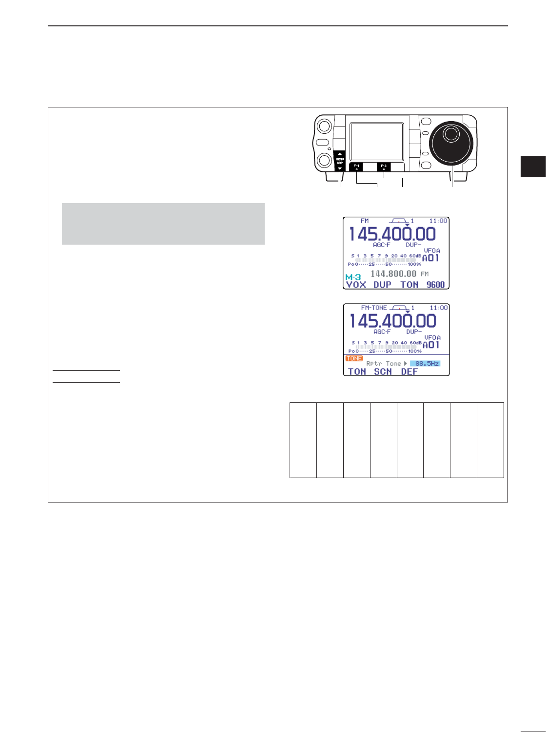
64
4
RECEIVE AND TRANSMIT
4
Some repeaters require subaudible tones to be ac-
cessed. Subaudible tones are superimposed over
your normal signal and must be set in advance. The
transceiver has 50 tones from 67.0 Hz to 254.1 Hz.
Each memory channel can store a different subaudi-
ble tone frequency.
qSelect M
-
3.
wPush [F-3 TON]once or twice to turn the tone en-
coder ON.
•“TONE” appears.
ePush [F-3 TON]for 1 sec. to enter the FM tone set
mode.
•The selected tone frequency appears.
•Other tone function can be set by pushing [F-1 TON].
rRotate [DIAL] to set the desired subaudible tone
frequency.
•See table at right for available tone frequencies.
tPush [Z(
MENU
/
GRP
)] to exit the FM tone set mode.
Store repeater tone frequencies and ON/OFF settings
in memory channels for easy recall. The transceiver’s
repeater tone frequency is set to 88.5 Hz by default.
This can be changed if desired.
• Available tone squelch frequencies (Unit: Hz)
[DIAL][MENU/GRP] [F-3][F-1]
CONVENIENT
•Push and hold [MENU/GRP] for 1 sec. once or twice
to select the menu group M.
•Push [MENU/GRP] momentarily one or more times to
select the menu M
-
3.
DRepeater tone frequency
67.0
69.3
71.9
74.4
77.0
79.7
82.5
085.4
088.5
091.5
094.8
097.4
100.0
103.5
107.2
110.9
114.8
118.8
123.0
127.3
131.8
136.5
141.3
146.2
151.4
156.7
159.8
162.2
165.5
167.9
171.3
173.8
177.3
179.9
183.5
186.2
189.9
192.8
196.6
199.5
203.5
206.5
210.7
218.1
225.7
229.1
233.6
241.8
250.3
254.1
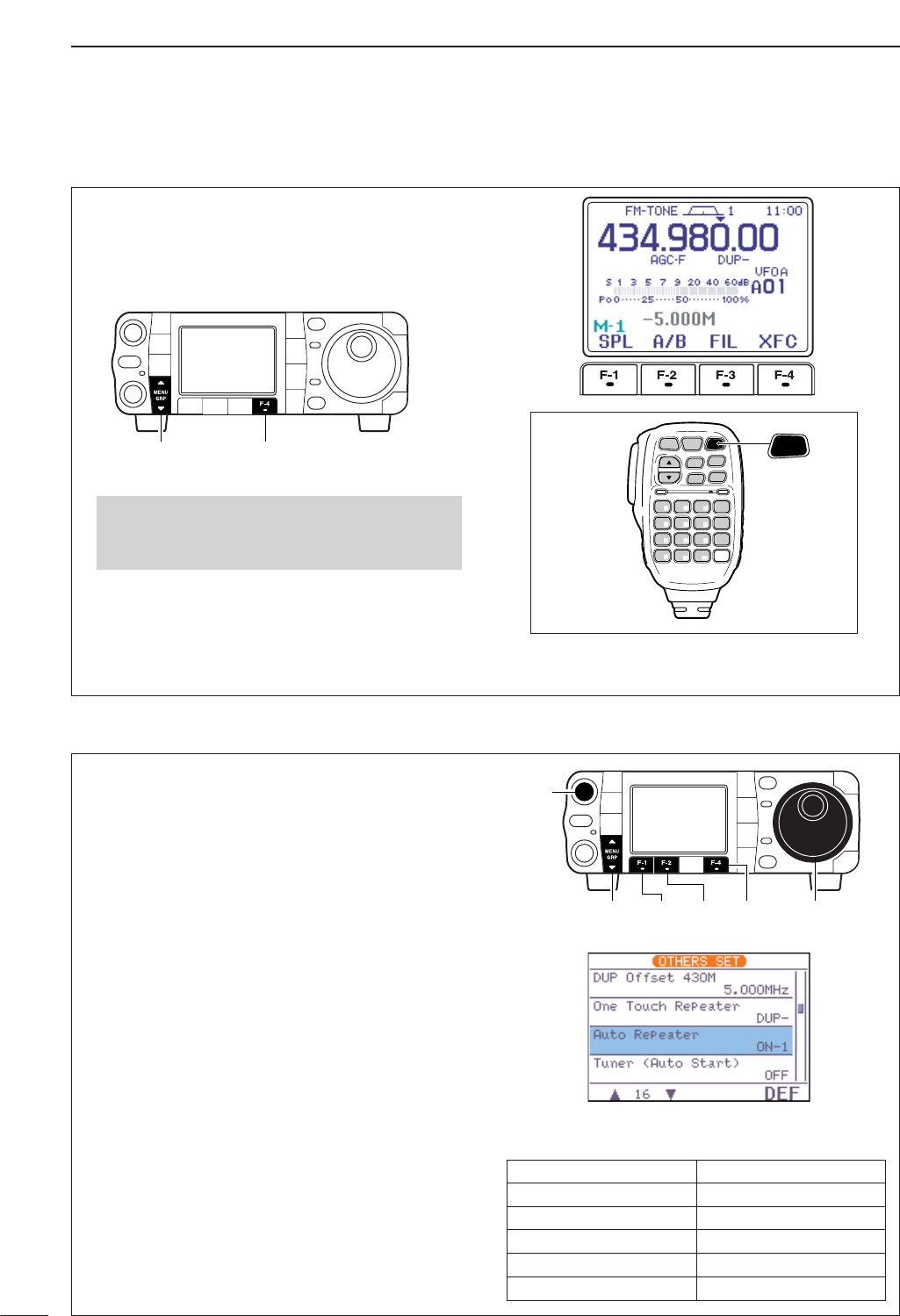
DAuto repeater function
65
4RECEIVE AND TRANSMIT
You may be able to receive the other party’s transmit
signal directly (called ‘listening on the repeater input’)
without having to go through a repeater.
Transmit frequency monitor check (XFC) allows you
to check this.
qSelect M
-
1.
wWhile receiving, push and hold [F-4 XFC]to see if
you can receive the other party’s transmit signal di-
rectly.
•While holding [F-4 XFC], the offset direction and fre-
quency are displayed above the multi-function key in-
dicator.
SPCH
/LOCK
TUNER
/CALL XFC
V/M
F-1 F-2
FIL
MODE
GENE
MW
123
456
789
.0CE
F-INP
ENT
1.8 3.5 7
10 14 18
21 24 28
50 144 430
HM-151
XFC
•Push and hold [MENU/GRP] for 1 sec. once or twice
to select the menu group M.
•Push [MENU/GRP] momentarily one or more times to
select the menu M
-
1.
[MENU/GRP] [F-4]
DTransmit frequency monitor check
This function automatically activates the repeater set-
tings (DUP– or DUP+ and/or tone encoder ON/OFF)
when the operating frequency falls within the general
repeater output frequency range and deactivates
them when outside of the range.
Set the auto repeater function ON-1 (auto duplex set-
ting) or ON-2 (auto duplex setting and activating tone
encoder) in the miscellaneous (others) set mode in
advance (p. 133). When ON-1 or ON-2 are turned on,
repeater settings are automatically activated accord-
ing to the table below right.
ON-1 sets the duplex setting and ON-2 sets the du-
plex setting and tone encoder automatically.
qPush [AF(
SET
)] momentarily to enter the set mode
menu.
wPush [F-4 OTH]to enter the miscellaneous (oth-
ers) set mode.
ePush [F-1 ≤]or [F-2 ≥]to select “Auto Re-
peater.”
rRotate [DIAL] to select the desired auto repeater
condition from ON-1, ON-2 and OFF.
•Push [F-4 DEF]for 1 sec. to return to default setting.
tPush [Z(
MENU
/
GRP
)] twice to return to the normal
operating mode.
• Frequency range and offset direction
[DIAL][MENU/GRP]
[AF]
[F-1] [F-2] [F-4]
FREQUENCY RANGE DUPLEX DIRECTION
145.200–145.495 MHz minus duplex
146.610–146.995 MHz minus duplex
147.000–147.395 MHz plus duplex
442.000–444.995 MHz plus duplex
447.000–449.995 MHz minus duplex
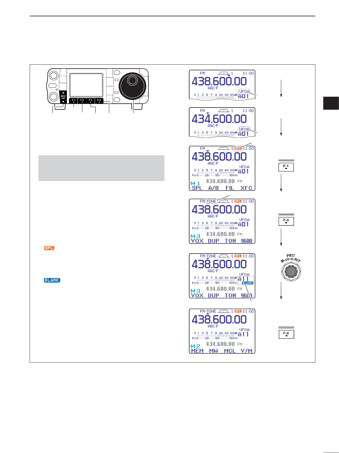
66
4
RECEIVE AND TRANSMIT
4
DStoring a non standard repeater
qTurn the auto repeater function OFF in the miscel-
laneous (others) set mode. (p. 133)
wPush [MODE] to select FM mode.
eSelect M
-
2.
rPush [F-4 V/M]to select VFO mode.
tSelect M
-
1, then push [F-2 A/B]to select VFO A.
yRotate [DIAL] to set the receive frequency (re-
peater output frequency).
uPush [F-2 A/B]to select VFO B.
iRotate [DIAL] to set the transmit frequency (re-
peater input frequency).
oPush [F-2 A/B]to select VFO A.
!0 Push [F-1 SPL]to turn the split function ON.
• “ ” appears.
!1 Select M
-
3, then push [F-3 TON]to turn on the
previously set tone encoder ON. (p. 64)
!2 Rotate [M-ch] to select the desired memory chan-
nel.
• “ ” appears when the blank channel is selected.
!3 Select M
-
2, then push [F-2 MW]for 1 sec. to store
the contents in the selected memory channel.
Rotate
Push
push
TON
SPL
push
MW
Set the frequency.
Selected M2, then
Selected M3, then
Set the frequency.
Appears
Appears
Select
Select
Select
•Push and hold [MENU/GRP] for 1 sec. once or twice
to select the menu group M.
•Push [MENU/GRP] momentarily one or more times to
select the menu M
-
2.
[DIAL][MENU/GRP]
[F-1]
[F-2] [F-3] [F-4]
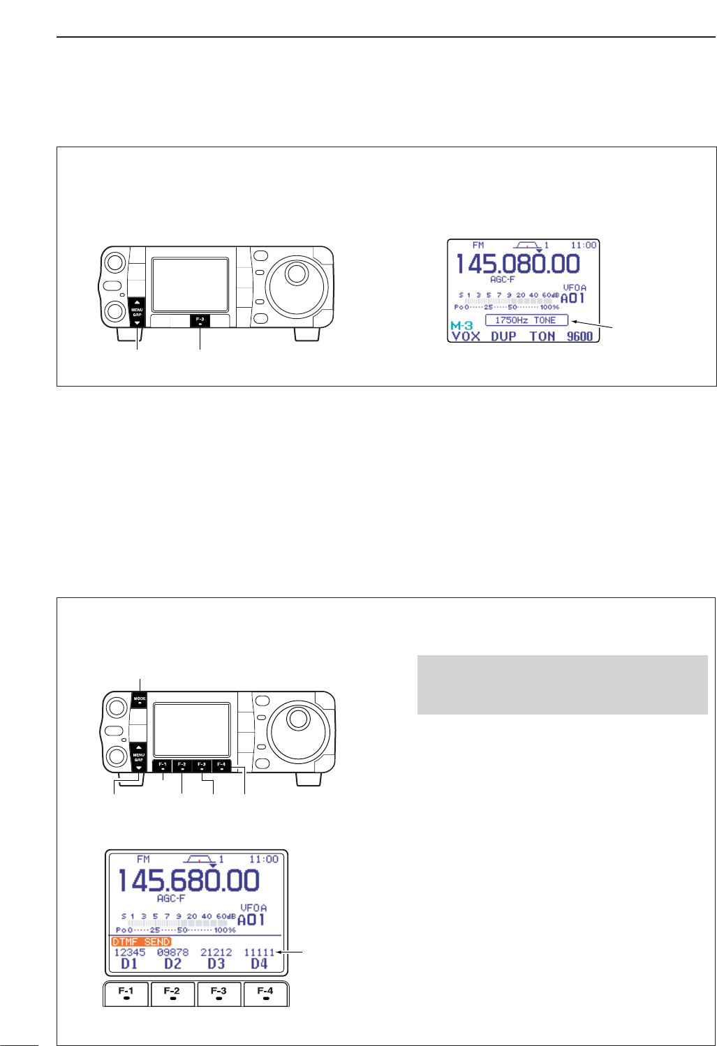
67
4RECEIVE AND TRANSMIT
A 1750 Hz tone is required to access most European
repeaters.
➥While pushing [PTT], push [F-3 TON]in the M-3
menu during repeater operation. (pgs. 63, 66)
Popup indication
appears.
[MENU/GRP] [F-3]
■1750 Hz tone burst
To transmit a DTMF code using a DTMF send menu,
program the desired code in advance as described on
next page.
• Transmitting
qSelect FM mode with [MODE].
wSelect S
-
1.
ePush [F-2 DTM]to enter the DTMF send menu.
•If the DTMF root menu appears, push [F-1 SND]. The
DTMF starting menu can be changed in the miscella-
neous (others) set mode (see p.136).
rPush [F-1 D1]—[F-4 D4]to transmit the DTMF
code.
•“D1”– “D4” are highlighted while transmitting.
•Set the DTMF speed from 100–500 msec. (100 msec.
steps). See next page for DTMF set mode.
tPush [Z(
MENU
/
GRP
)] twice to exit DTMF send
menu and return to the normal FM mode display.
•Push and hold [MENU/GRP] for 1 sec. once or twice
to select the menu group S.
•Push [MENU/GRP] momentarily one or more times to
select the menu S
-
1.
• DTMF send menu
DTMF code
sequence
[MODE]
[MENU/GRP]
[F-1]
[F-2] [F-3] [F-4]
DDTMF send menu
■DTMF memory encoder
DTMF tones are used for autopatching, controlling
other equipment, etc. The transceiver has 4 DTMF
memory channels (D1–D4) for storage of often-used
DTMF codes sequence of up to 24 digits.
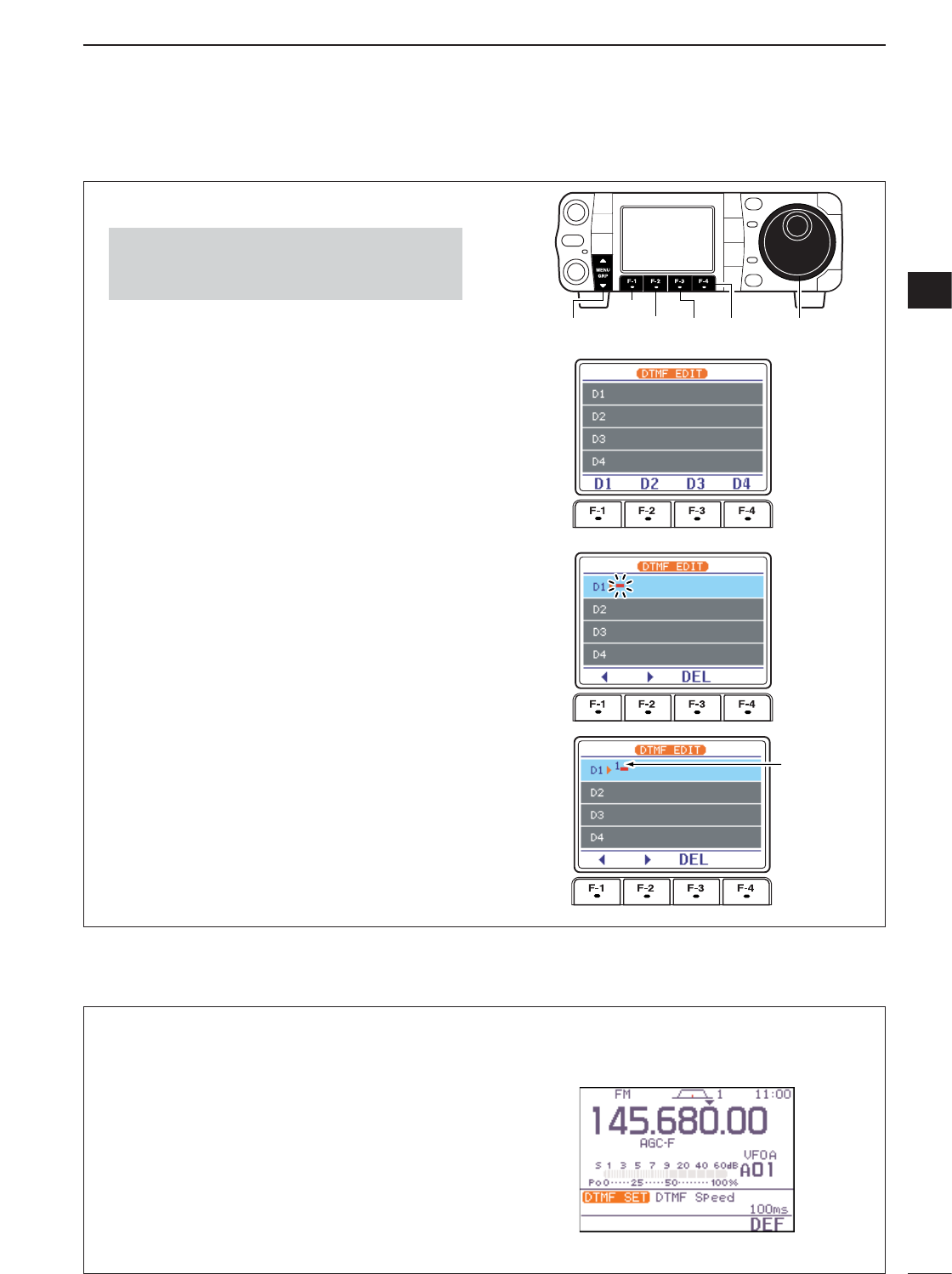
68
4
RECEIVE AND TRANSMIT
4
DProgramming a DTMF code
qPush [MODE] to select FM mode.
wSelect S
-
1.
ePush [F-2 DTM]then [Z(
MENU
/
GRP
)] to select the
DTMF root menu.
•If the DTMF root menu appears, skip pushing
[Z(
MENU
/
GRP
)]. The DTMF starting menu can be
changed in the miscellaneous (others) set mode. (see
p.136)
rPush [F-2 EDT]to enter the DTMF edit menu.
tPush [F-1 D1]—[F-4 D4]to select the desired
DTMF memory channel.
ySelect the desired code by rotating [DIAL].
•Push [F-1 Å]or [F-2 Ç]for cursor movement.
•Push [F-3 DEL]to delete the selected code.
uRepeat steps tand yuntil the desired contents
are input.
iPush [Z(
MENU
/
GRP
)] to return to memory channel
selection mode, then select the next memory chan-
nel and repeat steps tand ufor code input, if de-
sired.
oPush [Z(
MENU
/
GRP
)] twice to exit the keyer edit
mode.
DTMF memory channel select
Selected
code
[MENU/GRP]
[F-1]
[F-2] [F-3] [F-4] [DIAL]
•Push and hold [MENU/GRP] for 1 sec. once or twice
to select the menu group S.
•Push [MENU/GRP] momentarily one or more times to
select the menu S
-
1.
The rate at which DTMF memories send individual
DTMF characters can be set to accommodate oper-
ating needs.
qSelect the DTMF root menu as described above.
wPush [F-4 SET]to enter the DTMF set mode.
eRotate [DIAL] to set the desired DTMF speed.
•Four rates are available: “100 ms” is the fastest; “500
ms” is slowest.
•Push [F-4 DEF]for 1 sec. to select the default rate.
rPush [Z(
MENU
/
GRP
)] twice to exit the DTMF set
mode and return to the normal FM mode display.
DDTMF speed
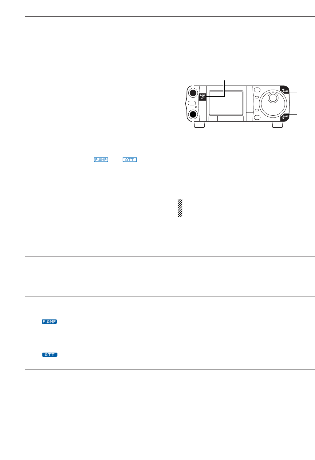
69
4RECEIVE AND TRANSMIT
■TV channel operation
qPush and hold [AF(
SET
)] for 1 sec. to turn the TV
mode ON.
•Push and hold [AF(
SET
)] for 1 sec again to exit the TV
mode.
wRotate [M-ch] (inner) control to select the desired
TV channel.
•[Y(
BAND
)]/[Z(
BAND
)] keys also select the TV channel.
•The popup indicator appears and shows the selected
channel number. (The popup indicator can be turned
OFF in the display set mode. p.128)
ePush [P.AMP/ATT] momentarily to turn the preamp
ON and OFF; push and hold for 1 sec. to turn the
12 dB attenuator ON.
•The popup indicator, “ ” or “ ,” appears
when the preamp is ON or attenuator is ON, respec-
tively. (The popup inidicator can be turned OFF in the
display set mode. p. 128)
•Each channel can store the preamp or attenuator
ON/OFF conditions independently.
•Only one of these functions can be activated at a time.
rRotate [AF] to set a suitable audio level. WARNING! NEVER watch a TV program while
driving a vehicle. Safe driving requires your full at-
tention–anything less may result in an accident.
[Y]
[Z]
[P.AMP/ATT][AF]
[M-ch]
DConvenient functions for receive
• Preamp and attenuator (p. 74)
➥Push [P.AMP/ATT] momentarily to turn the pre-
amp ON or OFF.
• “ ” appears when the preamp is set to ON.
➥Push [P.AMP/ATT] for 1 sec. to set the attenua-
tor ON.
•Push [P.AMP/ATT] momentarily to turn the attenuator
OFF.
• “ ” appears when the attenuator is set to ON.
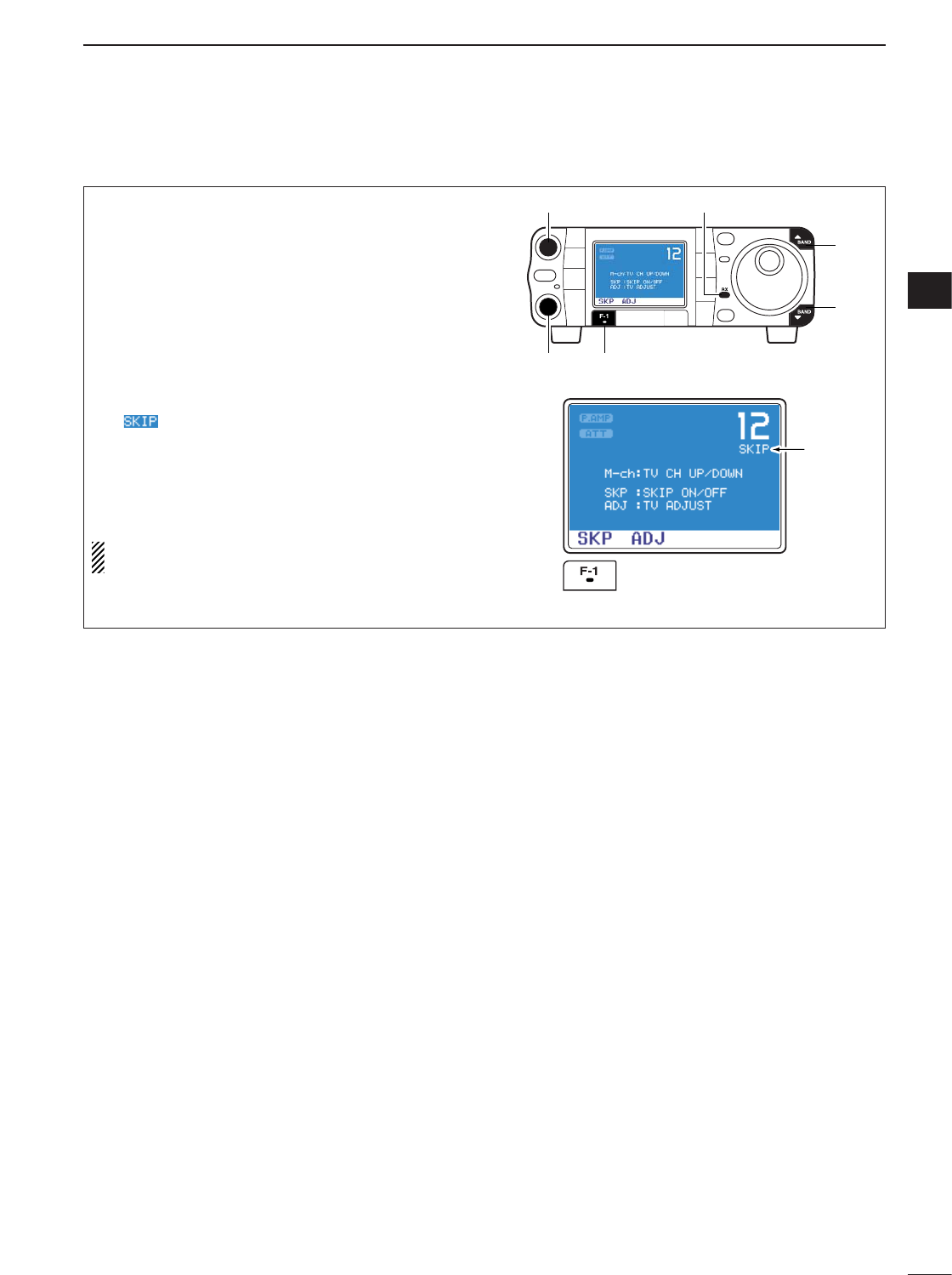
70
4
RECEIVE AND TRANSMIT
4
Unwanted channels can be skipped for rapid selec-
tion, etc.
qSelect the TV mode.
•Push and hold [AF(
SET
)] for 1 sec.
wPush [AF(
SET
)] momentarily to turn the blue-back-
ground display ON.
eRotate [M-ch] (inner) control to select the desired
TV channel to be a skipped.
•[Y(
BAND
)]/[Z(
BAND
)] keys also select the TV channel.
rPush [F-1 SKP]to turn the channel skip setting
ON.
•“ ” appears and [RX] indicator turns OFF.
•Push [F-1 SKP]again to cancel the skip setting.
tRepeat steps e,rto set the other channels, if de-
sired.
yPush [AF(
SET
)] momentarily to turn the blue-back-
ground display OFF.
All channels (including skip channels) can be se-
lected on the blue-background display.
Push [F-1 SKP]
Appears
[Y]
[Z]
[AF] [RX] indicator
[F-1][M-ch]
DSkip channel setting
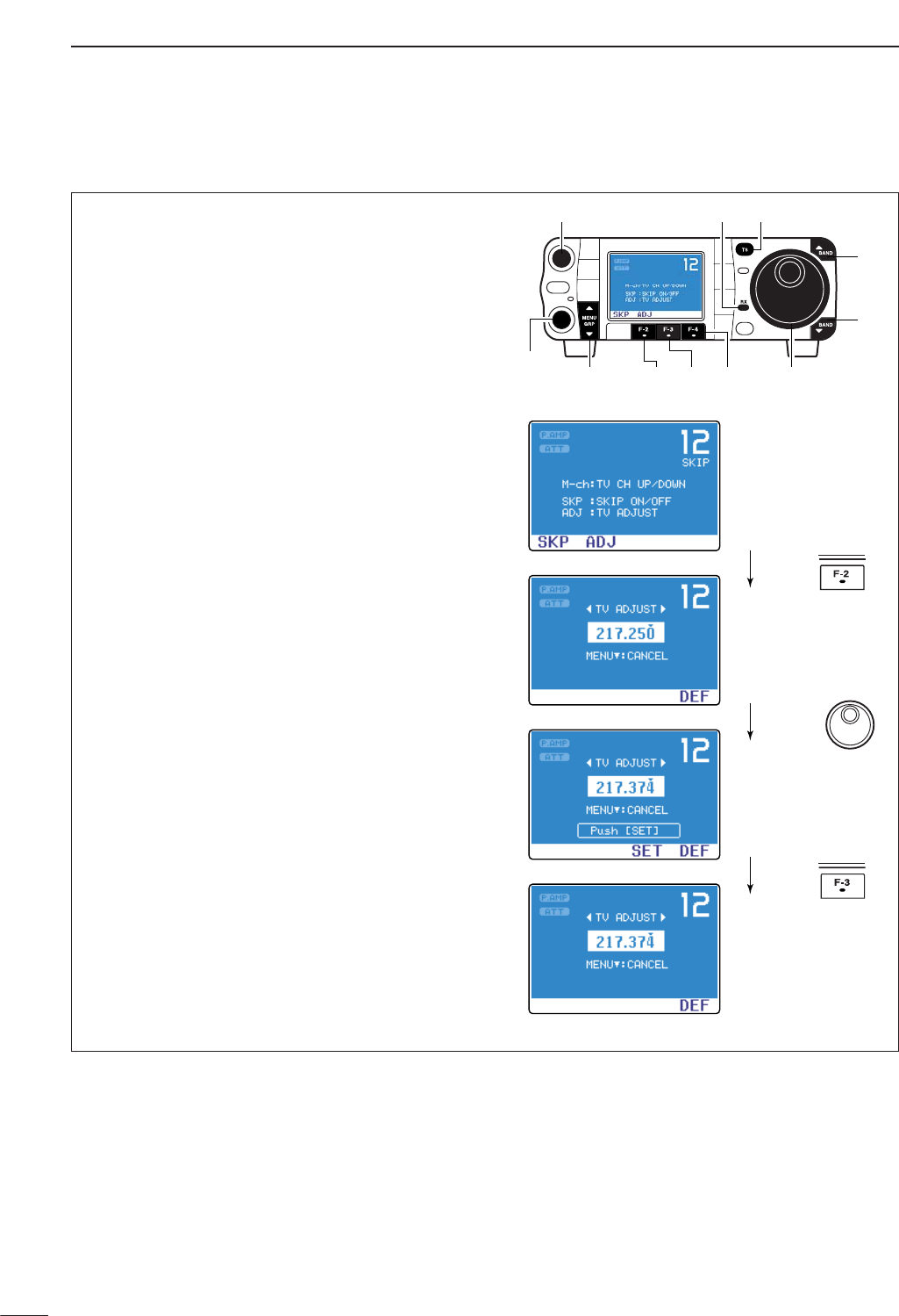
71
4RECEIVE AND TRANSMIT
qSelect the TV mode.
•Push and hold [AF(
SET
)] for 1 sec.
wPush [AF(
SET
)] momentarily to turn the blue-back-
ground display ON.
eRotate [M-ch] (inner) control to select the desired
TV channel.
•[Y(
BAND
)]/[Z(
BAND
)] keys also select the TV channel.
rPush [F-2 ADJ]to enter the channel frequency set
mode.
•The selected channel frequency appears and [RX] in-
dicator blinks.
•Push [TS] to toggle the tuning step from 1 kHz and 250
kHz.
•Push [Z(
MENU
/
GRP
)] to exit the channel frequency set
mode.
tRotate [DIAL] to adjust the channel frequency.
•“Push [SET]” blinks.
•Push [Z(
MENU
/
GRP
)] to cancel the setting.
yPush [F-3 SET]to set the channel frequency.
•Push [F-4 DEF]for 1 sec. to return to the default fre-
quency.
uPush [Z(
MENU
/
GRP
)] to exit the channel frequency
set mode.
•The channel frequency disappears and [RX] indicator
stops blinking.
iRepeat steps eto uto set the another channels,
if desired.
oPush [AF(
SET
)] momentarily to turn the blue-back-
ground display OFF.
Push
Rotate
ADJ
Push
SET
[Y]
[Z]
[DIAL]
[AF] [TS][RX] indicator
[MENU/GRP] [F-4][F-2]
[M-ch]
[F-3]
DChannel frequency adjustment
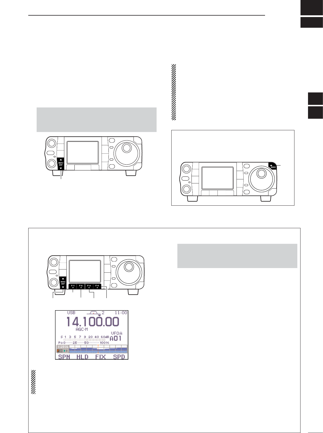
5
72
FUNCTIONS FOR RECEIVE
■Simple band scope
This DSP-based simple band scope allows you to dis-
play conditions on the selected band, as well as rela-
tive strength of signals. The IC-7000 has two modes
for the spectrum indication—one is fix mode, and an-
other one is center mode.
➥Select G
-
1(Scope).
NOTE: The IC-7000’s simple band scope can mon-
itor the displayed frequency during sweeping. Both
of the receving and sweeping functions use the
same receive circuit which switch alternatively es-
pecially at high speed. Thus this switching sound
during may be irritating to listen to. If so, set the de-
sired monitoring sound, “FAST Sweep Sound,”
or change the fast sweep setting, “FAST
Sweep,” in the scope set mode (p. 73).
[MENU/GRP]
•Push and hold [MENU/GRP] for 1 sec. once or twice
to select the menu group G(Graphic).
•Push [MENU/GRP] momentarily one or more times to
select the menu G
-
1(Scope).
DFix mode
Displays signals within the specified frequency range.
The selected band conditions can be observed at a
glance when using this mode.
NOTE: If there is a lot of signal noise, turn the pre-
amp OFF and the attenuator ON (p. 74) to reduce
the input level and improve the readability of the
scope.
qSet a mode and frequency.
wSelect G
-
1(Scope).
ePush [F-3 FIX]momentarily to select the fix
mode.
• “O” and readout frequency indicator appear when the
fix mode is selected.
rPush [F-4 SPD]momentarily to select the sweep
speed.
• “≈” or “≈≈” appears when Slow speed or Fast speed is
selected, respectively.
tPush [F-1 SPN]one or more times to select the
desired steps.
•±10, 25, 50, 100 and 250 kHz are available.
•Push and hold [F-1 SPN]for 1 sec. to select the ±10
kHz step.
• “<” or “>” indicates when the displayed frequency is out
of range. The scope center position can be set to the
displayed frequency by pushing and holding [F-3
FIX]for 1 sec.
•The simple band scope operates in the peak level hold
mode. Peak levels are displayed in the background of
the current spectrum in a different color until the receive
frequency changes. This can be cleared by pushing
and holding [F-2 HLD]for 1 sec., or deactivated in the
scope set mode. (p. 73)
yPush [F-2 HLD]to freeze the current spectrum dis-
play.
•“H” appears while the function is in use.
•Push and hold [MENU/GRP] for 1 sec. once or twice
to select the menu group G(Graphic).
•Push [MENU/GRP] momentarily one or more times to
select the menu G
-
1(Scope).
[MENU/GRP]
[F-1]
[F-2] [F-3] [F-4]
Quick entry
➥Push [Y(
BAND
)] for 1 sec. to turn the simple
band scope ON and OFF.
•Push [Z(
MENU
/
GRP
)] also to turn OFF.
[Y]
4
5
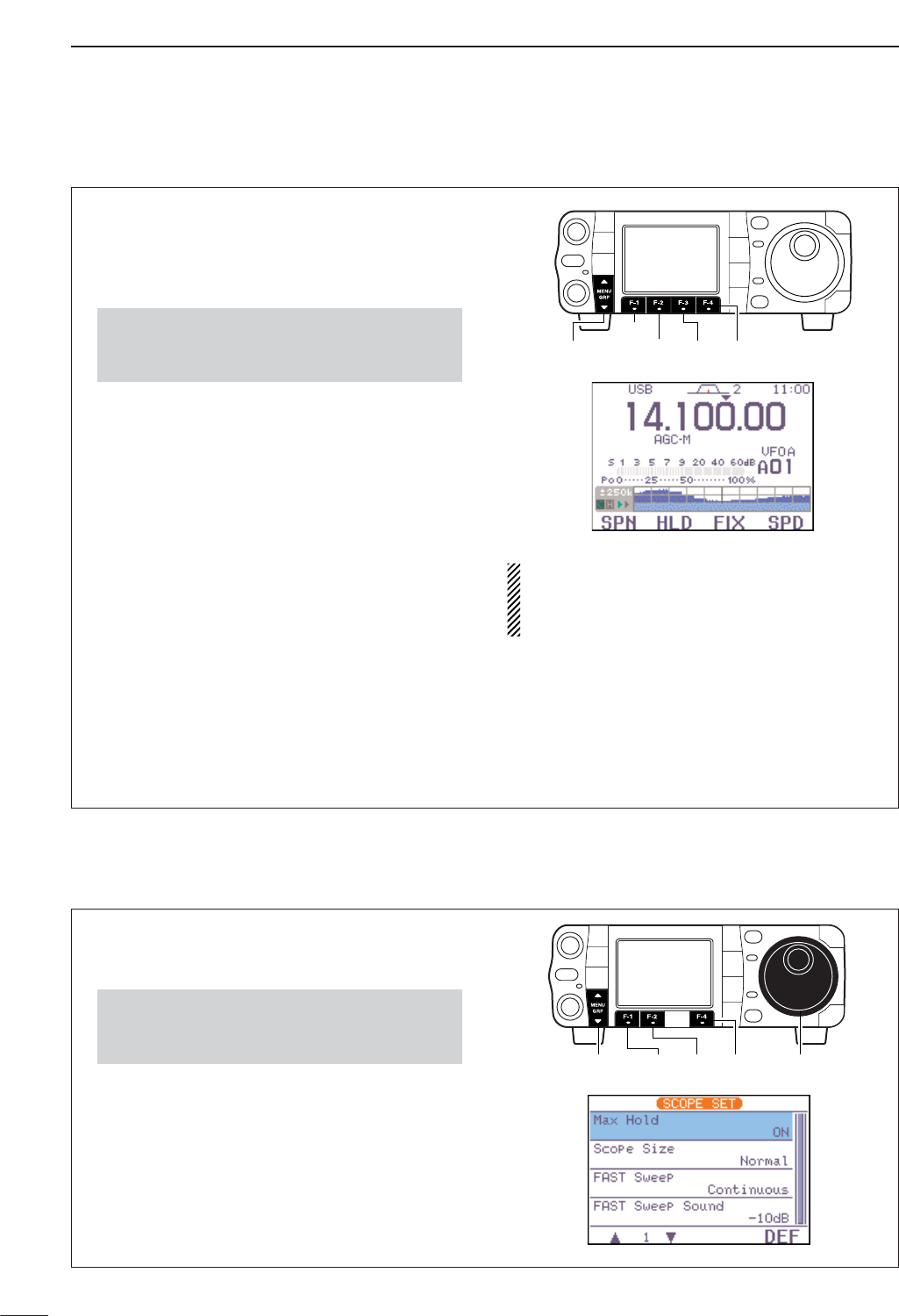
73
5FUNCTIONS FOR RECEIVE
DCenter mode
Displays signals around the displayed frequency
within the selected span. The set frequency is always
displayed at the center of the screen.
qSet a mode and frequency.
wSelect G
-
1(Scope).
ePush [F-3 FIX]momentarily to select the center
mode.
•“=” appears when the center mode is selected.
rPush [F-4 SPD]momentarily to select the sweep
speed.
• “≈” or “≈≈” appears when Slow speed or Fast speed is
selected, respectively.
tPush [F-1 SPN]one or more times to select the
desired steps.
•±10, 25, 50, 100 and 250 kHz are available.
•Push and hold [F-1 SPN]for 1 sec. to select the ±10
kHz step.
•The simple band scope operates in the peak level hold
mode. Peak levels are displayed in the background of
the current spectrum in a different color until the receive
frequency changes. This can be cleared by pushing
and holding [F-2 HLD]for 1 sec., or deactivated in the
scope set mode. (below)
yPush [F-2 HLD]to freeze the current spectrum dis-
play and range.
•“H” and readout frequency indicator appear while the
function is in use.
NOTE: If there is a lot of signal noise, turn the pre-
amp OFF and the attenuator ON (p. 74) to reduce
the input level and improve the readability of the
scope.
[MENU/GRP]
[F-1]
[F-2] [F-3] [F-4]
•Push and hold [MENU/GRP] for 1 sec. once or twice
to select the menu group G(Graphic).
•Push [MENU/GRP] momentarily one or more times to
select the menu G
-
1(Scope).
DScope set mode
This set mode is used to set the peak hold function
and scope size setting.
qSelect G
-
1(Scope).
wPush and hold [F-4 SPD]for 1 sec. to enter the
scope set mode.
ePush [F-1 ≤]or [F-2 ≥]to select the desired set
item.
rSet the desired condition using [DIAL].
•Push [F-4 DEF]for 1 sec. to select a default condition.
tPush [Z(
MENU
/
GRP
)] to exit from set mode.
[MENU/GRP] [F-1] [F-2] [F-4] [DIAL]
•Push and hold [MENU/GRP] for 1 sec. once or twice
to select the menu group G(Graphic).
•Push [MENU/GRP] momentarily one or more times to
select the menu G
-
1(Scope).
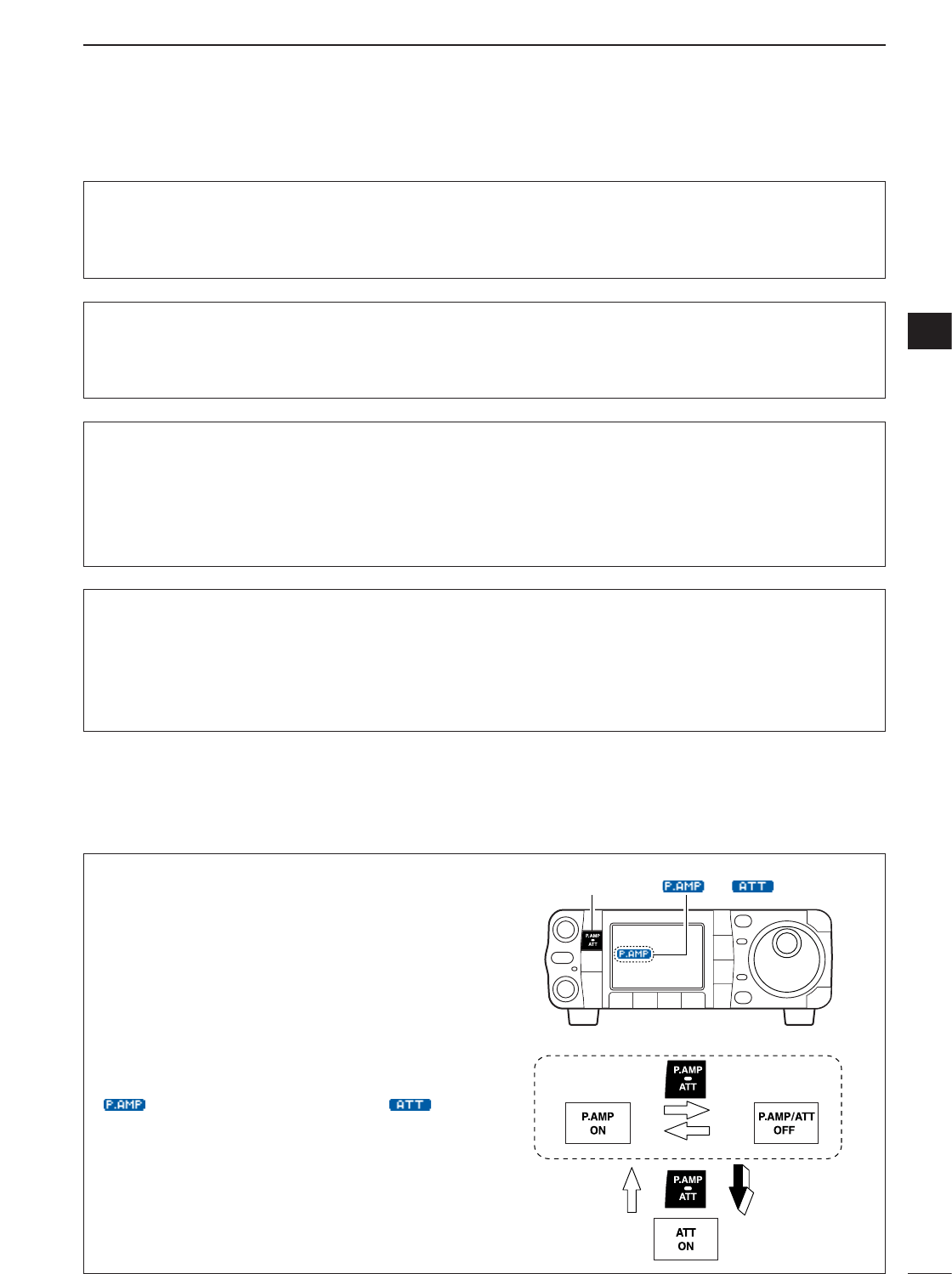
74
5
FUNCTIONS FOR RECEIVE
5
■Preamp and attenuator
The preamp amplifies received signals in the receiver
input (front end) circuit to improve the S/N ratio and
sensitivity. Turn this function ON when receiving weak
signals.
The attenuator prevents a strong undesired signal
near the desired frequency or near your location,
such as from a broadcast station, from causing dis-
tortion or spurious signals.
Push [P.AMP/ATT] momentarily to turn the preamp
ON and OFF; push and hold for 1 sec. to turn the at-
tenuator ON.
•“ ” appears when the preamp is ON; “ ” ap-
pears when the 12 dB attenuator is ON.
• Only one of these functions can be activated at a time.
momentarily
momentarily 1 sec.
[P.AMP/ATT] “ ” or “ ” appears.
Scope set mode (Continued)
1Max Hold
This item turns the peak level holding function ON
and OFF.
ON
Peak hold is turned ON.
(default)
OFF
Peak hold is turned OFF.
2Scope Size
This item turns the scope size setting normal and
wide.
Normal
Normal size is selected.
(default)
Wide
Wide size is selected.
3FAST Sweep
This item selects the sweep speed setting. Continuous
Push [F-4 SPD]momentar-
ily to toggle the sweep
speed Fast and Slow contin-
uously. (default)
1 Sweep
Sweep speed changes Slow
to Fast just for one sweep
every pushing [F-4 SPD]
momentarily.
4FAST Sweep Sound
This item sets the monitoring sound level for fast
sweeping.
-10dB :Monitoring sound is set 10 dB smaller than
normal sound. (default)
0dB :Same as normal sound.
OFF :No sound comes out while fast sweeping.
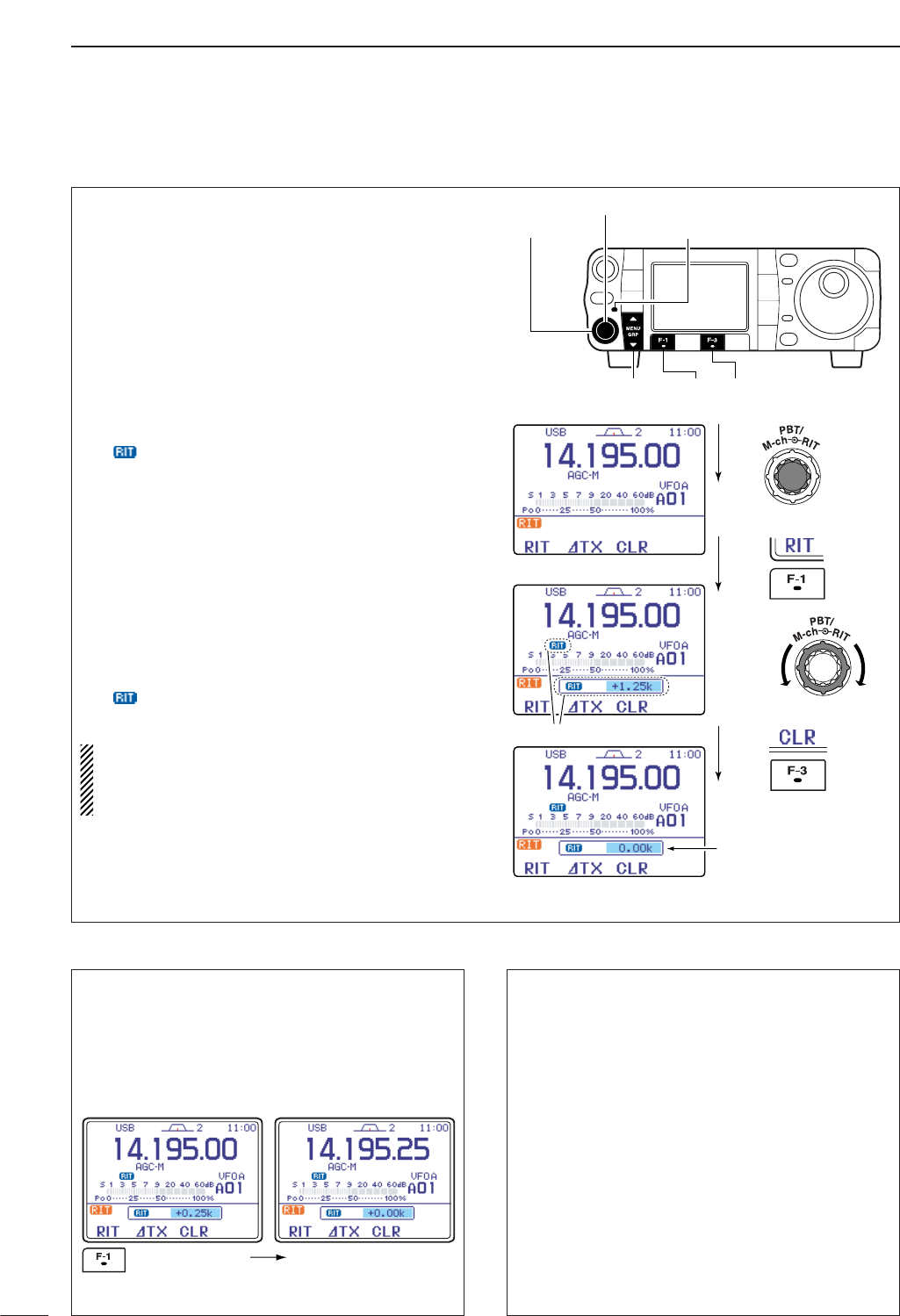
■RIT function
The RIT (Receive Incremental Tuning) function com-
pensates for communicating stations off-frequency.
The function shifts the receive frequency up to ±9.999
kHz in 1 Hz steps (10 Hz steps when cancelling the 1
Hz step readout) without moving the transmit fre-
quency.
qPush [PBT/M-ch/RIT] momentarily to select the M-
ch/RIT function, if the twin PBT is selected.
•[PBT/M-ch/RIT] indicator (Green) goes out.
wPush [PBT/M-ch/RIT] for 1 sec. to enter the
RIT/∂TX mode.
ePush [F-1 RIT]to turn the RIT function ON.
•“ ” indicator and the frequency shift appear and
[PBT/M-ch/RIT] indicator lights orange when the func-
tion is ON.
rRotate [RIT] (outer) control to compensate for off-
frequency stations.
•The transmit frequency is not shifted.
tTo reset the RIT frequency, push [F-3 CLR]for 1
sec.
•Push [F-3 CLR]momentarily to reset the RIT fre-
quency when “Quick RIT/∂TX Clear” in the
miscellaneous (others) set mode is ON. (p. 135)
yTo cancel the RIT function, push [F-1 RIT]mo-
mentarily again.
• “ ” indicator disappears.
uPush [Z(
MENU
/
GRP
)] to exit the RIT/∂TX mode.
When RIT and ∂TX are ON at the same time, the
[RIT] (outer) control shifts both the transmit and re-
ceive frequencies from the displayed frequency at
the same time.
Push
Push
Rotate
Push for 1sec.
Appear
Reset to
“0.00k”
[MENU/GRP] [F-1] [F-3]
[PBT/M-ch/RIT] indicator
[PBT/M-ch/RIT] switch
[RIT] (outer)
75
5FUNCTIONS FOR RECEIVE
• Calculate function
The shift frequency of the RIT (or ∂TX) function can
be added/subtracted to the displayed frequency.
While displaying the RIT (and/or ∂TX) shift fre-
quency, push and hold [F-1 RIT](or [F-2 ∂TX]) for
1 sec.
• Practical example
When you find a DX station on 21.025 MHz/CW and
the station is picking up stations transmitting slightly
up from 21.025 MHz.
qPush [F-1 RIT]and [F-2 ∂TX]to turn both the
RIT and ∂TX functions ON.
wRotate [RIT] (outer) to find the DX station’s re-
ceive frequency.
eWhen you find the DX station’s receive frequency,
push [F-1 RIT]to turn the RIT function OFF.
•Now you can transmit the DX station’s receive fre-
quency and receive on the DX station’s transmit fre-
quency (21.025 MHz).
rStart transmitting when the station stands by for
new callers.
Push and hold
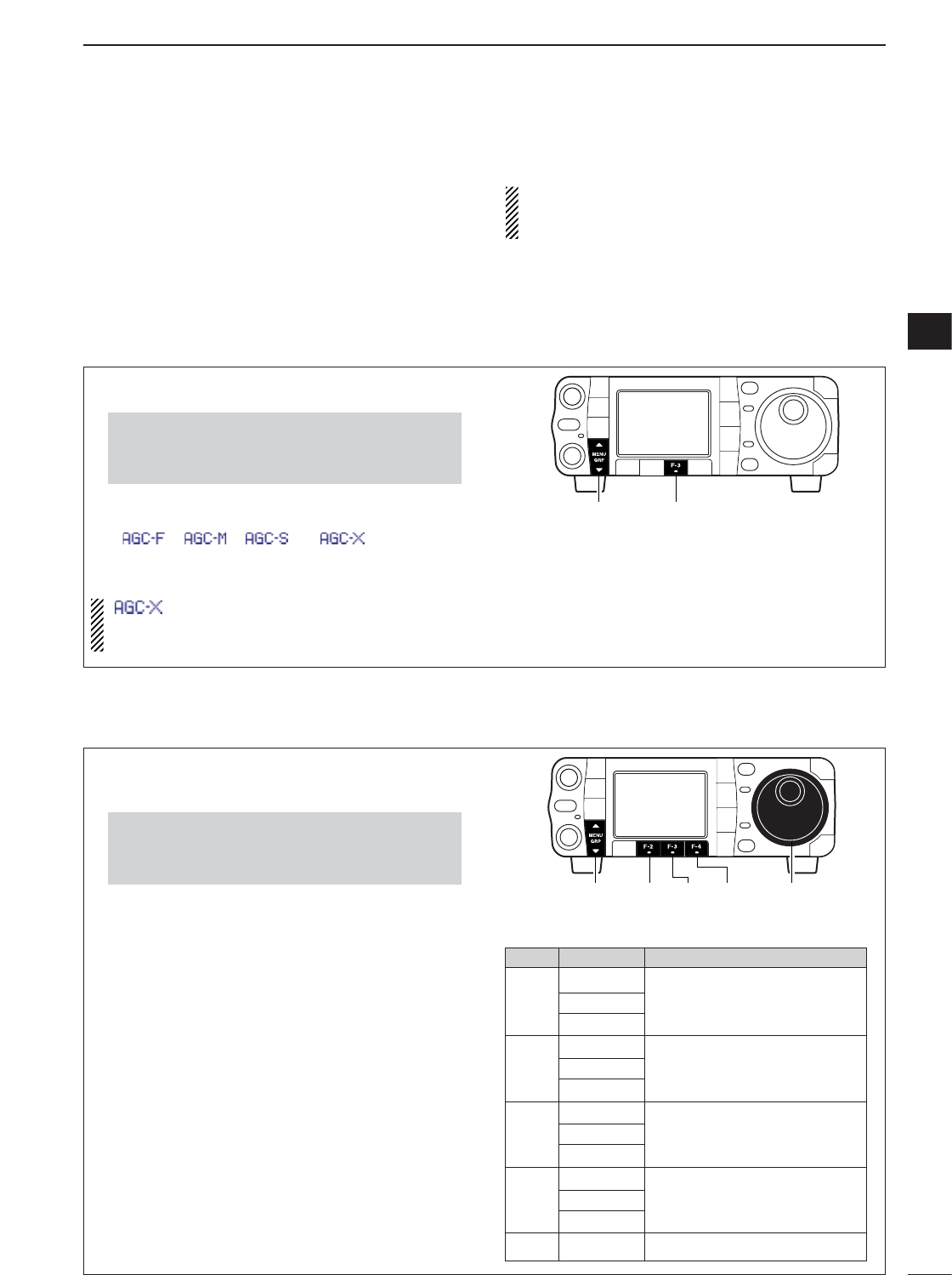
DSetting the AGC time constant
76
5
FUNCTIONS FOR RECEIVE
5
■AGC function
The AGC (auto gain control) controls receiver gain to
produce a constant audio output level even when the
received signal strength is varied by fading, etc.
The transceiver has 3 AGC characteristics (time con-
stant; fast, mid, slow) for non-FM/WFM mode.
The FM/WFM modes AGC time constant is fixed as
‘FAST’ (0.1 sec.) and AGC time constant cannot be
selected.
qSelect non-FM/WFM mode with [MODE].
wSelect M
-
3.
ePush [F-3 AGC]several times to select AGC fast,
AGC medium (MID) AGC slow or AGC OFF.
• “ ,” “ ,” “ ” or “ ” appears when
AGC fast, AGC medium (MID), AGC slow or AGC OFF
is selected, respectively.
“ ” (OFF) appears when AGC time constant
OFF is set with one of FAST, MID, SLOW setting
in AGC set mode.
[MENU/GRP] [F-3]
•Push and hold [MENU/GRP] for 1 sec. once or twice
to select the menu group M.
•Push [MENU/GRP] momentarily one or more times to
select the menu M
-
3.
DAGC time constant selection
qSelect the desired mode other than FM/WFM
modes.
wSelect M
-
3.
ePush [F-3 AGC]for 1 sec. to enter the AGC set
mode.
rPush one of [F-2 FAST],[F-3 MID],[F-4 SLOW]
to select the desired AGC time constant.
tRotate [DIAL] to set the desired time constant.
•AGC time constants can be selected between 0.1 to
8.0 sec. (depends on mode) or turned OFF.
•Push and hold [F-2 FAST],[F-3 MID]or [F-4 SLOW]
for 1 sec. to select a default value each for fast, mid.
and slow, respectively.
ySelect another mode other than FM/WFM. Repeat
steps rand t, if desired.
•See table to the right for available tone frequencies.
uPush [Z(
MENU
/
GRP
)] to exit the AGC set mode.
• Selectable AGC time constant (unit: sec.)
[MENU/GRP] [DIAL][F-3] [F-4][F-2]
•Push and hold [MENU/GRP] for 1 sec. once or twice
to select the menu group M.
•Push [MENU/GRP] momentarily one or more times to
select the menu M
-
3.
Mode Default Selectable AGC time constant
0.3 (FAST) OFF, 0.1, 0.2, 0.3, 0.5, 0.8, 1.2,
SSB 2.0 (MID) 1.6, 2.0, 2.5, 3.0, 4.0, 5.0, 6.0
6.0 (SLOW)
0.1 (FAST) OFF, 0.1, 0.2, 0.3, 0.5, 0.8, 1.2,
CW 0.5 (MID) 1.6, 2.0, 2.5, 3.0, 4.0, 5.0, 6.0
1.2 (SLOW)
0.1 (FAST) OFF, 0.1, 0.2, 0.3, 0.5, 0.8, 1.2,
RTTY 0.5 (MID) 1.6, 2.0, 2.5, 3.0, 4.0, 5.0, 6.0
1.2 (SLOW)
3.0 (FAST) OFF, 0.3, 0.5, 0.8, 1.2, 1.6, 2.0,
AM 5.0 (MID) 2.5, 3.0, 4.0, 5.0, 6.0, 7.0, 8.0
7.0 (SLOW)
FM/WFM
0.1 (FAST) Fixed
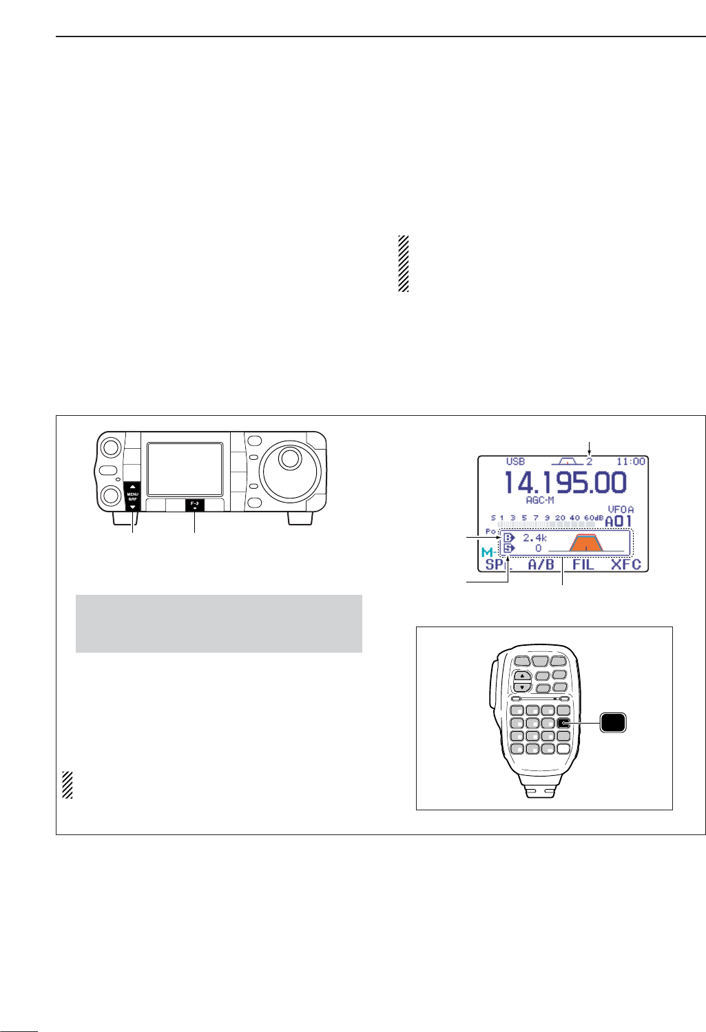
DIF filter selection
77
5FUNCTIONS FOR RECEIVE
■IF filter selection
The transceiver has 3 passband width IF filters for
each mode.
For SSB and CW modes, the passband width can be
set from 50 to 3600 Hz in 50 or 100 Hz steps. A total of
41 passband widths are available.
For RTTY mode, the passband width can be set from
50 to 2700 Hz in 50 or 100 Hz steps. A total of 32
passband widths are available.
For AM mode, the passband width can be set from 200
Hz to 10 kHz in 200 Hz steps. A total of 50 passband
widths are available.
For FM mode, the passband width is fixed and 3 pass-
band widths are available.
For WFM mode, the passband width is fixed at 280
kHz.
The filter selection is automatically memorized in
each mode.
The PBT shift frequencies are automatically memo-
rized in each filter.
qSelect the desired mode.
wSelect M
-
1.
ePush [F-3 FIL]momentarily several times to se-
lect the IF filter 1, 2 or 3.
•The selected filter number is displayed in the LCD.
•The filter setting window appears and shows the se-
lected passband width and shift frequency. (The filter
setting window can be turned OFF in the display set
mode. (p. 127)
The IF filter for WFM mode is fixed and cannot be
changed.
SPCH
/LOCK
TUNER
/CALL XFC
V/M
F-1 F-2
FIL
MODE
GENE
MW
123
456
789
.0CE
F-INP
ENT
1.8 3.5 7
10 14 18
21 24 28
50 144 430
HM-151
FIL
Passband
width
Selected IF filter
Shift
frequency Popup indicator appears
•Push and hold [MENU/GRP] for 1 sec. once or twice
to select the menu group M.
•Push [MENU/GRP] momentarily one or more times to
select the menu M
-
1.
[MENU/GRP] [F-3]
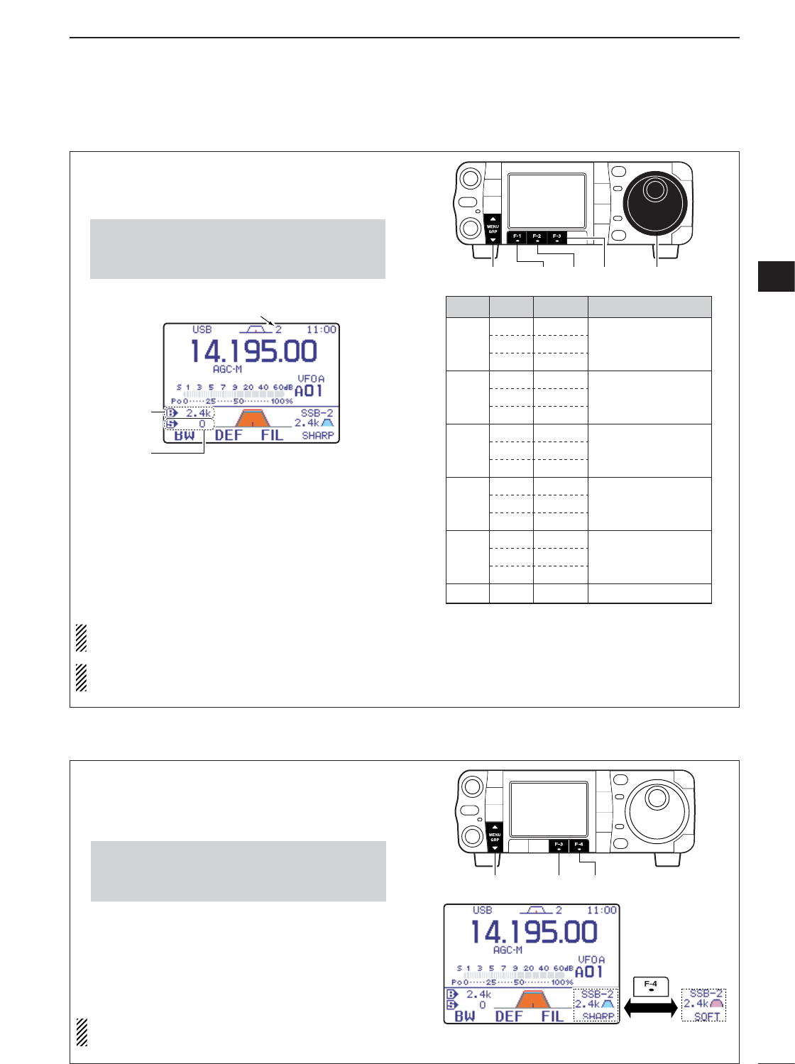
78
5
FUNCTIONS FOR RECEIVE
5
qSelect SSB, CW, RTTY or AM mode.
•Passband widths for FM and WFM modes are fixed
and cannot be set.
wSelect M
-
1.
ePush [F-3 FIL]for 1 sec. to enter filter set mode.
rPush [F-3 FIL]several times to select the desired
IF filter.
tWhile pushing [F-1 BW], rotate [DIAL] to set the
desired passband width.
•The passband width can be set within the range as
shown in the table to the right.
•Push [F-2 DEF]for 1 sec. to select the default value.
yRepeat steps rto tif desired.
uPush [Z(
MENU
/
GRP
)] to exit the filter set mode.
The PBT shift frequencies are cleared when the
passband width is changed.
This filter set mode screen graphically displays the
PBT shift frequencies.
*: When the IF filter is selected FIL2 or FIL3 in the FM
mode operation, the Tx IF filter’s passband width is
fixed narrow selection (2.5 kHz).
FIL1
Mode Filter Default Range (Steps)
3.0 kHz
1.8 kHz
2.4 kHz
1.2 kHz
250 Hz
7.0 kHz
500 Hz
2.4 kHz
250 Hz
500 Hz
9.0 kHz
3.0 kHz
6.0 kHz
10 kHz Fixed
15 kHz
50–500 Hz (50 Hz)/
600–3.6 kHz (100 Hz)
50–500 Hz (50 Hz)/
600–3.6 kHz (100 Hz)
50–500 Hz (50 Hz)/
600–2.7 kHz (100 Hz)
200 Hz–10.0 kHz
(200 Hz)
FIL2
SSB
RTTY
AM
FM*
WFM
CW
FIL3
FIL1
FIL2
FIL3
FIL1
FIL2
FIL3
FIL1
FIL2
FIL3
FIL1
FIL2
280 kHz FixedFIL
FIL3
[MENU/GRP] [DIAL][F-2] [F-3][F-1]
Selected IF filter
Passband
width
Shift
frequency
•Push and hold [MENU/GRP] for 1 sec. once or twice
to select the menu group M.
•Push [MENU/GRP] momentarily one or more times to
select the menu M
-
1.
DFIlter passband width setting (SSB/CW/RTTY/AM only)
DIF fIlter shape (SSB/CW only)
The type of DSP filter shape for each SSB and CW
can be selected independently from soft and sharp.
qSelect SSB or CW mode.
wSelect M
-
1.
ePush [F-3 FIL]for 1 sec. to enter filter set mode.
rPush [F-3 FIL]several times to select the desired
IF filter.
tPush [F-4] to select the filter shape from “
SHARP
”
and “
SOFT
.”
yPush [Z(
MENU
/
GRP
)] to exit the filter set mode.
Specified selectivity (p. 150) is measured with this
parameter set to SHARP.
Push
[MENU/GRP] [F-3] [F-4]
•Push and hold [MENU/GRP] for 1 sec. once or twice
to select the menu group M.
•Push [MENU/GRP] momentarily one or more times to
select the menu M
-
1.
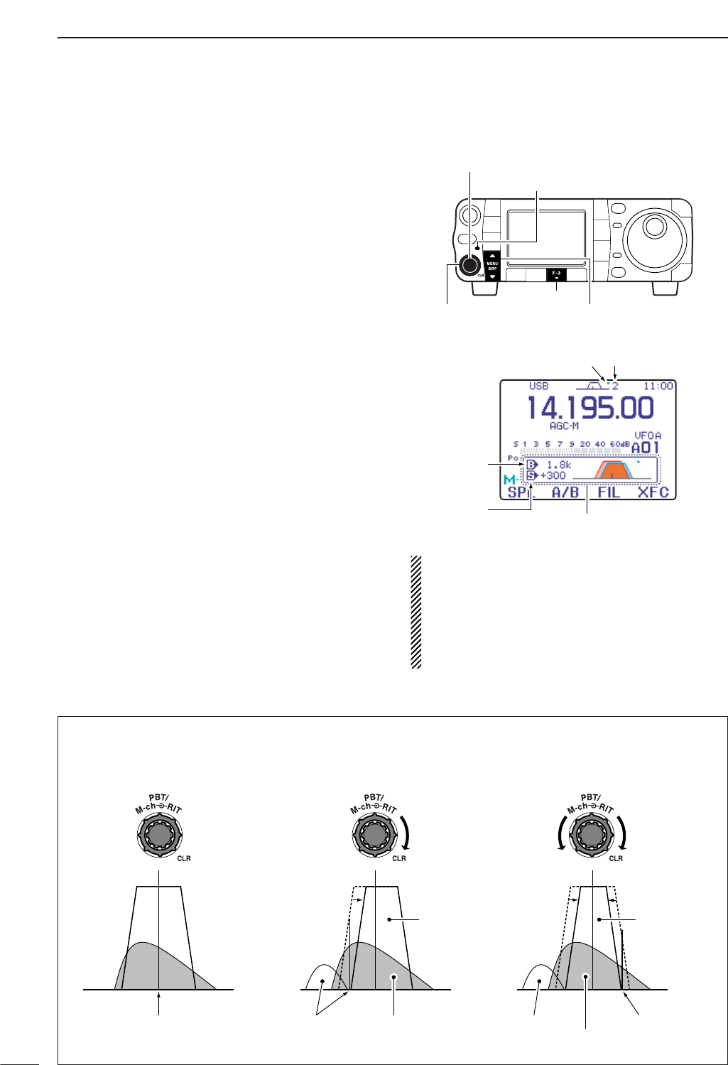
79
5FUNCTIONS FOR RECEIVE
General PBT (Passband Tuning) function electronically
narrows the IF passband width by shifting the IF fre-
quency to slightly outside of the IF filter passband to
reject interference. This transceiver uses the DSP cir-
cuit for the PBT function. Moving both [PBT/M-ch/RIT]
controls to the same position shifts the IF.
➥Push [PBT/M-ch/RIT] momentarily to select the
twin PBT function, if the M-ch-RIT is selected.
•[PBT/M-ch/RIT] indicator (Green) lights.
• The passband settings window shows the passband
width and shift frequency graphically. (The passband
settings window can be turned OFF in the display set
mode. p. 127)
➥When M
-
1is selected, push [F-3 FIL]for 1 sec. to
enter the filter set mode. Current passband width
and shift frequency is displayed in the filter set
mode.
➥To set the [PBT/M-ch/RIT]controls to the center posi-
tions, push [PBT/M-ch/RIT(
CLR
)] for 1 sec.
The limit of the variable range depends on the pass-
band width and mode. The edge of the variable range
is half of the passband width, and PBT is adjustable in
100 (AM) or 25 Hz steps (other modes).
•[PBT] controls should normally be set to the center posi-
tions (PBT setting is cleared) when there is no interfer-
ence.
•When PBT is used, the audio tone may be changed.
• Not available for FM or WFM modes.
•While rotating [PBT], noise may occur. This comes from
the DSP unit and does not indicate an equipment mal-
function.
Passband
width
Selected IF filter
Shift
frequency Popup indicator appears
Dot indicator appears
when PBT is activate
[MENU/GRP]
[F-3]
[PBT/M-ch/RIT] indicator
[PBT/M-ch/RIT(CLR)] switch/[PBT] (inner) control
[PBT] (outer) control
PBT OPERATION EXAMPLE
IF center frequency Interference Desired signal
Passband
Both controls at
center position
Cutting a lower
passband
Cutting both higher and
lower passbands
Interference Interference
Desired signal
Passband
■Twin PBT operation
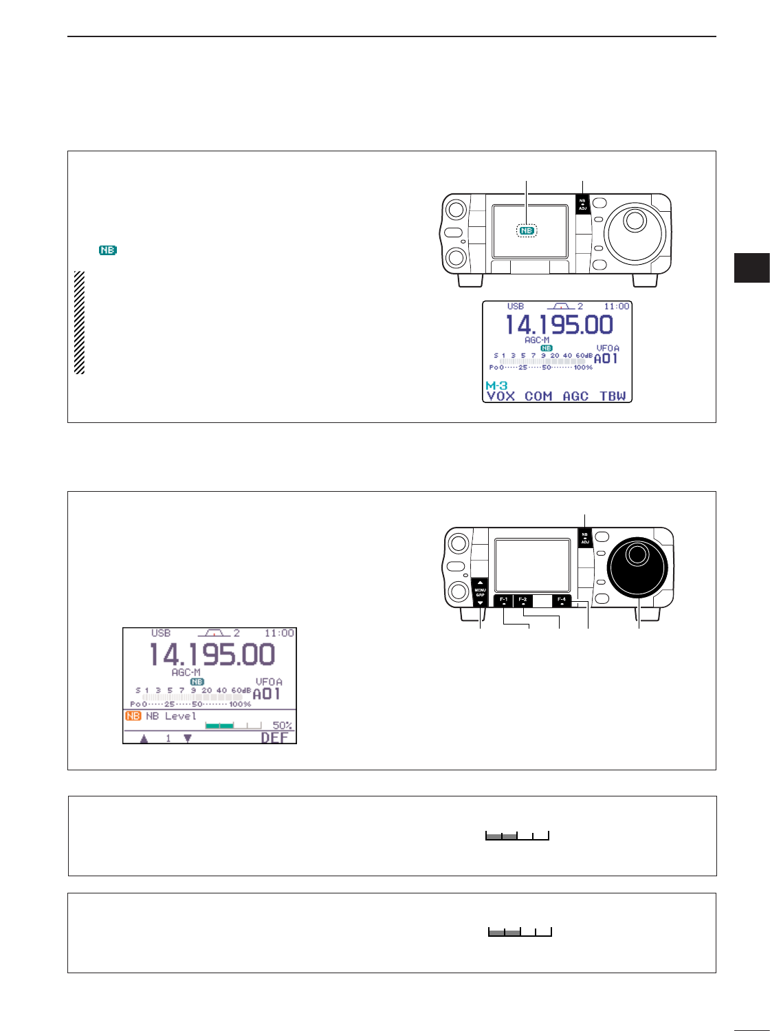
80
5
FUNCTIONS FOR RECEIVE
5
DNoise blanker set mode
■Noise blanker
The noise blanker eliminates pulse-type noise such
as from car ignitions. The noise blanker is not avail-
able for WFM mode.
➥Push [NB/ADJ] momentarily to toggle the noise
blanker ON and OFF.
• “ ” indicator appears when the NB function is ON.
When using the noise blanker, received signals
may be distorted if they are excessively strong or
the noise type is other than impulse. Nearby strong
signals can also cause the noise blanker created
distortion. Turn the noise blanker function OFF, or
adjust the noise blanker level to shallow position
(see below) in this case.
[NB/ADJ]
Appears
qPush and hold [NB/ADJ] for 1 sec. to enter the
noise blanker set mode.
wPush [F-1 ≤]or [F-2 ≥]to select the desired set
item.
eRotate [DIAL] to adjust the desired condition.
•Push [F-4 DEF]for 1 sec. to return to default value.
rPush [NB/ADJ] (or push [Z(
MENU
/
GRP
)]) to exit the
noise blanker set mode.
[MENU/GRP]
[NB/ADJ]
[F-1] [F-2] [F-4] [DIAL]
1. NB Level
This item adjusts the noise blanker level. The noise
blanker level can be adjusted from 0 to 100%.
50%
50% (default)
2. NB Width
This item adjusts the noise blanker width. The noise
blanker width can be adjusted from 1 to 100.
50
50 (default)
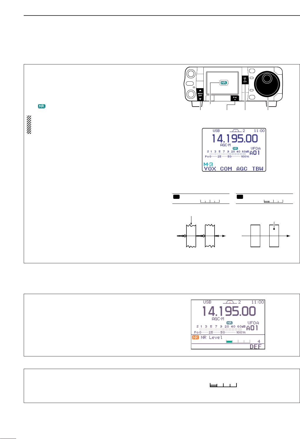
81
5FUNCTIONS FOR RECEIVE
■Noise reduction
The noise reduction function enhances desired sig-
nals in the presence of noise by using the DSP cir-
cuit. The amount of enhancement is adjustable.
➥Push [NR/LEV] momentarily to toggle the noise re-
duction ON and OFF.
• “ ” indicator appears when the NR function is ON.
The noise reduction level can result in audio signal
masking. Set the noise reduction level for maxi-
mum readability as described below.
Noise reduction OFF Noise reduction activated
Desired
signal (CW)
Noise components
0
NR Level
NR 5
NR Level
NR
[MENU/GRP] [NR/LEV][F-4] [DIAL]
Appears
NR Level
This item adjusts the noise reduction level. The noise
reduction level can be adjusted from 0 to 15.
4
4 (default)
DNoise reduction set mode
qPush [NR/LEV] for 1 sec. to enter the noise reduc-
tion level set mode.
wRotate [DIAL] to adjust the noise reduction level.
• Set the noise reduction level 0 to 15.
•Push [F-4 DEF]for 1 sec. to return to default level.
ePush [NR/LEV] (or push [Z(
MENU
/
GRP
)]) to exit the
noise reduction level set mode.
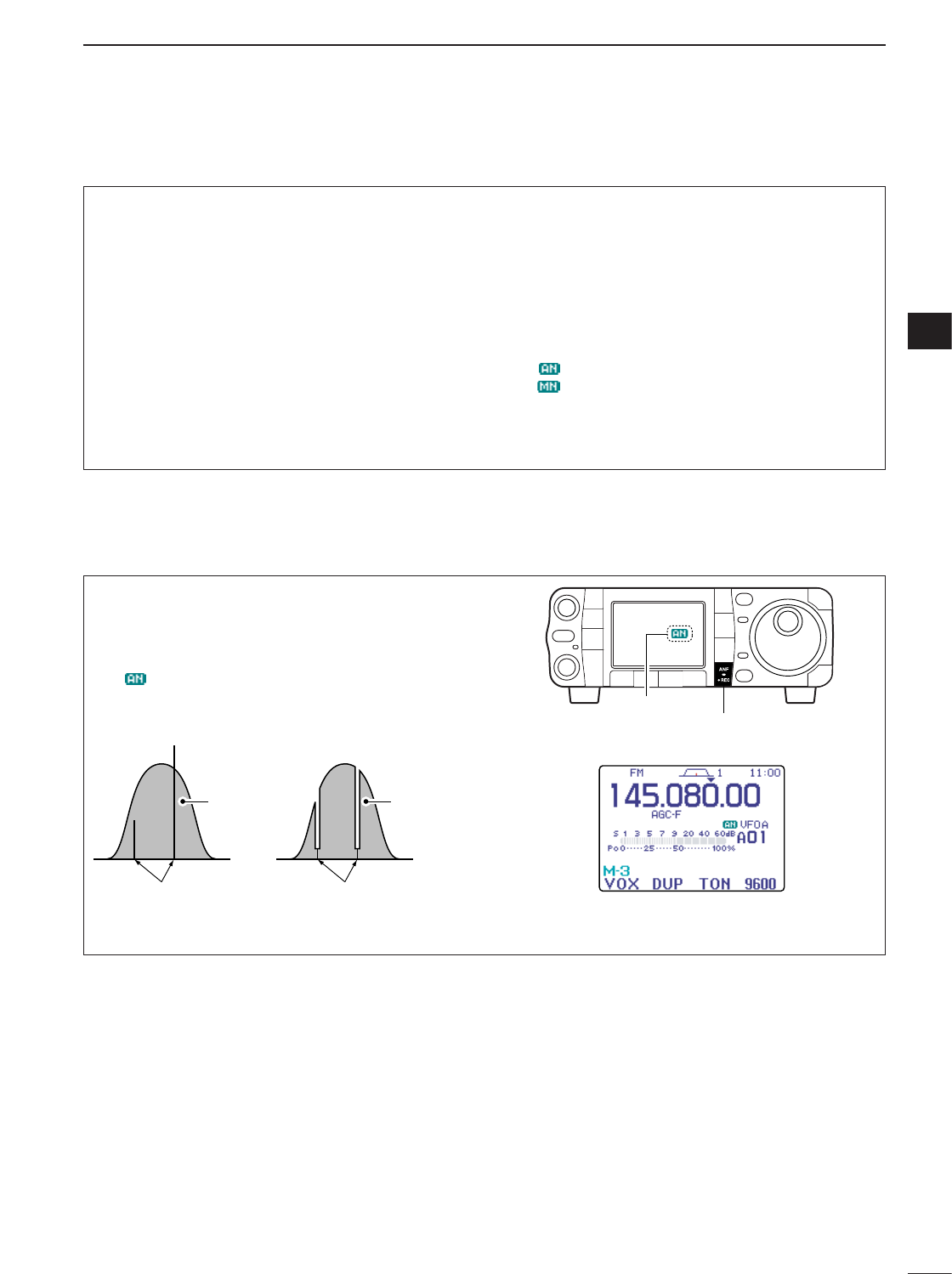
82
5
FUNCTIONS FOR RECEIVE
5
DAuto notch function
■Notch function
This transceiver has auto and manual notch func-
tions. The auto notch function automatically attenu-
ates up to 3 beat tones, tuning signals, etc., even if
they are moving. The manual notch can be set to at-
tenuate a frequency via the manual notch filter set
mode.
➥While in SSB and AM modes, push [ANF/•REC] or
[MNF/ADJ] to toggle the notch function between
auto, manual and OFF.
• Both of the auto and manual notch functions can be ac-
tivate at the same time.
➥While in CW and RTTY modes, push [MNF/ADJ]
to toggle the manual notch function ON and OFF.
➥While in FM and WFM modes, push [ANF/•REC]
to toggle the auto notch function ON and OFF.
• “ ” appears when auto notch function is in use.
• “ ” appears when manual notch function is in use.
•Manual notch filter settings are described on the next
page.
The auto notch can be used in SSB, AM, FM and
WFM modes.
➥Push [ANF/•REC] momentarily to turn the auto-
matic notch function ON and OFF.
• “ ” appears when auto notch function is in use.
[ANF/•REC]
Appears
Unwanted frequency
is attenuated
Desired
signal (AF)
Desired
signal (AF)
Particular frequency
is attenuated
Auto notch OFF Auto notch ON
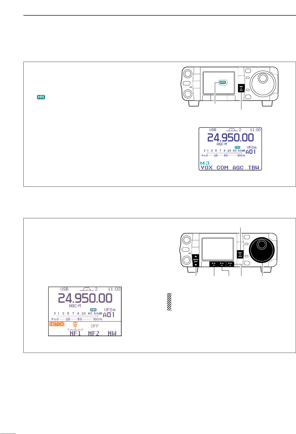
DManual notch function
83
5FUNCTIONS FOR RECEIVE
qPush [MNF/ADJ] for 1 sec. to enter the manual
notch filter set mode.
wPush [F-2 NF1]or [F-3 NF2]to select the desired
filter ON and OFF.
eRotate [DIAL] to adjust the selected filter fre-
quency.
•Push [F-4 NW]to toggle the filter width from narrow,
middle and wide.
rPush [MNF/ADJ] (or push [Z(
MENU
/
GRP
)]) to exit
the manual notch filter set mode.
While adjusting the manual notch filter, noise may
be heard. This comes from the DSP unit and does
not indicate an equipment malfunction.
[MENU/GRP]
[MNF/ADJ]
[F-2] [F-3] [F-4] [DIAL]
The manual notch function can be used in SSB, CW,
RTTY and AM modes.
➥Push [MNF/ADJ] momentarily to turn the manual
notch function ON and OFF.
• “ ” appears when manual notch function is in use.
•Set the frequency for manual notch filtering via the
manual notch filter set mode. (shown below)
•Even when both of the manual notch filters, “NF1” and
“NF2,” are set to OFF in the manual notch filter set
mode, “NF1” is automatically turned ON if the manual
notch function is ON.
[MNF/ADJ]
Appears
DManual notch filter set mode
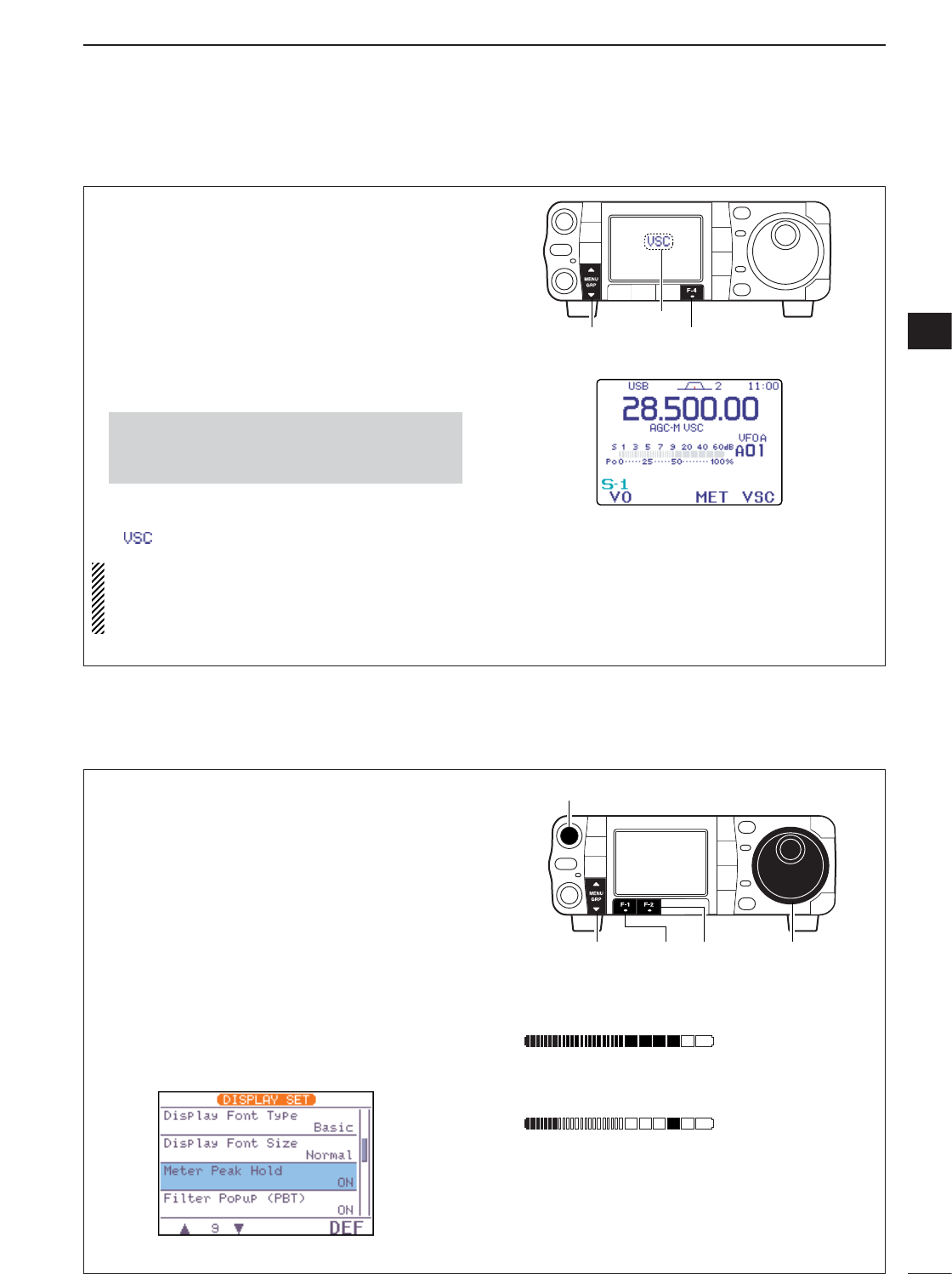
84
5
FUNCTIONS FOR RECEIVE
5
■Meter peak hold function
The S-meter has a peak level holding function. The
peak level of the received signal strength is indicated
for 0.5 sec. (approx). This function can be deactivated
in the display set mode (“Meter Peak Hold” ;
see p. 127) if desired.
qPush [AF(
SET
)] momentarily to enter the set mode
menu.
wPush [F-2 DISP]to enter the display set mode.
ePush [F-1 ≤]or [F-2 ≥]to select “Meter Peak
Hold.”
rRotate [DIAL] to turn the meter peak hold setting
ON and OFF.
•Push [F-4 DEF]for 1 sec. to return to default condition.
tPush [Z(
MENU
/
GRP
)] twice to return to normal op-
erating mode.
Initial reception of a
signal results in an
S-meter reading of
40 dB.
The highest indica-
ted bar remains dis-
played for about 0.5
sec. even when the
signal strength de-
creases.
[EXAMPLE]:
S 7 60dB40209531
S 7 60dB40209531
[MENU/GRP] [F-2][F-1] [DIAL]
[AF]
■Voice squelch control function
This function is useful when you don't want to hear
unmodulated signals. When the voice squelch control
function is activated, the transceiver checks received
signals for voice components.
If a receiver signal includes voice components, and
the tone of the voice components changes within 1
sec., squelch opens. If the received signal includes
no voice components or the tone of the voice compo-
nents does not change within 1 sec., squelch closes.
qSelect S
-
1or S
-
2.
wPush [F-4 VSC]to turn the VSC (Voice Squelch
Control) function ON.
•“ ” appears when the function is activated.
•The VSC function is available for phone modes
(SSB, AM, FM, WFM).
•The VSC function can also be used for scanning
operation in AM, FM or WFM modes. (p. 114)
[MENU/GRP] [F-4]
Appears
•Push and hold [MENU/GRP] for 1 sec. once or twice
to select the menu group S.
•Push [MENU/GRP] momentarily one or more times to
select the menu S
-
1or S
-
2.
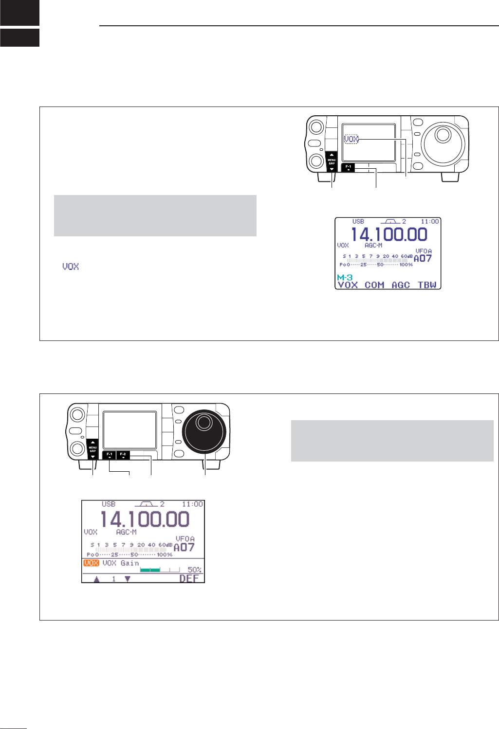
6
85
FUNCTIONS FOR TRANSMIT
DAdjusting the VOX function
■VOX function
The VOX (Voice-Operated Transmission) function
switches between transmit and receive with your
voice. This function provides an opportunity for
hands-free operation or to input log entries into your
computer, etc., while operating.
qSelect a phone mode (SSB, AM, FM) with [MODE].
wSelect M
-
3.
ePush [F-1 VOX]to toggle the VOX function ON
and OFF.
•“ ” appears while the VOX is in use.
The VOX gain, ANTI-VOX and VOX delay can be set in
VOX set mode.
[MENU/GRP] [F-1]
Appears
•Push and hold [MENU/GRP] for 1 sec. once or twice
to select the menu group M.
•Push [MENU/GRP] momentarily one or more times to
select the menu M
-
3.
qSelect a phone mode (SSB, AM, FM).
wSelect M
-
3.
ePush [F-1 VOX]for 1 sec. to enter the VOX set
mode.
rSelect the VOX gain item using [F-1 ≤]or [F-2 ≥].
tWhile speaking into the microphone, rotate [DIAL]
to the point where the transceiver is continuously
transmitting.
yAdjust the VOX delay for a convenient interval be-
fore returning to receive.
- Select the VOX delay item using [F-1 ≤]or [F-2 ≥].
- Rotate [DIAL].
uIf the receive audio from the speaker causes the
VOX circuit to switch to, adjust the anti VOX to the
point where it has no effect.
•Push and hold [MENU/GRP] for 1 sec. once or twice
to select the menu group M.
•Push [MENU/GRP] momentarily one or more times to
select the menu M
-
3.
[MENU/GRP] [F-2] [DIAL][F-1]
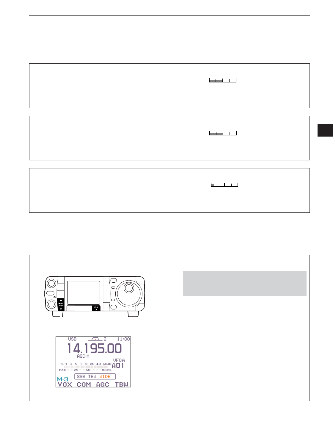
DVOX set mode
86
6
FUNCTIONS FOR TRANSMIT
6
3. VOX Delay
This item adjusts the VOX (Voice-activated Transmit)
delay time. The delay time can be adjusted from 0 to
2.0 sec. in 0.1 sec. steps.
•Push [F-4 DEF]for 1 sec. to return to default delay time.
0.2s
0.2 sec. (default)
1. VOX Gain
This item adjusts the VOX gain for the VOX (voice ac-
tivated transmit) function.
This setting can be adjusted
from 0 to 100% in 1% steps.
•Push [F-4 DEF]for 1 sec. to return to default gain.
50%
50% (default)
2. Anti-VOX
This item adjusts the ANTI-VOX gain for the VOX
(voice activated transmit) function.
This setting can be
adjusted from 0 to 100% in 1% steps.
•Push [F-4 DEF]for 1 sec. to return to default gain.
50%
50% (default)
■Transmit filter width setting (SSB only)
The transmit filter width for SSB mode can be se-
lected from wide, middle and narrow.
qSelect an SSB mode (USB or LSB) with [MODE].
wSelect M
-
3.
ePush and hold [F-4 TBW]for 1 sec. once or twice
to select the desired transmit filter width from nar-
row, middle and wide.
•Push [F-4 TBW]momentarily to indicate the selected
TX filter width.
•The transmit filter width window appears for showing
the selected TX filter width each time [F-4 TBW].
•The following filters are specified as the default. Each
of the filter widths can be set in the quick set mode.
(pgs. 123, 124)
WIDE : 100 Hz to 2900 Hz
MID : 300 Hz to 2700 Hz
NAR : 500 Hz to 2500 Hz
•Push and hold [MENU/GRP] for 1 sec. once or twice
to select the menu group M.
•Push [MENU/GRP] momentarily one or more times to
select the menu M
-
3.
[MENU/GRP] [F-4]
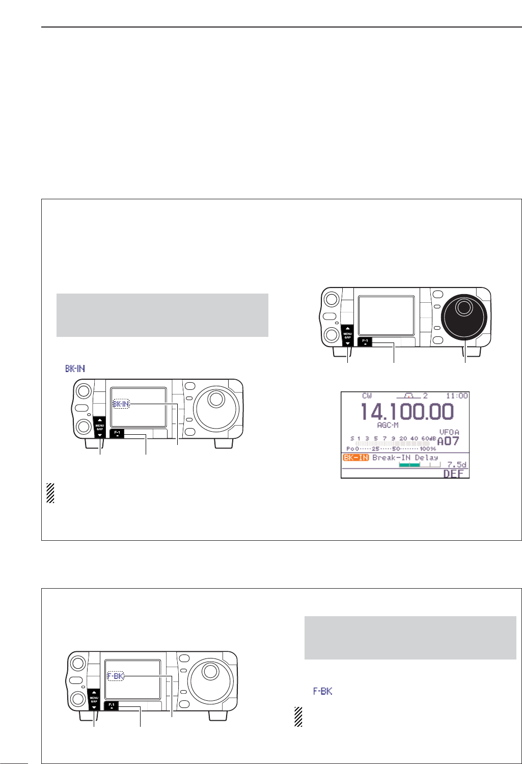
87
6FUNCTIONS FOR TRANSMIT
DFull break-in operation
DSemi break-in operation
■Break-in function
During semi break-in operation, the transceiver se-
lects transmit when keying, then automatically returns
to receive after a pre-set time from when you stop
keying.
• Semi break-in operation
qPush [MODE] to select CW or CW-R mode.
wSelect M
-
3.
ePush [F-1 BRK]once or twice to turn the semi
break-in function ON.
•“”appears.
When using a paddle, set “Key Speed” in the
quick set mode to adjust the keying speed. (p. 124)
• Break-in delay setting
qPush [MODE] to select CW or CW-R mode.
wSelect M
-
3.
ePush [F-1 BRK]for 1 sec. to enter the break-in
delay time set mode.
rRotate [DIAL] to set the break-in delay time (the
delay from transmit to receive).
[MENU/GRP] [F-1] [DIAL]
[MENU/GRP] [F-1]
Appears
•Push and hold [MENU/GRP] for 1 sec. once or twice
to select the menu group M.
•Push [MENU/GRP] momentarily one or more times to
select the menu M
-
3.
During full break-in operation, the transceiver auto-
matically switches to receive between keying dots
and dashes so that the operator can hear activity on
the channel when transmitting.
qPush [MODE] to select CW or CW-R mode.
wSelect M
-
3.
ePush [F-1 BRK]once or twice to turn the semi
break-in function ON.
•“”appears.
When using a paddle, set “Key Speed” in the
quick set mode to adjust the keying speed. (p. 124)
•Push and hold [MENU/GRP] for 1 sec. once or twice
to select the menu group M.
•Push [MENU/GRP] momentarily one or more times to
select the menu M
-
3.
[MENU/GRP] [F-1]
Appears
The break-in function is used in CW mode to automat-
ically switch the transceiver between transmit and re-
ceive when keying. The IC-7000 is capable for full
break-in or semi break-in.
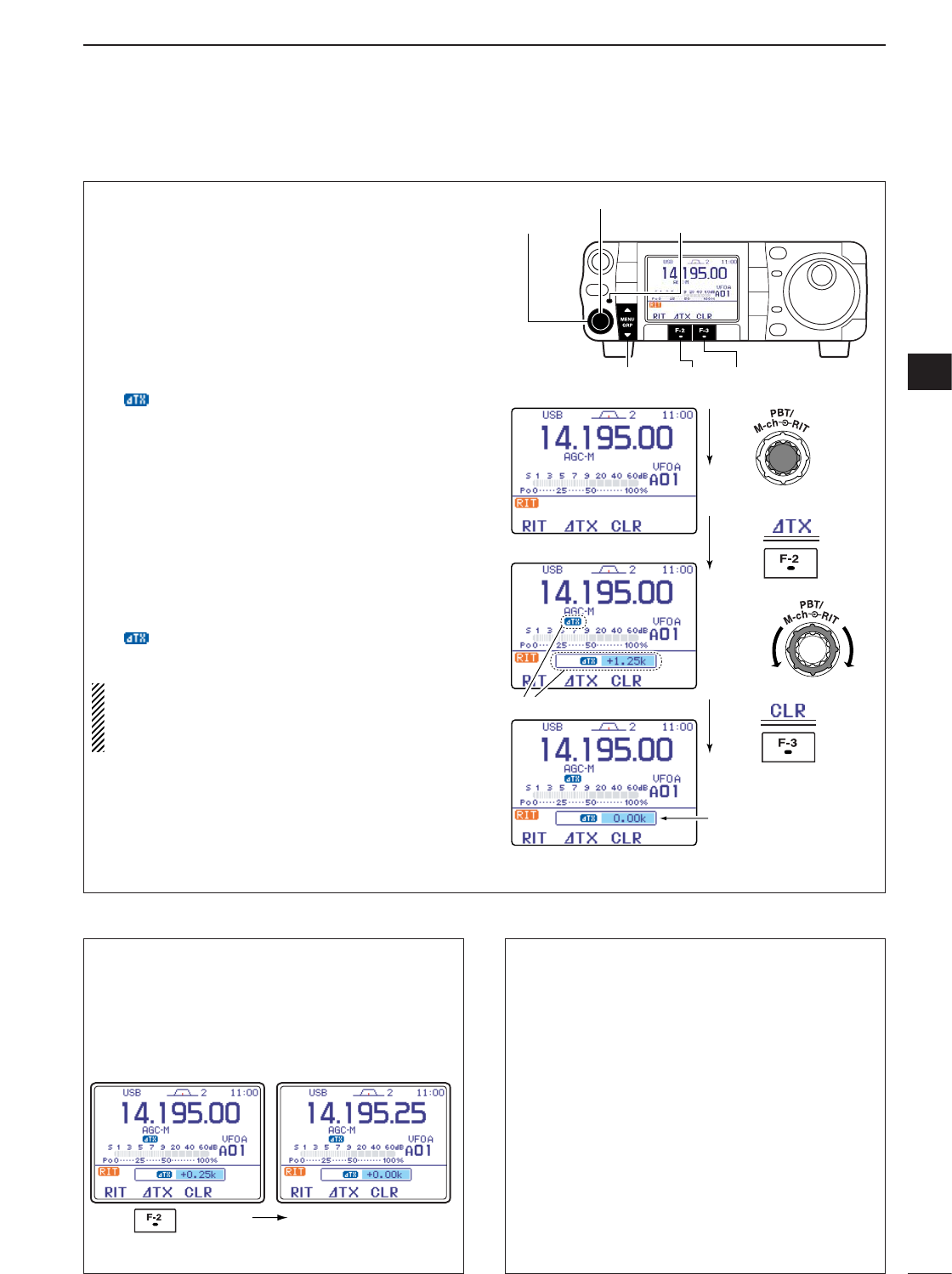
88
6
FUNCTIONS FOR TRANSMIT
6
■∂TX function
The ∂TX function shifts the transmit frequency up to
±9.999 kHz in 1 Hz steps (10 Hz steps when can-
celling the 1 Hz step readout) without moving the re-
ceive frequency.
qPush [PBT/M-ch/RIT] momentarily to select the M-
ch/RIT function, if the twin PBT is selected.
•[PBT/M-ch/RIT] indicator (Green) goes out.
wPush [PBT/M-ch/RIT] for 1 sec. to enter the
RIT/∂TX mode.
ePush [F-2 ∂TX]to turn the ∂TX function ON.
•“ ” indicator and the frequency shift appear and
[PBT/M-ch/RIT] indicator lights orange when the func-
tion is ON.
rRotate [RIT] (outer) control to shift the transmitter
frequency.
•The receive frequency is not shifted.
tTo reset the ∂TX frequency, push [F-3 CLR]for
1 sec.
•Push [F-3 CLR]momentarily to reset the RIT fre-
quency when “Quick RIT/∂TX Clear” in the
miscellaneous (others) set mode is ON. (p. 135)
yTo cancel the ∂TX function, push [F-2 ∂TX]mo-
mentarily again.
• “ ” indicator disappears.
uPush [Z(
MENU
/
GRP
)] to exit the RIT/∂TX mode.
When RIT and ∂TX are ON at the same time,
[RIT] (outer) control shifts both the transmit and re-
ceive frequencies from the displayed frequency at
the same time.
Push for 1sec.
Push
Push
Rotate
Appear
Reset to
“0.00k”
[MENU/GRP] [F-2] [F-3]
[PBT/M-ch/RIT] indicator
[PBT/M-ch/RIT] switch
[RIT] (outer)
• Calculate function
The frequency shift of the (RIT or) ∂TX function can
be added/subtracted to the displayed frequency.
While displaying the (RIT and/or) ∂TX shift fre-
quency, push and hold ([F-1 RIT]or) [F-2 ∂TX]for
1 sec.
• Practical example
When you find a DX station on 21.025 MHz/CW and
the station is picking up stations transmitting slightly
up from 21.025 MHz.
qPush [F-1 RIT]and [F-2 ∂TX]to turn both the
RIT and ∂TX functions ON.
wRotate [RIT] (outer) to find the DX station’s re-
ceive frequency.
eWhen you find the DX station’s receive frequency,
push [F-1 RIT]to turn the RIT function OFF.
•Now you can transmit the DX station’s receive fre-
quency and receive the DX station’s transmit fre-
quency (21.025 MHz).
rStart transmitting while the station is standing by.
Push and hold
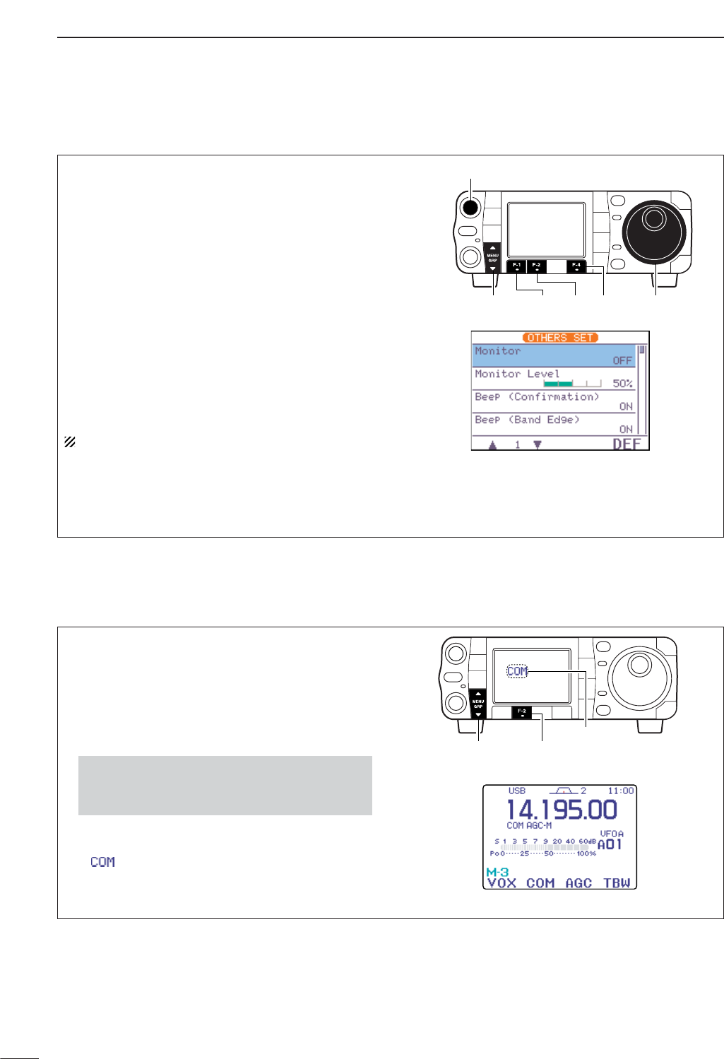
89
6FUNCTIONS FOR TRANSMIT
The IC-7000 has a built-in, low distortion speech com-
pressor circuit. This circuit increases your average
talk power in SSB mode and is especially useful for
DX’ing when the receiving station is having difficulty
copying your signal.
qSelect an SSB mode.
wSelect M
-
3.
ePush [F-2 COM]momentarily to turn the speech
compressor function ON and OFF.
•“ ” appears.
[MENU/GRP] [F-2]
Appears
•Push and hold [MENU/GRP] for 1 sec. once or twice
to select the menu group M.
•Push [MENU/GRP] momentarily one or more times to
select the menu M
-
3.
■Speech compressor
■Monitor function
The monitor function allows you to monitor your trans-
mitted signals at the IF in any mode through the
speaker. The CW side tone functions regardless of
the monitor function setting.
qPush [AF(
SET
)] momentarily to enter the set mode
menu.
wPush [F-4 OTH]to enter the miscellaneous (oth-
ers) set mode.
ePush [F-1 ≤]several times to select “Monitor.”
rRotate [DIAL] to turn the monitor function ON.
•Push [F-4 DEF]for 1 sec. to return to default condition.
tPush [F-2 ≥]to select “Monitor Level.”
yRotate [DIAL] to adjust the monitor level.
•Push [F-4 DEF]for 1 sec. to return to default level.
uPush [Z(
MENU
/
GRP
)] twice to return to normal op-
erating mode.
Use headphones to prevent feedback.
[MENU/GRP] [DIAL]
[AF]
[F-4][F-1] [F-2]
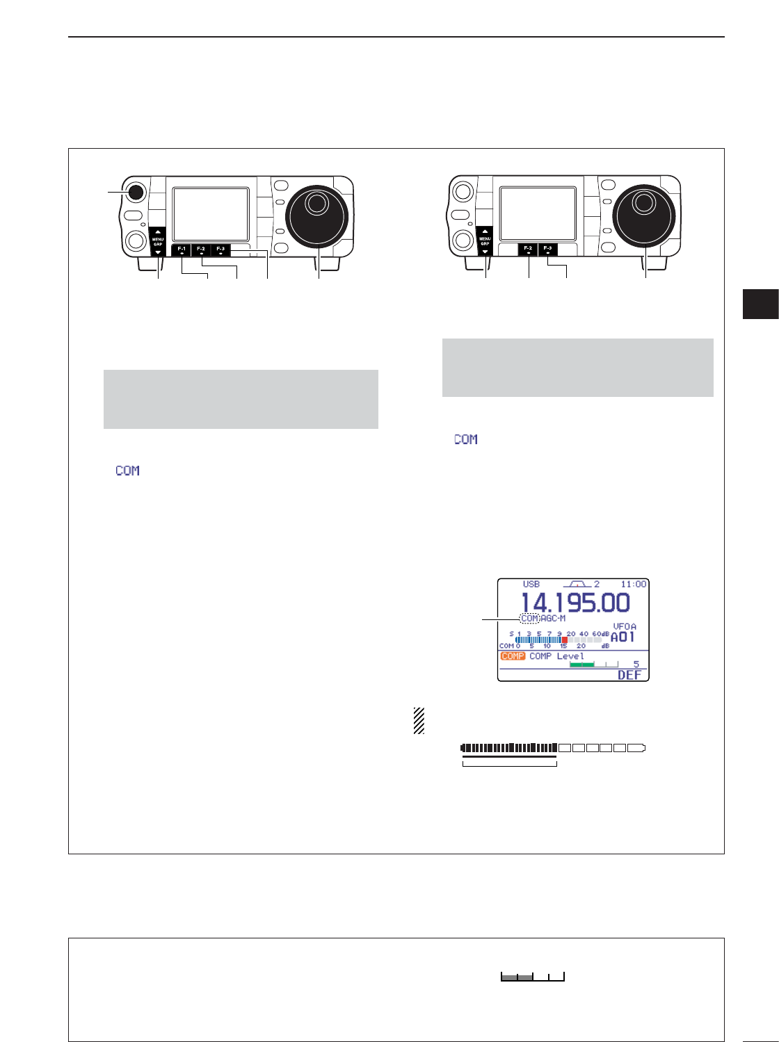
90
6
FUNCTIONS FOR TRANSMIT
6
COMP Level
This item adjusts the speech compression level. The
speech compression level can be adjusted from 0 to
10.
•Push [F-4 DEF]for 1 sec. to return to default level.
5
5 (default)
DCompression level setting
• Pre-setting the transceiver
qSelect an SSB mode.
wTurn the speech compressor function OFF, if it’s
ON.
●
●
Select M
-
1.
●
●
Push [F-2 COM]momentarily to turn the speech
compressor function OFF.
•“ ” disappears.
eSelect ALC meter.
●
●
Select S
-
1.
●
●
Push [F-3 MET]one or more times to select the
ALC meter.
•“ALC” appears.
rAdjust the MIC gain.
●
●
Push [AF(
SET
)] momentarily to enter the set
mode menu.
●
●
Push [F-1 QS]to enter the quick set mode.
●
●
Push [F-1 Y]or [F-2 Z]to select “MIC Gain.”
●
●
Push [PTT] (microphone) to transmit at your
normal voice level.
●
●
While speaking into the microphone, rotate
[DIAL] so that the ALC meter reads within the
ALC zone, whether you speak softly or loudly.
●
●
Push [Z(
MENU
/
GRP
)] twice to return normal op-
erating mode.
• Compression level setting
qSelect COMP meter.
●
●
Select S
-
1.
●
●
Push [F-3 MET]one or more times to select the
COMP meter.
•“ ” appears.
wTurn ON the speech compressor function and
enter the speech compression level set mode.
●
●
Select M
-
1.
●
●
Push [F-2 COM]for 1 sec. to enter the speech
compression level set mode.
•speech compressor function automatically turns ON.
eRotate [DIAL] so that the COMP meter reads be-
tween 10 dB to 20 dB.
NOTE:
When the ALC meter peaks below the ALC
zone, your transmitted voice may be distorted.
Adjust ‘COMP LEVEL’ so that the ALC meter
peaks above the ALC zone.
ALC zone
ALC
Appears
•Push and hold [MENU/GRP] for 1 sec. once or
twice to select the menu group S.
•Push [MENU/GRP] momentarily one or more times
to select the menu S
-
1.
[DIAL][MENU/GRP] [F-2] [F-3]
•Push and hold [MENU/GRP] for 1 sec. once or
twice to select the menu group M.
•Push [MENU/GRP] momentarily one or more times
to select the menu M
-
1.
[DIAL][MENU/GRP]
[AF]
[F-2] [F-3][F-1]
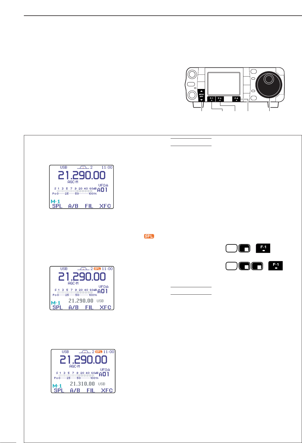
91
6FUNCTIONS FOR TRANSMIT
■Split frequency operation
qSelect VFO A and set the frequency to 21.290 MHz
(USB).
•[F-4 V/M]is available when M
-
2appears.
•[F-2 A/B]is available when M
-
1appears.
wPush [F-1 SPL]momentarily (in the M
-
1menu) to
turn the split function ON, then push [F-2 A/B](M
-
1) for 1 sec.
•The equalized transmit (VFO B) frequency and “ ”
appear on the LCD.
•The quick split function is much more convenient for
selecting the transmit frequency. See the next page for
details.
eRotate [DIAL] while pushing [F-4 XFC](M
-
1)to
set the transmit frequency to 21.310 MHz.
•[XFC] on the HM-151 can also be used.
• The transmit frequency can be monitored while pushing
[F-4 XFC].
rNow you can receive on 21.290 MHz and transmit
on 21.310 MHz.
To swap the transmit and receive frequencies, push
[F-2 A/B](M
-
1)to exchange the VFO A and VFO B.
DIRECT SHIFT FREQUENCY INPUT
The shift frequency can be entered directly.
qPush [F-INP/ENT] (HM-151).
wEnter the desired shift frequency with the digit
keys.
• 1 kHz to 1 MHz shifts can be entered.
•When you require a minus shift direction, push [50/•]
before entering the shift.
ePush [F-1 SPL](M
-
1) on the transceiver’s front
panel.
•The shift frequency is input in the sub readout and the
split function is turned ON.
[EXAMPLE]
SPLIT LOCK FUNCTION
Accidentally releasing [F-4 XFC](M
-
1)while rotating
[DIAL] changes the receive frequency. To prevent
this, use both the split lock and dial lock functions to
change the transmit frequency only. The split lock
function cancels the dial lock function while pushing
[F-4 XFC](M
-
1)during split frequency operation.
The dial lock’s effectiveness during split frequency op-
eration can be selected in the miscellaneous (others)
set mode for both receive and transmit frequencies;
or only the receive frequency. (p. 131)
CONVENIENT
F-INP
ENT
F-INP
ENT 1
1.8
3
7
.
50
To operate on 1 kHz
higher frequency:
HM-151
HM-151
Transceiver
(SPL)
(SPL)
Transceiver
To operate on 3 kHz
lower frequency:
CONVENIENT
Split frequency operation allows you to transmit and
receive in the same mode on two different frequencies.
The split frequency operation is basically performed
using 2 VFO frequencies (VFO A and VFO B) on the
main and sub readouts.
The following is an example of setting 21.290 MHz for
receiving and 21.310 MHz for transmitting.
[DIAL][MENU/GRP] [F-1] [F-2] [F-4]
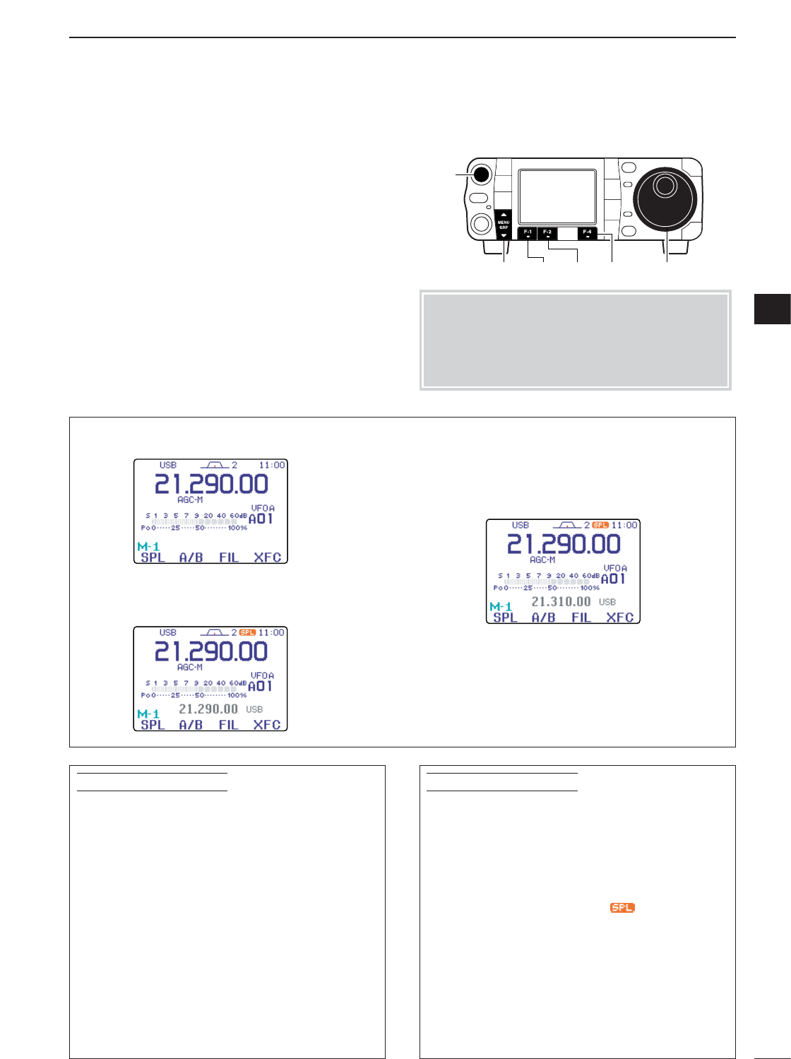
92
6
FUNCTIONS FOR TRANSMIT
6
■Quick split function
qSuppose you are operating at 21.290 MHz (USB)
in VFO A.
wPush [F-1 SPL](M
-
1) for 1 sec.
• Split frequency operation is turned ON.
•The VFO A and VFO B are equalized.
eWhile pushing [F-4 XFC](M
-
1), rotate [DIAL] to
set the frequency offset between transmit and re-
ceive.
•[XFC] on the HM-151 can also be used.
• The transmit frequency can be monitored while pushing
[F-4 XFC].
When you are searching for DX stations and you
suspect that a DX station may say “up ‘X’ kHz” for
their receive frequency:
OPERATION 1
qPush [F-1 SPL](M
-
1)for 1 sec. to standby for
split operation.
wIf the DX station’s operator says “up 10 kHz.”
•Push [F-INP/ENT],[1],[0] then [F-1 SPL](M
-
1).
• Or, rotate the tuning dial.
OPERATION 2
If the DX station’s operator says “down 5 kHz” be-
fore you enter standby for split operation:
➥Push [F-INP/ENT],[•],[5] then [F-1 SPL](M
-
1).
•The split function is turned ON and “5 kHz down” fre-
quency is entered in the sub readout.
PRACTICAL EXAMPLE
When you are working a pile-up and you want to
start split frequency operation to simplify picking out
stations:
qPush [F-1 SPL](M
-
1)momentarily and push [F-
2A/B](M
-
1) for 1 sec.
• The transmit (VFO B) frequency is equalized to the re-
ceive (VFO A) frequency and “ ” appears.
wRotate [DIAL] to set your receive frequency in the
VFO A.
eAnnounce your receive frequency.
rAfter you catch one of the calling stations’ call
signs, push and hold the PTT switch to respond.
• While pushing [F-4 XFC], you can monitor your trans-
mit frequency.
PRACTICAL EXAMPLE
When you find a DX station, an important considera-
tion is how to set the split frequency.
When you push [F-1 SPL](M-1)for 1 sec., split frequency
operation is turned ON, the undisplayed VFO is automati-
cally changed according to the plus/minus shift frequency
programmed in the miscellaneous (others) set mode
(p. 131) or equalized with the displayed VFO when 0.000
MHz (default) is programmed as the split offset frequency.
This shortens the time needed to start split frequency
operation.
Quick split operation is turned ON by default but can be
turned OFF in the miscellaneous (others) set mode (p. 131).
Menu selection (Example: M-1)
•Push [MENU/GRP] for 1 sec. once or twice to select
the menu group M.Selection from:
M
,
S
or
G
(Graphic)
•Push [MENU/GRP] momentarily one or more times to
select the menu M
-
1.Selection from:
M
-
1
,
M
-
2
or
M
-
3
[DIAL][MENU/GRP]
[AF]
[F-1] [F-2] [F-4]
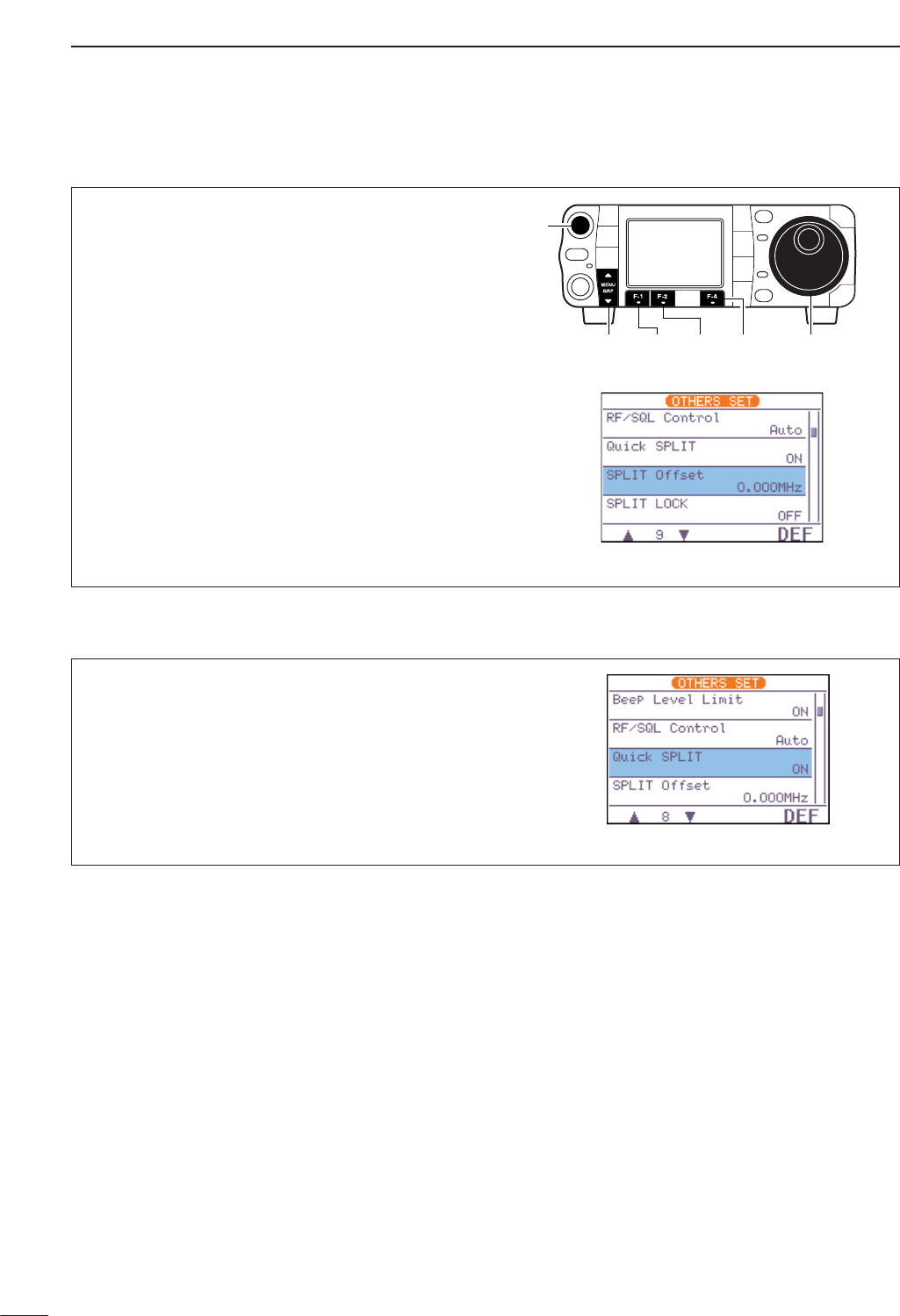
93
6FUNCTIONS FOR TRANSMIT
DQuick split setting
qEnter the miscellaneous (others) set mode as
above.
wPush [F-1 ≤]or [F-2 ≥]to select “Quick
SPLIT,” then rotate [DIAL] to select the desired
setting.
•Push [F-4 DEF]for 1 sec. to return to default setting.
ePush [Z(
MENU
/
GRP
)] twice to return the normal op-
erating mode.
DSplit offset frequency setting
By setting an often-used split frequency offset in ad-
vance, you can operate the quick split function to se-
lect split operation at the push of one key.
qPush [AF(
SET
)] momentarily to enter the set mode
menu.
wPush [F-4 OTH]to enter the miscellaneous (oth-
ers) set mode.
ePush [F-1 ≤]or [F-2 ≥]to select “SPLIT Off-
set.”
rRotate [DIAL] to set the desired split offset.
•The split offset can be selected from –9.999 MHz to
+9.999 MHz.
•Push [F-4 DEF]for 1 sec. to return to default value.
tPush [Z(
MENU
/
GRP
)] twice to return the normal op-
erating mode.
[DIAL][MENU/GRP]
[AF]
[F-1] [F-2] [F-4]
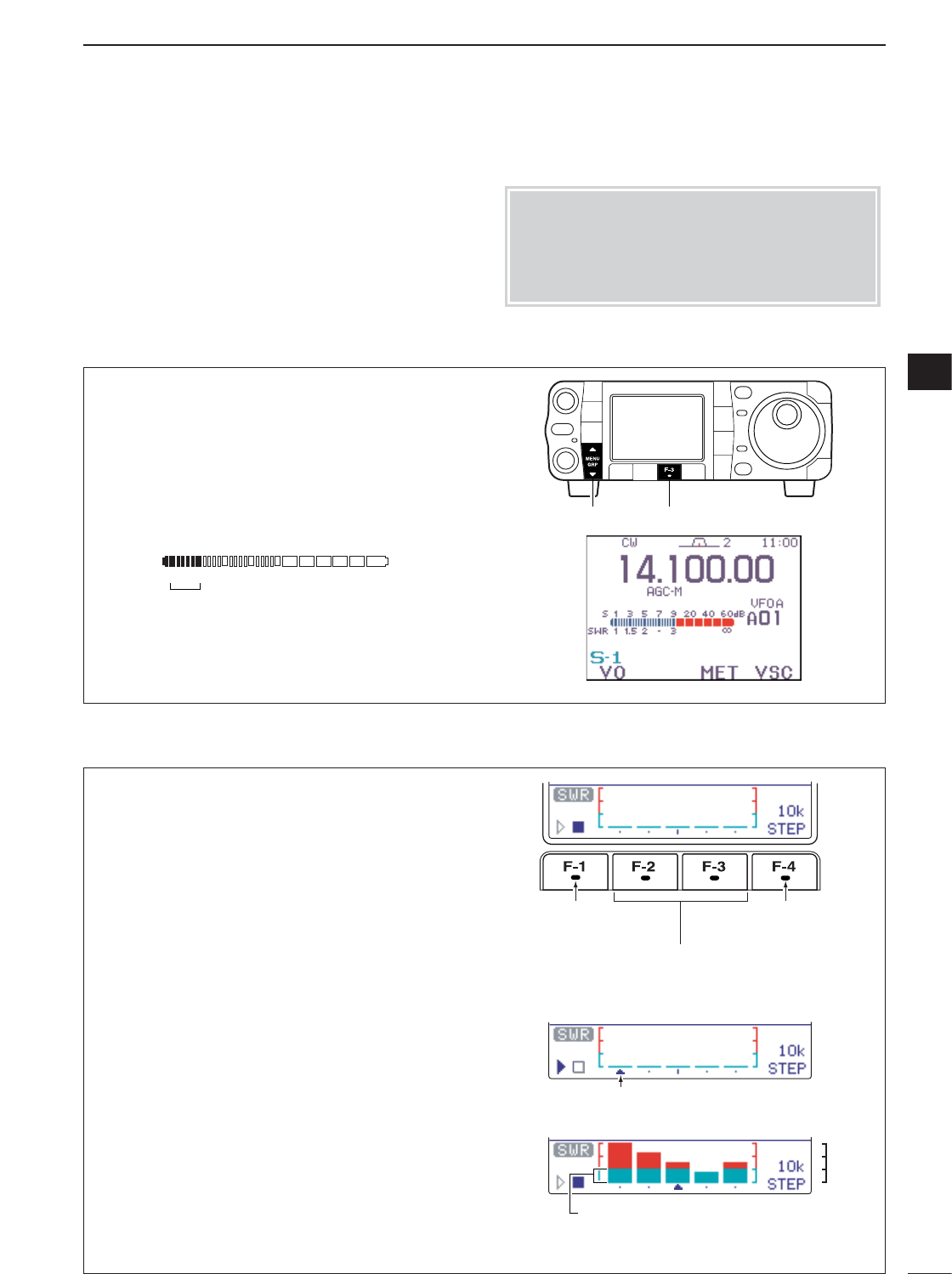
DPlot measurement
94
6
FUNCTIONS FOR TRANSMIT
6
The IC-7000 has a built-in circuit for measuring an-
tenna SWR—no external equipment or special adjust-
ments are necessary.
The IC-7000 can measure SWR in 2 ways—spot mea-
surement and plot measurement.
qSelect CW or RTTY operation with [MODE].
wConfirm that the output power is over 30 W.
eSelect the menu S
-
1.
rPush [F-3 MET]one or more times to select the
SWR meter.
tKey down or push [PTT] to transmit; then read the
actual SWR from the meter.
➠)1.5 well matched antenna
➠>1.5 check antenna or cable connection, etc.
[MENU/GRP] [F-3]
The best match is in this range.
SWR 1 1.5 2 -3'
Plot measurement allows you to measure the SWR
over an entire band.
qConfirm that the output power is over 30 W.
wSet the center frequency for the SWR to be mea-
sured.
eSelect the menu G
-
3 (SWR meter).
rPush and hold [F-4
STEP
]for 1 sec. one or more
times to select the desired measuring step from 10,
50, 100 and 500 kHz.
tPush [F-2] or [F-3] one or more times to select the
desired number of measuring steps from 3, 5, 7, 9,
11, and 13 steps.
yPush [F-1] to start the measuring.
uPush and hold [PTT] on the microphone to mea-
sure the SWR.
• Frequency marker, “∫,” appears below SWR graph.
• RTTY mode is automatically selected.
iWhen releasing [PTT], the frequency marker and
frequency indication move to the next frequency to
be measured.
oRepeat steps uand ito measure SWR over the
entire frequency range.
!0 When the measured SWR is less than 1.5:1, the
antenna is well matched with the transceiver in the
measured frequency range.
Push [F-1] to start
mesuring.
Push [F-2] or [F-3] to select number of
SWR mesuring steps.
Frequency marker appears and moves
after measurement.
Push [F-4] to Select
SWR mesuring steps.
• Measuring (after pushing [F1])
The antenna is well matched in this range
1.0 : 1
1.5 : 1
2.0 : 1
3.0 : 1
4.0 : 1
■Measuring SWR
DSpot measurement
Menu selection (Example: S-1)
•Push [MENU/GRP] for 1 sec. once or twice to select
the menu group S.Selection from:
M
,
S
or
G
(Graphic)
•Push [MENU/GRP] momentarily one or more times to
select the menu S
-
1.Selection from:
S
-
1
,
S
-
2
or
S
-
3
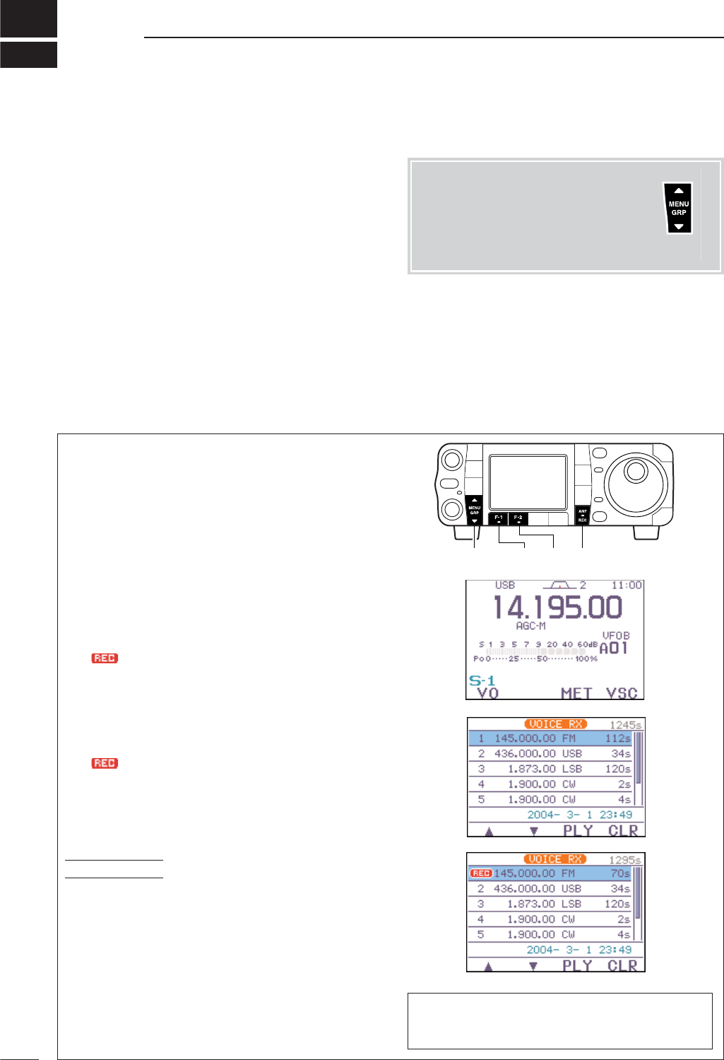
7
95
VOICE RECORDER FUNCTIONS
■Digital voice recorder
The transceiver has digital voice memories, up to 4
channels for transmit, and up to 99 channels for re-
ceive. A maximum message length of 120 sec. can be
recorded into a receive channel (total message length
for all channels of up to 1500 sec.), and a total mes-
sage length of 90 sec. can be recorded in transmit
channels.
Providing a transmission memory is very convenient
for repeated CQ and number transmissions at contest
times, as well as when making consecutive calls in
DX’pedition.
■Recording a received audio
DBasic recording
qSelect the desired frequency and mode.
wSelect S
-
1.
ePush [F-1 VO]to call up the voice recorder menu.
•If the transmit voice memory channels (T1–T4) screen
appears, push [Z(
MENU
/
GRP
)] then push [F-1 RX]to
select the receive voice memory channel.
• If the voice root menu appears, push [F-1 RX]to select
the receive voice memory menu. The voice recorder
starting menu can be changed in the miscellaneous
(others) set mode.
rPush [F-1 ≤]or [F-2 ≥]to select the new truck or
desired recorded contents to be overwritten.
tPush and hold [ANF/•REC] for 1 sec. to start
recording while receiving a signal.
• “ ” appears and the recording timer counts up.
•The operating frequency, mode and current time are
programmed as the memory names automatically.
•Previously recorded contents are cleared, if overwrit-
ten.
yPush and hold [ANF/•REC] for 1 sec. again to
stop recording.
• “ ” disappears.
•Recording is automatically terminated after 120 sec. or
when a total of the recorded time becomes 1500 sec.
uPush [Z(
MENU
/
GRP
)] twice to exit the voice recoder
mode.
MIC Memo FUNCTION
While recordig a received audio, speak into micro-
phone (without pushing [PTT]) to record your com-
ment, impression or some information with recorded
audio.
This function can be activate in the voice set mode.
(p. 101) The voice recoder stores the received audio in 15
sec. blocks. Thus the total recording time is re-
duced by 15 sec. each time recording is stopped.
[MENU/GRP] [F-1] [F-2] [ANF/•REC]
CONVENIENT
Menu group selection
Push [MENU/GRP] for 1 sec.
Selection from:
M
,
S
or
G
(Graphic)
Menu selection (Example: S)
Push [MENU/GRP] momentarily.
Selection from:
S
-
1
,
S
-
2
or
S
-
3
Either
Y or Z
Either
Y or Z
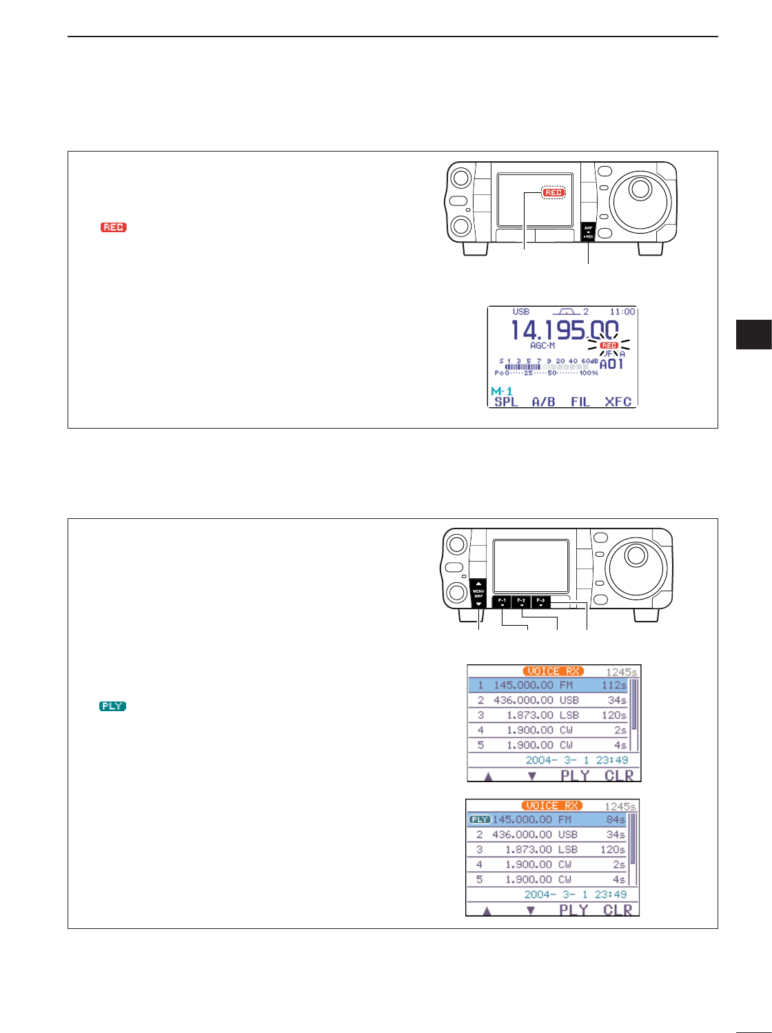
96
7
VOICE RECORDER FUNCTIONS
7
To record the receiving signal contents immediately,
one-touch voice recording is available.
qPush and hold [ANF/•REC] for 1 sec. while re-
ceiving a signal to start recording.
• “ ” blinks.
• Records audio into the new track.
wPush and hold [ANF/•REC] for 1 sec. again to
stop recording.
•Recording is automatically terminated after 120 sec. or
when a total of the recorded time becomes 1500 sec.
[ANF/•REC]
Blinks
qSelect S
-
1.
wPush [F-1 VO]to call up the voice recorder menu.
•If the transmit voice memory channels (T1–T4) screen
appears, push [Z(
MENU
/
GRP
)] then push [F-1 RX]to
select the receive voice memory channel.
• If the voice root menu appears, push [F-1 RX]to select
the receive voice memory menu. The voice recorder
starting menu can be changed in the miscellaneous
(others) set mode.
ePush [F-1 ≤]or [F-2 ≥]to select the desired
recorded contents, then push [F-3 PLY]to play-
back.
• “ ” appears.
rPush [F-3 PLY]again to stop playback, if desired.
•Playback is terminated automatically when all of the
recorded contents in the channel are played.
tPush [Z(
MENU
/
GRP
)] twice to exit the voice recoder
mode.
[MENU/GRP] [F-2] [F-3][F-1]
■Playing the recorded contents
DOne-touch voice recording
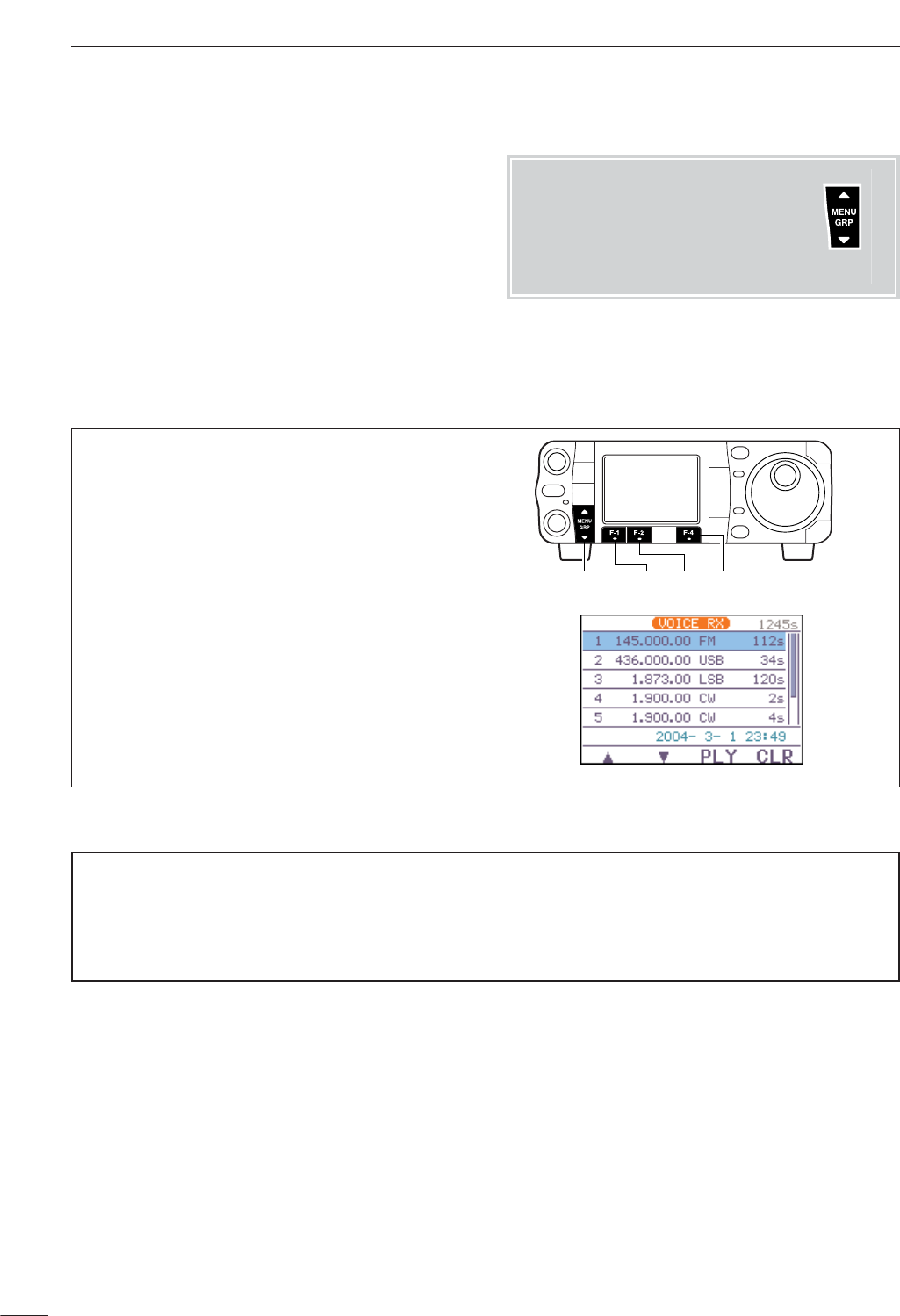
97
7VOICE RECORDER FUNCTIONS
The recorded contents can be erased independently
by channel.
qSelect S
-
1.
wPush [F-1 VO]to call up the voice recorder menu.
•If the transmit voice memory channels (T1–T4) screen
appears, push [Z(
MENU
/
GRP
)] then push [F-1 RX]to
select the receive voice memory channel.
• If the voice root menu appears, push [F-1 RX]to select
the receive voice memory menu. The voice recorder
starting menu can be changed in the miscellaneous
(others) set mode.
ePush [F-1 ≤]or [F-2 ≥]to select the desired
recorded contents to be erased, then push and
hold [F-4 CLR]for 1 sec. to erase the contents.
rPush [Z(
MENU
/
GRP
)] twice to exit the voice recoder
mode.
[MENU/GRP] [F-2] [F-4][F-1]
■Erasing the recorded contents
Menu group selection
Push [MENU/GRP] for 1 sec.
Selection from:
M
,
S
or
G
(Graphic)
Menu selection (Example: S)
Push [MENU/GRP] momentarily.
Selection from:
S
-
1
,
S
-
2
or
S
-
3
Either
Y or Z
Either
Y or Z
Erasing a long message takes a little time, and a maximum message length (120 sec./channel) takes over 1
sec.
When resetting the CPU, the transceiver clears all of the voice memory area (1500 sec.), and it takes almost 30
sec. In these cases, you can use the record function, but you cannot playback the recorded contents during the
clearing process unitil it is completed.
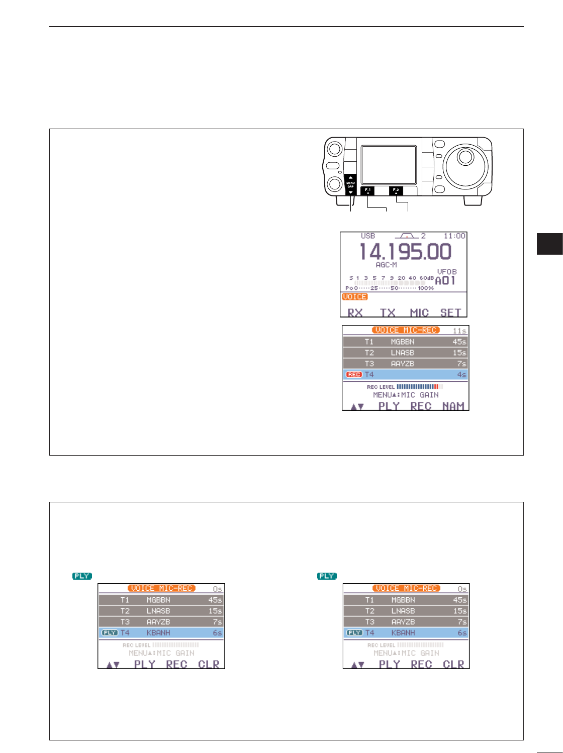
98
7
VOICE RECORDER FUNCTIONS
To transmit a message using a voice recorder, record
the desired message in advance as described below.
qSelect S
-
1.
wPush [F-1 VO]then [Z(
MENU
/
GRP
)] to select the
voice root menu.
•If the voice root menu appears, skip the pushing
[Z(
MENU
/
GRP
)]. The voice starting menu can be
changed in the miscellaneous (others) set mode.
ePush [F-3 MIC]to select the voice memory
recording mode.
rPush [Y(
MENU
/
GRP
)] then rotate [DIAL] to adjust
the mic gain control so that the “REC LEVEL” in-
dicator reads within maximum.
•Speak into the microphone without pushing [PTT].
•Push [F-4 DEF]to select the default mic gain.
•Push [Z(
MENU
/
GRP
)] to exit the mic gain adjustment
condition.
tPush [F-1 ≤≥]to select the desired memory chan-
nel, then push and hold [F-3 REC]for 1 sec. to
start recording.
•Speak into the microphone without pushing [PTT].
• Previously recorded contents are cleared.
yPush [F-3 REC]again to stop recording.
•Recording is automatically terminated when the total
time of recorded messages, T1–T4, becomes 90 sec.
uPush [Z(
MENU
/
GRP
)] twice to exit the voice mem-
ory screen.
[MENU/GRP] [F-3][F-1]
■Recording a message for transmit
7
DRecording
DConfirming/Erasing the recorded message
• Playing the recorded contents
qCall up the voice memory recording mode as de-
scribed in steps qto eas shown above.
wPush [F-1 ≤≥]to select the desired memory chan-
nel, then push [F-2 PLY]to start playback.
• “ ” appears.
ePush [F-2 PLY]again to stop playback, if desired.
rPush [Z(
MENU
/
GRP
)] twice to exit the voice mem-
ory mode
•Erasing the recoded contents
qCall up the voice memory recording mode as de-
scribed in steps qto eas shown above.
wPush [F-1 ≤≥]to select the desired memory chan-
nel to be erased, push [F-2 PLY]to start playback.
• “ ” appears.
ePush and hold [F-4 CLR]for 1 sec. to erase the
contents.
rPush [Z(
MENU
/
GRP
)] twice to exit the voice mem-
ory mode.
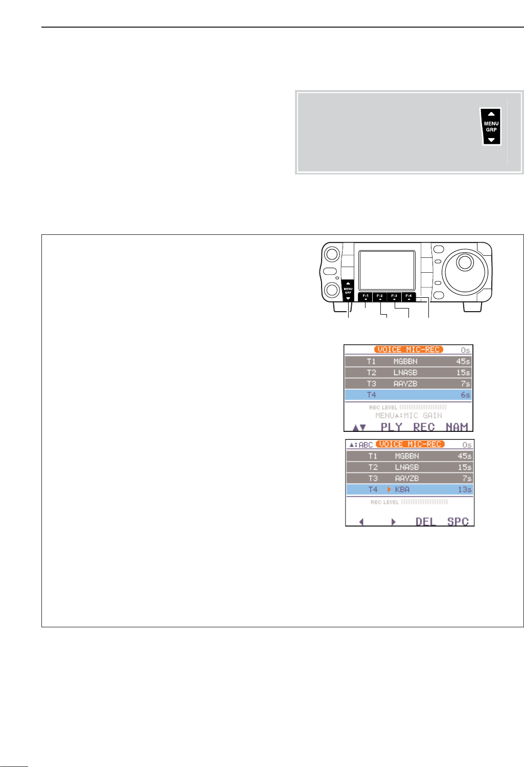
99
7VOICE RECORDER FUNCTIONS
Memory channels can be tagged with alphanumeric
names of up to 5 characters each.
Capital letters, small letters, numerals, some symbols
(! # $ % & ¥ ? " ' ` ^ + – ✱/.,: ; = < > ( ) [ ] { } | _ _@)
and spaces can be used. (See the step tbelow.)
qRecord a message as described at previous page.
wCall up the voice memory recording mode as de-
scribed in steps qto e(see the instructions for
recording at previous page).
ePush [F-1 ≤]or [F-2 ≥]to select the desired voice
memory.
rPush [F-4 NAM]to enter memory name edit condi-
tion.
• A cursor appears and blinks.
•Memory channel names of no-recorded channels
cannnot be selected.
tPush [Y(
MENU
/
GRP
)] several times to select the de-
sired character group.
•[ABC],[abc],[123] or [etc] indicates the capital letters,
small letters, numerals or symbols, respectively
yInput the desired character by rotating [DIAL].
•Push [F-1 Å]or [F-2 Ç]for cursor movement.
•Push [F-3 DEL]to delete the selected character.
•Push [F-4 SPC]to input a space.
•Pushing the HM-151’s keypad, [0]–[9], can also enter
numerals.
uPush [Z(
MENU
/
GRP
)] to input and set the name.
• The cursor disappears.
iRepeat steps eto yto program another voice
memory’s name, if desired.
oPush [Z(
MENU
/
GRP
)] twice to exit the voice mem-
ory screen.
[MENU/GRP] [F-2] [F-3] [F-4]
[F-1]
■Programming a memory name for transmit
Menu group selection
Push [MENU/GRP] for 1 sec.
Selection from:
M
,
S
or
G
(Graphic)
Menu selection (Example: S)
Push [MENU/GRP] momentarily.
Selection from:
S
-
1
,
S
-
2
or
S
-
3
Either
Y or Z
Either
Y or Z
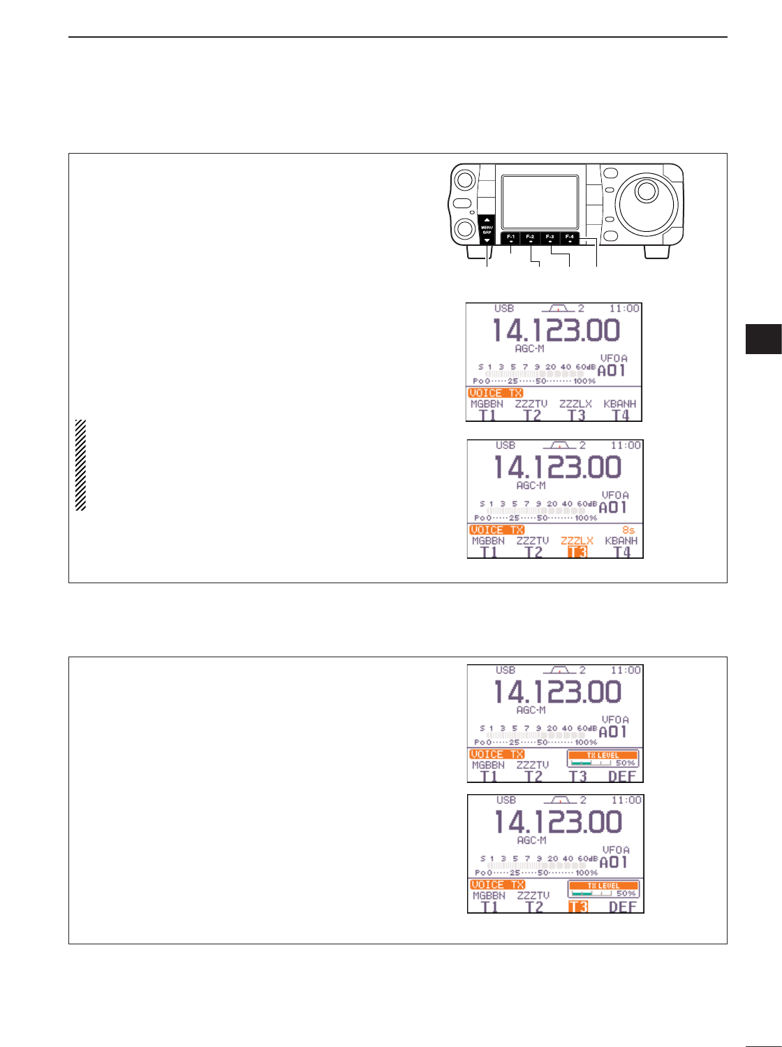
100
7
VOICE RECORDER FUNCTIONS
7
qSelect S
-
1.
wPush [F-1 VO]to call up the voice recorder menu.
•If the receive voice memory channels screen appears,
push [Z(
MENU
/
GRP
)] then push [F-2 TX]to select the
transmit voice memory channel.
• If the voice root menu appears, push [F-2 TX]to select
the transmit voice memory menu. The voice recorder
starting menu can be changed in the miscellaneous
(others) set mode.
ePush [F-1 T1]—[F-4 T4]to transmit the con-
tents.
•“T1”– “T4” are highlighted while transmitting.
rPush the selected memory channel key, [F-1 T1]
—[F-4 T4], again to stop, if desired.
tPush [Z(
MENU
/
GRP
)] twice to exit the voice mem-
ory screen.
For your information
When an external keypad is connected to the pin 3
and pin 7 of the [MIC] connecter, the recorded
message, T1–T4, can be transmitted without open-
ing the voice recorder set screen.
See page 137 for details.
[MENU/GRP] [F-2] [F-3] [F-4]
[F-1]
■Sending a recorded message
qCall up the voice memory recording mode as de-
scribed in steps qto was above.
wPush [Y(
MENU
/
GRP
)] to select the voice memory
transmit level set mode.
ePush the desired memory channel key, [F-1 T1]–
[F-3 T3], momentarily to transmit the contents.
rRotate [DIAL] to adjust the transmit voice level.
•Push [F-4 DEF]to select the default condition.
tPush [Z(
MENU
/
GRP
)] to return to the voice recorder
screen.
DTransmit level setting
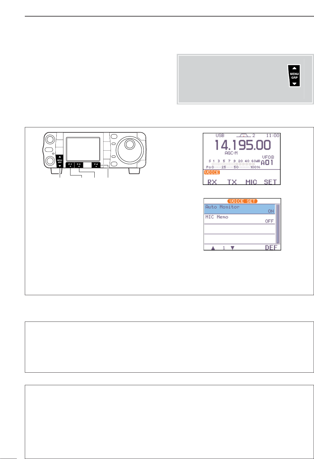
101
7VOICE RECORDER FUNCTIONS
qSelect S
-
1.
wPush [F-1 VO]then [Z(
MENU
/
GRP
)] to select the
voice root menu.
•If the voice root menu appears, skip the pushing
[Z(
MENU
/
GRP
)]. The voice starting menu can be
changed in the miscellaneous (others) set mode.
ePush [F-4 SET]to enter the voice recorder set
mode.
rPush [F-1 ≤]or [F-2 ≥]to select the desired item,
then rotate [DIAL] to set the selected function ON
and OFF.
•Push [F-4 DEF]for 1 sec. to select the default condi-
tion.
tPush [Z(
MENU
/
GRP
)] to return to the voice root
menu.
[MENU/GRP] [F-2] [F-4][F-1]
■Voice set mode
DVoice set mode
1. Auto Monitor
This item selects the auto monitor function ON and
OFF. When this function is ON,
the monitor function is
automatically turned ON while transmitting a voice
memory message.
•Push [F-4 DEF]for 1 sec. to return to default setting.
ON
Automatic monitor function
is ON. (default)
OFF
Automatic monitor function
is OFF.
2. MIC Memo
This item selects the mic memo function ON and OFF.
When this function is ON,
and you speak into the mi-
crophone (without pushing [PTT]), your voice are
mixed with the received audio and recorded.
This function is convienient when you want to record
some information or comment while recording the re-
ceived audio.
•Push [F-4 DEF]for 1 sec. to return to default setting.
ON
MIC memo function is ON.
OFF
MIC memo function is OFF.
(default)
Menu group selection
Push [MENU/GRP] for 1 sec.
Selection from:
M
,
S
or
G
(Graphic)
Menu selection (Example: S)
Push [MENU/GRP] momentarily.
Selection from:
S
-
1
,
S
-
2
or
S
-
3
Either
Y or Z
Either
Y or Z
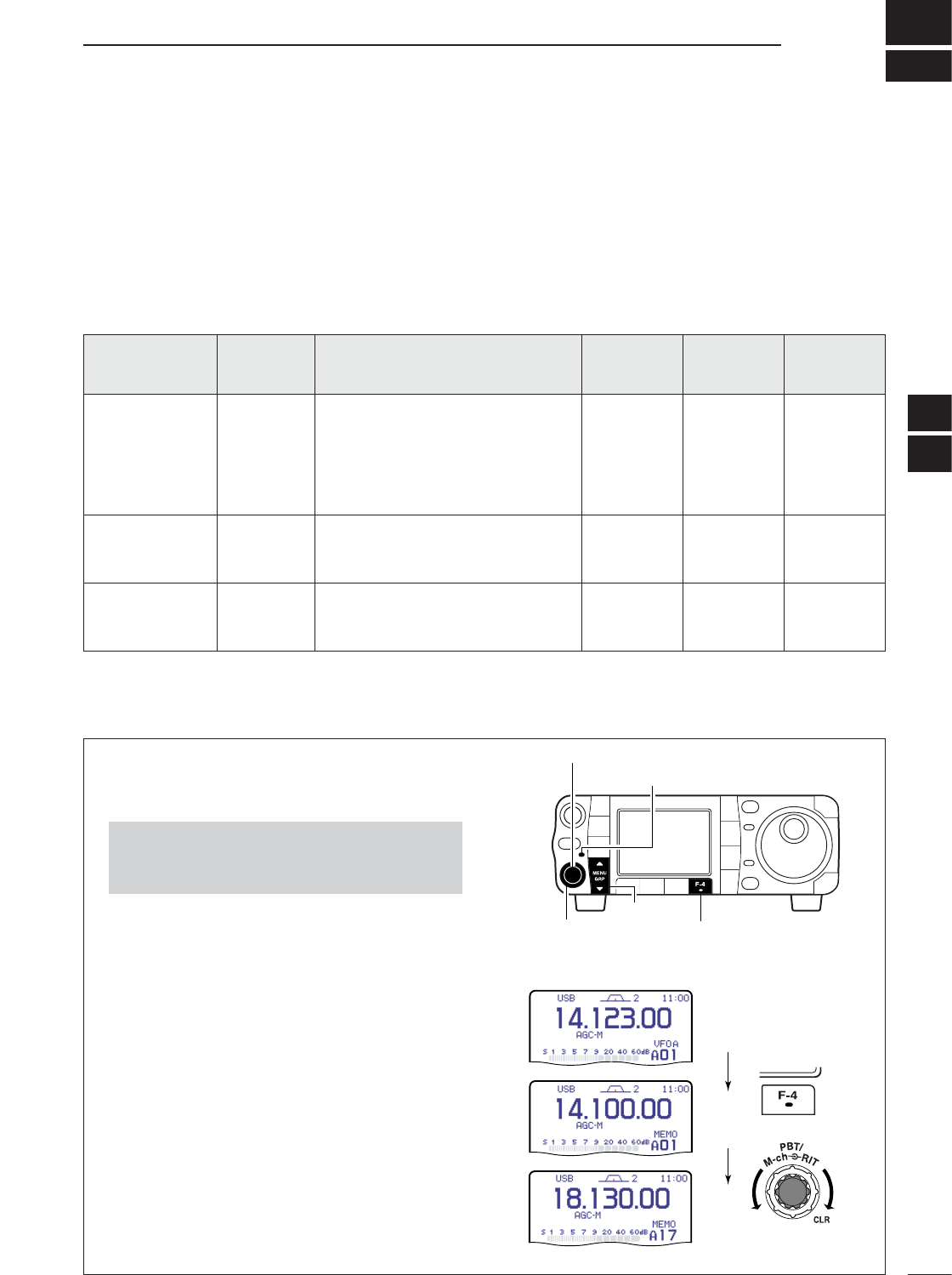
■Memory channel selection
8
102
MEMORY OPERATION
The transceiver has 501 memory channels includes 6
scan edge channels (3 pairs), and 2 call channels. In
addition, a total of 5 memory banks (99 memory chan-
nel each), A to E, are available for usage by group, etc.
Memory mode is very useful for quickly changing to
often-used frequencies.
All 503 memory/call channels are tuneable which
means the programmed frequency can be tuned tem-
porarily with [DIAL], etc., in memory mode.
MEMORY
CHANNEL
MEMORY
CHANNEL
NUMBER
CAPABILITY TRANSFER
TO VFO
OVER-
WRITING CLEAR
Regular
(split memory)
1–99
(in each
banks)
Independent transmit and receive
frequencies and one mode in each
memory channel.
In addition, tone frequencies can
also be stored for repeater use.
Yes Yes Yes
Scan edges 1A–3B
(common)
One frequency and one mode in
each memory channel as scan
edges for programmed scan.
Yes Yes No
Call channels
(split memory)
C1, C2
(common)
Same as regular channels, but 144
MHz (C1), 430 MHz (C2) band can
be programmed.
Yes Yes No
■Memory channels
qPush [PBT/M-ch/RIT] momentarily to select the M-
ch/RIT function, if the twin PBT is selected.
•[PBT/M-ch/RIT] indicator (Green) goes out.
wSelect the menu M
-
2.
ePush [F-4 V/M]to select memory mode.
rRotate [M-ch] (inner) control to select the desired
memory channel.
•All memory channels including blank channels can be
selected.
•Rotating [RIT] (outer) control changes the bank.
•[Y]/[Z]on the microphone also change the channels.
tTo return to VFO mode, push [F-4 V/M]again.
[EXAMPLE]: Selecting memory channel 17.
V/M
[MENU/GRP]
[F-4][RIT] (outer) control
[PBT/M-ch/RIT] indicator
[PBT/M-ch/RIT] switch/[M-ch] (inner) control
•Push and hold [MENU/GRP] for 1 sec. once or twice
to select the menu group M.
•Push [MENU/GRP] momentarily one or more times to
select the menu M
-
2.
7
8
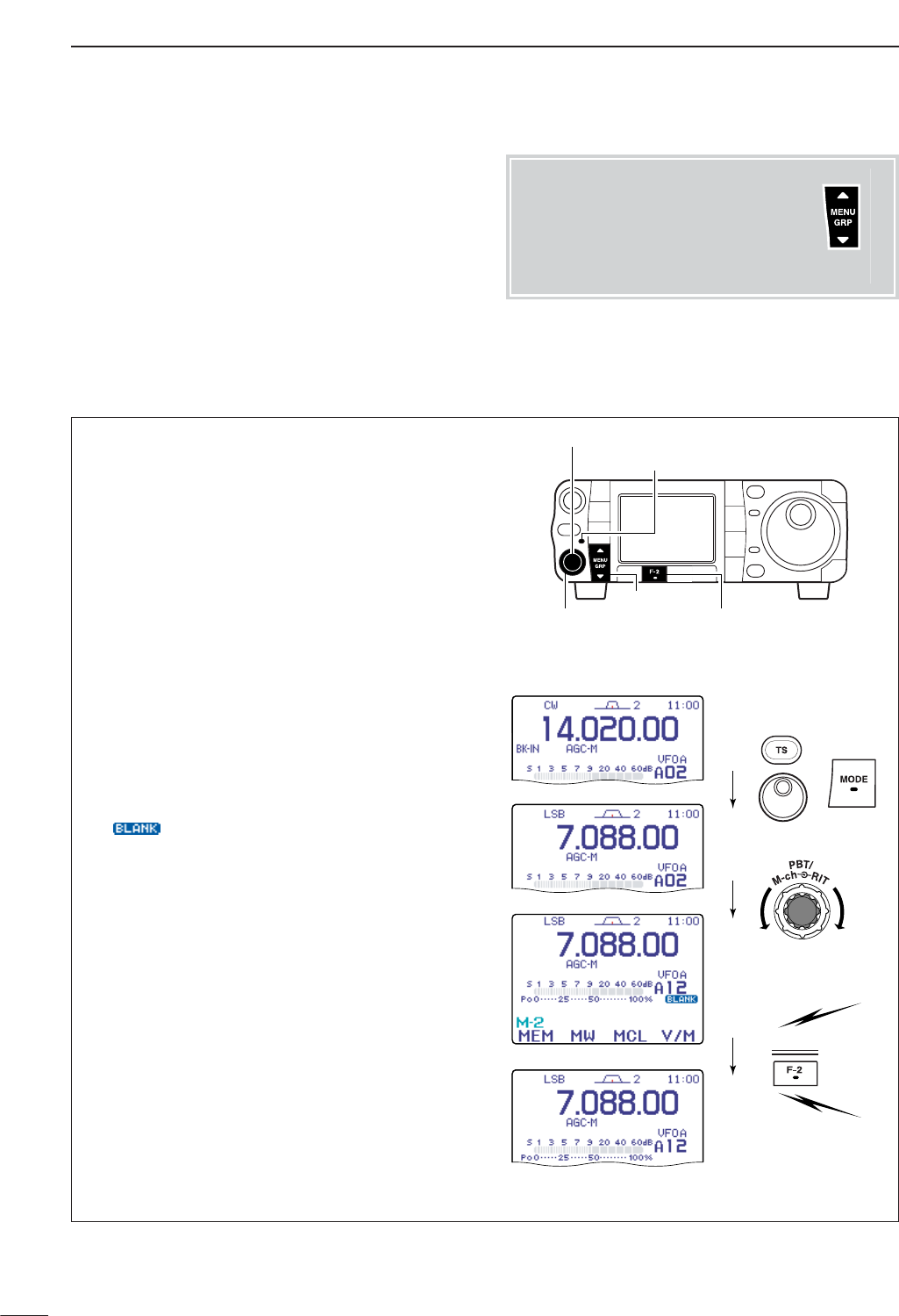
103
8MEMORY OPERATION
qPush [PBT/M-ch/RIT] momentarily to select the M-
ch/RIT function, if the twin PBT is selected.
•[PBT/M-ch/RIT] indicator (Green) goes out.
wSet the desired frequency and operating mode in
VFO mode.
•If you want to program the split frequency function, pro-
gram both receive and transmit frequencies into VFO
A and B, then turn ON the split function. (p. 91)
•If you want to program a repeater function, set a tone
frequency (p. 60) in addition to the receive/transmit fre-
quencies.
eSelect the menu M
-
2.
rPush [F-1 MEM]to display the memory channel
contents.
•Memory channel contents appear above the multi-func-
tion key indicator.
•Push [F-1 LST]to display the memory channel list.
This is convenient for selecting the desired channel.
Push [Z(
MENU
/
GRP
)] to exit the memory channel list.
tRotate [M-ch] to select the desired memory chan-
nel.
•“ ” and “---,---,--” appear if the selected memory
channel is a blank channel (and does not have con-
tents).
•Rotating [RIT] (outer) control changes the bank.
yPush [F-2 MW]for 1 sec. to program the displayed
frequency and operating mode into the selected
memory channel.
To check the programmed contents, push [F-4 V/M]
to select memory mode.
[EXAMPLE]: Programming 7.088 MHz/LSB into ch 12.
Push for
1 sec.
MW
[F-2]
[PBT/M-ch/RIT] indicator
[PBT/M-ch/RIT] switch/[M-ch] (inner) control
[MENU/GRP]
[RIT] (outer) control
■Memory programming
DProgramming in VFO mode
Memory channel programming can be performed ei-
ther in VFO mode or in memory mode.
Menu group selection
Push [MENU/GRP] for 1 sec.
Selection from:
M
,
S
or
G
(Graphic)
Menu selection (Example: M)
Push [MENU/GRP] momentarily.
Selection from:
M
-
1
,
M
-
2
or
M
-
3
Either
Y or Z
Either
Y or Z
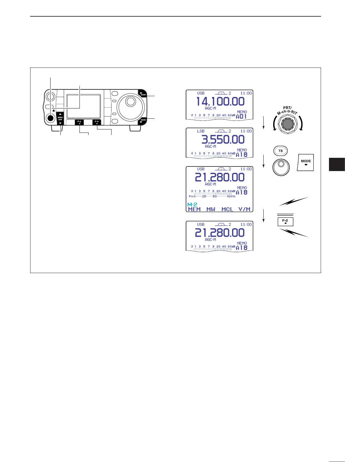
104
8
MEMORY OPERATION
8
qPush [PBT/M-ch/RIT] momentarily to select the M-
ch/RIT function, if the twin PBT is selected.
•[PBT/M-ch/RIT] indicator (Green) goes out.
wSelect the menu M
-
2.
ePush [F-4 V/M]to select memory mode, then se-
lect the desired memory channel with [M-ch].
•Memory channel contents appear instead of the VFO’s
frequency readout.
rSet the desired frequency and operating mode.
•To program a blank channel, push [Y(
BAND
)] or
[Z(
BAND
)] to select the desired band or use direct fre-
quency entry with the keypad (HM-151).
tPush [F-2 MW]for 1 sec. to program the displayed
frequency and operating mode into the memory
channel.
[EXAMPLE]:
Programming 21.280 MHz/USB into
ch 18.
Push for
1 sec.
MW
[MENU/GRP]
[PBT/M-ch/RIT] indicator
[PBT/M-ch/RIT] switch/[M-ch] (inner) control
[F-2] [F-4]
[Y]
[Z]
DProgramming in memory mode
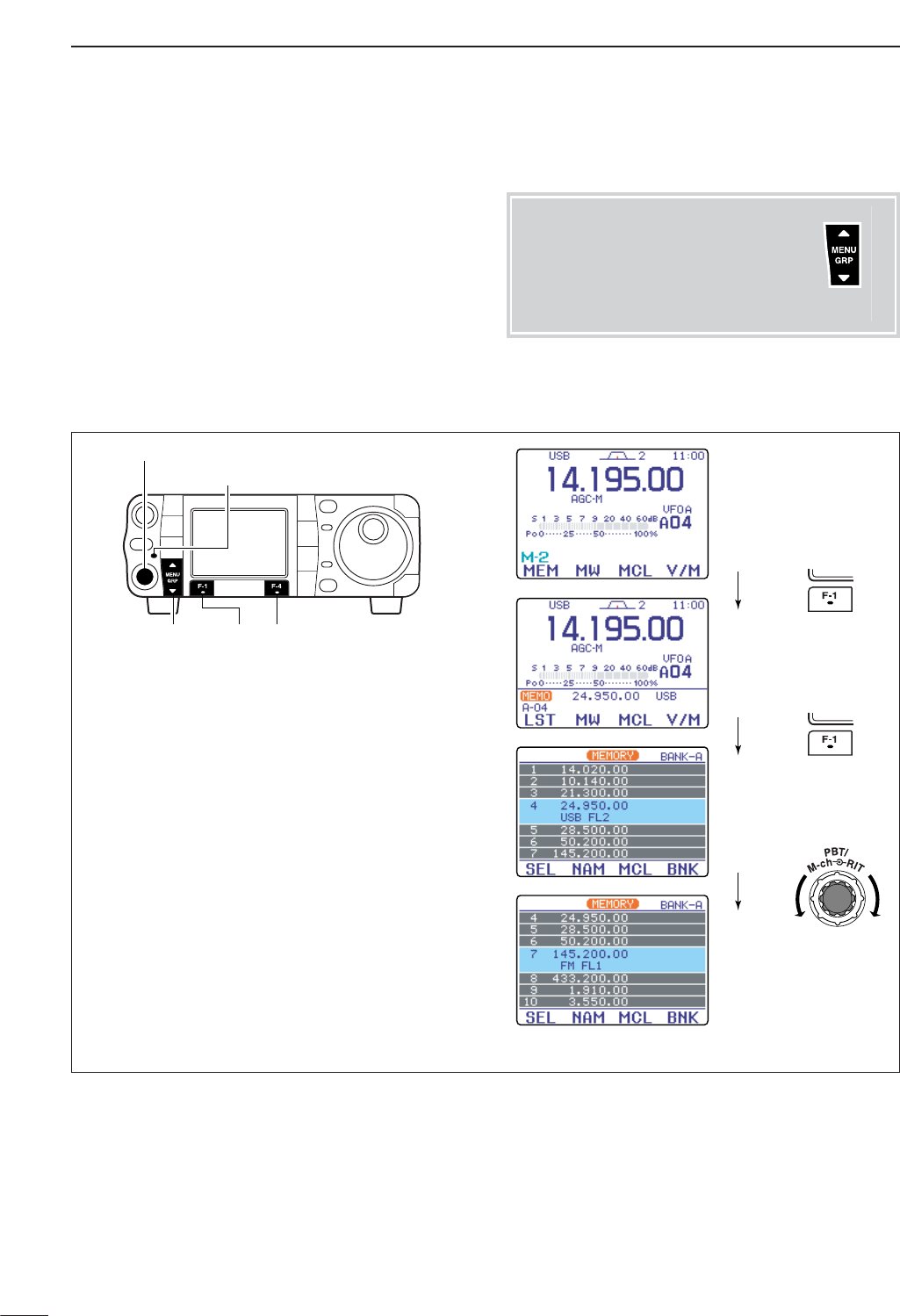
105
8MEMORY OPERATION
qSelect the menu M
-
2.
wPush [F-4 V/M]to select memory mode.
ePush [F-1] (MEM,LST) twice to enter the memory
channel list.
rPush [PBT/M-ch/RIT] momentarily to select the M-
ch/RIT function, if the twin PBT is selected.
•[PBT/M-ch/RIT] indicator (Green) goes out.
tRotate [M-ch] (inner) control to select the desired
memory channel.
•All memory channels including blank channels can be
selected.
•[Y]/[Z]on the microphone also changes the channels.
yTo exit the memory channel list, push
[Z(
MENU
/
GRP
)] twice.
Push
Push
Rotate
MEM
LST
[MENU/GRP] [F-1]
[PBT/M-ch/RIT] indicator
[PBT/M-ch/RIT] switch/[M-ch] (inner) control
[F-4]
■Memory channel list
DSelecting a memory channel using the memory channel list
The memory channel list simultaneously shows 7
memory channels and their programmed contents.
You can select a desired memory channel from the
memory channel list.
Menu group selection
Push [MENU/GRP] for 1 sec.
Selection from:
M
,
S
or
G
(Graphic)
Menu selection (Example: M)
Push [MENU/GRP] momentarily.
Selection from:
M
-
1
,
M
-
2
or
M
-
3
Either
Y or Z
Either
Y or Z
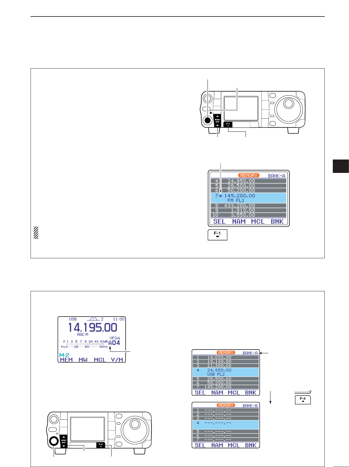
106
8
MEMORY OPERATION
8
Select memory channels are used for select memory
scan. Select memory scan repeatedly scans the se-
lect memory channels only. This is useful to speed up
the memory scan interval. Of course, select memory
channels are also scanned during normal memory
scan.
qSelect the memory channel list as described at left.
wPush [PBT/M-ch/RIT] momentarily to select the M-
ch/RIT function, if the twin PBT is selected.
•[PBT/M-ch/RIT] indicator (Green) goes out.
eRotate [M-ch] (inner) control to select the desired
memory channel.
•All memory channels including blank channels can be
selected.
•[Y]/[Z]on the microphone also changes the channels.
rPush [F-1 SEL]to set the memory channel as a
select memory or not.
tRepeat steps eto rto program another memory
channel as a select memory channel, if desired.
yPush [Z(
MENU
/
GRP
)] twice to exit the memory
channel list.
Setting select memory channels is also possible in
the memory scan indication. (p. 115)
“ß” appears for select memory channel.
Push [F-1 SEL]
[MENU/GRP] [F-1]
[PBT/M-ch/RIT] indicator
[PBT/M-ch/RIT] switch/[M-ch] (inner) control
DSetting a memory channel as a select memory
The IC-7000 has a total of 5 memory banks (99 mem-
ory channel each), A to E, are available for usage by
group, etc.
qSelect the memory channel as described at p. 102.
wPush [PBT/M-ch/RIT] momentarily to select the M-
ch/RIT function, if the twin PBT is selected.
•[PBT/M-ch/RIT] indicator (Green) goes out.
eRotate [RIT] (outer) control to select the desired
memory bank.
•Memory channel list indication
qSelect the memory channel list as described at left.
wPush [F-4 BNK]several times to select the desired
memory bank.
•Rotating [RIT] (outer) control also changes the bank.
ePush [Z(
MENU
/
GRP
)] twice to exit the memory
channel list.
Push
Bank indication
BNK
[F-4]
[MENU/GRP]
[RIT] (outer) control
Bank indication
DSelecting a memory bank
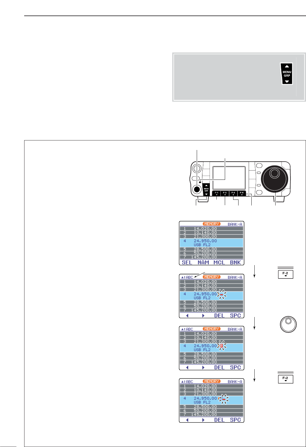
107
8MEMORY OPERATION
DMemory names
All memory channels (including scan edges) can be
tagged with alphanumeric names of up to 9 charac-
ters each.
Capital letters, small letters, numerals, some symbols
(! # $ % & ¥ ? " ’ ` ^ + – ✱/ . , : ; = < > ( ) [ ] { } | _ _@)
and spaces can be used.
• Editing (programming) memory names
qSelect the menu M
-
2.
wPush [F-4 V/M]to select memory mode.
ePush [F-1] (MEM,LST) twice to enter the memory
channel list.
rPush [PBT/M-ch/RIT] momentarily to select the M-
ch/RIT function, if the twin PBT is selected.
•[PBT/M-ch/RIT] indicator (Green) goes out.
tRotate [M-ch] (inner) control to select the desired
memory channel.
•All memory channels including blank channels can be
selected.
•[Y]/[Z]on the microphone also changes the channels.
yPush [F-2 NAM]to edit memory channel name.
• A cursor appears and blinks.
•Memory channel names of blank channels cannot be
edited.
uPush [Y(
MENU
/
GRP
)] several times to select the de-
sired character group.
•[ABC],[abc],[123] or [etc] indicates the capital letters,
small letters, numerals or symbols, respectively
iInput the desired character by rotating [DIAL].
•Push [F-1 Å]or [F-2 Ç]for cursor movement.
•Push [F-3 DEL]to delete the selected character.
•Push [F-4 SPC]to input a space.
•Pushing the HM-151’s keypad, [0]–[9], can also enter
numerals.
oPush [Z(
MENU
/
GRP
)] to input and set the name.
• The cursor disappears.
!0 Repeat steps tto oto program another memory
channel’s name, if desired.
!1 Push [Z(
MENU
/
GRP
)] twice to exit the memory
channel list.
Push
Rotate
NAM
Push
Ç
Selected character
[PBT/M-ch/RIT] indicator
[PBT/M-ch/RIT] switch/[M-ch] (inner) control
[DIAL][MENU/GRP]
[F-1]
[F-2] [F-3] [F-4]
Menu group selection
Push [MENU/GRP] for 1 sec.
Selection from:
M
,
S
or
G
(Graphic)
Menu selection (Example: M)
Push [MENU/GRP] momentarily.
Selection from:
M
-
1
,
M
-
2
or
M
-
3
Either
Y or Z
Either
Y or Z
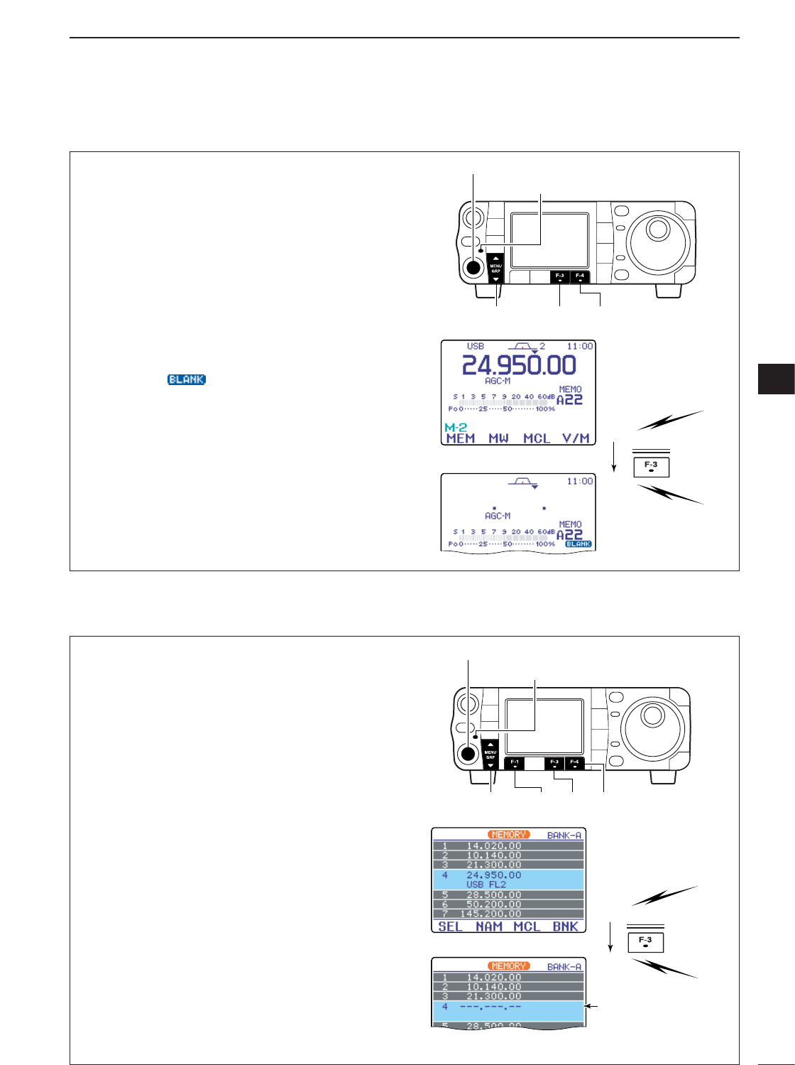
108
8
MEMORY OPERATION
8
qSelect the menu M
-
2.
wPush [F-4 V/M]to select memory mode.
ePush [F-1] (MEM,LST) twice to enter the memory
channel list.
rPush [PBT/M-ch/RIT] momentarily to select the M-
ch/RIT function, if the twin PBT is selected.
•[PBT/M-ch/RIT] indicator (Green) goes out.
tRotate [M-ch] to select the memory channel to be
cleared (blanked).
yPush [F-3 MCL]for 1 sec. to clear the contents.
uPush [Z(
MENU
/
GRP
)] twice to exit the memory
channel list.
MCL Push for
1 sec.
Programmed frequency
and operating mode
disappear.
[MENU/GRP]
[PBT/M-ch/RIT] indicator
[PBT/M-ch/RIT] switch/[M-ch] (inner) control
[F-1] [F-3] [F-4]
DMemory clearing using the memory channel list
Any unnecessary memory channels can be cleared.
The cleared memory channels become blank chan-
nels.
qSelect the menu M
-
2.
wPush [F-4 V/M]momentarily to select the memory
mode.
ePush [PBT/M-ch/RIT] momentarily to select the M-
ch/RIT function, if the twin PBT is selected.
•[PBT/M-ch/RIT] indicator (Green) goes out.
rRotate [M-ch] to select the memory channel to be
cleared.
tPush [F-3 MCL]for 1 sec. to clear the contents.
•The programmed frequency and operating mode dis-
appear and “”appears.
yTo return to VFO mode, push [F-4 V/M]again.
Push for
1 sec.
MCL
[MENU/GRP] [F-3]
[PBT/M-ch/RIT] indicator
[PBT/M-ch/RIT] switch/[M-ch] (inner) control
[F-4]
■Memory clearing
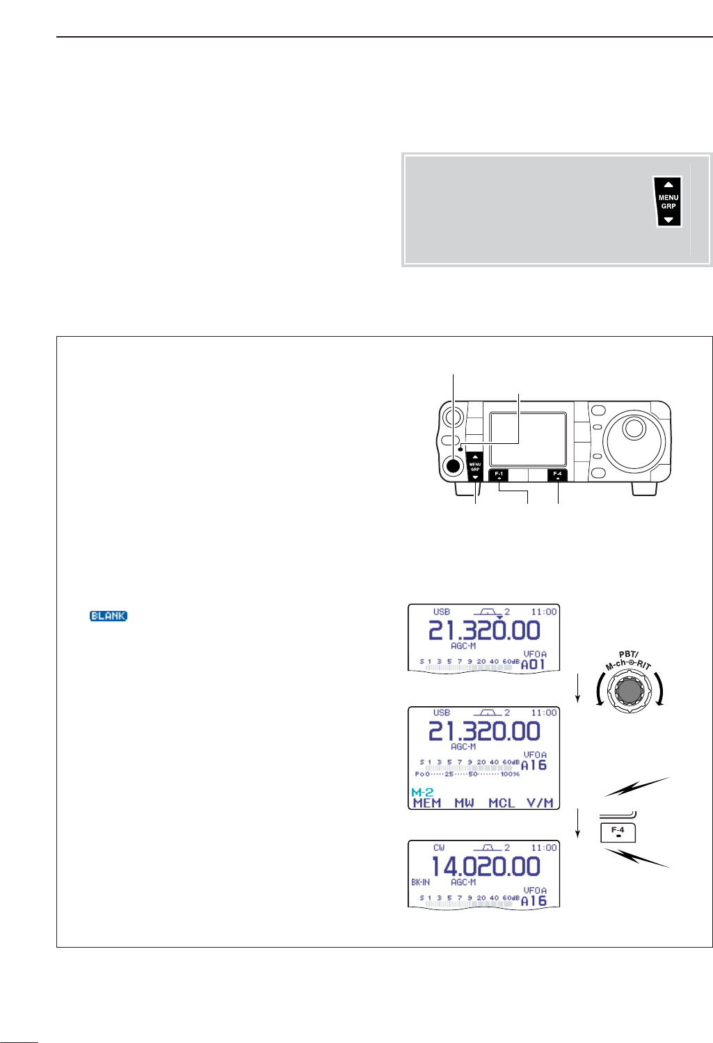
109
8MEMORY OPERATION
■Frequency transferring
This is useful for transferring programmed contents to
VFO.
qSelect the menu M
-
2.
•Push and hold [MENU/GRP] for 1 sec. once or twice
to select the menu group M.
•Push [MENU/GRP] momentarily one or more times to
select the menu M
-
2.
wPush [F-4 V/M]momentarily to select the VFO
mode.
ePush [F-1 MEM]to display the memory channel
contents.
•Memory channel contents appear above the multi-func-
tion key indicator.
rPush [PBT/M-ch/RIT] momentarily to select the M-
ch/RIT function, if the twin PBT is selected.
•[PBT/M-ch/RIT] indicator (Green) goes out.
tSelect a memory channel with [M-ch].
•“ ” appears if the selected memory channel is a
blank channel (and does not have contents). In this
case transferring is not possible.
yPush [F-4 V/M]for 1 sec. to transfer the frequency
and operating mode.
•Transferred frequency and operating mode appear in
the display.
[EXAMPLE]: Transferring contents of memory 16.
Operating frequency
Contents of memory 16
Push for
1 sec.
V/M
: 21.320 MHz/USB (VFO)
: 14.020 MHz/CW
[MENU/GRP] [F-1]
[PBT/M-ch/RIT] indicator
[PBT/M-ch/RIT] switch/[M-ch] (inner) control
[F-4]
DTransferring in VFO mode
The frequency and operating mode in a memory chan-
nel can be transferred to the VFO.
Frequency transferring can be performed in either VFO
mode or memory mode.
Menu group selection
Push [MENU/GRP] for 1 sec.
Selection from:
M
,
S
or
G
(Graphic)
Menu selection (Example: M)
Push [MENU/GRP] momentarily.
Selection from:
M
-
1
,
M
-
2
or
M
-
3
Either
Y or Z
Either
Y or Z
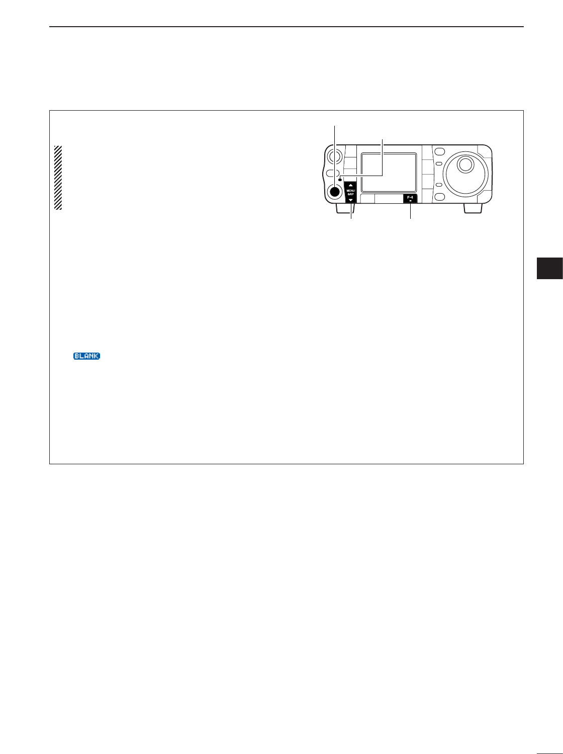
110
8
MEMORY OPERATION
8
This is useful for transferring frequency and operat-
ing mode while operating in memory mode.
When you have changed the frequency or operat-
ing mode in the selected memory channel.
• Displayed frequency and mode are transferred.
• Programmed frequency and mode in the memory
channel are not transferred, and they remain in
the memory channel.
qPush [PBT/M-ch/RIT] momentarily to select the M-
ch/RIT function, if the twin PBT is selected.
•[PBT/M-ch/RIT] indicator (Green) goes out.
wSelect the menu M
-
2.
•Push and hold [MENU/GRP] for 1 sec. once or twice
to select the menu group M.
•Push [MENU/GRP] momentarily one or more times to
select the menu M
-
2.
ePush [F-4 V/M]momentarily to select the memory
mode.
rRotate [M-ch] to select the memory channel to be
transferred.
•“ ” appears if the selected memory channel is a
blank channel (and does not have contents). In this
case transferring is not possible.
tPush [F-4 V/M]for 1 sec. to transfer the frequency
and operating mode.
•Displayed frequency and operating mode are trans-
ferred to the VFO.
yPush [F-4 V/M]momentarily to select the VFO
mode.
[MENU/GRP]
[PBT/M-ch/RIT] indicator
[PBT/M-ch/RIT] switch/[M-ch] (inner) control
[F-4]
DTransferring in memory mode
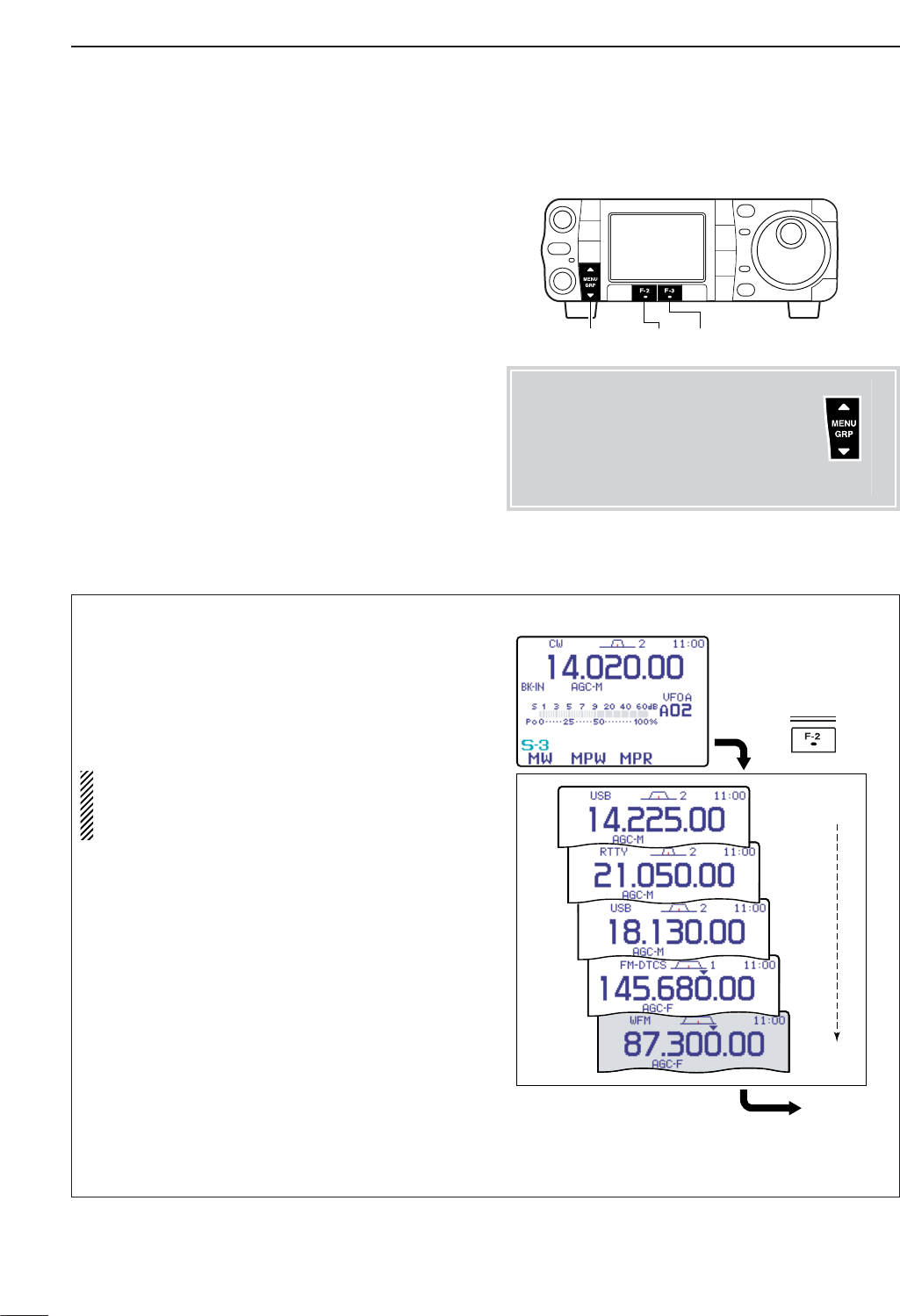
qSelect the menu S
-
3.
wPush [F-2 MPW]to program the frequency into a
memo pad.
When you write a 6th frequency and operating mode,
the oldest written frequency and operating mode are
automatically erased to make room for the new set-
tings.
NOTE:
Each memo pad must have its own unique
combination of frequency and operating mode;
memo pads having identical settings cannot be
written.
Displayed frequency and mode
MP5
MP4
MP3
MP2
MP1
The oldest written frequency
and mode are erased.
Newest
Oldest
Push
MPW
111
8MEMORY OPERATION
■Memo pads
The transceiver has a memo pad function to store fre-
quency and operating mode for easy write and recall.
The memo pads are separate from memory channels.
The default number of memo pads is 5, however, this
can be increased to 10 in initial set mode if desired
(p. 134).
Memo pads are convenient when you want to memo-
rize a frequency and operating mode temporarily, such
as when you find a DX station in a pile-up or when a
station is busy for a long time and you want to tem-
porarily search for other stations.
Use the transceiver’s memo pads instead of relying on
hastily scribbled notes that are easily misplaced.
[MENU/GRP] [F-2] [F-3]
DWriting frequencies and operating modes into memo pads
Menu group selection
Push [MENU/GRP] for 1 sec.
Selection from:
M
,
S
or
G
(Graphic)
Menu selection (Example: S)
Push [MENU/GRP] momentarily.
Selection from:
S
-
1
,
S
-
2
or
S
-
3
Either
Y or Z
Either
Y or Z
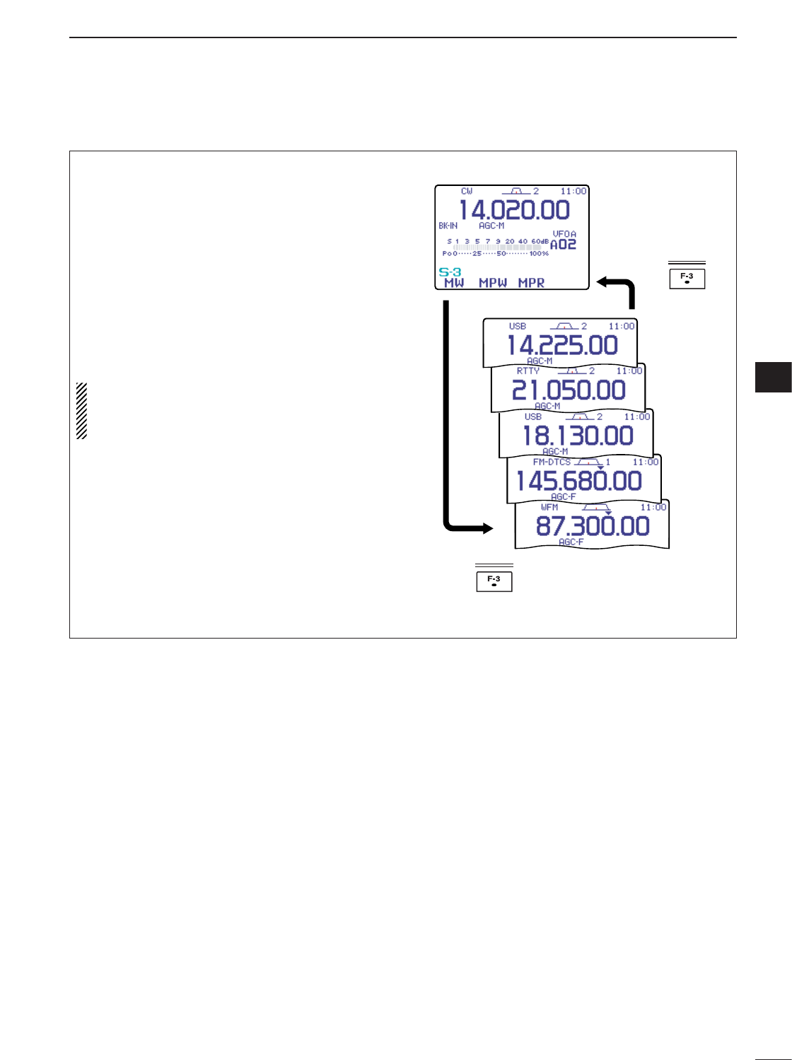
112
8
MEMORY OPERATION
8
You can simply call up the desired frequency and op-
erating mode of a memo pad by pushing [F-3 MPR]in
the S
-
3menu.
• Make sure S
-
3is selected in advance.
• Both VFO and memory modes can be used.
• The frequency and operating mode are called up, starting
from the most recently written.
When you call up a frequency and an operating mode
from memo pads with [F-3 MPR], the previously dis-
played frequency and operating mode are automati-
cally stored in a temporary pad. The frequency and
operating mode in the temporary pad can be recalled
by pushing [F-3 MPR]one or more times.
NOTE:
If you change the frequency or operating
mode called up from a memo pad, the frequency
and operating mode in the temporary pad are
erased.
MPR
MPR
MP5
MP4
MP3
MP2
MP1
VFO or memory mode
Push
Push
MEMO PADS
DCalling up a frequency from a memo pad

9
113
SCAN OPERATION
• Channels
For programmed scan: Program scan edge frequen-
cies into scan edge memory channels 1A and 1B.
(p. 103)
For memory scan: Program 2 or more memory chan-
nels except scan edge memory channels.
For memory select scan: Designate 2 or more mem-
ory channels as select memory channels—select a
memory channel, then push [F-2 SEL]in the S
-
2
menu (memory mode) to designate the channel as a
select memory channel.
For priority watch: Program 1 memory channel to be
watched.
• Scan resume ON/OFF
You can select the scan to resume or cancel when de-
tecting a signal, in the miscellaneous (others) set
mode, item “SCAN Resume.” Scan resume ON/OFF
must be set before operating a scan. See p. 135 for
ON/OFF setting and scan resume condition details.
•Scan speed
Scan speed can be selected from 2 levels, high or low,
in the miscellaneous (others) set mode. See p. 135 for
details.
• Squelch condition
PROGRAMMED SCAN
Repeatedly scans between two scan edge frequencies
(scan edge memory channels 1A and 1B).
This scan operates in VFO mode.
SELECTED MEMORY SCAN
Repeatedly scans all selected memory channels.
PRIORITY WATCH
Checks for signals on a memory while operating on a
VFO frequency.
This scan operates in memory mode.This scan operates in memory mode.
This scan operates in VFO mode.
Scan
Scan edge 1A or 1B Scan edge 1B or 1A
Jump
Mch 1 Mch 5
Memory
channel
VFO
frequency
Mch 2 Mch 3 Mch 4
Mch 6Mch 7Mch 99
MEMORY SCAN
Repeatedly scans all programmed memory channels.
Mch 1 Mch 5
Mch 2 Mch 3 Mch 4
Mch 6Mch 7Mch 99
BLANKBLANK
ß(select)
ß(select) ß(select)
ß(select) ß(select) ß(select) ß(select)
ß(select) ß(select)
ß(select)
SCAN
STARTS
WITH
PROGRAMMED
SCAN
MEMORY SCANS
PRIORITY WATCH
SQUELCH
OPEN
The scan continues
until it is stopped man-
ually, and does not
pause even if it de-
tects signals.
This is not applicable
when the scan re-
sume is OFF and a
programmable step
(more than 1 kHz) is
selected.
Scan pauses on each
channel when the
scan resume is ON;
not applicable when
OFF.
SQUELCH
CLOSED
Scan stops when detecting a signal.
If you set scan resume ON in the miscella-
neous (others)l set mode, the scan pauses for
10 sec. when detecting a signal, then re-
sumes. When a signal disappears while scan
is paused, scan resumes 2 sec. later.
■Scan types
■Preparation
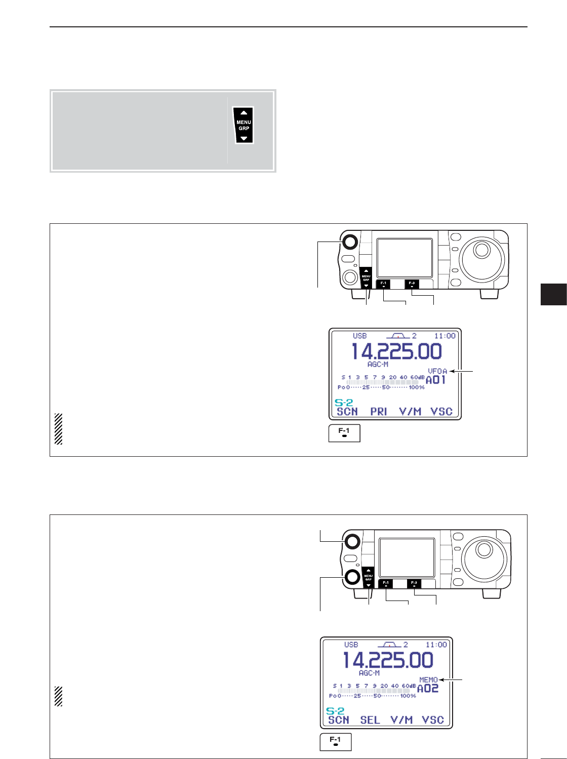
114
9
SCAN OPERATION
9
qSelect S
-
2.
wPush [F-3 V/M]to select VFO mode.
eSelect the desired operating mode.
•The operating mode can also be changed while scan-
ning.
rSet [RF/SQL] open or closed.
•See page a left for squelch condition.
•If the [RF/SQL] control function is set as “AUTO,” the
squelch is always open in SSB, CW and RTTY modes.
See pgs. 1, 35, 131 for details.
tPush [F-1 SCN]to start the scan.
•Decimal point blinks while scanning.
yWhen the scan detects a signal, the scan turns
OFF, pauses or ignores it depending on the re-
sume setting and the squelch condition.
uTo cancel the scan push [F-1 SCN].
NOTE:
If the same frequencies are programmed
into the scan edge memory channels 1A and 1B,
programmed scan does not start.
Select
VFO mode
then push [F-1 SCN]
[MENU/GRP] [F-1] [F-3]
[RF/SQL]
■Programmed scan operation
qSelect the desired memory bank, if necessary.
●
●
Push [PBT/M-ch/RIT] momentarily to select the
M-ch/RIT function, if the twin PBT is selected.
•[PBT/M-ch/RIT] indicator (Green) goes out.
●
●
Rotate [RIT] (outer) control to select the desired
memory bank.
wSelect S
-
2.
ePush [F-3 V/M]to select memory mode.
rClose the squelch with [RF/SQL].
tPush [F-1 SCN]to start the scan.
•Decimal point blinks while scanning.
yWhen the scan detects a signal, the scan stops or
pauses depending on the resume setting.
uTo cancel the scan push [F-1 SCN].
NOTE:
Two or more memory channels must be
programmed for memory scan to start.
Select
memory mode
then push [F-1 SCN]
[MENU/GRP] [F-1] [F-3]
[RF/SQL]
[RIT] (outer) control
■Memory scan operation
Menu group selection
Push [MENU/GRP] for 1 sec.
Selection from:
M
,
S
or
G
(Graphic)
Menu selection (Example: M)
Push [MENU/GRP] momentarily.
Selection from:
S
-
1
,
S
-
2
or
S
-
3
Either
Y or Z
Either
Y or Z
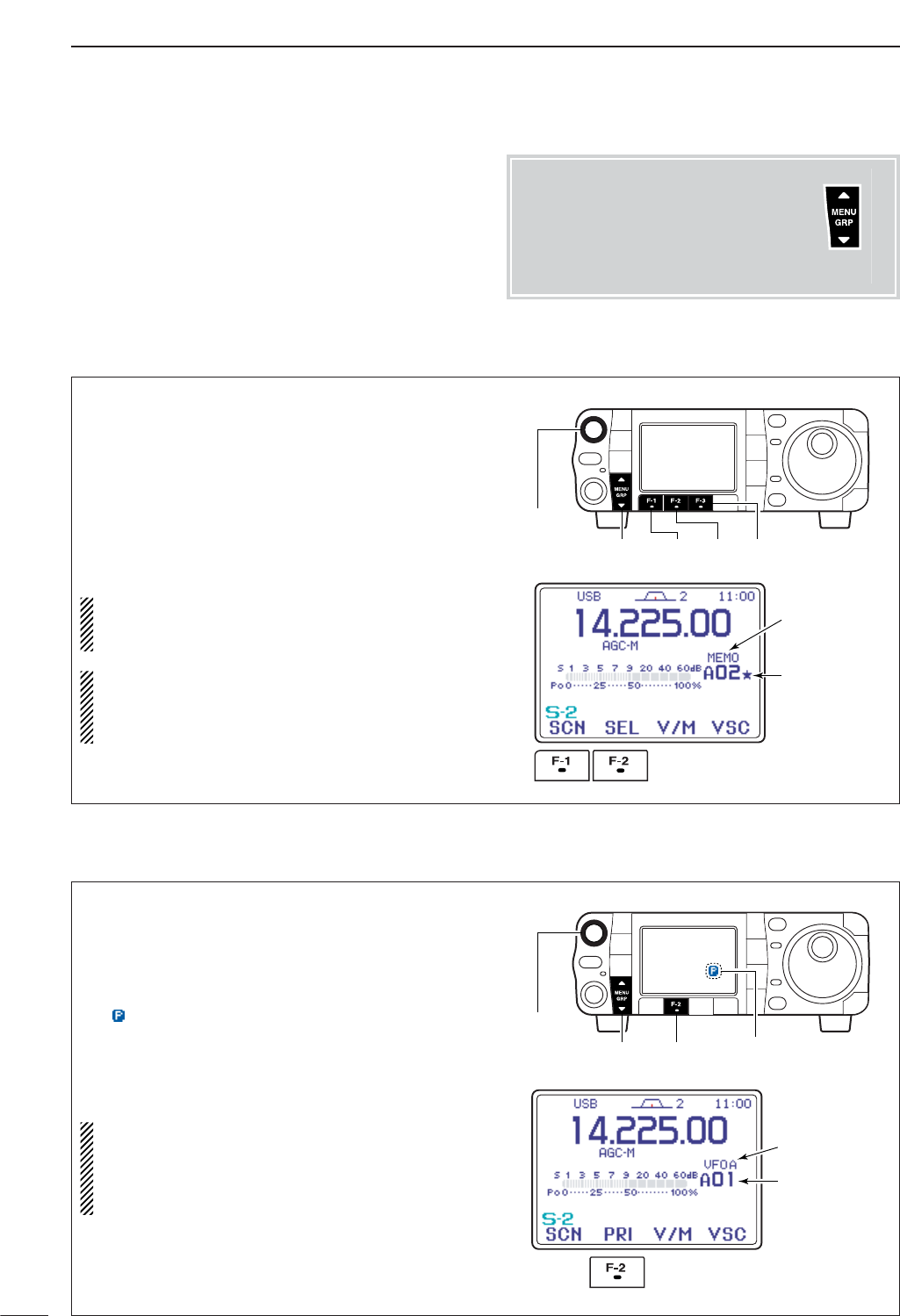
115
9SCAN OPERATION
qSelect VFO mode, then set a frequency.
wClose the squelch with [RF/SQL].
eSet the desired memory channel as the watching
channel.
rSelect S
-
2.
tPush [F-2 PRI]to start the priority watch.
• “ ” appears and decimal point blink while scanning.
yWhen the scan detects a signal, the scan pauses
for 10 sec. or until the signal disappears, depend-
ing on the resume setting.
uTo cancel the scan push [F-2 PRI].
NOTE:
The paused condition when detecting a sig-
nal differs depending on the scan resume condi-
tion. (p 134)
resume on: pauses for 10 sec.
resume off: pauses until the signal disappears.
Select
VFO mode.
Select watching
channel.
Push [F-2 PRI].
[MENU/GRP] [F-2]
[RF/SQL]
Appears while scanning
qSelect S
-
2.
wPush [F-3 V/M]to select memory mode.
eClose the squelch with [RF/SQL].
rPush [F-1 SCN]to start the memory scan.
•Decimal point blinks while scanning.
tPush [F-2 SEL]to change the memory scan to se-
lect memory scan.
yWhen the scan detects a signal, the scan stops or
pauses depending on the resume setting.
uTo cancel the scan push [F-1 SCN].
NOTE:
Two or more memory channels must be
designated as select memory channels for select
memory scan to start (see p. 106).
While scan function is not activate, pushing [F-2
SEL]sets the select memory channels ON or OFF.
And pushing and holding [F-2 SEL]for 2 sec.
clears the all select memory channels.
Designate
“★.”
Select
memory mode.
Push [F-1 SCN],
then push [F-2 SEL].
[MENU/GRP] [F-1] [F-2] [F-3]
[RF/SQL]
■Select memory scan operation
■Priority watch
Menu group selection
Push [MENU/GRP] for 1 sec.
Selection from:
M
,
S
or
G
(Graphic)
Menu selection (Example: M)
Push [MENU/GRP] momentarily.
Selection from:
S
-
1
,
S
-
2
or
S
-
3
Either
Y or Z
Either
Y or Z
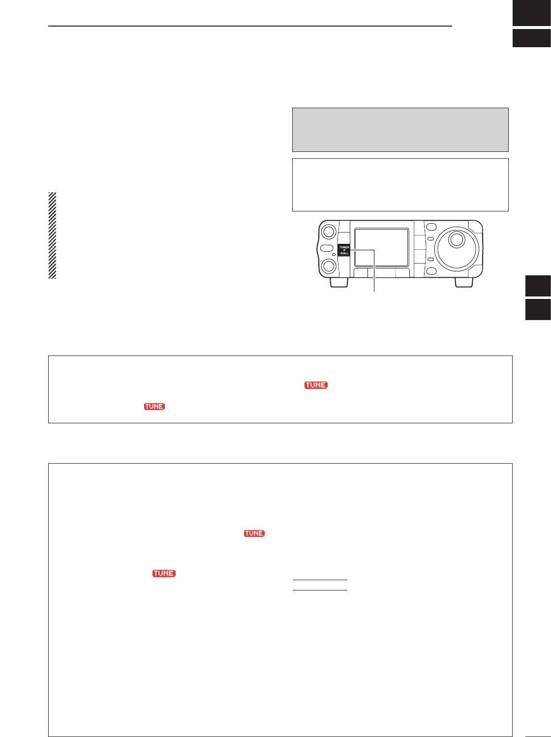
10
116
ANTENNA TUNER OPERATION
The AT-180 automatic antenna tuner matches the IC-
7000 to the connected antenna automatically. Once the
tuner matches an antenna, the variable capacitor angles
are memorized as a preset point for each frequency
range (100 kHz steps). Therefore, when you change the
frequency range, the variable capacitors are automati-
cally preset to the memorized point.
NOTE:
•The AT-180 can match both HF and 50 MHz
bands. However, operation is different for the HF
and 50 MHz bands.
• When connecting the AT-180, the IC-7000’s output
power must be set over the 10 W. Otherwise, the
AT-180 may not be tuned correctly. (AT-180’s min-
imum operating input power is 8 W.)
[TUNER/CALL]
The AT-180 cannot be used for the 144/430 MHz
bands. When operating on the 144/430 MHz band,
pushing [TUNER/CALL] selects the call channel
(p. 102).
CAUTION: NEVER transmit with the tuner ON
when no antenna is connected. This will damage
both the transceiver and antenna tuner.
■Optional AT-180
AUTOMATIC ANTENNA TUNER
operation
DTuner operation
• For the HF band:
Push [TUNER/CALL] to turn the tuner ON. The an-
tenna is tuned automatically during transmission
when the antenna SWR is higher than 1.5:1.
• When the tuner is ON, “ ” indication appears.
• For the 50 MHz band:
Push [TUNER/CALL] for 1 sec. to tune the antenna.
If “”indicator blinks slowly while transmitting,
push and hold [TUNER/CALL] for 1 sec. again to re-
tune the antenna.
DManual tuning
During SSB operation on HF bands at low voice lev-
els, the AT-180 may not be tuned correctly. In such
cases, manual tuning is helpful.
Push [TUNER/CALL] for 2 sec. to start manual tun-
ing.
•CW mode is selected, a side tone is emitted, and “”
indicator blinks; then, the previous mode is selected.
If the tuner cannot reduce the SWR to less than 1.5:1
after 20 sec. of tuning, “”indicator disappears.
In this case, check the following:
• the antenna connection and feedline
• the antenna SWR (p. 36; meter function)
Through inhibit (HF bands only)
The AT-180 has a through inhibit condition. When se-
lecting this condition, the tuner can be used at poor
SWR’s. In this case, automatic tuning in the HF bands
activates only when exceeding SWR 3:1. Therefore,
manual tuning is necessary each time you change the
frequency. Although termed “through inhibit,” the tuner
will be “through” if the SWR is higher than 3:1 after
tuning.
• Tuner sensitive condition (HF bands only)
If you require critical tuning at any time during trans-
mission, select the tuner sensitive condition. See
p. 133 for selection.
• Automatic tuner start (HF bands only)
If you want to turn OFF the tuner under conditions of
VSWR 1.5:1 or less, use “automatic tuner on” and
turn the tuner OFF. See p. 132 for turning the function
ON and OFF.
CONVENIENT
9
10
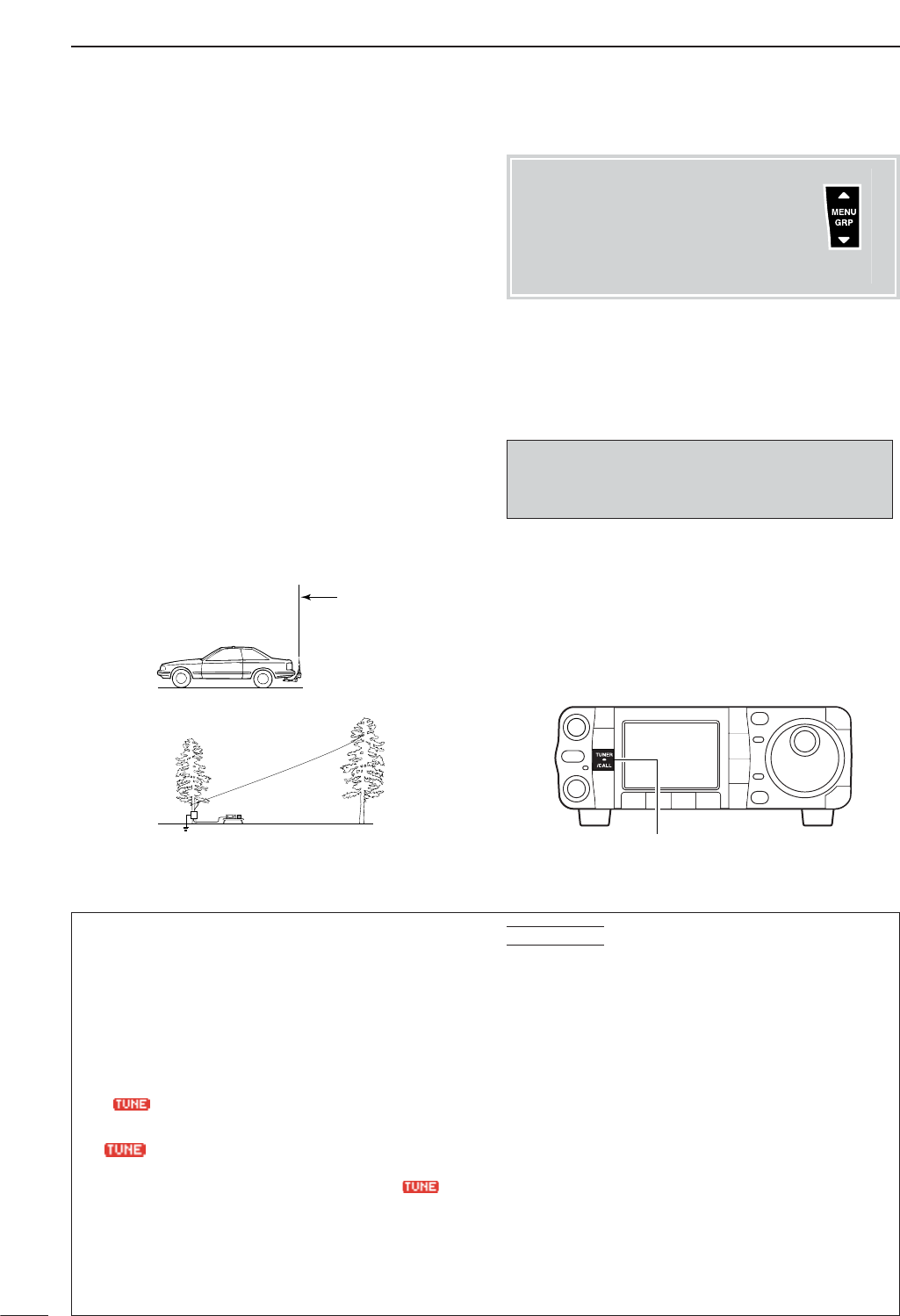
DAH-4 operation
117
10 ANTENNA TUNER OPERATION
Tuning is required for each frequency. Be sure to re-
tune the antenna before transmitting when you
change the frequency—even slightly.
qSet the desired frequency in an HF band.
•The AH-4 will not operate on frequencies outside of
ham bands.
wPush [TUNER/CALL] for 1 sec.
•“ ” indicator and “CW” appears while tuning.
e“”indicator stays ON when tuning is com-
plete.
•When the connected wire cannot be tuned, “”in-
dicator blinks, and the AH-4 is bypassed and the an-
tenna wire is connected to the antenna connector on
the transceiver directly.
rTo bypass the AH-4 manually, push [TUNER/
CALL].
• PTT tune function
The AH-4 is always tuned when the PTT is pushed
after the frequency is changed (more than 1%). This
function removes the “push and hold [TUNER/CALL]”
operation and activates first transmission on the new
frequency. This function is turned ON in the miscella-
neous (others) set mode (p. 133).
CONVENIENT
■Optional AH-4
AUTOMATIC ANTENNA TUNER
operation
The AH-4 matches the IC-7000 to a long wire antenna
more than 7 m/23 ft long (3.5 MHz and above).
• See p. 20 for connection.
•See the AH-4 instruction manual for AH-4 installation and
antenna connection details.
NEVER operate the AH-4 without an antenna wire.
The tuner and transceiver will be damaged.
NEVER operate the AH-4 when it is ungrounded.
Transmitting before tuning may damage the trans-
ceiver. Note that the AH-4 cannot tune when using a
1⁄2hlong wire or multiple of the operating frequency.
[TUNER/CALL]
RDANGER!: HIGH VOLTAGE!
NEVER touch the antenna element while tuning or
transmitting.
AH-4 setting example:
For mobile operation
For outdoor operation
Long wire
Optional AH-2b
antenna element
Menu group selection
Push [MENU/GRP] for 1 sec.
Selection from:
M
,
S
or
G
(Graphic)
Menu selection (Example: M)
Push [MENU/GRP] momentarily.
Selection from:
S
-
1
,
S
-
2
or
S
-
3
Either
Y or Z
Either
Y or Z
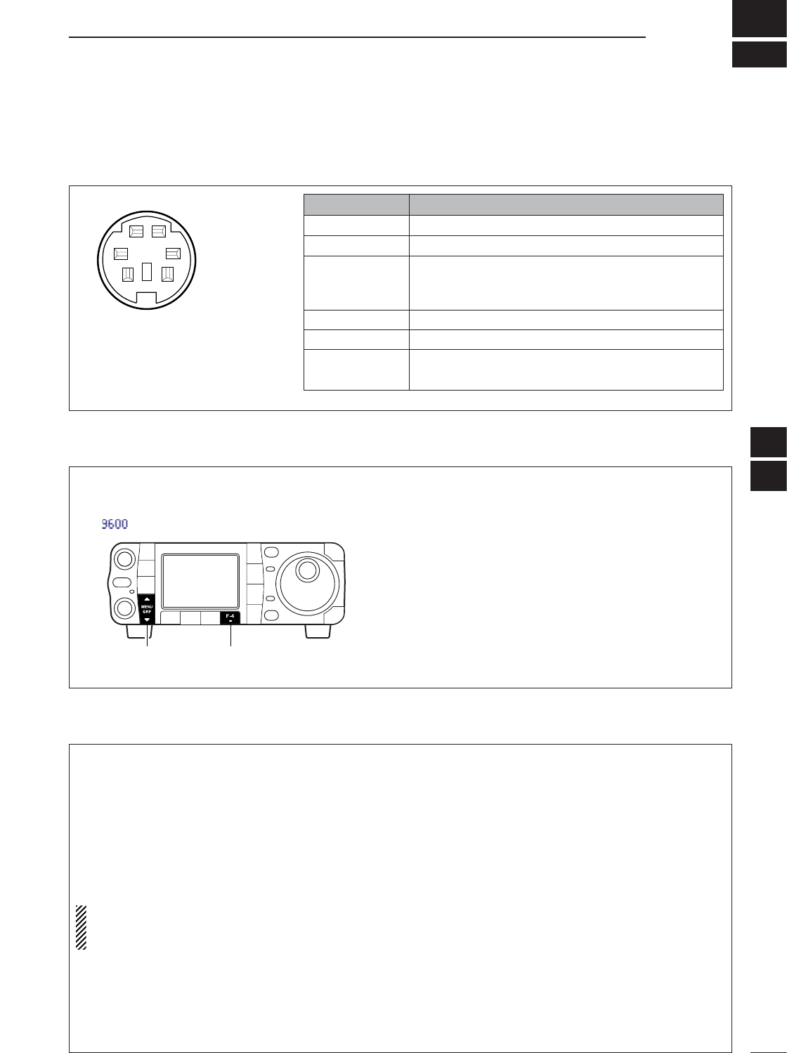
11
118
PACKET OPERATION
■Packet operation
qw
e
y
t
r
PIN #/NAME DESCRIPTION
q DATA IN Communication data input.
w GND Ground for DATA IN, DATA OUT and AF OUT.
Transmits when grounded.
e PTTP When grounded, microphone input (pin 6) of [MIC]
connector will be disconnected.
r DATA OUT Outputs 9600 bps receive data.
t AF OUT Outputs 1200 bps receive data.
y SQL Squelch output.
Goes to ground when squelch opens.
Rear panel view
DAdjusting the data speed
qSelect M
-
3.
wPush [F-4 9600]to select the 9600 mode ON and
OFF.
•“”appears when the 9600 mode is activated.
[MENU/GRP] [F-4]
DAdjusting the transmit signal output from the TNC
When setting data transmission speed to 9600 bps,
the data signal coming from the TNC is applied ex-
clusively to the internal limiter circuitry to automati-
cally maintain bandwidth.
NEVER apply data levels from the TNC of over 0.6
Vp-p, otherwise the transceiver will not be able to
maintain the band width and may possibly interfere
with other stations.
NOTE: Read the instructions supplied with your
TNC carefully before attempting packet operation
with the IC-7000.
1.When using a level meter or synchroscope, adjust
the TX audio level (DATA IN level) from the TNC as
follows.
0.4 Vp-p (0.2 Vrms): recommended level
0.2–0.5 Vp-p (0.1–0.25 Vrms): acceptable level
2.When not using a measuring device.
➀Connect the IC-7000 to a TNC.
➁Enter a test mode (“CAL”, etc.) on the TNC, then
transmit some test data.
➂When the transceiver fails to transmit test data or
transmits sporadically ([TX] indicator doesn’t light
red or blinks):
- Decrease the TNC output level until [TX] indica-
tor lights red continuously.
When transmission is not successful even though
[TX] indicator lights red continuously:
-Increase the TNC output level.
DData socket
10
11
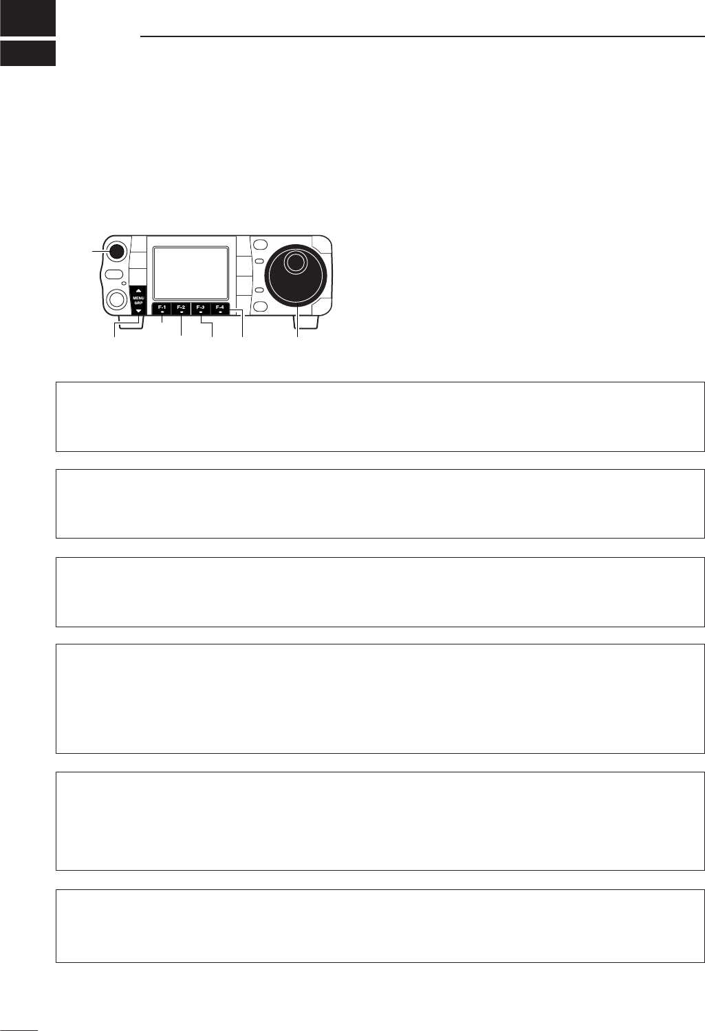
12
119
CLOCK AND TIMERS
This transceiver has a built-in 24-hour clock with
power-off timer function. The clock indication is always
displayed except after pushing [F-INP/ENT] (HM-151).
• Set mode operation
qPush [AF(
SET
)] momentarily to enter the set mode
menu.
wPush [F-3 TIME]to enter the time set mode.
ePush [F-1 ≤]or [F-2 ≥]to select the desired item.
rRotate [DIAL] to set or select the desired value or
condition.
•Push [F-4 DEF]for 1 sec. to select a default value or
condition.
tPush [Z(
MENU
/
GRP
)] twice to exit the set mode.
[DIAL][MENU/GRP]
[AF]
[F-1]
[F-2] [F-3] [F-4]
■Time set mode
CLOCK2 Offset
This item sets the desired off-set time period for the
clock 2 indication within –24:00 to +24:00 in 5 min.
steps.
•Push [F-4 DEF]for 1 sec. to set the default value.
± 0:00
(default)
+ 9:00
Rotate [DIAL] to set the
time.
Time (Now)
This item sets the current time for the built-in 24-hour
clock.
15:00
Rotate [DIAL], then push [F-3 SET]to set the time.
CLOCK2 Function
This item turns the second clock indication ON and
OFF instead of 1st clock.
The clock 2 is convenient to indicate the UTC and
other country’s local time, etc.
•Push [F-4 DEF]for 1 sec. to set the default value.
ON
The clock 2 is displayed in-
stead of the 1st clock indica-
tion.
OFF
The clock 2 does not dis-
play. (default)
Auto Power OFF
This item sets the power-off period for automatic shut-
down after the power-on timer has turned power ON.
60min
Push [F-3 SET]to enter the time.
Year
This item sets the current year. 2005
Rotate [DIAL], then push [F-3 SET]to set the year.
Date
This item sets the current date. 3-15(Tue)
Rotate [DIAL], then push [F-3 SET]to set the date.
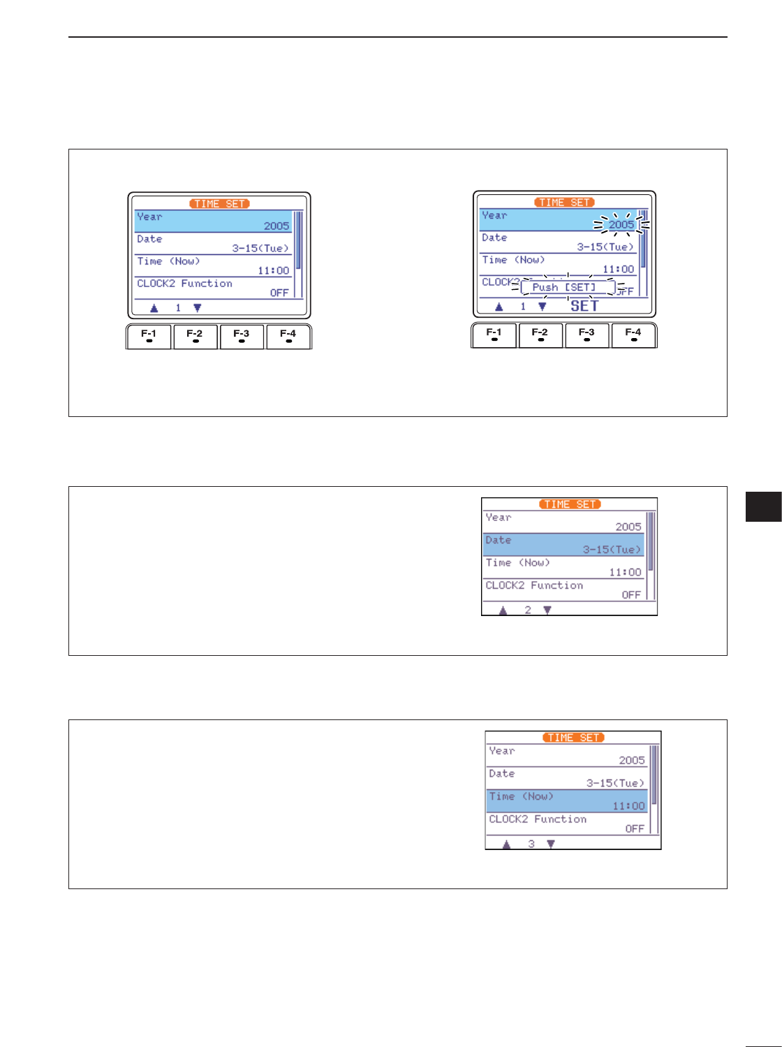
120
12
CLOCK AND TIMERS
12
DSetting the current year
qEntering time set mode, push [F-1 ≤]to select
“Year” item.
wSet the current year using [DIAL].
•“Push [SET]” blinks.
ePush [F-3 SET]to enter the set year.
•Push [Z(
MENU
/
GRP
)] to cancel the setting.
rPush [Z(
MENU
/
GRP
)] twice to exit time set mode.
DSetting the current date
qEntering time set mode, push [F-1 ≤]or [F-2 ≥]to
select “Date” item.
wRotate [DIAL] to set the current date.
•“Push [SET]” blinks.
ePush [F-3 SET]to enter the set date.
•Push [Z(
MENU
/
GRP
)] to cancel the setting.
rPush [Z(
MENU
/
GRP
)] twice to exit time set mode.
DSetting the current time
qEntering time set mode, push [F-1 ≤]or [F-2 ≥]to
select “Time (Now)” item.
wRotate [DIAL] to set the current time.
•“Push [SET]” blinks.
ePush [F-3 SET]to enter the set time.
•Push [Z(
MENU
/
GRP
)] to cancel the setting.
rPush [Z(
MENU
/
GRP
)] twice to exit time set mode.
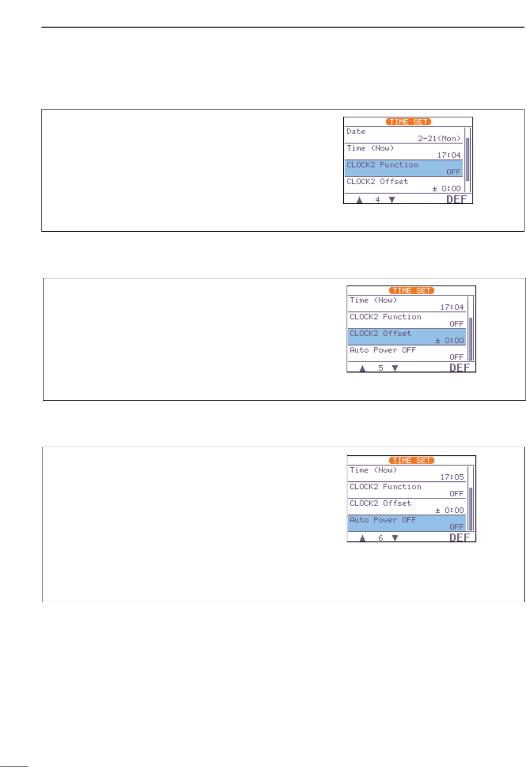
DAuto power OFF activity
121
12 CLOCK AND TIMERS
DClock2 function activity
DClock2 offset setting
qEntering time set mode, push [F-1 ≤]or [F-2 ≥]to
select “CLOCK2 Function” item.
wSelect the CLOCK2 function activity using [DIAL].
ePush [Z(
MENU
/
GRP
)] twice to exit time set mode.
qEntering time set mode, push [F-1 ≤]or [F-2 ≥]to
select “CLOCK2 Offset” item.
wRotate [DIAL] to set the offset time within –24:00
to +24:00 in 5min. steps.
ePush [Z(
MENU
/
GRP
)] twice to exit time set mode.
The transceiver can be set to automatically turn OFF
after a specified period is with beep when no opera-
tion is performed. The power-off period can be set to
30–120 min. in 30 min. steps.
qEntering time set mode, push [F-2 ≥]to select
“Auto Power OFF” item.
wSet the desired power-off time using [DIAL].
•“Push [SET]” blinks.
ePush [F-3 SET]to enter the set time.
•Push [Z(
MENU
/
GRP
)] to cancel the setting.
rPush [Z(
MENU
/
GRP
)] twice to exit timer set mode.
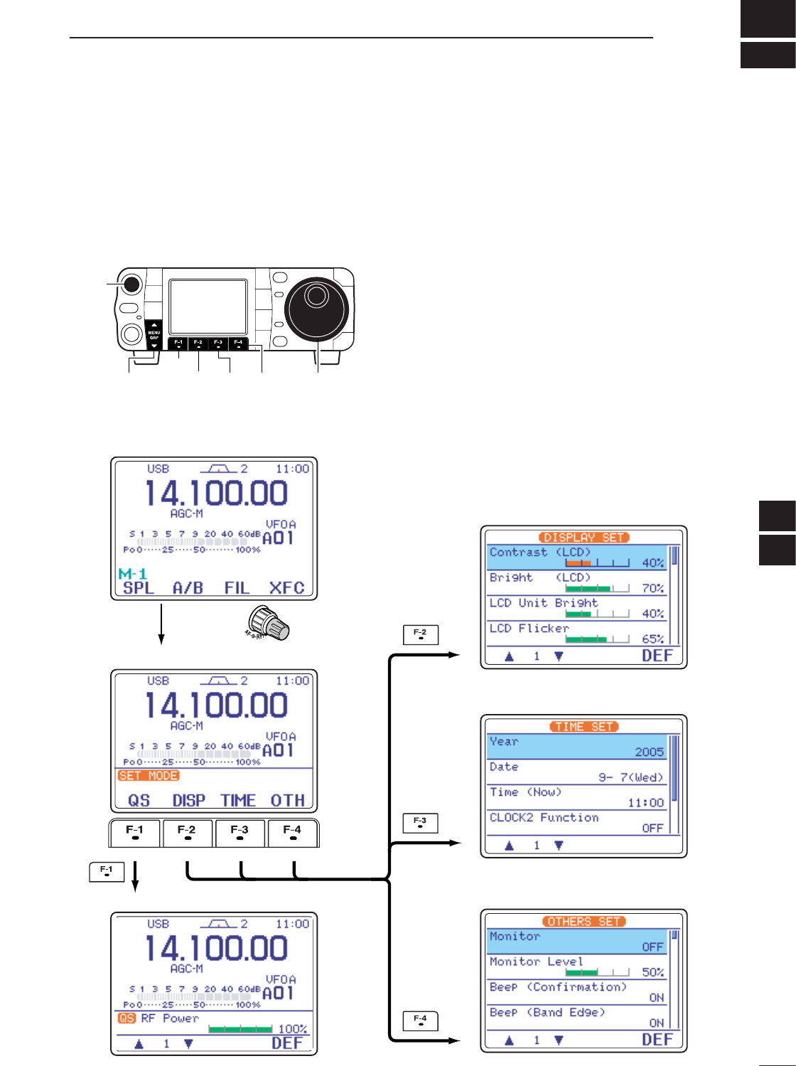
13
122
SET MODE
Set mode is used for programming infrequently
changed values or conditions of functions. This trans-
ceiver has a quick set mode, display set mode, timer
set mode and miscellaneous (others) set mode.
• Set mode operation
qPush [AF(
SET
)] momentarily to enter the set mode
menu.
wPush [F-1 QS],[F-2 DISP],[F-3 TIME]or [F-4
OTH]to enter the desired set mode.
ePush [F-1 ≤]or [F-2 ≥]to select the desired item.
rSet the desired condition using [DIAL].
•Push [F-4 DEF]for 1 sec. to select a default condition
or value.
tPush [Z(
MENU
/
GRP
)] twice to exit the set mode.
[DIAL][MENU/GRP]
[AF]
[F-1]
[F-2] [F-3] [F-4]
• Quick set mode (p. 123)
• Start up screen
• Set mode menu
• Display set mode (p. 126)
• Time set mode (p. 119)
• Miscellaneous (others) set mode (p. 130)
Push
[AF]
momentarily
■Set mode description
12
13
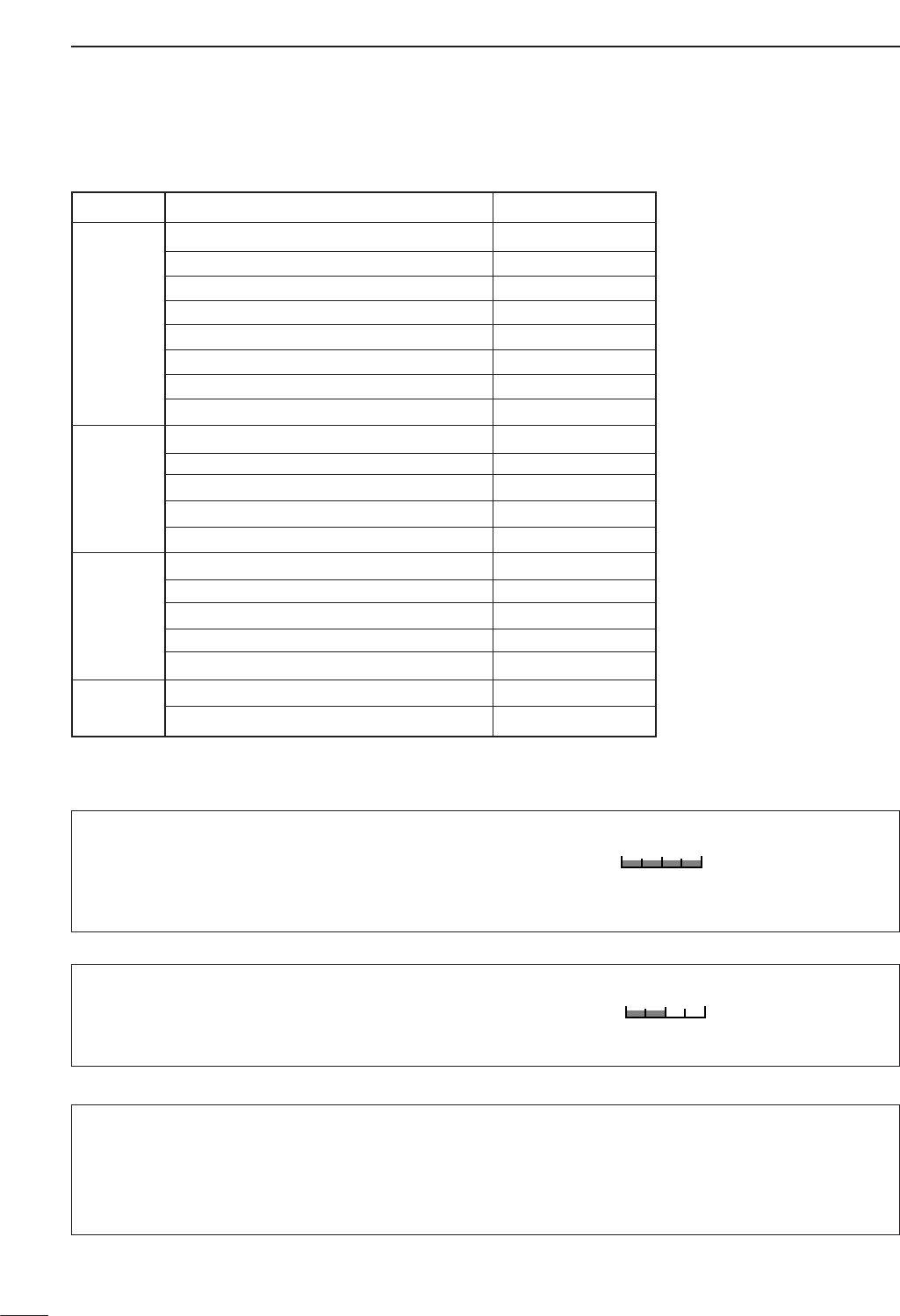
■Quick set mode
RF Power (all modes)
This item adjusts the RF output power. The RF out-
put power can be adjusted from 0 to 100% in 1 %
steps.
100%
100% (default)
MIC Gain (SSB/AM/FM modes)
This item adjusts microphone gain from 0 to 100% in
1% steps.
50%
50% (default)
123
13 SET MODE
Mode Set mode item Default setting
1RF Power 100%
2MIC Gain 50%
3SSB TBW (WIDE) L 100 [Hz]
SSB 4 SSB TBW (WIDE) H 2900 [Hz]
5SSB TBW (MID) L 300 [Hz]
6SSB TBW (MID) H 2700 [Hz]
7SSB TBW (NAR) L 500 [Hz]
8SSB TBW (NAR) H 2500 [Hz]
1RF Power 100%
2Key Speed 20WPM
CW 3 CW Pitch 600 [Hz]
4Side Tone Level 50%
5Side Tone Level Limit ON
1RF Power 100%
2Twin Peak Filter OFF
RTTY 3 RTTY Mark Frequency 2125 [Hz]
4RTTY Shift Width 170 [Hz]
5RTTY Keying Polarity Normal
AM 1RF Power 100%
FM/WFM 2MIC Gain 50%
SSB TBW (WIDE) L (SSB mode)
These items set the transmission passband width for
wide setting by selecting the lower and higher fre-
quencies.
Lower freq. : 100 (default), 200, 300 and 500 Hz
100
100 Hz (default)

124
13
SET MODE
13
SSB TBW (WIDE) H (SSB mode)
These items set the transmission passband width for
wide setting by selecting the lower and higher fre-
quencies.
Higher freq.: 2500, 2700, 2800 and 2900 Hz (default)
2900
2900 Hz (default)
■
Quick set mode (continued)
SSB TBW (MID) L (SSB mode)
These items set the transmission passband width for
middle setting by selecting the lower and higher fre-
quencies.
Lower freq. : 100, 200, 300 (default) and 500 Hz
300
300 Hz (default)
SSB TBW (MID) H (SSB mode)
These items set the transmission passband width for
middle setting by selecting the lower and higher fre-
quencies.
Higher freq.: 2500, 2700 (default) 2800 and 2900 Hz
2700
2700 Hz (default)
SSB TBW (NAR) H (SSB mode)
These items set the transmission passband width for
narrow setting by selecting the lower and higher fre-
quencies.
Lower freq. : 2500 (default), 2700, 2800 and 2900 Hz
2500
2500 Hz (default)
SSB TBW (NAR) L (SSB mode)
These items set the transmission passband width for
narrow setting by selecting the lower and higher fre-
quencies.
Lower freq. : 100, 200, 300 and 500 Hz (default)
500
500 Hz (default)
CW Pitch (CW mode)
This item adjusts the CW key speed. The key speed
can be selected from 300 to 900 Hz in 5 Hz steps.
600
600 Hz (default)
Key Speed (CW mode)
This item adjusts the CW key speed. The key speed
can be selected from 6 to 60 wpm.
20WPM
20 WPM (default)

125
13 SET MODE
■
Quick set mode (continued)
Twin Peak Filter (RTTY mode)
This item turns the twin peak filter ON and OFF. ON
Twin peak filter is ON
OFF
Twin peak filter is OFF. (de-
fault)
RTTY Mark Frequency (RTTY mode)
This item selects the RTTY mark frequency. RTTY
mark frequency is switched between 1275, 1615 and
2125 Hz.
2125
2125 Hz RTTY mark
frequency (default)
1275
1275 Hz RTTY mark
frequency
RTTY Shift Width (RTTY mode)
This item adjusts the RTTY shift width. There are 3
selectable values: 170, 200 and 425 Hz.
170
170 Hz RTTY shift
frequency (default)
425
425 Hz RTTY shift
frequency
RTTY Keying Polarity (RTTY mode)
This item selects the RTTY keying polarity. Normal or
reverse keying polarity can be selected.
When reverse polarity is selected, Mark and Space
are reversed.
- Normal : Key open/close = Mark/Space
- Reverse : Key open/close = Space/Mark
Normal
Normal polarity (default)
Reverse
Reverse polarity
Side Tone Level Limit (CW mode)
This item allows you to set a maximum volume level
for CW side tones. CW side tones are linked to the
[AF] control until a specified volume level is reached
— further rotation of the [AF] control will not increase
the volume of the CW side tones.
ON
CW side tone level is limited
with [AF] (default)
OFF
CW side tone level is linked
to [AF]
Side Tone Level (CW mode)
This item adjusts the CW side tone level from 0% to
100% in 1% steps.
See p. 43 for details.
50%
50% (default)
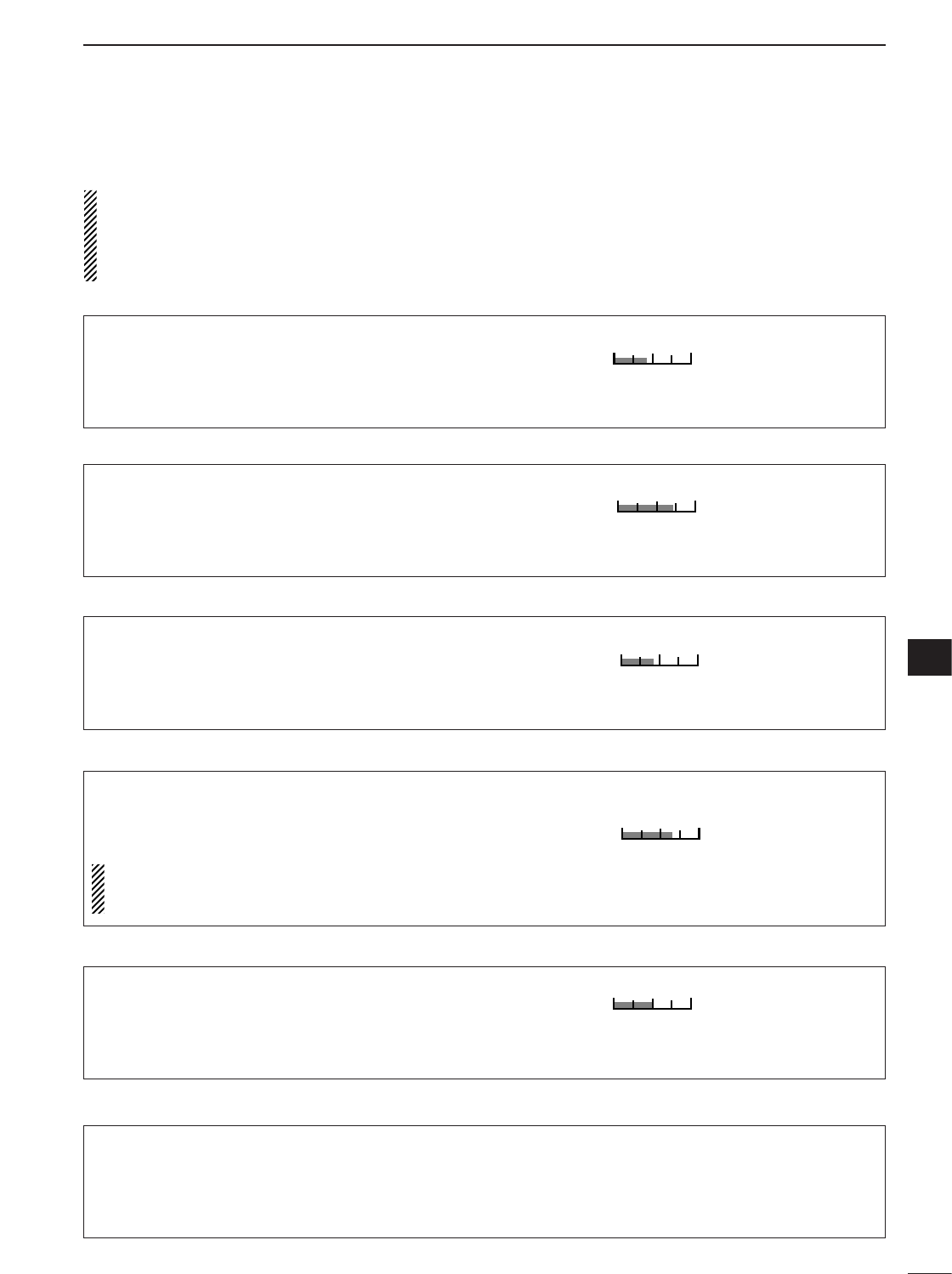
126
13
SET MODE
13
■Display set mode
To adjust the LCD contrast or backlight, wait until
the LCD becomes stable (10 min. or more after turn-
ing power ON). This is an inherent characteristic of
LCDs and LCD backlights and does not indicate a
transceiver malfunction.
1Contrast (LCD)
This item adjusts the contrast of the LCD from 0% to
100% in 1% steps.
40%
40% (default)
2Bright (LCD)
This item adjusts the brightness of the LCD from 0%
to 100% in 1% steps.
70%
70% (default)
3LCD Unit Bright
This item adjusts the brightness of the LCD unit from
0% to 100% in 1% steps.
40%
40% (default)
4LCD Flicker
This item adjusts the flicker of the LCD from 0% to
100% in 1% steps.
Icom recommends using the default value. But if
you feel the flicker on the LCD, and it is too con-
cerned, you adjust this item.
65%
65% (default)
5Backlight(Switches)
This item adjusts the brightness of the switches from
0% to 100% in 1% steps.
50%
50% (default)
6Display Type
This item sets the LCD screen type. There are 3 se-
lectable types: A, B, and C.
A
A-type LCD screen (default)

127
13 SET MODE
8Display Font Size
This item sets the font size of the frequency readouts.
Normal and large (2 sizes) are selectable.
Normal
Normal size (default)
■
Display set mode (continued)
9Meter Peak Hold
This item turns the meter peak hold function ON and
OFF.
When the meter peak hold function is ON, the highest
activated segment of the meter remains visible for 0.5
sec.; when OFF, the meter functions normally.
ON
Meter peak hold is ON
(default)
OFF
Meter peak hold is OFF
10 Filter Popup (PBT)
This item turns the popup indication ON and OFF for
the PBT function.
ON
Popup function is ON
(default)
OFF
Popup function is OFF
11 Filter Popup (FIL)
This item turns the popup indication ON and OFF for
the filter selection.
ON
Popup function is ON
(default)
OFF
Popup function is OFF
12 1Hz Mode Popup
This item turns the popup indication ON and OFF for
the 1 Hz tuning step function.
ON
Popup function is ON
(default)
OFF
Popup function is OFF
13 Scope CENTER/FIX Popup
This item turns the popup indication ON and OFF for
the Scope center/fix mode selection.
ON
Popup function is ON
(default)
OFF
Popup function is OFF
7Display Font Type
This item sets the font type of the frequency readouts.
Basic and Italic (2 fonts) are selectable.
Basic
Basic font (default)

128
13
SET MODE
13
■
Display set mode (continued)
14 TV Popup (CH Up/Down)
This item turns the popup indication ON and OFF for
the TV channel Up/Down operation.
ON
Popup function is ON
(default)
OFF
Popup function is OFF
15 TV Popup (P.AMP/ATT)
This item turns the popup indication ON and OFF for
the P.AMP/ATT setting on TV operation.
ON
Popup function is ON
(default)
OFF
Popup function is OFF
16 Voice TX Name Display
This item turns the indication of the voice TX memory
channel names ON and OFF on the voice TX mem-
ory channels of the voice TX menu.
ON
Voice TX memory names
are indicated on the voice
TX memory channels. (de-
fault)
OFF
Only the voice TX memory
channels are indicated.
17 Keyer Memory Display
This item turns the indication of the keyer memory
contents ON and OFF on the keyer memory channels
of the memory keyer send menu.
ON
Memory contents are indi-
cated on the keyer memory
channels. (default)
OFF
Only the keyer memory
channels are indicated.
18 DTMF Memory Display
This item turns the indication of the DTMF code se-
quence ON and OFF on the DTMF memory channels
of the DTMF send menu.
ON
DTMF code sequence are
indicated on the DTMF
memory channels. (default)
OFF
Only DTMF memory chan-
nels are indicated.
19 External Display
This item selects the indication size for external dis-
play.
1
Same indication ratio (1:1.8)
as transceiver display.
(default)
2
The indication ratio is 1:1.6.
20 Opening Message
This item turns the opening message screen indica-
tion capability ON and OFF.
ON
Opening message is ON
(default)
OFF
Opening message is OFF
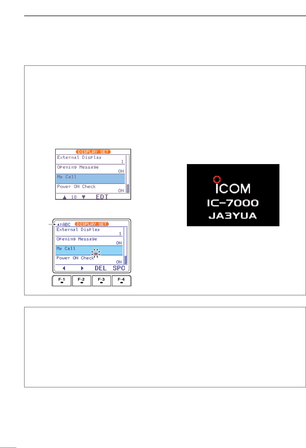
129
13 SET MODE
■
Display set mode (continued)
22 Power ON Check
This item selects the indication ON or OFF when turn-
ing power ON.
ON : The Transceiver briefly displays ‘Your Call
sign,’ ‘RF power,’ ‘Auto power OFF timer’ and
‘RIT/∂TX frequency’ when turning power ON.
• No-programmed or disactivated items are skipped.
OFF : The display goes directly to frequency indica-
tion at power ON.
ON
Power ON check is ON.
(default)
OFF
Power ON check is OFF.
21 My Call
Your call sign, etc. can be displayed in the opening
screen when turning power ON. Up to 10 characters
can be programmed.
Capital letters, numerals, some symbols (– / .) and
spaces can be used.
qPush [AF(
SET
)] momentarily, then [F-2 DISP]to
select the display set mode.
wPush [F-1 ≤]or [F-2 ≥]several times to select the
“18 My Call” item.
rPush [F-3 EDT]to edit.
• A cursor appears and blinks.
tInput the desired character by rotating [DIAL] or by
pushing the band key (on HM-151) for number
input.
•Push [Y(
MENU
/
GRP
)] to select the capital letters
([ABC]), numerals ([123]) or symbols ([etc]).
•Push [F-1 Å]or [F-2 Ç]for cursor movement.
•Push [F-3 DEL]to delete the selected character.
•Push [F-4 SPC]to input a space.
yPush [Z(
MENU
/
GRP
)] to input the set name.
• The cursor disappears.
uPush [Z(
MENU
/
GRP
)] twice to exit the set mode
screen.
• Opening screen example
Selected
character

130
13
SET MODE
13
■Miscellaneous (others) set mode
3Beep(Confirmation)
A beep sounds each time a switch is pushed to con-
firm it. This function can be turned OFF for silent op-
eration.
The volume level can be set described below.
ON
Confirmation beep ON
(default)
OFF
Confirmation beep OFF
4Beep(Band Edge)
A beep sounds when an operating frequency enters
or exits an amateur band. This functions independent
of the confirmation beep setting (above).
The volume level can be set described below.
ON
Band edge beep ON
(default)
OFF
Band edge beep OFF
5Beep Level
This item adjusts the volume level for (confirmation
and band edge) beep tones from 0% to 100% in 1%
steps. When beep tones are turned OFF, this setting
has no effect.
50%
50% (default)
1Monitor
This item sets the TX monitor function ON and OFF.
The monitor gain can be set described below.
ON
TX monitor function is
turned ON.
OFF
TX monitor function is
turned OFF. (default)
2Monitor Level
This item adjusts the transmit IF signal monitor level
from 0% to 100% in 1% steps.
See p. 89 for details.
50%
50% (default)
6Beep Level Limit
This item allows you to set a maximum volume level
for (confirmation and band edge) beep tones. The
beep tones are linked to the [AF] control until a spec-
ified volume level is reached — further rotation of the
[AF] control will not increase the volume of the beep
tones.
ON
Beep level is limited with
[AF] (default)
OFF
Beep level is linked to [AF]

131
13 SET MODE
7RF/SQL Control
The [RF/SQL] control can be set as the RF/squelch
control (default), the squelch control only (RF gain is
fixed at maximum) or ‘Auto’ (RF gain control in SSB,
CW and RTTY; squelch control in AM and FM).
See pgs. 1, 35 for details.
RF+SQL [RF/SQL] control as RF/squelch control
SQL [RF/SQL] control as squelch control
AUTO [RF/SQL] control as RF gain control in SSB,
CW and RTTY; squelch control in AM and
FM (default)
■
Miscellaneous (others) set mode (continued)
8Quick SPLIT
When this item is set to ON, pushing and holding [F-1
SPL](M
-
1) for 1 sec. sets the undisplayed VFO fre-
quency to the displayed VFO frequency plus the split
offset and activates split operation.
See p. 92 for details.
ON
Quick split ON
(default)
OFF
Quick split OFF
10 SPLIT LOCK
When this item is ON, [DIAL] can be used to adjust
the transmit frequency while pushing [XFC] even
while the lock function is activated.
See p. 91 for split frequency operation details.
ON
Split lock function ON
OFF
Split lock function OFF
(default)
9SPLIT Offset
This item sets the offset (difference between transmit
and receive frequencies) for the quick split function.
The offset frequency can be set from –9.999 MHz to
+9.999 MHz in 1 kHz steps.
0.000MHz
0.000 MHz offset
(default)
-9.999MHz
Minus 9.999 MHz offset
12 DUP Offset 50M
This item sets the offset (difference between transmit
and receive frequencies) for duplex operation. How-
ever, this setting is used to input the repeater offset
for the 50 MHz band.
The offset frequency can be set from 0.000 MHz to
+9.999 MHz in 1 kHz steps.
0.500MHz
0.5 MHz offset (default)
11 DUP Offset HF
This item sets the offset (difference between transmit
and receive frequencies) for duplex operation. How-
ever, this setting is used to input the repeater offset
for an HF band only.
The offset frequency can be set from 0.000 MHz to
+9.999 MHz in 1 kHz steps.
0.100MHz
0.1 MHz offset (default)

132
13
SET MODE
13
■
Miscellaneous (others) set mode (continued)
15 One Touch Repeater
This item turns the one touch repeater function ON
(DUP-,DUP+) and OFF.
When [F-2 DUP](M-3) is pushed and held for 1 sec.,
the selected offset direction and programmed duplex
offset frequency (depending on the operating fre-
quency band) is set with the displayed frequency.
DUP-
Minus offset direction is se-
lected. (default)
OFF
One touch repeater function
is OFF.
14 DUP Offset 430M
This item sets the offset (difference between transmit
and receive frequencies) for duplex operation. How-
ever, this setting is used to input the repeater offset
for the 430 MHz band.
The offset frequency can be set from 0.000 MHz to
+9.999 MHz in 1 kHz steps.
5.000MHz
5 MHz offset (default)
13 DUP Offset 144M
This item sets the offset (difference between transmit
and receive frequencies) for duplex operation. How-
ever, this setting is used to input the repeater offset
for an 144 MHz band only.
The offset frequency can be set from 0.000 MHz to
+9.999 MHz in 1 kHz steps.
0.600MHz
0.6 MHz offset (default)
17 Tuner (Auto Start)
The optional AT-180
ANTENNA TUNER
has an automatic
start capability which starts tuning if the SWR is
higher than 1.5–3:1.
When “OFF” is selected, the tuner remains OFF even
when the SWR is poor (1.5–3:1). When “ON” is se-
lected, automatic tune starts even when the tuner is
turned OFF.
Even when “ON” is selected, automatic tune does
not start for the 50 MHz band.
ON
Automatic tune function is
ON.
OFF
Automatic tune function is
OFF. (default)
16 Auto Repeater
This item turns the auto repeater function ON-1 (auto
duplex setting), ON-2 (auto duplex setting and acti-
vating tone encoder) or OFF.
See p. 65 for details concerning the auto repeater
function.
ON-1
Auto duplex setting is ON.
(default)
OFF
Auto repeater function is
OFF.

133
13 SET MODE
20 VSEND Select
This item select the [ACC] (pin 7) output.
“ON” : VSEND is for the 144/430 MHz; HSEND
is for the HF/50 MHz.
“UHF Only”: VSEND is for the 430 MHz; HSEND is
for the HF/50/144 MHz.
“OFF” : VSEND is not used; HSEND is for all
bands.
ON
VSEND is for 144/430 MHz.
(default)
■
Miscellaneous (others) set mode (continued)
19 [TUNER] Switch
You can set [TUNER/CALL] key’s action from “Auto”
and “Manual.”
Auto Optional antenna tuner is activated auto-
matically when tuner is ON. (default)
Manual Optional antenna tuner is activated,
when [TUNER/CALL] is pushed.
18 Tuner (PTT Start)
When an optional AH-4
ANTENNA TUNER
is connected,
tuning can be started automatically at the moment the
PTT is pushed.
This function activates for HF band only.
ON
Tuning starts when pushing
[PTT] on a new frequency.
OFF
Tuning starts only when
[TUNER] is pushed. (default)
22 SPEECH Language
This item selects language for the speech function.
You can select between English and Japanese as the
SPEECH language.
English
English announcement
(default)
Japanese
Japanese announcement
23 SPEECH Speed
This item selects the speech speed between faster or
slower synthesizer output.
HIGH
Faster announcement
(default)
LOW
Slower announcement
21 SPEECH Level
This item adjusts the volume level for speech function
from 0% to 100% in 1% steps.
50%
50% (default)

134
13
SET MODE
13
■
Miscellaneous (others) set mode (continued)
24 SPEECH S-Level
You can have frequency, mode and signal level an-
nouncement. Signal level announcement can be de-
activated if desired.
When “OFF” is selected, the signal level is not an-
nounced.
ON
Signal level announcement
(default)
OFF
No signal level
announcement
25 SPEECH [MODE] Switch
This irem selects the operating mode speech capa-
bility when [MODE] is pushed.
When “ON” is selected, the selected operating mode
is announced at pushing [MODE].
ON
Operating model announce-
ment with [MODE]
OFF
No operating mode an-
nouncement with [MODE]
(default)
26 Memopad Numbers
This item sets the number of memo pad channels
available. 5 or 10 memo pads can be set.
5
5 memo pads
(default)
10
10 memo pads
29 MAIN DIAL Auto TS
This item sets the auto tuning step function. When ro-
tating [DIAL] rapidly, the tuning step automatically
changes several times as selected.
There are 2 type of auto tuning steps: HIGH (Fastest)
and LOW (Faster).
HIGH Auto tuning step is turned ON.
Fastest tuning step during rapid rotation
(default)
LOW Auto tuning step is turned ON.
Faster tuning step during rapid rotation
OFF Auto tuning step is turned OFF.
27 SCAN Speed
This item sets the rate at which channels or frequen-
cies are scanned during scan operations. High and
low can be selected.
HIGH
Scan is faster.
(default)
LOW
Scan is slower.
28 SCAN Resume
This item sets the scan resume function ON and OFF.
“ON” : Scan resumes 10 sec. after stopping on
a signal (or 2 sec. after a signal disap-
per).
“OFF” : Scan does not resume after stopping on
a signal. For the priority watch, setting to
OFF pauses the watch until the signal
disappears and scan resumes.
ON
Scan resume function is
ON. (default)
OFF
Scan resume function is
OFF.

135
13 SET MODE
■
Miscellaneous (others) set mode (continued)
30 HM-151 [F-1]
This item programmes for one of several functions to
[F-1] key of HM-151. Programmable key assignments
are described as below.
MPW
Memo pad write is pro-
grammed. (default)
ANF
Auto notch filter is pro-
grammed.
31 HM-151 [F-2]
This item programmes for one of several functions to
[F-2] key of HM-151. Programmable key assignments
are same as above.
MPR
Memo pad read is pro-
grammed. (default)
NB
Noise blanker function is
programmed.
34 SSB/CW Synchronous Tuning
This item selects the displayed frequency shift func-
tion from ON and OFF.
When this function is activate, the receiving signal
can be kept to receive even when the operating mode
is changed between SSB and CW.
The frequency shifting value may differ according
to the CW pitch setting.
ON
The displayed frequency
shifts when the operating
mode is changed between
SSB and CW.
OFF
The displayed frequency
does not shift.
(default)
32 MIC Up/Down Speed
This item sets the rate at which frequencies are
scanned when the microphone (HM-151) [Y]/[Z]
keys are pushed and held. High or low can be se-
lected.
HIGH
High speed (default,
50 tuning steps/sec.)
LOW
Low speed
(25 tuning steps/sec.)
33 Quick RIT/∂TX Clear
This item selects the RIT/∂TX frequency clearing in-
struction with [F-3 CLR]key.
See pgs. 75, 88 for deatails.
ON
Clears the RIT/∂TX fre-
quency when [F-3 CLR]is
pushed momentarily.
OFF
Clears the RIT/∂TX fre-
quency when [F-3 CLR]is
pushed and held for 1 sec.
(default)
“P.AMP/ATT” (Preamplifier/attenuator),
“NB” (Noise blanker),
“NR” (Noise reduction),
“MNF” (Manual notch filter),
“ANF” (Auto notch filter),
“TS” (Tuning step),
“SPL” (Split operation),
“A/B” (VCO A/B selection),
“MCL” (Memory clear),
“BNK” (Bank selection),
“COM” (Speech compressor),
“AGC” (AGC selection),
“TBW” (TX filter width),
“DUP” (Duplexer),
“TON” (FM tone operation),
“MET” (Meter selection),
“VSC” (Voice squelch control),
“MPW” (Memo pad write),
“MPR” (Memo pad read),
“<SCOPE>” (Scope selection),
“<METER>” (Multi-meter selection)

136
13
SET MODE
13
■
Miscellaneous (others) set mode (continued)
35 CW Normal Side
Selects the carrier point of CW mode from LSB and
USB.
LSB
The carrier point is set to
LSB side.
(default)
USB
The carrier point is set to
USB side.
37 KEYER 1st Menu
This item selects the first appearing menu when [F-2
KEY](S-1) is pushed, from “KEYER-SEND” or
“KEYER-Root.”
KEYER-SEND
Keyer send menu is se-
lected. (default)
KEYER-Root
Keyer root menu is selected.
38 DTMF 1st Menu
This item selects the first appearing menu when [F-2
DTM](S-1) is pushed, from “DTMF-SEND” or
“DTMF-Root.”
DTMF-SEND
DTMF send menu is se-
lected. (default)
DTMF-Root
DTMF root menu is se-
lected.
36 VOICE 1st Menu
This item selects the first appearing menu when [F-1
VO](S-1) is pushed, from “VOICE-RX/TX” or
“VOICE-Root.”
VOICE-RX/TX
Voice RX/TX menu is se-
lected. (default)
VOICE-Root
Voice root menu is selected.
39 Mode Select (SSB)
This item inhibits the selection of SSB (LSB/USB)
modes, and allows you to simplify operation during
normal operation.
For example if you are operating mobile and only plan
on using FM and AM modes, sets all other modes
(SSB, CW, RTTY, WFM) to OFF, thereby making se-
lection of AM or FM quick and easy.
ON
SSB modes are selectable.
(default)
OFF
SSB modes are inhibited.
40 Mode Select (CW)
This item inhibits the selection of CW/CW-R modes,
and allows you to simplify operation during normal op-
eration.
ON
CW modes are selectable.
(default)
OFF
CW modes are inhibited.
41 Mode Select (RTTY)
This item inhibits the selection of RTTY/RTTY-R
modes, and allows you to simplify operation during
normal operation.
ON
RTTY modes are selectable.
(default)
OFF
RTTY modes are inhibited.
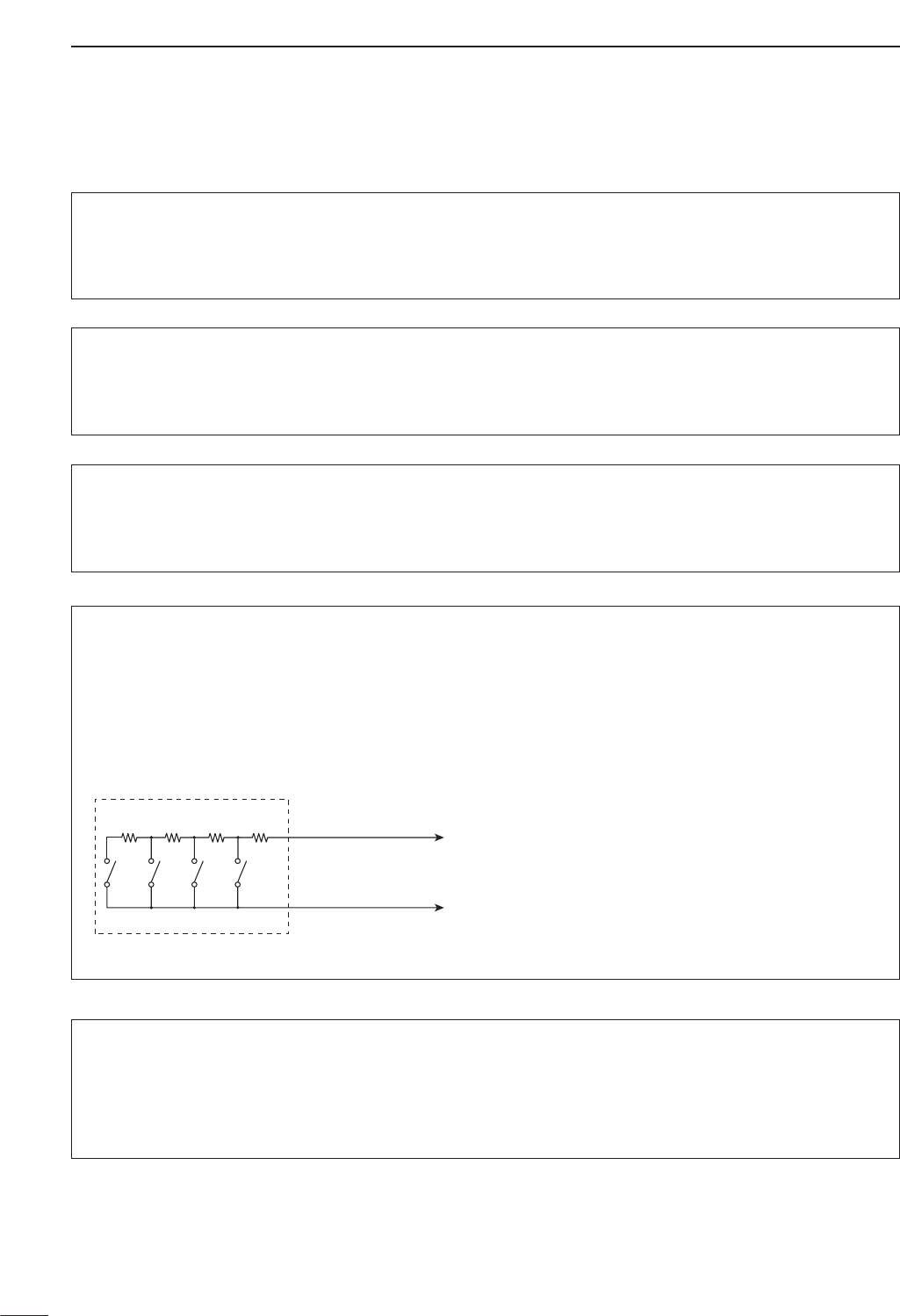
45 External Keypad (VOICE)
This item sets the external keypad capability and
function.
For your information
The following diagram shows the equivalent circuit of
an external keypad and connects to the pin 3 and
pin 7 of the [MIC] connector (p. 10).
ON : Pushing one of external keypad switches, transmits
the desired voice memory contents during a phone
mode (SSB, AM, FM) operation.
OFF : External keypad does not function.
(default)
To [MIC] connector pin e
To [MIC] connector pin u
1.5k1
±5%
1.5k1
±5%
2.2k1
±5%
4.7k1
±5%
S1
(T1/M1)
S2
(T2/M2)
S3
(T3/M3)
S4
(T4/M4)
USER EXTERNAL KEYPAD
46 External Keypad (KEYER)
This item sets the external keypad capability and
function.
User external keypad is same as above.
ON : Pushing one of external keypad switches, transmits
the desired memory keyer contents during CW
mode operation.
OFF : External keypad does not function. (default)
137
13 SET MODE
■
Miscellaneous (others) set mode (continued)
43 Mode Select (FM)
This item inhibits the selection of FM mode, and al-
lows you to simplify operation during normal opera-
tion.
ON
FM mode is selectable.
(default)
OFF
FM mode is inhibited.
44 Mode Select (WFM)
This item inhibits the selection of WFM mode, and al-
lows you to simplify operation during normal opera-
tion.
ON
WFM mode is selectable.
(default)
OFF
WFM mode is inihibited.
42 Mode Select (AM)
This item inhibits the selection of AM mode, and al-
lows you to simplify operation during normal opera-
tion.
ON
AM mode is selectable.
(default)
OFF
AM mode is inhibited.

138
13
SET MODE
13
■
Miscellaneous (others) set mode (continued)
48 CI-V Baud Rate
This item sets the data transfer rate. 300, 1200, 4800,
9600, 19200 bps and “Auto” are available.
When “Auto” is selected, the baud rate is automati-
cally set according to the connected controller or re-
mote controller.
Auto
Auto baud rate
(default)
19200
19200 bps
49 CI-V Address
To distinguish equipment, each CI-V transceiver has
its own Icom standard address in hexadecimal code.
The IC-7000’s address is 70h.
When 2 or more IC-7000’s are connected to an op-
tional CT-17
CI
-
V LEVEL CONVERTER
, rotate [DIAL] to
select a different address for each IC-7000 in the
range 01h to 7Fh.
70h
Address of 70h
(default)
7Fh
Address of 7Fh
50 CI-V Transceive
Transceive operation is possible with the
IC-7000
con-
nected to other Icom HF transceivers or receivers.
When “ON” is selected, changing the frequency, op-
erating mode, etc. on the IC-7000 automatically
changes those of connected transceivers (or re-
ceivers) and vice versa.
ON
Transceive ON
(default)
OFF
Transceive OFF
51 REF Adjust
This item adjusts the internal reference frequency
within 0 to 100% range in 1 % steps.
47 Front Keypad Type
This item selects the front keypad type connected to
the [MIC] connector of the controller.
Dot/Dash
Dot/Dash (default)
Ext Keypad
External keypad
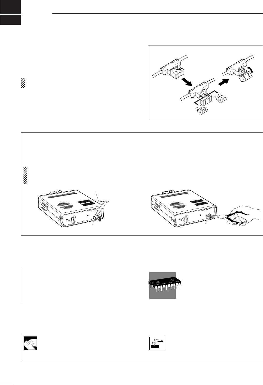
14
139
MAINTENANCE
If the transceiver becomes dusty or dirty,
wipe it clean with a dry, soft cloth.
AVOID the use of strong chemical solvents
such as thinner, benzine or alcohol to clean
the transceiver. These may damage the
transceiver’s surfaces.
■Fuse replacement
If a fuse blows or the transceiver stops functioning, try
to find the source of the problem, and replace the dam-
aged fuse with a new, rated fuse.
CAUTION: Disconnect the DC power cable from
the transceiver when changing a fuse.
The IC-7000 has three of fuses (DC power cable fuses
×2, circuitry fuse×1) installed for transceiver protection.
• DC power cable fuses ........................... ATC20 30 A
• Circuitry fuse ............................................ ATC20 5 A
CIRCUITRY FUSE REPLACEMENT
The 13.8 V DC from the DC power cable is applied to
all units in the IC-7000, except for the power ampli-
fier, through the circuitry fuse. This fuse is installed in
the FRONT unit.
RWARNING:NEVER attempt to remove fuse
coverusing your finger nails, this may result in in-
jury.
Fuse
Screw driver
Fuse cover
■Memory backup
All of the CPU’s memory is backed up by an EEP-
ROM (Electronically-Erasable Programmable Read-
Only Memory). All data you set, such as VFO,
memory, set mode contents, etc. is stored in this
EEPROM. There is no internal lithium battery.
■Cleaning
DC power cable fuse replacement
15
140
TROUBLESHOOTING
The following chart is designed to help you correct
problems which are not equipment malfunctions.
If you are unable to locate the cause of a problem or
solve it through the use of this chart, contact your near-
est Icom Dealer or Service Center.
PROBLEM
POWER SUPPLY
RECEIVE
POSSIBLE CAUSE SOLUTION REF.
Power does not come
on when [PWR] key is
pushed.
No sound comes from
the speaker.
Sensitivity is low.
Receive audio is distor-
ted.
Receive signal is distor-
ted with strong signals.
DC power cable is improperly
connected.
Fuse is blown.
Battery is exhausted if you are using
a 12 V battery as the power source.
Reconnect the power cable correctly.
Check for the cause, then replace the
fuse with a spare one.
(Fuses are installed in two places. One is
installed in the DC power cable and the
other is installed in the FRONT unit.
Check the battery voltage.
p. 19
p. 139
—
pgs. 1,
25, 33
pgs. 1,
25, 35
—
p. 18
—
—
pgs.
116, 117
p. 74
p. 34
p. 79
p. 80
p. 74
Volume level is set too low.
The squelch is closed.
The transceiver is in the transmitting
condition.
An external speaker or headphones
are connected.
The antenna is not connected properly.
The antenna feed line is cut or shorted.
The antenna is not properly tuned.
The attenuator function is activated.
The operating mode is not selected
correctly.
The PBT function is activated.
Noise blanker function is activated.
Preamp is activated.
Rotate [AF] clockwise to obtain a suit-
able listening level.
Rotate [SQL] counterclockwise to
open the squelch.
Release [PTT] on the microphone or
check the SEND line of an external
unit, if connected.
Check the external speaker or head-
phone plug connection.
Reconnect to the antenna connector.
Check the feed line and correct any
improper conditions.
Push [TUNE/CALL] to manually tune
the antenna.
Push [P.AMP/ATT] to turn the
function OFF.
Select a suitable operating mode.
Push [PBT/M-ch/RIT(CLR)] for 1 sec.
to clear the PBT function.
Push
[NB/ADJ]
to turn the function
OFF.
Push [P.AMP/ATT] to turn the
function OFF.
14
15

141
15 TROUBLESHOOTING
PROBLEM
TRANSMITDISPLAYSCAN
POSSIBLE CAUSE SOLUTION REF.
Transmitting is impossi-
ble.
Output power is too low.
No contact possible with
other stations.
Repeater cannot be ac-
cessed.
Transmitted signals are
distorted.
Displayed frequency
does not change proper-
ly.
Programmed scan does
not stop.
Programmed scan does
not start.
Memory scan does not
start.
Memory select scan
does not start.
The operating frequency is not set to
a ham band.
Power is set to a lower power than
maximum.
Microphone gain is set too low.
The antenna is not connected properly.
The antenna feed line is cut or shorted.
The antenna is not properly tuned.
RIT function is activated.
Split function is activated.
Split function is not activated.
An incorrect transmit frequency is set.
Subaudible tone encoder is OFF and
repeater requires a tone for access.
Programmed subaudible tone fre-
quency is wrong.
Microphone gain is set too high.
The compression level is set too high
with the speech compressor ON.
The dial lock function is activated.
The internal CPU has malfunctioned.
Squelch is open.
The same frequencies have been
programmed in scan edge memory
channels.
2 or more memory channels have not
been programmed.
2 or more memory channels have not
been designated as select channels.
Set squelch to the threshold position.
Programm different frequencies into
scan edge memory channels.
Program 2 or more memory chan-
nels.
Designate 2 or more memory chan-
nels as select channels for the scan.
Set gain in quick set mode.
Set compression level to a suitable
position.
Push [SPCH/LOCK] to deactivate the
function.
Reset the CPU.
(While pushing [Y(BAND)] and [Z(BAND)],
push [PWR] to turn power ON.
Push [F-1 SPL] in the M
-
1menu to turn
the function ON
.
Set the proper frequencies into VFO
A and B or into one of the memory
channels.
Use
[F-3 TON] in the M
-
3
menu to se-
lect FM-TONE.
Program the required frequency using
FM tone set mode.
Push [F-1 RIT] in the RIT/∂TX mode
to turn the function OFF.
Push [F-1 SPL] in the M
-
1menu to turn
the function OFF.
Set the output power in quick set
mode/initial set mode.
Set microphone gain to a suitable
position using quick set mode.
Reconnect the antenna connector.
Check the feed line and correct any
improper conditions.
Push [TUNE/CALL] to manually tune
the antenna.
Set the frequency to a ham band. p. 29
p. 38
p. 38
—
—
pgs.
116, 117
p. 75
p. 91
p. 91
p. 27
p. 63
p. 64
p. 38
p. 89
p. 37
p. 25
p. 35
p. 103
p. 103
p. 106
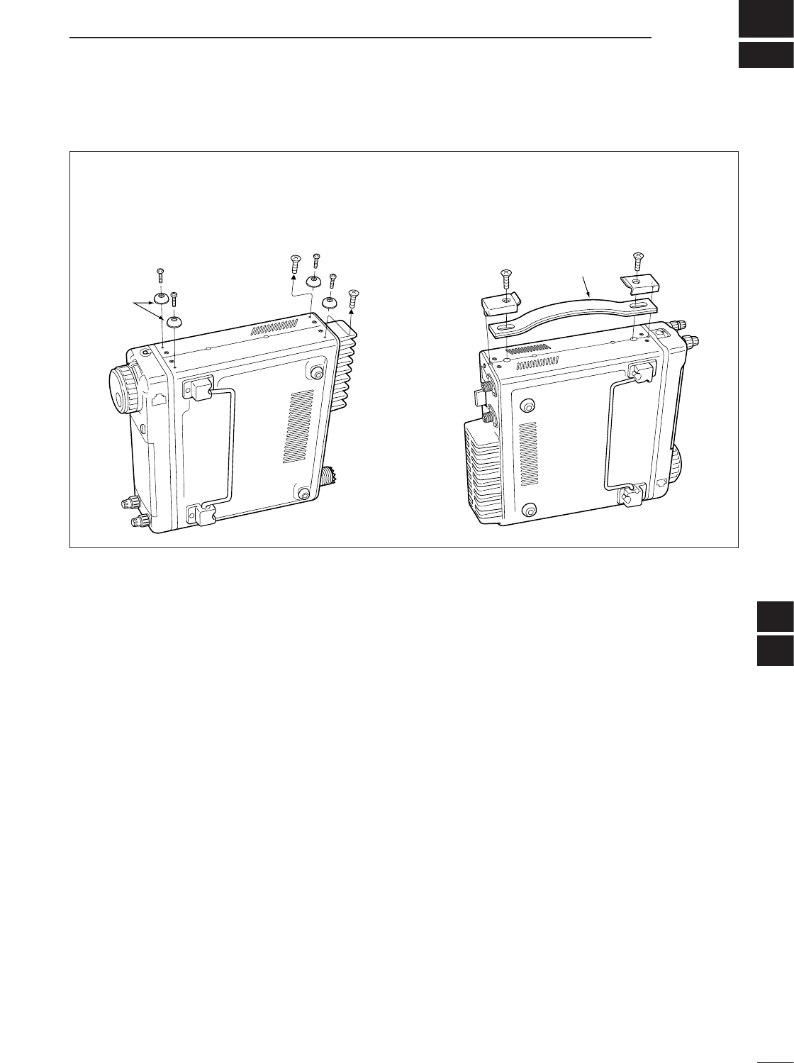
16
142
OPTION UNITS SETTING
15
16
■MB-106
CARRYING HANDLE
The optional MB-106
CARRYING HANDLE
is convenient
when carrying the transceiver for DX’ peditions, field
operation, etc.
qTighten the supplied screws plus rubber feet as
shown below.
wAttach the MB-106 to the left side of the transceiver
as shown below.
Carrying
handle
Rubber
feet
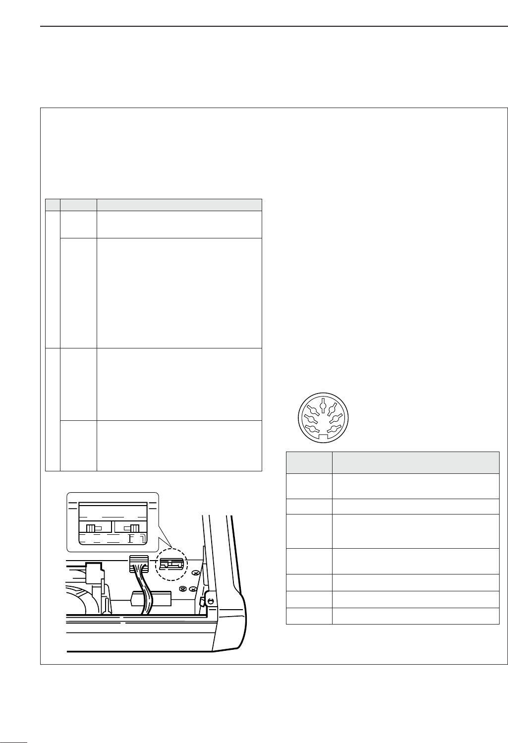
143
16 OPTION UNITS SETTING
■AT-180 internal switch description
The optional AT-180 has 3 operating conditions for HF
band operation. Select a suitable condition according
to your antenna system.
qRemove the top cover of the AT-180.
wSet the tuner switches to the desired positions ac-
cording to the table below.
•AT-180 inside top cover
•Specifications for the AT-180
• Frequency coverage : 1.9–54 MHz
• Input impedance : 50
•Maximum input : 120 W
power
•Minimum tuning : 8 W
power
•Matching impedance : 16.7–150 (HF band)
range 20–125 (50 MHz band)
• Tuning accuracy : Less than SWR 1.5:1
• Insertion loss : Less than 1.0 dB
(after tuning)
•Power supply : 13.8 V DC/1 A (supplied from
requirements the transceiver’s ACC socket)
• Dimensions (mm/in) : 167(W) ×58.6(H) ×225(D)
69⁄16(W) ×25⁄17(H) ×87⁄8(D)
• Weight : 2.4 kg; 5 lb 4 oz
• Supplied accessories : coaxial cable (1 m),
ACC cable (DIN 13 pins)
•Connector information for ACC(2) socket
ACC 2
1
2
3
4
76
5
S2 S1
DC BA
PIN NO./
NAME DESCRIPTION
q8 V Regulated 8 V output.
(10 mA max.)
wGND Connects to ground.
eSEND
Input/output pin.
Goes to ground when transmitting (20 mA
max). When grounded, transmits.
rBAND Band voltage output.
(Varies with amateur band; 0 to 8.0 V).
tALC ALC output voltage (–4 to 0 V).
yNC No connection.
u13.8V
13.8 V output when power is ON (1 A max).
SW Position
Operation
S1
A
(default)
The tuner operating condition is set by S2
described below.
B
THROUGH INHIBIT
The tuner tunes the antenna even when the
antenna has poor SWR (up to VSWR 3:1
after tuning). In this case, manual tuning is
necessary each time you change the fre-
quency although the tuner automatically
starts tuning when the VSWR is higher than
3:1. This setting is called “through inhibit,”
however, the tuner is set to “through” if the
VSWR is higher than 3:1 after tuning.
S2
C
TUNER SENSITIVE CONDITION
The tuner tunes each time you transmit (ex-
cept SSB mode). Therefore, the lowest
SWR is obtained at any given time.
For SSB mode, the same condition as the
“D” position.
D
(default)
NORMAL CONDITION
The tuner tunes when the SWR is higher
than 1.5:1. Therefore, the tuner activates
only when tuning is necessary.
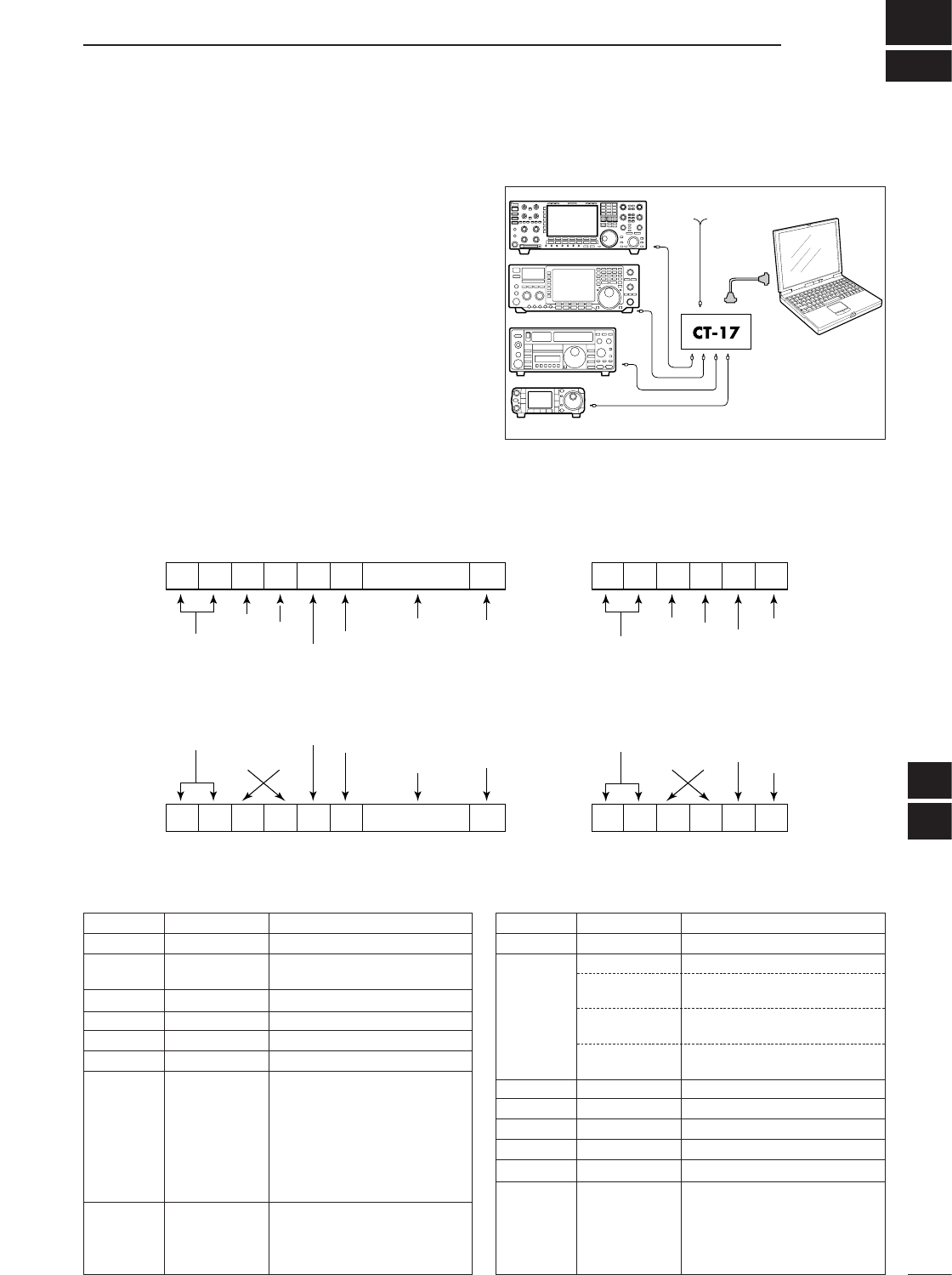
17
144
CONTROL COMMAND
CONTROLLER TO IC-7000
FE FE 70 E0 Cn Sc Data area FD
Preamble code (fixed)
Transceiver’s default address
Controller’s default address
Command number
(see table below)
Sub command number
(see table below)
BCD code data for frequency
or memory number entry
End of message code (fixed)
OK MESSAGE TO CONTROLLER
FE FE 70 E0 FB FD
Preamble code (fixed)
Transceiver’s default address
Controller’s default address
OK code
(fixed)
End of message code (fixed)
NG MESSAGE TO CONTROLLER
FE FE 70 E0 FA FD
NG code
(fixed)
IC-7000 TO CONTROLLER
FE FE E0 70 Cn Sc Data area FD
DCI-V connection example
The transceiver can be connected through an optional
CT-17
CI
-
V LEVEL CONVERTER
to a personal computer
equipped with an RS-232C port. The Icom Communi-
cation interface-V (CI-V) controls the following func-
tions of the transceiver.
Up to four Icom CI-V transceivers or receivers can be
connected to a personal computer equipped with an
RS-232C port. See p. 82 for setting the CI-V condition
using initial set mode.
DData format
The CI-V system can be operated using the following
data formats. Data formats differ according to com-
mand numbers. A data area is added for some com-
mands.
Personal
computer
mini-plug cable
IC-7000
9–15 V DC
■Remote jack (CI-V) information
16
17
DC
ommand table
00 — Send frequency data
01 Same as Send mode data
command 06
02 — Read band edge frequencies
03 — Read operating frequency
04 — Read operating mode
05 — Set operating frequency
06 00 Select LSB
01 Select USB
02 Select AM
03 Select CW
04 Select RTTY
05 Select FM
07 Select CW-R
08 Select RTTY-R
07 — Select VFO mode
00 Select VFO A
01 Select VFO B
A0 Equalize VFO A and VFO B
07 B0 Exchange VFO A and VFO B
08 — Select memory mode
0001–0105* Select memory channel
*P1=0100, P2=0101
0106, 0107 Select the call channel
(C1=0106, C2=0107)
A0 Set the bank number
(1=A, 2=B, 3=C, 4=D, 5=E)
09 — Memory write
0A — Memory to VFO
0B — Memory clear
0C — Read offset frequency
0D — Set offset frequency
0E 00 Scan stop
01 Programmed/memory scan start
02 Programmed scan start
22 Memory scan start
23 Select memory scan start
Command Sub command Description Command Sub command Description

• Command table (continued)
0E B0 Set as non-select channel
B1 Set as select channel
D0 Set scan resume OFF
D3 Set scan resume ON
0F 00 Turn the split function OFF
01 Turn the split function ON
10 Select simplex operation
11 Select –DUP operation
12 Select +DUP operation
10 00 AM/FM/WFM modes:
Select 10 Hz (1 Hz) tuning step
SSB/CW/RTTY modes: TS OFF
01 Select 100 Hz tuning step
02 Select 1 kHz tuning step
03 Select 5 kHz tuning step
04 Select 9 kHz tuning step
05 Select 10 kHz tuning step
06 Select 12.5 kHz tuning step
07 Select 20 kHz tuning step
08 Select 25 kHz tuning step
09 Select 100 kHz tuning step
10 AM/FM/WFM modes:
Select MHz step
SSB/CW/RTTY modes: TS OFF
11 — Select/read attenuator (0=OFF,
12=ON (12 dB))
13 00 Announce with voice synthesizer
01 (00=all data; 01=frequency and
02 S-meter level; 02=receive mode)
14 01 + Level data [AF] level setting (0=max. CCW to
255=max. CW)
02 + Level data [RF] level setting (0=max. CCW to
255=11 o’clock)
03 + Level data [SQL] level setting (0=11 o’clock to
255=max. CW)
06 + Level data NR level setting (0=min. to
255=max.)
07 + Level data Inside [PBT] setting or IF shift
setting (0=max. CCW, 128=cen-
ter, 255=max. CW)
08 + Level data Outside [PBT] setting
(0=max. CCW, 128=center,
255=max. CW)
09 + Level data CW Pitch setting (0=300 Hz,
128=600 Hz, 255=900 Hz, in 5 Hz
steps)
0A + Level data RF Power setting (0=mini. to
255=max.)
0B + Level data MIC Gain setting (0=mini. to
255=max.)
0C + Level data Key Speed setting (0=slow to
255=fast)
0D + Level data NOTCH (NF1) frequency setting
(0=low freq. to 255=high freq.)
0E + Level data COMP Level setting (0=0 to
10=10)
0F + Level data Break-IN DELAY setting (20=2.0d
to 130=13.0d)
12 + Level data NB level setting (0=0 to
255=100%)
15 + Level data Monitor gain setting (0=0 to
255=100%)
16 + Level data VOX gain setting (0=0 to
255=100%)
14 17 + Level data Anti-VOX gain setting (0=0 to
255=100%)
18 + Level data Contrast (LCD) setting (0=0 to
255=100%)
19 + Level data Bright (LCD) setting (0=0 to
255=100%)
1A + Level data NOTCH (NF2) frequency setting
(0=low freq. to 255=high freq.)
15 01 Read squelch condition
02 Read S-meter level
11 Read RF power meter
12 Read SWR meter
13 Read ALC meter
14 Read COMP meter
16 02 Preamp (0=OFF; 1=ON)
12 AGC selection (0=OFF; 1=Slow;
2=Mid; 3=Fast)
22 Noise blanker (0=OFF; 1=ON)
40 Noise reduction (0=OFF; 1=ON)
41 Auto notch (0=OFF; 1=ON)
42 Repeater tone (0=OFF; 1=ON)
43 Tone squelch (0=OFF; 1=ON)
44
Speech compressor (0=OFF; 1=ON)
45 Monitor (0=OFF; 1=ON)
46 VOX function (0=OFF; 1=ON)
47 Break-in (0=OFF; 1=semi break-
in; 2=full break-in)
48
Manual notch (NF1) (0=OFF; 1=ON)
4B DTCS (0=OFF; 1=ON)
4C VSC (0=OFF; 1=ON)
4F Twin Peak Filter (0=OFF; 1=ON)
50 Dial lock function (0=OFF, 1=ON)
51
Manual notch (NF2) (0=OFF, 1=ON)
19 00 Read the transceiver ID
1A 00 Send/read memory contents (see
p. 148 for details)
01 Send/read band stacking register
contents (see p. 148 for details)
02 Send/read memory keyer contents
(see p. 148 for details)
03 Send/read the selected filter width
(SSB, CW, RTTY: 0=50 Hz to
31=2700 Hz; AM: 0=200 Hz to
49=10 kHz)
04 Send/read the selected AGC time
constant (0=OFF, 1=0.1/0.3 sec. to
13=6.0/8.0 sec.)
050001 RF Power setting (0=mini. to
255=max.)
050002 MIC Gain setting (0=mini. to
255=max.)
050003 Send/read of SSB TX bandwidth
(lower edge) for wide
(0=100, 1=200, 2=300, 3=500 HZ)
050004 Send/read of SSB TX bandwidth
(higher edge) for wide (0=2500,
1=2700, 2=2800, 3=2900 HZ)
050005 Send/read of SSB TX bandwidth
(lower edge) for middle
(0=100, 1=200, 2=300, 3=500 HZ)
050006 Send/read of SSB TX bandwidth
(higher edge) for middle (0=2500,
1=2700, 2=2800, 3=2900 HZ)
Command Sub command Description Command Sub command Description
145
17 CONTROL COMMAND
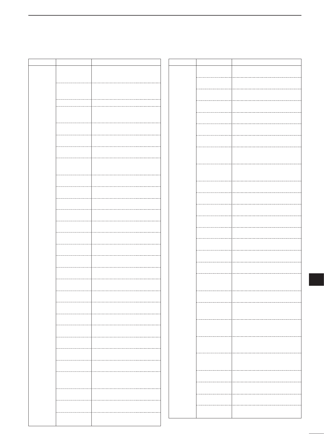
146
17
CONTROL COMMAND
17
CW: Clockwise, CCW: Counter Clockwise
• Command table (continued)
1A 050036 Send/read opening message
(0=OFF, 1=ON)
050037 Send/read my call sign setting (10
character: see p. 149 )
050038 Send/read power ON check
(0=OFF, 1=ON)
050039 Send/read current year (2000 to
2099)
050040 Send/read current date (0101 to
1231=Jan. 1st to Dec. 31st)
050041 Send/read current time (0000 to
2359=00:00 to 23:59)
050042 Send/read clock2 function (0=OFF,
1=ON)
050043 Send/read offset time for clock2
function (24001 to 24000=–24:00
to +24:00)
050044 Send/read auto power OFF period
(0=OFF, 1=30 min., 2=60 min.,
3=90 min.)
050045 Send/read TX monitor set
(0=OFF, 1=ON)
050046 Send/read TX monitor gain
(0=0% to 255=100%)
050047 Send/read confirmation beep
(0=OFF, 1=ON)
050048 Send/read band edge beep
(0=OFF, 1=ON)
050049 Send/read beep gain (0=min. to
255=max.)
050050 Send/read beep gain limit (0=OFF,
1=ON)
050051 Send/read RF/SQL control set
(0=Auto, 1=SQL, 2=RF+SQL)
050052 Send/read quick split set (0=OFF,
1=ON)
050053 Send/read split offset –9.999 to
+9.999 MHz (see p. 149 for de-
tails)
050054 Send/read split lock set (0=OFF,
1=ON)
050055 Send/read duplex offset 0.000 to
9.999 MHz for HF (see p. 149 for
details)
050056 Send/read duplex offset 0.000 to
9.999 MHz for 50 MHz band (see
p. 149 for details)
050057 Send/read duplex offset 0.000 to
9.999 MHz for 144 MHz band
(see p. 149 for details)
050058 Send/read duplex offset 0.000 to
9.999 MHz for 430 MHz band
(see p. 149 for details)
050059 Send/read one touch repeater set
(0=DUP–, 1=DUP+)
050060 Send/read auto repeater set
(0=OFF, 1=ON-1, 2=ON-2)
050061 Send/read tuner auto start set
(0=OFF, 1=ON)
050062 Send/read PTT tune set (0=OFF,
1=ON)
1A 050007 Send/read of SSB TX bandwidth
(lower edge) for narrow
(0=100, 1=200, 2=300, 3=500 HZ)
050008 Send/read of SSB TX bandwidth
(higher edge) for narrow (0=2500,
1=2700, 2=2800, 3=2900 HZ)
050009 Twin Peak Filter (0=OFF; 1=ON)
050010 Send/read RTTY mark frequency
(0=1275 Hz, 1=1615 Hz,
2=2125 Hz)
050011 Send/read RTTY shift width
(0=170 Hz, 1=200 Hz, 2=425 Hz)
050012 Send/read RTTY keying polarity
(0=Normal, 1=Reverse)
050013 Send/read CW key speed (0=0.6
WPM to 255=60 WPM)
050014 Send/read CW Pitch setting
(0=300 Hz, 120=900 Hz, in 5 Hz
steps)
050015 Send/read CW side tone level
(0=min. to 255=max.)
050016 Send/read CW side tone level limit
(0=OFF, 1=ON)
050017 Send/read LCD contrast (0=0% to
255=100%)
050018 Send/read LCD bright (0=0%,
255=100%)
050019 Send/read LCD unit bright (0=0%
to 255=100%)
050020 Send/read LCD flicker level (0=0%
to 255=100%)
050021 Send/read switch backlight (0=0%
to 255=100%)
050022 Send/read display type (0=A, 1=B,
2=C)
050023 Send/read display font type
(0=Basic, 1=Italic)
050024 Send/read display font size
(0=Normal, 1=Large)
050025 Send/read meter peak hold
(0=OFF, 1=ON)
050026 Send/read filter pop up indication
for PBT shifting (0=OFF, 1=ON)
050027 Send/read filter pop up indication
for IF filter setting (0=OFF, 1=ON)
050028 Send/read pop up indication for 1
Hz mode (0=OFF, 1=ON)
050029 Send/read pop up indication for
scope center/fix (0=OFF, 1=ON)
050030 Send/read TV pop up indication for
channel Up/Down (0=OFF, 1=ON)
050031 Send/read TV pop up indication for
P.AMP/ATT (0=OFF, 1=ON)
050032 Send/read indication of the voice
TX memory channel names
(0=OFF, 1=ON)
050033 Send/read indication of the keyer
memory names (0=OFF, 1=ON)
050034 Send/read indication of the DTMF
memory names (0=OFF, 1=ON)
050035 Send/read external display setting
(0=1:1.8, 1=1:1.6)
Command Sub command Description Command Sub command Description

147
17 CONTROL COMMAND
• Command table (continued)
1A 050087 Send/read FM mode selectability
(0=OFF: inhibition, 1=ON: selec-
table)
050088 Send/read WFM mode selectabil-
ity (0=OFF: inhibition, 1=ON: se-
lectable)
050089 Send/read external keypad set
for voice memory (0=OFF, 1=ON)
050090 Send/read external keypad set
for keyer memory (0=OFF, 1=ON)
050091 Send/read external keypad type
connected to [MIC] connector of
controller (0=Dot/Dash type,
1=Ext Keypad)
050092 Send/read CI-V transceive set
(0=OFF, 1=ON)
050093 Send/read reference frequency
set (0=0 to 255=100%)
050094 Send/read speech compresser
level (0=0 to 10=10)
050095 Send/read auto voice monitor set
(0=OFF, 1=ON)
050096 Send/read MIC memo function
(0=OFF, 1=ON)
050097 Send/read contest number style
(0=Normal, 1=190AANO,
2=190AANT, 3=90ANO,
4=90ANT)
050098 Send/read count up trigger chan-
nel (1=M1, 2=M2, 3=M3, 4=M4)
050099 Send/read present number
(1–9999)
050100 Send/read CW keyer repeat time
(1=1 sec. to 60=60 sec.)
050101 Send/read CW keyer dot/dash
ratio (28=1:1:2.8 to 45=1:1:4.5)
050102 Send/read rise time (0=2 msec.,
1=4 msec., 2=6 msec.,
3=8 msec.)
050103 Send/read CW paddle polarity
(0=Normal, 1=Reverse)
050104 Send/read CW keyer type
(0=Straight, 1=Bug-key, 2=ELEC-
Key)
050105 Send/read MIC up/down keyer
(HM-103) set (0=OFF, 1=ON)
050106 Send/read RTTY decode USOS
(0=OFF, 1=ON)
050107 Send/read RTTY decode new line
code (0=CR,LF,CR+LF, 1=CR+LF)
050108 Send/read scope max. hold
(0=OFF, 1=ON)
050109 Send/read scope size set (0=Nor-
mal, 1=Wide)
050110 Send/read fast sweep set
(0=1 sweep, 1=Continuous)
050111 Send/read fast sweep audio level
(0=0 dB, 1=–10 dB, 2=OFF)
050112 Send/read NB level set
(0=min. to 255=max.)
050113 Send/read NB width set
(0=min. to 255=max.)
1A 050063 Send/read [TUNER/CALL] key ac-
tion set (0=Manual, 1=Auto)
050064 Send/read [ACC] (pin 7) output
“VSEND” set (0=OFF, 1=UHF
only, 2=ON)
050065 Send/read speech level (0=0 to
255=100%)
050066 Send/read speech language
(0=English, 1=Japanese)
050067 Send/read speech speed (0=Slow,
1=Fast)
050068 Send/read S-level speech
(0=OFF, 1=ON)
050069 Send/read speech capability with
[MODE] key operation
(0=OFF, 1=ON)
050070 Send/read memopad numbers
(0=5 ch, 1=10 ch)
050071 Send/read scan speed
(0=Low, 1=High)
050072 Send/read scan resume
(0=OFF, 1=ON)
050073 Send/read main dial auto TS
(0=OFF, 1=Low, 2=High)
050074 Send/read [F-1] key assigment of
the HM-151. (0=“P.AMP/ATT,”
1=“NB,” 2=“NR,” 3=“MNF,”
4=“ANF,” 5=“TS,” 6=“SPL,”
7=“A/B,” 8=“MCL,” 9=“BNK,”
10=“COM,” 11=“AGC,” 12=“TBW,”
13=“DUP,” 14=“TON,” 15=“MET,”
16=“VSC,” 17=“MPW,” 18=“MPR,”
19=“<SCOPE>,” 20=“<METER>”)
050075 Send/read [F-2] key assigment of
the HM-151. (Selectable functions
are same as [F-1].)
050076 Send/read mic. up/down speed
(0=Low, 1=High)
050077 Send/read quick RIT/∂TX clear
function (0=OFF, 1=ON)
050078 Send/read SSB/CW synchronous
tuning function (0=OFF, 1=ON)
050079 Send/read CW normal side set
(0=LSB, 1=USB)
050080 Send/read voice recorder 1st
menu set (0=Voice-root, 1=Voice-
RX/TX)
050081 Send/read keyer 1st menu set
(0=Keyer-root, 1=Keyer-send)
050082 Send/read DTMF 1st menu set
(0=DTMF-root, 1=DTMF-send)
050083 Send/read SSB mode selectability
(0=OFF: inhibition, 1=ON: selec-
table)
050084 Send/read CW mode selectability
(0=OFF: inhibition, 1=ON: selec-
table)
050085 Send/read RTTY mode selectabil-
ity. (0=OFF: inhibition, 1=ON: se-
lectable)
050086 Send/read AM mode selectability
(0=OFF: inhibition, 1=ON: selec-
table)
Command Sub command Description Command Sub command Description
148
17
CONTROL COMMAND
17
• Command table (continued) DTo send/read memory contents
When sending or reading memory contents, additional code
as follows must be added to appoint the memory channel.
➥Additional code: 0000–0102 (0100=P1, 0101=P2, 0102=Call)
DBand stacking register
To send or read the desired band stacking register’s con-
tents, combined code of the frequency band and register
codes as follows are used.
For example, when sending/reading the oldest contents in
the 21 MHz band, the code “0703” is used.
• Frequency band code
• Register code
DCodes for memory keyer contents
To send or read the desired memory keyer contents, the
channel and character codes as follows are used.
• Channel code
• Character’s code
1A 050114 Send/read NR level set
(0=0 to 15=15)
050115 Send/read VOX gain (0=0% to
255=100%)
050116 Send/read anti VOX gain (0=0% to
255=100%)
050117 Send/read VOX delay (0=0.0 sec.
to 20=2.0 sec.)
050118 Send/read DTMF speed set
(0=100 msec., 1=200 msec.,
2=300 msec., 3=500 msec.)
050119 Send/read Break-IN delay set
(20=2.0d to 130=13.0d)
06 Send/read SSB transmit band-
width (0=WIDE, 1=MID, 2=NAR)
07 Send/read DSP filter shape
(0= sharp, 1= soft)
08 Send/read manual notch filter1
bandwidth
(0=WIDE, 1=MID, 2=NAR)
09 Send/read manual notch filter2
bandwidth
(0=WIDE, 1=MID, 2=NAR)
0A Send/read 9600 bps mode set
(0=OFF, 1=ON)
1B 00 Set/read repeater tone frequency
(see p. 149 for details)
01 Set/read TSQL tone frequency
(see p. 149 for details)
02 Set/read DTCS code and polarity
(see p. 149 for details)
1C 00 Set/read the transceiver’s condi-
tion (0=Rx; 1=Tx)
01 Set/read antenna tuner condition
(0=OFF, 1=ON, 2=Start tuning or
while tuning)
Command Sub command Description
Code Frequency band Frequency range (unit: MHz)
01 1.8 1.800000– 1.999999
02 3.5 3.400000– 4.099999
03 7 6.900000– 7.499999
04 10 9.900000–10.499999
05 14 13.900000–14.499999
06 18 17.900000–18.499999
07 21 20.900000–21.499999
08 24 24.400000–25.099999
09 28 28.000000–29.999999
10 50 50.000000–54.000000
11 144 144.000000–148.000000
12 430 430.000000–450.000000
13 GENE Other than above
Code Registered number
01 1 (latest)
02 2
03 3 (oldest)
Code Channel number
01 M1
02 M2
03 M3
04 M4
CW: Clockwise, CCW: Counter Clockwise
Character ASCII code Description
0–9 30–39 Numerals
A–Z 41–5A Alphabetical characters
space 20 Word space
/ 2F Symbol
? 3F Symbol
, 2C Symbol
. 2E Symbol
^ 5E e.g., to send
BT
, enter ^4254
✱2A Inserts contact number (can be
used for 1 channel only)
149
17 CONTROL COMMAND
DCharacter’s code for my call
DCodes for memory name contents
To send or read the desired memory name settings, the char-
acter codes, instructed codes for memory keyer contents as
above, and follows are additionally used.
•Character’s code— Alphabetical characters
•Character’s code— Symbols
DSplit/Duplex frequency setting
The following data sequence is used when sending/reading
the split or duplex frequency setting.
DRepeater tone/tone squelch frequency
setting
The following data sequence is used when sending/reading
the DTCS code and polarity setting.
DDTCS code and polarity setting
The following data sequence is used when sending/reading
the DTCS code and polarity setting.
Fixed digit: 0
1st digit: 0–7
2nd digit: 0–7
3rd digit: 0–7
Transmit polarity:
0= Normal
1= Reverse
Receive polarity:
0= Normal
1= Reverse
q
XX0XX
we
X
100Hz digit: 0–2
10 Hz digit: 0–9
1 Hz digit: 0–9
0.1 Hz digit: 0–9
Fixed digit: 0*
Fixed digit: 0*
q*
00XXX
we
X
*Not necessary when setting a frequency.
1 kHz digit: 0—9
100 Hz digit: 0 (fixed)
100 kHz digit: 0—9
10 kHz digit: 0—9
10 MHz digit: 0 (fixed)
1 MHz digit: 0—4
Direction:
00=+ direction
01=— direction
q
0XXXXXX
we
0
r*
*No need to enter for duplex frequency setting.
Character ASCII code Character ASCII code
a–z 61–7A — —
Character ASCII code Character ASCII code
!21#23
$24%25
&26¥5C
?3F ” 22
’27`60
+2B–2D
:3A;3B
=3D<3C
>3E ( 28
)29[5B
]5D{7B
}7D|7C
_5F–7E
@40
Character ASCII code Description
0–9 30–39 Numerals
A–Z 41–5A Alphabetical characters
space 20 Word space
– 2D Symbol
. 2E Symbol
/ 2F Symbol
18
150
SPECIFICATIONS
■General
• Frequency coverage :
Receive
30 kHz–199.999999 MHz*1*2
400–470.000000 MHz*1*2
Transmit
1.800–1.999999 MHz*2, 3.500–3.999999 MHz*2
5.33050*3, 5.34650*3, 5.36650*3,
5.37150*3, 5.40350*3,
7.000–7.300 MHz*2, 10.100–10.150 MHz*2,
14.000–14.350 MHz*2, 18.068–18.168 MHz*2,
21.000–21.450 MHz*2, 24.890–24.990 MHz*2,
28.000–29.700 MHz*2, 50.000–54.000 MHz*2,
144.000–148.000 MHz*2, 430.000 –450.000 MHz*2
*1Some frequency bands are not guaranteed.
*2Depending on version. *3USA version only.
• Mode : SSB, CW, RTTY, AM, FM, WFM
(WFM is for receive only)
•
Number of memory CH
: 503 (split memory: 99×5 banks; scan
edges: 6; call channel: 2 ) channels
• Antenna connector : SO-239×2(for HF/50 MHz and
144/430 MHz) /50
•Usable temperature : –10°C to +60°C (+14°F to +140°F)
range
• Frequency stability : Less than ± 0.5 ppm
(0°C to +50°C; +32°F to +122°F)
•Power supply : 13.8 V DC±15% (negative ground)
requirement
•Current drain : Transmit (at 100 W) 22 A
(at 13.8 V DC) Receive squelched 1.3 A
max. audio 1.6 A
• Dimensions : 167(W) ×58(H) ×180(D) mm,
(projections not included) 69⁄16(W) ×29⁄32(H) ×73⁄32(D) in
• Weight (approx.) : 2.3 kg (5 lb 1 oz)
• CI-V connector : 2-conductor 3.5 (d) mm (1⁄8˝)
• Video connector : 2-conductor 3.5 (d) mm (1⁄8˝)
• ACC connector : 13-pin
• Data connector : 6-pin
■Transmitter
• Output power :
SSB, CW, FM, RTTY 2–100 W (1.8–50 MHz bands)
2–50 W (144 MHz band)
2–35 W (430 MHz band)
AM 1–40 W (1.8–50 MHz bands)
2–20 W (144 MHz band)
2–14 W (430 MHz band)
• Modulation system :
SSB Balanced modulation
AM Low level modulation
FM Variable reactance modulation
•Spurious emissions : Less than –60 dB*
*spurious freq.: below 30 MHz: –50 dB; above 50 MHz: –60 dB
• Carrier suppression : More than 50 dB
• Unwanted sideband : More than 50 dB
•Microphone : 8-pin modular jack (600 )
connector
•KEY connector : 3-conductor 6.35 (d) mm (1⁄4˝)
• RTTY connector : 3-conductor 3.5 (d) mm (1⁄8˝)
■Receiver
• Receive system :
SSB/CW/RTTY/AM/FM
Triple-conversion superheterodyne
WFM Double-conversion superheterodyne
• Intermediate frequencies:
1st
SSB/CW/RTTY/AM/FM 124.487 MHz
WFM 134.732 MHz
TV (Video) 69.0100 MHz
2nd
SSB/CW/RTTY/AM/FM 455 kHz
WFM 10.700 MHz
3rd
SSB/CW/RTTY/AM/FM 16.15 kHz
• Sensitivity (at preamp ON):
• Squelch sensitivity (threshold; preamp ON) :
SSB/CW/RTTY/AM Less than 5.6 µV
FM Less than 0.3 µV
• Selectivity :
SSB* (BW=2.4 kHz) More than 2.4 kHz/–6 dB
Less than 3.6 kHz/–60 dB
CW* (BW=500 Hz) More than 500 Hz/–6 dB
Less than 900 Hz/–60 dB
RTTY (BW=350 Hz) More than 360 Hz/–6 dB
Less than 650 Hz/–60 dB
AM (BW=6 kHz) More than 6.0 kHz/–6 dB
Less than 15.0 kHz/–60 dB
FM (BW=15 kHz) More than 12.0 kHz/–6 dB
Less than 20.0 kHz/–60 dB
*IF filter shape is set to SHARP.
•Spurious and image rejection ratio:
HF bands More than 70 dB
50 MHz band More than 70 dB
(except IF/2 through)
144/430 MHz band More than 65 dB (except IF through)
• Audio output power : More than 2.0 W at 10% distortion
with an 8 load (at 13.8 V DC)
• RIT variable range : ±9.99 kHz
• PHONES connector : 3-conductor 3.5 (d) mm (1⁄8˝)/8
• EXT SP connector : 2-conductor 3.5 (d) mm (1⁄8˝)/8
17
18
Frequency
range
[MHz]
SSB/CW/
RTTY
10 dB S/N
AM
10 dB S/N
FM
12 dB SINAD
WFM
12 dB SINAD
0.5–1.8 —13 µV — —
1.8–28 0.15 µV 2.0 µV — —
28–29.995 0.5 µV —
50 MHz band 0.12 µV 1.0 µV 0.25 µV —
76–108 — — — 10.0 µV
144/430 MHz
bands 0.11 µV 1.0 µV 0.18 µV —
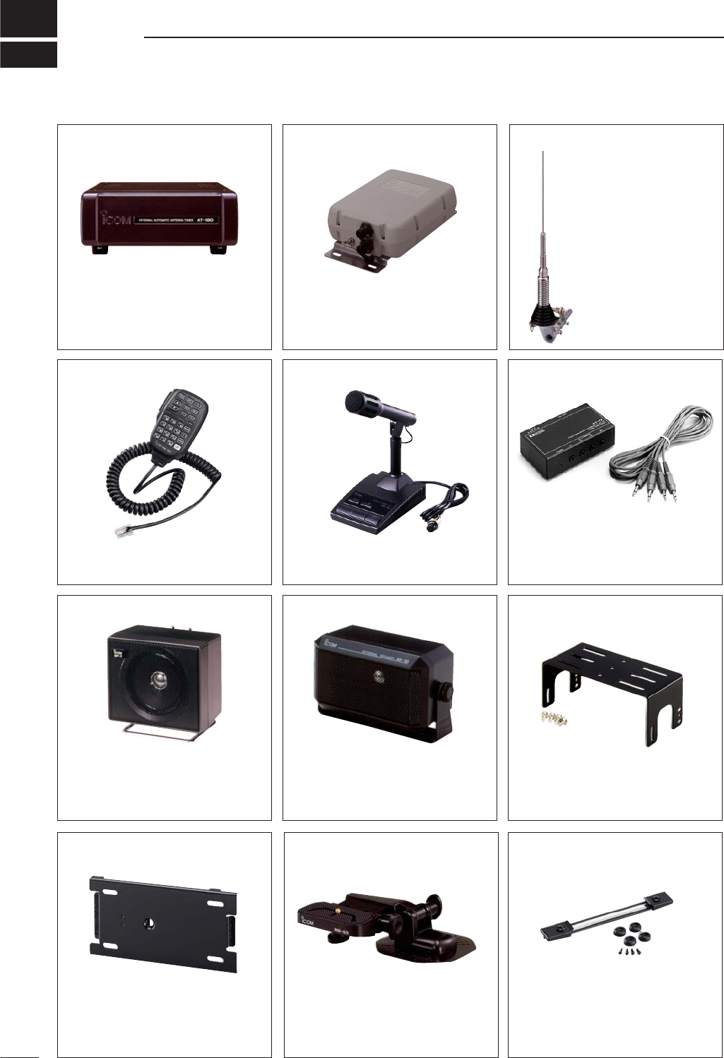
MB-105 MOUNTING BRACKET
Metal plate for attaching the front panel to a
wall or other such flat surface.
19
151
OPTIONS
AT-180 HF/50 MHz AUTOMATIC
ANTENNA TUNER
Fully automatic antenna tuner with preset
memories for each 100 kHz. Unique “auto-
matic tuner on” function is available. See
p. 89 for AT-180 specifications.
AH-4 HF AUTOMATIC ANTENNA
TUNER
Specially designed to tune a long wire an-
tenna for portable or mobile HF/50 MHz op-
eration. The “PTT tune” function provides
simple operation.
• Input power rating: 150 W
HM-151 HAND MICROPHONE
Standard hand microphone.
AH-2b ANTENNA ELEMENT
A 2.5 m long antenna ele-
ment for mobile operation
with the AH-4.
•Frequency coverage
7–54 MHz band with the
AH-4
SM-20 DESKTOP MICROPHONE
Includes [UP]/[DOWN] switches and a low
cut function. The OPC-589 is necessary to
use this microphone.
SP-7 EXTERNAL SPEAKER
Compact speaker for base station opera-
tion. Height can be adjusted for your conve-
nience.
• Input impedance: 8
• Max. input power: 5 W
CT-17 CI-V LEVEL CONVERTER
UNIT
For remote transceiver control using a per-
sonal computer equipped with an RS-232C
port. You can change frequencies, operat-
ing mode, memory channels, etc., via your
computer.
SP-10 EXTERNAL SPEAKER
External speakers suitable for mobile oper-
ation.
SP-12: Slim-type; 8 /3 W
SP-10: Compact-type; 4 /5 W
MB-62
MOBILE MOUNTING BRACKET
Mounts the transceiver main body, with or
without the front panel, inside a vehicle.
MB-65 MOUNTING BASE
Allows you to conveniently vehicle-mount
the front panel of the IC-7000. An MB-105
must be used in combination with the MB-
65.
MB-106 CARRYING HANDLE
Convenient when carrying the transceiver.
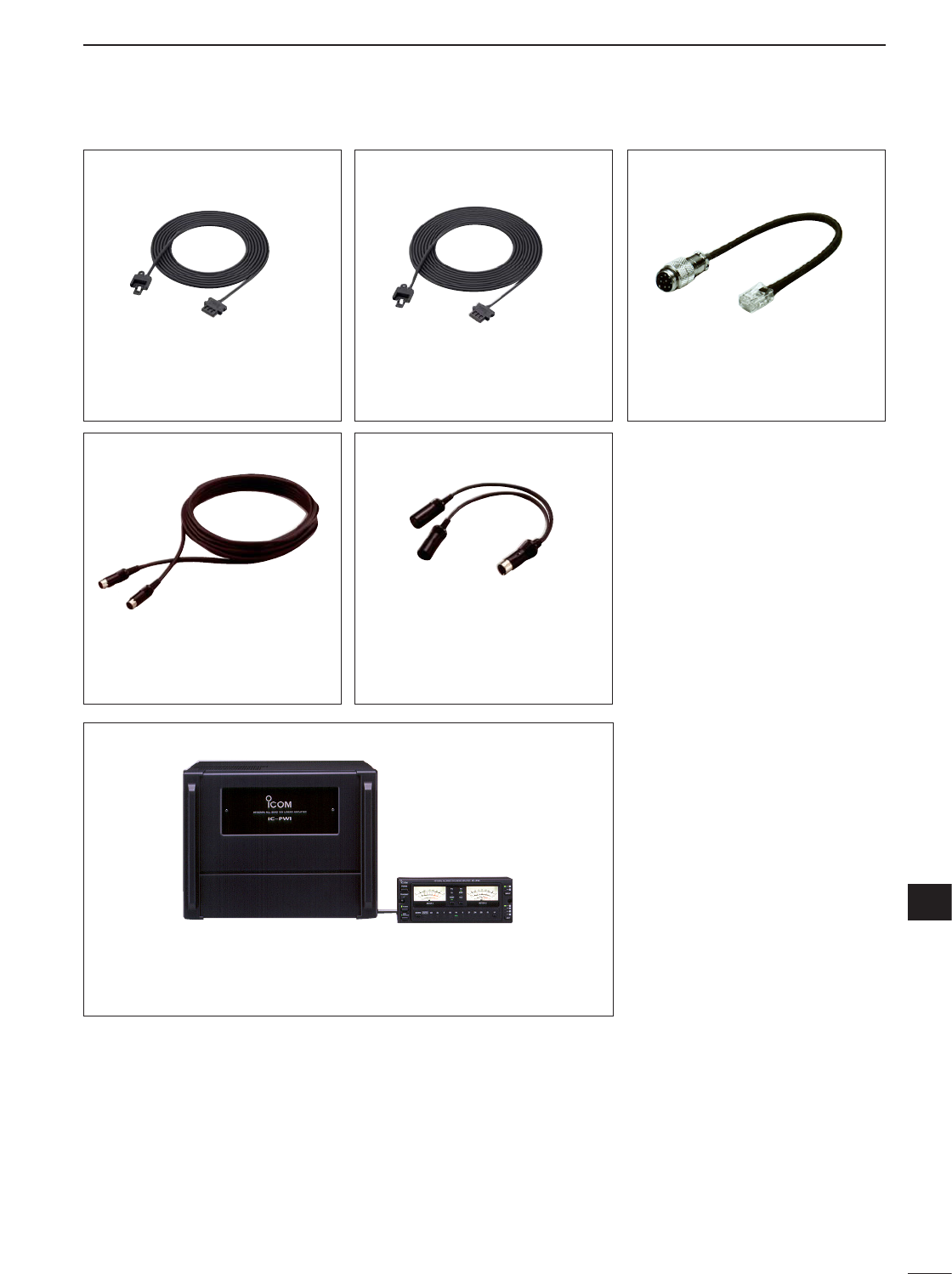
152
19
OPTIONS
19
OPC-598 ACC 13-PIN CABLE
Required when using the AT-180.
OPC-1443
SEPARATION CABLE
Provide front panel detached operation for
mobile installations or compact transceiver
operation.
• OPC-1443: 3.5 m (11.5 ft)
• OPC-1444: 5 m (16.4 ft)
OPC-1444
SEPARATION CABLE
Provide front panel detached operation for
mobile installations or compact transceiver
operation.
• OPC-1443: 3.5 m (11.5 ft)
• OPC-1444: 5 m (16.4 ft)
OPC-589
MICROPHONE ADAPTOR CABLE
Conversion between 8-pin modular and 8-
pin metal connector for using a desktop mi-
crophone with the IC-7000.
OPC-599 ADAPTOR CABLE
13-pin, ACC connector to 7-pin + 8-pin ACC
connector.
IC-PW1/EURO HF/50 MHz ALL BAND 1 kW LINEAR AMPLIFIER
Full-duty 1 kW linear amplifier including an automatic antenna tuner. Has
automatic tuning and band selection capability. Full break-in (QSK) oper-
ation is possible. The amplifier/power supply unit and the remote control
unit are separated.
OPC-742 ACC 13-PIN CABLE
Required when using both the AT-180
and 2 m liniar amplifier.
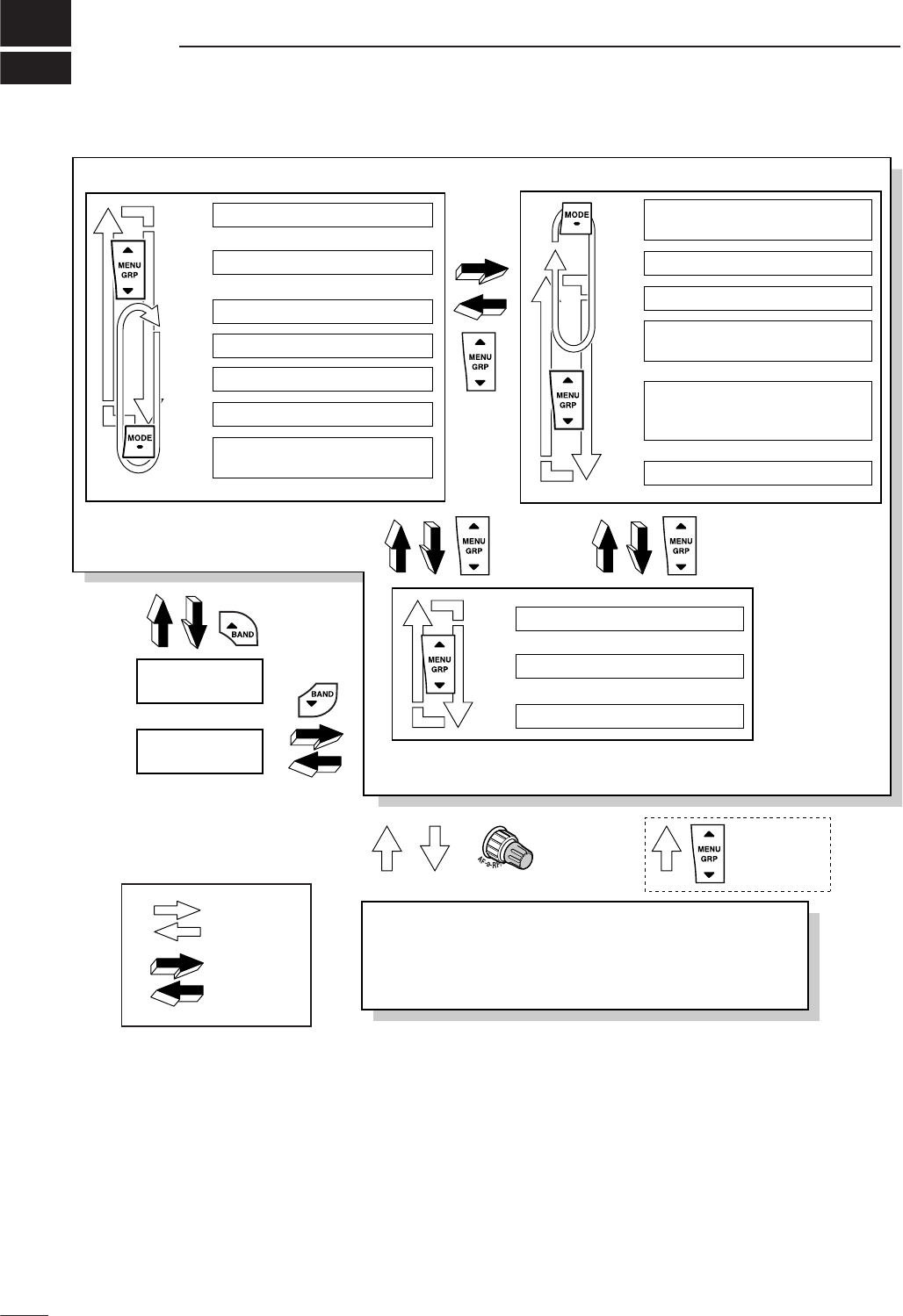
20
153
MENU GUIDE
Main menu group Sub menu group
Graphic menu group
M
-
1 SPL A/B FIL
M
-
2 MEM MW MCL
XFC
V/M
M
-
3 VOX COM AGC
VOXM
-
3 DUP TON
1/4
BRK
M
-
3 AGC
1/4M
-
3 AGC
(SSB)
(SSB/AM)
(CW)
(RTTY)
(in memory mode)
(CW)
(RTTY)
(FM/WFM)
(FM/WFM)
BAND scope
Multi function meter
SWR meter
VO MET VSC
S
-
1
VO KEY MET VSCS
-
1
VO DEC MET VSCS
-
1
VO DTM MET VSCS
-
1
SCN PRI
SEL
V/M VSC
S
-
2
MW MPW MPR
S
-
3
G
-
1
BAND
scope
G
-
2
Multi function
meter
G
-
3
VOXM
-
3 AGC
TBW
9600
(AM)
Push
[AF]
momentarily
Set mode menu
Push
momentarily
Push
for 1 sec.
Push
[Z(MENU/GRP)]
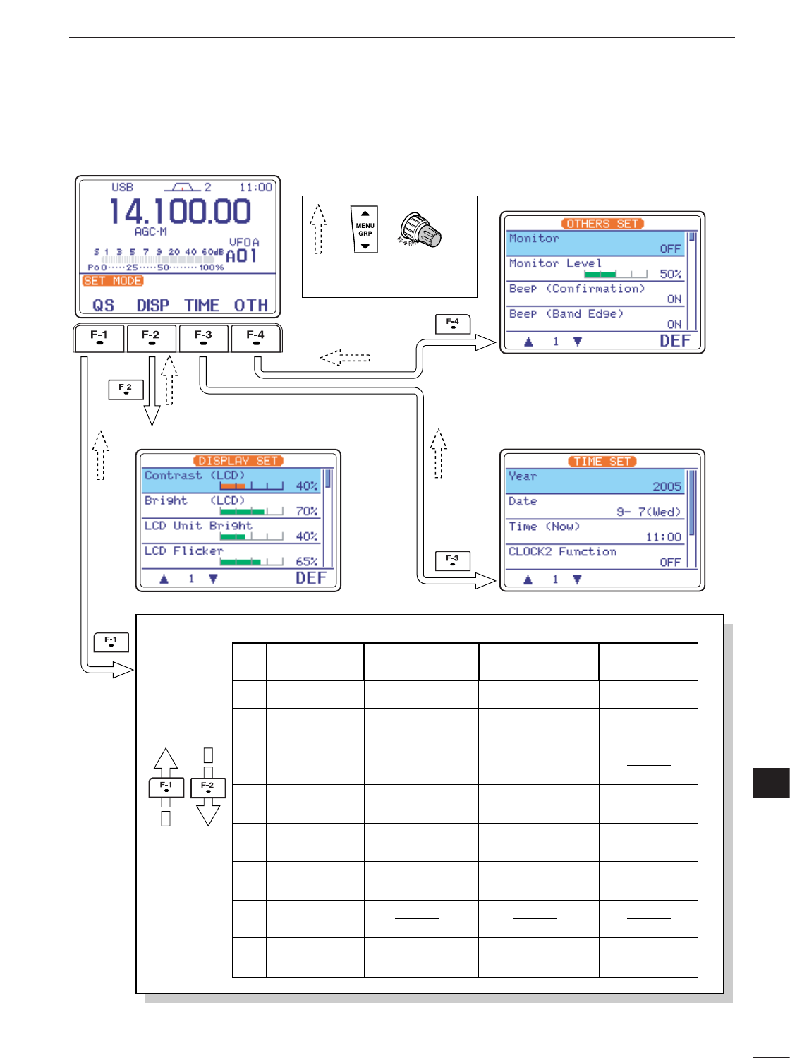
154
20
MENU GUIDE
20
• Set mode menu
• Display set mode • Time set mode
• Miscellaneous (others) set mode
Quick set mode
No.
1RF Power RF Power RF Power
2MIC Gain Key Speed Twin Peak
Filter
3
4
5
6
7
8
SSB TBW
(WIDE) L
SSB TBW
(WIDE) H
Side Tone
Level
SSB TBW
(MID) L
Side Tone
Level Limit
RTTY Mark
Frequency
RTTY Shift
Width
RTTY Keying
Polarity
SSB TBW
(MID) H
SSB TBW
(NAR) L
SSB TBW
(NAR) H
CW Pitch
SSB
mode
CW
mode
RTTY
mode
RF Power
MIC Gain
AM/FM
mode
Set mode description
Push [Z(MENU/GRP)] or [AF] switch
to return to upper menu

155
MEMO

156
MEMO

1-1-32 Kamiminami, Hirano-ku, Osaka 547-0003, Japan
A-6241H-1EX
Printed in Japan
© 2005 Icom Inc.
<Intended Country of Use>
■GER ■FRA ■ESP ■SWE
■AUT ■NED ■POR ■DEN
■GBR ■BEL ■ITA ■FIN
■IRL ■LUX ■GRE ■SUI
■NOR
IC-7000
#02, #12
(Europe)
HF+50 M
<Intended Country of Use>
■GER ■FRA ■ESP ■SWE
■AUT ■NED ■POR ■DEN
■GBR ■BEL ■ITA ■FIN
■IRL ■LUX ■GRE ■SUI
■NOR
IC-7000
#10, #20
(Italy)
HF only
<Intended Country of Use>
■GER ■FRA ■ESP ■SWE
■AUT ■NED ■POR ■DEN
■GBR ■BEL ■ITA ■FIN
■IRL ■LUX ■GRE ■SUI
■NOR
IC-7000
#13
(France)
HF+50 M