ICOM orporated 259000 Amateur HF Scanning Transceiver User Manual IC 7800 Eng
ICOM Incorporated Amateur HF Scanning Transceiver IC 7800 Eng
Contents
- 1. Users Manual Part 1
- 2. Users Manual Part 2
- 3. Users Manual Part 3
- 4. Users Manual Part 4
- 5. Users Manual Part 5
Users Manual Part 1
![iiPRECAUTIONSRWARNING HIGH VOLTAGE! NEVER at-tach an antenna or internal antenna connector duringtransmission. This may result in an electrical shock orburn.RWARNING! NEVER operate the transceiverwith a headset or other audio accessories at high vol-ume levels. Hearing experts advise against continuoushigh volume operation. If you experience a ringing inyour ears, reduce the volume or discontinue use.RCAUTION! NEVER change the internal set-tings of the transceiver. This result in reduced trans-ceiver performance and/or damage to the transceiver.RCAUTION! NEVER touch the transceiver topcover when transmitting continuously for long periods.It will become hot.In particular, incorrect settings for transmitter circuits,such as output power, idling current, etc., might dam-age the expensive final devices.The transceiver warranty does not cover any problemscaused by unauthorized internal adjustment.RCAUTION! The transceiver weighs approx. 25 kg(55 lb). 2 peoples should be present to carry, lift up orturn over the transceiver, etc. RCAUTION! The socket-outlet must be near thetransceiver and must be easily accessible.RACHTUNG! Die Steckdose muß nabe beidiesem Gerät angebracht und zugänglich sein.RNEVER let metal, wire or other objects touch anyinternal part or connectors on the rear panel of thetransceiver. This may result in an electric shock.RNEVER let objects impede the operation of thecooling fan on the rear panel.RNEVER expose the transceiver to rain, snow orany liquids.RNEVER installing the transceiver in a place with-out adequate ventilation. Heat dissipation may be af-fected, and the transceiver may be damaged.RNEVER operate or touch the transceiver with wethands. This may result in an electric shock or damagethe transceiver.DO NOTthe use of chemical agents such as benzineor alcohol when cleaning, as they can damage thetransceiver’s surfaces.DO NOT push the PTT when not actually desiring totransmit.AVOID using or placing the transceiver in areas withtemperatures below ±0°C (+32°F) or above +50°C(+122°F).AVOID placing the transceiver in excessively dusty en-vironments or in direct sunlight.AVOID placing the transceiver against walls or puttinganything on top of the transceiver. This will obstructheat dissipation.Place unit in a secure place to avoid inadvertent useby children.BE CAREFUL! The top panel will become hot whenoperating the transceiver continuously for long periods.BE CAREFUL! If a linear amplifier is connected, setthe transceiver’s RF output power to less than the lin-ear amplifier’s maximum input level, otherwise, the lin-ear amplifier will be damaged.Use Icom microphones only (supplied or optional).Other manufacturer’s microphones have different pinassignments, and connection to the IC-7800 may dam-age the transceiver.The LCD display may have cosmetic imperfections thatappear as small or dark spots. This is not a malfunctionor defect, but a normal characteristic of LCD displays.During maritime mobile operation, keep the transceiverand microphone as far away as possible from the mag-netic navigation compass to prevent erroneous indica-tions.Turn [I/O] switch (on the rear panel) OFF and/or dis-connect the AC power cable from the AC outlet whenyou will not use the transceiver for long period of time.For U.S.A. onlyCAUTION: Changes or modifications to this device,not expressly approved by Icom Inc., could void yourauthority to operate this device under FCC regulations.](https://usermanual.wiki/ICOM-orporated/259000.Users-Manual-Part-1/User-Guide-397407-Page-3.png)
![viDDSP filter shape …………………………………………………… 5-14DFilter shape set mode ……………………………………………… 5-14■Dualwatch operation ………………………………………………… 5-16■Noise blanker ………………………………………………………… 5-17DNB set mode ………………………………………………………… 5-17■Noise reduction ………………………………………………………… 5-18■Dial lock function ……………………………………………………… 5-18■Notch function ………………………………………………………… 5-19■Digital selector ………………………………………………………… 5-19Section 6 FUNCTIONS FOR TRANSMIT■VOX function …………………………………………………………… 6-2DUsing the VOX function …………………………………………… 6-2DAdjusting the VOX function ………………………………………… 6-2DVOX set mode ……………………………………………………… 6-2■Break-in function ………………………………………………………… 6-3DSemi break-in operation …………………………………………… 6-3DFull break-in operation ……………………………………………… 6-3■∂TX function …………………………………………………………… 6-4D∂TX monitor function ………………………………………………… 6-4■Monitor function ………………………………………………………… 6-4■Transmit filter width setting (SSB only) ……………………………… 6-5■Speech compressor (SSB only) ……………………………………… 6-5■Split frequency operation ……………………………………………… 6-6■Quick split function ……………………………………………………… 6-7DSplit lock function …………………………………………………… 6-7Section 7 VOICE RECORDER FUNCTIONS■About digital voice recorder …………………………………………… 7-2■Recording a received audio …………………………………………… 7-3DBasic recording ……………………………………………………… 7-3DOne-touch recording ………………………………………………… 7-3■Playing the recorded audio …………………………………………… 7-4DBasic playing ………………………………………………………… 7-4DOne-touch playing …………………………………………………… 7-4■Protect the recorded contents ………………………………………… 7-5■Erasing the recorded contents ………………………………………… 7-5■Recording a message for transmit …………………………………… 7-6DRecording …………………………………………………………… 7-6DConfirming a message for transmit ………………………………… 7-6■Programming a memory name ……………………………………… 7-7■Sending a recorded message ………………………………………… 7-8DTransmit level setting ……………………………………………… 7-8■Voice set mode ………………………………………………………… 7-9■Saving a voice memory into the CF card …………………………… 7-10DSaving the received audio memory ……………………………… 7-10DSaving the TX memory …………………………………………… 7-10Section 8 MEMORY OPERATION■Memory channels ……………………………………………………… 8-2■Memory channel selection …………………………………………… 8-2DUsing the [Y]/[Z] keys ……………………………………………… 8-2DUsing the keypad …………………………………………………… 8-2■Memory list screen ……………………………………………………… 8-3DSelecting a memory channel using the memory list screen …… 8-3DConfirming programmed memory channels ……………………… 8-3TABLE OF CONTENTS](https://usermanual.wiki/ICOM-orporated/259000.Users-Manual-Part-1/User-Guide-397407-Page-7.png)
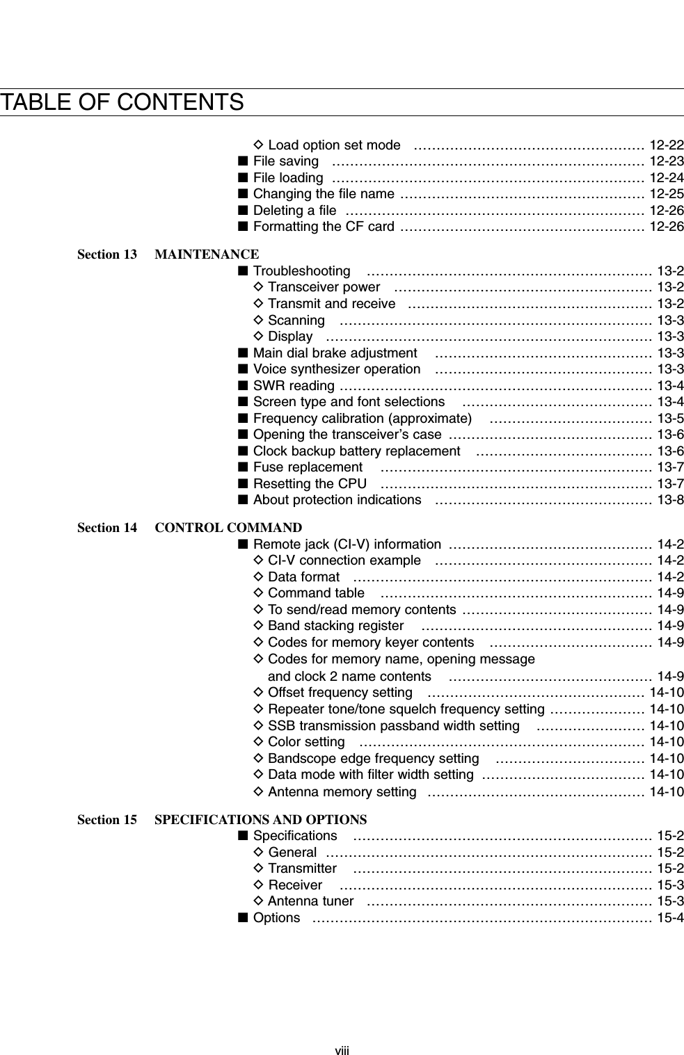
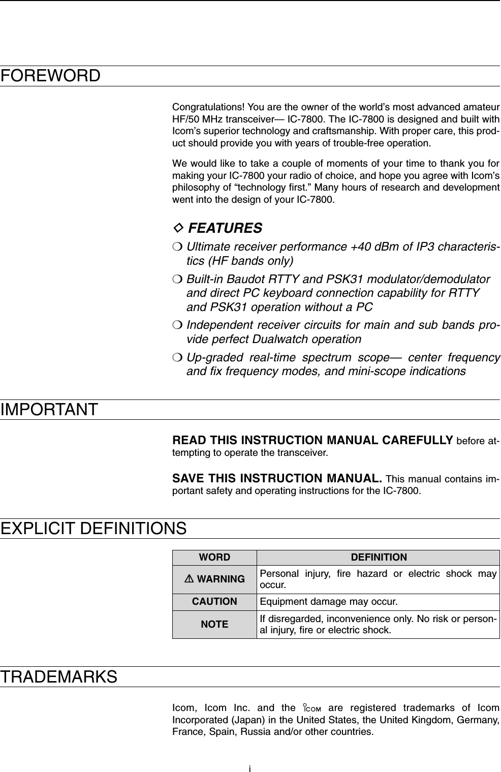
![1-2■Front panelqPOWER SWITCH [POWER] (p. 3-2)➥Push to turn the transceiver power ON.• The [POWER] indicator above this switch lights greenwhen powered ON.➥Push for 1 sec. to turn the transceiver powerOFF.• The [POWER] indicator lights orange even the trans-ceiver is powered OFF when the internal power sup-ply is switched ON.wTRANSMIT SWITCH [TRANSMIT]Selects transmitting or receiving.• The [TX] indicator lights red while transmitting and the[RX] indicator lights green when the squelch is open.eANTENNA TUNER SWITCH [TUNER] (p. 10-5)➥Turn the internal antenna tuner ON and OFF (by-pass) when pushed momentarily.• The [TUNER] indicator above this switch lights greenwhen the tuner is turned ON, goes off when turnedOFF (bypassed).➥Tunes the antenna manually when pushed for1 sec.• The [TUNER] indicator blinks red during manual tun-ing.• When the tuner cannot tune the antenna, the tuningcircuit is bypassed automatically after 20 sec.rTIMER SWITCH [TIMER] (p. 11-4)➥Turns the sleep or daily timer function ON andOFF when pushed.• The [TIMER] indicator above this switch lights greenwhen the timer is in use.➥Enters timer set mode when pushed for 1 sec.tHEADPHONE JACK [PHONES]Accepts headphones.• Output power: 50 mW with an 8 Ωload.• When headphones are connected, the internal speakeror connected external speaker does not function.yELECTRONIC KEYER JACK [ELEC-KEY] (p. 2-4)Accepts a paddle to activate the internal electronickeyer for CW operation.• Selection between the internal electronic keyer, bug-keyand straight key operation can be made in keyer setmode. (p. 4-12)• A straight key jack is separately available on the rearpanel. See [KEY] on p. 1-13.• Keyer polarity (dot and dash) can be reversed in keyerset mode. (p. 4-12)• 4-channel memory keyer is available for your conve-nience. (p. 4-8)uMICROPHONE CONNECTOR [MIC]Accepts an optional microphone.• See p. 15-4 for appropriate microphones.• See p. 2-9 for microphone connector information.(dot)(com)(dash)Turn the internal power supply ON in advance. Theinternal power supply switch is located on the rearpanel. (p. 3-2)1PANEL DESCRIPTIONqwertyuio !0 !1 !2 !3!4 !5 !6 !7 !8](https://usermanual.wiki/ICOM-orporated/259000.Users-Manual-Part-1/User-Guide-397407-Page-11.png)
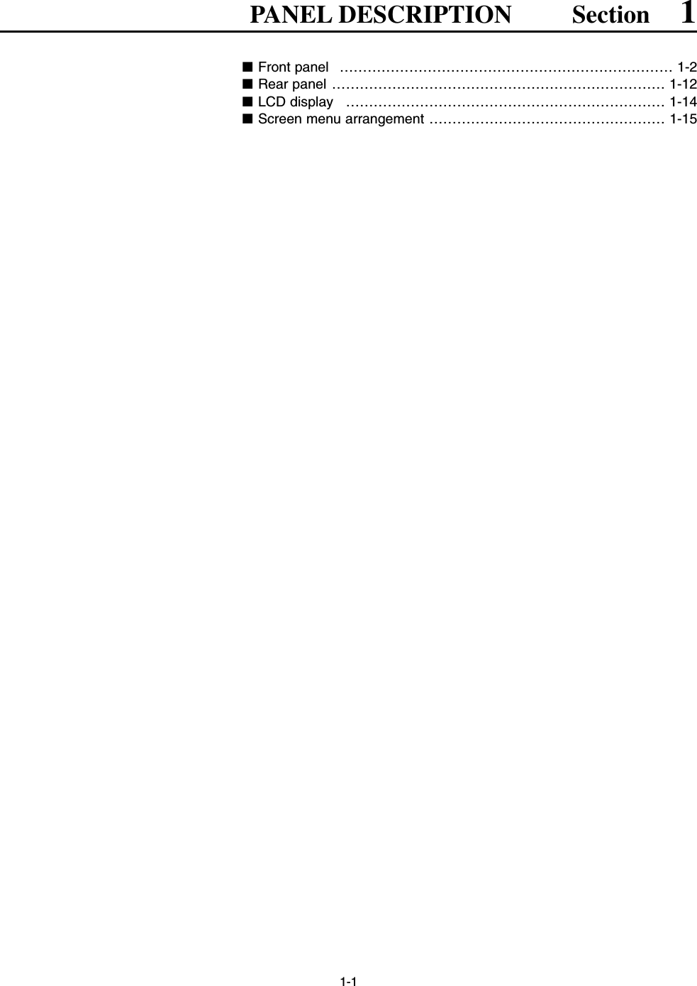
![1-3iMIC GAIN CONTROL [MIC]Adjusts microphone input gain.• The transmit audio tone in SSB, AM and FM modes canbe adjusted independently in set mode. (p. 12-4)✔How to set the microphone gain.Set the [MIC] control so that the ALC meter sometimesswings during normal voice transmission in SSB, AM or FMmode.oRF POWER CONTROL [RF PWR] (p. 3-12)Continuously varies the RF output power from min-imum (5 W*) to maximum (200 W*).*AM mode: 5 W to 50 W!0 VOX/BREAK-IN SWITCH [VOX/BK-IN]➥Push to turn the VOX function ON and OFF dur-ing SSB, AM and FM mode operation. (p. 6-2)➥Push to turn the break-in function ON (semi-break-in, full break-in) and OFF during CW mode opera-tion. (p. 6-3)➥Push for 1 sec. to enter VOX set mode. (p. 6-2)✔What is the VOX function?The VOX function (voice operated transmission) starts trans-mission without pushing the transmit switch or PTT switchwhen you speak into the microphone; then, automatically re-turns to receive when you stop speaking.✔What is the break-in function?The break-in function switches transmit and receive with CWkeying. Full break-in (QSK) can monitor the receive signalduring keying.!1 ELECTRONIC CW KEYER SPEED CONTROL[KEY SPEED] (p. 4-4)Adjusts the internal electronic CW keyer’s speed.• 6 wpm (min.) to 60 wpm (max.) can be set.!2 BREAK-IN DELAY CONTROL [DELAY] (p. 6-3)Adjusts the transmit-to-receive switching delay timefor CW semi break-in operations.!3 MONITOR SWITCH [MONI] (p. 6-4)Monitors your transmitted IF signal.• The CW sidetone functions regardless of [MONI] switchsetting in CW mode.• The [MONI] indicator above this switch lights greenwhile the function is activated.!4 MEMORY CARD SLOT [CF CARD] (p. 2-3)Insert the supplied CF (Compact Flash) memorycard for both reading/storing a variety of trans-ceiver’s information or data.• The indicator beside the slot lights or blinks when thetransceiver accessing to the memory card for reading orwriting data.• Push-in the eject button to remove the memory card.!5 MONITOR GAIN CONTROL [MONI GAIN] (p. 6-4)Adjusts the transmit IF signal monitor level.!6 COMPRESSION LEVEL CONTROL [COMP](p. 6-5)Adjusts the speech compression level in SSB.!7 DRIVE GAIN CONTROL [DRIVE] (p. 3-13)Adjusts the amplifying gain level at the drive stage.Activated in all modes (except SSB with [COMP] OFF).!8 VOX GAIN CONTROL [VOX GAIN] (p. 6-2)Adjusts the transmit/receive switching thresholdlevel for VOX operation.LowsensitivityHighsensitivityPushDecreasesIncreasesPushMonitor gaindecreasesMonitor gainincreasesPushMonitor gaindecreasesMonitor gainincreasesPushLong delay forslow speed keyingShort delay forhigh speed keyingMax.60 wpmMin.6 wpmIncreasesDecreasesRecommended level foran Icom microphoneDecreases Increases1PANEL DESCRIPTION](https://usermanual.wiki/ICOM-orporated/259000.Users-Manual-Part-1/User-Guide-397407-Page-12.png)
![1-4■Front panel (continued)!9 AGC CONTROL [AGC] (for MAIN band; p. 5-11)@0 AGC CONTROL [AGC] (for SUB band; p. 5-11)Adjusts the AGC circuit time constant.• To use the set value, push appropriate band’s [AGC VR]([AGC VR] indicator lights).@1 AGC VOLUME SWITCH [AGC VR](for MAIN band; p. 5-11)@2 AGC VOLUME SWITCH [AGC VR](for SUB band; p. 5-11)➥Push to toggle [AGC] control usage ON and OFF.• The set level with [AGC] control is used for the oper-ation when switched ON.• The [AGC VR] indicator above this switch lightsgreen when the control setting is in use.➥Turns the AGC function OFF when pushed for1 sec.@3 AF CONTROL [AF] (inner control; for SUB band)@4 AF CONTROL [AF] (inner control; for MAIN band)Varies the audio output level from the speaker.@5 RF GAIN CONTROL [RF] (outer control; for MAINband; p. 3-9)@6 RF GAIN CONTROL [RF] (outer control; for SUBband; p. 3-9)Adjusts the RF gain level. While rotating the RF gain control, noise may beheard. This comes from the DSP unit and doesnot indicate an equipment malfunction.@7 SQUELCH CONTROL [SQL] (outer control; forMAIN band; p. 3-9)@8 SQUELCH CONTROL [SQL] (outer control; forSUB band; p. 3-9)Adjusts the squelch threshold level. The squelch re-moves noise output from the speaker (closed con-dition) when no signal is received.• The squelch is particularly effective for FM. It is alsoavailable for other modes.• 11 to 12 o’clock position is recommended for any set-ting of the [SQL] control.DeepDeepS-metersquelchNoise squelchSquelchis open.SquelchthresholdShallowShallowSensitivityincreasesSensitivitydecreasesAudio outputincreasesAudio outputdecreasesSlowFast1PANEL DESCRIPTION@6@4@5@1@2@3@7 @8#2!9#0 #1@9@0#3 #4](https://usermanual.wiki/ICOM-orporated/259000.Users-Manual-Part-1/User-Guide-397407-Page-13.png)
![1-5@9 MULTI-FUNCTION SWITCHESPush to select the functions indicated in the LCDdisplay to the right of these switches.• Functions vary depending on the operating condition.➥Selects the antenna connector fromANT1, ANT2, ANT3 and ANT4 whenpushed. (p. 10-2)➥Displays antenna selection memorywhen pushed for 1 sec.• When the receive antenna is activated, theantenna which is connected to the [ANT4] isused for receive only.When a transverter is in use, this [ANT]does not function and ‘XVERT’ appears.➥Selects RF power (Po), SWR, ALC,COMP, VDor IDmetering during transmit.(p. 3-10)➥Switches the multi-function digital meterON and OFF when pushed for 1 sec.(p. 3-10)➥Selects one of 2 receive RF preamps orbypasses them. (p. 5-9)• “P. AMP1” activates 10 dB preamp.•“P. AMP2” activates 16 dB high-gain preamp.✔What is the preamp?The preamp amplifies received signals in the front end cir-cuit to improve the S/N ratio and sensitivity. Select “P. AMP1”or “P. AMP2” when receiving weak signals.➥Selects 6 dB, 12 dB or 18 dB attenuatorwhen pushed. (p. 5-9)➥Selects 3 dB, 6 dB, 9 dB, 12 dB, 18 dB,or 21 dB attenuator when pushed for1 sec. (p. 5-9)✔What is the attenuator?The attenuator prevents a desired signal from distortingwhen very strong signals are near the desired frequency, orwhen very strong electric fields, such as from a broadcast-ing station, are near your location.➥Activates or selects fast, middle or slowAGC time constant when pushed. (p. 5-11)• “FAST” is only available for FM mode.➥Enters the AGC set mode when pushedfor 1 sec. (p. 5-11)AGC time constant can be set between 0.1 to8.0 sec. (depends on mode), or turned OFF. While“OFF” is selected, the S-meter does not function.✔What is the AGC?The AGC controls receiver gain to produce a constant audiooutput level, even when the received signal strength is variedby fading, etc. Select “FAST” for tuning and select “MID” or“SLOW” depending on the receiving condition.➥Turns the speech compressor ON andOFF in SSB mode. (p. 6-5)➥Switches the narrow, middle or widetransmit filter when pushed for 1 sec.✔What is the speech compressor?The speech compressor compresses the transmitter audioinput to increase the average audio output level. Therefore, talkpower is increased. This function is effective for long distancecommunication or when propagation conditions are poor.➥Turns the 1⁄4function ON and OFF inSSB data, CW, RTTY and PSK modes.(p. 3-6)•1⁄4function sets dial rotation to 1⁄4of normalfor fine tuning.➥Switches the tone encoder, tone squelchfunction and no tone operation whenpushed in FM mode. (pgs. 4-32, 4-33)➥Enters the tone set mode when pushedfor 1 sec. in FM mode. (pgs. 4-32, 4-33)➥Switches the voice squelch control func-tion ON and OFF. (p. 9-3)#0 TRANSMIT INDICATOR [TX] (for MAIN band)#1 TRANSMIT INDICATOR [TX] (for SUB band)Lights red while transmitting.• SUB band’s [TX] indicator lights only when the split op-eration.#2 ANTI VOX CONTROL [ANTI VOX] (p. 6-2)Adjusts the VOX deactivate level to prevent un-wanted VOX control from the speaker audio.#3 LCD CONTRAST CONTROL [CONTRAST]Adjusts the LCD contrast.#4 LCD BRIGHTNESS CONTROL [BRIGHT]Adjusts the LCD brightness.DarkBrightPushLowcontrastHighcontrastPushDecreasescut-off levelIncreasescut-off levelPush1PANEL DESCRIPTION](https://usermanual.wiki/ICOM-orporated/259000.Users-Manual-Part-1/User-Guide-397407-Page-14.png)
![1-6■Front panel (continued)#5 NOISE REDUCTION SWITCH [NR] (for MAINband; p. 5-18)#6 NOISE REDUCTION SWITCH [NR] (for SUB band;p. 5-18)Push to switches the noise reduction ON and OFF.• The [NR] indicator above this switch lights green whenthe function is activated.#7 NOISE REDUCTION LEVEL CONTROL [NR](inner control; for SUB band; p. 5-18)#8 NOISE REDUCTION LEVEL CONTROL [NR](inner control; for MAIN band; p. 5-18)Adjusts the noise reduction level when the noise re-duction is in use. Set for maximum readability.• To activate this control, push the appropriate band’s[NR] in advance.#9 NOISE BLANKER CONTROL [NB] (outer control;for MAIN band; p. 5-17)$0 NOISE BLANKER CONTROL [NB] (outer control;for SUB band; p. 5-17)Adjust the noise blanker threshold level.• To activate this control, push appropriate band’s [NB]switch in advance.$1 NOISE BLANKER SWITCH [NB] (for MAIN band;p. 5-17)$2 NOISE BLANKER SWITCH [NB] (for SUB band;p. 5-17)➥Switches the noise blanker ON and OFF whenpushed. The noise blanker reduces pulse-typenoise such as that generated by automobile igni-tion systems. This function cannot be used forFM, or non-pulse-type noise.• The [NB] indicator above this switch lights greenwhile the function is activated.➥Enters blank-width set mode when pushed for1 sec.$3 RECEIVE INDICATOR [RX] (for MAIN band)$4 RECEIVE INDICATOR [RX] (for SUB band)Lights green while receiving a signal and when thesquelch is open.$5LOCK INDICATOR [LOCK] (for MAIN band; p. 5-18)$6 LOCK INDICATOR [LOCK] (for SUB band; p. 5-18)Lights when the dial lock function is activated.$7 SPLIT OPERATION INDICATOR [SPLIT]Lights during split frequency operation.$8 LCD FUNCTION DISPLAY (p. 1-14)Shows the operating frequency, function switchmenus, spectrum scope screen, memory channelscreen, set mode settings, etc.DeepShallowIncreasesDecreases1PANEL DESCRIPTION#5#6$1 $2#8#9$5$3 $6 $9$4$7 $8#7$0%0 %1 %3 %4 %6%2 %5](https://usermanual.wiki/ICOM-orporated/259000.Users-Manual-Part-1/User-Guide-397407-Page-15.png)
![1-7$9 MEMORY UP/DOWN SWITCHES [Y]/[Z](p. 8-2)Push to select the memory channel number for theselected readout.• Memory channels can be selected both in VFO andmemory modes.%0 LCD FUNCTION SWITCHES [F-1]–[F-7]Push to select the function indicated in the LCD dis-play above these switches.• Functions vary depending on the operating condition.%1 MODE SWITCHESSelects the desired mode. (p. 3-8)• Announces the selected mode. (p. 12-16)➥Selects USB and LSB modes alternately.➥Selects CW and CW-R (CW reverse)modes alternately.➥Switches RTTY and PSK mode whenpushed.➥Switches RTTY and RTTY-R (RTTY re-verse) mode when pushed for 1 sec. inRTTY mode.➥Switches PSK and PSK-R (PSK reverse)mode when pushed for 1 sec. in PSKmode.➥Selects AM and FM modes alternately.➥Selects SSB, AM or FM data mode (USB-D, LSB-D, AM-D, FM-D) when pushed inSSB, AM or FM mode, respectively.➥Switches D1, D2 and D3 when pushedfor 1 sec. %2 MINI SPECTRUM SCOPE SWITCH [M.SCOPE](p. 5-4)Turns the mini spectrum scope screen indicationON and OFF.• The mini spectrum scope screen can be indicated withanother screen, such as memory, set mode screen, si-multaneously.%3 VOICE MEMORY RECORD SWITCH [REC] (p. 7-3)➥Records the receiving signal contents for the pre-set time period when pushed.• After the preset time has passed, stops recording au-tomatically.➥Records the receiving signal contents until can-celling the record when pushed for 1 sec. • Push this switch momentarily to stops recording.• The memory records the latest 30 sec. audio only.%4 VOICE MEMORY PLAY BACK SWITCH [PLAY](p. 7-4)➥Play back the previously recorded audio for thepreset time period when pushed.➥Play back all of the previously recorded audiowhen pushed for 1 sec.%5 EXIT/SET SWITCH [EXIT/SET]➥Push to exits or returns to the previous screen in-dication during spectrum scope, memory, scan orset mode screen indication, etc.➥Displays set mode menu screen when pushedfor 1 sec.%6 TRANSMIT FREQUENCY CHECK SWITCH [XFC](p. 6-6)Monitors the transmit frequency (including ∂TX fre-quency setting) when pushed and held during thesplit frequency operation.• While pushing this switch, the transmit frequency can bechanged with the main dial, keypad, memo pad or[Y]/[Z] switches.• When the split lock function is turned ON, pushing [XFC]cancels the dial lock function. (p. 6-7)1PANEL DESCRIPTION](https://usermanual.wiki/ICOM-orporated/259000.Users-Manual-Part-1/User-Guide-397407-Page-16.png)
![1-8■Front panel (continued)%7 MEMO PAD-WRITE SWITCH [MP-W] (p. 8-7)Programs the selected readout frequency and op-erating mode into a memo pad.• The 5 most recent entries remain in memo pads.• The memo pad capacity can be expanded from 5 to 10in set mode for your convenience. (p. 12-16)%8 VFO/MEMORY SWITCH [V/M]➥Switches the selected readout operating modebetween the VFO mode and memory modewhen pushed. (pgs. 3-3, 8-2)➥Transfers the memory contents to VFO whenpushed for 1 sec. (p. 5-5)%9 KEYPAD➥Pushing a key selects the operating band.• [GENE•.] selects the general coverage band.➥Pushing the same key 2 or 3 times calls up otherstacked frequencies in the band. (p. 3-4)• Icom’s triple band stacking register memorizes 3 fre-quencies in each band.➥After pushing [F-INP•ENT], enters a keyed fre-quency or memory channel. Pushing [F-INP•ENT]or [Y/[Z] is necessary at the end. (pgs. 3-5, 8-2)• e.g. to enter 14.195 MHz, push [F-INP] [1.8•1] [10•4][GENE •] [1.8•1] [28•9] [14•5] [F-INP•ENT].^0 MEMORY WRITE SWITCH [MW] (p. 8-4)Stores the selected readout frequency and operat-ing mode into the displayed memory channel whenpushed for 1 sec.• This function is available both in VFO and memorymodes.^1 MEMO PAD-READ SWITCH [MP-R] (p. 8-7)Each push calls up a frequency and operating modein a memo pad. The 5 (or 10) most recently pro-grammed frequencies and operating modes can berecalled, starting from the most recent.• The memo pad capacity can be expanded from 5 to 10in set mode for your convenience. (p. 12-16)^2FILTER SWITCH [FILTER] (for MAIN band; p. 5-13)^3 FILTER SWITCH [FILTER] (for SUB band; p. 5-13)➥Selects one of 3 IF filter settings.➥Enters the filter set screen when pushed for1 sec.^4 AUDIO PEAK FILTER/TWIN PEAK FILTERSWITCH [APF/TPF] (for MAIN band)^5 AUDIO PEAK FILTER/TWIN PEAK FILTERSWITCH [APF/TPF] (for SUB band)➥Push to turn the audio peak filter ON and OFFduring CW mode operation. (p. 4-6)➥Push to turn the twin peak filter ON and OFF dur-ing RTTY mode operation. (p. 4-14)• “ ” appears when audio peak filter is in use.• “ ” appears when twin peak filter is in use.➥During CW mode operation, push for 1 sec. toselect the APF passband width from 80, 160 and320 Hz. (p. 4-6)TPFAPF1PANEL DESCRIPTION%7 %8 ^0 ^1%9&0 &8&1 &5&4&2 &6 &3 &7&9^2 ^3^5^4^6^7^9^8](https://usermanual.wiki/ICOM-orporated/259000.Users-Manual-Part-1/User-Guide-397407-Page-17.png)
![1-9^6 NOTCH SWITCH [NOTCH] (for SUB band; p. 5-19)^7NOTCH SWITCH [NOTCH] (for MAIN band; p. 5-19)➥Switches the notch function between auto, man-ual and OFF in SSB and AM modes.➥Turns the manual notch function ON and OFFwhen pushed in CW, RTTY and PSK31 mode.➥Turns the auto notch function ON and OFF whenpushed in FM mode.• “ ” appears when auto notch is in use.• “ ” appears when manual notch is in use.➥Switches the manual notch characteristics fromwide, middle and narrow when pushed for 1 sec. ✔What is the notch function?The notch function eliminates unwanted CW or AM carriertones while preserving the desired signal’s audio response.The filtering frequency is adjusted to effectively eliminate un-wanted tones via the DSP circuit.^8 DUALWATCH SWITCH [DUALWATCH] (p. 5-16)➥Turns the dualwatch function ON and OFF whenpushed.➥Turns the dualwatch function ON and equalizesthe main/sub readout frequency to the sub/mainreadout when pushed for 1 sec. (Quick dualwatchfunction)• The quick dualwatch function can be turned OFFusing set mode. (p. 12-13)^9 SPLIT SWITCH [SPLIT] (p. 6-6)➥Turns the split function ON and OFF whenpushed.➥Turns the split function ON, equalizes the subreadout frequency to the main readout and setsthe sub readout for frequency input when pushedfor 1 sec. in non-FM modes. (Quick split function)• The offset frequency is shifted from the main readoutfrequency in FM mode. (p. 12-14)• The quick split function can be turned OFF using setmode. (p. 12-14)➥Turns the split function ON and shifts the subreadout frequency after inputting an offset.&0 MAIN BAND ACCESS SWITCH [MAIN]Selects access to the main readout. • The main readout frequency is clearly displayed. Thesub readout functions only during split operation or du-alwatch.&1 MAIN/SUB EQUALIZING SWITCH [M=S]Equalizes the sub readout frequency to the mainreadout frequency when pushed for 1 sec.&2 AUTOMATIC TUNING SWITCH [AUTO TUNE](for MAIN band)&3 AUTOMATIC TUNING SWITCH [AUTO TUNE](for SUB band)Turns the automatic tuning function ON and OFF inCW and AM modes.&4 MAIN DIALChanges the displayed frequency (main band), se-lects set mode setting, etc.&5 MAIN/SUB CHANGE SWITCH [CHANGE]Switches the frequency and selected memorychannel between main and sub readouts whenpushed.• Switches between transmit frequency and receive fre-quency when the split frequency function is ON. (p. 6-6)&6 LOCK SWITCH [LOCK] (for MAIN band; p. 5-18)&7 LOCK SWITCH [LOCK] (for SUB band; p. 5-18)Push to switch the dial lock function ON and OFF. &8 SUB BAND ACCESS SWITCH [SUB]Selects access to the sub readout. • The sub readout frequency is clearly displayed. Themain readout functions only during split operation or du-alwatch.&9 SUB DIALChanges the displayed frequency in sub band.IMPORTANT!When receiving a weak signal, or receiving a sig-nal with interference, the automatic tuning func-tion may not be tuned, or tuned into an undesiredsignal.1PANEL DESCRIPTION](https://usermanual.wiki/ICOM-orporated/259000.Users-Manual-Part-1/User-Guide-397407-Page-18.png)
![1-10■Front panel (continued)*0 RIT/∂TX CONTROL [RIT/∂TX] (pgs. 5-10, 6-4)Shifts the receive and/or transmit frequency withoutchanging the transmit and/or receive frequencywhile the RIT and/or ∂TX functions are ON.• Rotate the control clockwise to increase the frequency,or rotate the control counterclockwise to decrease thefrequency.• The shift frequency range is ±9.999 kHz in 1 Hz steps(or ±9.99 kHz in 10 Hz steps).*1 PASSBAND TUNING CONTROLS [TWIN PBT](for MAIN band; p. 5-12)*2 PASSBAND TUNING CONTROLS [TWIN PBT](for SUB band; p. 5-12)Adjust the receiver’s “passband width” of the DSPfilter. • Passband width and shift frequency are displayed in themulti-function display.• Push [PBT CLEAR] for 1 sec. to clear the settings whennot in use.• Variable range is set to half of the IF filter passbandwidth. 25 Hz steps and 50 Hz steps are available.✔What is the PBT control?General PBT function electronically narrows the IF passbandwidth to reject interference. This transceiver uses the DSPcircuit for the PBT function.*3 PBT CLEAR SWITCH [PBT CLEAR](for MAIN band; p. 5-12)*4 PBT CLEAR SWITCH [PBT CLEAR](for SUB band; p. 5-12)Clears the PBT settings when pushed for 1 sec.• The [PBT CLEAR] indicator above this switch lightswhen PBT is in use.PBT1PBT2Low cutHigh cut Center–+FrequencyincreasesFrequencydecreases1PANEL DESCRIPTION*0(5 (6 (7 (8*3*1 *2*4*8*7*9(0(2(3(4*6*5(1](https://usermanual.wiki/ICOM-orporated/259000.Users-Manual-Part-1/User-Guide-397407-Page-19.png)
*6 DIGITAL RF SELECTOR CONTROL [DIGI-SEL](for SUB band; p. 5-19)Adjusts the digital RF selector center frequency.• The control can be used as the audio peak filter adjust-ment (p. 12-17)*7 DIGITAL RF SELECTOR SWITCH [DIGI-SEL](for MAIN band; p. 5-19)*8 DIGITAL RF SELECTOR SWITCH [DIGI-SEL](for SUB band; p. 5-19)Turns the digital RF selector ON and OFF.• The [DIGI-SEL] indicator lights green when the selectoris in use.*9 MANUAL NOTCH FILTER CONTROL [NOTCH](for SUB band; outer control; p. 5-19)(0 MANUAL NOTCH FILTER CONTROL [NOTCH](for MAIN band; outer control; p. 5-19)Varies the peak frequency of the manual notch fil-ter to pick out a receive signal from interferencewhile the manual notch function is ON.• Notch filter center frequency:SSB : –1060 Hz to 4040 HzCW : CW pitch freq. + 2540 Hz to CW pitch freq.–2540 Hz AM : –5100 Hz to 5100 Hz(1 CW PITCH CONTROL [CW PITCH] (p. 4-5)Shifts the received CW audio pitch and monitoredCW audio pitch without changing the operating fre-quency.(2 RIT SWITCH [RIT] (p. 5-10)➥Turns the RIT function ON and OFF whenpushed.• Use [RIT/∂TX] control to vary the RIT frequency.➥Adds the RIT shift frequency to the operating fre-quency when pushed for 1 sec.✔What is the RIT function?The RIT (Receiver Incremental Tuning) shifts the receive fre-quency without shifting the transmit frequency.This is useful for fine tuning stations calling you on an off-fre-quency or when you prefer to listen to slightly different-sounding voice characteristics, etc.(3 ∂TX SWITCH [∂TX] (p. 6-4)➥Turns the ∂TX function ON and OFF whenpushed.• Use [RIT/∂TX] control to vary the ∂TX frequency.➥Adds the ∂TX shift frequency to the operatingfrequency when pushed for 1 sec.✔What is the ∂TX function?The ∂TX shifts the transmit frequency without shifting the re-ceive frequency. This is useful for simple split frequency op-eration in CW, etc.(4 CLEAR SWITCH [CLEAR] (pgs. 5-10, 6-4)Clears the RIT/∂TX shift frequency when pushedfor 1 sec. or when pushed momentarily, dependingon the quick RIT/∂TX clear function setting (p. 12-17).(5 QUICK TUNING SWITCH [TS] (for MAIN band)(6 QUICK TUNING SWITCH [TS] (for SUB band)➥Turns the quick tuning step ON and OFF. (p. 3-6)• While the quick tuning indicator, “Z,” is displayedabove the frequency indication, the frequency can bechanged in programmed kHz steps.• 0.1, 1, 5, 9, 10, 12.5, 20 and 25 kHz steps are avail-able for each operating mode independently.➥When the quick tuning step is OFF, push for1 sec. to turn the 1 Hz tuning step ON and OFF.(p. 3-7)➥When the quick tuning step is ON, push for1 sec. to enter quick tuning step set mode. (p. 3-6)(7 SPEECH SWITCH [SPEECH] (for MAIN band; p. 13-3)(8 SPEECH SWITCH [SPEECH] (for SUB band; p. 13-3)➥Push to announce the S-meter indication and theselected readout frequency.➥The selected operating mode is additionally an-nounced when pushed for 1 sec.HighfrequencyLowfrequencyHigherfrequencyLowerfrequencyHigherfrequencyLowerfrequency1PANEL DESCRIPTION](https://usermanual.wiki/ICOM-orporated/259000.Users-Manual-Part-1/User-Guide-397407-Page-20.png)
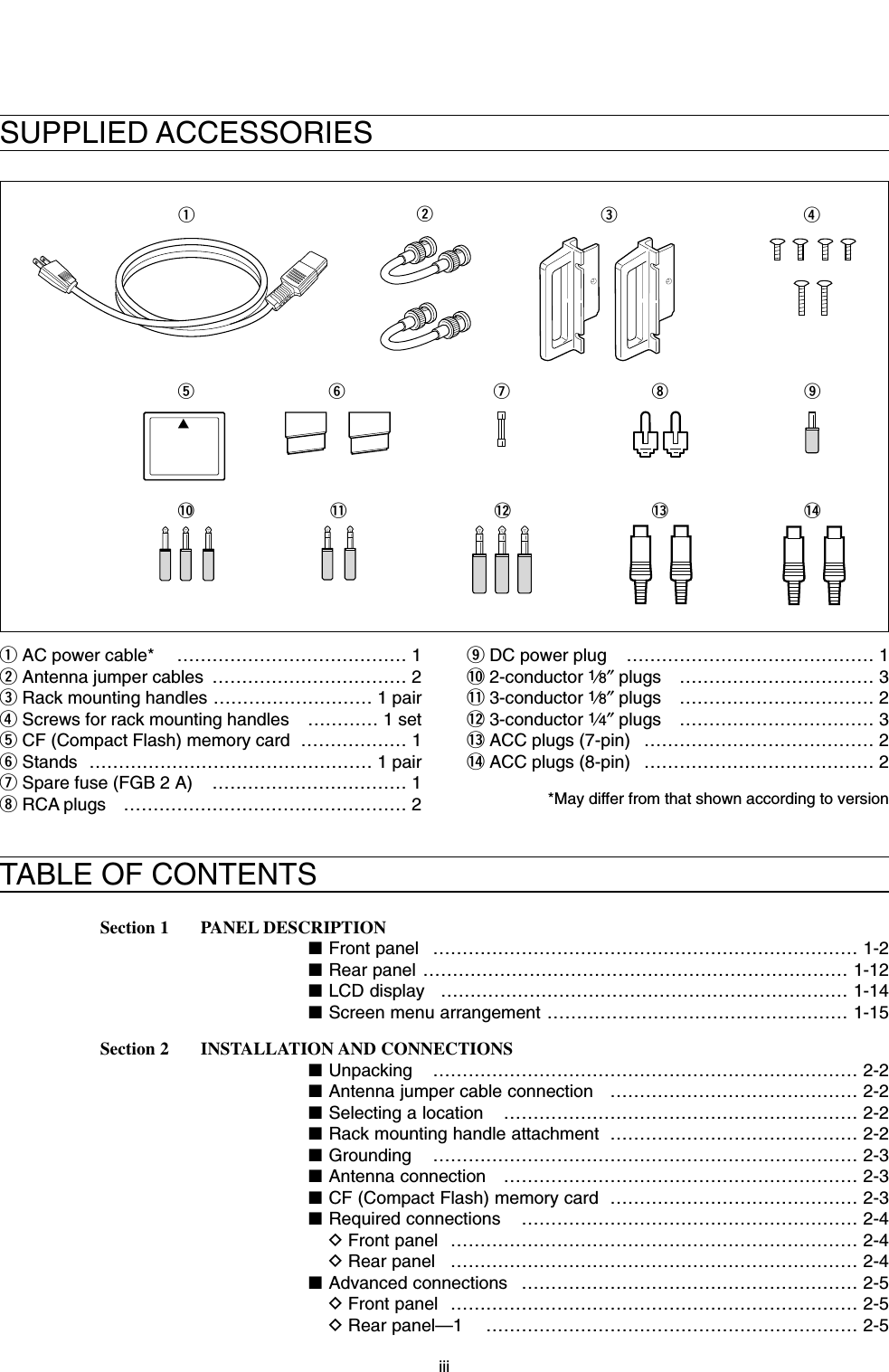
![1-12■Rear panelqANTENNA CONNECTOR 1 [ANT 1] (p. 2-4)wANTENNA CONNECTOR 2 [ANT 2] (p. 2-4)eANTENNA CONNECTOR 3 [ANT 3] (p. 2-4)rANTENNA CONNECTOR 4 [ANT 4] (p. 2-4)Accept a 50 Ωantenna with a PL-259 plug connec-tor.tGROUND TERMINAL [GND] (p. 2-3)Connect this terminal to a ground to prevent electri-cal shocks, TVI, BCI and other problems.yCIRCUIT BREAKERCuts off the AC input when over current occurs.uRECEIVE ANTENNA B OUT [RX ANT B– OUT]iRECEIVE ANTENNA B IN [RX ANT B– IN]Located between the transmit/receive switching cir-cuit and receiver’s RF stage in SUB band (MAINband during split operation).Connects an external unit, such as preamplifier, RFfilter, using BNC connector, if desired.When no external unit is connected, [RX ANT B–OUT] and [RX ANT B– IN] must be shorted with thesupplied coaxial cable. (p. 2-2)oTRANSVERTER CONNECTOR [X-VERTER] (p. 2-5)External transverter input/output connector.Activated by voltage applied to [ACC 2] pin 6, or thetransverter function is in use. (pgs. 2-10, 4-6)!0 RECEIVE ANTENNA A OUT [RX ANT A– OUT]!1 RECEIVE ANTENNA A IN [RX ANT A– IN]Located between the transmit/receive switching cir-cuit and receiver’s RF stage in MAIN band (SUBband during split operation).Connects an external unit, such as preamplifier, RFfilter, using BNC connector, if desired.When no external unit is connected, [RX ANT A–OUT] and [RX ANT A– IN] must be shorted with thesupplied coaxial cable. (p. 2-2)!2 MAIN POWER SWITCH [I/O] (p. 3-2)Turns the internal power supply ON and OFF.!3 AC POWER SOCKET [AC] (p. 2-4)Connects the supplied AC power cable to an ACoutlet.!4EXTERNAL SPEAKER JACK MAIN [EXT-SP MAIN](p. 2-5)!5 EXTERNAL SPEAKER JACK SUB [EXT-SP SUB](p. 2-5)Connects an external speaker (4–8 Ω), if desired.ReceiverTransmitterIN[RX ANT A/B]OUTTransmit/Receiveswitching circuit1PANEL DESCRIPTIONMAINSUBACC 1ACC 2ACC 1ACC 2ALCADJALCRELAYKEYEXTKEYPADMETERDC OUT15VMAX1AREF I/O10MHz-10dBmINOUTREMOTERS-232CKEY BOARDEXT-DISPLAYABS/P DIFEXT-SPANT 1 ANT 2 ANT 3 ANT 4GNDACIX-VERTERAINRX ANTBRX ANTOUT INOUTq w e r u i o !0 !1!4!5!7!9 !6!8@0@1@2@3@4@5@6@7@8@9#0#1#2#3!2!3t y](https://usermanual.wiki/ICOM-orporated/259000.Users-Manual-Part-1/User-Guide-397407-Page-21.png)
![1-13!6 ACCESSORY SOCKET 1 A [ACC 1–A]!7 ACCESSORY SOCKET 2 A [ACC 2–A]!8 ACCESSORY SOCKET 1 B [ACC 1–B]!9 ACCESSORY SOCKET 2 B [ACC 2–B]Enable connection of external equipment such as aliner amplifier, an automatic antenna selector/tuner,TNC for data communications, etc.• See p. 2-10 for socket information.@0 ALC LEVEL ADJUSTMENT POT [ALC ADJ] Adjusts the ALC levels.No adjustment is required when the ALC outputlevel of the connected non-Icom linear amplifier is0 to –4 V DC.@1 ALC INPUT JACK [ALC] (p. 2-7)Connects to the ALC output jack of a non-Icom lin-ear amplifier.@2 T/R CONTROL JACK [RELAY] (p. 2-7)Goes to ground when transmitting to control an ex-ternal unit.@3 STRAIGHT KEY JACK [KEY] (p. 2-4)Accepts a straight key or external electronic keyerwith 1⁄4inch standard plug.• [ELEC-KEY] on the front panel can be used for astraight key or external electronic keyer. Deactivate theinternal electronic keyer in keyer set mode. (p. 4-12)@4 EXTERNAL KEYPAD JACK [EXT KEYPAD] (p. 2-6)Connects an external keypad for direct voice mem-ory or electronic keyer control.Transceiver mute control (both transmit and re-ceive) line is also equipped.@5 METER JACK [METER] (p. 2-6)Outputs the receiving signal strength level signal,transmit output power, VSWR, ALC, speech com-pression, VDor IDlevel for external meter indication.@6 DC OUTPUT JACK [DC OUT] (p. 2-6)Outputs a regulated 14 V DC (approx.) for externalequipment. Connected in parallel with 13.8 V out-puts of [ACC 1] and [ACC 2]. (max. 1 A in total)@7 REFERENCE SIGNAL INPUT/OUTPUT TERMINAL [REF I/O]Inputs/outputs a 10 MHz reference signal.@8 S/P DIF INPUT TERMINAL [S/P DIF– IN] (p. 2-6)@9 S/P DIF OUTPUT TERMINAL [S/P DIF– OUT] (p. 2-6)Connects an external equipment, that S/P DIFinput/output are supported.#0 CI-V REMOTE CONTROL JACK [REMOTE] (p. 2-5)➥Connects a PC via the optional CT-17 CI-V LEVELCONVERTER for external control of the transceiverfunctions.➥Used for transceive operation with another IcomCI-V transceiver or receiver.#1 RS-232C TERMINAL [RS-232C] (p. 2-5)Connects an RS-232C cable, D-sub 9-pin to con-nect the IC-7800 to a PC. Can be used for remotely control the IC-7800 with-out the optional CT-17, or for RTTY/PSK31 de-coded signal output.#2 KEYBOARD CONNECTOR [KEYBOARD] (p. 2-6)Connects a PC keyboard for RTTY and PSK31 op-erations.• USB (Universal Serial Bus) type keyboard can be con-nected.#3 EXTERNAL DISPLAY TERMINAL[EXT-DISPLAY] (p. 2-6)Connects to an external display.• At least 800×600 pixel display is necessary.+__(+)(_)NOTE: T/R control voltage and current must belower than 16 V DC/0.5 A (or 250 V AC,200 mA with MOS-FET switching).1PANEL DESCRIPTION](https://usermanual.wiki/ICOM-orporated/259000.Users-Manual-Part-1/User-Guide-397407-Page-22.png)
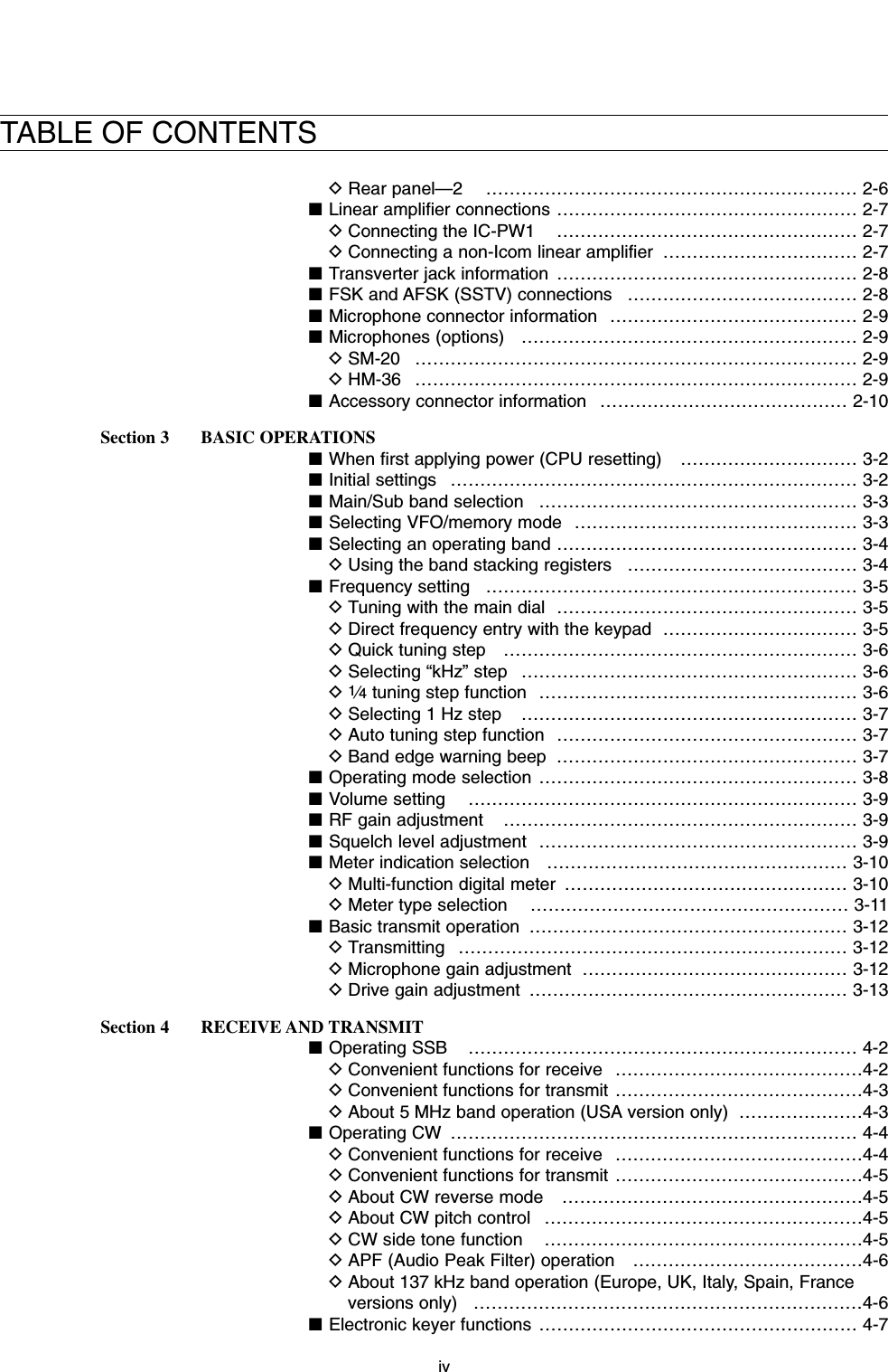
![■LCD displayqBAND WIDTH INDICATOR (p. 5-12)Shows the passband width of the IF filter.wMODE INDICATORShows the selected mode.eSHIFT FREQUENCY INDICATOR (p. 5-12)Shows the shift frequency of the IF filter.rQUICK TUNING INDICATOR (p. 3-6)Appears when the quick tuning step function is in use.tPASSBAND WIDTH INDICATOR (p. 5-12)Graphically displays the passband width for twinPBT operation and center frequency for IF shift op-eration.yBANDPASS FILTER INDICATORAppears when the narrow filter (500 Hz or less) isselected during CW, RTTY or PSK31 operation.uRTTY TUNING INDICATORShows the tuning level in RTTY mode.iCLOCK READOUTShows the current time.oS/RF METER (p. 3-10)Shows the signal strength while receiving. Showsthe relative output power, SWR, ALC or compres-sion levels while transmitting.!0 TX INDICATORIndicates the frequency readout for transmit.!1 VFO/MEMORY CHANNEL INDICATOR (p. 3-3)Indicates the VFO mode or selected memory chan-nel number.!2 IF FILTER INDICATORShows the selected IF filter number.!3 FREQUENCY READOUTSShows the operating frequency.• Outline characters are used for non-accessing readout.!4SELECT MEMORY CHANNEL INDICATOR (p. 9-7)Indicates the displayed memory channel is set as aselect memory channel.!5 MEMORY CHANNEL READOUTS➥Shows the selected memory channel contents inVFO mode.➥Shows the VFO contents in memory mode.!6 MULTI-FUNCTION SWITCH GUIDEIndicates the function of the multi-function switches.!7 LCD FUNCTION SWITCH GUIDEIndicates the function of the LCD function switches([F-1] – [F-7]).!8 MULTI-FUNCTION SCREENShows the screens for the multi-function digitalmeter, spectrum scope, voice recorder, memorychannel, scan, memory keyer, RTTY decoder, PSKdecoder, IF filter selection or set modes, etc.1-141PANEL DESCRIPTIONq w e t uy ir q w e t uyr!7 !4 !5!6!4!5!3!2!1!0o!8](https://usermanual.wiki/ICOM-orporated/259000.Users-Manual-Part-1/User-Guide-397407-Page-23.png)
![1-15■Screen menu arrangementThe following screens can be selected from the startup screen. Choose the desired screen using the fol-lowing chart.Pushing [EXIT/SET] several times returns to the startup screen. See p. 12-3 for set mode arrangement.1PANEL DESCRIPTION• Spectrum scope screen (p. 5-2)• Voice recoder screen (p. 7-3)• RTTY decoder screen (p. 4-13)• Memory keyer screen (CW mode; p. 4-8)• Memory channel screen (p. 8-3)• PSK31 decoder screen (p. 4-21)• Scan screen (VFO mode; p. 9-4)• Scan screen (Memory mode; p. 9-6)• Set mode menu screen (p. 12-2)](https://usermanual.wiki/ICOM-orporated/259000.Users-Manual-Part-1/User-Guide-397407-Page-24.png)
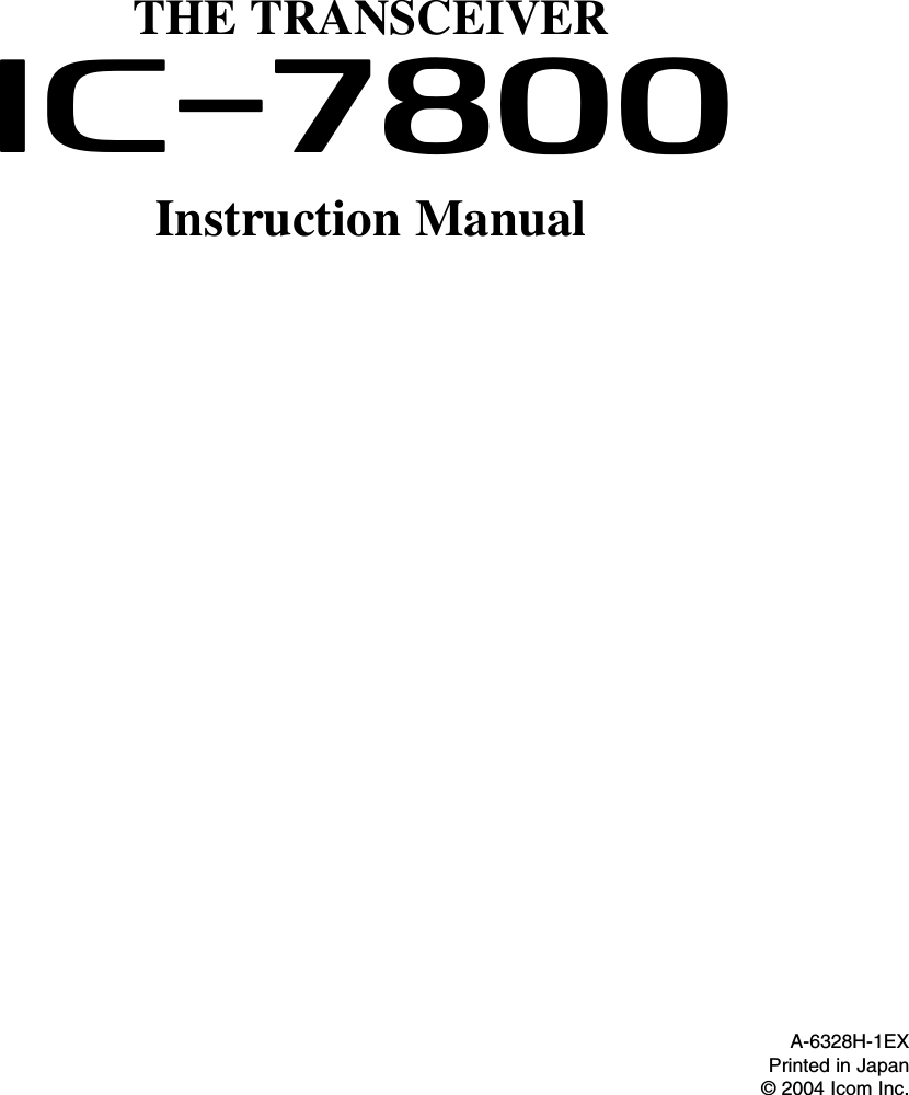
![2-2■UnpackingAfter unpacking, immediately report any damage to thedelivering carrier or dealer. Keep the shipping cartons.For a description and a diagram of accessory equip-ment included with the IC-7800, see ‘Supplied acces-sories’ on p. iii of this manual.■Antenna jumper cable connectionConnect the supplied coaxial cable (terminated withBNC connectors) between [RX ANT A— IN] and [RXANT A— OUT], and, [RX ANT B— IN] and [RX ANTB— OUT], respectively.When connecting an external filter unit, pre-amplifier,etc., connect the unit between [RX ANT A/B— IN] and[RX ANT A/B— OUT] connectors.■Selecting a locationSelect a location for the transceiver that allows ade-quate air circulation, free from extreme heat, cold, orvibrations, and away from TV sets, TV antenna ele-ments, radios and other electromagnetic sources.The base of the transceiver has an adjustable standfor desktop use. Set the stand to one of two angles de-pending on your operating conditions.■Rack mounting handle attachmentRemove the four screws from both sides of the frontpanel and the two screws from both sides of the sidepanel, then attach the rack mounting handles to thesides of the transceiver using the supplied screws.2INSTALLATION AND CONNECTIONS](https://usermanual.wiki/ICOM-orporated/259000.Users-Manual-Part-1/User-Guide-397407-Page-26.png)
![2-3■GroundingTo prevent electrical shock, television interference(TVI), broadcast interference (BCI) and other prob-lems, ground the transceiver through the GROUNDterminal on the rear panel.For best results, connect a heavy gauge wire or strapto a long earth-sunk copper rod. Make the distance be-tween the [GND] terminal and ground as short as pos-sible.RWARNING: NEVER connect the [GND]terminal to a gas or electric pipe, since the connec-tion could cause an explosion or electric shock.■Antenna connectionFor radio communications, the antenna is of critical im-portance, along with output power and sensitivity. Se-lect antenna(s), such as a well-matched 50 Ωantenna,and feedline. 1.5:1 or better of Voltage Standing WaveRatio (VSWR) is recommended for your desired band.Of course, the transmission line should be a coaxialcable.When using 1 antenna, use the [ANT1] connector.CAUTION: Protect your transceiver from lightningby using a lightning arrestor.■CF (Compact Flash) memory card Insert the supplied CF (Compact Flash) memorycard into the CF memory card slot. • To remove the CF memory card, push-in the button, lo-cated at left hand side of the slot.Make sure the direction of the memory card. NEVER insert or remove the CF memory cardduring accessing indicator lights or blinks.Accessing indicatorAntenna SWREach antenna is tuned for a specified frequencyrange and SWR may be increased out-of-range.When the SWR is higher than approx. 2.0:1, thetransceiver’s power drops to protect the final transis-tor. In this case, an antenna tuner is useful to matchthe transceiver and antenna. Low SWR allows fullpower for transmitting even when using the antennatuner. The IC-7800 has an SWR meter to monitor theantenna SWR continuously.2INSTALLATION AND CONNECTIONSPL-259 CONNECTOR INSTALLATION EXAMPLE30 mm ≈9⁄8in 10 mm ≈3⁄8in 1–2 mm ≈1⁄16 in30 mm10 mm (soft solder)10 mm1–2 mmsolder solderSoftsolderCoupling ringSlide the coupling ring down. Strip the cable jacket and soft solder.Slide the connector body on and solder it.Screw the coupling ring onto the connector body.Strip the cable as shown at left. Soft sol-der the center con-ductor.qwer](https://usermanual.wiki/ICOM-orporated/259000.Users-Manual-Part-1/User-Guide-397407-Page-27.png)
![2-4■Required connectionsDFront panelDRear panelMAINSUBACC 1ACC 2ACC 1ACC 2ALCADJALCRELAYKEYEXTKEYPADMETERDC OUT15VMAX1AREF I/O10MHz-10dBmINOUTREMOTERS-232CKEY BOARDEXT-DISPLAYABS/P DIFEXT-SPANT 1 ANT 2 ANT 3 ANT 4GNDACIX-VERTERAINRX ANTBRX ANTOUT INOUTStraight keyA jumper cable is connected.Antenna 1, 2, 3, 4 (p. 2-3)[Example]: ANT1 for 1.8–18 MHz bands, ANT 2 for 21–28 bandsANT3 for 50 MHz band, ANT 4 for receive antennaGround(p. 2-3)Use the heaviest gauge wire or strap available and make the connection as short as possible.Grounding prevents elec-trical shocks, TVI and oth-er problems.AC outletR WARNING:Use the supplied AC power cable only.Microphones (p. 2-9)CW keyA straight key can be used when the internal electronic keyer is turned OFF in keyer set mode. (p. 4-12)OptionalSM-20OptionalHM-362INSTALLATION AND CONNECTIONS](https://usermanual.wiki/ICOM-orporated/259000.Users-Manual-Part-1/User-Guide-397407-Page-28.png)
![2-5■Advanced connectionsDFront panelDRear panel— 1MAINSUBACC 1ACC 2ACC 1ACC 2ALCADJALCRELAYKEYEXTKEYPADMETERDC OUT15VMAX1AREF I/O10MHz-10dBmINOUTREMOTERS-232CKEY BOARDEXT-DISPLAYABS/P DIFEXT-SPANT 1 ANT 2 ANT 3 ANT 4GNDACIX-VERTERAINRX ANTBRX ANTOUT INOUTRX ANT A/B IN/OUTConnects an external preamp or lowpass filter.External speaker (p. 15-4)ACC sockets(pgs.2-8, 2-10)Antenna 1, 2, 3, 4 (p. 2-7)Connects a linear amplifier, antenna selector, etc.[X-VERTER]Connects a transverter for V/UHF band use.[RELAY], [ALC] (p.2-7)Used for connecting a non-Icom linear amplifier.SP-20(option)[REMOTE], [RS-232C] (p. 14-2)Used for computer control and transceive operation.The optional CT-17 is required when con-necting a PC to [REMOTE].MICHeadphonesCF (Compact Flash) memory cardThe AFSK modulation signal can also be input from [MIC].2INSTALLATION AND CONNECTIONS](https://usermanual.wiki/ICOM-orporated/259000.Users-Manual-Part-1/User-Guide-397407-Page-29.png)
![2-6DRear panel— 2MAINSUBACC 1ACC 2ACC 1ACC 2ALCADJALCRELAYKEYEXTKEYPADMETERDC OUT15VMAX1AREF I/O10MHz-10dBmINOUTREMOTERS-232CKEY BOARDEXT-DISPLAYABS/P DIFEXT-SPANT 1 ANT 2 ANT 3 ANT 4GNDACIX-VERTERAINRX ANTBRX ANTOUT INOUT[METER]Connects an external meter, etc.External DisplayConnects a monitor dis-play (at least 800×600resolution) directory.Video output signal can be turned ON and OFF in set mode (p. 12-12) [DC OUT]Outputs regulated 14 V (approx.) DC for external equipment power supply. (max. 1 A capacity)External keypadConnects an external keypad for direct voice memory and memory keyer controls.KeyboardConnects an USB type PC keyboard directly for RTTY/PSK31 operation, as well as other text edit operation.Connects a PC for audio signal data input/output.[S/P DIF— IN/OUT]3.5 (d) mm; 1⁄8″ plug1.5 kΩ±5%1.5 kΩ±5%2.2 kΩ±5%4.7 kΩ±5%S1(T1/M1)S2(T2/M2)S3(T3/M3)S4(T4/M4)USER EXTERNAL KEYPAD3.5 (d) mm; 1⁄8″ plugMAIN band meterSUB band meterMute switch: Mutes both transmission and reception when switched ON this switch for transceive operaton, etc.2INSTALLATION AND CONNECTIONS](https://usermanual.wiki/ICOM-orporated/259000.Users-Manual-Part-1/User-Guide-397407-Page-30.png)
![2-7■Linear amplifier connectionsDConnecting the IC-PW1DConnecting a non-Icom linear amplifierRWARNING:Set the transceiver output power and linear ampli-fier ALC output level referring to the linear amplifierinstruction manual.The ALC input level must be in the range 0 V to–4 V, and the transceiver does not accept positivevoltage. Non-matched ALC and RF power settingscould cause a fire or ruin the linear amplifier.The maximum control level of [RELAY] jack is DC16 V/0.5 A with initial setting, and 250 V/200 mA with“MOS-FET” setting (see p. 12-9 for details). Use anexternal relay unit when your non-Icom linear ampli-fier require the control level that higher voltageand/or larger current capacity.RF OUTPUT RF INPUTSENDALC50 Ωcoaxial cableTransceiverANT1ALCRELAYTo an antennaNon-Icom linear amplifierTo anantennaACC-1ANTANT2ANT1ACC 2INPUT1INPUT2REMOTEEXCITER11&2GNDGNDIC-PW1AC outlet(Non-European versions: 100–120/220–240 V European version : 230 V)GroundTransceiverREMOTERemote control cable (supplied with the IC-PW1)ACC cable (supplied with the IC-PW1)Be sure to connect the cableto the 7-pin ACC 2 jack.Coaxial cable(supplied with the IC-PW1)Coaxial cable**OptionalConnect[INPUT2]if necessary2INSTALLATION AND CONNECTIONS](https://usermanual.wiki/ICOM-orporated/259000.Users-Manual-Part-1/User-Guide-397407-Page-31.png)
![2-8■Transverter jack informationWhen 2 to 13.8 V is applied to pin 6 of [ACC 2], the [X-VERTER] connector is activated for transverter opera-tion and the antenna connectors do not receive ortransmit any signals. (p. 4-6)While receiving, [X-VERTER] connector can be acti-vated as an input terminal from an external transverter.While transmitting, the [X-VERTER] connector outputssignals of the displayed frequency at –20 dBm (22 mV)as signals for the external transverter.■FSK and AFSK (SSTV) connectionsTo connect a TNC or scan converter, etc., refer to thediagram below.Connect to serial port, parallel port, speaker jack, microphone jack and line IN/OUT jack, etc.See the instruction manual of the application for details.D AFSK operation• When connecting to [ACC 1]• When connecting to [MIC]• When using a PC application• When using a TNCPCRS-232CTNC or scan converterPTTAudio outputAF inputGNDAFSK outputAF inputGNDPTT*SQL input†*When using the VOX function, no need to connect. Refer to the instruction manual of the external equipment (TNC, etc.).†When connecting the squelch line, consult the necessary manual (TNC, etc.).qwertyui12345678zzxxccvv*zxcvzxcvbbn†n†bn†PCRS-232CTNC or scan converterConnect to serial port, parallel port, speaker jack, microphone jack and line IN/OUT jack, etc.See the instruction manual of the application for details.DFSK operation— when connecting to [ACC 1]• When using a PC application• When using a TNC12345678Rear panel viewRTTYGNDAFSENDRTTYGNDAFSENDRTTY OUTPUTGNDAUDIO INPUTPTTRTTY OUTPUTGNDAUDIO INPUTPTT12345678Transverter connector2INSTALLATION AND CONNECTIONS](https://usermanual.wiki/ICOM-orporated/259000.Users-Manual-Part-1/User-Guide-397407-Page-32.png)
![2-9■Microphone connector information(Front panel view)CAUTION: DO NOT short pin 2 to ground as thiscan damage the internal 8 V regulator.NOTE: DC voltage is applied to pin 1 for micro-phone operation. Take care when using a non-Icommicrophone.■Microphones (options)qUP/DOWN SWITCHES [UP]/[DN]Change the selected readout frequency or memorychannel.• Continuous pushing changes the frequency or memorychannel number continuously.• While pushing [XFC], the transmit readout frequency canbe controlled while in split frequency operation.• The [UP]/[DN] switch can simulate a key paddle. Presetin the keyer set mode. (p. 4-12)wPTT SWITCHPush and hold to transmit; release to receive.ePTT LOCK SWITCH (available for SM-20 only)Push to toggles between transmit and receive.D SM-20D HM-36qwqwey GND (PTT ground)t PTTr Main readout squelch switchq Microphone inputw +8 V DC outpute Frequency up/downu GND (Microphone ground)i Main readout AF output (varies with [AF]/[BAL])2INSTALLATION AND CONNECTIONS[MIC] FUNCTION DESCRIPTIONPin No.w+8 V DC output Max. 10 mAeFrequency up GroundFrequency down Ground through 470 ΩrSquelch open “Low” levelSquelch closed “High” level](https://usermanual.wiki/ICOM-orporated/259000.Users-Manual-Part-1/User-Guide-397407-Page-33.png)
![2-10■Accessory connector information2INSTALLATION AND CONNECTIONSACC 2PIN No.NAME DESCRIPTION SPECIFICATIONSACC 1PIN No.NAME DESCRIPTION SPECIFICATIONSNOTE: If the CW side tone level limit or beep levellimit is in use, the CW side tone or beep tone de-creases from the fixed level when the [AF] control isrotated above a specified level, respectively. (p. 12-5)12345678“High” level : More than 2.4 V1 RTTY Controls RTTY keying “Low” level : Less than 0.6 VOutput current : Less than 2 mA2 GND Connects to ground. Connected in parallel with ACC 2 pin 2.Input/output pin. Ground level : –0.5 V to 0.8 V3 SEND Goes to ground when transmitting. Output current : Less than 20 mAWhen grounded, transmits. Input current (Tx) : Less than 200 mAConnected in parallel with ACC 2 pin 3.4 MOD Modulator input. Input impedance : 10 kΩConnects to a modulator. Input level : Approx. 100 mV rmsAF detector output. Output impedance : 4.7 kΩ5 AF Fixed, regardless of [AF] position Output level : 100–300 mV rmsin default settings. (see notes below)6 SQLS Squelch output. SQL open : Less than 0.3 V/5 mAGoes to ground when squelch opens.SQL closed : More than 6.0 V/100 µA7 13.8 V 13.8 V output when power is ON. Output current : Max. 1 AConnected in parallel with ACC 2 pin 7.Control voltage : –4 V to 0 V8 ALC ALC voltage input. Input impedance : More than 10 kΩConnected in parallel with ACC 2 pin 5.1 8 V Regulated 8 V output. Output voltage : 8 V ±0.3 VOutput current : Less than 10 mA2 GND Same as ACC 1 pin 2.3 SEND Same as ACC 1 pin 3.4 BAND Band voltage output. Output voltage : 0 to 8.0 V(Varies with amateur band)5 ALC Same as ACC 1 pin 8.6TRVActivates [X-VERTER] input/output Input impedance : More than 10 kΩwhen “HIGH” voltage is applied. Input voltage : 2 to 13.8 V713.8 VSame as ACC 1 pin 7.1234567](https://usermanual.wiki/ICOM-orporated/259000.Users-Manual-Part-1/User-Guide-397407-Page-34.png)
![3-2■When first applying power (CPU resetting)Before first applying power, make sure all connectionsrequired for your system are complete by referring toSection 2. Then, reset the transceiver using the follow-ing procedure.Resetting CLEARS all programmed contents inmemory channels and returns programmed valuesin set mode to default values.qTurn the main power ON with [I/O] on the rearpanel.• The transceiver power is still OFF and the [POWER] in-dicator lights orange.wWhile pushing and holding [F-INP•ENT] and [MW],push [POWER] to turn power ON.• The CPU is reset.• The CPU start up and it takes approx. 5 sec.• The transceiver displays its initial VFO frequencieswhen resetting is complete.eCorrect the set mode settings after resetting, if de-sired.Under cooler temperatures, the LCD may appeardark and unstable after turning power ON. This isnormal and does not indicate any equipment mal-function.■Initial settingsAfter resetting the transceiver, set controls as shownin the figure below.[RF PWR]: Max. clockwise[MIC]: 10–12 o’clock[SQL]: Max. counter- clockwise[AGC]: 12 o’clock[DEGI-SEL]: 12 o’clock[NOTCH]: 12 o’clock[NB]: Max. counter clockwise[AF]: Max. counter- clockwise[MONI GAIN], [COMP], [DRIVE],[VOX GAIN], [ANTI VOX]: 12 o’clock[RF]: Max. clockwise[DELAY]: Max. clockwise[KEY SPEED]: 10–12 o’clock[CW PITCH]: 12 o’clock[NR]: Max. counter clockwise[F-INP•ENT][MW][I/O][POWER]3BASIC OPERATIONS](https://usermanual.wiki/ICOM-orporated/259000.Users-Manual-Part-1/User-Guide-397407-Page-36.png)
![■Main/Sub band selectionThe IC-7800 has 2 bands, main and sub bands. Themain band is displayed on the left hand side, and thesub band is displayed on the right hand side of theLCD. Some functions can only be accessed to the se-lected band and the transmission is only permitted forthe main band (except the split frequency operation). ➥Push [MAIN] to select the main band.• The key backlight for [MAIN] lights.• Main band’s frequency readout highlighted.➥Push [SUB] to select the sub band.• The key backlight for [SUB] lights.• Sub band’s frequency readout highlighted.■Selecting VFO/memory modeVFO is an abbreviation of Variable Frequency Oscilla-tor, and is commonly referred to as a main tuning func-tion.The main dial is often called the “VFO knob.”➥Push [V/M] to switch between VFO and memorymodes.• “VFO” appears when VFO mode, or the selected mem-ory channel number appears when memory mode is se-lected beside the frequency readout.• Pushing [V/M] for 1 sec. transfers the contents of the se-lected memory channel to VFO mode. (p. 8-5)“VFO” indicatorMemory channelnumber[V/M][MAIN] [SUB]3-33BASIC OPERATIONS](https://usermanual.wiki/ICOM-orporated/259000.Users-Manual-Part-1/User-Guide-397407-Page-37.png)
![3-4■Selecting an operating bandThe triple band stacking register provides 3 memoriesin one band. 3 sets of a frequency and operating modeon each band are automatically stored when used.If a band key is pushed once, the frequency and oper-ating mode last used are called up. When the key ispushed again, another stored frequency and operatingmode are called up.This function is convenient when you operate 3 oper-ating modes on one band. For example, one registeris used for a CW frequency, another for an SSB fre-quency and the other one for an RTTY frequency.See the table below for a list of the band available andthe default settings for each band.DUsing the band stacking registersqPush [14•5], then select a frequency and an oper-ating mode.• Frequency and operating mode are memorized in thefirst band stacking register.wPush [14•5] again, then select another frequencyand operating mode.• This frequency and operating mode are memorized inthe second band stacking register.ePush [14•5] again, then select another frequencyand operating mode.• This frequency and operating mode are memorized inthe third band stacking register.• When a fourth frequency and operating mode are se-lected on a band, the first register set in step q, is overwritten.[Example]: 14 MHz bandBand keys3BASIC OPERATIONSBAND REGISTER 1 REGISTER 2 REGISTER 31.8 MHz 1.900000 MHz CW 1.910000 MHz CW 1.915000 MHz CW3.5 MHz 3.550000 MHz LSB 3.560000 MHz LSB 3.580000 MHz LSB7 MHz 7.050000 MHz LSB 7.060000 MHz LSB 7.020000 MHz CW10 MHz 10.120000 MHz CW 10.130000 MHz CW 10.140000 MHz CW14 MHz 14.100000 MHz USB 14.200000 MHz USB 14.050000 MHz CW18 MHz 18.100000 MHz USB 18.130000 MHz USB 18.150000 MHz USB21 MHz 21.200000 MHz USB 21.300000 MHz USB 21.050000 MHz CW24 MHz 24.950000 MHz USB 24.980000 MHz USB 24.900000 MHz CW28 MHz 28.500000 MHz USB 29.500000 MHz USB 28.100000 MHz CW50 MHz 50.100000 MHz USB 50.200000 MHz USB 51.000000 MHz FMGeneral 15.000000 MHz USB 15.100000 MHz USB 15.200000 MHz USB](https://usermanual.wiki/ICOM-orporated/259000.Users-Manual-Part-1/User-Guide-397407-Page-38.png)
![3-5■Frequency settingThe transceiver has several tuning methods for conve-nient frequency tuning.DTuning with the main dialqPush the desired band key on the keypad 1–3times.• 3 different frequencies can be selected on each bandwith the band key.• Push [MAIN] or [SUB] to select the band in advance.wRotate the main dial to set the desired frequency inmain band, rotate the sub dial to set the desired fre-quency in sub band.If the dial lock function is activated, the lock indicatorlights, and the main dial does not function. In thiscase, push [LOCK] to deactivate the lock function.(see p. 5-18 for details)✔CONVENIENT!The sub dial is available for when tuning frequency insub band. The sub dial allows quick tuning in sub bandwithout main/sub band selection.DDirect frequency entry with the keypadThe transceiver has a keypad for direct frequencyentry as described below.qPush [MAIN] or [SUB] to select the band.wPush [F-INP•ENT].• “ ” indicator appears and keypad backlightlights.eInput the desired frequency • Push [GENE•.] to input “. (decimal point)” between theMHz units and kHz units.rPush [F-INP•ENT] to set the input frequency.• To cancel the input, push [Y]/[Z] instead of [GENE•.].[EXAMPLE]7.00000 MHz21.24000 MHz21.24000 MHz ⇒ 21.36000 MHzPushPushPushKeypadBand keysMain dial Sub dial3BASIC OPERATIONS](https://usermanual.wiki/ICOM-orporated/259000.Users-Manual-Part-1/User-Guide-397407-Page-39.png)
![3-6DQuick tuning stepThe operating frequency can be changed in kHz steps(0.1, 1, 5, 9, 10, 12.5, 20 or 25 kHz selectable) forquick tuning.qPush [TS] to turn the quick tuning function ON.•“Z” appears when the quick tuning function ON.wRotate the main dial to change the frequency in pro-grammed kHz steps.ePush [TS] again to turn OFF the indicator.rRotate the main dial for normal tuning if desired.DSelecting “kHz” stepqPush [TS] to turn the quick tuning function ON andOFF.•“Z” appears when the quick tuning function ON.wPush [TS] for 1 sec. to enter tuning step setting dis-play.• Selected tuning steps for all modes appear.eSelect the desired operating mode.rRotate the main dial to select the desired tuning step.tRepeat steps eand rto select quick tuning stepsfor other modes, if desired.yPush [EXIT/SET] to exit the setting display.NOTE: When entering into quick tuning step setmode, the quick tuning function must be activated,and the set mode can be accessed from eitherband’s quick tuning switch, [TS]. Therefore, use thesame band’s [TS] for quick tuning function selectionand the set mode entering.D1⁄4tuning step functionWhen operating in SSB data, CW, RTTY or PSK, the1⁄4tuning function is available. Dial rotation is reducedto 1⁄4of normal when the 1⁄4tuning function is in use.➥Push [1/4] to toggle the 1⁄4tuning function ON andOFF.• “ ” appears when the 1⁄4tuning function ON 1⁄41⁄4 tuning step OFF 1⁄4 tuning step ONMain dial [TS]Select mode [TS]3BASIC OPERATIONSQuick tuning indicator Quick tuning indicator](https://usermanual.wiki/ICOM-orporated/259000.Users-Manual-Part-1/User-Guide-397407-Page-40.png)
![3-7DSelecting 1 Hz stepThe minimum tuning step of 1 Hz can be used for finetuning.qPush [TS] to turn the quick tuning function OFF.wPush [TS] for 1 sec. to turn the 1 Hz tuning step ONand OFF.NOTE: 1 Hz tuning step activates for both main andsub bands simultaneously. Therefore, either [TS]can be used for the 1 Hz tuning step selection.DAuto tuning step functionWhen rotating main or sub dial rapidly, the tuningspeed accelerated automatically as selected.qPush [EXIT/SET] several times to close a multi-function screen, if necessary.wPush [F-7•SET] to select set mode menu screen.• Pushing and holding [EXIT/SET] for 1 sec. also selectsset mode menu screen.ePush [F-5•OTHERS] to enter miscellaneous (oth-ers) set mode.rPush [F-1•Y] or [F-2•Z] to select “MAIN DIAL AutoTS” or “SUB DIAL Auto TS.”• “MAIN DIAL Auto TS” for main dial, “SUB DIAL Auto TS”for sub dial selection.tRotate main dial to select the desired condition fromhigh, low and OFF.• High : Approx. 5 times faster• Low : Approx. twice faster• OFF : Auto tuning step is turned OFF.yPush [EXIT/SET] to exit the set mode.DBand edge warning beepWhen selecting a frequency, that lies outside of a band’sspecified frequency range, a warning beep sounds.This function can be turned OFF in set mode, if de-sired.qPush [EXIT/SET] several times to close a multi-function screen, if necessary.wPush [F-7•SET] to select set mode menu screen.• Pushing and holding [EXIT/SET] for 1 sec. also selectsset mode menu screen.ePush [F5•OTHERS] to enter miscellaneous (others)set mode.rPush [F-1•Y] or [F-2•Z] to select “Beep (BandEdge).”tRotate main dial to turn the band edge warningbeep ON and OFF.yPush [EXIT/SET] to exit the set mode.[F-1•Y][F-2•Z][F5•OTHERS][EXIT/SET] [F-7•SET]1Hz step indicator 1Hz step indicator3BASIC OPERATIONS](https://usermanual.wiki/ICOM-orporated/259000.Users-Manual-Part-1/User-Guide-397407-Page-41.png)
![3-8■Operating mode selectionSSB (USB/LSB), SSB data (USB data/LSB data), CW,CW reverse (CW-R), RTTY, RTTY reverse (RTTY-R),PSK, PSK reverse (PSK-R), AM, AM data, FM and FMdata modes are available in the IC-7800. Select thedesired operation mode as follows.To select a mode of operation, push the desired modeswitch momentarily. Push the switch again to togglebetween USB and LSB, CW and CW-R, RTTY/RTTY-R and PSK/PSK-R, AM and FM, if necessary. Push theswitch for 1 sec. to toggle between RTTY and RTTY-R, PSK and PSK-R, if necessary.See the diagram below left for the order of selection.Microphone signals are muted when data mode isselected.• Selecting SSB mode➥Push [SSB] to select USB or LSB.• USB is selected first when above 10 MHz; or LSB is se-lected first when below 10 MHz operation.(USB is selected when 5 MHz band is selected for theUSA version.)• After USB or LSB is selected, push [SSB] to toggle be-tween USB and LSB.• Selecting CW mode➥Push [CW] to select CW.• After CW is selected, push [CW] to toggle between CWand CW reverse mode.• Selecting RTTY/PSK mode➥Push [RTTY/PSK] to select RTTY or PSK.• After RTTY or PSK is selected, push [RTTY/PSK] to tog-gle between RTTY and PSK.• After RTTY or PSK is selected, push [RTTY/PSK] for1 sec. to toggle between RTTY and RTTY reverse, or,PSK and PSK reverse mode, respectively.• Selecting AM/FM mode➥Push [AM/FM] to select AM or FM.• After AM or FM is selected, push [AM/FM] to toggle be-tween AM and FM.• Selecting DATA mode➥After USB, LSB, AM, synchronous AM or FM is se-lected, push [DATA] to select USB data, LSB data,AM data, synchronous AM data or FM data mode,respectively.• After data mode is selected, push [DATA] to toggle be-tween regular voice and data mode.• After data mode is selected, push [DATA] for 1 sec. toselect data 1, 2 and 3 in sequence.USBCWAMPush mode switch for 1 sec.Push mode switchmomentarily.LSBCW-RRTTY-R RTTY PSK PSK-RFMUSBLSBAMFMUSB-D1LSB-D1AM-D1FM-D1USB-D2LSB-D2AM-D2FM-D2USB-D3LSB-D3AM-D3FM-D3[SSB] [CW] [RTTY/PSK] [AM/FM] [DATA]3BASIC OPERATIONS](https://usermanual.wiki/ICOM-orporated/259000.Users-Manual-Part-1/User-Guide-397407-Page-42.png)
![3-9■Volume setting➥Rotate [AF] control clockwise to increase; counter-clockwise to decrease the audio output level.• Set a suitable audio level.■RF gain adjustment➥Rotate [RF] control clockwise to increase; counter-clockwise to decrease the receiver sensitivity.■Squelch level adjustmentThe squelch removes noise output from the speaker(closed position) when no signal is received.➥When no signal is received, rotate [SQL] controlfully counterclockwise first, then rotate [SQL] clock-wise to the point that the noise just disappears.[SQL] for main [SQL] for subS-meter squelchNoise squelch (Recommended level; FM mode only)Squelch is open[RF] for main [RF] for subSensitivityincreasesSensitivitydecreases[AF] for main [AF] for subAudio outputincreasesAudio outputdecreases3BASIC OPERATIONS](https://usermanual.wiki/ICOM-orporated/259000.Users-Manual-Part-1/User-Guide-397407-Page-43.png)
![■Meter indication selectionThe S/RF meter indication, during transmit, can be se-lected from the following items as your desired.➥Push [METER] several times to select the desireditem.Indicates the relative RF output power inwatts.Indicates the VSWR over the transmis-sion line.Indicates the ALC level. The ALC circuitbegins to activate when the RF outputpower reaches a preset level.Indicates the compression level whenthe speech compressor is in use.Indicates the drain’s current of the finalFETs.Indicates the drain’s terminal voltage ofthe final FETs.DMulti-function digital meterThe IC-7800 can display the multi-function digitalmeter in the LCD display, which displays all transmitmeters simultaneously.qPush [METER] for 1 sec. to turn the multi-functiondigital meter ON.wPush [F-1•P-HOLD] to toggle the peak level holdfunction ON.• “P-HOLD” appears on the window title when the peaklevel hold function is turned ON.ePush [METER] for 1 sec., or push [EXIT/SET] toturn the multi-function digital meter OFF.“P-HOLD” indicatorSID051015001044ALC 52VVD20dB11.5 23∞10 50 100 150 200 250POSWRCOMPAW159+20 +40 +60dBSignal strengthlevel readoutID readoutPower level readoutVSWR readoutCompression levelreadout ALC level readout VD readout[METER]3-103BASIC OPERATIONS](https://usermanual.wiki/ICOM-orporated/259000.Users-Manual-Part-1/User-Guide-397407-Page-44.png)
![3-11DMeter type selectionTotal of 3 meter types are available in the IC-7800—Standard, Edgewise and Bar meters. Follow the instructions below for the meter type selec-tion.qPush [EXIT/SET] several times to return to normalscreen, if necessary.wPush [F-7•SET], then push [F-3•DISPLAY] to selectdisplay set mode.ePush [F-1•Y] or [F-2•Z] to select “Meter type (Nor-mal Screen)” item.rRotate main dial to select the desired meter typefrom “Standard,” “Edgewise” and “Bar.”tPush [EXIT/SET] to exit display set mode.• Edgewise meter• Bar meter[F-1•Y] [EXIT/SET][F-7•SET][F-2•Z][F-3•DISPLAY]3BASIC OPERATIONS](https://usermanual.wiki/ICOM-orporated/259000.Users-Manual-Part-1/User-Guide-397407-Page-45.png)
![3-12■Basic transmit operationDTransmittingBefore transmitting, monitor your selected operatingfrequency to make sure transmitting won’t cause inter-ference to other stations on the same frequency. qPush [TRANSMIT] or [PTT] (microphone) to trans-mit.• The main band’s [TX] indicator lights red.• When the split operation is activated, the sub band’s [TX]indicator lights.wPush [TRANSMIT] again or release [PTT] (micro-phone) to return to receive.✔Adjusting the transmit output power➥Rotate [RF PWR].• Adjustable range : 5 W to 200 W (AM mode: 5 W to 50 W)DMicrophone gain adjustmentBefore transmitting, monitor your selected operatingfrequency to make sure transmitting won’t cause inter-ference to other stations on the same frequency. qPush [METER] to select the ALC meter.wPush [PTT] (microphone) to transmit.• Talk into the microphone at your normal voice level.eWhile talking into the microphone, rotate [MIC] sothat the ALC meter reading doesn’t go outside theALC zone. (see at left)rRelease [PTT] (microphone) to return to receive.SID051015001044ALC 52VVD20dB11.5 23∞10 50 100 150 200 250POSWRCOMPAW159+20 +40 +60dBALC zone[MIC] [METER]Increasesmax. 200 W(50 W for AM)Decreasesmin. 5 W[TRANSMIT][RF PWR] [TX] indicatorBefore transmitting, monitor your selected oper-ating frequency to make sure transmitting won’tcause interference to other stations on the samefrequency. It’s good Amateur practice to listenfirst, and then, even if nothing is heard, ask “isthe frequency in use” once or twice, before youbeing operating on that frequency.3BASIC OPERATIONS](https://usermanual.wiki/ICOM-orporated/259000.Users-Manual-Part-1/User-Guide-397407-Page-46.png)
![3-13DDrive gain adjustmentThe drive gain can be activated for the all modes ex-cept SSB without speech compressor to adjust the am-plifying gain at the drive stage.Before transmitting, monitor your selected operatingfrequency to make sure transmitting won’t cause inter-ference to other stations on the same frequency. qPush [METER] to select the ALC meter.wPush [PTT] (microphone; SSB with [COMP] ON, AMor FM), key down (CW) or push [TRANSMIT] (RTTYor PSK) to transmit.eWhile talking into the microphone, keying down ortransmitting, rotate [DRIVE] so that the ALC meterreading swinging within 30 to 50% of the ALC scale.(see left) • Talk into the microphone at your normal voice level.rRelease [PTT], stop keying or push [TRANSMIT]again to return to receive.[DRIVE][METER]3BASIC OPERATIONSSID051015001044ALC 52VVD20dB11.5 23∞10 50 100 150 200 250POSWRCOMPAW159+20 +40 +60dBDrive gain range](https://usermanual.wiki/ICOM-orporated/259000.Users-Manual-Part-1/User-Guide-397407-Page-47.png)