ICOM orporated 259000 Amateur HF Scanning Transceiver User Manual IC 7800 Eng
ICOM Incorporated Amateur HF Scanning Transceiver IC 7800 Eng
Contents
- 1. Users Manual Part 1
- 2. Users Manual Part 2
- 3. Users Manual Part 3
- 4. Users Manual Part 4
- 5. Users Manual Part 5
Users Manual Part 5
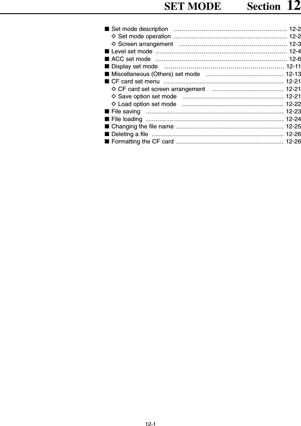
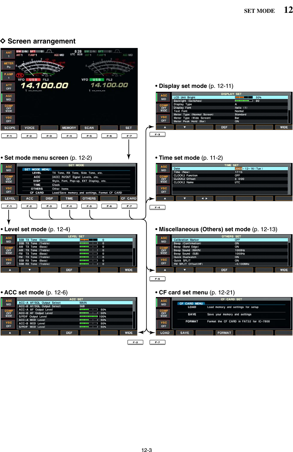
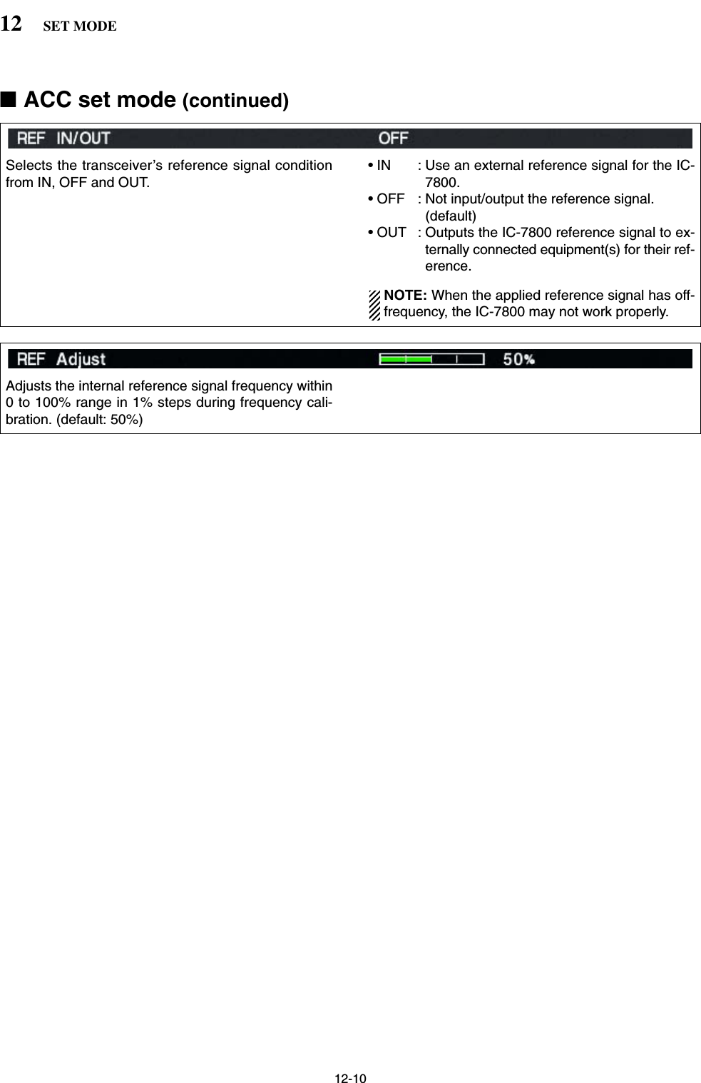
![12-2■Set mode descriptionSet mode is used for programming infrequentlychanged values or conditions of functions. The IC-7800 has a level set mode, display set mode, timer setmode, accessory set mode and miscellaneous (others)set mode.DSet mode operationqPush [EXIT/SET] several times to close a multi-function screen, if necessary.wPush [F-7•SET] to select set mode menu screen.• Pushing and holding [EXIT/SET] for 1 sec. also selectsset mode menu screen.ePush [F-1•LEVEL], [F-2•ACC], [F-3•DISP],[F-4•TIME], [F-5•OTHERS] or [F-7•CF CARD] toenter the desired set mode.rFor level, accessory, display and miscellaneous(others) set mode, push [F-7•WIDE] to toggle wideand normal screen.tPush [F-1•Y] or [F-2•Z] to select the desired item,then rotate main dial to adjust/select the desiredvalue or condition.• Pushing [F-3•Ω≈] operation may be necessary forsome items.yPush [EXIT/SET] twice to exit set mode.[F-1•LEVEL] [F-2•ACC][F-3•DISP][F-5•OTHERS][F-4•TIME][EXIT/SET] Main dial[F-7•CF CARD]12 SET MODE](https://usermanual.wiki/ICOM-orporated/259000.Users-Manual-Part-5/User-Guide-397411-Page-2.png)
![12-612 SET MODE■Level set mode (continued)Sets the ratio for audio output level from the head-phone toward to the internal speaker within 0.60 to1.40 range in 0.01 steps. (default: 1.00)Selects the headphone audio output. • OFF : Outputs the main band’s audio from the left,and sub band’s audio from the right. (default)• ON : Outputs the mixed audio.Selects the desired band for the audio and squelchsignals output from [ACC1–A] (Audio: pin 5, Squelch:pin 6) from MAIN and SUB.• MAIN : Main band’s AF and squelch signals areoutput from [ACC1–A]. (default)• SUB : Sub band’s AF and squelch signals are out-put from [ACC1–A].Selects the desired band for the audio and squelchsignals output from [ACC1–B] (Audio: pin 5, Squelch:pin 6) from MAIN and SUB.• MAIN : Main band’s AF and squelch signals areoutput from [ACC1–A].• SUB : Sub band’s AF and squelch signals are out-put from [ACC1–A]. (default)Sets the desired audio output level, output from[ACC1–A], within 0 to 100% in 1% steps.• Outputs approx. 200 mV at 50% (default) setting.Sets the desired audio output level, output from[ACC1–B], within 0 to 100% in 1% steps.• Outputs approx. 200 mV at 50% (default) setting.Sets the desired output level of [S/P DIF], within 0 to100% in 1% steps. (default: 100%)Sets the desired audio input level for modulation from[ACC1–A].• Approx. 100 mV at 50% (default) setting.■ACC set mode](https://usermanual.wiki/ICOM-orporated/259000.Users-Manual-Part-5/User-Guide-397411-Page-6.png)
![12-712SET MODESets the desired audio input level for modulation from[ACC1–B].• Approx. 100 mV at 50% (default) setting.Sets the desired input level for modulation from[S/P DIF], within 0 to 100% in 1% steps. (default: 50%)■ACC set mode (continued)Selects the desired connector(s) for modulation inputwhen data mode is not in use.• MIC : Use the signals from [MIC].• ACC-A : Use the signals from [ACC1–A](pin 4).• ACC-B : Use the signals from [ACC1–B](pin 4).• MIC,ACC-A : Use the signals from [MIC] and[ACC1–A] (pin 4).• MIC,ACC-B : Use the signals from [MIC] and[ACC1–B] (pin 4).• ACC-A,ACC–B : Use the signals from [ACC1–A]and [ACC1–B] (pin 4).• MIC,ACC-A,ACC–B: Use the signals from [MIC],[ACC1–A] and [ACC1–B] (pin 4).(default)• S/P DIF : Use the signals from [S/P DIF].Selects the desired connector(s) for modulation inputwhen data 1 mode (D1) is in use.• MIC : Use the signals from [MIC].• ACC-A : Use the signals from [ACC1–A](pin 4). (default)• ACC-B : Use the signals from [ACC1–B](pin 4).• MIC,ACC-A : Use the signals from [MIC] and[ACC1–A] (pin 4).• MIC,ACC-B : Use the signals from [MIC] and[ACC1–B] (pin 4).• ACC-A,ACC–B : Use the signals from [ACC1–A]and [ACC1–B] (pin 4).• MIC,ACC-A,ACC–B: Use the signals from [MIC],[ACC1–A] and [ACC1–B] (pin 4).• S/P DIF : Use the signals from [S/P DIF].](https://usermanual.wiki/ICOM-orporated/259000.Users-Manual-Part-5/User-Guide-397411-Page-7.png)
![12-812 SET MODE■ACC set mode (continued)Selects the desired band for the operating frequencyband control signal output from (pin 4).• MAIN : Outputs the band signal displayed in mainreadout.• SUB : Outputs the band signal displayed in subreadout.• TX : Outputs the band signal, that can be trans-mitted. (default)Selects the desired connector(s) for modulation inputwhen data 2 mode (D2) is in use.• MIC : Use the signals from [MIC].• ACC-A : Use the signals from [ACC1–A](pin 4).• ACC-B : Use the signals from [ACC1–B](pin 4). (default)• MIC,ACC-A : Use the signals from [MIC] and[ACC1–A] (pin 4).• MIC,ACC-B : Use the signals from [MIC] and[ACC1–B] (pin 4).• ACC-A,ACC–B : Use the signals from [ACC1–A]and [ACC1–B] (pin 4).• MIC,ACC-A,ACC–B: Use the signals from [MIC],[ACC1–A] and [ACC1–B] (pin 4).• S/P DIF : Use the signals from [S/P DIF].Selects the desired connector(s) for modulation inputwhen data 3 mode (D3) is in use.• MIC : Use the signals from [MIC].• ACC-A : Use the signals from [ACC1–A](pin 4).• ACC-B : Use the signals from [ACC1–B](pin 4).• MIC,ACC-A : Use the signals from [MIC] and[ACC1–A] (pin 4).• MIC,ACC-B : Use the signals from [MIC] and[ACC1–B] (pin 4).• ACC-A,ACC–B : Use the signals from [ACC1–A]and [ACC1–B] (pin 4). (default)• MIC,ACC-A,ACC–B: Use the signals from [MIC],[ACC1–A] and [ACC1–B] (pin 4).• S/P DIF : Use the signals from [S/P DIF].Selects the desired band for the operating frequencyband control signal output from [ACC2–A] (pin 4).• MAIN : Outputs the band signal displayed in mainreadout.• SUB : Outputs the band signal displayed in subreadout.• TX : Outputs the band signal, that can be trans-mitted. (default)](https://usermanual.wiki/ICOM-orporated/259000.Users-Manual-Part-5/User-Guide-397411-Page-8.png)
![12-912SET MODESelects the switching relay type for [RELAY] fromLead and MOS-FET.Select the suitable relay type when connecting a non-Icom linear amplifier.• Lead : Use mechanical relay. (16 V DC/0.5 A max.; default)• MOS-FET: Use semiconductor type relay.(200 mA/250 V max.)■ACC set mode (continued)Selects the desired item for an external meter indica-tion (main readout).• Auto : Outputs the receiving signal strength levelduring receive, and outputs the selectedcontent’s level, selected with [METER],during transmit. (default)• S(MAIN) : Outputs the receiving signal strength levelduring receive.• Po : Outputs the transmitting power level dur-ing transmit.• SWR : Outputs the VSWR level during transmit.• ALC : Outputs the ALC level during transmit.• COMP : Outputs the compression level duringtransmit.•VD: Outputs the drain’s terminal voltage of thefinal FETs.•ID: Outputs the drain’s current of the finalFETs.Selects the desired item for an external meter indica-tion (sub readout).• Auto : Outputs the receiving signal strength levelduring receive, and outputs the selectedcontent’s level, selected with [METER],during transmit. (default)• S(MAIN) : Outputs the receiving signal strength levelduring receive.• Po : Outputs the transmitting power level dur-ing transmit.• SWR : Outputs the VSWR level during transmit.• ALC : Outputs the ALC level during transmit.• COMP : Outputs the compression level duringtransmit.•VD: Outputs the drain’s terminal voltage of thefinal FETs.•ID: Outputs the drain’s current of the finalFETs.Sets the output level for an external meter indication(main readout) with in 0 to 100% range in 1% steps.• Approx. 2.5 V at 50% (default) setting for full-scale indica-tion. (4.7 kΩimpedance)Sets the output level for an external meter indication(sub readout) with in 0 to 100% range in 1% steps.• Approx. 2.5 V at 50% (default) setting for full-scale indica-tion. (4.7 kΩimpedance)](https://usermanual.wiki/ICOM-orporated/259000.Users-Manual-Part-5/User-Guide-397411-Page-9.png)
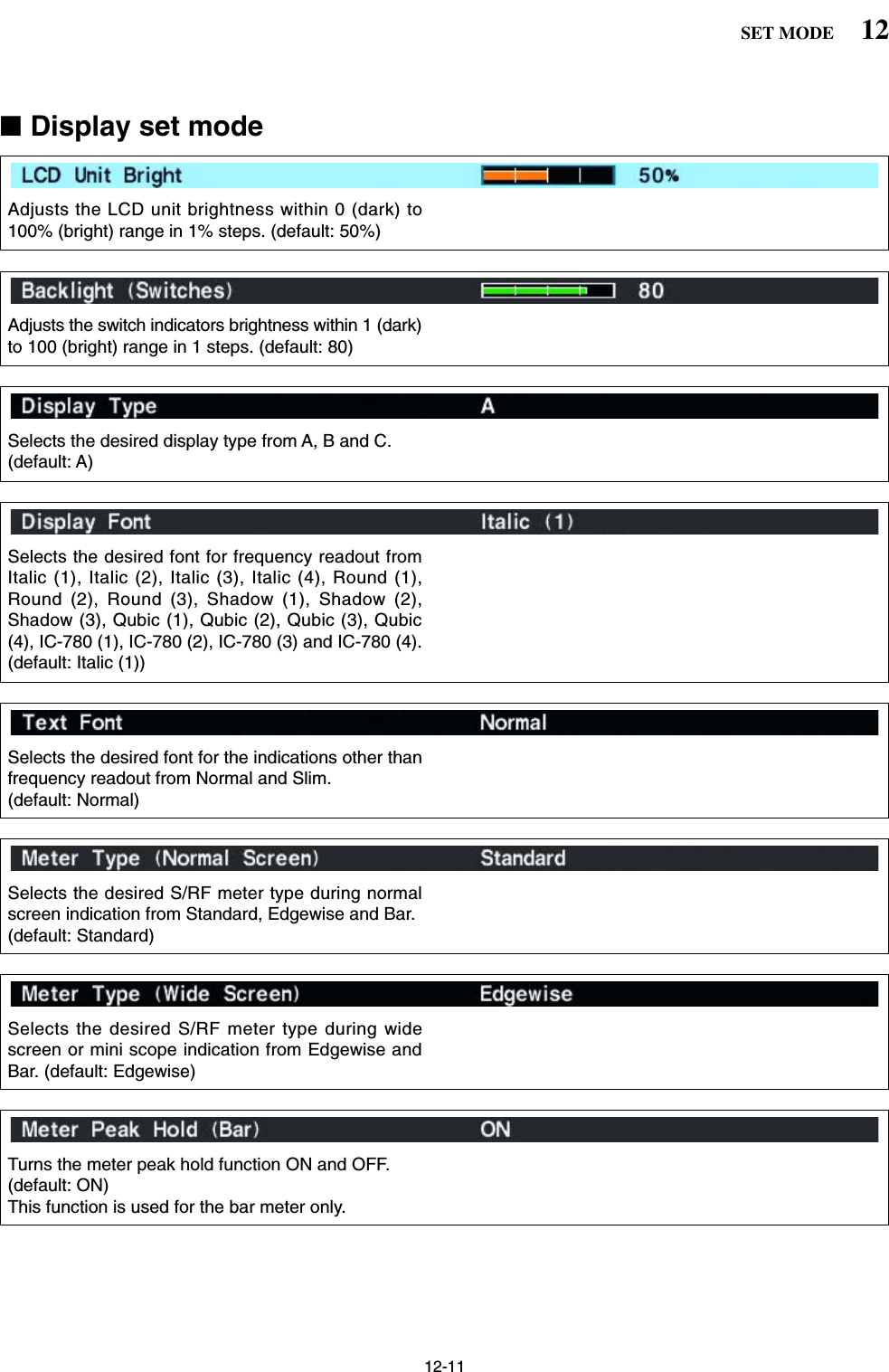
![12-1212 SET MODESets the desired 10-character text, such as your callsign, name, etc.The set text is indicated in the opening screen.Capital letters, small letters, numerals, some symbols(– / . @) and spaces can be used.zPush [F-5•EDIT] to select the name edit condition.• The 1st character and cursor blink.xPush [ABC], [abc], [123] or [Symbol] to select thecharacter group, then rotate the main dial to selectthe character.• Push [ABC] or [abc] to toggle capital and small letters.• Push [123] or [Symbol] to toggle numerals and sym-bols.• Push [F-1•Ω] or [F-2•≈] for cursor movement.• Push [F-3•DEL] to delete the selected character.• Push [F-4•SPACE] to input a space.• Pushing the transceiver’s keypad, [0]–[9], can alsoenter numerals.cPush [EXIT/SET] to set the name.Turns the pop-up indication capability when the filterwidth for the APF is changed from ON and OFF.(default: ON)Turns the pop-up indication capability when the notchfilter width is changed from ON and OFF. (default: ON)Select “ON” when the external display is connected. (default: OFF)• At least 800×600 pixel resolution is required for the dis-play.Selects the suitable pulse level for the connected ex-ternal display from H and L. (default: H)Turns the opening message screen indication capa-bility ON and OFF. (default: ON)Sets the memory name indication, during memorymode operation, ON and OFF. (default: ON)• ON : The programmed memory name is displayedabove the frequency indication.• OFF : No memory name is displayed even a mem-ory name is programmed.■Display set mode (continued)](https://usermanual.wiki/ICOM-orporated/259000.Users-Manual-Part-5/User-Guide-397411-Page-12.png)
![12-1312SET MODE■Miscellaneous (Others) set mode This item is used for a simple frequency check of thetransceiver. (default: OFF)See p. 13-5 for calibration procedure.NOTE: Turn the calibration marker OFF afterchecking the frequency of the transceiver.A beep sounds each time a switch is pushed to con-firm it. This function can be turned OFF for silent op-eration. (default: ON)The beep output level can be set in level set mode.(p. 12-5)A beep sounds when an operating frequency entersor exits an amateur band. This functions independentof the confirmation beep setting (above). (default: ON)The beep output level can be set in level set mode.(p. 12-5)Sets the desired key-touch beep sound frequencyduring main readout operation within 500 to 2000 Hzin 10 Hz steps. (default: 1000 Hz)Set the different frequency from “Beep Sound (SUB)”as below to distinguish between main and sub.Sets the desired key-touch beep sound frequencyduring sub readout operation within 500 to 2000 Hz in10 Hz steps. (default: 1000 Hz)Set the different frequency from “Beep Sound (MAIN)”as above to distinguish between main and sub.When this item is set to ON, pushing [DUALWATCH]for 1 sec. sets the sub readout frequency to the mainreadout frequency and activates dualwatch operation.(default: ON)See p. 5-16 for details.](https://usermanual.wiki/ICOM-orporated/259000.Users-Manual-Part-5/User-Guide-397411-Page-13.png)
![12-1412 SET MODE■Miscellaneous (Others) set mode (continued)Sets the offset (difference between transmit and re-ceive frequencies) for the quick split function. How-ever, this setting is used for HF bands in FM modeonly and is used to input the repeater offset for an HFband.The offset frequency can be set from –9.999 MHz to+9.999 MHz in 1 kHz steps. (default: –0.100 MHz)Sets the offset (difference between transmit and re-ceive frequencies) for the quick split function. How-ever, this setting is used for 50 MHz band FM modeonly, and is used to input the repeater offset for the50 MHz band.The offset frequency can be set from –9.999 MHz to+9.999 MHz in 1 kHz steps. (default: –0.500 MHz)When this item is ON, the main dial can be used toadjust the transmit frequency while pushing [XFC]even while the lock function is activated. (default: OFF)See pgs. 6-6, 6-7 for split frequency operation details.The internal antenna tuner has an automatic start ca-pability which starts tuning if the SWR is higher than1.5–3:1.• OFF : The tuner remains OFF even when the SWRis poor (1.5–3:1). (default)• ON : Automatic tune starts even when the tuner isturned OFF during HF bands operation. Tuning of the internal antenna tuner can be startedautomatically at the moment the PTT is pushed afterthe operating frequency is changed (more than 1%from last-tuned frequency). (default: OFF)When this item is set to ON, pushing [SPLIT] for 1sec. sets the sub readout frequency to the main read-out frequency and activates split operation.(default: ON)See p. 6-7 for details.](https://usermanual.wiki/ICOM-orporated/259000.Users-Manual-Part-5/User-Guide-397411-Page-14.png)
![12-1512SET MODESelects the transverter operation condition from Autoand ON. (default: Auto)• ON : Turn the transverter operation ON.• Auto : The transceiver turns into transverter opera-tion condition when 2 to 13.8 V DC is appliedto [ACC2–A/B] pin 6.Sets the desired offset frequency for the transverteroperation within 0.000 to 99.999 MHz in 1 kHz steps.(default: 16.000 MHz)■Miscellaneous (Others) set mode (continued)Selects the RTTY mark frequency. RTTY mark fre-quency is switched between 1275, 1615 and2125 Hz. (default: 2125 Hz)2125 Hz is automatically selected when the internalRTTY decoder is used.Selects the RTTY shift width. There are 3 selectablevalues: 170, 200 and 425 Hz. (default: 170 Hz)170 Hz is automatically selected when the internalRTTY decoder is used.Selects the RTTY keying polarity. Normal or reversekeying polarity can be selected.(default: Normal)When reverse polarity is selected, Mark and Spaceare reversed.• Normal : Key open/close = Mark/Space• Reverse : Key open/close = Space/MarkSelects the desired PSK tone frequency for the PSKreception from 1000, 1500 and 2000 Hz. (default: 1500 Hz)Selects the speech language from English and Japan-ese. (default: English)Selects the speech speed from HIGH (faster) andLOW (slower). (default: HIGH)](https://usermanual.wiki/ICOM-orporated/259000.Users-Manual-Part-5/User-Guide-397411-Page-15.png)
![12-1612 SET MODE■Miscellaneous (Others) set mode (continued)Selects the main dial function from MAIN andMAIN/SUB. (default: MAIN/SUB)• MAIN : The main dial functions only when ac-cessing to main readout.• MAIN/SUB : The main dial functions when access-ing to main readout, as well as whenaccessing to sub readout with [SUB]switch operation.Sets the auto tuning step function for the main dial.When rotating the main dial rapidly, the tuning stepautomatically changes several times as selected. There are 2 type of auto tuning steps: HIGH (Fastest)and LOW (Faster). (default: HIGH)• HIGH : Auto tuning step is turned ON. Fastest tun-ing step during rapid rotation. (default)• LOW : Auto tuning step is turned ON. Faster tun-ing step during rapid rotation.• OFF : Auto tuning step is turned OFF.Sets the auto tuning step function for the sub dial.When rotating the sub dial rapidly, the tuning step au-tomatically changes several times as selected. There are 2 type of auto tuning steps: HIGH (Fastest)and LOW (Faster). (default: HIGH)• HIGH : Auto tuning step is turned ON. Fastest tun-ing step during rapid rotation. (default)• LOW : Auto tuning step is turned ON. Faster tun-ing step during rapid rotation.• OFF : Auto tuning step is turned OFF.Sets the number of memo pad channels available. 5or 10 memo pads can be set. (default: 5)The IC-7800 speech processor has frequency, modeand signal level announcement. Signal level an-nouncement can be deactivated if desired.(default: ON)When “OFF” is selected, the signal level is not an-nounced.Turns the operating mode speech capability when amode switch is pushed from ON and OFF. (default: OFF)When “ON” is selected, the selected operating modeis announced when a mode switch is pushed.](https://usermanual.wiki/ICOM-orporated/259000.Users-Manual-Part-5/User-Guide-397411-Page-16.png)
![12-1712SET MODESelects [DIGI-SEL] control function from DIGI-SELand APF.• DIGI-SEL : [DIGI-SEL] control functions as the digi-tal selector operation. (default)• APF : [DIGI-SEL] control functions as theaudio peak filter adjustment.Sets the rate at which frequencies are scanned whenthe microphone [UP]/[DN] switches are pushed andheld. High or low can be selected.• HIGH : High speed (default; 50 tuning steps/sec.)• LOW : Low speed (25 tuning steps/sec.)Selects the RIT/∂TX frequency clearing instructionwith the [CLEAR] switch.• ON : Clears the RIT/∂TX frequency when [CLEAR]is pushed momentarily. • OFF : Clears the RIT/∂TX frequency when [CLEAR]is pushed for 1 sec. (default)Selects usable notch function for SSB mode opera-tion from Auto, Manual and Auto/Manual.• Auto : The auto notch can only be used.• Manual : The manual notch can only be used.• Auto/Manual : Both the auto and manual notch canbe used. (default)Selects usable notch function for AM mode operationfrom Auto, Manual and Auto/Manual.• Auto : The auto notch can only be used.• Manual : The manual notch can only be used.• Auto/Manual : Both the auto and manual notch canbe used. (default)■Miscellaneous (Others) set mode (continued)Selects filter set screen indication condition from Fixand Auto (by FILTER,PBT Operation). • Fix : When filter screen accessed with the mainband’s [FILTER] switch, the screen showsmain band’s filter width and PBT conditionsonly; when filter set screen accessed with thesub band’s [FILTER] switch, the screen showssub band’s filter width and PBT conditions only.• Auto (by FILTER,PBT Operation): Filter set screen indication can be switched be-tween main and sub bands filter width and PBTconditions when either band’s [FILTER] switchor [TWIN PBT] control is operated. (default)](https://usermanual.wiki/ICOM-orporated/259000.Users-Manual-Part-5/User-Guide-397411-Page-17.png)
![12-1812 SET MODESelects the displayed frequency shift function fromON and OFF. (default: OFF)When this function is activated, the receiving signalcan be kept to receive even when the operating modeis changed between SSB and CW. The frequency shifting value may differ accordingto the CW pitch setting.• ON : The displayed frequency shifts when the op-erating mode is changed between SSB andCW.• OFF : The displayed frequency does not shift.Selects the carrier point of CW mode from LSB andUSB. (default: LSB)Selects the desired band(s) for audio output from[MIC] connector (pin 8) from MAIN+SUB and SUB.(default: MAIN+SUB)• MAIN+SUB : Outputs both main and sub bandsaudio.• SUB : Outputs sub band audio only.Sets the external keypad for voice memory transmis-sion capability ON and OFF.See page 2-6 for the equivalent circuit of an externalkeypad and connection. • ON : Pushing one of external keypad switches,transmits the desired voice memory contentsduring a phone mode operation.• OFF : External keypad does not function. (default)Sets the external keypad for keyer memory transmis-sion capability ON and OFF.See page 2-6 for the equivalent circuit of an externalkeypad and connection. • ON : Pushing one of external keypad switches,transmits the desired keyer memory contentsduring CW mode operation. • OFF : External keypad does not function. (default)sets the data transfer rate. 300, 1200, 4800, 9600,19200 bps and “Auto” are available. (default: Auto)When “Auto” is selected, the baud rate is automati-cally set according to the connected controller or re-mote controller.■Miscellaneous (Others) set mode (continued)](https://usermanual.wiki/ICOM-orporated/259000.Users-Manual-Part-5/User-Guide-397411-Page-18.png)
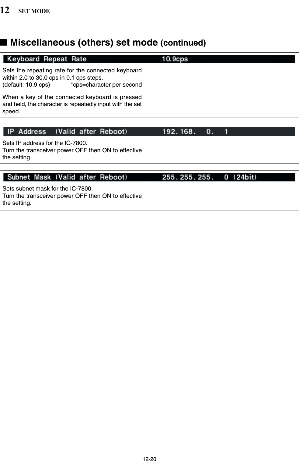
![12-1912SET MODE■Miscellaneous (Others) set mode (continued)Transceive operation is possible with the IC-7800connected to other Icom HF transceivers or receivers.When “ON” is selected, changing the frequency, op-erating mode, etc. on the IC-7800 automaticallychanges those of connected transceivers (or re-ceivers) and vice versa.Select [RS-232C] connector output data format fromCI-V and Decode.• CI-V : Outputs data in CI-V format. (default)• Decode : Outputs decoded contents in ASCII codeformat.Selects data transmission speed (Baud rate) when“Decode” is selected in “RS-232C Function” abovefrom 300, 1200, 4800, 9600 and 19200 bps. (default: 9600)Selects the connected keyboard type from Japaneseand English. (default: Japanese)Sets the time period for delay within 100 to1000 msec. in 50 msec. steps. (default: 250 msec.)When a key of the connected keyboard is pressedand held for the set period, the character is input con-tinuously.To distinguish equipment, each CI-V transceiver hasits own Icom standard address in hexadecimal code.The IC-7800’s address is 6Ah.When 2 or more IC-7800’s are connected to an op-tional CT-17 CI-V LEVEL CONVERTER, rotate the main dialto select a different address for each IC-7800 in therange 01h to 7Fh.](https://usermanual.wiki/ICOM-orporated/259000.Users-Manual-Part-5/User-Guide-397411-Page-19.png)
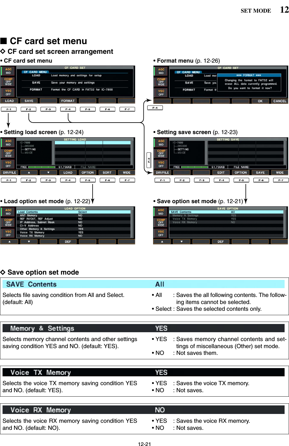
![12-2312SET MODE■File savingMemory channel contents, set mode settings, etc. canbe saved into the CF (Compact Flash) memory cardfor backup.qDuring set mode menu screen indication, push [F-7•CF CARD] to select CF card set menu screen.wPush [F-2•SAVE] to select setting save screen.eChange the following conditions if desired.• File name:zPush [F-4•EDIT] to select file name edit con-dition.• Push [F-1• DIR/FILE] several times to select thefile name, if necessary.xPush [ABC], [123] or [Symbol] to select thecharacter group, then rotate the main dial toselect the character.• [ABC] : A to Z (capital letters); [123]: 0 to 9 (nu-merals); [Symbol]: ! # $ % & ‘ ` ^ + – = ( ) [ ] { } _ ~@ can be selected.• Push [F-1•Ω] to move the cursor left, push [F-2•≈]to move the cursor right, push [F-3•DEL] to deletea character and push [F-4•SPACE] to insert aspace.cPush [EXIT/SET] to set the file name.• Save optionzPush [F-5•OPTION] to enter save option setmode.xPush [F-1•Y] or [F-2•Z] to select the item,then rotate the main dial to select the desiredsetting. (see p. 12-21 for details)• “Text” is the default setting.• Push [F-4•DEF] for 1 sec. to select the default set-ting.cPush [EXIT/SET] to return to the previous in-dication.• Saving locationzPush [F-1•DIR/FILE] to select tree viewscreen.xSelect the desired directory or folder in the CFmemory card.• Push [F-4•Ω≈] to select the upper directory.• Push [F-2•Y] or [F-3•Z] to select folder in thesame directory.• Push [F-4•Ω≈] for 1 sec. to select a folder in thedirectory.• Push [F-5•REN/DEL] to rename the folder.• Push [F-5•REN/DEL] for 1 sec. to delete thefolder.• Push [F-6•MAKE] for 1 sec. to making a newfolder. (Edit the name with the same manner asthe “• File name” above.)cPush [F-1•DIR/FILE] twice to select the filename.rPush [F-6•SAVE].• Confirmation screen appears.tPush [F-6•OK] to save.• After the saving is completed, return to CF card setmenu automatically.[F-1•DIR/FILE][F-5•OPTION][F-4•EDIT][F-6•SAVE]/[F-6•OK][F-7•WIDE]/[F-7•CANCEL][EXIT/SET] Main dial](https://usermanual.wiki/ICOM-orporated/259000.Users-Manual-Part-5/User-Guide-397411-Page-23.png)
![12-24■File loadingBy loading the saved setting file from the CF card, youcan easily set up another IC-7800— several operatorssettings can easily be re-set to one IC-7800.qDuring set mode menu screen indication, push [F-7•CF CARD] to select CF card set menu screen.wPush [F-1•LOAD] to select setting load screen.• The indicator beside the CF card slot blinks.• After the CF card contents are displayed, the indicatorgoes off.ePush [F-5•OPTION] to select load option set mode,then set the desired loading conditions, if desired.• See page 12-22 for details.rPush [F-2•Y] or [F-3•Z] to select the desired set-ting file.tPush [F-4•LOAD].• Confirmation screen appears.yPush [F-6•OK] to starts loading.• After the lading is completed, the message dialog, “Re-boot the IC-7800,” appears.uTurn the transceiver power OFF then ON to effec-tive the setting.[F-1•DIR/FILE][F-5•OPTION][F-4•LOAD][F-6•SORT]/[F-6•OK][F-7•WIDE]/[F-7•CANCEL][F-3•Z][F-2•Y][EXIT/SET]12 SET MODE](https://usermanual.wiki/ICOM-orporated/259000.Users-Manual-Part-5/User-Guide-397411-Page-24.png)
![12-25■Changing the file nameThe file name, saved in the CF card, can be re-namedfrom the transceiver as desired.qDuring setting save screen indication, push [F-1•DIR/FILE] to selects tree view screen.• Push [F-2•Y] or [F-3•Z] to select the desired folder.• “DECODE,” “SETTING” and “VOICE” folders are avail-able as the default.• After the folder is selected, push [F-2•Ω≈] for 1 sec. todisplay content folder(s), if available.wPush [F-1•DIR/FILE] to select file list screen.ePush [F-2•Y] or [F-3•Z] to select the desired file.rPush [F-5•REN/DEL] momentarily to select the filename edit condition.tPush [ABC], [123] or [Symbol] to select the charac-ter group, then rotate the main dial to select thecharacter.• [ABC] : A to Z (capital letters); [123]: 0 to 9 (numerals);[Symbol]: ! # $ % & ‘ ` ^ + – = ( ) [ ] { } _ ~ @ can be se-lected.• Push [F-1•Ω] to move the cursor left, push [F-2•≈] tomove the cursor right, push [F-3•DEL] to delete a char-acter and push [F-4•SPACE] to insert a space.• Pushing the transceiver’s keypad, [0]–[9], can also enternumerals.yPush [EXIT/SET] to set the file name.[F-1•DIR/FILE][F-5•REN/DEL][F-4•Ω≈][F-6•MAKE][F-7•WIDE]/[F-7•CANCEL][F-3•Z][F-2•Y][EXIT/SET]12SET MODE](https://usermanual.wiki/ICOM-orporated/259000.Users-Manual-Part-5/User-Guide-397411-Page-25.png)
![12-26■Deleting a file RECOMMENDATION! Deleted setting file never re-storable. Confirm the contents before deleting a set-ting file is recommended.qDuring setting save screen indication, push [F-1•DIR/FILE] to select tree view screen.• Push [F-2•Y] or [F-3•Z] to select the desired folder.• “DECODE,” “SETTING” and “VOICE” folders are avail-able as the default.• After the folder is selected, push [F-2•Ω≈] for 1 sec. todisplay content folder(s), if available.wPush [F-1•DIR/FILE] to select file list screen.ePush [F-2•Y] or [F-3•Z] to select the desired file tobe deleted.rPush [F-5•REN/DEL] for 1 sec. • Confirmation screen appears.tPush [F-6•OK] to delete.• After the deleting, return to setting save screen auto-matically.■Formatting the CF cardThe all saved data in the CF memory card can beerased.IMPORTANT! Formatting erases all saved data inthe CF memory card. Make a buckup file in your PC,or any other things, is recommended.qDuring CF card set menu indication, push [F-4•FORMAT] for 1 sec.• Confirmation screen appears.wPush [F-6•OK] to format.• Push [F-7•CANCEL] to cancel.eReturns to CF card set menu indication automati-cally.12 SET MODE](https://usermanual.wiki/ICOM-orporated/259000.Users-Manual-Part-5/User-Guide-397411-Page-26.png)
![■TroubleshootingThe following chart is designed to help you correctproblems which are not equipment malfunctions.If you are unable to locate the cause of a problem orsolve it through the use of this chart, contact you near-est Icom Dealer or Service Center.DTransceiver powerDTransmit and receivePROBLEM POSSIBLE CAUSE SOLUTION REF.No sounds come out fromthe speaker.Sensitivity is too low, andonly strong signals areaudible.Received audio is unclearor distorted.The [ANT] switch does notfunctionTransmitting is impossible.Output power is too low.No contact possible withanother station.Transmit signal is unclearor distorted.Repeater cannot beaccessed.• Volume level is too low.• The squelch is closed.• The transceiver is in transmitting condition.• The antenna is not connected properly.• The antenna for another band is selected.• The antenna is not properly tuned.• The attenuator is activated.• Wrong operating mode is selected.• PBT function is activated.• Noise blanker is turned ON when receiving astrong signal.• Preamp is activated.• The noise reduction is activated and the [NR]control is too far clockwise.• The antenna switch has not been activated.• The operating frequency is not set to a hamband.• [RF PWR] is set too far counterclockwise• [MIC] is set too far counterclockwise• The antenna for another band is selected.• The antenna is not properly tuned.• RIT or ∂TX function is activated.• Split frequency function and/or dualwatch areactivated.• [MIC] is set too far clockwise• Split frequency function is not activated.• Programmed subaudible tone frequency iswrong.• Rotate [AF] clockwise to obtain a suitable lis-tening level.• Turn [SQL] to 10 o’clock position to open thesquelch.• Push [TRANSMIT] to receive or check theSEND line of an external unit, if connected.• Re-connect to the antenna connector.• Select an antenna suitable for the operatingfrequency.• Push [TUNER] for 1 sec. to manually tune theantenna.• Push [ATT] several times to select “ATT OFF.”• Select a suitable operating mode.• Push [PBT CLR] for 1 sec. to reset the function.• Push [NB] to turn the noise blanker OFF.• Push [P.AMP] once or twice to turn the functionOFF.• Set the [NR] control for maximum readability.• Set the antenna switch in set mode to “Auto” or“Manual.”• Set the frequency to a ham band.• Rotate [RF PWR] clockwise.• Set [MIC] to a suitable position.• Select an antenna suitable for the operatingfrequency.• Push [TUNER] for 1 sec. to manually tune theantenna.• Push [RIT] or [∂TX] to turn the function OFF.• Push [SPLIT] and/or [DUALWATCH] to turn thefunction OFF.• Set [MIC] to a suitable position.• Push [SPLIT] to to turn the function ON• Reset the frequency using set mode.p. 3-9p. 3-9p. 3-12—p. 10-2p. 10-5p. 5-9p. 3-8p. 5-12p. 5-17p. 5-9p. 5-18p. 10-4p. 3-5p. 3-12p. 3-12p. 10-2p. 10-5pgs. 5-10, 6-4pgs. 5-16, 6-4p. 3-12p. 6-6p. 4-32PROBLEM POSSIBLE CAUSE SOLUTION REF.13-213 MAINTENANCEPower does not come onwhen the [POWER] switchis pushed.• Power cable is improperly connected.• The internal power supply is turned OFF.• Circuit breaker is activated.• Re-connect the AC power cable correctly.• Turn the internal power supply ON.• Check for the cause, then re-set the circuitbreaker.p. 2-4p. 3-2—](https://usermanual.wiki/ICOM-orporated/259000.Users-Manual-Part-5/User-Guide-397411-Page-28.png)
![13-3DScanningDDisplay■Main dial brake adjustmentThe tension of the main dial may be adjusted to suityou preference.The brake adjustment is located on the bottom side ofthe front panel. See the figure at left.Slide the brake adjustment to comfortable tension levelwhile turing the dial continuously and evenly in one di-rection.■Voice synthesizer operationThe IC-7800 has built-in voice synthesizer to announcethe frequency, mode, etc. (S-meter level can also beannounced—p. 12-16) in clear, electronically-gener-ated voice, in English (or Japanese).➥Push [SPEECH] to announce the currently selectedfrequency, etc.• Push [SPEECH] for 1 sec. to additionally announce theselected mode.➥Pushing a mode switch also announces the appro-priate mode. (p. 12-16)The output level of the voice synthesizer can be ad-justed in level set mode. (p. 12-5)[SPEECH] for sub[SPEECH] for mainLightHeavy13MAINTENANCEPROBLEM POSSIBLE CAUSE SOLUTION REF.Programmed scan doesnot stop.Programmed scan doesnot start.Memory scan does notstartSelect memory scan doesnot start• Squelch is open.•The same frequencies have been programmedin scan edge memory channels P1 and P2.• 2 or more memory channels have not beenprogrammed.• 2 or more memory channels have not beendesignated as select channels.• Set [SQL] to the threshold point.• Program different frequencies in scan edgememory channel P1 and P2.• Program more than 2 memory channels.• Designate more than 2 memory channels asselect channels for the scan.p. 3-9p. 8-4p. 8-4p. 9-7PROBLEM POSSIBLE CAUSE SOLUTION REF.The displayed frequencydoes not change properly.• The dial lock function is activated.• A set mode screen is selected.• The internal CPU has malfunctioned.•Push [LOCK] to turn the function OFF.• Push [EXIT/SET] several times to exit the setmode screen.• Reset the CPU.p. 5-18p. 12-2p. 13-7](https://usermanual.wiki/ICOM-orporated/259000.Users-Manual-Part-5/User-Guide-397411-Page-29.png)
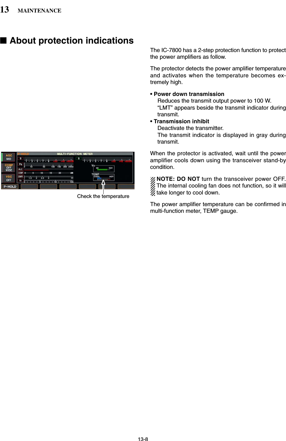
![13-4■SWR readingThe SWR meter indicates the SWR over the transmis-sion line in all modes.qPush [TUNER] to turn the antenna tuner OFF.wPush [METER] for 1 sec. to display multi-functionmeter.ePush [RTTY/PSK] once or twice to select RTTYmode.rPush [TRANSMIT].tRotate [RF PWR] clockwise past the 12 o’clock po-sition for more than 30 W output power.yRead the SWR on the SWR meter gage.uPush [EXIT/SET] to close multi-function meter.The built-in antenna tuner matches the transmitterto the antenna when the SWR is lower than 3 : 1.■Screen type and font selections3 types of screen images and 18 types of frequencyreadout indication fonts are available in the IC-7800.qPush [EXIT/SET] several times to close multi-func-tion screen, if necessary.wPush [F-7•SET] to select set mode menu screen.ePush [F-3•DISP] to enter display set mode.rPush [F-1•Y] or [F-2•Z] to select “Display Type”item when selecting the screen image, select “Dis-play Font” when selecting the frequency readout in-dication font.tRotate the main dial to select the desired screenimage or font.• Screen image is selectable from A, B and C.• Italic (1)/(2)/(3)/(4), Round (1)/(2)/(3), Shadow (1)/(2)/(3),Qubic (1)/(2)/(3)/(4) and IC-780 (1)/(2)/(3)/(4) are avail-able for the frequency readout font.yPush [EXIT/SET] twice to exit from display setmode.SID051015001044ALC 52V VD20dB11.5 23∞10 50 100 150 200 250POSWRCOMPAW159+20 +40 +60dBBetter than 1.5:1[RF PWR][RTTY/PSK][EXIT/SET][METER][TRANSMIT][TUNER]13 MAINTENANCE• Screen image example— type C](https://usermanual.wiki/ICOM-orporated/259000.Users-Manual-Part-5/User-Guide-397411-Page-30.png)
![13-5■Frequency calibration (approximate)A very accurate frequency counter is required to cali-brate the frequency of the transceiver. However, arough check may be performed by receiving radio sta-tion WWVH, or other standard frequency signals.CAUTION: The IC-7800 has been thoroughly ad-justed and checked at the factory before beingshipped. You should not calibrate frequencies, ex-cept for special reasons.qPush [SSB] to select USB mode.wPush [PBT CLEAR] for 1 sec. to clear the PBT set-ting and make sure that the RIT/∂TX function is notactivated.eSet the frequency to the standard frequency stationminus 1 kHz.• When receiving WWVH (15.00000 MHz) as a standardfrequency, set the operating frequency for14.99900 MHz.• Other standard frequency can also be used.rPush [EXIT/SET] several times to close a multi-function screen, if necessary.• Calibration marker item tPush [F-7•SET] to select set mode menu screen.yPush [F-5•OTHERS] to enter miscellaneous (oth-ers) set mode.uPush [F-1•Y] several times to select the “Calibra-tion Marker” item.iRotate the main dial clockwise to turn the calibra-tion marker ON.oPush [EXIT/SET] once to return to set mode menuscreen.!0 Push [F-2•ACC] to enter accessory set mode.!1 Push [F-2•Z] several times to select the “REF Ad-just” item.!2 Rotate the main dial to adjust for a zero beat withthe received standard signal as shown at left.• REF Adjust item • Zero beat means that two signals are exactly the samefrequency, resulting in a single tone being emitted.!3 Turn the calibration marker OFF in miscellaneous(others) set mode.!4 Push [EXIT/SET] twice to exit set mode.[F-1•Y] [F-2•ACC]/[F-2•Z][F-5•OTHERS][EXIT/SET] Main dial[F-7•SET]13MAINTENANCE](https://usermanual.wiki/ICOM-orporated/259000.Users-Manual-Part-5/User-Guide-397411-Page-31.png)
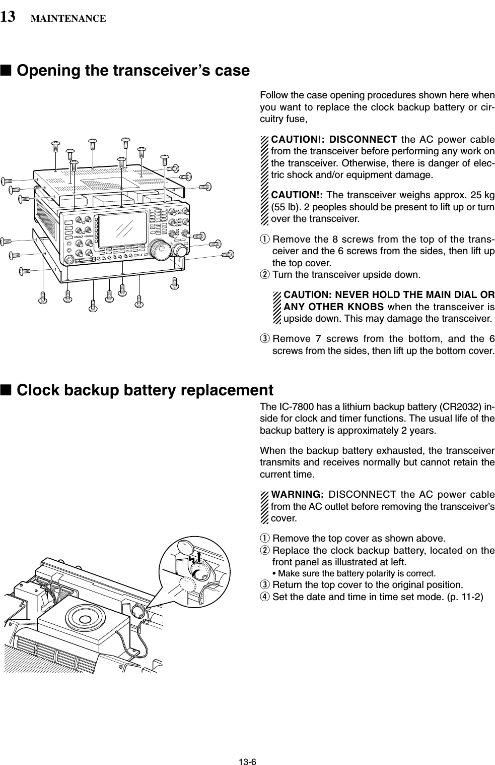
![13-7■Fuse replacementWhen no external DC output is available from [EXTDC] and ACC connectors, the internal fuse may bedamaged. Replace the fuse in this case.WARNING: DISCONNECT the AC power cablefrom the AC outlet before removing the transceiver’scover.qRemove the bottom cover as shown left.wReplace the damaged fuse with new, rated one(FGB 2 A) as shown at left.eReturn the bottom cover to the original position.■Resetting the CPUqTurn the main power switch on the rear panel ON.• Make sure the transceiver power is still OFF.wWhile pushing and holding [F-INP•ENT] and [MW],push [POWER] to turn power ON.• The internal CPU is reset.• The CPU start up and it takes approx. 5 sec.• The transceiver displays its initial VFO frequencieswhen resetting is complete.eCorrect the set mode settings after resetting, if de-sired.NOTE: Resetting CLEARS all programmed con-tents in memory channels and returns programmedvalues in set mode to default values.[F-INP•ENT][MW][POWER]13MAINTENANCEALL CLEAR](https://usermanual.wiki/ICOM-orporated/259000.Users-Manual-Part-5/User-Guide-397411-Page-33.png)
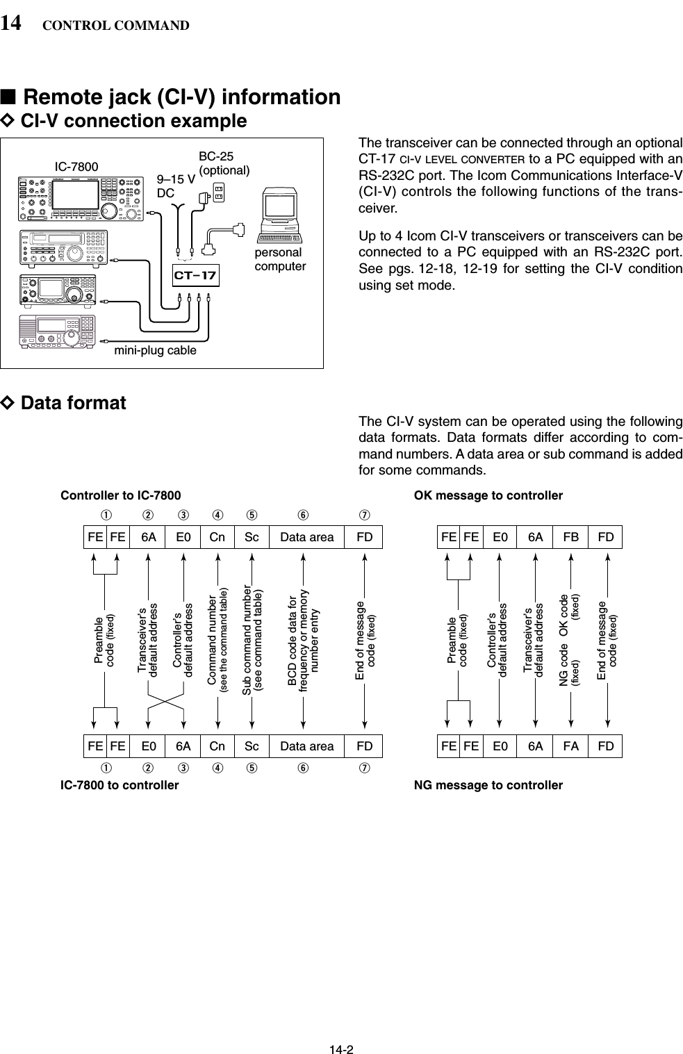
![14-3DCommand table14CONTROL COMMANDCommand Sub command Description00 — Send frequency data01 Same as Send mode datacommand 0602 — Read band edge frequencies03 — Read operating frequency04 — Read operating mode05 — Set operating frequency 06 00 Select LSB01 Select USB02 Select AM03 Select CW04 Select RTTY05 Select FM07 Select CW-R08 Select RTTY-R12 Select PSK13 Select PSK-R07 — Select VFO modeB0 Exchange main and sub bandsB1 Equalize main and sub bandsC0 Turn the dualwatch OFFC1 Turn the dualwatch OND0 Select main bandD1 Select sub band08 — Select memory mode0001–0101* Select memory channel*P1=0100, P2=010109 — Memory write0A — Memory to VFO0B — Memory clear0E 00 Scan stop01 Programmed/memory scan start02 Programmed scan start03 ∂F scan start12 Fine programmed scan start13 Fine ∂F scan start22 Memory scan start23 Select memory scan startA1–A7 Set ∂F scan span (A1=±5 kHz;A2=±10 kHz; A3=±20 kHz;A4=±50 kHz; A5=±100 kHz; A6=±500 kHz; A7=±1 MHz)B0 Set as non-select channelB1 Set as select channel (1=★1;2=★2; 3=★3; when no data com-mand is specified, the previouslyset number or “★1” is selected)B2 Set the number for select memoryscan (0=ALL; 1=★1; 2=★2; 3=★3)D0 Set scan resume OFFD3 Set scan resume ON0F 00 Turn the split function OFF01 Turn the split function ON10 00 Select 10 Hz (1 Hz) tuning step01 Select 100 Hz tuning step02 Select 1 kHz tuning step03 Select 5 kHz tuning step04 Select 9 kHz tuning step05 Select 10 kHz tuning step06 Select 12.5 kHz tuning step07 Select 20 kHz tuning step08 Select 25 kHz tuning stepCommand Sub command Description11 — Select/read attenuator (0=OFF;1=3 dB; 2=6 dB; 3=9 dB; 4=12 dB;5=15 dB; 6=18 dB; 7=21 dB)12 00 + RX ANT Select/read ANT1 selection(00=RX ANT OFF; 01=RX ANT ON)01 + RX ANT Select/read ANT2 selection(00=RX ANT OFF; 01=RX ANT ON)02 + RX ANT Select/read ANT3 selection(00=RX ANT OFF; 01=RX ANT ON)03 + RX ANT Select/read ANT4 selection(00=RX ANT OFF; 01=RX ANT ON)13 00 Announce with voice synthesizer01 (00=all data; 01=frequency and 02 S-meter level; 02=receive mode)14 01 + Level data [AF] level setting (0=max. CCW to255=max. CW)02 + Level data [RF] level setting (0=max. CCW to255=11 o’clock)03 + Level data [SQL] level setting (0=11 o’clock to255=max. CW)05 + Level data [APF] level setting(0=Pitch–550 Hz, 128=Pitch,255=Pitch+550 Hz)06 + Level data [NR] level setting (0=min. to255=max.)07 + Level data Inside [TWIN PBT] setting or IFshift setting (0=max. CCW,128=center, 255=max. CW)08 + Level data Outside [TWIN PBT] setting (0=max. CCW, 128=center,255=max. CW)09 + Level data [CW PITCH] setting (0=300 Hz,128=600 Hz, 255=900 Hz; 25 Hzsteps)0A + Level data [RF POWER] setting (0=max.CCW to 255=max. CW)0B + Level data [MIC] setting (0=max. CCW to255=max. CW)0C + Level data [KEY SPEED] setting (0=max.CCW to 255=max. CW)0D + Level data [NOTCH] setting (0=low freq. to255=high freq.)0E + Level data [COMP] setting (0=max. CCW to255=max. CW)0F + Level data [DELAY] setting (0=max. CCW to255=max. CW)11 + Level data [AGC] control setting (0=max.CCW to 255=max. CW)12 + Level data [NB] control setting (0=max. CCWto 255=max. CW)13 + Level data [DIGI-SEL] setting (0=max. CCWto 255=max. CW)14 + Level data [DRIVE] setting (0=max. CCW to255=max. CW)15 + Level data [MONI GAIN] setting (0=max.CCW to 255=max. CW)16 + Level data [VOX GAIN] setting (0=max.CCW to 255=max. CW)17 + Level data [ANTI VOX] setting (0=max. CCWto 255=max. CW)18 + Level data [CONTRAST] setting (0=max.CCW to 255=max. CW)19 + Level data [BRIGHT] setting (0=max. CCWto 255=max. CW)](https://usermanual.wiki/ICOM-orporated/259000.Users-Manual-Part-5/User-Guide-397411-Page-37.png)
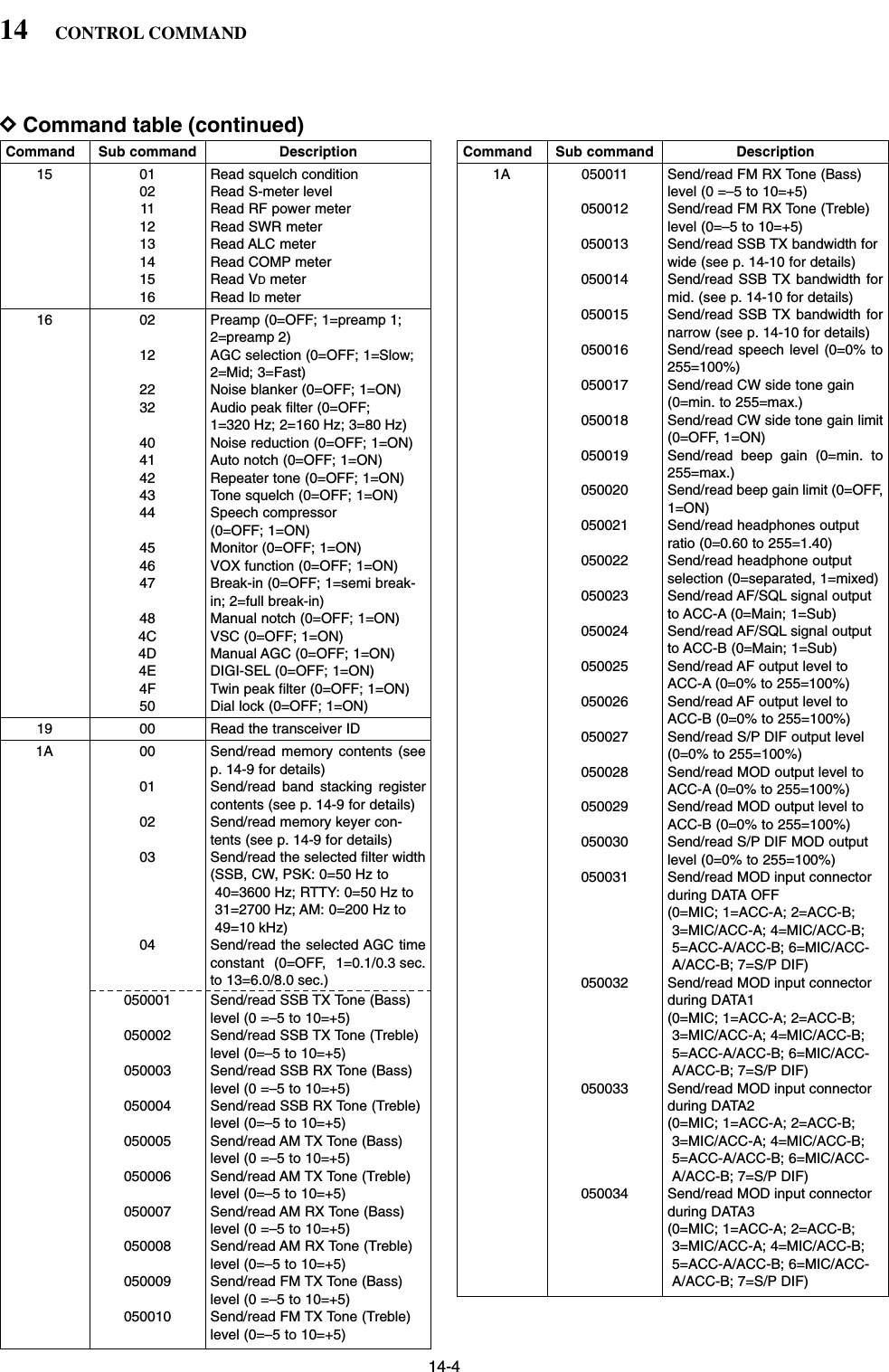
![14-914CONTROL COMMANDDTo send/read memory contentsWhen sending or reading memory contents, additionalcode as follows must be added to appoint the memorychannel.➥Additional code: 0000–0101 (0100=P1, 0101=P2)DBand stacking registerTo send or read the desired band stacking register’scontents, combined code of the frequency band andregister codes as follows are used. For example, when sending/reading the oldest con-tents in the 21 MHz band, the code “0703” is used.• Frequency band code • Register code DCodes for memory keyer contentsTo send or read the desired memory keyer contents,the channel and character codes as follows are used. • Channel code • Character’s code DCodes for memory name, openingmessage and clock 2 name contentsTo send or read the desired memory name settings,the character codes, instructed codes for memorykeyer contents as above, and follows are additionallyused.•Character’s code— Alphabetical characters•Character’s code— Symbols Character ASCII code Character ASCII codea–z 61–7A — —Code Frequency band Frequency range (unit: MHz)01 1.8 1.800000– 1.99999902 3.5 3.400000– 4.09999903 7 6.900000– 7.49999904 10 9.900000–10.49999905 14 13.900000–14.49999906 18 17.900000–18.49999907 21 20.900000–21.49999908 24 24.400000–25.09999909 28 28.000000–29.99999910 50 50.000000–54.00000012 GENE Other than aboveCode Registered number01 1 (latest)02 203 3 (oldest)Character ASCII code Description0–9 30–39 NumeralsA–Z 41–5A Alphabetical charactersspace 20 Word space / 2F Symbol? 3F Symbol, 2C Symbol. 2E Symbol^ 5E e.g., to send BT, enter ^4254✱2A Inserts contest number (can beused for 1 channel only)Code Channel number01 M102 M203 M304 M4Character ASCII code Character ASCII code!21#23$24%25&26¥5C?3F ” 22’27`60+2B–2D:3A;3B=3D<3C>3E ( 28)29[5B]5D{7B}7D|7C_5F–7E@](https://usermanual.wiki/ICOM-orporated/259000.Users-Manual-Part-5/User-Guide-397411-Page-43.png)
![15-4■Options•IC-PW1 HF/50MHzALL BAND1kW LINEAR AMPLIFIERFull-duty 1 kW linear amplifier including an automaticantenna tuner. Has automatic tuning and band selec-tion capability. Full break-in (QSK) operation is possi-ble. The amplifier/power supply unit and the remotecontrol unit are separated.*The IC-PW1 does not comply with European HarmonisedStandard regulations. Please do not use this equipmentwithin European countries.•SM-20 DESKTOP MICROPHONEUnidirectional, electret microphone for base stationoperation. Includes [UP]/[DOWN] switches and a lowcut function.•CT-17 CI-V LEVEL CONVERTERFor remote transceiver control using a PC. You canchange frequencies, operating mode, memory chan-nels, etc. (software is not included)•SP-20 EXTERNAL SPEAKER4 audio filters; headphone jack; can connect to 2transceivers.• Input impedance : 8 Ω• Max. input power : 5 W•HM-36 HAND MICROPHONEHand microphone equipped with [UP]/[DOWN] switch-es.15 SPECIFICATIONS AND OPTIONS](https://usermanual.wiki/ICOM-orporated/259000.Users-Manual-Part-5/User-Guide-397411-Page-48.png)