ICOM orporated 259000 Amateur HF Scanning Transceiver User Manual IC 7800 Eng
ICOM Incorporated Amateur HF Scanning Transceiver IC 7800 Eng
Contents
- 1. Users Manual Part 1
- 2. Users Manual Part 2
- 3. Users Manual Part 3
- 4. Users Manual Part 4
- 5. Users Manual Part 5
Users Manual Part 5

12-1
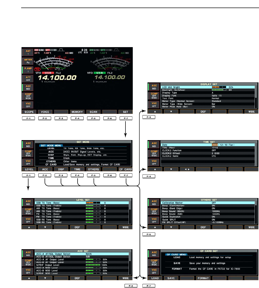
SET MODE Section 12
■Set mode description ………………………………………………… 12-2
DSet mode operation ………………………………………………… 12-2
DScreen arrangement ……………………………………………… 12-3
■Level set mode ………………………………………………………… 12-4
■ACC set mode ………………………………………………………… 12-6
■Display set mode …………………………………………………… 12-11
■Miscellaneous (Others) set mode ………………………………… 12-13
■CF card set menu …………………………………………………… 12-21
DCF card set screen arrangement ……………………………… 12-21
DSave option set mode …………………………………………… 12-21
DLoad option set mode …………………………………………… 12-22
■File saving …………………………………………………………… 12-23
■File loading …………………………………………………………… 12-24
■Changing the file name ……………………………………………… 12-25
■Deleting a file ………………………………………………………… 12-26
■Formatting the CF card ……………………………………………… 12-26
12-2
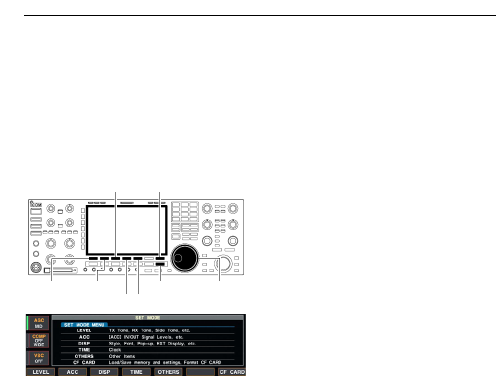
■Set mode description
Set mode is used for programming infrequently
changed values or conditions of functions. The IC-
7800 has a level set mode, display set mode, timer set
mode, accessory set mode and miscellaneous (others)
set mode.
DSet mode operation
qPush [EXIT/SET] several times to close a multi-
function screen, if necessary.
wPush [F-7•SET] to select set mode menu screen.
• Pushing and holding [EXIT/SET] for 1 sec. also selects
set mode menu screen.
ePush [F-1•LEVEL], [F-2•ACC], [F-3•DISP],
[F-4•TIME], [F-5•OTHERS] or [F-7•CF CARD] to
enter the desired set mode.
rFor level, accessory, display and miscellaneous
(others) set mode, push [F-7•WIDE] to toggle wide
and normal screen.
tPush [F-1•Y] or [F-2•Z] to select the desired item,
then rotate main dial to adjust/select the desired
value or condition.
• Pushing [F-3•Ω≈] operation may be necessary for
some items.
yPush [EXIT/SET] twice to exit set mode.
[F-1•LEVEL] [F-2•ACC]
[F-3•DISP]
[F-5•OTHERS][F-4•TIME]
[EXIT/SET] Main dial
[F-7•CF CARD]
12 SET MODE
12-3
12
SET MODE
DScreen arrangement
• Set mode menu screen (p. 12-2)
• Level set mode (p. 12-4)
• ACC set mode (p. 12-6)
• Time set mode (p. 11-2)
• Display set mode (p. 12-11)
• Miscellaneous (Others) set mode (p. 12-13)
• CF card set menu (p. 12-21)
12-4
12 SET MODE
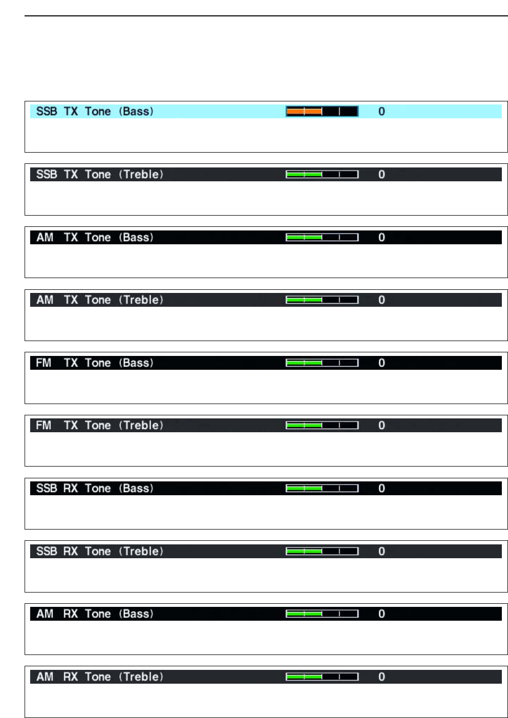
■Level set mode
Sets the bass level of the transmit audio tone in SSB
mode from –5 to +5. (default: 0)
Sets the treble level of the transmit audio tone in SSB
mode from –5 to +5. (default: 0)
Sets the bass level of the transmit audio tone in AM
mode from –5 to +5. (default: 0)
Sets the treble level of the transmit audio tone in AM
mode from –5 to +5. (default: 0)
Sets the bass level of the transmit audio tone in FM
mode from –5 to +5. (default: 0)
Sets the treble level of the transmit audio tone in FM
mode from –5 to +5. (default: 0)
Sets the bass level of the receive audio tone in SSB
mode from –5 to +5. (default: 0)
Sets the treble level of the receive audio tone in SSB
mode from –5 to +5. (default: 0)
Sets the bass level of the receive audio tone in AM
mode from –5 to +5. (default: 0)
Sets the treble level of the receive audio tone in AM
mode from –5 to +5. (default: 0)
12-5
12
SET MODE
■Level set mode (continued)
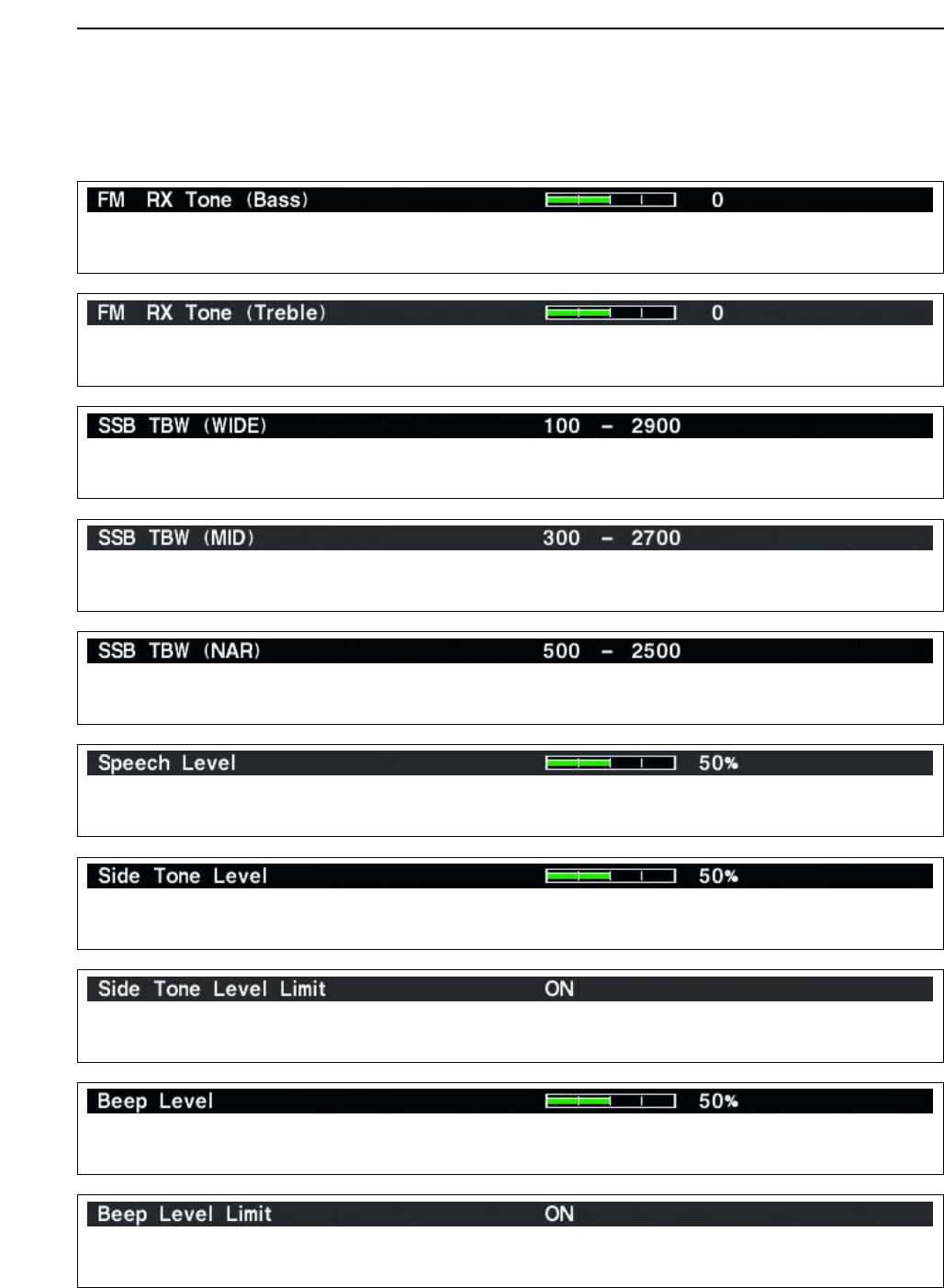
Sets the bass level of the receive audio tone in FM
mode from –5 to +5. (default: 0)
Sets the treble level of the receive audio tone in FM
mode from –5 to +5. (default: 0)
Sets the transmission passband width for wide setting
by selecting the lower and higher frequencies.
Lower freq. : 100 (default), 300 and 500 Hz
Higher freq.: 2500, 2700 and 2900 Hz (default)
Sets the transmission passband width for middle set-
ting by selecting the lower and higher frequencies.
Lower freq. : 100, 300 (default) and 500 Hz
Higher freq.: 2500, 2700 (default) and 2900 Hz
Sets the transmission passband width for narrow set-
ting by selecting the lower and higher frequencies.
Lower freq. : 100, 300 and 500 Hz (default)
Higher freq.: 2500 (default), 2700 and 2900 Hz
Sets the voice synthesizer audio output level from 0 to
100% in 1% steps. (default: 50%)
Sets the side tone output level from 0 to 100% in 1%
steps. (default: 50%)
Turns the side tone output level limiting capability from
ON and OFF. (default: ON)
Sets the key-touch beep output level from 0 to 100%
in 1% steps. (default: 50%)
Turns the key-touch beep output level limiting capa-
bility from ON and OFF. (default: ON)
12-6
12 SET MODE
■Level set mode (continued)
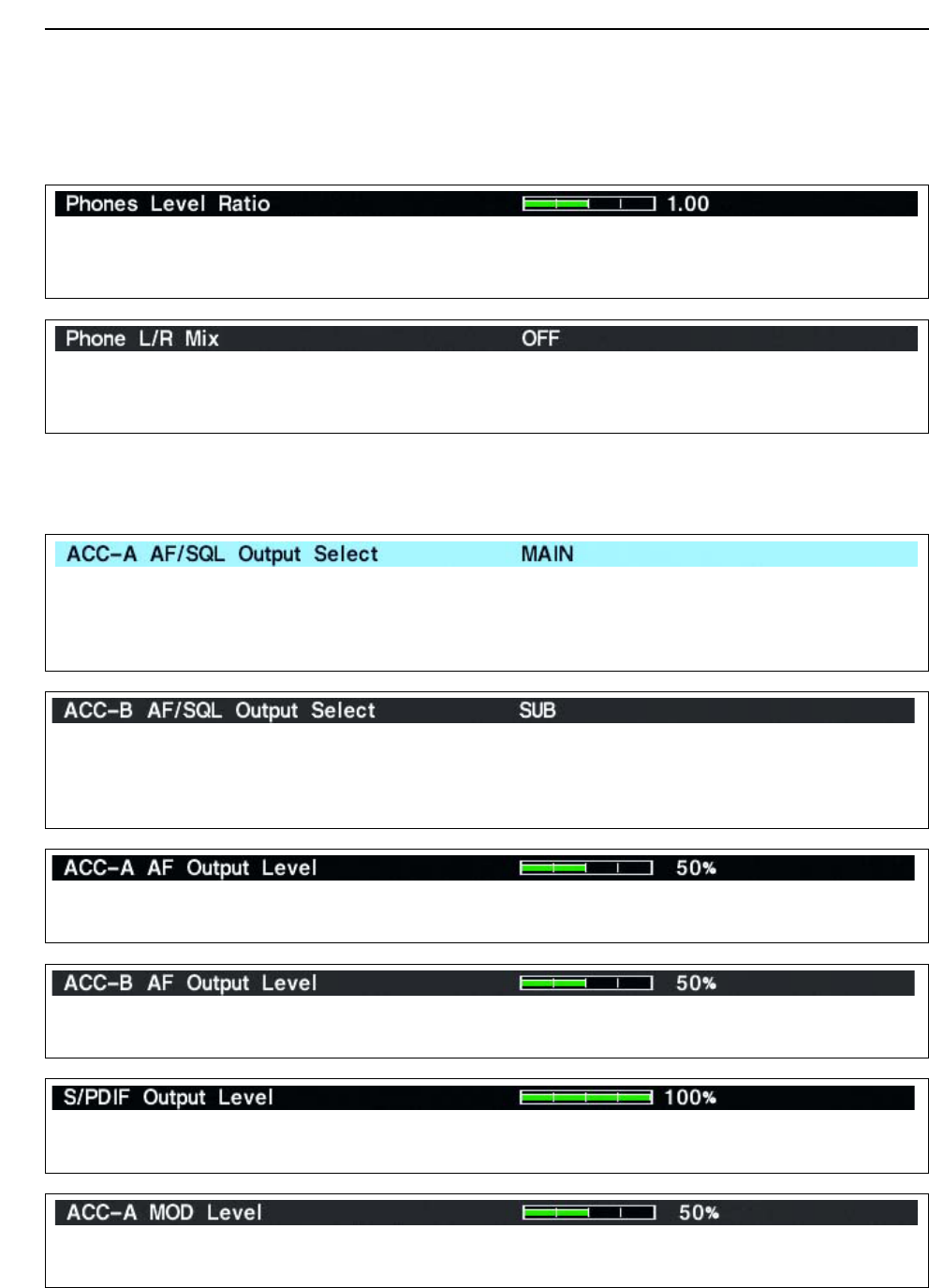
Sets the ratio for audio output level from the head-
phone toward to the internal speaker within 0.60 to
1.40 range in 0.01 steps. (default: 1.00)
Selects the headphone audio output. • OFF : Outputs the main band’s audio from the left,
and sub band’s audio from the right. (default)
• ON : Outputs the mixed audio.
Selects the desired band for the audio and squelch
signals output from [ACC1–A] (Audio: pin 5, Squelch:
pin 6) from MAIN and SUB.
• MAIN : Main band’s AF and squelch signals are
output from [ACC1–A]. (default)
• SUB : Sub band’s AF and squelch signals are out-
put from [ACC1–A].
Selects the desired band for the audio and squelch
signals output from [ACC1–B] (Audio: pin 5, Squelch:
pin 6) from MAIN and SUB.
• MAIN : Main band’s AF and squelch signals are
output from [ACC1–A].
• SUB : Sub band’s AF and squelch signals are out-
put from [ACC1–A]. (default)
Sets the desired audio output level, output from
[ACC1–A], within 0 to 100% in 1% steps.
• Outputs approx. 200 mV at 50% (default) setting.
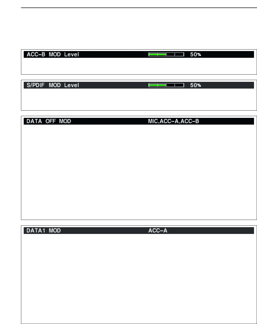
Sets the desired audio output level, output from
[ACC1–B], within 0 to 100% in 1% steps.
• Outputs approx. 200 mV at 50% (default) setting.
Sets the desired output level of [S/P DIF], within 0 to
100% in 1% steps. (default: 100%)
Sets the desired audio input level for modulation from
[ACC1–A].
• Approx. 100 mV at 50% (default) setting.
■ACC set mode
12-7
12
SET MODE
Sets the desired audio input level for modulation from
[ACC1–B].
• Approx. 100 mV at 50% (default) setting.
Sets the desired input level for modulation from
[S/P DIF], within 0 to 100% in 1% steps.
(default: 50%)
■ACC set mode (continued)
Selects the desired connector(s) for modulation input
when data mode is not in use.
• MIC : Use the signals from [MIC].
• ACC-A : Use the signals from [ACC1–A]
(pin 4).
• ACC-B : Use the signals from [ACC1–B]
(pin 4).
• MIC,ACC-A : Use the signals from [MIC] and
[ACC1–A] (pin 4).
• MIC,ACC-B : Use the signals from [MIC] and
[ACC1–B] (pin 4).
• ACC-A,ACC–B : Use the signals from [ACC1–A]
and [ACC1–B] (pin 4).
• MIC,ACC-A,ACC–B
: Use the signals from [MIC],
[ACC1–A] and [ACC1–B] (pin 4).
(default)
• S/P DIF : Use the signals from [S/P DIF].
Selects the desired connector(s) for modulation input
when data 1 mode (D1) is in use.
• MIC : Use the signals from [MIC].
• ACC-A : Use the signals from [ACC1–A]
(pin 4). (default)
• ACC-B : Use the signals from [ACC1–B]
(pin 4).
• MIC,ACC-A : Use the signals from [MIC] and
[ACC1–A] (pin 4).
• MIC,ACC-B : Use the signals from [MIC] and
[ACC1–B] (pin 4).
• ACC-A,ACC–B : Use the signals from [ACC1–A]
and [ACC1–B] (pin 4).
• MIC,ACC-A,ACC–B
: Use the signals from [MIC],
[ACC1–A] and [ACC1–B] (pin 4).
• S/P DIF : Use the signals from [S/P DIF].
12-8
12 SET MODE
■ACC set mode (continued)
Selects the desired band for the operating frequency
band control signal output from (pin 4).
• MAIN : Outputs the band signal displayed in main
readout.
• SUB : Outputs the band signal displayed in sub
readout.
• TX : Outputs the band signal, that can be trans-
mitted. (default)
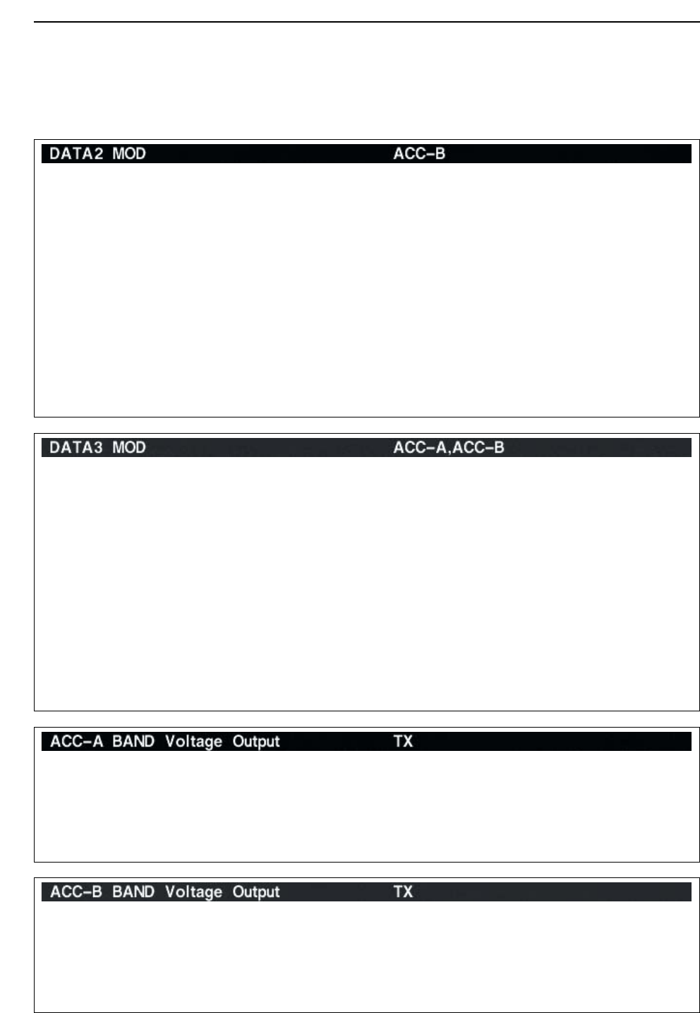
Selects the desired connector(s) for modulation input
when data 2 mode (D2) is in use.
• MIC : Use the signals from [MIC].
• ACC-A : Use the signals from [ACC1–A]
(pin 4).
• ACC-B : Use the signals from [ACC1–B]
(pin 4). (default)
• MIC,ACC-A : Use the signals from [MIC] and
[ACC1–A] (pin 4).
• MIC,ACC-B : Use the signals from [MIC] and
[ACC1–B] (pin 4).
• ACC-A,ACC–B : Use the signals from [ACC1–A]
and [ACC1–B] (pin 4).
• MIC,ACC-A,ACC–B
: Use the signals from [MIC],
[ACC1–A] and [ACC1–B] (pin 4).
• S/P DIF : Use the signals from [S/P DIF].
Selects the desired connector(s) for modulation input
when data 3 mode (D3) is in use.
• MIC : Use the signals from [MIC].
• ACC-A : Use the signals from [ACC1–A]
(pin 4).
• ACC-B : Use the signals from [ACC1–B]
(pin 4).
• MIC,ACC-A : Use the signals from [MIC] and
[ACC1–A] (pin 4).
• MIC,ACC-B : Use the signals from [MIC] and
[ACC1–B] (pin 4).
• ACC-A,ACC–B : Use the signals from [ACC1–A]
and [ACC1–B] (pin 4). (default)
• MIC,ACC-A,ACC–B
: Use the signals from [MIC],
[ACC1–A] and [ACC1–B] (pin 4).
• S/P DIF : Use the signals from [S/P DIF].
Selects the desired band for the operating frequency
band control signal output from [ACC2–A] (pin 4).
• MAIN : Outputs the band signal displayed in main
readout.
• SUB : Outputs the band signal displayed in sub
readout.
• TX : Outputs the band signal, that can be trans-
mitted. (default)
12-9
12
SET MODE
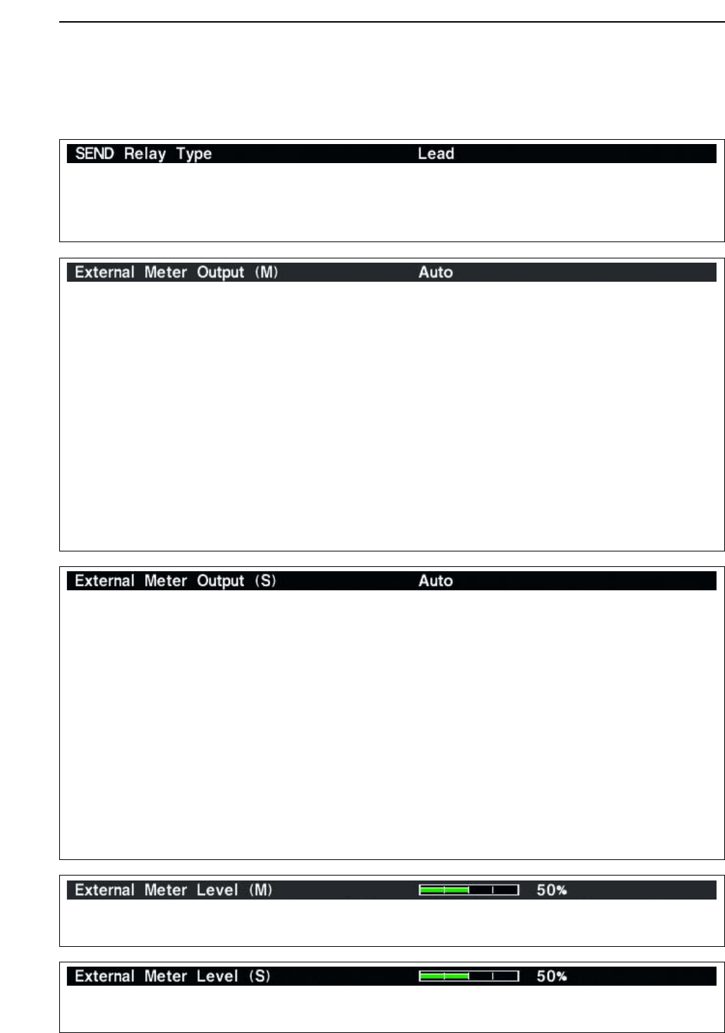
Selects the switching relay type for [RELAY] from
Lead and MOS-FET.
Select the suitable relay type when connecting a non-
Icom linear amplifier.
• Lead : Use mechanical relay.
(16 V DC/0.5 A max.; default)
• MOS-FET: Use semiconductor type relay.
(200 mA/250 V max.)
■ACC set mode (continued)
Selects the desired item for an external meter indica-
tion (main readout).
• Auto : Outputs the receiving signal strength level
during receive, and outputs the selected
content’s level, selected with [METER],
during transmit. (default)
• S(MAIN) : Outputs the receiving signal strength level
during receive.
• Po : Outputs the transmitting power level dur-
ing transmit.
• SWR : Outputs the VSWR level during transmit.
• ALC : Outputs the ALC level during transmit.
• COMP : Outputs the compression level during
transmit.
•V
D: Outputs the drain’s terminal voltage of the
final FETs.
•I
D: Outputs the drain’s current of the final
FETs.
Selects the desired item for an external meter indica-
tion (sub readout).
• Auto : Outputs the receiving signal strength level
during receive, and outputs the selected
content’s level, selected with [METER],
during transmit. (default)
• S(MAIN) : Outputs the receiving signal strength level
during receive.
• Po : Outputs the transmitting power level dur-
ing transmit.
• SWR : Outputs the VSWR level during transmit.
• ALC : Outputs the ALC level during transmit.
• COMP : Outputs the compression level during
transmit.
•V
D: Outputs the drain’s terminal voltage of the
final FETs.
•I
D: Outputs the drain’s current of the final
FETs.
Sets the output level for an external meter indication
(main readout) with in 0 to 100% range in 1% steps.
• Approx. 2.5 V at 50% (default) setting for full-scale indica-
tion. (4.7 kΩimpedance)
Sets the output level for an external meter indication
(sub readout) with in 0 to 100% range in 1% steps.
• Approx. 2.5 V at 50% (default) setting for full-scale indica-
tion. (4.7 kΩimpedance)
12-10
12 SET MODE
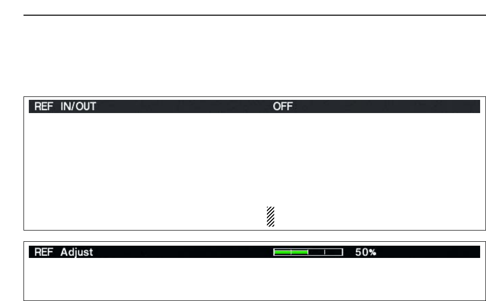
Adjusts the internal reference signal frequency within
0 to 100% range in 1% steps during frequency cali-
bration. (default: 50%)
Selects the transceiver’s reference signal condition
from IN, OFF and OUT.
• IN : Use an external reference signal for the IC-
7800.
• OFF : Not input/output the reference signal.
(default)
• OUT : Outputs the IC-7800 reference signal to ex-
ternally connected equipment(s) for their ref-
erence.
NOTE: When the applied reference signal has off-
frequency, the IC-7800 may not work properly.
■ACC set mode (continued)
12-11
12
SET MODE
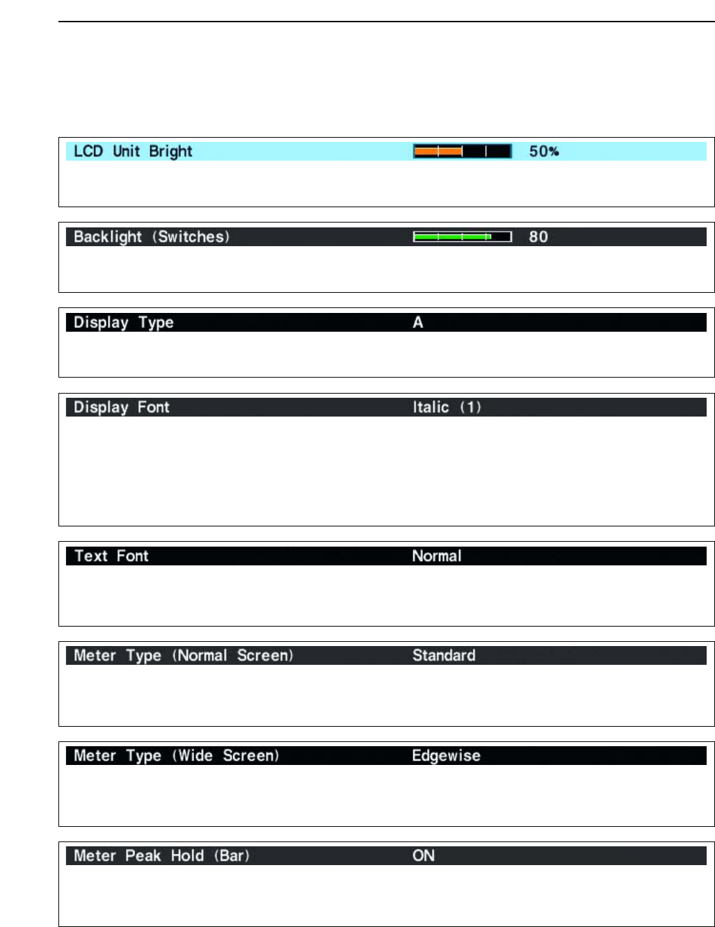
Adjusts the LCD unit brightness within 0 (dark) to
100% (bright) range in 1% steps. (default: 50%)
Adjusts the switch indicators brightness within 1 (dark)
to 100 (bright) range in 1 steps. (default: 80)
Selects the desired display type from A, B and C.
(default: A)
Selects the desired font for frequency readout from
Italic (1), Italic (2), Italic (3), Italic (4), Round (1),
Round (2), Round (3), Shadow (1), Shadow (2),
Shadow (3), Qubic (1), Qubic (2), Qubic (3), Qubic
(4), IC-780 (1), IC-780 (2), IC-780 (3) and IC-780 (4).
(default: Italic (1))
Selects the desired font for the indications other than
frequency readout from Normal and Slim.
(default: Normal)
■Display set mode
Selects the desired S/RF meter type during normal
screen indication from Standard, Edgewise and Bar.
(default: Standard)
Selects the desired S/RF meter type during wide
screen or mini scope indication from Edgewise and
Bar. (default: Edgewise)
Turns the meter peak hold function ON and OFF.
(default: ON)
This function is used for the bar meter only.
12-12
12 SET MODE
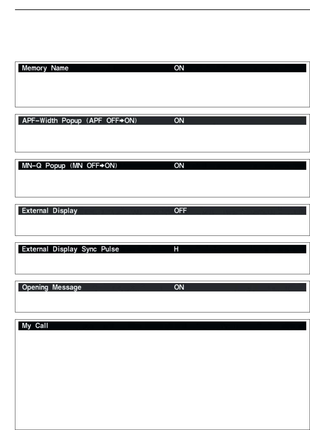
Sets the desired 10-character text, such as your call
sign, name, etc.
The set text is indicated in the opening screen.
Capital letters, small letters, numerals, some symbols
(– / . @) and spaces can be used.
zPush [F-5•EDIT] to select the name edit condition.
• The 1st character and cursor blink.
xPush [ABC], [abc], [123] or [Symbol] to select the
character group, then rotate the main dial to select
the character.
• Push [ABC] or [abc] to toggle capital and small letters.
• Push [123] or [Symbol] to toggle numerals and sym-
bols.
• Push [F-1•Ω] or [F-2•≈] for cursor movement.
• Push [F-3•DEL] to delete the selected character.
• Push [F-4•SPACE] to input a space.
• Pushing the transceiver’s keypad, [0]–[9], can also
enter numerals.
cPush [EXIT/SET] to set the name.
Turns the pop-up indication capability when the filter
width for the APF is changed from ON and OFF.
(default: ON)
Turns the pop-up indication capability when the notch
filter width is changed from ON and OFF.
(default: ON)
Select “ON” when the external display is connected.
(default: OFF)
• At least 800×600 pixel resolution is required for the dis-
play.
Selects the suitable pulse level for the connected ex-
ternal display from H and L. (default: H)
Turns the opening message screen indication capa-
bility ON and OFF. (default: ON)
Sets the memory name indication, during memory
mode operation, ON and OFF. (default: ON)
• ON : The programmed memory name is displayed
above the frequency indication.
• OFF : No memory name is displayed even a mem-
ory name is programmed.
■Display set mode (continued)
12-13
12
SET MODE
■Miscellaneous (Others) set mode
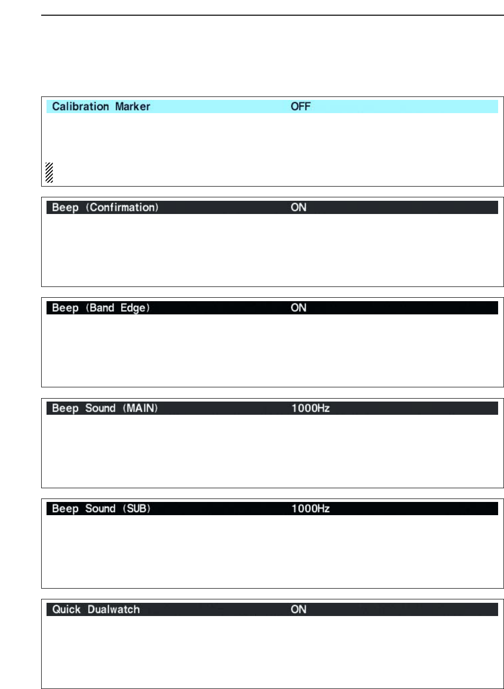
This item is used for a simple frequency check of the
transceiver. (default: OFF)
See p. 13-5 for calibration procedure.
NOTE: Turn the calibration marker OFF after
checking the frequency of the transceiver.
A beep sounds each time a switch is pushed to con-
firm it. This function can be turned OFF for silent op-
eration. (default: ON)
The beep output level can be set in level set mode.
(p. 12-5)
A beep sounds when an operating frequency enters
or exits an amateur band. This functions independent
of the confirmation beep setting (above). (default: ON)
The beep output level can be set in level set mode.
(p. 12-5)
Sets the desired key-touch beep sound frequency
during main readout operation within 500 to 2000 Hz
in 10 Hz steps. (default: 1000 Hz)
Set the different frequency from “Beep Sound (SUB)”
as below to distinguish between main and sub.
Sets the desired key-touch beep sound frequency
during sub readout operation within 500 to 2000 Hz in
10 Hz steps. (default: 1000 Hz)
Set the different frequency from “Beep Sound (MAIN)”
as above to distinguish between main and sub.
When this item is set to ON, pushing [DUALWATCH]
for 1 sec. sets the sub readout frequency to the main
readout frequency and activates dualwatch operation.
(default: ON)
See p. 5-16 for details.
12-14
12 SET MODE
■Miscellaneous (Others) set mode (continued)
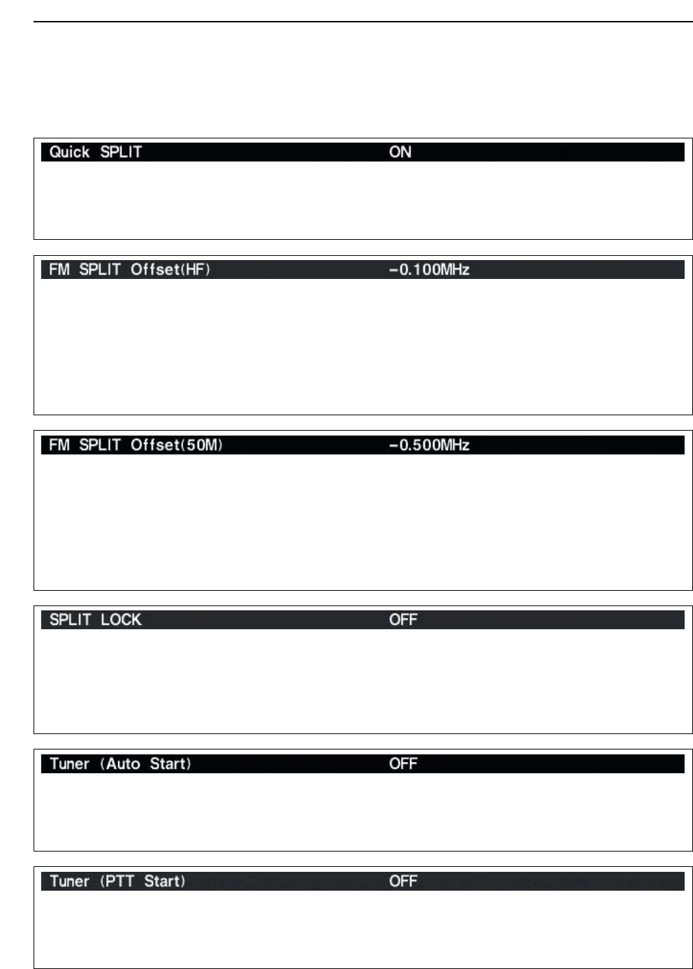
Sets the offset (difference between transmit and re-
ceive frequencies) for the quick split function. How-
ever, this setting is used for HF bands in FM mode
only and is used to input the repeater offset for an HF
band.
The offset frequency can be set from –9.999 MHz to
+9.999 MHz in 1 kHz steps. (default: –0.100 MHz)
Sets the offset (difference between transmit and re-
ceive frequencies) for the quick split function. How-
ever, this setting is used for 50 MHz band FM mode
only, and is used to input the repeater offset for the
50 MHz band.
The offset frequency can be set from –9.999 MHz to
+9.999 MHz in 1 kHz steps. (default: –0.500 MHz)
When this item is ON, the main dial can be used to
adjust the transmit frequency while pushing [XFC]
even while the lock function is activated.
(default: OFF)
See pgs. 6-6, 6-7 for split frequency operation details.
The internal antenna tuner has an automatic start ca-
pability which starts tuning if the SWR is higher than
1.5–3:1.
• OFF : The tuner remains OFF even when the SWR
is poor (1.5–3:1). (default)
• ON : Automatic tune starts even when the tuner is
turned OFF during HF bands operation.
Tuning of the internal antenna tuner can be started
automatically at the moment the PTT is pushed after
the operating frequency is changed (more than 1%
from last-tuned frequency). (default: OFF)
When this item is set to ON, pushing [SPLIT] for 1
sec. sets the sub readout frequency to the main read-
out frequency and activates split operation.
(default: ON)
See p. 6-7 for details.
12-15
12
SET MODE
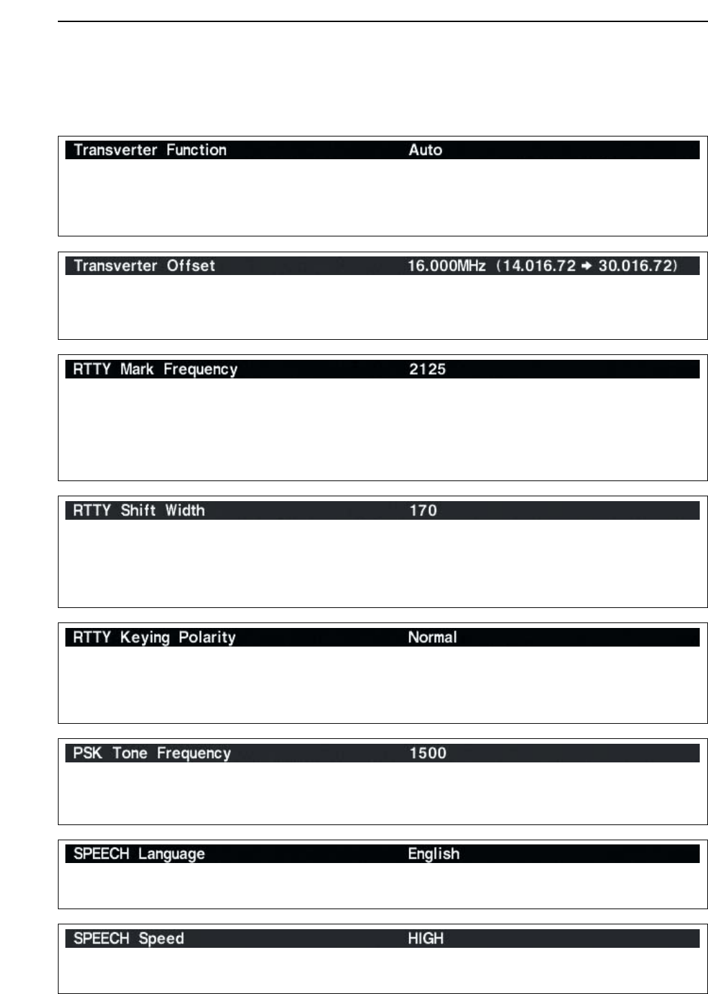
Selects the transverter operation condition from Auto
and ON. (default: Auto)
• ON : Turn the transverter operation ON.
• Auto : The transceiver turns into transverter opera-
tion condition when 2 to 13.8 V DC is applied
to [ACC2–A/B] pin 6.
Sets the desired offset frequency for the transverter
operation within 0.000 to 99.999 MHz in 1 kHz steps.
(default: 16.000 MHz)
■Miscellaneous (Others) set mode (continued)
Selects the RTTY mark frequency. RTTY mark fre-
quency is switched between 1275, 1615 and
2125 Hz. (default: 2125 Hz)
2125 Hz is automatically selected when the internal
RTTY decoder is used.
Selects the RTTY shift width. There are 3 selectable
values: 170, 200 and 425 Hz. (default: 170 Hz)
170 Hz is automatically selected when the internal
RTTY decoder is used.
Selects the RTTY keying polarity. Normal or reverse
keying polarity can be selected.
(default: Normal)
When reverse polarity is selected, Mark and Space
are reversed.
• Normal : Key open/close = Mark/Space
• Reverse : Key open/close = Space/Mark
Selects the desired PSK tone frequency for the PSK
reception from 1000, 1500 and 2000 Hz.
(default: 1500 Hz)
Selects the speech language from English and Japan-
ese. (default: English)
Selects the speech speed from HIGH (faster) and
LOW (slower). (default: HIGH)
12-16
12 SET MODE
■Miscellaneous (Others) set mode (continued)
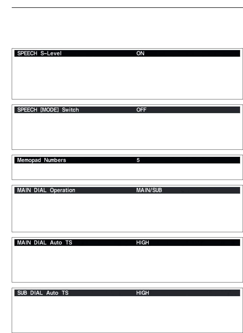
Selects the main dial function from MAIN and
MAIN/SUB. (default: MAIN/SUB)
• MAIN : The main dial functions only when ac-
cessing to main readout.
• MAIN/SUB : The main dial functions when access-
ing to main readout, as well as when
accessing to sub readout with [SUB]
switch operation.
Sets the auto tuning step function for the main dial.
When rotating the main dial rapidly, the tuning step
automatically changes several times as selected.
There are 2 type of auto tuning steps: HIGH (Fastest)
and LOW (Faster). (default: HIGH)
• HIGH : Auto tuning step is turned ON. Fastest tun-
ing step during rapid rotation. (default)
• LOW : Auto tuning step is turned ON. Faster tun-
ing step during rapid rotation.
• OFF : Auto tuning step is turned OFF.
Sets the auto tuning step function for the sub dial.
When rotating the sub dial rapidly, the tuning step au-
tomatically changes several times as selected.
There are 2 type of auto tuning steps: HIGH (Fastest)
and LOW (Faster). (default: HIGH)
• HIGH : Auto tuning step is turned ON. Fastest tun-
ing step during rapid rotation. (default)
• LOW : Auto tuning step is turned ON. Faster tun-
ing step during rapid rotation.
• OFF : Auto tuning step is turned OFF.
Sets the number of memo pad channels available. 5
or 10 memo pads can be set. (default: 5)
The IC-7800 speech processor has frequency, mode
and signal level announcement. Signal level an-
nouncement can be deactivated if desired.
(default: ON)
When “OFF” is selected, the signal level is not an-
nounced.
Turns the operating mode speech capability when a
mode switch is pushed from ON and OFF.
(default: OFF)
When “ON” is selected, the selected operating mode
is announced when a mode switch is pushed.
12-17
12
SET MODE
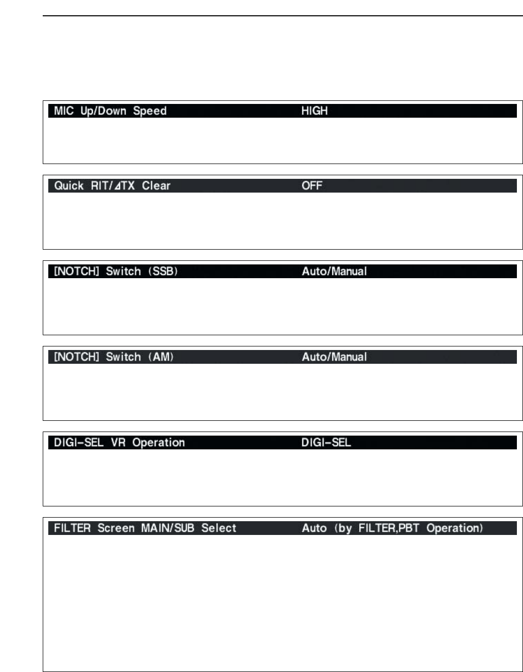
Selects [DIGI-SEL] control function from DIGI-SEL
and APF.
• DIGI-SEL : [DIGI-SEL] control functions as the digi-
tal selector operation. (default)
• APF : [DIGI-SEL] control functions as the
audio peak filter adjustment.
Sets the rate at which frequencies are scanned when
the microphone [UP]/[DN] switches are pushed and
held. High or low can be selected.
• HIGH : High speed (default; 50 tuning steps/sec.)
• LOW : Low speed (25 tuning steps/sec.)
Selects the RIT/∂TX frequency clearing instruction
with the [CLEAR] switch.
• ON : Clears the RIT/∂TX frequency when [CLEAR]
is pushed momentarily.
• OFF : Clears the RIT/∂TX frequency when [CLEAR]
is pushed for 1 sec. (default)
Selects usable notch function for SSB mode opera-
tion from Auto, Manual and Auto/Manual.
• Auto : The auto notch can only be used.
• Manual : The manual notch can only be used.
• Auto/Manual : Both the auto and manual notch can
be used. (default)
Selects usable notch function for AM mode operation
from Auto, Manual and Auto/Manual.
• Auto : The auto notch can only be used.
• Manual : The manual notch can only be used.
• Auto/Manual : Both the auto and manual notch can
be used. (default)
■Miscellaneous (Others) set mode (continued)
Selects filter set screen indication condition from Fix
and Auto (by FILTER,PBT Operation).
• Fix : When filter screen accessed with the main
band’s [FILTER] switch, the screen shows
main band’s filter width and PBT conditions
only; when filter set screen accessed with the
sub band’s [FILTER] switch, the screen shows
sub band’s filter width and PBT conditions only.
• Auto (by FILTER,PBT Operation)
: Filter set screen indication can be switched be-
tween main and sub bands filter width and PBT
conditions when either band’s [FILTER] switch
or [TWIN PBT] control is operated. (default)
12-18
12 SET MODE
Selects the displayed frequency shift function from
ON and OFF. (default: OFF)
When this function is activated, the receiving signal
can be kept to receive even when the operating mode
is changed between SSB and CW.
The frequency shifting value may differ according
to the CW pitch setting.
• ON : The displayed frequency shifts when the op-
erating mode is changed between SSB and
CW.
• OFF : The displayed frequency does not shift.
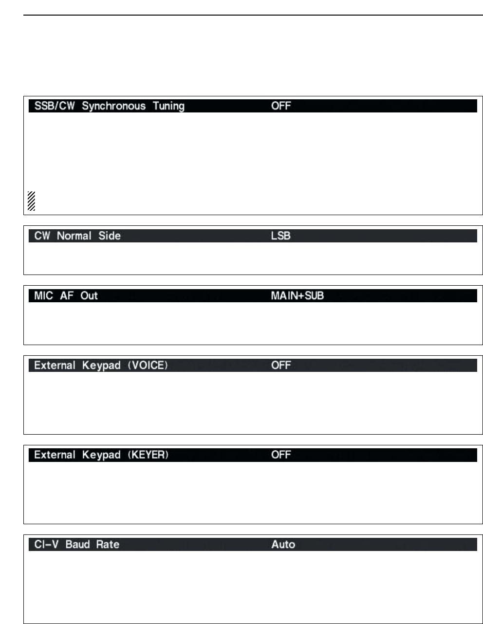
Selects the carrier point of CW mode from LSB and
USB. (default: LSB)
Selects the desired band(s) for audio output from
[MIC] connector (pin 8) from MAIN+SUB and SUB.
(default: MAIN+SUB)
• MAIN+SUB : Outputs both main and sub bands
audio.
• SUB : Outputs sub band audio only.
Sets the external keypad for voice memory transmis-
sion capability ON and OFF.
See page 2-6 for the equivalent circuit of an external
keypad and connection.
• ON : Pushing one of external keypad switches,
transmits the desired voice memory contents
during a phone mode operation.
• OFF : External keypad does not function. (default)
Sets the external keypad for keyer memory transmis-
sion capability ON and OFF.
See page 2-6 for the equivalent circuit of an external
keypad and connection.
• ON : Pushing one of external keypad switches,
transmits the desired keyer memory contents
during CW mode operation.
• OFF : External keypad does not function. (default)
sets the data transfer rate. 300, 1200, 4800, 9600,
19200 bps and “Auto” are available. (default: Auto)
When “Auto” is selected, the baud rate is automati-
cally set according to the connected controller or re-
mote controller.
■Miscellaneous (Others) set mode (continued)
12-19
12
SET MODE
■Miscellaneous (Others) set mode (continued)
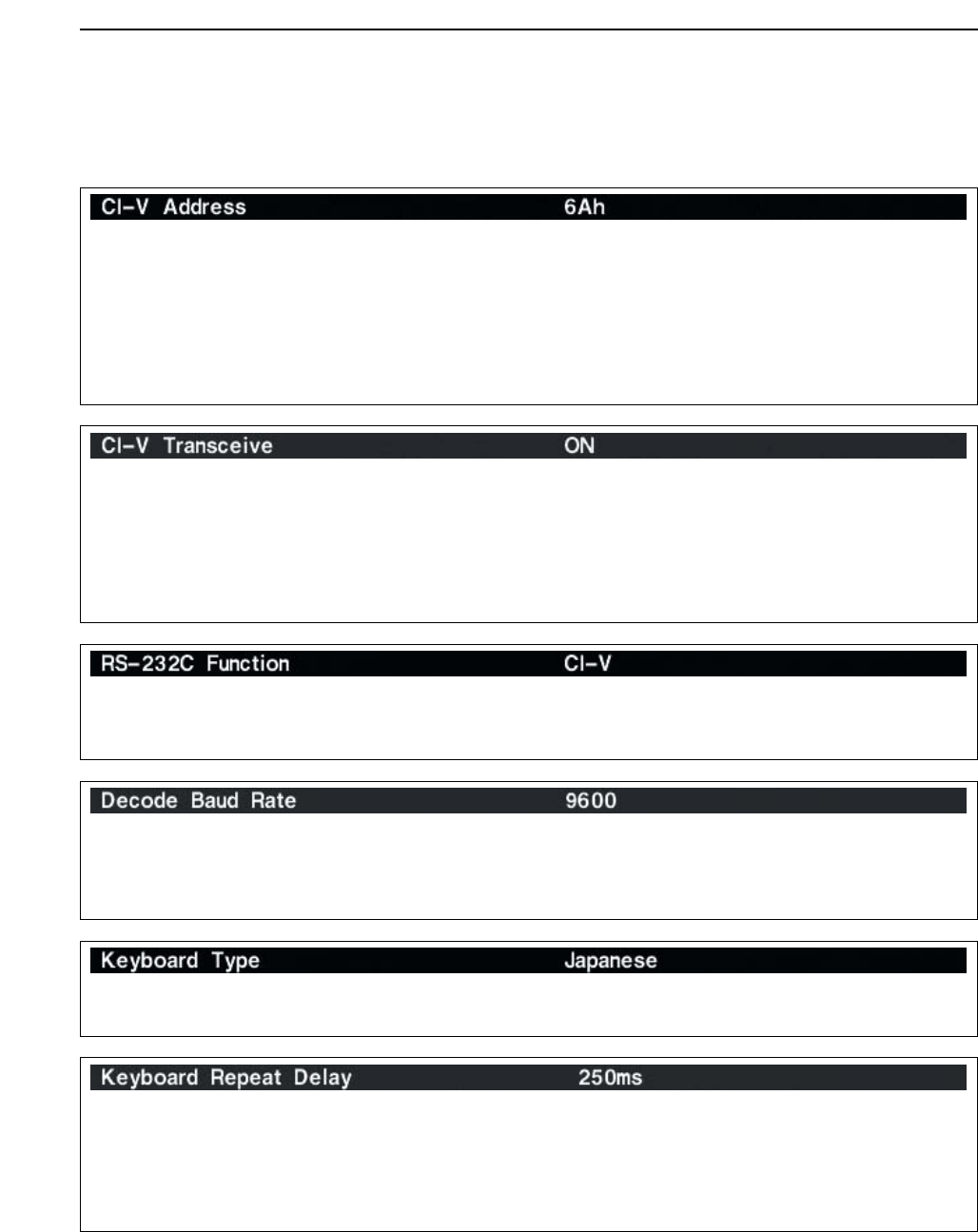
Transceive operation is possible with the IC-7800
connected to other Icom HF transceivers or receivers.
When “ON” is selected, changing the frequency, op-
erating mode, etc. on the IC-7800 automatically
changes those of connected transceivers (or re-
ceivers) and vice versa.
Select [RS-232C] connector output data format from
CI-V and Decode.
• CI-V : Outputs data in CI-V format. (default)
• Decode : Outputs decoded contents in ASCII code
format.
Selects data transmission speed (Baud rate) when
“Decode” is selected in “RS-232C Function” above
from 300, 1200, 4800, 9600 and 19200 bps.
(default: 9600)
Selects the connected keyboard type from Japanese
and English. (default: Japanese)
Sets the time period for delay within 100 to
1000 msec. in 50 msec. steps. (default: 250 msec.)
When a key of the connected keyboard is pressed
and held for the set period, the character is input con-
tinuously.
To distinguish equipment, each CI-V transceiver has
its own Icom standard address in hexadecimal code.
The IC-7800’s address is 6Ah.
When 2 or more IC-7800’s are connected to an op-
tional CT-17 CI-V LEVEL CONVERTER, rotate the main dial
to select a different address for each IC-7800 in the
range 01h to 7Fh.
12-20
12 SET MODE
■Miscellaneous (others) set mode (continued)
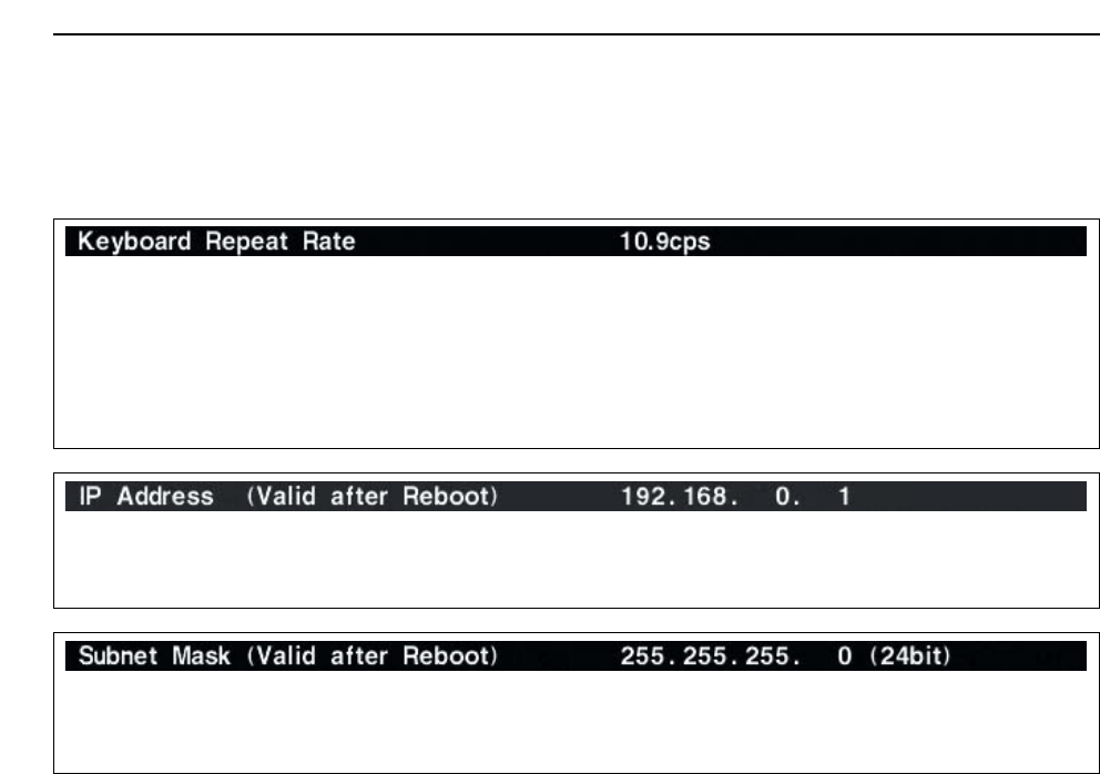
Sets subnet mask for the IC-7800.
Turn the transceiver power OFF then ON to effective
the setting.
Sets the repeating rate for the connected keyboard
within 2.0 to 30.0 cps in 0.1 cps steps.
(default: 10.9 cps) *cps=character per second
When a key of the connected keyboard is pressed
and held, the character is repeatedly input with the set
speed.
Sets IP address for the IC-7800.
Turn the transceiver power OFF then ON to effective
the setting.
12-21
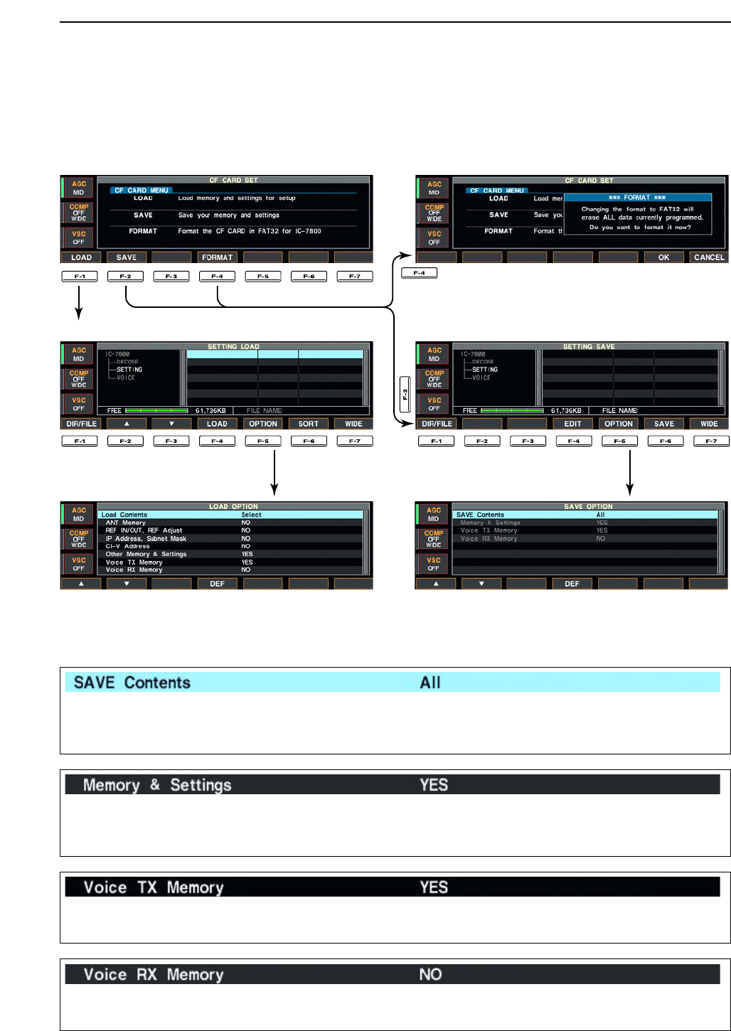
■CF card set menu
DCF card set screen arrangement
• CF card set menu
• Setting load screen (p. 12-24)
• Load option set mode (p. 12-22)
• Format menu (p. 12-26)
• Setting save screen (p. 12-23)
• Save option set mode (p. 12-21)
12
SET MODE
DSave option set mode
Selects file saving condition from All and Select.
(default: All)
• All : Saves the all following contents. The follow-
ing items cannot be selected.
• Select : Saves the selected contents only.
Selects memory channel contents and other settings
saving condition YES and NO. (default: YES).
• YES : Saves memory channel contents and set-
tings of miscellaneous (Other) set mode.
• NO : Not saves them.
Selects the voice TX memory saving condition YES
and NO. (default: YES).
• YES : Saves the voice TX memory.
• NO : Not saves.
Selects the voice RX memory saving condition YES
and NO. (default: NO).
• YES : Saves the voice RX memory.
• NO : Not saves.
12-22
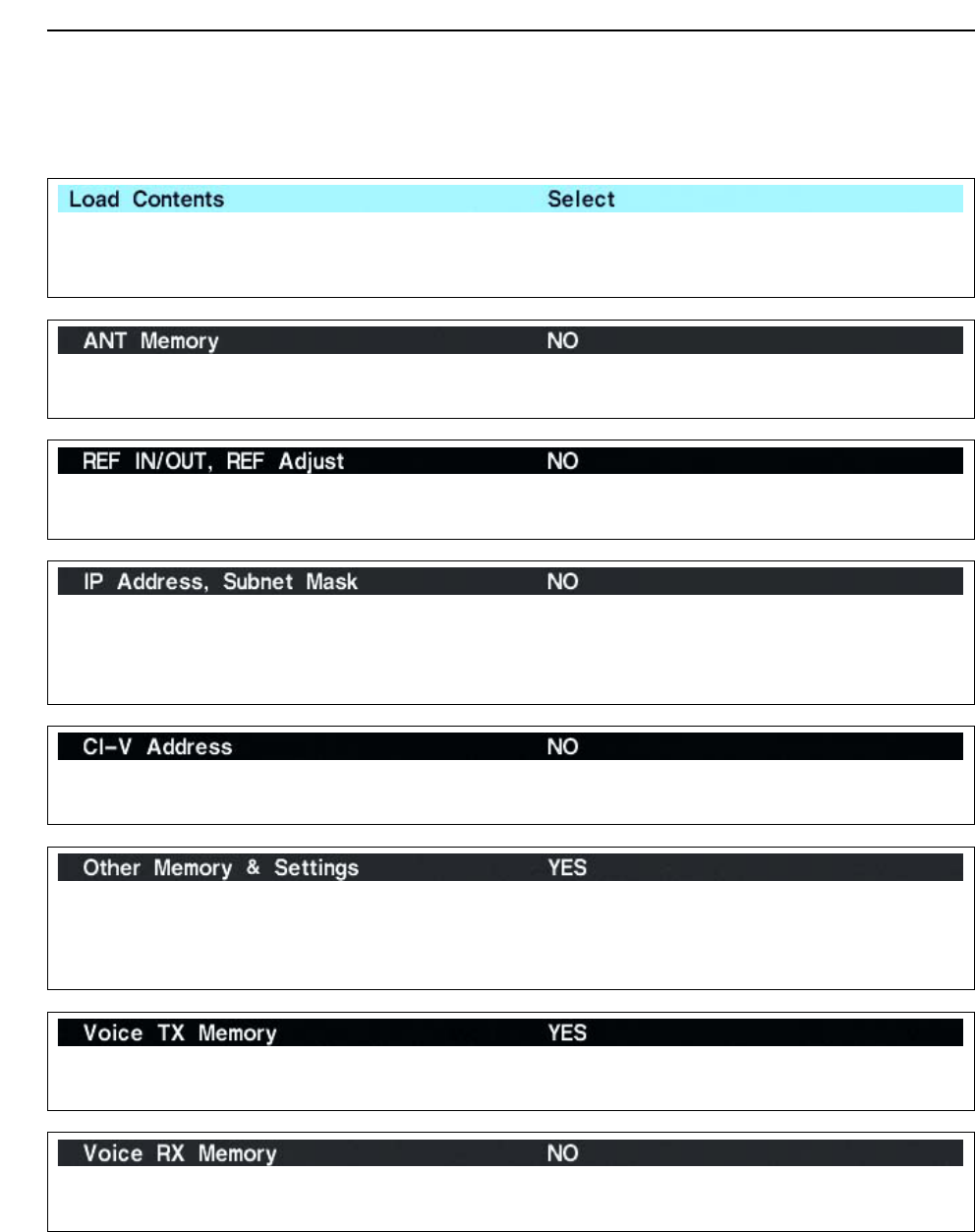
DLoad option set mode
12 SET MODE
Selects file loading condition from All and Select.
(default: Select)
• All : Loads and sets the all following contents.
The following items cannot be selected.
• Select : Loads and sets the selected contents only.
Selects the antenna memory setting loading condition
YES and NO. (default: NO).
• YES : Loads and sets the antenna memory.
• NO : Use the original antenna memory setting.
Selects the reference signal setting loading condition
YES and NO. (default: NO).
• YES : Loads and sets the reference signal setting.
• NO : Use the original reference signal setting.
Selects the IP address and subnet mask setting load-
ing condition YES and NO. (default: NO).
• YES : Loads and sets the IP address and subnet
mask setting.
• NO : Use the original IP address and subnet
mask setting.
Selects the CI-V address setting loading condition
YES and NO. (default: NO).
• YES : Loads and sets the CI-V address setting.
• NO : Use the original CI-V address setting.
Selects memory channel contents and other settings
loading condition YES and NO. (default: YES).
• YES : Loads and sets memory channel contents
and other settings.
• NO : Use the original memory channel contents
and other settings.
Selects the voice TX memory loading condition YES
and NO. (default: YES).
• YES : Loads and sets the voice TX memory.
• NO : Use the original the voice TX memory.
Selects the voice RX memory loading condition YES
and NO. (default: NO).
• YES : Loads and sets the voice RX memory.
• NO : Use the original the voice RX memory.
12-23
12
SET MODE
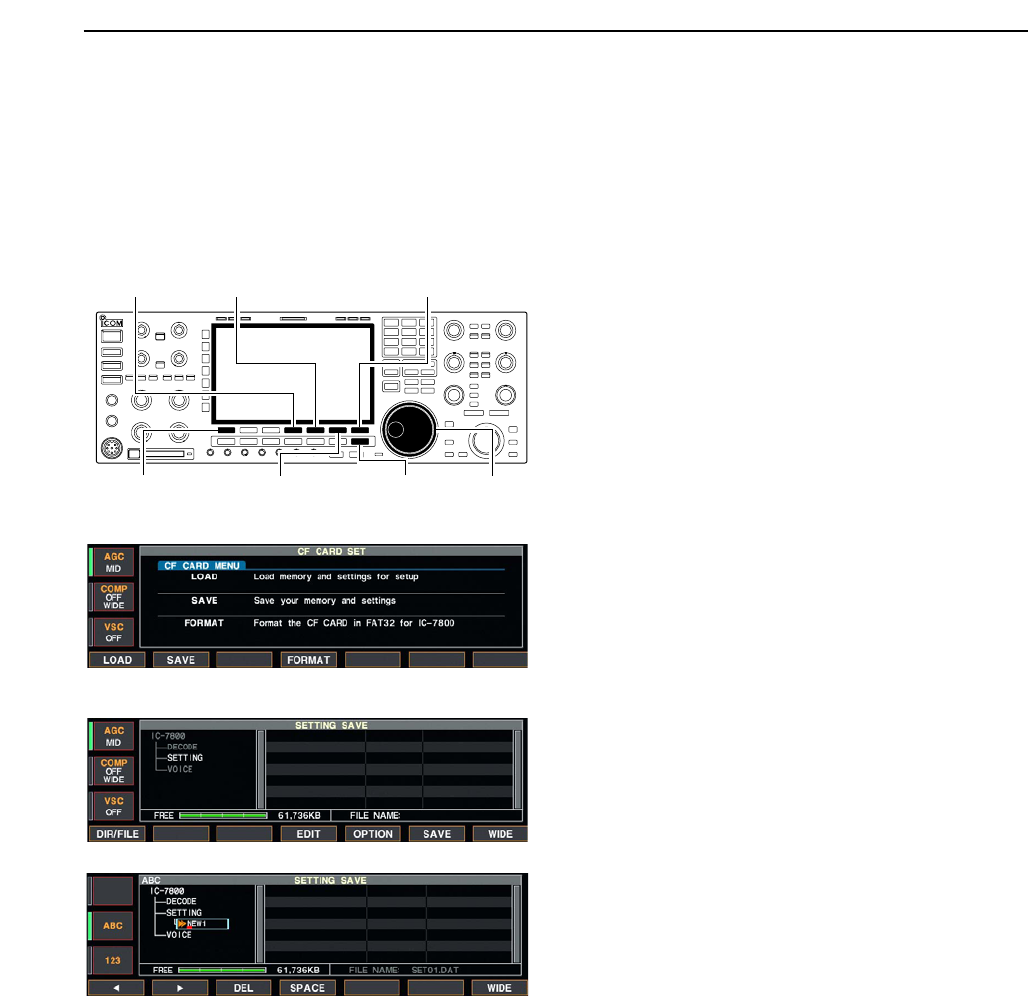
■File saving
Memory channel contents, set mode settings, etc. can
be saved into the CF (Compact Flash) memory card
for backup.
qDuring set mode menu screen indication, push
[F-7•CF CARD] to select CF card set menu screen.
wPush [F-2•SAVE] to select setting save screen.
eChange the following conditions if desired.
• File name:
zPush [F-4•EDIT] to select file name edit con-
dition.
• Push [F-1• DIR/FILE] several times to select the
file name, if necessary.
xPush [ABC], [123] or [Symbol] to select the
character group, then rotate the main dial to
select the character.
• [ABC] : A to Z (capital letters); [123]: 0 to 9 (nu-
merals); [Symbol]: ! # $ % & ‘ ` ^ + – = ( ) [ ] { } _ ~
@ can be selected.
• Push [F-1•Ω] to move the cursor left, push [F-2•≈]
to move the cursor right, push [F-3•DEL] to delete
a character and push [F-4•SPACE] to insert a
space.
cPush [EXIT/SET] to set the file name.
• Save option
zPush [F-5•OPTION] to enter save option set
mode.
xPush [F-1•Y] or [F-2•Z] to select the item,
then rotate the main dial to select the desired
setting. (see p. 12-21 for details)
• “Text” is the default setting.
• Push [F-4•DEF] for 1 sec. to select the default set-
ting.
cPush [EXIT/SET] to return to the previous in-
dication.
• Saving location
zPush [F-1•DIR/FILE] to select tree view
screen.
xSelect the desired directory or folder in the CF
memory card.
• Push [F-4•Ω≈] to select the upper directory.
• Push [F-2•Y] or [F-3•Z] to select folder in the
same directory.
• Push [F-4•Ω≈] for 1 sec. to select a folder in the
directory.
• Push [F-5•REN/DEL] to rename the folder.
• Push [F-5•REN/DEL] for 1 sec. to delete the
folder.
• Push [F-6•MAKE] for 1 sec. to making a new
folder. (Edit the name with the same manner as
the “• File name” above.)
cPush [F-1•DIR/FILE] twice to select the file
name.
rPush [F-6•SAVE].
• Confirmation screen appears.
tPush [F-6•OK] to save.
• After the saving is completed, return to CF card set
menu automatically.
[F-1•DIR/FILE]
[F-5•OPTION][F-4•EDIT]
[F-6•SAVE]/[F-6•OK]
[F-7•WIDE]/[F-7•CANCEL]
[EXIT/SET] Main dial
12-24
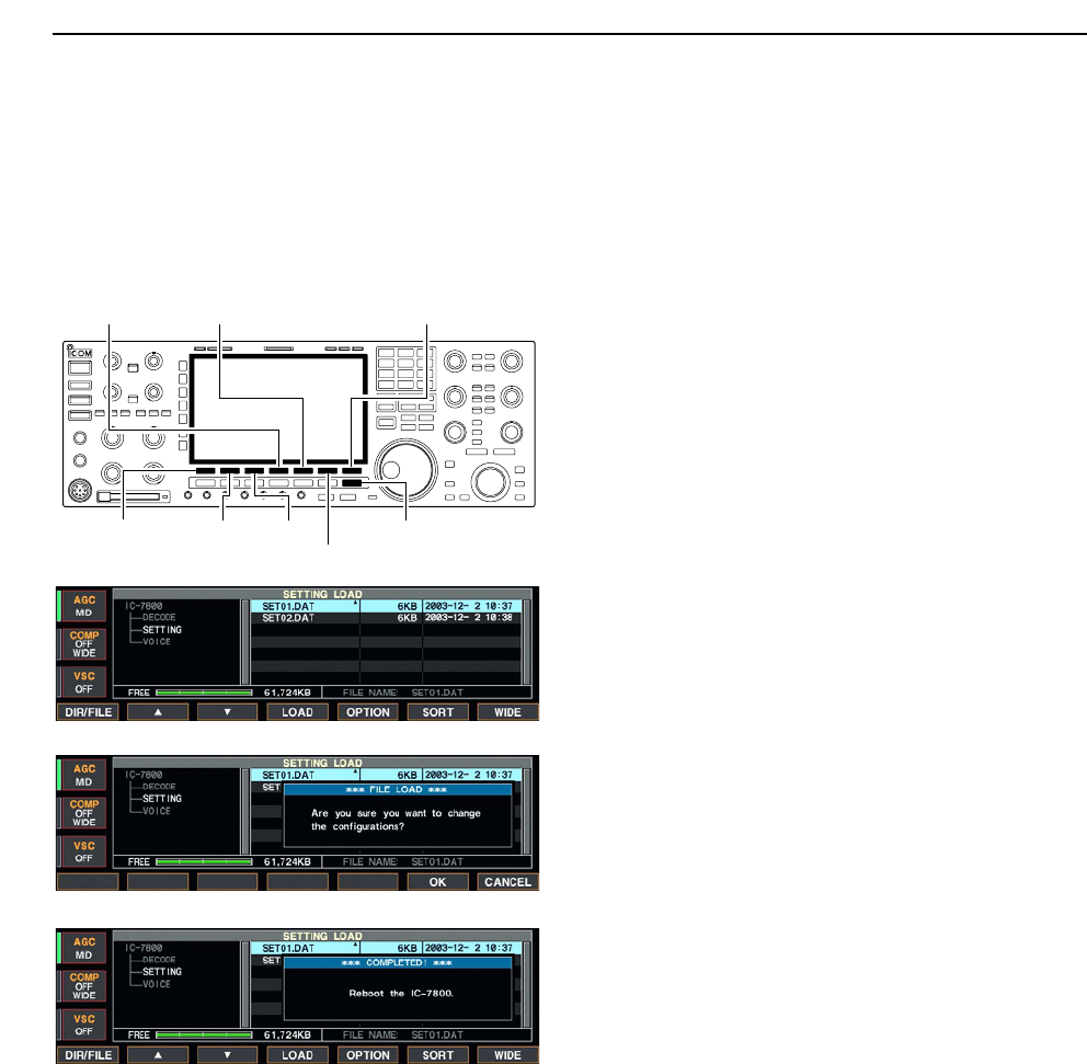
■File loading
By loading the saved setting file from the CF card, you
can easily set up another IC-7800— several operators
settings can easily be re-set to one IC-7800.
qDuring set mode menu screen indication, push
[F-7•CF CARD] to select CF card set menu screen.
wPush [F-1•LOAD] to select setting load screen.
• The indicator beside the CF card slot blinks.
• After the CF card contents are displayed, the indicator
goes off.
ePush [F-5•OPTION] to select load option set mode,
then set the desired loading conditions, if desired.
• See page 12-22 for details.
rPush [F-2•Y] or [F-3•Z] to select the desired set-
ting file.
tPush [F-4•LOAD].
• Confirmation screen appears.
yPush [F-6•OK] to starts loading.
• After the lading is completed, the message dialog, “Re-
boot the IC-7800,” appears.
uTurn the transceiver power OFF then ON to effec-
tive the setting.
[F-1•DIR/FILE]
[F-5•OPTION][F-4•LOAD]
[F-6•SORT]/[F-6•OK]
[F-7•WIDE]/[F-7•CANCEL]
[F-3•Z][F-2•Y][EXIT/SET]
12 SET MODE
12-25
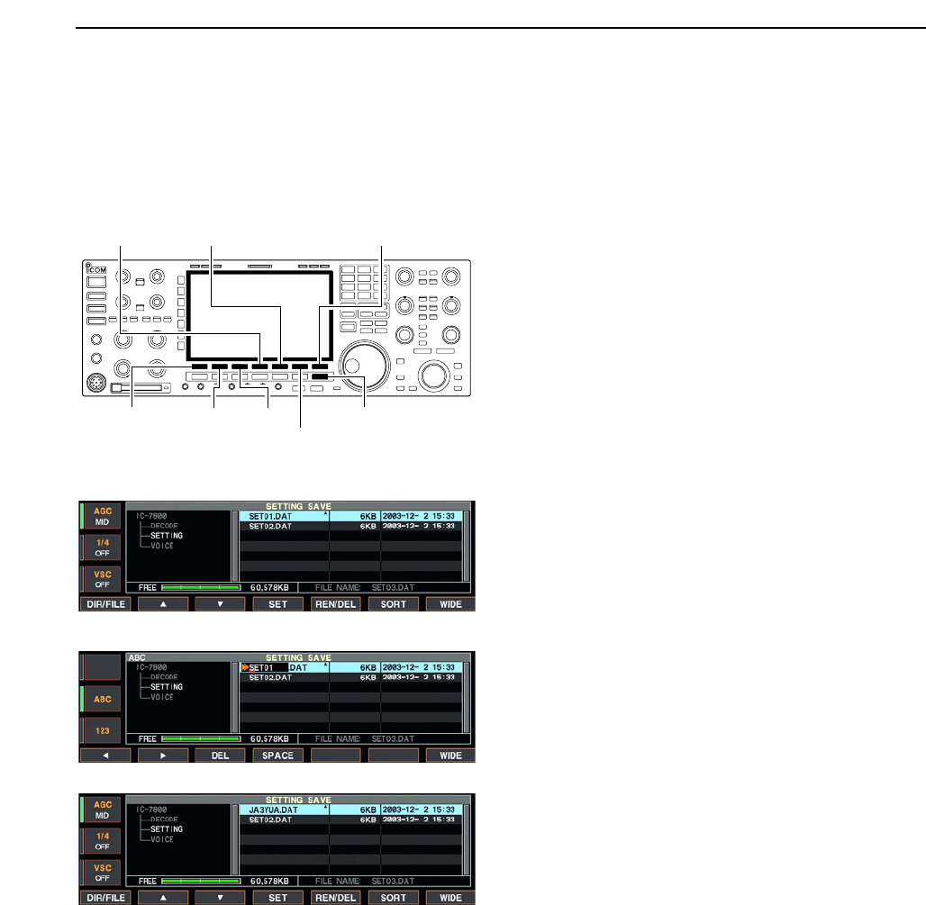
■Changing the file name
The file name, saved in the CF card, can be re-named
from the transceiver as desired.
qDuring setting save screen indication, push
[F-1•DIR/FILE] to selects tree view screen.
• Push [F-2•Y] or [F-3•Z] to select the desired folder.
• “DECODE,” “SETTING” and “VOICE” folders are avail-
able as the default.
• After the folder is selected, push [F-2•Ω≈] for 1 sec. to
display content folder(s), if available.
wPush [F-1•DIR/FILE] to select file list screen.
ePush [F-2•Y] or [F-3•Z] to select the desired file.
rPush [F-5•REN/DEL] momentarily to select the file
name edit condition.
tPush [ABC], [123] or [Symbol] to select the charac-
ter group, then rotate the main dial to select the
character.
• [ABC] : A to Z (capital letters); [123]: 0 to 9 (numerals);
[Symbol]: ! # $ % & ‘ ` ^ + – = ( ) [ ] { } _ ~ @ can be se-
lected.
• Push [F-1•Ω] to move the cursor left, push [F-2•≈] to
move the cursor right, push [F-3•DEL] to delete a char-
acter and push [F-4•SPACE] to insert a space.
• Pushing the transceiver’s keypad, [0]–[9], can also enter
numerals.
yPush [EXIT/SET] to set the file name.
[F-1•DIR/FILE]
[F-5•REN/DEL][F-4•Ω≈]
[F-6•MAKE]
[F-7•WIDE]/[F-7•CANCEL]
[F-3•Z][F-2•Y][EXIT/SET]
12
SET MODE
12-26
■Deleting a file
RECOMMENDATION! Deleted setting file never re-
storable. Confirm the contents before deleting a set-
ting file is recommended.
qDuring setting save screen indication, push [F-
1•DIR/FILE] to select tree view screen.
• Push [F-2•Y] or [F-3•Z] to select the desired folder.
• “DECODE,” “SETTING” and “VOICE” folders are avail-
able as the default.
• After the folder is selected, push [F-2•Ω≈] for 1 sec. to
display content folder(s), if available.
wPush [F-1•DIR/FILE] to select file list screen.
ePush [F-2•Y] or [F-3•Z] to select the desired file to
be deleted.
rPush [F-5•REN/DEL] for 1 sec.
• Confirmation screen appears.
tPush [F-6•OK] to delete.
• After the deleting, return to setting save screen auto-
matically.
■Formatting the CF card
The all saved data in the CF memory card can be
erased.
IMPORTANT! Formatting erases all saved data in
the CF memory card. Make a buckup file in your PC,
or any other things, is recommended.
qDuring CF card set menu indication, push
[F-4•FORMAT] for 1 sec.
• Confirmation screen appears.
wPush [F-6•OK] to format.
• Push [F-7•CANCEL] to cancel.
eReturns to CF card set menu indication automati-
cally.
12 SET MODE

13-1
MAINTENANCE Section 13
■Troubleshooting ……………………………………………………… 13-2
DTransceiver power ………………………………………………… 13-2
DTransmit and receive ……………………………………………… 13-2
DScanning …………………………………………………………… 13-3
DDisplay ……………………………………………………………… 13-3
■Main dial brake adjustment ………………………………………… 13-3
■Voice synthesizer operation ………………………………………… 13-3
■SWR reading …………………………………………………………… 13-4
■Screen type and font selections …………………………………… 13-4
■Frequency calibration (approximate) ……………………………… 13-5
■Opening the transceiver’s case ……………………………………… 13-6
■Clock backup battery replacement ………………………………… 13-6
■Fuse replacement …………………………………………………… 13-7
■Resetting the CPU …………………………………………………… 13-7
■About protection indications ………………………………………… 13-8

■Troubleshooting
The following chart is designed to help you correct
problems which are not equipment malfunctions.
If you are unable to locate the cause of a problem or
solve it through the use of this chart, contact you near-
est Icom Dealer or Service Center.
DTransceiver power
DTransmit and receive
PROBLEM POSSIBLE CAUSE SOLUTION REF.
No sounds come out from
the speaker.
Sensitivity is too low, and
only strong signals are
audible.
Received audio is unclear
or distorted.
The [ANT] switch does not
function
Transmitting is impossible.
Output power is too low.
No contact possible with
another station.
Transmit signal is unclear
or distorted.
Repeater cannot be
accessed.
• Volume level is too low.
• The squelch is closed.
• The transceiver is in transmitting condition.
• The antenna is not connected properly.
• The antenna for another band is selected.
• The antenna is not properly tuned.
• The attenuator is activated.
• Wrong operating mode is selected.
• PBT function is activated.
• Noise blanker is turned ON when receiving a
strong signal.
• Preamp is activated.
• The noise reduction is activated and the [NR]
control is too far clockwise.
• The antenna switch has not been activated.
• The operating frequency is not set to a ham
band.
• [RF PWR] is set too far counterclockwise
• [MIC] is set too far counterclockwise
• The antenna for another band is selected.
• The antenna is not properly tuned.
• RIT or ∂TX function is activated.
• Split frequency function and/or dualwatch are
activated.
• [MIC] is set too far clockwise
• Split frequency function is not activated.
• Programmed subaudible tone frequency is
wrong.
• Rotate [AF] clockwise to obtain a suitable lis-
tening level.
• Turn [SQL] to 10 o’clock position to open the
squelch.
• Push [TRANSMIT] to receive or check the
SEND line of an external unit, if connected.
• Re-connect to the antenna connector.
• Select an antenna suitable for the operating
frequency.
• Push [TUNER] for 1 sec. to manually tune the
antenna.
• Push [ATT] several times to select “ATT OFF.”
• Select a suitable operating mode.
• Push [PBT CLR] for 1 sec. to reset the function.
• Push [NB] to turn the noise blanker OFF.
• Push [P.AMP] once or twice to turn the function
OFF.
• Set the [NR] control for maximum readability.
• Set the antenna switch in set mode to “Auto” or
“Manual.”
• Set the frequency to a ham band.
• Rotate [RF PWR] clockwise.
• Set [MIC] to a suitable position.
• Select an antenna suitable for the operating
frequency.
• Push [TUNER] for 1 sec. to manually tune the
antenna.
• Push [RIT] or [∂TX] to turn the function OFF.
• Push [SPLIT] and/or [DUALWATCH] to turn the
function OFF.
• Set [MIC] to a suitable position.
• Push [SPLIT] to to turn the function ON
• Reset the frequency using set mode.
p. 3-9
p. 3-9
p. 3-12
—
p. 10-2
p. 10-5
p. 5-9
p. 3-8
p. 5-12
p. 5-17
p. 5-9
p. 5-18
p. 10-4
p. 3-5
p. 3-12
p. 3-12
p. 10-2
p. 10-5
pgs. 5-10,
6-4
pgs. 5-16,
6-4
p. 3-12
p. 6-6
p. 4-32
PROBLEM POSSIBLE CAUSE SOLUTION REF.
13-2
13 MAINTENANCE
Power does not come on
when the [POWER] switch
is pushed.
• Power cable is improperly connected.
• The internal power supply is turned OFF.
• Circuit breaker is activated.
• Re-connect the AC power cable correctly.
• Turn the internal power supply ON.
• Check for the cause, then re-set the circuit
breaker.
p. 2-4
p. 3-2
—
13-3
DScanning
DDisplay
■Main dial brake adjustment
The tension of the main dial may be adjusted to suit
you preference.
The brake adjustment is located on the bottom side of
the front panel. See the figure at left.
Slide the brake adjustment to comfortable tension level
while turing the dial continuously and evenly in one di-
rection.
■Voice synthesizer operation
The IC-7800 has built-in voice synthesizer to announce
the frequency, mode, etc. (S-meter level can also be
announced—p. 12-16) in clear, electronically-gener-
ated voice, in English (or Japanese).
➥Push [SPEECH] to announce the currently selected
frequency, etc.
• Push [SPEECH] for 1 sec. to additionally announce the
selected mode.
➥Pushing a mode switch also announces the appro-
priate mode. (p. 12-16)
The output level of the voice synthesizer can be ad-
justed in level set mode. (p. 12-5)
[SPEECH] for sub
[SPEECH] for main
Light
Heavy
13
MAINTENANCE
PROBLEM POSSIBLE CAUSE SOLUTION REF.
Programmed scan does
not stop.
Programmed scan does
not start.
Memory scan does not
start
Select memory scan does
not start
• Squelch is open.
•
The same frequencies have been programmed
in scan edge memory channels P1 and P2.
• 2 or more memory channels have not been
programmed.
• 2 or more memory channels have not been
designated as select channels.
• Set [SQL] to the threshold point.
• Program different frequencies in scan edge
memory channel P1 and P2.
• Program more than 2 memory channels.
• Designate more than 2 memory channels as
select channels for the scan.
p. 3-9
p. 8-4
p. 8-4
p. 9-7
PROBLEM POSSIBLE CAUSE SOLUTION REF.
The displayed frequency
does not change properly.
• The dial lock function is activated.
• A set mode screen is selected.
• The internal CPU has malfunctioned.
•
Push [LOCK] to turn the function OFF.
• Push [EXIT/SET] several times to exit the set
mode screen.
• Reset the CPU.
p. 5-18
p. 12-2
p. 13-7
13-4
■SWR reading
The SWR meter indicates the SWR over the transmis-
sion line in all modes.
qPush [TUNER] to turn the antenna tuner OFF.
wPush [METER] for 1 sec. to display multi-function
meter.
ePush [RTTY/PSK] once or twice to select RTTY
mode.
rPush [TRANSMIT].
tRotate [RF PWR] clockwise past the 12 o’clock po-
sition for more than 30 W output power.
yRead the SWR on the SWR meter gage.
uPush [EXIT/SET] to close multi-function meter.
The built-in antenna tuner matches the transmitter
to the antenna when the SWR is lower than 3 : 1.
■Screen type and font selections
3 types of screen images and 18 types of frequency
readout indication fonts are available in the IC-7800.
qPush [EXIT/SET] several times to close multi-func-
tion screen, if necessary.
wPush [F-7•SET] to select set mode menu screen.
ePush [F-3•DISP] to enter display set mode.
rPush [F-1•Y] or [F-2•Z] to select “Display Type”
item when selecting the screen image, select “Dis-
play Font” when selecting the frequency readout in-
dication font.
tRotate the main dial to select the desired screen
image or font.
• Screen image is selectable from A, B and C.
• Italic (1)/(2)/(3)/(4), Round (1)/(2)/(3), Shadow (1)/(2)/(3),
Qubic (1)/(2)/(3)/(4) and IC-780 (1)/(2)/(3)/(4) are avail-
able for the frequency readout font.
yPush [EXIT/SET] twice to exit from display set
mode.
S
ID
0
510
15
0
010
44
ALC 52V VD
20
dB
11.5 23∞
10 50 100 150 200 250
PO
SWR
COMP
A
W
1
59+20 +40 +60dB
Better than 1.5:1
[RF PWR]
[RTTY/PSK][EXIT/SET]
[METER][TRANSMIT]
[TUNER]
13 MAINTENANCE
• Screen image example— type C
13-5
■Frequency calibration (approximate)
A very accurate frequency counter is required to cali-
brate the frequency of the transceiver. However, a
rough check may be performed by receiving radio sta-
tion WWVH, or other standard frequency signals.
CAUTION: The IC-7800 has been thoroughly ad-
justed and checked at the factory before being
shipped. You should not calibrate frequencies, ex-
cept for special reasons.
qPush [SSB] to select USB mode.
wPush [PBT CLEAR] for 1 sec. to clear the PBT set-
ting and make sure that the RIT/∂TX function is not
activated.
eSet the frequency to the standard frequency station
minus 1 kHz.
• When receiving WWVH (15.00000 MHz) as a standard
frequency, set the operating frequency for
14.99900 MHz.
• Other standard frequency can also be used.
rPush [EXIT/SET] several times to close a multi-
function screen, if necessary.
• Calibration marker item tPush [F-7•SET] to select set mode menu screen.
yPush [F-5•OTHERS] to enter miscellaneous (oth-
ers) set mode.
uPush [F-1•Y] several times to select the “Calibra-
tion Marker” item.
iRotate the main dial clockwise to turn the calibra-
tion marker ON.
oPush [EXIT/SET] once to return to set mode menu
screen.
!0 Push [F-2•ACC] to enter accessory set mode.
!1 Push [F-2•Z] several times to select the “REF Ad-
just” item.
!2 Rotate the main dial to adjust for a zero beat with
the received standard signal as shown at left.
• REF Adjust item • Zero beat means that two signals are exactly the same
frequency, resulting in a single tone being emitted.
!3 Turn the calibration marker OFF in miscellaneous
(others) set mode.
!4 Push [EXIT/SET] twice to exit set mode.
[F-1•Y] [F-2•ACC]/[F-2•Z]
[F-5•OTHERS]
[EXIT/SET] Main dial
[F-7•SET]
13
MAINTENANCE
13-6
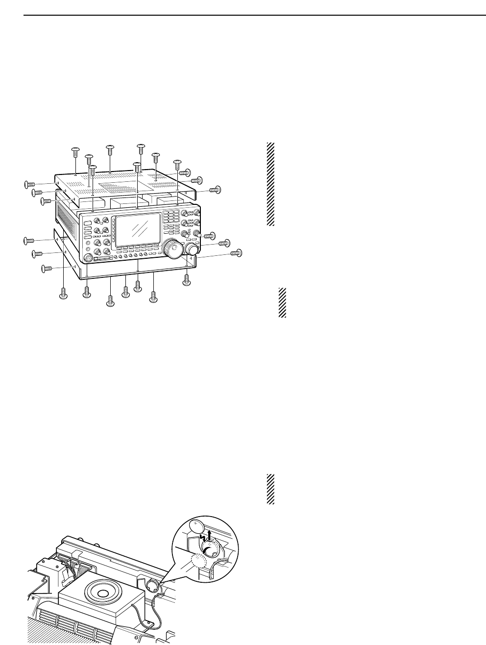
■Opening the transceiver’s case
Follow the case opening procedures shown here when
you want to replace the clock backup battery or cir-
cuitry fuse,
CAUTION!: DISCONNECT the AC power cable
from the transceiver before performing any work on
the transceiver. Otherwise, there is danger of elec-
tric shock and/or equipment damage.
CAUTION!: The transceiver weighs approx. 25 kg
(55 lb). 2 peoples should be present to lift up or turn
over the transceiver.
qRemove the 8 screws from the top of the trans-
ceiver and the 6 screws from the sides, then lift up
the top cover.
wTurn the transceiver upside down.
CAUTION: NEVER HOLD THE MAIN DIAL OR
ANY OTHER KNOBS when the transceiver is
upside down. This may damage the transceiver.
eRemove 7 screws from the bottom, and the 6
screws from the sides, then lift up the bottom cover.
■Clock backup battery replacement
The IC-7800 has a lithium backup battery (CR2032) in-
side for clock and timer functions. The usual life of the
backup battery is approximately 2 years.
When the backup battery exhausted, the transceiver
transmits and receives normally but cannot retain the
current time.
WARNING: DISCONNECT the AC power cable
from the AC outlet before removing the transceiver’s
cover.
qRemove the top cover as shown above.
wReplace the clock backup battery, located on the
front panel as illustrated at left.
• Make sure the battery polarity is correct.
eReturn the top cover to the original position.
rSet the date and time in time set mode. (p. 11-2)
13 MAINTENANCE
13-7
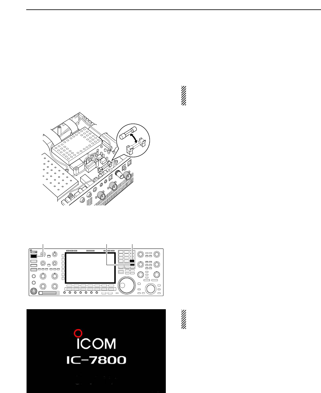
■Fuse replacement
When no external DC output is available from [EXT
DC] and ACC connectors, the internal fuse may be
damaged. Replace the fuse in this case.
WARNING: DISCONNECT the AC power cable
from the AC outlet before removing the transceiver’s
cover.
qRemove the bottom cover as shown left.
wReplace the damaged fuse with new, rated one
(FGB 2 A) as shown at left.
eReturn the bottom cover to the original position.
■Resetting the CPU
qTurn the main power switch on the rear panel ON.
• Make sure the transceiver power is still OFF.
wWhile pushing and holding [F-INP•ENT] and [MW],
push [POWER] to turn power ON.
• The internal CPU is reset.
• The CPU start up and it takes approx. 5 sec.
• The transceiver displays its initial VFO frequencies
when resetting is complete.
eCorrect the set mode settings after resetting, if de-
sired.
NOTE: Resetting CLEARS all programmed con-
tents in memory channels and returns programmed
values in set mode to default values.
[F-INP•ENT][MW][POWER]
13
MAINTENANCE
ALL CLEAR
13-8
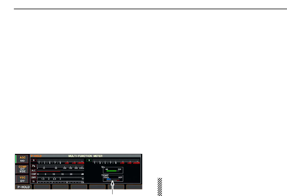
■About protection indications
The IC-7800 has a 2-step protection function to protect
the power amplifiers as follow.
The protector detects the power amplifier temperature
and activates when the temperature becomes ex-
tremely high.
• Power down transmission
Reduces the transmit output power to 100 W.
“LMT” appears beside the transmit indicator during
transmit.
• Transmission inhibit
Deactivate the transmitter.
The transmit indicator is displayed in gray during
transmit.
When the protector is activated, wait until the power
amplifier cools down using the transceiver stand-by
condition.
NOTE: DO NOT turn the transceiver power OFF.
The internal cooling fan does not function, so it will
take longer to cool down.
The power amplifier temperature can be confirmed in
multi-function meter, TEMP gauge.
Check the temperature
13 MAINTENANCE

14-1
CONTROL COMMAND Section 14
■Remote jack (CI-V) information ……………………………………… 14-2
DCI-V connection example ………………………………………… 14-2
DData format ………………………………………………………… 14-2
DCommand table …………………………………………………… 14-9
DTo send/read memory contents …………………………………… 14-9
DBand stacking register …………………………………………… 14-9
DCodes for memory keyer contents ……………………………… 14-9
DCodes for memory name, opening message
and clock 2 name contents ……………………………………… 14-9
DOffset frequency setting ………………………………………… 14-10
DRepeater tone/tone squelch frequency setting ………………… 14-10
DSSB transmission passband width setting …………………… 14-10
DColor setting ……………………………………………………… 14-10
DBandscope edge frequency setting …………………………… 14-10
DData mode with filter width setting ……………………………… 14-10
DAntenna memory setting ………………………………………… 14-10
14-2
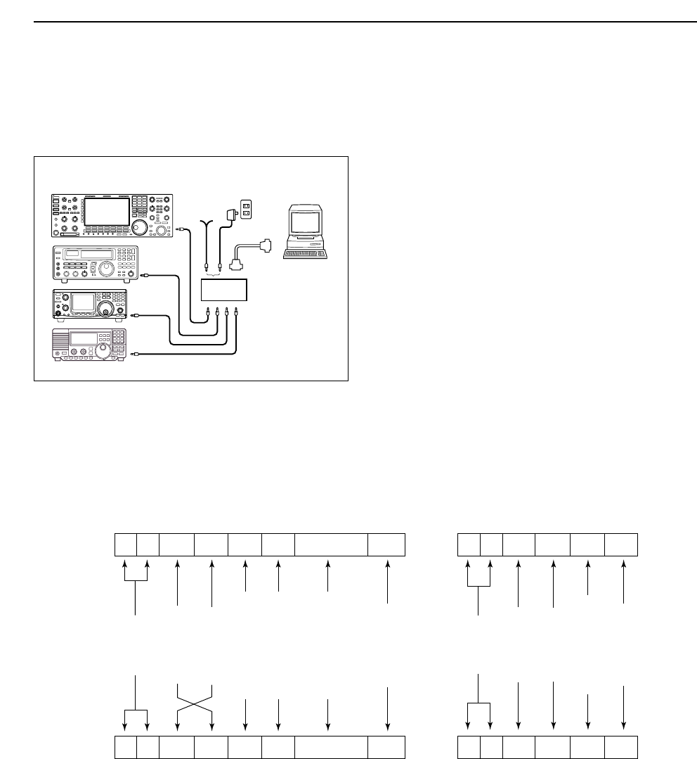
■Remote jack (CI-V) information
DCI-V connection example
The transceiver can be connected through an optional
CT-17 CI-V LEVEL CONVERTER to a PC equipped with an
RS-232C port. The Icom Communications Interface-V
(CI-V) controls the following functions of the trans-
ceiver.
Up to 4 Icom CI-V transceivers or transceivers can be
connected to a PC equipped with an RS-232C port.
See pgs. 12-18, 12-19 for setting the CI-V condition
using set mode.
DData format
The CI-V system can be operated using the following
data formats. Data formats differ according to com-
mand numbers. A data area or sub command is added
for some commands.
Controller to IC-7800
FE FE 6A E0 Cn Sc Data area FD
Preamble
code (fixed)
Transceiver’s
default address
Controller’s
default address
Command number
(see the command table)
Sub command number
(see command table)
BCD code data for
frequency or memory
number entry
End of message
code (fixed)
OK message to controller
FE FE E0 6A FB FD
FE FE E0 6A FA FD
Preamble
code (fixed)
Controller’s
default address
Transceiver’s
default address
OK code
(fixed)
End of message
code (fixed)
NG message to controller
NG code
(fixed)
IC-7800 to controller
qwert y u
FE FE E0 6A Cn Sc Data area FD
qwert y u
9–15 V
DC
personal
computer
ct- 17
BC-25
(optional)
IC-7800
mini-plug cable
14 CONTROL COMMAND

14-3
DCommand table
14
CONTROL COMMAND
Command Sub command Description
00 — Send frequency data
01 Same as Send mode data
command 06
02 — Read band edge frequencies
03 — Read operating frequency
04 — Read operating mode
05 — Set operating frequency
06 00 Select LSB
01 Select USB
02 Select AM
03 Select CW
04 Select RTTY
05 Select FM
07 Select CW-R
08 Select RTTY-R
12 Select PSK
13 Select PSK-R
07 — Select VFO mode
B0 Exchange main and sub bands
B1 Equalize main and sub bands
C0 Turn the dualwatch OFF
C1 Turn the dualwatch ON
D0 Select main band
D1 Select sub band
08 — Select memory mode
0001–0101* Select memory channel
*P1=0100, P2=0101
09 — Memory write
0A — Memory to VFO
0B — Memory clear
0E 00 Scan stop
01 Programmed/memory scan start
02 Programmed scan start
03 ∂F scan start
12 Fine programmed scan start
13 Fine ∂F scan start
22 Memory scan start
23 Select memory scan start
A1–A7 Set ∂F scan span (A1=±5 kHz;
A2=±10 kHz; A3=±20 kHz;
A4=±50 kHz; A5=±100 kHz;
A6=±500 kHz; A7=±1 MHz)
B0 Set as non-select channel
B1 Set as select channel (1=★1;
2=★2; 3=★3; when no data com-
mand is specified, the previously
set number or “★1” is selected)
B2 Set the number for select memory
scan (0=ALL; 1=★1; 2=★2; 3=★3)
D0 Set scan resume OFF
D3 Set scan resume ON
0F 00 Turn the split function OFF
01 Turn the split function ON
10 00 Select 10 Hz (1 Hz) tuning step
01 Select 100 Hz tuning step
02 Select 1 kHz tuning step
03 Select 5 kHz tuning step
04 Select 9 kHz tuning step
05 Select 10 kHz tuning step
06 Select 12.5 kHz tuning step
07 Select 20 kHz tuning step
08 Select 25 kHz tuning step
Command Sub command Description
11 — Select/read attenuator (0=OFF;
1=3 dB; 2=6 dB; 3=9 dB; 4=12 dB;
5=15 dB; 6=18 dB; 7=21 dB)
12 00 + RX ANT Select/read ANT1 selection
(00=RX ANT OFF; 01=RX ANT ON)
01 + RX ANT Select/read ANT2 selection
(00=RX ANT OFF; 01=RX ANT ON)
02 + RX ANT Select/read ANT3 selection
(00=RX ANT OFF; 01=RX ANT ON)
03 + RX ANT Select/read ANT4 selection
(00=RX ANT OFF; 01=RX ANT ON)
13 00 Announce with voice synthesizer
01 (00=all data; 01=frequency and
02 S-meter level; 02=receive mode)
14 01 + Level data [AF] level setting (0=max. CCW to
255=max. CW)
02 + Level data [RF] level setting (0=max. CCW to
255=11 o’clock)
03 + Level data [SQL] level setting (0=11 o’clock to
255=max. CW)
05 + Level data [APF] level setting
(0=Pitch–550 Hz, 128=Pitch,
255=Pitch+550 Hz)
06 + Level data [NR] level setting (0=min. to
255=max.)
07 + Level data Inside [TWIN PBT] setting or IF
shift setting (0=max. CCW,
128=center, 255=max. CW)
08 + Level data Outside [TWIN PBT] setting
(0=max. CCW, 128=center,
255=max. CW)
09 + Level data [CW PITCH] setting (0=300 Hz,
128=600 Hz, 255=900 Hz; 25 Hz
steps)
0A + Level data [RF POWER] setting (0=max.
CCW to 255=max. CW)
0B + Level data [MIC] setting (0=max. CCW to
255=max. CW)
0C + Level data [KEY SPEED] setting (0=max.
CCW to 255=max. CW)
0D + Level data [NOTCH] setting (0=low freq. to
255=high freq.)
0E + Level data [COMP] setting (0=max. CCW to
255=max. CW)
0F + Level data [DELAY] setting (0=max. CCW to
255=max. CW)
11 + Level data [AGC] control setting (0=max.
CCW to 255=max. CW)
12 + Level data [NB] control setting (0=max. CCW
to 255=max. CW)
13 + Level data [DIGI-SEL] setting (0=max. CCW
to 255=max. CW)
14 + Level data [DRIVE] setting (0=max. CCW to
255=max. CW)
15 + Level data [MONI GAIN] setting (0=max.
CCW to 255=max. CW)
16 + Level data [VOX GAIN] setting (0=max.
CCW to 255=max. CW)
17 + Level data [ANTI VOX] setting (0=max. CCW
to 255=max. CW)
18 + Level data [CONTRAST] setting (0=max.
CCW to 255=max. CW)
19 + Level data [BRIGHT] setting (0=max. CCW
to 255=max. CW)

14-4
DCommand table (continued)
14 CONTROL COMMAND
Command Sub command Description
15 01 Read squelch condition
02 Read S-meter level
11 Read RF power meter
12 Read SWR meter
13 Read ALC meter
14 Read COMP meter
15 Read VDmeter
16 Read IDmeter
16 02 Preamp (0=OFF; 1=preamp 1;
2=preamp 2)
12 AGC selection (0=OFF; 1=Slow;
2=Mid; 3=Fast)
22 Noise blanker (0=OFF; 1=ON)
32 Audio peak filter (0=OFF;
1=320 Hz; 2=160 Hz; 3=80 Hz)
40 Noise reduction (0=OFF; 1=ON)
41 Auto notch (0=OFF; 1=ON)
42 Repeater tone (0=OFF; 1=ON)
43 Tone squelch (0=OFF; 1=ON)
44 Speech compressor
(0=OFF; 1=ON)
45 Monitor (0=OFF; 1=ON)
46 VOX function (0=OFF; 1=ON)
47 Break-in (0=OFF; 1=semi break-
in; 2=full break-in)
48 Manual notch (0=OFF; 1=ON)
4C VSC (0=OFF; 1=ON)
4D Manual AGC (0=OFF; 1=ON)
4E DIGI-SEL (0=OFF; 1=ON)
4F Twin peak filter (0=OFF; 1=ON)
50 Dial lock (0=OFF; 1=ON)
19 00 Read the transceiver ID
1A 00 Send/read memory contents (see
p. 14-9 for details)
01 Send/read band stacking register
contents (see p. 14-9 for details)
02 Send/read memory keyer con-
tents (see p. 14-9 for details)
03 Send/read the selected filter width
(SSB, CW, PSK: 0=50 Hz to
40=3600 Hz; RTTY: 0=50 Hz to
31=2700 Hz; AM: 0=200 Hz to
49=10 kHz)
04 Send/read the selected AGC time
constant (0=OFF, 1=0.1/0.3 sec.
to 13=6.0/8.0 sec.)
050001 Send/read SSB TX Tone (Bass)
level (0 =–5 to 10=+5)
050002 Send/read SSB TX Tone (Treble)
level (0=–5 to 10=+5)
050003 Send/read SSB RX Tone (Bass)
level (0 =–5 to 10=+5)
050004 Send/read SSB RX Tone (Treble)
level (0=–5 to 10=+5)
050005 Send/read AM TX Tone (Bass)
level (0 =–5 to 10=+5)
050006 Send/read AM TX Tone (Treble)
level (0=–5 to 10=+5)
050007 Send/read AM RX Tone (Bass)
level (0 =–5 to 10=+5)
050008 Send/read AM RX Tone (Treble)
level (0=–5 to 10=+5)
050009 Send/read FM TX Tone (Bass)
level (0 =–5 to 10=+5)
050010 Send/read FM TX Tone (Treble)
level (0=–5 to 10=+5)
Command Sub command Description
1A 050011 Send/read FM RX Tone (Bass)
level (0 =–5 to 10=+5)
050012 Send/read FM RX Tone (Treble)
level (0=–5 to 10=+5)
050013 Send/read SSB TX bandwidth for
wide (see p. 14-10 for details)
050014 Send/read SSB TX bandwidth for
mid. (see p. 14-10 for details)
050015 Send/read SSB TX bandwidth for
narrow (see p. 14-10 for details)
050016 Send/read speech level (0=0% to
255=100%)
050017 Send/read CW side tone gain
(0=min. to 255=max.)
050018 Send/read CW side tone gain limit
(0=OFF, 1=ON)
050019 Send/read beep gain (0=min. to
255=max.)
050020 Send/read beep gain limit (0=OFF,
1=ON)
050021 Send/read headphones output
ratio (0=0.60 to 255=1.40)
050022 Send/read headphone output
selection (0=separated, 1=mixed)
050023 Send/read AF/SQL signal output
to ACC-A (0=Main; 1=Sub)
050024 Send/read AF/SQL signal output
to ACC-B (0=Main; 1=Sub)
050025 Send/read AF output level to
ACC-A (0=0% to 255=100%)
050026 Send/read AF output level to
ACC-B (0=0% to 255=100%)
050027 Send/read S/P DIF output level
(0=0% to 255=100%)
050028 Send/read MOD output level to
ACC-A (0=0% to 255=100%)
050029 Send/read MOD output level to
ACC-B (0=0% to 255=100%)
050030 Send/read S/P DIF MOD output
level (0=0% to 255=100%)
050031 Send/read MOD input connector
during DATA OFF
(0=MIC; 1=ACC-A; 2=ACC-B;
3=MIC/ACC-A; 4=MIC/ACC-B;
5=ACC-A/ACC-B; 6=MIC/ACC-
A/ACC-B; 7=S/P DIF)
050032 Send/read MOD input connector
during DATA1
(0=MIC; 1=ACC-A; 2=ACC-B;
3=MIC/ACC-A; 4=MIC/ACC-B;
5=ACC-A/ACC-B; 6=MIC/ACC-
A/ACC-B; 7=S/P DIF)
050033 Send/read MOD input connector
during DATA2
(0=MIC; 1=ACC-A; 2=ACC-B;
3=MIC/ACC-A; 4=MIC/ACC-B;
5=ACC-A/ACC-B; 6=MIC/ACC-
A/ACC-B; 7=S/P DIF)
050034 Send/read MOD input connector
during DATA3
(0=MIC; 1=ACC-A; 2=ACC-B;
3=MIC/ACC-A; 4=MIC/ACC-B;
5=ACC-A/ACC-B; 6=MIC/ACC-
A/ACC-B; 7=S/P DIF)

14-5
DCommand table (continued)
14
CONTROL COMMAND
Command Sub command Description
1A 050035 Send/read the band selection for
operating frequency band signal
output to ACC-A. (0=MAIN,
1=SUB, 2=TX)
050036 Send/read the band selection for
operating frequency band signal
output to ACC-A. (0=MAIN,
1=SUB, 2=TX)
050037 Send/read relay type selection
(0=Lead, 1=MOS-FET)
050038 Send/read main band’s external
meter output selection (0=Auto,
1=S (main), 2=Po, 3=SWR,
4=ALC, 5=COMP, 6=VD, 7=ID)
050039 Send/read sub band’s external
meter output selection (0=Auto,
1=S (sub), 2=Po, 3=SWR,
4=ALC, 5=COMP, 6=VD, 7=ID)
050040 Send/read main band’s external
meter output level
(0=0% to 255=100%)
050041 Send/read sub band’s external
meter output level
(0=0% to 255=100%)
050042 Send/read reference signal in/out
setting (0=OFF, 1=IN, 2=OUT)
050043 Send/read reference signal fre-
quency setting
(0=0% to 255=100%)
050044 Send/read LCD unit backlight
brightness (0=0% to 255=100%)
050045 Send/read switch indicator bright-
ness (0=0% to 255=100%)
050046 Send/read screen image type
(0=A, 1=B, 2=C)
050047 Send/read frequency readout font
(
0=Italic (1), 1=Italic (2), 2=Italic (3),
3=Italic (4), 4=Round (1),
5=Round (2), 6=Round (3),
7=Shadow (1), 8=Shadow (2),
9=Shadow (3), 10=Qubic (1),
11=Qubic (2), 12=Qubic (3),
13=Qubic (4), 14=IC-780 (1),
15=IC-780 (2), 16=IC-780 (3),
17=IC-780 (4))
050048 Send/read font for other than fre-
quency readout
(0=Normal, 1=Slim)
050049 Send/read meter type
(0=Standard, 1=Edgewise, 2=Bar)
050050 Send/read meter type during wide
screen or mini scope indication
(0=Edgewise, 1=Bar)
050051 Send/read peak hold set
(0=OFF, 1=ON)
050052 Send/read memory name indica-
tion setting (0=OFF, 1=ON)
050053 Send/read audio peak filter width
pop-up indication setting
(0=OFF, 1=ON)
050054 Send/read manual notch width
pop-up indication setting
(0=OFF, 1=ON)
050055 Send/read output signal setting for
external display (0=OFF, 1=ON)
050056 Send/read synchronous pulse
level setting (0=L, 1=H)
Command Sub command Description
1A 050057 Send/read opening message indi-
cation (0=OFF, 1=ON)
050058 Send/read opening message con-
tents (see p. 14-9 for details)
050059 Send/read date (20000101=1st
Jan. 2001 to 20991231=31st Dec.
2099)
050060 Send/read time (0000=00:00 to
2359=23:59)
050061 Send/read clock 2 function
(0=OFF, 1=ON)
050062 Send/read offset time for clock 2
(240001=–24:00 to 240000=+24:00)
050063 Send/read clock 2 name (up to 3-
character; see p. 14-9)
050064 Send/read calibration marker
(0=OFF, 1=ON)
050065 Send/read confirmation beep
(0=OFF, 1=ON)
050066 Send/read band edge beep
(0=OFF, 1=ON)
050067 Send/read main band’s beep
audio frequency
(50=500 Hz to 200=2000 Hz)
050068 Send/read sub band’s beep audio
frequency
(50=500 Hz to 200=2000 Hz)
050069 Send/read quick dualwatch func-
tion (0=OFF, 1=ON)
050070 Send/read quick split set (0=OFF,
1=ON)
050071 Send/read FM split offset –9.999
to +9.999 MHz for HF
(see p. 14-10 for details)
050072 Send/read FM split offset –9.999
to +9.999 MHz for 50 MHz
(see p. 14-10 for details)
050073 Send/read split lock set (0=OFF,
1=ON)
050074 Send/read tuner auto start set
(0=OFF, 1=ON)
050075 Send/read PTT tune set (0=OFF,
1=ON)
050076 Send/read transverter set
(0=OFF, 1=ON)
050077 Send/read transverter offset (see
p. 14-10 for details)
050078 Send/read RTTY mark frequency
(0=1275 Hz, 1=1615 Hz,
2=2125 Hz)
050079 Send/read RTTY shift width
(0=170 Hz, 1=200 Hz, 2=425 Hz)
050080 Send/read RTTY keying polarity
(0=Normal, 1=Reverse)
050081 Send/read PSK tone frequency
(0=1000 Hz, 1=1500 Hz,
2=2000 Hz)
050082 Send/read speech language
(0=English, 1=Japanese)
050083 Send/read speech speed (0=Slow,
1=Fast)
050084 Send/read S-level speech
(0=OFF, 1=ON)
050085 Send/read speech with a mode
switch operation (0=OFF, 1=ON)
050086 Send/read memo pad numbers
(0=5 ch, 1=10 ch)

14-6
DCommand table (continued)
14 CONTROL COMMAND
Command Sub command Description
1A 050087 Send/read main dial function
(0=MAIN, 1=MAIN+SUB)
050088 Send/read main dial auto TS
(0=OFF, 1=Low, 2=High)
050089 Send/read sub dial auto TS
(0=OFF, 1=Low, 2=High)
050090 Send/read mic. up/down speed
(0=Low, 1=High)
050091 Send/read quick RIT/∂TX clear
function (0=OFF, 1=ON)
050092 Send/read SSB notch operation
(0=Auto, 1=Manual,
2=Auto/Manual)
050093 Send/read AM notch operation
(0=Auto, 1=Manual,
2=Auto/Manual)
050094 Send/read DIGI-SEL control func-
tion (0=DIGI-SEL, 1=APF)
050095 Send/read band indication for fil-
ter set screen (0=Fix, 1=Auto)
050096 Send/read SSB/CW synchronous
tuning function (0=OFF, 1=ON)
050097 Send/read CW normal side set
(0=LSB, 1=USB)
050098 Send/read PSK normal side set
(0=LSB, 1=USB)
050099 Send/read band setting for audio
output from mic. connector
(0=MAIN+SUB, 1=SUB)
050100 Send/read external keypad set
for voice memory (0=OFF, 1=ON)
050101 Send/read external keypad set
for keyer memory (0=OFF, 1=ON)
050102 Send/read CI-V transceive set
(0=OFF, 1=ON)
050103 Send/read RS-232C function
(0=CI-V, 1=Decode)
050104 Send/read RS-232C decode
speed (0=300, 1=1200, 2=4800,
3=9600, 4=19200)
050105 Send/read keyboard type
(0=English, 1=Japanese)
050106 Send/read keyboard repeat delay
(10=100 msec. to 100=1000 msec.)
050107 Send/read keyboard repeat speed
(0=2.0 cps to 31=30.0 cps)
050108 Send/read IP address set
(0000000000000000=0.0.0.0 to
0255025502550255=255.255.25
5.255)
050109 Send/read subnet mask
(0=0.0.0.0 to 30=255.255.255.252)
050110 Send/read scope indication during
TX (0=OFF, 1=ON)
050111 Send/read scope max. hold
(0=OFF, 1=ON)
050112 Send/read scope center frequen-
cy set (0=Filter center, 1=Carrier
point center, 2=Carrier point cen-
ter (Abs. Freq.))
050113 Send/read waveform color for
receiving signal
(see p. 14-10 for details)
050114 Send/read waveform color for
max. hold
(see p. 14-10 for details)
Command Sub command Description
1A 050115 Send/read scope sweep speed
for ±2.5 kHz span
(0=Slow, 1=Mid., 2=Fast)
050116 Send/read scope sweep speed
for ±5 kHz span
(0=Slow, 1=Mid., 2=Fast)
050117 Send/read scope sweep speed
for ±10 kHz span
(0=Slow, 1=Mid., 2=Fast)
050118 Send/read scope sweep speed
for ±25 kHz span
(0=Slow, 1=Mid., 2=Fast)
050119 Send/read scope sweep speed
for ±50 kHz span
(0=Slow, 1=Mid., 2=Fast)
050120 Send/read scope sweep speed
for ±100 kHz span
(0=Slow, 1=Mid., 2=Fast)
050121 Send/read scope sweep speed
for ±250 kHz span
(0=Slow, 1=Mid., 2=Fast)
050122 Send/read scope edge frequen-
cies for 0.03 to 1.60 MHz band
(see p. 14-10 for details)
050123 Send/read scope edge frequen-
cies for 1.60 to 2.00 MHz band
(see p. 14-10 for details)
050124 Send/read scope edge frequen-
cies for 2.00 to 6.00 MHz band
(see p. 14-10 for details)
050125 Send/read scope edge frequen-
cies for 6.00 to 8.00 MHz band
(see p. 14-10 for details)
050126 Send/read scope edge frequen-
cies for 8.00 to 11.00 MHz band
(see p. 14-10 for details)
050127 Send/read scope edge frequen-
cies for 11.00 to 15.00 MHz band
(see p. 14-10 for details)
050128 Send/read scope edge frequen-
cies for 15.00 to 20.00 MHz band
(see p. 14-10 for details)
050129 Send/read scope edge frequen-
cies for 20.00 to 22.00 MHz band
(see p. 14-10 for details)
050130 Send/read scope edge frequen-
cies for 22.00 to 26.00 MHz band
(see p. 14-10 for details)
050131 Send/read scope edge frequen-
cies for 26.00 to 30.00 MHz band
(see p. 14-10 for details)
050132 Send/read scope edge frequen-
cies for 30.00 to 45.00 MHz band
(see p. 14-10 for details)
050133 Send/read scope edge frequen-
cies for 45.00 to 60.00 MHz band
(see p. 14-10 for details)
050134 Send/read auto voice monitor set
(0=OFF, 1=ON)
050135 Send/read voice memory short
play time (3=3 sec. to 10=10 sec.)
050136 Send/read voice memory normal
record time
(5= 5 sec. to 15=15 sec.)

14-7
DCommand table (continued)
14
CONTROL COMMAND
Command Sub command Description
1A 050137 Send/read contest number style
(0=Normal, 1=190→ANO,
2=190→ANT, 3=90→NO,
4=90→NT)
050138 Send/read count up trigger chan-
nel (1=M1, 2=M2, 3=M3, 4=M4)
050139 Send/read present number
(1–9999)
050140 Send/read CW keyer repeat time
(1=1 sec. to 60=60 sec.)
050141 Send/read CW keyer dot/dash
ratio (28=1:1:2.8 to 45=1:1:4.5)
050142 Send/read rise time (0=2 msec.,
1=4 msec., 2=6 msec.,
3=8 msec.)
050143 Send/read paddle polarity
(0=Normal, 1=Reverse)
050144 Send/read keyer type (0=Straight,
1=Bug-key, 2=ELEC-Key)
050145 Send/read mic. up/down keyer
set (0=OFF, 1=ON)
050146 Send/read RTTY decode USOS
(0=OFF, 1=ON)
050147 Send/read RTTY decode new line
code (0=CR,LF,CR+LF, 1=CR+LF)
050148 Send/read RTTY diddle (0=OFF,
1=Blank, 2=Letter)
050149 Send/read RTTY TX USOS
(0=OFF, 1=ON)
050150 Send/read RTTY auto CR+LF by
TX (0=OFF, 1=ON)
050151 Send/read RTTY time stamp set
(0=OFF, 1=ON)
050152 Send/read clock selection for time
stamp (0=Local time, 1=Clock 2)
050153 Send/read frequency stamp
(0=OFF, 1=ON)
050154 Send/read received text font color
(see p. 14-10 for details)
050155 Send/read transmitted text font
color (see p. 14-10 for details)
050156 Send/read time stamp text font
color (see p. 14-10 for details)
050157 Send/read text font color in TX
buffer (see p. 14-10 for details)
050158 Send/read PSK time stamp set
(0=OFF, 1=ON)
050159 Send/read clock selection for time
stamp (0=Local time, 1=Clock 2)
050160 Send/read frequency stamp
(0=OFF, 1=ON)
050161 Send/read received text font color
(see p. 14-10 for details)
050162 Send/read transmitted text font
color (see p. 14-10 for details)
050163 Send/read time stamp text font
color (see p. 14-10 for details)
050164 Send/read text font color in TX
buffer (see p. 14-10 for details)
050165 Send/read scan speed
(0=Low, 1=High)
050166 Send/read scan resume
(0=OFF, 1=ON)
050167 Send/read antenna selection for
0.03 to 1.60 MHz band
(see p. 14-10 for details)
Command Sub command Description
1A 050168 Send/read antenna selection for
1.60 to 2.00 MHz band
(see p. 14-10 for details)
050169 Send/read antenna selection for
2.00 to 6.00 MHz band
(see p. 14-10 for details)
050170 Send/read antenna selection for
6.00 to 8.00 MHz band
(see p. 14-10 for details)
050171 Send/read antenna selection for
8.00 to 11.00 MHz band
(see p. 14-10 for details)
050172 Send/read antenna selection for
11.00 to 15.00 MHz band
(see p. 14-10 for details)
050173 Send/read antenna selection for
15.00 to 20.00 MHz band
(see p. 14-10 for details)
050174 Send/read antenna selection for
20.00 to 22.00 MHz band
(see p. 14-10 for details)
050175 Send/read antenna selection for
22.00 to 26.00 MHz band
(see p. 14-10 for details)
050176 Send/read antenna selection for
26.00 to 30.00 MHz band
(see p. 14-10 for details)
050177 Send/read antenna selection for
30.00 to 45.00 MHz band
(see p. 14-10 for details)
050178 Send/read antenna selection for
45.00 to 60.00 MHz band
(see p. 14-10 for details)
050179 Send/read antenna temporary
memory set (0=OFF, 1=ON)
050180 Send/read antenna selection
(0=OFF, 1=Manual, 2=Auto)
050181 Send/read usage for ANT2
(0=OFF, 1=TX/RX)
050182 Send/read usage for ANT3
(0=OFF, 1=TX/RX)
050183 Send/read usage for ANT4
(0=OFF, 1=TX/RX, 2= RX)
050184 Send/read VOX delay (0=0.0 sec.
to 20=2.0 sec.)
050185 Send/read VOX voice delay
(0=OFF, 1=Short, 2=Long)
050186 Send/read NB depth (0=1 to 9=10)
050187 Send/read NB width
(0=0 to 255=255)
06 Send/read DATA mode with filter
set (see p. 14-10 for detail)
07 Send/read SSB transmit band-
width (0=WIDE, 1=MID, 2=NAR)
08 Send/read DSP filter shape
(0= sharp, 1= soft)
09 Send/read roofing filter set
(0=6 kHz, 1=15 kHz)
0A Send/read manual notch width
(0=Wide, 1=Mid., 2=Nar.)
10 Send/read lock function set
(0=OFF, 1=ON)

DCommand table (continued)
14-8
14 CONTROL COMMAND
Command Sub command Description
1B 00 Set/read repeater tone frequency
(see p. 14-10 for details)
01 Set/read TSQL tone frequency
(see p. 14-10 for details)
1C 00 Set/read the transceiver’s condi-
tion (0=Rx; 1=Tx)
01 Set/read antenna tuner condition
(0=OFF, 1=ON, 2=Start tuning or
while tuning)
14-9
14
CONTROL COMMAND
DTo send/read memory contents
When sending or reading memory contents, additional
code as follows must be added to appoint the memory
channel.
➥Additional code: 0000–0101 (0100=P1, 0101=P2)
DBand stacking register
To send or read the desired band stacking register’s
contents, combined code of the frequency band and
register codes as follows are used.
For example, when sending/reading the oldest con-
tents in the 21 MHz band, the code “0703” is used.
• Frequency band code
• Register code
DCodes for memory keyer contents
To send or read the desired memory keyer contents,
the channel and character codes as follows are used.
• Channel code
• Character’s code
DCodes for memory name, opening
message and clock 2 name contents
To send or read the desired memory name settings,
the character codes, instructed codes for memory
keyer contents as above, and follows are additionally
used.
•Character’s code— Alphabetical characters
•Character’s code— Symbols
Character ASCII code Character ASCII code
a–z 61–7A — —
Code Frequency band Frequency range (unit: MHz)
01 1.8 1.800000– 1.999999
02 3.5 3.400000– 4.099999
03 7 6.900000– 7.499999
04 10 9.900000–10.499999
05 14 13.900000–14.499999
06 18 17.900000–18.499999
07 21 20.900000–21.499999
08 24 24.400000–25.099999
09 28 28.000000–29.999999
10 50 50.000000–54.000000
12 GENE Other than above
Code Registered number
01 1 (latest)
02 2
03 3 (oldest)
Character ASCII code Description
0–9 30–39 Numerals
A–Z 41–5A Alphabetical characters
space 20 Word space
/ 2F Symbol
? 3F Symbol
, 2C Symbol
. 2E Symbol
^ 5E e.g., to send BT, enter ^4254
✱2A Inserts contest number (can be
used for 1 channel only)
Code Channel number
01 M1
02 M2
03 M3
04 M4
Character ASCII code Character ASCII code
!21#23
$24%25
&26¥5C
?3F ” 22
’27`60
+2B–2D
:3A;3B
=3D<3C
>3E ( 28
)29[5B
]5D{7B
}7D|7C
_5F–7E
@
14-10
14 CONTROL COMMAND
DOffset frequency setting
The following data sequence is used when sending or
reading the offset frequency setting.
DRepeater tone/tone squelch frequency
setting
The following data sequence is used when sending or
reading the tone frequency setting.
DSSB transmission passband width
setting
The following data sequence is used when sending or
reading the SSB transmission passband width setting.
DColor setting
The following data sequence is used when sending or
reading the color setting.
DBandscope edge frequency setting
The following data sequence is used when sending or
reading the bandscope edge frequency setting.
DData mode with filter width setting
The following data sequence is used when sending or
reading the data mode with filter width setting.
DAntenna memory setting
The following codes are used when sending or read-
ing the antenna memory setting.
0=ANT1, 1=ANT2, 2=ANT3, 3=ANT4,
4*=TX: ANT1, RX: ANT4, 5*=TX: ANT2, RX: ANT4,
6*=TX: ANT3, RX: ANT4
*RX should be selected for ANT4
q
XXXX
w
00=Data mode OFF
01=FIL1
02=FIL2
03=FIL3
00=Data mode OFF
01=Data mode 1 (D1)
02=Data mode 2 (D2)
03=Data mode 3 (D3)
1 kHz: 0–9
100 Hz: 0 (fixed)
100 kHz: 0–9
10 kHz: 0–9
10 MHz: 0–6
1 MHz: 0–9
1 MHz: 0–9
10 MHz: 0–6
10 kHz: 0–9
100 kHz: 0–9
100 Hz: 0 (fixed)
1 kHz: 0–9
q
XXXXXXXXXXXX
werty
Lower edge Higher edge
1000
100
10
1
q
0XXX0XXX0XXX
werty
1000
100
10
1
1000
100
10
1
R (Red) G (Green) B (Blue)
Using 0000–0255 for each color element.
XX
Higher edge: 0=2500 Hz
1=2700 Hz
3=2900 Hz
Lower edge: 0=100 Hz
1=300 Hz
3=500 Hz
100Hz digit: 0–2
10 Hz digit: 0–9
1 Hz digit: 0–9
0.1 Hz digit: 0–9
Fixed digit: 0*
Fixed digit: 0*
q*
00XXX
we
X
*Not necessary when setting a frequency.
1 kHz digit: 0–9
100 Hz digit: 0 (fixed)
100 kHz digit: 0–9
10 kHz digit: 0–9
10 MHz digit: 0–9†
1 MHz digit: 0–4
Direction:
00=+ direction
01=– direction
q
0XXXXXX
we
0
r*
*No need to enter for transverter offset frequency setting.
†Transverter offset only; Fix to ‘0’ for split offset setting.

15-1
SPECIFICATIONS AND OPTIONS Section 15
■Specifications ………………………………………………………… 15-2
DGeneral ……………………………………………………………… 15-2
DTransmitter ………………………………………………………… 15-2
DReceiver …………………………………………………………… 15-3
DAntenna tuner ……………………………………………………… 15-3
■Options ………………………………………………………………… 15-4

15-2
■Specifications
DGeneral
• Frequency coverage (unit: MHz) :
Receiver 0.030000–60.000000*1
Transmitter 1.800000–1.999999*2, 3.500000–3.999999*2,
5.330500*3, 5.346500*3, 5.366500*3, 5.371500*3,
5.403500*3, 7.000000–7.300000*2,
10.100000–10.150000*2, 14.000000–14.350000*2,
18.068000–18.168000*2, 21.000000–21.450000*2,
24.890000–24.990000*2, 28.000000–29.700000*2,
50.000000–54.000000*2
*1Some frequency ranges are not guaranteed.
*2Depending on versions. *3USA version only.
• Operating mode : USB, LSB, CW, RTTY, PSK31, AM, FM
• Number of memory channels : 101 (99 regular, 2 scan edges)
• Antenna connector : SO-239×4 (antenna impedance: 50 Ω)
• Operating temperature range : 0˚C to +50˚C; +32˚F to +122˚F
• Frequency stability : Less than ±0.05 ppm (0–50˚C; 32–122˚F)
• Frequency resolution : 1Hz
• Power supply requirement : 85–265 V AC (universal input)
• Power consumption :
Power OFF Stand-by 10 VA typical
Receive Stand-by 200 VA typical
Max. audio 210 VA typical
Transmit at 200 W 800 VA
• Dimensions (projections not included) :424×149×435 mm; 1611⁄16×57⁄8×173⁄16 in
• Weight : Approx. 25 kg; 55 lb
• ACC 1 connectors : 8-pin DIN connector×2
• ACC 2 connectors : 7-pin DIN connector×2
• Display*:7-inch (diagonal) TFT color LCD (800×480)
• EXT-DISPLAY connector : D-sub 15S
• CI-V connector : 2-conductor 3.5 (d) mm (1⁄8″)
• RS-232C connector : D-sub 9-pin
• KEYBOARD connector : USB
DTransmitter
• Transmit output power :
SSB, CW, RTTY, PSK31, FM 5–200 W
AM 5–50 W
137 kHz band More than –20 dBm (Except for USA and Korean versions)
• Modulation system :
SSB P.S.N. modulation
AM Low power modulation
FM Phase modulation
• Spurious emission : More than 60 dB (HF bands)
More than 70 dB (50 MHz band)
• Carrier suppression : More than 63 dB (HF bands)
More than 73 dB (50 MHz band)
• Unwanted side-band suppression : More than 80 dB
•∂TX variable range : ±9.999 kHz
• Microphone connector : 8-pin connector (600 Ω)
• ELEC-KEY connector : 3-conductor 6.35 (d) mm (1⁄4″)
• KEY connector : 3-conductor 6.35 (d) mm (1⁄4″)
• RELAY connector : Phono (RCA)
• ALC connector : Phono (RCA)
15 SPECIFICATIONS AND OPTIONS

15-3
DReceiver
•Receive system : Double conversion superheterodyne system
•Intermediate frequencies :
1st 64.455 MHz (MAIN band)
64.555 MHz (SUB band)
2nd 36 kHz
•Sensitivity :
SSB, CW, RTTY (BW=2.4 kHz, 10 dB S/N)
0.100–1.799 MHz 0.5 µV (pre-amp 1 ON)
1.800–29.990 MHz 0.16 µV (pre-amp 1 ON)
50.000–54.000 MHz 0.13 µV (pre-amp 2 ON)
AM (BW=6 kHz, 10 dB S/N)
0.100–1.799 MHz 6.3 µV (pre-amp 1 ON)
1.800–29.990 MHz 2 µV (pre-amp 1 ON)
50.000–54.000 MHz 1 µV (pre-amp 2 ON)
FM (BW=15 kHz, 12 dB SINAD)
28.000–29.990 MHz 0.5 µV (pre-amp 1 ON)
50.000–54.000 MHz 0.32 µV (pre-amp 2 ON)
• Selectivity :
SSB, RTTY (BW=2.4 kHz) More than 2.4 kHz/–3 dB
Less than 3.6 kHz/–60 dB
CW (BW=500 Hz) More than 500 Hz/–3 dB
Less than 700 Hz/–60 dB
AM (BW=6 kHz) More than 6.0 kHz/–3 dB
Less than 15.0 kHz/–60 dB
FM (BW=15 kHz) More than 12.0 kHz/–3 dB
Less than 20.0 kHz/–60 dB
• Spurious and image rejection ratio : More than 70 dB (except IF through on 50 MHz band)
• Squelch sensitivity :
SSB, CW, RTTY, PSK31 Less than 5.6 µV
FM Less than 1 µV
• RIT variable range : ±9.999 kHz
• Audio output power : More than 2.6 W at 10% distortion with an 8 Ωload
• PHONES connector : 3-conductor 6.35 (d) mm (1⁄4″)
• EXT-SP connectors : 2-conductor 3.5 (d) mm (1⁄8″)/8 Ω×2(for main and
sub)
DAntenna tuner
• Matching impedance range : 16.7 to 150 Ωunbalanced
(HF bands; VSWR better than 3:1)
20 to 125 Ωunbalanced
(50 MHz band; VSWR better than 2.5:1)
• Minimum operating input : 8W (HF bands)
15 W (50 MHz band)
• Tuning accuracy : VSWR 1.5:1 or less
• Insertion loss (after tuning) :Less than 1.0 dB
15
SPECIFICATIONS AND OPTIONS
*The LCD display may have cosmetic imperfections that appear as small or dark spots. This is not a malfunction
or defect, but a normal characteristic of LCD displays.
Spurious may be received near the following frequencies. These are made in the internal circuit and does not
indicate a transceiver malfunction.
• 0.150 MHz • 10.490 MHz
All stated specifications are typical and subject to change without notice or obligation.
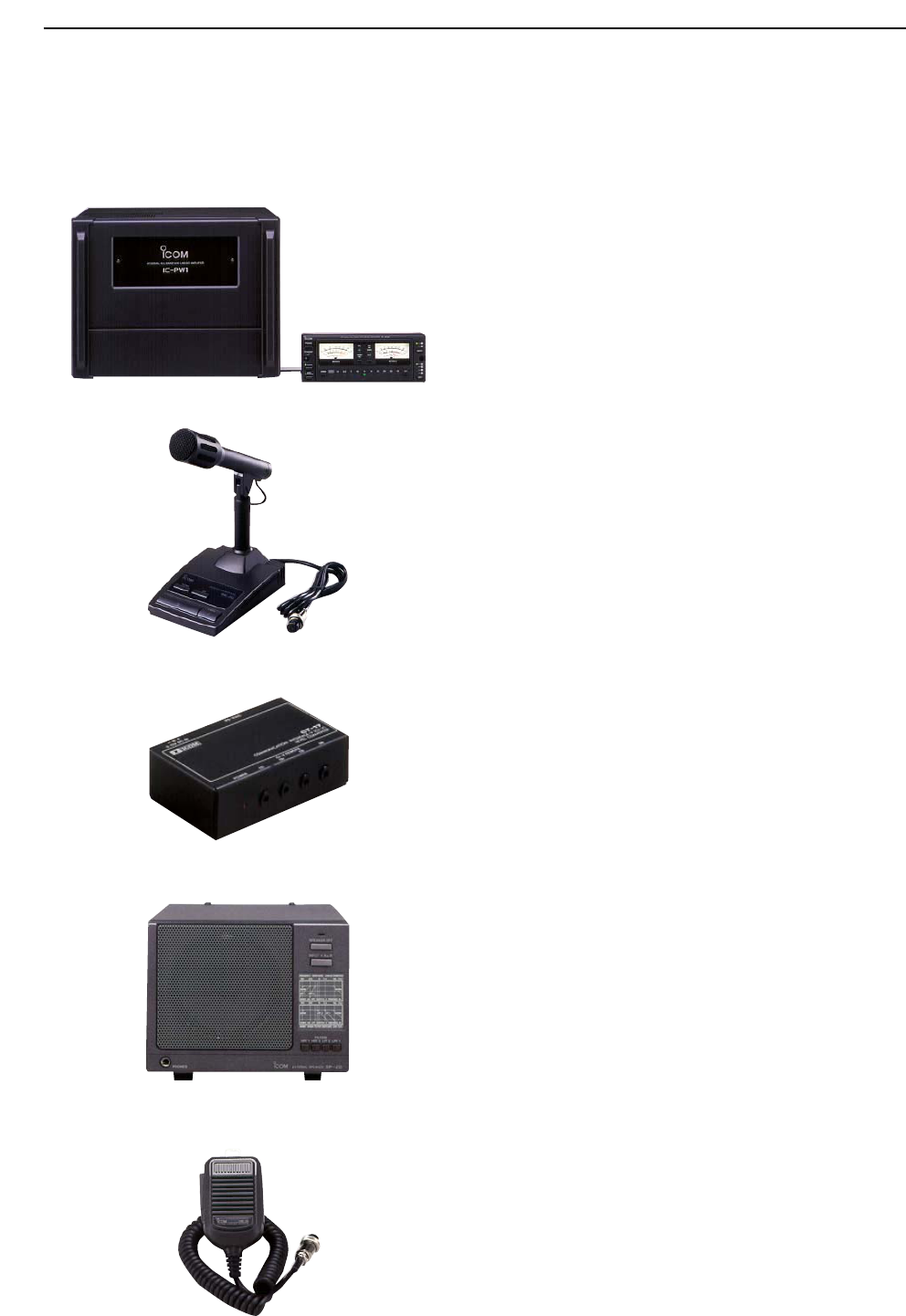
15-4
■Options
•IC-PW1 HF
/50
MH
z
ALL BAND
1k
W LINEAR AMPLIFIER
Full-duty 1 kW linear amplifier including an automatic
antenna tuner. Has automatic tuning and band selec-
tion capability. Full break-in (QSK) operation is possi-
ble. The amplifier/power supply unit and the remote
control unit are separated.
*The IC-PW1 does not comply with European Harmonised
Standard regulations. Please do not use this equipment
within European countries.
•SM-20 DESKTOP MICROPHONE
Unidirectional, electret microphone for base station
operation. Includes [UP]/[DOWN] switches and a low
cut function.
•CT-17 CI-V LEVEL CONVERTER
For remote transceiver control using a PC. You can
change frequencies, operating mode, memory chan-
nels, etc. (software is not included)
•SP-20 EXTERNAL SPEAKER
4 audio filters; headphone jack; can connect to 2
transceivers.
• Input impedance : 8 Ω
• Max. input power : 5 W
•HM-36 HAND MICROPHONE
Hand microphone equipped with [UP]/[DOWN] switch-
es.
15 SPECIFICATIONS AND OPTIONS

Please record the serial number of your IC-7800 transceiver below for future servicing
reference:
Serial Number :
Date of purchase :
Place where purchased :

1-1-32 Kamiminami, Hirano-ku, Osaka 547-0003, Japan