ICOM orporated 259000 Amateur HF Scanning Transceiver User Manual IC 7800 Eng
ICOM Incorporated Amateur HF Scanning Transceiver IC 7800 Eng
Contents
- 1. Users Manual Part 1
- 2. Users Manual Part 2
- 3. Users Manual Part 3
- 4. Users Manual Part 4
- 5. Users Manual Part 5
Users Manual Part 3

5-1
FUNCTIONS FOR RECEIVE Section 5
■Spectrum scope screen ……………………………………………… 5-2
DCenter mode ………………………………………………………… 5-2
DFix mode ……………………………………………………………… 5-3
DMini scope screen indication ……………………………………… 5-4
DScope set mode ……………………………………………………… 5-4
■Preamplifier ……………………………………………………………… 5-9
■Attenuator ……………………………………………………………… 5-9
■RIT function …………………………………………………………… 5-10
DRIT monitor function …………………………………………………5-10
■AGC function …………………………………………………………… 5-11
DSelecting the preset value …………………………………………5-11
DAdjusting the AGC time constant …………………………………5-11
DSetting the AGC time constant preset value ………………………5-11
■Twin PBT operation …………………………………………………… 5-12
■IF filter selection ……………………………………………………… 5-13
DIF filter selection …………………………………………………… 5-13
DFilter passband width setting (except FM mode) ……………… 5-13
DRoofing filter selection ……………………………………………… 5-14
DDSP filter shape …………………………………………………… 5-14
DFilter shape set mode ……………………………………………… 5-14
■Dualwatch operation ………………………………………………… 5-16
■Noise blanker ………………………………………………………… 5-17
DNB set mode ………………………………………………………… 5-17
■Noise reduction ………………………………………………………… 5-18
■Dial lock function ……………………………………………………… 5-18
■Notch function ………………………………………………………… 5-19
■Digital selector ………………………………………………………… 5-19
5-2
■Spectrum scope screen
This function allows you to display the conditions of the
selected band, as well as relative strengths of signals.
The IC-7800 has two modes for the spectrum indica-
tion— one is center mode, and anther one is fix mode.
In addition, the IC-7800 has a mini scope screen for
regular scope indication.
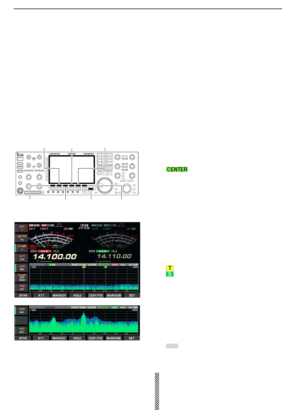
DCenter mode
Displays signals around the set frequency within the
selected span. The set frequency is always displayed
at the center of the screen.
qPush [EXIT/SET] several times to close a multi-
function screen, if necessary.
wPush [F-1•SCOPE] to select the scope screen.
ePush [F-5•CENT/FIX] to select the center mode.
• “ ” is displayed when center mode is selected.
rPush [F-1•SPAN] several times to select the scope
span.
• ±2.5, ±5.0, ±10, ±25, ±50, ±100 and ±250 kHz are avail-
able.
• Sweeping speed is selectable for each span indepen-
dently in scope set mode. (pgs. 5-5, 5-6)
tPush [F-2•ATT] several times to activate an attenu-
ator or turn the attenuator OFF.
• 10, 20 and 30 dB attenuators are available.
yPush [F-6•MAIN/SUB] to select main band.
• The spectrum scope with sub band selection is activated
during dualwatch or split frequency operation only.
uPush [F-3•MARKER] several times to select the
marker (sub readout or transmit frequency) or turn
the marker OFF.
• “ ” displays the marker at the transmit frequency.
• “ ” displays the marker at the sub readout frequency.
• “<<” or “>>” appears when the marker is out of range.
• The spectrum scope shows the transmit signal wave-
form while transmitting. This can be deactivated in
scope set mode. (p. 5-4)
• The spectrum scope shows the peak level holding func-
tion. Peak levels are displayed in the background of the
current spectrum in a different color until the receive fre-
quency changes. This can be deactivated and the wave-
form color can be set in scope set mode. (p. 5-5)
iPush [F-4•HOLD] to freeze the current spectrum
waveform.
• “ ” appears while the function is in use.
• The peak hold function can be deactivated in scope set
mode.
oPush [EXIT/SET] to exit the scope screen.
NOTE: If a strong signal is received, a ghost wave-
form may appear. Push [F-2•ATT] several times to
activate the spectrum scope attenuator in this case.
Spurious signal waveform may be displayed. They
are made in internal scope circuit and does not indi-
cate a transceiver malfunction.
HOLD
[F-3•MARKER]
[F-2•ATT]
[F-1•SPAN] [EXIT/SET]
[F-5•CENT/FIX][F-4•HOLD]
[F-6•MAIN/SUB]
5FUNCTIONS FOR RECEIVE
• Observed indication example
5-3
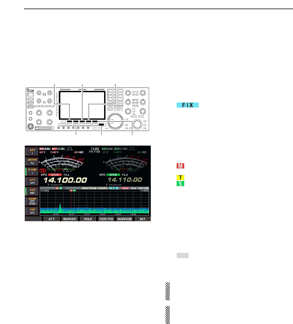
DFix mode
Displays signals within the specified frequency range.
The selected frequency band conditions can be
grasped at a glance when using this mode.
qPush [EXIT/SET] several times to close a multi-
function screen, if necessary.
wPush [F-1•SCOPE] to select the scope screen.
ePush [F-5•CENT/FIX] to select the fix mode.
• “ ” is displayed when fix mode is selected.
rPush [F-2•ATT] several times to activate an attenu-
ator or turn the attenuator OFF.
• 10, 20 and 30 dB attenuators are available.
tPush [F-6•MAIN/SUB] to select main band.
• The spectrum scope with sub band selection is activated
during dualwatch or split frequency operation only.
yPush [F-3•MARKER] several times to select the
marker (sub readout or transmit frequency) or turn
the marker OFF.
• “ ” displays the marker at the main readout frequency.
(always displayed)
• “ ” displays the marker at the transmit frequency.
• “ ” displays the marker at the sub readout frequency.
• “<<” or “>>” appears when the marker is out of range.
• The spectrum scope shows the transmit signal wave-
form while transmitting. This can be deactivated in
scope set mode. (p. 5-4)
• The spectrum scope shows the peak level holding func-
tion. Peak levels are displayed in the background of the
current spectrum in a different color until the receive fre-
quency changes. This can be deactivated and the wave-
form color can be set in scope set mode. (p. 5-5)
uPush [F-4•HOLD] to freeze the current spectrum
waveform.
• “ ” appears while the function is in use.
• The peak hold function can be deactivated in scope set
mode.
iPush [EXIT/SET] to exit the scope screen.
NOTE: If a strong signal is received, a ghost wave-
form may appear. Push [F-2•ATT] several times to
activate the spectrum scope attenuator in this case.
The scope band width can be specified for each op-
erating frequency band independently in scope set
mode. (pgs. 5-6 to 5-8)
HOLD
[F-3•MARKER]
[F-2•ATT]
[EXIT/SET]
[F-5•CENT/FIX][F-4•HOLD]
[F-6•MAIN/SUB]
5
FUNCTIONS FOR RECEIVE
5-4
DMini scope screen indication
The mini scope screen can be displayed with another
screen indication, such as set mode menu, decoder
screen, memory list screen, etc. simultaneously.
qSet the scope mode (center or fix), marker, attenu-
ator, span, etc. in advance. (pgs. 5-2, 5-3)
wPush [M.SCOPE] to toggle the mini scope indica-
tion ON and OFF.
• The S/RF meter type during mini scope indication can
be selected in display set mode (Meter Type (Wide
Screen) item). (p. 12-11)
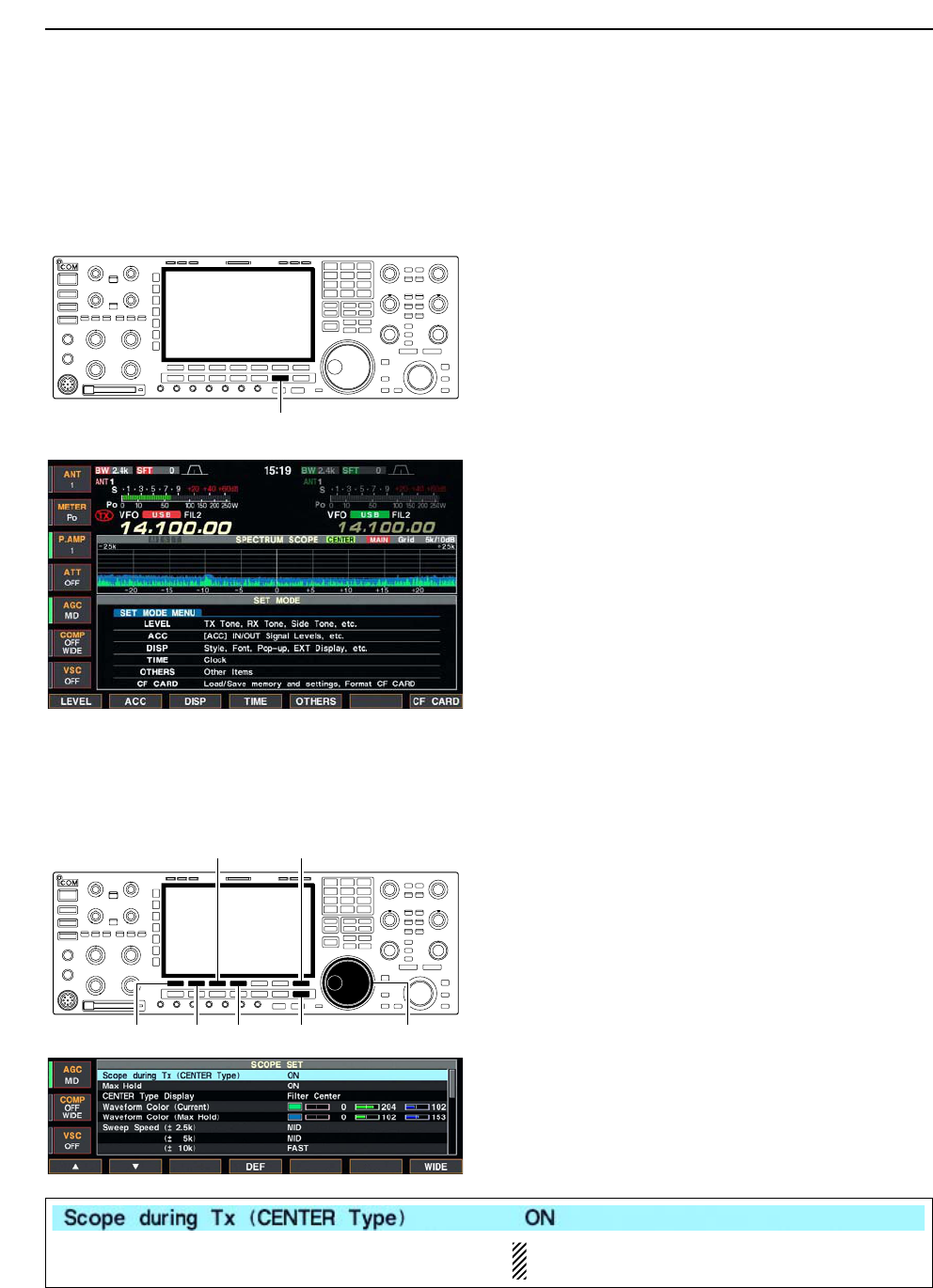
DScope set mode
This set mode is used to set the waveform color,
sweeping speed, scope range for fix mode, etc.
qDuring spectrum scope indication ON, push
[F-7•SET] to select scope set mode screen.
• Push [F-7•WIDE] to toggle the screen size between nor-
mal and wide.
wPush [F-1•Y] or [F-2•Z] to select the desired set
item.
eSet the desired condition using the main dial.
• Push [F-4•DEF] for 1 sec. to select the default condition
or value.
• Push [F-3•Ω≈] to select the set contents for some
items.
rPush [EXIT/SET] to exit from set mode.
[F-1•Y] Main dial[EXIT/SET][F-2•Z][F-4•DEF]
[F-3•Ω ≈] [F-7•WIDE]
[M.SCOPE]
5FUNCTIONS FOR RECEIVE
Turn the transmitting signal waveform indication ON
and OFF.
NOTE: The transmitting signal waveform indica-
tion is available for the center mode only.
5-5
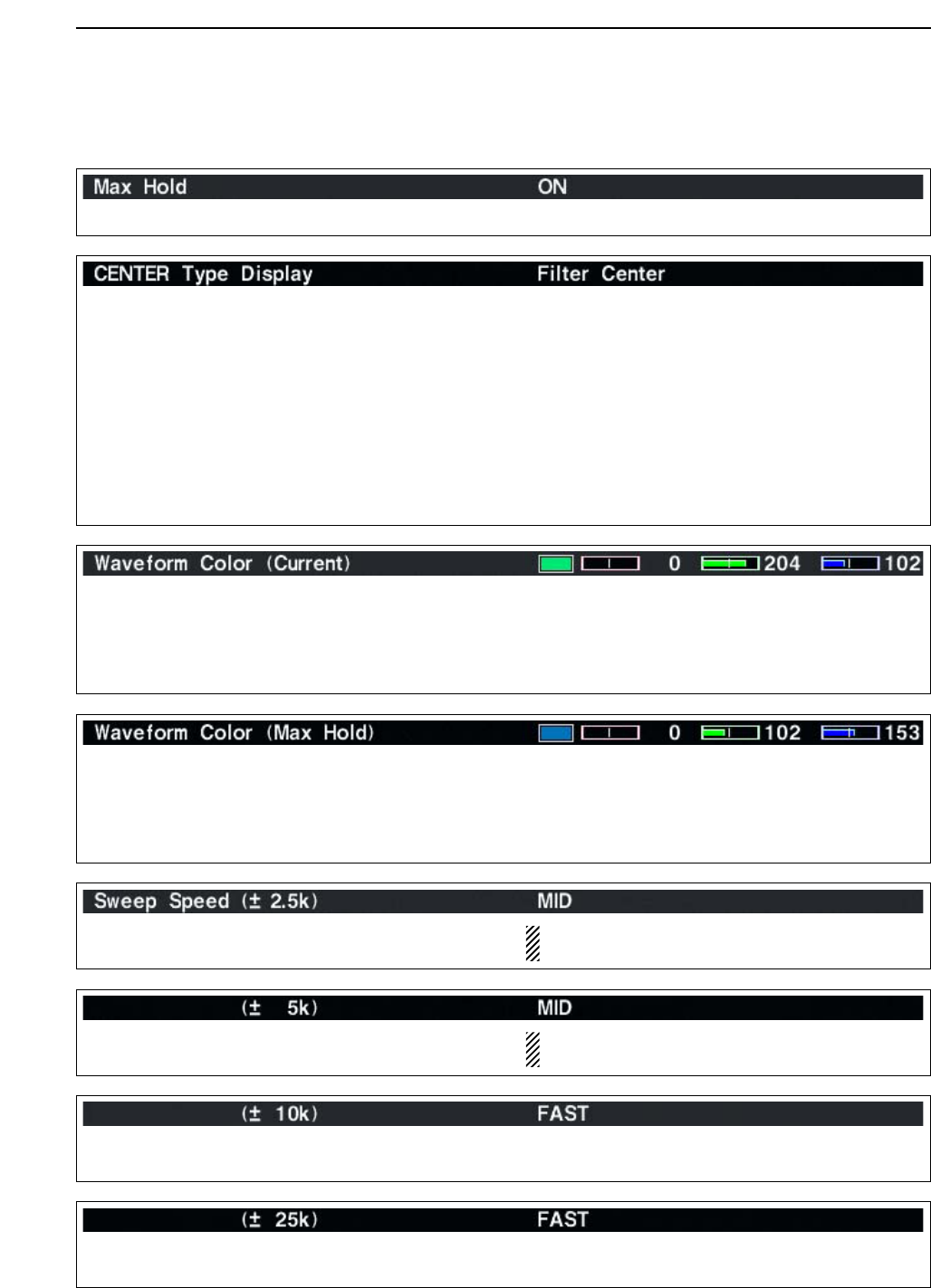
DScope set mode (continued)
5
FUNCTIONS FOR RECEIVE
Turn the peak level holding function ON and OFF.
Select the center frequency of the spectrum scope
indication (center mode only).
• Filter center : Shows the selected filter’s center
frequency at the center.
• Carrier Point Center
: Shows the selected operating
mode carrier point frequency at
the center.
• Carrier Point Center (Abs. Freq.)
: In addition to the carrier point
center setting above, the actual
frequency is displayed for the
bottom of the scope.
Set the waveform color for the currently receiving sig-
nals.
• The color is set in RGB format.
• Push [F-3•Ω≈] to select R (Red), G (Green) and B
(Blue), and rotate the ratio from 0 to 255 range.
• The set color is indicated in the box beside the RGB
scale.
Set the waveform color for the receiving signals max-
imum level.
• The color is set in RGB format.
• Push [F-3•Ω≈] to select R (Red), G (Green) and B
(Blue), and rotate the ratio from 0 to 255 range.
• The set color is indicated in the box beside the RGB
scale.
Select the sweeping speed for the ±2.5 kHz span
selection from SLOW, MID and FAST.
NOTE: The waveform may be displayed incorrect-
ly with “FAST” setting.
Select the sweeping speed for the ±5 kHz span
selection from SLOW, MID and FAST.
NOTE: The waveform may be displayed incorrect-
ly with “FAST” setting.
Select the sweeping speed for the ±10 kHz span
selection from SLOW, MID and FAST.
Select the sweeping speed for the ±25 kHz span
selection from SLOW, MID and FAST.
5-6
DScope set mode (continued)
5FUNCTIONS FOR RECEIVE
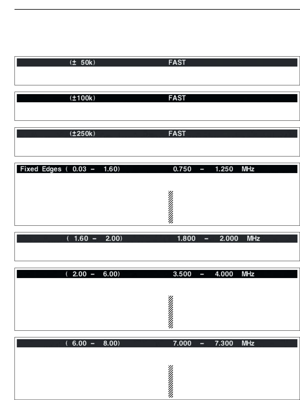
Select the sweeping speed for the ±50 kHz span
selection from SLOW, MID and FAST.
Select the sweeping speed for the ±100 kHz span
selection from SLOW, MID and FAST.
Select the sweeping speed for the ±250 kHz span
selection from SLOW, MID and FAST.
Set the scope edge frequencies for fix mode scope
with below 1.6 MHz band selection.
• Set the frequencies within 0.030 to 1.600 MHz
range in 1 kHz steps.
Up to 500 kHz band width can be specified, so
either edge frequency will be set to the differ-
ence between higher and lower frequencies
become 5 to 500 kHz automatically while setting
another edge frequency.
Set the scope edge frequencies for fix mode scope
when 1.6 to 2 MHz band is selected.
• Set the frequencies within 1.600 to 2.000 MHz
range in 1 kHz steps.
Set the scope edge frequencies for fix mode scope
when 2 to 6 MHz band is selected.
• Set the frequencies within 2.000 to 6.000 MHz
range in 1 kHz steps.
Up to 500 kHz band width can be specified, so
either edge frequency will be set to the differ-
ence between higher and lower frequencies
become 5 to 500 kHz automatically while setting
another edge frequency.
Set the scope edge frequencies for fix mode scope
when 6 to 8 MHz band is selected.
• Set the frequencies within 6.000 to 8.000 MHz
range in 1 kHz steps.
Up to 500 kHz band width can be specified, so
either edge frequency will be set to the differ-
ence between higher and lower frequencies
become 5 to 500 kHz automatically while setting
another edge frequency.
5-7
DScope set mode (continued)
5
FUNCTIONS FOR RECEIVE
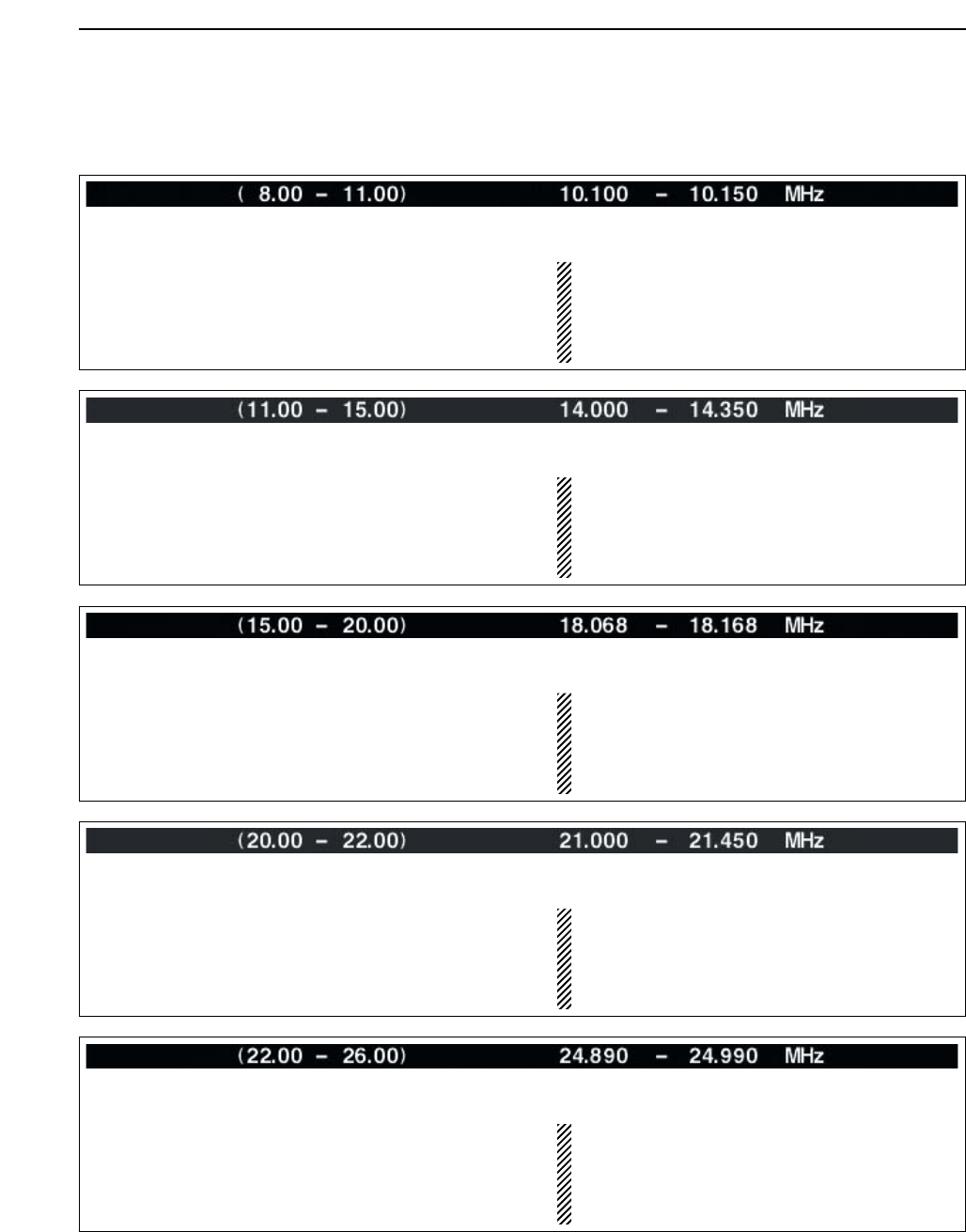
Set the scope edge frequencies for fix mode scope
when 8 to 11 MHz band is selected.
• Set the frequencies within 8.000 to 11.000 MHz
range in 1 kHz steps.
Up to 500 kHz band width can be specified, so
either edge frequency will be set to the differ-
ence between higher and lower frequencies
become 5 to 500 kHz automatically while setting
another edge frequency.
Set the scope edge frequencies for fix mode scope
when 11 to 15 MHz band is selected.
• Set the frequencies within 11.000 to 15.000 MHz
range in 1 kHz steps.
Up to 500 kHz band width can be specified, so
either edge frequency will be set to the differ-
ence between higher and lower frequencies
become 5 to 500 kHz automatically while setting
another edge frequency.
Set the scope edge frequencies for fix mode scope
when 15 to 20 MHz band is selected.
• Set the frequencies within 15.000 to 20.000 MHz
range in 1 kHz steps.
Up to 500 kHz band width can be specified, so
either edge frequency will be set to the differ-
ence between higher and lower frequencies
become 5 to 500 kHz automatically while setting
another edge frequency.
Set the scope edge frequencies for fix mode scope
when 20 to 22 MHz band is selected.
• Set the frequencies within 20.000 to 22.000 MHz
range in 1 kHz steps.
Up to 500 kHz band width can be specified, so
either edge frequency will be set to the differ-
ence between higher and lower frequencies
become 5 to 500 kHz automatically while setting
another edge frequency.
Set the scope edge frequencies for fix mode scope
when 22 to 26 MHz band is selected.
• Set the frequencies within 22.000 to 26.000 MHz
range in 1 kHz steps.
Up to 500 kHz band width can be specified, so
either edge frequency will be set to the differ-
ence between higher and lower frequencies
become 5 to 500 kHz automatically while setting
another edge frequency.
5-8
DScope set mode (continued)
5FUNCTIONS FOR RECEIVE
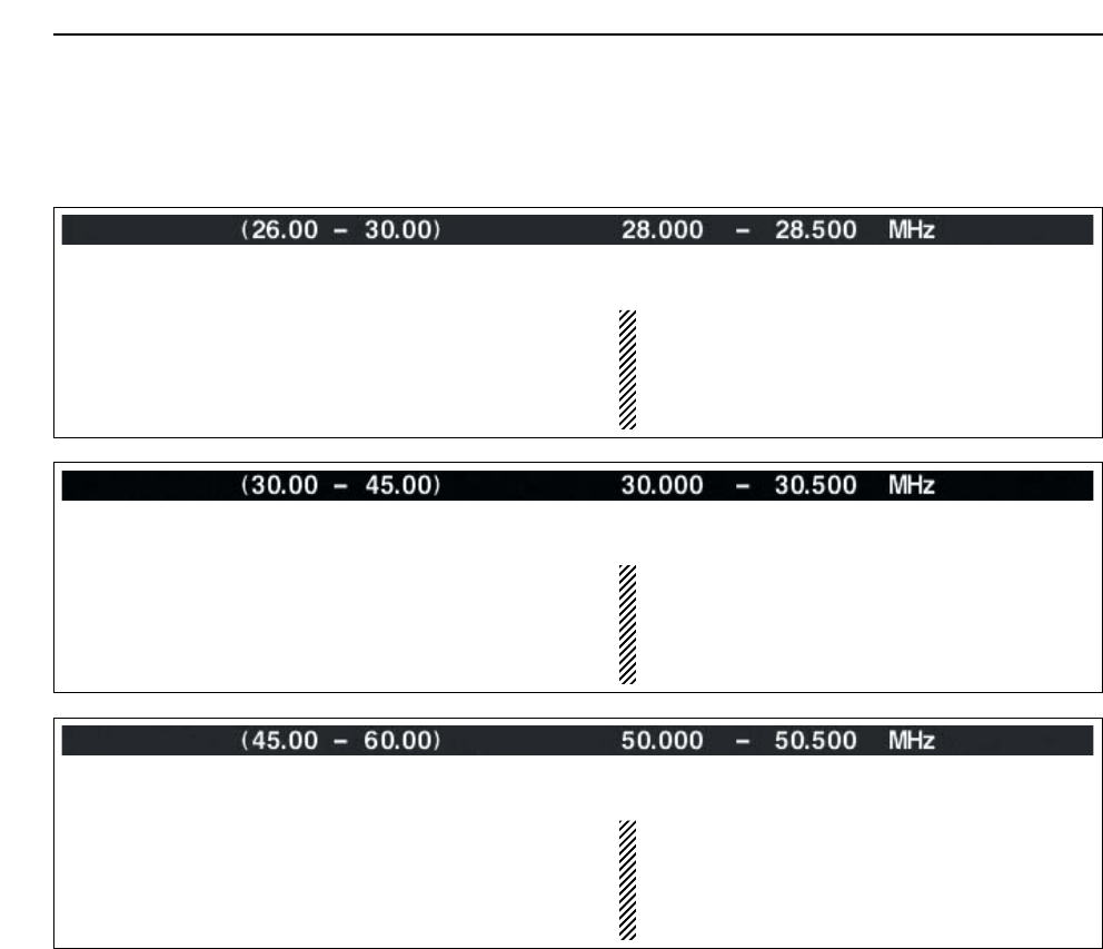
Set the scope edge frequencies for fix mode scope
when 30 to 45 MHz band is selected.
• Set the frequencies within 30.000 to 45.000 MHz
range in 1 kHz steps.
Up to 500 kHz band width can be specified, so
either edge frequency will be set to the differ-
ence between higher and lower frequencies
become 5 to 500 kHz automatically while setting
another edge frequency.
Set the scope edge frequencies for fix mode scope
when 45 to 60 MHz band is selected.
• Set the frequencies within 45.000 to 60.000 MHz
range in 1 kHz steps.
Up to 500 kHz band width can be specified, so
either edge frequency will be set to the differ-
ence between higher and lower frequencies
become 5 to 500 kHz automatically while setting
another edge frequency.
Set the scope edge frequencies for fix mode scope
when 26 to 30 MHz band is selected.
• Set the frequencies within 26.000 to 30.000 MHz
range in 1 kHz steps.
Up to 500 kHz band width can be specified, so
either edge frequency will be set to the differ-
ence between higher and lower frequencies
become 5 to 500 kHz automatically while setting
another edge frequency.
5-9
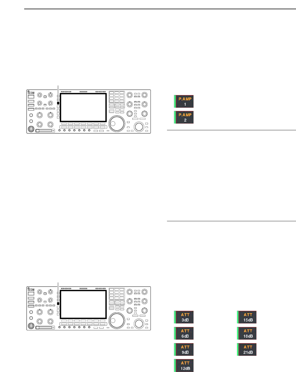
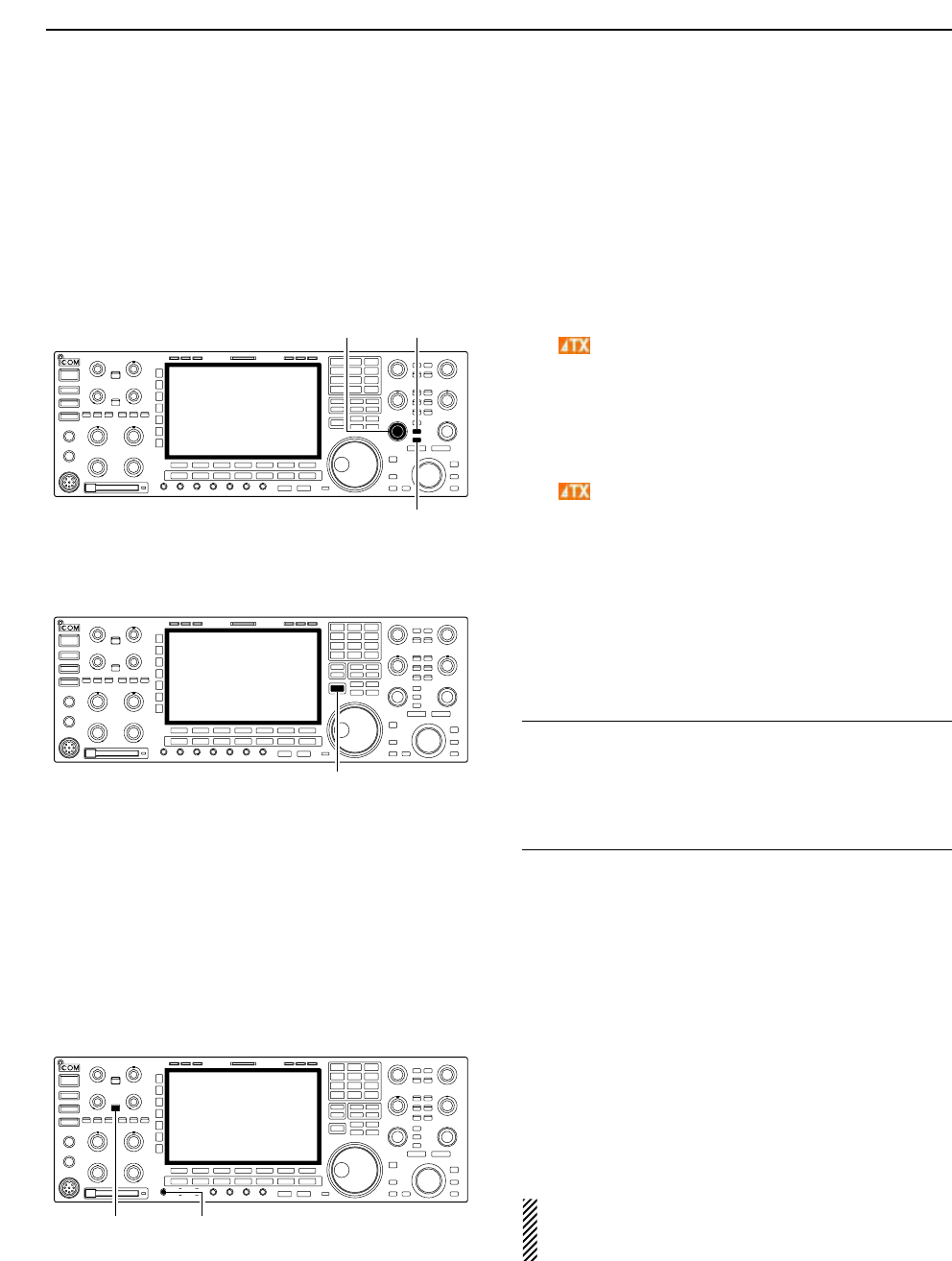
■Preamplifier
The preamp amplifies received signals in the front end
circuit to improve the S/N ratio and sensitivity. Set this
to preamp 1 or preamp 2 when receiving weak signals.
➥Push [P.AMP] several times to set the preamp OFF,
preamp 1 ON or preamp 2 ON.
For all HF bands
High gain preamp for 24 MHz band and
above
✔
About the “P.AMP2”
The “P.AMP 2” is a high gain receive amplifier. When
the “P.AMP 2” is used during times of strong electric
fields, distortion sometimes results. In such cases, use
the transceiver with the “P.AMP 1” or “P.AMP OFF” set-
ting.
The “P.AMP 2” is most effective when:
• Used on bands above 24 MHz and when electric
fields are weak.
• Receive sensitivity is insufficient during low gain, or
while using a narrow band antenna (such as small
loop, a Beverage antenna or a short Yagi antenna,
etc.) is used.
■Attenuator
The attenuator prevents a desired signal from distor-
tion when very strong signals are near the desired fre-
quency or when very strong electric fields, such as
from broadcasting stations, are near your location.
➥Push [ATT] several times to set the attenuator 6 dB,
12 dB, 18 dB or attenuator OFF.
➥Push [ATT] for 1 sec. several times to set the atten-
uator 3 dB, 6 dB, 9 dB, 12 dB, 15 dB, 18 dB, 21 dB
or attenuator OFF.
[ATT]
[P.AMP]
5
FUNCTIONS FOR RECEIVE
3dB
attenuation
6dB
attenuation
9dB
attenuation
12 dB
attenuation
15 dB
attenuation
18 dB
attenuation
21 dB
attenuation
5-10
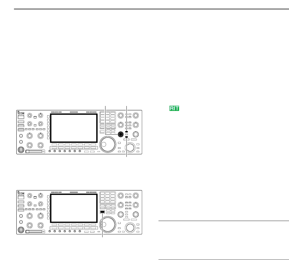
■RIT function
The RIT (Receive Increment Tuning) function com-
pensates for off-frequencies of the communicating
station.
The function shifts the receive frequency up to
±9.99 kHz in 10 Hz steps without moving the transmit
frequency.
qPush [RIT] to turn the RIT function ON and OFF.
• “ ” and the shifting frequency appear when the func-
tion is ON.
wRotate the [RIT/∂TX] control.
• Push [CLEAR] for 1 sec. to reset the RIT frequency.
• Push [CLEAR] momentarily to reset the RIT frequency
when the quick RIT/∂TX clear function is ON. (p. 12-17)
• Push [RIT] for 1 sec. to add the shift frequency to the op-
erating frequency.
DRIT monitor function
When the RIT function is ON, pushing and holding
[XFC] allows you to monitor the operating frequency
directly (RIT is temporarily cancelled).
✔
For your convenience— Calculate function
The shift frequency of the RIT function can be
added/subtracted to the displayed frequency.
➥While displaying the RIT shift frequency, push [RIT]
for 1 sec.
[XFC]
[RIT][RIT/∂TX]
[CLEAR]
5FUNCTIONS FOR RECEIVE
5-11
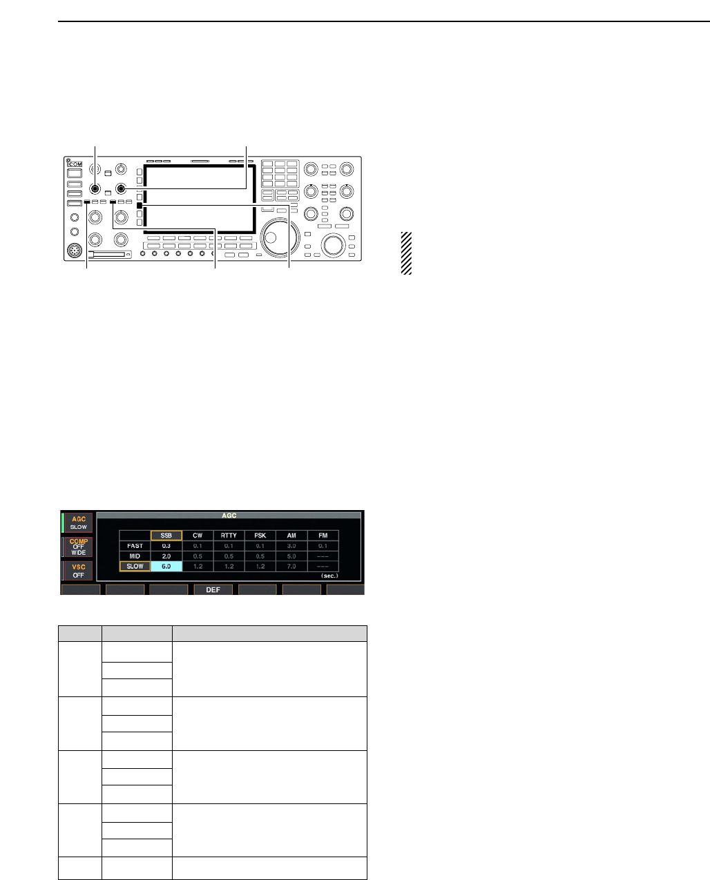
■AGC function
The AGC (auto gain control) controls receiver gain to
produce a constant audio output level even when the
received signal strength is varied by fading, etc.
The transceiver has 3 AGC characteristics (time con-
stant; fast, mid, slow) for non-FM mode.
The FM mode AGC time constant is fixed as ‘FAST’
(0.1 sec.) and AGC time constant cannot be se-
lected.
DSelecting the preset value
qSelect non-FM mode.
wPush [AGC] several times to select AGC fast, AGC
medium (MID) or AGC slow.
DAdjusting the AGC time constant
qSelect non-FM mode.
wPush [AGC VR], then rotate [AGC] control to adjust
the AGC time constant.
• [AGC VR] indicator above the switch lights green.
DSetting the AGC time constant preset value
qSelect the desired mode except FM mode.
wPush [AGC] for 1 sec. to enter AGC set mode.
ePush [AGC] several times to select FAST time con-
stant.
rRotate the main dial to set the desired time constant
for ‘AGC FAST.’
• AGC time constant can be set between 0.1 to 8.0 sec.
(depends on mode) or turned OFF.
• Push [F-4•DEF] for 1 sec. to select a default value.
tPush [AGC] to select medium time constant.
yRotate the main dial to set the desired time constant
for ‘AGC MID.’
• AGC time constant can be set between 0.1 to 8.0 sec.
(depends on mode) or turned OFF.
• Push [F-4•DEF] for 1 sec. to select a default value.
uPush [AGC] to select slow time constant.
iRotate the main dial to set the desired time constant
for ‘AGC SLOW.’
• AGC time constant can be set between 0.1 to 8.0 sec.
(depends on mode) or turned OFF.
• Push [F-4•DEF] for 1 sec. to select a default value.
oSelect another mode except FM. Repeat steps eto
iif desired.
!0 Push [EXIT/SET] to exit the AGC set mode screen.
[AGC]
[AGC] control for main
[AGC VR] for main [AGC VR] for sub
[AGC] control for sub
5
FUNCTIONS FOR RECEIVE
Mode Default Selectable AGC time constant
0.3 (FAST) 0.1, 0.2, 0.3, 0.5, 0.8, 1.2, 1.6, 2.0,
SSB 2.0 (MID) 2.5, 3.0, 4.0, 5.0, 6.0
6.0 (SLOW)
0.1 (FAST) 0.1, 0.2, 0.3, 0.5, 0.8, 1.2, 1.6, 2.0,
CW 0.5 (MID) 2.5, 3.0, 4.0, 5.0, 6.0
1.2 (SLOW)
RTTY 0.1 (FAST) 0.1, 0.2, 0.3, 0.5, 0.8, 1.2, 1.6, 2.0,
PSK 0.5 (MID) 2.5, 3.0, 4.0, 5.0, 6.0
1.2 (SLOW)
3.0 (FAST) 0.3, 0.5, 0.8, 1.2, 1.6, 2.0, 2.5, 3.0,
AM 5.0 (MID) 4.0, 5.0, 6.0, 7.0, 8.0
7.0 (SLOW)
FM 0.1 (FAST) Fixed
• Selectable AGC time constant (unit: sec.)
5-12
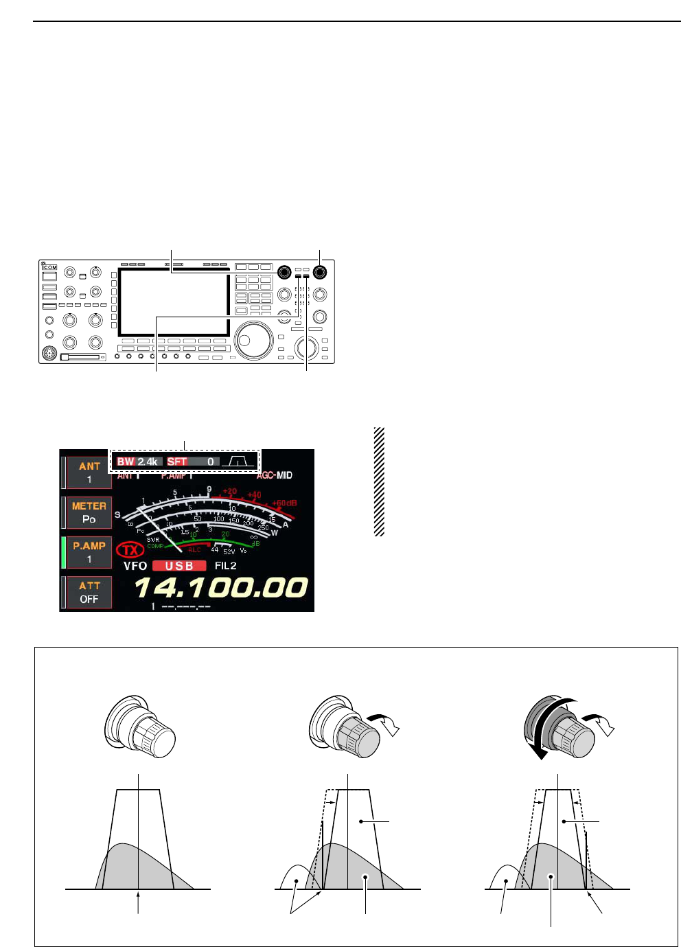
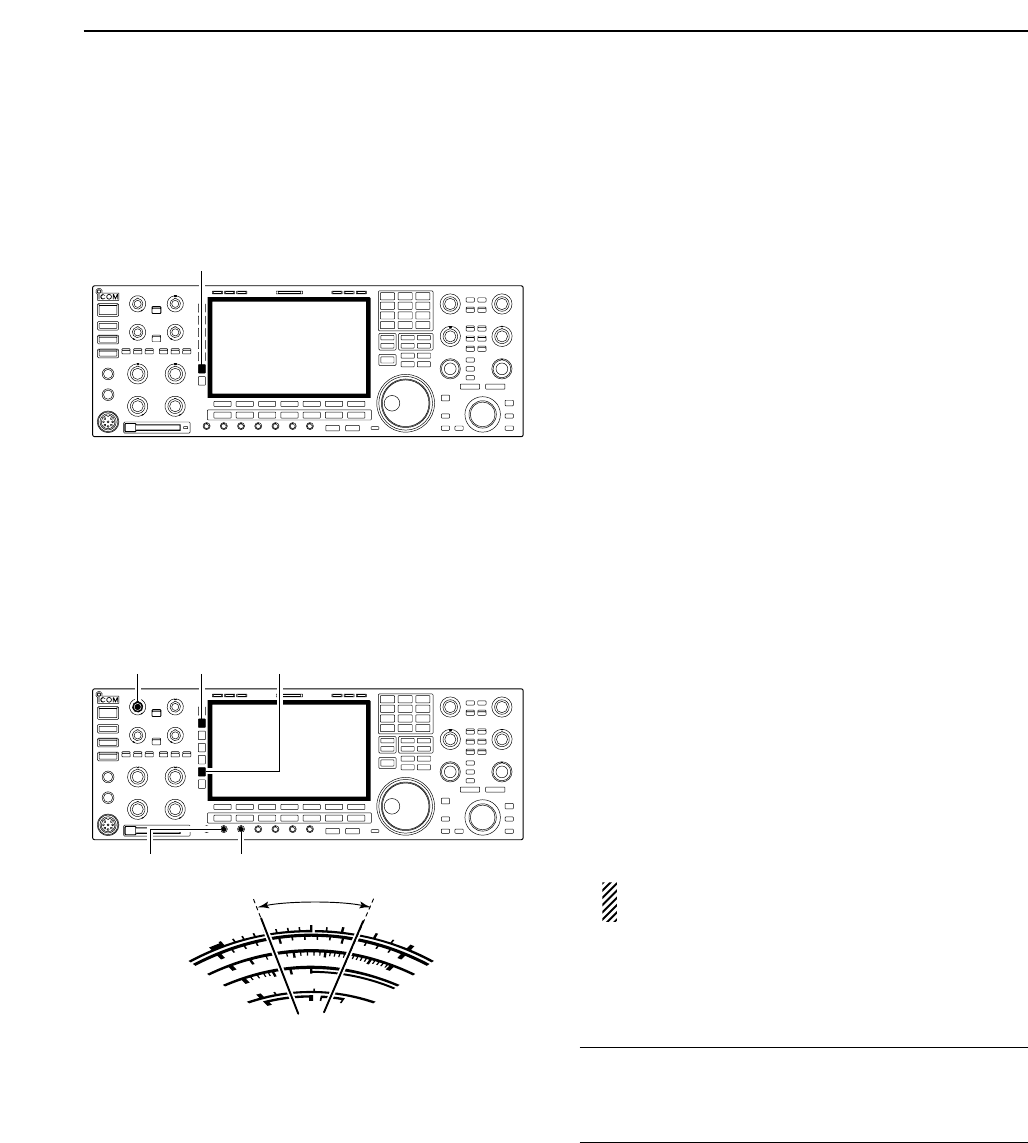
■Twin PBT operation
General PBT (Passband Tuning) function electronically
narrows the IF passband width by shifting the IF fre-
quency to slightly outside of the IF filter passband to
reject interference. This transceiver uses the DSP cir-
cuit for the PBT function. Moving both [TWIN PBT]
controls to the same position shifts the IF.
➥The LCD shows the passband width and shift fre-
quency graphically.
➥Push [FILTER] for 1 sec. to enter the filter set
screen. Current passband width and shift frequency
is displayed in the filter set screen.
➥To set the [TWIN PBT] controls to the center posi-
tions, push [PBT CLR] for 1 sec.
The variable range depends on the passband width
and mode. The edge of the variable range is half of the
passband width, and PBT is adjustable in 25 or 50 Hz
steps.
• [TWIN PBT] should normally be set to the center posi-
tions (PBT setting is cleared) when there is no interfer-
ence.
• When PBT is used, the audio tone may be changed.
• Not available for FM mode.
• While rotating [TWIN PBT], noise may occur. This comes
from the DSP unit and does not indicate an equipment
malfunction.
• PBT operation example
IF center frequency Interference Desired signal
Passband
Both controls at
center position
Cutting a lower
passband
Cutting both higher and
lower passbands
Interference Interference
Desired signal
Passband
PBT1
PBT2
PBT1
PBT2
PBT1
PBT2
Shows filter width, shifting value and condition
[TWIN PBT] for main
[PBT CLEAR] for main [PBT CLEAR] for sub
[TWIN PBT] for sub
5FUNCTIONS FOR RECEIVE
5-13
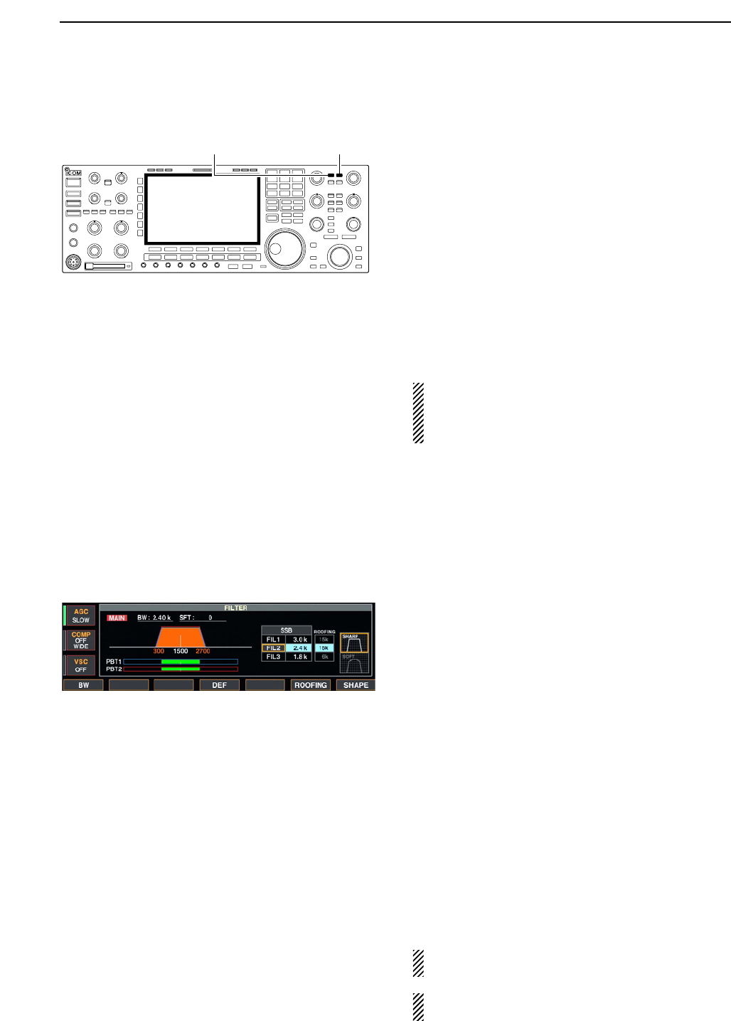
■IF filter selection
The transceiver has 3 passband width IF filters for
each mode.
For SSB, CW and PSK modes, the passband width
can be set within 50 to 3600 Hz in 50 or 100 Hz steps.
A total of 41 passband widths are available.
For RTTY mode, the passband width can be set within
50 to 2700 Hz in 50 or 100 Hz steps. A total of 32 pass-
band widths are available.
For AM mode, the passband width can be set within
200 Hz to 10 kHz in 200 Hz steps. A total of 50 pass-
band widths are available.
For FM mode, the passband width is fixed and 3 pass-
band widths are available.
The filter selection is automatically memorized in
each mode.
The PBT shift frequencies are automatically memo-
rized in each filter.
DIF filter selection
qSelect the desired mode.
wPush [FILTER] several times to select the IF filter 1,
2 or 3.
• The selected passband width and filter number is dis-
played in the LCD.
DFilter passband width setting (except FM mode)
qPush [FILTER] for 1 sec. to enter filter set screen.
wSelect any mode except FM.
• Passband widths for FM modes are fixed and cannot be
set.
ePush [FILTER] several times to select the desired IF
filter.
rWhile pushing [F-1•BW], rotate the main dial to set
the desired passband width.
• In SSB, CW and PSK modes, the passband width can
be set within the following range.
50 to 500 Hz 50 Hz steps
600 to 3600 Hz 100 Hz steps
• In RTTY mode, the passband width can be set within the
following range.
50 to 500 Hz 50 Hz steps
600 to 2700 Hz 100 Hz steps
• In AM mode, the passband width can be set within the
following range.
200 Hz to 10 kHz 200 Hz steps
• Push [F-4•DEF] for 1 sec. to select the default value.
tRepeat steps wto rif desired.
yPush [EXIT/SET] to exit filter set screen.
The PBT shift frequencies are cleared when the
passband width is changed.
This filter set screen graphically displays the PBT
shift frequencies and CW pitch operations.
[FILTER] for main [FILTER] for sub
5
FUNCTIONS FOR RECEIVE
5-14
DRoofing filter selection
The IC-7800 has 6 kHz roofing filter. The roofing filter
allows you an interference reduction from nearby
strong signals.
qPush [FILTER] for 1 sec. to enter filter set screen.
wSelect any mode except FM.
ePush [F-6•ROOFING] to select the desired filter
from 15 kHz (regular 1st IF filter) and 6 kHz (roofing fil-
ter).
• Push [F-4•DEF] for 1 sec. to select a default value.
rPush [EXIT•SET] to exit filter set screen.
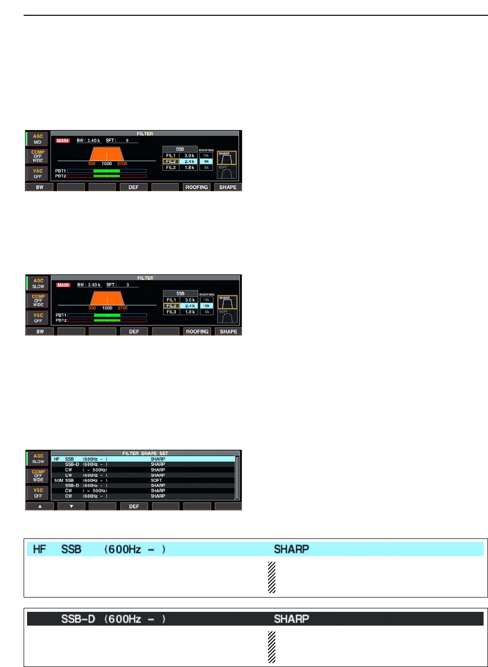
DDSP filter shape
The type of DSP filter shape for each SSB, SSB data
and CW can be selected independently from soft and
sharp.
qPush [FILTER] for 1 sec. to enter filter set screen.
wSelect SSB, SSB data or CW mode.
ePush [F-7•SHAPE] to select the desired filter shape
from soft and sharp.
rPush [EXIT•SET] to exit filter set screen.
The filter shape can be set for each band (HF and
50 MHz bands), mode, as well as the passband width
setting (CW only) independently as your default setting
in filter shape set mode.
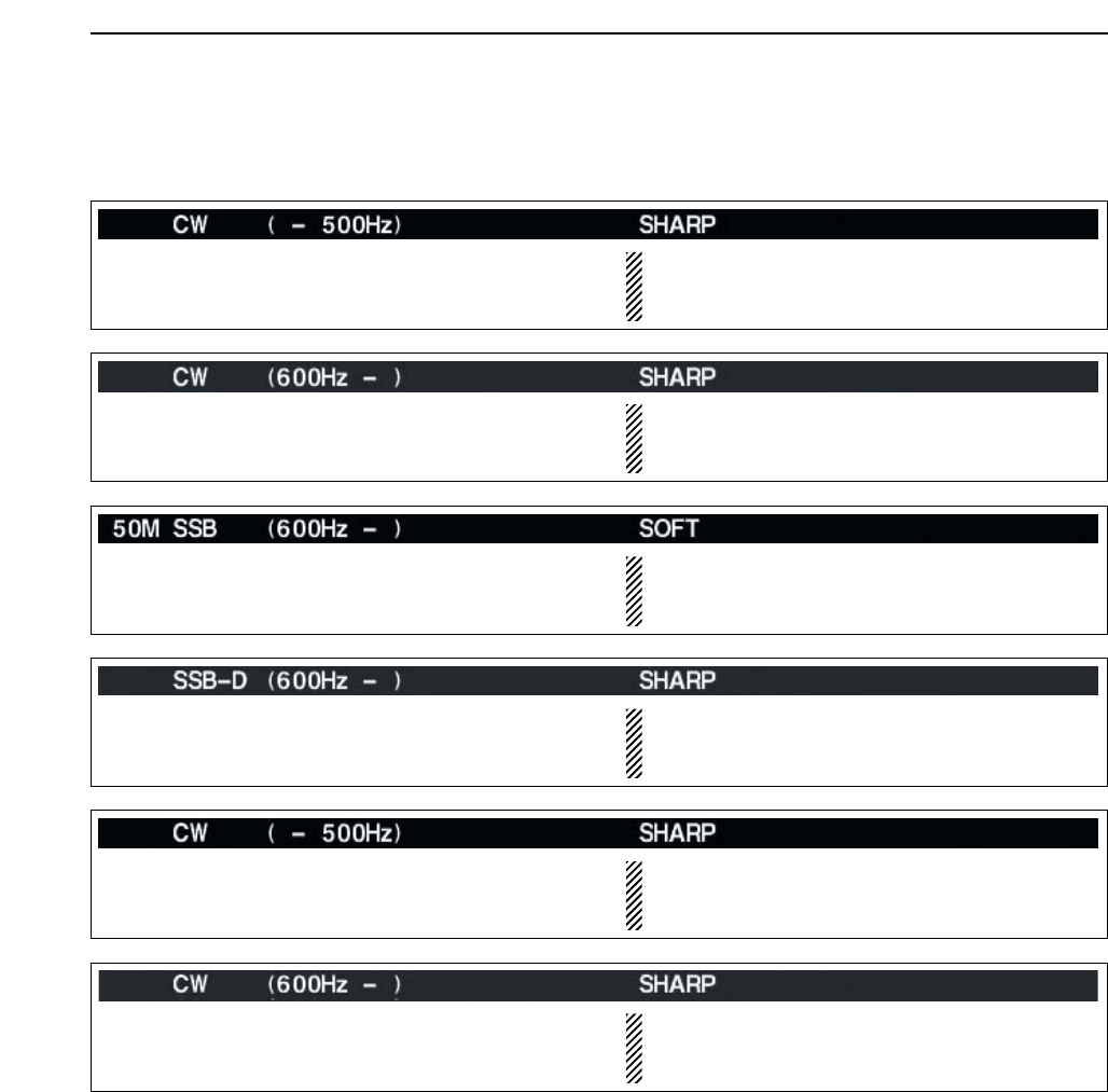
DFilter shape set mode
The type of DSP filter shape for each SSB, SSB data
and CW can be selected independently from soft and
sharp.
qPush [FILTER] for 1 sec. to enter filter set screen.
wPush [F-7•SHAPE] for 1 sec. to enter filter shape set
mode.
ePush [F-1•Y] or [F-2•Z] to select the desired item.
rRotate the main dial to select the filter shape from
soft and sharp.
tPush [EXIT/SET] to exit filter shape set mode.
5FUNCTIONS FOR RECEIVE
Select the filter shape for SSB mode in HF bands. The set filter shape is automatically used only
when the IF filter that 600 Hz or wider setting is
set.
Select the filter shape for SSB data mode in HF
bands.
The set filter shape is automatically used only
when the IF filter that 600 Hz or wider setting is
set.
5-15
DFilter shape set mode (continued)
5
FUNCTIONS FOR RECEIVE
Select the filter shape for CW mode in HF bands. The set filter shape is automatically used only
when the IF filter that 500 Hz or narrower setting is
set.
Select the filter shape for CW mode in HF bands. The set filter shape is automatically used only
when the IF filter that 600 Hz or wider setting is
set.
Select the filter shape for SSB mode in 50 MHz band. The set filter shape is automatically used only
when the IF filter that 600 Hz or wider setting is
set.
Select the filter shape for SSB data mode in 50 MHz
band.
The set filter shape is automatically used only
when the IF filter that 600 Hz or wider setting is
set.
Select the filter shape for CW mode in 50 MHz band. The set filter shape is automatically used only
when the IF filter that 500 Hz or narrower setting is
set.
Select the filter shape for CW mode in 50 MHz band. The set filter shape is automatically used only
when the IF filter that 600 Hz or wider setting is
set.
5-16
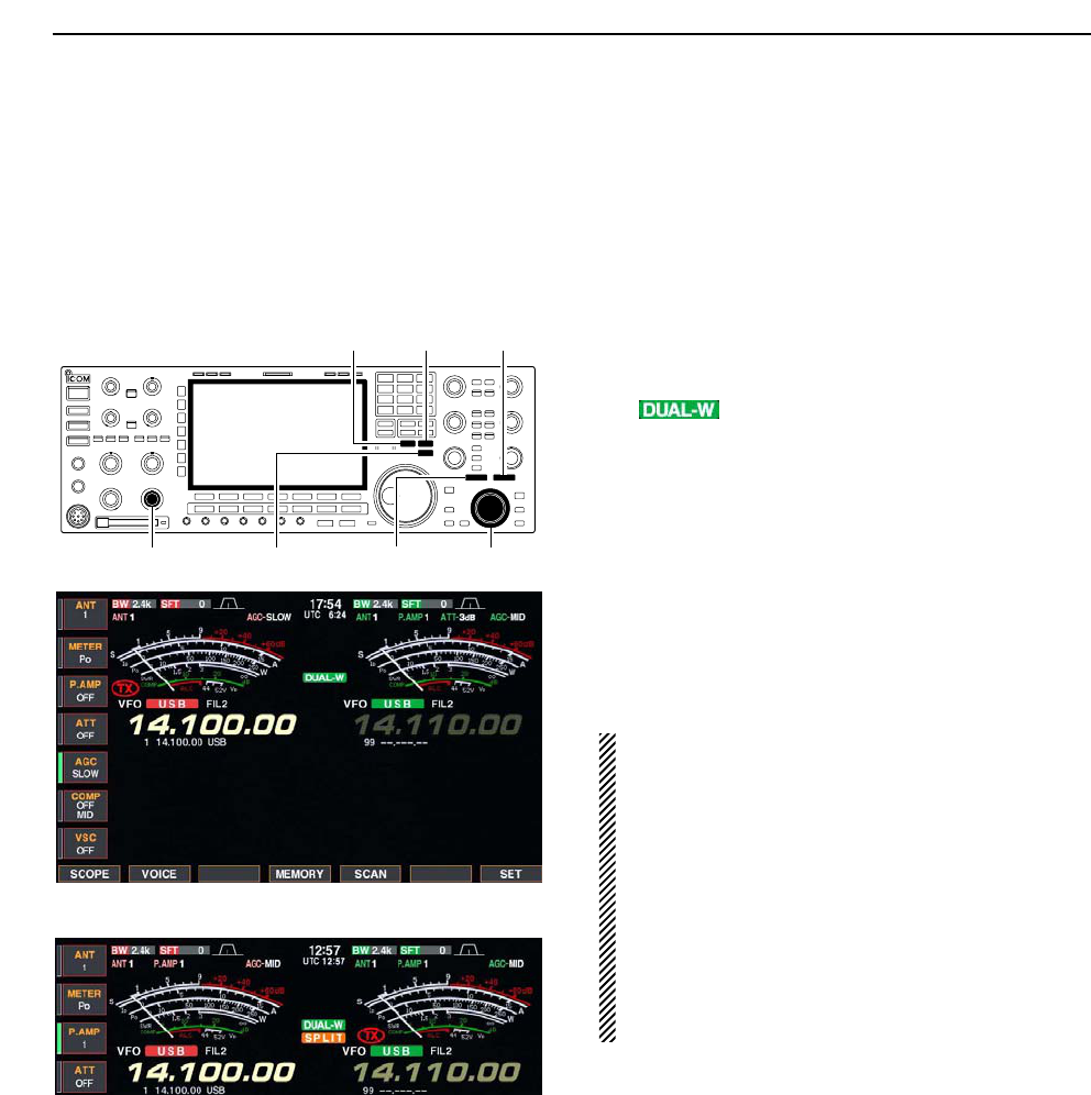
■Dualwatch operation
Dualwatch monitors 2 frequencies simultaneously.
The IC-7800 has 2 independent receiver circuits to
allow you to a dualwatch even in different frequency
band and mode.
qSet the desired frequency and mode into the main
band.
wPush [DUALWATCH].
• “ ” appears.
• Pushing [DUALWATCH] for 1 sec., the sub band is
equalized at the same time. This quick dualwatch func-
tion can be turned OFF in set mode. (p. 12-13)
eRotate the sub dial to set the desired frequency.
rPush [SUB] to enables the sub band access when
changing the frequency band, operating mode, etc.
in sub band.
• Push [MAIN] for the main band access.
tRotate [AF] for sub band to adjust the sub band
audio level.
yTo transmit on the sub band readout, push
[CHANGE] or [SPLIT].
NOTE:
•Beat may be sound according to the set frequen-
cy combination, such as 3.5 MHz and 7 MHz
band’s frequencies.
• Receiver sensitivity will be decreased when the
same frequency band and the same antenna are
selected during dualwatch.
• The RIT function can be used for the main read-
out only.
• The ∂TX function can be used for the transmit
readout (main readout when the split function
OFF; sub readout when the split function ON).
[MAIN]
[DUALWATCH][CHANGE] Sub dial[AF] for sub
[SPLIT][SUB]
5FUNCTIONS FOR RECEIVE
• Split frequency operation during dualwatch
5-17
■Noise blanker
The noise blanker eliminates pulse-type noise such as
from car ignitions. The noise blanker is not available
for FM mode.
qPush [NB] to turn the noise blanker function ON and
OFF.
• [NB] indicator above their switch lights green.
wRotate [NB] control to adjust the noise blanker
threshold level.
When using the noise blanker, received signals may
be distorted if they are excessively strong or the
noise type is different. Turn the noise blanker OFF,
or rotate [NB] control to a shallow position in such
case.
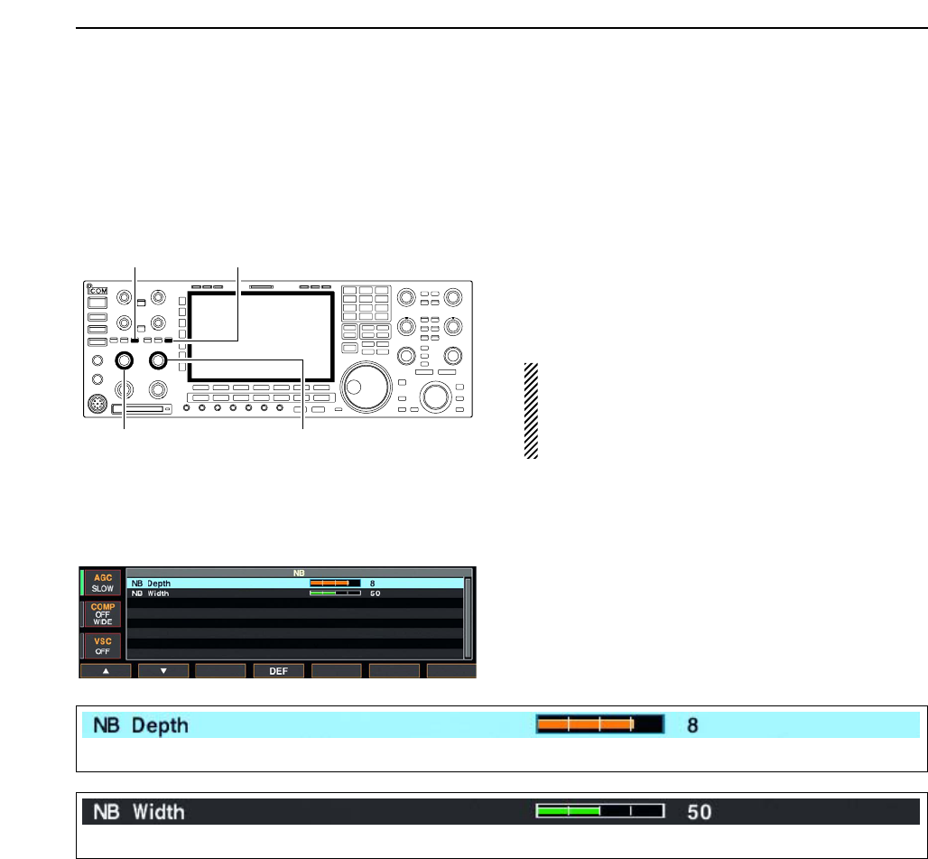
DNB set mode
To deal with various type of noises, attenuation level
and noise width can be set in NB set mode.
qPush [NB] for 1 sec. to enter NB set mode.
wPush [F-1•Y] or [F-2•Z] to select the desired item.
eRotate the main dial to set the desired level or value.
• Push [F-4•DEF] for 1 sec. to select a default value.
rPush [EXIT/SET] to exit filter shape set mode.
[NB] for main
[NB] control for sub[NB] control for main
[NB] for sub
5
FUNCTIONS FOR RECEIVE
Set the noise attenuation level within 1 to 10.
Set the noise pulse width within 1 to 100.
5-18
■Noise reduction
The noise reduction function reduces noise compo-
nents and picks out desired signals which are buried
in noise. The received signals are converted to digital
signals and then the desired signals are separated
from the noise.
qPush the [NR] to turn the noise reduction ON.
• [NR] indicator above their switch lights green.
wRotate the [NR] control to adjust the noise reduction
level.
ePush the [NR] switch to turn the noise reduction
OFF.
• [NR] indicator lights off.
Deep rotation of the [NR] control results in audio
signal masking or distortion. Set the [NR] control for
maximum readability.
■Dial lock function
The dial lock function prevents changes by accidental
movement of the main dial. The lock function electron-
ically locks the dial.
➥Push [LOCK] to toggle the dial lock function ON and
OFF.
• The [LOCK] indicator lights when the dial lock function
is in use.
[LOCK] indicator for main
[LOCK] for sub[LOCK] for main
[LOCK] indicator for sub
[NR] for main
[NR] control for sub[NR] control for main
[NR] for sub
5FUNCTIONS FOR RECEIVE
5-19
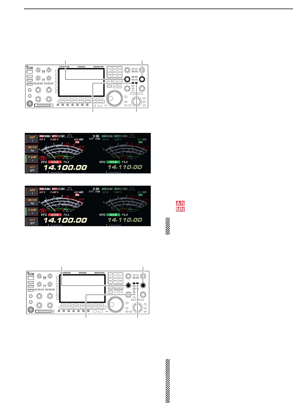
■Notch function
This transceiver has auto and manual notch functions.
The auto notch function automatically attenuates more
than 3 beat tones, tuning signals, etc., even if they are
moving. The manual notch can be set to attenuate a
frequency via the [NOTCH] control.
The auto notch can be used in SSB, AM and FM
modes.
The manual notch can be used in SSB, CW, RTTY,
PSK and AM modes.
• Auto notch indication
➥Push [NOTCH] to toggle the notch function between
auto, manual and OFF in SSB and AM modes.
➥Push [NOTCH] to turn the manual notch function
ON and OFF in CW mode.
➥Push [NOTCH] to turn the auto notch function ON
and OFF in FM mode.
• [NOTCH] indicator above their switch lights green.
• Push [NOTCH] for 1 sec. to select the notch filter width
for manual notch from wide, middle and narrow.
• Set to attenuate a frequency for manual notch via the
[NOTCH] control.
• “ ” appears when auto notch is in use.
• “ ” appears when manual notch is in use.
While operating the manual notch, noise may be
heard. This comes from the DSP unit and does not
indicate an equipment malfunction.
■Digital selector
The digital selector manually adjusts the center fre-
quency of the automatic pre-selector.
The automatic pre-selector filters the desired signal
only and eliminates intermodulation from another
bands strong signals at the RF stage.
The automatic pre-selector that operates in conjunc-
tion with the operating frequency, follows the change
in operating frequency at the minimum kHz steps.
qPush [DIGI-SEL] to turn the digital selector ON and
OFF.
• [DIGI-SEL] indicator above their switch lights green.
wRotate [DIGI-SEL] control to adjust the center fre-
quency.
NOTE:
• When rotating the main dial (and sub dial during the
dualwatch or split function) while the digital selector
is activated, mechanical noise will be heard due to
the switching noise from internal relays.
• The preamp (P.AMP1 or P.AMP2) cannot be used
while the digital selector is activated.
[DIGI-SEL] control for main
[DIGI-SEL] for sub[DIGI-SEL] for main
[DIGI-SEL] control for sub
[NOTCH] control for main
[NOTCH] for sub[NOTCH] for main
[NOTCH] control for sub
5
FUNCTIONS FOR RECEIVE
• Manual notch indication

6-1
FUNCTIONS FOR TRANSMIT Section 6
■VOX function …………………………………………………………… 6-2
DUsing the VOX function …………………………………………… 6-2
DAdjusting the VOX function ………………………………………… 6-2
DVOX set mode ……………………………………………………… 6-2
■Break-in function ………………………………………………………… 6-3
DSemi break-in operation …………………………………………… 6-3
DFull break-in operation ……………………………………………… 6-3
■∂TX function …………………………………………………………… 6-4
D∂TX monitor function ………………………………………………… 6-4
■Monitor function ………………………………………………………… 6-4
■Transmit filter width setting (SSB only) ……………………………… 6-5
■Speech compressor (SSB only) ……………………………………… 6-5
■Split frequency operation ……………………………………………… 6-6
■Quick split function ……………………………………………………… 6-7
DSplit lock function …………………………………………………… 6-7
6-2
■VOX function
The VOX (Voice-Operated Transmission) function
switches between transmit and receive with your voice.
This function provides an opportunity to input log en-
tries into your computer, etc., while operating.
DUsing the VOX function
qSelect a phone mode (SSB, AM, FM).
wPush [VOX/BK-IN] to turn the VOX function ON or
OFF.
• “VOX” appears while the VOX is in use.
• [VOX/BK-IN] indicator above this switch lights green.
DAdjusting the VOX function
qSelect a phone mode (SSB, AM, FM).
wPush [VOX/BK-IN] to turn VOX function ON.
eWhile speaking into the microphone with your nor-
mal voice level, rotate [VOX GAIN] to the point
where the transceiver is continuously transmitting.
rDuring receive, rotate [ANTI VOX] to the point
where the transceiver does not switching to transmit
with the receive audio from the speaker.
tAdjust the VOX delay and the VOX voice delay in
VOX set mode, if necessary.
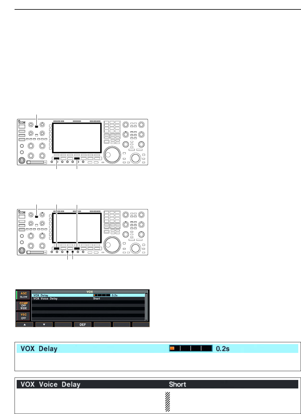
DVOX set mode
qPush [VOX/BK-IN] for 1 sec. to enter VOX set
mode.
wSelect the VOX gain item using [F-1•Y] or [F-2•Z].
eRotate the main dial to the desired set value or con-
dition.
• Push [F-4•DEF] for 1 sec. to select a default value.
rPush [EXIT/SET] to exit VOX set mode.
[VOX/BK-IN]
[ANTI VOX][VOX GAIN]
[AM/FM][SSB]
[VOX/BK-IN]
[AM/FM][SSB]
6FUNCTIONS FOR TRANSMIT
Set the VOX delay for a convenient interval before re-
turning to receive within 0 to 2.0 sec. range.
Set the VOX voice delay to prevent mis-transmission
of your voice when switching to transmit.
Short, Mid., Long and OFF settings are available.
When using the VOX voice delay, turn the TX mon-
itor function OFF. The transmission audio will be
echoed.
6-3
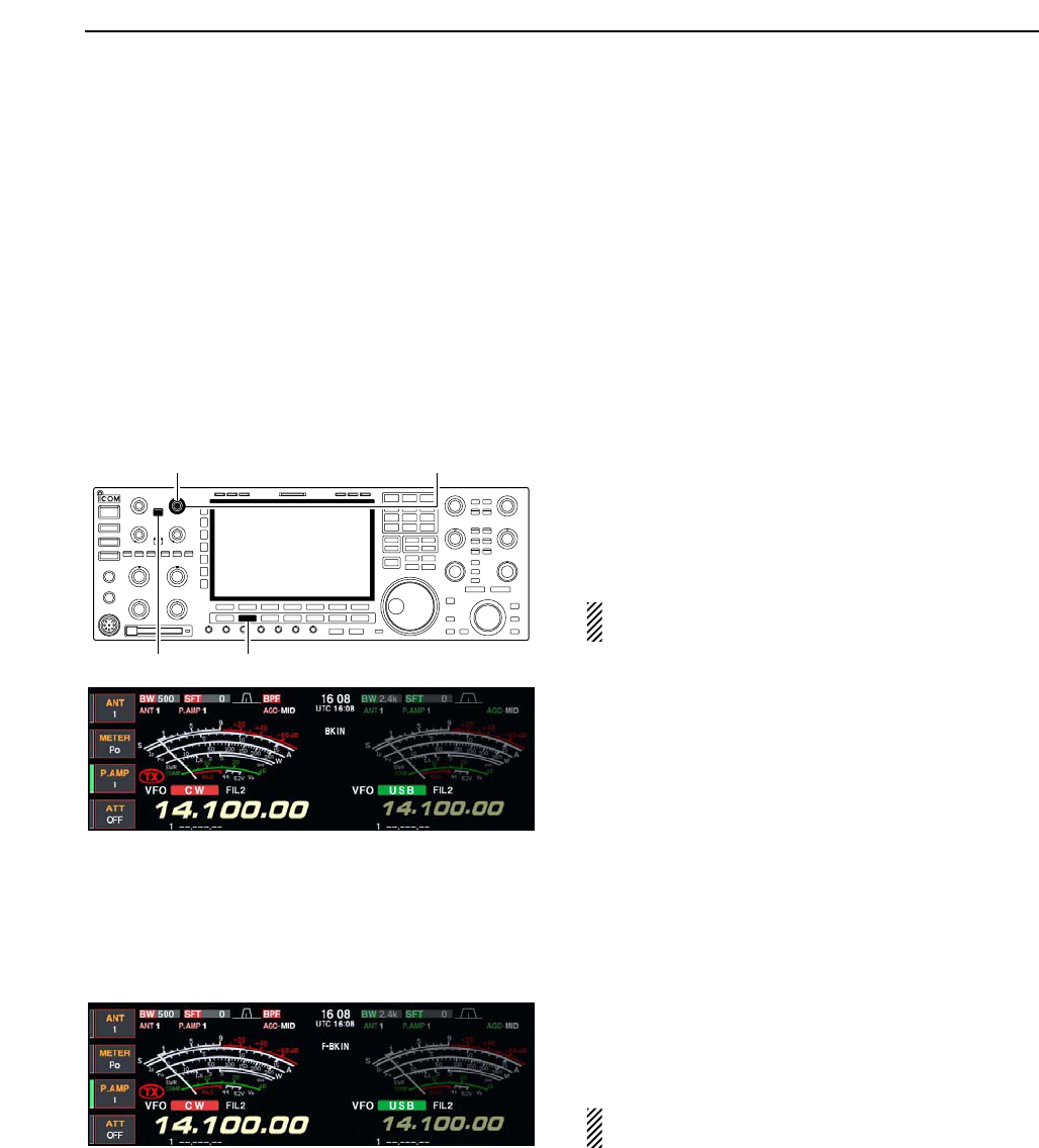
■Break-in function
The break-in function is used in CW mode to automat-
ically toggle the transceiver between transmit and re-
ceive when keying. The IC-7800 is capable for full
break-in or semi break-in.
DSemi break-in operation
During semi break-in operation, the transceiver selects
transmit when keying, then automatically returns to re-
ceive after a pre-set time from when you stop keying.
qPush [CW] to select CW or CW-R mode.
wPush [VOX/BK-IN] several times to turn the semi
break-in function ON.
• “BK IN” appears.
eRotate [DELAY] to set the break-in delay time (the
delay from transmit to receive).
When using a paddle, rotate [KEY SPEED] to adjust
the keying speed.
DFull break-in operation
During full break-in operation, the transceiver auto-
matically selects transmit while keying and returns to
receive immediately after keying is finished.
qPush [CW] to select CW or CW-R mode.
wPush [VOX/BK-IN] several times to turn the full
break-in function ON.
• “F-BK IN” appears.
When using a paddle, rotate [KEY SPEED] to adjust
the keying speed.
[KEY SPEED] (inner control) [DELAY] (outer control)
[VOX/BK-IN] [CW]
6
FUNCTIONS FOR TRANSMIT
6-4
■∂TX function
The ∂TX function shifts the transmit frequency up to
±9.999 kHz in 1 Hz steps (10 Hz steps when cancelling
the 1 Hz step readout) without moving the receive fre-
quency.
• See (3 on p. 1-11 for function description.
qPush [∂TX].
• “ ” appears.
wRotate [RIT/∂TX].
eTo reset the ∂TX frequency, push [CLEAR] for
1 sec.
• Push [CLEAR] momentarily to reset the RIT frequency
when the quick RIT/∂TX clear function is ON. (p. 12-1)
rTo cancel the ∂TX function, push [∂TX] again.
• “ ” disappears.
D∂TX monitor function
When the ∂TX function is ON, pushing and holding
[XFC] allows you to monitor the operating frequency
directly (∂TX is temporarily cancelled).
✔For your convenience— Calculate function
The shift frequency of the ∂TX function can be
added/subtracted to the displayed frequency.
➥While displaying the ∂TX shift frequency, push
[∂TX] for 1 sec.
■Monitor function
The monitor function allows you to monitor your trans-
mit IF signals in any mode through the speaker. Use
this to check voice characteristics while adjusting SSB
transmit tones. (p. 12-4) The CW sidetone functions re-
gardless of the [MONI] switch setting.
qPush [MONI] to switch the monitor function ON and
OFF.
• [MONI] indicator above this switch lights green.
wRotate [MONI GAIN] for the clearest audio output
while pushing [PTT] and speaking into the micro-
phone.
NOTE: When using the VOX voice delay, turn the
monitor function OFF. The transmission audio will
be echoed.
[MONI GAIN][MONI]
[XFC]
[RIT/∂TX] [∂TX]
[CLEAR]
6FUNCTIONS FOR TRANSMIT
6-5
■Transmit filter width setting (SSB only)
The transmit filter width for SSB mode can be selected
from wide, middle and narrow.
➥During USB or LSB mode selection, push [COMP]
for 1 sec. several times to select the desired trans-
mit filter width from wide, middle and narrow.
• The filter functions regardless of the speech compressor
use.
• The following filters are specified as the default. Each of
the filter width can be re-set in level set mode. (p. 12-5)
WIDE : 100 Hz to 2.9 kHz
MID : 300 Hz to 2.7 kHz
NAR : 500 Hz to 2.5 kHz
■Speech compressor (SSB only)
The speech compressor increases average RF output
power, improving signal strength and readability in
SSB mode only.
qSelect USB or LSB mode and adjust [MIC] to a suit-
able level.
• Push [METER] several times to select the ALC meter for
microphone gain adjustment.
wPush [COMP] to turn the speech compressor ON.
ePush [METER] once to select the COMP meter.
rWhile speaking into the microphone, rotate [COMP]
control, so that the COMP meter reads within the
COMP zone (10 to 20 dB range) with your normal
voice level.
When the COMP meter peaks exceed the COMP
zone, your transmitted voice may be distorted.
tPush [METER] 5 times to select the ALC meter.
yWhile speaking into the microphone, rotate [DRIVE],
so that the ALC meter reads within the 30 to 50%
range of the ALC zone with your normal voice level.
✔For your convenience
Push [METER] for 1 sec. to display the multi-function
meter that can check the ALC and COMP level at a
glance.
S
ID
0
510
15
0
010
44
ALC 52V
VD
20
dB
11.5 23∞
10 50 100 150 200 250
PO
SWR
COMP
A
W
1
59+20 +40 +60dB
COMP zone
[COMP] control [DRIVE]
[COMP][MIC] [METER]
[COMP]
6
FUNCTIONS FOR TRANSMIT
6-6
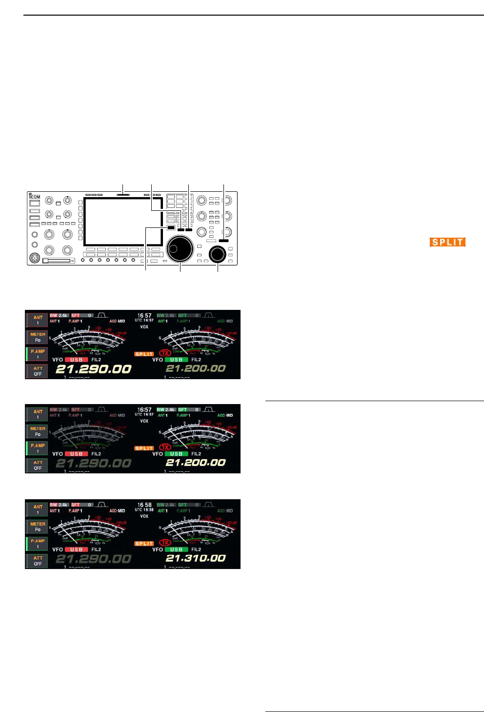
■Split frequency operation
Split frequency operation allows you to transmit and
receive in the same mode on two different frequencies.
The split frequency operation is basically performed
using 2 frequencies on the main and sub readouts.
The following is an example of setting 21.290 MHz for
receiving and 21.310 MHz for transmitting.
qSet 21.290 MHz (USB) in VFO mode.
wPush [SPLIT] momentarily, then push [M=S] for
1 sec.
• The quick split function is much more convenient for se-
lecting the transmit frequency. See the next section for
details.
• The equalized transmit frequency and “ ” ap-
pear on the LCD.
• [SPLIT] indicator lights.
• “TX” appears to show the transmit frequency readout.
eSet the transmit frequency to 21.310 MHz with the
one of following ways.
• When the split function ON ➥Rotate the main dial while pushing [XFC].
➥Rotate the sub dial.
• The transmit frequency can be monitored while push-
ing [XFC] or using dualwatch.
rNow you can receive on 21.290 MHz and transmit
on 21.310 MHz.
To change the transmit and receive frequencies, push
[CHANGE] to exchange the main and sub readouts.
• When [XFC] is pushed
✔
CONVENIENT
• Direct shift frequency input
The shift frequency can be entered directly.
qPush [F-INP•ENT].
wEnter the desired shift frequency with the digit keys.
• 1 kHz to 1 MHz can be set.
• When you require a minus shift direction, push [GENE•.]
in advance.
• The split frequency operation is ready ePush [SPLIT].
• The shift frequency is input in the sub readout and the
split function is turned ON.
[Example]
To transmit on 1 kHz higher frequency:
- Push [F-INP•ENT], [1.8•1] then [SPLIT].
To transmit on 3 kHz lower frequency:
- Push [F-INP•ENT], [GENE•.], [7•3] then [SPLIT].
• Split lock function
Accidentally releasing [XFC] while rotating the main
dial changes the receive frequency. To prevent this,
use both the split lock and dial lock functions to change
the transmit frequency only. The split lock function can-
cels the dial lock function while pushing [XFC] during
split frequency operation.
The dial lock’s effectiveness during split frequency op-
eration can be selected in the set mode for both re-
ceive and transmit frequencies; or only the receive fre-
quency. (p. 12-14)
Sub dialMain dial
[SPLIT][CHANGE]
[XFC]
[M=S]
[SPLIT] indicator
6FUNCTIONS FOR TRANSMIT
6-7
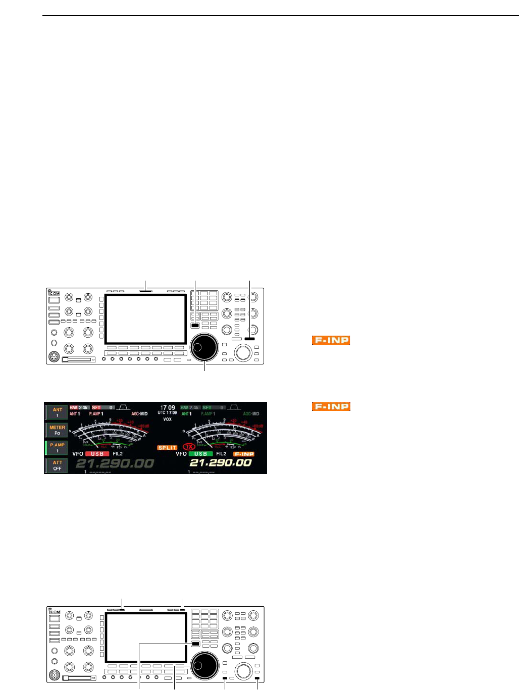
■Quick split function
When you find a DX station, an important considera-
tion is how to set the split frequency.
When you push the [SPLIT] switch for 1 sec., split fre-
quency operation is turned ON, the sub readout is
equalized to the main readout frequency and enters
standby for transmit frequency input.
This shortens the time needed to start split frequency
operation.
The quick split function is ON by default. For your con-
venience, it can be turned OFF in set mode. (p. 12-14)
In this case, the [SPLIT] switch does not equalize the
main and sub readout frequencies.
qSuppose you are operating at 21.290 MHz (USB) in
VFO mode.
wPush [SPLIT] for 1 sec.
• Split frequency operation is turned ON.
• The sub readout is equalized to the main readout fre-
quency.
• “ ” indicator appears and the sub readout en-
ters standby for transmit frequency input.
eEnter the desired offset frequency from the keypad
then push [SPLIT], or set the transmit frequency with
the main dial while pushing [XFC], or with the sub
dial.
• “ ” indicator disappears when [XFC] is pushed
or the main/sub dial is rotated.
• Offset frequency setting with the keypad— example
To transmit on 1 kHz higher frequency:
- Push [F-INP•ENT], [1.8•1] then [SPLIT].
To transmit on 3 kHz lower frequency:
- Push [F-INP•ENT], [GENE•.], [7•3] then [SPLIT].
DSplit lock function
The split lock function is convenient for changing only
the transmit frequency. When the split lock function is
not used, accidentally releasing [XFC] while rotating the
main dial, changes the receive frequency. The split lock
function is ON by default, but can be turned OFF in set
mode. (p. 12-14)
qWhile split frequency operation is ON, push [LOCK]
for both main and sub band to activate the split lock
function.
wWhile pushing [XFC], rotate the main dial to change
the transmit frequency.
• If you accidentally release [XFC] while rotating the main
dial, the receive frequency does NOT change.
Main dial[XFC] [LOCK]
for main
[LOCK]
for sub
[LOCK] indicator for main [LOCK] indicator for sub
Main dial
[SPLIT][XFC]
[SPLIT] indicator
6
FUNCTIONS FOR TRANSMIT

7-1
VOICE RECORDER FUNCTIONS Section 7
■About digital voice recorder …………………………………………… 7-2
■Recording a received audio …………………………………………… 7-3
DBasic recording ……………………………………………………… 7-3
DOne-touch recording ………………………………………………… 7-3
■Playing the recorded audio …………………………………………… 7-4
DBasic playing ………………………………………………………… 7-4
DOne-touch playing …………………………………………………… 7-4
■Protect the recorded contents ………………………………………… 7-5
■Erasing the recorded contents ………………………………………… 7-5
■Recording a message for transmit …………………………………… 7-6
DRecording …………………………………………………………… 7-6
DConfirming a message for transmit ………………………………… 7-6
■Programming a memory name ……………………………………… 7-7
■Sending a recorded message ………………………………………… 7-8
DTransmit level setting ……………………………………………… 7-8
■Voice set mode ………………………………………………………… 7-9
■Saving a voice memory into the CF card …………………………… 7-10
DSaving the received audio memory ……………………………… 7-10
DSaving the TX memory …………………………………………… 7-10
7-2
■About digital voice recorder
The IC-7800 has digital voice memories, up to 4 chan-
nels for transmit, and up to 20 channels for receive.
A maximum message length of 30 sec. can be
recorded into a receive channel and the total message
length of up to 209 sec., and a total message length of
up to 99 sec. can be recorded in transmit channels.
Providing a transmission memory is very convenient
for repeated CQ and number transmissions at contest
times, as well as when making consecutive calls in
DX’pedition.
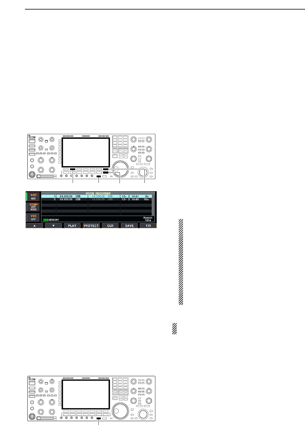
qSelect any mode.
wPush [F-2•VOICE] to display voice recorder screen.
ePush [EXIT/SET] to display voice recorder menu.
rPush [F-1•PLAY] or [F-2•MIC REC] to select the de-
sired memory channel screen, then records audio or
playback the contents as described below.
tPush [EXIT/SET] twice to exit voice recorder screen.
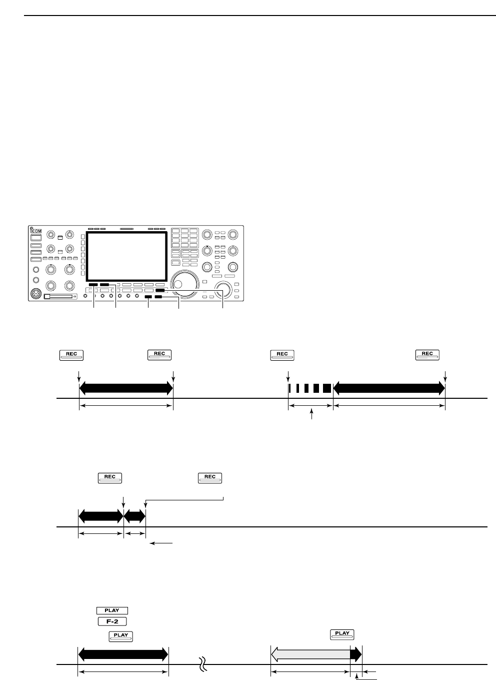
• Example— When [REC] is pushed for 1sec.
• Example— When [REC] is pushed momentarily
• Playing back the all contents in a channel • Playing back the end of 5 sec.* in a channel
Push for 1 sec.
(starts recording)
Push for 1 sec.
(starts recording)
Or, push for 1 sec.
Push momentarily
(stops recording)
Push momentarily
(starts recording)
Push momentarily
(starts recording)
Push momentarily.
Push momentarily.
Push momentarily
(stops recording)
20 sec.
15 sec.
(default)
30 sec. (max.) Not playing back Play back (5 sec.; default)
3 sec.
30 sec.
Push [REC] momentarily within 30 sec.
after pushing [REC] for 1 sec., records
the all contents.
Push [REC] momentarily
records the contents of
the previous 15 sec.*
When [REC] is pushed momentarily again within 15 sec.*
from the last [REC] operation, all the contents between
[REC] operations will be recorded.
Push [REC] momentarily after passing
30 sec. from pushing [REC] for 1 sec.,
records the 30 sec. before canceling
the record.
These contents
won’t be recorded.
*The recording time period can be changed with “Normal Rec Time” in voice set mode (p. 7-9).
*The playing back time period can be changed with
“Short Play Time” in voice set mode (p. 7-9).
NOTE: The contents will be recorded into an independent memory
channels automatically.
[EXIT/SET][REC] [PLAY][F-2][F-1]
7VOICE RECORDER FUNCTIONS
7-3
■Recording a received audio
Up to 20 channels of receive voice memories are
available in the IC-7800. And the total audio length of
up to 209 sec. can be recorded in receive channels.
However, the maximum recordable length into a
channel is 30 sec.
This voice recorder records not only the received
audio, but also the information that the set operating
frequency, mode, and the recording time for your fu-
ture reference as the memory names.
DBasic recording
qPush [EXIT/SET] several times to close a multi-func-
tion screen, if necessary.
wSelect the desired mode.
ePush [F-2•VOICE] to call up the voice recorder
screen.
• Previously selected screen, TX or RX memory, is dis-
played. If the TX memory channel (T1–T4) appears,
push [F-7•T/R] to select RX memory channel.
rPush [REC] for 1 sec. to start recording.
• The recording timer counts down.
• The operating frequency, mode and current time are pro-
grammed as the memory names automatically.
tPush [REC] momentarily to stop recording.
IMPORTANT!
Push [REC] to stop recording before, or when
30 sec. has passed from the start of recording.
The voice recorder memory records the 30 sec.
(max.) of audio before [REC] is pushed.
For example, when recording 40 sec. of audio,
the first 10 sec. audio will be over-recorded with
the last 10 sec., so that the total of audio recorded
is 30 sec. only.
When you records a 21st audio, or when the total
audio length exceeds 209 sec., the oldest
recorded audio is automatically erased to make
room for the new audio.
yPush [EXIT/SET] twice to exit the voice recorder
screen.
NOTE: When transmit (or [PTT] is pushed) while
recording, no audio will be recorded.
DOne-touch recording
To record the receiving signal contents immediately,
one-touch voice recording is available.
➥Push [REC] momentarily to records the previous
15 sec. audio.
• The recordable time period can be set in voice set mode.
(p. 7-9)
[REC]
[EXIT/SET] [F-7•T/R][REC][F-2•VOICE]
7
VOICE RECORDER FUNCTIONS
7-4
■Playing the recorded audio
DBasic playing
qPush [EXIT/SET] several times to close a multi-func-
tion screen, if necessary.
wPush [F-2•VOICE] to call up the voice recorder
screen.
• Previously selected screen, TX or RX memory, is dis-
played. If the TX memory channel (T1–T4) appears,
push [F-7•T/R] to select RX memory channel.
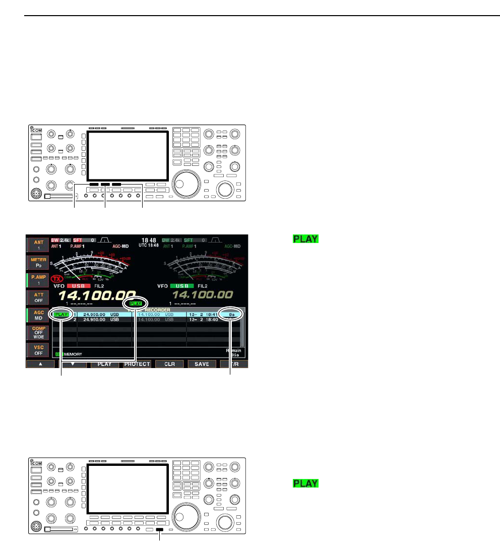
ePush [F-1•Y] or [F-2•Z] to select the desired voice
memory to playback.
rPush [F-3•PLAY] to start playback.
• “ ” indicators appear and the timer counts down.
tPush [F-3•PLAY] again to stop playback if desired.
• Playback is terminated automatically when all of the
recorded contents in the channel are played, or after
30 sec.
yPush [EXIT/SET] twice to exit the voice recorder
screen.
DOne-touch playing
The previously recorded audio in channel 1 can be
playback without selecting voice recorder screen.
➥Push [PLAY] momentarily to playback the end 5 sec.
of the previously recorded audio.
• “ ” indicator appears.
• Playback is terminated automatically when all of the
recorded contents in the channel are played, or after
5 sec.
• The playback time period can be set in voice set mode.
(p. 7-9)
[PLAY]
Appear Counts down
[F-1•Y] [F-2•Z] [F-3•PLAY]
7VOICE RECORDER FUNCTIONS
7-5
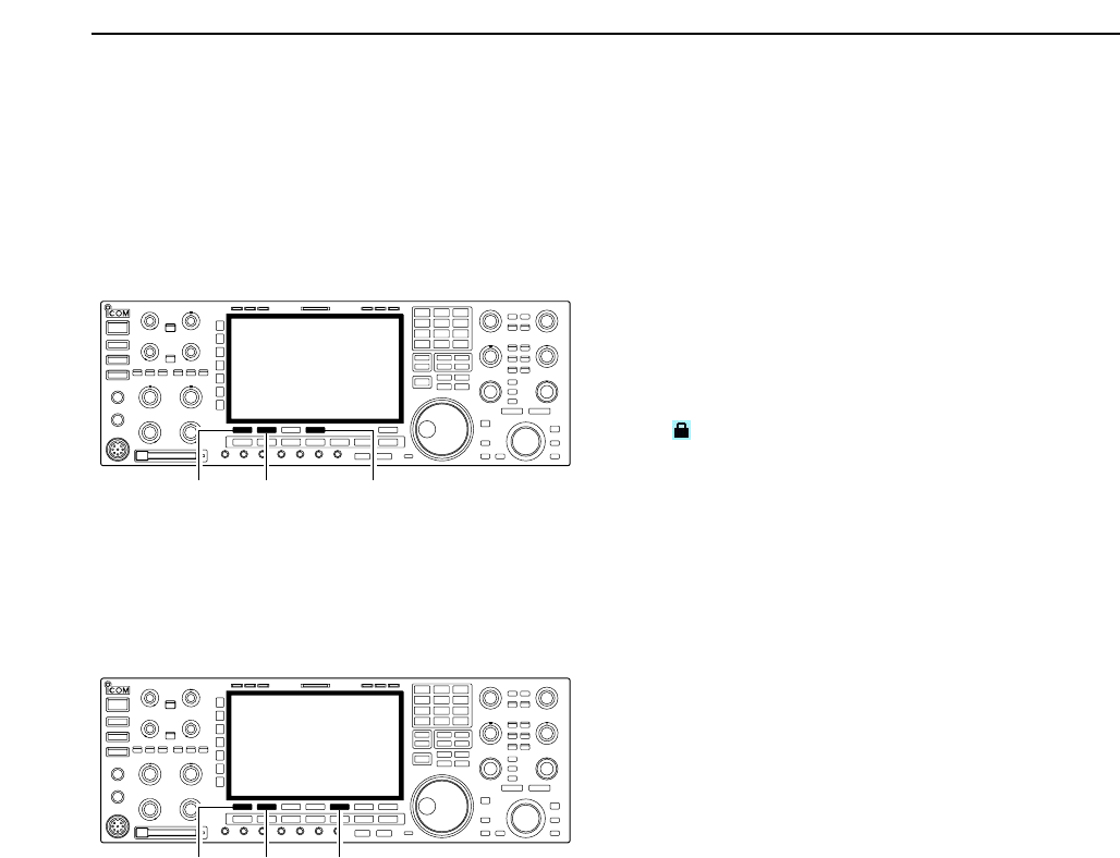
■Protect the recorded contents
The protect function is available to protect the recorded
contents from accidental erasing, such as over-record,
etc.
qCall up the voice recorder screen, RX memory.
wPush [F-1•Y] or [F-2•Z] to select the desired voice
memory.
ePush [F-4•PROTECT] to turn the protect function
ON and OFF.
• “ ” indicator appears when the contents is protected.
rPush [EXIT/SET] twice to exit the voice recorder
screen.
■Erasing the recorded contents
The recorded contents can be erased channel
independently.
qCall up the voice recorder screen, RX memory.
wPush [F-1•Y] or [F-2•Z] to select the desired voice
memory to be erased.
ePush [F-5•CLR] for 1 sec. to erase the contents.
• Push [F-4•PROTECT] to release the protection in ad-
vance if necessary.
rPush [EXIT/SET] twice to exit the voice recorder
screen.
[F-1•Y][F-2•Z][F-5•CLR]
[F-1•Y][F-2•Z] [F-4•PROTECT]
7
VOICE RECORDER FUNCTIONS
7-6
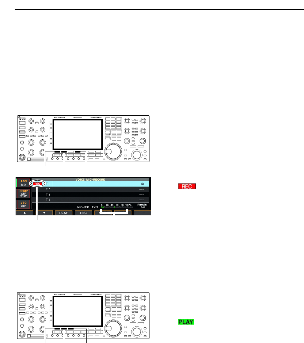
■Recording a message for transmit
To transmit a message using a voice recorder, record
the desired message in advance as described below.
The IC-7800 has digital voice memories for transmis-
sion, up to 4 channels and the total message length of
up to 99 sec. can be recorded.
DRecording
qPush [EXIT/SET] several times to close a multi-func-
tion screen, if necessary.
wPush [F-2•VOICE] to call up the voice recorder
screen.
ePush [EXIT/SET] to select voice recorder menu.
rPush [F-2•MIC REC] to select the voice mic. record
screen.
tPush [F-1•Y] or [F-2•Z] to select the desired mem-
ory channel.
yPush [F-4•REC] for 1 sec. to start recording.
• “ ” indicator appears.
• Speak into the microphone without pushing [PTT].
• Previously recorded contents are cleared.
• Audio output from the internal speaker is automatically
muted.
uWhile speaking into the microphone with your nor-
mal voice level, adjust the [MIC] control so that the
[MIC-REC LEVEL] indicator reads within 100%.
iPush [F-4•REC] momentarily to stop recording.
• The recording is terminated automatically when the re-
maining time becomes 0 sec.
oPush [EXIT/SET] twice to exit the voice recorder
screen.
DConfirming a message for transmit
qPerform the steps qto ras “DRecording” above.
wPush [F-1•Y] or [F-2•Z] to select the desired mem-
ory channel.
ePush [F-3•PLAY] to playback the recorded contents.
• “ ” indicator appears.
rPush [F-3•PLAY] again to stop playback.
• Playback is terminated automatically when all of the
recorded contents in the channel are played.
tPush [EXIT/SET] twice to exit the voice recorder
screen.
[F-1•Y] [F-2•Z] [F-3•PLAY]
Appears Adjust [MIC] control so that this
indicator reads within 100%.
[F-1•Y] [F-2•Z] [F-4•REC]
7VOICE RECORDER FUNCTIONS
7-7
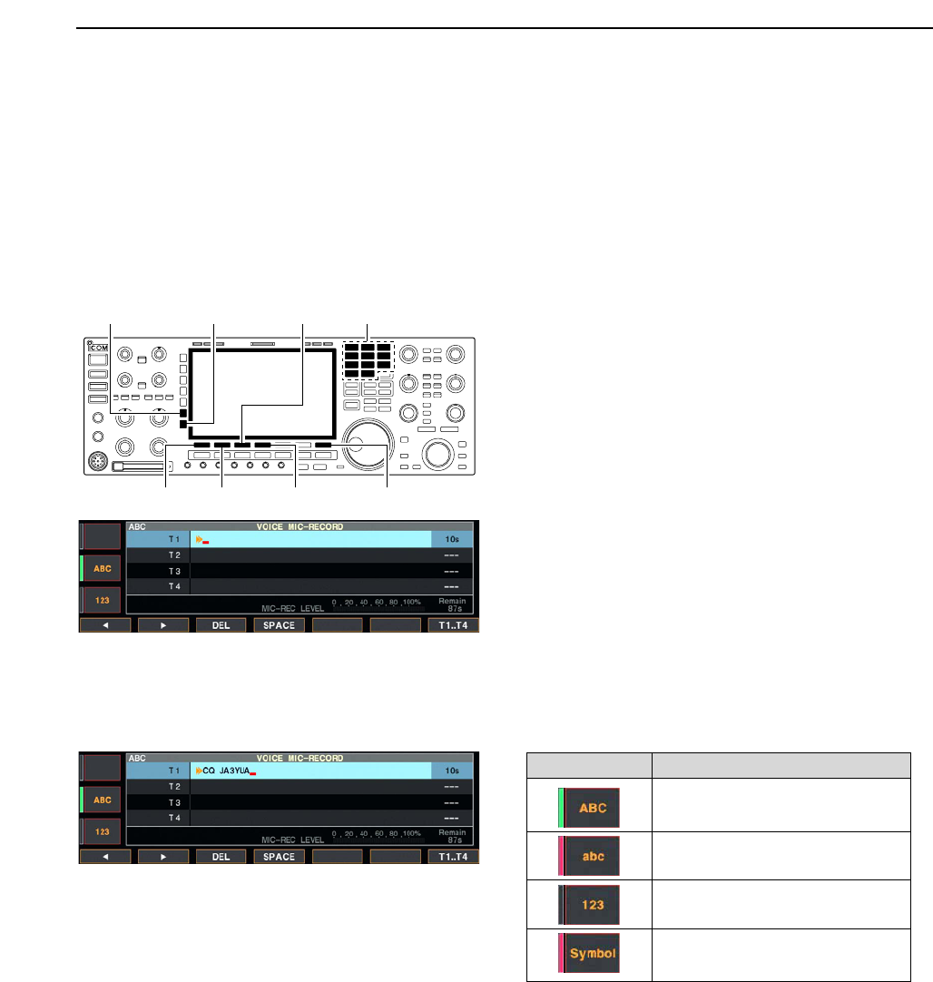
■Programming a memory name
Memory channels can be tagged with alphanumeric
names of up to 20 characters each.
Capital letters, small letters, numerals, some symbols
(! # $ % & ¥ ? “ ‘ ` ^ + – ✱/ . , : ; = < > ( ) [ ] { } | _ ~@)
and spaces can be used. (See the table below.)
qRecord a message as described in page 7-6.
wDuring the voice mic. record screen indication, push
[F-5•NAME] to enter memory name edit condition.
• A cursor appears and blinks.
ePush [F-7•T1..T4] several times to select the desired
voice memory.
rInput the desired character by rotating the main dial
or by pushing the band key for number input.
• Push [ABC] or [abc] to toggle capital and small letters.
• Push [123] or [Symbol] to toggle numerals and symbols.
• Push [F-1•Ω] or [F-2•≈] for cursor movement.
• Push [F-3•DEL] to delete the selected character.
• Push [F-4•SPACE] to input a space.
• Pushing the transceiver’s keypad, [0]–[9], can also enter
numerals.
tPush [EXIT/SET] to input and set the name.
• The cursor disappears.
yRepeat steps eto tto program another voice
memory’s name, if desired.
uPush [EXIT/SET] twice to exit the voice recorder
screen.
• Voice memory name editing example • Usable characters
[F-1•Ω] [F-2•≈] [F-4•SPACE] [F-7•T1..T4]
[F-3•DEL] Keypad[ABC]/[abc] [123]/[Symbol]
7
VOICE RECORDER FUNCTIONS
Key selection Editable characters
A to Z (capital letters)
a to z (small letters)
0 to 9 (numbers)
! # $ % & ¥ ? “ ‘ ` ^ + – ✱/ . , : ; =
< > ( ) [ ] { } | _ ~@
7-8
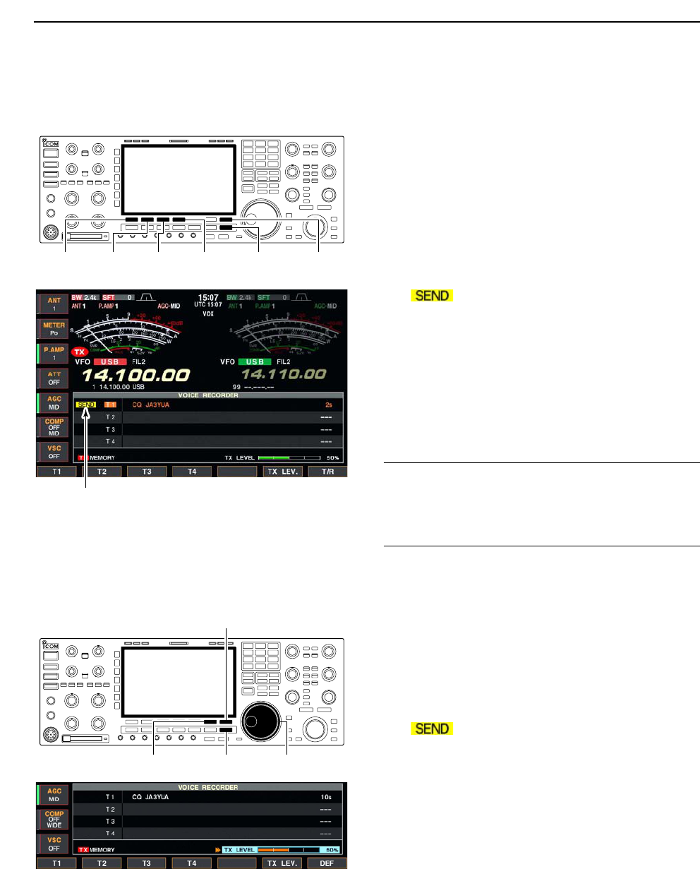
■Sending a recorded message
qPush [EXIT/SET] several times to close a multi-func-
tion screen, if necessary.
wSelect a phone mode by pushing [SSB] or [AM/FM].
ePush [F-2•VOICE] to call up the voice recorder
screen.
• If the receive voice memory channel appears, push
[F-7•T/R] to select TX memory channel (T1–T4).
rPush the desired memory channel switch, [F-1•T1]
to [F-4•T4], momentarily to transmit the contents.
• The transceiver transmits automatically.
• “ ” indicator appears and the memory timer
counts down.
• The transmitting contents are sound from the speaker as
the default. This can be turned OFF in voice set mode.
(p. 7-9)
tPush the selected memory channel switch, [F-1•T1]
to [F-4•T4], again to stop, if desired.
• The transceiver returns to receive automatically when all
of the recorded contents in the channel are transmitted.
yPush [EXIT/SET] twice to exit the voice memory
screen.
✔
For your information
When an external keypad is connected to [EXT KEY-
PAD], the recorded message, T1–T4, can be transmit-
ted without opening the voice recorder screen.
See page 2-6 for details.
DTransmit level setting
qCall up the voice recorder screen as described as
above.
wPush [F-6•TX LEV.] to select the voice memory
transmit level set condition.
ePush the desired memory channel switch, [F-1•T1]
to [F-4•T4], momentarily to transmit the contents.
• The transceiver transmits automatically.
• “ ” indicator appears and the memory timer
counts down.
rRotate the main dial to adjust the transmit voice
level.
• Push [F-7•DEF] for 1 sec. to select the default condition.
tPush [EXIT/SET] to return to the voice recorder
screen.
[F-6•TX LEV.] [EXIT/SET] Main dial
[F-7•T/R]
Appears
[F-1•T1] [F-2•T2] [F-3•T3] [F-4•T4] [EXIT/SET] [F-7•T/R]
7VOICE RECORDER FUNCTIONS
7-9
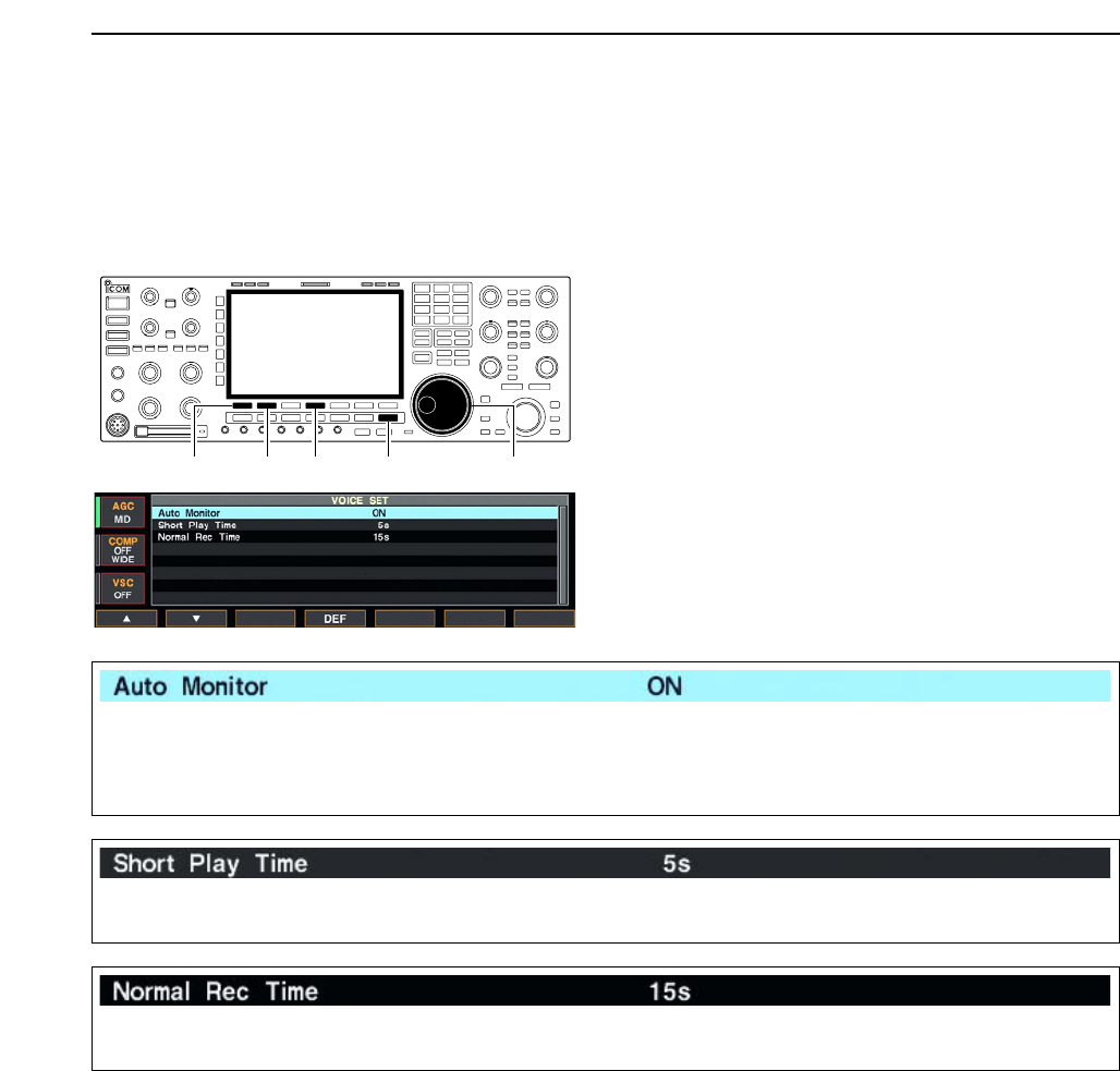
■Voice set mode
Sets the automatic monitor function, short play and
normal recording times for voice recorder.
qPush [EXIT/SET] several times to close a multi-func-
tion screen, if necessary.
wPush [F-2•VOICE] to call up the voice recorder
screen.
ePush [EXIT/SET] to select voice recorder menu.
rPush [F-7•SET] to select voice set mode screen.
tPush [F-1•Y] or [F-2•Z] to select the desired item.
yRotate main dial to set the desired condition or
value.
• Push [F-4•DEF] for 1 sec. to select the default condition
or value.
uPush [EXIT/SET] to exit the voice set mode screen.
[F-2•Z][F-1•Y][EXIT/SET] Main dial[F-4•DEF]
7
VOICE RECORDER FUNCTIONS
Turn the automatic monitor function for recorded
audio contents transmission.
• ON : Monitors transmitting audio automatically
when sending a recorded audio.
• OFF : Monitors transmitting audio only when the
monitor function is in use.
Set the desired time period for the one-touch playing
(when [PLAY] is pushed momentarily).
• 3 to 10 sec. in 1 sec. steps can be set.
(default: 5 sec.)
Set the desired time period for the for one-touch
recording (when [REC] is pushed momentarily).
• 5 to 15 sec. in 1 sec. steps can be set.
(default: 15 sec.)
7-10
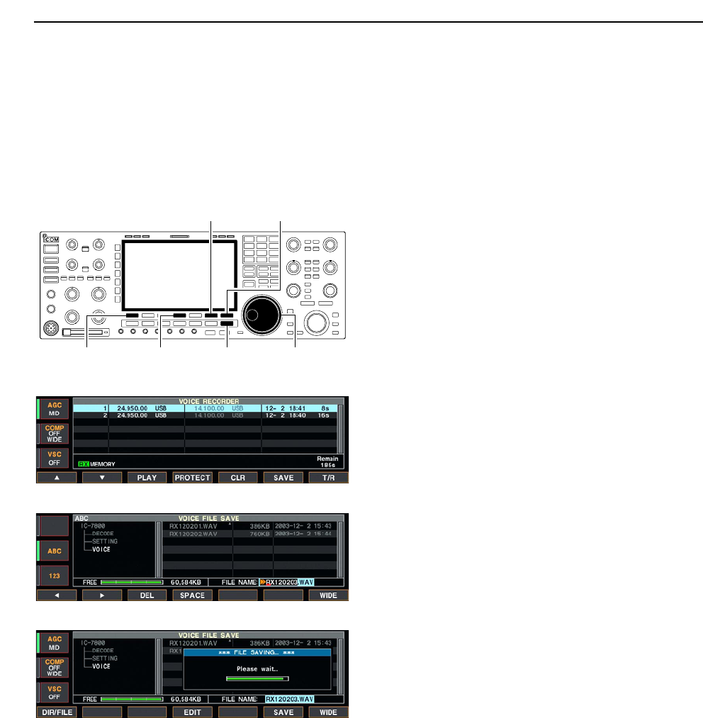
■Saving a voice memory into the CF memory card
DSaving the received audio memory
The recorded RX memory contents can be saved into
the CF (Compact Flash) memory card.
qDuring voice recorder RX memory screen indica-
tion, push [F-6•SAVE] to select voice file save
screen.
• Previously selected screen, TX or RX memory, is dis-
played. If the TX memory channel (T1–T4) appears,
push [F-7•T/R] to select RX memory channel.
wChange the following conditions if desired.
• File name:
zPush [F-4•EDIT] to select file name edit con-
dition.
• Push [F-1• DIR/FILE] several times to select the
file name, if necessary.
xPush [ABC], [123] or [Symbol] to select the
character group, then rotate the main dial to
select the character.
• [ABC] : A to Z (capital letters); [123]: 0 to 9 (nu-
merals); [Symbol]: ! # $ % & ‘ ` ^ + – = ( ) [ ] { } _ ~
@ can be selected.
• Push [F-1•Ω] to move the cursor left, push [F-2•≈]
to move the cursor right, push [F-3•DEL] to delete
a character and push [F-4•SPACE] to insert a
space.
cPush [EXIT/SET] to set the file name.
• Saving location
zPush [F-1•DIR/FILE] to select tree view
screen.
xSelect the desired directory or folder in the CF
memory card.
• Push [F-4•Ω≈] to select the upper directory.
• Push [F-2•Y] or [F-3•Z] to select folder in the
same directory.
• Push [F-4•Ω≈] for 1 sec. to select a folder in the
directory.
• Push [F-5•REN/DEL] to rename the folder.
• Push [F-5•REN/DEL] for 1 sec. to delete the
folder.
• Push [F-6•MAKE] for 1 sec. to making a new
folder. (Edit the name with the same manner as
the “• File name” above.)
cPush [F-1•DIR/FILE] twice to select the file
name.
ePush [F-6•SAVE].
• After the saving is completed, return to PSK decode
menu 2 automatically.
DSaving the TX memory
The TX memory contents can also be saved into the
CF (Compact Flash) memory card. However, the con-
tents are saved with the memory channel list, set mode
conditions, etc. at the same time.
See page 12-23 for details.
[F-1•DIR/FILE] Main dial[EXIT/SET][F-4•EDIT]
[F-6•SAVE] [F-7•WIDE]
7VOICE RECORDER FUNCTIONS
• Voice recorder RX memory screen
• Voice file save screen— file name edit
• While saving