ICOM orporated 259000 Amateur HF Scanning Transceiver User Manual IC 7800 Eng
ICOM Incorporated Amateur HF Scanning Transceiver IC 7800 Eng
Contents
- 1. Users Manual Part 1
- 2. Users Manual Part 2
- 3. Users Manual Part 3
- 4. Users Manual Part 4
- 5. Users Manual Part 5
Users Manual Part 2

4-1
RECEIVE AND TRANSMIT Section 4
■Operating SSB ………………………………………………………… 4-2
DConvenient functions for receive ……………………………………4-2
DConvenient functions for transmit ……………………………………4-3
DAbout 5 MHz band operation (USA version only) …………………4-3
■Operating CW …………………………………………………………… 4-4
DConvenient functions for receive ……………………………………4-4
DConvenient functions for transmit ……………………………………4-5
DAbout CW reverse mode ……………………………………………4-5
DAbout CW pitch control ………………………………………………4-5
DCW side tone function ………………………………………………4-5
DAPF (Audio Peak Filter) operation …………………………………4-6
DAbout 137 kHz band operation (Europe, UK, Italy, Spain, France
versions only) …………………………………………………………4-6
■Electronic keyer functions ……………………………………………… 4-7
DMemory keyer screen …………………………………………………4-8
DEditing a memory keyer ………………………………………………4-9
DContest number set mode …………………………………………4-10
DKeyer set mode ………………………………………………………4-11
■Operating RTTY (FSK) ……………………………………………… 4-13
DConvenient functions for receive …………………………………4-14
DAbout RTTY reverse mode …………………………………………4-14
DTwin peak filter ………………………………………………………4-14
DFunctions for the RTTY decoder indication ………………………4-15
DSetting the decoder threshold level ………………………………4-15
DRTTY memory transmission ………………………………………4-16
DAutomatic transmission/reception setting …………………………4-16
DEditing RTTY memory ………………………………………………4-17
DRTTY decode set mode ……………………………………………4-18
DData saving …………………………………………………………4-20
■Operating PSK ………………………………………………………… 4-21
DConvenient functions for receive …………………………………4-22
DAbout BPSK and QPSK mode ……………………………………4-22
DFunctions for the PSK decoder indication ………………………4-23
DSetting the decoder threshold level ………………………………4-23
DPSK memory transmission …………………………………………4-24
DAutomatic transmission/reception setting …………………………4-24
DEditing PSK memory ………………………………………………4-25
DPSK decode set mode ………………………………………………4-26
DData saving …………………………………………………………4-28
■Operating AM ………………………………………………………… 4-29
DConvenient functions for receive …………………………………4-29
DConvenient functions for transmit …………………………………4-30
■Operating FM ………………………………………………………… 4-31
DConvenient functions for receive …………………………………4-31
DConvenient functions for transmit …………………………………4-31
■Repeater operation …………………………………………………… 4-32
DRepeater tone frequency setting …………………………………4-32
■Tone squelch operation ……………………………………………… 4-33
■Data mode (AFSK) operation ………………………………………… 4-34
4-2
■Operating SSB
qPush a band key to select the desired band.
wPush [SSB] to select LSB or USB.
• “USB” or “LSB” appears.
• Below 10 MHz LSB is automatically selected; above
10 MHz USB is automatically selected.
eRotate the main dial to tune a desired signal.
• The S-meter indicates received signal strength when
signal is received.
rRotate [AF] to set audio to a comfortable listening
level.
tPush [TRANSMIT] or [PTT] (microphone) to trans-
mit.
• The TX indicator lights red.
ySpeak into the microphone at your normal voice
level.
• Adjust the microphone gain with [MIC] at this step, if
necessary.
uPush [TRANSMIT] or release [PTT] (microphone) to
return to receive.
DConvenient functions for receive
• Preamp (p. 5-9)
➥Push [P.AMP] several times to set the preamp
OFF, preamp 1 ON or preamp 2 ON.
• “P.AMP1” or “P.AMP2” appears when the preamp 1 or
preamp 2 is set to ON, respectively. (depending on
operating frequency band)
• Attenuator (p. 5-9)
➥Push [ATT] several times to set the attenuator in
6 dB steps.
• Pushing [P.AMP] for 1 sec. to set the attenuator in
3 dB steps.
• “ATT” and attenuation level appear when the attenu-
ator is set to ON.
• Noise blanker (p. 5-17)
➥Push [NB] switch to turn the noise blanker ON
and OFF, and then rotate [NB] control to adjust
the threshold level.
• Noise blanker indicator (above [NB] switch) lights
when the noise blanker is set to ON.
• Push [NB] for 1 sec. to enter noise blanker set mode.
• Twin PBT (passband tuning) (p. 5-12)
➥Rotate [TWIN PBT] controls (inner/outer).
• Push [PBT CLEAR] to clear the settings.
• Audio tone control (p. 12-4)
➥Push [F-7•SET] then [F-1•LEVEL] to enter level
set mode. Select an item with [F-1•Y]/[F-2•Z]
then rotate the main dial to adjust the audio tone.
• Noise reduction (p. 5-18)
➥Push [NR] switch to turn the noise reduction ON
and OFF.
• Rotate [NR] control to adjust the noise reduction
level.
• Noise reduction indicator (above [NR] switch) lights
when the noise reduction is set to ON.
• Auto notch filter (p. 5-19)
➥Push [NOTCH] switch to turn the auto or manual
notch function ON and OFF.
• Rotate [NOTCH] control to set the attenuating fre-
quency for manual notch operation.
• Notch indicator (above [NOTCH] switch) lights when
either the auto or manual notch is set to ON.
• AGC (auto gain control) (p. 5-11)
➥Push [AGC] switch several times to select
AGC FAST, AGC MID or AGC SLOW.
➥Push [AGC VR] to turn the AGC time constant
manual setting ON and OFF.
• Rotate [AGC] control to adjust the time constant.
• VSC (voice squelch control) (p. 9-3)
➥Push [VSC] to turn the VSC function ON and
OFF.
• The VSC indicator appears when the voice squelch
function is set to ON.
Appears
[MIC] [TX] indicator [RX] indicator
[AF] [SSB][TRANSMIT] Main dial
Band keys
4RECEIVE AND TRANSMIT

DConvenient functions for transmit
DAbout 5 MHz band operation (USA version only)
Operation on the 5 MHz band is allowed on 5 discrete
frequencies and must adhere to the following:
• USB mode
• Maximum of 50 watts ERP (Effective Radiated Power)
• 2.8 kHz bandwidth
It is the operator’s responsibility to set all controls so
that the transmission in this band meets the stringent
conditions under which we may use these frequen-
cies.
NOTE: We recommend that you store these fre-
quencies, mode and filter settings into the memory
channel for easy recall.
*The channel center frequencies that are specified
by the FCC, show the center frequency of their
passband. However, the IC-7800 displays carrier
point frequency, so set 1.5 kHz below from FCC
channel center frequency.
• Speech compressor (p. 6-5)
➥Push [COMP] to turn the speech compressor ON
and OFF.
• Pushing [COMP] for 1 sec. to select the compression
bandwidth from wide, middle and narrow.
• VOX (voice operated transmit) (p. 6-2)
➥Push [VOX/BK-IN] to turn the VOX function ON
and OFF.
• “VOX” appears when the VOX function is set to ON.
• Transmit quality monitor (p. 6-4)
➥Push [MONI] to turn the monitor function ON and
OFF.
• Rotate [MONI GAIN] to adjust the monitor gain.
• Monitor indicator (above [MONI] switch) lights when
the monitor function is set to ON.
• Audio tone control (p. 12-4)
➥Push [F-7•SET] then [F-1•LEVEL] to enter level
set mode. Select an item with [F-1•Y]/[F-2•Z]
then rotate the main dial to adjust the audio tone.
4-3
4
RECEIVE AND TRANSMIT
IC-7800 Tuning FCC Channel
Frequency* Center Frequency*
5.33050 MHz 5.33200 MHz
5.34650 MHz 5.34800 MHz
5.36650 MHz 5.36800 MHz
5.37150 MHz 5.37300 MHz
5.40350 MHz 5.40500 MHz
To assist you in operating the 5 MHz band correctly
within the rules specified by the FCC, transmission
is impossible on any 5 MHz band frequency other
than the 5 frequencies indicated in the table above.
4-4
■Operating CW
qPush a band key to select the desired band.
wPush [CW] to select CW.
• After CW mode is selected, push [CW] to toggle be-
tween CW and CW-R modes.
• “CW” or “CW-R” appears.
eRotate the main dial to simultaneously tune a de-
sired signal and its side tone.
• The S-meter indicates received signal strength when
signal is received.
rRotate [AF] to set audio to a comfortable listening
level.
tPush [TRANSMIT] to transmit.
• [TX] indicator lights red.
yUse the electric keyer or paddle to key your CW sig-
nals.
• The power meter indicates transmitted CW output
power.
uAdjust CW speed with [KEY SPEED].
• Adjustable within 6–60 WPM.
iPush [TRANSMIT] to return to receive.
DConvenient functions for receive
• Preamp (p. 5-9)
➥Push [P.AMP] several times to set the preamp
OFF, preamp 1 ON or preamp 2 ON.
• “P.AMP1” or “P.AMP2” appears when the preamp 1 or
preamp 2 is set to ON, respectively. (depending on
operating frequency band)
• Attenuator (p. 5-9)
➥Push [ATT] several times to set the attenuator in
6 dB steps.
• Pushing [P.AMP] for 1 sec. to set the attenuator in
3 dB steps.
• “ATT” and attenuation level appear when the attenu-
ator is set to ON.
• Noise blanker (p. 5-14)
➥Push [NB] switch to turn the noise blanker ON
and OFF, and then rotate [NB] control to adjust
the threshold level.
• Noise blanker indicator (above [NB] switch) lights
when the noise blanker is set to ON.
• Push [NB] for 1 sec. to enter noise blanker set mode.
• Noise reduction (p. 5-18)
➥Push [NR] switch to turn the noise reduction ON
and OFF.
• Rotate [NR] control to adjust the noise reduction
level.
• Noise reduction indicator (above [NR] switch) lights
when the noise reduction is set to ON.
• Twin PBT (passband tuning) (p. 5-12)
➥Rotate [TWIN PBT] controls (inner/outer).
• Push [PBT CLEAR] to clear the settings.
• Auto notch filter (p. 5-19)
➥Push [NOTCH] switch to turn the manual notch
function ON and OFF.
• Rotate [NOTCH] control to set the attenuating fre-
quency.
• Notch indicator (above [NOTCH] switch) lights when
either the manual notch is set to ON.
• AGC (auto gain control) (p. 5-11)
➥Push [AGC] switch several times to select
AGC FAST, AGC MID or AGC SLOW.
➥Push [AGC VR] to turn the AGC time constant
manual setting ON and OFF.
• Rotate [AGC] control to adjust the time constant.
•1⁄4function (p. 3-6)
➥Push [1/4] to turn the 1⁄4function ON and OFF.
• Auto tuning function (p. 1-9)
➥Push [AUTO TUNE] to turn the auto tuning func-
tion ON and OFF.
• The transceiver automatically tuned into the desired
signal within ±500 kHz range.
IMPORTANT!
When receiving a weak signal, or receiving a signal
with interference, the automatic tuning function may
not be tuned, or tuned into an undesired signal.
Appears
[KEY SPEED]
[TX] indicator
[RX] indicator
[AF] [CW][TRANSMIT] Main dial
Band keys
4RECEIVE AND TRANSMIT
4-5
DConvenient functions for transmit
DAbout CW reverse mode
CW-R (CW Reverse) mode receives CW signals with a
reverse side CW carrier point like that of LSB and USB
modes.
Use when interfering signals are near a desired signal
and you want to change the interference tone.
➥During CW mode, push [CW] to select CW and CW-
R mode.
DAbout CW pitch control
The received CW audio pitch and monitored CW audio
can be adjusted to suit your preference (300 to 900 Hz
in 25 Hz steps) without changing the operating fre-
quency.
➥Rotate [CW PITCH] to suit your preference.
• Adjustable within 300 to 900 Hz in 25 Hz steps.
DCW side tone function
When the transceiver is in the receive condition (and
the break-in function is OFF— p. 6-3) you can listen to
the tone of your CW signal without actually transmit-
ting.
This allows you to match your transmit signal exactly to
another station’s. This also convenient for CW prac-
tice. CW side tone level can be adjusted with [MONI
GAIN].
[MONI GAIN]
[CW PITCH]
Push
BFO
CW-R mode (USB side)
BFO
Desired signal
CW mode (LSB side)
Interference Desired signalInterference
• Break-in function (p. 6-3)
➥Push [VOX/BK-IN] several times to select the
break-in OFF, semi break-in and full break-in.
• “BK IN” or “F-BK IN” appears when the semi break-in
or full break-in function is set to ON, respectively.
4
RECEIVE AND TRANSMIT
4-6
DAPF (Audio Peak Filter) operation
The APF changes the receive frequency response by
boosting up a particular frequency to pick up a desired
CW signal.
The peak frequency can be adjusted with [DIGI-SEL]
control when “APF” is selected for “DIGI-SEL VR Op-
eration” in miscellaneous (others) set mode (p. 12-17).
qDuring CW mode, push [APF/TPF] to turn the audio
peak filter ON and OFF.
• “ ” appears in the display and [APF/TPF] indicator
above this switch lights green.
wPush [APF/TPF] for 1 sec. several times to select
the desired audio filter width.
• 320, 160 and 80 Hz filters are available.
eIf “APF” is selected for “DIGI-SEL VR Operation,”
rotate [DIGI-SEL] control to suit your preference.
DAbout 137 kHz band operation (Europe, UK, Italy, Spain, France versions only)
137 kHz band, within 135.7 kHz to 137.8 kHz range,
operation in CW mode is optionally available with the
IC-7800.
The RF signal from [X-VERTER] is used for the
137 kHz band operation, and an external amplifier unit
is necessary.
See the connection diagram below for reference.
• Connection diagram for 137 kHz band operation
PA BPF
or
LPF
Power amplifier with T/R switching unit
for 137 kHz
to [X-VERTER]
to [RELAY] (for transmit/receive control)
to [ACC2] pin 6*
*Transverter ON/OFF control signal related to the power amplifier
unit main power, if desired.
• ON: 2–13.8 V DC input (more than 10 kΩ impedance)
• OFF: Less than 2 V DC
APF
[DIGI-SEL]
(SUB)
[DIGI-SEL]
(MAIN)
[APF/TPF]
(MAIN)
[APF/TPF]
(SUB)
4RECEIVE AND TRANSMIT
4-7
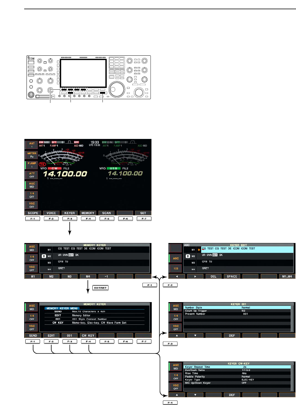
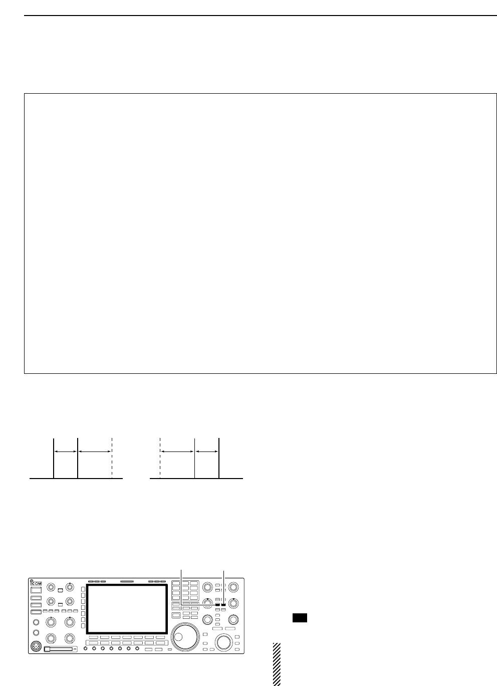
■Electronic keyer functions
The IC-7800 has a number of convenient functions for
the electronic keyer that can be accessed from the
memory keyer menu.
qDuring CW mode, push [EXIT/SET] several times
to normal screen, if necessary.
wPush [F-3•KEYER] to select memory keyer screen.
ePush [EXIT/SET] to select memory keyer menu
screen.
rPush one of the multi-function keys ([F-1] to [F-4]) to
select the desired menu. See the diagram below.
• Push [EXIT/SET] to return to the previous indication.
• Memory keyer screen (p. 4-8)
• Memory keyer menu screen
• Memory keyer edit screen (p. 4-9)
• Contest number set mode (p. 4-10)
• Keyer set mode screen (p. 4-11)
[EXIT/SET][CW][F-1]–[F-4]
4
RECEIVE AND TRANSMIT
4-8
DMemory keyer screen
Pre-set characters can be sent using the keyer send
menu. Contents of the memory keyer are set using the
edit menu.
• Transmitting
qDuring CW mode operation, push [F-3•KEYER] to
select memory keyer screen.
wPush [TRANSMIT] to set the transceiver to trans-
mit, or set the break-in function ON (p. 6-3).
ePush one of the function keys ([F-1•M1] to [F-4•M4])
to send the contents of the memory keyer.
• Pushing a function key for 1 sec. repeatedly sends the
contents; push any function key to cancel the transmis-
sion.
• The contest number counter, above [F-5•–1], is incre-
mented each time the contents are sent.
• Push [F-5•–1] to reduce the contest number count by 1
when resending contents to unanswered calls.
For your information
When an external keypad is connected to [EXT
KEYPAD] connector on the rear panel, the pro-
grammed contents, M1—M4, can be transmitted
without selecting the memory keyer screen.
See p. 2-6 for details.
rPush [EXIT/SET] twice to return to normal screen.
[CW][TRANSMIT] [F-1•M1]–[F-5•–1][EXIT/SET]
4RECEIVE AND TRANSMIT
• Memory keyer screen
4-9
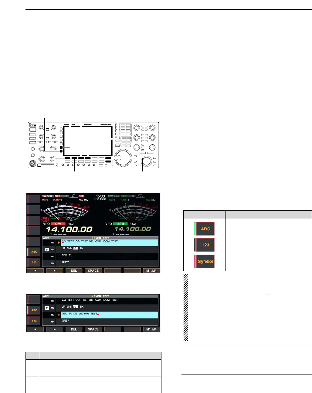
DEditing a memory keyer
The contents of the memory keyer memories can be
set using the memory keyer edit menu. The memory
keyer can memorize and re-transmit 4 CW key codes
for often-used CW sentences, contest numbers, etc.
Total capacity of the memory keyer is 70 characters
per memory channel.
• Programming contents
qDuring CW mode operation, push [F-3•KEYER] to
select memory keyer screen.
wPush [EXIT•SET] to select memory keyer menu,
then push [F-2•EDIT] to select keyer edit screen.
• Memory keyer contents of the Channel 1 (M1) is se-
lected.
ePush [F-7•M1..M4] several times to select the de-
sired memory keyer channel to be edited.
• Push [F5] to manually increment the contest number.
rPush [ABC] or [123] or [Symbol] to select the char-
acter group, then rotate the main dial to select the
character, or push the keypad for number input.
• [Symbol] appears when [123] is pushed when “123”
character group is selected.
• Selectable characters (with the main dial);
NOTE:
“^” is used to transmit a following word with no
space such as AR. Put “^” before a text string
such as ^AR, and the string “AR ” is sent with no
space.
“✱” is used to insert the CW contest number. The
contest number automatically increments by 1.
This function is only available for one memory
keyer channel at a time. Memory keyer channel
M2 used “✱” by default.
✔
For your convenience
When a PC keyboard is connected to [KEYBOARD]
connector on the rear panel, the memory keyer con-
tents can also be edited from the keyboard.
tPush [F-1•Ω] or [F-2•≈] to move the cursor back-
wards or forwards, respectively.
• Pushing [F-3•DEL] deletes a character and [F-4•SPACE]
inserts a space.
yRepeat steps rand tto input the desired charac-
ters.
uPush [EXIT/SET] twice to return normal screen.
[F-1•Ω]
[ABC][123]/[Symbol]
[F-7•M1..M4][EXIT/SET][F-2•≈]
[F-3•DEL] [F-4•SPACE]
4
RECEIVE AND TRANSMIT
• Memory keyer edit screen
Key selection Editable characters
A to Z (capital letters)
0 to 9 (numbers)
/ ? ^ . , ✱
• Example— entered “QSL TU DE JA3YUA TEST”
into memory keyer channel 3
CH Contents
M1 CQ TEST CQ TEST DE ICOM ICOM TEST
M2 UR 5NN✱BK
M3 CFM TU
M4 QRZ?
• Pre-programmed contents
4-10
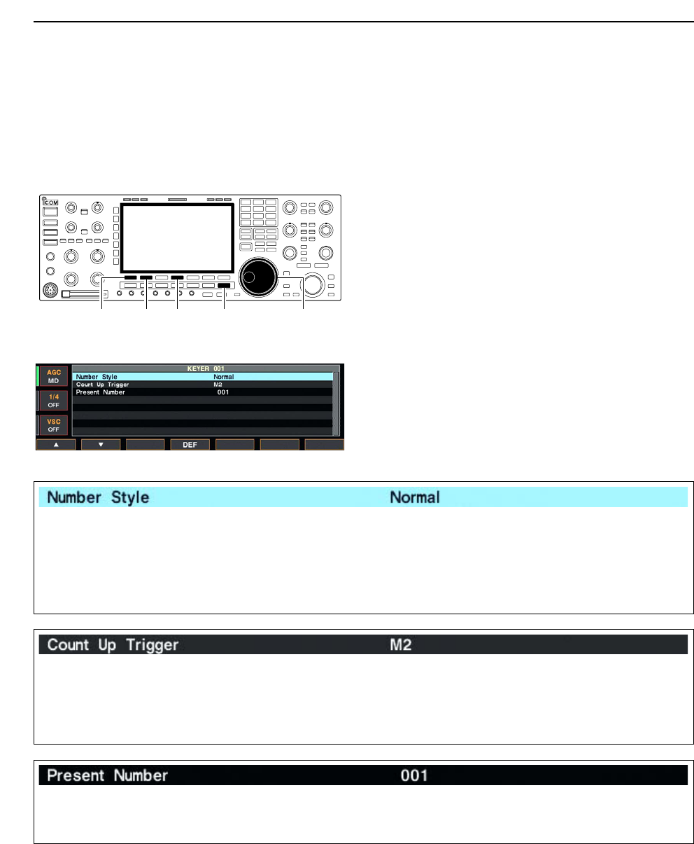
DContest number set mode
This menu is used to set the contest (serial) number
and count up trigger, etc.
• Setting contents
qDuring CW mode operation, push [F-3•KEYER] to
select memory keyer screen.
wPush [EXIT•SET] to select memory keyer menu,
then push [F-3•001] to select contest number set
mode.
ePush [F-1•Y] or [F-2•Z] to select the desired set
item.
rSet the desired condition using the main dial.
• Push [F-4•DEF] for 1 sec. to select the default condition
or value.
• Contest number set mode screen tPush [EXIT/SET] twice to normal screen.
[F-1•Y] Main dial[EXIT/SET][F-2•Z][F-4•DEF]
4RECEIVE AND TRANSMIT
This item sets the numbering system used for contest
(serial) numbers— normal or morse cut numbers.
• Normal : Does not use morse cut number
(default)
• 190➔ANO : Sets 1 as A, 9 as N and 0 as O.
• 190➔ANT : Sets 1 as A, 9 as N and 0 as T.
•90➔NO : Sets 9 as N and 0 as O.
•90➔NT : Sets 9 as N and 0 as T.
This selects which of the four memory slots will have
the contest serial number exchange. The count up
trigger allows the serial number automatically incre-
mented after each complete serial number exchange
is sent.
• M1, M2, M3 and M4 can be set. (default: M2)
This item shows the current number for the count up
trigger channel set above.
• Rotate the main dial to change the number, or push
[F-3•001CLR] for 1 sec. to reset the current number
to 001.
4-11
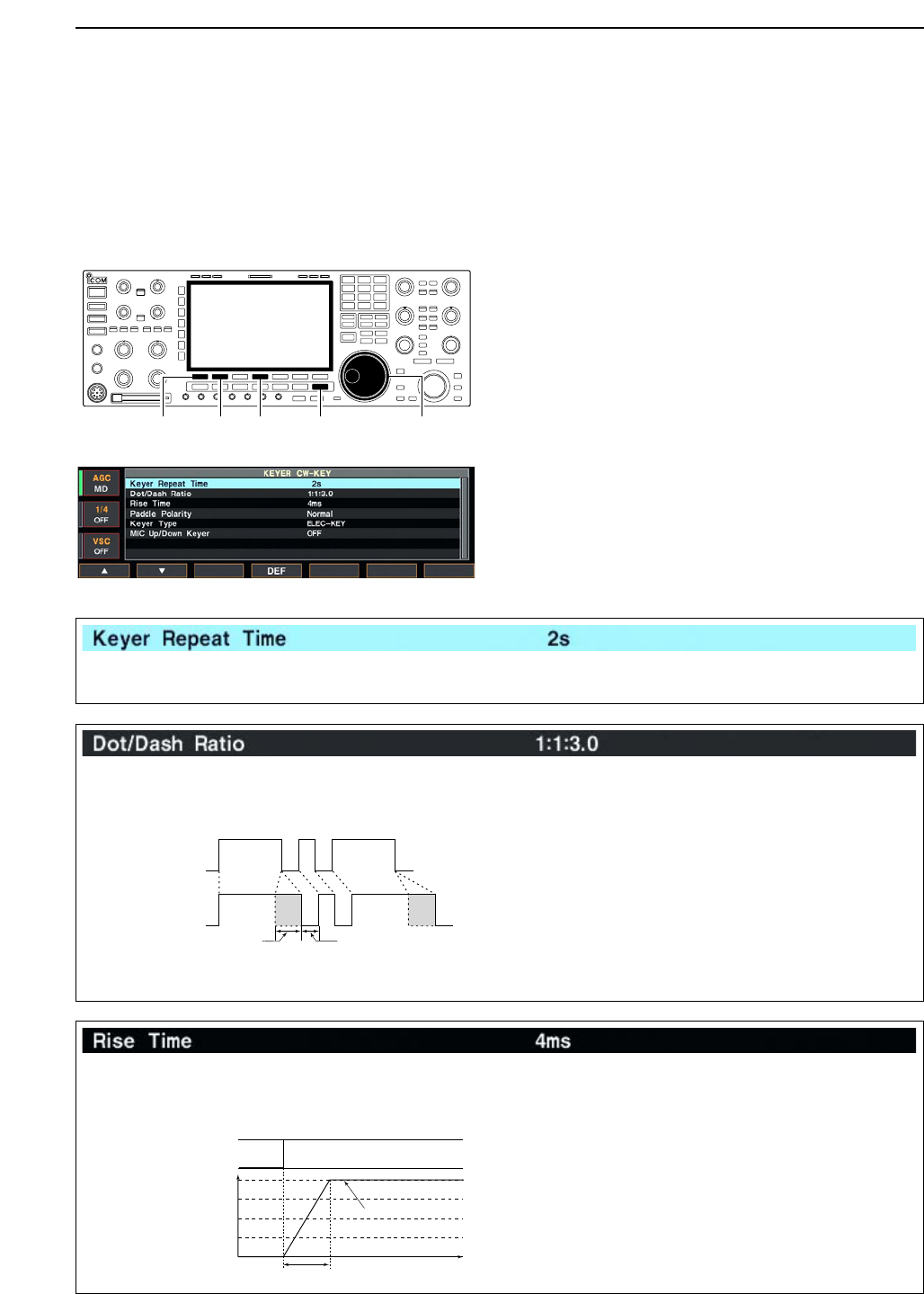
DKeyer set mode
This set mode is used to set the CW side tone, mem-
ory keyer repeat time, dash weight, paddle specifica-
tions, keyer type, etc.
• Setting contents
qDuring CW mode operation, push [F-3•KEYER] to
select memory keyer screen.
wPush [EXIT•SET] to select memory keyer menu,
then push [F-4•CW KEY] to select keyer set mode.
ePush [F-1•Y] or [F-2•Z] to select the desired set
item.
rSet the desired condition using the main dial.
• Push [F-4•DEF] for 1 sec. to select the default condition
or value.
• Keyer set mode screen tPush [EXIT/SET] twice to normal screen.
[F-1•Y] Main dial[EXIT/SET][F-2•Z][F-4•DEF]
4
RECEIVE AND TRANSMIT
When sending CW using the repeat timer, this item
sets the time between transmission.
• 1 to 60 sec. in 1 sec. steps can be selected.
(default: 2 sec.)
This item sets the dot/dash ratio.
Keying weight example: Morse code “K”
• 1:1:2.8 to 1:1:4.5 (in 0.1 steps) can be selected.
(default: 1:1:3.0)
DASH
Weight setting:
1:1:3 (default)
Weight setting:
Adjusted
DASH
DOT (fixed*)
Adjustable range SPACE (fixed*)
*SPACE and DOT length can be
adjusted with [KEY SPEED] only.
This item sets the envelop time period which the out-
put power becomes the set transmit power.
• 2, 4, 6 or 8 msec. can be selected. (default: 4 msec.)
Key action
Tx output power
• About rise time
Rise time
Tx
Rx
Set Tx power level
Time
0
to be continued…
4-12
DKeyer set mode (continued)
4RECEIVE AND TRANSMIT
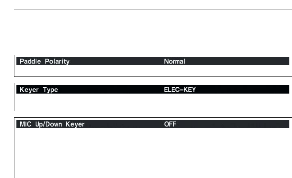
This item sets the paddle polarity. • Normal and reverse polarity can be selected.
This item selects the keyer type for [ELEC-KEY] con-
nector on the front panel.
• ELEC-KEY, BUG-KEY and Straight key can be se-
lected. (default: ELEC-KEY)
This item allows you to set the microphone [UP]/[DN]
keys to be used as a paddle.
•ON :[UP]/[DN] switches can be used for CW.
•OFF :[UP]/[DN] switches cannot be used for
CW.
NOTE: When “ON” is selected, the frequency and
memory channel cannot be changed using
the [UP]/[DN] switches.
4-13
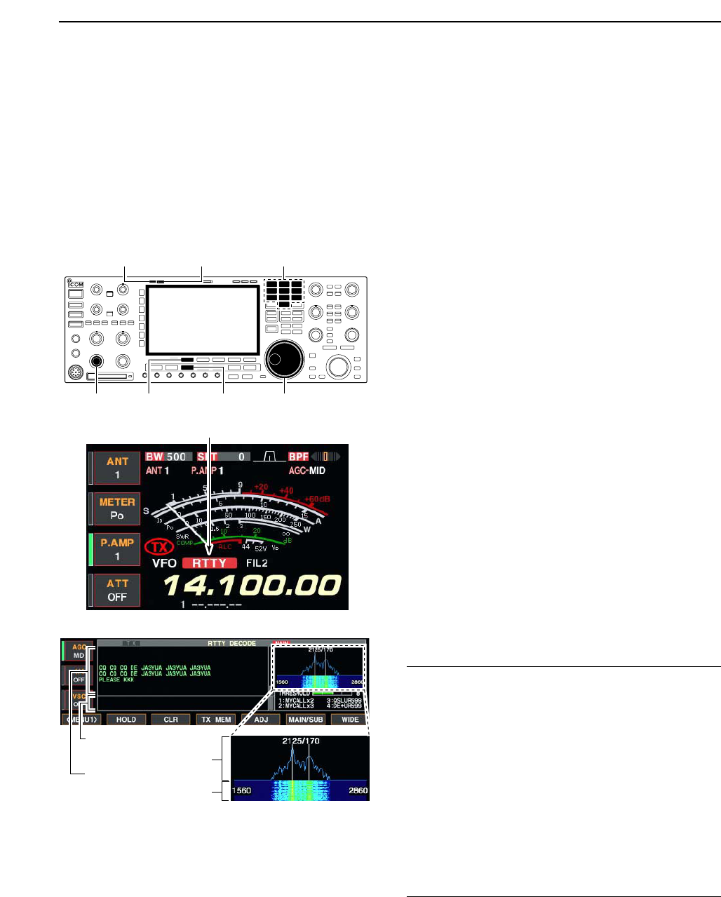
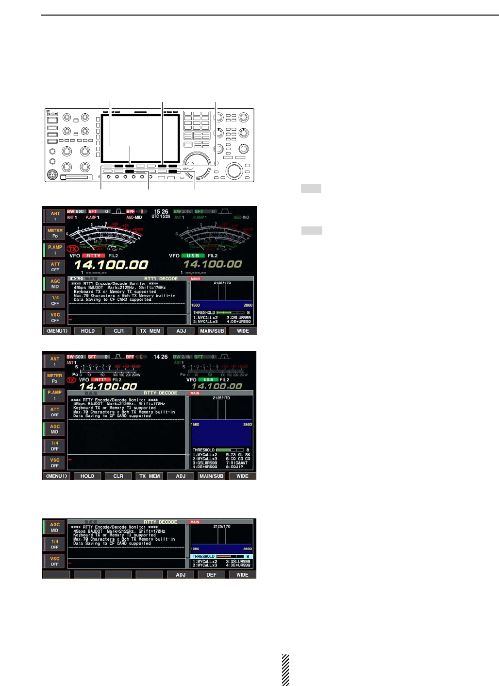
■Operating RTTY (FSK)
The Baudot RTTY encoder/decoder is built-in to the IC-
7800. When connecting a PC keyboard (p. 2-6), RTTY
operation can be performed without an external RTTY
terminal, TNC, etc.
When using your RTTY terminal or TNC, consult the
manual that comes with the RTTY terminal or TNC.
qPush a band key to select the desired band.
wPush [RTTY/PSK] to select RTTY.
• After RTTY mode is selected, push [RTTY/PSK] for
1 sec. to toggle between RTTY and RTTY-R modes.
• “RTTY” or “RTTY-R” appears.
ePush [F-3•DECODE] to display the decoder screen.
• The IC-7800 has a Baudot decoder.
rTo tune into the desired signal, make symmetrical
wave form and ensure the waves peak points align
with the mark (2125 Hz) and shift (170 Hz) fre-
quency lines in the FFT scope with the main dial.
• The S-meter indicates received signal strength when
signal is received.
tRotate [AF] to set the audio to a comfortable listen-
ing level.
yPress [F12] of the connected keyboard to transmit.
• [TX] indicator lights red.
uType from the connected keyboard to enter the con-
tents that you want to transmit.
• The typewritten contents are indicated in the TX buffer
screen and transmitted immediately.
• The text color will be changed when transmitted.
• Press one of [F1]–[F8] to transmit the TX memory con-
tents.
iPress [F12] of the keyboard to return to receive.
✔
For your convenience
The transmission contents can be typewritten before
being transmitted.
qPerform the steps qto rabove.
wType from the connected keyboard to enter the con-
tents that you want to transmit.
• The typewritten contents are indicated in the TX buffer
screen.
ePress [F12] of the connected keyboard to transmit
the typewritten contents.
• The color of displayed text, in the TX buffer screen, will
be changed when transmitted.
• To cancel the transmission, press [F12] twice.
rPress [F12] of the keyboard to return to receive.
FFT scope
TX buffer screen
RX contents screen
Water-fall
Appears
[TX] indicator [RX] indicator
[F-3•DECODE] [RTTY/PSK][AF] Main dial
Band keys
4
RECEIVE AND TRANSMIT
4-14
DConvenient functions for receive
DAbout RTTY reverse mode
Received characters are occasionally garbled when
the receive signal is reversed between MARK and
Space. This reversal can be caused by incorrect TNC
connections, setting, commands, etc. To receive re-
versed RTTY signals correctly, select RTTY-R mode.
➥During RTTY mode, push [RTTY/PSK] for 1 sec. to
select RTTY and RTTY-R mode.
DTwin peak filter
The twin peak filter changes receive frequency re-
sponse by boosting 2 particular frequencies (2125 and
2295 Hz) for better copying of desired RTTY signals.
➥During RTTY mode, push [APF/TPF] to turn the twin
peak filter ON and OFF.
• “ ” appears in the LCD and the [APF/TPF] indicator
above this switch lights green while the filter is in use.
NOTE: When the twin peak filter is in use, the re-
ceived audio output may be increased. This is a nor-
mal transceiver performance to providing a better
decoding, not a malfunction.
TPF
[APF/TPF]
(SUB)
[APF/TPF]
(MAIN)
Normal Reverse
Space Mark BFO Space Mark
BFO
170 Hz 2125 Hz 170 Hz2125 Hz
• Preamp (p. 5-9)
➥Push [P.AMP] several times to set the preamp
OFF, preamp 1 ON or preamp 2 ON.
• “P.AMP1” or “P.AMP2” appears when the preamp 1 or
preamp 2 is set to ON, respectively. (depending on
operating frequency band)
• Attenuator (p. 5-9)
➥Push [ATT] several times to set the attenuator in
6 dB steps.
• Pushing [P.AMP] for 1 sec. to set the attenuator in
3 dB steps.
• “ATT” and attenuation level appear when the attenu-
ator is set to ON.
• Noise blanker (p. 5-17)
➥Push [NB] switch to turn the noise blanker ON
and OFF, and then rotate [NB] control to adjust
the threshold level.
• Noise blanker indicator (above [NB] switch) lights
when the noise blanker is set to ON.
• Push [NB] for 1 sec. to enter noise blanker set mode.
• Twin PBT (passband tuning) (p. 5-12)
➥Rotate [TWIN PBT] controls (inner/outer).
• Push [PBT CLEAR] to clear the settings.
• Noise reduction (p. 5-18)
➥Push [NR] switch to turn the noise reduction ON
and OFF.
• Rotate [NR] control to adjust the noise reduction
level.
• Noise reduction indicator (above [NR] switch) lights
when the noise reduction is set to ON.
• Auto notch filter (p. 5-19)
➥Push [NOTCH] switch to turn the manual notch
function ON and OFF.
• Rotate [NOTCH] control to set the attenuating fre-
quency.
• Notch indicator (above [NOTCH] switch) lights when
either the manual notch is set to ON.
• AGC (auto gain control) (p. 5-11)
➥Push [AGC] switch several times to select
AGC FAST, AGC MID or AGC SLOW.
➥Push [AGC VR] to turn the AGC time constant
manual setting ON and OFF.
• Rotate [AGC] control to adjust the time constant.
•1⁄4function (p. 3-6)
➥Push [1/4] to turn the 1⁄4function ON and OFF.
4RECEIVE AND TRANSMIT
4-15
DFunctions for the RTTY decoder indication
qPush a band key to select the desired band.
wPush [RTTY/PSK] to select RTTY.
• After RTTY mode is selected, push [RTTY/PSK] for
1 sec. to toggle between RTTY and RTTY-R modes.
• “RTTY” or “RTTY-R” appears.
ePush [F-3•DECODE] to display the decoder screen.
• When tuned into an RTTY signal, decoded characters
are displayed in the RX contents screen.
rPush [F-2•HOLD] to freeze the current screen.
• “ ” appears while the function is in use.
• Push [F-2•HOLD] again to release the function.
tPush [F-3•CLR] for 1 sec. to clear the displayed
characters.
•“ ” indicator disappears at the same time when the
hold function is in use.
yPush [F-7•WIDE] to toggle the RTTY decode screen
size from normal and wide.
• S/RF meter type during wide screen indication can be
selected in display set mode. (pgs. 3-11, 12-11)
uPush [F-6•MAIN/SUB] to toggle the MAIN and SUB
band for decode operation.
• Dualwatch function (p. 5-16) should be ON when SUB
band is selected for decode operation.
iPush [EXIT/SET] to close the RTTY decode screen.
• Wide screen indication
DSetting the decoder threshold level
Adjust the RTTY decoder threshold level if some char-
acters are displayed when no signal is received.
qCall up the RTTY decoder screen as described
above.
wPush [F-5•ADJ] to select the threshold level setting
condition.
eRotate the main dial to adjust the RTTY decoder
threshold level.
• Push [F-6•DEF] for 1 sec. to select the default setting.
rPush [F-5•ADJ] to exit from the threshold level set-
ting condition.
The UnShift On Space (USOS) function and new
line code can be set in the RTTY set mode. (p. 4-
18)
HOLD
HOLD
[F-3•CLR] [F-6•MAIN/SUB] [F-7•WIDE]
[F-2•HOLD] [RTTY/PSK] [EXIT/SET]
4
RECEIVE AND TRANSMIT
4-16
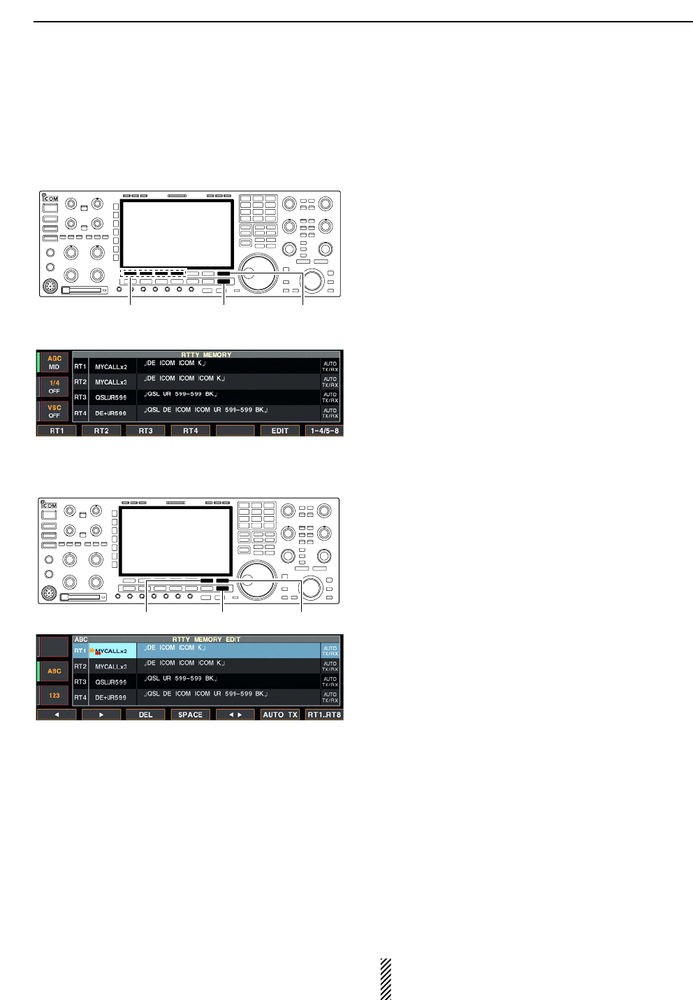
DRTTY memory transmission
Pre-set characters can be sent using the RTTY mem-
ory. Contents of the memory are set using the edit
menu.
qDuring RTTY mode operation, push [F-3•DECODE]
to select RTTY decode screen.
wPush [F-4•TX MEM] to select RTTY memory
screen.
ePush [F-7•1–4/5–8] to select memory bank then
push one of the function keys ([F-1•RT1] to
[F-4•RT4] or [F-1•RT5] to [F-4•RT8]).
• When no keyboard is connected, the selected memory
contents will be transmitted immediately.
• When a keyboard is connected, the memory contents
will be transmitted immediately when function key is
pushed, or transmitted after [F12] on the connected key-
board is pressed, depending on auto transmission/re-
ception setting (see below).
• The transmission date, time, reception date and/or time
may be displayed in RX contents screen, depending on
setting.
DAutomatic transmission/reception setting
qDuring RTTY mode operation, push [F-3•DECODE]
to select RTTY decode screen.
wPush [F-4•TX MEM] to select RTTY memory
screen, then push [F-6•EDIT] to select RTTY mem-
ory edit screen.
•RTTY memory contents of the Channel 1 (RT1) is se-
lected.
ePush [F-7•RT1..RT8] several times to select the de-
sired RTTY memory.
rPush [F-6•AUTO TX] several times to select the de-
sired condition as follow.
• AUTO TX/RX : Automatically transmits the se-
lected memory and returns to re-
ceive after the transmission.
• AUTO TX : Automatically transmits the se-
lected memory. To return to re-
ceive, press [F12] on the key-
board.
• AUTO RX : Press [F12] on the keyboard to
transmit the selected memory. Au-
tomatically returns to receive after
the transmission.
• No indication : Press [F12] on the keyboard to
transmit the selected memory and
press [F12] again to return to re-
ceive.
tPush [EXIT/SET] to exit RTTY memory edit condi-
tion.
NOTE: The transceiver always functions as the
“AUTO TX/RX” setting when no keyboard is con-
nected.
[F-6•AUTO TX] [F-7•RT1..RT8][EXIT/SET]
[F-7•1–4/5–8][F-1•RT1]–[F-4•RT4]
[F-1•RT5]–[F-4•RT8]
[EXIT/SET]
4RECEIVE AND TRANSMIT
4-17
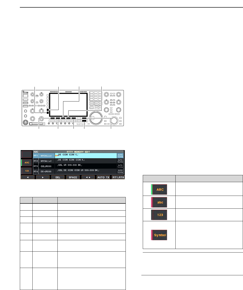
DEditing RTTY memory
The contents of the RTTY memories can be set using
the memory edit menu. The memory can memorize
and re-transmit 8 RTTY contents for often-used RTTY
sentences. Total capacity of the memory is 70 charac-
ters per memory channel.
• Programming contents
qDuring RTTY mode operation, push [F-3•DECODE]
to select RTTY decode screen.
wPush [F-4•TX MEM] to select RTTY memory
screen, then push [F-6•EDIT] to select RTTY mem-
ory edit screen.
• RTTY memory contents of the Channel 1 (RT1) is se-
lected.
ePush [F-7•RT1..RT8] to several times to select the
desired RTTY memory channel to be edited.
rPush [F-5•Ω≈] to select the edit item between
memory contents and memory name.
tPush [ABC], [abc], [123] or [Symbol] to select the
character group, then rotate the main dial to select
the character, or push the keypad for number input.
• [abc] appears when [ABC] is pushed when “ABC” char-
acter group is selected, and [Symbol] appears when
[123] is pushed when “123” character group is selected.
• Selectable characters (with the main dial);
✔
For your convenience
When a PC keyboard is connected to [KEYBOARD]
connector on the rear panel, the RTTY memory
contents can also be edited from the keyboard.
yPush [F-1•Ω] or [F-2•≈] to move the cursor back-
wards or forwards, respectively.
• Pushing [F-3•DEL] deletes a character and [F-4•SPACE]
inserts a space.
uRepeat steps tand yto input the desired charac-
ters.
iPush [EXIT/SET] to set the contents and exit RTTY
memory edit screen.
[F-1•Ω]
[ABC]/[abc][123]/[Symbol]
[F-7•RT1..RT8][EXIT/SET][F-2•≈]
[F-3•DEL] [F-4•SPACE]
[F-5•Ω≈]
4
RECEIVE AND TRANSMIT
• RTTY memory edit screen
Key selection Editable characters
A to Z (capital letters)
a to z (small letters)
(selectable for memory name only)
0 to 9 (numbers)
! # $ % & ¥ ? “ ‘ ` ^ + – ✱/ . , : ; =
< > ( ) [ ] { } | _ ~@
(For the memory contents set-
ting, ! $ & ? “ ‘ – / . , : ; ( ) ↵are
selectable.)
CH Name Contents
RT1 MYCALLx2 ↵DE ICOM ICOM K↵
RT2 MYCALLx3 ↵DE ICOM ICOM ICOM K↵
RT3 QSLUR599 ↵QSL UR 599–599 BK↵
RT4 DE+UR599 ↵QSL DE ICOM ICOM UR 599–599
BK↵
RT5 73 GL SK ↵73 GL SK↵
RT6 CQ CQ CQ ↵CQ CQ CQ DE ICOM ICOM ICOM
K↵
RT7 RIG&ANT ↵MY TRANSCEIVER IS IC–7800 &
ANTENNA IS A 3–ELEMENT
TRIBAND YAGI.↵
RT8 EQUIP. ↵MY RTTY EQUIPMENT IS
INTERNAL FSK UNIT &
DEMODULATOR OF THE
IC–7800.↵
• Pre-programmed contents
4-18
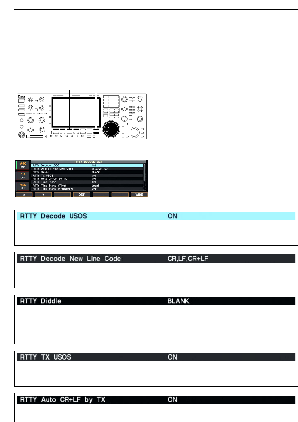
DRTTY decode set mode
This set mode is used to set the decode USOS func-
tion, time stamp setting, etc.
• Setting contents
qDuring RTTY mode operation, push [F-3•DECODE]
to select RTTY decode screen.
wPush [F-1•<MENU2>] to select RTTY decode menu
2, then push [F-6•SET] to select RTTY decode set
mode.
• Push [F-7•WIDE] to toggle the screen size from normal
and wide.
ePush [F-1•Y] or [F-2•Z] to select the desired set
item.
rSet the desired condition using the main dial.
• Push [F-4•DEF] for 1 sec. to select a default condition
or value.
• Push [F-3•Ω≈] to select the set contents for some
items.
tPush [EXIT/SET] to exit from set mode.
[F-1•Y] Main dial[EXIT/SET][F-2•Z][F-4•DEF]
[F-3•Ω ≈] [F-7•WIDE]
4RECEIVE AND TRANSMIT
• RTTY decode set mode screen
Turn the letter code decoding after receiving a “space”
(USOS; UnShift On Space function) capability ON
and OFF.
• ON : Decode as letter code.
• OFF : Decode as character code.
Selects the new line code of the internal RTTY de-
coder.
CR: Carriage Return, LF: Line Feed
• CR,LF,CR;LF : Makes new line with any codes.
• CR+LF : Makes new line with CR+LF code
only.
Selects the diddle condition. • BLANK : Transmits blank code during no code
transmission.
• LTRS : Transmits letter code during no code
transmission.
• OFF : Turns the diddle function OFF.
Selects the FIGS insertion even changing from LTRS
to FIGS does not necessary when sending a numeral
or symbol character after a space.
• ON : Inserts FIGS.
• OFF : Not insert FIGS.
Selects the automatic new line code (CR+LF) trans-
mission capability.
• ON : Transmits CR+LF code once.
• OFF : Transmits no CR+LF code.
4-19
DRTTY decode set mode (continued)
4
RECEIVE AND TRANSMIT
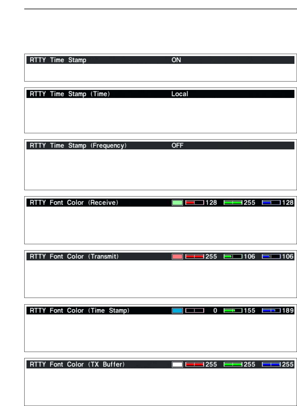
Turn the time stamp (date, transmission or reception
time) indication ON and OFF.
• ON : Indicates the time stamp.
• OFF : No time stamp indication.
Selects the clock indication for time stamp usage.
NOTE: The time won’t be displayed when “OFF” is
selected in “RTTY Time Stamp” as above.
• Local : Selects the time that set in “Time (Now).”
• UTC* : Selects the time that set in “CLOCK2.”
*The name of choice may differ according to
“CLOCK2 Name” setting (p, 11-2). “UTC” is the
default name setting of CLOCK2.
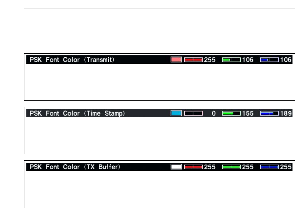
Set the text color for transmitted characters. • The color is set in RGB format.
• Push [F-3•Ω≈] to select R (Red), G (Green) and B
(Blue), and rotate the ratio from 0 to 255 range.
• The set color is indicated in the box beside the RGB
scale.
Selects the operating frequency indication for time
stamp usage.
NOTE: The frequency won’t be displayed when
“OFF” is selected in “RTTY Time Stamp” as
above.
• ON : Indicates the operating frequency.
• OFF : No operating frequency indication.
Set the text color for received characters. • The color is set in RGB format.
• Push [F-3•Ω≈] to select R (Red), G (Green) and B
(Blue), and rotate the ratio from 0 to 255 range.
• The set color is indicated in the box beside the RGB
scale.
Set the text color for time stamp indication. • The color is set in RGB format.
• Push [F-3•Ω≈] to select R (Red), G (Green) and B
(Blue), and rotate the ratio from 0 to 255 range.
• The set color is indicated in the box beside the RGB
scale.
Set the text color in the TX buffer screen. • The color is set in RGB format.
• Push [F-3•Ω≈] to select R (Red), G (Green) and B
(Blue), and rotate the ratio from 0 to 255 range.
• The set color is indicated in the box beside the RGB
scale.
4-20
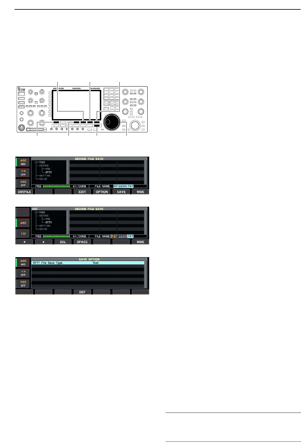
DData saving
The contents of the RTTY memory and received sig-
nal can be saved into the CF memory card.
qDuring RTTY decode screen indication, push
[F-1•<MENU1>] to select RTTY decode menu 2.
wPush [F-5•SAVE] to select decode file save screen.
eChange the following conditions if desired.
• File name:
zPush [F-4•EDIT] to select file name edit con-
dition.
• Push [F-1• DIR/FILE] several times to select the
file name, if necessary.
xPush [ABC], [123] or [Symbol] to select the
character group, then rotate the main dial to
select the character.
• [ABC] : A to Z (capital letters); [123]: 0 to 9 (nu-
merals); [Symbol]: ! # $ % & ‘ ` ^ + – = ( ) [ ] { } _ ~
@ can be selected.
• Push [F-1•Ω] to move the cursor left, push [F-2•≈]
to move the cursor right, [F-3•DEL] delete a char-
acter and push [F-4•SPACE] to insert a space.
cPush [EXIT/SET] to set the file name.
• File format
zPush [F-5•OPTION] to enter save option
screen.
xRotate the main dial to select the saving for-
mat from Text and HTML.
• “Text” is the default setting.
• Push [F-4•DEF] for 1 sec. to select the default set-
ting.
cPush [EXIT/SET] to return to the previous in-
dication.
• Saving location
zPush [F-1•DIR/FILE] to select tree view
screen.
xSelect the desired directory or folder in the CF
memory card.
• Push [F-4•Ω≈] to select the upper directory.
• Push [F-2•Y] or [F-3•Z] to select folder in the
same directory.
• Push [F-4•Ω≈] for 1 sec. to select a folder in the
directory.
• Push [F-5•REN/DEL] to rename the folder.
• Push [F-5•REN/DEL] for 1 sec. to delete the
folder.
• Push [F-6•MAKE] for 1 sec. to making a new
folder. (Edit the name with the same manner as
the “• File name” above.)
cPush [F-1•DIR/FILE] twice to select the file
name.
rPush [F-6•SAVE].
• After the saving is completed, return to RTTY decode
menu 2 automatically.
[F-1•DIR/FILE] Main dial[EXIT/SET][F-4•EDIT]
[F-5•OPTION] [F-6•SAVE] [F-7•WIDE]
4RECEIVE AND TRANSMIT
• Decode file save screen
• Decode file save screen— file name edit
• Save option screen
✔
For your convenient!
Both of data formats, Text and HTML, are compatible
data format in a PC. The saved data can be copied to
your PC for record, etc.
4-21
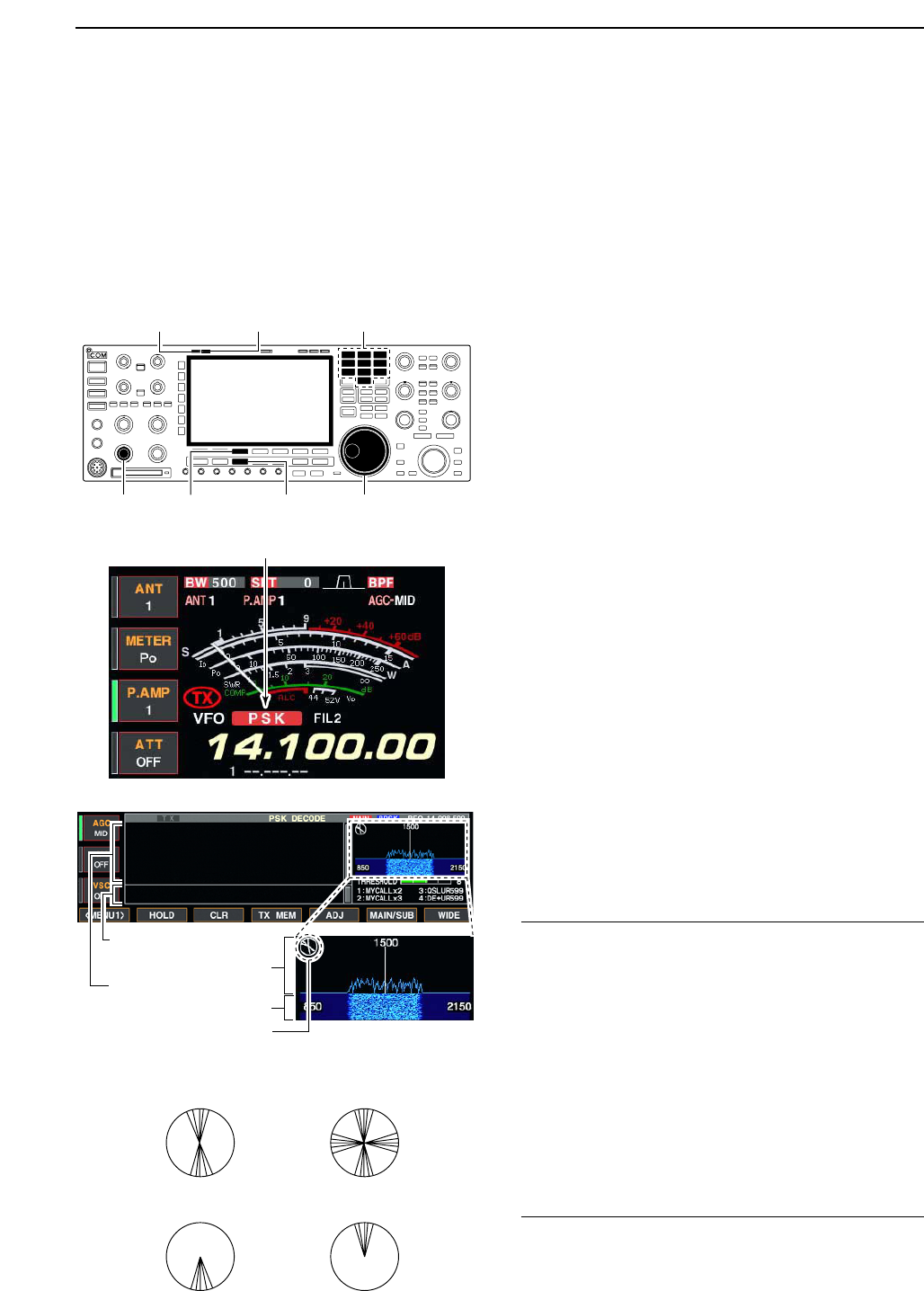
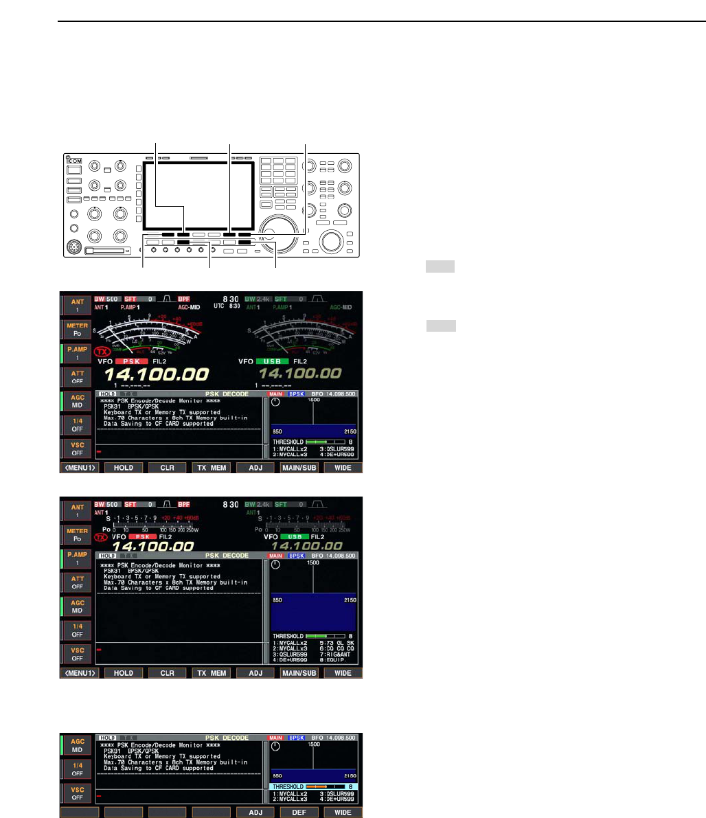
■Operating PSK
The PSK31 encoder/decoder is built-in to the IC-7800.
When connecting a PC keyboard (p. 2-6), PSK31 op-
eration can be performed without a PSK operation soft-
ware installed PC.
When using your PSK operation software, consult the
manual that comes with the software.
qPush a band key to select the desired band.
wPush [RTTY/PSK] to select PSK.
• After PSK mode is selected, push [RTTY/PSK] for 1 sec.
to toggle between PSK and PSK-R modes.
• “PSK” or “PSK-R” appears.
e
Push [F-3•DECODE] to displays the decoder screen.
• The IC-7800 has a PSK31 decoder.
rTune to the desired signal with the main dial.
• The signal is tuned when the radiated lines in the vector
tuning indicator narrow as in the example below.
• The radiated lines in the vector tuning indicator are dis-
played in sporadically.
• When a PSK signal is received, the water-fall indicator is
activated.
• The water-fall indicator shows the signal condition within
the passband width and a vertical line appears when a
PSK signal is received.
tRotate [AF] to set the audio to a comfortable listen-
ing level.
yPress [F12] of the connected keyboard to transmit.
• [TX] indicator lights red.
uType from the connected keyboard to enter the con-
tents that you want to transmit.
• The typewritten contents are indicated in the TX buffer
screen and transmitted immediately.
• The text color will be changed when transmitted.
• Press one of [F1]–[F8] to transmit the TX memory con-
tents.
iPress [F12] of the keyboard to return to receive.
oPush [TRANSMIT] to return to receive.
✔
For your convenience
The transmission contents can be typewritten before
being transmit.
qPerform the steps qto rabove.
wType from the connected keyboard to enter the con-
tents that you want to transmit.
• The typewritten contents are indicated in the TX buffer
screen.
ePress [F12] of the connected keyboard to transmit
the typewritten contents.
• The color of displayed text, in the TX buffer screen, will
be changed when transmitted.
• To cancel the transmission, press [F12] twice.
rPress [F12] of the keyboard to return to receive.
FFT scope
Vector tuning indicator
TX buffer screen
RX contents screen
Water-fall
Appears
[TX] indicator [RX] indicator
[F-3•DECODE] [RTTY/PSK][AF] Main dial
Band keys
4
RECEIVE AND TRANSMIT
• Vector tuning indicator indication example
Tuned BPSK signal
BPSK/QPSK idle signal Unmodulated signal
Tuned QPSK signal
4-22
DConvenient functions for receive
DAbout BPSK and QPSK mode
BPSK and QPSK modes are available for the PSK31.
• BPSK (Binary Phase Shift Keying) mode is the most
often used mode.
• QPSK (Quadrature Phase Shift Keying) mode has
error correction capability to provides a better decod-
ing than BPSK mode operation even in a worth con-
dition. However, much accurate tuning is required
with the QPSK mode, due to the QPSK mode has
only few phase margin.
qDuring PSK mode selection, push [F-3•DECODE]
to display the PSK decode screen.
wPush [F-1•<MENU1>] to select PSK decode menu
2.
ePush [F-2•B/QPSK] to toggle between BPSK and
QPSK mode alternately.
[F-3•DECODE][F-2•B/QPSK][F-1•<MENU1>]
• Preamp (p. 5-9)
➥Push [P.AMP] several times to set the preamp
OFF, preamp 1 ON or preamp 2 ON.
• “P.AMP1” or “P.AMP2” appears when the preamp 1 or
preamp 2 is set to ON, respectively. (depending on
operating frequency band)
• Attenuator (p. 5-9)
➥Push [ATT] several times to set the attenuator in
6 dB steps.
• Pushing [P.AMP] for 1 sec. to set the attenuator in
3 dB steps.
• “ATT” and attenuation level appear when the attenu-
ator is set to ON.
• Noise blanker (p. 5-17)
➥Push [NB] switch to turn the noise blanker ON
and OFF, and then rotate [NB] control to adjust
the threshold level.
• Noise blanker indicator (above [NB] switch) lights
when the noise blanker is set to ON.
• Push [NB] for 1 sec. to enter noise blanker set mode.
• Twin PBT (passband tuning) (p. 5-12)
➥Rotate [TWIN PBT] controls (inner/outer).
• Push [PBT CLEAR] to clear the settings.
• Noise reduction (p. 5-18)
➥Push [NR] switch to turn the noise reduction ON
and OFF.
• Rotate [NR] control to adjust the noise reduction
level.
• Noise reduction indicator (above [NR] switch) lights
when the noise reduction is set to ON.
• AGC (auto gain control) (p. 5-11)
➥Push [AGC] switch several times to select
AGC FAST, AGC MID or AGC SLOW.
➥Push [AGC VR] to turn the AGC time constant
manual setting ON and OFF.
• Rotate [AGC] control to adjust the time constant.
• Fine tuning (p. 3-7)
➥During no kHz tuning step function OFF (no “Z”
indication), push [TS] for 1 sec.
• May not be decoded correctly with the 10 Hz step
tuning.
•1⁄4function (p. 3-6)
➥Push [1/4] to turn the 1⁄4function ON and OFF.
4RECEIVE AND TRANSMIT
• PSK decode screen— BPSK mode
• PSK decode screen— QPSK mode
4-23
DFunctions for the PSK decoder indication
qPush a band key to select the desired band.
wPush [RTTY/PSK] to select PSK.
• After PSK mode is selected, push [RTTY/PSK] for 1 sec.
to toggle between PSK and PSK-R modes.
• “PSK” or “PSK-R” appears.
ePush [F-3•DECODE] to display the decoder screen.
• When tuned into a PSK signal, decoded characters are
displayed in the RX contents screen.
rPush [F-2•HOLD] to freeze the current screen.
• “ ” appears while the function is in use.
• Push [F-2•HOLD] again to release the function.
tPush [F-3•CLR] for 1 sec. to clear the displayed
characters.
•“ ” indicator disappears at the same time when the
hold function is in use.
yPush [F-7•WIDE] to toggle the PSK decode screen
size from normal and wide.
• S/RF meter type during wide screen indication can be
selected in display set mode. (pgs. 3-11, 12-11)
uPush [F-6•MAIN/SUB] to toggle the MAIN and SUB
band for decode operation.
• Dualwatch function (p. 5-16) should be ON when SUB
band is selected for decode operation.
iPush [EXIT/SET] to close the PSK decode screen.
• Wide screen indication
DSetting the decoder threshold level
Adjust the PSK decoder threshold level if some char-
acters are displayed when no signal is received.
qCall up the PSK decoder screen as described
above.
wPush [F-5•ADJ] to select the threshold level setting
condition.
eRotate the main dial to adjust the PSK decoder
threshold level.
• Push [F-6•DEF] for 1 sec. to select the default setting.
rPush [F-5•ADJ] to exit from the threshold level set-
ting condition.
HOLD
HOLD
[F-3•CLR] [F-6•MAIN/SUB] [F-7•WIDE]
[F-2•HOLD] [RTTY/PSK] [EXIT/SET]
4
RECEIVE AND TRANSMIT
4-24
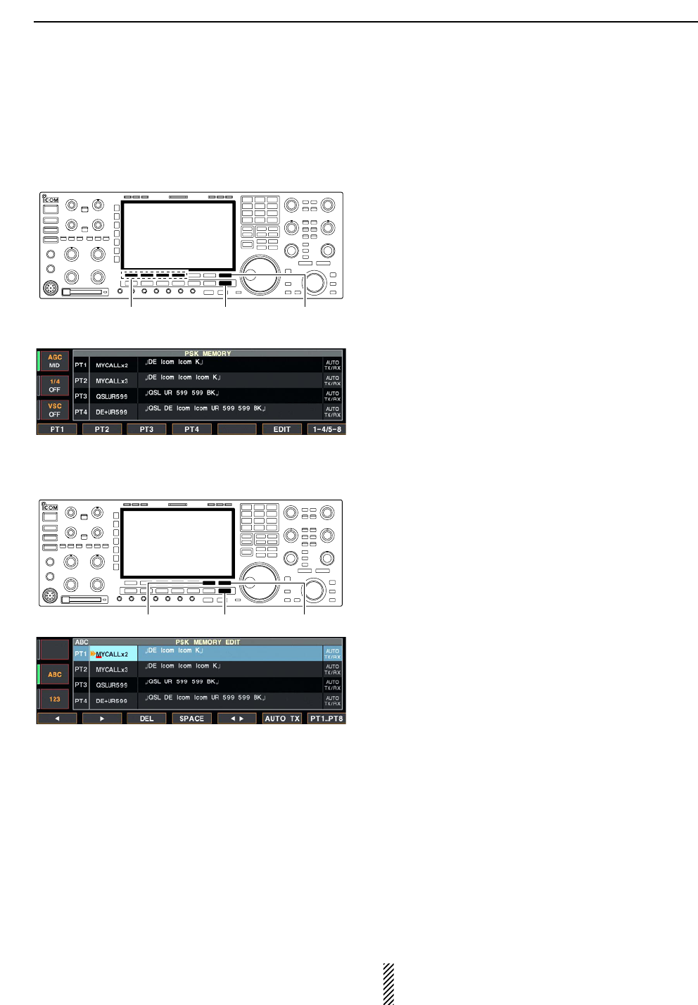
DPSK memory transmission
Pre-set characters can be sent using the PSK memo-
ry. Contents of the memory are set using the edit
menu.
qDuring PSK mode operation, push [F-3•DECODE]
to select PSK decode screen.
wPush [F-4•TX MEM] to select PSK memory screen.
ePush [F-7•1–4/5–8] to select memory bank then
push one of the function keys ([F-1•PT1] to
[F-4•PT4] or [F-1•PT5] to [F-4•PT8]).
• When no keyboard is connected, the selected memory
contents will be transmitted immediately.
• When a keyboard is connected, the memory contents
will be transmitted immediately when function key is
pushed, or transmitted after [F12] on the connected key-
board is pressed, depending on auto transmission/re-
ception setting (see below).
• The transmission date, time, reception date and/or time
may be displayed in RX contents screen, depending on
setting.
DAutomatic transmission/reception setting
qDuring PSK mode operation, push [F-3•DECODE]
to select PSK decode screen.
wPush [F-4•TX MEM] to select PSK memory screen,
then push [F-6•EDIT] to select PSK memory edit
screen.
• PSK memory contents of the Channel 1 (PT1) is se-
lected.
ePush [F-7•PT1..PT8] several times to select the de-
sired RTTY memory.
rPush [F-6•AUTO TX] several times to select the de-
sired condition as follow.
• AUTO TX/RX : Automatically transmits the se-
lected memory and returns to re-
ceive after the transmission.
• AUTO TX : Automatically transmits the se-
lected memory. To return to re-
ceive, press [F12] on the key-
board.
• AUTO RX : Press [F12] on the keyboard to
transmit the selected memory. Au-
tomatically returns to receive after
the transmission.
• No indication : Press [F12] on the keyboard to
transmit the selected memory and
press [F12] again to return to re-
ceive.
tPush [EXIT/SET] to return to exit from PSK mem-
ory edit condition.
NOTE: The transceiver always functions as the
“AUTO TX/RX” setting when no keyboard is con-
nected.
[F-6•AUTO TX] [F-7•PT1..PT8][EXIT/SET]
[F-7•1–4/5–8][F-1•PT1]–[F-4•PT4]
[F-1•PT5]–[F-4•PT8]
[EXIT/SET]
4RECEIVE AND TRANSMIT
4-25
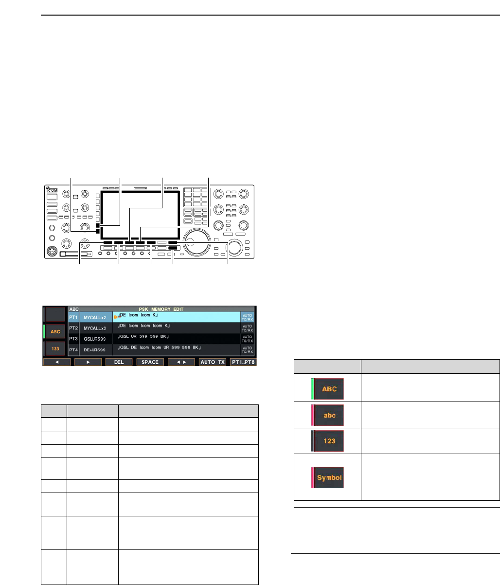
DEditing PSK memory
The contents of the PSK memories can be set using
the memory edit menu. The memory can memorize
and re-transmit 8 PSK contents for often-used PSK
sentences. Total capacity of the memory is 70 charac-
ters per memory channel.
• Programming contents
qDuring PSK mode operation, push [F-3•DECODE]
to select PSK decode screen.
wPush [F-4•TX MEM] to select PSK memory screen,
then push [F-6•EDIT] to select PSK memory edit
screen.
• PSK memory contents of the Channel 1 (PT1) is se-
lected.
ePush [F-7•PT1..PT8] several times to select the de-
sired PSK memory channel to be edited.
rPush [F-5•Ω≈] to select the edit item between
memory contents and memory name.
tPush [ABC], [abc], [123] or [Symbol] to select the
character group, then rotate the main dial to select
the character, or push the keypad for number input.
• [abc] appears when [ABC] is pushed when “ABC” char-
acter group is selected, and [Symbol] appears when
[123] is pushed when “123” character group is selected.
• Selectable characters (with the main dial);
✔
For your convenience
When a PC keyboard is connected to [KEYBOARD]
connector on the rear panel, the PSK memory con-
tents can also be edited from the keyboard.
yPush [F-1•Ω] or [F-2•≈] to move the cursor back-
wards or forwards, respectively.
• Pushing [F-3•DEL] deletes a character and [F-4•SPACE]
inserts a space.
uRepeat steps tand yto input the desired charac-
ters.
iPush [EXIT/SET] to set the contents and exit PSK
memory edit screen.
[F-1•Ω]
[ABC]/[abc][123]/[Symbol]
[F-7•PT1..PT8][EXIT/SET][F-2•≈]
[F-3•DEL] [F-4•SPACE]
[F-5•Ω≈]
4
RECEIVE AND TRANSMIT
Key selection Editable characters
A to Z (capital letters)
a to z (small letters)
0 to 9 (numbers)
! # $ % & ¥ ? “ ‘ ` ^ + – ✱/ . , : ; =
< > ( ) [ ] { } | _ ~@↵
(“↵” is for the memory contents set-
ting only.)
CH Name Contents
PT1 MYCALLx2 ↵DE Icom Icom K↵
PT2 MYCALLx3 ↵DE Icom Icom Icom K↵
PT3 QSLUR599 ↵QSL UR 599 599 BK↵
PT4 DE+UR599 ↵QSL DE Icom Icom UR 599 599
BK↵
PT5 73 GL SK ↵73 GL SK↵
PT6 CQ CQ CQ ↵CQ CQ CQ DE Icom Icom Icom
K↵
PT7 RIG&ANT ↵My transceiver is IC–7800 &
Antenna is a 3–element triband
yagi.↵
PT8 EQUIP. ↵My PSK equipment is internal
modulator & demodulator of the
IC–7800.↵
• Pre-programmed contents
• PSK memory edit screen
4-26
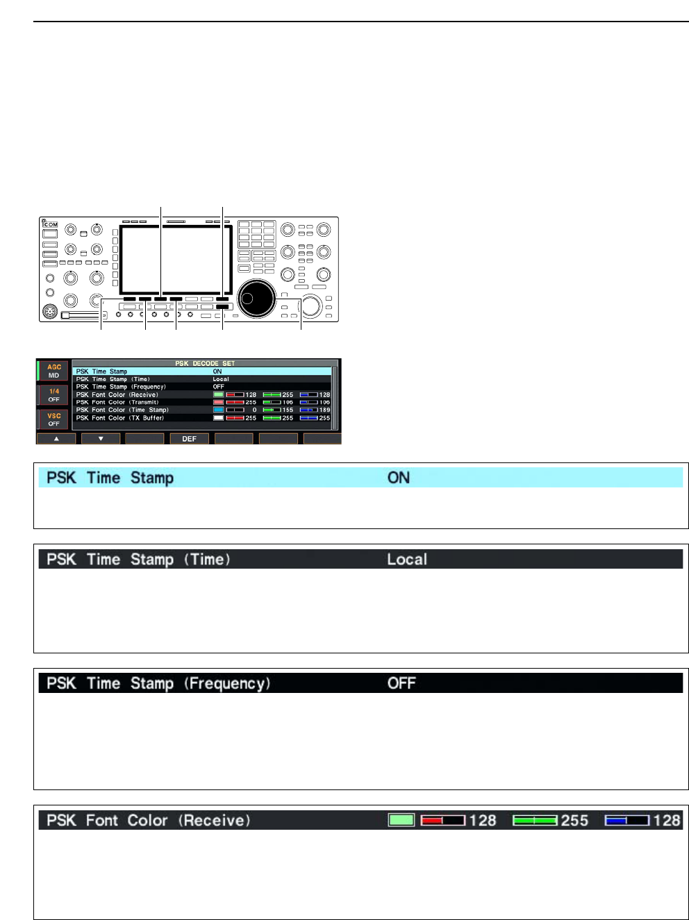
DPSK decode set mode
This set mode is used to set the decode USOS func-
tion, time stamp setting, etc.
• Setting contents
qDuring PSK mode operation, push [F-3•DECODE]
to select PSK decode screen.
wPush [F-1•<MENU2>] to select PSK decode menu
2, then push [F-6•SET] to select PSK decode set
mode.
• Push [F-7•WIDE] to toggle the screen size from normal
and wide.
ePush [F-1•Y] or [F-2•Z] to select the desired set
item.
rSet the desired condition using the main dial.
• Push [F-4•DEF] for 1 sec. to select a default condition
or value.
• Push [F-3•Ω≈] to select the set contents for some
items.
tPush [EXIT/SET] to exit from set mode.
[F-1•Y] Main dial[EXIT/SET][F-2•Z][F-4•DEF]
[F-3•Ω ≈] [F-7•WIDE]
4RECEIVE AND TRANSMIT
Turn the time stamp (date, transmission or reception
time) indication ON and OFF.
• ON : Indicates the time stamp.
• OFF : No time stamp indication.
Selects the clock indication for time stamp usage.
NOTE: The time won’t be displayed when “OFF” is
selected in “PSK Time Stamp” as above.
• Local : Selects the time that set in “Time (Now).”
• UTC* : Selects the time that set in “CLOCK2.”
*The name of choice may differ according to
“CLOCK2 Name” setting (p, 11-2). “UTC” is the
default name setting of CLOCK2.
Selects the operating frequency indication for time
stamp usage.
NOTE: The frequency won’t be displayed when
“OFF” is selected in “PSK Time Stamp” as
above.
• ON : Indicates the operating frequency.
• OFF : No operating frequency indication.
Set the text color for received characters. • The color is set in RGB format.
• Push [F-3•Ω≈] to select R (Red), G (Green) and B
(Blue), and rotate the ratio from 0 to 255 range.
• The set color is indicated in the box beside the RGB
scale.
4-27
DPSK decode set mode (continued)
4
RECEIVE AND TRANSMIT
Set the text color for transmitted characters. • The color is set in RGB format.
• Push [F-3•Ω≈] to select R (Red), G (Green) and B
(Blue), and rotate the ratio from 0 to 255 range.
• The set color is indicated in the box beside the RGB
scale.
Set the text color for time stamp indication. • The color is set in RGB format.
• Push [F-3•Ω≈] to select R (Red), G (Green) and B
(Blue), and rotate the ratio from 0 to 255 range.
• The set color is indicated in the box beside the RGB
scale.
Set the text color in the TX buffer screen. • The color is set in RGB format.
• Push [F-3•Ω≈] to select R (Red), G (Green) and B
(Blue), and rotate the ratio from 0 to 255 range.
• The set color is indicated in the box beside the RGB
scale.
4-28
DData saving
The contents of the PSK memory and received signal
can be saved into the CF memory card.
qDuring PSK decode screen indication, push
[F-1•<MENU1>] to select PSK decode menu 2.
wPush [F-5•SAVE] to select decode file save screen.
eChange the following conditions if desired.
• File name:
zPush [F-4•EDIT] to select file name edit con-
dition.
• Push [F-1• DIR/FILE] several times to select the
file name, if necessary.
xPush [ABC], [123] or [Symbol] to select the
character group, then rotate the main dial to
select the character.
• [ABC] : A to Z (capital letters); [123]: 0 to 9 (nu-
merals); [Symbol]: ! # $ % & ‘ ` ^ + – = ( ) [ ] { } _ ~
@ can be selected.
• Push [F-1•Ω] to move the cursor left, push [F-2•≈]
to move the cursor right, [F-3•DEL] delete a char-
acter and push [F-4•SPACE] to insert a space.
cPush [EXIT/SET] to set the file name.
• File format
zPush [F-5•OPTION] to enter save option
screen.
xRotate the main dial to select the saving for-
mat from Text and HTML.
• “Text” is the default setting.
• Push [F-4•DEF] for 1 sec. to select the default set-
ting.
cPush [EXIT/SET] to return to the previous in-
dication.
• Saving location
zPush [F-1•DIR/FILE] to select tree view
screen.
xSelect the desired directory or folder in the CF
memory card.
• Push [F-4•Ω≈] to select the upper directory.
• Push [F-2•Y] or [F-3•Z] to select folder in the
same directory.
• Push [F-4•Ω≈] for 1 sec. to select a folder in the
directory.
• Push [F-5•REN/DEL] to rename the folder.
• Push [F-5•REN/DEL] for 1 sec. to delete the
folder.
• Push [F-6•MAKE] for 1 sec. to mak a new folder.
(Edit the name with the same manner as the
“• File name” above.)
cPush [F-1•DIR/FILE] twice to select the file
name.
rPush [F-6•SAVE].
• After the saving is completed, return to PSK decode
menu 2 automatically.
[F-1•DIR/FILE] Main dial[EXIT/SET][F-4•EDIT]
[F-5•OPTION] [F-6•SAVE] [F-7•WIDE]
4RECEIVE AND TRANSMIT
• Decode file save screen
• Decode file save screen— file name edit
• Save option screen
✔
For your convenient!
Both of data formats, Text and HTML, are compatible
data format in a PC. The saved data can be copied to
your PC for record, etc.

4-29
■Operating AM
qPush a band key to select the desired band.
wPush [AM/FM] to select AM.
• “AM” indicator appears.
• After AM mode is selected, push [AM/FM] to toggle be-
tween AM and FM modes.
eRotate the main dial to tune the desired frequency.
• The S-meter indicates received signal strength when
signal is received.
rRotate [AF] to set audio to a comfortable listening
level.
tPush [TRANSMIT] or [PTT] (microphone) to trans-
mit.
• The TX indicator lights red.
ySpeak into the microphone at your normal voice
level.
• Adjust the microphone gain with [MIC] at this step, if
necessary.
uPush [TRANSMIT] or release [PTT] (microphone) to
return to receive.
DConvenient functions for receive
• Preamp (p. 5-9)
➥Push [P.AMP] several times to set the preamp
OFF, preamp 1 ON or preamp 2 ON.
• “P.AMP1” or “P.AMP2” appears when the preamp 1 or
preamp 2 is set to ON, respectively. (depending on
operating frequency band)
• Attenuator (p. 5-9)
➥Push [ATT] several times to set the attenuator in
6 dB steps.
• Pushing [P.AMP] for 1 sec. to set the attenuator in
3 dB steps.
• “ATT” and attenuation level appear when the attenu-
ator is set to ON.
• Noise blanker (p. 5-17)
➥Push [NB] switch to turn the noise blanker ON
and OFF, and then rotate [NB] control to adjust
the threshold level.
• Noise blanker indicator (above [NB] switch) lights
when the noise blanker is set to ON.
• Push [NB] for 1 sec. to enter noise blanker set mode.
• Noise reduction (p. 5-18)
➥Push [NR] switch to turn the noise reduction ON
and OFF.
• Rotate [NR] control to adjust the noise reduction
level.
• Noise reduction indicator (above [NR] switch) lights
when the noise reduction is set to ON.
• Twin PBT (passband tuning) (p. 5-12)
➥Rotate [TWIN PBT] controls (inner/outer).
• Push [PBT CLEAR] to clear the settings.
• Notch filter (p. 5-19)
➥Push [NOTCH] switch to turn the manual notch
function ON and OFF.
• Rotate [NOTCH] control to set the attenuating fre-
quency.
• Notch indicator (above [NOTCH] switch) lights when
either the manual notch is set to ON.
• AGC (auto gain control) (p. 5-11)
➥Push [AGC] switch several times to select
AGC FAST, AGC MID or AGC SLOW.
➥Push [AGC VR] to turn the AGC time constant
manual setting ON and OFF.
• Rotate [AGC] control to adjust the time constant.
• Auto tuning function (p. 1-9)
➥Push [AUTO TUNE] to turn the auto tuning func-
tion ON and OFF.
• The transceiver automatically tuned into the desired
signal within ±500 kHz range.
IMPORTANT!
When receiving a weak signal, or receiving a signal
with interference, the automatic tuning function may
not be tuned, or tuned into an undesired signal.
Appears
[TX] indicator
[MIC] [RX] indicator
[AM/FM][AF] Main dial
Band keys
4
RECEIVE AND TRANSMIT

4-30
DConvenient functions for transmit
• VOX (voice operated transmit) (p. 6-2)
➥Push [VOX/BK-IN] to turn the VOX function ON
and OFF.
• “VOX” appears when the VOX function is set to ON.
• Transmit quality monitor (p. 6-4)
➥Push [MONI] to turn the monitor function ON and
OFF.
• Rotate [MONI GAIN] to adjust the monitor gain.
• Monitor indicator (above [MONI] switch) lights when
the monitor function is set to ON.
• Audio tone control (p. 12-4)
➥Push [F-7•SET] then [F-1•LEVEL] to enter level
set mode. Select an item with [F-1•Y]/[F-2•Z]
then rotate the main dial to adjust the audio tone.
4RECEIVE AND TRANSMIT
4-31
■Operating FM
qPush a band key to select the desired band.
wPush [AM/FM] to select FM.
• “FM” indicator appears.
• After FM mode is selected, push [AM/FM] to toggle be-
tween FM and AM modes.
eRotate the main dial to tune the desired frequency.
• The S-meter indicates received signal strength when
signal is received.
• 10 kHz tuning step is preset for the FM mode.
rRotate [AF] to set audio to a comfortable listening
level.
tPush [TRANSMIT] or [PTT] (microphone) to trans-
mit.
• The TX indicator lights red.
ySpeak into the microphone at your normal voice
level.
• Adjust the microphone gain with [MIC] at this step, if
necessary.
uPush [TRANSMIT] or release [PTT] (microphone) to
return to receive.
DConvenient functions for receive
DConvenient functions for transmit
• VOX (voice operated transmit) (p. 6-2)
➥Push [VOX/BK-IN] to turn the VOX function ON
and OFF.
• “VOX” appears when the VOX function is set to ON.
• Transmit quality monitor (p. 6-4)
➥Push [MONI] to turn the monitor function ON and
OFF.
• Rotate [MONI GAIN] to adjust the monitor gain.
• Monitor indicator (above [MONI] switch) lights when
the monitor function is set to ON.
• Audio tone control (p. 12-4)
➥Push [F-7•SET] then [F-1•LEVEL] to enter level
set mode. Select an item with [F-1•Y]/[F-2•Z]
then rotate the main dial to adjust the audio tone.
• Preamp (p. 5-9)
➥Push [P.AMP] several times to set the preamp
OFF, preamp 1 ON or preamp 2 ON.
• “P.AMP1” or “P.AMP2” appears when the preamp 1 or
preamp 2 is set to ON, respectively. (depending on
operating frequency band)
• Auto notch filter (p. 5-19)
➥Push [NOTCH] switch to turn the auto notch func-
tion ON and OFF.
• Notch indicator (above [NOTCH] switch) lights when
either the manual notch is set to ON.
• Attenuator (p. 5-9)
➥Push [ATT] several times to set the attenuator in
6 dB steps.
• Pushing [P.AMP] for 1 sec. to set the attenuator in
3 dB steps.
• “ATT” and attenuation level appear when the attenu-
ator is set to ON.
Appears
[TX] indicator
[MIC] [RX] indicator
[AM/FM][AF] Main dial
Band keys
4
RECEIVE AND TRANSMIT
4-32
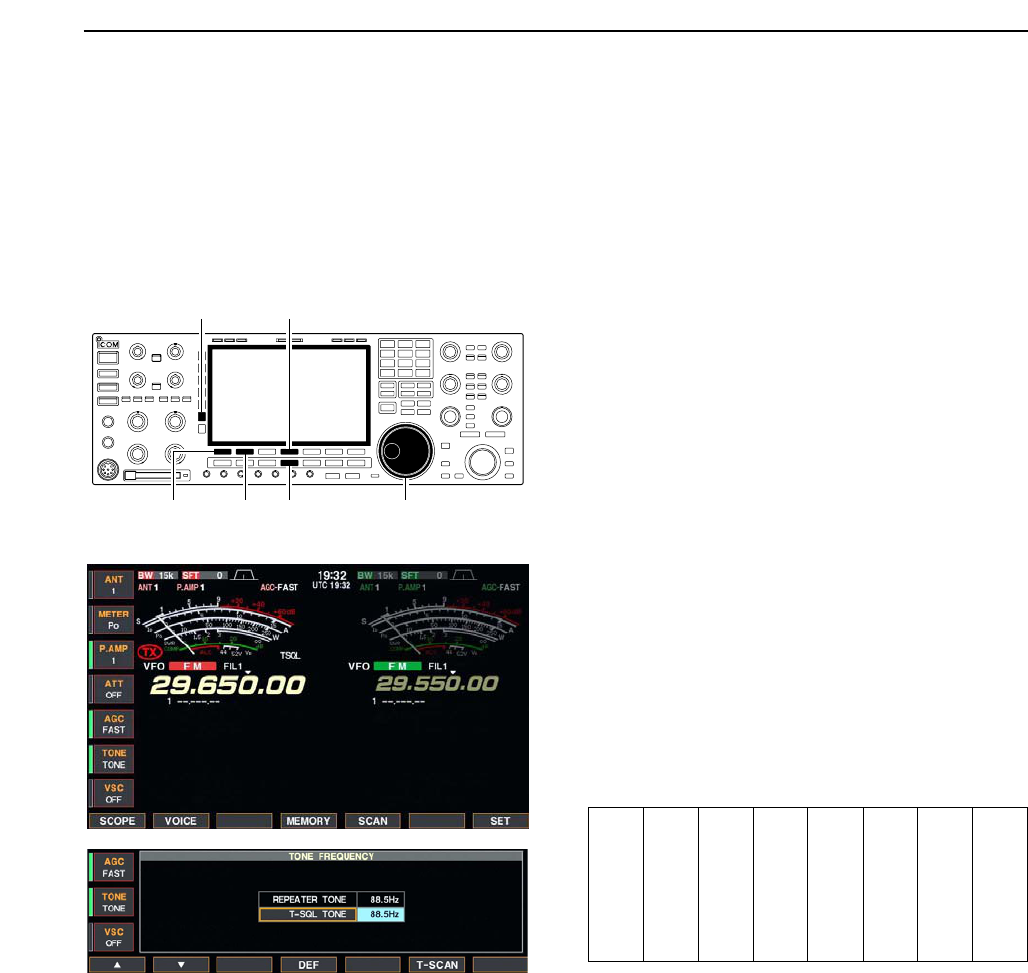
■Repeater operation
A repeater amplifies received signals and retransmits
them at a different frequency. When using a repeater,
the transmit frequency is shifted from the receive fre-
quency by an offset frequency. A repeater can be ac-
cessed using split frequency operation with the shift
frequency set to the repeater’s offset frequency.
For accessing a repeater which requires a repeater
tone, set the repeater tone frequency in tone fre-
quency set mode as described below.
qSet the offset frequencies (HF, 50 MHz) and turn
ON the quick split function in miscellaneous (others)
set mode in advance. (p. 12-14)
wPush [V/M] to select VFO mode.
ePush the desired band key.
rPush [AM/FM] several times to select FM mode.
tSet the receive frequency (repeater output fre-
quency).
yPush [SPLIT] for 1 sec. to start repeater operation.
• Repeater tone is turned ON automatically.
• [SPLIT] indicator lights and “ ” appears on the
LCD.
• Shifted transmit frequency and “TX” appear in the sub
band.
• The transmit frequency can be monitored while pushing
[XFC] or using dualwatch.
uPush and hold [PTT] to transmit; release [PTT] to
receive.
iTo return to simplex, push [SPLIT] momentarily.
DRepeater tone frequency setting
Some repeaters require subaudible tones to be ac-
cessed. Subaudible tones are superimposed over your
normal signal and must be set in advance. The trans-
ceiver has 50 tones from 67.0 Hz to 254.1 Hz.
qSelect FM mode.
wPush [TONE] for 1 sec. to tone frequency set mode.
ePush [F-1•Y] or [F-2•Z] to select REPEATER
TONE item.
rRotate the main dial to select the desired repeater
tone frequency.
• Push [F-4•DEF] for 1 sec. to select the default setting.
tPush [EXIT/SET] to return to the previous indica-
tion.
• Available tone frequencies (unit: Hz)
[AM/FM][F-1•Y] [F-2•Z] Main dial
[F-4•DEF][TONE]
[V/M]
[AM/FM] [XFC] [SPLIT]Main dial
Band keys[SPLIT] indicator
4RECEIVE AND TRANSMIT
67.0
69.3
71.9
74.4
77.0
79.7
82.5
085.4
088.5
091.5
094.8
097.4
100.0
103.5
107.2
110.9
114.8
118.8
123.0
127.3
131.8
136.5
141.3
146.2
151.4
156.7
159.8
162.2
165.5
167.9
171.3
173.8
177.3
179.9
183.5
186.2
189.9
192.8
196.6
199.5
203.5
206.5
210.7
218.1
225.7
229.1
233.6
241.8
250.3
254.1
4-33
■Tone squelch operation
The tone squelch opens only when receiving a signal
containing a matching subaudible tone. You can
silently wait for calls from group members using the
same tone.
qSet the desired frequency band and select FM
mode.
wPush [TONE] to turn the tone squelch function ON.
• “TSQL” appears
ePush [TONE] for 1 sec. to tone frequency set mode.
rPush [F-1•Y] or [F-2•Z] to select T-SQL TONE
item.
tRotate the main dial to select the desired tone
squelch frequency.
• Push [F-4•DEF] for 1 sec. to select the default setting.
yPush [EXIT/SET] to return to the previous indica-
tion.
uWhen the received signal includes a matching tone,
squelch opens and the signal can be heard.
• When the received signal’s tone does not match, tone
squelch does not open, however, the S-indicator shows
signal strength.
• To open the squelch manually, push [XFC].
iOperate the transceiver in the normal way.
oTo cancel the tone squelch, push [TONE] to clear
“TSQL.”
• Available tone frequencies (unit: Hz)
[AM/FM][F-1•Y] [F-2•Z] Main dial
[F-4•DEF][TONE]
4
RECEIVE AND TRANSMIT
67.0
69.3
71.9
74.4
77.0
79.7
82.5
085.4
088.5
091.5
094.8
097.4
100.0
103.5
107.2
110.9
114.8
118.8
123.0
127.3
131.8
136.5
141.3
146.2
151.4
156.7
159.8
162.2
165.5
167.9
171.3
173.8
177.3
179.9
183.5
186.2
189.9
192.8
196.6
199.5
203.5
206.5
210.7
218.1
225.7
229.1
233.6
241.8
250.3
254.1
4-34
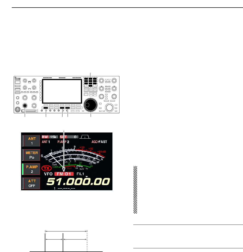
■Data mode (AFSK) operation
When operating AMTOR or PACKET with your TNC
and/or PC software, consult the manual that comes
with the TNC and/or the software.
qConnect a PC and TNC to the transceiver. (p. 2-8)
wPush a band key to select the desired band.
ePush [SSB] or [AM/FM] to select the desired oper-
ating mode.
rPush [DATA] to turn data mode ON.
• One of “-D1,” “-D2” or “-D3” is additionally appears.
• During data mode selection, pushing [DATA] for 1 sec.
to select data mode 1 (D1), 2 (D2) and 3 (D3) in se-
quence.
tRotate the main dial to tune into the desired signal
and decoded correctly.
• Also use the tuning indicator of the TNC or software.
• During SSB data mode, 1⁄4tuning function can be used
for critical tuning.
yOperate the PC (software) or TNC to transmit.
• When operating in SSB data mode, adjust the TNC out-
put level so that the ALC meter reading doesn’t go out-
side the ALC zone.
NOTE: When SSB data mode is selected, the audio
input from the [ACC1] (pin 6) is used for transmis-
sion instead of [MIC]’s.
The fixed condition is used for SSB data transmis-
sion as follow.
• [COMP] : OFF
• Tx bandwidth : MID
• Tx Tone (Bass) : 0
• Tx Tone (Trebles): 0
✔
For your information
Carrier point frequency is displayed when SSB data
mode is selected.
See the diagram left for the tone-pair example.
200 Hz 2125 Hz
2325 Hz
Carrier point
(displayed frequency)
Appears
[AM/FM][SSB][AF] [DATA] Main dial
Band keys
4RECEIVE AND TRANSMIT