ICOM orporated 259000 Amateur HF Scanning Transceiver User Manual IC 7800 Eng
ICOM Incorporated Amateur HF Scanning Transceiver IC 7800 Eng
Contents
- 1. Users Manual Part 1
- 2. Users Manual Part 2
- 3. Users Manual Part 3
- 4. Users Manual Part 4
- 5. Users Manual Part 5
Users Manual Part 4

8-1
MEMORY OPERATION Section 8
■Memory channels ……………………………………………………… 8-2
■Memory channel selection …………………………………………… 8-2
DUsing the [Y]/[Z] keys ……………………………………………… 8-2
DUsing the keypad …………………………………………………… 8-2
■Memory list screen ……………………………………………………… 8-3
DSelecting a memory channel using the memory list screen …… 8-3
DConfirming programmed memory channels ……………………… 8-3
■Memory channel programming ……………………………………… 8-4
DProgramming in VFO mode ………………………………………… 8-4
DProgramming in memory mode …………………………………… 8-4
■Frequency transferring ………………………………………………… 8-5
DTransferring in VFO mode ………………………………………… 8-5
DTransferring in memory mode ……………………………………… 8-5
■Memory names ………………………………………………………… 8-6
DEditing (programming) memory names …………………………… 8-6
■Memory clearing ………………………………………………………… 8-6
■Memo pads ……………………………………………………………… 8-7
DWriting frequencies and operating modes into memo pads …… 8-7
DCalling up a frequency from a memo pad ………………………… 8-7
8-2
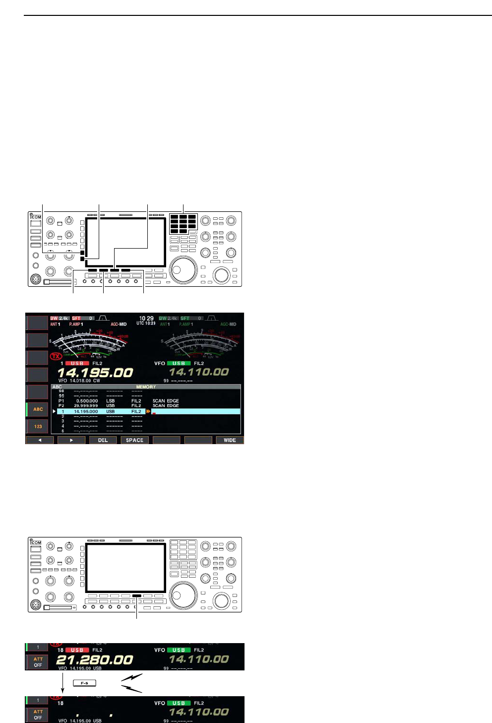
■Memory channels
The transceiver has 101 memory channels. The mem-
ory mode is very useful for quickly changing to often-
used frequencies.
All 101 memory channels are tuneable which means
the programmed frequency can be tuned temporarily
with the main dial, etc. in memory mode.
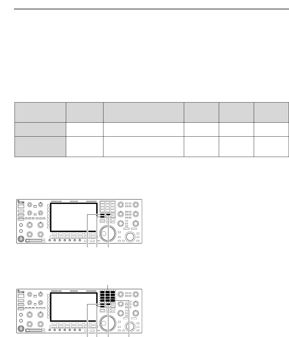
■Memory channel selection
DUsing the [Y]/[Z] keys
qPush [V/M] to select memory mode.
wPush [Y]/[Z] several times to select the desired
memory channel.
• Push and hold [Y]/[Z] for continuous selection.
• [UP] and [DN] on the microphone can also be used.
eTo return to VFO mode, push [V/M] again.
DUsing the keypad
qPush [V/M] to select memory mode.
wPush [F-INP•ENT].
ePush the desired memory channel number using the
keypad.
• Enter 100 or 101 to select scan edge channel P1 or P2,
respectively.
rPush [Y] or [Z] to select the desired memory chan-
nel.
[EXAMPLE]
To select the memory channel 3;
- Push [F-INP•ENT], [7•3], then push [Y] or [Z].
To select the memory channel 12;
- Push [F-INP•ENT], [1.8•1], [3.5•2], then push [Y] or
[Z].
To select the scan edge channel P1;
- Push [F-INP•ENT], [1.8•1], [50•0], [50•0], then push
[Y] or [Z].
To select the scan edge channel P2;
- Push [F-INP•ENT], [1.8•1], [50•0], [1.8•1], then push
[Y] or [Z].
[Y] [Z] [V/M]
Keypad
[F-INP•ENT]
[Y] [Z] [V/M]
8MEMORY OPERATION
MEMORY MEMORY TRANSFER OVER-
CHANNEL CHANNEL CAPABILITY TO VFO WRITING CLEAR
NUMBER
Regular memory 1–99 One frequency and one mode Yes Yes Yes
channels in each memory channel.
Scan edge
One frequency and one mode in
memory P1, P2 each memory channel as scan Yes Yes No
channels edges for programmed scan.
8-3
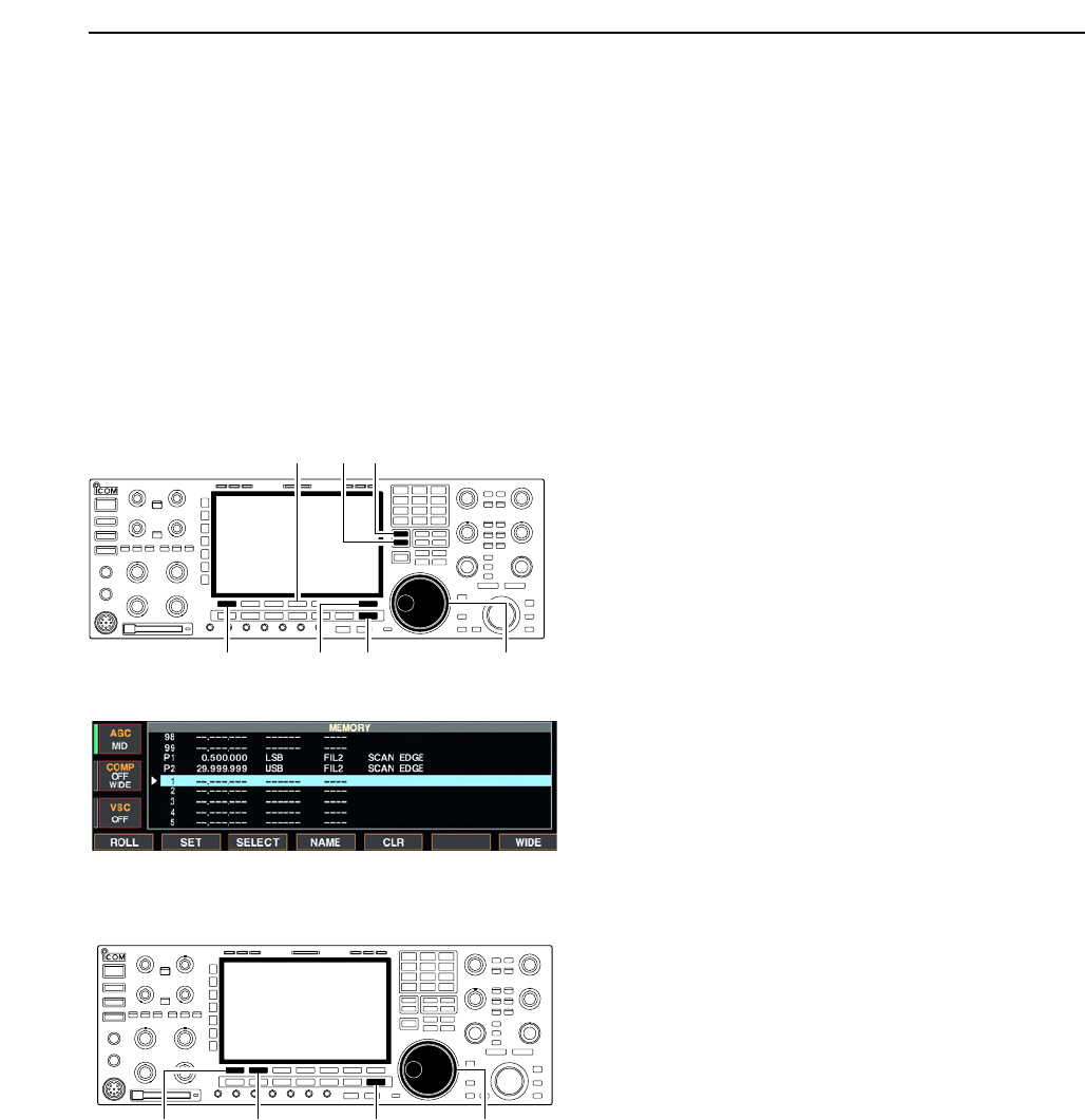
■Memory list screen
The memory list screen simultaneously shows 9 mem-
ory channels and their programmed contents. 15 mem-
ory channels can be displayed in the wide memory list
screen.
You can select a desired memory channel from mem-
ory list screen.
DSelecting a memory channel using the memory list screen
qPush [EXIT/SET] several times to close a multi-func-
tion screen, if necessary.
wPush [F-4•MEMORY] to select memory list screen.
• [F-7•WIDE] switches the standard and wide screens.
eWhile pushing [F-1•ROLL], rotate the main dial to
select the desired memory channel.
•[Y] and [Z] can also be used.
rPush [EXIT/SET] to exit memory list screen.
• Memory list screen
DConfirming programmed memory channels
qSelect memory list screen as described above.
wWhile pushing [F-1•ROLL], rotate the main dial to
scroll the screen.
ePush [F-2•SET] to select the highlighted memory
channel, if desired.
•“≈” appears beside the selected memory channel num-
ber in the memory list screen and the selected memory
channel contents are displayed below the frequency
readout.
rPush [EXIT/SET] to exit memory list screen.
Main dial[F-1•ROLL] [F-2•SET] [EXIT/SET]
[Y][Z]
Main dial[F-1•ROLL]
[F-4•MEMORY]
[EXIT/SET][F-7•WIDE]
8
MEMORY OPERATION
8-4
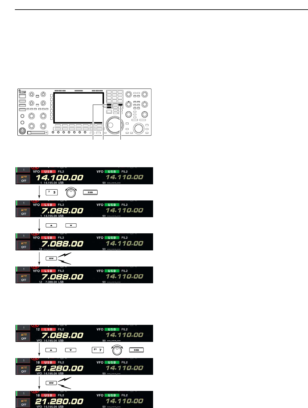
■Memory channel programming
Memory channel programming can be preformed ei-
ther in VFO mode or in memory mode.
DProgramming in VFO mode
qSet the desired frequency, operating mode and fil-
ter width in VFO mode.
wPush [Y]/[Z] several times to select the desired
memory channel.
• Memory list screen is convenient for selecting the de-
sired channel.
• Memory channel contents appear in the memory chan-
nel readout (below the frequency readout).
• “--.---.--” appears if the selected memory channel is a
blank channel (and does not have contents).
ePush [MW] for 1 sec. to program the displayed fre-
quency and operating mode into the memory chan-
nel.
DProgramming in memory mode
qSelect the desired memory channel with [Y]/[Z] in
memory mode.
• Memory channel contents appear in the memory chan-
nel readout (below the frequency readout).
• “--.---.--” appears if the selected memory channel is a
blank channel (and does not have contents).
wSet the desired frequency and operating mode in
memory mode.
• To program a blank channel, use direct frequency entry
with the keypad or memo pads, etc.
ePush [MW] for 1 sec. to program the displayed fre-
quency and operating mode into the memory chan-
nel.
[Y] [Z] [MW]
8MEMORY OPERATION
or
Push for 1 sec.
Beep
Beep
Beep
[EXAMPLE]: Programming 7.088 MHz/LSB into memory
channel 12.
or then
Push for 1 sec.
Beep
Beep
Beep
[EXAMPLE]: Programming 21.280 MHz/USB into memory
channel 18.
8-5
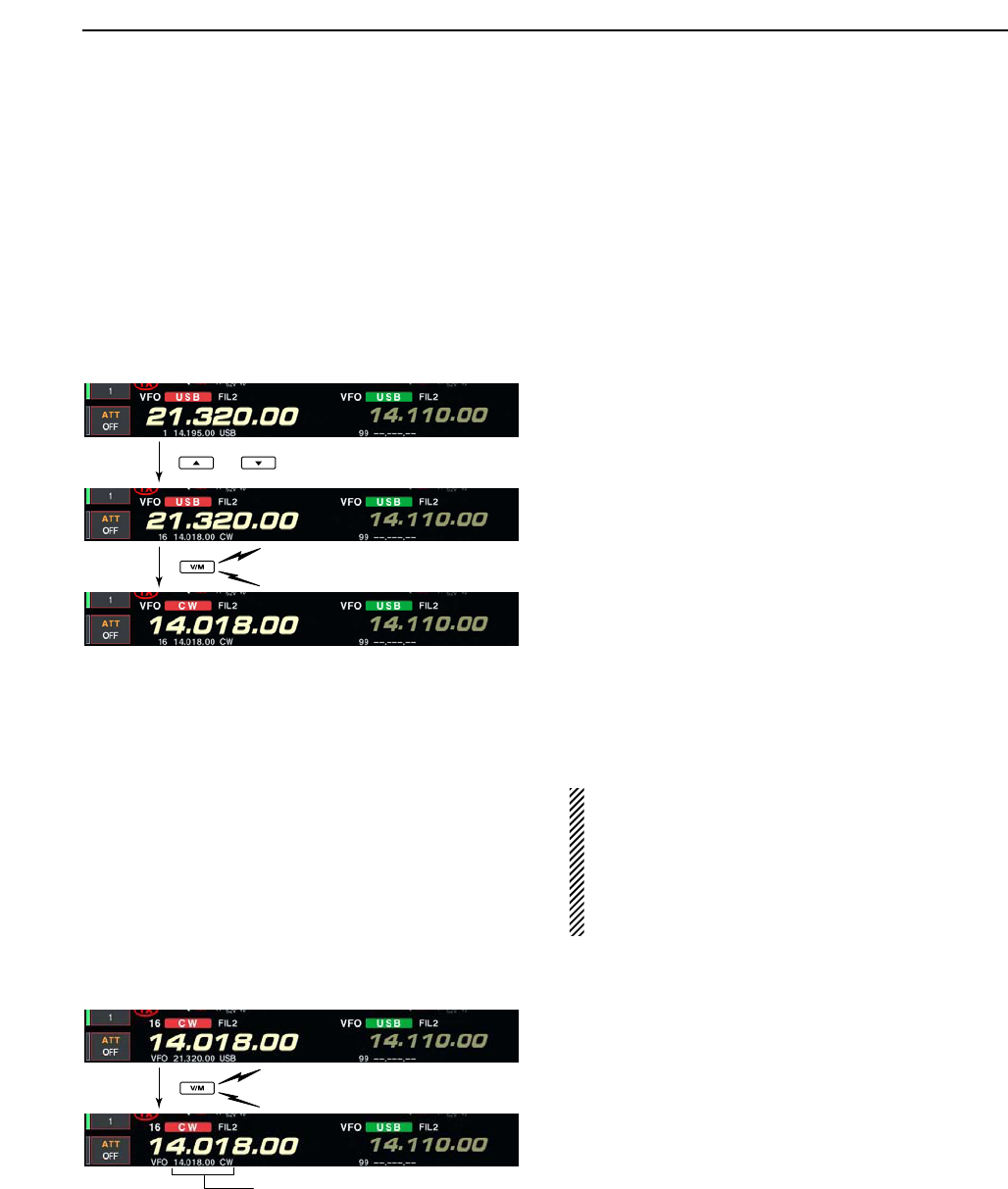
■Frequency transferring
The frequency and operating mode in a memory chan-
nel can be transferred to the VFO.
Frequency transferring can be performed in either VFO
mode or memory mode.
DTransferring in VFO mode
This is useful for transferring programmed contents to
VFO.
qSelect VFO mode with [V/M].
wSelect the memory channel to be transferred with
[Y]/[Z].
• Memory list screen is convenient for selecting the de-
sired channel.
• Memory channel contents appear in the memory chan-
nel readout (below the frequency readout).
• “--.---.--” appears if the selected memory channel is a
blank channel. In this case transferring is impossible.
ePush [V/M] for 1 sec. to transfer the frequency and
operating mode.
• Transferred frequency and operating mode appear on
the frequency readout.
DTransferring in memory mode
This is useful for transferring frequency and operating
mode while operating in memory mode.
When you have changed the frequency or operat-
ing mode in the selected memory channel:
•Displayed frequency, mode and filter setting are
transferred.
•Programmed frequency and mode in the memory
channel are not transferred, and they remain in the
memory channel.
qSelect the memory channel to be transferred with
[Y]/[Z] in memory mode.
• And, set the frequency or operating mode if required.
wPush [V/M] for 1 sec. to transfer the frequency and
operating mode.
• Displayed frequency and operating mode are transferred
to the VFO.
eTo return to VFO mode, push [V/M] momentarily.
8
MEMORY OPERATION
TRANSFERRING EXAMPLE IN VFO MODE
Operating frequency : 21.320 MHz/USB (VFO)
Contents of M-ch 16 : 14.018 MHz/CW
TRANSFERRING EXAMPLE IN MEMORY MODE
Operating frequency : 21.320 MHz/USB (M-ch 16)
Contents of M-ch 16 : 14.018 MHz/CW
or
Push for 1 sec.
Beep
Beep
Beep
Push for 1 sec.
Beep
Beep
Beep
Programmed contents appear.
8-6
■Memory names
All memory channels (including scan edges) can be
tagged with alphanumeric names of up to 10 charac-
ters each.
Capital letters, small letters, numerals, some symbols
(! # $ % & ¥ ? " ’ ` ^ + – ✱/ . , : ; = < > ( ) [ ] { } | _ ~@)
and spaces can be used.
DEditing (programming) memory names
qPush [EXIT/SET] several times to close a multi-func-
tion screen, if necessary.
wPush [F-4•MEMORY] to select memory list screen.
eSelect the desired memory channel.
rPush [F-4•NAME] to edit memory channel name.
• A cursor appears and blinks.
• Memory channel names of blank channels cannot be
edited.
tInput the desired character by rotating the main dial
or by pushing the band key for number input.
• Push [ABC] or [abc] to toggle capital and small letters.
• Push [123] or [Symbol] to toggle numerals and symbols.
• Push [F-1•Ω] or [F-2•≈] for cursor movement.
• Push [F-3•DEL] to delete the selected character.
• Push [F-4•SPACE] to input a space.
• Pushing the transceiver’s keypad, [0]–[9], can also enter
numerals.
yPush [EXIT/SET] to input and set the name.
• The cursor disappears.
uRepeat steps eto yto program another memory
channel’s name, if desired.
iPush [EXIT/SET] to exit memory list screen.
■Memory clearing
Any unnecessary memory channels can be cleared.
The cleared memory channels become blank chan-
nels.
qSelect memory mode with [V/M].
wPush [F-4•MEMORY] to select memory list screen.
eSelect the desired memory channel with [Y]/[Z].
rPush [F-5•CLR] for 1 sec. to clear the contents.
• The programmed frequency and operating mode disap-
pear.
tTo clear other memory channels, repeat steps e
and r.
Push for 1 sec.
Beep
Beep
Beep
(CLR)
[F-5•CLR]
[F-1•Ω] [F-2•≈] [F-4•SPACE]
[F-3•DEL] Keypad[ABC]/[abc] [123]/[Symbol]
8MEMORY OPERATION
8-7
■Memo pads
The transceiver has a memo pad function to store fre-
quency and operating mode for easy write and recall.
The memo pads are separate from memory channels.
The default number of memo pads is 5, however, this
can be increased to 10 in set mode if desired. (p. 12-
16)
Memo pads are convenient when you want to memo-
rize a frequency and operating mode temporarily, such
as when you find a DX station in a pile-up, or when a
desired station is busy for a long time and you want to
temporarily search for other stations.
Use the transceiver’s memo pads instead of relying on
hastily scribbled notes that are easily misplaced.
DWriting frequencies and operating modes into memo pads
You can simply write the accessed readout frequency
and operating mode by pushing [MP-W].
When you write a 6th frequency and operating mode,
the oldest written frequency and operating mode are
automatically erased to make room for the new set-
tings.
Each memo pad must have its own unique combi-
nation of frequency and operating mode; memo
pads having identical settings cannot be written.
DCalling up a frequency from a memo pad
You can simply call up the desired frequency and op-
erating mode of a memo pad by pushing [MP-R] sev-
eral times.
• Both VFO and memory modes can be used.
• The frequency and operating mode are called up, starting
from the most recently written.
When you call up a frequency and an operating mode
from memo pads with [MP-R], the previously displayed
frequency and operating mode are automatically
stored in a temporary pad. The frequency and operat-
ing mode in the temporary pad can be recalled by
pushing [MP-R] several times.
• You may think there are 6 memo pads because 6 different
frequencies (5 are in memo pads and 1 is in the temporary
pad) are called up by [MP-R].
If you change the frequency or operating mode
called up from a memo pad with the main dial, etc.,
the frequency and operating mode in the temporary
pad are erased.
Newest
MEMO PADS
Oldest
Newest
Erased
Oldest
In this example, 21.276 MHz (LSB) will be erased
when 7.067 MHz (LSB) is written.
[MP-R][MP-W]
8
MEMORY OPERATION

9-1
SCANS Section 9
■Scan types ……………………………………………………………… 9-2
■Preparation ……………………………………………………………… 9-2
■Voice squelch control function ………………………………………… 9-3
■Scan set mode ………………………………………………………… 9-3
■Programmed scan operation ………………………………………… 9-4
■∂F scan operation ……………………………………………………… 9-4
■Fine programmed scan/∂F scan ……………………………………… 9-5
■Memory scan operation ………………………………………………… 9-6
■Select memory scan operation ……………………………………… 9-6
■Setting select memory channels ……………………………………… 9-7
DSetting in scan screen ……………………………………………… 9-7
DSetting in memory list screen ……………………………………… 9-7
DErasing the select scan setting …………………………………… 9-7
■Tone scan ……………………………………………………………… 9-8
9-2
■Scan types
• The scan function can be used on the main read-
out only.
• You can operate a scan while operating on a fre-
quency using the dualwatch or split functions.
PROGRAMMED SCAN
Repeatedly scans between two scan edge frequencies
(scan edge memory channels P1 and P2).
This scan operates in VFO mode.
SELECT MEMORY SCAN
Repeatedly scans all or one of 3 select memory channels.
∂F SCAN
Repeatedly scans within ∂F span area.
This scan operates in memory mode.This scan operates in memory mode.
This scan operates in both VFO and memory modes.
Scan
Scan edge
P1 or P2
Scan edge
P2 or P1
Jump
MEMORY SCAN
Repeatedly scans all programmed memory channels.
Mch 1
★1
Mch 5
★1
Mch 2
★2
Mch 3
★1Mch 4
Mch 6
★3
Mch 7
★1
Mch 99
★1
Mch 1
★1
Mch 5
★1
Mch 2
★2
Mch 3
★1Mch 4
Mch 6
★3
Mch 7
★1
Mch 99
★1
Blank channel Blank channel
ScanScan
–∂F frequency +∂F frequency
Start frequency
Jump
*“★1,” “★2” and “★3” show that the channel
is specified as the select memory.
*“★1,” “★2” and “★3” show that the channel
is specified as the select memory.
9SCANS
■Preparation
• Channels
For programmed scan:
Program scan edge frequencies into scan edge mem-
ory channels P1 and P2.
For
∂
F scan:
Set the ∂F span (∂F scan range) in the scan screen.
For memory scan:
Program 2 or more memory channels except scan
edge memory channels.
For select memory scan:
Designate 2 or more memory channels as select mem-
ory channels. To designate the channel as a select
memory channel, choose a memory channel, then
push [F-3•SELECT] in the scan screen (memory
mode) or in the memory list screen.
• Scan resume ON/OFF
You can select the scan to resume or cancel when de-
tecting a signal, in set mode. Scan resume ON/OFF
must be set before operating a scan. See p. 9-3 for
ON/OFF setting and scan resume condition details.
• Scan speed
Scan speed can be selected from 2 levels, high or low,
in scan set mode. See p. 9-3 for details.
• Squelch condition
SQUELCH
CLOSED
SQUELCH
OPEN
Scan stops when detecting a signal.
If you set scan resume ON in set mode, the
scan pauses for 10 sec. when detecting a
signal, then resumes. When a signal disap-
pears while scan is paused, scan resumes
2 sec. later.
The scan continues
until it is stopped
manually, and does
not pause even if it
detects signals.
Scan pauses on
each channel when
the scan resume is
ON; not applicable
when OFF.
SCAN PROGRAMMED
STARTS SCAN MEMORY SCAN
WITH
9-3
■Voice squelch control function
This function is useful when you don’t want unmodu-
lated signals pausing or cancelling a scan. When the
voice squelch control function is activated, the receiver
checks received signals for voice components.
If a receiver signal includes voice components, and the
tone of the voice components changes within 1 sec.,
scan pauses (or stops). If the received signal includes
no voice components or the tone of the voice compo-
nents does not change within 1 sec., scan resumes.
➥While a phone mode (SSB, AM or FM) is selected,
push [VSC] to switch the VSC (Voice Squelch Con-
trol) function ON and OFF.
• “VSC” appears when the function is activated.
• The VSC function activates for any scan.
• The VSC function resumes the scan on unmodu-
lated signals, regardless of whether the scan re-
sume condition is set to ON or OFF.
■Scan set mode
When the squelch is open, scan continues until it is
stopped manually— it does not pause on detected sig-
nals. When squelch is closed, scan stops when de-
tecting a signal, then resumes according to the scan
resume condition. Scan speed and the scan resume
condition can be set using the scan set mode.
qPush [F-5•SCAN] to select scan screen.
wPush [F-7•SET] to select scan set mode.
ePush [F-1•Y] or [F-2•Z] to select the desired item.
rRotate the main dial to select the desired condition.
• Push [F-4•DEF] for 1 sec. to select the default setting.
tPush [EXIT/SET] to return to scan menu.
[F-2•Z][F-1•Y][EXIT/SET] Main dial[F-4•DEF]
[VSC]
9
SCANS
Select the desired scan speed from high and low. • HIGH : scan is faster
• LOW : scan is slower
Set the scan resume function ON and OFF. • ON : When detecting a signal, scan pauses for
10 sec., then resumes. When a signal disap-
pears, scan resumes 2 sec. later.
• OFF : When detecting a signal, cancels scanning.
9-4
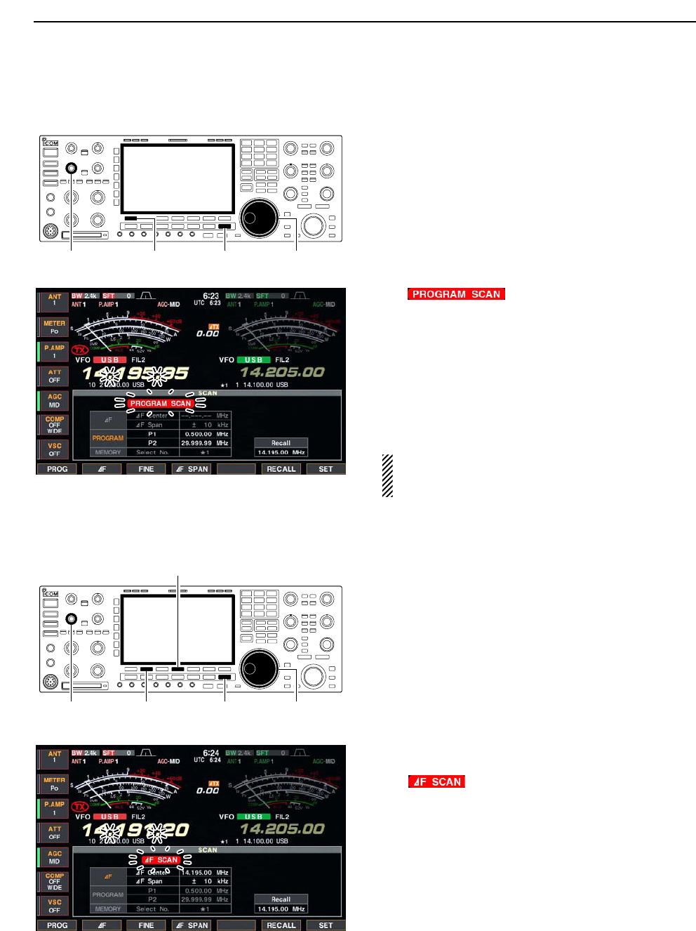
■Programmed scan operation
qPush [EXIT/SET] several times to close a multi-func-
tion screen, if necessary.
wSelect VFO mode.
eSelect the desired operating mode.
• The operating mode can also be changed while scan-
ning.
rPush [F-5•SCAN] to select the scan screen.
tSet the main band’s [SQL] open or closed.
• See page 9-2 for squelch condition.
yPush [F-1•PROG] to start the programmed scan.
• “ ” and decimal points blink while
scanning.
uWhen the scan detects a signal, the scan stops,
pauses or ignores it depending on the resume set-
ting and the squelch condition.
iTo cancel the scan, push [F-1•PROG].
• Rotating the main dial also cancels the scan.
oPush [F-6•RECALL] for 1 sec. to recall the fre-
quency that is set before starting the scan, if de-
sired.
If the same frequencies are programmed into the
scan edge memory channel P1 and P2, pro-
grammed scan does not start.
■∂F scan operation
qPush [EXIT/SET] several times to close a multi-func-
tion screen, if necessary.
wSelect VFO mode or a memory channel.
eSelect the desired operating mode.
• The operating mode can also be changed while scan-
ning.
rPush [F-5•SCAN] to select the scan screen.
tSet the main band’s [SQL] open or closed.
• See page 9-2 for squelch condition.
ySet the ∂F span by pushing [F-4•∂F SPAN].
• ±5 kHz, ±10 kHz, ±20 kHz, ±50 kHz, ±100 kHz,
±500 kHz and ±1000 kHz are selectable.
uSet center frequency of the ∂F span.
iPush [F-2•∂F] to start the ∂F scan.
• “ ” and decimal points blink while scanning.
oWhen the scan detects a signal, the scan stops,
pauses or ignores it depending on the resume set-
ting and the squelch condition.
!0 To cancel the scan, push [F-2•∂F].
• Rotating the main dial also cancels the scan.
!1 Push [F-6•RECALL] for 1 sec. to recall the fre-
quency that is set before starting the scan, if de-
sired.
[SQL] for main [F-2•∂F]
[F-4•∂F SPAN]
[EXIT/SET] Main dial
[SQL] for main [F-1•PROG] [EXIT/SET] Main dial
9SCANS
9-5
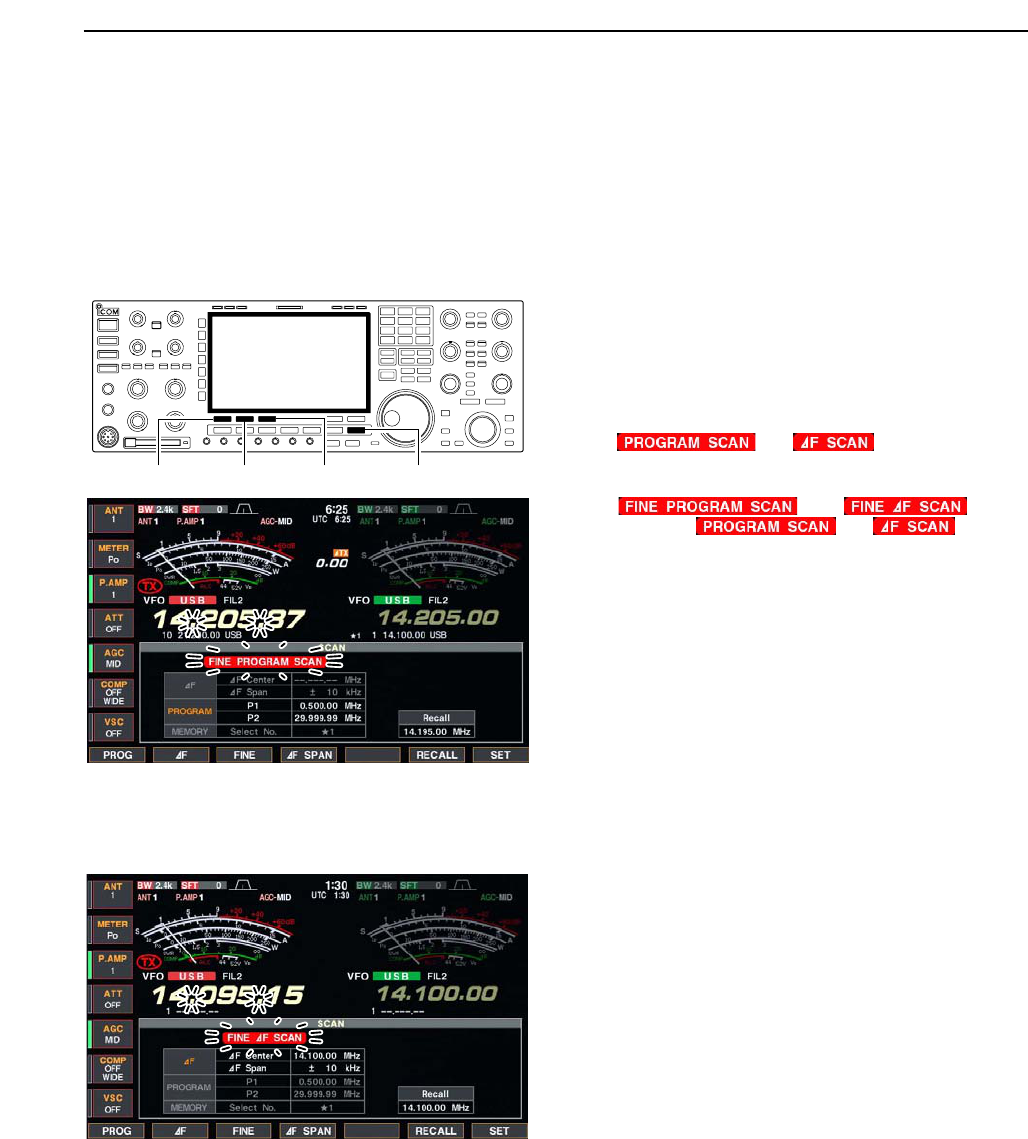
■Fine programmed scan/fine ∂F scan
Fine scan functions as programmed or ∂F scan, but
scan speed decreases when the squelch opens but
does not stop. The scanning tuning step shifts from
50 Hz to 10 Hz while the squelch opens.
qPush [EXIT/SET] several times to close a multi-func-
tion screen, if necessary.
wPush [F-5•SCAN] to select the scan screen.
eSet for programmed scan or ∂F scan as described
on previous page.
rPush [F-1•PROG] or [F-2•∂F] to start a scan.
• “ ” or “ ” and decimal points
blink while scanning.
tPush [F-3•FINE] to start a fine scan.
• “ ” or “ ” blinks
instead of “ ” or “ ,” respec-
tively.
yWhen the scan detects a signal, the scan speed de-
creases but does not stop.
uPush [F-1•PROG] or [F-2•∂F] to stop the scan; push
[F-3•FINE] to cancel the fine scan.
• Rotating the main dial also cancels the scan.
iPush [F-6•RECALL] for 1 sec. to recall the fre-
quency that is set before starting the scan, if de-
sired.
[F-2•∂F][F-1•PROG] [F-3•FINE] [EXIT/SET]
9
SCANS
9-6
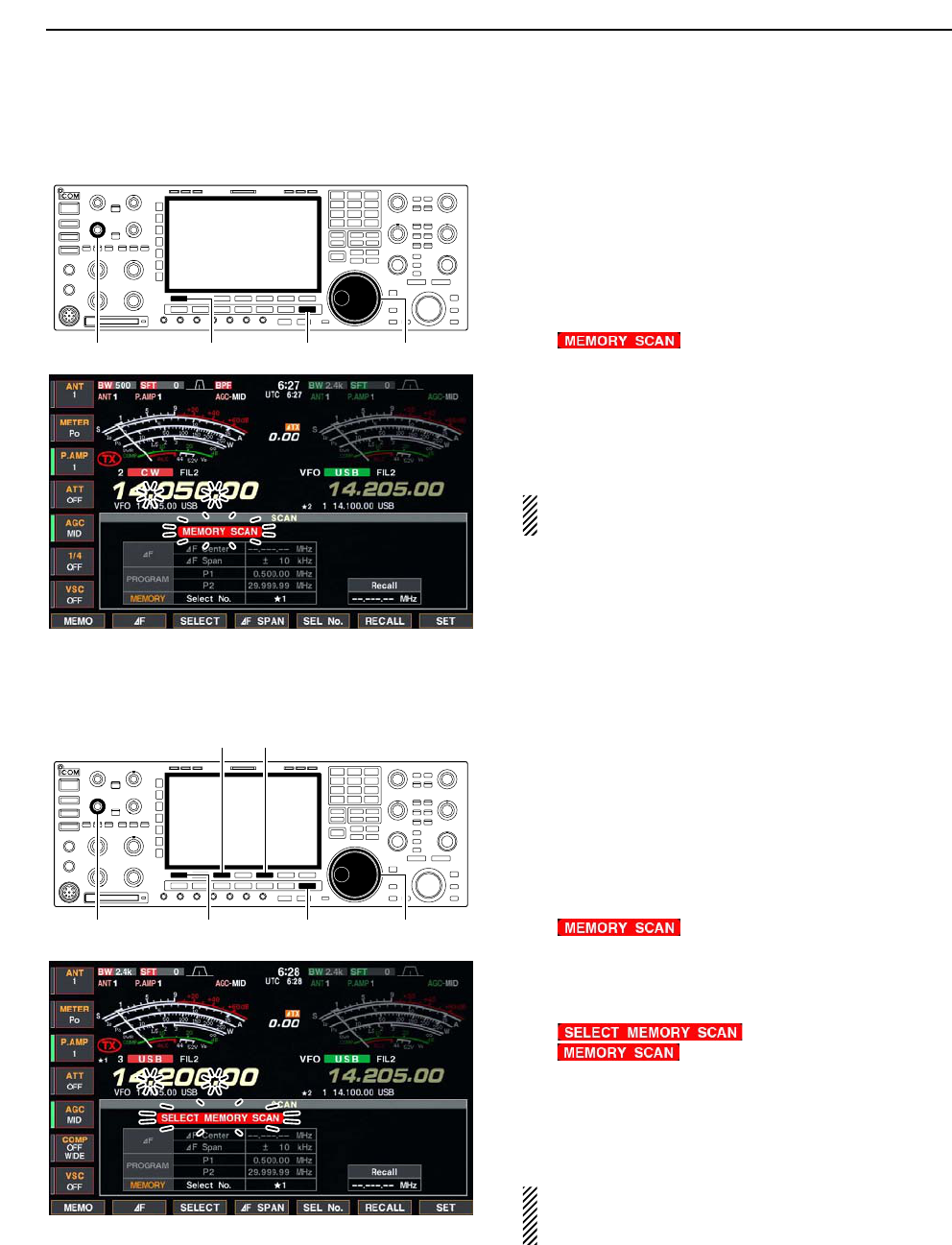
■Memory scan operation
qPush [EXIT/SET] several times to close a multi-func-
tion screen, if necessary.
wSelect memory mode.
ePush [F-5•SCAN] to select the scan screen.
rSet the main band’s [SQL] open or closed.
• See page 9-2 for squelch condition.
tPush [F-1•MEMO] to start the memory scan.
• “ ” and decimal points blink while scan-
ning.
yWhen the scan detects a signal, the scan stops,
pauses or ignores it depending on the resume set-
ting and the squelch condition.
uTo cancel the scan, push [F-1•MEMO].
• Rotating the main dial also cancels the scan.
2 or more memory channels must be programmed
for memory scan to start.
■Select memory scan operation
qPush [EXIT/SET] several times to close a multi-func-
tion screen, if necessary.
wSelect memory mode.
ePush [F-5•SCAN] to select the scan screen.
rSet the main band’s [SQL] open or closed.
• See page 9-2 for squelch condition.
tPush [F-5•SEL No.] several times to select the se-
lect scan number from ★1, ★2, ★3 and ★1/★2/★3.
yPush [F-1•MEMO] to start the memory scan.
• “ ” and decimal points blink while scan-
ning.
uPush [F-3•SELECT] to start select memory scan;
push [F-3•SELECT] again to return to memory scan,
if desired.
• “ ” blinks instead of
“ ” during select memory scan.
iWhen the scan detects a signal, the scan stops,
pauses or ignores it depending on the resume set-
ting and the squelch condition.
oTo cancel the scan, push [F-1•MEMO].
• Rotating the main dial also cancels the scan.
2 or more memory channels must be designated as
select memory channels, as well as the same select
scan number, for select memory scan to start.
[SQL] for main [F-1•MEMO]
[F-3•SELECT] [F-5•SEL No.]
[EXIT/SET] Main dial
[SQL] for main [F-1•MEMO] [EXIT/SET] Main dial
9SCANS
9-7
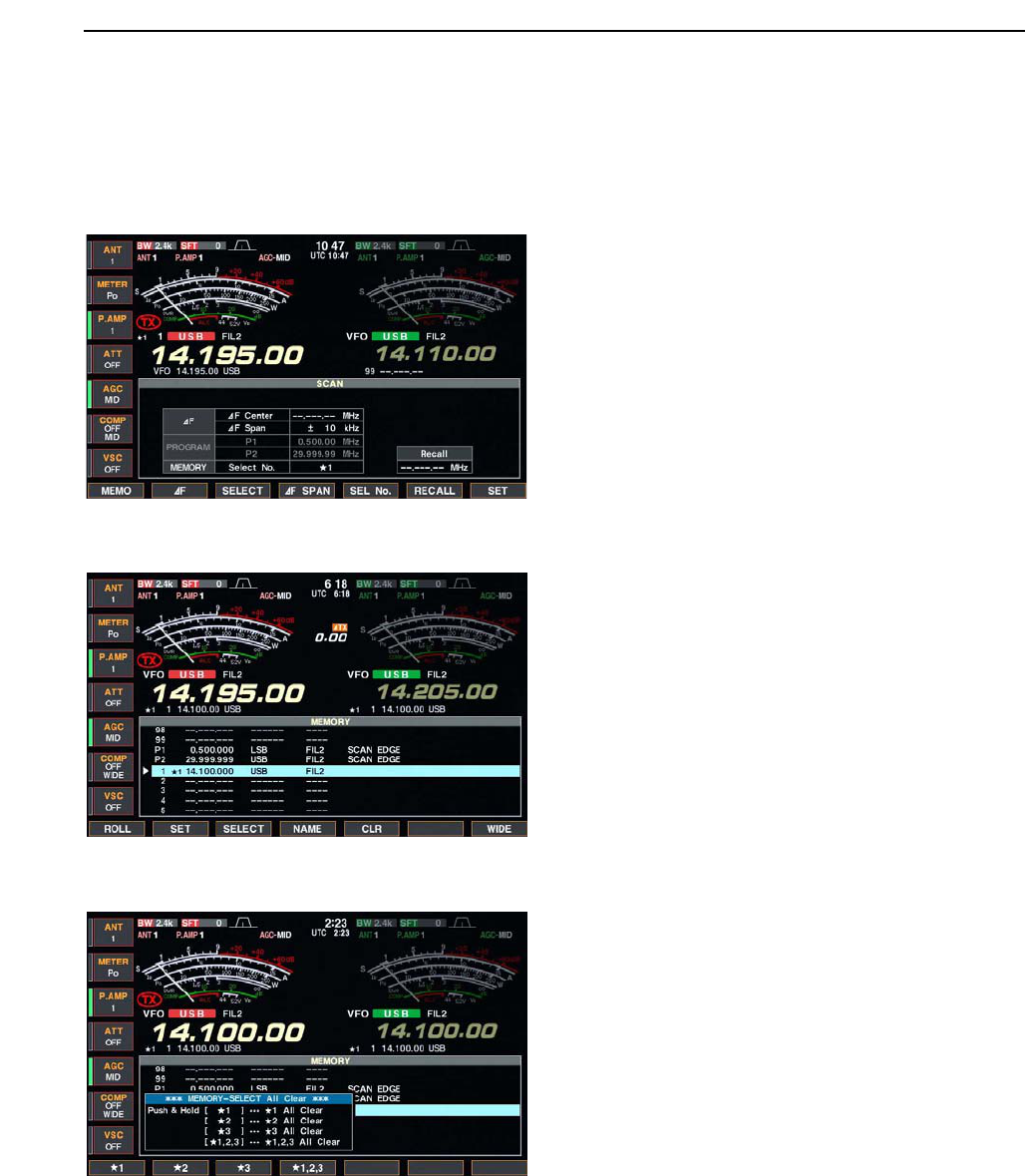
■Setting select memory channels
DSetting in scan screen
qPush [EXIT/SET] several times to close a multi-func-
tion screen, if necessary.
wSelect memory mode.
ePush [F-5•SCAN] to select the scan screen.
rSelect the desired memory channel to set as a se-
lect memory channel.
•[Y]/[Z] keys and direct keypad selections can be used.
tPush [F-3•SELECT] several times to set the mem-
ory channel as a select memory ★1, ★2, ★3 or not.
yRepeat steps rto tto program another memory
channel as a select memory channel, if desired.
uPush [EXIT/SET] to exit the scan screen.
DSetting in memory list screen
qPush [EXIT/SET] several times to close a multi-func-
tion screen, if necessary.
wPush [F-4•MEMORY] to select memory list screen.
eRotate the main dial while pushing [F-1•ROLL] or
[F-2•SET] to select the desired memory channel.
•[Y]/[Z] keys and direct keypad selections can be used.
rPush [F-3•SELECT] several times to set the mem-
ory channel as a select memory ★1, ★2, ★3 or not.
tRepeat steps eto rto program another memory
channel as a select memory channel, if desired.
yPush [EXIT/SET] to exit the memory list screen.
DErasing the select scan setting
qPush [EXIT/SET] several times to close a multi-func-
tion screen, if necessary.
wPush [F-4•MEMORY] to select memory list screen,
or push [F-5•SCAN] to select scan screen.
ePush [F-3•SELECT] for 1 sec. to display memory
select all clear window.
rPush one of the following keys to clear all select
scan setting.
[F-1•★1] : Clears all ★1 setting.
[F-2•★2] : Clears all ★2 setting.
[F-3•★3] : Clears all ★3 setting.
[F-4•★1,2,3] : Clears all select setting.
tPush [EXIT/SET] to exit the memory list screen.
9
SCANS
9-8
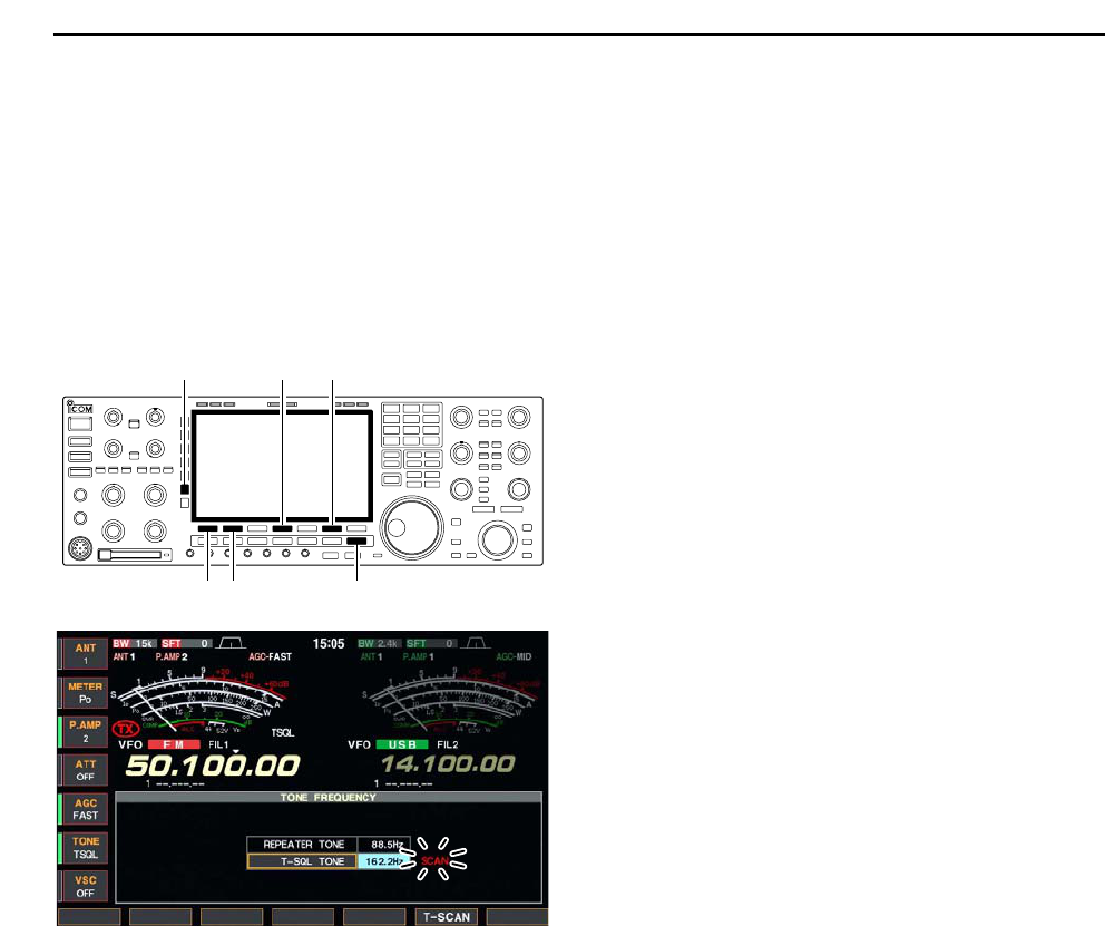
■Tone scan
The transceiver can detect the subaudible tone fre-
quency in a received signal. By monitoring a signal that
is being transmitted on a repeater input frequency, you
can determine the tone frequency required to access
the repeater.
qSet the desired frequency or memory channel to be
checked for a tone frequency.
wPush [AM/FM] several times to select FM mode.
ePush [TONE] for 1 sec. to enter tone frequency
screen.
rPush [F-1•Y] or [F-2•Z] to check the repeater tone
frequency or tone squelch frequency, respectively.
tPush [F-6•T-SCAN] to start the tone scan.
• “SCAN” blinks while scanning.
yWhen the tone frequency is detected, the tone scan
pauses.
• The tone frequency is set temporarily on a memory
channel. Program into the memory channel to store the
tone frequency permanently.
• The decoded tone frequency is used for the repeater
tone frequency or tone squelch frequency.
uTo stop the scan, push [F-6•T-SCAN].
• Push [F-4•DEF] for 1 sec. to select the default frequency.
iPush [EXIT/SET] to exit tone frequency screen.
[F-1•Y] [F-2•Z]
[TONE] [F-6•T-SCAN][F-4•DEF]
[EXIT/SET]
9SCANS

10-1
ANTENNA TUNER OPERATION Section 10
■Antenna connection and selection ………………………………… 10-2
■Antenna memory settings …………………………………………… 10-3
DAntenna type selection …………………………………………… 10-3
DTemporary memory ………………………………………………… 10-4
DAntenna selection mode …………………………………………… 10-4
■Antenna tuner operation ……………………………………………… 10-5
DTuner operation …………………………………………………… 10-5
DIf the tuner cannot tune the antenna …………………………… 10-6
10-2
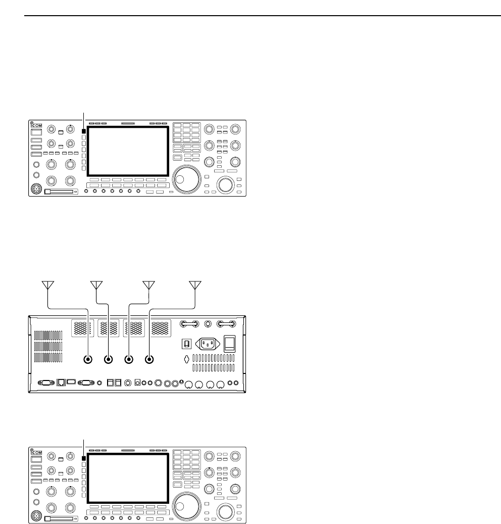
■Antenna connection and selection
The IC-7800 has 4 antenna connectors for the
HF/50 MHz bands, [ANT1], [ANT2], [ANT3], and
[ANT4].
For each operating band the IC-7800 covers, there is a
band memory which can memorize a selected an-
tenna. When you change the operating frequency be-
yond a band, the previously used antenna is automat-
ically selected (see below) for the new band. This
function is convenient when you use 4 antennas for HF
and 50 MHz bands operation.
• Antenna selection mode: “Auto”
Once an antenna has been selected for use with a
band by pushing [ANT], the antenna is automatically
selected whenever that band is accessed.
[EXAMPLE]: a 3.5/7 MHz antenna is connected to
[ANT1], a 21/28 MHz antenna is connected to [ANT2],
a 50 MHz antenna is connected to [ANT3]. When the
antenna selector function is set to “Auto,” an antenna
is automatically selected when changing bands.
[ANT4] can be used for receive only.
• Antenna selection mode: “Manual”
When “Manual” is selected, you can use the all an-
tenna connectors, [ANT1] [ANT2], [ANT3] and [ANT4],
however, band memory does not function. In this case
you must select an antenna manually.
• Antenna selection mode: “OFF”
In this case, only [ANT1] antenna connector can be
used. [ANT] switch does not function.
[ANT]
ANT 1
ANT 2 ANT 3
ANT 4
3.5/7 MHz
bands
21/28 MHz
bands
50 MHz
bands
RX
only
[ANT]
10 ANTENNA TUNER OPERATION
10-3
■Antenna memory settings
Storing the antenna connector number for each fre-
quency band to suit your antenna system.
qPush [EXIT/SET] several times to close multi-func-
tion screen, if necessary.
wPush [ANT] for 1 sec. to select antenna set screen.
eSelect the desired frequency band with a band key.
rPush [ANT] several times to select the desired an-
tenna number that you want to set for the selected
frequency band.
•“★” appears.
tPush [F-2•ANT MW] for 1 sec. to store the antenna
selection into the antenna memory.
•“★” disappears.
yRepeat the steps eto tto store the antenna se-
lection for another frequency bands, if desired.
uPush [EXIT/SET] to exit antenna set screen.
DAntenna type selection
When no antenna is connected to [ANT2], [ANT3],
and/or [ANT4], these antenna connector can be deac-
tivated— deleting the antenna number from selection.
This prevent the transceiver from accidental transmis-
sion with unmatched antenna selection.
In addition, receive only antenna can be specified to
[ANT4].
qSelect the antenna set screen as described above.
wPush [F-7•ANT TYPE] to select antenna type set
screen.
ePush [F-1•Y] or [F-2•Z] to select the desired an-
tenna.
rRotate the main dial to select the desired antenna
condition from TX/RX, RX (ANT4 only) and OFF.
• TX/RX : Select when an antenna is connected.
• OFF : Select when no antenna is connected.
• RX : Select when a receive only antenna is
connected. (available for the [ANT4] only)
tPush [EXIT/SET] to exit antenna type set screen.
✔
For your information
The antenna(s) that “OFF” is selected cannot be se-
lected with [ANT] switch operation, as well as the an-
tenna memory setting.
When “RX” is selected for [ANT4], “1/R,” “2/R” and
“3/R” selections will be added for the selection for both
[ANT] switch operation and the antenna memory set-
ting. In these selection, using the antenna connected
to [ANT1], [ANT2] and/or [ANT3] for transmission and
using the antenna connected to [ANT4] for reception.
[ANT]
[F-2•ANT MW]
Band keys
10
ANTENNA TUNER OPERATION
10-4
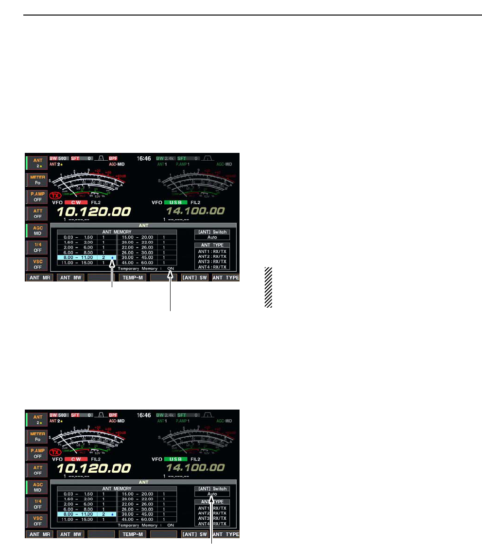
■Antenna memory settings (continued)
DTemporary memory
The antenna temporary memory memorize the manu-
ally selected antenna. The selected antenna will be re-
called even the frequency band has been changed.
qSelect the antenna set screen.
wPush [F-4•TEMP-M] to turn the temporary memory
ON and OFF.
eSelect the desired frequency band with a band key.
rPush [ANT] to select the desired antenna.
•“★” appears when a different antenna from the original is
selected.
tPush [F-1•ANT MR] to re-call the original antenna.
•“★” disappears.
yPush [EXIT/SET] to exit antenna set screen.
CAUTION!: Before transmitting with the manually
selected antenna, make sure the selected antenna
suits to the operating frequency. Otherwise the
transceiver may damage.
DAntenna selection mode
The automatic antenna selection (antenna memory)
and the [ANT] switch function can be deactivated if de-
sired.
qSelect the antenna set screen.
wPush [F-6•[ANT] SW] to select the antenna selec-
tion from Auto, OFF and Manual.
• Auto : Use the antenna memory. Antenna se-
lection with [ANT] switch is also avail-
able.
• OFF : The antenna connected to [ANT1] can
only be used. [ANT] switch is deacti-
vated.
• Manual : Deactivate the antenna memory func-
tion. Antenna can be selected with
[ANT] switch operation only.
ePush [EXIT/SET] to exit antenna set screen.
Push [F-6•[ANT] SW] to select the
antenna selection mode.
“★” appears when a different antenna
from the original is selected.
Push [F-4•TEMP-M] to turn the
temporary memory ON and OFF.
10 ANTENNA TUNER OPERATION

10-5
■Antenna tuner operation
The internal automatic antenna tuner matches the
transceiver to the connected antenna automatically.
Once the tuner matches an antenna, the variable ca-
pacitor angles are memorized as a preset point for
each frequency range (100 kHz steps). Therefore,
when you change the frequency range, the variable ca-
pacitors are automatically preset to the memorized
point.
CAUTION: NEVER transmit with the tuner ON when
no antenna is connected. This will damage the
transceiver. Be careful of the antenna selection.
DTuner operation
➥Push [TUNER] to turn the internal antenna tuner
ON. The antenna is tuned automatically when the
antenna SWR is higher than 1.5:1.
• When the tuner is ON, the “TUNE” indicator appears.
• MANUAL TUNING
During SSB operation at low voice levels, the internal
tuner may not be tuned correctly. In such cases, man-
ual tuning is helpful.
➥Push [TUNER] for 1 sec., to start manual tuning.
• A side tone is emitted and “TUNE” indicator blinks while
tuning.
• If the tuner cannot reduce the SWR to less than 1.5:1
after 20 sec. of tuning, the [TUNER] switch indicator
goes out.
• AUTOMATIC TUNER START (HF bands only)
If you want to deactivate the tuner under conditions of
VSWR 1.5:1 or less, use the auto tuner start function
and turn the tuner OFF. This function activates the
tuner automatically when the SWR exceeds 1.5:1.
This function is turned ON in set mode. (p. 12-14).
NOTES:
•NEVER transmit without an antenna properly con-
nected to antenna port in use.
• When 2 or more antennas are connected, select
the antenna to be used with [ANT].
• If the SWR is higher than about 1.5:1 when tuning
above 100 kHz on an antenna’s preset point, push
[TUNER] for 1 sec. to start manual tuning.
• The internal tuner may not be able to tune in AM
mode. In such cases, push [TUNER] for 1 sec. to
manually tune.
[TUNER]
10
ANTENNA TUNER OPERATION

10-6
■Antenna tuner operation (continued)
• PTT TUNER START
The tuner is always tuned when the PTT is pushed
after the frequency is changed (more than 1% from
last-tuned frequency). This function removes the “push
and hold [TUNER]” operation and activates for the first
transmission on a new frequency.
This function is turned ON in set mode. (p. 12-14).
• Antenna tuner of the IC-PW1
When using an external antenna tuner such as the IC-
PW1’s tuner, tune with the external antenna tuner,
while the internal tuner is turned OFF. After tuning is
completed, turn the internal tuner ON. Otherwise, both
tuners tune simultaneously and correct tuning may not
be obtained.
See the instruction manual included with each antenna
tuner for their respective operations.
DIf the tuner cannot tune the antenna
Check the following and try again:
• the [ANT] connector selection.
• the antenna connection and feedline.
• the unaltered antenna SWR. (Less than 3:1 for HF bands; Less
than 2.5:1 for 50 MHz band)
• the transmit power. (8 W for HF bands; 15 W for 50 MHz band)
• the power source voltage/capacity.
If the tuner cannot reduce the SWR to less than 1.5:1
after checking the above, perform the following:
• repeat manual tuning several times.
• tune with a 50 Ωdummy load and re-tune the antenna.
• turn power OFF and ON.
• adjust the antenna cable length.
(This is effective for higher frequencies in some cases.)
• Some antennas, especially for low bands, have a narrow
bandwidth. These antennas may not be tuned at the edge
of their bandwidth, therefore, tune such an antenna as fol-
lows:
[Example]: Suppose you have an antenna which has an
SWR of 1.5:1 at 3.55 MHz and an SWR of 3:1
at 3.8 MHz.
qPush [TUNER] to turn the antenna tuner ON.
wSelect CW mode.
eTurn OFF the break-in function. (p. 6-3)
rPush [TRANSMIT] to set to the transmit condition.
tSet 3.55 MHz and key down.
ySet 3.80 MHz and key down.
uPush [TRANSMIT] to return to the receive condition.
10 ANTENNA TUNER OPERATION

11-1
CLOCK AND TIMERS Section 11
■Time set mode ………………………………………………………… 11-2
■Daily timer setting ……………………………………………………… 11-3
■Setting sleep timer …………………………………………………… 11-4
■Timer operation ………………………………………………………… 11-4
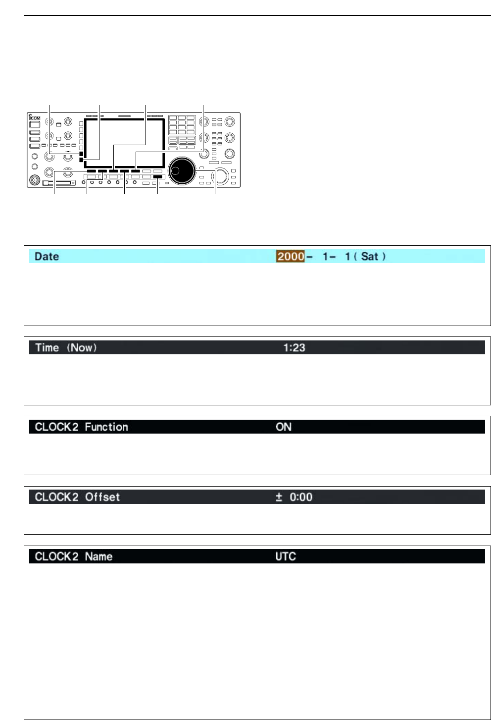
11-2
■Time set mode
The IC-7800 has a built-in calender and 24-hour clock
with daily power ON/OFF timer functions. Before oper-
ating these timer functions, set the current date and
time, etc.
qPush [EXIT/SET] to close multi-function screen, if
necessary.
wPush [F-7•SET] to select set mode menu screen.
ePush [F-4•TIME] to select time set mode.
rPush [F-1•Y] or [F-2•Z] to select the desired item.
tRotate the main dial to set or select the desired
value or condition.
yPush [EXIT/SET] to exit time set mode.
[EXIT/SET][F-4•DEF]
[ABC]/[abc] [123]/[Symbol] [F-3•Ω≈][F-5•EDIT]/[F-5•SET]
[F-1•Y] [F-2•Z] Main dial
11 CLOCK AND TIMERS
Sets the date. zPush [F-3•Ω≈] to select between the year and the
month/day, then rotate the main dial to select them.
• The date setting and “DATE-set Push [SET]” indication
blink.
xPush [F-5•SET] to set the date.
Sets the local time. zRotate the main dial to set the local time.
• The time setting and “TIME-set Push [SET]” indication
blink.
xPush [F-5•SET] to set the time.
Turns the clock 2 indication ON and OFF.
The clock 2 is convenient to indicate the UTC or other
country’s local time, etc.
• ON : The clock 2 is displayed below the local time
indication.
• OFF : The clock 2 does not display.
Sets the desired off-set time period for the clock 2 in-
dication within –24:00 to +24:00 in 1 min. steps.
• Pushing [F-4•DEF] for 1 sec. to select the default value.
Sets the desired 3-character name for the clock 2.
Capital letters, small letters, numerals, some symbols
(! # $ % & ¥ ? " ’ ` ^ + – ✱/ . , : ; = < > ( ) [ ] { } | _ ~@)
and spaces can be used.
zPush [F-5•EDIT] to select the name edit condition.
• The 1st character and cursor blink.
xPush [ABC], [abc], [123] or [Symbol] to select the
character group, then rotate the main dial to select
the character.
• Push [ABC] or [abc] to toggle capital and small letters.
• Push [123] or [Symbol] to toggle numerals and sym-
bols.
• Push [F-1•Ω] or [F-2•≈] for cursor movement.
• Push [F-3•DEL] to delete the selected character.
• Push [F-4•SPACE] to input a space.
• Pushing the transceiver’s keypad, [0]–[9], can also
enter numerals.
cPush [EXIT/SET] to set the name.
11-3
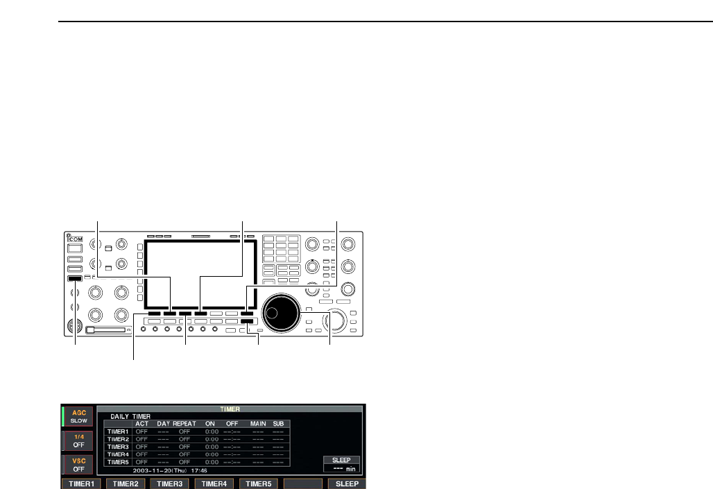
■Daily timer setting
The transceiver turns power ON and/or OFF automat-
ically on the specified day of the week and time with
the specified frequency settings in each main and sub
readout.
qPush [EXIT/SET] several times to close multi-func-
tion screen, if necessary.
wPush [TIMER] for 1 sec. to select timer set screen.
ePush one of [F-1•TIMER1] to [F-4•TIMER4] to se-
lect the desired timer.
rRotate the main dial to select the timer action ON
and OFF.
tPush [F-2•≈] to select the “DAY” cell, then rotate the
main dial to select the desired day of the week.
• Select “– – –” to not specifying the day of the week. The
timer will function every day in this case.
• Once a day of the week is selected, push [F-4•CLR] for
1 sec. to select “– – –.”
yPush [F-2•≈] to select the “REPEAT” cell, then ro-
tate the main dial to select the repeat function ON
and OFF.
• ON : The timer functions every selected day of the
week.
• OFF : The timer functions only coming day of the week.
uPush [F-2•≈] to select the “ON” cell, then rotate the
main dial to set the desired transceiver power ON
time.
• When using power OFF timer only, push [F-4•CLR] for
1 sec. to select “– – –.”
iPush [F-2•≈] to select the “OFF” cell, then rotate the
main dial to set the desired transceiver power OFF
time.
• When using power ON timer only, push [F-4•CLR] for
1 sec. to select “– – –.”
oPush [F-2•≈] to select the “MAIN” cell, then rotate
the main dial to select the desired memory channel
number in the main readout.
• If using the currently set VFO condition in main readout,
push [F-4•CLR] for 1 sec. to select “– – –.”
!0 Push [F-2•≈] to select the “SUB” cell, then rotate the
main dial to select the desired memory channel
number in the sub readout.
• If using the currently set VFO condition in sub readout,
push [F-4•CLR] for 1 sec. to select “– – –.”
!1 Push [F-7•SET] to set the timer.
• The timer indicator above [TIMER] switch lights green.
!2 Repeat the steps eto !1 to set another timers, if
desired.
!3 Push [EXIT/SET] to exit timer set screen.
[EXIT/SET]
[F-4•TIMER4]/[F-4•CLR]
[F-3•TIMER3]
[TIMER]
[F-7•SET]
[F-1•TIMER1]/[F-1•Ω]
[F-2•TIMER2]/[F-2•≈]
Main dial
11
CLOCK AND TIMERS
11-4
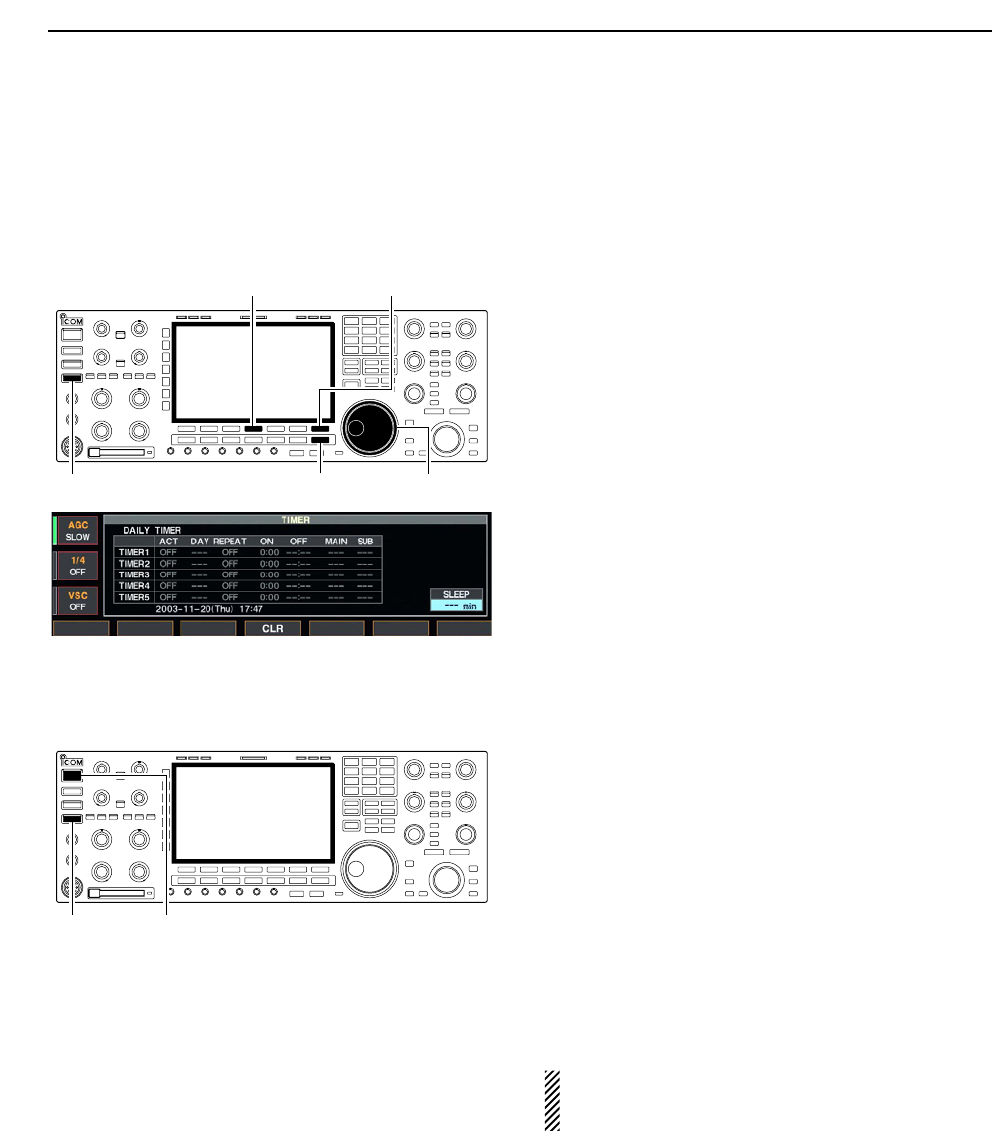
■Setting sleep timer
The sleep timer turns the transceiver power OFF au-
tomatically after passing the set period. The timer can
be set to 5–120 min. in 5 min. steps.
qPush [EXIT/SET] several times to close a multi-func-
tion screen, if necessary.
wPush [TIMER] for 1 sec. to select timer set screen.
ePush [F-7•SLEEP] to select the sleep timer set con-
dition.
• “– – –” blinks.
rSet the desired time period using the main dial.
• “TIMER–set Push [SET]” blinks.
• Push [F-4•CLR] to select “– – –” to cancel the setting.
tPush [F-7•SET] to set the time.
• Push [EXIT/SET] to cancel the setting.
• The timer indicator above [TIMER] switch lights green.
yPush [EXIT/SET] to exit timer set screen.
uThe transceiver emits 10 beeps and turns OFF after
the sleep timer period elapses.
• The timer indicator blinks while beeping.
• Push [TIMER] momentarily to cancel the sleep timer, if
desired.
■Timer operation
qPreset the daily timer as described previously.
wPush [TIMER] momentarily to turn the timer function
ON.
• The timer indicator above this switch lights green when
the timer function is ON.
ePush [POWER] for 1 sec. to turn the power OFF.
• The timer indicator lights continuously.
rWhen the set time arrives, the power is automati-
cally turned ON.
tThe transceiver emits 10 beeps and turns OFF after
the power-off period elapses.
• The timer indicator blinks while beeping.
• Push [TIMER] momentarily to cancel the sleep timer, if
desired.
The timer action in timer set screen must be se-
lected ON to enable the timer operation, described
in page 11-3 steps r.
[TIMER] [POWER]
[EXIT/SET]
[F-4•CLR]
[TIMER]
[F-7•SLEEP]/[F-7•SET]
Main dial
11 CLOCK AND TIMERS