ICOM orporated 262700 FRS UHF FM Transceiver User Manual Revised
ICOM Incorporated FRS UHF FM Transceiver Users Manual Revised
UserManual.wiki
>
ICOM orporated
>
262700 User Manual
Users Manual Revised
Navigation menu
Upload a User Manual
Namespaces
Wiki Guide
HTML
PDF
Info
Views
User Manual
Discussion / Help
Navigation
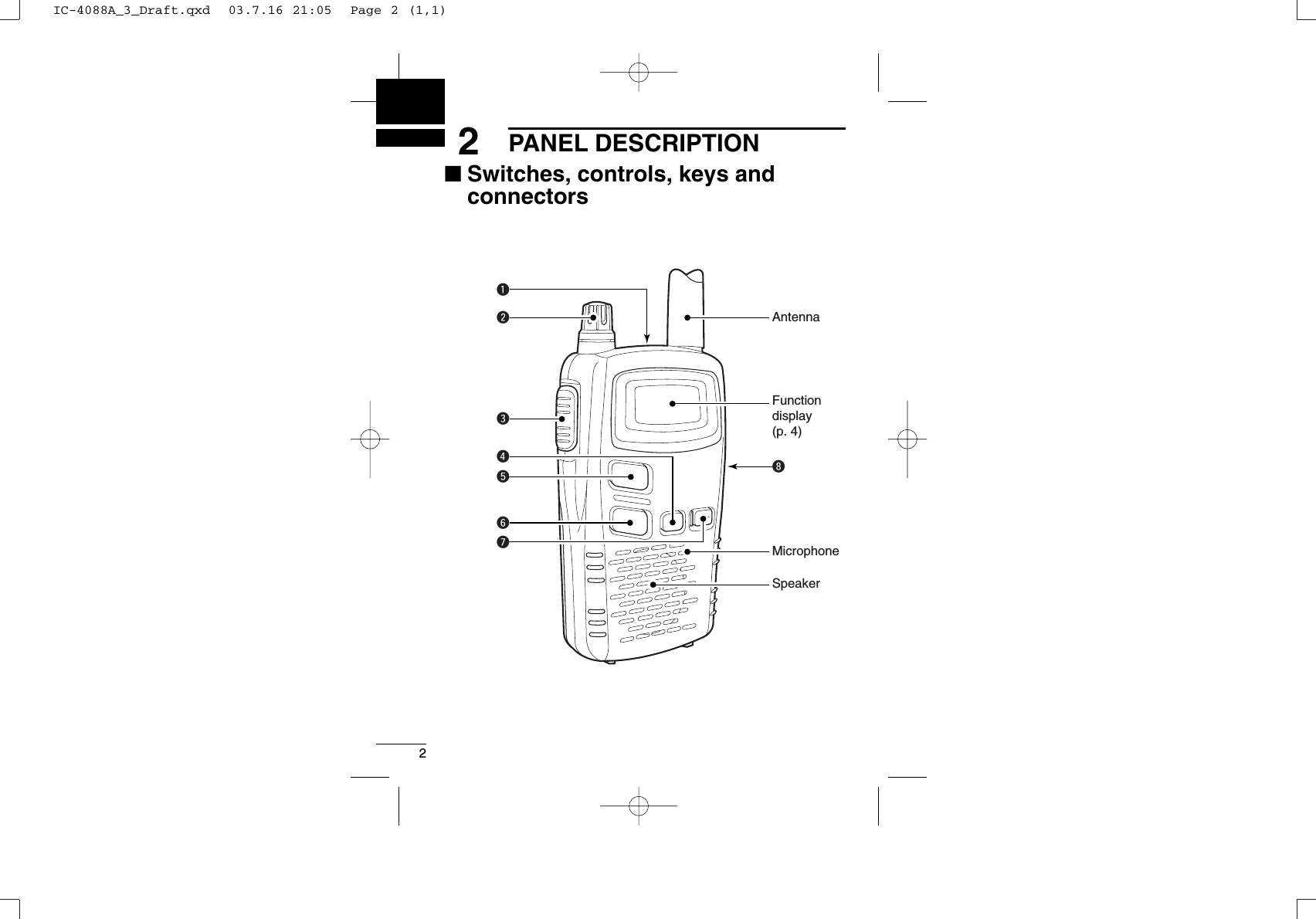
![32PANEL DESCRIPTION2qEXTERNAL SPEAKER AND MICROPHONE JACKSConnect an optional speaker-microphone or headset, if desired. wVOLUME CONTROL [VOL]Rotate clockwise to increase and counterclockwise to decreasevolume.ePTT SWITCH [PTT]Push and hold to transmit; release to receive.rMODE SWITCH [MODE]➥Push to enter and select set mode for group (p. 12) and voicescrambler code. (p. 16)➥Push and hold for 1 sec. to turn the monitor function ON andOFF. (p. 8)tCHANNEL UP SWITCH [Y]➥Push to increment the operating channel.➥Push and hold to increment the operating channel continu-ously.➥While scanning, changes scanning direction. (p. 14)yCHANNEL DOWN SWITCH [Z]➥Push to decrement the operating channel.➥Push and hold to decrement the operating channel continu-ously.➥While scanning, changes scanning direction. (p. 14)uPOWER SWITCH [PWR]➥Push to turn the power ON.➥Push and hold this key to toggle the key lock functionON/OFF. (p. 19)iEXTERNAL DC IN JACK [DC 6V] (p. 6)Connects the optional AC adapter or cigarette lighter cable forboth operation and battery charging.IC-4088A_3_Draft.qxd 03.7.16 21:05 Page 3 (1,1)](https://usermanual.wiki/ICOM-orporated/262700/User-Guide-341094-Page-9.png)
![63BATTERY CHARGING■Charging connectionsDDRegular charging with the BC-149A, CP-18A➥Connect the optional BC-149AAC ADAPTERor CP-18ACIGARETTELIGHTER CABLEto [DC 6V].•Charging period: approx. 15 hoursIMPORTANT!:Use the BC-149A or CP-18A ONLY. Other type of AC adapter,cigarette lighter cable or DC power cable with an external powersupply may damage the transceiver.The optional BP-202 can only be charged— other AA (R6) sizerechargeable Ni-Cd cannot be charged.BE SURE to disconnect the CP-18A from the cigarette lightersocket when charging is finished, because, a slight current stillfollows in the CP-18A and the vehicle’s battery will become ex-hausted.to [DC 6V]jackOptional CP-18ACigarette lighter cable with DC-DC converterOptional BC-149Ato cigarette lighter socketto AC outletIC-4088A_3_Draft.qxd 03.7.16 21:05 Page 6 (1,1)](https://usermanual.wiki/ICOM-orporated/262700/User-Guide-341094-Page-12.png)
![73BATTERY CHARGING3DDRapid charging with the BC-119N+AD-105qInsert the optional AD-105 DESKTOP CHARGER ADAPTERinto thecharging slot of the BC-119N.wInsert the battery pack, either by itself or attached to the trans-ceiver, into the charger. IC-4088A BP-202AD-105BC-119NAC adapterNOT used: Fix the 3-pin connector to the bottom of the charger with the adhesive tape, etc., to prevent catching or touching the 3-pin connector’s terminals with the adapter’s leads, etc.**NOTE: Put the Ni-Cd battery adapter into the AD-105 rear slot when the BP-202 is attached to the transceiver.Turn the power OFF! When the installed Ni-Cd battery is nearly exhausted and the function display blinks in intermittently, push [PWR] until the trans-ceiver’s power goes OFF.IC-4088A_3_Draft.qxd 03.7.16 21:05 Page 7 (1,1)](https://usermanual.wiki/ICOM-orporated/262700/User-Guide-341094-Page-13.png)
![84BASIC OPERATION■Power ON➥Push [PWR] for 1 sec. to turnthe power ON.•“ ” and operating channel num-ber appear on the display.■Adjusting the volumeqPush and hold [MODE] for1 sec. to open the squelch(monitor function ON).•“ ” indicator appears on the dis-play while the squelch is open.wAdjust the audio to a suitablelevel using [VOL].ePush and hold [MODE] for1 sec. to close the squelch.✔What is squelch?A squelch circuit allows muting of undesired noise while receivingno signal and emit audio while receiving signals.This provides quiet standby. The [MODE] key changes thesquelch setting. This is useful to listen to weak signals that donot open the squelch.[PWR][MODE]Appears[VOL]IC-4088A_3_Draft.qxd 03.7.16 21:05 Page 8 (1,1)](https://usermanual.wiki/ICOM-orporated/262700/User-Guide-341094-Page-14.png)
![94BASIC OPERATION4■Selecting the operating channelPush [Y] or [Z] keys several timesuntil the desired operating channelnumber appears on the display.•While pushing and holding [Y] or[Z] keys, the displayed channelchanges continuously until chan-nel number “1” appears.To keep the automatic selection,release the [Y] or [Z] keys thenpush and hold them again.•When displayed channel stops at channel number “1,” a beep isemitted. NOTE:•The transceiver has 14 operating frequency channels.• The selected channel is memorised when the transceiver isturned off.[Y][Z]IC-4088A_3_Draft.qxd 03.7.16 21:05 Page 9 (1,1)](https://usermanual.wiki/ICOM-orporated/262700/User-Guide-341094-Page-15.png)
![105RECEIVE AND TRANSMITqSelect the desired operatingchannel with [Y]/[Z].When a signal is received:• “” indicator appears on thedisplay.•Squelch opens and audio isemitted from the speaker.- Further adjustment of [VOL]may be necessary at this point.wPush and hold [PTT] to transmitthen speak into the microphone.•Do not hold the transceiver tooclose to your mouth or speak tooloudly. This may distort the sig-nal.•The transmit indicator “” ap-pears on the display.eRelease [PTT] to return to re-ceive.IMPORTANT:To maximize the readability of the transmitted signal, pause afew sec. after pushing [PTT], hold the transceiver 4 to 6 in. (10 to15 cm) from your mouth and speak at a normal voice level.NOTE:The transceiver has an auto power save function to conservethe battery power. The power save function activates automati-cally when no signal is received for 5 sec.[Y][Z][PTT]AppearsIC-4088A_3_Draft.qxd 03.7.16 21:05 Page 10 (1,1)](https://usermanual.wiki/ICOM-orporated/262700/User-Guide-341094-Page-16.png)
![126GROUP MODE (CTCSS)■Setting the group codeThe IC-4088A is equipped with 38 group codes. Group mode oper-ation provides communication with silent standby since you will onlyreceive calls from group members using the same group number.First of all, set the same group code number for all group member’stransceivers.To turn ON the group mode op-eration:qPush [MODE] to enter set mode.•“---” (group mode OFF) appearson the display. wPush [Y] or [Z] to select the de-sired code number.ePush [MODE] twice to set thegroup code number and exit setmode.To cancel the group mode oper-ation:qPush [MODE] to enter set mode. •Channel number disappears onthe display. wPush [Y] or [Z] to select “---”(group mode OFF).ePush [MODE] twice to cancelthe group mode and return tooperating condition.NOTE: Only stations with the same group channel number canbe heard during group mode operation, even when the busy in-dicator appears on the display. [Y][Z][MODE]IC-4088A_3_Draft.qxd 03.7.16 21:05 Page 12 (1,1)](https://usermanual.wiki/ICOM-orporated/262700/User-Guide-341094-Page-18.png)
![136GROUP MODE (CTCSS)6DDCTCSS code table(unit: Hz)CH Freq. CH Freq. CH Freq. CH Freq.01 67.0 11 97.4 21 136.5 31 192.802 71.9 12 100.0 22 141.3 32 203.503 74.4 13 103.5 23 146.2 33 210.704 77.0 14 107.2 24 151.4 34 218.105 79.7 15 110.9 25 156.7 35 225.706 82.5 16 114.8 26 162.2 36 233.607 85.4 17 118.8 27 167.9 37 241.808 88.5 18 123.0 28 173.8 38 250.309 91.5 19 127.3 29 179.9 --- OFF10 94.8 20 131.8 30 186.2✔What is CTCSS (Continuous Tone Coded Squelch System)GROUP MODE ?CTCSS (Continuous Tone Coded Squelch System) GROUPMODE allows communication with silent stand by. Only signalscontaining a specific group code can open the squelch.This conveniently eliminates unwanted audio and is useful ingroup activities or security related activities where unwanted out-put can be a problem. Note that CTCSS group mode is not pri-vate—anyone can receive your calls.The IC-4088A is equipped with 38 tone codes for CTCSS GROUPMODE use. Selecting a code applies it to all 14 operating chan-nels. Each push of [PTT] superimposes your group code over yourtransmit signal; and, only signals containing the same code canopen your squelch. To temporarily hear all signals (including noise)push and hold [MODE]. Do not use CTCSS GROUP MODE if youwant to be able to hear signals on all channels.IC-4088A_3_Draft.qxd 03.7.16 21:05 Page 13 (1,1)](https://usermanual.wiki/ICOM-orporated/262700/User-Guide-341094-Page-19.png)
![147SCAN FUNCTIONScanning is an efficient way to locate signals quickly over all chan-nels. Select scan resume condition in advance, using Initial SetMode (p. 17)DStarting the scan➥While pushing [Y], push [Z] tostart the scan.• “-” flashes.• While pushing [Z], pushing[Y] also starts the scan.• Push [Z] or [Y] to change thescanning direction or resumethe scan manually.• To cancel the scan, push [Z](or [Y]) while [Y] (or [Z]) ispushed, or push [PTT].CH 14 CH 3CH 2CH 1CH 4CH 5[Z][Y]IC-4088A_3_Draft.qxd 03.7.16 21:05 Page 14 (1,1)](https://usermanual.wiki/ICOM-orporated/262700/User-Guide-341094-Page-20.png)
![158RING FUNCTIONS78■Smart-Ring The ring function has an answer back feature. This allows confir-mation of whether or not a call has reached the receiving party evenif the operator is temporarily away from the transceiver.qSet the same group channelnumber for all of the grouptransceivers. (See p. 12)wWhile pushing [PTT], push [Y] .•A beep is emitted and “” blinkson the display.eRelease the [PTT].• When a member of a specificgroup answers a call, the trans-ceiver emits beep tones for10 sec. and blinks “.”•When no answer comes back, the transceiver emits short faintbeep tones. rPush [PTT] to answer and to stop the beeps and flashing.NOTE: This function is available only when the called station hasset the same group number and the same operating channelsas you.■Call-Ring Sends the ring tones during trans-mit mode.➥While pushing [PTT], push [Z]to send a ring tone.•The ring tone is emitted whilepushing [Z]. •The microphone signal is auto-matically cut while pushing [Z].[PTT][Y][PTT][Z]IC-4088A_3_Draft.qxd 03.7.16 21:05 Page 15 (1,1)](https://usermanual.wiki/ICOM-orporated/262700/User-Guide-341094-Page-21.png)
![169OTHER FUNCTIONS■Voice scrambler functionThe voice scrambler function provides communication privacy. qPush [MODE] twice to select voice scram-bler setting mode.•“Sr-” appears on the display.wPush [Y]/[Z] to turn the function ON andOFF.•“ ” appears when the voice scrambler isactivated.ePush [MODE] to exit voice scrambler set-ting mode.NOTE: All transceivers in a specific groupMUST turn ON the voice scrambler func-tion. Otherwise the communication will notpossible.■Initial set modeInitial set mode is accessed at power ON and allows the setting ofseldom changed settings. In this way the user can “customize” trans-ceiver operations to suit specific preferences and operating style.DDEntering initial set modeqWhile pushing [MODE], push[PWR] for 1 sec. to enter initialset mode.wPush [MODE] to select the de-sired item.ePush [Y]/[Z] to select the con-dition or value as desired.rPush [PWR] to exit initial setmode.[Y][Z][MODE][PWR]IC-4088A_3_Draft.qxd 03.7.16 21:05 Page 16 (1,1)](https://usermanual.wiki/ICOM-orporated/262700/User-Guide-341094-Page-22.png)
![DRing tone typeRing tone is selectable with 10 different indi-vidual sounds.DDLCD backlightThe IC-4088A has LCD backlight light for nighttime operation, andthe lighting condition can be selected to suits a specific preference,from Auto, ON and OFF.Auto (At) : Lights when any switch,except [PTT], is pushed.When no key operation isperformed for 5 sec., thebacklight goes OFF.ON (on) : Lights continuously. OFF (oF) : Never lights.189OTHER FUNCTIONSIC-4088A_3_Draft.qxd 03.7.16 21:05 Page 18 (1,1)](https://usermanual.wiki/ICOM-orporated/262700/User-Guide-341094-Page-24.png)
![1999OTHER FUNCTIONS■Lock functionThis function electronically locks all keys and switches to preventaccidental channel changes and function access.➥Continue to hold [PWR] down for2 sec. after power ON to turn the lockfunction ON and OFF.•“ ” appears on the display.- Only [PWR] and [PTT] are functional. - The Ring function is also available.(See p. 15)■Low battery indicator➥Appears when the battery is nearingexhaustion.•A warning beep is emitted while turn-ing the power ON.➥Blinks when battery replacement isnecessary.•When the indicator blinks, the trans-ceiver may not be operated. (Notguaranteed)‘‘Auto power save➥The power save function reduces the current drain to conservebattery power. - The function automatically turns ON when no operation is per-formed and no signal is received for 5 sec.“ ” appears when thelock function is in use.Appears when the batteryis nearing exhaustion.Blinks when battery replacement is necessary.IC-4088A_3_Draft.qxd 03.7.16 21:05 Page 19 (1,1)](https://usermanual.wiki/ICOM-orporated/262700/User-Guide-341094-Page-25.png)
![209OTHER FUNCTIONS■ATS (Automatic Transponder System)This allows the user to confirm whether or not a call has reachedthe receiving party even if the operator is temporarily away from thetransceiver. No “Ring” tone is emitted with this function.➥While pushing [PTT], push[MODE] to turn the function ONand OFF. •“ ” appears on the display. •The transceiver starts to send asearching signal every 60 sec.- When the transceiver receivesan answer back signal, “”stays on the display until thenext search transmit.- If no reply is received, “” blinks until the next search transmit.NOTE: Above setting is for the calling station only. A called partyautomatically sends an answer back signal without any preset-tings. All IC-4088A’s operating on the same operating channelwill answer back to the call in the surroundings communicationsarea. ‘‘Resetting the transceiverInitialize the operating conditionsbefore using the transceiver for thefirst time, or if the function displayshows erroneous information.➥ While pushing [Z] and [MODE],push [PWR] for 1 sec. to initial-ize the transceiver.CAUTION: Resetting the trans-ceiver returns all settings totheir defaults.[PTT][MODE][MODE][PWR][Z]IC-4088A_3_Draft.qxd 03.7.16 21:05 Page 20 (1,1)](https://usermanual.wiki/ICOM-orporated/262700/User-Guide-341094-Page-26.png)
![219OTHER FUNCTIONS9■Optional HM-75A functionsThe optional HM-75A allows remotely selected operating channels,open the squelch, etc. The switches on the HM-75A function as fol-lows. CAUTION: When connecting the HM-75A to the transceiver,make sure that power to the transceiver is turned OFF, other-wise the transceiver may malfunction.DSwitch actionSWITCHABUPDOWNNORMALSmart-RingOpen squelchChange the oper-ating channelnumber up.Change the oper-ating channelnumber down.While holding HM-75A’s [PTT] No functionNo functionSmart-RingCall-RingAOFF ONLOCKBLock switch:Locks allswitchesexcept [PTT]EarphonejackPTT switchIC-4088A_3_Draft.qxd 03.7.16 21:05 Page 21 (1,1)](https://usermanual.wiki/ICOM-orporated/262700/User-Guide-341094-Page-27.png)