ICOM orporated 262700 FRS UHF FM Transceiver User Manual Revised
ICOM Incorporated FRS UHF FM Transceiver Users Manual Revised
Users Manual Revised

INSTRUCTION MANUAL
FRS UHF FM TRANSCEIVER
i4088A
This device complies with Part 15 of the FCC rules. Oper-
ation is subject to the following two conditions: (1) This de-
vice may not cause harmful interference, and (2) this
device must accept any interference received, including in-
terference that may cause undesired operation.
IC-4088A_3_Draft.qxd 03.7.16 21:05 Page A (1,1)

i
Safety Training Information
Your FRS radio generates RF electromagnetic energy during trans-
mit mode. This radio is intended for use by “General Population” in
uncontrolled environment.
This radio has been tested and complies with the FCC RF expo-
sure limits for “General population.” In addition, your Icom radio
complies with the following Standards and Guidelines with regard to
RF energy and electromagnetic energy levels and evaluation of
such levels for exposure to humans:
• FCC OET Bulletin 65 Edition 01-01 Supplement C, Evaluating
Compliance with FCC Guidelines for Human Exposure to Radio
Frequency Electromagnetic Fields.
• American National Standards Institute (C95.1-1992), IEEE
Standard for Safety Levels with Respect to Human Exposure to
Radio Frequency Electromagnetic Fields, 3 kHz to 300 GHz.
• American National Standards Institute (C95.3-1992), IEEE Rec-
ommended Practice for the Measurement of Potentially Haz-
ardous Electromagnetic Fields- RF and Microwave.
• The following accessories are authorized for use with this prod-
uct. Use of accessories other than those specified may result in
RF exposure levels exceeding the FCC requirements for wire-
less RF exposure.; Belt Clip, Rechargeable Ni-Cd Battery Pack
(BP-202), Speaker microphones (HM-46/HM-75A/HM-131),
Earphone microphone (HM-128), Headset (HS-85) and
VOX/PTT case (VS-1) + Microphones (HS-94/HS-95/HS-97).
IC-4088A_3_Draft.qxd 03.7.16 21:05 Page i (1,1)

ii
fety Training Information
To ensure that your expose to RF electromagnetic energy is
within the FCC allowable limits for general population/uncon-
trolled use, always adhere to the following guidelines:
•DO NOT transmit for more than 50% of total radio use time
(“50% duty cycle”). Transmitting more than 50% of the time can
cause FCC RF exposure compliance requirements to be ex-
ceeded. The radio is transmitting when the “TX indicator” lights
red. You can cause the radio to transmit by pressing the "PTT"
switch.
The information listed above provides the user with the information
needed to make user aware of RF exposure, and what to do to as-
sure that this radio operates with the FCC RF exposure limits of this
radio.
SUPPLIED ACCESSORY
• Belt clip ………………………………… 1
Icom, Icom Inc. and the are registered trademarks of Icom Incor-
porated (Japan) in the United States, the United Kingdom, Germany,
France, Spain, Russia and/or other countries.
IC-4088A_3_Draft.qxd 03.7.16 21:05 Page ii (1,1)

iii
IMPORTANT
READ ALL INSTRUCTIONS carefully and completely before
using the transceiver.
SAVE THIS INSTRUCTION MANUAL— This instruction man-
ual contains important operating instructions for the transceiver.
PRECAUTION
RDANGER! NEVER operate the transceiver near un-
shielded electrical blasting caps or in an explosive atmosphere.
RWARNING! NEVER hold the transceiver so that the
antenna is very close to, or touching exposed parts of the body,
especially the face or eyes, while transmitting. The transceiver
will perform best if the microphone is 2 to 4 in. (5 to 10 cm)
away and the transceiver is vertical.
RWARNING! NEVER operate the transceiver with a
headset or other audio accessories at high volume levels. Hear-
ing experts advise against continuous high volume operation. If
you experience a ringing in your ears, reduce the volume or dis-
continue use.
NEVER attempt to charge alkaline cell batteries. Be aware
that external DC power connections will charge batteries inside
the battery case. This will damage not only the battery case but
also the transceiver.
DO NOT push the PTT when not actually desiring to trans-
mit.
IC-4088A_3_Draft.qxd 03.7.16 21:05 Page iii (1,1)

iv
PRECAUTION— continued
USE the optional AC adapter or cigarette lighter cable only for
both operating the transceiver and charging the battery. Other
manufacturer’s AC adapter, cigarette lighter cable or DC power
cable with external power supply may damage the transceiver.
Place the unit in a secure place to avoid inadvertent use by chil-
dren.
AVOID using or placing the transceiver in direct sunlight or in
areas with temperatures below –4˚F (–20°C) or above +122˚F
(+50°C).
The use of non-Icom battery packs/chargers may impair trans-
ceiver performance and invalidate the warranty.
Even when the transceiver power is OFF, a slight current still
flows in the radio. Remove the alkaline cells or battery pack
from the transceiver when not using it for a long time. Other-
wise, the installed batteries will become exhausted.
FCC WARNING: NEVER open the transceiver’s case to make
any internal adjustments, changes or modifications by a person
who not expressly approved by Icom Inc., could void your au-
thority to operate this transceiver under FCC regulations.
Any transceiver’s adjustments, replacement must be made by a
qualified technician using the proper test equipment.
IC-4088A_3_Draft.qxd 03.7.16 21:05 Page iv (1,1)

v
TABLE OF CONTENTS
Safety Training Information …………………………………………………… i
SUPPLIED ACCESSORY……………………………………………………… ii
IMPORTANT …………………………………………………………………… iii
PRECAUTION ……………………………………………………………… iii–iv
TABLE OF CONTENTS ……………………………………………………… v
1 PREPARATION …………………………………………………………… 1
■Belt clip attachment ……………………………………………………… 1
■Battery installation ……………………………………………………… 1
2 PANEL DESCRIPTION ………………………………………………… 2–4
■Switches, controls, keys and connectors ……………………………… 2
■Function display ………………………………………………………… 4
3 BATTERY CHARGING ………………………………………………… 5–7
■Battery caution …………………………………………………………… 5
■Charging connections …………………………………………………… 6
4 BASIC OPERATION …………………………………………………… 8–9
■Power ON ………………………………………………………………… 8
■Adjusting the volume …………………………………………………… 8
■Selecting the operating channel………………………………………… 9
5 RECEIVE AND TRANSMIT ………………………………………… 10–11
6 GROUP MODE (CTCSS) …………………………………………… 12–13
■Setting the group code ………………………………………………… 12
7 SCAN FUNCTION ………………………………………………………… 14
8 RING FUNCTIONS ……………………………………………………… 15
■Smart-Ring ……………………………………………………………… 15
■Call-Ring ………………………………………………………………… 15
9 OTHER FUNCTIONS ………………………………………………… 16–21
■Voice scrambler function ……………………………………………… 16
■Initial set mode ………………………………………………………… 16
■Lock function …………………………………………………………… 19
■Low battery indicator …………………………………………………… 19
■Auto power save………………………………………………………… 19
■ATS (Automatic Transponder System) ……………………………… 20
■Resetting the transceiver ……………………………………………… 20
■Optional HM-75A functions …………………………………………… 21
10 SPECIFICATIONS …………………………………………………… 22–23
11 OPTIONS ………………………………………………………………… 24
12 MEMO ……………………………………………………………………… 25
IC-4088A_3_Draft.qxd 03.7.16 21:05 Page v (1,1)
1
1
PREPARATION
1
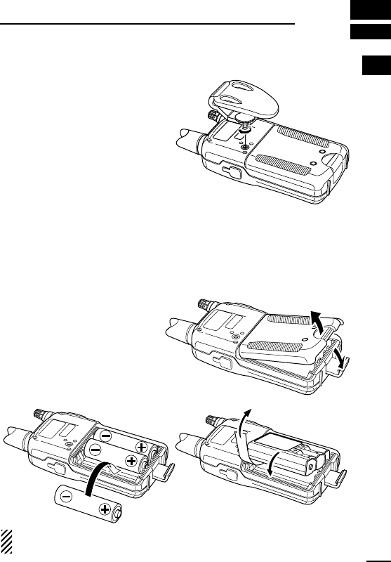
■Belt clip attachment
Attach the belt clip using the
supplied screw. Conveniently
attaches to a belt.
■Battery installation
Install 3 R6 (AA) size alkaline cell batteries or the optional BP-202
BATTERY PACK
as illustrated below.
qRemove the battery case
cover from the transceiver.
wInstall 3×R6 (AA) size alka-
line cell batteries or BP-
202.
• Be sure to observe the cor-
rect polarity.
NOTE: Keep battery contacts clean. It’s good idea to clean bat-
tery terminals once a week.
Alkaline cells
BP-202
IC-4088A_3_Draft.qxd 03.7.16 21:05 Page 1 (1,1)
2
2PANEL DESCRIPTION
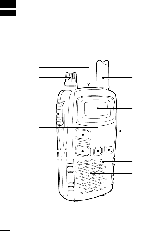
■Switches, controls, keys and
connectors
q
Antenna
Function
display
(p. 4)
Speaker
Microphone
w
e
r
t
y
u
i
IC-4088A_3_Draft.qxd 03.7.16 21:05 Page 2 (1,1)

3
2
PANEL DESCRIPTION
2
qEXTERNAL SPEAKER AND MICROPHONE JACKS
Connect an optional speaker-microphone or headset, if desired.
wVOLUME CONTROL [VOL]
Rotate clockwise to increase and counterclockwise to decrease
volume.
ePTT SWITCH [PTT]
Push and hold to transmit; release to receive.
rMODE SWITCH [MODE]
➥Push to enter and select set mode for group (p. 12) and voice
scrambler code. (p. 16)
➥Push and hold for 1 sec. to turn the monitor function ON and
OFF. (p. 8)
tCHANNEL UP SWITCH [Y]
➥Push to increment the operating channel.
➥Push and hold to increment the operating channel continu-
ously.
➥While scanning, changes scanning direction. (p. 14)
yCHANNEL DOWN SWITCH [Z]
➥Push to decrement the operating channel.
➥Push and hold to decrement the operating channel continu-
ously.
➥While scanning, changes scanning direction. (p. 14)
uPOWER SWITCH [PWR]
➥Push to turn the power ON.
➥Push and hold this key to toggle the key lock function
ON/OFF. (p. 19)
iEXTERNAL DC IN JACK [DC 6V] (p. 6)
Connects the optional AC adapter or cigarette lighter cable for
both operation and battery charging.
IC-4088A_3_Draft.qxd 03.7.16 21:05 Page 3 (1,1)

4
2PANEL DESCRIPTION
■Function display
qKEY LOCK INDICATOR
Appears during the key lock function ON.
wBUSY INDICATOR
Appears while receiving a signal or when the squelch is open.
eVOICE SCRAMBLER INDICATOR
Appears while the voice scrambler function is in use.
rAUTO POWER OFF INDICATOR
Appears while the auto power off function is ON.
tLOW BATTERY INDICATOR
Appears or blinks when the battery decreases to a specified
level.
yGROUP NUMBER INDICATOR
Indicates the selected group number during the group function ON.
uCHANNEL NUMBER INDICATOR
Indicates the selected operating channel number.
iPOWER ON INDICATOR
Appears while the power is ON.
oANSWER BACK INDICATOR
➥Appears when you and your group are in the conversation
area.
➥Blinks when you or your group is out of the conversation area.
!0 TRANSMIT INDICATOR
Appears during PTT ON.
qewrt
yuio
!0
IC-4088A_3_Draft.qxd 03.7.16 21:05 Page 4 (1,1)

5
3
BATTERY CHARGING
2
3
■Battery caution
CAUTION NEVER short the terminals.
NEVER mix old and new batteries.
NEVER incinerate used battery cells. Internal battery gas may
cause explosion.
Make sure all battery cells are the same brand, type and capacity.
AVOID over charging— The BP-202 can be charged during oper-
ation when the AC adapter or the optional cigarette lighter cable is
connected. To prevent over charging, the IC-4088A has charging
timer that automatically disconnecting the charging line electroni-
cally after 15 hours from charging. However, the charging timer will
reset and start charging again when disconnect then re-connecting
the AC adapter or CP-18A more than 1 min. interval.
Recommended temperature range for charging:
+50˚F to +104˚F (+10˚C to +40˚C)
The optional BP-202
BATTERY PACK
includes rechargeable Ni-Cd
batteries and can be charged approx. 300 times. Charge the battery
pack before first operating the transceiver or when the battery pack
becomes exhausted.
If the battery pack seems to have no capacity even after being fully
charged, completely discharge it by leaving the power ON all day.
Then, fully charge the battery pack again.
If the battery pack still does not retain a charge (or very little), a new
battery pack must be purchased.
DDRecycling information (U.S.A. only)
The battery (BP-202) that you have purchased is
recyclable. At the end of its life, under various
state and local laws, it may be illegal to dispose
of this battery into the municipal waste stream.
Call 1-800-822-8837 for battery recycling options
in your area or contact your dealer.
IC-4088A_3_Draft.qxd 03.7.16 21:05 Page 5 (1,1)
6
3BATTERY CHARGING
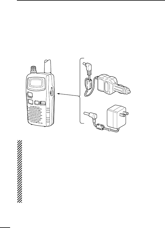
■Charging connections
DDRegular charging with the BC-149A, CP-18A
➥Connect the optional BC-149A
AC ADAPTER
or CP-18A
CIGARETTE
LIGHTER CABLE
to [DC 6V].
•Charging period: approx. 15 hours
IMPORTANT!:
Use the BC-149A or CP-18A ONLY. Other type of AC adapter,
cigarette lighter cable or DC power cable with an external power
supply may damage the transceiver.
The optional BP-202 can only be charged— other AA (R6) size
rechargeable Ni-Cd cannot be charged.
BE SURE to disconnect the CP-18A from the cigarette lighter
socket when charging is finished, because, a slight current still
follows in the CP-18A and the vehicle’s battery will become ex-
hausted.
to [DC 6V]
jack
Optional CP-18A
Cigarette lighter cable
with DC-DC converter
Optional BC-149A
to cigarette
lighter socket
to AC outlet
IC-4088A_3_Draft.qxd 03.7.16 21:05 Page 6 (1,1)
7
3
BATTERY CHARGING
3
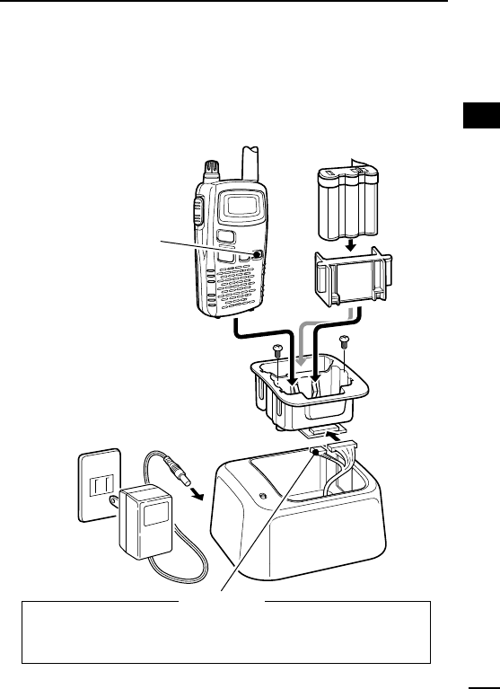
DDRapid charging with the BC-119N+AD-105
qInsert the optional AD-105
DESKTOP CHARGER ADAPTER
into the
charging slot of the BC-119N.
wInsert the battery pack, either by itself or attached to the trans-
ceiver, into the charger.
IC-4088A BP-202
AD-105
BC-119N
AC adapter
NOT used:
Fix the 3-pin connector to the bottom of the charger with the
adhesive tape, etc., to prevent catching or touching the 3-pin
connector’s terminals with the adapter’s leads, etc.
*
*NOTE: Put the Ni-Cd
battery adapter into the
AD-105 rear slot when
the BP-202 is attached
to the transceiver.
Turn the power OFF!
When the installed Ni-Cd
battery is nearly exhausted
and the function display
blinks in intermittently,
push [PWR] until the trans-
ceiver’s power goes OFF.
IC-4088A_3_Draft.qxd 03.7.16 21:05 Page 7 (1,1)
8
4BASIC OPERATION
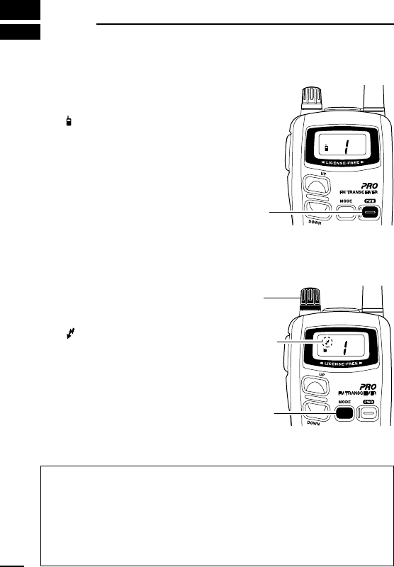
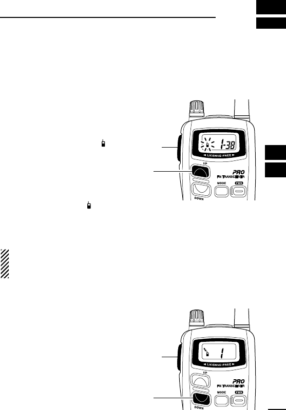
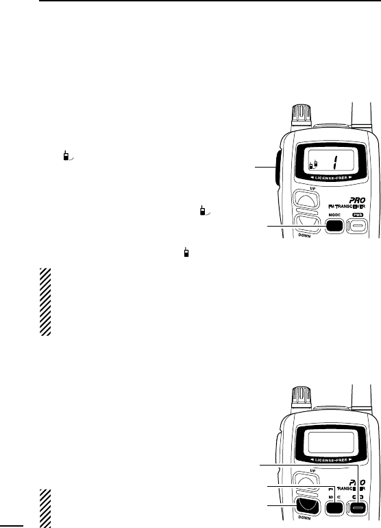
■Power ON
➥Push [PWR] for 1 sec. to turn
the power ON.
•“ ” and operating channel num-
ber appear on the display.
■Adjusting the volume
qPush and hold [MODE] for
1 sec. to open the squelch
(monitor function ON).
•“ ” indicator appears on the dis-
play while the squelch is open.
wAdjust the audio to a suitable
level using [VOL].
ePush and hold [MODE] for
1 sec. to close the squelch.
✔What is squelch?
A squelch circuit allows muting of undesired noise while receiving
no signal and emit audio while receiving signals.
This provides quiet standby. The [MODE] key changes the
squelch setting. This is useful to listen to weak signals that do
not open the squelch.
[PWR]
[MODE]
Appears
[VOL]
IC-4088A_3_Draft.qxd 03.7.16 21:05 Page 8 (1,1)
9
4
BASIC OPERATION
4
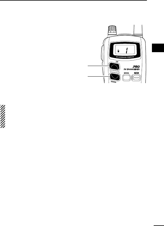
■Selecting the operating channel
Push [Y] or [Z] keys several times
until the desired operating channel
number appears on the display.
•While pushing and holding [Y] or
[Z] keys, the displayed channel
changes continuously until chan-
nel number “1” appears.
To keep the automatic selection,
release the [Y] or [Z] keys then
push and hold them again.
•When displayed channel stops at channel number “1,” a beep is
emitted.
NOTE:
•The transceiver has 14 operating frequency channels.
• The selected channel is memorised when the transceiver is
turned off.
[Y]
[Z]
IC-4088A_3_Draft.qxd 03.7.16 21:05 Page 9 (1,1)
10
5RECEIVE AND TRANSMIT
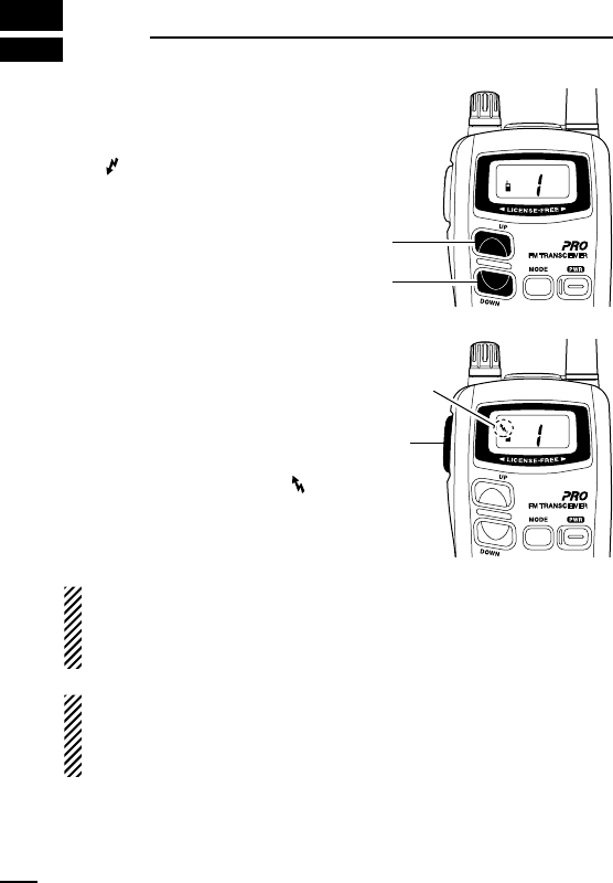
qSelect the desired operating
channel with [Y]/[Z].
When a signal is received:
• “” indicator appears on the
display.
•Squelch opens and audio is
emitted from the speaker.
- Further adjustment of [VOL]
may be necessary at this point.
wPush and hold [PTT] to transmit
then speak into the microphone.
•Do not hold the transceiver too
close to your mouth or speak too
loudly. This may distort the sig-
nal.
•The transmit indicator “” ap-
pears on the display.
eRelease [PTT] to return to re-
ceive.
IMPORTANT:
To maximize the readability of the transmitted signal, pause a
few sec. after pushing [PTT], hold the transceiver 4 to 6 in. (10 to
15 cm) from your mouth and speak at a normal voice level.
NOTE:
The transceiver has an auto power save function to conserve
the battery power. The power save function activates automati-
cally when no signal is received for 5 sec.
[Y]
[Z]
[PTT]
Appears
IC-4088A_3_Draft.qxd 03.7.16 21:05 Page 10 (1,1)

11
5
RECEIVE AND TRANSMIT
5
✔Talk Range
The IC-4088A is designed to maximize performance and improve
transmission range in the field. However, the single most impor-
tant factor in transmit range (talk power) is the surrounding envi-
ronment. These radios are “line of sight” radios and as such,
transmission range are influenced by the degree to which you
can “see” the other communicating party. Large concrete struc-
tures and heavy foliage or transmission from inside a building or
vehicle will reduce the talk power range.
•Optimal range: wide, open areas free of obstructions.
•Medium range: large buildings or trees blocking your line of
sight.
•Minimum range: mountainous areas or areas of heavy foliage.
IC-4088A_3_Draft.qxd 03.7.16 21:05 Page 11 (1,1)
12
6GROUP MODE (CTCSS)
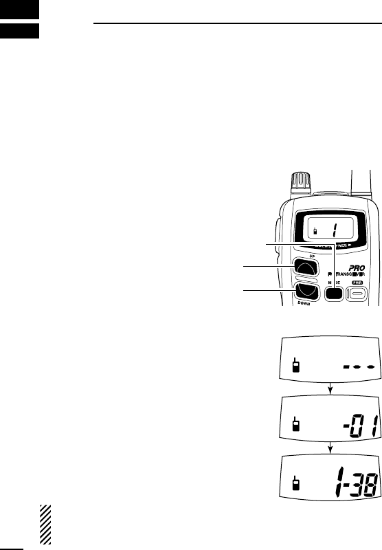
■Setting the group code
The IC-4088A is equipped with 38 group codes. Group mode oper-
ation provides communication with silent standby since you will only
receive calls from group members using the same group number.
First of all, set the same group code number for all group member’s
transceivers.
To turn ON the group mode op-
eration:
q
Push [MODE] to enter set mode.
•“---” (group mode OFF) appears
on the display.
wPush [Y] or [Z] to select the de-
sired code number.
ePush [MODE] twice to set the
group code number and exit set
mode.
To cancel the group mode oper-
ation:
q
Push [MODE] to enter set mode.
•Channel number disappears on
the display.
wPush [Y] or [Z] to select “---”
(group mode OFF).
ePush [MODE] twice to cancel
the group mode and return to
operating condition.
NOTE: Only stations with the same group channel number can
be heard during group mode operation, even when the busy in-
dicator appears on the display.
[Y]
[Z]
[MODE]
IC-4088A_3_Draft.qxd 03.7.16 21:05 Page 12 (1,1)

13
6
GROUP MODE (CTCSS)
6
DDCTCSS code table
(unit: Hz)
CH Freq. CH Freq. CH Freq. CH Freq.
01 67.0 11 97.4 21 136.5 31 192.8
02 71.9 12 100.0 22 141.3 32 203.5
03 74.4 13 103.5 23 146.2 33 210.7
04 77.0 14 107.2 24 151.4 34 218.1
05 79.7 15 110.9 25 156.7 35 225.7
06 82.5 16 114.8 26 162.2 36 233.6
07 85.4 17 118.8 27 167.9 37 241.8
08 88.5 18 123.0 28 173.8 38 250.3
09 91.5 19 127.3 29 179.9 --- OFF
10 94.8 20 131.8 30 186.2
✔What is CTCSS (Continuous Tone Coded Squelch System)
GROUP MODE ?
CTCSS (Continuous Tone Coded Squelch System) GROUP
MODE allows communication with silent stand by. Only signals
containing a specific group code can open the squelch.
This conveniently eliminates unwanted audio and is useful in
group activities or security related activities where unwanted out-
put can be a problem. Note that CTCSS group mode is not pri-
vate—anyone can receive your calls.
The IC-4088A is equipped with 38 tone codes for CTCSS GROUP
MODE use. Selecting a code applies it to all 14 operating chan-
nels. Each push of [PTT] superimposes your group code over your
transmit signal; and, only signals containing the same code can
open your squelch. To temporarily hear all signals (including noise)
push and hold [MODE]. Do not use CTCSS GROUP MODE if you
want to be able to hear signals on all channels.
IC-4088A_3_Draft.qxd 03.7.16 21:05 Page 13 (1,1)
14
7SCAN FUNCTION
Scanning is an efficient way to locate signals quickly over all chan-
nels. Select scan resume condition in advance, using Initial Set
Mode (p. 17)
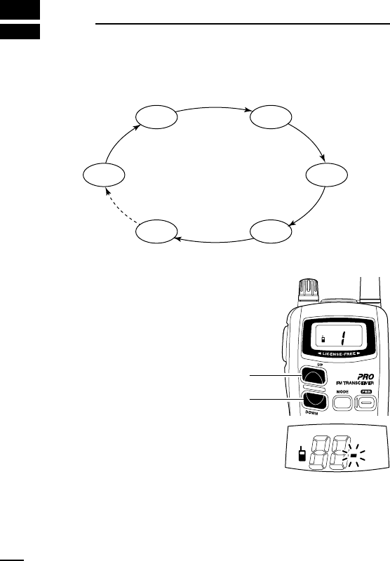
DStarting the scan
➥While pushing [Y], push [Z] to
start the scan.
• “-” flashes.
• While pushing [Z], pushing
[Y] also starts the scan.
• Push [Z] or [Y] to change the
scanning direction or resume
the scan manually.
• To cancel the scan, push [Z]
(or [Y]) while [Y] (or [Z]) is
pushed, or push [PTT].
CH 14 CH 3
CH 2CH 1
CH 4CH 5
[Z]
[Y]
IC-4088A_3_Draft.qxd 03.7.16 21:05 Page 14 (1,1)
15
8
RING FUNCTIONS
7
8
■Smart-Ring
The ring function has an answer back feature. This allows confir-
mation of whether or not a call has reached the receiving party even
if the operator is temporarily away from the transceiver.
qSet the same group channel
number for all of the group
transceivers. (See p. 12)
wWhile pushing [PTT], push [Y] .
•A beep is emitted and “” blinks
on the display.
eRelease the [PTT].
• When a member of a specific
group answers a call, the trans-
ceiver emits beep tones for
10 sec. and blinks “.”
•When no answer comes back, the transceiver emits short faint
beep tones.
rPush [PTT] to answer and to stop the beeps and flashing.
NOTE: This function is available only when the called station has
set the same group number and the same operating channels
as you.
■Call-Ring
Sends the ring tones during trans-
mit mode.
➥While pushing [PTT], push [Z]
to send a ring tone.
•The ring tone is emitted while
pushing [Z].
•The microphone signal is auto-
matically cut while pushing [Z].
[PTT]
[Y]
[PTT]
[Z]
IC-4088A_3_Draft.qxd 03.7.16 21:05 Page 15 (1,1)
16
9OTHER FUNCTIONS
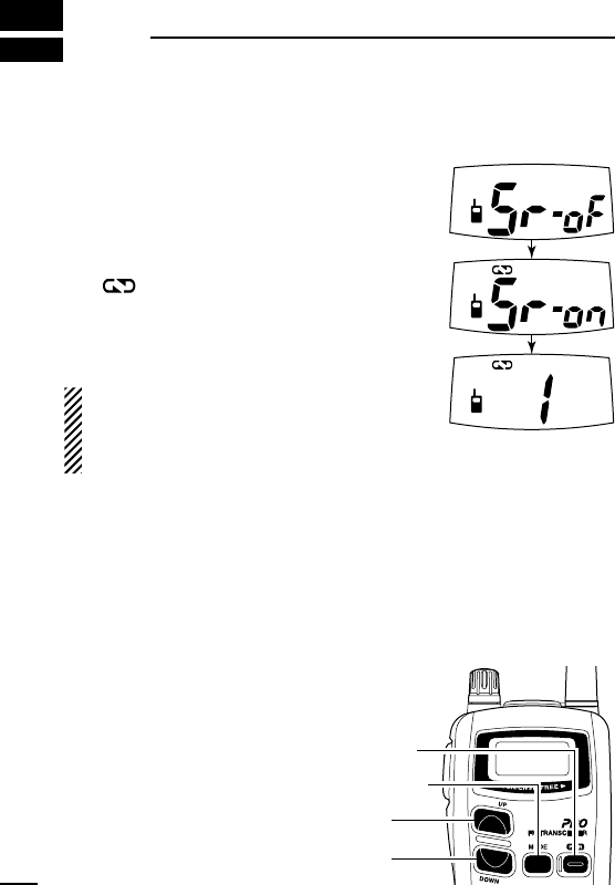
■Voice scrambler function
The voice scrambler function provides communication privacy.
qPush [MODE] twice to select voice scram-
bler setting mode.
•“Sr-” appears on the display.
wPush [Y]/[Z] to turn the function ON and
OFF.
•“ ” appears when the voice scrambler is
activated.
ePush [MODE] to exit voice scrambler set-
ting mode.
NOTE: All transceivers in a specific group
MUST turn ON the voice scrambler func-
tion. Otherwise the communication will not
possible.
■Initial set mode
Initial set mode is accessed at power ON and allows the setting of
seldom changed settings. In this way the user can “customize” trans-
ceiver operations to suit specific preferences and operating style.
DDEntering initial set mode
qWhile pushing [MODE], push
[PWR] for 1 sec. to enter initial
set mode.
wPush [MODE] to select the de-
sired item.
ePush [Y]/[Z] to select the con-
dition or value as desired.
rPush [PWR] to exit initial set
mode.
[Y]
[Z]
[MODE]
[PWR]
IC-4088A_3_Draft.qxd 03.7.16 21:05 Page 16 (1,1)

17
9
9
OTHER FUNCTIONS
DBeep tones ON/OFF
Confirmation beep tones normally sound
when a key is pushed. These can be turned
ON or OFF.
ON (on) : Emits confirmation beep.
OFF (oF) : No confirmation beep.
DDScan resume type
Select the scan resume type from timer scan
and pause scan.
Timer scan (tS) : Scan resumes after the
specified time period even
signal is received.
Pause scan (PS): Scan pauses until the sig-
nal disappears.
DDTime-out timer
The time-out timer limits continuous trans-
mission time period to prevent accidental
prolonged transmission, such as when using
the PTT hold function.
The time period can be specified within
1–30 min. in 1 min. steps.
DDAuto power OFF timer
When signal is received, or no opera-
tion is performed for the set period, the
transceiver turns power OFF automat-
ically.
30 min., 1 and 2 hours timers are
available.
Appears when the auto
power off function is in use.
IC-4088A_3_Draft.qxd 03.7.16 21:05 Page 17 (1,1)
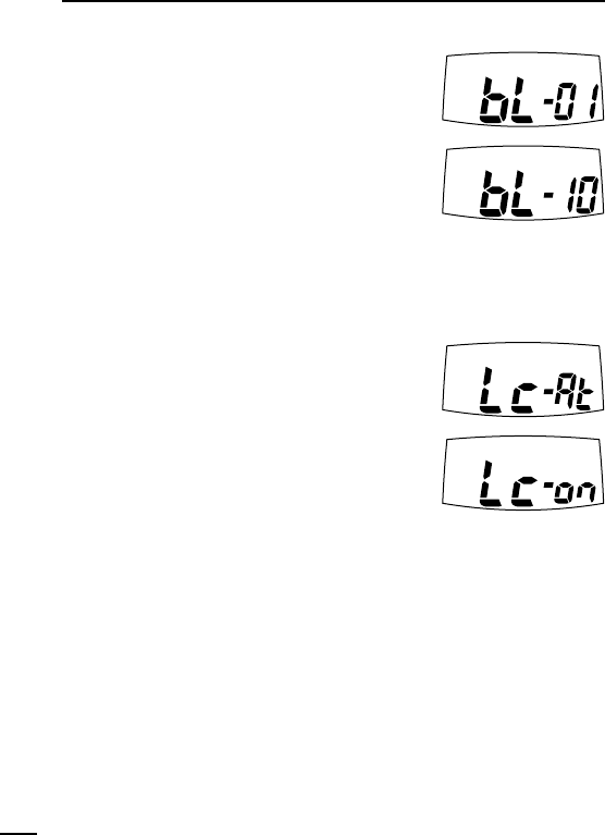
DRing tone type
Ring tone is selectable with 10 different indi-
vidual sounds.
DDLCD backlight
The IC-4088A has LCD backlight light for nighttime operation, and
the lighting condition can be selected to suits a specific preference,
from Auto, ON and OFF.
Auto (At) : Lights when any switch,
except [PTT], is pushed.
When no key operation is
performed for 5 sec., the
backlight goes OFF.
ON (on) : Lights continuously.
OFF (oF) : Never lights.
18
9OTHER FUNCTIONS
IC-4088A_3_Draft.qxd 03.7.16 21:05 Page 18 (1,1)
19
9
9
OTHER FUNCTIONS
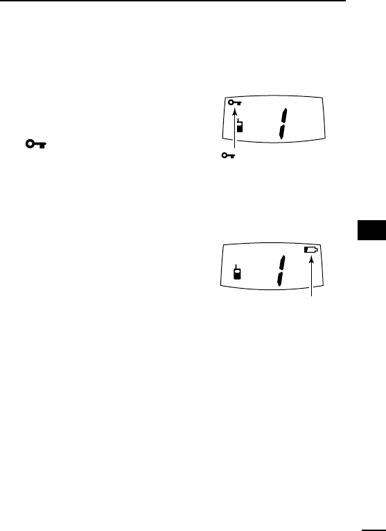
■Lock function
This function electronically locks all keys and switches to prevent
accidental channel changes and function access.
➥Continue to hold [PWR] down for
2 sec. after power ON to turn the lock
function ON and OFF.
•“ ” appears on the display.
- Only [PWR] and [PTT] are functional.
- The Ring function is also available.
(See p. 15)
■Low battery indicator
➥Appears when the battery is nearing
exhaustion.
•A warning beep is emitted while turn-
ing the power ON.
➥Blinks when battery replacement is
necessary.
•When the indicator blinks, the trans-
ceiver may not be operated. (Not
guaranteed)
‘‘Auto power save
➥The power save function reduces the current drain to conserve
battery power.
- The function automatically turns ON when no operation is per-
formed and no signal is received for 5 sec.
“ ” appears when the
lock function is in use.
Appears when the battery
is nearing exhaustion.
Blinks when battery
replacement is necessary.
IC-4088A_3_Draft.qxd 03.7.16 21:05 Page 19 (1,1)
20
9OTHER FUNCTIONS
■ATS (Automatic Transponder System)
This allows the user to confirm whether or not a call has reached
the receiving party even if the operator is temporarily away from the
transceiver. No “Ring” tone is emitted with this function.
➥While pushing [PTT], push
[MODE] to turn the function ON
and OFF.
•“ ” appears on the display.
•The transceiver starts to send a
searching signal every 60 sec.
- When the transceiver receives
an answer back signal, “”
stays on the display until the
next search transmit.
- If no reply is received, “” blinks until the next search transmit.
NOTE: Above setting is for the calling station only. A called party
automatically sends an answer back signal without any preset-
tings. All IC-4088A’s operating on the same operating channel
will answer back to the call in the surroundings communications
area.
‘‘Resetting the transceiver
Initialize the operating conditions
before using the transceiver for the
first time, or if the function display
shows erroneous information.
➥ While pushing [Z] and [MODE],
push [PWR] for 1 sec. to initial-
ize the transceiver.
CAUTION: Resetting the trans-
ceiver returns all settings to
their defaults.
[PTT]
[MODE]
[MODE]
[PWR]
[Z]
IC-4088A_3_Draft.qxd 03.7.16 21:05 Page 20 (1,1)
21
9
OTHER FUNCTIONS
9
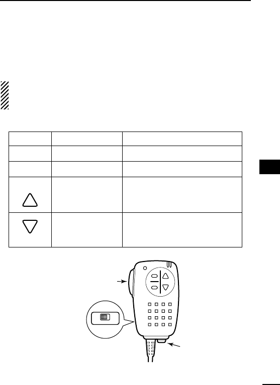
■Optional HM-75A functions
The optional HM-75A allows remotely selected operating channels,
open the squelch, etc. The switches on the HM-75A function as fol-
lows.
CAUTION: When connecting the HM-75A to the transceiver,
make sure that power to the transceiver is turned OFF, other-
wise the transceiver may malfunction.
DSwitch action
SWITCH
A
B
UP
DOWN
NORMAL
Smart-Ring
Open squelch
Change the oper-
ating channel
number up.
Change the oper-
ating channel
number down.
While holding HM-75A’s [PTT]
No function
No function
Smart-Ring
Call-Ring
A
OFF ON
LOCK
B
Lock switch:
Locks all
switches
except [PTT]
Earphone
jack
PTT switch
IC-4088A_3_Draft.qxd 03.7.16 21:05 Page 21 (1,1)

22
10 SPECIFICATIONS
GENERAL
• Frequency coverage : 462.5625–467.7125 MHz
• No. of operating Ch. : 14 (simplex)
• Mode : 11K0F3E (FM)
• Frequency stability : ±2.5 ppm
• Channel separation : 25 kHz
• Power supply requirement : 3 AA (R6) alkaline,BP-202, BC-149A
(negative ground) or CP-18A
•Current drain : Less than 500 mA
• Operating temp. range : –4˚F to +122˚F; –20˚C to +50˚C
•No. of CTCSS freq. : 38
• Dimensions : 21⁄16(W)×41⁄32(H)×11⁄16(D) in
(projections not included) ; 52.5(W)×102.5(H)×26.9(D) mm
• Weight : 200 g; 7 oz (including 3×AA (R6) batteries)
TRANSMITTER
• Output power : Less than 500 mW ERP
• Maximum deviation : ±2.5 kHz
• Spurious emissions : Less than –40 dB
• Ext. mic. connector : 3-conductor 2.5 (d) mm/2.2 kΩ
RECEIVER
• Receiver system : Double-conversion superheterodyne
•Sensitivity (12 dB SINAD) : Less than 0.2 µV
• Selectivity : More than 8.5 kHz/–6dB
•
Spurious & image rejection
: More than 40 dB
• Adjacent Ch. rejection : More than 40 dB
• Intermodulation rejection : More than 40 dB
• Audio output power : More than 100 mW at 10 % distortion
(at 4.5 V DC) with an 8 Ωload
•Ext. speaker connector : 3-conductor 3.5 (d) mm/8 Ω
All stated specifications are subject to change without notice or obligation.
IC-4088A_3_Draft.qxd 03.7.16 21:06 Page 22 (1,1)

23
10
SPECIFICATIONS
10
DChannel number and group number
Use this page to record a group operating channel number (see
p. 9) and group code number (p. 12) for your reference.
ïChannel frequency list
Operating channel number
Group code number
CH Freq.(MHz)
1 462.5625
2 462.5875
3 462.6125
4 462.6375
5 462.6625
6 462.6875
7 462.7125
8 467.5625
9 467.5875
10 467.6125
11 467.6375
12 467.6625
13 467.6875
14 467.7125
IC-4088A_3_Draft.qxd 03.7.16 21:06 Page 23 (1,1)

24
11 OPTIONS
BP-202 Ni-Cd BATTERY PACK
3.6V/700 mAh Ni-Cd battery pack.
BC-119N
DESKTOP CHARGER
+ AD-105
DESKTOP CHARGER ADAPTER
Rapidly charges battery pack in 1 to 1.5 hrs. An AC adapter is packed with
the BC-119N. The AD-105 must be used with the BC-119N for charging the
battery pack. The CP-17L or OPC-515L can be used instead of the supplied
AC adapter. (p. 7)
BC-149A
AC ADAPTER
Regularly charges installed BP-202 in 15 hours (approx.). Operation for both
transmit and receive also possible with this adapter.
Output voltage: 6 V DC, Current capacity: 1 A
CP-18A
CIGARETTE LIGHTER CABLE
Allows you to operate the transceiver through a 12 V cigarette lighter socket,
and also charges the installed battery regularly. A DC-DC converter is built-in.
HM-46/HM-75A/HM-131
SPEAKER MICROPHONES
HM-46: Compact size with transmission LED indicator.
HM-75A: Remote control capability. (See p. 21 for details.)
HM-131: Compact and durable construction.
HM-128
EARPHONE MICROPHONE
HS-85
HEADSET
Over-head arm style headset. VOX and one-touch PTT functions are avail-
able.
VS-1
VOX
/
PTT CASE
+ HS-94/HS-95/HS-97
Separated VOX/PTT unit and one of the following microphone unit is re-
quired additionally.
HS-94 Earhook type HS-95 Neck-arm type HS-97 Throat microphone
IC-4088A_3_Draft.qxd 03.7.16 21:06 Page 24 (1,1)

25
12
MEMO
11
12
IC-4088A_3_Draft.qxd 03.7.16 21:06 Page 25 (1,1)

1-1-32 Kamiminami, Hirano-ku, Osaka 547-0003 Japan
A-6274D-1US-w
Printed in Japan
© 2003 Icom Inc.
IC-4088A_3_Draft.qxd 03.7.16 21:06 Page 26 (1,1)