ICOM orporated 263300 VHF/UHF Amateur Transceiver User Manual
ICOM Incorporated VHF/UHF Amateur Transceiver Users Manual
UserManual.wiki
>
ICOM orporated
>
263300 User Manual
Users Manual
Navigation menu
Upload a User Manual
Namespaces
Wiki Guide
HTML
PDF
Info
Views
User Manual
Discussion / Help
Navigation
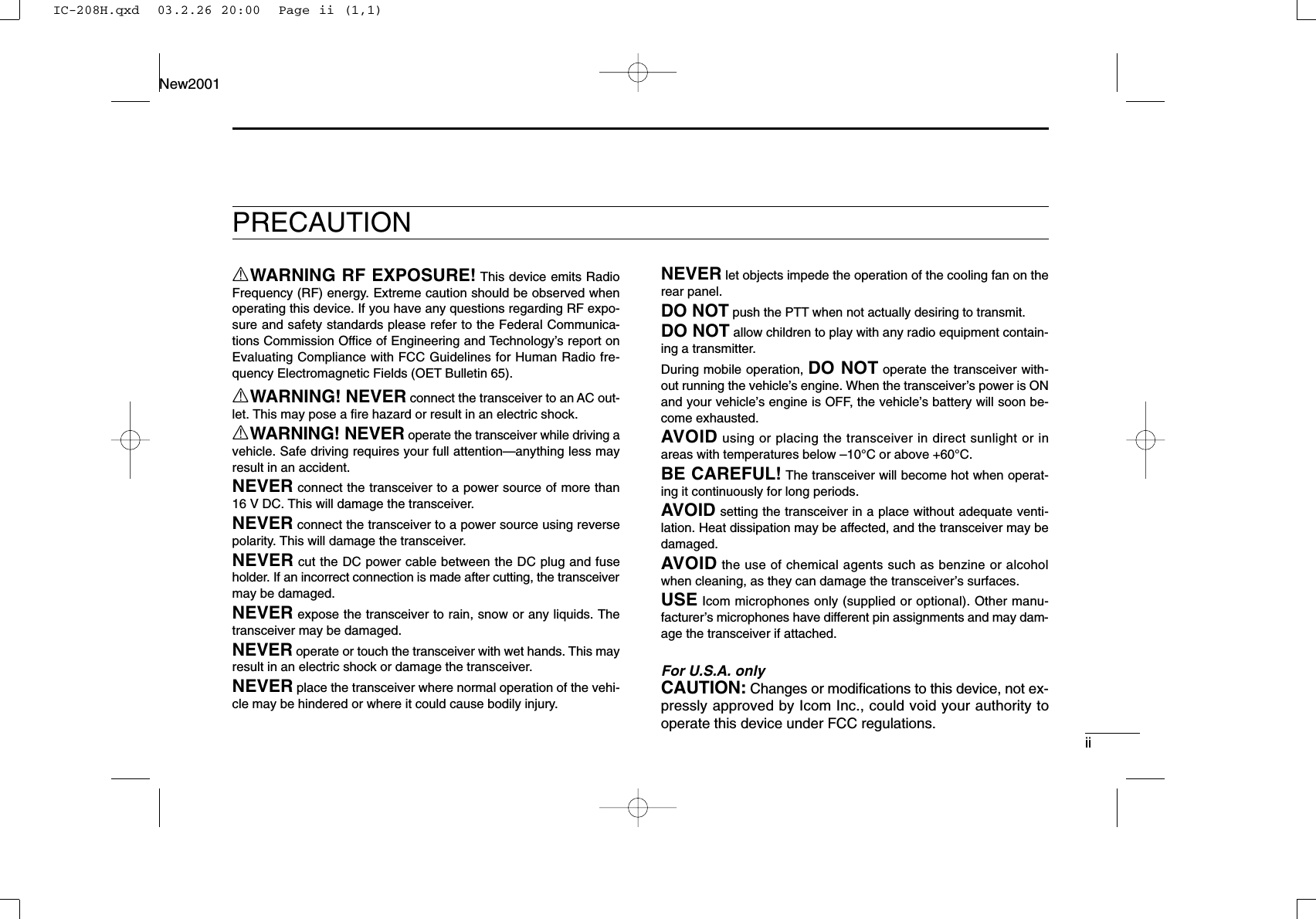
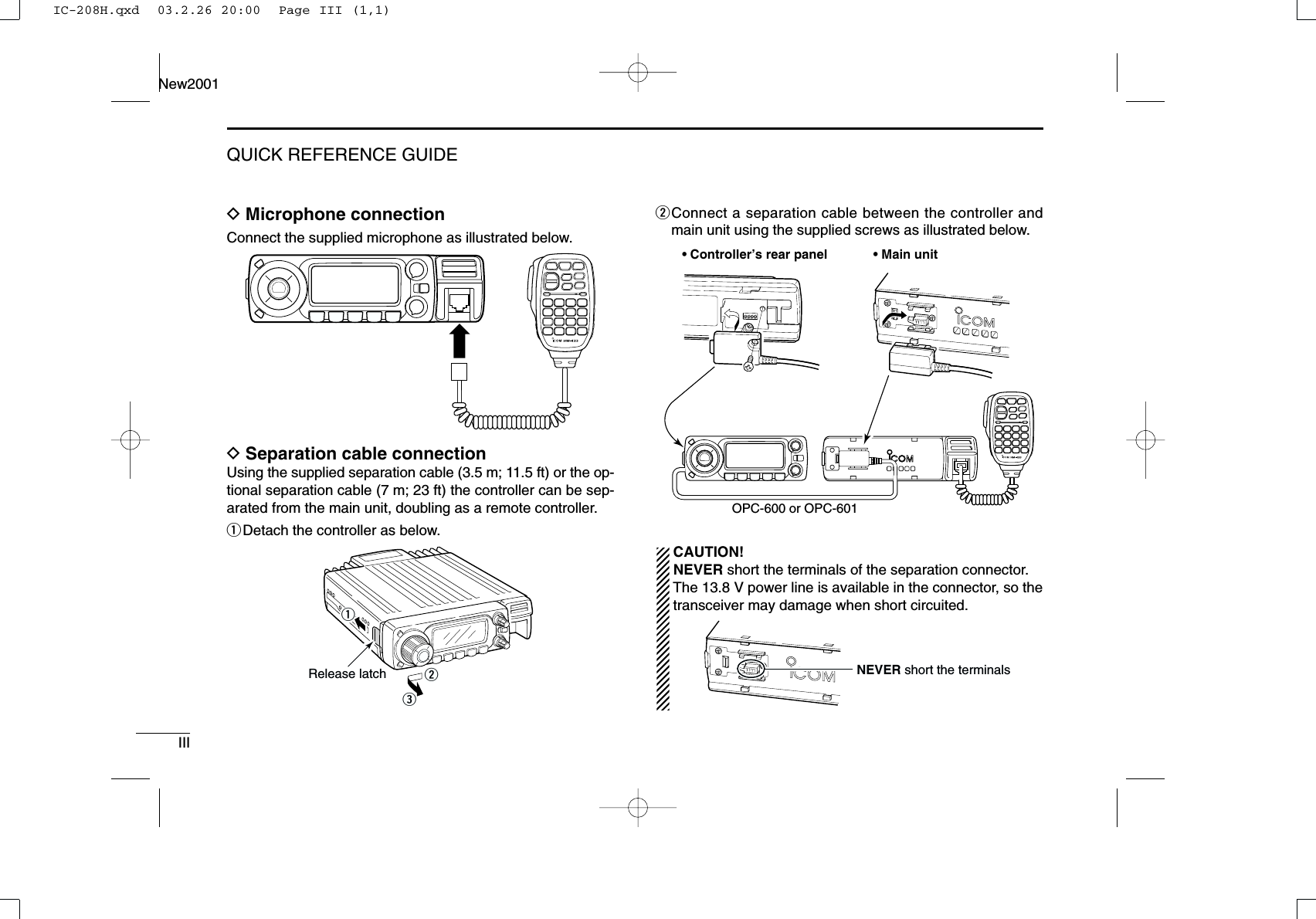
![New2001iiiTABLE OF CONTENTSSUPPLIED ACCESSORIESqDC power cable (3 m) ………………………………………1wMobile mounting bracket …………………………………1eMicrophone (HM-133)* ……………………………………1rFuse (20 A) …………………………………………………1tMounting screws, nuts and washers …………………1 setyMicrophone hanger …………………………………………1uSeparation cable†(3.5 m; 11.5 ft) …………………………1*HM-118N HAND MICROPHONEor HM-118TN/TAN DTMF MICROPHONEsupplied versions are also available.†A ferrite core is adapted for the USA version.qwertyuFOREWORD ........................................................................................... iIMPORTANT ............................................................................................ iEXPLICIT DEFINITIONS ......................................................................... iPRECAUTION ........................................................................................ iiSUPPLIED ACCESSORIES .................................................................. iiiTABLE OF CONTENTS ......................................................................... iiiQUICK REFERENCE GUIDE ............................................................. I–X■Installation ....................................................................................... I■Your first contact .......................................................................... VII■Repeater operation ....................................................................... IX■Programming memory channels..................................................... X1 PANEL DESCRIPTION ............................................................... 1–10■Front panel— controller ................................................................. 1■Function display ............................................................................. 3■Main unit ........................................................................................ 5■Microphone (HM-133) .................................................................... 7■Microphone keypad ........................................................................ 8■Optional microphones (HM-118N/TN/TAN)................................... 102 SETTING A FREQUENCY ........................................................ 11–14■Preparation ................................................................................... 11■Using the tuning dial .................................................................... 12■Using the [Y]/[Z] keys ................................................................. 12■Using the keypad ......................................................................... 12■Tuning step selection ................................................................... 13■Lock functions .............................................................................. 143 BASIC OPERATION ................................................................. 15–18■Receiving ..................................................................................... 15■Monitor function ........................................................................... 15■Squelch attenuator ....................................................................... 16■Transmitting ................................................................................. 17■Selecting output power ................................................................ 17IC-208H.qxd 03.2.26 20:00 Page iii (1,1)](https://usermanual.wiki/ICOM-orporated/263300/User-Guide-319595-Page-4.png)
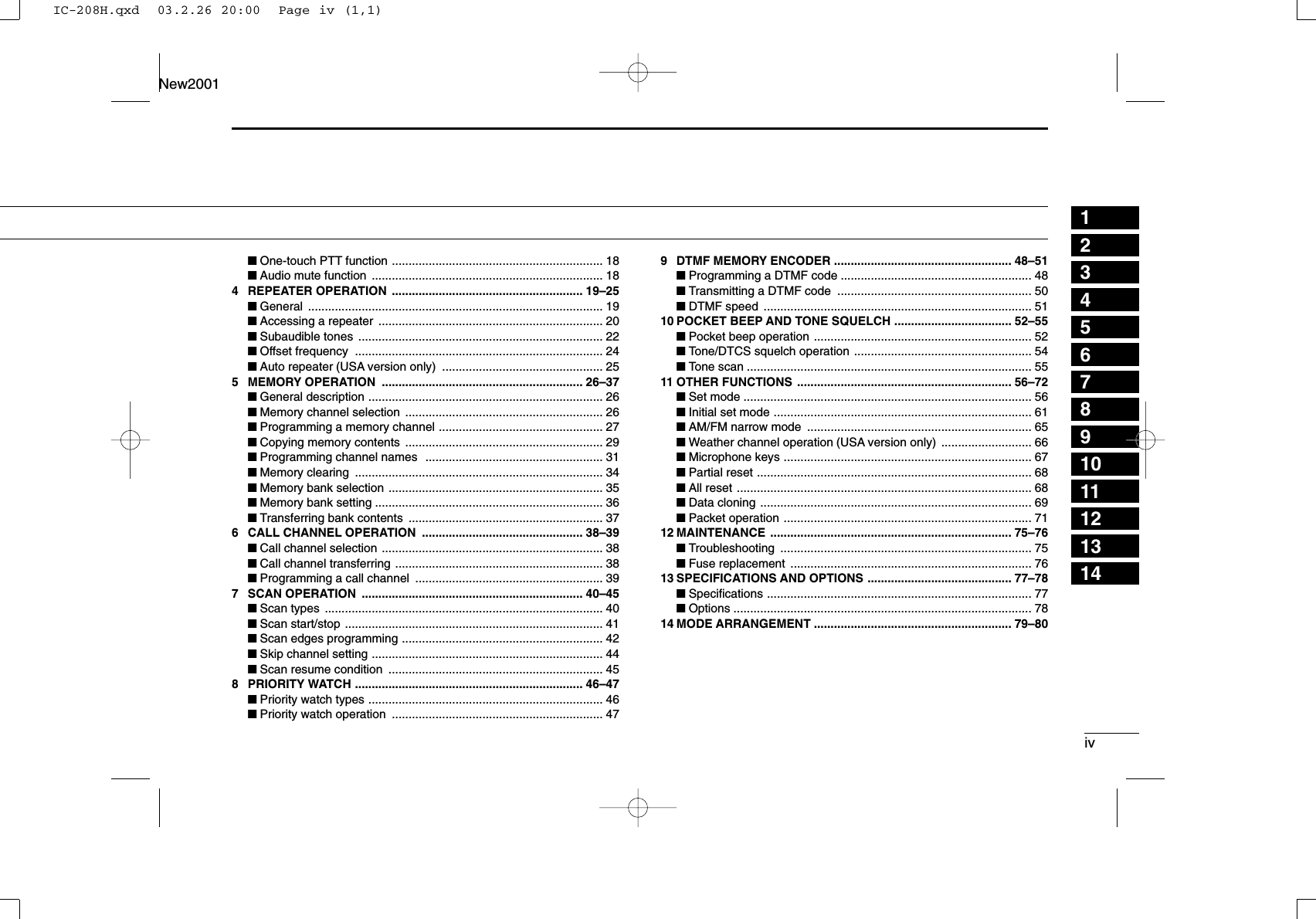
![VIIQUICK REFERENCE GUIDENew2001■Your first contactNow that you have your IC-208H installed in your car orshack, you are probably excited to get on the air. We wouldlike to take you through a few basic operation steps to makeyour first “On The Air” an enjoyable experience. 1. Turning ON the transceiverBefore powering up your IC-208H, you may want to makesure the audio volume and squelch level controls are set in9–10 o’clock positions.Although you have purchased a brand new transceiver, somesettings may be changed from the factory defaults becauseof the QC process. Resetting the CPU is necessary to startfrom factory default.➥While pushing both [SET•LOCK] and [S.MW•MW], push[PWR] for 1 sec. to reset the CPU.2. Selecting the operating frequency bandThe IC-208H has 2 m and 70 cm bands. ➥Push [BAND] to select the desired frequency band.Using the HM-133You can select the main band from the HM-133.PushPush againPush [BAND] to select the desired frequency band.[BAND][PWR]While pushing [SET•LOCK] and [S.MW•MW], turn power ON.[SET•LOCK][S.MW•MW][VOL]Set [VOL] and [SQL] controls to 9–10 o’clock positions.[SQL]IC-208H.qxd 03.2.26 20:00 Page VII (1,1)](https://usermanual.wiki/ICOM-orporated/263300/User-Guide-319595-Page-12.png)
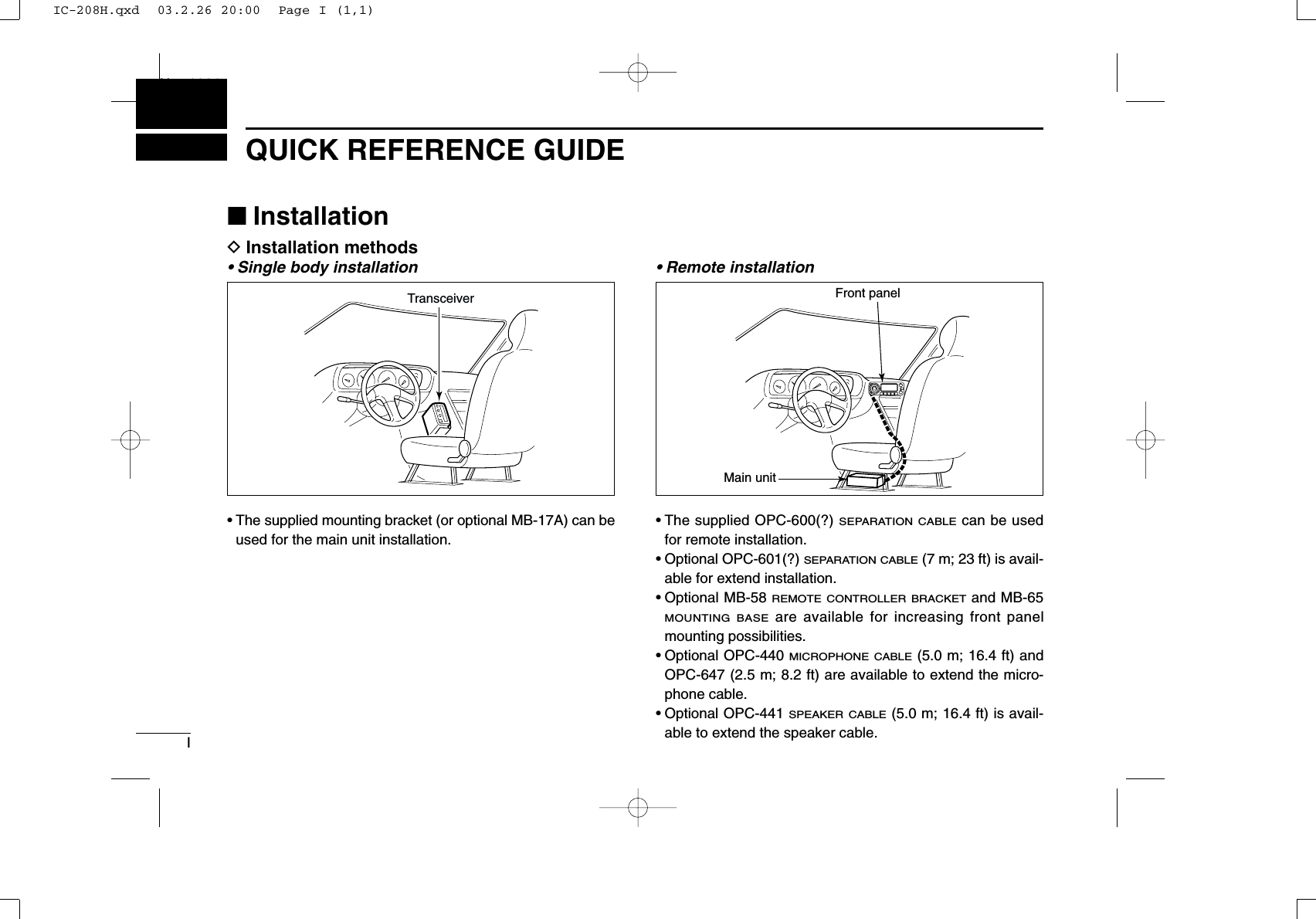
![VIIIQUICK REFERENCE GUIDENew20013. Tune the frequencyThe tuning dial will allow you to dial in the frequency you wantto operate. Pages ?? and ?? will instruct you on how to setthe tuning speed.Using the HM-133You can directly enter the frequency with the HM-133 keypadfor the main band. [EXAMPLE]: Setting frequency to 145.3625 MHz.PushPushPushPushRotate [DIAL] to tune the frequency.[DIAL]Quick reference guideIC-208H.qxd 03.2.26 20:00 Page VIII (1,1)](https://usermanual.wiki/ICOM-orporated/263300/User-Guide-319595-Page-13.png)
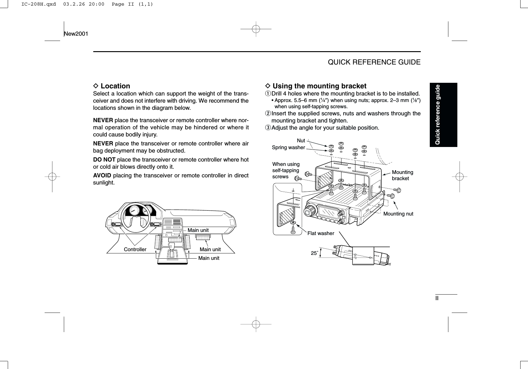
![IXQUICK REFERENCE GUIDENew2001■Repeater operation1. Setting duplex Push [BAND] to select the frequency band.Push [LOW•DUP] for 1 sec. once or twice to select minus du-plex or plus duplex.•The USA version has an auto repeater function, therefore, settingduplex is not required.2. Repeater tone Push [TONE•T-SCAN] several times until “T” appears, if therepeater requires a subaudible tone to be accessed.Using the HM-133Plus or minus duplex selection and the repeater tone settingcan be made easily via HM-133.Push [DUP–7(TONE)] for minus duplex; [DUP+8(TSQLS)]for plus duplex selection, push [FUNC] then [DUP–7(TONE)]to turn the repeater tone ON.PushPush , then Push[TONE•T-SCAN][LOW•DUP]IC-208H.qxd 03.2.26 20:00 Page IX (1,1)](https://usermanual.wiki/ICOM-orporated/263300/User-Guide-319595-Page-14.png)
![XQUICK REFERENCE GUIDENew2001Quick reference guide■Programming memory channelsThe IC-208H has a total of 512 memory channels (including10 scan edges and 2 call channels) for storing often used op-erating frequency, repeater settings, etc. 1. Setting a frequencyIn VFO mode, set the desired operating frequency with re-peater, tone and tuning steps, etc. ➥Push [V/MHz•SCAN] to select VFO.➥Rotate [DIAL] to set the desired frequency.•Set other data, such as repeater tone, duplex information, tuningstep), if desired.2. Selecting a memory channel Push [S.MW•MW], then rotate [DIAL] to select the desiredmemory channel.•“!” indicator and memory channel number blink.3. Writing a memory channelPush and hold [S.MW•MW] for 1 sec. to program.•3 beeps sound•Return to VFO mode automatically after the program.•Memory channel number automatically increases when continuingto push [S.MW•MW] after programming.Using the HM-133qIn VFO mode, set the desired operating frequency, includ-ing offset direction, tone settings, etc.➥Push [VFO/LOCK] to select VFO.➥Push [ENTC(T-OFF)] first, then enter the desired oper-ating frequency via the keypad.•Set other data, such as repeater tone, duplex information,tuning step, if necessary.wPush [FUNC] then [CLRA(MW)].•“!” indicator and memory channel number blink.ePush [Y]/[Z] to select the desired memory channel.rPush [FUNC] then push [CLRA(MW)] for 1 sec. to pro-gram.•3 beeps sound•Memory channel number automatically increases when continu-ing to push [CLRA(MW)] after programming.Push , then [S.MW•MW]IC-208H.qxd 03.2.26 20:00 Page X (1,1)](https://usermanual.wiki/ICOM-orporated/263300/User-Guide-319595-Page-15.png)
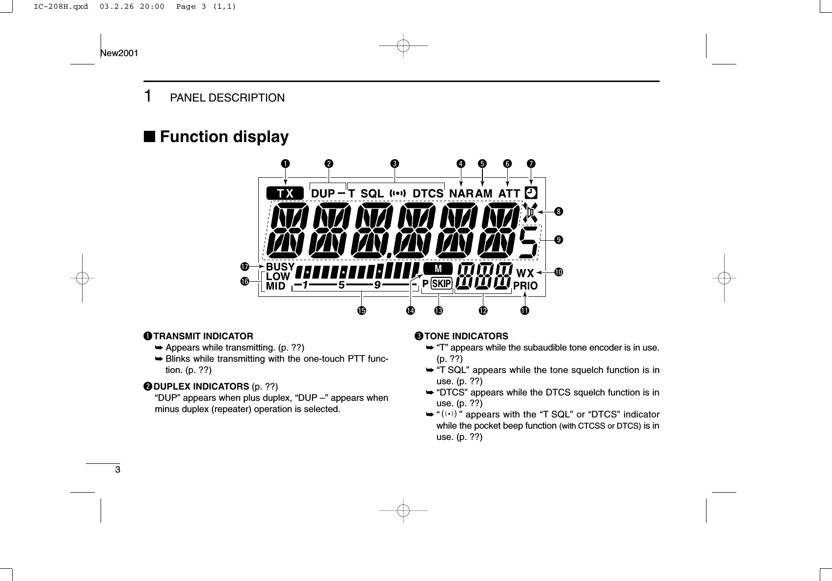
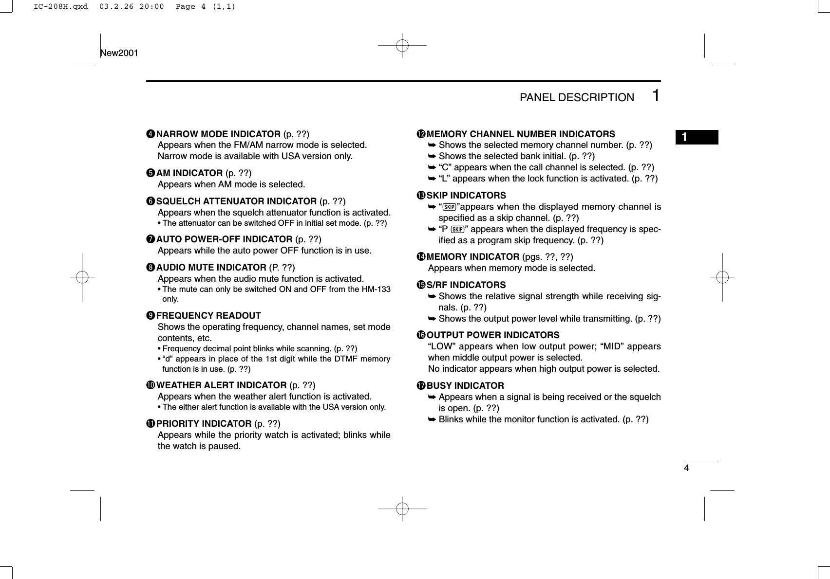
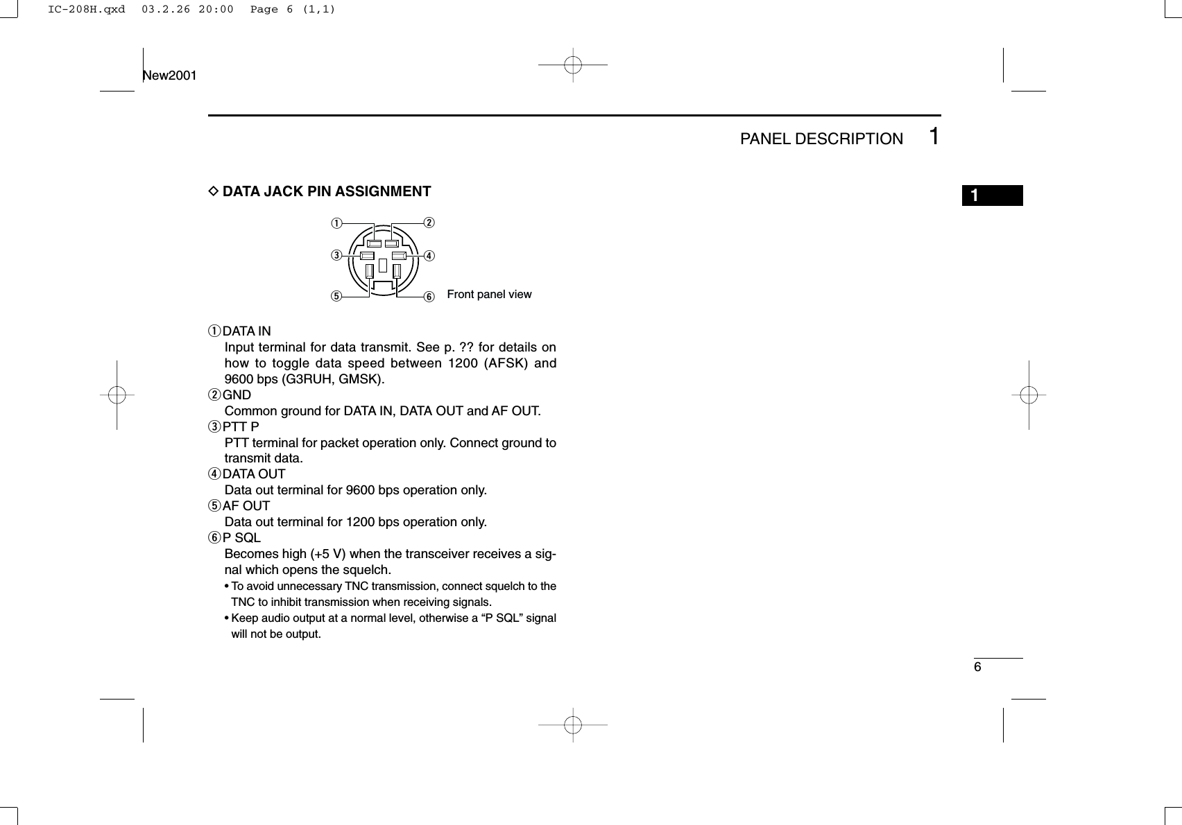
![■Front panel— controllerqSET•LOCK SWITCH [SET•LOCK]➥Enters set mode when pushed. (p. ??)➥Switches the lock function ON and OFF when pushedfor 1 sec. (p. ??)wTUNING DIAL [DIAL]Selects the operating frequency (p. ??), memory channel(p. ??), the setting of the set mode item and the scanningdirection (p. ??).eVOLUME CONTROL [VOL] (p. ??)Adjusts the audio level for relative band.rPOWER SWITCH [PWR]Turns power ON and OFF when pushed for 1 sec.tMICROPHONE CONNECTOR (p. ??)Connects the supplied microphone.q+8 V DC output (Max. 10 mA)wChannel up/downe8 V control INrPTTtGND (microphone ground)yMIC (microphone input)uGNDiData INqiq w Function display (p. 3) e rtyuio!0!1!2!31PANEL DESCRIPTIONNew20011IC-208H.qxd 03.2.26 20:00 Page 1 (1,1)](https://usermanual.wiki/ICOM-orporated/263300/User-Guide-319595-Page-16.png)
![21PANEL DESCRIPTIONNew20011ySQUELCH CONTROL [SQL]Varies the squelch level. (p. ??)•The RF attenuator activates and increases the attenuation whenrotated clockwise to the center position and further. (p. ??)uMONITOR•DTMF SWITCH [MONI•DTMF]➥Push to switch the monitor function ON and OFF. (p. 00)➥Turns DTMF memory encoder ON and OFF whenpushed for 1 sec. (p. ??)iOUTPUT POWER•DUPLEX SWITCH [DUP•DUP]➥Each push changes the output power selection. (p. ??)➥Push for 1 sec. to select DUP–, DUP+ and simplex op-eration. (p. ??)oTONE•TONE SCAN SWITCH [TONE•T-SCAN]➥Each push selects a tone function. (pgs. ??, ??)•Subaudible tone encoder, pocket beep (CTCSS), tonesquelch, pocket beep (DTCS), DTCS squelch or tone func-tion OFF can be selected.➥Push for 1 sec. to starts the tone scan. (p. ??)!0MEMORY/CALL•PRIORITY SWITCH [M/CALL•PRIO]➥Push to select and toggle memory, call and weatherchannel* modes. (pgs. ??, ??, ??, ??)*Weather channels available for USA versions only.➥Starts priority watch when pushed for 1 sec. (p. ??)!1VFO/MHz TUNING•SCAN SWITCH [V/MHz•SCAN]➥Selects and toggles VFO mode and 1 MHz (or 10 MHzfor some versions) tuning when pushed. (p. ??)➥Starts scan when pushed for 1 sec. (p. ??)•Cancels a scan when pushed during scan.!2BAND SWITCH [BAND]➥Push to select the operating frequency band. (p. ??)➥Push to select the call channel during call channel op-eration. (p. ??)➥Push for 1 sec. to select the operating mode. (p. ??)!3MEMORY WRITE SWITCH [S.MW•MW]➥Selects a memory channel for programming whenpushed. (pgs. ??, ??, ??)➥Programs the selected memory channel when pushedfor 1 sec. (pgs. ??, ??, ??)!4CONTROLLER RELEASE LATCHWhile pushing this latch, slide the controller to the left toremove it.!4IC-208H.qxd 03.2.26 20:00 Page 2 (1,1)](https://usermanual.wiki/ICOM-orporated/263300/User-Guide-319595-Page-17.png)
![51PANEL DESCRIPTIONNew2001■Rear PanelqDATA SOCKET [DATA]Connects a TNC (Terminal Node Controller), etc. for datacommunications.•See p. ? for connection information.wEXTERNAL SPEAKER JACK 1 [SP]Connects an 8 Ωspeaker.•Audio output power is more than 2.4 W.eCOOLING FAN Rotates while transmitting. Also rotates while receiving depending on the setting in ini-tial set mode. (p. ??)rANTENNA CONNECTOR [ANT]Connects a 50 Ωantenna with a PL-259 connector and a50 Ωcoaxial cable.tPOWER RECEPTACLE [DC13.8V]Accepts 13.8 V DC ±15% with the supplied DC powercable.☞NOTE: DO NOT use a cigarette lighter socket as apower source when operating in a vehicle. The plugmay cause voltage drops and ignition noise may be su-perimposed onto transmit or receive audio.ANTENNA INFORMATIONFor radio communications, the antenna is of critical impor-tance, to maximize your output power and receiver sensi-tivity. The transceiver accepts a 50 Ωantenna and lessthan 1:1.5 of Voltage Standing Wave Ratio (VSWR). HighSWR values not only may damage the transceiver but alsolead to TVI or BCI problems.qwretIC-208H.qxd 03.2.26 20:00 Page 5 (1,1)](https://usermanual.wiki/ICOM-orporated/263300/User-Guide-319595-Page-20.png)
![71PANEL DESCRIPTIONNew2001■Microphone (HM-133*)qVFO/LOCK SWITCH [VFO/LOCK]➥Push to select VFO mode. (p. ??)➥Push for 1 sec. to switch the lock function ON and OFF.(p. ??)wPTT SWITCH➥Push and hold to transmit; release to receive.➥Switches between transmitting and receiving while theone-touch PTT function is in use. (p. ??)eUP/DOWN SWITCHES [Y]/[Z]➥Push either switch to change operating frequency,memory channel, set mode setting, etc. (pgs. ??, ??, ??)➥Push either switch for 1 sec. to start scanning. (p. ??)rACTIVITY INDICATOR➥Lights red while any key, except [FUNC] and [DTMF-S],is pushed, or while transmitting.➥Lights green while the one-touch PTT function is in use.tKEYPAD (pgs. ?, ?)yFUNCTION INDICATOR➥Lights orange while [FUNC] is activated—indicates thesecondary function of switches can be accessed.➥Lights green when [DTMF-S] is activated—DTMF sig-nals can be transmitted with the keypad.u2nd FUNCTION SWITCH [FUNC] iDTMF SELECT SWITCH [DTMF-S] (p. ??)oFUNCTION SWITCHES [F-1]/[F-2] (p. ??)Program and recall your desired transceiver conditions.!0BAND SWITCH [BAND] ➥Push to select the frequency band. (p. ??)➥Push for 1 sec. to select the operating mode. (p. ??)!1MEMORY/CALL SWITCH [MR/CALL]➥Push to select memory mode. (p. ??)➥Push for 1 sec. to select call channel. (p. 38)✔Important!All keys on the microphone function for the main band only. Mic elementqertwyuio!0!1*A different microphonemay be supplied de-pending on version.IC-208H.qxd 03.2.26 20:00 Page 7 (1,1)](https://usermanual.wiki/ICOM-orporated/263300/User-Guide-319595-Page-22.png)
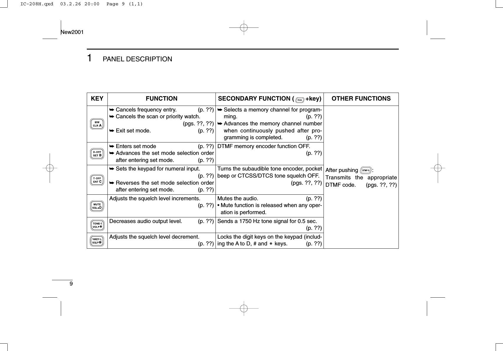
![81PANEL DESCRIPTIONNew20011■Microphone keypadKEY FUNCTION SECONDARY FUNCTION ( +key) OTHER FUNCTIONSSwitches between opening and closing thesquelch. (p. ??)Starts and stops scanning. (p. ??)Starts and stops priority watch. (p. ??)Selects high output power. (p. ??)Selects mid. output power. (p. ??)Selects low output power (p. ??)Selects minus duplex operation. (p. ??)Selects plus duplex operation. (p. ??)Selects simplex operation. (p. ??)Increases audio output level. (p. ??)In memory mode enters bank selectingcondition. (p. ??)Starts and stops tone scanning. (p. ??)Turns the one-touch PTT function ON andOFF. (p. ??)Turns the DTCS squelch ON. (p. ??)Turns the DTCS pocket beep function ON.(p. ??)Turns the DTMF memory encoder functionON. (p. ??)Turns the subaudible tone encoder ON.(p. ??)Turns the CTCSS pocket beep functionON. (p. ??)Turns the tone squelch function ON.(p. ??)Sends a 1750 Hz tone signal while pushingand holding. (p. ??)After pushing :Transmits the appropriateDTMF code. (pgs. ??, ??)When the DTMF memory en-coder is activated, push [0] to[9] to transmit the appropriateDTMF memory contents .(p. ??)IC-208H.qxd 03.2.26 20:00 Page 8 (1,1)](https://usermanual.wiki/ICOM-orporated/263300/User-Guide-319595-Page-23.png)
![101PANEL DESCRIPTIONNew20011■Optional Microphones(HM-118N/TN/TAN)qPTT SWITCH➥Push and hold to transmit; release to receive.wUP/DOWN SWITCHES [UP]/[DN]➥Push either switch to change operating frequency,memory channel, set mode setting, etc. (pgs. ??, ??, ??)➥Push either switch for 1 sec. to start scanning. (p. ??)eUP/DN LOCK SWITCHSlide to toggle [UP]/[DN] switches function ON and OFF.rKEYPAD (HM-118TN/TAN only)While pushing [PTT], push the desired key to send theDTMF code.wqONOFFewrqONOFFe• HM-118N• HM-118TN/TAN (DTMF)IC-208H.qxd 03.2.26 20:00 Page 10 (1,1)](https://usermanual.wiki/ICOM-orporated/263300/User-Guide-319595-Page-25.png)
![11SETTING A FREQUENCYNew20012■PreparationDTurning power ON/OFF➥Push [PWR] for 1 sec. to turn power ON and OFF.DOperating frequency band selectionThe IC-208H has 2 m and 70 cm bands for transmission andreception. In addition, extra frequency bands 127, 220, 350,500 and 900 MHz bands are available for wide-band receivercapability (except Taiwan and Korean version).➥Push [BAND] to select the desired frequency band.➥Push [BAND] to select the desired band.DVFO and memory modesThe transceiver has 2 basic operating modes: VFO mode andmemory mode. Select VFO mode first to set an operating fre-quency.➥Push [V/MHz•SCAN] to select VFO mode.•When VFO mode is already selected, the digit below 10 MHz(the digit below 1 MHz or 100 kHz disappear depending on ver-sions) disappear. In this case, push [V/MHz•SCAN] again (ortwice or 3 times depending on version).➥Push [M/CALL•PRIO] to select memory mode.•“!” indicator appears when memory mode is selected.➥Push [VFO/LOCK] to select VFO mode.➥Push [MR/CALL] to select memory mode.VFO/LOCK[V/MHz•SCAN][M/CALL•PRIO] AppearsBAND[BAND][PWR]Note that in this manual, sections beginning with a micro-phone icon (as above), designate operation via the HM-133microphone.IC-208H.qxd 03.2.26 20:00 Page 11 (1,1)](https://usermanual.wiki/ICOM-orporated/263300/User-Guide-319595-Page-26.png)
![122SETTING A FREQUENCYNew20012■Using the tuning dialqRotate [DIAL] to set the frequency.•If VFO mode is not selected, push [V/MHz•SCAN] to select VFOmode.•The frequency changes in the selected tuning steps. (p. ??)wTo change the frequency in 1 MHz (10 MHz for some versions)steps, push [V/MHz•SCAN], then rotate [DIAL].•Pushing [V/MHz•SCAN] for 1 sec. starts scan function. If scanstarts, push [V/MHz•SCAN] again to cancel it.■Using the [Y]/[Z] keys➥Push [Y] or [Z] to select the desired frequency.•Pushing [Y]/[Z] for 1 sec. activates a scan. If scanstarts, push [Y]/[Z] or [CLRA(MW)] to cancel it.■Using the keypadThe frequency can be directly set via numeral keys on the mi-crophone.zPush [VFO/LOCK] to select VFO mode, if neces-sary.xPush [ENTC(T-OFF)] to activate the keypad fordigit input.cPush 6 keys to input a frequency.•When a digit is mistakenly input, push [ENTC(T-OFF)]to clear the input, then repeat input from the 1st digit.•Pushing [CLRA(MW)] clears input digits and retrievesthe frequency.PushPushPushPush[EXAMPLE]: Setting frequency to 145.3625 MHz.ENTCYZWhile 1 MHz tuning step is selected, the digit below 100 kHz disappear.While 10 MHz tuning step is selected, the digit below 1 MHz disappear.[DIAL][V/MHz•SCAN]IC-208H.qxd 03.2.26 20:00 Page 12 (1,1)](https://usermanual.wiki/ICOM-orporated/263300/User-Guide-319595-Page-27.png)
![132SETTING A FREQUENCYNew2001■Tuning step selection[Tuning steps are the minimum frequency change incrementswhen you rotate [DIAL] or push [Y]/[Z] on the microphone.Independent tuning step for each frequency bands can be setfor individual tuning convenience. The following tuning stepsare available.•5 kHz •10 kHz •12.5 kHz •15 kHz•20 kHz •25 kHz •30 kHz •50 kHz•100 kHz •200 kHz☞NOTE: For convenience, select a tuning step that matchesthe frequency intervals of repeaters in your area.qPush [BAND] to select the desired frequency band.•Push [V/MHz•SCAN] to select VFO mode, if necessary.wPush [SET•LOCK] to enter set mode.ePush [SET•LOCK] or [S.MW•MW] several times until “TS”appears as shown below.rRotate [DIAL] to select the desired tuning step.tPush [V/MHz•SCAN] to exit set mode.zPush [BAND] to select the desired frequencyband.•Push [VFO/LOCK] to VFO mode, if necessary.xPush [SETB(D-OFF)] to enter set mode.cPush [SETB(D-OFF)] or [ENTC(T-OFF)] severaltimes until “tS” appears.vPush [Y] or [Z] to select the desired tuning step.bPush [CLRA(MW)] to exit set mode.SETB[SET•LOCK]IC-208H.qxd 03.2.26 20:00 Page 13 (1,1)](https://usermanual.wiki/ICOM-orporated/263300/User-Guide-319595-Page-28.png)
![142SETTING A FREQUENCYNew20012■Lock functionsTo prevent accidental frequency changes and unnecessaryfunction access, use the lock function. The transceiver has 2different lock functions.DFrequency lockThis function locks [DIAL] and switches electronically and canbe used together with the microphone lock function.➥Push [SET•LOCK] for 1 sec. to turn the lock function ONand OFF.•[PTT], [MONI•DTMF] (monitor function only), [VOL] and [SQL]only) can be used while the channel lock function is in use. Also,TONE-1, TONE-2, DTMF tones or DTMF memory contents canbe transmitted from the microphone.➥Push [VFO/LOCK] for 1 sec. to switch thelock function ON and OFF.DMicrophone keypad lockThis function locks the microphone keypad.➥Push [FUNC] then [SQLZD(16KEY-L)] toswitch the microphone keypad lock functionON and OFF.•[PTT], [VFO/LOCK], [MR/CALL], [BAND], [Y], [Z],[F-1], [F-2] and [FUNC] on the microphone can beused.•All switches on the transceiver can be used.•The keypad lock function is released when thepower is turned OFF then ON again.16KEY-LVFO/LOCK[SET•LOCK]“L” appearsIC-208H.qxd 03.2.26 20:00 Page 14 (1,1)](https://usermanual.wiki/ICOM-orporated/263300/User-Guide-319595-Page-29.png)
![15BASIC OPERATIONNew20013■ReceivingqSet the audio level.➥Push [MONI•DTMF] to open the squelch.➥Rotate [VOL] to adjust the audio level.➥Push [MONI•DTMF] to close the squelch.wSet the squelch level.➥Rotate [SQL] fully counterclockwise in advance, then ro-tate [SQL] clockwise until the noise just disappears.•When interference is received, rotate [SQL] clockwise againfor attenuator operation. (p. ??)eSet the operating frequency. (pgs. ??–??)rWhen receiving a signal on the set frequency, squelchopens and the transceiver emits audio.•“BUSY” appears and the S/RFindicator shows the relativesignal strength for the re-ceived signal.✔CONVENIENT!The audio and squelch level can also be adjustedwith [VOLY(TONE-1)]/[VOLZ0(TONE-2)] and[SQLYD(MUTE)]/[SQLZ#(16KEY-L)], respectively.•“VOL” for audio or “SQL” for squelch appears during set.■Monitor functionThis function is used to listen to weak signals without disturb-ing the squelch setting. ➥Push [MONI•DTMF] to open the squelch.•“BUSY” blinks.•Push [MONI•DTMF] again to cancel the function.➥Push [MONI1(BANK)] to open the squelch.•Push [MONI1(BANK)] again to cancel the function.NOTE: When [SQL] adjustment is set too far clockwise,(12–5 o’clock position) the squelch attenuator is activated.To monitor weak signals on the operating frequency, deac-tivate the squelch attenuator function. See p. ?? for details.MONI1[MONI•DTMF] BlinksShow set levelSQLY/ZD/#VOLY/ZM/0Appears when receiving a signalIC-208H.qxd 03.2.26 20:00 Page 15 (1,1)](https://usermanual.wiki/ICOM-orporated/263300/User-Guide-319595-Page-30.png)
![163BASIC OPERATIONNew20013■Squelch attenuatorThe transceiver has an RF attenuator related to the squelchlevel setting. Approx. 10 dB attenuation is obtained at maxi-mum setting. The squelch attenuator allows you to set a minimum signallevel needed to open the squelch. The attenuator function canbe deactivated in initial set mode.➥Rotate [SQL] clockwise past the 12 o’clock position to ac-tivate the squelch attenuator.•Attenuation level can be adjusted up to 10 dB (approx.) between12 o’clock and fully clockwise position.•When setting the squelch from the microphone, a level greaterthan ‘19’activates the squelch attenuator.NOTE: The squelch attenuator functions even when themonitor function is in use. Thus set [SQL] control within 10to 12 o’clock position is recommended when using themonitor function.DSquelch attenuator settingqTurn the transceiver power OFF.wWhile pushing [SET•LOCK], turn the power ON to enter ini-tial set mode.ePush [SET•LOCK] or [S.MW•MW] to select “ATT” (squelchattenuator) item.rRotate [DIAL] to toggle the function ON and OFF.•Select “OF” to deactivate the squelch attenuator function.tPush [PWR] to exit initial set mode.[PWR][SET•LOCK]USINGINITIAL SET MODESquelch isopen.SquelchattenuatorSquelch threshold Shallow DeepNoise squelchIC-208H.qxd 03.2.26 20:00 Page 16 (1,1)](https://usermanual.wiki/ICOM-orporated/263300/User-Guide-319595-Page-31.png)
![173BASIC OPERATIONNew2001■Transmitting☞NOTE: To prevent interference, listen on the channel be-fore transmitting by pushing [MONI•DTMF] on the frontpanel or [MONI1(BANK)] on the microphone.qSelect the frequency band. (p. ??)wSet the operating frequency. (pgs. ??–??)•Select output power if desired. See section at right for details.ePush and hold [PTT] to transmit.•“$” appears.•The S/RF indicator shows the output power selection.•A one-touch PTT function is available. See p. ?? for details.rSpeak into the microphone using your normal voice level.•DO NOT hold the microphone too close to your mouth or speaktoo loudly. This may distort the signal.tRelease [PTT] to return to receive.■Selecting output powerThe transceiver has 3 output power levels to suit your oper-ating requirements. Low output powers during short-distancecommunications may reduce the possibility of interference toother stations and will reduce current consumption.➥Push [LOW•DUP] once or twice to select the output power.†50 W for Korean version; *approx •The output power can be changed while transmitting.The microphone can also be used to select output power.➥Push [HIGH4(DTCS)] for high output power;[MID5(DTCSS)] for middle output power; and[LOW6(DTMF)] for low output power.•The output power can be changed via the microphoneduring receive only.HIGH4MID5LOW6IMPORTANT! (for 55/50 W transmission):The IC-208H is equipped with protection circuit to protectthe power amplifier circuit from high SWR (Standing WaveRatio) and temperature. When a high SWR antenna or noantenna is connected, or when the transceiver temperaturebecomes extremely high, the transceiver reduces transmitoutput power to 15 W (approx.) automatically. CAUTION: Transmitting without an antenna will damagethe transceiver.S/RF INDICATOR POWER OUTPUTVHF/UHF Taiwan55 W†/50 W 25 W15 W*/15 W* 15 W*5 W*/5 W* 5 W*High:Mid:Low:IC-208H.qxd 03.2.26 20:00 Page 17 (1,1)](https://usermanual.wiki/ICOM-orporated/263300/User-Guide-319595-Page-32.png)
![■One-touch PTT functionThe PTT switch can be operated as a one-touch PTT switch(each push toggles between transmit/receive). Using thisfunction you can transmit without pushing and holding thePTT switch.To prevent accidental, continuous transmissions with thisfunction, the transceiver has a time-out timer. See p. ?? fordetails.zPush [FUNC] then [PRIO3(PTT-M)] to turn theone-touch PTT function ON.•The activity indicator lights green.xPush [PTT] to transmit and push again to re-ceive.•A beep sounds when transmission is started and along beep sounds when returning to receive.•“$” blinks when transmitting with the one-touchPTT function.cPush [FUNC] then [PRIO3(PTT-M)] to turn theone-touch PTT function OFF.•The activity indicator goes out.■Audio mute functionThis function temporarily mutes the audio without disturbingthe volume setting.➥Push [FUNC] then [SQLYD(MUTE)] to muteaudio signals.•The audio mute indicator, “” appears.•Push [CLRA(MW)] (or any other key) to cancel thefunction.AppearsMUTEindicator blnksPTT-M183BASIC OPERATIONNew20013IC-208H.qxd 03.2.26 20:00 Page 18 (1,1)](https://usermanual.wiki/ICOM-orporated/263300/User-Guide-319595-Page-33.png)
![204REPEATER OPERATIONNew20014■Accessing a repeaterqSet the receive frequency (repeater output frequency).(pgs. ??–??)wPush [LOW•DUP] for 1 sec. one or two times, to selectminus duplex or plus duplex.•“DUP–” or “DUP” appears to indicate the transmit frequency forminus shift or plus shift, respectively.•When the auto repeater function is turned ON (available for theUSA version only), steps wand eare not necessary. (p. ??)ePush [TONE•T-SCAN] several times to turn ON the sub-audible tone encoder, according to repeater requirements.•“T” appears •88.5 Hz is set as the default; refer to p. ?? for tone frequencysettings.•When the repeater requires a different tone system, see p. ??.rPush and hold [PTT] to transmit.•The displayed frequency automatically changes to the transmitfrequency (repeater input frequency).•If “OFF” appears, confirm that the offset frequency (p. ??) is setcorrectly.tRelease [PTT] to receive.yPush [MONI•DTMF] to check whether the other station’stransmit signal can be received directly.uTo return to simplex operation, push [LOW•DUP] once ortwice, to clear the “DUP–” or “DUP” indicator.iTo turn OFF the subaudible tone encoder, push [TONE•T-SCAN] several times until no tone indicators appear.While transmittingWhile receiving[TONE•T-SCAN] “T” appears[LOW•DUP] “DUP–” or “DUP” appearsIC-208H.qxd 03.2.26 20:00 Page 20 (1,1)](https://usermanual.wiki/ICOM-orporated/263300/User-Guide-319595-Page-35.png)
![214REPEATER OPERATIONNew2001zSet the receive frequency (repeater output fre-quency). (pgs. ??–??)xPush [DUP–7(TONE)] to select minus duplex;push [DUP+ 8(TSQLS)] to select plus duplex.cPush [FUNC] then [DUP–7(TONE)] to turn ONthe subaudible tone encoder according to re-peater requirements.•Refer to p. ?? for the tone frequency setting.•When the repeater requires a different tone system,see p. ??.vPush and hold [PTT] to transmit.bRelease [PTT] to receive.nPush [MONI1(BANK)] to check whether theother station’s transmit signal can be receiveddirectly.mPush [SIMP9(TSQL)] to return to simplex opera-tion.•“DUP” or “DUP–” indicator disappears.,To turn OFF the subaudible tone encoder, push[FUNC] then [ENTC(T-OFF)].SIMP9Push ,then .PushPushDUP–7DUP+8IC-208H.qxd 03.2.26 20:00 Page 21 (1,1)](https://usermanual.wiki/ICOM-orporated/263300/User-Guide-319595-Page-36.png)
![224REPEATER OPERATIONNew20014■Subaudible tones [(Encoder function)DSubaudible tonesqSelect the frequency band, mode/channel you wish to setthe subaudible tones to, such as VFO mode ormemory/call channel.wPush [SET•LOCK] to enter set mode.ePush [SET•LOCK] or [DUP•MONI] several times until “T”and “rT” appear; or until “T SQL” and “CT” appear for tonesquelch or pocket beep use.•When “d” is displayed in place of the 100 MHz digit, cancel theDTMF memory encoder in advance. (p. ??)rRotate [DIAL] to select and set the desired subaudible fre-quency.tPush [V/MHz•SCAN] to exit set mode.☞NOTE: The subaudible tone encoder frequency can be setin a memory/call channel temporarily. However, the set fre-quency is cleared once another memory channel or VFOmode is selected. To store the tone frequency permanently,overwrite the channel information.zSet the frequency band, mode/channel you wishto set the subaudible tones to, such as VFOmode or memory/call channel.•The subaudible tone frequency is independently pro-grammed into each mode or channel.xPush [SETB(D-OFF)] to enter set mode.cPush [SETB(D-OFF)] or [ENTC(T-OFF)] severaltimes until “T”and “rT” appears; or until “T SQL”and “CT” appears for tone squelch or pocketbeep use.•When “d” is displayed in place of the 100 MHz digit,cancel the DTMF memory encoder in advance. (p. ??)vPush [Y] or [Z] to select and set the desiredsubaudible tone frequency.•Push and hold [Y]/[Z] to change the above tonescontinuously.bPush [CLRA(MW)] to exit set mode.•Subaudible tone frequency list (unit: Hz)67.069.371.974.477.079.782.585.488.591.594.897.4100.0103.5107.2110.9114.8118.8123.0127.3131.8136.5141.3146.2151.4156.7159.8162.2165.5167.9171.3173.8177.3179.9183.5186.2189.9192.8196.6199.5203.5206.5210.7218.1225.7229.1233.6241.8250.3254.1Push SETB[SET•LOCK] “T” and “rT” appearsIC-208H.qxd 03.2.26 20:00 Page 22 (1,1)](https://usermanual.wiki/ICOM-orporated/263300/User-Guide-319595-Page-37.png)
![DDTMF tones➥Push [DTMF-S], then push the keys of the de-sired DTMF digits.•The function indicator lights green.•0–9, A–D, M(E) and #(F) are available.•When “d” is displayed in place of the 100 MHz digit,cancel the DTMF memory encoder in advance.(p. 50)•Push [DTMF-S] again to return the keypad to nor-mal function control.✔For your convenient!The transceiver has 16 DTMF memory channels for au-topatch operation. See p. ?? for details.D1750 Hz toneThe microphone has 1750 Hz tone capability, used for ringtone when calling, etc.zPush [FUNC].•The function indicator lights orange.xPush [MM(TONE-1)] to transmit a 1750 Hz tonecall signal for 0.5 sec.; push and hold[0(TONE-2)] to transmit a 1750 Hz tone callsignal for an arbitrary period.•The function indicator goes out automatically.Push ,then or .TONE-1TONE-2then push desired keys.Push ,DTMF-S234REPEATER OPERATIONNew2001IC-208H.qxd 03.2.26 20:00 Page 23 (1,1)](https://usermanual.wiki/ICOM-orporated/263300/User-Guide-319595-Page-38.png)
![244REPEATER OPERATIONNew20014■Offset frequency [When communicating through a repeater, the transmit fre-quency is shifted from the receive frequency by an amountdetermined by the offset frequency. Independent offset frequencies can be set for each operatingfrequency.qPush [BAND] to select the desired frequency band.wSelect the desired mode/channel you wish to set the offsetfrequency to, such as VFO mode or memory/call channel.•The offset frequency can be independently programmed intoeach mode or channel.ePush [SET•LOCK] to enter set mode.rPush [SET•LOCK] or [S.MW•MW] until “DUP” and offsetfrequency appear.tRotate [DIAL] to set the desired offset frequency.yPush [V/MHz•SCAN] to exit set mode.zPush [BAND] to select the desired frequencyband.•Enter the desired frequency via the keypad if neces-sary.xSelect the desired mode/channel you wish toset the offset frequency to, such as VFO modeor memory/call channel.•The offset frequency can be independently pro-grammed into each mode or channel.cPush [SETB(D-OFF)] to enter set mode.vPush [SETB(D-OFF)] or [ENTC(T-OFF)] until“DUP” and offset frequency appear.bPush [Y] or [Z] to set the desired offset.•Direct frequency entry from the keypad is not possi-ble.nPush [CLRA(MW)] to exit set mode.☞NOTE: The offset frequency can be set in a memory/callchannel temporarily. However, the set frequency is clearedonce another memory channel or VFO mode is selected.To store the offset frequency permanently, overwrite thechannel information.Push SETB[SET•LOCK] “DUP” and offset frequency appearIC-208H.qxd 03.2.26 20:00 Page 24 (1,1)](https://usermanual.wiki/ICOM-orporated/263300/User-Guide-319595-Page-39.png)
![■Auto repeater (U.S.A. version only)The USA version automatically activates the repeater settings(DUP– or DUP+ and tone encoder ON/OFF) when the operatingfrequency falls within the general repeater output frequencyrange and deactivate them when outside of the range.DSetting the auto repeater function ON/OFFqPush [PWR] to turn power OFF.wWhile pushing [SET•LOCK], turn power ON to enter initialset mode.ePush [SET•LOCK] or [S.MW•MW] several times until the“RPT” display appears as shown above right.rRotate [DIAL] to select the auto repeater function from“R1,” “R2” or OFF.•“R1”: auto repeater is ON, tone encoder is OFF.•“R2”: auto repeater is ON, tone encoder is ON.tPush [PWR] to exit initial set mode.DFrequency range and offset directionAuto DUP: ONAuto tone set: OFFAuto DUP: ONAuto tone set: ON[PWR][SET•LOCK]USINGINITIAL SET MODE254REPEATER OPERATIONNew2001Frequency range Duplex direction145.200–145.495 MHz “DUP–” appears146.610–146.995 MHz147.000–147.395 MHz “DUP” appears442.000–444.995 MHz “DUP” appears447.000–449.995 MHz “DUP–” appearsIC-208H.qxd 03.2.26 20:00 Page 25 (1,1)](https://usermanual.wiki/ICOM-orporated/263300/User-Guide-319595-Page-40.png)
![265MEMORY OPERATION45■General descriptionThe transceiver has 512 memory channels including 10 scanedge memory channels (5 pairs), and 2 call channels. Each ofthese channels can be individually programmed with operat-ing frequency (pgs. ??–??), duplex direction (p. ??) and off-set (p. ??), subaudible tone encoder or tone squelch and itstone frequency (pgs. ??, ??, ??, ??) and skip information*(p. ??). In addition, a total of 10 memory banks, A to J, are availablefor usage by group, etc.*except for scan edge memory channels.■Memory channel selectionDUsing the tuning dialqPush [M/CALL•PRIO] several times to select memorymode.•“!” indicator appearswRotate [DIAL] to select the desired memory channel.•Programmed memory channels only can be selected.DUsing the [Y]/[Z] keyszPush [MR/CALL] to select memory mode.xPush [Y] or [Z] to select and set the desiredmemory channel.•Pushing [Y]/[Z] for 1 sec. activates a scan.•If scan is activated, push [Y]/[Z] again or push[CLRA(MW)] to stop it.DUsing the keypadzPush [MR/CALL] to select memory mode.xPush [ENTC(T-OFF)] to activate the keypadfor numeral input.cPush 3 appropriate digit keys to input a chan-nel number. •Blank channel can be selected.•Push only 1 appropriate digit key, [MONI1(BANK)],[SCAN2(T-SCAN)], [PRIO3(PTT-M)],[HIGH4(DTCS)] or [MID5(DTCSS)] then push[MM(TONE-1)] or [SQLZ#(16KEY-L)] to select scanedge channels. “MM” and “#” can be used for “A”and “b” respectively.MR/CALLMR/CALLY/Z[M/CALL•PRIO] “!” appearsIC-208H.qxd 03.2.26 20:00 Page 26 (1,1)](https://usermanual.wiki/ICOM-orporated/263300/User-Guide-319595-Page-41.png)
![275MEMORY OPERATIONNew2001■Programming a memory channel[EXAMPLE]: Programming 145.870 MHz into memory channel 20 (blank channel) via the controller.Push Rotate for setting frequency, etc. Push .Rotate Push for 1 sec. and continue to push ➠Beep“BeepBeepBeep“““““Beep“VFO settings, including the set mode contents such as sub-audible tone frequency, offset, can be programmed into amemory channel.qSet the desired frequency. ➥Push [V/MHz•SCAN] to select VFO mode.➥Set the frequency using [DIAL].➥Set other data (e.g. tone frequency, duplex information,etc.) if required.wPush [S.MW•MW].•“!” indicator and the memory channel number blink.eRotate [DIAL] to select the memory channel to be pro-grammed.•Memory channels not yet programmed are blank.rPush [S.MW•MW] for 1 sec. to program.•3 beeps sound•Memory channel number automatically increases when contin-uing to push [M/CALL•MW] after programming.✔CONVENIENTMemory programming can be performed in versatile wayse.g. memory channel to the same (or different) memory chan-nel, memory channel to the call channel, etc.IC-208H.qxd 03.2.26 20:00 Page 27 (1,1)](https://usermanual.wiki/ICOM-orporated/263300/User-Guide-319595-Page-42.png)
![285MEMORY OPERATIONNew20015DProgramming a memory channel via the microphone[EXAMPLE]: Programming 145.870 MHz into memory channel 20 (blank channel) via the microphone.Push 10 timesBeep“Beep“BeepBeepBeep“““““Push Push thenPush then for 1 sec. and continue to push ➠The microphone can also be used to program mem-ory channels.zSet the desired frequency in VFO mode.➥Push [VFO/LOCK] to select VFO mode.➥Set the frequency using the keypad.➥Set other data (e.g. offset frequency, duplex direction, sub-audible tone encoder ON/OFF and its frequency), if neces-sary.xPush [FUNC] then [CLRA(MW)] momentarily.cPush [Y] or [Z] to select the memory channel.•Direct numeral input cannot be used.vPush [FUNC] then [CLRA(MW)] for 1 sec. to program.➥3 beeps may sound and the VFO contents (includingthe subaudible tone frequency, etc.) are programmed.➥Memory channel number increases when continuing topush [CLRA(MW)] after programming.MWIC-208H.qxd 03.2.26 20:00 Page 28 (1,1)](https://usermanual.wiki/ICOM-orporated/263300/User-Guide-319595-Page-43.png)
![295MEMORY OPERATIONNew2001■Copying memory contentsThis function copies a memory channel’s contents to VFO (oranother memory/call channel). This is useful when searchingfor signals around a memory channel frequency and for re-calling the offset frequency, subaudible tone frequency etc.DMemory/call➪VFOqSelect the desired memory or call channel.➥Push [M/CALL•PRIO] several times to select memorymode or call channel, then rotate [DIAL] to select the de-sired memory or call channel.wPush [S.MW•MW] for 1 sec. to transfer the selected mem-ory/call channel contents to the VFO.•VFO mode is selected automatically.zSelect the memory/call channel to betransferred.➥Push [MR/CALL] to select memory mode,then select the desired memory channelvia [Y]/[Z] or keypad.➥Push [MR/CALL] for 1 sec. then push[Y]/[Z] to select the call channel.xPush [FUNC], then [CLRA(MW)] for 1 sec. totransfer the selected memory/call channelcontents to the VFO.•VFO mode is selected automatically.MR/CALLMW[Y]/[Z][EXAMPLE]: Transferring memory channel 30 contents to VFO.Push to select memory mode.Front panel operation:HM-133 operation:Push to select memory mode.Rotate for selecting memory channel.Select memory channel.Push for 1 sec.Push then push for 1 sec.IC-208H.qxd 03.2.26 20:00 Page 29 (1,1)](https://usermanual.wiki/ICOM-orporated/263300/User-Guide-319595-Page-44.png)
![305MEMORY OPERATIONNew20015DMemory/call➪call/memoryqSelect the memory/call channel to be transferred.➥Push [M/CALL•PRIO] several times to select memorymode or call channel, then rotate [DIAL] to select thedesired memory or call channel.wPush [S.MW•MW] momentarily.•“!” indicator and “-- -- --” indication blink, and shows VFO con-ditions.eRotate [DIAL] to select the target memory channel.•“C1” or “C2” blinks when the call channel is selected.•Scan edge channels, 1A/1B, 2A/2B, 3A/3B, 4A/4B, 5A/5B canalso be selected.rPush [S.MW•MW] for 1 sec. to transfer the selected mem-ory/call channel contents to the target memory.•The targeted memory and transferred contents are indicated.zSelect the memory/call channel to be trans-ferred.➥Push [MR/CALL] to select memory mode,then select the desired memory channelvia [Y]/[Z] or keypad.➥Push [MR/CALL] for 1 sec. then push[Y]/[Z] to select the desired call channel.xPush [FUNC], then [CLRA(MW)] momentarily.•“!” indicator and “-- -- --” indication blink, andshows VFO conditions.cPush [Y]/[Z] to select the target memorychannel.•“C1” or “C2” blinks when the call channel is selected.•Scan edge channels can also be selected.•The keypad cannot be used for the selection.vPush [FUNC] then push [CLRA(MW)] for1 sec. to transfer the selected memory/callchannel contents to the target memory.•The targeted memory and transferred contentsare indicated.MR/CALLMW[Y]/[Z][EXAMPLE]: Transferring memory channel 30 contents to channel 31.Select the target channel. Push for 1 sec.Push then push for 1 sec.Select the memory channel, then push .Select the memory channel, push then push .Front panel operation:HM-133 operation:IC-208H.qxd 03.2.26 20:00 Page 30 (1,1)](https://usermanual.wiki/ICOM-orporated/263300/User-Guide-319595-Page-45.png)
![315MEMORY OPERATIONNew2001■Programming channel names Each memory channel and the call channel can be pro-grammed with an alphanumeric channel name for easyrecognition and can be indicated independently by channel.Names can be a maximum of 6 characters— see the tablebelow for available characters.qPush [S.MW•MW] momentarily.•“!” and memory channel number blink.wRotate the tuning dial to select the desired memory or callchannel.ePush [BAND] to select the memory name programmingcondition.•Frequency readouts disappear and a cursor blinks.rRotate the tuning dial to select the desired character.•The selected character blinks.tPush [SET•LOCK] to move the cursor to the right.yRepeat steps rand tuntil the desired channel namesare displayed.iPush [S.MW•MW] for 1 sec. to program the name and exitthe channel name programming condition.(1)(B)(L)(V)(+)(2)(C)(M)(W)(–)(3)(D)(N)(X)(=)(4)(E)(O)(Y)(✱)(5)(F)(P)(Z)(/)(6)(G)(Q)(space)(7)(()(H)(R)())(8)(I)(S)(|)(9)(J)(T)(0)(A)(K)(U)[EXAMPLE]: Programming “CLUB” into memory channel 1.RotatePush Push RotatePush for 1 sec.Repeat theprevioussteps.BeepBeepBeep“““““PushIC-208H.qxd 03.2.26 20:00 Page 31 (1,1)](https://usermanual.wiki/ICOM-orporated/263300/User-Guide-319595-Page-46.png)
![325MEMORY OPERATIONNew20015Channel names can also be programmed via the mi-crophone.zPush [FUNC] then [CLRA(MW)] momentarily.•“!” and memory channel number blink.xPush [Y]/[Z] to select the memory/call channel to be as-signed memory names.cPush [BAND].•Frequency readouts disappear and a cursor blinks.vPush [Y]/[Z] to select the desired character.•The selected character blinks.bPush [SETB(D-OFF)] or [ENTC(T-OFF)] to move the cur-sor to left or right, respectively.nRepeat steps vand buntil the desired channel namesare displayed.mPush [FUNC] then [CLRA(MW)] for 1 sec. to program thename and exit the channel name programming condition.[EXAMPLE]: Programming “CLUB” into memory channel 1.PushRepeat theprevioussteps.BeepBeepBeep“““““Push to select the channel. Push to select the characterPush or to move the cursor.Push , then push .Push , then push for 1 sec.IC-208H.qxd 03.2.26 20:00 Page 32 (1,1)](https://usermanual.wiki/ICOM-orporated/263300/User-Guide-319595-Page-47.png)
![5MEMORY OPERATION33New2001DDTo indicate the channel name [The channel name indication can be set for independentmemory channels.qPush [M/CALL•PRIO] to select the memory mode.wRotate [DIAL] to select the desired memory channel to beindicated the channel names.wPush [SET•LOCK] to enter set mode.ePush [SET•LOCK] or [S.MW•MW] several times to select“ANM” item.rRotate [DIAL] to turn the memory name indication ON.tPush [V/MHz•SCAN] to exit set mode.NOTE: When no memory name is programmed, the storedfrequency is displayed.zPush [BAND] to select the desired frequencyband.•Enter the desired frequency via the keypad if neces-sary.xSelect the desired mode/channel you wish toset the offset frequency to, such as VFO modeor memory/call channel.•The offset frequency can be independently pro-grammed into each mode or channel.cPush [SETB(D-OFF)] to enter set mode.vPush [SETB(D-OFF)] or [ENTC(T-OFF)] until“ANM” appear.bPush [Y] or [Z] to set the memory name indi-cation ON and OFF.nPush [CLRA(MW)] to exit set mode.Push SETBIC-208H.qxd 03.2.26 20:00 Page 33 (1,1)](https://usermanual.wiki/ICOM-orporated/263300/User-Guide-319595-Page-48.png)
![5MEMORY OPERATION34New20015■Memory clearingContents of programmed memories can be cleared (blanked),if desired.qPush [V/MHz•SCAN] to select VFO mode.wPush [S.MW•MW] momentarily.•“!” indicator and the memory channel number blink.eRotate [DIAL] to select the memory channel to be cleared.•Memory channels not yet programmed are blank.rPush [S.MW•MW] momentarily, then push [S.MW•MW]again for 1 sec.☞This operation must be performed within 1.5 sec.•3 beeps sound, then the frequency is cleared.•“!” indicator and the channel number blink continuously.•When clearing the call channel, the current VFO conditions arere-programmed into the call channel automatically.tPush [V/MHz•SCAN] to return to VFO mode.☞NOTE: Be careful!— the contents of cleared memoriesCANNOT be recalled.[EXAMPLE]: Clearing memory channel 20.Push to select VFO. Rotate for selecting memory channel.Push .Push any switch, except .Push momentarily, then push again for 1 sec.BeepBeepBeep“““““IC-208H.qxd 03.2.26 20:00 Page 34 (1,1)](https://usermanual.wiki/ICOM-orporated/263300/User-Guide-319595-Page-49.png)
![35New20015MEMORY OPERATION■Memory bank selectionThe IC-208H has a total of 10 banks (A to J). Regular memorychannels, 1 to 500, are assigned into the desired bank foreasy memory management.qPush [M/CALL•PRIO] several times to select memorymode, if desired.wPush [BAND] to select memory bank condition.•Bank initial blinkseRotate [DIAL] to select the desired bank, A to J.•Banks that have no programmed contents are skipped.rPush [BAND] to set the bank.•Initial stops blinking.tRotate [DIAL] to select the contents in the bank.•No channel numbers are displayed for memory bank operation.yTo return to regular memory condition, push [BAND] twice.zPush [MR/CALL] to select memory mode, if de-sired.xPush [FUNC] then [MONI1(BANK)] to selectmemory bank condition.•Bank initial blinkscPush [Y]/[Z] to select the desired bank, A to J.•Only programmed memory bank can be selected.vPush [CLRA(MW)] to set the bank.•Initial stops blinking.bPush [Y]/[Z] to select the desired contents inthe bank.•No channel numbers are displayed for memorybank operation.nTo return to regular memory condition, push[FUNC], [MONI1(BANK)] then push[CLRA(MW)].BANK[Y]/[Z][BAND] Bank initial blinksIC-208H.qxd 03.2.26 20:00 Page 35 (1,1)](https://usermanual.wiki/ICOM-orporated/263300/User-Guide-319595-Page-50.png)
![365MEMORY OPERATIONNew20015■Memory bank setting[qPush [M/CALL•PRIO] several times to select memorymode, then select the desired memory channel via [DIAL].wPush [SET•LOCK] to enter set mode.ePush [SET•LOCK] or [S.MW•MW] several times until“BAK” appears.rRotate [DIAL] to select the desired bank to be set.tPush [V/MHz•SCAN] to exit set mode.zPush [MR/CALL] then select the desired mem-ory channel via [Y]/[Z] or keypad.xPush [SETB(D-OFF)] to enter set mode.cPush [SETB(D-OFF)] or [ENTC(T-OFF)] severaltimes until “BAK” appears.vPush [Y]/[Z] to select the desired bank to beset.bPush [CLRA(MW)] to set the channel into thebank and exit set mode.SETB[SET•LOCK] Bank initial blinksIC-208H.qxd 03.2.26 20:00 Page 36 (1,1)](https://usermanual.wiki/ICOM-orporated/263300/User-Guide-319595-Page-51.png)
![375MEMORY OPERATIONNew2001■Transferring bank contents[Contents of programmed memory banks can be cleared ortransferred to another bank.INFORMATION: Even if the memory bank contents arecleared, the memory channel contents still remain pro-grammed.qSelect the desired bank contents to be transferred orerased.➥Push [M/CALL•PRIO] several times to select memorymode.➥Push [BAND] then rotate [DIAL] to select the desiredmemory bank.•Bank initial blinks.➥Push [BAND] to select the bank then rotate [DIAL] to se-lect the desired contents.•Bank initial stops blinking.wPush [SET•LOCK].ePush [SET•LOCK] or [S.MW•MW] several times until“BAK” appears.•The bank initial for the selected memory channel is displayed.rRotate [DIAL] to select the desired bank initial to transferor erase.•Select “-- --” indication when erasing the contents from the bank.rPush [V/MHz•PRIO] to set the bank and exit set mode.tRepeat steps qto rfor transferring or erasing an an-other banks contents.zSelect the desired bank contents in the mainband.➥Push [MR/CALL] to select memory mode.➥Push [FUNC], [MONI1(BANK)] then selectthe desired memory bank via [Y]/[Z].➥Push [CLRA(MW)] to select the bank thenselect the desired contents via [Y]/[Z].xPush [SETB(D-OFF)] to enter set mode.cPush [SETB(D-OFF)] or [ENTC(T-OFF)] severaltimes until “BAK” appears. vPush [Y]/[Z] to select the desired bank initial totransfer or erase.•Select “-- --” indication when erasing the contentsfrom the bank.vPush [CLRA(MW)] to set the bank and exit setmode.bRepeat steps zto vfor transferring or eras-ing an another banks contents.BANK[Y]/[Z]SETMAINT XMIC-208H.qxd 03.2.26 20:00 Page 37 (1,1)](https://usermanual.wiki/ICOM-orporated/263300/User-Guide-319595-Page-52.png)
![386CALL CHANNEL OPERATION56■Call channel selectionCall channel is pre-programmed memory channel that can beaccessed by simply pushing call channel button.➥Push [M/CALL•PRIO] several times to select the call chan-nel mode then push [BAND] to select the desired callchannel.•“C1” or “C2” appears instead of memory channel number indi-cation.•Push [M/CALL•PRIO] several times to select memory mode, orpush [V/MHz•SCAN] to select VFO mode.➥Push [MR/CALL] for 1 sec. to select the callchannel mode then push [Y]/[Z] to select thedesired call channel in the main band.•Push [MR/CALL] to select memory mode, or push[VFO/LOCK] to select VFO mode.■Call channel transferringqPush [M/CALL•PRIO] several times then push [BAND] toselect the desired call channel.•“C1” or “C2” appears.wPush [S.MW•MW] then rotate [DIAL] to select the memorychannel to transfer the contents to.•“!” indicator and memory channel number blink.•To transfer to the VFO, select “-- -- --” with [DIAL] then push. ePush [M/CALL•MW] for 1 sec. to transfer the contents.zPush [MR/CALL] for 1 sec. then push [Y]/[Z]to select the desired call channel.xPush [FUNC], [CLRA(MW)] momentarily, thenpush [Y]/[Z] to select the memory channel totransfer the contents to.•To transfer to the VFO, push [Y]/[Z] to select “-- -- --”. cPush [FUNC], then [CLRA(MW)] for 1 sec. totransfer the contents.MR/CALLMW[Y]/[Z]MR/CALL[M/CALL•PRIO] “C1” or “C2” appears✔INFORMATIONWhen the VFO mode is selected from the call channel, a small “c” appears instead of memory channel number. IC-208H.qxd 03.2.26 20:00 Page 38 (1,1)](https://usermanual.wiki/ICOM-orporated/263300/User-Guide-319595-Page-53.png)
![396CALL CHANNEL OPERATIONNew2001■Programming a call channelOperating frequency, duplex information, subaudible tone in-formation (tone encoder or tone squelch ON/OFF and its fre-quency) can be programmed into the call channel.qSet the desired frequency in VFO mode.➥Push [V/MHz•SCAN] to select VFO mode.➥Set the frequency using [DIAL].➥Set other data as desired.wPush [S.MW•MW] momentarily.eRotate [DIAL] to select the desired call channel.•“!” indicator and “C1” or “C2” blink.rPush [S.MW•MW] for 1 sec. to program.•3 beeps sound and the unit returns to VFO mode automatically.zSet the desired frequency in VFO mode.➥Push [VFO/LOCK] to select VFO mode.➥Set the frequency.➥Set other data as desired.xPush [FUNC], then [CLRA(MW)] momentarily.cSelect the call channel via [Y] or [Z] .vPush [FUNC] then [CLRA(MW)] for 1 sec. toprogram.•3 beeps sound and the unit returns to VFO modeautomatically.MR/CALLMW[Y]/[Z][EXAMPLE]: Programming 145.120 MHz into the call channel 2 via the microphone.Set the frequency.Push to select VFO mode. Push , then .Push , then push for 1 sec. ➠Push until “C2” appears.BeepBeepBeep“““““IC-208H.qxd 03.2.26 20:00 Page 39 (1,1)](https://usermanual.wiki/ICOM-orporated/263300/User-Guide-319595-Page-54.png)
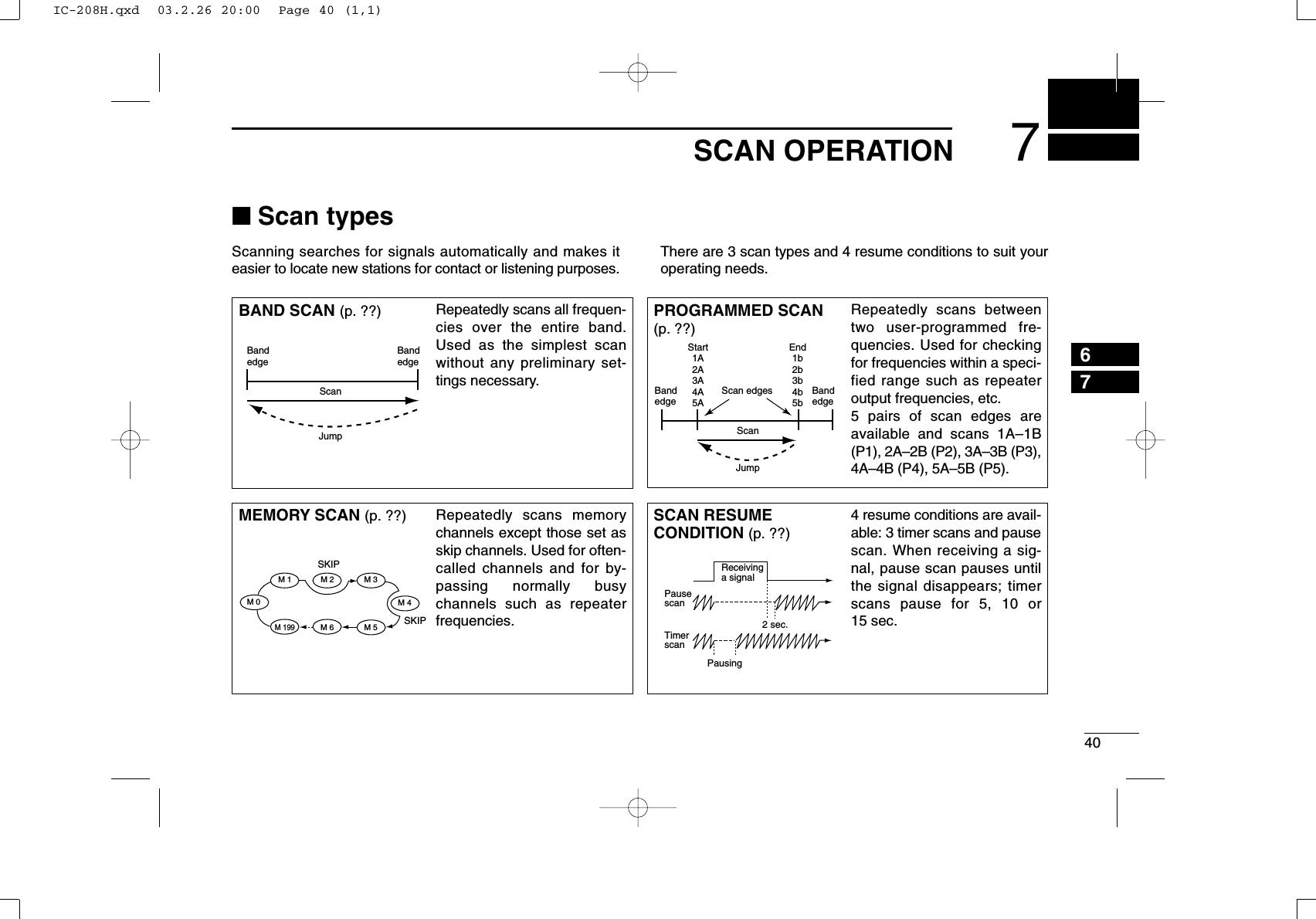
![417SCAN OPERATIONNew2001■Scan start/stopDPreparationScan resume condition (p. ??); program the scan edges(pgs. ??, ??); program 2 or more memory channels (pgs. ??,??); set skip settings, if desired (p. ??).DOperationqSelect VFO mode for full/programmed scan with[V/MHz•SCAN]; or memory mode for memory scan with[M/CALL•PRIO].•Select the desired bank for bank scan.wSet the squelch to the point where noise is just muted.ePush [V/MHz•SCAN] for 1 sec. to start the scan.•To change the scanning direction, rotate [DIAL].•The memory channel readout blinks the scan type as follows:rPush [SET•LOCK] to switch full and programmed scan(P1, P2, P3, P4 and P5), if VFO is selected in step q.tTo stop the scan, push [V/MHz•SCAN].zPush [VFO/LOCK] to select VFO mode forfull/programmed scan; push [MR/CALL] to selectmemory mode for memory scan.•Push [FUNC] then [MONI1(BANK)] to select a bankfor bank scan.xPush [SQLYD(MUTE)] or [SQLZ#(16KEY-L)] toset the squelch to the point where noise is justmuted.cPush [SCAN2(T-SCAN)] to start the scan.•Push [Y] or [Z] for 1 sec. also starts the scan.vPush [SETB(D-OFF)] to switch full and pro-grammed scan (P1, P2, P3, P4 and P5), if VFOis selected in step z.bTo stop the scan push [SCAN2(T-SCAN)] or[CLRA(MW)].SCAN2SETB• During full scan • During programmed scan • During memory scan • During bank scanIndicates scan edge channels.¥ P1 stands for 1A/1B¥ P1 to P5 are available when they are programmed, and switches with [SET/LOCK].Indicates bank initial.Push [SET/LOCK] to select ALL (full) or programmed scan (P1, P2, P3, P4 and P5) in sequence.IC-208H.qxd 03.2.26 20:00 Page 41 (1,1)](https://usermanual.wiki/ICOM-orporated/263300/User-Guide-319595-Page-56.png)
![427SCAN OPERATIONNew20017■Scan edges programmingScan edges can be programmed in the same manner asmemory channels. Scan edges are programmed into scanedges, 1A/1B to 5A/5B, in memory channels.qSet the edge frequency of the desired frequency range inVFO mode:➥Set the frequency using [DIAL].➥Set other data (e.g. repeater settings, etc.) if desired.wPush [S.MW•MW].•“!” indicator and channel number blink.eRotate [DIAL] to select one of scan edge channel, 1A, 2A,3A, 4A or 5A.rPush [S.MW•MW] for 1 sec. to program.•3 beeps sound and VFO is automatically selected.•Scan edge 1B, 2B, 3B, 4B or 5B is automatically selected whencontinuing to push [S.MW•MW] after programming.tTo program a frequency for the other pair of scan edges,1B, 2B, 3B, 4B or 5B, repeat steps qand r.•If the same frequency is programmed into a pair of scan edges,programmed scan will not function.[EXAMPLE]: Programming 145.300 MHz into scan edges 1A.Push [S.MW/MW] for 1 sec.Rotate for setting frequency, etc. RotatePush for 1 sec. and continue to push ➠BeepBeepBeep“Beep“““““IC-208H.qxd 03.2.26 20:00 Page 42 (1,1)](https://usermanual.wiki/ICOM-orporated/263300/User-Guide-319595-Page-57.png)
![437SCAN OPERATIONNew2001DProgramming scan edges via microphonezSet the desired frequency in VFO mode.➥Push [VFO/LOCK] to select VFO mode.➥Set the frequency via the keypad or [Y]/[Z].xPush [FUNC] then [CLRA(MW)] momentarily.cPush [Y] or [Z] to select scan edge channels,1A, 2A, 3A, 4A or 5A.vPush [FUNC], then push [CLRA(MW)] for 1 sec.to program.•3 beeps sound and VFO is automatically selected.•Memory channel number advances to the next scanedge channel, 1B, 2B, 3B, 4B or 5B when continuingto push [CLRA(MW)] after programming.bTo program a frequency for the other scan edge channels,repeat steps zto v.MW[EXAMPLE]: Programming 145.800 MHz into scan edge 1B.Push Push Push then momentarilyPush Push then for 1 sec. and continue to push ➠Beep“BeepBeepBeep“““““IC-208H.qxd 03.2.26 20:00 Page 43 (1,1)](https://usermanual.wiki/ICOM-orporated/263300/User-Guide-319595-Page-58.png)
![447SCAN OPERATIONNew20017■Skip channel setting[The memory skip function speeds up scanning by checkingonly those memory channels not set as skip channels. Setskip channels as follows.qSelect a memory channel:➥Push [M/CALL•PRIO] to select memory mode.➥Rotate [DIAL] to select the desired channel to be a skipchannel.wPush [SET•LOCK] to enter set mode.ePush [SET•LOCK] or [S.MW•MW] several times until“CHS” appears as shown above.rRotate [DIAL] to turn the skip function ON or OFF for theselected channel.•“~” appears : The channel is skipped during scan. (CHS-ON)•“P~” appears : The channel is skipped during scan and theprogrammed frequency is skipped during VFO scan, such asprogrammed scan. (CHS-ON)•“~” disappears : The channel is scanned during scan.(CHS-OF)tPush [MONI•DTMF] to exit set mode.zSelect a memory channel.➥Select memory mode by pushing [MR/CALL].➥Push [Y] or [Z] to select the desired channelto be a skip channel.•Direct memory channel selection is also available.xPush [SETB(D-OFF)] to enter set mode.cPush [SETB(D-OFF)] or [ENTC(T-OFF)] severaltimes until “CHS” appears as shown at left.vPush [Y] or [Z] to set or cancel the skip setting.•See item rat left for skip indicator details.bPush [CLRA(MW)] to exit set mode.SETBThe display shows that mem-ory channel 1 is set as a skip channel.IC-208H.qxd 03.2.26 20:00 Page 44 (1,1)](https://usermanual.wiki/ICOM-orporated/263300/User-Guide-319595-Page-59.png)
![457SCAN OPERATIONNew2001■Scan resume condition[The scan resume condition can be selected as timer or pausescan. The selected resume condition is also used for prioritywatch. (p. ??)qPush [SET•LOCK] to enter set mode.wPush [SET•LOCK] or [S.MW•MW] several times until“SCT” or “SCP” appears as shown above.•When “d” is displayed in place of the 100 MHz digit, cancel theDTMF memory encoder in advance. (p. ??)eRotate [DIAL] to set the desired timer:•“SCT-15”: Scan pauses 15 sec. while receiving a signal.•“SCT-10”: Scan pauses 10 sec. while receiving a signal.•“SCT-5”: Scan pauses 5 sec. while receiving a signal.•“SCP-2”: Scan pauses until the signal disappears and thenresumes 2 sec. later.rPush [MONI•DTMF] to exit set mode.zPush [BAND] to select the desired band.xPush [SETB(D-OFF)] to enter set mode.cPush [SETB(D-OFF)] or [ENTC(T-OFF)] severaltimes until “SCT” or “SCP” appears as shown atleft.vPush [Y] or [Z] to select the scan resume condi-tion.•See item rat left for scan resume condition details.bPush [CLRA(MW)] to exit set mode.SETBThe display shows that the scan will resume 15 sec. after it stops.IC-208H.qxd 03.2.26 20:00 Page 45 (1,1)](https://usermanual.wiki/ICOM-orporated/263300/User-Guide-319595-Page-60.png)
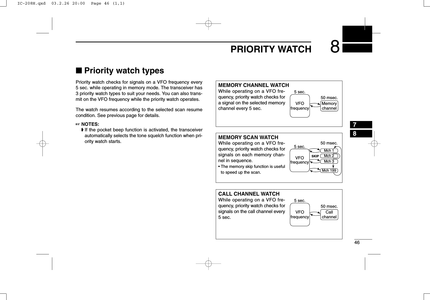
![478PRIORITY WATCHNew2001■Priority watch operationqSelect VFO mode; then, set an operating frequency.wSet the watching channel(s).For memory channel watch:Select the desired memory channel.For memory scan watch:Select memory mode; then, push [V/MHz•SCAN] for 1 sec.to start memory scan.For call channel watch:Select the desired call channel by pushing [M/CALL•PRIO]once or twice, then rotate [DIAL].ePush [M/CALL•PRIO] for 1 sec. to start the watch.•The transceiver checks the memory or call channel every 5 sec.•The watch resumes according to the selected scan resume con-dition. (p. ??)•While the watch is pausing, pushing [M/CALL•PRIO] resumesthe watch manually.rPush [M/CALL•PRIO] for 1 sec. to stop the watch.zSelect VFO mode; then, set the desired fre-quency.xSet the watching channel(s).For memory channel watch:Push [MR/CALL] then [Y] or [Z] to select the de-sired memory channel.For memory scan watch:Push [MR/CALL], then push [SCAN2] to start thememory scan.For call channel watch:Push [MR/CALL] for 1 sec. then push [Y] or [Z]to select the call channel.cPush [PRIO3(PTT-M)] to start the watch.•The transceiver checks the memory or call channelevery 5 sec.•The watch resumes according to the selected scan re-sume condition. (p. ??)•To resume the watch manually when paused, push[PRIO3(PTT-M)] or [CLRA(MW)].vTo stop the watch, push [CLRA(MW)] once (ortwice while watch is paused).PRIO3IC-208H.qxd 03.2.26 20:00 Page 47 (1,1)](https://usermanual.wiki/ICOM-orporated/263300/User-Guide-319595-Page-62.png)
![489DTMF MEMORY ENCODER89■Programming a DTMF codeDTMF tones are used for autopatching, controlling otherequipment, etc. The transceiver has 16 DTMF memory chan-nels (D0–DF) for storage of often-used DTMF codes of up to24 digits.qPush [MONI•DTMF] for 1 sec. to turn the DTMF encoderON.•“d” appears in place of 100 MHz digit.wPush [SET•LOCK] to enter the DTMF memory program-ming condition.•The DTMF memory channel indication blinks.eRotate [DIAL] to select the desired DTMF memory chan-nel.rPush [SET•LOCK].•The first digit blinks.tRotate [DIAL] to select the desired code.yPush [SET•LOCK] to select the next digit.•Pushing [S.MW•MW] move the cursor backward.uRepeat the steps tand yto set the desired DTMF tonesequence.•The S/RF indicator shows the digit group. The indication in-creases every 6 digits.iPush [MONI•DTMF]to exit DTMF memory programmingcondition.•Return to the previous indication as in step q.[EXAMPLE]: Programming “5428AB453” into DTMF memory channel “d4.”PushPush then rotate Repeat the previous step until the desired code is entered. PushRotatePush for 1 sec.IC-208H.qxd 03.2.26 20:00 Page 48 (1,1)](https://usermanual.wiki/ICOM-orporated/263300/User-Guide-319595-Page-63.png)
![499DTMF MEMORY ENCODERNew2001DProgramming a DTMF code— via microphonezPush [FUNC] then [LOW6(DTMF)] to turn theDTMF encoder ON.•“d” appears in place of 100 MHz digit.xPush [SETB(D-OFF)] to enter the DTMF memoryprogramming condition.cPush [Y] or [Z] to select the desired DTMFmemory channel.vPush the desired digit keys.•When the first digit is input, previous memory contentsare cleared automatically.•“E” stands for “MM” and “F” stands for “# .”•Push [Y]/[Z] and repeat this step if you make a mistake.•The S/RF indicator shows the digit group. The indicationincreases every 6 digits.bPush [VFO/LOCK] to exit the programming condition.•The [CLRA(MW)] key cannot be used to exit. If pushed, code “A”is input. Reprogram in such a case.DTMF[EXAMPLE]: Programming “5428AB453” into DTMF memory channel “D4.”PushPush PushPushPush then .IC-208H.qxd 03.2.26 20:00 Page 49 (1,1)](https://usermanual.wiki/ICOM-orporated/263300/User-Guide-319595-Page-64.png)
![509DTMF MEMORY ENCODERNew20019■Transmitting a DTMF codeDAutomatic transmission (DTMF memory)qPush [MONI•DTMF] for 1 sec. to turn the DTMF memoryencoder ON.• “d” appears in place of 100 MHz digit.wPush [SET•LOCK] to enter DTMF memory programmingcondition.eRotate [DIAL] to select the desired DTMF memory chan-nel.rPush [PTT] to transmit the selected DTMF memory content.tPush [MONI•DTMF] for 1 sec. to cancel the DTMF en-coder.•When the DTMF encoder is turned ON continuously, each pushof the PTT transmits the previously selected DTMF code.zPush [FUNC] then [LOW6(DTMF)] to turn theDTMF memory encoder ON.•“d” appears in place of 100 MHz digit.xPush [SETB(D-OFF)] to enter the DTMF memoryprogramming condition.cPush [Y] or [Z] to select the desired channel.vPush [PTT] to transmit the selected memory.•Exit the programming condition automatically.•Each push of [PTT] transmits the DTMF code.bPush [FUNC] then [SETB(D-OFF)] to cancel theDTMF memory encoder.•When the DTMF encoder is turned ON continuously,each push of the PTT transmits the previously se-lected DTMF code.DTransmitting a DTMF memory directlyzPush [FUNC] then [LOW6(DTMF)] to turn theDTMF memory encoder ON.•“d” appears in place of 100 MHz digit.xPush [DTMF-S] to turn the DTMF memory di-rect selection ON.•The function indicator (microphone) lights green.cPush the desired DTMF channel.•“0” to “9” and “A” to “D” are available for DTMFmemory channels.•The selected DTMF code is automatically transmit-ted without pushing PTT.NOTE: When no DTMF code programmedchannel number is pushed, it transmits the rela-tive DTMF code as the manual transmission de-scribed in the next page.vPush [DTMF-S] again to deactivate the DTMFmemory direct selection.bPush [FUNC] then [SETB(D-OFF)] to cancelthe DTMF memory encoder.DTMF-SDTMFIC-208H.qxd 03.2.26 20:00 Page 50 (1,1)](https://usermanual.wiki/ICOM-orporated/263300/User-Guide-319595-Page-65.png)
![519DTMF MEMORY ENCODERNew2001DManual transmissionzDeactivate the DTMF memory encoder bypushing [FUNC] then [SETB(D-OFF)].xPush [DTMF-S] to turn the DTMF direct selec-tion ON.•The function indicator (microphone) lights green.cPush one of “0” to “9” and “A” to “F” keys mo-mentarily, then push the desired DTMF keys,0–9 and A to F.•A: [CLRA(MW)] B: [SETB(D-OFF)], C: [ENTC(T-OFF)] D: [SQLYD(MUTE)], E: [MM(TONE-1)] F: [SQLZ#(16KEY-L)]•Automatically transmits without pushing PTT.•The first code, one of “A” to “F,” is not transmitted.DTMF code transmission starts from the 2nd code.vPush [DTMF-S] again to deactivate the DTMFdirect selection.■DTMF speedThe rate at which DTMF memories send individual DTMFcharacters can be set to accommodate operating needs.qPush [PWR] for 1 sec. to turn power OFF.wWhile pushing [SET•LOCK], push [PWR] for 1 sec. to turnpower ON and enter initial set mode.ePush [SET•LOCK] or [S.MW•MW] several times until“DTD” appears as shown above.rRotate [DIAL] to select the desired speed as shown in thetable below.tPush [PWR] to exit initial set mode.cps=characters/secThe display shows the fastest DTMF speed is selected.USINGINITIAL SET MODEDTMF-SIC-208H.qxd 03.2.26 20:00 Page 51 (1,1)](https://usermanual.wiki/ICOM-orporated/263300/User-Guide-319595-Page-66.png)
![5210POCKET BEEP AND TONE SQUELCH910■Pocket beep operationThis function uses subaudible tones for calling and can beused as a “common pager” to inform you that someone hascalled while you were away from the transceiver.DWaiting for a call from a specific stationqSet the operating frequency.wPush [SET•LOCK] to enter set mode.ePush [SET•LOCK] or [S.MW•MW] several times until “CT”for tone squelch or “DT” for DTCS squelch appears.rRotate [DIAL] to select the desired tone squelch frequency.tWhen operating the pocket beep function with DTCSsquelch, push [SET•LOCK] once then rotate [DIAL] to se-lect the DTCS polarity.yPush [TONE•T-SCAN] to exit set mode.uPush [TONE•T-SCAN] several times until “T SQLS” or“SDTCS” are displayed to turn ON the pocket beep withtone squelch or DTCS squelch, respectively.iWhen a signal with the matched tone is received, thetransceiver emits beep tones and blinks “S”.•Beep tones sound for 30 sec. and “S” blinks. To stop thebeeps and blinking manually, push any key. When the beeptones are not stopped manually, “S” continues blinking until[PTT] is pushed (see step o).oPush [PTT] to answer.•“S” disappears and cancels the pocket beep function auto-matically.!0 Push [TONE•T-SCAN] several times until “T SQL” or“DTCS” disappears to cancel the tone squelch or DTCSsquelch function.Push [TONE•T-SCAN] several times to select the pocket beepfunction with tone squelch or DTCS squelch.Appears when the pocket beepwith tone squelch is activated.Appears when the pocket beepwith DTCS squelch is activated.DTCS polarity settingTone squelch frequency setting DTCS code settingIC-208H.qxd 03.2.26 20:00 Page 52 (1,1)](https://usermanual.wiki/ICOM-orporated/263300/User-Guide-319595-Page-67.png)
![5310 POCKET BEEP AND TONE SQUELCHNew2001zSet the operating frequency.xProgram the CTCSS tone frequency or DTCScode in set mode.➥Push [SETB(D-OFF)] to enter set mode.➥Push [SETB(D-OFF)] or [ENTC(T-OFF)]several times until “CT” for tone squelch or“DT” for DTCS squelch appears.•“T SQL” blinks when tone squelch (“CT”), or“DTCS” blinks when DTCS squelch (“DT”) isselected.➥Push [Y]/[Z] to select the desired tone fre-quency or DTCS code.➥Push [SETB(D-OFF)] to select “DTP” thenpush [Y]/[Z] to select the DTCS polarity.➥Push [CLRA(MW)] to exit set mode.cPush [FUNC] then push [DUP+ 8(TSQLS)]or [MID5(DTCSS)] to turn ON the pocketbeep with tone squelch or DTCS squelch, re-spectively.vWhen a signal with the matched tone is re-ceived, the transceiver emits beep tones for30 sec. and blinks “S.”bPush [PTT] to answer or push [CLRA(MW)] tostop the beeps and blinking.•“S” disappears and cancels the pocket beepfunction automatically.nTo cancel the tone squelch or DTCS squelchfunction, push [FUNC] then [ENTC(T-OFF)]. •“T SQL” or “DTCS” disappears DAvailable tone frequency listNOTE: The transceiver has 50 tone frequencies and con-sequently their spacing is narrow compared to units having38 tones. Therefore, some tone frequencies may receiveinterference from adjacent tone frequencies.To prevent interference from adjacent tone frequencies,using the frequencies as in the following table, is recom-mended.DCalling a waiting station using pocket beepA subaudible tone matched with the station’s CTCSS tone fre-quency or 3-digit DTCS code with polarity is necessary. Usethe tone squelch on the next page or a subaudible tone en-coder (pgs. ??, ??).67.069.371.974.488.591.594.897.4114.8118.8123.0127.3151.4156.7162.2167.9203.5210.7218.1225.777.079.782.585.4100.0103.5107.2110.9131.8136.5141.3146.2173.8179.9186.2192.8233.6241.8250.3• Recommended tone frequencies67.069.371.974.477.079.782.585.488.591.594.897.4100.0103.5107.2110.9114.8118.8123.0127.3131.8136.5141.3146.2151.4156.7159.8162.2165.5167.9171.3173.8177.3179.9183.5186.2189.9192.8196.6199.5203.5206.5210.7218.1225.7229.1233.6241.8250.3254.1TSQLSDTCSSIC-208H.qxd 03.2.26 20:00 Page 53 (1,1)](https://usermanual.wiki/ICOM-orporated/263300/User-Guide-319595-Page-68.png)
![5410POCKET BEEP AND TONE SQUELCHNew200110■Tone/DTCS squelch operationThe tone or DTCS squelch opens only when receiving a sig-nal with the same pre-programmed subaudible tone or DTCScode, respectively.qSet the operating frequency.wProgram the CTCSS tone frequency or DTCS code in setmode.•See p. ?? for programming details.ePush [TONE•T-SCAN] several times until “T SQL” or“DTCS” appears in the function display.rWhen a signal with the matched tone is received, thesquelch opens and the signal can be heard.•When the received signal includes an unmatched tone, thesquelch does not open. However, the S/RF indicator shows thereceived signal strength.•To open the squelch manually, push [MONI•DTMF].tOperate the transceiver in the normal way (push [PTT] totransmit; release [PTT] to receive).yTo cancel the tone squelch, push [TONE•T-SCAN] severaltimes until “T SQL” or “DTCS” disappears.zSet the operating frequency.xProgram the CTCSS tone frequency or DTCScode in set mode.•See p. ?? for programming details.cPush [FUNC] then [SIMP9(TSQL)] or [HIGH4(DTCS)]to turn the tone squelch or DTCS squelch ON.vWhen a signal with the matched tone is re-ceived, the squelch opens and the signal can beheard.•When the received signal includes an unmatchedtone, the squelch does not open. However, the S/RFindicator shows the received signal strength.•To open the squelch manually, push [MONI1(BANK)].bOperate the transceiver in the normal way (push[PTT] to transmit; release [PTT] to receive.nTo cancel the tone squelch, push [FUNC] then[ENTC(T-OFF)].•“T SQL” or “DTCS” disappears TSQLDTCSIC-208H.qxd 03.2.26 20:00 Page 54 (1,1)](https://usermanual.wiki/ICOM-orporated/263300/User-Guide-319595-Page-69.png)
![5510 POCKET BEEP AND TONE SQUELCHNew2001■Tone scanBy monitoring a signal that is being operated with pocketbeep, tone or DTCS squelch function, you can determine thetone frequency or DTCS code necessary to open a squelch.qSet the desired operating frequency or memory channel tobe checked for a tone frequency or code.wPush [TONE•T-SCAN] several times to select the tonetype, tone squelch or DTCS, to be scanned.•Either “T SQL” or “DTCS” appears ePush [TONE•T-SCAN] for 1 sec. to start the tone scan.•To change the scanning direction, rotate [DIAL].rWhen the CTCSS tone frequency or 3-digit DTCS code ismatched, the squelch opens and the tone frequency istemporarily programmed into the selected condition suchas memory or call channel.•The tone scan pauses when a CTCSS tone frequency or 3-digitDTCS code is detected.•The decoded CTCSS tone frequency or 3-digit DTCS code isused for the tone encoder or tone encoder/decoder dependingon the selected tone condition or type in step w. -“T SQL” : CTCSS tone encoder/decoder-“DTCS” : DTCS tone encoder/decodertPush [TONE•T-SCAN] to stop the scan.zSet the frequency or memory channel to bechecked for a tone frequency.xSelects the tone type to be scanned.•Push [FUNC] then push; [SIMP9(TSQL)] for tonesquelch; [HIGH4(DTCS)] for DTCS squelch.cPush [FUNC] then [SCAN2(T-SCAN)] to startthe tone scan.vWhen the tone frequency is matched, thesquelch opens and the tone frequency is pro-grammed into the selected mode such asmemory or call channel.bPush [CLRA(MW)] to stop the scan.☞NOTE: The decoded tone frequency is programmed tem-porarily when a memory or call channel is selected. How-ever, this will be cleared when the memory/call channel isre-selected.T-SCANDuring CTCSS frequency scan During DTCS code scanPush [TONE•T-SCAN] for 1 sec. to start tone scan.IC-208H.qxd 03.2.26 20:00 Page 55 (1,1)](https://usermanual.wiki/ICOM-orporated/263300/User-Guide-319595-Page-70.png)
![5611OTHER FUNCTIONS1011■Set mode•Set mode operationqPush [SET•LOCK] to enter the set mode.wPush [SET•LOCK] or [S.MW•MW] to select the desireditem.eRotate [DIAL] to select the condition or value.rPush[MONI•DTMF] to exit set mode.•Set mode itemszPush [SETB(D-OFF)] to enter set mode.xPush [SETB(D-OFF)] or [ENTC(T-OFF)] to selectthe desired item.cPush [Y] or [Z] to select the condition or value.vPush [CLRA(MW)] to exit set mode.SETB*Available for USA version only.†Appears when accessing set mode from VFO mode only.‡Appears when accessing set mode from memory mode only.: Push (front panel); or (microphone): Push (front panel); or (microphone)• Weather alert*• Display dimmer • Display color • Repeater tonefrequency• Tone squelchfrequency • DTCS code • DTCS polarity• Offset frequency• Tuning step• Scan resume timer• Channel skip setting‡• Bank link function‡• Mic lock function• Program skip†• Bank setting‡• Memory name‡IC-208H.qxd 03.2.26 20:00 Page 56 (1,1)](https://usermanual.wiki/ICOM-orporated/263300/User-Guide-319595-Page-71.png)
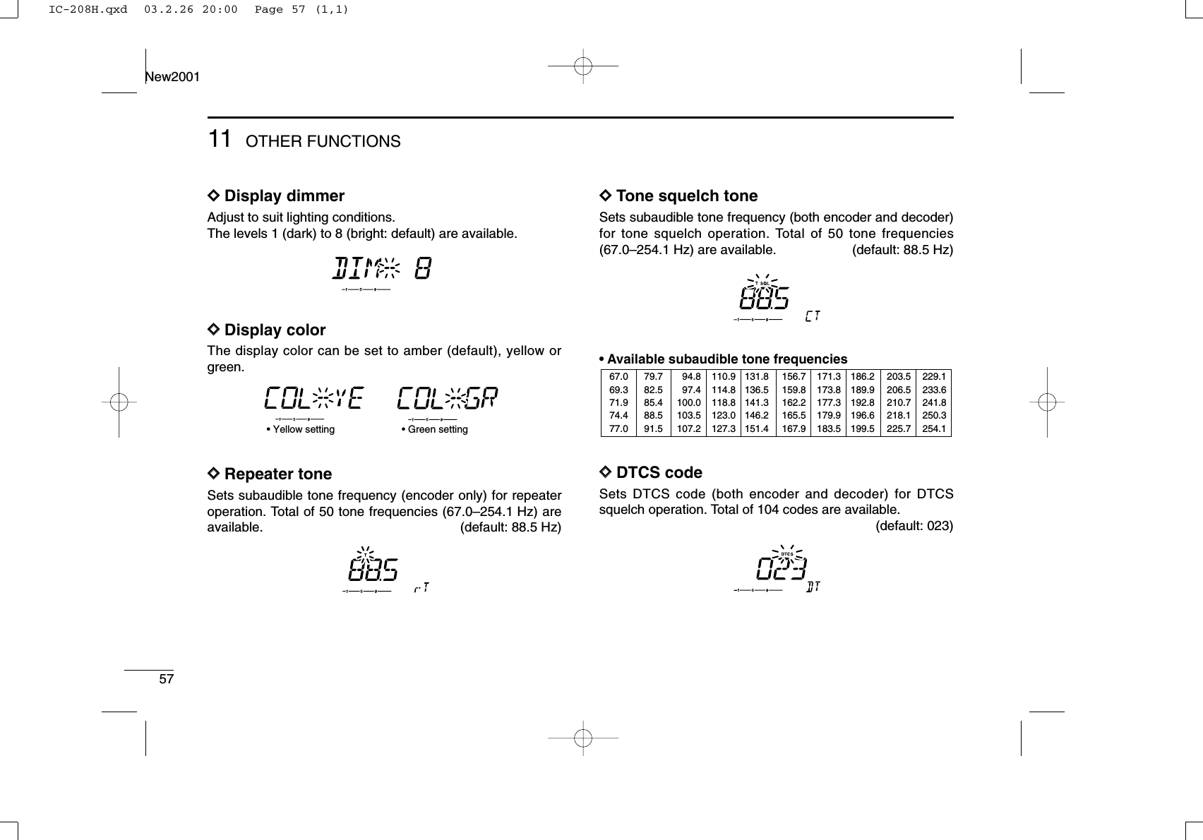
![5811OTHER FUNCTIONSNew200111DDDTCS polaritySets DTCS polarities for transmission and reception from“NN,” “NR,” “RN” and “RR.”(default: NN)DDOffset frequencySets the duplex offset frequency within 0 to 20 MHz range.During duplex (repeater) operation, transmit frequency (or re-ceive when reverse function is set to ON) shifts the set fre-quency. (default value may differ depending on operating frequencyband and versions)DDTuning stepSelects tuning step from 5, 10, 12.5, 15, 20, 25, 30. 50, 100and 200 kHz for [DIAL] or [Y]/[Z] operation. (default value maydiffer depending on operating frequency band and versions) DDScan resume timerSelects scan resume timer from SCT-15 (default), SCT-10,SCT-5 and SCP-2. •SCT-15/10/5 : Scan pauses for 15/10/5 sec., then re-sumes.•SCP-2 : Pause on a signal until signal disap-pears, then resumes 2 sec. after the sig-nal disappears.• Transmit : normal Receive : normal (default)• Transmit : normal Receive : reverseIC-208H.qxd 03.2.26 20:00 Page 58 (1,1)](https://usermanual.wiki/ICOM-orporated/263300/User-Guide-319595-Page-73.png)
![6011OTHER FUNCTIONSNew200111DDWeather alert functionTurns weather alert function ON and OFF.DDMic lock functionSets the supplied HM-133’s (optional for some versions) keylock function from ON and OFF (default).DDMemory bank link functionSets the memory bank link function ON and OFF (default).The link function provides continuous banks scan, that scansall contents in the selected banks during bank scan.This item appears when set mode is accessed from memorymode only.•Bank link settingqRotate [DIAL] to select the memory bank link function ON.wPush [SET•LOCK] or [S.MW•MW] to select the desiredbank to be linked.•BLA: Bank A, BLB: Bank B, BLC: Bank C, BLD: Bank D, BLE: Bank E, BLF: Bank F, BLG: Bank G, BLH: Bank H, BLI: Bank I, BLC: Bank J, BLC: Bank J eRotate [DIAL] to select “ON” to linking the bank.rRepeat steps wand eto set the link condition.U.S.A. version onlyIC-208H.qxd 03.2.26 20:00 Page 60 (1,1)](https://usermanual.wiki/ICOM-orporated/263300/User-Guide-319595-Page-75.png)
![6111 OTHER FUNCTIONSNew2001■Initial set modeThe initial set mode is accessed at power ON and al-lows you to set seldom-changed settings. In this way,you can “customize” transceiver operations to suit yourpreference and operating style.•Initial set mode itemsDDEntering initial set modeqWhile pushing [SET•LOCK] push [PWR] for 1 sec. to enterinitial set mode.wPush [SET•LOCK] or [S.MW•MW] to select the desireditem.eRotate [DIAL] to select the condition or value.rPush [PWR]momentarily to exit initial set mode.ATPOWER ON• Active band• Key-touch beep • Time-out timer • Auto repeater*• Squelch attenuator • Microphone sensitivity• Auto power off• DTMF speed• Squelch delay• Data speed• Cooling fan*Available in the USA version only.• Narrow TX: Push (front panel); or (microphone): Push (front panel); or (microphone)IC-208H.qxd 03.2.26 20:00 Page 61 (1,1)](https://usermanual.wiki/ICOM-orporated/263300/User-Guide-319595-Page-76.png)
![6311 OTHER FUNCTIONSNew2001DDCooling fan controlSelects the cooling fan control condition from Auto and ON.•Auto (AT) : The fan rotates during transmit and for 2 min.after transmission.•ON (ON) : The fan continuously rotates. DDData transmission speedSelects the data transmission speed for packet operationfrom 1200 bps and 9600 bps.DDSquelch delaySelects squelch delay from short and long to prevent re-peated opening and closing of the squelch during receptionof the same signal.•S : Short squelch delay.•L : Long squelch delayDDMicrophone sensitivitySelects the microphone sensitivity from high (H) and low (L)to suits your preference.DDSquelch attenuatorTurns the squelch attenuator function ON and OFF.•ON : The squelch attenuator activates when [SQL]control is set between 12 o’clock and fullyclockwise position.•OF : The squelch attenuator does not function.IC-208H.qxd 03.2.26 20:00 Page 63 (1,1)](https://usermanual.wiki/ICOM-orporated/263300/User-Guide-319595-Page-78.png)
![6411OTHER FUNCTIONSNew200111DDActive bandSelects the frequency selecting condition via [DIAL] or [Y]/[Z]on the microphone from all (AL) and single (SI).•All (AL) : The operating frequency can be selectedcontinuously.•Single (SI) : The operating frequency can be selectedwithin the current band. Pushing [BAND] for1 sec. then tuning dial rotation is necessaryfor frequency band selection.DDNarrow TX functionSelect the narrow TX function ON and OFF.•ON : Enables the FM-narrow mode transmission. Thedeviation (modulation level) becomes harf fromthe regular FM transmission can be performed.•OFF : Inhibits the FM-narrow mode transmission. Theregular FM deviation transmission is performed(“NAR” indication disappears) even when FM-narrow is selected.DDDTMF speedThe rate at which DTMF memories send individual DTMFcharacters can be set to accommodate operating needs.•1 : 100 msec. interval; 5.0 cps speed•2 : 200 msec. interval; 2.5 cps speed •3 : 300 msec. interval; 1.6 cps speed •5 : 500 msec. interval; 1.0 cps speed IC-208H.qxd 03.2.26 20:00 Page 64 (1,1)](https://usermanual.wiki/ICOM-orporated/263300/User-Guide-319595-Page-79.png)
![6511 OTHER FUNCTIONSNew2001■AM/FM narrow modeThe IC-208 has AM mode reception and FM narrow mode isavailable. Typically, AM (narrow) mode is used for the airband (118–135.995 MHz).qSelect the desired frequency band in VFO mode, or the de-sired memory channel.wPush [BAND] for 1 sec. to select AM/FM narrow mode asdesired.•“NAR” (FM narrow), “AM” and “NAR AM” appears in sequence.• No indicationstands for FM mode.zPush [BAND] or [MR/CALL] to select the desiredfrequency band or memory channel.xPush [BAND] for 1 sec. to select AM/FM narrowmode as desired.•“NAR”, “AM” and “NAR AM” appears in sequence.• No indicationstands for FM mode.SETB• When FM narrow mode is selected• When AM mode is selected• When AM narrow mode is selectedIC-208H.qxd 03.2.26 20:00 Page 65 (1,1)](https://usermanual.wiki/ICOM-orporated/263300/User-Guide-319595-Page-80.png)
![6611OTHER FUNCTIONSNew200111■Weather channel operation(USA version only)DDWeather channel selectionqPush [M/CALL•PRIO] several times to select weatherchannel group. wRotate [DIAL] to select the desired weather channel. ePush [M/CALL•PRIO] to select memory mode, or push[V/MHz•SCAN] to select VFO mode.DDWeather alert functionNOAA broadcast stations transmit weather alert tones beforeimportant weather announcements. When the weather alertfunction is turned ON, the selected weather channel is moni-tored each 5 sec. for the announcement. When the alert sig-nal is detected, the “AL.t” and the WX channel are displayedalternately and sounds a beep tone until the transceiver is op-erated. The previously selected (used) weather channel ischecked periodically during standby or while scanning.qSelect the desired weather channel.wTurn the weather alert function ON in set mode.➥Push [SET•LOCK] to enter set mode.➥Push [SET•LOCK] or [S.MW•MW] to select the weatheralert item, then rotate [DIAL] to set ON.➥Push [MONI•DTMF] to exit set mode.eSets the desired stand-by condition.•Selects VFO, memory or call channel.•Scan or priority watch operation can also be selected.rWhen the alert is detected, a beep sounds and the follow-ing indication will be displayed.tTurn the weather alert function OFF in set mode.☞NOTE: While receiving a signal (on a frequency other thanthe weather alert ON frequency), the receiving signal oraudio will be interrupted momentarily every 5 sec. (approx.)in case the alert function is turned ON. This symptom iscaused by the WX alert function. To cancel these symp-toms, set the weather alert item OFF in set mode.Shows above indications alternately.Weather channel group indicaiton[M/CALL•PRIO]IC-208H.qxd 03.2.26 20:00 Page 66 (1,1)](https://usermanual.wiki/ICOM-orporated/263300/User-Guide-319595-Page-81.png)
![6711 OTHER FUNCTIONSNew2001■Microphone keysThe supplied HM-133’s (optional for some versions) [F-1] and[F-2] keys memorize the transceiver conditions. The [UP]/[DN] keys of the standard or an optional microphone(other than the HM-133) can be assigned functions like thefunction keys on the transceiver’s front panel.DD[UP]/[DN] keys on a microphones(other than HM-133)The following functions are assigned to [UP]/[DN] keys on theother microphones (HM-118N/TAN, etc.) when first applyingpower.•Default setting[UP] : channel up; push and hold to start scan, push againto stop scan.[DN] : channel down; push and hold to start scan, pushagain to stop scan.➥Assigning a functionqTurn the power OFF.wWhile pushing the desired switch on the transceiver andone of either [UP]/[DN] keys on the microphone, turn thepower ON.•The function is programmed into the key.➥Clearing an assignmentqTurn the power OFF.wWhile pushing the desired [UP] or [DN] key on the micro-phone, turn the power ON.DD[F-1]/[F-2] keys on HM-133The following conditions can be memorized into [F-1] and [F-2] keys, independently.•Operating frequency•Repeater setting (offset direction and frequency, tone ON/OFFand frequency)•Tone/DTCS squelch (ON/OFF, frequency/code and polarity)•Transmit output power selection•Tuning step•Operating mode selection (FM/AM)•Set mode settings*•Initial set mode settings**Only when storing both bands conditions➥Programming the band conditionPush [FUNC] then push [F-1]/[F-2] for 1 sec.•3 beeps sound.➥Recalling the band conditionPush [FUNC] then [F-1]/[F-2] momentarily.[F-1]/[F-2]ATPOWER ONIC-208H.qxd 03.2.26 20:00 Page 67 (1,1)](https://usermanual.wiki/ICOM-orporated/263300/User-Guide-319595-Page-82.png)
![6811OTHER FUNCTIONSNew200111■Partial resetIf you want to initialize the operating conditions (VFO fre-quency, VFO settings, set mode contents) without clearingthe memory contents.➥While pushing [V/MHz•SCAN] and [SET•LOCK], push[PWR] for 1 sec. to partially reset.■ALL resetThe function display may occasionally display erroneous in-formation (e.g. when first applying power). This may becaused externally by static electricity or by other factors.If this problem occurs, turn power OFF. After waiting a fewseconds, turn power ON again. If the problem persists, per-form the following procedure.•Partial resetting is also available. See left for details.IMPORTANT!:Resetting the transceiver CLEARS all memory informationand initializes all values in the transceiver.➥While pushing [S.MW•MW] and [SET•LOCK], push [PWR]for 1 sec. to reset the CPU.[S.MW•MW][SET•LOCK] [PWR]ATPOWER ON[S.MW•MW][PWR][V/MHz•SCAN]ATPOWER ONIC-208H.qxd 03.2.26 20:01 Page 68 (1,1)](https://usermanual.wiki/ICOM-orporated/263300/User-Guide-319595-Page-83.png)
![6911 OTHER FUNCTIONSNew2001■Data cloningCloning allows you to quickly and easily transfer the pro-grammed contents from one transceiver to another; or, datafrom a personal computer to a transceiver using the optionalCS-208 CLONING SOFTWARE.DCloning between transceiversqConnect the OPC-474 cloning cable to [SP] jack of themaster and sub-transceivers.•The master transceiver is used to send data to the sub-trans-ceiver.wWhile pushing [M/CALL•PRIO], turn power ON to entercloning mode (master transceiver only— power on only forsub-transceiver).•“CLONE” appears and the transceivers enter the clone standbycondition.ePush [SET•LOCK] on the master transceiver.•“CL OUT” appears in the master transceiver’s display and theS/RF indicators show that data is being transferred to the sub-transceiver.•“CL IN” appears automatically in the sub-transceiver’s displayand the S/RF indicators show that data is being received fromthe master transceiver.rWhen cloning is finished, turn power OFF, then ON to exitcloning mode.Pushing [SET•LOCK] start cloning.While pushing [M/CALL•PRIO], turn power ON.[PWR][M/CALL•PRIO]To [SP] To [SP]ATPOWER ONIC-208H.qxd 03.2.26 20:01 Page 69 (1,1)](https://usermanual.wiki/ICOM-orporated/263300/User-Guide-319595-Page-84.png)
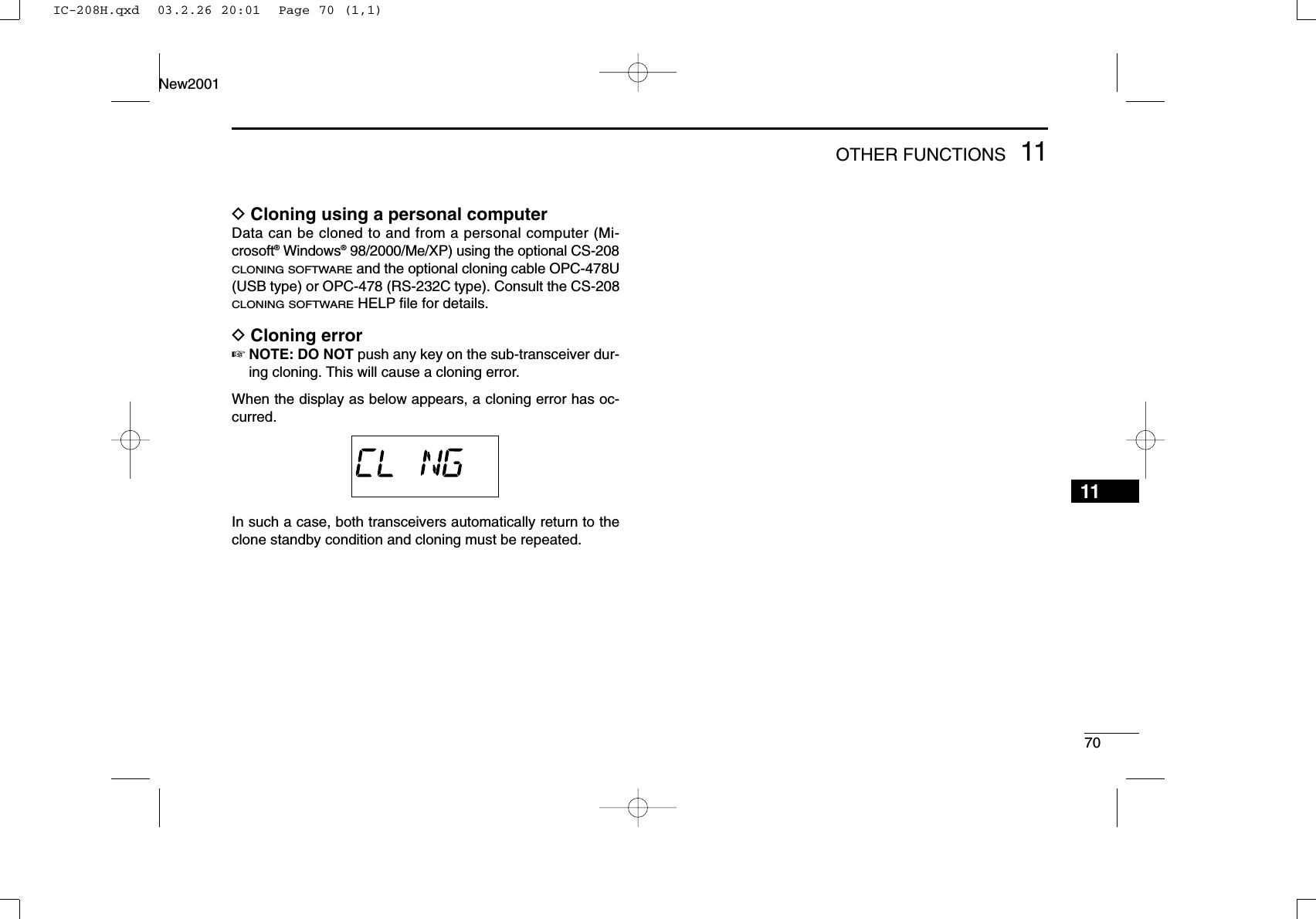
![7111 OTHER FUNCTIONSNew2001■Packet operationDData speedFor packet operation, the transceiver can be set to one of twodata speeds: 1200 bps or 9600 bps.qWhile pushing [SET•LOCK], push [PWR] for 1 sec. to enterinitial set mode.wPush [SET•LOCK] or [S.MW•MW] to select the ‘BPS’item.eRotate [DIAL] to select the desired data speed.rPush [PWR]to exit initial set mode.For 1200 bps operation—•Disconnect the microphone plug from the microphoneconnector during data transmission, otherwise the datasignal and voice signal are simultaneously transmitted.For 9600 bps operation—•When the transceiver is set for 9600 bps data transmis-sion in set mode, the microphone signal is automaticallycut. Therefore, it is not necessary to disconnect the mi-crophone plug from the connector in this case.•When pushing [PTT] during data transmission, data trans-mission is interrupted and voice signals have priority.D1200 bps packet operationqConnect the transceiver and a TNC as illustrated below.wSet the TNC for transmit.eSet transmit delay on the TNC to 30–50.rAdjust the TNC frequency deviation if necessary.•When using a deviation meter:Adjust the output of the TNC so that frequency deviationis in the range ± 3 to ±4 kHz.•When NOT using a deviation meter:A receiver or transceiver is needed to monitor the trans-mission—compare the received audio output level whenreceiving a TNC modulated signal with high level voicesignals using the microphone. Then adjust the TNC mod-ulated signal to a lower level than the voice modulatedsignal.SQLPTTRX AUDIOGNDTX AUDIOTNC sideq DATA INw GNDe PTT Pt AF OUTy P SQLIC-208H.qxd 03.2.26 20:01 Page 71 (1,1)](https://usermanual.wiki/ICOM-orporated/263300/User-Guide-319595-Page-86.png)
![7311 OTHER FUNCTIONSNew2001D9600 bps high speed packet operationThe transceiver supports 2 modes of 9600 bps packet opera-tion: G3RUH and GMSK.qConnect the transceiver and a TNC as illustrated below.wG3RUH mode can handle 16 kinds of modulated waveforms in order to maintain a communication link.eSet transmit delay on the TNC to 30–50.rAdjust the TNC frequency deviation if necessary (see pageat right).•When using the PTT P terminal for packet operation, novoice signals are transmitted from the microphone.•When pushing [PTT] during data transmission, datatransmission is interrupted and the voice signal takes pri-ority.•Read the instructions supplied with your TNC carefullybefore attempting packet operation with the transceiver.•Pin rDATA OUT is for 9600 bps operation only. This pincannot be used for 1200 bps operation.TNC sideSQLPTTRX AUDIOGNDTX AUDIOq DATA INw GNDe PTT P r DATA OUTy P SQLIC-208H.qxd 03.2.26 20:01 Page 73 (1,1)](https://usermanual.wiki/ICOM-orporated/263300/User-Guide-319595-Page-88.png)
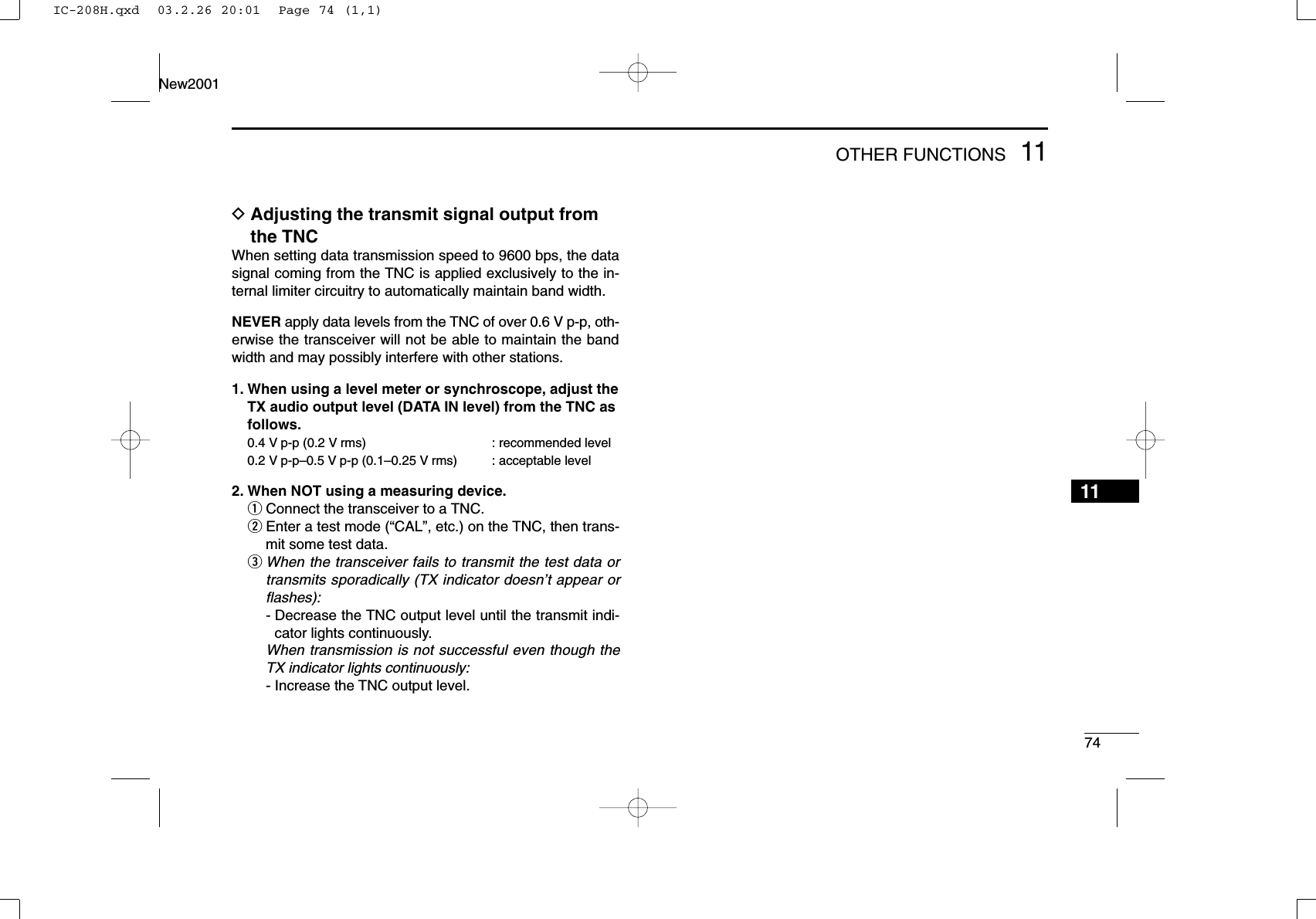
![75MAINTENANCENew2001New200112PROBLEM POSSIBLE CAUSE SOLUTION REF.■Troubleshooting If your transceiver seems to be malfunctioning, please checkthe following points before sending it to a service center.Does not turn on.No sound comes from thespeaker.Sensitivity is low and onlystrong signals are audible.No contact possible withanother station.Repeater cannot be ac-cessed. Frequency cannot be set.Frequency cannot be setvia the microphone.•Power connector has a poor contact.•Polarity of the power connection is reversed.•Blown fuse.•Volume is too low.•The audio mute function is activated.•Squelch is set too high.•A selective call or squelch function is activatedsuch as pocket beep or tone squelch.•Antenna feedline or the antenna connector has apoor contact or is short circuited.•Squelch attenuator function is activated.•The other station is using tone squelch.•The transceiver is set to duplex.•Wrong offset frequency is programmed.•Wrong subaudible tone frequency is programmed.•The frequency lock function is activated.•Priority watch is paused on the watching frequency.•The frequency lock function is activated.•The microphone keypad lock function is activated.•Priority watch is paused on the watching fre-quency.•Check the connector pins.•Re-connect the power cable observing the properpolarity. Replace the fuse if damaged.•Check the cause, then replace the fuse.•Rotate [VOL] clockwise.•Push any switch or key to deactivate it.•Set the squelch level to the threshold.•Turn the appropriate function OFF.•Check, and if necessary, replace the feedline or sol-der the antenna connector again.•Set [SQL] between 10–12 o’clock position.•Turn the tone squelch function ON.•Set to simplex.•Correct the offset frequency.•Correct the subaudible tone frequency.•Turn the function OFF.•Push [M/CALL•PRIO] for 1 sec. to cancel the watch.•Turn the function OFF•Push [FUNC] then [SQLZ#(16KEY-L)] to deactivatethe microphone keypad lock function.•Push [M/CALL•PRIO] for 1 sec. to cancel the watch.—pgs. ??,??p. ??p. ??p. ??p. 1??pgs. ??,??, ??p. ??p. ??p. ??p. ??p. ??p. ??p. ??p. ??p. ??p. ??p. ??IC-208H.qxd 03.2.26 20:01 Page 75 (1,1)](https://usermanual.wiki/ICOM-orporated/263300/User-Guide-319595-Page-90.png)