ICOM orporated 269700 VHF Marine Transceiver User Manual
ICOM Incorporated VHF Marine Transceiver Users Manual
Users Manual
INSTRUCTION MANUAL
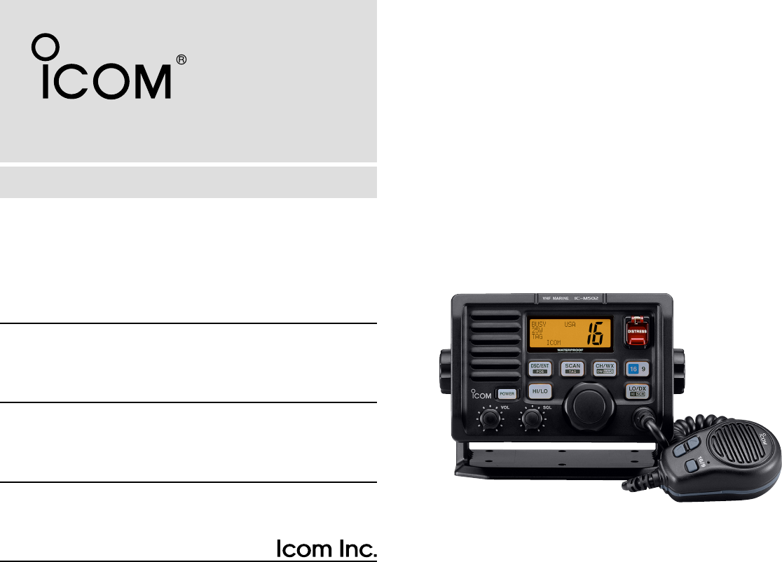
iM502A
VHF MARINE TRANSCEIVER
FOREWORD
Thank you for purchasing this Icom product. The IC-
M502A V
HF MARINE TRANSCEIVER
is designed and built
with Icom’s state of the art technology and craftsman-
ship. With proper care, this product should provide you
with years of trouble-free operation.
We want to take a couple of moments of your time to
thank you for making the IC-M502A your radio of
choice, and hope you agree with Icom’s philosophy of
“technology first.” Many hours of research and devel-
opment went into the design of your IC-M502A.
D
FEATURES
❍Standard 4
″×
6
″
flush mount design
❍Built-in DSC meets RTCM SC101 require-
ment
❍Rugged waterproof construction
❍NMEA Input/Output
❍Optional COMMANDMIC®is connectable
Icom, Icom Inc. and the logo are registered trademarks
of Icom Incorporated (Japan) in the United states, the United
Kingdom, Germany, France, Spain, Russia and/or other coun-
tries. COMMANDMIC is a registered trademark of Icom
Incorporated (Japan) in the United states.
IMPORTANT
READ THIS INSTRUCTION MANUAL
CAREFULLY before attempting to operate the trans-
ceiver.
SAVE THIS INSTRUCTION MANUAL. This
manual contains important safety and operating in-
structions for the IC-M502A.
CLEAN THE TRANSCEIVER AND MICROPHONE
THOROUGHLY WITH FRESH WATER after exposure to
water including salt water, otherwise, the keys and
switches may become inoperable due to salt crystallization.
i
ii
IN CASE OF EMERGENCY
If your vessel requires assistance, contact other vessels and
the Coast Guard by sending a distress call on Ch 16.
Or, transmit your distress call using digital selective calling on
Ch 70.
USING CHANNEL 16
DISTRESS CALL PROCEDURE
1. “MAYDAY MAYDAY MAYDAY.”
2. “THIS IS ...............” (name of vessel)
3. Your call sign or other indication of the vessel (AND 9-
digit DSC ID if you have one).
4. “LOCATED AT ...............” (your position)
5. The nature of the distress and assistance required.
6. Any other information which might facilitate the rescue.
USING DIGITAL SELECTIVE CALLING (Ch 70)
DISTRESS CALL PROCEDURE
1. While lifting up the switch cover, push and hold
[
[DISTRESS
DISTRESS]
]for 5 sec. until you hear 5 short beeps
change to one long beep.
2. Wait for an acknowledgment from a coast station.
• Channel 16 is automatically selected.
3. Push and hold [
[PTT
PTT]
], then transmit the appropriate
information as at above.
NOTE
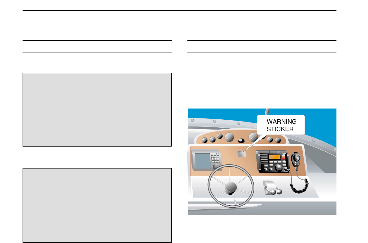
A WARNING STICKER is supplied with the transceiver.
To comply with FCC regulations, this sticker must be affixed in
such a location as to be readily seen from the operating con-
trols of the radio as in the diagram below. Make sure the cho-
sen location is clean and dry before applying the sticker. (p. 42)
EXAMPLE

iii
Icom requires the radio operator to meet the
FCC Requirements for Radio Frequency Expo-
sure. An omnidirectional antenna with gain not
greater than 9 dBi must be mounted a minimum
of 5 meters (measured from the lowest point of
the antenna) vertically above the main deck and all possible
personnel. This is the minimum safe separation distance esti-
mated to meet all RF exposure compliance requirements. This
5 meter distance is based on the FCC Safe Maximum Per-
missible Exposure (MPE) distance of 3 meters added to the
height of an adult (2 meters) and is appropriate for all vessels.
For watercraft without suitable structures, the antenna must
be mounted so as to maintain a minimum of 1 meter vertically
between the antenna, (measured from the lowest point of the
antenna), to the heads of all persons AND all persons must
stay outside of the 3 meter MPE radius.
Do not transmit with radio and antenna when persons are
within the MPE radius of the antenna, unless such persons
(such as driver or radio operator) are shielded from antenna
field by a grounded metallic barrier. The MPE Radius is the
minimum distance from the antenna axis that person should
maintain in order to avoid RF exposure higher than the allow-
able MPE level set by FCC.
FAILURE TO OBSERVE THESE LIMITS MAY ALLOW
THOSE WITHIN THE MPE RADIUS TO EXPERIENCE RF
RADIATION ABSORPTION WHICH EXCEEDS THE FCC
MAXIMUM PERMISSIBLE EXPOSURE (MPE) LIMIT.
IT IS THE RESPONSIBILITY OF THE RADIO OPERATOR
TO ENSURE THAT THE MAXIMUM PERMISSIBLE EXPO-
SURE LIMITS ARE OBSERVED AT ALL TIMES DURING
RADIO TRANSMISSION. THE RADIO OPERATOR IS TO
ENSURE THAT NO BYSTANDERS COME WITHIN THE
RADIUS OF THE MAXIMUM PERMISSIBLE EXPOSURE
LIMITS.
Determining MPE Radius
THE MAXIMUM PERMISSIBLE EXPOSURE (MPE) RA-
DIUS HAS BEEN ESTIMATED TO BE A RADIUS OF
ABOUT 3M PER OET BULLETIN 65 OF THE FCC.
THIS ESTIMATE IS MADE ASSUMING THE MAXIMUM
POWER OF THE RADIO AND ANTENNAS WITH A MAXI-
MUM GAIN OF 9dBi ARE USED FOR A SHIP MOUNTED
SYSTEM.
RADIO OPERATOR WARNING
WARNING

FOREWORD ............................................. i
IMPORTANT .............................................. i
IN CASE OF EMERGENCY ...................... ii
NOTE ........................................................ ii
RADIO OPERATOR WARNING ............... iii
TABLE OF CONTENTS ........................... iv
PRECAUTION .......................................... v
EXPLICIT DEFINITIONS .......................... v
1 OPERATING RULES .................. 1
2 PANEL DESCRIPTION........... 2 – 5
■Front panel ..................................... 2
■Function display .............................. 4
■Microphone...................................... 5
3 BASIC OPERATION ............ 6 – 10
■Channel selection ........................... 6
■Receiving and transmitting ............. 8
■Call channel programming .............. 9
■Channel comments ......................... 9
■
Optional Voice scrambler operation .. 10
4
DUALWATCH/TRI-WATCH
......... 11
■Description .................................... 11
■Operation ...................................... 11
5 SCAN OPERATION ........... 12 – 13
■Scan types .................................... 12
■Setting tag channels ..................... 13
■Starting a scan .............................. 13
6 DSC OPERATION .............. 14 – 35
■MMSI code programming ............. 14
■DSC individual ID ......................... 14
■Position and Time programming ... 16
■Position/Time indication ................ 17
■Distress call .................................. 18
■Transmitting DSC calls ................. 21
■Receiving DSC calls ..................... 29
■Received messages ..................... 32
■DSC Set mode .............................. 34
7 OTHER FUNCTIONS .......... 36–37
■Intercom operation ........................ 36
■Microphone lock function .............. 37
8 SET MODE ........................ 38– 41
■Set mode programming ................ 38
■Set mode items ............................. 39
9 CONNECTIONS AND
MAINTENANCE ................. 42 – 47
■Supplied accessories .................... 42
■Antenna ........................................ 42
■Fuse replacement ......................... 42
■Cleaning ....................................... 42
■Connections .................................. 43
■Mounting the transceiver .............. 44
■Optional unit installation ............... 46
■Dimensions ................................... 47
10 TROUBLESHOOTING .............. 48
11 CHANNEL LIST ........................ 49
12 SPECIFICATIONS AND
OPTIONS ........................... 50 – 51
■Specifications ............................... 50
■Options ......................................... 51
13 HM-127 REMOTE-CONTROL
MICROPHONE ................... 52 – 66
■Panel description .......................... 52
■Function display ............................ 54
■Channel selection ......................... 56
■Receiving and transmitting ........... 57
■Lock functions ............................... 58
■Display backlighting ...................... 58
■Monitor function ............................ 59
■RF attenuator function .................. 59
■Call channel programming ............ 59
■
Optional Voice scrambler operation .. 60
■Dualwatch/Tri-watch operation ..... 60
■Starting a scan .............................. 61
■Setting tag channels ..................... 61
■Set mode programming ................ 62
■Intercom operation ........................ 63
■Channel comments ....................... 63
■HM-127 supplied accessories ...... 64
■Installation .................................... 65
TEMPLATE
iv
TABLE OF CONTENTS 1
2
3
4
5
6
7
8
9
10
11
12
13

v
RWARNING! NEVER connect the transceiver to an AC
outlet. This may pose a fire hazard or result in an electric
shock.
CAUTION: Changes or modifications to this device, not ex-
pressly approved by Icom Inc., could void your authority to
operate this device under FCC regulations.
NEVER connect the transceiver to a power source of more
than 16 V DC or use reverse polarity. This will ruin the trans-
ceiver.
NEVER cut the DC power cable between the DC plug and
fuse holder. If an incorrect connection is made after cutting,
the transceiver may be damaged.
NEVER place the transceiver where normal operation of the
vessel may be hindered or where it could cause bodily injury.
KEEP the transceiver at least 3.3 ft (1 m) away from the
ship’s navigation compass.
DO NOT use or place the transceiver in areas with temper-
atures below –4°F (–20°C) or above +140°F (+60°C) or, in
areas subject to direct sunlight, such as the dashboard.
AVOID the use of chemical agents such as benzine or al-
cohol when cleaning, as they may damage the transceiver
surfaces.
BE CAREFUL! The transceiver rear panel will become
hot when operating continuously for long periods.
Place the transceiver in a secure place to avoid inadvertent
use by children.
BE CAREFUL! The transceiver and optional HM-127 em-
ploy waterproof construction, which corresponds to JIS wa-
terproof specification, Grade 7 (1 m/30 min.). However, once
the transceiver or microphone has been dropped, water-
proofing cannot be guaranteed due to the fact that the case
may be cracked, or the waterproof seal damaged, etc.
EXPLICIT DEFINITIONS
WORD DEFINITION
RRWARNING Personal injury, fire hazard or electric
shock may occur.
CAUTION Equipment damage may occur.
NOTE
If disregarded, inconvenience only. No
risk or personal injury, fire or electric
shock.
PRECAUTION

1
1
OPERATING RULES
DDPRIORITIES
•Read all rules and regulations pertaining to priorities and
keep an up-to-date copy handy. Safety and distress calls
take priority over all others.
•You must monitor Channel 16 when you are not operating
on another channel.
• False or fraudulent distress signals are prohibited and pun-
ishable by law.
DDPRIVACY
• Information overheard but not intended for you cannot law-
fully be used in any way.
• Indecent or profane language is prohibited.
DDRADIO LICENSES
(1) SHIP STATION LICENSE
You must have a current radio station license before using the
transceiver. It is unlawful to operate a ship station which is not
licensed.
Inquire through your dealer or the appropriate government
agency for a Ship-Radiotelephone license application. This
government-issued license states the call sign which is your
craft’s identification for radio purposes.
(2) OPERATOR’S LICENSE
A Restricted Radiotelephone Operator Permit is the license
most often held by small vessel radio operators when a radio
is not required for safety purposes.
The Restricted Radiotelephone Operator Permit must be
posted or kept with the operator. Only a licensed radio opera-
tor may operate a transceiver.
However, non-licensed individuals may talk over a transceiver
if a licensed operator starts, supervises, ends the call and
makes the necessary log entries.
Keep a copy of the current government rules and regulations
handy.
Radio license for boaters (U.S.A. only)
The Telecommunications Act of 1996 permits recreational
boaters to have and use a VHF marine radio, EPIRB, and
marine radar without having an FCC ship station license.
Boaters traveling on international voyages, having an HF
single sideband radiotelephone or marine satellite terminal,
or required to carry a marine radio under any other regula-
tion must still carry an FCC ship station license. For further
information, see the FCC Ship Radio Stations Fact Sheet.
1
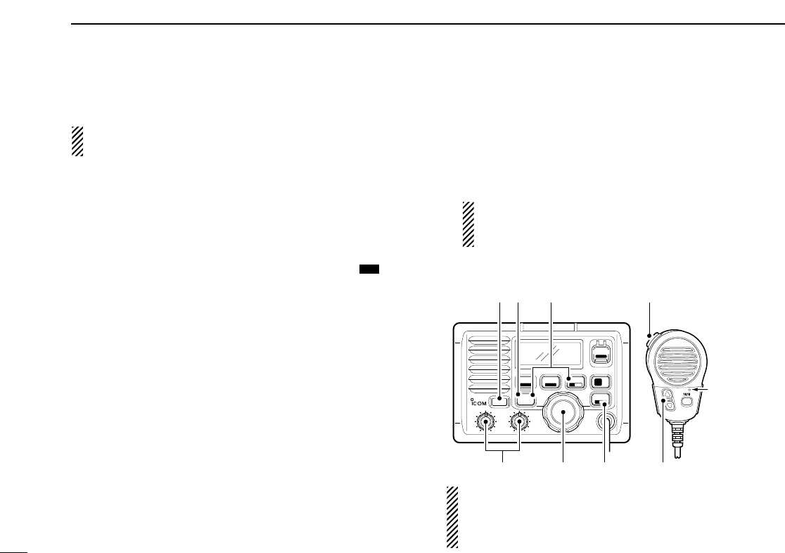
PANEL DESCRIPTION
2
2
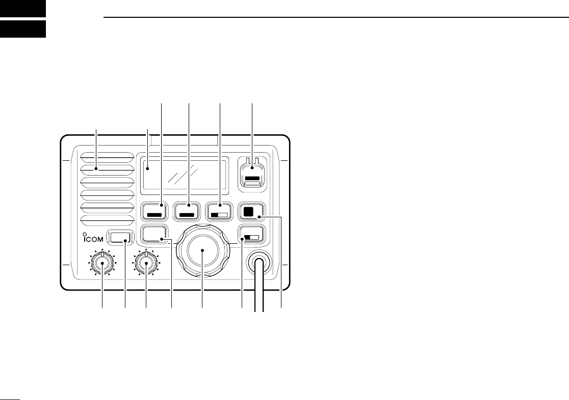
■Front panel
WATERPROOF
SCAN
TAG
DSC/ENT
POS
HI/LO
POWER
VOL
iM502
VHF MARINE
SQL
LO/DX
IC SCR
CH/WX
DW U/I/C 916
DISTRESS
Speaker
Function
display
qwe r t y u
io!0!1
qVOLUME CONTROL [
[VOL
VOL]
](p. 8)
Adjusts the audio level.
wPOWER KEY [
[POWER
POWER]
]
Push to turn the transceiver power ON or OFF.
eSQUELCH CONTROL [
[SQL
SQL]
](p. 8)
Sets the squelch threshold level.
rTRANSMIT POWER KEY [
[HI/LO
HI/LO]
]
➥Toggles power high or low when pushed. (p. 8)
• Some channels are set to low power only.
➥While pushing this key, some keys perform secondary
functions.
tCHANNEL SELECTOR [
[CHANNEL
CHANNEL]
]
➥Rotate [
[CHANNEL
CHANNEL]
]to select the operating channels,
Set mode settings, etc. (pgs. 8, 38)
➥While pushing [
[HI/LO
HI/LO]
], rotate [
[CHANNEL
CHANNEL]
]to adjust
the brightness of the LCD and key backlight. (p. 37)

yATTENUATOR/INTERCOM/SCRAMBLER KEY
[
[LO/DX
LO/DX]
](
(SCR)
SCR)
➥Toggles the Attenuator function ON or OFF when
pushed momentarily. (p. 8)
•“LOCAL” appears when the Attenuator is in use. The order of
indication precedence is “SP OFF,” “LOCAL” and “CALL.”
➥Activates an optional Intercom function when pushed for
1 sec. (p. 36)
➥Calls optional HM-127 REMOTE-CONTROL MICROPHONE
when pushed and held while in Intercom mode. (p. 36)
➥While pushing [
[HI/LO
HI/LO]
], activates an optional Voice
scrambler function. (p. 10)
•The optional Voice scrambler function cannot be used on
Channel 16 and 70.
uCHANNEL 16/CALL CHANNEL KEY [
[9
9]
]
➥Selects Channel 16 when pushed. (p. 6)
➥Selects call channel when pushed for 1 sec. (p. 6)
•“CALL” appears when call channel is selected. “SP OFF”
and “LOCAL” indications have priority.
➥Push for 3 sec. to enter call channel programming con-
dition when call channel is selected. (p. 9)
➥While pushing [
[HI/LO
HI/LO]
], enters channel comments pro-
gramming condition. (p. 9)
➥Enters Set mode when pushed while turning power ON.
(p. 38)
iDISTRESS KEY [
[DISTRESS
DISTRESS]
]
Transmits Distress call when pushed for 5 sec. (p. 18)
oCHANNEL/DUALWATCH/TRI-WATCH KEY
[
[CH/WX
CH/WX]
](
(U/I/C)
U/I/C)
➥Selects and toggles the regular channels and weather
channel when pushed momentarily. (p. 7)
➥While pushing [
[HI/LO
HI/LO]
], selects one of 3 regular chan-
nels in sequence when pushed. (p. 7)
•International, U.S.A. and Canadian channels are available for
regular channels.
➥Starts Dualwatch or Tri-watch when pushed for 1 sec.
(p. 11)
➥Stops Dualwatch or Tri-watch when either is activated.
!0 SCAN KEY [
[SCAN
SCAN]
](
()
)(p. 13)
➥Starts and stops Normal or Priority scan when tag
(scanned) channels are programmed.
➥Push [
[SCAN
SCAN]
](
()
)for 1 sec. to set or cancel the dis-
played channel as a tag (scanned) channel.
➥While pushing [
[HI/LO
HI/LO]
], push for 3 sec. to clear or set
all tag channels.
!1 DSC/POSITION KEY [
[DSC/ENT
DSC/ENT]
](
()
)
➥Selects the DSC menu when pushed. (p. 14)
➥Shows current position and time from a GPS receiver,
etc. when pushed for 1 sec. (p. 17)
POS
TAG
TAG
DW
16
16
IC
PANEL DESCRIPTION
3
2
2
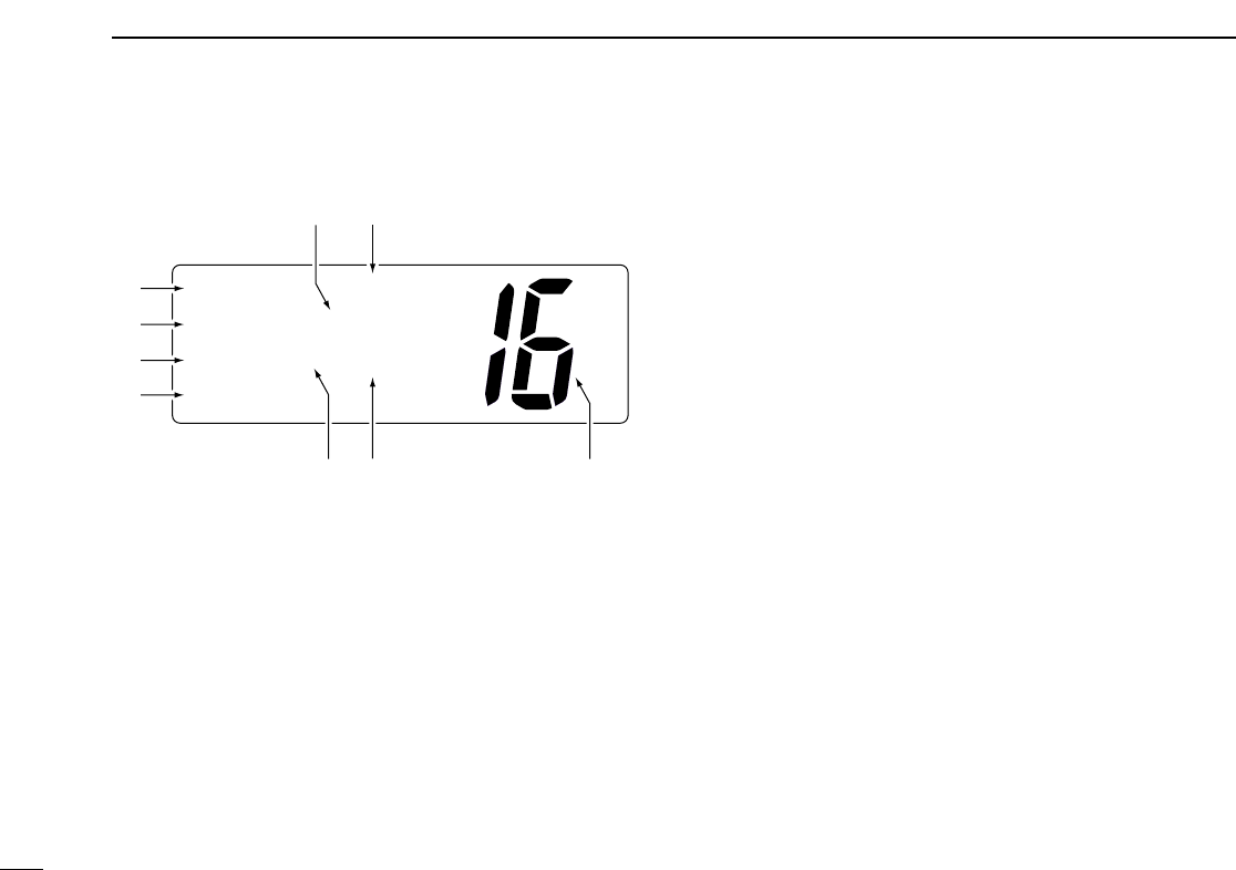
■Function display
qBUSY/TRANSMIT INDICATOR (p. 8)
➥“BUSY” appears when receiving a signal or when the
squelch opens.
➥“TX” appears while transmitting.
wPOWER INDICATOR (p. 8)
➥“25W” appears when high power is selected.
➥“1W” appears when low power is selected.
eTAG CHANNEL INDICATOR (p. 13)
Appears when a tag channel is selected.
rCHANNEL COMMENT INDICATOR
➥Channel comment appears if programmed. (p. 9)
➥“Low Battery” blinks when the battery voltage
drops to approx. 10 V DC or below.
➥“DUAL” appears during Dualwatch; “TRI” appears dur-
ing Tri-watch. (p. 11)
tSCRAMBLER INDICATOR (p. 10)
Appears when an optional Voice scrambler is activated.
INT
CALL
BUSY
25W
TAG SC DUP
CALLING
w
q
e
r
tuy
io
PANEL DESCRIPTION
4
2
5
2
PANEL DESCRIPTION
yDUPLEX INDICATOR (p. 7)
Appears when a duplex channel is selected.
• Duplex channel has a different TX and RX frequency.
uCHANNEL NUMBER READOUT
➥Indicates the selected operating channel number.
“A” appears when a simplex channel is selected. “b” ap-
pears when a receive only channel for a Canadian chan-
nel group is selected. (p. 7)
➥In Set mode, indicates the selected condition. (p. 38)
iCHANNEL GROUP INDICATOR (p. 7)
Indicates whether an International “INT,” U.S.A. “USA,”
Canadian “CAN” or weather “WEATHER” channel is se-
lected.
oCALL CHANNEL INDICATOR
➥“CALL” appears when call channel is selected. (p. 6)
➥“SP OFF” appears when the internal speaker is turned
OFF in Set mode. (p. 40)
➥“LOCAL” appears when the Attenuator is in use. (p. 8)
•The order of indication precedence is “SP OFF,” “LOCAL”
and “CALL.”
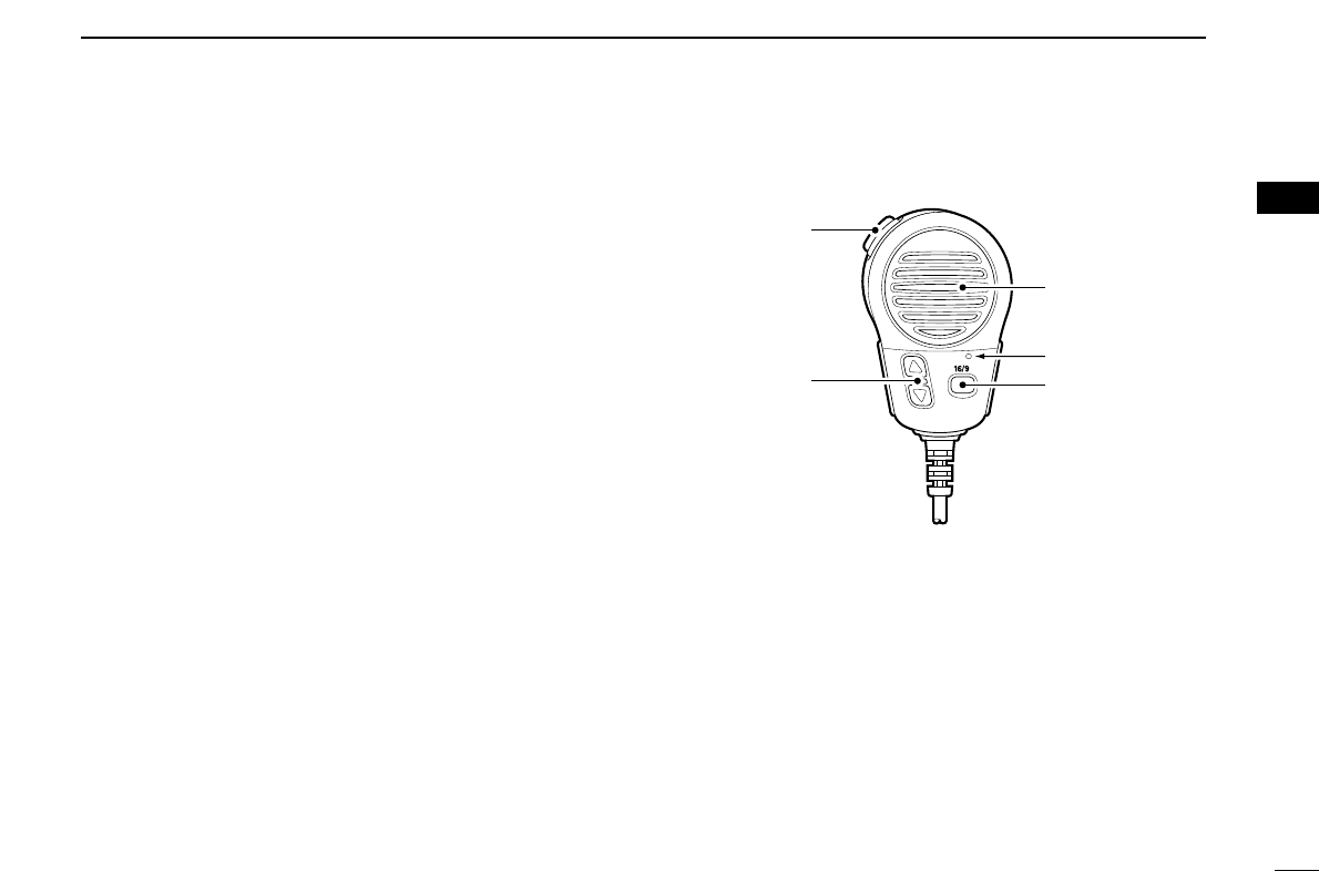
■Microphone
qPTT SWITCH [
[PTT
PTT]
](p. 8)
Push and hold to transmit; release to receive.
wCHANNEL UP/DOWN KEYS [
[YY
YY]
]/[
[ZZ
ZZ]
](pgs. 8, 38)
Push either key to change the operating channel, Set
mode settings, etc.
eCHANNEL 16/CALL CHANNEL KEY [
[16/9
16/9]
]
➥Push to select Channel 16; push for 1 sec. to select call
channel (default is Channel 9). (p. 6)
➥While pushing [
[16/9
16/9]
], turn power ON to toggle the Lock
function ON or OFF. (p. 37)
Speaker
Microphone
w
q
e
2

6
3BASIC OPERATION
■Channel selection
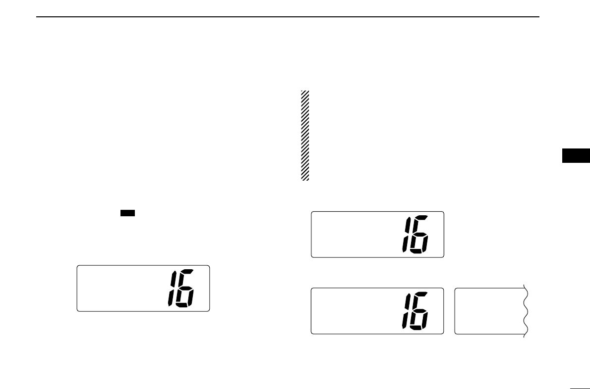
DDChannel 16
Channel 16 is the distress and safety channel. It is used for
establishing initial contact with another station and for emer-
gency communications. Channel 16 is monitored during both
Dualwatch and Tri-watch. While standing by, you must moni-
tor Channel 16.
➥Push [
[9
9]
]momentarily to select Channel 16.
➥Push [
[CH/WX
CH/WX]
]to return to the condition before selecting
Channel 16, or rotate [
[CHANNEL
CHANNEL]
]to select an operating
channel.
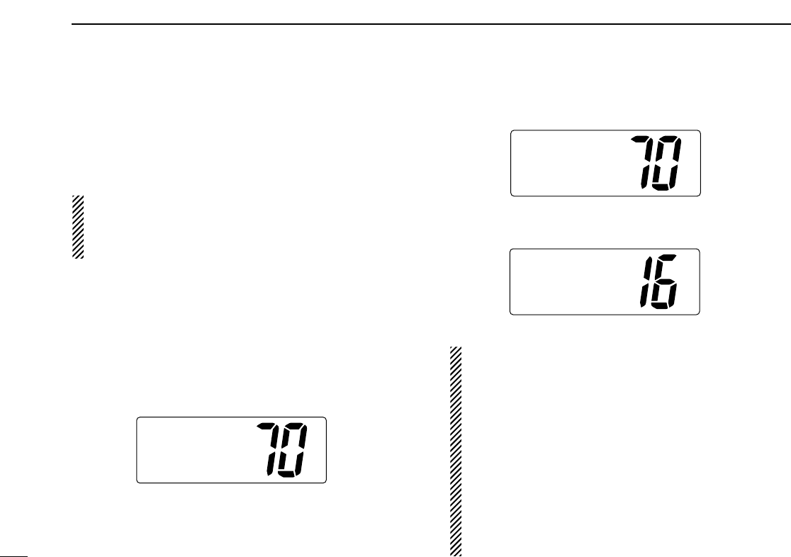
DDChannel 9 (Call channel)
Each regular channel group has a separate leisure-use call
channel. Call channel is monitored during Tri-watch. Call
channels can be programmed (p. 9) and are used to store
your most often used channels in each channel group for
quick recall.
➥Push [
[9
9]
]for 1 sec. to select call channel of the selected
channel group.
•“CALL” and call channel number appear.
• Each channel group may have an independent call channel after
programming a call channel.
➥Push [
[CH/WX
CH/WX]
]to return to the condition before selecting
call channel,or rotate [
[CHANNEL
CHANNEL]
]to select an operating
channel.
Convenient: Using microphone
➥Push [
[16/9
16/9]
]momentarily to select Channel 16.
➥Push [
[16/9
16/9]
]for 1 sec. to select call channel.
➥Push [
[YY
YY]
]/[
[ZZ
ZZ]
]to select any other operating channel.
Push for
1 sec.
INT
25W CALL
TAG
CALLING
916
16
16
INT
25W
TAG
CALLING
Push 916
16
16
3
BASIC OPERATION
7
DDU.S.A., Canadian and International channels
There are 57 U.S.A., 61 Canadian and 57 International chan-
nels. These channel groups may be specified for the operat-
ing area.
qPush [
[CH/WX
CH/WX]
](
(U/I/C)
U/I/C) to select a regular channel.
• If a weather channel appears, push [
[CH/WX
CH/WX]
](
(U/I/C)
U/I/C) again.
wWhile pushing [
[HI/LO
HI/LO]
], push [
[CH/WX
CH/WX]
](
(U/I/C)
U/I/C) to
change the channel group, if necessary.
•U.S.A., International (INT) and Canadian channels can be se-
lected in sequence.
eRotate [
[CHANNEL
CHANNEL]
]to select a channel.
•“DUP” appears for duplex channels.
•“A” appears when a simplex channel is selected. “b” appears
when a receive only channel for a Canadian channel group is se-
lected.
DDWeather channels
There are 10 weather channels. Used for monitoring weather
channels from the NOAA (National Oceanographic and At-
mospheric Administration) broadcasts.
The transceiver can detect a Weather alert tone on the se-
lected weather channel while receiving that channel, during
standby on a regular channel or while scanning. See
“Weather alert” on p. 39.
qPush [
[CH/WX
CH/WX]
]once or twice to select a weather channel.
•“WEATHER” appears when a weather channel is selected.
• “WX ALT” appears when the Weather alert function is in use.
(p. 39)
wRotate [
[CHANNEL
CHANNEL]
]to select a channel.
Push once
or twice When Weather alert is OFF.
WEATHER
When Weather alert is ON.
WXALT
CH/WX
DW U/I/C
Push +
U.S.A. channels
HI/LO CH/WX
DW U/I/C
Canadian channels
CAN
International channels
INT
DUP
USA
DW
DW
DW
3
■Receiving and transmitting
CAUTION: Transmitting without an antenna may dam-
age the transceiver.
qPush [
[POWER
POWER]
]to turn power ON.
wSet the audio and squelch levels.
➥Rotate [
[SQL
SQL]
]fully counterclockwise in advance.
➥Rotate [
[VOL
VOL]
]to adjust the audio output level.
➥Rotate [
[SQL
SQL]
]clockwise until the noise disappears.
eTo change the channel group, push [
[CH/WX
CH/WX]
](
(U/I/C)
U/I/C)
while pushing [
[HI/LO
HI/LO]
]. (p. 7)
rRotate [
[CHANNEL
CHANNEL]
]or push [
[YY
YY]
]/[
[ZZ
ZZ]
]on the microphone
to select the desired channel.
• When receiving a signal, “BUSY” appears and audio is emitted
from the speaker.
• Further adjustment of [
[VOL
VOL]
]may be necessary.
• Use the optional Voice scrambler function for privacy. (p. 10)
tPush [
[LO/DX
LO/DX]
]to turn the receive Attenuator function ON
or OFF, if necessary.
•“LOCAL” appears when the receive Attenuator is in use.
yPush [
[HI/LO
HI/LO]
]to select the output power, if necessary.
•“25W” or “1W” appears when high or low power is selected, re-
spectively.
• Choose low power for short range communications, choose high
power for longer distance communications.
• Some channels are for selecting low power only.
uPush and hold [
[PTT
PTT]
]to transmit, then speak into
∗
(Mi-
crophone).
•“TX” appears.
• Channel 70 cannot be used for transmission other than DSC.
Simplex channels, 3, 21, 23, 61, 64, 81, 82 and 83
CANNOT be lawfully used by the general public in
U.S.A. waters.
iRelease [
[PTT
PTT]
]to receive.
IMPORTANT: To maximize the readability of your trans-
mitted signal, pause a few sec. after pushing [
[PTT
PTT]
], hold
the microphone 2 to 4 inches (5 to 10 cm) from your mouth
and speak into
∗
(Microphone) at a normal voice level.
WATERPROOF
SCAN
TAG
DSC/ENT
POS
HI/LO
POWER
VOL
iM502
VHF MARINE
SQL
LO/DX
IC SCR
CH/WX
DW U/I/C 916
DISTRESS
∗
(Microphone)
q
w
e
rrt
yui
DW
3BASIC OPERATION
8
3
BASIC OPERATION
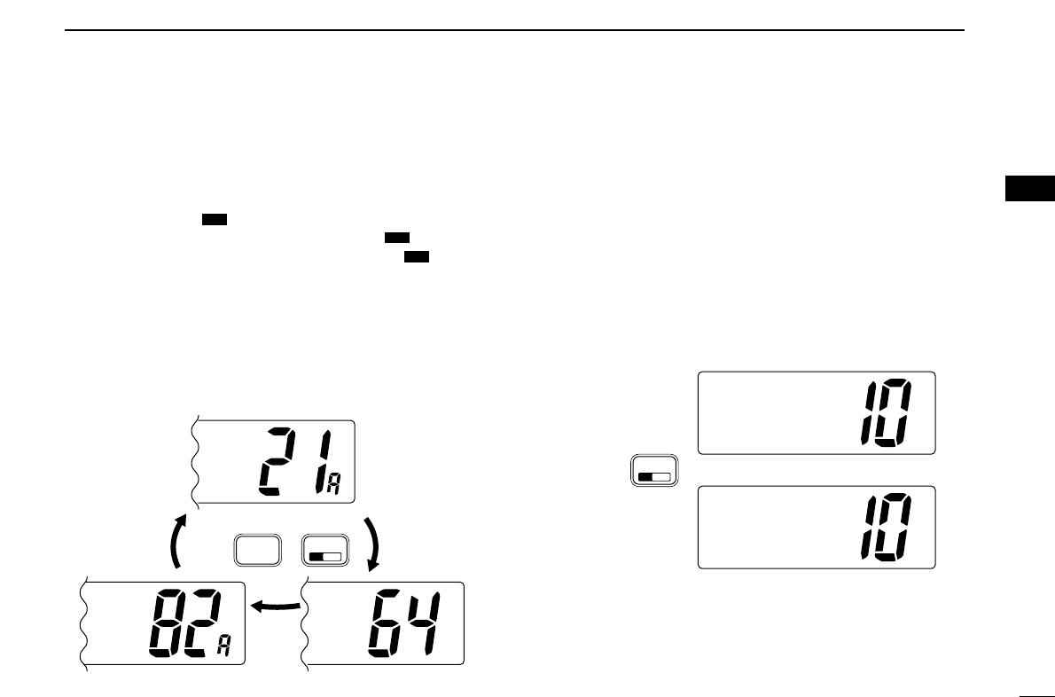
9
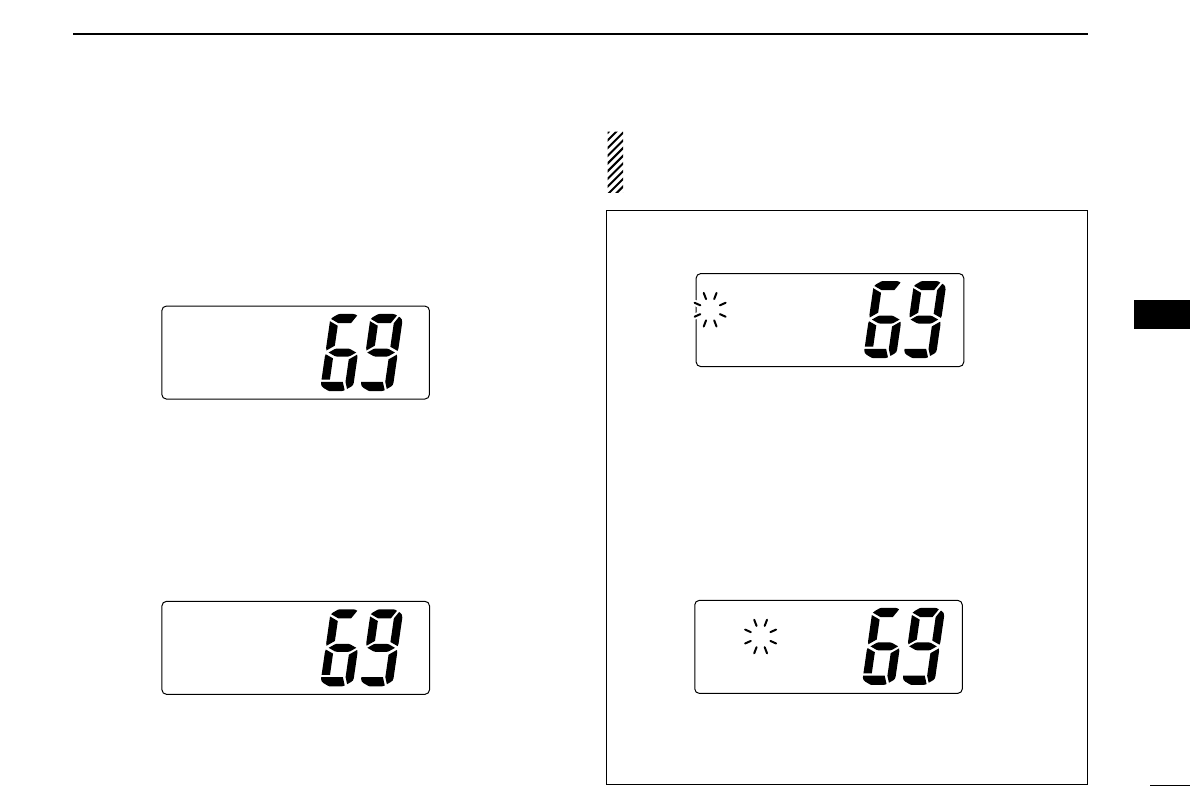
■Call channel programming
Call channel is used to select Channel 9 (default), however,
you can program the call channel with your most often-used
channels in each channel group for quick recall.
qWhile pushing [
[HI/LO
HI/LO]
], push [
[CH/WX
CH/WX]
](
(U/I/C)
U/I/C) one or
more times to select the desired channel group (U.S.A., In-
ternational, Canada) to be programmed.
wPush [
[9
9]
]for 1 sec. to select call channel of the se-
lected channel group.
•“CALL” and call channel number appear.
• The order of indication precedence is “SP OFF,” “LOCAL” and
“CALL.”
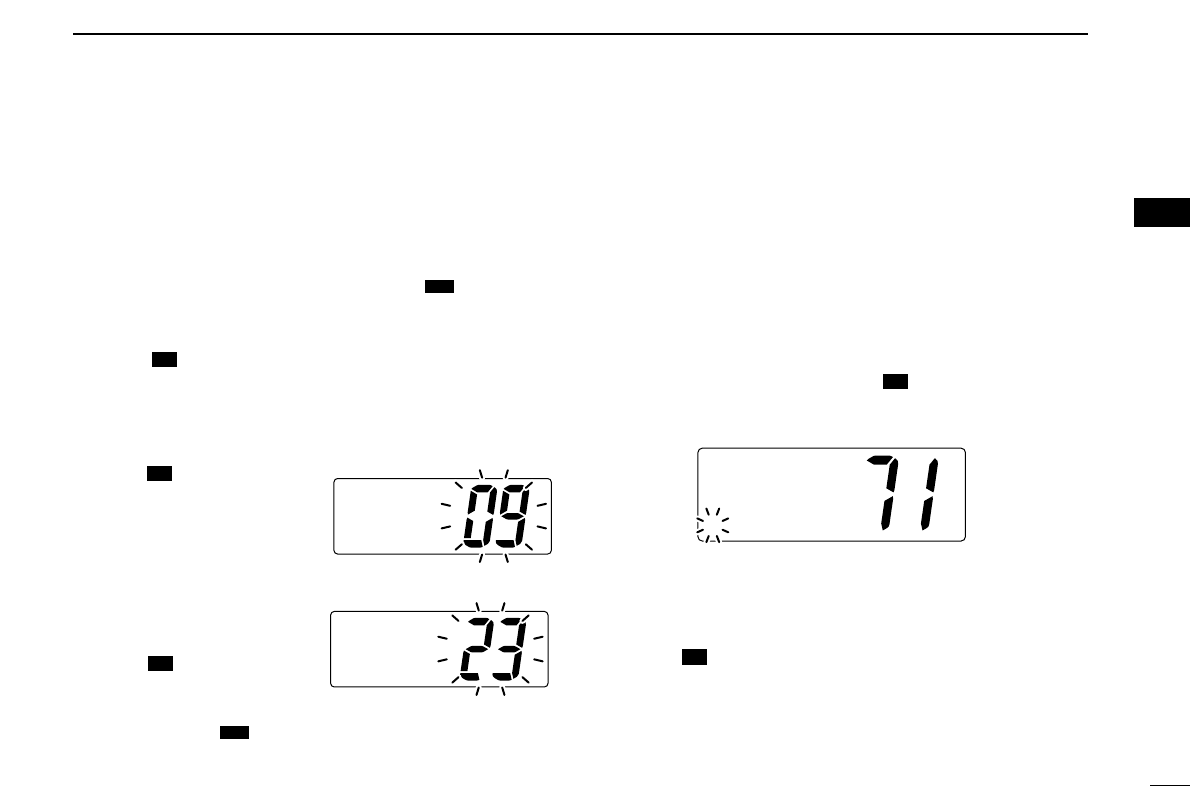
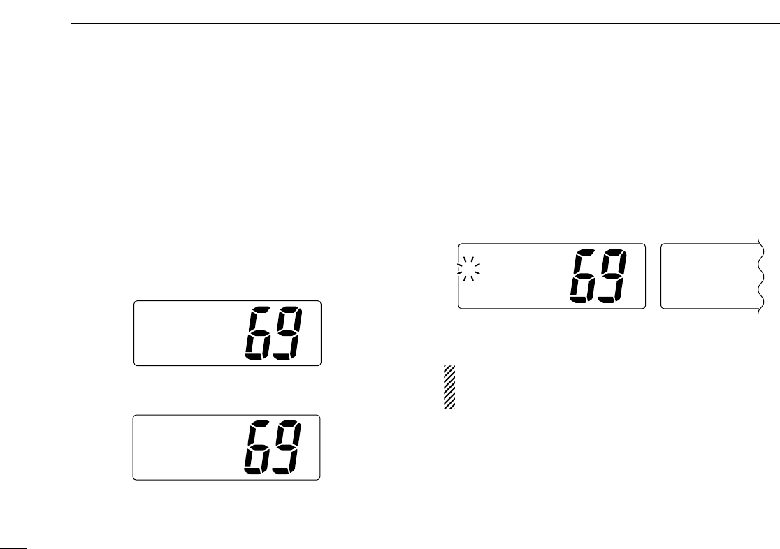
e
Push [
[9
9]
]again for 3 sec.
(until a long beep changes
to 2 short beeps) to enter
call channel programming
condition.
• Channel number starts blinking.
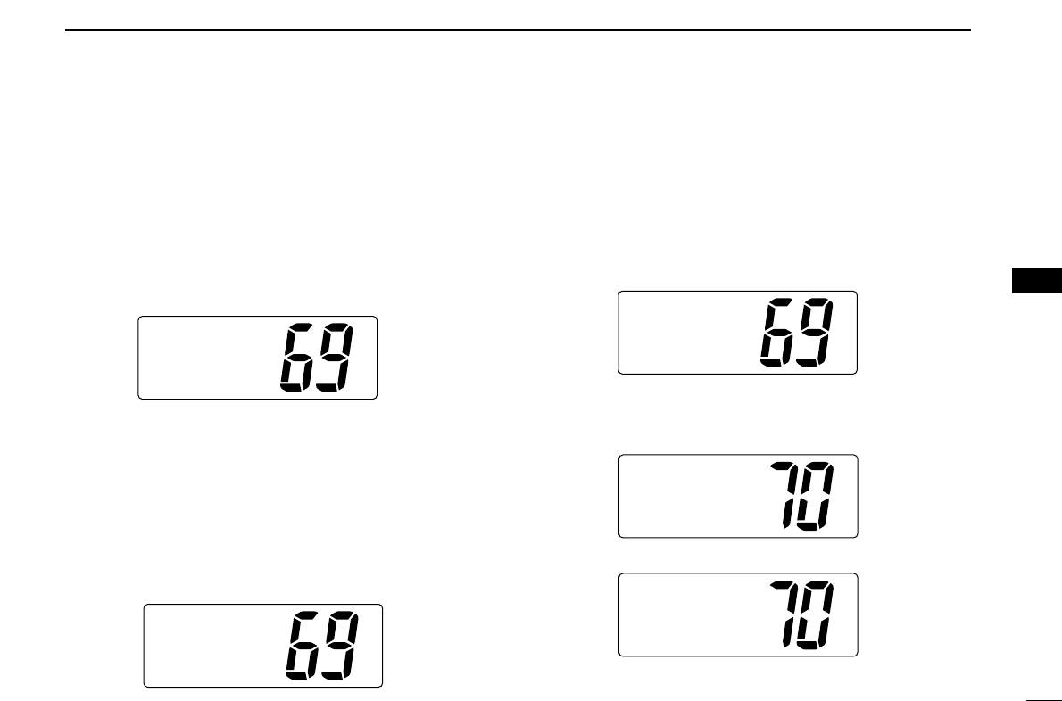
rRotate [
[CHANNEL
CHANNEL]
]to se-
lect the desired channel.
tPush [
[9
9]
]to program the
displayed channel as call
channel.
• Push [
[CH/WX
CH/WX]
](
(U/I/C)
U/I/C) to cancel.
• The channel number stops blinking.
■Channel comments
Memory channels can be labeled with alphanumeric com-
ments of up to 10 characters each.
Capital letters, small letters, numerals, some symbols (! " #
$ % & ' ( ) * + , - ./ =) and space can be used.
qSelect the desired channel.
• Cancel dualwatch, Tri-watch or scan in advance.
wWhile pushing [
[HI/LO
HI/LO]
], push [
[9
9]
]to edit the channel
comment.
• A cursor appears and blinks.
eSelect the desired character by rotating [
[CHANNEL
CHANNEL]
]or
by pushing [
[YY
YY]
]/[
[ZZ
ZZ]
]on the microphone.
• Push [
[CH/WX
CH/WX]
]or [
[SCAN
SCAN]
]to move the cursor forward or back-
ward, respectively.
rPush [
[9
9]
]to input and set the comment.
• Push [
[HI/LO
HI/LO]
]to cancel.
• The cursor disappears.
tRepeat steps qto rto program the other channels, if de-
sired.
16
16
INT
25W
TAG
äLEASURE
16
16
DW
16
16
16
16
16
16
DW
INT
25W CALL
TAG
CALLING
INT
25W CALL
DUPTAG
INTL
3
10
3BASIC OPERATION
■Optional Voice scrambler operation
DDActivating the Scrambler
The optional Voice scrambler provides private communica-
tions. In order to receive or send scrambled transmissions
you must first activate the Scrambler function. To activate the
function, an optional UT-98 or UT-112 is necessary. See p. 41
for setting the scrambler unit. Ask your dealer for details.
The Scrambler function automatically turns OFF when
Channel 16 or 70 is selected.
q
Select an operating channel other than Channel 16 or 70.
wWhile pushing [
[HI/LO
HI/LO]
], push [
[LO/DX
LO/DX]
](
(SCR)
SCR) to turn
the optional Scrambler function ON.
•“SC” appears.
eTo turn the Scrambler function OFF, repeat step w.
•“SC” disappears.
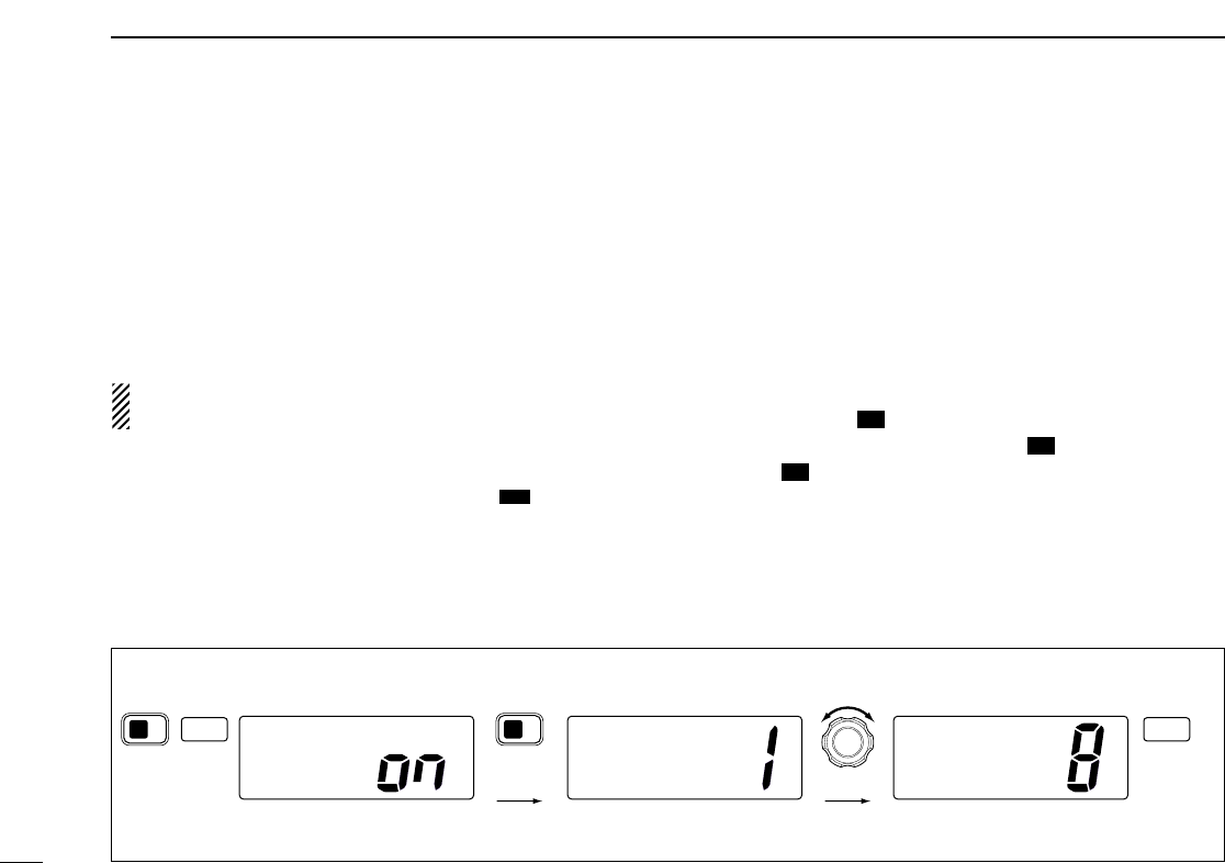
DDProgramming scrambler codes
There are 128 or 32 codes (0 to 127 or 1 to 32) available for
programming when the optional UT-98 or UT-112 is installed.
In order to understand one another, all transceivers in your
group must have the same scramble code. This function may
not be available depending on dealer setting.
qTurn power OFF.
wWhile pushing [
[9
9]
], turn power ON to enter Set mode.
eAfter the display appears, release [
[9
9]
].
rPush [
[9
9]
]one or more times to select the scrambler
code.
•“Scrambler Code” appears.
tRotate [
[CHANNEL
CHANNEL]
]to select the desired scrambler code.
yTurn power OFF, then ON again to exit Set mode.
16
16
16
16
16
16
IC
SetMode
Beep
SetMode
Scrambler
Code
SetMode
Scrambler
Code
Enter Set mode Turn OFF
POWER POWER
+
916 916
Select code
Push one or
more times.
Set mode Scrambler code item
[Example]: Programming scrambler code 8.
11
4
DUALWATCH/TRI-WATCH
■Description
Dualwatch monitors Channel 16 while you are receiving an-
other channel; Tri-watch monitors Channel 16 and call chan-
nel while receiving another channel.
■Operation
qSelect Dualwatch or Tri-watch in Set mode. (p. 39)
wSelect the desired operating channel.
ePush [
[CH/WX
CH/WX]
](
(U/I/C)
U/I/C) for 1 sec. to start Dualwatch or
Tri-watch.
•“DUAL” appears during Dualwatch; “TRI” appears during Tri-
watch.
• A beep tone sounds when a signal is received on Channel 16.
r
To cancel Dualwatch or Tri-watch, push [
[CH/WX
CH/WX]
](
(U/I/C)
U/I/C)
again.
DW
DW
[Example]: Operating Tri-watch on INT Channel 25.
DUALWATCH/TRI-WATCH SIMULATION
•If a signal is received on Channel 16, Dualwatch/Tri-watch
pauses on Channel 16 until the signal disappears.
•If a signal is received on call channel during Tri-watch, Tri-watch
becomes Dualwatch until the signal disappears.
•To transmit on the selected channel during Dualwatch/Tri-watch,
push and hold [
[PTT
PTT]
].
Dualwatch Tri-watch
Call channel
INT
25W
DUP
16
TAG
TRI
INT
25W
DUP
16
TAG
TRI
BUSY INT
25W CALL
16
TAG
TRI
BUSY INT
25W
DUP
16
TAG
TRI
Tri-watch starts.
Signal is received
on call channel.
Signal received on
Channel 16 takes
priority.
Tri-watch resumes
after the signal
disappears.
4
3
5SCAN OPERATION
12
■Scan types
Scanning is an efficient way to locate signals quickly over a
wide frequency range. The transceiver has Priority scan and
Normal scan.
When the Weather alert function is in use, the selected
weather channel is checked while scanning. (p. 39)
Set the tag channels (scanned channel) before scanning.
Clear the tag channels which inconveniently stop scanning,
such as those for digital communication use.
Choose Priority or Normal scan in Set mode. (p. 39)
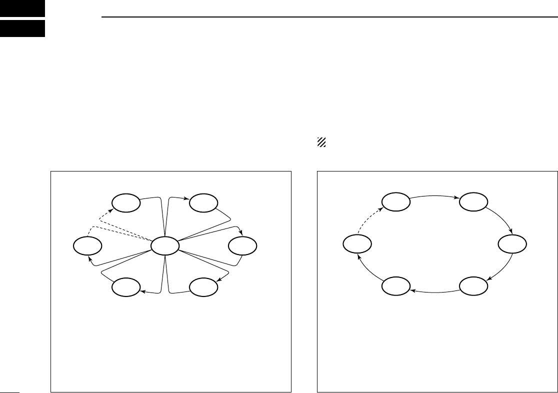
NORMAL SCAN
Normal scan, like Priority scan, searches through all tag
channels in sequence. However, unlike Priority scan,
Channel 16 is not checked unless Channel 16 is set as a
tag channel.
CH 01 CH 02
CH 06
CH 05 CH 04
CH 03
PRIORITY SCAN
Priority scan searches through all tag channels in se-
quence while monitoring Channel 16. When a signal is de-
tected on Channel 16, scan pauses until the signal disap-
pears; when a signal is detected on a channel other than
Channel 16, scan becomes Dualwatch until the signal dis-
appears.
CH 06
CH 01
CH 16
CH 02
CH 05 CH 04
CH 03
5
SCAN OPERATION
13
INT
25W
DUPTAG
INTL
INT
25W
DUPTAG
Normalscan
BUSY INT
25W
DUPTAG
Normalscan
SCAN
TAG
Push
Scan starts. When a signal is received
[Example]: Starting a Normal scan.
■Setting tag channels
For more efficient scanning, add desired channels as tag
channels or clear tag channels for unwanted channels. Chan-
nels not tagged will be skipped during scanning. Tag chan-
nels can be assigned to each channel group (U.S.A., Interna-
tional, Canada) independently.
qWhile pushing [
[HI/LO
HI/LO]
], push [
[CH/WX
CH/WX]
](
(U/I/C)
U/I/C) one or
more times to select the desired channel group.
wSelect the desired channel to be set as a tag channel.
ePush [
[SCAN
SCAN]
](
()
)for 1 sec. to set the displayed channel
as a tag channel.
•“TAG” appears in the display.
rTo cancel the tag channel setting, repeat step e.
•“TAG” disappears.
Convenient: Clearing (setting) all tagged channels
➥While pushing [
[HI/LO
HI/LO]
], push [
[SCAN
SCAN]
](
()
)for 3 sec. (until
a long beep changes to 2 short beeps) to clear all tag
channels setting in the channel group.
• Repeat above procedure to set all tag channels.
■Starting a scan
Set scan type (Priority or Normal scan) and scan resume
timer in advance using Set mode. (p. 39)
qSet tag channels as described at left.
wMake sure the squelch is closed to start a scan.
eWhile pushing [
[HI/LO
HI/LO]
], push [
[CH/WX
CH/WX]
](
(U/I/C)
U/I/C) one or
more times to select the channel group, if desired.
r
Push
[
[SCAN
SCAN]
]
to start Priority or Normal scan.
•“Pri Scan 16” or “Normal Scan” appears in the function
display.
•When a signal is detected, scan pauses until the signal disap-
pears or resumes after pausing 5 sec. according to Set mode
setting. (Channel 16 is still monitored during Priority scan.)
•Rotate [
[CHANNEL
CHANNEL]
]to check the scanning tag channels, to
change the scanning direction or resume the scan manually.
•“16” blinks and a beep tone sounds when a signal is received
on Channel 16 during Priority scan.
tTo stop the scan, push [
[SCAN
SCAN]
].
DW
TAG
TAG
DW
5
14
6DSC OPERATION
■MMSI code programming
The 9-digit MMSI (Maritime Mobile Service Identity: DSC self
ID) code can be programmed at power ON.
This function is not available when the MMSI code has
been programmed by the dealer. This code programming
can be performed only twice.
qTurn power OFF.
wWhile pushing [
[DSC/ENT
DSC/ENT]
], turn power ON to enter MMSI
code programming condition.
eAfter the display appears, release [
[DSC/ENT
DSC/ENT]
].
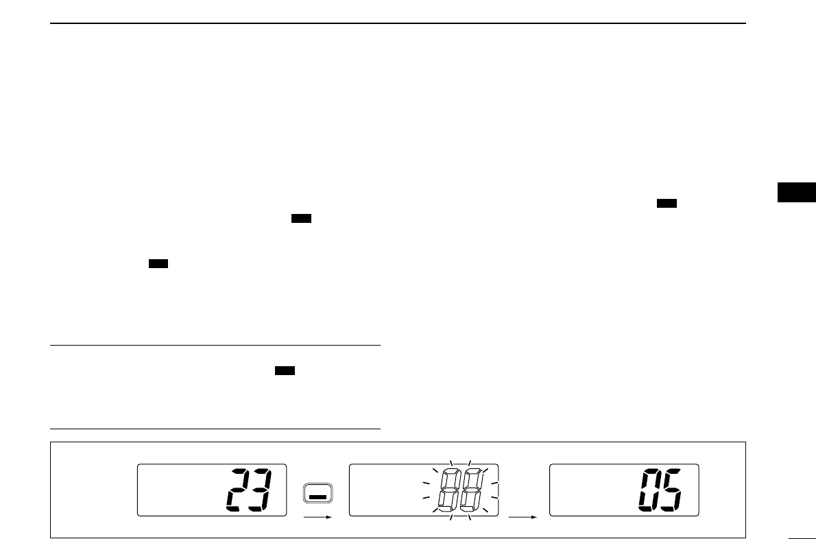
rEdit the specific MMSI code by rotating [
[CHANNEL
CHANNEL]
].
• Push [
[CH/WX
CH/WX]
]or [
[SCAN
SCAN]
]to move the cursor forward or back-
ward, respectively.
tInput the 9 digit codes, then push [
[DSC/ENT
DSC/ENT]
]to set the
code.
• Returns to the normal operation.
■DSC individual ID
A total of 40 DSC address IDs can be programmed and
named with up to 10 characters.
DDProgramming Address ID/Group ID
qPush [
[DSC/ENT
DSC/ENT]
]to enter the DSC menu.
wRotate [
[CHANNEL
CHANNEL]
]to select “Set up,” push
[
[DSC/ENT
DSC/ENT]
].
e
Rotate
[
[CHANNEL
CHANNEL]
]
to select “Add ID,” push
[
[DSC/ENT
DSC/ENT]
]
.
Setup
˘AddID
DeleteID
OffsetTime
SelItem
POSReport
DTRSSet
˘Setup
SetMMSI
ä23456789
15
6
DSC OPERATION
rSet the individual ID and ID name.
• Edit the 9 digits of the appropriate distress ID by using [
[CHAN
CHAN-
-
NEL
NEL]
].
-Push [
[CH/WX
CH/WX]
]or [
[SCAN
SCAN]
]to move the cursor forward or
backward, respectively.
1st digit ‘0’ is fixed for a group ID. Thus an address ID input
cannot start with ‘0.’ When you input 1st digit ‘0’ and other 8
digits, the ID is automatically registered as a group ID.
tPush [
[DSC/ENT
DSC/ENT]
]to program and exit the condition to the
normal operation.
DDDeleting Address ID/Group ID
qPush [
[DSC/ENT
DSC/ENT]
]to enter the DSC menu.
wRotate [
[CHANNEL
CHANNEL]
]to select “Set up,” push
[
[DSC/ENT
DSC/ENT]
].
eRotate [
[CHANNEL
CHANNEL]
]to select “Delete ID,” push
[
[DSC/ENT
DSC/ENT]
].
•When no address ID is programmed, the transceiver exits the
DSC menu automatically.
rRotate [
[CHANNEL
CHANNEL]
]to select the desired ID name for
deleting.
tThe delete confirmation display will appear when
[
[DSC/ENT
DSC/ENT]
]is pushed.
• Push [
[HI/LO
HI/LO]
]to delete ID and exit the DSC Menu.
• Push [
[DSC/ENT
DSC/ENT]
]to cancel deleting and exit the DSC Menu.
DeleteID
Ricky
˘Bill
Tom
Setup
AddID
˘DeleteID
OffsetTime
AddID
ID:
NAME:
6
16
6DSC OPERATION
■
Position and Time programming
A distress call should include the ship’s position and time. If
no GPS is connected, your position and UTC (Universal Time
Coordinated) time should be input manually. They are in-
cluded automatically when a GPS receiver (NMEA0183 ver.
2.0 or 3.01) is connected.
This manual programming is not available when a GPS re-
ceiver (NMEA0183 ver. 2.0 or 3.01) is connected.
qPush [
[DSC/ENT
DSC/ENT]
]to enter the DSC menu.
w
“POS Input” is selected automatically, push [
[DSC/ENT
DSC/ENT]
].
eEdit the digit of your latitude data by using [
[CHANNEL
CHANNEL]
].
• Push [
[CH/WX
CH/WX]
]or [
[SCAN
SCAN]
]to move the cursor forward or back-
ward, respectively.
• After editing latitude data, select “N”; North latitude or “S”; South
latitude.
• Push [
[HI/LO
HI/LO]
]to clear the position data.
r
Edit the digit of your longitude data by using
[
[CHANNEL
CHANNEL]
]
.
• Push [
[CH/WX
CH/WX]
]or [
[SCAN
SCAN]
]for cursor movement.
•After editing longitude data, select “E”; East longitude or “W”;
West longitude.
• Push [
[HI/LO
HI/LO]
]to clear the position data.
tPush [
[DSC/ENT
DSC/ENT]
]to set the position and advance to the
time setting condition.
•Push [
[9
9]
]or [
[LO/DX
LO/DX]
]to abandon the setting and exit the
DSC menu.
yEdit the digit of the current UTC time by using [
[CHAN
CHAN-
-
NEL
NEL]
].
• Push [
[CH/WX
CH/WX]
]or [
[SCAN
SCAN]
]for cursor movement.
• Push [
[HI/LO
HI/LO]
]to clear the time data.
uPush [
[DSC/ENT
DSC/ENT]
]to set the time, and exit the DSC menu.
•Push [
[9
9]
]or [
[LO/DX
LO/DX]
]to abandon the setting and exit the
DSC menu.
16
16
Inputtime
UTC:
Null˘[H/L]
16
16
InputPOS
°.
-°.
Null˘[H/L]
17
6
DSC OPERATION
■Position/Time indication
When a GPS receiver (NMEA0183 ver. 2.0 or 3.01) is con-
nected, the transceiver displays the current position and time.
When no GPS receiver is connected, the transceiver displays
the manually entered position and time.
A GPS receiver appropriate for the IC-M502A is not supplied
from Icom. A GPS receiver with NMEA0183 ver. 2.0 or 3.01
format is required for position indication. Ask your dealer
about suitable GPS receivers.
➥Push [
[DSC/ENT
DSC/ENT]
](
()
)for 1 sec. to display the current po-
sition and time.
•“MNL” (manual) appears instead of the “GPS” indication when
no GPS is connected and the position/time data is entered man-
ually.
➥When connecting GPS receiver is compatible several
sentence formatteres, the order of input precedence is
‘RMC,’ ‘GGA,’ ‘GNS’ and ‘GLL.’
➥When sentence formatter ‘RMC’ is received, time indi-
cation includes a date, and UTC time only.
➥“??” may blink instead of position and time indications
when the GPS data is invalid, or has not been manually
updated after 4 hours.
34°34.123N
135°34.123E
JUL1711:47
CALLING
34°34.123N
135°34.123E
GPSUTC11:47
CALLING
34°34.123N
135°34.123E
GPSLOC01:47
CALLING
• Sentence formatter ‘RMC’
• Sentence formatteres ‘GGA,’ ‘GNS,’ ‘GLL’
No offset time Offset time is
–10 hours. (p.34)
34°34.123N
135°34.123E
GPSUTC12:34
CALLING
POS
6
18
6DSC OPERATION
■Distress call
A Distress call should be transmitted, if in the opinion of the
Master, the ship or a person is in distress and requires imme-
diate assistance.
NEVER USE THE DISTRESS CALL WHEN
YOUR SHIP IS NOT IN AN EMERGENCY. A
DISTRESS CALL CAN BE USED ONLY WHEN
IMMEDIATE HELP IS NEEDED.
DDSimple call
qConfirm no Distress call is being received.
wWhile lifting up the switch cover, push [
[DISTRESS
DISTRESS]
]for 5
sec. to transmit the Distress call.
•Emergency channel (Ch 70) is automatically selected and the
Distress call is transmitted.
• When no GPS is connected, input your position and UTC time, if
possible.
eAfter transmitting the call, the transceiver waits for an ac-
knowledgment call on Ch 70.
•The Distress call is automatically transmitted every 3.5 to 4.5
minutes.
rAfter receiving the acknowledgment, reply using the mi-
crophone.
➥A distress alert contains (default);
• Kind of distress : Undesignated distress
• Position data : GPS or manual input position data held for
23.5 hrs or until the power is turned OFF.
➥The Distress call is repeated every 3.5–4.5 min., until re-
ceiving an ‘acknowledgement.’
➥Push [
[DISTRESS
DISTRESS]
]to transmit a renewed Distress call,
if required.
➥Push any key (except [
[DISTRESS
DISTRESS]
]) to cancel the ‘Call
repeat’ mode.
➥“??” may blink instead of position and time indications
when the GPS data is invalid, or has not been manually
updated after 4 hours.
<TokyoCG
DistressACK
Received
Distress
Completed
WaitforACK
DistressTX
35°23.123N
135°35.123E
GPSUTC12:34
19
6
DSC OPERATION
DDNormal call
The nature of the Distress call should be included in the Dis-
tress call.
qPush [
[DSC/ENT
DSC/ENT]
]to enter the DSC menu.
wRotate [
[CHANNEL
CHANNEL]
]to select “DTRS Set,” push
[
[DSC/ENT
DSC/ENT]
].
eRotate [
[CHANNEL
CHANNEL]
]to select the nature of the distress,
push [
[DSC/ENT
DSC/ENT]
].
•‘Undesignated,’ ‘Explosion,’ ‘Flooding,’ ‘Collision,’ ‘Grounding,’
‘Capsizing,’ ‘Sinking,’ ‘Adrift (Disable adrift),’ ‘Abandoning (Aban-
doning ship),’ ‘Piracy (Piracy attack)’ and ‘MOB (Man overboard)’
are available.
• The selected nature of the distress is stored for 10 minutes after
programming is finished.
When a GPS receiver (NMEA0183 ver. 2.0 or 3.01) is con-
nected,
next steps r, t(
Current position/time program-
ming) do not appear. Go to step y. (next page)
SelNature
˘Explosion
Undesign
Flooding
SelItem
POSReport
RCVCalls
˘DTRSSet
6
rThe position information appears. Set the current posi-
tion, push [
[DSC/ENT
DSC/ENT]
].
• Edit the digit of your position data by using [
[CHANNEL
CHANNEL]
].
-Push [
[CH/WX
CH/WX]
]or [
[SCAN
SCAN]
]for cursor movement.
-After editing latitude data, select “N”; North latitude or “S”;
South latitude.
-After editing longitude data, select “E”; East longitude or “W”;
West longitude.
- Push [
[HI/LO
HI/LO]
]to clear the position data.
tThe time information appears. Set the current UTC time,
push [
[DSC/ENT
DSC/ENT]
].
• Edit the digit of the current UTC time by using [
[CHANNEL
CHANNEL]
].
-Push [
[CH/WX
CH/WX]
]or [
[SCAN
SCAN]
]for cursor movement.
- Push [
[HI/LO
HI/LO]
]to clear the time data.
Inputtime
UTC:
Null˘[H/L]
InputPOS
°.
-°.
Null˘[H/L]

20
6DSC OPERATION
yPush [
[DISTRESS
DISTRESS]
]for 5 sec. to transmit the Distress call.
uAfter transmitting the call, the transceiver waits for an ac-
knowledgment call on Ch 70.
•The Distress call is automatically transmitted every 3.5 to 4.5
minutes.
iAfter receiving the acknowledgment, reply using the mi-
crophone.
➥A distress alert contains;
• Kind of distress : Selected nature of the distress.
• Position data: GPS or manual input position data held for 23.5
hrs or until the power is turned OFF.
➥The Distress call is repeated every 3.5–4.5 min., until re-
ceiving an ‘acknowledgement.’
➥Push [
[DISTRESS
DISTRESS]
]to transmit a renewed Distress call,
if required.
➥Push any key (except [
[DISTRESS
DISTRESS]
]) to cancel the ‘Call
repeat’ mode.
➥“??” may blink instead of position and time indications
when the GPS data is invalid, or has not been manually
updated after 4 hours.
<TokyoCG
DistressACK
Received
Distress
Completed
WaitforACK
SetisOK
Push[DTRS]
for5sec
21
6
DSC OPERATION
6
■Transmitting DSC calls
DDTransmitting Individual call
The Individual call function allows you to transmit a DSC sig-
nal to a specific ship only.
qPush [
[DSC/ENT
DSC/ENT]
]to enter the DSC menu.
wRotate [
[CHANNEL
CHANNEL]
]to select “Individual,” push
[
[DSC/ENT
DSC/ENT]
].
e
Rotate
[
[CHANNEL
CHANNEL]
]
to select the desired pre-programmed
individual address or “Manual Input,” push
[
[DSC/ENT
DSC/ENT]
]
.
• The ID code for the Individual call can be set in advance. (p. 14)
•When “Manual Input” is selected, set the 9-digit ID code
(1st digit must not be ‘0’) for the individual you wish to call by
using [
[CHANNEL
CHANNEL]
].
-Push [
[CH/WX
CH/WX]
]or [
[SCAN
SCAN]
]for cursor movement.
- After 9-digit is input, push [
[DSC/ENT
DSC/ENT]
]to set the ID code.
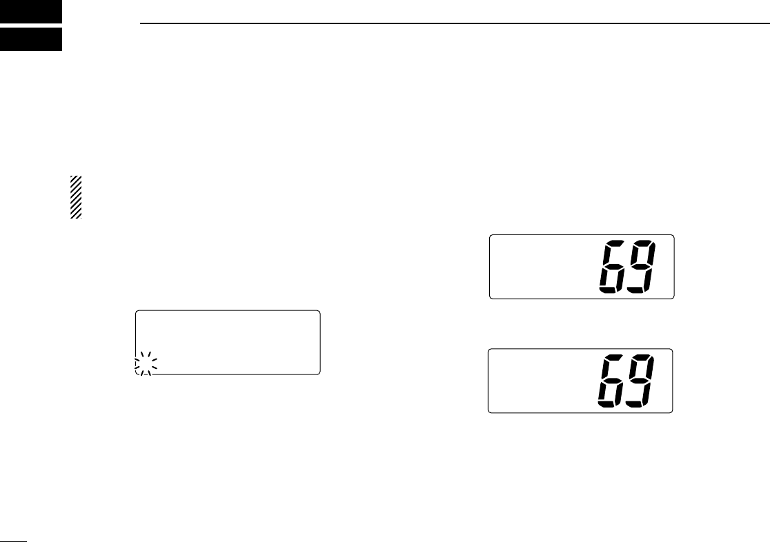
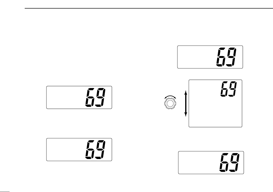
rRotate [
[CHANNEL
CHANNEL]
]to select a desired intership channel
or “Manual Input,” push [
[DSC/ENT
DSC/ENT]
].
•When “Manual Input” is selected, rotate
[
[CHANNEL
CHANNEL]
]
to
select the desired channel other than Channel 70, push
[
[DSC/ENT
DSC/ENT]
]
.
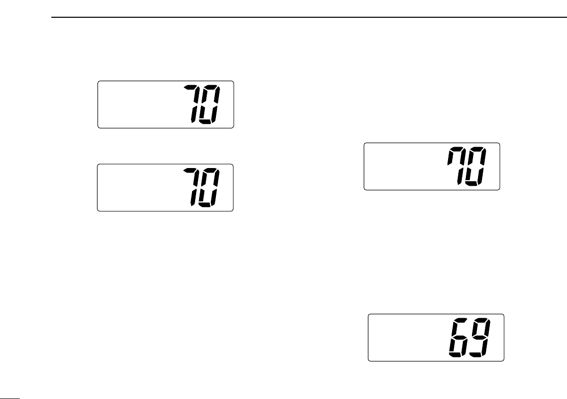
tPush [
[DSC/ENT
DSC/ENT]
]to transmit the Individual call.
• If Channel 70 is busy, the transceiver stands by until the channel
becomes clear.
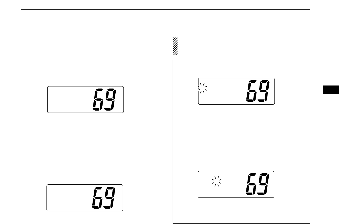
ToCall,
ToCancel
[other]
[DSC/ENT]
Individual
ToCancel
[other]
Ch70isBUSY
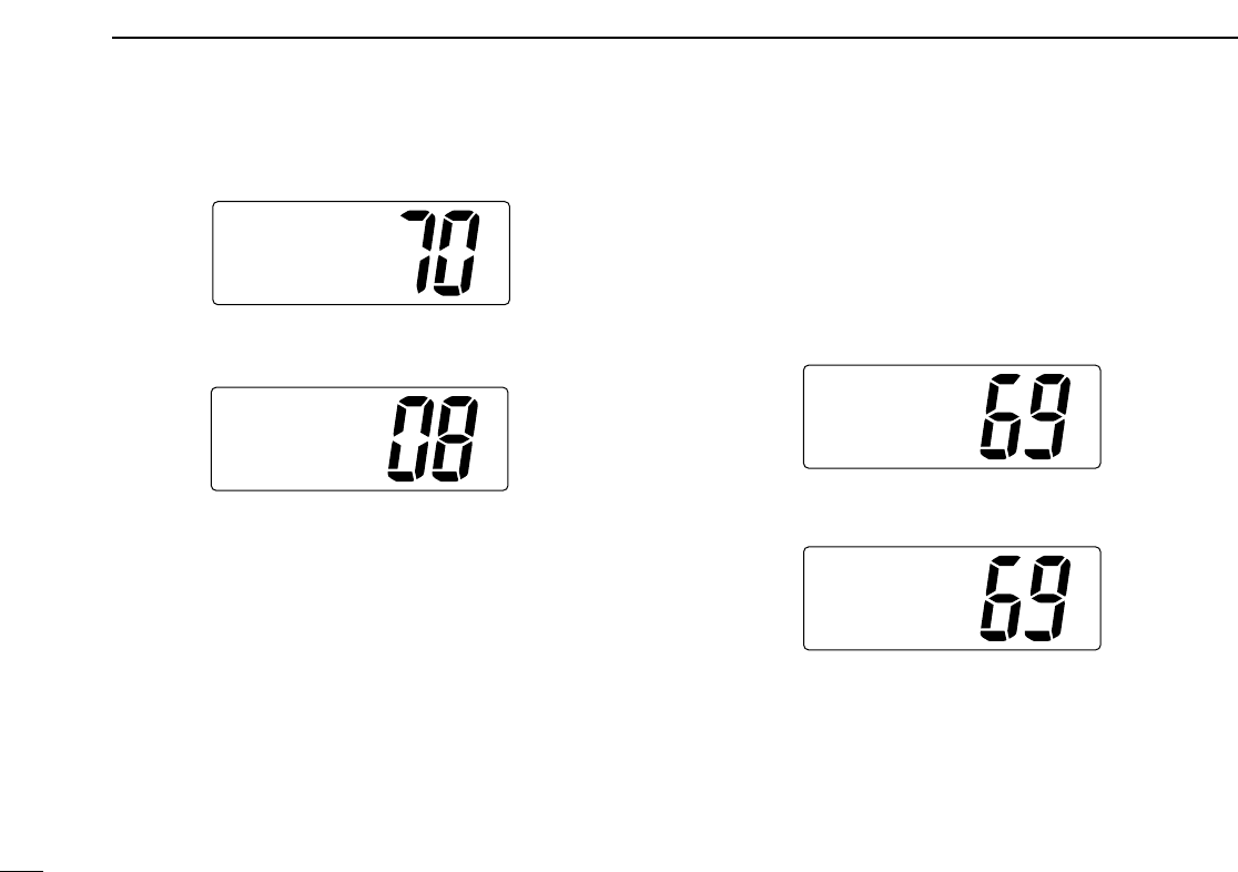
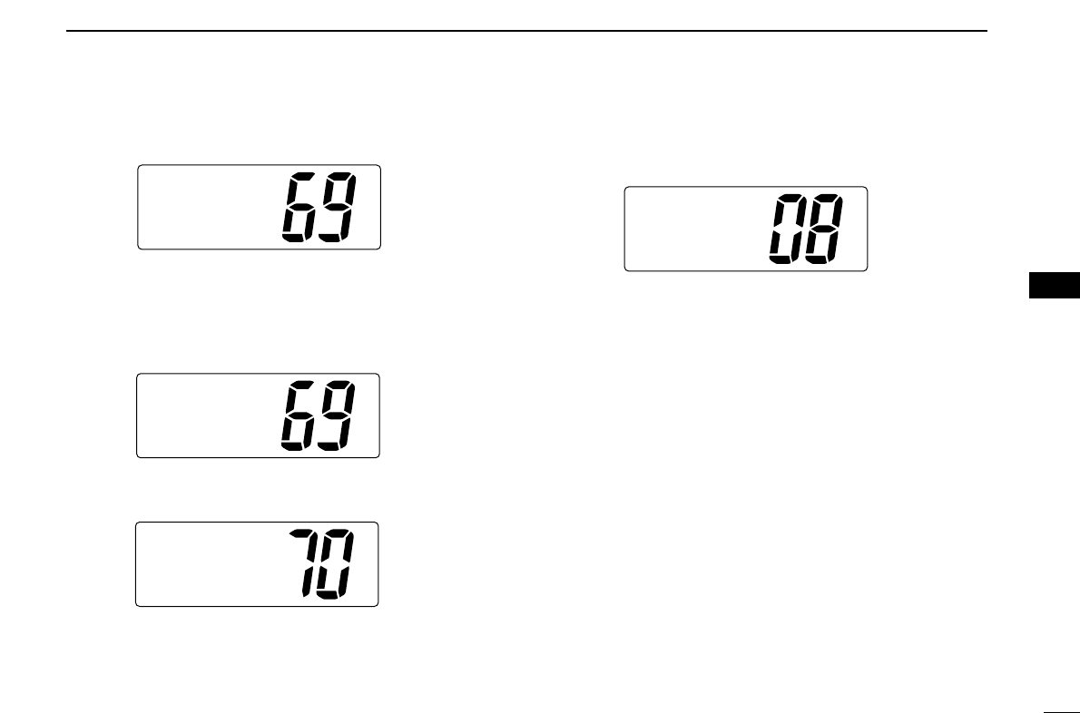
Push [DSC/ENT] to transmit DSC call.
When Ch 70 is busy.
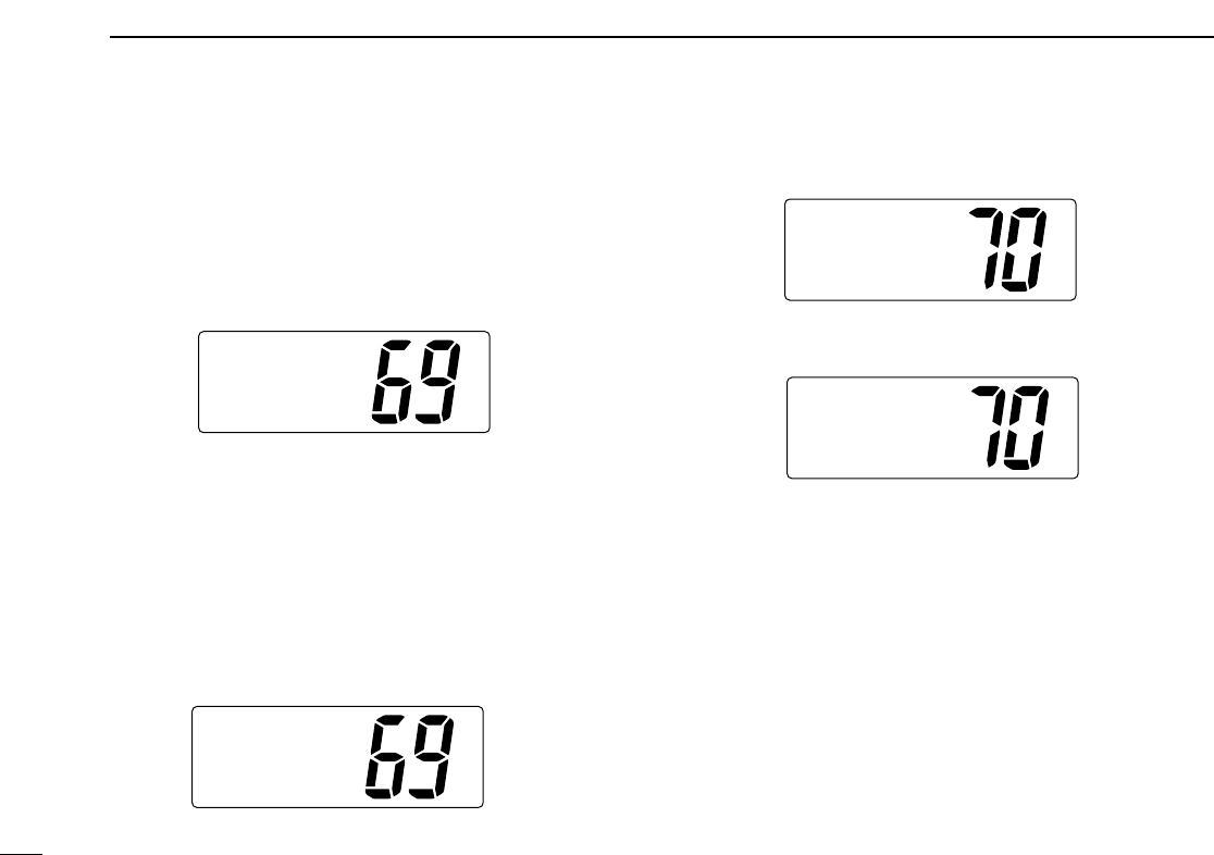
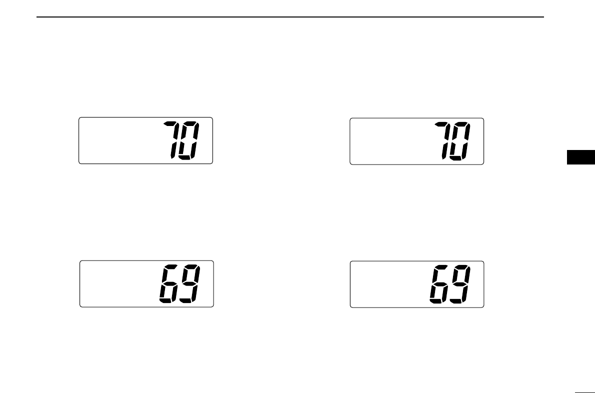
SelChannel
69
˘08
77
SelAddress
Ricky
ManualSet
˘Tom
˘Individual
POSInput
Group
SelItem
22
6DSC OPERATION
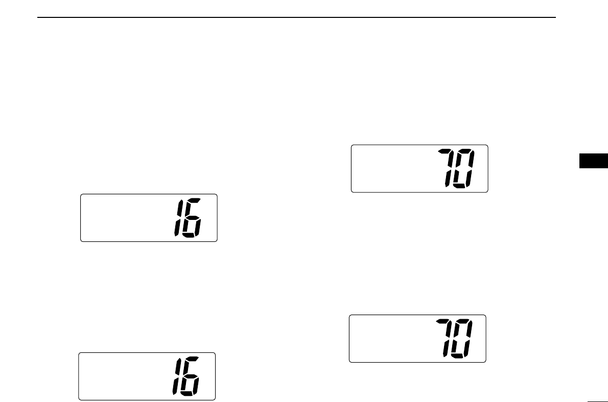
yAfter transmitting the Individual call, standby on Channel
70 until an acknowledgement is received.
uWhen the acknowledgement is received, the display
changes to the previously selected channel with beeps.
iPush and hold [
[PTT
PTT]
]to communicate your message to
the responding ship.
DDTransmitting Individual acknowledgement
Transmit an acknowledgement (‘able to comply’ or ‘unable to
comply’) when an Individual call for you is received.
qPush [
[DSC/ENT
DSC/ENT]
]to enter the DSC menu.
wRotate [
[CHANNEL
CHANNEL]
]to select “INDV ACK,” push
[
[DSC/ENT
DSC/ENT]
].
•“INDV ACK” item appears after an Individual call is received.
eRotate [
[CHANNEL
CHANNEL]
]to select the desired individual ad-
dress or ID code, push [
[DSC/ENT
DSC/ENT]
].
SelAddress
Tom
˘Ricky
SelItem
POS Input
Individual
˘INDVACK
Received
<Tom
AbleACK
Routine
Individual
WaitforACK
Completed
23
6
DSC OPERATION
6
rRotate [
[CHANNEL
CHANNEL]
]to select an acknowledgement
“Able” or “Unable,” push [
[DSC/ENT
DSC/ENT]
].
tIf you select “Unable,” select the reason by rotating
[
[CHANNEL
CHANNEL]
], push [
[DSC/ENT
DSC/ENT]
].
• ‘No reason given,’ ‘Congestion,’ ‘Busy,’ ‘Queue indication,’ ‘Sta-
tion Barred,’ ‘No operator,’ ‘Operator Unavailable,’ ‘Equipment
Disable,’ ‘Channel Unable’ and ‘Mode Unable’ are available.
yPush [
[DSC/ENT
DSC/ENT]
]to transmit the acknowledgement to the
selected station.
uAfter the Individual acknowledgement has been transmit-
ted, the display changes to the channel specified by the
calling station, automatically.
INDVACK
Completed
ToCall,
ToCancel
[other]
[DSC/ENT]
SelReason
Congestion
Busy
˘NoReason
Comply
Unable
˘Able
24
6DSC OPERATION
DDTransmitting Group call
The Group call function allows you to transmit a DSC signal
to a specific group only.
qPush [
[DSC/ENT
DSC/ENT]
]to enter the DSC menu.
wRotate [
[CHANNEL
CHANNEL]
]to select “Group,” push
[
[DSC/ENT
DSC/ENT]
].
eRotate [
[CHANNEL
CHANNEL]
]to select the desired pre-pro-
grammed group address or “Manual Input,” push
[
[DSC/ENT
DSC/ENT]
].
• The ID code for the Group call can be set in advance. (p. 14)
•When “Manual Input” is selected, set the 9-digit ID code
(must be set to ‘0’) for the group you wish to call by using
[
[CHANNEL
CHANNEL]
].
-Push [
[CH/WX
CH/WX]
]or [
[SCAN
SCAN]
]for cursor movement.
- After 9-digit is input, push [
[DSC/ENT
DSC/ENT]
]to set the ID code.
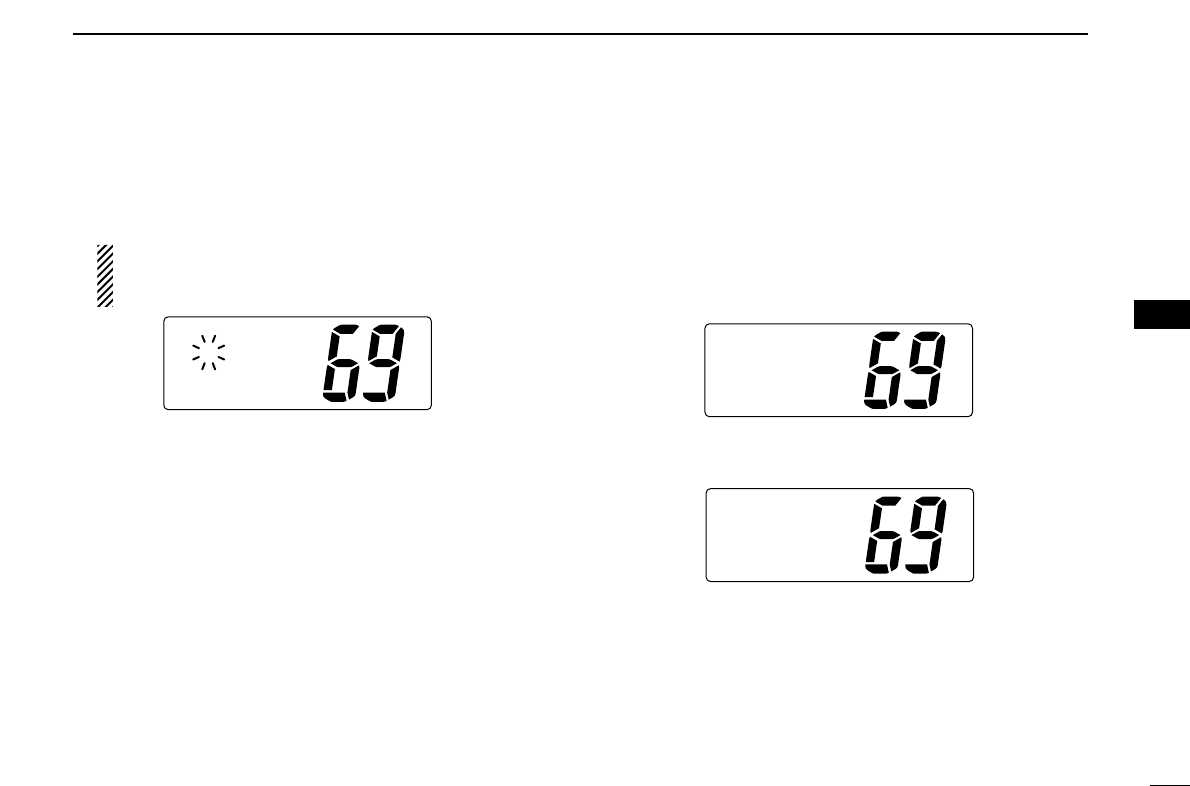
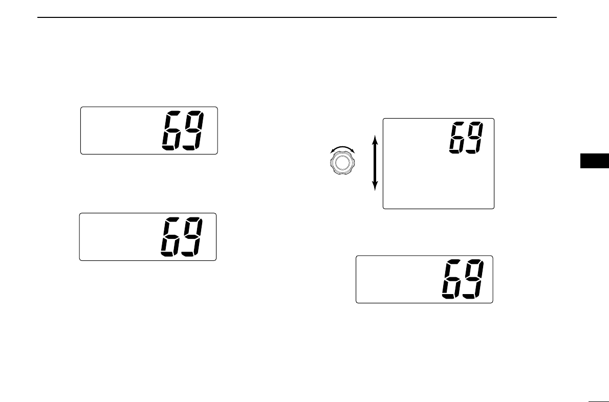
rRotate [
[CHANNEL
CHANNEL]
]to select a desired intership channel
or “Manual Input,” push [
[DSC/ENT
DSC/ENT]
].
• When “Manual Input” is selected, rotate [
[CHANNEL
CHANNEL]
]to se-
lect the desired channel other than Channel 70, push [
[DSC/ENT
DSC/ENT]
].
tPush [
[DSC/ENT
DSC/ENT]
]to transmit the Group call.
• If Channel 70 is busy, the transceiver stands by until the channel
becomes clear.
yAfter the Group call has been transmitted, the display
changes to the previously selected channel.
u
Push and hold [
[PTT
PTT]
]to communicate your message to the
responding ship or push [
[DSC/ENT
DSC/ENT]
]to exit the condition.
Group
Completed
ToCall,
ToCancel
[other]
[DSC/ENT]
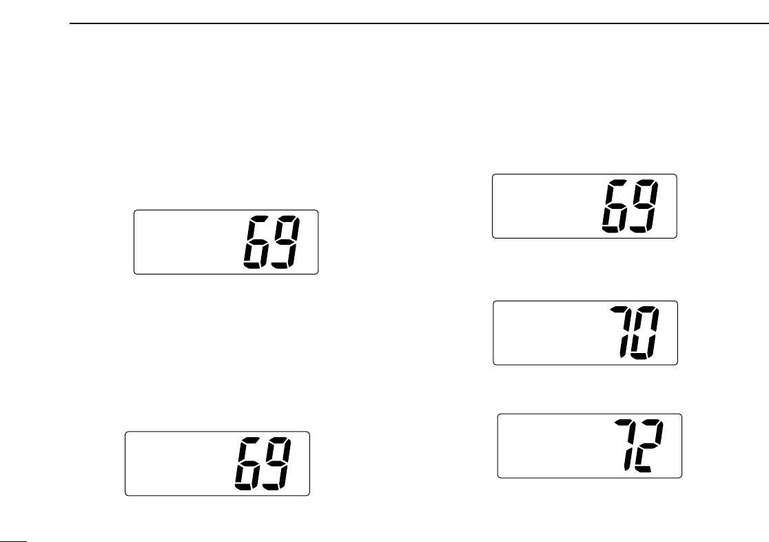
SelChannel
67
13
˘72
SelAddress
Smith Grp
ManualSet
˘Osaka Grp
SelItem
Individual
INDVACK
˘Group
25
6
DSC OPERATION
6
DDTransmitting All Ships call
Large ships use Channel 70 as their ‘listening channel.’ When
you want to announce a message to these ships, use the ‘All
Ships Call’ function.
qPush [
[DSC/ENT
DSC/ENT]
]to enter the DSC menu.
wRotate [
[CHANNEL
CHANNEL]
]to select “All Ships,” push
[
[DSC/ENT
DSC/ENT]
].
ePush [
[DSC/ENT
DSC/ENT]
]to transmit the All Ships call.
• Channel 70 is selected and the All Ships call is transmitted.
• Routine category only is available.
rAfter the All Ships call has been transmitted, the display
changes to Channel 16 automatically.
tPush any key to exit the condition and the display returns
to the normal operation.
AllShips
Completed
ToCall,
ToCancel
[other]
[DSC/ENT]
SelItem
INDVACK
Group
˘AllShips
26
6DSC OPERATION
DDTransmitting Position Request call
Transmit a Position Request call when you want to know a
specific ship’s current position, etc.
qPush [
[DSC/ENT
DSC/ENT]
]to enter the DSC menu.
wRotate [
[CHANNEL
CHANNEL]
]to select “POS Request,” push
[
[DSC/ENT
DSC/ENT]
].
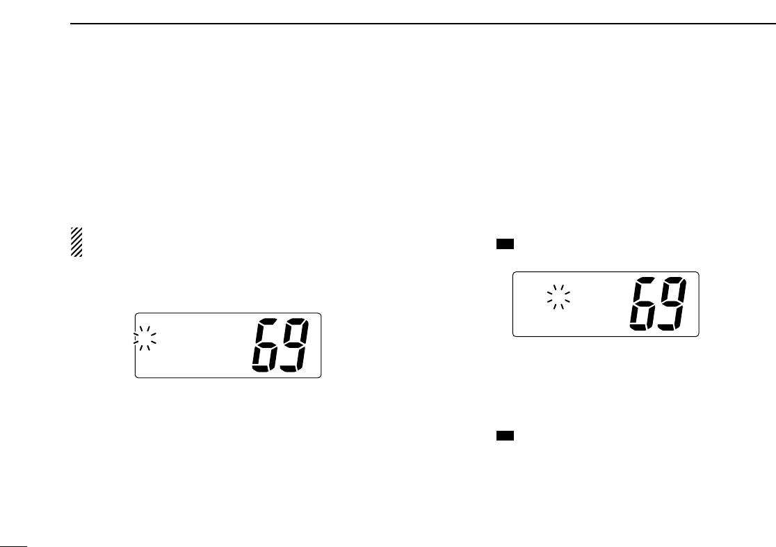
eRotate [
[CHANNEL
CHANNEL]
]to select the desired pre-pro-
grammed individual address or “Manual Input,” push
[
[DSC/ENT
DSC/ENT]
].
• The ID code for the Position Request call can be set in advance.
(p. 14)
•When “Manual Input” is selected, set the 9-digit ID code
(1st digit must not be ‘0’) for the individual you wish to call by
using [
[CHANNEL
CHANNEL]
].
-Push [
[CH/WX
CH/WX]
]or [
[SCAN
SCAN]
]for cursor movement.
- After 9-digit is input, push [
[DSC/ENT
DSC/ENT]
]to set the ID code.
rPush [
[DSC/ENT
DSC/ENT]
]to transmit the Position Request call.
tAfter the Position Request call has been transmitted, the
following indication is displayed.
yPush any key to exit the condition and return to the normal
operation.
POSREQ
WaitforACK
Completed
ToCall,
ToCancel
[other]
[DSC/ENT]
SelAddress
Ricky
ManualSet
˘Tom
SelItem
Group
Allships
˘POSRequest
27
6
DSC OPERATION
6
DDTransmitting Position Report call
Transmit a Position Report call when you want to announce
your own position to a specific ship and to get answer, etc.
qPush [
[DSC/ENT
DSC/ENT]
]to enter the DSC menu.
wRotate [
[CHANNEL
CHANNEL]
]to select “POS Report,” push
[
[DSC/ENT
DSC/ENT]
].
eRotate [
[CHANNEL
CHANNEL]
]to select the desired pre-pro-
grammed individual address or “Manual Input,” push
[
[DSC/ENT
DSC/ENT]
].
• The ID code for the Position Report call can be set in advance.
(p. 14)
•When “Manual Input” is selected, set the 9-digit ID code
(1st digit must not be ‘0’) for the individual you wish to call by
using [
[CHANNEL
CHANNEL]
].
-Push [
[CH/WX
CH/WX]
]or [
[SCAN
SCAN]
]for cursor movement.
- After 9-digit is input, push [
[DSC/ENT
DSC/ENT]
]to set the ID code.
When a GPS receiver (NMEA0183 ver. 2.0 or 3.01) is con-
nected,
next steps r, t(
Current position/time program-
ming) do not appear. Go to step y. (next page)
SelAddress
Ricky
ManualSet
˘Tom
SelItem
Allships
POSRequest
˘POSReport
rThe position information appears. Set the current posi-
tion, push [
[DSC/ENT
DSC/ENT]
].
• Edit the digit of your position data by using [
[CHANNEL
CHANNEL]
].
-Push [
[CH/WX
CH/WX]
]or [
[SCAN
SCAN]
]for cursor movement.
-After editing latitude data, select “N”; North latitude or “S”;
South latitude.
-After editing longitude data, select “E”; East longitude or “W”;
West longitude.
- Push [
[HI/LO
HI/LO]
]to clear the position data.
tThe time information appears. Set the current UTC time,
push [
[DSC/ENT
DSC/ENT]
].
• Edit the digit of the current UTC time by using [
[CHANNEL
CHANNEL]
].
-Push [
[CH/WX
CH/WX]
]or [
[SCAN
SCAN]
]for cursor movement.
- Push [
[HI/LO
HI/LO]
]to clear the time data.
Inputtime
UTC:
Null˘[H/L]
InputPOS
°.
-°.
Null˘[H/L]
28
6DSC OPERATION
yPush [
[DSC/ENT
DSC/ENT]
]to transmit the Position Report call.
uAfter the Position Report call has been transmitted, the fol-
lowing indication is displayed
iPush any key to exit the condition and return to the normal
operation.
DDTransmitting Position Reply call
Transmit a Position Reply call when a Position Request call is
received.
qWhen a Position Request call is received, the following in-
dication is displayed.
wPush [
[DSC/ENT
DSC/ENT]
]to reply to the Position Request call;
push other key to ignore the Position Request call.
DDTransmitting Position Report Reply call
Transmit a Position Report Reply call when a Position Report
call is received.
qWhen a Position Report call is received, the following in-
dication is displayed.
wPush [
[DSC/ENT
DSC/ENT]
]to reply to the Position Report call;
push any key to ignore the Position Report call.
Received
Ans[DSC/ENT]
POSReport
Received
Ans[DSC/ENT]
<Ricky
POSRequest
POSReport
WaitforACK
Completed
ToCall,
ToCancel
[other]
[DSC/ENT]
29
6
DSC OPERATION
6
■Receiving DSC calls
DDReceiving a Distress call
While monitoring Channel 70 and a Distress call is received:
➥The emergency alarm sounds for 2 minutes.
• Push any key to stop the alarm.
➥“Received Distress” appears in the display; then
Channel 16 is automatically selected.
➥Continue monitoring Channel 16 as a coast station may re-
quire assistance.
DDReceiving a Distress acknowledgement
While monitoring Channel 70 and a Distress acknowledge-
ment to other ship is received:
➥The emergency alarm sounds for 2 minutes.
• Push any key to stop the alarm.
➥“Received Distress ACK” appears in the display;
then Channel 16 is automatically selected.
DDReceiving an Individual call
While monitoring Channel 70 and an Individual call is re-
ceived:
➥The emergency alarm or beeps sound depending on the
received category.
➥“Received Individual” appears in the display.
➥Push [
[DSC/ENT
DSC/ENT]
]to change to the channel specified by
the calling station for voice communication; push other key
to ignore the Individual call.
DDReceiving a Group call
While monitoring Channel 70 and a Group call is received:
➥The emergency alarm or beeps sound depending on the
received category.
➥“Received Group” appears in the display.
➥Push [
[DSC/ENT
DSC/ENT]
]to change to the channel specified by
the calling station for voice communication; push other key
to ignore the Group call.
Routine
Group
< Smiths Grp
Received
Routine
Individual
< Tom
Received
<TokyoCG
>111222345
DistressACK
Received
<111222345
Distress
Received
30
6DSC OPERATION
DDReceiving an All Ships call
While monitoring Channel 70 and an All Ships call is received:
➥Emergency alarm sounds when the category is ‘Distress’
or ‘Urgency’; 3 beeps sound for other categories.
➥“Received All ships” appears in the display.
➥Push [
[DSC/ENT
DSC/ENT]
]to change to the channel specified by
the calling station for voice communication; push other key
to ignore the All Ships call.
➥Monitor the channel for an announcement from the calling
vessel.
DDReceiving a Distress Relay call
While monitoring Channel 70 and a Distress Relay call is re-
ceived:
➥Emergency alarm sounds for 2 minutes.
• Push any key to stop the alarm.
➥“Received Distress RLY” appears in the display;
then, Channel 16 is automatically selected.
➥Monitor Channel 16 until the emergency communication
has been completed.
DD
Receiving a Distress Relay acknowledgement
While monitoring Channel 70 and a Distress Relay acknowl-
edgement is received:
➥Emergency alarm sounds for 2 minutes.
• Push any key to stop the alarm.
➥“Received DTRS RLY ACK” appears in the display;
then, Channel 16 is automatically selected.
DDReceiving a Geographical Area call
While monitoring Channel 70 and a Geographical Area call
(for the area you are in) is received:
➥Emergency alarm or beeps sound depending on the re-
ceived category.
➥“Received Geographic” appears in the display.
➥Push [
[DSC/ENT
DSC/ENT]
]to change to the channel specified by
the calling station for voice communication; push other key
to ignore the Geographical Area call.
➥Monitor the selected channel for an announcement from
the calling station.
When no GPS receiver is connected or if there is a prob-
lem with the connected receiver, all Geographical Area
calls are received, regardless of your position.
Routine
Geographic
<TokyoCG
Received
<Osaka Bay
Routine
AllShips
Received
31
6
DSC OPERATION
6
DDReceiving a Position Request call
While monitoring Channel 70 and a Position Request call is
received:
➥“Received POS Request” appears in the display.
➥Push [
[DSC/ENT
DSC/ENT]
]to reply to the Position Request call;
push other key to ignore the Position Request call.
DDReceiving a Position Reply call
While monitoring Channel 70 and a Position Reply call is re-
ceived:
➥“Received POS” appears in the display.
DDReceiving a Position Report call
While monitoring Channel 70 and a Position Report call is re-
ceived:
➥“Received POS Report” appears in the display.
➥Push [
[DSC/ENT
DSC/ENT]
]to reply to the call; push other key to ig-
nore the Position Report call.
DDReceiving a Position Report Reply call
While monitoring Channel 70 and a Position Report Reply call
is received:
➥“Received POS” appears in the display.
30°30.123N
<Ricky
ReceivedPOS
130°30.123E
POSReport
Received
Ans[DSC/ENT]
34°34.123N
<Tom
ReceivedPOS
135°34.123E
<Ricky
POSRequest
Received
Ans[DSC/ENT]
32
6DSC OPERATION
■Received messages
The transceiver automatically stores up to 20 distress mes-
sages and 20 other messages. The messages can be used
as an assistance to the logbook.
qPush [
[DSC/ENT
DSC/ENT]
]to select the DSC menu.
wRotate [
[CHANNEL
CHANNEL]
]to select “RCV Calls,” push
[
[DSC/ENT
DSC/ENT]
].
DDDistress message
qRotate [
[CHANNEL
CHANNEL]
]to select “Distress,” push
[
[DSC/ENT
DSC/ENT]
].
wRotate [
[CHANNEL
CHANNEL]
]to scroll to the desired message,
push [
[DSC/ENT
DSC/ENT]
].
•When some messages are blinking, the messages have not
been read.
eRotate [
[CHANNEL
CHANNEL]
]to scroll the message.
rPush [
[DSC/ENT
DSC/ENT]
]to exit the DSC menu or push [
[HI/LO
HI/LO]
]
to clear the displayed message and returns to the normal
operation.
ToClear
ThisData
No[DSC/ENT]
Yes[H/L]
Distress
<123123123
Explosion
UTC:12:48
32°43.212N
123°45.221W
ToClear
ThisData
No[DSC/ENT]
Yes[H/L]
SelDTRSMSG
˘123123123
111222345
Chuck 3
SelMessege
˘Distress
Other
SelItem
˘RCVCalls
DTRSSet
Setup
33
6
DSC OPERATION
6
DDOther messages
qRotate [
[CHANNEL
CHANNEL]
]to select “Other,” push
[
[DSC/ENT
DSC/ENT]
].
wRotate [
[CHANNEL
CHANNEL]
]to scroll to the desired message,
push [
[DSC/ENT
DSC/ENT]
].
•When some messages are blinking, the messages have not
been read.
eRotate [
[CHANNEL
CHANNEL]
]to scroll the message.
• The stored message has various information and depending on
the type of distress calls.
rPush [
[DSC/ENT
DSC/ENT]
]to exit the DSC menu or push [
[HI/LO
HI/LO]
]
to clear the displayed message and returns to the normal
operation.
ToClear
ThisData
No[DSC/ENT]
Yes[H/L]
AllShips
<Tom
Routine
F3ESimplex
CH08
ToClear
ThisData
No[DSC/ENT]
Yes[H/L]
SelMessege
AllShips
POS Request
˘Individual
SelMessege
Distress
˘Other
34
6DSC OPERATION
■DSC Set mode
DDAdd Address ID (See p.14 for detail)
DDDelete Address ID (See p.15 for detail)
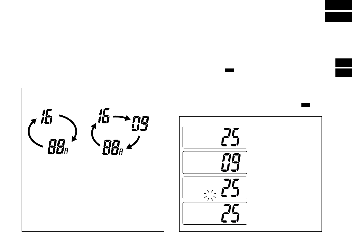
DDOffset time
This item sets the offset time from the UTC (Universal Time
Coordinated) time.
qPush [
[DSC/ENT
DSC/ENT]
]to enter the DSC menu.
wRotate [
[CHANNEL
CHANNEL]
]to select “Set up,” push
[
[DSC/ENT
DSC/ENT]
].
eRotate [
[CHANNEL
CHANNEL]
]to select “Offset time,” push
[
[DSC/ENT
DSC/ENT]
].
rSet the offset time from the UTC (Universal Time Coordi-
nated) time.
• Edit the digit of offset time by using [
[CHANNEL
CHANNEL]
].
-Push [
[CH/WX
CH/WX]
]or [
[SCAN
SCAN]
]for cursor movement.
- Push [
[DSC/ENT
DSC/ENT]
]to set the offset time.
• Rotate [
[CHANNEL
CHANNEL]
]to edit or delete “-,” when the cursor is on
the first digit.
tPush [
[DSC/ENT
DSC/ENT]
]to program and to exit the DSC menu.
The local time indication is not available when a GPS re-
ceiver (sentence formatter ‘RMC’) is input, the trans-
ceiver’s display indicates UTC time only.
OffsetTime
00:00
OffsetTime
-12:00
No offset time (default) —12 hours
Setup
AddID
DeleteID
˘OffsetTime
SelItem
RCVCalls
DTRSSet
˘Setup

35
6
DSC OPERATION
6
DDMMSI code check
The programmed 9-digit MMSI (DSC self ID) code can be
checked in DSC Set mode.
qPush [
[DSC/ENT
DSC/ENT]
]to enter the DSC menu.
wRotate [
[CHANNEL
CHANNEL]
]to select “Set up,” push
[
[DSC/ENT
DSC/ENT]
].
eRotate [
[CHANNEL
CHANNEL]
]to select “MMSI Check,” push
[
[DSC/ENT
DSC/ENT]
].
rCheck the 9-digit MMSI (DSC self ID) code.
tPush [
[DSC/ENT
DSC/ENT]
]to exit the DSC menu.
MMSI Check
123456789
Setup
DeleteID
OffsetTime
˘MMSICheck
SelItem
RCVCalls
DTRSSet
˘Setup
36
7OTHER FUNCTIONS
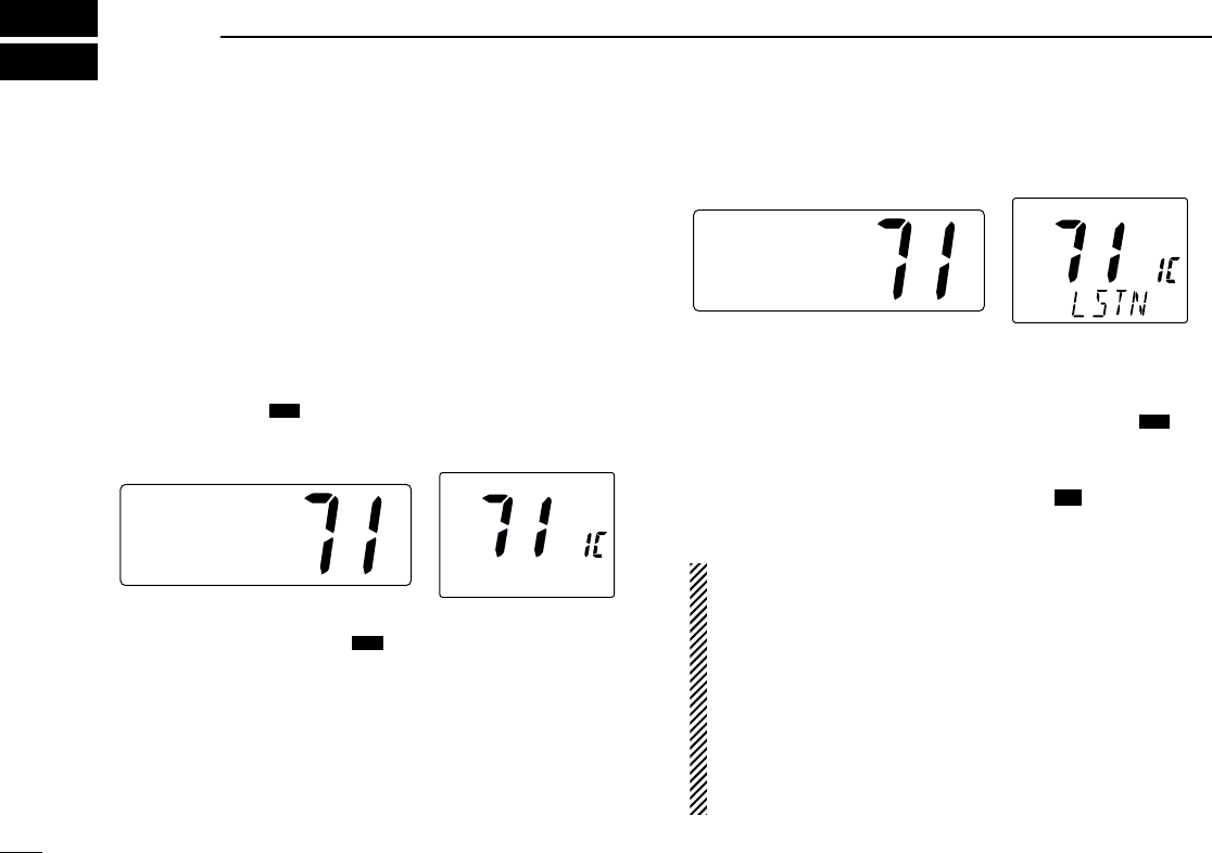
■Intercom operation
The optional Intercom function allows you to talk to the deck
from the cabin. The optional HM-127 REMOTE-CONTROL MI-
CROPHONE is required for Intercom operation.
Connect an optional HM-127 as described on pgs. 43, 65.
• Transmitting is impossible during Intercom operation.
• The received signal is muted during Intercom operation.
qPush [
[LO/DX
LO/DX]
](
(SCR)
SCR) for 1 sec. to enter Intercom mode.
• The HM-127 power is automatically turned ON, even if the power
is OFF.
wPush and hold [
[LO/DX
LO/DX]
](
(SCR)
SCR) again to call up.
• The transceiver and microphone emit call beeps.
ePush and hold the PTT switch and speak at a normal voice
level into the microphone.
•“TALK” or “LSTN” appears on the caller or listener function dis-
play, respectively.
• To adjust the IC-M502A’s speaker output level, rotate [
[VOL
VOL]
].
• To adjust the HM-127’s speaker output level, push after [
[VOL
VOL]
]
pushing [
[YY
YY]
]/[
[ZZ
ZZ]
].
rAfter releasing the PTT switch you can hear the response
through the speaker.
tTo return to the normal operation, push [
[LO/DX
LO/DX]
](
(SCR)
SCR)
momentarily.
• Other keys also turn the function OFF, however, the correspond-
ing function is then activated (e.g. pushing [
[9
9]
]selects Chan-
nel 16).
•While in the Intercom mode, the transceiver functions
(transmit and receive) are interrupted. If the transceiver is
in transmit condition, the Intercom function is not avail-
able.
•When a DSC call is received, “DSC received” ap-
pears and the last received DSC message is displayed
after the Intercom use is finished.
•When a WX alert is received, “WX ALT” blinks and a
beep sounds. The WX alert sounds after the Intercom use
is finished.
16
16
IC
Intercom
INT
INT
TALK
IC-M502A (caller) HM-127 (listener)
IC
Intercom
INT
INT
IC-M502A HM-127
IC

37
7
OTHER FUNCTIONS
7
■Microphone lock function
The Microphone lock function electrically locks the [
[YY
YY]
]/[
[ZZ
ZZ]
]
and [
[16/9
16/9]
]keys on the supplied microphone. This prevents
accidental channel changes and accidental function access.
➥While pushing [
[16/9
16/9]
]on supplied microphone, turn power
ON to toggle the Lock function ON or OFF.
■Display backlighting
The function display and keys can be backlit for better visibil-
ity under low light conditions.
➥While pushing [
[HI/LO
HI/LO]
], rotate [
[CHANNEL
CHANNEL]
]to adjust the
brightness of the LCD and key backlight.
• The backlight level is adjustable in 7 levels.
• No backlight level indication is available.
[Y]/[Z][16/9]
8SET MODE
38
Beep tone
Beep
Scan mode
Scan Mode
Weather alert
WX Alert
Scan resume timer
Scan Timer
Attenuation level
Attenuation
Level
Internal speaker
Internal
Speaker
Scrambler code*
Scrambler
Code
Scrambler type*
Scrambler
Type
Dual/tri watch
DUAL/TRI
DSC watch
DSCWatch
LCD contrast
LCD
Contrast
Automatic acknowledgement
AUTO ACK
Push 916
* The scrambler set items
are only available when a
scrambler unit is installed.
Push when using HM-127
DSC Watch, Internal Speaker
and AUTO ACK items are not selectable
when using HM-127.
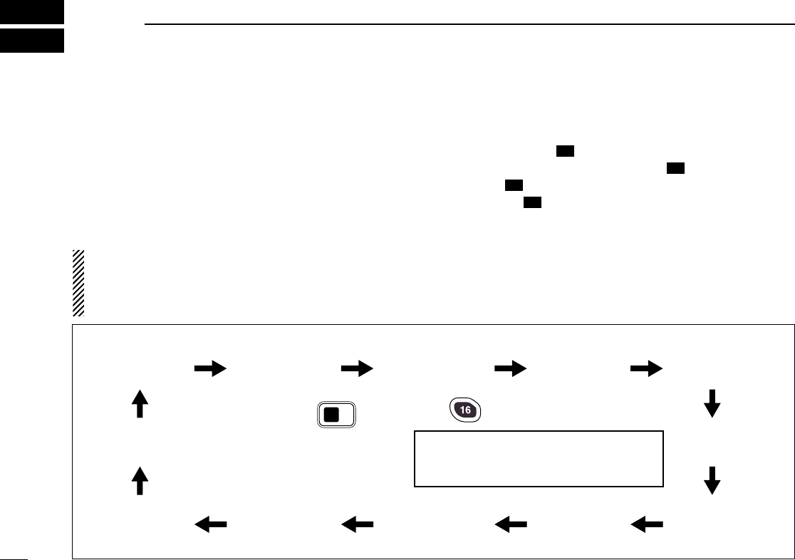
■Set mode programming
Set mode is used to change the conditions of the trans-
ceiver’s functions: scan mode (Normal or Priority), scan re-
sume timer, weather alert, Dualwatch/Tri-watch selection,
DSC watch, transceiver’s beep tone (transceiver or HM-127),
internal speaker, LCD contrast (transceiver or HM-127), RF
attenuation level, scrambler code, scrambler type and auto-
matic acknowledgement.
•Available functions may differ depending on dealer set-
ting.
•The optional HM-127 has it’s own settings for the beep
tone and LCD contrast.
qTurn power OFF.
wWhile pushing [
[9
9]
], turn power ON to enter Set mode.
eAfter the display appears, release [
[9
9]
].
rPush [
[9
9]
]to select the desired item.
Or push [
[]
](
(9
9)
)on the HM-127 to select the item when
using an optional HM-127.
tRotate [
[CHANNEL
CHANNEL]
]to select the desired condition of the
item. Use [
[YY
YY]
]/[
[ZZ
ZZ]
]when using an optional HM-127.
yTurn power OFF, then turn ON again to exit Set mode.
16
16
16
16
16
16
16
16
•SET MODE CONSTRUCTION
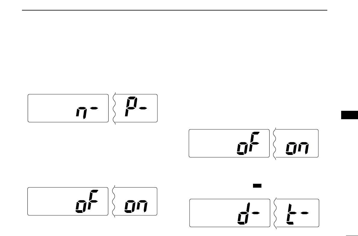
8
SET MODE
39
■Set mode items
DDScan mode
The transceiver has 2 scan modes: Normal scan and Priority
scan. Normal scan searches all tag channels in the selected
channel group. Priority scan searches all tag channels in se-
quence while monitoring Channel 16.
DDScan resume timer
The scan resume timer can be selected as a pause (OFF) or
timer scan (ON). When OFF is selected, the scan pauses
until the signal disappears. When ON is selected, the scan
pauses 5 sec. and resumes even if a signal has been re-
ceived on any other channel than Channel 16.
DDWeather alert
A NOAA broadcast station transmits a Weather alert tone be-
fore important weather information. When the Weather alert
function is turned ON, the transceiver detects the alert tone,
then blinks the “WX ALT” indicator and sounds beep tones
until the transceiver is operated. The previously selected
(used) weather channel is checked any time during standby
or while scanning.
•“WX ALT” appears instead of “WEATHER” indication when the
function is set ON.
DDDual/Tri-watch
This item sets the [
[CH/WX
CH/WX]
](
(U/I/C)
U/I/C) key function as Dual-
watch or Tri-watch.
SetMode
DUAL/TRI
Dualwatch (default) Tri-watch
DW
SetMode
WXAlert
Weather alert OFF (default) Weather alert ON
SetMode
ScanTimer
Scan timer OFF (default) Scan timer ON
SetMode
ScanMode
Normal scan (default) Priority scan
8
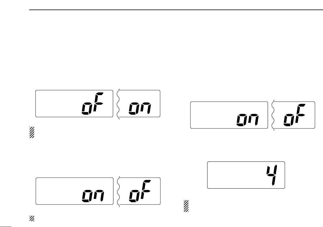
40
8SET MODE
DDDSC watch
DSC watch monitors Channel 70 while you are receiving an-
other channel.
If a distress signal is received on Channel 70, the transceiver
monitors Channel 16 and 70 alternately until the distress sig-
nal disappears. If a signal is received on another channel,
DSC watch pauses until the signal disappears.
This function may not be available for some channel
groups depending on dealer setting.
DDBeep tone
You can select silent operation by turning beep tones OFF, or
you can have confirmation beeps sound at the push of a key
by turning beep tones ON.
The optional HM-127 has its own setting for the beep tone.
DDInternal speaker
When an external speaker is connected and the transceiver’s
internal speaker is not required, the speaker on the trans-
ceiver and microphone can be deactivated.
“SP OFF” appears on the function display when the internal
speaker is turned OFF.
•The order of indication precedence is “SP OFF,” “LOCAL” and
“CALL.”
DDLCD contrast
This item adjusts the contrast of the LCD in 8 steps.
The optional HM-127 has its own setting for the LCD con-
trast.
SetMode
LCD
Contrast
LCD contrast 4 (default)
SetMode
Internal
Speaker
Internal speaker ON (default) Internal speaker OFF
SetMode
Beep
Beep tone ON (default) Beep tone OFF
SetMode
DSCwatch
DSC watch OFF (default) DSC watch ON
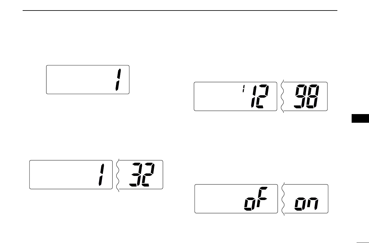
41
8
SET MODE
DDAttenuation level
This item sets the receive attenuation level for the Attenuator
function from 3 levels.
DDScrambler code
(Appears when a scrambler unit is installed)
When an optional scrambler unit is installed, the scrambler
code can be set depending on dealer setting.
When the UT-98 or UT-112 is installed, 128 or 32 codes (0 to
127 or 1 to 32) can be selected.
DDScrambler type
(Appears when a scrambler unit is installed)
When an optional scrambler unit is installed, the scrambler
type can be selected in Set mode depending on dealer set-
ting.
DDAutomatic acknowledgement
This item sets the Automatic acknowledgement function ON
or OFF.
When Position Request or Position Report call is received,
transceiver automatically transmits Position Reply or Position
Report Reply, respectively.
SetMode
AUTOACK
Auto ACK OFF (default) Auto ACK ON
SetMode
Scrambler
Type
UT-112 scrambler unit UT-98 scrambler unit
SetMode
Scrambler
Code
Scrambler code 1 (UT-112 default) Scrambler code 32
SetMode
Attenuation
Level
Attenuation level 1 (default)
8
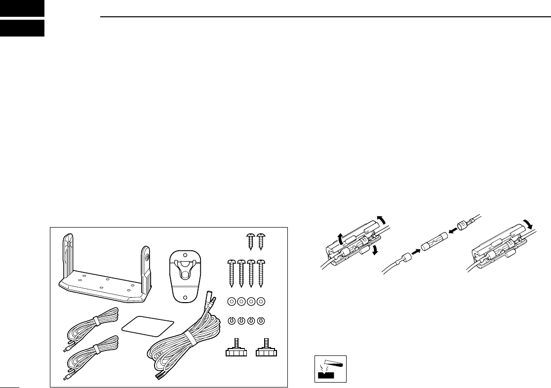
■Supplied accessories
The following accessories are supplied: Qty.
qMounting bracket ............................................................ 1
wMicrophone hanger ......................................................... 1
eMic hanger screws (3 ×16) ............................................ 2
rMounting screws (5 ×20) ............................................... 4
tFlat washers (M5) ........................................................... 4
ySpring washers (M5) ...................................................... 4
uKnob bolts for mounting bracket...................................... 2
iDC power cable (OPC-891) ........................................... 1
oWarning sticker ............................................................... 1
!0 RCA connector cable Red (OPC-1278) .......................... 1
!1 RCA connector cable White (OPC-1279) ....................... 1
■Antenna
A key element in the performance of any communication sys-
tem is an antenna. Ask your dealer about antennas and the
best place to mount them.
■Fuse replacement
One fuse is installed in the supplied DC power cable. If a fuse
blows or the transceiver stops functioning, track down the
source of the problem, if possible, and replace the damaged
fuse with a new, rated one.
■Cleaning
If the transceiver becomes dusty or dirty, wipe it clean with a
soft, dry cloth.
AVOID the use of solvents such as benzene or al-
cohol, as they may damage transceiver surfaces.
Fuse rating: 10 A
qw e
r
t
y
ui
WARNING
o!0
!1
42
9CONNECTIONS AND MAINTENANCE
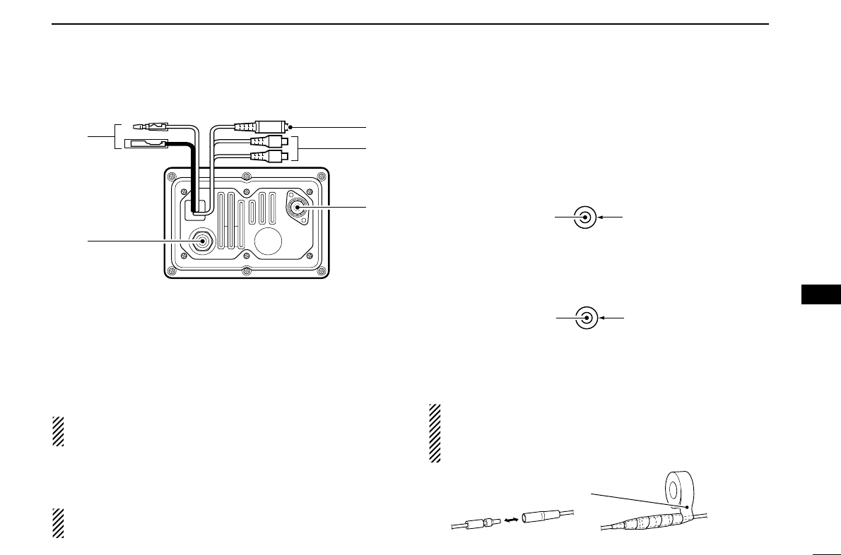
43
9
CONNECTIONS AND MAINTENANCE
■Connections
qDC POWER CONNECTOR
Connects the supplied DC power cable from this connector
to an external 13.8 V DC power source.
wEXTERNAL MICROPHONE JACKS
Connects to optional HM-127 REMOTE-CONTROL MICRO-
PHONE.
CAUTION: NEVER
connect other microphones, such
as the HM-134, as this may cause damage to the transceiver.
eANTENNA CONNECTOR
Connects a marine VHF antenna with a PL-259 connector.
CAUTION: Transmitting without an antenna may dam-
age the transceiver.
rNMEA IN (Red)/NMEA OUT (White) JACKS
Connects to a GPS receiver for position and time indica-
tions.
•An NMEA0183 ver. 2.0 or 3.01 (sentence formatters RMC,
GGA, GNS, GLL) compatible GPS receiver is required. Ask your
dealer about suitable GPS receivers.
Connects to a PC or navigation equipment (NMEA0183
ver. 3.01 sentence formatters DSC, DSE compatible) for
plotting received other ships position data.
tEXTERNAL SPEAKER JACK
➥Connects to an external speaker.
CAUTION: After connecting the DC power cable, NMEA
IN/OUT jacks and external speaker jack cover the connec-
tor and jacks with a rubber vulcanising tape as shown
below, to prevent water seeping into the transceiver.
Rubber vulcanizing
tape
NMEA OUT (+)
RCA
NMEA OUT (–)
NMEA IN (+)
RCA
NMEA IN (–)
q
w
e
t
r
9
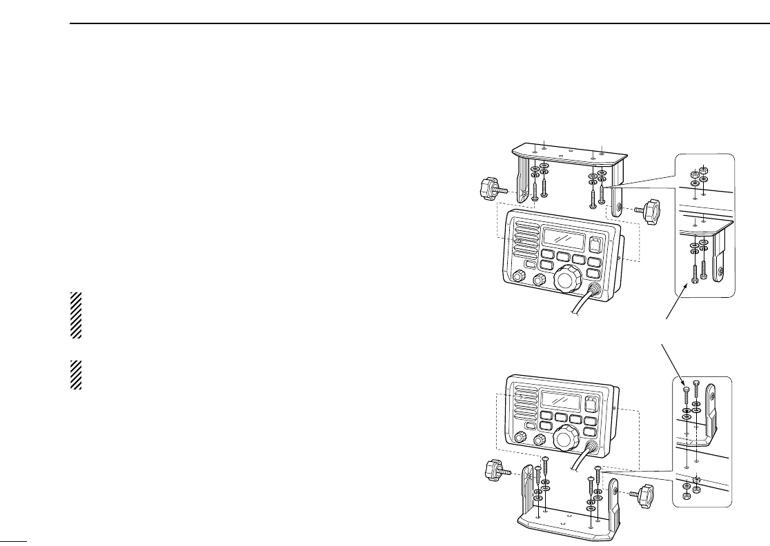
44
9CONNECTIONS AND MAINTENANCE
■Mounting the transceiver
DDUsing the supplied mounting bracket
The universal mounting bracket supplied with your transceiver
allows overhead or onboard mounting.
•Mount the transceiver securely with the 4 supplied screws
(M5 ×20) to a surface which is more than 10 mm thick and
can support more than 5 kg.
• Mount the transceiver so that the face of the transceiver is at
90° to your line of sight when operating it.
CAUTION: KEEP the transceiver and microphone at
least 1 meter away from your vessel’s magnetic navigation
compass.
NOTE: Check the installation angle; the function display
may not be easy-to-read at some angles.
These screws are shown as mounting example only.
Not supplied with accessories.
• OVERHEAD MOUNTING
• MOUNTING ON THE BOARD
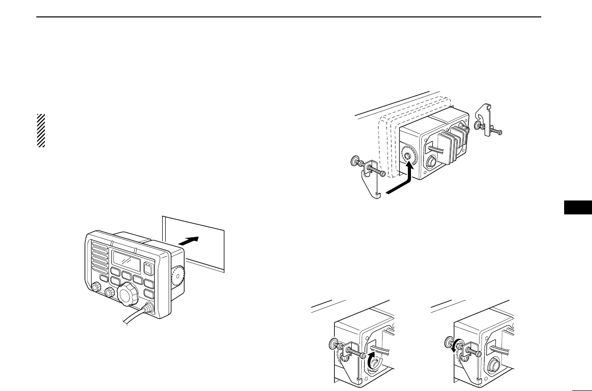
45
9
CONNECTIONS AND MAINTENANCE
DDUsing the optional MB-75
An optional MB-75 FLUSH MOUNT is available for mounting
the transceiver to a flat surface such as an instrument panel.
CAUTION: KEEP the transceiver and microphone at
least 1 meter away from your vessel’s magnetic navigation
compass.
qUsing the template on the last page, carefully cut a hole
into the instrument panel (or wherever you plan to mount
the transceiver).
wSlide the transceiver through the hole as shown below.
eAttach the 2 supplied bolts (M5 ×8 mm) on either side of
the IC-M502A.
rAttach the clamps on either side of the IC-M502A.
• Make sure that the clamps align parallel to the IC-M502A’s body.
tTighten the end bolts on the clamps (rotate clockwise) so
that the clamps press firmly against the inside of the in-
strument control panel.
yTighten the locking nuts (rotate counterclockwise) so that
the IC-M502A is securely mounted in position as below.
uConnect the antenna and power cable, then return the in-
strument control panel to its original place.
9
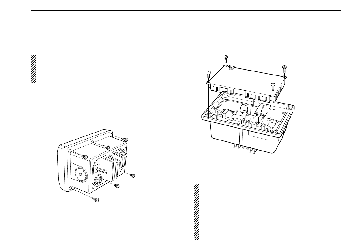
46
9CONNECTIONS AND MAINTENANCE
■Optional unit installation
CAUTION: DISCONNECT the DC power cable from the
transceiver before performing any work on the transceiver.
Otherwise, there is danger of electric shock and/or equip-
ment damage.
Follow the case opening procedure shown here when you
want to install an optional unit.
qRemove the 6 screws as shown below and open the trans-
ceiver.
wRemove the 4 screws from the shielding plate, then lift up
the shielding plate.
ePlug an optional unit (UT-98 or UT-112) to J3 on the MAIN
unit as shown below.
rReturn the shielding plate and assemble the units to their
original positions.
CAUTION:
• When re-assembling the case and tightening the screws,
you must keep the specified torque (0.7±0.1 N.m). Oth-
erwise the transceiver may be damaged (torque too high)
or lose waterproof efficiency (torque too low).
• When uninstalling the optional unit, remove it vertically.
Wiggling the unit from side to side may damage the op-
tional unit's connector.
Optional unit
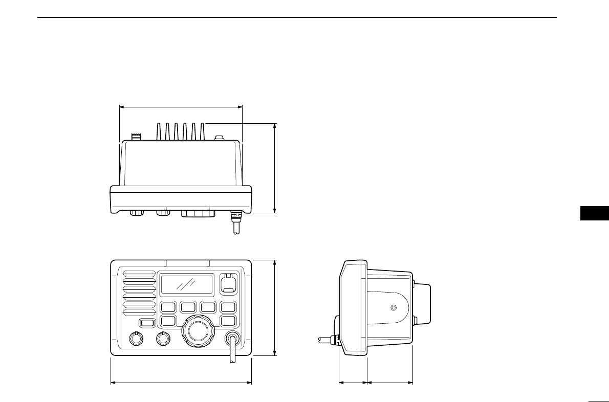
47
9
CONNECTIONS AND MAINTENANCE
■Dimensions
145.0 (5 23⁄32)
165.0 (6 1⁄2)
31.4
(1 1⁄4)
53.0
(2 3⁄32)Unit: mm (inch)
110.0 (4 11⁄32) 109.4 (4 5⁄16)
9

10 TROUBLESHOOTING
48
PROBLEM POSSIBLE CAUSE SOLUTION REF.
No power comes ON. •Bad connection to the power supply. •Check the connection to the transceiver. p. 43
No sound comes from
the speaker.
•Squelch level is too high.
•Volume level is too low.
•Speaker has been exposed to water.
•Internal speaker is turned OFF.
•Set squelch to the threshold point.
•Set [VOL] to a suitable level.
•Drain water from the speaker.
•Turn the internal speaker ON in Set mode.
p. 8
p. 8
—
p. 40
Transmitting is impossi-
ble, or high power can
er can
-
not be selected.
•Some channels are for low power or re-
ceive only.
•The output power is set to low.
•Change channels.
•Push [HI/LO] to select high power.
pgs.
6, 49
p. 8
Scan does not start. •‘TAG’ channel is not prog rammed. •Set the desired channels as ‘TAG’ chan-
nels.
p. 13
No beep sounds. •Beep tone is turned OFF.
•The squelch is open.
•Turn the beep tone ON in Set mode.
•Set squelch to the threshold point.
p. 40
p. 8
Receive signal cannot
be understood.
•Optional voice scrambler is turned OFF.
•Scramble code is not set correctly.
•Turn the optional voice scrambler ON.
•Reset the scramble code.
p. 10
p. 41
Sensitivity is low. •The attenuator is activated. •Push [LO/DX] to turn the function OFF. p. 8
Distress call cannot be
transmitted.
•MMSI (DSC self ID) code is not pro-
grammed.
•Program the MMSI (DSC self ID) code. p. 14
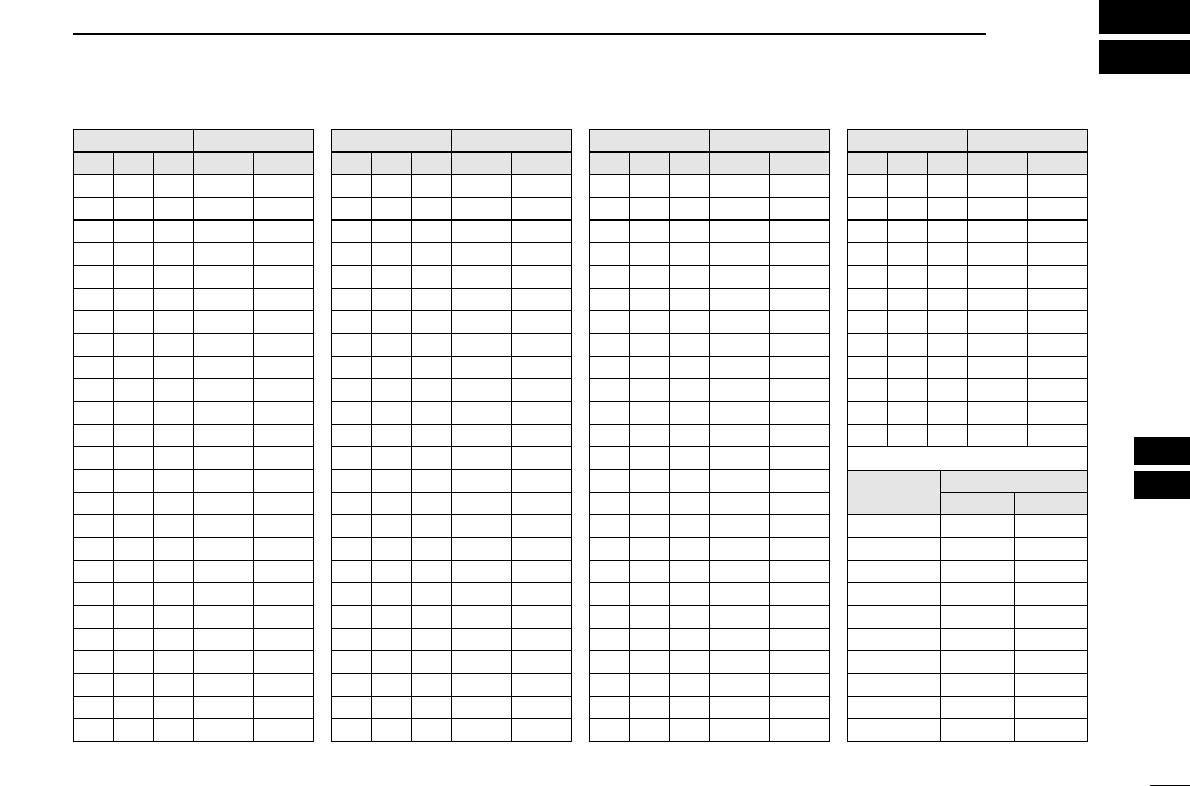
11
CHANNEL LIST
49
Channel number
USA CAN
Transmit
Receive
01 156.050 160.650
01A 156.050 156.050
02 156.100 160.700
03 156.150 160.750
03A 156.150 156.150
156.200 160.800
04A 156.200 156.200
156.250 160.850
05A 05A 156.250 156.250
06 06 156.300 156.300
156.350 160.950
07A 07A 156.350 156.350
08 08 156.400 156.400
09 09 156.450 156.450
10 10 156.500 156.500
11 11 156.550 156.550
12 12 156.600 156.600
13†13†156.650 156.650
14 14 156.700 156.700
15†15†156.750 156.750
16 16 156.800 156.800
17†17†156.850 156.850
156.900 161.500
18A 18A 156.900 156.900
Frequency (MHz)
INT
01
02
03
04
05
06
07
08
09
10
11
12
13
14
15†
16
17
18
Channel number Frequency (MHz)
USA CAN
Transmit
Receive
19A 19A 156.950 156.950
20 20†157.000 161.600
21 157.050 161.650
21A 21A 157.050 157.050
157.100 161.700
22A 22A 157.100 157.100
23 157.150 161.750
23A 157.150 157.150
24 24 157.200 161.800
25 25 157.250 161.850
26 26 157.300 161.900
27 27 157.350 161.950
28 28 157.400 162.000
60 156.025 160.625
156.075 160.675
61A 61A 156.075 156.075
156.125 160.725
62A 156.125 156.125
156.175 160.775
63A 156.175 156.175
64 156.225 160.825
INT
20
21
22
23
24
25
26
27
28
60
61
62
63
64
20A 157.000 157.000
Channel number
66A
Frequency (MHz)
66A†
USA CAN
Transmit
Receive
64A 64A 156.225 156.225
65A 65A 156.275 156.275
156.325 160.925
67†67 156.375 156.375
68 68 156.425 156.425
69 69 156.475 156.475
70‡70‡156.525 156.525
71 71 156.575 156.575
72 72 156.625 156.625
73 73 156.675 156.675
74 74 156.725 156.725
77†77†156.875 156.875
156.925 161.525
78A 78A 156.925 156.925
156.975 161.575
79A 79A 156.975 156.975
157.025 161.625
80A 80A 157.025 157.025
157.075 161.675
81A 81A 157.075 157.075
157.125 161.725
82A 82A 157.125 157.125
INT
65A
66
67
68
69
70‡
71
72
73
74
77
78
79
80
81
82
156.325 156.32566A
Channel number
84A
Frequency (MHz)
USA CAN
Transmit
Receive
83A 83A 157.175 157.175
84 84 157.225 161.825
85 85 157.275 161.875
85A 157.275 157.275
86 86 157.325 161.925
86A 157.325 157.325
87 87 157.375 161.975
87A 157.375 157.375
88 88 157.425 162.025
88A 157.425 157.425
INT
84
85
86
87
88
157.225 157.225
WX channel
4
Frequency (MHz)
Transmit Receive
1 RX only 162.550
2 RX only 162.400
3 RX only 162.475
5 RX only 162.450
6 RX only 162.500
7 RX only 162.525
8 RX only 161.650
9 RX only 161.775
10 RX only 163.275
RX only 162.425
†Low power only. ‡DSC operation only.
156.950 161.55019
21b Rx only 161.650
25b Rx only 161.850
156.275 160.87565
28b Rx only 162.000
83 157.175 161.77583
83b Rx only 161.775
NOTE: Simplex channels, 3, 21, 23, 61, 64, 81, 82 and 83 CANNOT
be lawfully used by the general public in U.S.A. waters.
10
11

50
12 SPECIFICATIONS AND OPTIONS
■Specifications
DDGeneral
• Frequency coverage :
Transmit 156.025–157.425 MHz
Receive 156.050–163.275 MHz
• Mode : FM (16K0G3E)
DSC (16K0G2B)
• Channel spacing : 25 kHz
• Current drain (at 13.8 V) : TX high 5.5 A max.
Max. audio 1.5 A max.
• Power supply requirement: 13.8 V DC ±15%
• Frequency stability : ±10 ppm
(–20°C to +60°C; –4°F to +140°F)
• Dimensions : 165(W) ×110(H) ×109.4(D) mm
(Projection not included) 6 1⁄2(W) ×411⁄32(H) ×45⁄16(D) in
• Weight (approx.) : 1130 g; 2 lb 8 oz
DDTransmitter
• Output power : 25 W / 1 W
• Modulation system : Variable reactance phase
modulation
• Max. frequency deviation : ±5.0 kHz
• Spurious emissions : –70 dBc
DDReceiver
• Receive system :
Double conversion
superheterodyne
• Sensitivity (12 dB SINAD) : 0.22 µV (typical)
• Squelch sensitivity : 0.22 µV (typical)
•
Intermodulation rejection ratio
: More than 75 dB
• Spurious response : More than 75 dB
rejection ratio
•
Adjacent channel selectivity
: More than 75 dB
• Audio output power : 4.5 W (typical) at 10% distortion
with a 4 Ωload
All stated specifications are subject to change without
notice or obligation.

51
12
SPECIFICATIONS AND OPTIONS
■Options
•MB-75 FLUSH MOUNT
For mounting the transceiver to a panel.
•SP-5 EXTERNAL SPEAKER
A large, external speaker for superior audio output.
•SP-10 EXTERNAL SPEAKER
A compact, external speaker. Features easy installation.
•UT-98/ UT-112 VOICE SCRAMBLER UNIT (pgs. 10, 41)
Ensures private communications. 128 (for UT-98) or 32 (for
UT-112) codes are available. Not available in some countries.
•HM-127 REMOTE-CONTROL MICROPHONE (p. 52)
External microphone-type controller. Provides optional Inter-
com operation. 6 m (20 feet) microphone cable and mount-
ing base included. Black and white colors are available.
•OPC-999 MICROPHONE EXTENSION CABLE
6 m (20 feet) microphone extension cable for optional
HM-127. Up to 2 OPC-999 can be connected. (18 m; 60 feet
maximum)
12
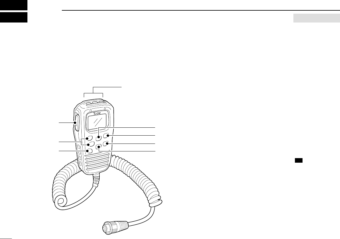
52
13 HM-127 REMOTE-CONTROL MICROPHONE OPTION
■Panel description
The optional HM-127 remotely controls the IC-M502A and
provides an optional Intercom function.
DDFront and side keys
qPTT SWITCH [
[PTT
PTT]
](pgs. 8, 57)
Push and hold to transmit; release to receive.
wCHANNEL UP/DOWN KEYS [
[YY
YY]
]/[
[ZZ
ZZ]
]
➥Push either key to change the operating channel, Set
mode settings, etc. (pgs. 8, 57)
➥Push either key to adjust audio level or noise squelch
level after [
[VOL
VOL]
]or [
[SQL
SQL]
]is pushed, respectively.
(pgs. 8, 57)
➥
Push either key to adjust the brightness of the LCD and
key backlight after [
[VOL
VOL]
]is pushed for 1 sec. (p. 58)
➥In Set mode, changes setting of the selected item. (pgs.
38, 62)
➥Checks tag channels or changes scanning direction dur-
ing scan. (pgs. 13, 61)
eCHANNEL 16/CALL CHANNEL KEY [
[]
](
(9
9)
)
➥Selects Channel 16 when pushed. (pgs. 6, 56)
➥Selects call channel when pushed for 1 sec. (pgs. 6, 56)
•“CALL” appears when call channel is selected.
➥Push for 3 sec. to enter call channel programming con-
dition when call channel is selected. (pgs. 9, 59)
➥While pushing [
[H/L
H/L]
], enters channel comments pro-
gramming condition. (pgs. 9, 63)
➥Enters Set mode when pushed while turning power ON.
(pgs. 38, 62)
16
16
Top keys
q
e
w
y
t
r
u

53
13
HM-127 REMOTE-CONTROL MICROPHONE
rCHANNEL/DUALWATCH/TRI-WATCH KEY
[
[CH/WX
CH/WX]
](
(U/I/C)
U/I/C)
➥Selects and toggles the regular channels and weather
channel when pushed momentarily. (pgs. 6, 7, 56)
➥While pushing [
[H/L
H/L]
], selects one of 3 regular channels
in sequence when pushed. (pgs. 7, 56)
•International, U.S.A. and Canadian channels are available for
regular channels.
➥Starts Dualwatch or Tri-watch when pushed for 1 sec.
(pgs. 11, 60)
➥Stops Dualwatch or Tri-watch when either is activated.
tATTENUATOR/INTERCOM/SCRAMBLER KEY
[
[LO/DX
LO/DX]
](
(SCR)
SCR)
➥Toggles the Attenuator function ON or OFF when
pushed momentarily. (pgs. 8, 57)
•“LOCAL” appears when the Attenuator is in use.
➥Activates the Intercom function when pushed for 1 sec.
(pgs. 36, 63)
➥Calls the IC-M502A when pushed and held while in In-
tercom mode. (pgs. 36, 63)
➥While pushing [
[H/L
H/L]
], activates an optional Voice scram-
bler function. (pgs. 10, 60)
•The optional Voice scrambler function cannot be used on
Channel 16 and 70.
ySQUELCH/MONITOR/LOCK KEY [
[SQL
SQL]
](
(L)
L)
➥[
[YY
YY]
]/[
[ZZ
ZZ]
]sets the squelch threshold level after pushing
[
[SQL
SQL]
]. (p. 57)
➥Push [
[SQL
SQL]
](
(L)
L) for 1 sec. to turn the monitor func-
tion ON. (p. 59)
➥While pushing [
[H/L
H/L]
], push [
[SQL
SQL]
](
(L)
L) to toggle the
(microphone) Key lock function ON or OFF. (p. 58)
•“ T” appears while Key lock function is in use.
•[
[PWR
PWR]
], [
[PTT
PTT]
], [
[VOL
VOL]
], [
[SQL
SQL]
]and [
[H/L
H/L]
]still function when
the (microphone) Key lock function is turned ON.
➥Advance the cursor while in channel comment program-
ming condition. (pgs. 9, 63)
uVOLUME/DIMMER KEY [
[VOL
VOL]
](
()
)
➥[
[YY
YY]
]/[
[ZZ
ZZ]
]adjusts the audio level after pushing [
[VOL
VOL]
]
(p. 57)
➥Push [
[VOL
VOL]
](
()
)for 1 sec. to adjust the brightness of
the LCD and key backlight. (p. 58)
➥Move the cursor backward while in channel comment
programming condition. (pgs. 9, 63)
DIM
DIM
MONI
MONI
MONI
IC
DW
13
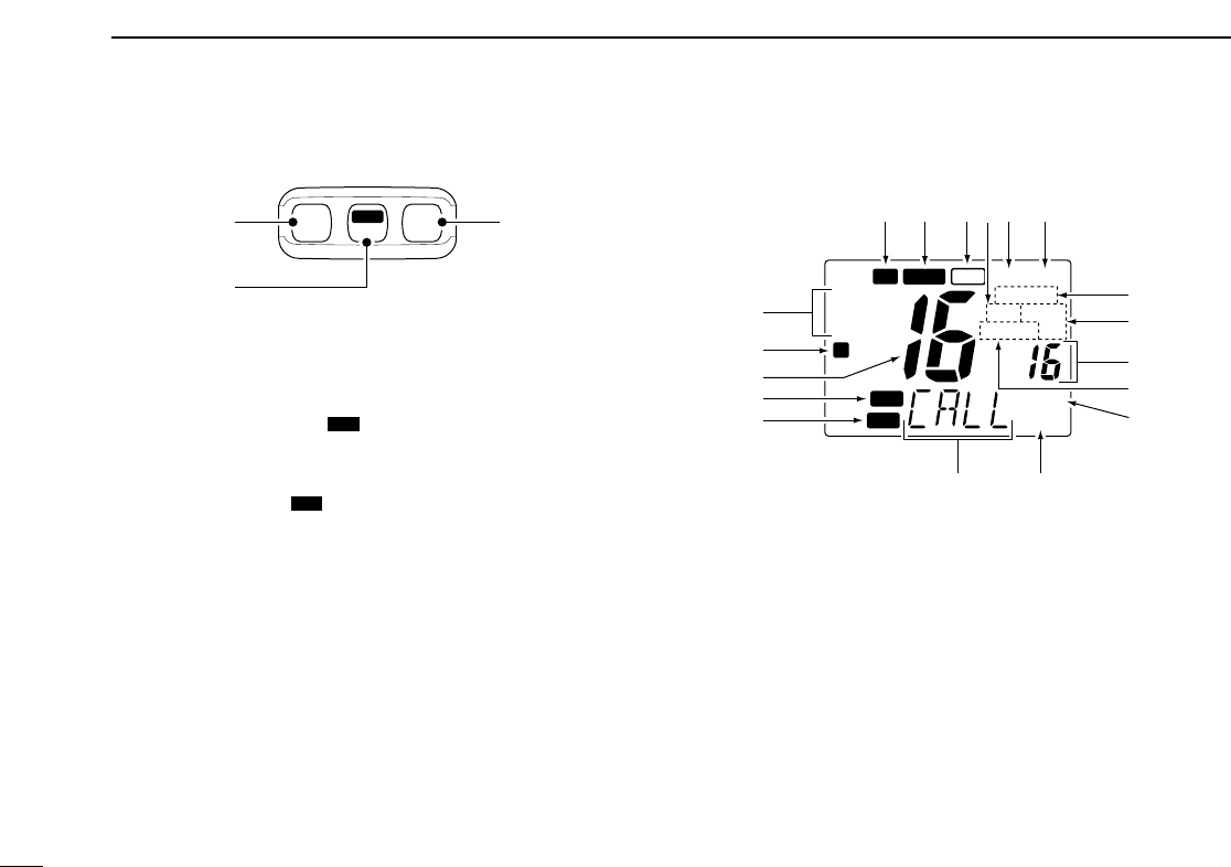
54
13 HM-127 REMOTE-CONTROL MICROPHONE
DDTop keys
qPOWER KEY [PWR] (pgs. 8, 57)
Push for 2 sec. to turn the HM-127 power ON or OFF
when the IC-M502A power is turned ON.
wSCAN KEY [
[SCAN
SCAN]
](
()
)(pgs. 13, 61)
➥Starts and stops Normal or Priority scan when tag chan-
nels are programmed.
➥Push [
[SCAN
SCAN]
](
()
)for 1 sec. to set the displayed chan-
nel as a tag (scanned) channel.
➥While pushing [
[H/L
H/L]
], push for 3 sec. to clear or set all
tag channels.
eTRANSMIT POWER KEY [
[H/L
H/L]
]
➥Toggles high or low power when pushed. (pgs. 8, 57)
• Some Channels are set to low power only.
➥While pushing this key, other keys perform secondary
functions.
➥Toggles the All key lock function ON or OFF when
pushed while turning power ON. (p. 58)
•“ T” blinks while the All key lock function is in use.
•Only [
[PWR
PWR]
]and [
[PTT
PTT]
]function when the All key lock func-
tion is in use.
■Function display
qCHANNEL GROUP INDICATOR (pgs. 7, 56)
Indicates whether an International (INT), U.S.A. (USA) or
Canadian (CAN) channel is selected.
wKEY LOCK INDICATOR (p. 58)
➥Appears while the Key lock function is in use.
➥Blinks while the All key lock function is in use.
CALL
WX ALT
DUP
P SCAN
SCRM
LOCAL
TRI
DUAL
LOW
TAG
CAN
USA
INT
L
TX BUSY
VOL
SQL
q
w
r
t
e
!8 !7 !4!5 !3
!2
!1
!0
o
i
uy
!6
TAG
TAG
PWR SCAN H/L
TAG
qe
w

55
13
HM-127 REMOTE-CONTROL MICROPHONE
eCHANNEL NUMBER READOUT
➥Indicates the selected operating channel number.
“A” appears when a simplex channel is selected. “b” ap-
pears when a receive only channel for a Canadian chan-
nel group is selected. (pgs. 6, 56)
➥In Set mode, indicates the selected condition. (pgs. 38,
62)
rVOLUME INDICATOR (p. 57)
Appears while audio output level is adjusted.
tSQUELCH INDICATOR (p. 57)
Appears while noise squelch level is adjusted.
yCHANNEL COMMENT INDICATOR
➥Channel comment appears (and scrolls) if programmed.
(pgs. 9, 63)
➥In Set mode, indicates or scrolls the selected Set mode
item. (pgs. 38, 62)
uATTENUATOR INDICATOR (pgs. 8, 57)
Appears when the RF Attenuator is in use.
iSCRAMBLER INDICATOR (pgs. 10, 60)
Appears when an optional Voice scrambler is activated.
oSCAN INDICATOR (pgs. 13, 61)
➥“SCAN” appears during Normal scan.
➥“P SCAN” appears during Priority scan.
!0 PRIORITY CHANNEL INDICATOR
➥Indicates a priority channel during Priority scan or
Dual/Tri-watch. (pgs. 11, 13, 60, 61)
➥“IC” appears during Intercom mode. (pgs. 36, 63)
!1 DUAL/TRI WATCH INDICATOR (pgs. 11, 60)
“DUAL” appears during Dualwatch; “TRI” during Tri-watch.
!2 WEATHER CHANNEL INDICATOR (pgs. 7, 56)
➥“WX” appears when a weather channel is selected.
➥“WX ALT” appears when the Weather alert function is in
use; blinks when an alert tone is received.
!3 LOW POWER INDICATOR (pgs. 8, 57)
Appears when low power is selected.
!4 CALL CHANNEL INDICATOR (pgs. 6, 56)
Appears when call channel is selected.
!5 DUPLEX INDICATOR (pgs. 7, 56)
Appears when a duplex channel is selected.
!6 TAG CHANNEL INDICATOR (pgs. 13, 61)
Appears when a tag channel is selected.
!7 BUSY INDICATOR (pgs. 8, 57, 59)
Appears when receiving a signal or when the squelch
opens.
!8 TRANSMIT INDICATOR (pgs. 8, 57)
Appears while transmitting.
13
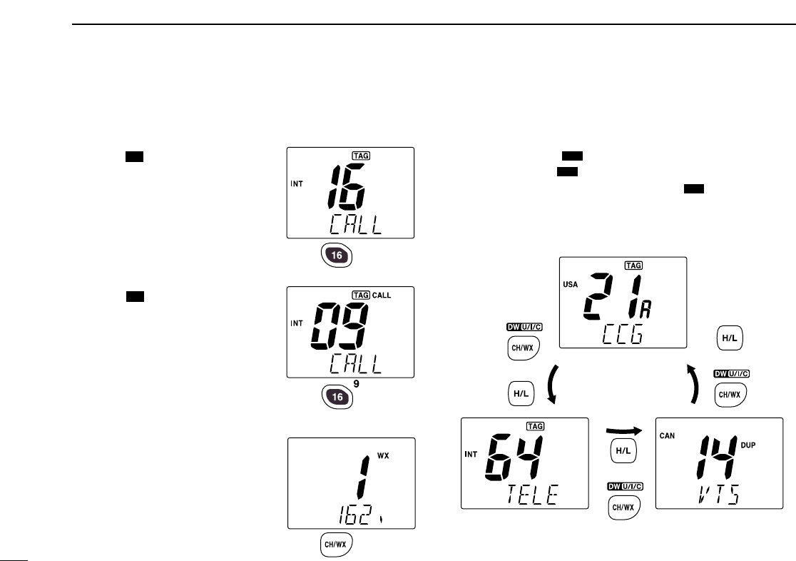
56
13 HM-127 REMOTE-CONTROL MICROPHONE
■Channel selection
DDChannel 16
qPush [
[]
]to select Channel 16.
wPush [
[CH/WX
CH/WX]
]to return to the
condition before selecting Chan-
nel 16, or push [
[YY
YY]
]or [
[ZZ
ZZ]
]to se-
lect an operating channel.
DDCall channel
qPush [
[]
](
(9
9)
)for 1 sec. to select
call channel.
wPush [
[CH/WX
CH/WX]
]to return to the
condition before selecting call
channel, or push [
[YY
YY]
]or [
[ZZ
ZZ]
]to
select an operating channel.
DDWeather channels
qPush [
[CH/WX
CH/WX]
]once or twice to
select the weather channel group.
wPush [
[YY
YY]
]or [
[ZZ
ZZ]
]to select a
weather channel.
ePush [
[CH/WX
CH/WX]
]to return to the
condition before selecting the
weather channel group.
DD
U.S.A., International and Canadian channels
qPush [
[CH/WX
CH/WX]
](
(U/I/C)
U/I/C) to select a regular channel.
• Push [
[CH/WX
CH/WX]
](
(U/I/C)
U/I/C) again, if a weather channel appears.
wWhile pushing [
[H/L
H/L]
], push [
[CH/WX
CH/WX]
](
(U/I/C)
U/I/C) to select a
channel group.
• U.S.A., International and Canadian channels can be selected in
sequence.
DW
DW
DW
16
16
16
16
Push
Push for 1 sec.
Push
Push
while pushing
U.S.A. channels
Canadian channelsInternational channels
+
+
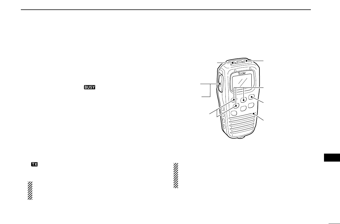
57
13
HM-127 REMOTE-CONTROL MICROPHONE
13
■Receiving and transmitting
qPush [
[PWR
PWR]
]to turn power ON.
wPush [
[VOL
VOL]
], then [
[YY
YY]
]/[
[ZZ
ZZ]
]to adjust audio output level.
• Push [
[SQL
SQL]
], then push [
[YY
YY]
]/[
[ZZ
ZZ]
]to mute any audio noise, if nec-
essary.
ePush [
[YY
YY]
]/[
[ZZ
ZZ]
]to select the desired channel.
•When receiving a signal, “ ” appears and audio is emitted
from the speaker.
• Further adjustment of the audio level may be necessary at this
point.
• Use the optional Voice scrambler function for privacy. (pgs. 10, 60)
rPush [
[H/L
H/L]
]to select the output power, if necessary.
• “LOW” appears when low power is selected.
• Choose low power for short range communications, choose high
power for longer distance communications.
• Some channels are for selecting low power only.
tPush and hold [
[PTT
PTT]
]to transmit, then speak into the mi-
crophone.
• “ ” appears.
• Channel 70 cannot be used for transmission other than DSC.
Simplex channels, 3, 21, 23, 61, 64, 81, 82 and 83
CANNOT be lawfully used by the general public in
U.S.A. waters.
yRelease [
[PTT
PTT]
]to receive.
IMPORTANT: To maximize the readability of your trans-
mitted signal (voice), pause a few sec. after pushing
[
[PTT
PTT]
], hold the microphone 2 to 4 inches (5 to 10 cm)
from your mouth and speak at a normal voice level.
w Set volume
w Set squelch,
if required
r Set output power
t Speak into
microphone
q Turn power ON
e Set channel
t Push to
transmit
y Release
to receive
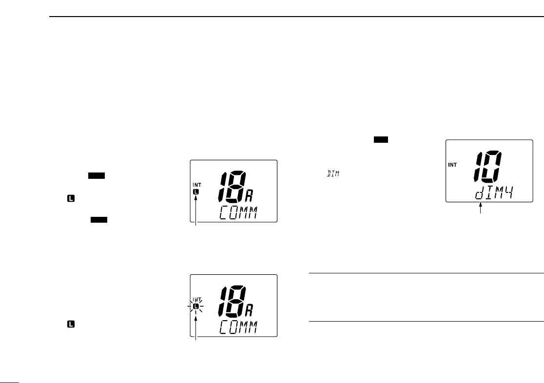
58
13 HM-127 REMOTE-CONTROL MICROPHONE
■Lock functions
The Lock function electronically locks keys and switches to
prevent accidental changes and function access from the mi-
crophone.
• All keys, switches and controllers on the transceiver are functional.
DDActivating the Lock function
➥While pushing [
[H/L
H/L]
], push
[
[SQL
SQL]
](
(L)
L) to turn the Lock
function ON or OFF.
• “ ” appears.
•
Only [
[PWR
PWR]
], [
[PTT
PTT]
], [
[H/L
H/L]
],
[
[SQL
SQL]
]
(
(L)
L)
, [
[VOL
VOL]
]+[
[YY
YY]
]/[
[ZZ
ZZ]
]
and [
[SQL
SQL]
]+[
[YY
YY]
]/[
[ZZ
ZZ]
]are func-
tional.
DDActivating the All key lock function
➥While pushing [
[H/L
H/L]
], turn the
power ON by pushing [
[PWR
PWR]
]
to turn the All key lock function
ON or OFF.
• “ ” blinks.
•Only [
[PWR
PWR]
]and [
[PTT
PTT]
]are
functional.
■Display backlighting
The function display and keys can be backlit for better visibil-
ity under low light conditions. The backlighting condition can
also be adjusted independently from the transceiver.
qPush [
[VOL
VOL]
](
()
)for 1 sec.
to enter Backlight adjusting
mode.
•“ ” with the number of the
backlight level appears in the
channel comment indicator.
wPush [
[YY
YY]
]/[
[ZZ
ZZ]
]to adjust the
backlight level.
• The backlight level is adjustable
between 0 (light OFF) and 7
(brightest).
For your reference:
Pushing [
[YY
YY]
]/[
[ZZ
ZZ]
], while [H/L]
[H/L] is pushed, also adjusts back-
light level.
• No backlight level indication is available.
DIM
MONI
MONI
Appears when the lock
function is in use.
Appears while in the
Backlight adjustment
mode.
Blinks when the all lock
function is in use.
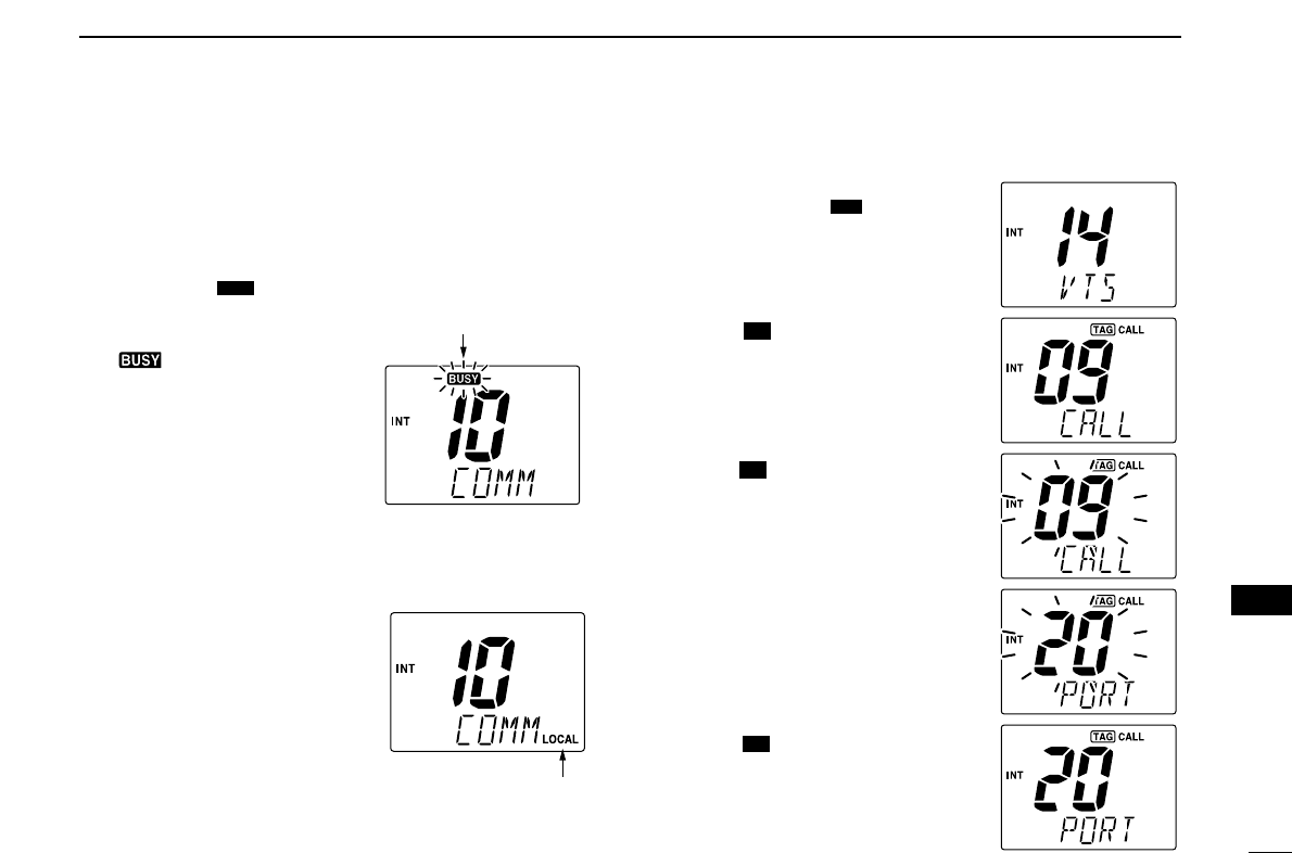
59
13
HM-127 REMOTE-CONTROL MICROPHONE
■Monitor function
The monitor function releases the noise squelch mute of the
microphone only. (An independent noise squelch system is
employed.)
■RF attenuator function
➥Push [
[LO/DX
LO/DX]
]to turn the RF
attenuator function ON and
OFF.
■Call channel programming
qPush [
[CH/WX
CH/WX]
](
(U/I/C)
U/I/C) several
times while pushing [
[H/L
H/L]
]to select
the desired channel group (USA,
INT, CAN) to be programmed.
wPush [
[]
](
(9
9)
)for 1 sec. to select
call channel of the selected chan-
nel group.
•“CALL” and call channel number ap-
pear.
ePush [
[]
](
(9
9)
)again for 3 sec. (until
a long beep changes to 2 short
beeps) to enter call channel pro-
gramming condition.
•The channel number and channel
group to be programmed blinks.
rPush [
[YY
YY]
]/[
[ZZ
ZZ]
]to select the desired
channel.
tPush [
[]
](
(9
9)
)to program the dis-
played channel as call channel.
•The channel number and channel
group stop flashing.
16
16
16
16
16
16
DW
13
Appears when the RF
attenuator function is
in use.
Blinks when the Monitor
function is in use.
➥Push [
[SQL
SQL]
](
(L)
L) for 1 sec.
to activate the Monitor func-
tion.
• “ ” blinks and audio is emit-
ted.
•Any key cancels the Monitor
function.
MONI
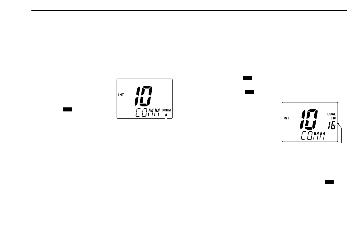
60
13 HM-127 REMOTE-CONTROL MICROPHONE
■Optional Voice scrambler
operation
DDActivating the Scrambler
qSelect an operating channel,
except for Channel 16, Chan-
nel 70 or weather channels.
wWhile pushing [
[H/L
H/L]
], push
[
[LO/DX
LO/DX]
](
(SCR)
SCR)
to turn the
Voice scrambler function ON.
• “SCRM” appears.
eTo turn the Scrambler func-
tion OFF, repeat step w.
• “SCRM” disappears.
DDProgramming scramble codes
There are 128 codes available with UT-98 or 32 codes (01
to 32) available with the UT-112 for programming. In order to
understand one another, all transceivers in your group must
have the same scrambler code as well as the same scram-
bler unit. The scrambler code is programmed in Set mode.
See pgs. 10, 41 for details.
■Dualwatch/Tri-watch
operation
qPush [
[YY
YY]
]/[
[ZZ
ZZ]
]to select the desired channel.
• Push [
[CH/WX
CH/WX]
](
(U/I/C)
U/I/C) several times while pushing [
[H/L
H/L]
]to
select the channel group (USA, INT, CAN), if desired.
wPush [
[CH/WX
CH/WX]
](
(U/I/C)
U/I/C) for 1 sec. to start Dualwatch or
Tri-watch.
•“DUAL” appears during Dual-
watch; “TRI” appears during Tri-
watch.
• A beep tone sounds when a sig-
nal is received on Channel 16.
•Tri-watch becomes Dualwatch
when receiving a signal on call
channel.
•Dualwatch or Tri-watch can be
selected in the transceiver’s Set
mode.
eTo cancel Dualwatch/Tri-watch, push [
[CH/WX
CH/WX]
](
(U/I/C)
U/I/C)
again.
DW
DW
DW
IC
Appears when the Voice
scrambler function is in use
Appears when the Dual or
Tri-watch function is in use.
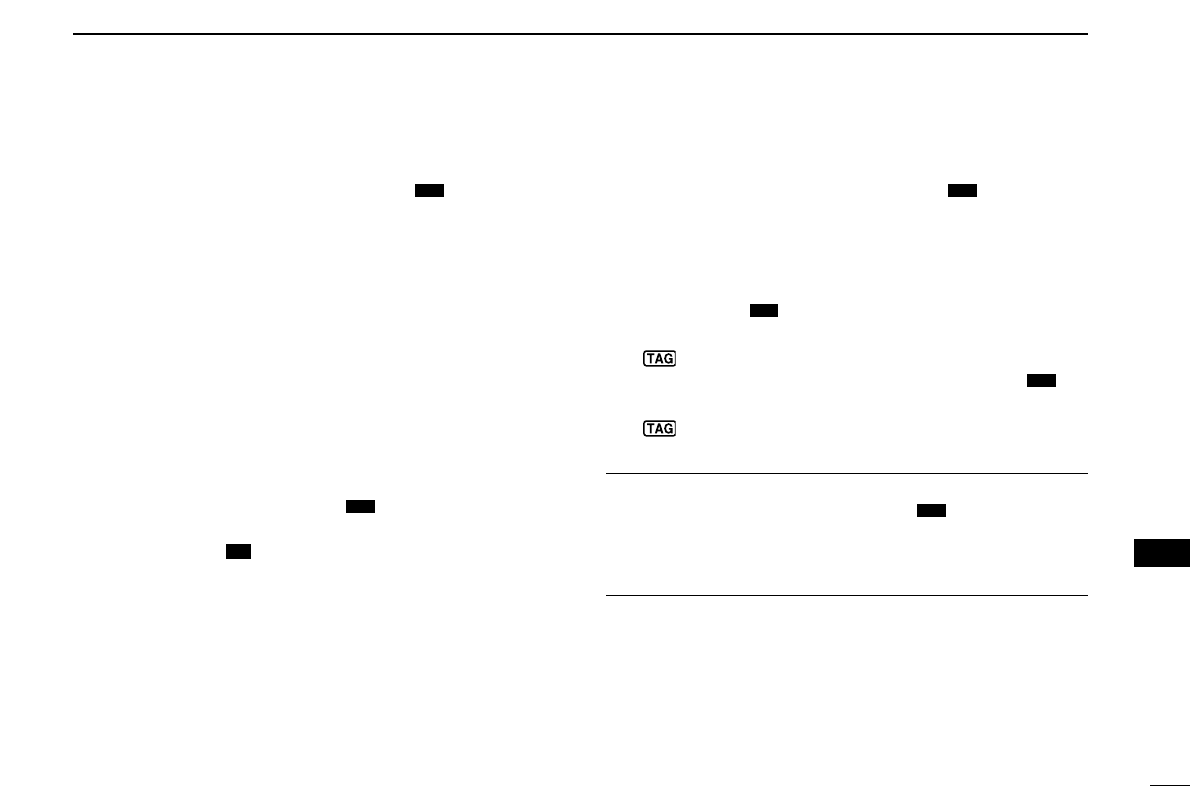
61
13
HM-127 REMOTE-CONTROL MICROPHONE
■Starting a scan
qWhile pushing [
[H/L
H/L]
], push [
[CH/WX
CH/WX]
](
(U/I/C)
U/I/C) several
times to select the channel group (USA, INT, CAN), if de-
sired.
•When the Weather alert function is in use, select the desired
weather channel with [
[CH/WX
CH/WX]
]and [
[YY
YY]
]/[
[ZZ
ZZ]
].
wPush [
[SCAN
SCAN]
]to start Priority or Normal scan.
• “SCAN” appears during Normal scan.
• The priority channel readout indicates “16”, and “P” and “SCAN”
indicators appear during Priority scan.
•When a signal is received, scan pauses until the signal disap-
pears or resumes after pausing 5 sec. according to the Set mode
setting (Channel 16 is still monitored during Priority scan).
• Push [
[YY
YY]
]/[
[ZZ
ZZ]
]to check the scanning tag channels, to change the
scanning direction or resume the scan manually.
e
To stop the scan, push [
[SCAN
SCAN]
](
()
).
• “SCAN” disappears.
• Pushing [
[PTT
PTT]
], [
[]
](
(9
9)
)or [
[CH/WX
CH/WX]
]also stops the scan.
■Setting tag channels
qWhile pushing [
[H/L
H/L]
], push [
[CH/WX
CH/WX]
](
(U/I/C)
U/I/C) several
times to select the channel group (USA, INT, CAN), if de-
sired.
wPush [
[YY
YY]
]/[
[ZZ
ZZ]
]to select the desired channel to set as a tag
channel.
ePush [
[SCAN
SCAN]
](
()
)for 1 sec. to set the displayed channel
as a tag channel.
• “ ” appears.
rTo cancel the tag channel setting, push [
[SCAN
SCAN]
](
()
)for
1 sec.
• “ ” disappears.
Convenient: Clearing (setting) all tagged channels
➥While pushing [
[H/L
H/L]
], push [
[SCAN
SCAN]
](
()
)for 3 sec. (until a
long beep changes to 2 short beeps) to clear all tag
channels setting in the channel group.
• Repeat above procedure to set all tag channels.
TAG
TAG
TAG
DW
16
16
TAG
DW
13
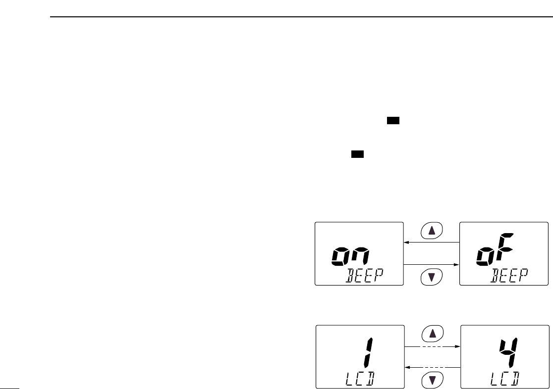
62
13 HM-127 REMOTE-CONTROL MICROPHONE
■Set mode programming
Set mode is used to change the condition of the transceiver’s
functions and the microphone’s own functions:
Transceiver’s functions—
scan mode (Normal or Priority), scan resume timer, weather
alert, Dualwatch/Tri-watch, DSC watch, transceiver’s beep
tone, internal speaker (transceiver), LCD contrast (trans-
ceiver), RF attenuation level, scrambler code, scrambler type
and automatic acknowledgement.
Microphone’s own functions—
beep tone function (microphone) and LCD contrast (micro-
phone).
In this section, instructions are for the microphone’s own func-
tions only. Refer to pgs. 38–41 for the setting of the other
functions. (Some functions cannot be selected from the HM-
127.)
DDEntering Set mode
qTurn power OFF.
wWhile pushing [
[]
](
(9
9)
), turn power ON.
•After a beep emission, a Set mode item (in the channel comment in-
dicator and the condition in the channel number readout) is displayed.
ePush [
[]
](
(9
9)
)to select the desired item, if necessary.
rPush [
[YY
YY]
]/[
[ZZ
ZZ]
]to select the desired condition of the item.
tTurn power OFF, then ON to exit Set mode.
•Beep tone “BEEP”
➥Push [
[YY
YY]
]to turn ON, [
[ZZ
ZZ]
]to turn OFF the beep output.
•LCD contrast “LCD CONTRAST”
➥Push [
[YY
YY]
]/[
[ZZ
ZZ]
]to adjust to a suitable LCD contrast.
Push
Push
16
16
16
16
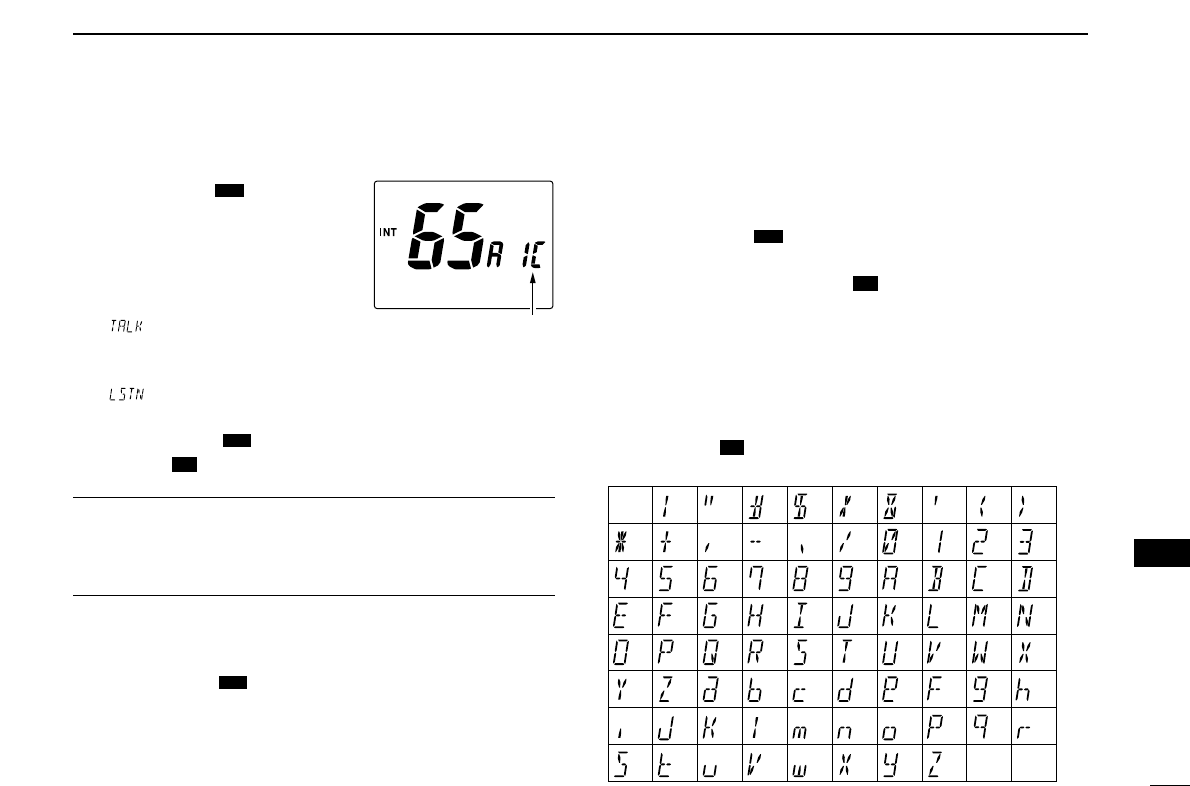
63
13
HM-127 REMOTE-CONTROL MICROPHONE
13
■Intercom operation
qPush
[
[LO/DX
LO/DX]
](
(SCR)
SCR)
for 1 sec.
to activate the Intercom function.
•“IC” appears in the priority channel
readout.
• The channel comment disappears.
wPush [
[PTT
PTT]
]to talk.
• “ ” appears in the channel com-
ment indicator.
eRelease [
[PTT
PTT]
]to listen.
•“ ” appears in the channel comment indicator when the
transceiver is in talking mode.
rPush [
[LO/DX
LO/DX]
](
(SCR)
SCR) to cancel the Intercom function.
• Pushing [
[]
]also cancels the Intercom function.
For your reference:
In case the Intercom mode is selected with the transceiver
while the microphone power is OFF, the microphone power is
automatically turned ON and the Intercom mode is selected.
DDIntercom beep function
➥Push [
[LO/DX
LO/DX]
](
(SCR)
SCR) for more than 1 sec.
• Emits the Intercom beep while holding.
■Channel comments
qPush [
[YY
YY]
]/[
[ZZ
ZZ]
]to select a channel to program a channel
comment.
• Push [
[CH/WX
CH/WX]
](
(U/I/C)
U/I/C) several times while pushing [
[H/L
H/L]
]to
select the channel group (USA, INT, CAN), if desired.
wWhile pushing [
[H/L
H/L]
], push [
[]
](
(9
9)
).
• The 1st character of the currently programmed comment blinks.
ePush [
[YY
YY]
]/[
[ZZ
ZZ]
]to select a character.
rPush [
[SQL
SQL]
]to move to forward; then push [
[YY
YY]
]/[
[ZZ
ZZ]
]to se-
lect a character.
• Push [
[VOL
VOL]
]to move to backward.
tContinue until the desired characters have been selected,
then push [
[]
](
(9
9)
)to return to normal operation.
•Available characters
16
16
16
16
DW
IC
16
16
IC
IC
(r)
(s) (t) (u) (v) (w) (x) (y) (z)
(q)
(3)
(D)
(N)
(X)
(h)
(+)
(4)
(E)
(O)
(Y)
(i)
(–)
(5)
(F)
(P)
(Z)
(j)
(✱)
(6)
(G)
(Q)
(a)
(k)
(/)
(7)
(H)
(R)
(b)
(l)
(,)
(8)
(I)
(S)
(c)
(m)
(space)
(9)
(T)
(d)
(n)
(0)
(A)
(U)
(e)
(o)
(1)
(B)
(V)
(f)
(p)
(2)
(C)
(J) (K) (L)
(M)
(W)
(g)
(.)
(
))((
)(’)(&)(
%
)($)(#)(")(!)
Appears when the inter-
com function is in use.
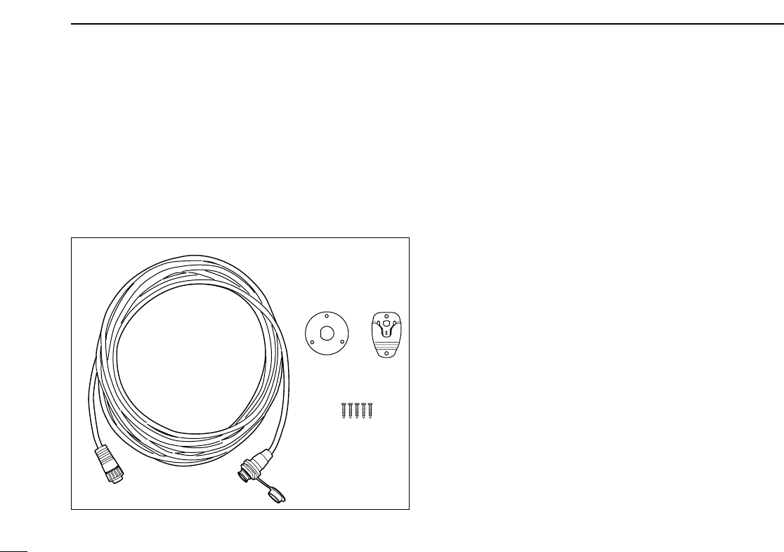
64
13 HM-127 REMOTE-CONTROL MICROPHONE
■HM-127 supplied accessories
Accessories included with the HM-127: Qty.
qConnection cable (OPC-1000: 6 m; 20 ft) ...................... 1
wMounting base ................................................................ 1
eMicrophone hanger ........................................................ 1
rScrews (M3 ×16; tapping) ............................................. 5
q
we
r
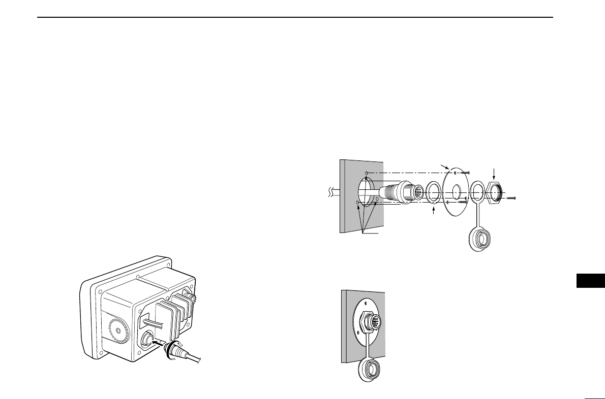
65
13
HM-127 REMOTE-CONTROL MICROPHONE
■Installation
The optional HM-127 can be connected to the transceiver di-
rectly, as well as via the supplied connection cable for longer
distance remote operation. The connector of the connection
cable can be installed into a cabinet, wall, etc., as a built-in
plug.
For longer distance remote operation, the optional extension
cable, OPC-999 (6 m; 20 ft/connecting between transceiver
and the connection cable), is available, and up to 2 OPC-999
can be added.
qInsert the supplied cable into the external microphone jack
and tighten the cable nut as shown below.
wTo use the supplied cable as a wall socket, follow the
below steps.
eUsing the mounting base, carefully mark off the 2 spots
where the cable and screws will be fastened.
rDrill holes at these marks.
tInstall the mounting base using the supplied screws as
shown below.
yThe completed installation should look like this.
Gasket
Cap
Mounting base Nut
Screw holes
(approx. 2 (d) mm; 3⁄32″)
13
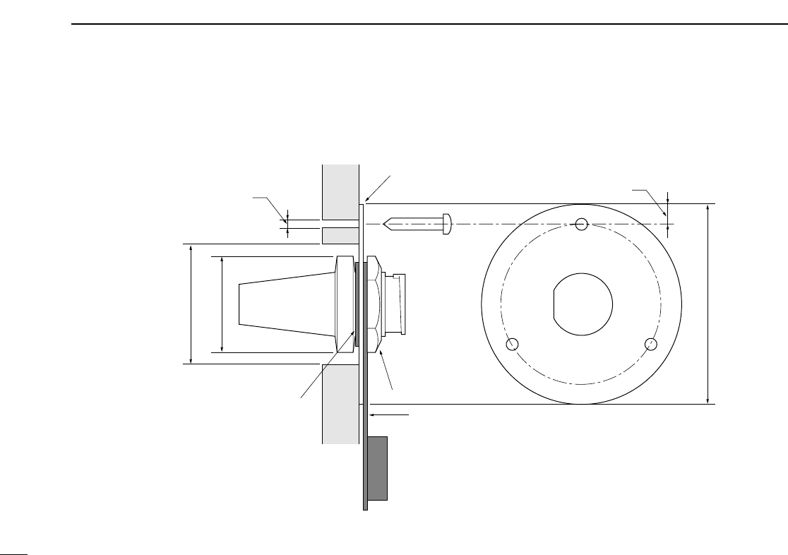
66
13 HM-127 REMOTE-CONTROL MICROPHONE
50 (d) mm; 131⁄32˝
23 (d) mm; 29⁄32˝
24 to 27 (d) mm
(15⁄16 to 11⁄16˝)
5 mm; 3⁄16˝
Gasket
Mounting base
Cap
Nut
2 mm; 3⁄32˝
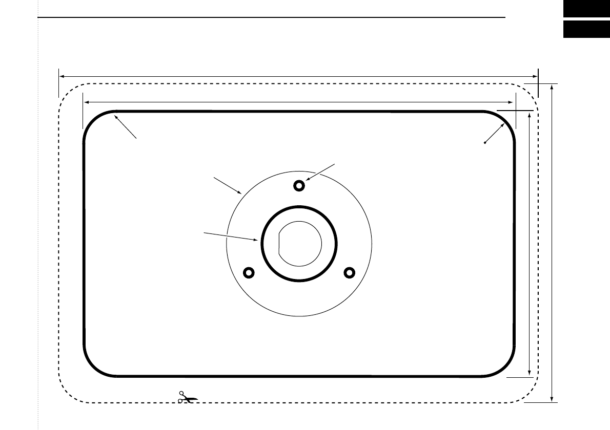
TEMPLATE
149 mm (57⁄8 in)
165 mm (61⁄2 in)
92 mm (35⁄8 in)
110 mm (411⁄32 in)
4–R11
24 to 27 (d) mm
(15⁄16 to 11⁄16 in)
2 mm; 3⁄32 in
MB-75
HM-127
Cut here

1-1-32 Kamiminami, Hirano-ku, Osaka 547-0003, Japan
A-6301H-1EX
Printed in Japan
© 2003 Icom Inc.