ICOM orporated 269800 Amateur Transceiver with Scanning Receiver User Manual
ICOM Incorporated Amateur Transceiver with Scanning Receiver Users Manual
UserManual.wiki
>
ICOM orporated
>
269800 User Manual
Users Manual
Navigation menu
Upload a User Manual
Namespaces
Wiki Guide
HTML
PDF
Info
Views
User Manual
Discussion / Help
Navigation
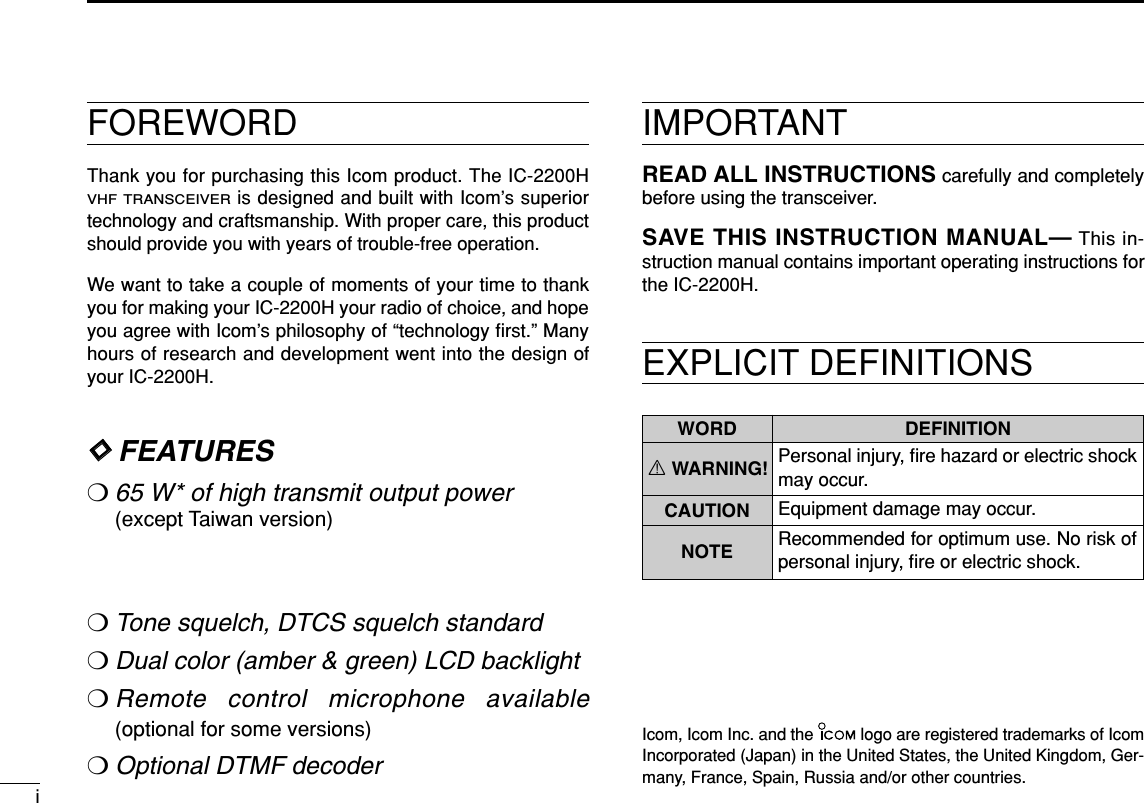
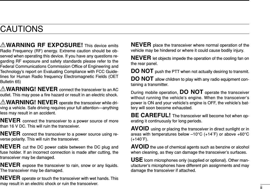
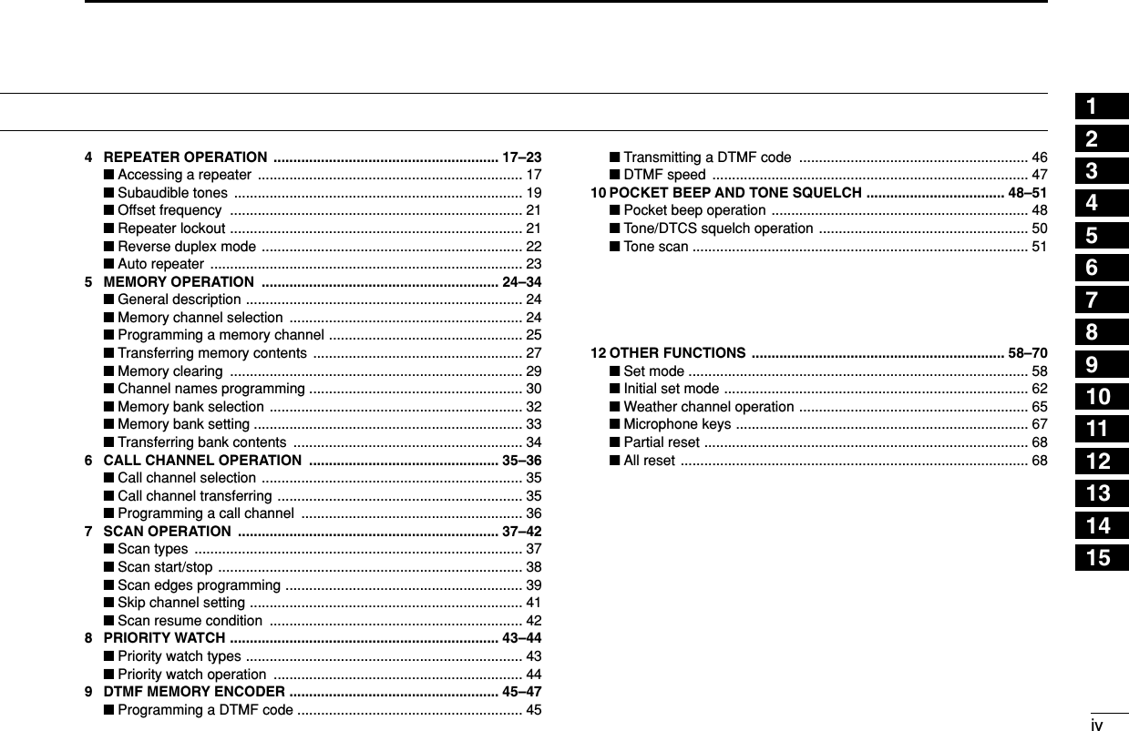
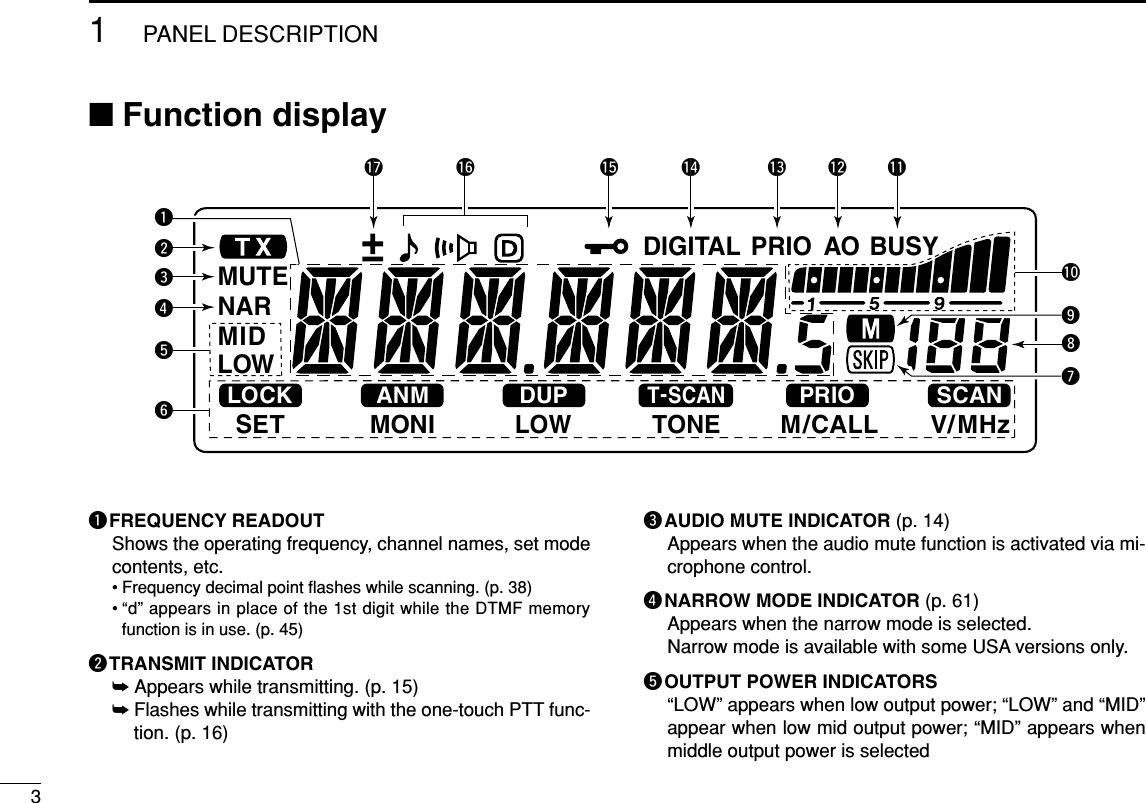
![iiiTABLE OF CONTENTSSUPPLIED ACCESSORIESqDC power cable (3 m) . . . . . . . . . . . . . . . . . . . . . . . . . . . 1wMobile mounting bracket . . . . . . . . . . . . . . . . . . . . . . . . 1eMicrophone (HM-133V)* . . . . . . . . . . . . . . . . . . . . . . . . . 1rFuse (20 A) . . . . . . . . . . . . . . . . . . . . . . . . . . . . . . . . . . . 1tMounting screws, nuts and washers . . . . . . . . . . . . 1 setyMicrophone hanger†. . . . . . . . . . . . . . . . . . . . . . . . . . . . 1*HM-118N HAND MICROPHONEor HM-118TN/TAN DTMF MICROPHONEsupplied versions are also available.†Depending on version.qw ertyFOREWORD ........................................................................................... iIMPORTANT ............................................................................................ iEXPLICIT DEFINITIONS ......................................................................... iCAUTIONS ............................................................................................. iiSUPPLIED ACCESSORIES .................................................................. iiiTABLE OF CONTENTS ......................................................................... iiiQUICK REFERENCE GUIDE ............................................................ I–VI■Installation ....................................................................................... I■Your first contact ........................................................................... IV■Repeater operation ........................................................................ V■Programming memory .................................................................. VI1 PANEL DESCRIPTION ................................................................. 1–8■Front panel ..................................................................................... 1■Function display ............................................................................. 3■Rear panel ..................................................................................... 5■Microphone (HM-133V) .................................................................. 6■Microphone keypad ........................................................................ 72 SETTING A FREQUENCY .......................................................... 9–12■Preparation .................................................................................... 9■Using the tuning dial ...................................................................... 9■Using the keypad ......................................................................... 10■Using the [Y]/[Z] keys ................................................................. 10■Tuning step selection ................................................................... 11■Lock functions .............................................................................. 123 BASIC OPERATION ................................................................. 13–16■Receiving ..................................................................................... 13■Monitor function ........................................................................... 13■Audio mute function ..................................................................... 14■Squelch attenuator ....................................................................... 14■Transmitting ................................................................................. 15■Selecting output power ................................................................ 15■One-touch PTT function ............................................................... 16](https://usermanual.wiki/ICOM-orporated/269800/User-Guide-381881-Page-4.png)
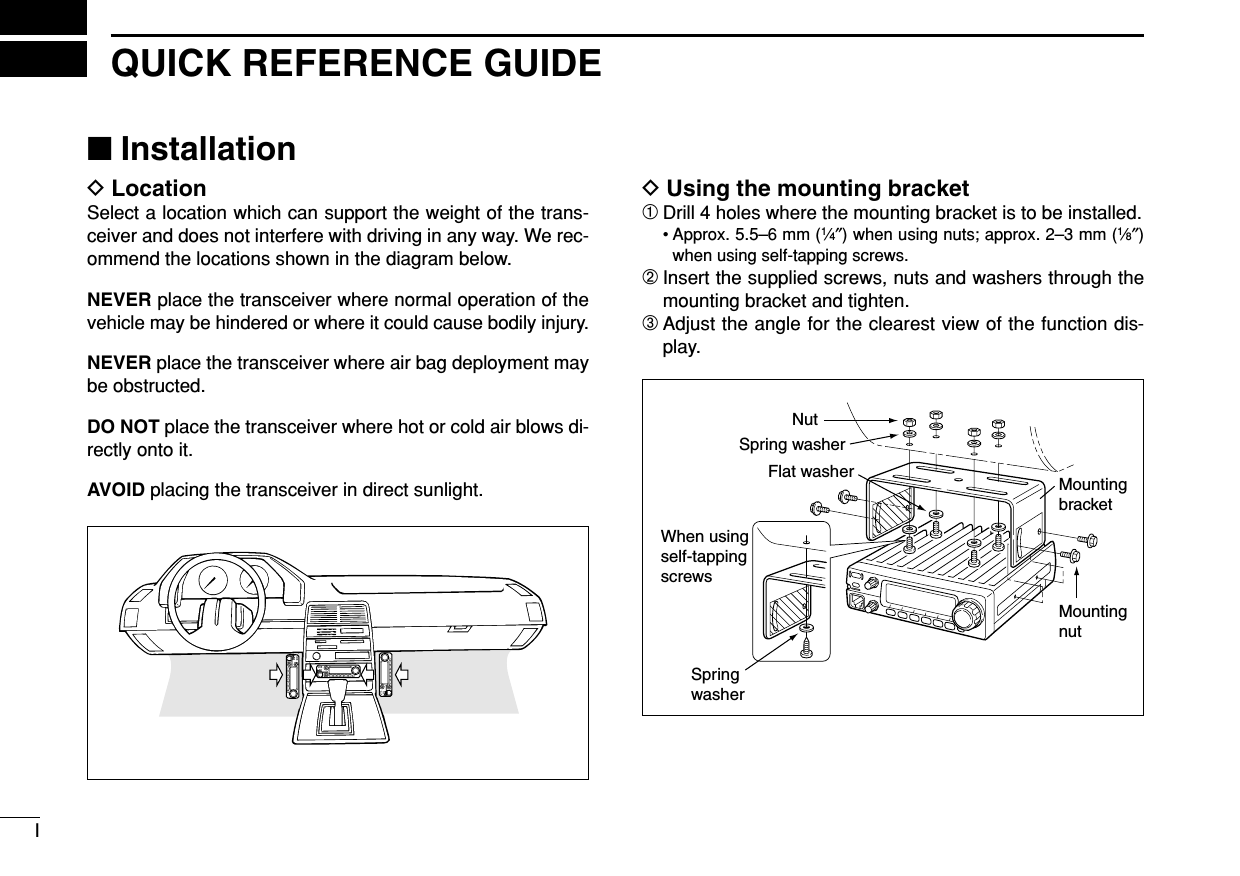
![IVQUICK REFERENCE GUIDE■Your first contactNow that you have your IC-2200H installed in your car orshack, you are probably excited to get on the air. We wouldlike to take you through a few basic operation steps to makeyour first “On The Air” an enjoyable experience. 1. Turning ON the transceiverBefore powering up your IC-2200H, you may want to makesure the audio volume and squelch level controls are set in9–10 o’clock positions.Although you have purchased a brand new transceiver, somesettings may be changed from the factory defaults becauseof the QC process. Resetting the CPU is necessary to startfrom factory default.➥While pushing [SET ] and [S.MW ], push[PWR] for 1 sec. to reset the CPU.2. Tune the desired frequency[DIAL] will allow you to dial in the frequency you want to op-erate. Pages 9 and 11 will instruct you on how to set the tun-ing speed.Using the HM-133VYou can directly enter the frequency with the HM-133V keypad. We hope these pointers have been helpful. Now youare ready to call CQ.LOCKSETANMMONIDUPLOWT-SCANTONEPRIOM/CALLSCANV/MHzDIGITAL PRIO AO BUSYMUTENARMIDLOWLOCKSETANMMONIDUPLOWT-SCANTONEPRIOM/CALLSCANV/MHzDIGITAL PRIO AO BUSYMUTENARMIDLOWLOCKSETANMMONIDUPLOWT-SCANTONEPRIOM/CALLSCANV/MHzDIGITAL PRIO AO BUSYMUTENARMIDLOWLOCKSETANMMONIDUPLOWT-SCANTONEPRIOM/CALLSCANV/MHzDIGITAL PRIO AO BUSYMUTENARMIDLOW[EXAMPLE]: Setting frequency to 145.3625 MHz.PushPushPushPush[DIAL]MWLOCK[PWR] [SET LOCK] [S.MW MW]Set both [VOL] and [SQL] controls to 9–10 o’clock positions.[VOL][SQL]](https://usermanual.wiki/ICOM-orporated/269800/User-Guide-381881-Page-9.png)
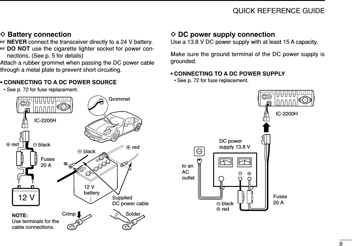
![VQUICK REFERENCE GUIDE■Repeater operation1. Setting duplex Push [LOW ] for 1 sec. once or twice to select minusduplex or plus duplex.• The USA and CSA versions have an auto repeater function, there-fore, setting duplex is not required.2. Repeater tone Push [TONE ] several times until “ ” appears, if therepeater requires a subaudible to be accessed.Using the HM-133VPlus or minus duplex selection and the repeater tone settingcan be made easily via HM-133V.Push [DUP–7(TONE)] for minus duplex; [DUP+8(TSQLSS)]for plus duplex selection, push [FUNC] then [DUP–7(TONE)]to turn the repeater tone ON.LOCKSETANMMONIDUPLOWT-SCANTONEPRIOM/CALLSCANV/MHzDIGITAL PRIO AO BUSYMUTENARMIDLOWLOCKSETANMMONIDUPLOWT-SCANTONEPRIOM/CALLSCANV/MHzDIGITAL PRIO AO BUSYMUTENARMIDLOWLOCKSETANMMONIDUPLOWT-SCANTONEPRIOM/CALLSCANV/MHzDIGITAL PRIO AO BUSYMUTENARMIDLOWPushPush , then PushLOCKSETANMMONIDUPLOWT-SCANTONEPRIOM/CALLSCANV/MHzDIGITAL PRIO AO BUSYMUTENARMIDLOWT-SCANLOCKSETANMMONIDUPLOWT-SCANTONEPRIOM/CALLSCANV/MHzDIGITAL PRIO AO BUSYMUTENARMIDLOWDUP](https://usermanual.wiki/ICOM-orporated/269800/User-Guide-381881-Page-10.png)
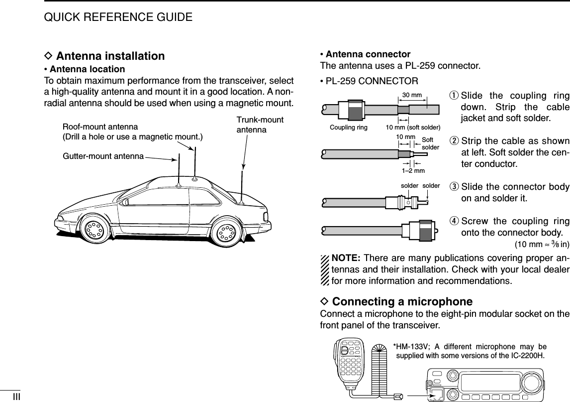
![VIQUICK REFERENCE GUIDE■Programming memorychannelsThe IC-2200H has a total of 200 memory channels (including6 scan edges and 1 call channel) for storing often used oper-ating frequency, repeater settings, etc. 1. Setting a frequencyIn VFO mode, set the desired operating frequency with re-peater, tone and tuning steps, etc. 2. Selecting a memory channel Momentarily push [S.MW ], then rotate [DIAL] to selectthe desired memory channel.•“M” indicator and memory channel number blink.3. Writing a memory channelPush and hold [S.MW ] for 1 sec. to program.• 3 beeps sound• Memory channel number automatically increases when continuingto push [S.MW ] after programming.Using the HM-133VqIn VFO mode, set the desired operating frequency, includ-ing offset direction, tone settings, etc.wPush [FUNC] then [CLRA(MW)].•“M” indicator and memory channel number blink.ePush [YY]/[ZZ]to select the desired memory channel.rPush [FUNC] then push [CLRA(MW)] for 1 sec. to pro-gram.• 3 beeps sound• Memory channel number automatically increases when continu-ing to push [CLRA(MW)] after programming.LOCKSETANMMONIDUPLOWT-SCANTONEPRIOM/CALLSCANV/MHzDIGITAL PRIO AO BUSYMUTENARMIDLOWPush , then MWMWLOCKSETANMMONIDUPLOWT-SCANTONEPRIOM/CALLSCANV/MHzDIGITAL PRIO AO BUSYMUTENARMIDLOW[S.MW MW] [DIAL]MW](https://usermanual.wiki/ICOM-orporated/269800/User-Guide-381881-Page-11.png)
![■Front panelqPOWER KEY [PWR]Turns power ON and OFF when pushed for 1 sec.wMEMORY WRITE KEY [S.MW ] (p. 25)➥Selects a memory channel for programming.➥Programs the selected memory channel when pushedfor 1 sec. • Continue to hold the key to increment the memory channelautomatically.eMICROPHONE CONNECTORConnects the supplied microphone. rVOLUME CONTROL [VOL]Adjusts the audio level. (p. 13)tSQUELCH CONTROL [SQL]Varies the squelch level. (p. 13)• The RF attenuator activates and increases the attenuation whenrotated clockwise to the center position and further.MWPWRS.MWMWBANKOPTFunction display (p. 4)!0oiuyqwert!3!1 !21PANEL DESCRIPTION1](https://usermanual.wiki/ICOM-orporated/269800/User-Guide-381881-Page-12.png)
![21PANEL DESCRIPTION1ySET•LOCK KEY [SET ]➥Enters set mode when pushed. (p. 58)➥Keys the lock function ON and OFF when pushed for1 sec. (p. 12)uMONITOR•CHANNEL NAME KEY [MONI ]➥Push to switch the monitor function ON and OFF. (p. 13)➥In memory and call channel mode, switches the channelnames or number ON and OFF. (p. 30)iOUTPUT POWER KEY [LOW ]➥Each push changes the output power selection. (p. 15)➥Select DUP–, DUP+ and simplex operation whenpushed for 1 sec. (p. 17)oTONE/TONE SCAN KEY [TONE ]➥Each push selects a tone function. (pgs. 17, 48)• Tone encoder, pocket beep, tone squelch or tone functionOFF can be selected.➥Push for 1 sec. to start/stop the tone scan function.(p. 51)!0 MEMORY/CALL•PRIORITY KEY [M/CALL ]➥Push to select and toggle memory, call and weatherchannel* modes. (pgs. 24, 35, 65)*Weather channels available for USA versions only.➥Starts priority watch when pushed for 1 sec. (p. 44)!1 VFO/MHz TUNING•SCAN KEY [V/MHz ]➥Selects and toggles VFO mode and 1 MHz (or 10 MHzfor some versions) tuning when pushed. (p. 9)➥Starts scan when pushed for 1 sec. (p. 38)• Cancels a scan when pushed during scan.!2 BANK•OPTION KEY [BANK ]➥Push to select memory bank condition during memorymode. (p. 32)➥Push for 1 sec. to select and toggle the pager and codesquelch function when the optional UT-108 is installed.(p. 52)!3 TUNING DIAL [DIAL]Selects the operating frequency (p. 9), memory channel(p. 24), the setting of the set mode item and the scanningdirection (p. 38).DMicrophone connector (front panel view)q+8 V DC output (Max. 10 mA)wChannel up/downe8 V control INrPTTtGND (microphone ground)yMIC (microphone input)uGNDiData INqiOPTSCANPRIOT-SCANDUPANMLOCK](https://usermanual.wiki/ICOM-orporated/269800/User-Guide-381881-Page-13.png)
![51PANEL DESCRIPTION■Rear panelqSPEAKER JACK [SP]Accepts an 8 Ωspeaker.• Audio output power is more than 2.4 W.wDATA JACK [DATA]Connects to a PC via an RS-232C cable (D-sub 9-pin) forremote control in the NMEA or RS-232C format.ePOWER RECEPTACLE [DC13.8V]Accepts 13.8 V DC ±15% with the supplied DC powercable.☞NOTE: DO NOT use a cigarette lighter socket as apower source when operating in a vehicle. The plugmay cause voltage drops and ignition noise may be su-perimposed onto transmit or receive audio.eCOOLING FAN Rotates while transmitting. Also rotates while receiving depending on the setting in setmode and transceiver’s temperature. (p. 61)rANTENNA CONNECTOR [ANT]Connects a 50 Ωantenna with a PL-259 connector and a50 Ωcoaxial cable.reqw](https://usermanual.wiki/ICOM-orporated/269800/User-Guide-381881-Page-16.png)
![61PANEL DESCRIPTION1■Microphone (HM-133V*)qVFO/LOCK KEY [VFO/LOCK]➥Push to select VFO mode. (p. 9)➥Push for 1 sec. to switch the lock function ON and OFF.(p. 12)wPTT SWITCH➥Push and hold to transmit; release to receive.➥Switches between transmitting and receiving while theone-touch PTT function is in use. (p. 16)eUP/DOWN KEYS [Y]/[Z]➥Push either key to change operating frequency, mem-ory channel, set mode setting, etc. (pgs. 10, 24)➥Push either key for 1 sec. to start scanning. (p. 38)rACTIVITY INDICATOR➥Lights red while any key, except [FUNC] and [DTMF-S],is pushed, or while transmitting.➥Lights green while the one-touch PTT function is in use.tKEYPAD (pgs. 7, 8)yFUNCTION INDICATOR➥Lights orange while [FUNC] is activated—indicates thesecondary function of keys can be accessed.➥Lights green when [DTMF-S] is activated—DTMF sig-nals can be transmitted with the keypad.uFUNCTION KEY [FUNC] (pgs. 7, 8)iDTMF MEMORY SELECT KEY [DTMF-S] (p. 46)oFUNCTION KEYS [F-1]/[F-2] (p. 67)Program and re-call your desired transceiver conditions.!0BANK/OPTION KEY [BANK/OPTION] ➥Push to selects memory bank condition during memorymode. (p. 32)➥Push for 1 sec. to select and toggle pager and codesquelch function when the optional UT-108 is installed.(p. 52)!1MEMORY/CALL KEY [MR/CALL]➥Push to select memory mode. (p. 24)➥Push for 1 sec. to select call channel. (p. 35)qertMic elementyuio!0!1w*A different microphonemay be supplied de-pending on version.](https://usermanual.wiki/ICOM-orporated/269800/User-Guide-381881-Page-17.png)
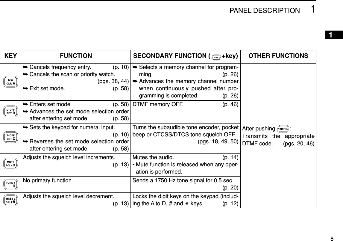
![71PANEL DESCRIPTION■Microphone keypadKEY FUNCTION SECONDARY FUNCTION ( +key) OTHER FUNCTIONSSwitches between opening and closing thesquelch. (p. 13)Starts and stops scanning. (p. 38)Starts and stops priority watch. (p. 44)Selects high output power. (p. 15)Selects mid. output power. (p. 15)Selects low output power (p. 15)Selects minus duplex operation. (p. 18)Selects plus duplex operation. (p. 18)Selects simplex operation. (p. 18)No primary function.In memory mode switches the channel namesor number indication ON and OFF. (p. 31)Starts and stops tone scanning. (p. 51)Turns the one-touch PTT function ON andOFF. (p. 16)Turns the DTCS squelch ON. (p. 50)Turns the DTCS pocket beep function ON.(p. 49)Turns the DTMF memory encoder functionON. (p. 45)Turns the subaudible tone encoder ON.(p. 18)Turns the CTCSS pocket beep functionON. (p. 49)Turns the tone squelch function ON.(p. 50)Sends a 1750 Hz tone signal while pushingand holding. (p. 20)After pushing :Transmits the appropriateDTMF code. (pgs. 20, 46)When the DTMF memory en-coder is activated, push [0] to[9] to transmit the appropriateDTMF memory contents .(p. 46)](https://usermanual.wiki/ICOM-orporated/269800/User-Guide-381881-Page-18.png)
![9SETTING A FREQUENCY2■PreparationDTurning power ON/OFF➥Push [PWR] for 1 sec. toturn power ON and OFF.DVFO mode selectionThe transceiver has 2 basic operating modes: VFO mode andmemory mode.➥Push [V/MHz ] toselect VFO mode.➥Push [VFO/LOCK] to select VFO mode.■Using the tuning dialqRotate [DIAL] to set the frequency.• If VFO mode is not selected, push [V/MHz ] to select VFOmode.• The frequency changes according to the selected tuning steps.(p. 11)wTo change the frequency in 1 MHz (10 MHz for some ver-sions) steps, push [V/MHz ], then rotate [DIAL].• Pushing [V/MHz ] for1 sec. starts scan function. If scan starts, push [V/MHz ] again to can-cel it.SCANSCANLOCKSETANMMONIDUPLOWT-SCANTONEPRIOM/CALLSCANV/MHzDIGITAL PRIO AO BUSYMUTENARMIDLOWThe display shows that the 1 MHz tuning step is selected.SCANSCANLOCKSETANMMONIDUPLOWT-SCANTONEPRIOM/CALLSCANV/MHzDIGITAL PRIO AO BUSYMUTENARMIDLOW[DIAL]VFO/LOCKSCANLOCKSETANMMONIDUPLOWT-SCANTONEPRIOM/CALLSCANV/MHzDIGITAL PRIO AO BUSYMUTENARMIDLOWPush [PWR] for 1 sec.Note that in this manual, sections beginning with a micro-phone icon (as above), designate operation via the HM-133V microphone.](https://usermanual.wiki/ICOM-orporated/269800/User-Guide-381881-Page-20.png)
![102SETTING A FREQUENCY2■Using the keypadThe frequency can be directly set via numeral keys on the mi-crophone.zPush [VFO/LOCK] to VFO mode, if necessary.xPush [ENTC(T-OFF)] to activate the keypad fordigit input.cPush 6 keys to input a frequency.• When a digit is mistakenly input, push [ENTC(T-OFF)]to clear the input, then repeat input from the 1st digit.• Pushing [CLRA(MW)] clears input digits and retrievesthe frequency.■Using the [Y]/[Z] keys➥Push [YY]or [ZZ]to select the desired frequency.• Pushing [YY]/[ZZ]for 1 sec. activates a scan. If scanstarts, push [YY]/[ZZ]again or push [CLRA(MW)] tocancel it.YZLOCKSETANMMONIDUPLOWT-SCANTONEPRIOM/CALLSCANV/MHzDIGITAL PRIO AO BUSYMUTENARMIDLOWLOCKSETANMMONIDUPLOWT-SCANTONEPRIOM/CALLSCANV/MHzDIGITAL PRIO AO BUSYMUTENARMIDLOWLOCKSETANMMONIDUPLOWT-SCANTONEPRIOM/CALLSCANV/MHzDIGITAL PRIO AO BUSYMUTENARMIDLOWLOCKSETANMMONIDUPLOWT-SCANTONEPRIOM/CALLSCANV/MHzDIGITAL PRIO AO BUSYMUTENARMIDLOW[EXAMPLE]: Setting frequency to 145.3625 MHz.PushPushPushPushENTC](https://usermanual.wiki/ICOM-orporated/269800/User-Guide-381881-Page-21.png)
![112SETTING A FREQUENCY■Tuning step selectionTuning steps are the minimum frequency change incrementswhen you rotate [DIAL] or push [YY]/[ZZ]on the microphone.The following tuning steps are available.• 5 kHz • 10 kHz • 12.5 kHz • 15 kHz• 20 kHz • 25 kHz • 30 kHz • 50 kHz☞NOTE: For convenience, select a tuning step that matchesthe frequency intervals of repeaters in your area.qPush [V/MHz ] to se-lect VFO mode, if neces-sary.wPush [SET ] to enterset mode.ePush [SET] or [MONI] sev-eral times until “TS” appearsas shown at left.rRotate [DIAL] to select thedesired tuning step.tPush [TONE ] toexit set mode.zPush [VFO/LOCK] to select VFO mode, ifnecessary.xPush [SETB(D-OFF)] to enter set mode.cPush [SETB(D-OFF)] or [ENTC(T-OFF)]several times until “TS” appears.vPush [YY]or [ZZ]to select the desired tun-ing step.bPush [CLRA(MW)] to exit set mode.VFO/LOCKT-SCANLOCKSCANLOCKSETANMMONIDUPLOWT-SCANTONEPRIOM/CALLSCANV/MHzDIGITAL PRIO AO BUSYMUTENARMIDLOW15 kHz tuning step[DIAL]USINGSET MODE](https://usermanual.wiki/ICOM-orporated/269800/User-Guide-381881-Page-22.png)
![122SETTING A FREQUENCY2■Lock functionsTo prevent accidental channel changes and unnecessaryfunction access, use the lock function. The transceiver has 2different lock functions.DFrequency lockThis function locks [DIAL] and keys electronically and can beused together with the microphone lock function.➥Push [SET ] for1 sec. to turn the lock func-tion ON and OFF.•[PTT], [MONI ], [VOL]and [SQL] can be used whilethe channel lock function is inuse. Also, TONE-1, TONE-2,DTMF tones or DTMF mem-ory contents can be transmit-ted from the microphone.➥Push [VFO/LOCK] for 1 sec. to switch thelock function ON and OFF.DMicrophone keypad lockThis function locks the microphone keypad.➥Push [FUNC] then [SQLZZ#(16KEY-L)] toswitch the microphone keypad lock functionON and OFF.•[PTT], [VFO/LOCK], [MR/CALL], [BANK/OP-TION], [YY], [ZZ], [F-1], [F-2], [DTMF-S] and[FUNC] on the microphone can be used.• All keys on the transceiver can be used.• The keypad lock function is released when thepower is turned OFF then ON again.16KEY-LVFO/LOCKANMLOCKLOCKSETANMMONIDUPLOWT-SCANTONEPRIOM/CALLSCANV/MHzDIGITAL PRIO AO BUSYMUTENARMIDLOWAppears](https://usermanual.wiki/ICOM-orporated/269800/User-Guide-381881-Page-23.png)
![13BASIC OPERATION3■ReceivingqPush [PWR] for 1 sec. to turn power ON.wSet the audio level.➥Push [MONI ] to open the squelch.➥Rotate the [VOL] control to adjust the audio outputlevel.➥Push [MONI ] again to close the squelch.eSet the squelch level.➥Rotate [SQL] fully counterclockwise in advance.➥Rotate [SQL] clockwise until the noise just disappears.➥When interference is received, rotate [SQL] clockwiseagain for attenuator operation.rSet the operating frequency. (pgs. 9, 10)tWhen receiving a signal on the set frequency, squelchopens and the transceiver emits audio.• “BUSY” appears and the S/RFindicator shows the relativesignal strength for the re-ceived signal.✔CONVENIENT!The squelch level can also be adjusted with[SQLYYD(MUTE)] and [SQLZZ#(16KEY-L)].■Monitor functionThis function is used to listen to weak signals without disturb-ing the squelch setting or to open the squelch manually evenwhen mute functions such as the tone squelch are in use.➥Push [MONI ] to openthe squelch.• “BUSY” blinks.• Push [MONI ] again tocancel the function.➥Push [MONI1(ANM)] to open the squelch.• Push [MONI1(ANM)] again to cancel the function.MONI1ANMANMLOCKSETANMMONIDUPLOWT-SCANTONEPRIOM/CALLSCANV/MHzDIGITAL PRIO AO BUSYMUTENARMIDLOWLOCKSETANMMONIDUPLOWT-SCANTONEPRIOM/CALLSCANV/MHzDIGITAL PRIO AO BUSYMUTENARMIDLOWSQLYDSQLZ#LOCKSETANMMONIDUPLOWT-SCANTONEPRIOM/CALLSCANV/MHzDIGITAL PRIO AO BUSYMUTENARMIDLOWAppears when receiving a signal.ANMANM](https://usermanual.wiki/ICOM-orporated/269800/User-Guide-381881-Page-24.png)
![143BASIC OPERATION3■Audio mute functionThis function temporarily mutes the audio without disturbingthe volume setting.➥Push [FUNC] then [SQLYYD(MUTE)] to muteaudio signals.• “MUTE” appears.• Push [CLRA(MW)] (or any other key) to cancel thefunction.■Squelch attenuatorThe transceiver has an RF attenuator related to the squelchlevel setting. Approx. 10 dB attenuation is obtained at maxi-mum setting.➥Rotate [SQL] clockwise past the 12 o’clock position to ac-tivate the squelch attenuator.• Attenuation level can be adjusted up to 10 dB (approx.) between12 o’clock and fully clockwise position.• When setting the squelch from the microphone, a level greaterthan ‘19’ activates the squelch attenuator.Squelch isopen.SquelchattenuatorSquelch threshold Shallow DeepNoise squelchLOCKSETANMMONIDUPLOWT-SCANTONEPRIOM/CALLSCANV/MHzDIGITAL PRIO AO BUSYMUTENARMIDLOWAppearsMUTE](https://usermanual.wiki/ICOM-orporated/269800/User-Guide-381881-Page-25.png)
![153BASIC OPERATION■Transmitting☞NOTE: To prevent interference, listen on the channel be-fore transmitting by pushing [MONI ], or[MONI1(ANM)] on the microphone.qSet the operating frequency. (pgs. 9, 10)• Select output power if desired. See section at right for details.wPush and hold [PTT] to transmit.•“$” appears.• The S/RF indicator shows the output power selection.• A one-touch PTT function is available. See p. 16 for details.eSpeak into the microphone using your normal voice level.• DO NOT hold the microphone too close to your mouth or speaktoo loudly. This may distort the signal.rRelease [PTT] to return to receive.■Selecting output powerThe transceiver has 4* output power levels to suit your oper-ating requirements. Low output powers during short-distancecommunications may reduce the possibility of interference toother stations and will reduce current consumption.*The Taiwan version has only 3 levels.Push [LOW ] several times to select the output power.• The output power can be changed while transmitting. *approx.The microphone can also be used to select output power.➥Push [HIGH4(DTCS)] for high output power;[MID5(DTCSSS)] for middle output power; and[LOW6(DTMF)] for low output power.• The output power can be changed via the microphoneduring receive only.HIGH4MID5LOW6DUPIMPORTANT! (for 65 W transmission):The IC-2200H is equipped with protection circuit to protectthe power amplifier circuit from high SWR (Standing WaveRatio) and temperature. When a high SWR antenna or noantenna is connected, or when the transceiver temperaturebecomes extremely high, the transceiver reduces transmitoutput power to 25 W (approx.) automatically. ANMCAUTION: Transmitting without an antenna will damagethe transceiver.S/RF INDICATOR POWER OUTPUTTaiwan65 W 24 W25 W* 10 W*10 W* N/A5W* 5W*High:Mid.:Mid. Low:Low:](https://usermanual.wiki/ICOM-orporated/269800/User-Guide-381881-Page-26.png)
![163BASIC OPERATION3■One-touch PTT functionThe PTT switch can be operated as a one-touch PTT switch(each push switches between transmit/receive). Using thisfunction you can transmit without pushing and holding thePTT switch.To prevent accidental, continuous transmissions with thisfunction, the transceiver has a time-out timer. See p. 63 fordetails.zPush [FUNC] then [PRIO3(PTT-M)] to turn theone-touch PTT function ON.• The activity indicator lights green.xPush [PTT] to transmit and push again to re-ceive.• Two beeps sound when transmission is started and along beep sounds when returning to receive.•“$” flashes when transmitting with the one-touchPTT function.cPush [FUNC] then [PRIO3(PTT-M)] to turn theone-touch PTT function OFF.• The activity indicator goes out.LOCKSETANMMONIDUPLOWT-SCANTONEPRIOM/CALLSCANV/MHzDIGITAL PRIO AO BUSYMUTENARMIDLOWPTT-M](https://usermanual.wiki/ICOM-orporated/269800/User-Guide-381881-Page-27.png)
![17REPEATER OPERATION4■Accessing a repeaterqSet the receive frequency (repeater output frequency).(pgs. 9, 10)wPush [LOW ] for 1 sec., once or twice, to selectminus duplex or plus duplex.• “–” or “+” appears to indicate the transmit frequency for minusshift or plus shift, respectively.• When the auto repeater function is turned ON (available for theUSA and CSA versions), steps wand eare not necessary.(p. 23)ePush [TONE ] several times to turn ON the sub-audible tone encoder, according to repeater requirements.•“ ” appears • 88.5 Hz is set as the default; refer to p. 19 for tone frequency set-tings.• When the repeater requires a different tone system, see p. 20.rPush and hold [PTT] to transmit.• The displayed frequency automatically changes to the transmitfrequency (repeater input frequency).• If “OFF” appears, confirm that the offset frequency (p. 21) is setcorrectly.tRelease [PTT] to receive.yPush [MONI ] to check whether the other station’stransmit signal can be received directly.uTo return to simplex operation, push [LOW ] for1 sec., once or twice, to clear the “–” or “+” indicator.iTo turn OFF the subaudible tone encoder, push[TONE ] several times until no tone indicators ap-pear.T-SCANDUPANMLOCKSETANMMONIDUPLOWT-SCANTONEPRIOM/CALLSCANV/MHzDIGITAL PRIO AO BUSYMUTENARMIDLOWLOCKSETANMMONIDUPLOWT-SCANTONEPRIOM/CALLSCANV/MHzDIGITAL PRIO AO BUSYMUTENARMIDLOWWhile transmittingWhile receiving.LOCKSETANMMONIDUPLOWT-SCANTONEPRIOM/CALLSCANV/MHzDIGITAL PRIO AO BUSYMUTENARMIDLOWAppearsT-SCANLOCKSETANMMONIDUPLOWT-SCANTONEPRIOM/CALLSCANV/MHzDIGITAL PRIO AO BUSYMUTENARMIDLOWEither “–” or “+” appears.DUP](https://usermanual.wiki/ICOM-orporated/269800/User-Guide-381881-Page-28.png)
![zSet the receive frequency (repeater output fre-quency). (pgs. 9, 10)xPush [DUP–7(TONE)] to select minus duplex;push [DUP+ 8(TSQLSS)] to select plus duplex.cPush [FUNC] then [DUP–7(TONE)] to turn ONthe subaudible tone encoder according to re-peater requirements.• Refer to p. 19 for the tone frequency setting.• When the repeater requires a different tone system,see p. 20.vPush and hold [PTT] to transmit.bRelease [PTT] to receive.nPush [MONI1(ANM)] to check whether the otherstation’s transmit signal can be received directly.mPush [SIMP9(TSQL)] to return to simplex oper-ation.• “+” or “–” indicator disappears.,To turn OFF the subaudible tone encoder, push[FUNC] then [ENTC(T-OFF)].SIMP9LOCKSETANMMONIDUPLOWT-SCANTONEPRIOM/CALLSCANV/MHzDIGITAL PRIO AO BUSYMUTENARMIDLOWPush ,then .LOCKSETANMMONIDUPLOWT-SCANTONEPRIOM/CALLSCANV/MHzDIGITAL PRIO AO BUSYMUTENARMIDLOWLOCKSETANMMONIDUPLOWT-SCANTONEPRIOM/CALLSCANV/MHzDIGITAL PRIO AO BUSYMUTENARMIDLOWPushPushDUP–7DUP+8184REPEATER OPERATION4](https://usermanual.wiki/ICOM-orporated/269800/User-Guide-381881-Page-29.png)
![■Subaudible tones(Encoder function)DSubaudible tonesqSelect the mode/channel you wish to set the subaudibletones to, such as VFO mode or memory/call channel.wPush [SET ] to enter set mode.ePush [SET]or [MONI]several times until “ ”and “rt” ap-pears; or until “ ” and “Ct” appears for tone squelch orpocket beep use.• When “d” is displayed in place of the 100 MHz digit, cancel theDTMF memory encoder in advance. (p. 46)rRotate [DIAL] to select and set the desired subaudible fre-quency.tPush any other key than [SET] or [MONI] to exit set mode.☞NOTE: The subaudible tone encoder frequency can be setin a memory/call channel temporarily. However, the set fre-quency is cleared once another memory channel or VFOmode is selected. To store the tone frequency permanently,overwrite the channel information.zSet the mode/channel you wish to set the sub-audible tones to, such as VFO mode or mem-ory/call channel.• The subaudible tone frequency is independently pro-grammed into each mode or channel.xPush [SETB(D-OFF)] to enter set mode.cPush [SETB(D-OFF)] or [ENTC(T-OFF)] severaltimes until “ ”and “rt” appears; or until “ ” and“Ct” appears for tone squelch or pocket beepuse.•When “d” is displayed in place of the 100 MHz digit,cancel the DTMF memory encoder in advance. (p. 46)vPush [YY]or [ZZ]to select and set the desiredsubaudible tone frequency.• Push and hold [YY]/[ZZ]to change the above tonescontinuously.bPush [CLRA(MW)] to exit set mode.•Subaudible tone frequency list (unit: Hz)67.069.371.974.477.079.782.585.488.591.594.897.4100.0103.5107.2110.9114.8118.8123.0127.3131.8136.5141.3146.2151.4156.7159.8162.2165.5167.9171.3173.8177.3179.9183.5186.2189.9192.8196.6199.5203.5206.5210.7218.1225.7229.1233.6241.8250.3254.1LOCKSETANMMONIDUPLOWT-SCANTONEPRIOM/CALLSCANV/MHzDIGITAL PRIO AO BUSYMUTENARMIDLOWPushSETBLOCKSETANMMONIDUPLOWT-SCANTONEPRIOM/CALLSCANV/MHzDIGITAL PRIO AO BUSYMUTENARMIDLOWLOCKUSINGSET MODE194REPEATER OPERATION](https://usermanual.wiki/ICOM-orporated/269800/User-Guide-381881-Page-30.png)
![204REPEATER OPERATION4DDTMF tones➥Push [DTMF-S], then push the keys of the de-sired DTMF digits.• The function indicator lights green.• 0–9, A–D, M(E) and #(F) are available.• When “d” is displayed in place of the 100 MHz digit,cancel the DTMF memory encoder in advance.(p. 46)• Push [DTMF-S] again to return the keypad to nor-mal function control.• The transceiver has 10 DTMF memory channelsfor autopatch operation. See p. 45 for details.D1750 Hz toneThe microphone has 1750 Hz tone capability, used for ringtone when calling, etc.zPush [FUNC].• The function indicator lights orange.xPush [MM(TONE-1)] to transmit a 1750 Hz tonecall signal for 0.5 sec.; push and hold[0(TONE-2)] to transmit a 1750 Hz tone callsignal for an arbitrary period.• The function indicator goes out automatically.Push ,then or .TONE-1TONE-2then push desired keys.Push ,DTMF-S](https://usermanual.wiki/ICOM-orporated/269800/User-Guide-381881-Page-31.png)
![■Offset frequencyWhen communicating thorough a repeater, the transmit fre-quency is shifted from the receive frequency by an amountdetermined by the offset frequency.qPush [SET ] to enter set mode.wPush [SET] or [MONI] until “±” and offset frequency ap-pear.eRotate [DIAL]to set the desired offset frequency.• Push [V/MHz] to select the 1 MHz tuning steps.rPush [TONE ] to exit set mode.zPush [SETB(D-OFF)] to enter set mode.xPush [SETB(D-OFF)] or [ENTC(T-OFF)] until “±”and offset frequency appear.cPush [YY]or [ZZ]to set the desired offset.• Direct frequency entry from the keypad is not possi-ble.vPush [CLRA(MW)] to exit set mode.■Repeater lockoutThis function helps prevent interference to other stations byinhibiting your transmission when a signal is received. Thetransceiver has two inhibiting conditions, repeater and busy.qPush [PWR] to turn power OFF.wWhile pushing [SET ], turn power ON to enter ini-tial set mode.ePush [SET] or [MONI] several times until the “RLO” dis-play appears as shown below.rRotate [DIAL] to turn the repeater lockout function to “RP,”“BU” or OFF.• “RP”: Transmit is inhibited when a signal with un-matched sub-audible tone is received.• “BU”: Transmit is inhibited when a signal is received.tPush [PWR] to exit initial set mode.LOCKSETANMMONIDUPLOWT-SCANTONEPRIOM/CALLSCANV/MHzDIGITAL PRIO AO BUSYMUTENARMIDLOWLOCKSETANMMONIDUPLOWT-SCANTONEPRIOM/CALLSCANV/MHzDIGITAL PRIO AO BUSYMUTENARMIDLOW[PWR] [SET LOCK ]LOCKUSINGINITIAL SET MODELOCKSETANMMONIDUPLOWT-SCANTONEPRIOM/CALLSCANV/MHzDIGITAL PRIO AO BUSYMUTENARMIDLOWPushSETBT-SCANLOCKSETANMMONIDUPLOWT-SCANTONEPRIOM/CALLSCANV/MHzDIGITAL PRIO AO BUSYMUTENARMIDLOWLOCKUSINGSET MODE214REPEATER OPERATION](https://usermanual.wiki/ICOM-orporated/269800/User-Guide-381881-Page-32.png)
![224REPEATER OPERATION4■Reversed duplex modeWhen the reversed duplex mode is selected, the receive fre-quency shifts. (Transmit frequency shifts in normal duplex mode.)Each receive and transmit frequency is shown in the tablebelow with the following conditions;Input frequency : 145.30 MHzDirection : – (negative)Offset frequency : 0.6 MHzqPush [SET ] to enter set mode.wPush [SET] or [MONI] several times until the “REV” dis-play appears as shown below.eRotate [DIAL] to turn the reversed duplex mode ON orOFF.rPush any other key than [SET] or [MONI] to exit set mode.zPush [SETB(D-OFF)] to enter set mode.xPush [SETB(D-OFF)] or [ENTC(T-OFF)] until“REV” appears.cPush [YY]or [ZZ]to set the reversed duplexmode ON and OFF.vPush [CLRA(MW)] to exit set mode.LOCKSETANMMONIDUPLOWT-SCANTONEPRIOM/CALLSCANV/MHzDIGITAL PRIO AO BUSYMUTENARMIDLOWPushSETBLOCKSETANMMONIDUPLOWT-SCANTONEPRIOM/CALLSCANV/MHzDIGITAL PRIO AO BUSYMUTENARMIDLOWLOCKUSINGSET MODEReversed OFF ONRx frequency 145.30 MHz 144.70 MHzTx frequency 144.70 MHz 145.30 MHz](https://usermanual.wiki/ICOM-orporated/269800/User-Guide-381881-Page-33.png)
![234REPEATER OPERATION■Auto repeater (U.S.A. version only)The USA and CSA versions automatically activate the re-peater settings (DUP– or DUP+ and tone encoder ON/OFF) whenthe operating frequency falls within the general repeater out-put frequency range and deactivate them when outside of therange.DSetting the auto repeater function ON/OFFqPush [PWR] to turn power OFF.wWhile pushing [SET ], turn power ON to enter initialset mode.ePush [SET ] several times until the “RPT” displayappears as shown above right.rRotate [DIAL] to turn the auto repeater function to “R1,”“R2” or OFF.• “R1”: auto repeater is ON, tone encoder is OFF.• “R2”: auto repeater is ON, tone encoder is ON.tPush [PWR] to exit initial set mode.DFrequency range and offset directionLOCKSETANMMONIDUPLOWT-SCANTONEPRIOM/CALLSCANV/MHzDIGITAL PRIO AO BUSYMUTENARMIDLOWLOCKSETANMMONIDUPLOWT-SCANTONEPRIOM/CALLSCANV/MHzDIGITAL PRIO AO BUSYMUTENARMIDLOWAuto repeater function is turned OFF.Auto repeater function is ON,tone encoder is ON.LOCK[PWR] [SET LOCK ]LOCKUSINGINITIAL SET MODEFrequency range Duplex direction145.200–145.495 MHz “–” appears146.610–146.995 MHz147.000–147.395 MHz “+” appears](https://usermanual.wiki/ICOM-orporated/269800/User-Guide-381881-Page-34.png)
![245MEMORY OPERATION45■General descriptionThe transceiver has 207 memory channels including 6 scanedge memory channels (3 pairs), and 1 call channel. Each ofthese channels can be individually programmed with operat-ing frequency (pgs. 9, 10), duplex direction (p. 19) and offset(p. 21), subaudible tone encoder or tone squelch and its tonefrequency (pgs. 19, 48–50) and skip information* (p. 41). In addition, a total of 10 memory banks, A to J, are availablefor usage by group, etc.*except for scan edge memory channels.■Memory channel selectionDUsing the tuning dialqPush [M/CALL ]once or twice to selectmemory mode.•“M” indicator appearswRotate [DIAL]to selectthe desired memorychannel.• Programmed memorychannels only can be se-lected.DUsing the [Y]/[Z] keyszPush [MR/CALL] to select memory mode.xPush [YY]or [ZZ]to select and set the desiredmemory channel.• Pushing [YY]/[ZZ]for 1 sec. activates a scan.•If scan is activated, push [YY]/[ZZ]again or push[CLRA(MW)] to stop it.DUsing the keypadzPush [MR/CALL] to select memory mode.xPush [ENTC(T-OFF)] to activate the keypadfor numeral input.cPush 3 appropriate digit keys to input a chan-nel number. • When inputting non-programmed channel num-bers, the previous memory channel appears.• Push only 1 appropriate digit key, [MONI1(ANM)],[SCAN2(T-SCAN)] or [PRIO3(PTT-M)], then push[MM(TONE-1)] or [SQLZZ#(16KEY-L)] to select scanedge channels. “MM” and “#” can be used for “A”and “b” respectively.MR/CALLY/ZMR/CALLY/ZPRIOLOCKSETANMMONIDUPLOWT-SCANTONEPRIOM/CALLSCANV/MHzDIGITAL PRIO AO BUSYMUTENARMIDLOW[DIAL]Appears](https://usermanual.wiki/ICOM-orporated/269800/User-Guide-381881-Page-35.png)
![255MEMORY OPERATION■Programming a memory channelVFO settings, including the set mode contents such as sub-audible tone frequency, etc., can be programmed into a mem-ory channel.qSet the desired frequency in VFO mode.➥Push [V/MHz ] to select VFO mode.➥Set the frequency using [DIAL].➥Set other data (e.g. tone frequency, duplex information,etc.) if required.wPush [S.MW ] momentarily.•“M” indicator and the memory channel number blink.eRotate [DIAL] to select the memory channel to be pro-grammed.• Memory channels not yet programmed are blank.rPush [S.MW ] for 1 sec. to program.• 3 beeps sound• Memory channel number automatically increases when contin-uing to push [S.MW ] after programming.✔CONVENIENTMemory programming can be performed in versatile wayse.g. memory channel to the same (or different) memory chan-nel, memory channel to the call channel, etc.MWMWMWSCAN[EXAMPLE]: Programming 145.870 MHz into memory channel 20 (blank channel) via the front panel.LOCKSETANMMONIDUPLOWT-SCANTONEPRIOM/CALLSCANV/MHzSCANV/MHzMWS.MWDIGITAL PRIO AO BUSYMUTENARMIDLOWLOCKSETANMMONIDUPLOWT-SCANTONEPRIOM/CALLSCANV/MHzDIGITAL PRIO AO BUSYMUTENARMIDLOWLOCKSETANMMONIDUPLOWT-SCANTONEPRIOM/CALLSCANV/MHzDIGITAL PRIO AO BUSYMUTENARMIDLOWLOCKSETANMMONIDUPLOWT-SCANTONEPRIOM/CALLSCANV/MHzDIGITAL PRIO AO BUSYMUTENARMIDLOWLOCKSETANMMONIDUPLOWT-SCANTONEPRIOM/CALLSCANV/MHzDIGITAL PRIO AO BUSYMUTENARMIDLOWLOCKSETANMMONIDUPLOWT-SCANTONEPRIOM/CALLSCANV/MHzDIGITAL PRIO AO BUSYMUTENARMIDLOWMWS.MW( )Push Rotate for setting frequency, etc. Push momentarily.Rotate Push for 1 sec. and continue to push ➠BeepBeepBeep“““““](https://usermanual.wiki/ICOM-orporated/269800/User-Guide-381881-Page-36.png)
![265MEMORY OPERATION5DProgramming a memory channel via the microphone[EXAMPLE]: Programming 145.870 MHz into memory channel 20 (blank channel) via the microphone.LOCKSETANMMONIDUPLOWT-SCANTONEPRIOM/CALLSCANV/MHzDIGITAL PRIO AO BUSYMUTENARMIDLOWLOCKSETANMMONIDUPLOWT-SCANTONEPRIOM/CALLSCANV/MHzDIGITAL PRIO AO BUSYMUTENARMIDLOWLOCKSETANMMONIDUPLOWT-SCANTONEPRIOM/CALLSCANV/MHzDIGITAL PRIO AO BUSYMUTENARMIDLOWLOCKSETANMMONIDUPLOWT-SCANTONEPRIOM/CALLSCANV/MHzDIGITAL PRIO AO BUSYMUTENARMIDLOWLOCKSETANMMONIDUPLOWT-SCANTONEPRIOM/CALLSCANV/MHzDIGITAL PRIO AO BUSYMUTENARMIDLOWLOCKSETANMMONIDUPLOWT-SCANTONEPRIOM/CALLSCANV/MHzDIGITAL PRIO AO BUSYMUTENARMIDLOWBeepBeepBeep“““““Push Push Push then momentarily.Push Push then 1 sec. and continue to push ➠The microphone can also be used to program mem-ory channels.zSet the desired frequency in VFO mode.➥Push [VFO/LOCK] to select VFO mode.➥Set the frequency using the keypad.➥Set other data (e.g. offset frequency, duplex direction, sub-audible tone encoder ON/OFF and its frequency), if neces-sary.xPush [FUNC] then [CLRA(MW)] momentarily.cSelect the memory channel to be programmed.➥Push [YY]or [ZZ]to select the memory channel (direct nu-meral input cannot be used).vPush [FUNC] then [CLRA(MW)] for 1 sec. to program.➥3 beeps may sound and the VFO contents (includingthe subaudible tone frequency, etc.) are programmed.➥Memory channel number increases when continuing topush [CLRA(MW)] after programming.MW](https://usermanual.wiki/ICOM-orporated/269800/User-Guide-381881-Page-37.png)
![275MEMORY OPERATION■Transferring memory contentsThis function transfers a memory channel’s contents to VFO(or another memory/call channel). This is useful when search-ing for signals around a memory channel frequency and forrecalling the offset frequency, subaudible tone frequency etc.DMemory/call➪VFOqSelect the memory/call channel to be transferred.➥Push [M/CALL ] to select memory mode, then ro-tate [DIAL] to select the desired memory channel.➥Push [M/CALL ] for 1 sec. to select the call chan-nel.wPush [S.MW ] for 1 sec. to transfer the selected mem-ory/call channel contents to the VFO.• VFO mode is selected automatically.zSelect the memory/call channel to betransferred.➥Push [MR/CALL] to select memory mode,then select the desired memory channelvia [YY]/[ZZ]or keypad.➥Push [MR/CALL] for 1 sec. to select thecall channel.xPush [FUNC], then [CLRA(MW)] for 1 sec. totransfer the selected memory/call channelcontents to the VFO.• VFO mode is selected automatically.MR/CALLMW[Y]/[Z]MWPRIOPRIO[EXAMPLE]: Transferring memory channel 30 contents to VFO.LOCKSETANMMONIDUPLOWT-SCANTONEPRIOM/CALLSCANV/MHzPRIOM/CALLMWS.MWDIGITAL PRIO AO BUSYMUTENARMIDLOWLOCKSETANMMONIDUPLOWT-SCANTONEPRIOM/CALLSCANV/MHzDIGITAL PRIO AO BUSYMUTENARMIDLOWLOCKSETANMMONIDUPLOWT-SCANTONEPRIOM/CALLSCANV/MHzDIGITAL PRIO AO BUSYMUTENARMIDLOW( )Push to select memory mode. Rotate for setting memory channel. Push for 1 sec.HM-133V operation:Front panel operation:Push to select memory mode. Select memory channel. Push then push for 1 sec.](https://usermanual.wiki/ICOM-orporated/269800/User-Guide-381881-Page-38.png)
![285MEMORY OPERATION5DMemory/call➪call/memoryqSelect the memory/call channel to be transferred.➥Push [M/CALL ]to select memory mode, then ro-tate [DIAL]to select the desired memory channel.➥Push [M/CALL ] for 1 sec. to select the call channel.wPush [S.MW ] momentarily. •“M” indicator and “– –” indication blink, and shows VFO condi-tions.eRotate [DIAL] to select the target memory channel.• “C” blinks when the call channel is selected.• Scan edge channels, 1A/1b, 2A/2b, 3A/3b, can also be selected.rPush [S.MW ] for 1 sec. to transfer the selected mem-ory/call channel contents to the target memory.• The targeted memory and transferred contents are indicated.zSelect the memory/call channel to be trans-ferred.➥Push [MR/CALL] to select memory mode,then select the desired memory channelvia [YY]/[ZZ]or keypad.➥Push [MR/CALL] for 1 sec. to select thecall channel.xPush [FUNC], then [CLRA(MW)] momentarily.•“M” indicator and “– –” indication blink, and showsVFO conditions.cPush [YY]/[ZZ]to select the target memorychannel.• “C” blinks when the call channel is selected.• Scan edge channels can also be selected.• The keypad cannot be used for the selection.vPush [FUNC] then push [CLRA(MW)] for1 sec. to transfer the selected memory/callchannel contents to the target memory.• The targeted memory and transferred contentsare indicated.MR/CALLMW[Y]/[Z]MWMWPRIOPRIO[EXAMPLE]: Transferring memory channel 30 contents to channel 31.PRIOM/CALLSCANV/MHzAO BUSYLOCKSETANMMONIDUPLOWT-SCANTONEPRIOM/CALLSCANV/MHzDIGITAL PRIO AO BUSYMUTENARMIDLOWLOCKSETANMMONIDUPLOWT-SCANTONEPRIOM/CALLSCANV/MHzDIGITAL PRIO AO BUSYMUTENARMIDLOWLOCKSETANMMONIDUPLOWT-SCANTONEPRIOM/CALLSCANV/MHzDIGITAL PRIO AO BUSYMUTENARMIDLOWMWS.MW MWS.MWSelect the memory channel, then push . Select the target channel. Push for 1 sec.HM-133V operation:Front panel operation:Push then push for 1 sec.Select the memory channel, push then push .](https://usermanual.wiki/ICOM-orporated/269800/User-Guide-381881-Page-39.png)
![295MEMORY OPERATION[EXAMPLE]: Clearing memory channel 20.LOCKSETANMMONIDUPLOWT-SCANTONEPRIOM/CALLSCANV/MHzSCANV/MHzDIGITAL PRIO AO BUSYMUTENARMIDLOWLOCKSETANMMONIDUPLOWT-SCANTONEPRIOM/CALLSCANV/MHzDIGITAL PRIO AO BUSYMUTENARMIDLOWLOCKSETANMMONIDUPLOWT-SCANTONEPRIOM/CALLSCANV/MHzDIGITAL PRIO AO BUSYMUTENARMIDLOWLOCKSETANMMONIDUPLOWT-SCANTONEPRIOM/CALLSCANV/MHzDIGITAL PRIO AO BUSYMUTENARMIDLOWLOCKSETANMMONIDUPLOWT-SCANTONEPRIOM/CALLSCANV/MHzDIGITAL PRIO AO BUSYMUTENARMIDLOWMWS.MWMWS.MW MWS.MWMWS.MW( )Push to select VFO. Push momentarily. Rotate for selecting memory channel..Push momentarily, then push again for 1 sec. Push any other keys than .BeepBeepBeep“““““■Memory clearingContents of programmed memories can be cleared (blanked),if desired.qPush [V/MHz ] to select VFO mode.wPush [S.MW ] momentarily.•“M” indicator and the memory channel number blink.eRotate [DIAL] to select the memory channel to be cleared.• Memory channels not yet programmed are blank.rPush [S.MW ] momentarily, then push [S.MW ]again for 1 sec.☞This operation must be performed within 1.5 sec.• 3 beeps sound, then the frequency is cleared.•“M” indicator blinks continuously.• When clearing the call channel, the current VFO conditions arere-programmed into the call channel automatically.tPush any key, except [S.MW ], to return to VFOmode.☞NOTE: Be careful!— the contents of cleared memoriesCANNOT be recalled.MWMWMWMWSCAN](https://usermanual.wiki/ICOM-orporated/269800/User-Guide-381881-Page-40.png)
![305MEMORY OPERATION5■Programming channel names Each memory channel and the call channel can be pro-grammed with an alphanumeric channel name for easyrecognition and can be indicated independently by channel.Names can be a maximum of 6 characters— see the tablebelow for available characters.qPush [M/CALL ] to select memory mode.wRotate [DIAL]to select the desired memory channel.ePush [MONI ] for 1 sec. to select channel name indi-cation mode.• 1 short and 1 long beep sound.rPush [SET ] to select the channel name program-ming condition.• Frequency readouts disappear.tRotate [DIAL] to select the desired character.• The selected character blinks.yPush [SET] or [MONI] to move the cursor to left or right,respectively.uRepeat steps tand yuntil the desired channel namesare displayed.iPush any other key than [SET] or [MONI] to program thename and exit the channel name programming condition.oPush [MONI ] for 1 sec. to return to frequency indi-cation if desired.IMPORTANT!: Once channel name indication mode isselected, always access the channel name programmingcondition when [SET ] is pushed. When set mode accessing is necessary, cancel the chan-nel name indication by pushing [MONI ] for 1 sec.,then access to set mode.ANMLOCKANMLOCKANMPRIO(1)(B)(L)(V)(+)(2)(C)(M)(W)(–)(3)(D)(N)(X)(=)(4)(E)(O)(Y)(✱)(5)(F)(P)(Z)(/)(6)(G)(Q)(space)(7)(()(H)(R)())(8)(I)(S)(|)(9)(J)(T)(0)(A)(K)(U)[EXAMPLE]: Programming “CLUB” into memory channel 1.LOCKSETANMMONIDUPLOWT-SCANTONEPRIOM/CALLSCANV/MHzDIGITAL PRIO AO BUSYMUTENARMIDLOWLOCKSETANMMONIDUPLOWT-SCANTONEPRIOM/CALLSCANV/MHzDIGITAL PRIO AO BUSYMUTENARMIDLOWLOCKSETANMMONIDUPLOWMUTENARMIDLOWLOCKSETANMMONIDUPLOWMUTENARMIDLOWANMMONI( )LOCKSET( ) ANMMONI( )LOCKSET( ) ANMMONI( )Push any other keys than or .Select memory channel 15, then push for 1 sec.Push or to move the cursor.Rotate to select the character.Repeatprevioussteps.](https://usermanual.wiki/ICOM-orporated/269800/User-Guide-381881-Page-41.png)
![315MEMORY OPERATIONChannel names can also be programmed via the mi-crophone.zSelect the memory/call channel to be assigned memorynames.➥Push [MR/CALL] to select memory mode, then selectthe desired memory channel via [YY]/[ZZ]or keypad.• Scan edge channels can also be selected.➥Push [MR/CALL] for 1 sec. to select the call channel.xPush [FUNC], then [MONI1(ANM)] momentarily.cPush [SETB(D-OFF)].• Frequency readouts disappear.vPush [YY]/[ZZ]to select the desired character.• The selected character blinks.bPush [SETB(D-OFF)] or [ENTC(T-OFF)] to move the cur-sor to left or right, respectively.nRepeat steps vand buntil the desired channel namesare displayed.mPush [CLRA(MW)] to program the name and exit thechannel name programming condition.,Push [FUNC], then push [MONI1(ANM)] to return to fre-quency indication if desired.[EXAMPLE]: Programming “CLUB” into memory channel 15.LOCKSETANMMONIDUPLOWT-SCANTONEPRIOM/CALLSCANV/MHzDIGITAL PRIO AO BUSYMUTENARMIDLOWLOCKSETANMMONIDUPLOWT-SCANTONEPRIOM/CALLSCANV/MHzDIGITAL PRIO AO BUSYMUTENARMIDLOWLOCKSETANMMONIDUPLOWMUTENARMIDLOWLOCKSETANMMONIDUPLOWMUTENARMIDLOWRepeatprevioussteps.Push to select the character.Select memory channel 15, push , then push . Push .Push or to move the cursor.](https://usermanual.wiki/ICOM-orporated/269800/User-Guide-381881-Page-42.png)
![325MEMORY OPERATION5■Memory bank selectionThe IC-2200H has a total of 10 banks (A to J). Regular mem-ory channels, 0 to 199. are assigned into the desired bank foreasy memory manegement.qPush [M/CALL ] to select memory mode.wPush [BANK ] to select memory bank condition.• Bank initial blinkseRotate [DIAL] to select the desired bank, A to J.• Banks that have no programmed contents are skipped.rPush [BANK ] to set the bank.• Initial stops blinking.tRotate [DIAL] to select the contents in the bank.• No channel numbers are displayed for memory bank operation.yTo return to regular memory condition, push [BANK ] twice.zPush [MR/CALL] to select memory mode.xPush [BANK/OPTION] to select memorybank condition.• Bank initial blinkscPush [YY]/[ZZ]to select the desired bank, Ato J.• Only programmed memory bank can be se-lected.vPush [CLRA(MW)]to set the bank.• Initial stops blinking.bPush [YY]/[ZZ]to select the desired con-tents in the bank.• No channel numbers are displayed for memorybank operation.nTo return to regular memory condition,push [BANK/OPTION] then [CLRA(MW)].BANK/OPTION[Y]/[Z]OPTOPTLOCKSETANMMONIDUPLOWT-SCANTONEPRIOM/CALLSCANV/MHzDIGITAL PRIO AO BUSYMUTENARMIDLOW[BANK OPT ][DIAL]OPTPRIO](https://usermanual.wiki/ICOM-orporated/269800/User-Guide-381881-Page-43.png)
![335MEMORY OPERATION■Memory bank settingqPush [M/CALL ] to select memory mode, then se-lect the desired memory channel via [DIAL].wPush [SET ] enter the set mode.ePush [SET] or [MONI] several times until “BAK” appears.• “– –” indication blinks as follows.rRotate [DIAL] to select the desired bank to be set.tPush any other key than [SET] or [MONI] to set the chan-nel into the bank and return to regular memory condition.yRepeat steps qto tto set another memory channel intothe same or another bank.zPush [MR/CALL] then select the desiredmemory channel via [YY]/[ZZ]or keypad.xPush [SETB(D-OFF)] to enter set mode.cPush [SETB(D-OFF)] or [ENTC(T-OFF)]several times until “BAK” appears.vPush [YY]or [ZZ]to select the desired bankto be set.bPush [CLRA(MW)] to set the channel intothe bank and exit set mode.nRepeat steps zto bto set an anothermemory channel into the same or anotherbank.BANK/OPTIONMW[Y]/[Z]LOCKSETANMMONIDUPLOWT-SCANTONEPRIOM/CALLSCANV/MHzDIGITAL PRIO AO BUSYMUTENARMIDLOW[DIAL]LOCKSETANMMONIDUPLOWT-SCANTONEPRIOM/CALLSCANV/MHzDIGITAL PRIO AO BUSYMUTENARMIDLOWLOCKPRIO](https://usermanual.wiki/ICOM-orporated/269800/User-Guide-381881-Page-44.png)
![345MEMORY OPERATION5■Transferring bank contentsContents of programmed memory banks can be cleared ortransferred to another bank.INFORMATION: Even if the memory bank contents arecleared, the memory channel contents still remain pro-grammed.qSelect the desired bank contents to be transferred or erased.➥Push [M/CALL ] to select memory mode.➥Push [BANK ] then rotate [DIAL] to select the de-sired memory bank.• Bank initial blinks.➥Push [BANK ] to select the bank then rotate[DIAL] to select the desired contents.• Bank initial stops blinking.wPush [SET ] enter the set mode.ePush [SET] or [MONI] several times until “BAK” appears.• Bank initial appears.eRotate [DIAL] to select the desired bank initial to transferor erase.• Select “– –” indication when erasing the contents from the bank.rPush any other key than [SET] or [MONI] to transfer orerase. and return to regular memory condition.yRepeat steps qto rfor transferring or erasing an an-other banks contents.zSelect the desired bank contents to be trans-ferred or erased.➥Push [MR/CALL] to select memory mode.➥Push [BANK/OPTION], then select the de-sired memory bank via [YY]/[ZZ].➥Push [CLRA(MW)] to select the bank thenselect the desired contents via [YY]/[ZZ].xPush [SETB(D-OFF)] to enter set mode.cPush [SETB(D-OFF)] or [ENTC(T-OFF)] sev-eral times until “BAK” appears. vPush [YY]/[ZZ]to select the desired bank initialto transfer or erase.• Select “-- --” indication when erasing the contentsfrom the bank.bPush [CLRA(MW)] to set the bank and exit setmode.nRepeat steps zto bfor transferring or eras-ing an another banks contents.BANK[Y]/[Z]SETLOCKSETANMMONIDUPLOWT-SCANTONEPRIOM/CALLSCANV/MHzDIGITAL PRIO AO BUSYMUTENARMIDLOWLOCKOPTOPTPRIO](https://usermanual.wiki/ICOM-orporated/269800/User-Guide-381881-Page-45.png)
![35CALL CHANNEL OPERATION6■Call channel selection➥Push [M/CALL ] onceor twice to select the callchannel.• “C” appears instead of mem-ory channel number indication.• Push [M/CALL ] to re-turn to memory mode, or push[V/MHz ] to select VFOmode.➥Push [MR/CALL] for 1 sec. to select the callchannel.• Push [MR/CALL]to select memory mode, or push[VFO/LOCK] to select VFO mode.■Call channel transferringqPush [M/CALL ] several times to select the callchannel.• “C” appears.wPush [S.MW ] momentarily, then rotate [DIAL] to se-lect the memory channel to transfer the contents to.•“M” indicator and memory channel number blink.• To transfer to the VFO, push [S.MW ] for 1 sec. ePush [S.MW ] for 1 sec. to transfer when a momen-tary push was used in the previous step.• If channel names have been programmed into the call channel,the names are also transferred.zPush [MR/CALL] for 1 sec. to select the callchannel.xPush [FUNC], [CLRA(MW)] momentarily,then push [YY]/[ZZ]to select the memorychannel to transfer the contents to.• To transfer to the VFO, push [FUNC], then push[CLRA(MW)] for 1 sec. cPush [FUNC], then [CLRA(MW)] for 1 sec. totransfer when a momentary push was used inthe previous step.• If channel names have been programmed into thecall channel, the names are also transferred.MR/CALLMW[Y]/[Z]MWMWMWPRIOMR/CALLSCANPRIOPRIOLOCKSETANMMONIDUPLOWT-SCANTONEPRIOM/CALLSCANV/MHzDIGITAL PRIO AO BUSYMUTENARMIDLOWAppears✔INFORMATIONWhen the VFO mode is se-lected from the call channel,a small “c” appears insteadof memory channel number. LOCKSETANMMONIDUPLOWT-SCANTONEPRIOM/CALLSCANV/MHzDIGITAL PRIO AO BUSYMUTENARMIDLOWSmall “c” shows VFO was selected from the call channel.](https://usermanual.wiki/ICOM-orporated/269800/User-Guide-381881-Page-46.png)
![366CALL CHANNEL OPERATION6■Programming a call channelOperating frequency, duplex information, subaudible tone in-formation (tone encoder or tone squelch ON/OFF and its fre-quency) and alphanumeric channel names can also beprogrammed into the call channel.qSet the desired frequency in VFO mode.➥Push [V/MHz ] to select VFO mode.➥Set the frequency using [DIAL].➥Set other data as desired.wPush [S.MW ] momentarily.eRotate [DIAL] to select the call channel•“M” indicator and “C” blink.rPush [S.MW ] for 1 sec. to program.• 3 beeps sound and the unit returns to VFO mode automatically.zSet the desired frequency in VFO mode.➥Push [VFO/LOCK] to select VFO mode.➥Set the frequency.➥Set other data as desired.xPush [FUNC], then [CLRA(MW)] momentarily.cSelect the call channel via [YY]or [ZZ].vPush [FUNC] then [CLRA(MW)] for 1 sec. toprogram.• 3 beeps sound and the unit returns to VFO modeautomatically.MR/CALLMW[Y]/[Z]MWMWSCAN[EXAMPLE]: Programming 145.120 MHz into the call channel via the microphone.LOCKSETANMMONIDUPLOWT-SCANTONEPRIOM/CALLSCANV/MHzDIGITAL PRIO AO BUSYMUTENARMIDLOWLOCKSETANMMONIDUPLOWT-SCANTONEPRIOM/CALLSCANV/MHzDIGITAL PRIO AO BUSYMUTENARMIDLOWLOCKSETANMMONIDUPLOWT-SCANTONEPRIOM/CALLSCANV/MHzDIGITAL PRIO AO BUSYMUTENARMIDLOWLOCKSETANMMONIDUPLOWT-SCANTONEPRIOM/CALLSCANV/MHzDIGITAL PRIO AO BUSYMUTENARMIDLOWLOCKSETANMMONIDUPLOWT-SCANTONEPRIOM/CALLSCANV/MHzDIGITAL PRIO AO BUSYMUTENARMIDLOWLOCKSETANMMONIDUPLOWT-SCANTONEPRIOM/CALLSCANV/MHzDIGITAL PRIO AO BUSYMUTENARMIDLOWBeepBeepBeep“““““Push then for 1 sec. ➠Set the frequency.Push to select VFO mode. Push , then momentarily.Push until large “C” appears.](https://usermanual.wiki/ICOM-orporated/269800/User-Guide-381881-Page-47.png)
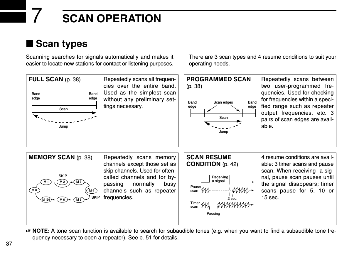
![387SCAN OPERATION7■Scan start/stopDPreparationScan resume condition (p. 42); program the scan edges(pgs. 39, 40); program 2 or more memory channels (pgs. 25,26); set skip settings, if desired (p. 41).DOperationqSelect VFO mode for full/programmed scan with [V/MHz ]; or memory mode for memory scan with[M/CALL ].• Select the desired bank with [BANK ] for bank scan.wSet the squelch to the point where noise is just muted.ePush [V/MHz ] for 1 sec. to start the scan.• To change the scanning direction, rotate [DIAL].• The memory channel readout blinks the scan type as follows:rPush [SET ] to switch full and programmed scan(P1, P2 and P3).tTo stop the scan, push [SET ] or [V/MHz ].zPush [VFO/LOCK] to select VFO mode forfull/programmed scan; push [MR/CALL] to se-lect memory mode for memory scan.• Push [BANK/OPTION] to select a bank for bankscan.xSet the squelch to the point where noise is justmuted.cPush [SCAN2(T-SCAN)] to start the scan.• Push [YY]or [ZZ]for 1 sec. also starts the scan.vPush [SETB(D-OFF)] to switch full and pro-grammed scan (P1, P2 and P3).bTo stop the scan push [SCAN2(T-SCAN)] or[CLRA(MW)].SCAN2SETBSCANLOCKLOCKSCANOPTPRIOSCANLOCKSETANMMONIDUPLOWT-SCANTONEPRIOM/CALLSCANV/MHzDIGITAL PRIO AO BUSYMUTENARMIDLOWLOCKSETANMMONIDUPLOWT-SCANTONEPRIOM/CALLSCANV/MHzDIGITAL PRIO AO BUSYMUTENARMIDLOWLOCKSETANMMONIDUPLOWT-SCANTONEPRIOM/CALLSCANV/MHzDIGITAL PRIO AO BUSYMUTENARMIDLOWLOCKSETANMMONIDUPLOWT-SCANTONEPRIOM/CALLSCANV/MHzDIGITAL PRIO AO BUSYMUTENARMIDLOW• During full scan • During programmed scan • During memory scan • During Bank scanIndicates scan edge channels.• P1 stands for 1A/1b• P1 to P3 are available when they are programmed, and switches with .Push to select full or programmed scan (P1, P2 and P3) in sequence.LOCKSET( )LOCKSET( )](https://usermanual.wiki/ICOM-orporated/269800/User-Guide-381881-Page-49.png)
![397SCAN OPERATION■Scan edges programmingScan edges can be programmed in the same manner asmemory channels. Scan edges are programmed into scanedges, 1A/1b to 3A/3b, in memory channels.qSet the edge frequency of the desired frequency range inVFO mode:➥Set the frequency using [DIAL].➥Set other data (e.g. repeater settings, etc.) if desired.wPush [S.MW ] momentarily.•“M” indicator and channel number blink.eRotate [DIAL] to select one of scan edge channel, 1A, 2Aor 3A.rPush [S.MW ] for 1 sec. to program.• 3 beeps sound and VFO is automatically selected.• Scan edge 1b, 2b or 3b is automatically selected when continu-ing to push [S.MW ] after programming.tTo program a frequency for the other pair of scan edges,1b, 2b or 3b, repeat steps qand r.• If the same frequency is programmed into a pair of scan edges,programmed scan will not function.MWMWMW[EXAMPLE]: Programming 145.300 MHz into scan edges 1A.LOCKSETANMMONIDUPLOWT-SCANTONEPRIOM/CALLSCANV/MHzSCANV/MHzMWS.MWDIGITAL PRIO AO BUSYMUTENARMIDLOWLOCKSETANMMONIDUPLOWT-SCANTONEPRIOM/CALLSCANV/MHzDIGITAL PRIO AO BUSYMUTENARMIDLOWLOCKSETANMMONIDUPLOWT-SCANTONEPRIOM/CALLSCANV/MHzDIGITAL PRIO AO BUSYMUTENARMIDLOWLOCKSETANMMONIDUPLOWT-SCANTONEPRIOM/CALLSCANV/MHzDIGITAL PRIO AO BUSYMUTENARMIDLOWLOCKSETANMMONIDUPLOWT-SCANTONEPRIOM/CALLSCANV/MHzDIGITAL PRIO AO BUSYMUTENARMIDLOWLOCKSETANMMONIDUPLOWT-SCANTONEPRIOM/CALLSCANV/MHzDIGITAL PRIO AO BUSYMUTENARMIDLOWMWS.MW( )Push Rotate for setting frequency, etc. Push momentarily.Rotate Push for 1 sec. and continue to push ➠BeepBeepBeep“““““](https://usermanual.wiki/ICOM-orporated/269800/User-Guide-381881-Page-50.png)
![407SCAN OPERATION7DProgramming scan edges via microphonezSet the desired frequency in VFO mode.➥Push [VFO/LOCK] to select VFO mode.➥Set the frequency via the keypad or [YY]/[ZZ].xPush [FUNC] then [CLRA(MW)] momentarily.cPush [YY]or [ZZ]to select scan edge channels,1A, 2A or 3A.vPush [FUNC], then push [CLRA(MW)] for 1 sec.to program.• 3 beeps sound and VFO is automatically selected.• Memory channel number advances to the next scanedge channel, 1b, 2b or 3b, when continuing to push[CLRA(MW)] after programming.bTo program a frequency for the other scan edge channels,repeat steps zto v.MW[EXAMPLE]: Programming 145.800 MHz into scan edges 1b.LOCKSETANMMONIDUPLOWT-SCANTONEPRIOM/CALLSCANV/MHzDIGITAL PRIO AO BUSYMUTENARMIDLOWLOCKSETANMMONIDUPLOWT-SCANTONEPRIOM/CALLSCANV/MHzDIGITAL PRIO AO BUSYMUTENARMIDLOWLOCKSETANMMONIDUPLOWT-SCANTONEPRIOM/CALLSCANV/MHzDIGITAL PRIO AO BUSYMUTENARMIDLOWLOCKSETANMMONIDUPLOWT-SCANTONEPRIOM/CALLSCANV/MHzDIGITAL PRIO AO BUSYMUTENARMIDLOWLOCKSETANMMONIDUPLOWT-SCANTONEPRIOM/CALLSCANV/MHzDIGITAL PRIO AO BUSYMUTENARMIDLOWLOCKSETANMMONIDUPLOWT-SCANTONEPRIOM/CALLSCANV/MHzDIGITAL PRIO AO BUSYMUTENARMIDLOWBeepBeepBeep“““““Push Push then momentarily.Push Push then 1 sec. and continue to push ➠Push](https://usermanual.wiki/ICOM-orporated/269800/User-Guide-381881-Page-51.png)
![417SCAN OPERATION■Skip channel settingThe memory skip function speeds up scanning by checkingonly those memory channels not set as skip channels. Setskip channels as follows.qSelect a memory channel:➥Push [M/CALL ] to select memory mode.➥Rotate [DIAL] to select the desired channel to be a skipchannel.wPush [SET ] to enter set mode.ePush [SET] or [MONI] several times until “CHS” appearsas shown above.rRotate [DIAL] to turn the skip function ON or OFF for theselected channel.•“~” appears : The channel is skipped during scan. (CHS-ON)•“~” disappears : The channel is scanned during scan.(CHS-OFF)tPush any other key than [SET] or [MONI] to exit set mode.zSelect a memory channel.➥Select memory mode by pushing [MR/CALL].➥Push [YY]or [ZZ]to select the desired channelto be a skip channel.xPush [SETB(D-OFF)] to enter set mode.cPush [SETB(D-OFF)] or [ENTC(T-OFF)] severaltimes until “CHS” appears as shown at left.vPush [YY]or [ZZ]to set or cancel the skip setting.• See item rat left for skip indicator details.bPush [CLRA(MW)] to exit set mode.☞NOTES:Even though scan edge channels cannot be set as skipchannels, they ARE skipped during memory scan.SET mode cannot be accessed when memory names aredisplayed. To set the scan resume condition, return to fre-quency indication by pushing [MONI ] on the frontpanel for 1 sec., or push [FUNC] then [MONI1(ANM)] (HM-133V) to cancel the channel name indication, then set asdescribed on this page.ANMSETBLOCKPRIOLOCKSETANMMONIDUPLOWT-SCANTONEPRIOM/CALLSCANV/MHzDIGITAL PRIO AO BUSYMUTENARMIDLOWThe display shows that memory channel 1 is set as a skip channel.USINGSET MODE](https://usermanual.wiki/ICOM-orporated/269800/User-Guide-381881-Page-52.png)
![427SCAN OPERATION7■Scan resume conditionThe scan resume condition can be selected as timer or pausescan. The selected resume condition is also used for prioritywatch. (p. 44)qPush [SET ] to enter set mode.wPush [SET] or [MONI] several times until “SCT” or “SCP”appears as shown above.• When “d” is displayed in place of the 100 MHz digit, cancel theDTMF memory encoder in advance. (p. 46)eRotate [DIAL] to set the desired timer:• “SCT-15” : Scan pauses 15 sec. while receiving a signal.• “SCT-10” : Scan pauses 10 sec. while receiving a signal.• “SCT-5” : Scan pauses 5 sec. while receiving a signal.• “SCP-2” : Scan pauses until the signal disappears and thenresumes 2 sec. later.rPush any keys than [SET] or [MONI] to exit set mode.zPush [SETB(D-OFF)] to enter set mode.xPush [SETB(D-OFF)] or [ENTC(T-OFF)] severaltimes until “SCT” or “SCP” appears as shown atleft.cPush [YY]or [ZZ]to select the scan resume condi-tion.• See item eat left for scan resume condition details.vPush [CLRA(MW)] to exit set mode.☞NOTE: Set mode cannot be accessed when memory names aredisplayed. To set the scan resume condition, return to fre-quency indication by pushing [MONI ] on the frontpanel for 1 sec., or push [FUNC] then [MONI1(ANM)] (HM-133V) to cancel the channel name indication, then set asdescribed on this page.ANMSETBLOCKLOCKSETANMMONIDUPLOWT-SCANTONEPRIOM/CALLSCANV/MHzDIGITAL PRIO AO BUSYMUTENARMIDLOWThe display shows that the scan will resume 15 sec. after it stops.USINGSET MODE](https://usermanual.wiki/ICOM-orporated/269800/User-Guide-381881-Page-53.png)
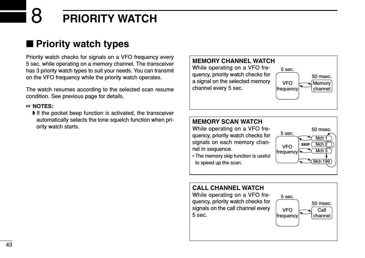
![448PRIORITY WATCH8■Priority watch operationqSelect VFO mode; then, set an operating frequency.wSet the watching channel(s).For memory channel watch:Select the desired memory channel.For memory scan watch:Select memory mode; then, push [V/MHz ] for1 sec. to start memory scan.For call channel watch:Select the call channel by pushing [M/CALL ] onceor twice.ePush [M/CALL ] for 1 sec. to start the watch.• The transceiver checks the memory or call channel every 5 sec.• The watch resumes according to the selected scan resume con-dition. (p. 42)• While the watch is pausing, pushing [M/CALL ] resumesthe watch manually.rPush [M/CALL ] to stop the watch.zSelect VFO mode; then, set an operating fre-quency.xSet the watching channel(s).For memory channel watch:Push [MR/CALL] then [YY]or [ZZ]to select thedesired memory channel.For memory scan watch:Push [MR/CALL], then push [SCAN2] to start thememory scan.For call channel watch:Push [MR/CALL] for 1 sec. to select the callchannel.cPush [PRIO3(PTT-M)] to start the watch.• The transceiver checks the memory or call channelevery 5 sec.• The watch resumes according to the selected scan re-sume condition. (p. 42)• To resume the watch manually when paused, push[PRIO3(PTT-M)] or [CLRA(MW)].vTo stop the watch, push [CLRA(MW)].PRIO3LOCKSETANMMONIDUPLOWT-SCANTONEPRIOM/CALLSCANV/MHzDIGITAL PRIO AO BUSYMUTENARMIDLOWWhile pausing or receiving a signal on the memory or call channel, “PRIO” blinks.PRIOPRIOPRIOPRIOSCAN](https://usermanual.wiki/ICOM-orporated/269800/User-Guide-381881-Page-55.png)
![45DTMF MEMORY ENCODER9■Programming a DTMF codeDTMF codes are used for autopatching, controlling otherequipment, etc. The transceiver has 10 DTMF memory chan-nels (d0–d9) for storage of often-used DTMF codes of up to24 digits.qPush [BANK ] for 1 sec. to enter the DTMF setting.wRotate [DIAL] to turn the DTMF encoder ON.ePush [SET] or [MONI] to enter the DTMF programmingcondition.• Push [V/MHz] to return to the DTMF setting.rRotate [DIAL] to select the desired DTMF memory chan-nel.• The DTMF memory channel indication blinks.tPush [SET] or [MONI].• The first digit blinks.yRotate [DIAL] to select the desired code.uPush [MONI] to select the next digit.• Push [SET] to move the cursor backward.iRepeat the steps yand uto set the desired DTMF tonesequence.• The S/RF indicator shows the digit group. The indication in-creases every 6 digit.oPush [V/MHz], then push any other key than [SET],[MONI] or [V/MHz] to exit DTMF memory programmingcondition.OPT[EXAMPLE]: Programming “5428AB453” into DTMF memory channel “d4.”LOCKSETANMMONIDUPLOWT-SCANTONEPRIOM/CALLSCANV/MHzDIGITAL PRIO AO BUSYMUTENARMIDLOWLOCKSETANMMONIDUPLOWT-SCANTONEPRIOM/CALLSCANV/MHzDIGITAL PRIO AO BUSYMUTENARMIDLOWLOCKSETANMMONIDUPLOWT-SCANTONEPRIOM/CALLSCANV/MHzDIGITAL PRIO AO BUSYMUTENARMIDLOWLOCKSETANMMONIDUPLOWT-SCANTONEPRIOM/CALLSCANV/MHzDIGITAL PRIO AO BUSYMUTENARMIDLOWLOCKSETANMMONIDUPLOWT-SCANTONEPRIOM/CALLSCANV/MHzDIGITAL PRIO AO BUSYMUTENARMIDLOWLOCKSETANMMONIDUPLOWT-SCANTONEPRIOM/CALLSCANV/MHzDIGITAL PRIO AO BUSYMUTENARMIDLOWLOCKSETANMMONIDUPLOWT-SCANTONEPRIOM/CALLSCANV/MHzDIGITAL PRIO AO BUSYMUTENARMIDLOWOPTBANK SET( ) SET( )Push or .V/MHz( )Push , then any other keys than indicated function keys.SET( )Push then rotate .Repeat the previous step until the desired code is entered.Rotate to turn the DTMF encoder ON.Rotate .Push for 1 sec.](https://usermanual.wiki/ICOM-orporated/269800/User-Guide-381881-Page-56.png)
![469DTMF MEMORY ENCODER9■Transmitting a DTMF codeDAutomatic transmission (DTMF memory)zPush [FUNC] then [LOW6(DTMF)] to turn theDTMF memory encoder ON.• “d” appears in place of the 100 MHz digit.xPush [BANK/OPTION] for 1 sec. then [SETB(D-OFF)] to enter the DTMF memory pro-gramming condition.cPush [YY]or [ZZ]to select the desired channel.vPush [PTT] to transmit the selected memory.• Exit the programming condition automatically.• Each push of [PTT] transmits the DTMF code.bPush [FUNC] then [SETB(D-OFF)] to cancel theDTMF memory encoder.• When the DTMF encoder is turned ON continuously,each push of the PTT transmits the previously se-lected DTMF code.DTransmitting a DTMF memory directlyzPush [FUNC] then [LOW6(DTMF)] to turn theDTMF memory encoder ON.• “d” appears in place of the 100 MHz digit.xPush [DTMF-S] to turn the DTMF memory di-rect selection ON.• The function indicator (microphone) lights green.cPush the desired DTMF channel number.• “0” to “9” are available for channel numbers.• The selected DTMF code is automatically transmit-ted without pushing PTT.DTransmitting a DTMF memory directly— continuedNOTE: When no DTMF code programmedchannel number is pushed, it transmits previ-ously transmitted DTMF memory code.vPush [DTMF-S] again to deactivate the DTMFmemory direct selection.bPush [FUNC] then [SETB(D-OFF)] to cancelthe DTMF memory encoder.DManual transmissionzDeactivate the DTMF memory encoder bypushing [FUNC] then [SETB(D-OFF)].xPush [DTMF-S] to turn the DTMF direct selec-tion ON.• The function indicator (microphone) lights green.cPush one of “A” to “F” keys momentarily, thenpush the desired DTMF keys, 0–9 and A to F.• A: [CLRA(MW)] B: [SETB(D-OFF)], C: [ENTC(T-OFF)] D: [SQLYYD(MUTE)], E: [MM(TONE-1)] F: [SQLZZ#(16KEY-L)]• Automatically transmits without pushing PTT.• The first code, one of “A” to “F,” is not transmitted.DTMF code transmission starts from the 2nd code.vPush [DTMF-S] again to deactivate the DTMFdirect selection.DTMF-SDTMF-SDTMF-SDTMF](https://usermanual.wiki/ICOM-orporated/269800/User-Guide-381881-Page-57.png)
![479DTMF MEMORY ENCODER■DTMF speedThe rate at which DTMF memories send individual DTMFcharacters can be set to accommodate operating needs.qPush [PWR] for 1 sec. to turn power OFF.wWhile pushing [SET ], push [PWR] for 1 sec. toturn power ON and enter initial set mode.ePush [SET] or [MONI] several times until “DTD” appearsas shown above.rRotate [DIAL] to select the desired speed as shown in thetable below.tPush [PWR] to exit initial set mode.cps=characters/secLOCKLOCKSETANMMONIDUPLOWT-SCANTONEPRIOM/CALLSCANV/MHzDIGITAL PRIO AO BUSYMUTENARMIDLOWThe display shows the fastest DTMF speed is selected.USINGINITIAL SET MODEDISPLAY INTERVAL SPEEDDTD-- 1 100 msec. 5.0 cpsDTD-- 2 200 msec. 2.5 cpsDTD-- 3 300 msec. 1.6 cpsDTD-- 5 500 msec. 1.0 cps](https://usermanual.wiki/ICOM-orporated/269800/User-Guide-381881-Page-58.png)
![4810POCKET BEEP AND TONE SQUELCH910■Pocket beep operationThis function uses subaudible tones for calling and can beused as a “common pager” to inform you that someone hascalled while you were away from the transceiver.DWaiting for a call from a specific stationqSet the operating frequency.wPush [SET ] to enter set mode.ePush [SET] or [MONI] several times until “Ct” for tonesquelch or “dt” for DTCS squelch appears.rRotate [DIAL] to select the desired tone squelch frequencyor DTCS code.tWhen operating the pocket beep function with DTCSsquelch, push [SET] once then rotate [DIAL] to select theDTCS polarity.yPush any other key than [SET] or [MONI] to exit set mode.uPush [TONE ] several times until “ ” or “ ”are displayed to turn ON the pocket beep with tonesquelch or DTCS squelch, respectively.iWhen a signal with the matched tone is received, thetransceiver emits beep tones and blinks “ ”.• Beep tones sound for 30 sec. and “ ” blinks. To stop the beepsand blinking manually, push any key. When the beep tones arenot stopped manually, “ ” continues flashing until step iis operated.oPush [PTT] to answer.• “ ” disappears and cancels the pocket beep function automati-cally.!0 Push [TONE ] several times until “ ” or “ ” dis-appears to cancel the tone squelch or DTCS squelch func-tion.T-SCANLOCKSETANMMONIDUPLOWT-SCANTONEPRIOM/CALLSCANV/MHzDIGITAL PRIO AO BUSYMUTENARMIDLOWLOCKSETANMMONIDUPLOWT-SCANTONEPRIOM/CALLSCANV/MHzDIGITAL PRIO AO BUSYMUTENARMIDLOWLOCKSETANMMONIDUPLOWT-SCANTONEPRIOM/CALLSCANV/MHzDIGITAL PRIO AO BUSYMUTENARMIDLOWAppears when the pocket beep with tone squelch is activated.Appears when the pocket beepwith DTCS squelch is activated.T-SCANLOCKSETANMMONIDUPLOWT-SCANTONEPRIOM/CALLSCANV/MHzDIGITAL PRIO AO BUSYMUTENARMIDLOWDTCS polarity settingLOCKSETANMMONIDUPLOWT-SCANTONEPRIOM/CALLSCANV/MHzDIGITAL PRIO AO BUSYMUTENARMIDLOWLOCKSETANMMONIDUPLOWT-SCANTONEPRIOM/CALLSCANV/MHzDIGITAL PRIO AO BUSYMUTENARMIDLOWTone squelch frequency setting DTCS code settingLOCK](https://usermanual.wiki/ICOM-orporated/269800/User-Guide-381881-Page-59.png)
![4910 POCKET BEEP AND TONE SQUELCHzSet the operating frequency.xProgram the CTCSS tone frequency or DTCScode in set mode.➥Push [SETB(D-OFF)] to enter set mode.➥Push [SETB(D-OFF)] or [ENTC(T-OFF)]several times until “Ct” for tone squelch or“dt” for DTCS squelch appears.• “ ” blinks when tone squelch (“Ct”), or “ ”blinks when DTCS squelch (“dt”) is selected.➥Push [YY]/[ZZ]to select the desired tonefrequency or DTCS code.➥Push [SETB(D-OFF)] to select “DTP” thenpush [YY]/[ZZ]to select the DTCS polarity.➥Push [CLRA(MW)] to exit set mode.cPush [FUNC] then push [DUP+ 8(TSQLSS)]or [MID5(DTCSSS)] to turn ON the pocketbeep with tone squelch or DTCS squelch, re-spectively.vWhen a signal with the matched tone is re-ceived, the transceiver emits beep tones for30 sec. and blinks “”.bPush [PTT] to answer or push [CLRA(MW)]to stop the beeps and flashing.• “ ” disappears and cancels the pocket beep func-tion automatically.nTo cancel the tone squelch or DTCS squelchfunction, push [FUNC] then [ENTC(T-OFF)]. • “ ” or “ ” disappears DAvailable tone frequency listNOTE: The transceiver has 50 tone frequencies and con-sequently their spacing is narrow compared to units having38 tones. Therefore, some tone frequencies may receiveinterference from adjacent tone frequencies.To prevent interference from adjacent tone frequencies,using the frequencies as in the following table, is recom-mended.DCalling a waiting station using pocket beepA subaudible tone matched with the station’s CTCSS tone fre-quency or 3-digit DTCS code with polarity is necessary. Usethe tone squelch on the next page or a subaudible tone en-coder (pgs. 19, 50)67.069.371.974.488.591.594.897.4114.8118.8123.0127.3151.4156.7162.2167.9203.5210.7218.1225.777.079.782.585.4100.0103.5107.2110.9131.8136.5141.3146.2173.8179.9186.2192.8233.6241.8250.3• Recommended tone frequencies67.069.371.974.477.079.782.585.488.591.594.897.4100.0103.5107.2110.9114.8118.8123.0127.3131.8136.5141.3146.2151.4156.7159.8162.2165.5167.9171.3173.8177.3179.9183.5186.2189.9192.8196.6199.5203.5206.5210.7218.1225.7229.1233.6241.8250.3254.1TSQLSDTCSS](https://usermanual.wiki/ICOM-orporated/269800/User-Guide-381881-Page-60.png)
![5010POCKET BEEP AND TONE SQUELCH10■Tone/DTCS squelch operationThe tone or DTCS squelch opens only when receiving a sig-nal with the same pre-programmed subaudible tone or DTCScode, respectively.qSet the operating frequency.wProgram the CTCSS tone frequency or DTCS code in setmode.• See p. 48 for programming details.ePush [TONE ] several times until “ ” or “ ” ap-pears in the function display.• “ ” for tone squelch; “ ” for DTCS squelch operation.rWhen a signal with the matched tone is received, thesquelch opens and the signal can be heard.• When the received signal includes an unmatched tone, thesquelch does not open. However, the S/RF indicator shows thereceived signal strength.• To open the squelch manually, push [MONI ].tOperate the transceiver in the normal way (push [PTT] totransmit; release [PTT] to receive).yTo cancel the tone squelch, push [TONE ] sev-eral times until “ ” or “ ” disappears.zSet the operating frequency.xProgram the CTCSS tone frequency or DTCScode in set mode.• See p. 49 for programming details.cPush [FUNC] then [SIMP9(TSQL)] or[HIGH4(DTCS)]to turn the tone squelch or DTCSsquelch ON.vWhen a signal with the matched tone is received,the squelch opens and the signal can be heard.• When the received signal includes an unmatchedtone, the squelch does not open. However, the S/RFindicator shows the received signal strength.• To open the squelch manually, push [MONI1(ANM)].bOperate the transceiver in the normal way (push[PTT] to transmit; release [PTT] to receive.nTo cancel the tone squelch, push [FUNC] then[ENTC(T-OFF)].• “ ” or “ ” disappears TSQLDTCST-SCANANMT-SCAN](https://usermanual.wiki/ICOM-orporated/269800/User-Guide-381881-Page-61.png)
![5110 POCKET BEEP AND TONE SQUELCH■Tone scanBy monitoring a signal that is being operated with pocketbeep, tone or DTCS squelch function, you can determine thetone frequency or DTCS code necessary to open a squelch.qSet the channel to be checked for a tone frequency orcode.wPush [TONE ] several times to select the tonecondition or type to be scanned.• One of “ ,” “ ” or “ ” appears ePush [TONE ] for 1 sec. to start the tone scan.• To change the scanning direction, rotate [DIAL].rWhen the CTCSS tone frequency or 3-digit DTCS code ismatched, the squelch opens and the tone frequency istemporarily programmed into the selected condition suchas memory or call channel.• The tone scan pauses when a CTCSS tone frequency or 3-digitDTCS code is detected.• The decoded CTCSS tone frequency or 3-digit DTCS code isused for the tone encoder or tone encoder/decoder dependingon the selected tone condition or type in step w. - No indication : Cannot be used for operation.- “ ” : CTCSS tone encoder- “ ” : CTCSS tone encoder/decoder- “ ” : DTCS tone encoder/decodertPush [V/MHz ] to stop the scan.zSet the channel to be checked for a tone fre-quency.xSelects the tone condition or type to bescanned.• Push [FUNC] then push; [DUP–7(TONE)] for re-peater tone; [SIMP9(TSQL)] for tone squelch;[HIGH4(DTCS)] for DTCS squelch.cPush [FUNC] then [SCAN2(T-SCAN)] to startthe tone scan.vWhen the tone frequency is matched, thesquelch opens and the tone frequency is pro-grammed into the selected mode such asmemory or call channel.bPush [CLRA(MW)] to stop the scan.T-SCANSCANLOCKSETANMMONIDUPLOWT-SCANTONEPRIOM/CALLSCANV/MHzDIGITAL PRIO AO BUSYMUTENARMIDLOWLOCKSETANMMONIDUPLOWT-SCANTONEPRIOM/CALLSCANV/MHzDIGITAL PRIO AO BUSYMUTENARMIDLOWLOCKSETANMMONIDUPLOWT-SCANTONEPRIOM/CALLSCANV/MHzDIGITAL PRIO AO BUSYMUTENARMIDLOWDuring CTCSS tone scan During DTCS code scanT-SCANT-SCAN☞NOTE: The decoded tone frequency is programmed tem-porarily when a memory or call channel is selected. How-ever, this will be cleared when the memory/call channel isre-selected.](https://usermanual.wiki/ICOM-orporated/269800/User-Guide-381881-Page-62.png)
![5812OTHER FUNCTIONS1112■Set mode•Set mode operationqPush [SET ] to enter the set mode.wPush [SET] or [MONI] to select the desired item.eRotate [DIAL] to select the condition or value.rPush any other key than [SET] or [MONI] to exit set mode.•Set mode itemszPush [SETB(D-OFF)] to enter set mode.xPush [SETB(D-OFF)] or [ENTC(T-OFF)] to selectthe desired item.cPush [YY]or [ZZ]to select the condition or value.vPush [CLRA(MW)] to exit set mode.SETBLOCK*Available for USA version only.†Appears when accessing set mode from VFO mode only.‡Appears when accessing set mode from memory mode only.: Push (front panel); or (microphone): Push (front panel); or (microphone)• Weather alert*• AM/FM mode select*• Display dimmer • Display color • Repeater tonefrequency• Tone squelchfrequency • DTCS code • DTCS polarity• Offset frequency• Tuning step• Reverse mode• Scan resume timer• Channel skip setting‡• Bank link function‡• Bank setting‡• Wide/Nar. setting*• Transmit permission](https://usermanual.wiki/ICOM-orporated/269800/User-Guide-381881-Page-63.png)
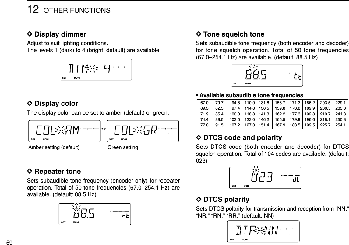
![6012OTHER FUNCTIONS12DDOffset frequencySets the duplex offset frequency within 0 to 20 MHz range.During duplex (repeater) operation, transmit frequency (or re-ceive when reverse function is set to ON) shifts the set fre-quency. (default value may differ depending on versions)DDReverse modeSets the reverse function ON and OFF (default).DDTuning stepSelects tuning step from 5 (default), 10, 12.5, 15, 20, 25, 30and 50 kHz for [DIAL] or [Y]/[Z] operation. DDScan resume timerSelects scan resume timer from SCT-15 (default), SCT-10,SCT-5 and SCP-2. • SCT-15/10/5 : Scan pauses for 15/10/5 sec., then re-sumes.• SCP-2 : Pause on a signal until signal disap-pears, then resumes 2 sec. after the sig-nal disappears.DDTransmit permissionTurns transmission permission ON and OFF. This functioncan be set for each memory, call channel and VFO, indepen-dently.LOCKSETANMMONIDUPLOWT-SCANTONEPRIOM/CALLSCANV/MHzDIGITAL PRIO AO BUSYMUTENARMIDLOWLOCKSETANMMONIDUPLOWT-SCANTONEPRIOM/CALLSCANV/MHzDIGITAL PRIO AO BUSYMUTENARMIDLOWTransmission is permitted. (default)Transmission is inhibited.LOCKSETANMMONIDUPLOWT-SCANTONEPRIOM/CALLSCANV/MHzDIGITAL PRIO AO BUSYMUTENARMIDLOWLOCKSETANMMONIDUPLOWT-SCANTONEPRIOM/CALLSCANV/MHzDIGITAL PRIO AO BUSYMUTENARMIDLOWLOCKSETANMMONIDUPLOWT-SCANTONEPRIOM/CALLSCANV/MHzDIGITAL PRIO AO BUSYMUTENARMIDLOWLOCKSETANMMONIDUPLOWT-SCANTONEPRIOM/CALLSCANV/MHzDIGITAL PRIO AO BUSYMUTENARMIDLOWLOCKSETANMMONIDUPLOWT-SCANTONEPRIOM/CALLSCANV/MHzDIGITAL PRIO AO BUSYMUTENARMIDLOWReverse function OFF (default) Reverse function ONLOCKSETANMMONIDUPLOWT-SCANTONEPRIOM/CALLSCANV/MHzDIGITAL PRIO AO BUSYMUTENARMIDLOW](https://usermanual.wiki/ICOM-orporated/269800/User-Guide-381881-Page-65.png)
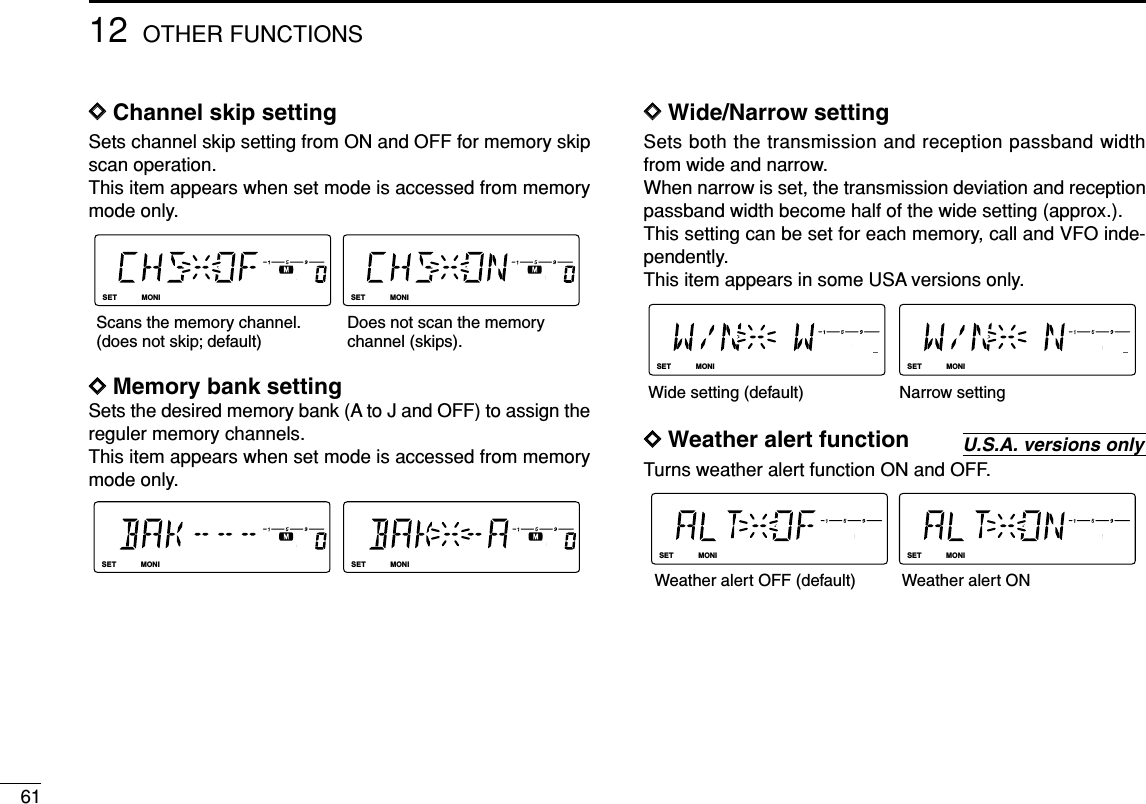
![6212OTHER FUNCTIONS12■Initial set modeThe initial set mode is accessed at power ON and al-lows you to set seldom-changed settings. In this way,you can “customize” transceiver operations to suit yourpreference and operating style.•Initial set mode itemsDDEntering initial set modeqWhile pushing [SET ], push [PWR] for 1 sec. toenter initial set mode.wPush [SET] or [MONI] to select the desired item.eRotate [DIAL] to select the condition or value.rPush [PWR] to exit initial set mode.LOCKATPOWER ONLOCKSETANMMONIDUPLOWT-SCANTONEPRIOM/CALLSCANV/MHzDIGITAL PRIO AO BUSYMUTENARMIDLOWLOCKSETANMMONIDUPLOWT-SCANTONEPRIOM/CALLSCANV/MHzDIGITAL PRIO AO BUSYMUTENARMIDLOWLOCKSETANMMONIDUPLOWT-SCANTONEPRIOM/CALLSCANV/MHzDIGITAL PRIO AO BUSYMUTENARMIDLOWLOCKSETANMMONIDUPLOWT-SCANTONEPRIOM/CALLSCANV/MHzDIGITAL PRIO AO BUSYMUTENARMIDLOWLOCKSETANMMONIDUPLOWT-SCANTONEPRIOM/CALLSCANV/MHzDIGITAL PRIO AO BUSYMUTENARMIDLOWLOCKSETANMMONIDUPLOWT-SCANTONEPRIOM/CALLSCANV/MHzDIGITAL PRIO AO BUSYMUTENARMIDLOWLOCKSETANMMONIDUPLOWT-SCANTONEPRIOM/CALLSCANV/MHzDIGITAL PRIO AO BUSYMUTENARMIDLOWLOCKSETANMMONIDUPLOWT-SCANTONEPRIOM/CALLSCANV/MHzDIGITAL PRIO AO BUSYMUTENARMIDLOWLOCKSETANMMONIDUPLOWT-SCANTONEPRIOM/CALLSCANV/MHzDIGITAL PRIO AO BUSYMUTENARMIDLOWLOCKSETANMMONIDUPLOWT-SCANTONEPRIOM/CALLSCANV/MHzDIGITAL PRIO AO BUSYMUTENARMIDLOWLOCKSETANMMONIDUPLOWT-SCANTONEPRIOM/CALLSCANV/MHzDIGITAL PRIO AO BUSYMUTENARMIDLOW: PushSETLOCK(front panel); or (microphone): Push*Available in USA version only.S.MWMW(front panel); or (microphone)• Key-touch beep• ALC setting• Time-out timer• Auto repeater* • Auto power OFF• Repeater lockout• Squelch delay• S-meter squelch• DTMF speed• Display type• Squelch attenuator](https://usermanual.wiki/ICOM-orporated/269800/User-Guide-381881-Page-67.png)
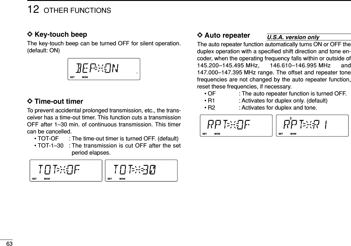
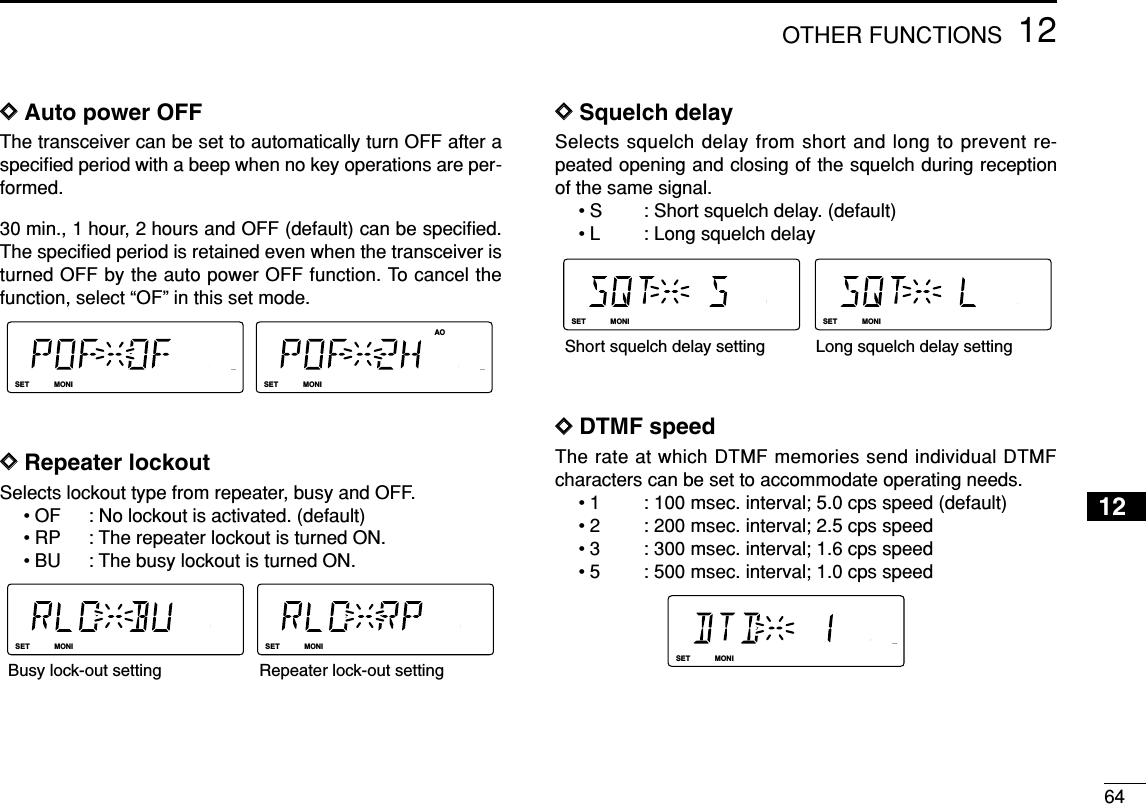
![6512 OTHER FUNCTIONSDDDisplay typeSelects LCD indication type from frequency, channel numberand channel names.• FR : Shows frequency (default)• CH : Shows channel number*• NM : Shows channel names*Programmed memory channels only can be selected.DDSquelch attenuatorTurns the squelch attenuator function ON and OFF.• ON : The squelch attenuator activates when [SQL]control is set between 12 o’clock and fullyclockwise position. (default)• OF : The squelch attenuator does not function.■Weather channel operationDDWeather channel selectionqPush [M/CALL ] sev-eral times to select weatherchannel group. wRotate [DIAL] to select thedesired weather channel. ePush [M/CALL ] toselect memory mode, orpush [V/MHz ] to se-lect VFO mode.SCANPRIOPRIOLOCKSETANMMONIDUPLOWT-SCANTONEPRIOM/CALLSCANV/MHzDIGITAL PRIO AO BUSYMUTENARMIDLOWU.S.A. versions onlyLOCKSETANMMONIDUPLOWT-SCANTONEPRIOM/CALLSCANV/MHzDIGITAL PRIO AO BUSYMUTENARMIDLOWLOCKSETANMMONIDUPLOWT-SCANTONEPRIOM/CALLSCANV/MHzDIGITAL PRIO AO BUSYMUTENARMIDLOWLOCKSETANMMONIDUPLOWT-SCANTONEPRIOM/CALLSCANV/MHzDIGITAL PRIO AO BUSYMUTENARMIDLOWLOCKSETANMMONIDUPLOWT-SCANTONEPRIOM/CALLSCANV/MHzDIGITAL PRIO AO BUSYMUTENARMIDLOWFrequency indication setting Memory channel name indication setting](https://usermanual.wiki/ICOM-orporated/269800/User-Guide-381881-Page-70.png)
![6612OTHER FUNCTIONS12DDWeather alert functionNOAA broadcast stations transmit weather alert tones beforeimportant weather announcements. When the weather alertfunction is turned ON, the selected weather channel is moni-tored each 5 sec. for the announcement. When the alert sig-nal is detected, the “AL.T” and the WX channel are displayedalternately and sounds a beep tone until the transceiver is op-erated. The previously selected (used) weather channel ischecked periodically during standby or while scanning.qSelect the desired weather channel.wTurn the weather alert function ON in set mode.➥Push [SET ] to enter set mode.➥Push [SET ] or [S.MW ] to select theweather alert item, then rotate [DIAL] to set ON.➥Push [TONE ] to exit set mode.eSets the desired stand-by condition.• Selects VFO, memory or call channel.• Scan or priority watch operation can also be selected.rWhen the alert is detected, a beep sounds and the follow-ing indication will be displayed.tTurn the weather alert function OFF in set mode.LOCKSETANMMONIDUPLOWT-SCANTONEPRIOM/CALLSCANV/MHzDIGITAL PRIO AO BUSYMUTENARMIDLOWLOCKSETANMMONIDUPLOWT-SCANTONEPRIOM/CALLSCANV/MHzDIGITAL PRIO AO BUSYMUTENARMIDLOWShows above indications alternately.T-SCANMWLOCKLOCK☞NOTE: While receiving a signal (on a frequency other thanthe weather alert ON frequency), the receiving signal oraudio will be interrupted momentarily every 5 sec. (approx.)in case the alert function is turned ON. This symptom iscaused by the WX alert function. To cancel these symp-toms, set the weather alert item OFF in set mode.](https://usermanual.wiki/ICOM-orporated/269800/User-Guide-381881-Page-71.png)
![6712 OTHER FUNCTIONS■Microphone keysThe supplied HM-133V’s (optional for some versions) [F-1]and [F-2] keys memorize the transceiver conditions. The [UP]/[DN] keys of the standard or an optional micro-phone (other than the HM-133V) can be assigned functionslike the function keys on the transceiver’s front panel.DD[F-1]/[F-2] keys on HM-133VThe following conditions can be memorized into [F-1] and [F-2] keys, independently.• Operating frequency• Repeater setting (offset direction and frequency, toneON/OFF and frequency)• Tone/DTCS squelch (ON/OFF, frequency/code and polarity)• Transmit output power selection• Set mode settings• Initial set mode settings (except display type item)➥Programming the conditionSet the desired contents of each condition,then push [F-1]/[F-2] for 1 sec.• 3 beeps sound.➥Re-calling the conditionPush [F-1]/[F-2] momentarily.DD[UP]/[DN] keys on a microphones(other than HM-133V)The following functions are assigned to the [UP]/[DN] keyson the other microphones (HM-118N/TAN, etc.) when first ap-plying power.[UP] : channel up; push and hold to start scan, push againto stop scan.[DN] : channel down; push and hold to start scan, pushagain to stop scan.➥Assigning a functionqTurn the power OFF.wWhile pushing the desired key on the transceiver and oneof either [UP]/[DN] keys on the microphone, turn thepower ON.• The function is programmed into the key.➥Clearing an assignmentqTurn the power OFF.wWhile pushing the desired [UP] or [DN] key on the micro-phone, turn the power ON.ATPOWER ON[F-1]/[F-2]](https://usermanual.wiki/ICOM-orporated/269800/User-Guide-381881-Page-72.png)
![6812OTHER FUNCTIONS12■Partial resetIf you want to initialize the operating conditions (VFO fre-quency, VFO settings, set mode contents) without clearingthe memory contents, a partial resetting function is availablefor the transceiver.➥Turn power OFF, if transeciver is powered ON.➥While pushing [V/MHz ], turn the power ON to par-tially reset the transceiver.■All resetThe function display may occasionally display erroneous in-formation (e.g. when first applying power). This may becaused externally by static electricity or by other factors.If this problem occurs, turn power OFF. After waiting a fewseconds, turn power ON again. If the problem persists, per-form the following procedure.• Partial resetting is also available. See left for details.IMPORTANT!:Resetting the transceiver CLEARS all memory informationand initializes all values in the transceiver.➥While pushing [SET ] and [S.MW ], turn thepower ON to reset the CPU.LOCKSETANMMONIDUPLOWT-SCANTONEPRIOM/CALLSCANV/MHzDIGITAL PRIO AO BUSYMUTENARMIDLOW[PWR][S.MW MW]MWLOCKATPOWER ONLOCKSETANMMONIDUPLOWT-SCANTONEPRIOM/CALLSCANV/MHzDIGITAL PRIO AO BUSYMUTENARMIDLOW[PWR]SCANATPOWER ON](https://usermanual.wiki/ICOM-orporated/269800/User-Guide-381881-Page-73.png)