ICOM orporated 269800 Amateur Transceiver with Scanning Receiver User Manual
ICOM Incorporated Amateur Transceiver with Scanning Receiver Users Manual
Users Manual

INSTRUCTION MANUAL
i2200H
VHF TRANSCEIVER
This device complies with Part 15 of the FCC rules. Operation is sub-
ject to the following two conditions: (1) This device may not cause
harmful interference, and (2) this device must accept any interference
received, including interference that may cause undesired operation.
i
FOREWORD
Thank you for purchasing this Icom product. The IC-2200H
VHF TRANSCEIVER
is designed and built with Icom’s superior
technology and craftsmanship. With proper care, this product
should provide you with years of trouble-free operation.
We want to take a couple of moments of your time to thank
you for making your IC-2200H your radio of choice, and hope
you agree with Icom’s philosophy of “technology first.” Many
hours of research and development went into the design of
your IC-2200H.
DD
FEATURES
❍65 W* of high transmit output power
(except Taiwan version)
❍Front mounted speaker for clear audio
readability
❍Tone squelch, DTCS squelch standard
❍Dual color (amber & green) LCD backlight
❍Remote control microphone available
(optional for some versions)
❍Optional DTMF decoder
IMPORTANT
READ ALL INSTRUCTIONS carefully and completely
before using the transceiver.
SAVE THIS INSTRUCTION MANUAL— This in-
struction manual contains important operating instructions for
the IC-2200H.
EXPLICIT DEFINITIONS
WORD DEFINITION
RWARNING!
CAUTION
NOTE
Personal injury, fire hazard or electric shock
may occur.
Equipment damage may occur.
Recommended for optimum use. No risk of
personal injury, fire or electric shock.
Icom, Icom Inc. and the logo are registered trademarks of Icom
Incorporated (Japan) in the United States, the United Kingdom, Ger-
many, France, Spain, Russia and/or other countries.

RWARNING RF EXPOSURE! This device emits
Radio Frequency (RF) energy. Extreme caution should be ob-
served when operating this device. If you have any questions re-
garding RF exposure and safety standards please refer to the
Federal Communications Commission Office of Engineering and
Technology’s report on Evaluating Compliance with FCC Guide-
lines for Human Radio frequency Electromagnetic Fields (OET
Bulletin 65)
RWARNING! NEVER connect the transceiver to an AC
outlet. This may pose a fire hazard or result in an electric shock.
RWARNING! NEVER operate the transceiver while dri-
ving a vehicle. Safe driving requires your full attention—anything
less may result in an accident.
NEVER connect the transceiver to a power source of more
than 16 V DC. This will ruin the transceiver.
NEVER connect the transceiver to a power source using re-
verse polarity. This will ruin the transceiver.
NEVER cut the DC power cable between the DC plug and
fuse holder. If an incorrect connection is made after cutting, the
transceiver may be damaged.
NEVER expose the transceiver to rain, snow or any liquids.
The transceiver may be damaged.
NEVER operate or touch the transceiver with wet hands. This
may result in an electric shock or ruin the transceiver.
NEVER place the transceiver where normal operation of the
vehicle may be hindered or where it could cause bodily injury.
NEVER let objects impede the operation of the cooling fan on
the rear panel.
DO NOT
push the PTT when not actually desiring to transmit.
DO NOT allow children to play with any radio equipment con-
taining a transmitter.
During mobile operation, DO NOT operate the transceiver
without running the vehicle’s engine. When the transceiver’s
power is ON and your vehicle’s engine is OFF, the vehicle’s bat-
tery will soon become exhausted.
BE CAREFUL! The transceiver will become hot when op-
erating it continuously for long periods.
AVOID using or placing the transceiver in direct sunlight or in
areas with temperatures below –10°C (+14˚F) or above +60°C
(+140˚F).
AVOID the use of chemical agents such as benzine or alcohol
when cleaning, as they can damage the transceiver’s surfaces.
USE Icom microphones only (supplied or optional). Other man-
ufacturer’s microphones have different pin assignments and may
damage the transceiver if attached.
ii
CAUTIONS
iii
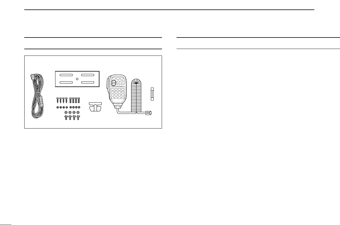
TABLE OF CONTENTSSUPPLIED ACCESSORIES
qDC power cable (3 m) . . . . . . . . . . . . . . . . . . . . . . . . . . . 1
wMobile mounting bracket . . . . . . . . . . . . . . . . . . . . . . . . 1
eMicrophone (HM-133V)* . . . . . . . . . . . . . . . . . . . . . . . . . 1
rFuse (20 A) . . . . . . . . . . . . . . . . . . . . . . . . . . . . . . . . . . . 1
tMounting screws, nuts and washers . . . . . . . . . . . . 1 set
yMicrophone hanger†. . . . . . . . . . . . . . . . . . . . . . . . . . . . 1
*HM-118N
HAND MICROPHONE
or HM-118TN/TAN
DTMF MICROPHONE
supplied versions are also available.
†Depending on version.
qw e
r
ty
FOREWORD ........................................................................................... i
IMPORTANT ............................................................................................ i
EXPLICIT DEFINITIONS ......................................................................... i
CAUTIONS ............................................................................................. ii
SUPPLIED ACCESSORIES .................................................................. iii
TABLE OF CONTENTS ......................................................................... iii
QUICK REFERENCE GUIDE ............................................................ I–VI
■Installation ....................................................................................... I
■Your first contact ........................................................................... IV
■Repeater operation ........................................................................ V
■Programming memory .................................................................. VI
1 PANEL DESCRIPTION ................................................................. 1–8
■Front panel ..................................................................................... 1
■Function display ............................................................................. 3
■Rear panel ..................................................................................... 5
■Microphone (HM-133V) .................................................................. 6
■Microphone keypad ........................................................................ 7
2 SETTING A FREQUENCY .......................................................... 9–12
■Preparation .................................................................................... 9
■Using the tuning dial ...................................................................... 9
■Using the keypad ......................................................................... 10
■Using the [Y]/[Z] keys ................................................................. 10
■Tuning step selection ................................................................... 11
■Lock functions .............................................................................. 12
3 BASIC OPERATION ................................................................. 13–16
■Receiving ..................................................................................... 13
■Monitor function ........................................................................... 13
■Audio mute function ..................................................................... 14
■Squelch attenuator ....................................................................... 14
■Transmitting ................................................................................. 15
■Selecting output power ................................................................ 15
■One-touch PTT function ............................................................... 16

iv
1
2
3
4
5
6
7
8
9
10
11
12
13
14
15
4 REPEATER OPERATION ......................................................... 17–23
■Accessing a repeater ................................................................... 17
■Subaudible tones ......................................................................... 19
■Offset frequency .......................................................................... 21
■Repeater lockout .......................................................................... 21
■Reverse duplex mode .................................................................. 22
■Auto repeater ............................................................................... 23
5 MEMORY OPERATION ............................................................ 24–34
■General description ...................................................................... 24
■Memory channel selection ........................................................... 24
■Programming a memory channel ................................................. 25
■Transferring memory contents ..................................................... 27
■Memory clearing .......................................................................... 29
■Channel names programming ...................................................... 30
■Memory bank selection ................................................................ 32
■Memory bank setting .................................................................... 33
■Transferring bank contents .......................................................... 34
6 CALL CHANNEL OPERATION ................................................ 35–36
■Call channel selection .................................................................. 35
■Call channel transferring .............................................................. 35
■Programming a call channel ........................................................ 36
7 SCAN OPERATION .................................................................. 37–42
■Scan types ................................................................................... 37
■Scan start/stop ............................................................................. 38
■Scan edges programming ............................................................ 39
■Skip channel setting ..................................................................... 41
■Scan resume condition ................................................................ 42
8 PRIORITY WATCH .................................................................... 43–44
■Priority watch types ...................................................................... 43
■Priority watch operation ............................................................... 44
9 DTMF MEMORY ENCODER ..................................................... 45–47
■Programming a DTMF code ......................................................... 45
■Transmitting a DTMF code .......................................................... 46
■DTMF speed ................................................................................ 47
10 POCKET BEEP AND TONE SQUELCH ................................... 48–51
■Pocket beep operation ................................................................. 48
■Tone/DTCS squelch operation ..................................................... 50
■Tone scan ..................................................................................... 51
11 PAGER/CODE SQUELCH ........................................................ 52–57
■Pager function .............................................................................. 52
■Code programming ...................................................................... 52
■Pager operation ........................................................................... 55
■Code squelch ............................................................................... 57
12 OTHER FUNCTIONS ................................................................ 58–70
■Set mode ...................................................................................... 58
■Initial set mode ............................................................................. 62
■Weather channel operation .......................................................... 65
■Microphone keys .......................................................................... 67
■Partial reset .................................................................................. 68
■All reset ........................................................................................ 68
■Data cloning.................................................................................69
13 MAINTENANCE ........................................................................ 71–73
■Troubleshooting ........................................................................... 71
■Fuse replacement ........................................................................ 72
■Optional unit installation ............................................................... 73
14 SPECIFICATIONS AND OPTIONS ................................................. 74
15 MODE ARRANGEMENT ........................................................... 75–76
I
QUICK REFERENCE GUIDE
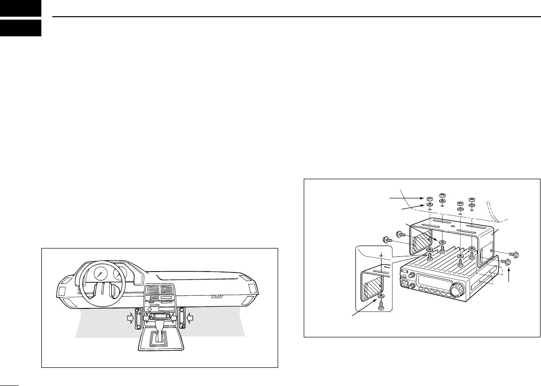
■Installation
DLocation
Select a location which can support the weight of the trans-
ceiver and does not interfere with driving in any way. We rec-
ommend the locations shown in the diagram below.
NEVER place the transceiver where normal operation of the
vehicle may be hindered or where it could cause bodily injury.
NEVER place the transceiver where air bag deployment may
be obstructed.
DO NOT place the transceiver where hot or cold air blows di-
rectly onto it.
AVOID placing the transceiver in direct sunlight.
DUsing the mounting bracket
➀Drill 4 holes where the mounting bracket is to be installed.
• Approx. 5.5–6 mm (1⁄4″) when using nuts; approx. 2–3 mm (1⁄8″)
when using self-tapping screws.
➁Insert the supplied screws, nuts and washers through the
mounting bracket and tighten.
➂Adjust the angle for the clearest view of the function dis-
play.
Nut
Spring washer
Flat washer
When using
self-tapping
screws
Spring
washer
Mounting
nut
Mounting
bracket
II
QUICK REFERENCE GUIDE
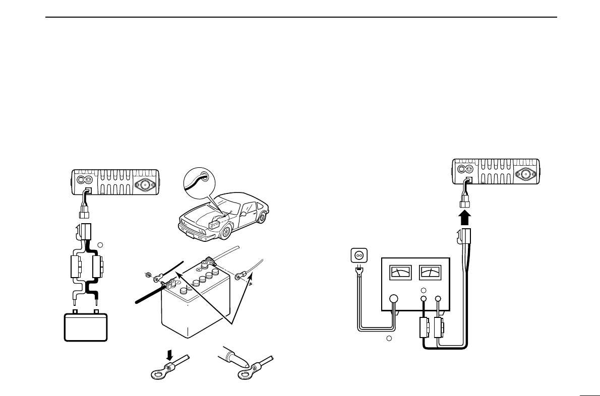
DBattery connection
☞NEVER connect the transceiver directly to a 24 V battery.
☞DO NOT use the cigarette lighter socket for power con-
nections. (See p. 5 for details)
Attach a rubber grommet when passing the DC power cable
through a metal plate to prevent short circuiting.
• CONNECTING TO A DC POWER SOURCE
• See p. 72 for fuse replacement.
DDC power supply connection
Use a 13.8 V DC power supply with at least 15 A capacity.
Make sure the ground terminal of the DC power supply is
grounded.
• CONNECTING TO A DC POWER SUPPLY
• See p. 72 for fuse replacement.
DC power
supply 13.8 V
to an
AC
outlet
Fuses
20 A
black
red⊕
−
⊕
−
IC-2200H
Fuses
20 A
Crimp Solder
black
red⊕
Grommet
IC-2200H
−
12 V
12 V
battery
Supplied
DC power cable
NOTE:
Use terminals for the
cable connections.
+ red
_ black
III
QUICK REFERENCE GUIDE
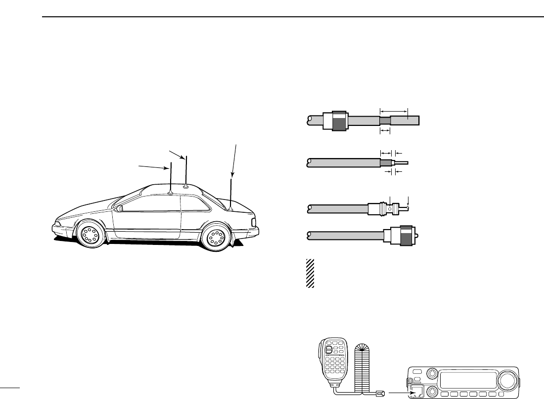
DAntenna installation
•Antenna location
To obtain maximum performance from the transceiver, select
a high-quality antenna and mount it in a good location. A non-
radial antenna should be used when using a magnetic mount.
•Antenna connector
The antenna uses a PL-259 connector.
• PL-259 CONNECTOR
qSlide the coupling ring
down. Strip the cable
jacket and soft solder.
wStrip the cable as shown
at left. Soft solder the cen-
ter conductor.
eSlide the connector body
on and solder it.
rScrew the coupling ring
onto the connector body.
(10 mm ≈3⁄8 in)
NOTE: There are many publications covering proper an-
tennas and their installation. Check with your local dealer
for more information and recommendations.
DConnecting a microphone
Connect a microphone to the eight-pin modular socket on the
front panel of the transceiver.
*HM-133V; A different microphone may be
supplied with some versions of the IC-2200H.
30 mm
10 mm (soft solder)
10 mm
1–2 mm
solder solder
Soft
solder
Coupling ring
Roof-mount antenna
(Drill a hole or use a magnetic mount.)
Gutter-mount antenna
Trunk-mount
antenna
IV
QUICK REFERENCE GUIDE
■Your first contact
Now that you have your IC-2200H installed in your car or
shack, you are probably excited to get on the air. We would
like to take you through a few basic operation steps to make
your first “On The Air” an enjoyable experience.
1. Turning ON the transceiver
Before powering up your IC-2200H, you may want to make
sure the audio volume and squelch level controls are set in
9–10 o’clock positions.
Although you have purchased a brand new transceiver, some
settings may be changed from the factory defaults because
of the QC process. Resetting the CPU is necessary to start
from factory default.
➥While pushing [SET ] and [S.MW ], push
[PWR] for 1 sec. to reset the CPU.
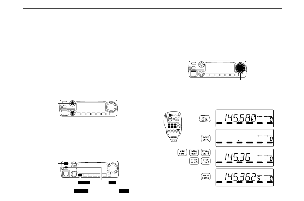
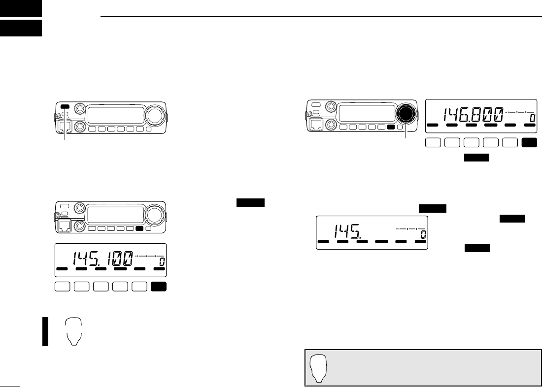
2. Tune the desired frequency
[DIAL] will allow you to dial in the frequency you want to op-
erate. Pages 9 and 11 will instruct you on how to set the tun-
ing speed.
Using the HM-133V
You can directly enter the frequency with the HM-133V keypad.
We hope these pointers have been helpful. Now you
are ready to call CQ.
LOCK
S
E
T
ANM
MONI
DUP
LOW
T-SCAN
TONE
PRIO
M/CALL
SCAN
V/MHz
DIGITAL PRIO AO BUSY
MUTE
NAR
MID
LOW
LOCK
S
E
T
ANM
MONI
DUP
LOW
T-SCAN
TONE
PRIO
M/CALL
SCAN
V/MHz
DIGITAL PRIO AO BUSY
MUTE
NAR
MID
LOW
LOCK
S
E
T
ANM
MONI
DUP
LOW
T-SCAN
TONE
PRIO
M/CALL
SCAN
V/MHz
DIGITAL PRIO AO BUSY
MUTE
NAR
MID
LOW
LOCK
S
E
T
ANM
MONI
DUP
LOW
T-SCAN
TONE
PRIO
M/CALL
SCAN
V/MHz
DIGITAL PRIO AO BUSY
MUTE
NAR
MID
LOW
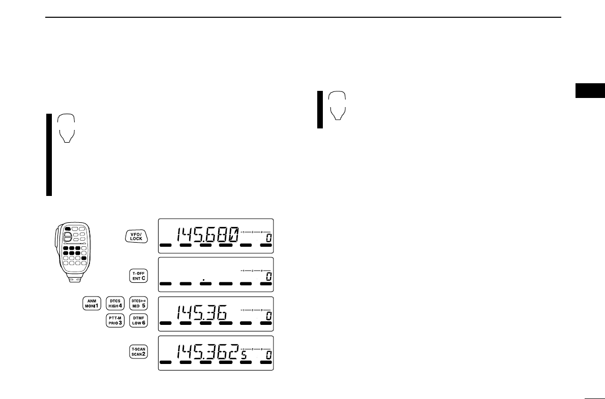
[EXAMPLE]: Setting frequency to 145.3625 MHz.
Push
Push
Push
Push
[DIAL]
MWLOCK
[PWR] [SET LOCK] [S.MW MW]
Set both [VOL] and [SQL] controls to
9–10 o’clock positions.
[VOL]
[SQL]
V
QUICK REFERENCE GUIDE
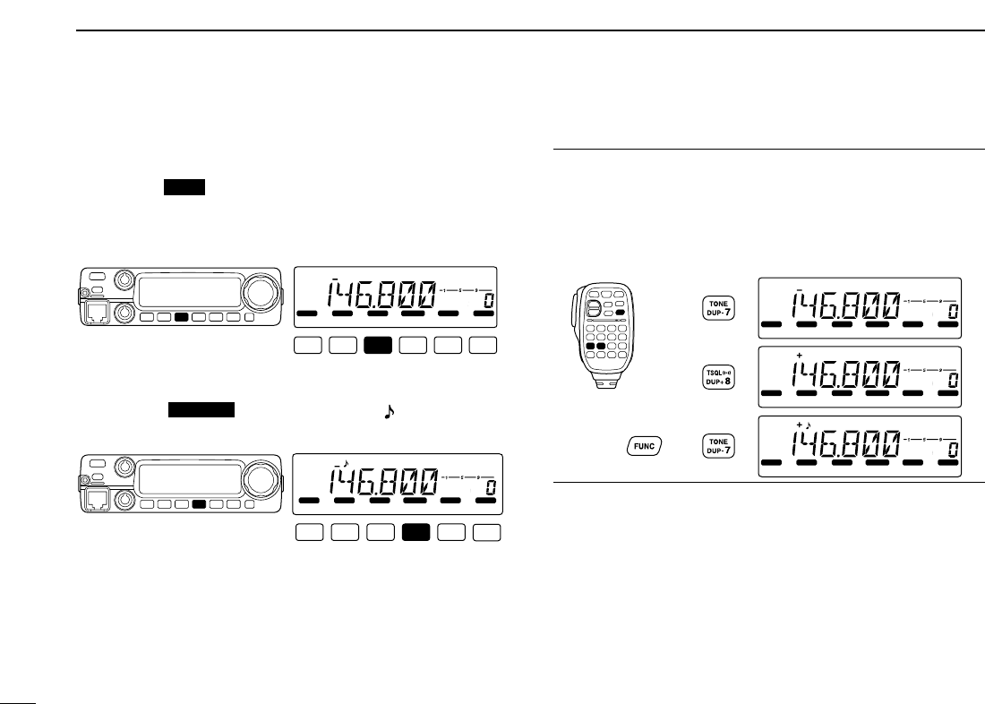
■Repeater operation
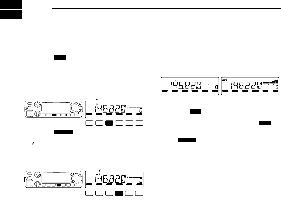
1. Setting duplex
Push [LOW ] for 1 sec. once or twice to select minus
duplex or plus duplex.
• The USA and CSA versions have an auto repeater function, there-
fore, setting duplex is not required.
2. Repeater tone
Push [TONE ] several times until “ ” appears, if the
repeater requires a subaudible to be accessed.
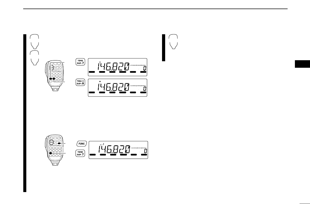
Using the HM-133V
Plus or minus duplex selection and the repeater tone setting
can be made easily via HM-133V.
Push [
DUP
–7(TONE)] for minus duplex; [
DUP
+8(TSQLSS)]
for plus duplex selection, push [FUNC] then [
DUP
–7(TONE)]
to turn the repeater tone ON.
LOCK
S
E
T
ANM
MONI
DUP
LOW
T-SCAN
TONE
PRIO
M/CALL
SCAN
V/MHz
DIGITAL PRIO AO BUSY
MUTE
NAR
MID
LOW
LOCK
S
E
T
ANM
MONI
DUP
LOW
T-SCAN
TONE
PRIO
M/CALL
SCAN
V/MHz
DIGITAL PRIO AO BUSY
MUTE
NAR
MID
LOW
LOCK
S
E
T
ANM
MONI
DUP
LOW
T-SCAN
TONE
PRIO
M/CALL
SCAN
V/MHz
DIGITAL PRIO AO BUSY
MUTE
NAR
MID
LOW
Push
Push , then
Push
LOCK
S
E
T
ANM
MONI
DUP
LOW
T-SCAN
TONE
PRIO
M/CALL
SCAN
V/MHz
DIGITAL PRIO AO BUSY
MUTE
NAR
MID
LOW
T-SCAN
LOCK
S
E
T
ANM
MONI
DUP
LOW
T-SCAN
TONE
PRIO
M/CALL
SCAN
V/MHz
DIGITAL PRIO AO BUSY
MUTE
NAR
MID
LOW
DUP
VI
QUICK REFERENCE GUIDE
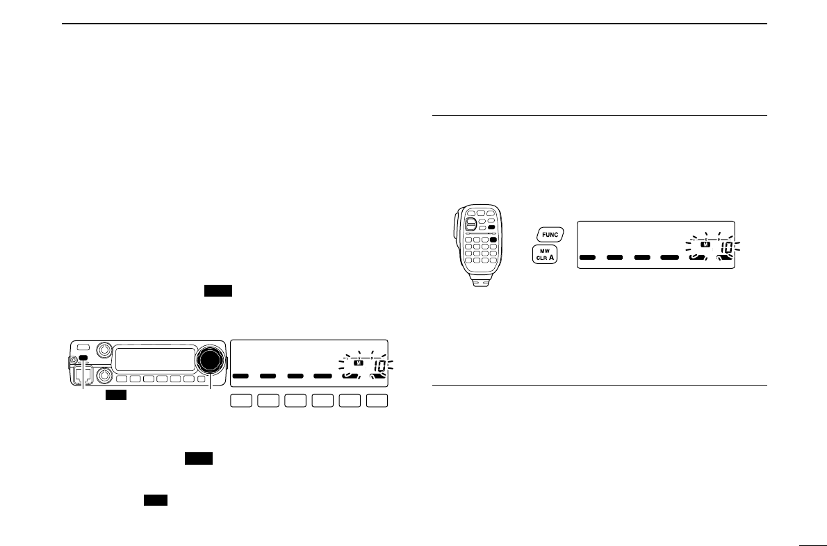
■Programming memory
channels
The IC-2200H has a total of 200 memory channels (including
6 scan edges and 1 call channel) for storing often used oper-
ating frequency, repeater settings, etc.
1. Setting a frequency
In VFO mode, set the desired operating frequency with re-
peater, tone and tuning steps, etc.
2. Selecting a memory channel
Momentarily push [S.MW ], then rotate [DIAL] to select
the desired memory channel.
•“M” indicator and memory channel number blink.
3. Writing a memory channel
Push and hold [S.MW ] for 1 sec. to program.
• 3 beeps sound
• Memory channel number automatically increases when continuing
to push [S.MW ] after programming.
Using the HM-133V
qIn VFO mode, set the desired operating frequency, includ-
ing offset direction, tone settings, etc.
wPush [FUNC] then [
CLR
A(MW)].
•“M” indicator and memory channel number blink.
ePush [YY]/[ZZ]to select the desired memory channel.
rPush [FUNC] then push [
CLR
A(MW)] for 1 sec. to pro-
gram.
• 3 beeps sound
• Memory channel number automatically increases when continu-
ing to push [
CLR
A(MW)] after programming.
LOCK
S
E
T
ANM
MONI
DUP
LOW
T-SCAN
TONE
PRIO
M/CALL
SCAN
V/MHz
DIGITAL PRIO AO BUSY
MUTE
NAR
MID
LOW
Push ,
then
MW
MW
LOCK
S
E
T
ANM
MONI
DUP
LOW
T-SCAN
TONE
PRIO
M/CALL
SCAN
V/MHz
DIGITAL PRIO AO BUSY
MUTE
NAR
MID
LOW
[S.MW MW] [DIAL]
MW
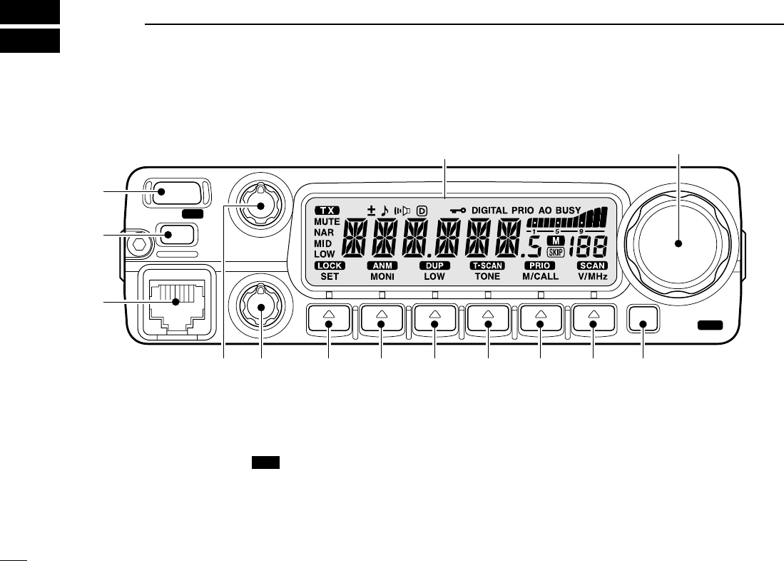
■Front panel
qPOWER KEY [PWR]
Turns power ON and OFF when pushed for 1 sec.
wMEMORY WRITE KEY [S.MW ] (p. 25)
➥Selects a memory channel for programming.
➥Programs the selected memory channel when pushed
for 1 sec.
• Continue to hold the key to increment the memory channel
automatically.
eMICROPHONE CONNECTOR
Connects the supplied microphone.
rVOLUME CONTROL [VOL]
Adjusts the audio level. (p. 13)
tSQUELCH CONTROL [SQL]
Varies the squelch level. (p. 13)
• The RF attenuator activates and increases the attenuation when
rotated clockwise to the center position and further.
MW
PWR
S.MW
MW
BANK
OPT
Function display (p. 4)
!0oiuy
q
w
e
rt
!3
!1 !2
1
PANEL DESCRIPTION
1
2
1
PANEL DESCRIPTION
1
ySET•LOCK KEY [SET ]
➥Enters set mode when pushed. (p. 58)
➥Keys the lock function ON and OFF when pushed for
1 sec. (p. 12)
uMONITOR•CHANNEL NAME KEY [MONI ]
➥Push to switch the monitor function ON and OFF. (p. 13)
➥In memory and call channel mode, switches the channel
names or number ON and OFF. (p. 30)
iOUTPUT POWER KEY [LOW ]
➥Each push changes the output power selection. (p. 15)
➥Select DUP–, DUP+ and simplex operation when
pushed for 1 sec. (p. 17)
oTONE/TONE SCAN KEY [TONE ]
➥Each push selects a tone function. (pgs. 17, 48)
• Tone encoder, pocket beep, tone squelch or tone function
OFF can be selected.
➥Push for 1 sec. to start/stop the tone scan function.
(p. 51)
!0 MEMORY/CALL•PRIORITY KEY [M/CALL ]
➥Push to select and toggle memory, call and weather
channel* modes. (pgs. 24, 35, 65)
*Weather channels available for USA versions only.
➥Starts priority watch when pushed for 1 sec. (p. 44)
!1 VFO/MHz TUNING•SCAN KEY [V/MHz ]
➥Selects and toggles VFO mode and 1 MHz (or 10 MHz
for some versions) tuning when pushed. (p. 9)
➥Starts scan when pushed for 1 sec. (p. 38)
• Cancels a scan when pushed during scan.
!2 BANK•OPTION KEY [BANK ]
➥Push to select memory bank condition during memory
mode. (p. 32)
➥Push for 1 sec. to select and toggle the pager and code
squelch function when the optional UT-108 is installed.
(p. 52)
!3 TUNING DIAL [DIAL]
Selects the operating frequency (p. 9), memory channel
(p. 24), the setting of the set mode item and the scanning
direction (p. 38).
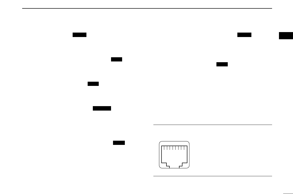
DMicrophone connector (front panel view)
q+8 V DC output (Max. 10 mA)
wChannel up/down
e8 V control IN
rPTT
tGND (microphone ground)
yMIC (microphone input)
uGND
iData IN
qi
OPT
SCAN
PRIO
T-SCAN
DUP
ANM
LOCK
3
1PANEL DESCRIPTION
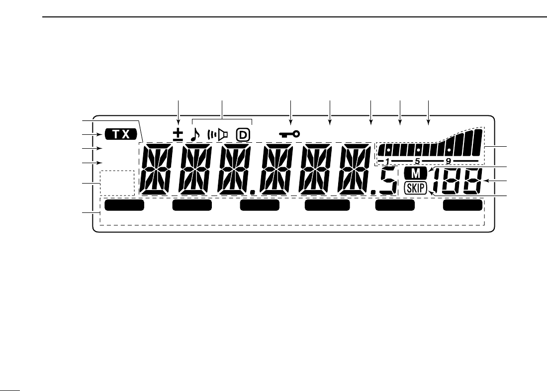
■Function display
qFREQUENCY READOUT
Shows the operating frequency, channel names, set mode
contents, etc.
• Frequency decimal point flashes while scanning. (p. 38)
• “d” appears in place of the 1st digit while the DTMF memory
function is in use. (p. 45)
wTRANSMIT INDICATOR
➥Appears while transmitting. (p. 15)
➥Flashes while transmitting with the one-touch PTT func-
tion. (p. 16)
eAUDIO MUTE INDICATOR (p. 14)
Appears when the audio mute function is activated via mi-
crophone control.
rNARROW MODE INDICATOR (p. 61)
Appears when the narrow mode is selected.
Narrow mode is available with some USA versions only.
tOUTPUT POWER INDICATORS
“LOW” appears when low output power; “LOW” and “MID”
appear when low mid output power; “MID” appears when
middle output power is selected
LOCK
S
E
T
ANM
MONI
DUP
LOW
T-SCAN
TONE
PRIO
M/CALL
SCAN
V/MHz
DIGITAL PRIO AO BUSY
MUTE
NAR
MID
LOW
!7 !3!4
i
!5!6
!0
!2 !1
u
o
w
y
t
e
r
q
4
1
PANEL DESCRIPTION
1
yKEY INDICATORS
Indicate the function(s) of the front panel keys directly
below the function display.
uSKIP INDICATOR (p. 41)
Appears when the displayed memory channel is specified
as a skip channel.
iMEMORY INDICATOR (p. 24)
Appears when memory mode is selected.
oMEMORY CHANNEL NUMBER INDICATORS
➥Shows the selected memory channel number. (p. 24)
➥“C” appears when the call channel is selected. (p. 35)
!0S/RF INDICATORS
➥Shows the relative signal strength while receiving sig-
nals. (p. 13)
➥Shows the output power level while transmitting. (p. 15)
!1BUSY INDICATOR (p. 13)
➥Appears when a signal is being received or the squelch
is open.
➥Flashes while the monitor function is activated.
!2AUTO POWER-OFF INDICATOR (p. 64)
Appears while the auto power-off function is in use.
!3PRIORITY WATCH INDICATOR (p. 44)
Appears while the priority watch is activated; blinks while
the watch is paused.
!4DIGITAL INDICATOR (p. ??)
Appears when digital mode is selected.
!5LOCK INDICATOR (p. 12)
Appears when the lock function is activated.
!6TONE INDICATORS
➥“ ” appears while the subaudible tone encoder is in
use. (p. 17)
➥“ ” appears while the tone (CTCSS) squelch function is
in use. (p. 48)
➥“ ” appears while the tone (DTCS) squelch function is
in use. (p. 48)
➥“ ” appears with the “ ” or “ ” indicator while the
pocket beep function (CTCSS or DTCS) is in use. (p. 48)
!7DUPLEX INDICATORS (p. 17)
“+” appears when plus duplex, “–” appears when minus
duplex operation is selected.
5
1PANEL DESCRIPTION
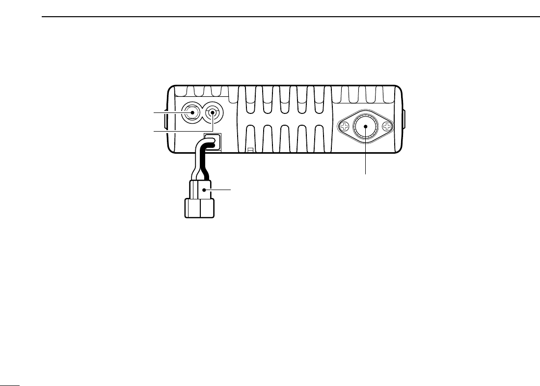
■Rear panel
qSPEAKER JACK [SP]
Accepts an 8 Ωspeaker.
• Audio output power is more than 2.4 W.
wDATA JACK [DATA]
Connects to a PC via an RS-232C cable (D-sub 9-pin) for
remote control in the NMEA or RS-232C format.
ePOWER RECEPTACLE [DC13.8V]
Accepts 13.8 V DC ±15% with the supplied DC power
cable.
☞NOTE: DO NOT use a cigarette lighter socket as a
power source when operating in a vehicle. The plug
may cause voltage drops and ignition noise may be su-
perimposed onto transmit or receive audio.
eCOOLING FAN
Rotates while transmitting.
Also rotates while receiving depending on the setting in set
mode and transceiver’s temperature. (p. 61)
rANTENNA CONNECTOR [ANT]
Connects a 50 Ωantenna with a PL-259 connector and a
50 Ωcoaxial cable.
r
e
q
w
6
1
PANEL DESCRIPTION
1
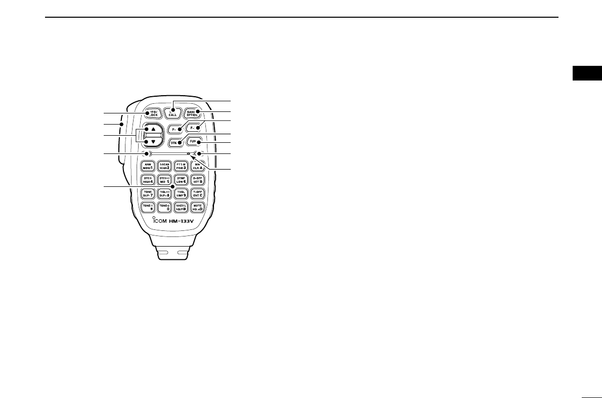
■Microphone (HM-133V*)
qVFO/LOCK KEY [VFO/LOCK]
➥Push to select VFO mode. (p. 9)
➥Push for 1 sec. to switch the lock function ON and OFF.
(p. 12)
wPTT SWITCH
➥Push and hold to transmit; release to receive.
➥Switches between transmitting and receiving while the
one-touch PTT function is in use. (p. 16)
eUP/DOWN KEYS [Y]/[Z]
➥Push either key to change operating frequency, mem-
ory channel, set mode setting, etc. (pgs. 10, 24)
➥Push either key for 1 sec. to start scanning. (p. 38)
rACTIVITY INDICATOR
➥Lights red while any key, except [FUNC] and [DTMF-S],
is pushed, or while transmitting.
➥Lights green while the one-touch PTT function is in use.
tKEYPAD (pgs. 7, 8)
yFUNCTION INDICATOR
➥Lights orange while [FUNC] is activated—indicates the
secondary function of keys can be accessed.
➥Lights green when [DTMF-S] is activated—DTMF sig-
nals can be transmitted with the keypad.
uFUNCTION KEY [FUNC] (pgs. 7, 8)
iDTMF MEMORY SELECT KEY [DTMF-S] (p. 46)
oFUNCTION KEYS [F-1]/[F-2] (p. 67)
Program and re-call your desired transceiver conditions.
!0BANK/OPTION KEY [BANK/OPTION]
➥Push to selects memory bank condition during memory
mode. (p. 32)
➥Push for 1 sec. to select and toggle pager and code
squelch function when the optional UT-108 is installed.
(p. 52)
!1MEMORY/CALL KEY [MR/CALL]
➥Push to select memory mode. (p. 24)
➥Push for 1 sec. to select call channel. (p. 35)
q
e
r
t
Mic element
y
u
i
o
!0
!1
w
*
A different microphone
may be supplied de-
pending on version.
7
1PANEL DESCRIPTION
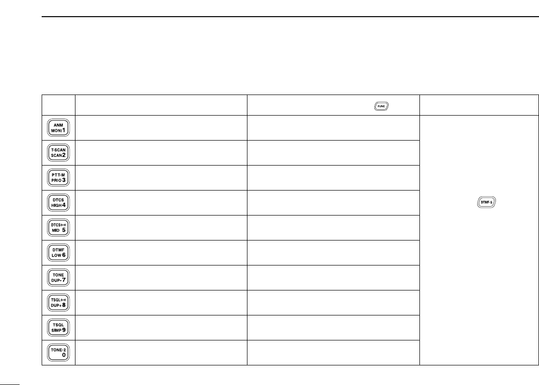
■Microphone keypad
KEY FUNCTION SECONDARY FUNCTION ( +key) OTHER FUNCTIONS
Switches between opening and closing the
squelch. (p. 13)
Starts and stops scanning. (p. 38)
Starts and stops priority watch. (p. 44)
Selects high output power. (p. 15)
Selects mid. output power. (p. 15)
Selects low output power (p. 15)
Selects minus duplex operation. (p. 18)
Selects plus duplex operation. (p. 18)
Selects simplex operation. (p. 18)
No primary function.
In memory mode switches the channel names
or number indication ON and OFF. (p. 31)
Starts and stops tone scanning. (p. 51)
Turns the one-touch PTT function ON and
OFF. (p. 16)
Turns the DTCS squelch ON. (p. 50)
Turns the DTCS pocket beep function ON.
(p. 49)
Turns the DTMF memory encoder function
ON. (p. 45)
Turns the subaudible tone encoder ON.
(p. 18)
Turns the CTCSS pocket beep function
ON. (p. 49)
Turns the tone squelch function ON.
(p. 50)
Sends a 1750 Hz tone signal while pushing
and holding. (p. 20)
After pushing :
Transmits the appropriate
DTMF code. (pgs. 20, 46)
When the DTMF memory en-
coder is activated, push [0] to
[9] to transmit the appropriate
DTMF memory contents .
(p. 46)
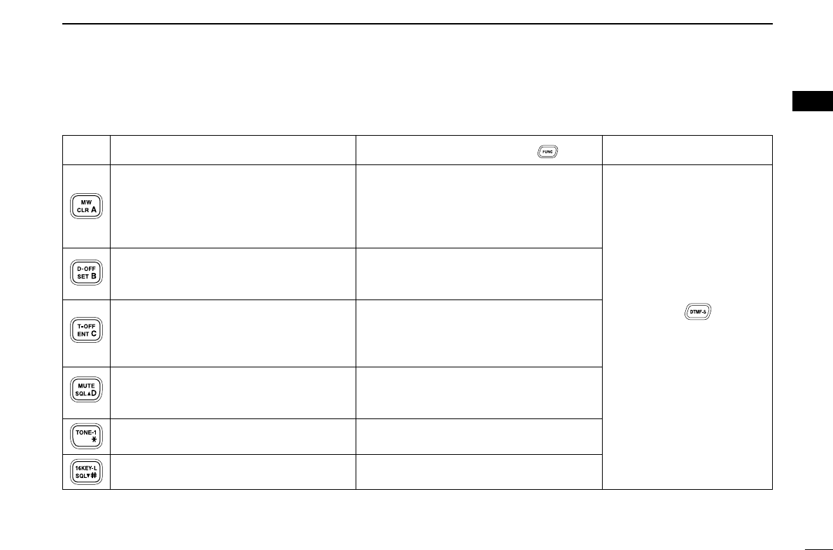
8
1
PANEL DESCRIPTION
1
➥Cancels frequency entry. (p. 10)
➥Cancels the scan or priority watch.
(pgs. 38, 44)
➥Exit set mode. (p. 58)
➥Enters set mode (p. 58)
➥Advances the set mode selection order
after entering set mode. (p. 58)
➥Sets the keypad for numeral input.
(p. 10)
➥Reverses the set mode selection order
after entering set mode. (p. 58)
Adjusts the squelch level increments.
(p. 13)
No primary function.
Adjusts the squelch level decrement.
(p. 13)
➥Selects a memory channel for program-
ming. (p. 26)
➥Advances the memory channel number
when continuously pushed after pro-
gramming is completed. (p. 26)
DTMF memory OFF. (p. 46)
Turns the subaudible tone encoder, pocket
beep or CTCSS/DTCS tone squelch OFF.
(pgs. 18, 49, 50)
Mutes the audio. (p. 14)
• Mute function is released when any oper-
ation is performed.
Sends a 1750 Hz tone signal for 0.5 sec.
(p. 20)
Locks the digit keys on the keypad (includ-
ing the A to D, # and Mkeys. (p. 12)
After pushing :
Transmits the appropriate
DTMF code. (pgs. 20, 46)
KEY FUNCTION SECONDARY FUNCTION ( +key) OTHER FUNCTIONS
9
SETTING A FREQUENCY
2
■Preparation
DTurning power ON/OFF
➥Push [PWR] for 1 sec. to
turn power ON and OFF.
DVFO mode selection
The transceiver has 2 basic operating modes: VFO mode and
memory mode.
➥Push [V/MHz ] to
select VFO mode.
➥Push [VFO/LOCK] to select VFO mode.
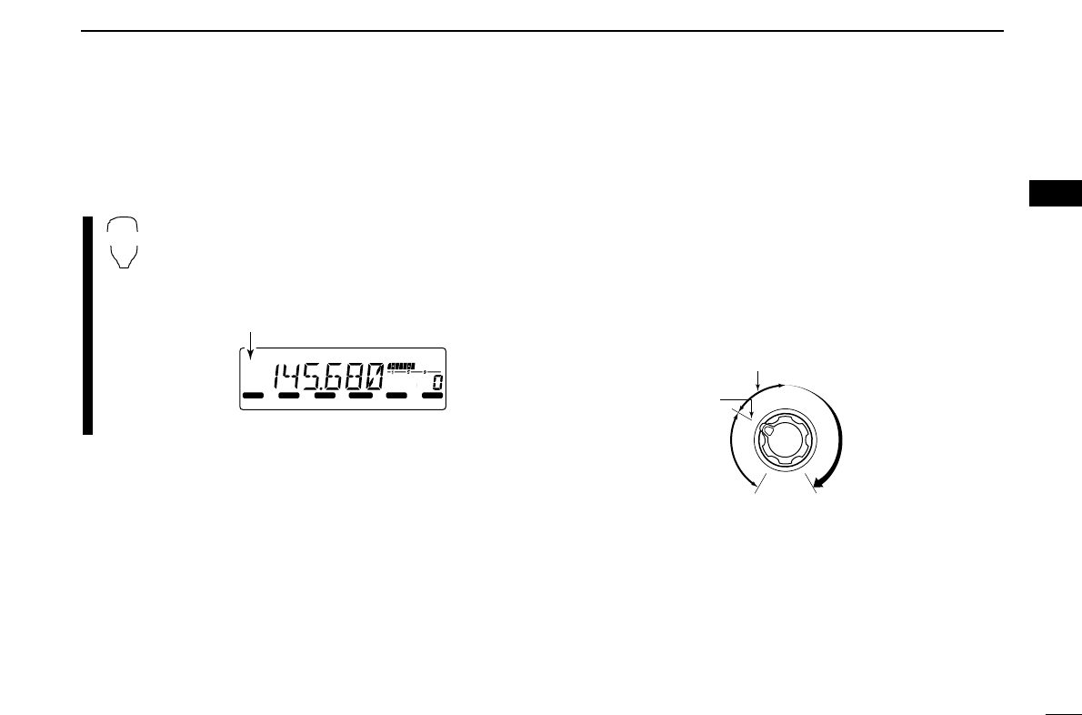
■Using the tuning dial
qRotate [DIAL] to set the frequency.
• If VFO mode is not selected, push [V/MHz ] to select VFO
mode.
• The frequency changes according to the selected tuning steps.
(p. 11)
wTo change the frequency in 1 MHz (10 MHz for some ver-
sions) steps, push [V/MHz ], then rotate [DIAL].
• Pushing [V/MHz ] for
1 sec. starts scan function.
If scan starts, push
[V/MHz ] again to can-
cel it.
SCAN
SCAN
LOCK
S
E
T
ANM
MONI
DUP
LOW
T-SCAN
TONE
PRIO
M/CALL
SCAN
V/MHz
DIGITAL PRIO AO BUSY
MUTE
NAR
MID
LOW
The display shows that the
1 MHz tuning step is selected.
SCAN
SCAN
LOCK
S
E
T
ANM
MONI
DUP
LOW
T-SCAN
TONE
PRIO
M/CALL
SCAN
V/MHz
DIGITAL PRIO AO BUSY
MUTE
NAR
MID
LOW
[DIAL]
VFO/LOCK
SCAN
LOCK
S
E
T
ANM
MONI
DUP
LOW
T-SCAN
TONE
PRIO
M/CALL
SCAN
V/MHz
DIGITAL PRIO AO BUSY
MUTE
NAR
MID
LOW
Push [PWR] for 1 sec.
Note that in this manual, sections beginning with a micro-
phone icon (as above), designate operation via the HM-
133V microphone.
10
2
SETTING A FREQUENCY
2
■Using the keypad
The frequency can be directly set via numeral keys on the mi-
crophone.
zPush [VFO/LOCK] to VFO mode, if necessary.
xPush [
ENT
C(T-OFF)] to activate the keypad for
digit input.
cPush 6 keys to input a frequency.
• When a digit is mistakenly input, push [
ENT
C(T-OFF)]
to clear the input, then repeat input from the 1st digit.
• Pushing [
CLR
A(MW)] clears input digits and retrieves
the frequency.
■Using the [Y]/[Z] keys
➥Push [YY]or [ZZ]to select the desired frequency.
• Pushing [YY]/[ZZ]for 1 sec. activates a scan. If scan
starts, push [YY]/[ZZ]again or push [
CLR
A(MW)] to
cancel it.
YZ
LOCK
S
E
T
ANM
MONI
DUP
LOW
T-SCAN
TONE
PRIO
M/CALL
SCAN
V/MHz
DIGITAL PRIO AO BUSY
MUTE
NAR
MID
LOW
LOCK
S
E
T
ANM
MONI
DUP
LOW
T-SCAN
TONE
PRIO
M/CALL
SCAN
V/MHz
DIGITAL PRIO AO BUSY
MUTE
NAR
MID
LOW
LOCK
S
E
T
ANM
MONI
DUP
LOW
T-SCAN
TONE
PRIO
M/CALL
SCAN
V/MHz
DIGITAL PRIO AO BUSY
MUTE
NAR
MID
LOW
LOCK
S
E
T
ANM
MONI
DUP
LOW
T-SCAN
TONE
PRIO
M/CALL
SCAN
V/MHz
DIGITAL PRIO AO BUSY
MUTE
NAR
MID
LOW
[EXAMPLE]: Setting frequency to 145.3625 MHz.
Push
Push
Push
Push
ENT
C
11
2SETTING A FREQUENCY
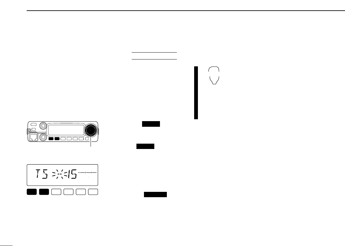
■Tuning step selection
Tuning steps are the minimum frequency change increments
when you rotate [DIAL] or push [YY]/[ZZ]on the microphone.
The following tuning steps are available.
• 5 kHz • 10 kHz • 12.5 kHz • 15 kHz
• 20 kHz • 25 kHz • 30 kHz • 50 kHz
☞NOTE: For convenience, select a tuning step that matches
the frequency intervals of repeaters in your area.
qPush [V/MHz ] to se-
lect VFO mode, if neces-
sary.
wPush [SET ] to enter
set mode.
ePush [SET] or [MONI] sev-
eral times until “TS” appears
as shown at left.
rRotate [DIAL] to select the
desired tuning step.
tPush [TONE ] to
exit set mode.
zPush [VFO/LOCK] to select VFO mode, if
necessary.
xPush [
SET
B(D-OFF)] to enter set mode.
cPush [
SET
B(D-OFF)] or [
ENT
C(T-OFF)]
several times until “TS” appears.
vPush [YY]or [ZZ]to select the desired tun-
ing step.
bPush [
CLR
A(MW)] to exit set mode.
VFO/LOCK
T-SCAN
LOCK
SCAN
LOCK
S
E
T
ANM
MONI
DUP
LOW
T-SCAN
TONE
PRIO
M/CALL
SCAN
V/MHz
DIGITAL PRIO AO BUSY
MUTE
NAR
MID
LOW
15 kHz tuning step
[DIAL]
USING
SET MODE
12
2
SETTING A FREQUENCY
2
■Lock functions
To prevent accidental channel changes and unnecessary
function access, use the lock function. The transceiver has 2
different lock functions.
DFrequency lock
This function locks [DIAL] and keys electronically and can be
used together with the microphone lock function.
➥Push [SET ] for
1 sec. to turn the lock func-
tion ON and OFF.
•[PTT], [MONI ], [VOL]
and [SQL] can be used while
the channel lock function is in
use. Also, TONE-1, TONE-2,
DTMF tones or DTMF mem-
ory contents can be transmit-
ted from the microphone.
➥Push [VFO/LOCK] for 1 sec. to switch the
lock function ON and OFF.
DMicrophone keypad lock
This function locks the microphone keypad.
➥Push [FUNC] then [
SQL
ZZ#(16KEY-L)] to
switch the microphone keypad lock function
ON and OFF.
•[PTT], [VFO/LOCK], [MR/CALL], [BANK/OP-
TION], [YY], [ZZ], [F-1], [F-2], [DTMF-S] and
[FUNC] on the microphone can be used.
• All keys on the transceiver can be used.
• The keypad lock function is released when the
power is turned OFF then ON again.
16KEY-L
VFO/LOCK
ANM
LOCK
LOCK
S
E
T
ANM
MONI
DUP
LOW
T-SCAN
TONE
PRIO
M/CALL
SCAN
V/MHz
DIGITAL PRIO AO BUSY
MUTE
NAR
MID
LOW
Appears
13
BASIC OPERATION
3
■Receiving
qPush [PWR] for 1 sec. to turn power ON.
wSet the audio level.
➥Push [MONI ] to open the squelch.
➥Rotate the [VOL] control to adjust the audio output
level.
➥Push [MONI ] again to close the squelch.
eSet the squelch level.
➥Rotate [SQL] fully counterclockwise in advance.
➥Rotate [SQL] clockwise until the noise just disappears.
➥When interference is received, rotate [SQL] clockwise
again for attenuator operation.
rSet the operating frequency. (pgs. 9, 10)
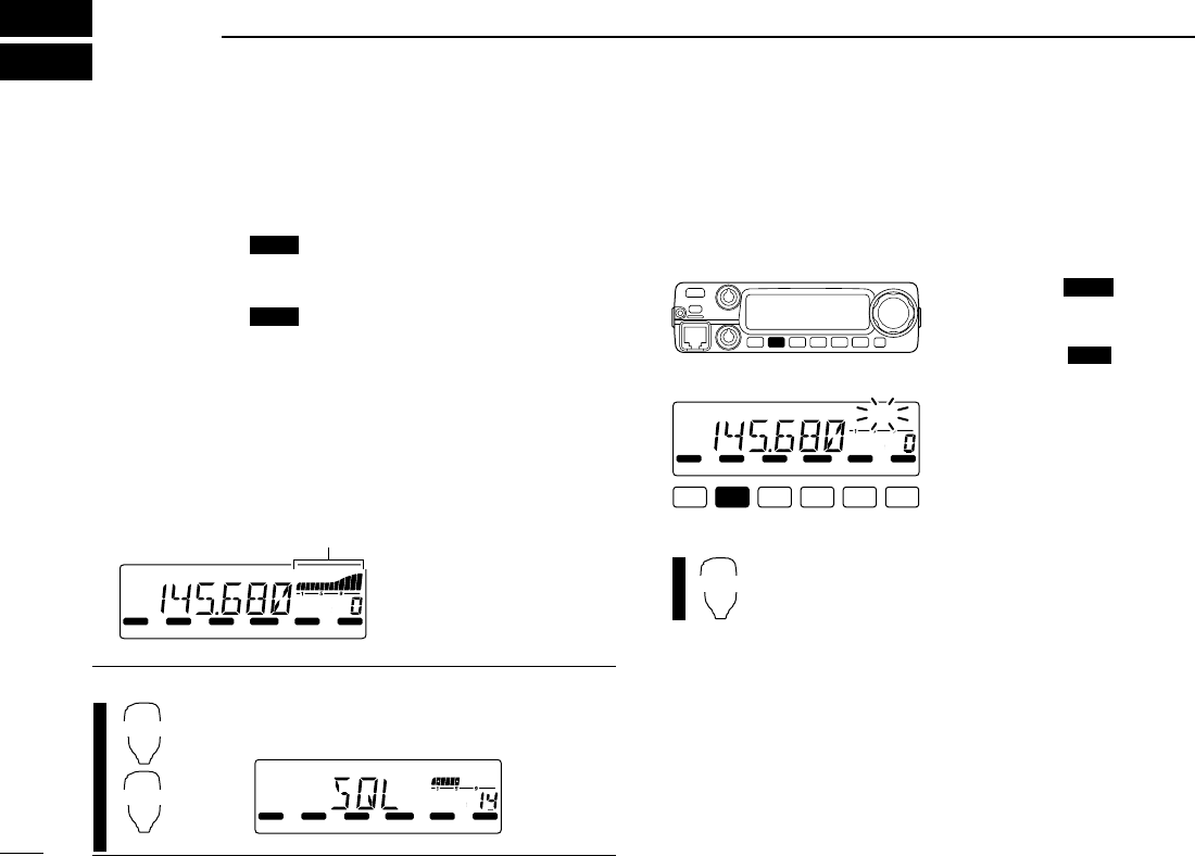
tWhen receiving a signal on the set frequency, squelch
opens and the transceiver emits audio.
• “BUSY” appears and the S/RF
indicator shows the relative
signal strength for the re-
ceived signal.
✔
CONVENIENT!
The squelch level can also be adjusted with
[
SQL
YYD(MUTE)] and [
SQL
ZZ#(16KEY-L)].
■Monitor function
This function is used to listen to weak signals without disturb-
ing the squelch setting or to open the squelch manually even
when mute functions such as the tone squelch are in use.
➥Push [MONI ] to open
the squelch.
• “BUSY” blinks.
• Push [MONI ] again to
cancel the function.
➥Push [
MONI
1(ANM)] to open the squelch.
• Push [
MONI
1(ANM)] again to cancel the function.
MONI
1
ANM
ANM
LOCK
S
E
T
ANM
MONI
DUP
LOW
T-SCAN
TONE
PRIO
M/CALL
SCAN
V/MHz
DIGITAL PRIO AO BUSY
MUTE
NAR
MID
LOW
LOCK
S
E
T
ANM
MONI
DUP
LOW
T-SCAN
TONE
PRIO
M/CALL
SCAN
V/MHz
DIGITAL PRIO AO BUSY
MUTE
NAR
MID
LOW
SQLY
D
SQLZ
#
LOCK
S
E
T
ANM
MONI
DUP
LOW
T-SCAN
TONE
PRIO
M/CALL
SCAN
V/MHz
DIGITAL PRIO AO BUSY
MUTE
NAR
MID
LOW
Appears when receiving a signal.
ANM
ANM
14
3
BASIC OPERATION
3
■Audio mute function
This function temporarily mutes the audio without disturbing
the volume setting.
➥Push [FUNC] then [
SQL
YYD(MUTE)] to mute
audio signals.
• “MUTE” appears.
• Push [
CLR
A(MW)] (or any other key) to cancel the
function.
■Squelch attenuator
The transceiver has an RF attenuator related to the squelch
level setting. Approx. 10 dB attenuation is obtained at maxi-
mum setting.
➥Rotate [SQL] clockwise past the 12 o’clock position to ac-
tivate the squelch attenuator.
• Attenuation level can be adjusted up to 10 dB (approx.) between
12 o’clock and fully clockwise position.
• When setting the squelch from the microphone, a level greater
than ‘19’ activates the squelch attenuator.
Squelch is
open.
Squelch
attenuator
Squelch
threshold
Shallow Deep
Noise squelch
LOCK
S
E
T
ANM
MONI
DUP
LOW
T-SCAN
TONE
PRIO
M/CALL
SCAN
V/MHz
DIGITAL PRIO AO BUSY
MUTE
NAR
MID
LOW
Appears
MUTE
15
3BASIC OPERATION
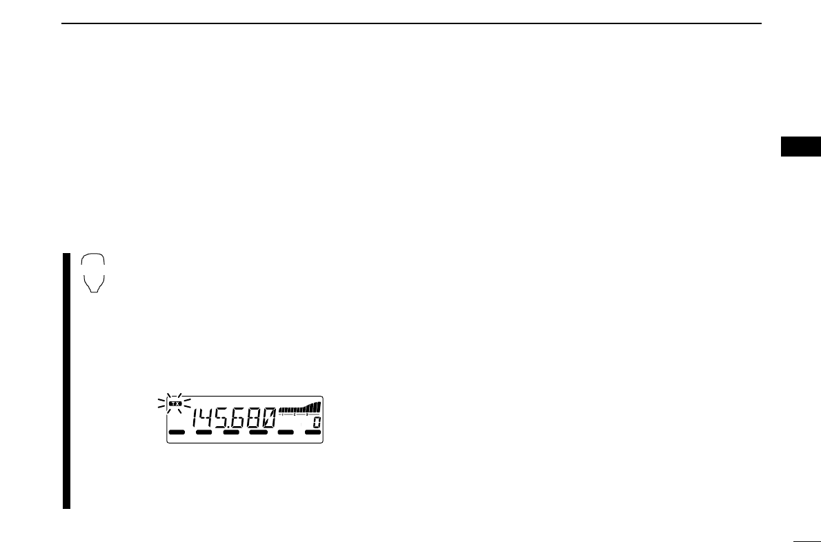
■Transmitting
☞NOTE: To prevent interference, listen on the channel be-
fore transmitting by pushing [MONI ], or
[
MONI
1(ANM)] on the microphone.
qSet the operating frequency. (pgs. 9, 10)
• Select output power if desired. See section at right for details.
wPush and hold [PTT] to transmit.
•“$” appears.
• The S/RF indicator shows the output power selection.
• A one-touch PTT function is available. See p. 16 for details.
eSpeak into the microphone using your normal voice level.
• DO NOT hold the microphone too close to your mouth or speak
too loudly. This may distort the signal.
rRelease [PTT] to return to receive.
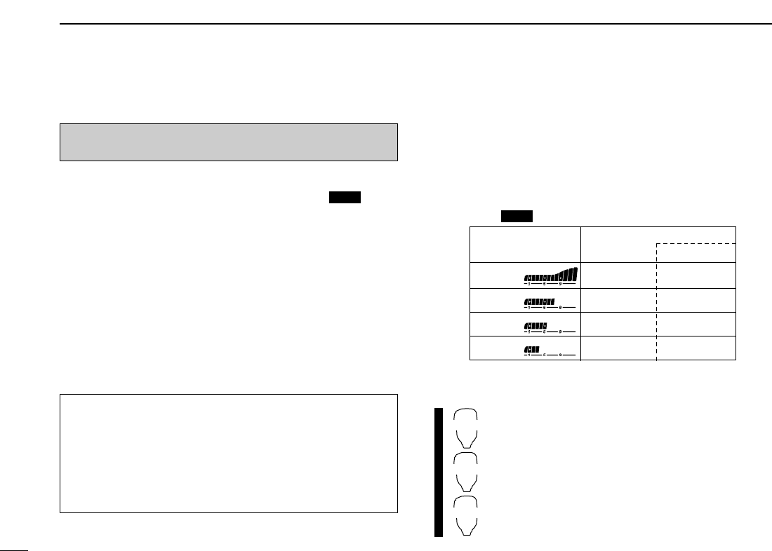
■Selecting output power
The transceiver has 4* output power levels to suit your oper-
ating requirements. Low output powers during short-distance
communications may reduce the possibility of interference to
other stations and will reduce current consumption.
*The Taiwan version has only 3 levels.
Push [LOW ] several times to select the output power.
• The output power can be changed while transmitting. *approx.
The microphone can also be used to select output power.
➥Push [
HIGH
4(DTCS)] for high output power;
[
MID
5(DTCSSS)] for middle output power; and
[
LOW
6(DTMF)] for low output power.
• The output power can be changed via the microphone
during receive only.
HIGH
4
MID
5
LOW
6
DUP
IMPORTANT! (for 65 W transmission):
The IC-2200H is equipped with protection circuit to protect
the power amplifier circuit from high SWR (Standing Wave
Ratio) and temperature. When a high SWR antenna or no
antenna is connected, or when the transceiver temperature
becomes extremely high, the transceiver reduces transmit
output power to 25 W (approx.) automatically.
ANM
CAUTION: Transmitting without an antenna will damage
the transceiver.
S/RF INDICATOR POWER OUTPUT
Taiwan
65 W 24 W
25 W* 10 W*
10 W* N/A
5W* 5W*
High:
Mid.:
Mid. Low:
Low:
16
3
BASIC OPERATION
3
■One-touch PTT function
The PTT switch can be operated as a one-touch PTT switch
(each push switches between transmit/receive). Using this
function you can transmit without pushing and holding the
PTT switch.
To prevent accidental, continuous transmissions with this
function, the transceiver has a time-out timer. See p. 63 for
details.
zPush [FUNC] then [
PRIO
3(PTT-M)] to turn the
one-touch PTT function ON.
• The activity indicator lights green.
xPush [PTT] to transmit and push again to re-
ceive.
• Two beeps sound when transmission is started and a
long beep sounds when returning to receive.
•“$” flashes when transmitting with the one-touch
PTT function.
cPush [FUNC] then [
PRIO
3(PTT-M)] to turn the
one-touch PTT function OFF.
• The activity indicator goes out.
LOCK
S
E
T
ANM
MONI
DUP
LOW
T-SCAN
TONE
PRIO
M/CALL
SCAN
V/MHz
DIGITAL PRIO AO BUSY
MUTE
NAR
MID
LOW
PTT-M
17
REPEATER OPERATION
4
■Accessing a repeater
qSet the receive frequency (repeater output frequency).
(pgs. 9, 10)
wPush [LOW ] for 1 sec., once or twice, to select
minus duplex or plus duplex.
• “–” or “+” appears to indicate the transmit frequency for minus
shift or plus shift, respectively.
• When the auto repeater function is turned ON (available for the
USA and CSA versions), steps wand eare not necessary.
(p. 23)
ePush [TONE ] several times to turn ON the sub-
audible tone encoder, according to repeater requirements.
•
“ ” appears
• 88.5 Hz is set as the default; refer to p. 19 for tone frequency set-
tings.
• When the repeater requires a different tone system, see p. 20.
rPush and hold [PTT] to transmit.
• The displayed frequency automatically changes to the transmit
frequency (repeater input frequency).
• If
“OFF” appears, confirm that the offset frequency (p. 21) is set
correctly.
tRelease [PTT] to receive.
yPush [MONI ] to check whether the other station’s
transmit signal can be received directly.
uTo return to simplex operation, push [LOW ] for
1 sec., once or twice, to clear the “–” or “+” indicator.
iTo turn OFF the subaudible tone encoder, push
[TONE ] several times until no tone indicators ap-
pear.
T-SCAN
DUP
ANM
LOCK
S
E
T
ANM
MONI
DUP
LOW
T-SCAN
TONE
PRIO
M/CALL
SCAN
V/MHz
DIGITAL PRIO AO BUSY
MUTE
NAR
MID
LOW
LOCK
S
E
T
ANM
MONI
DUP
LOW
T-SCAN
TONE
PRIO
M/CALL
SCAN
V/MHz
DIGITAL PRIO AO BUSY
MUTE
NAR
MID
LOW
While transmittingWhile receiving.
LOCK
S
E
T
ANM
MONI
DUP
LOW
T-SCAN
TONE
PRIO
M/CALL
SCAN
V/MHz
DIGITAL PRIO AO BUSY
MUTE
NAR
MID
LOW
Appears
T-SCAN
LOCK
S
E
T
ANM
MONI
DUP
LOW
T-SCAN
TONE
PRIO
M/CALL
SCAN
V/MHz
DIGITAL PRIO AO BUSY
MUTE
NAR
MID
LOW
Either “–” or “+” appears.
DUP
zSet the receive frequency (repeater output fre-
quency). (pgs. 9, 10)
xPush [
DUP
–7(TONE)] to select minus duplex;
push [
DUP
+ 8(TSQLSS)] to select plus duplex.
cPush [FUNC] then [
DUP
–7(TONE)] to turn ON
the subaudible tone encoder according to re-
peater requirements.
• Refer to p. 19 for the tone frequency setting.
• When the repeater requires a different tone system,
see p. 20.
vPush and hold [PTT] to transmit.
bRelease [PTT] to receive.
nPush [
MONI
1(ANM)] to check whether the other
station’s transmit signal can be received directly.
mPush [
SIMP
9(TSQL)] to return to simplex oper-
ation.
• “+” or “–” indicator disappears.
,To turn OFF the subaudible tone encoder, push
[FUNC] then [
ENT
C(T-OFF)].
SIMP
9
LOCK
S
E
T
ANM
MONI
DUP
LOW
T-SCAN
TONE
PRIO
M/CALL
SCAN
V/MHz
DIGITAL PRIO AO BUSY
MUTE
NAR
MID
LOW
Push ,
then .
LOCK
S
E
T
ANM
MONI
DUP
LOW
T-SCAN
TONE
PRIO
M/CALL
SCAN
V/MHz
DIGITAL PRIO AO BUSY
MUTE
NAR
MID
LOW
LOCK
S
E
T
ANM
MONI
DUP
LOW
T-SCAN
TONE
PRIO
M/CALL
SCAN
V/MHz
DIGITAL PRIO AO BUSY
MUTE
NAR
MID
LOW
Push
Push
DUP–
7
DUP+
8
18
4
REPEATER OPERATION
4
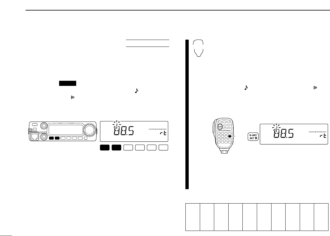
■Subaudible tones
(Encoder function)
DSubaudible tones
qSelect the mode/channel you wish to set the subaudible
tones to, such as VFO mode or memory/call channel.
wPush [SET ] to enter set mode.
e
Push
[SET]
or
[MONI]
several times until “ ”
and “rt” ap-
pears; or until “ ” and “Ct” appears for tone squelch or
pocket beep use.
• When “d” is displayed in place of the 100 MHz digit, cancel the
DTMF memory encoder in advance. (p. 46)
rRotate [DIAL] to select and set the desired subaudible fre-
quency.
tPush any other key than [SET] or [MONI] to exit set mode.
☞NOTE: The subaudible tone encoder frequency can be set
in a memory/call channel temporarily. However, the set fre-
quency is cleared once another memory channel or VFO
mode is selected. To store the tone frequency permanently,
overwrite the channel information.
zSet the mode/channel you wish to set the sub-
audible tones to, such as VFO mode or mem-
ory/call channel.
• The subaudible tone frequency is independently pro-
grammed into each mode or channel.
xPush [
SET
B(D-OFF)] to enter set mode.
c
Push [
SET
B(D-OFF)] or [
ENT
C(T-OFF)] several
times until “ ”
and “rt” appears; or until “ ” and
“Ct” appears for tone squelch or pocket beep
use.
•
When “d” is displayed in place of the 100 MHz digit,
cancel the DTMF memory encoder in advance. (p. 46)
vPush [YY]or [ZZ]to select and set the desired
subaudible tone frequency.
• Push and hold [YY]/[ZZ]to change the above tones
continuously.
bPush [
CLR
A(MW)] to exit set mode.
•Subaudible tone frequency list (unit: Hz)
67.0
69.3
71.9
74.4
77.0
79.7
82.5
85.4
88.5
91.5
94.8
97.4
100.0
103.5
107.2
110.9
114.8
118.8
123.0
127.3
131.8
136.5
141.3
146.2
151.4
156.7
159.8
162.2
165.5
167.9
171.3
173.8
177.3
179.9
183.5
186.2
189.9
192.8
196.6
199.5
203.5
206.5
210.7
218.1
225.7
229.1
233.6
241.8
250.3
254.1
LOCK
S
E
T
ANM
MONI
DUP
LOW
T-SCAN
TONE
PRIO
M/CALL
SCAN
V/MHz
DIGITAL PRIO AO BUSY
MUTE
NAR
MID
LOW
Push
SET
B
LOCK
S
E
T
ANM
MONI
DUP
LOW
T-SCAN
TONE
PRIO
M/CALL
SCAN
V/MHz
DIGITAL PRIO AO BUSY
MUTE
NAR
MID
LOW
LOCK
USING
SET MODE
19
4REPEATER OPERATION
20
4
REPEATER OPERATION
4
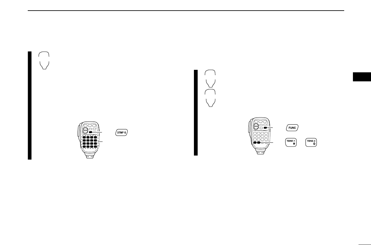
DDTMF tones
➥Push [DTMF-S], then push the keys of the de-
sired DTMF digits.
• The function indicator lights green.
• 0–9, A–D, M(E) and #(F) are available.
• When “d” is displayed in place of the 100 MHz digit,
cancel the DTMF memory encoder in advance.
(p. 46)
• Push [DTMF-S] again to return the keypad to nor-
mal function control.
• The transceiver has 10 DTMF memory channels
for autopatch operation. See p. 45 for details.
D1750 Hz tone
The microphone has 1750 Hz tone capability, used for ring
tone when calling, etc.
zPush [FUNC].
• The function indicator lights orange.
xPush [MM(TONE-1)] to transmit a 1750 Hz tone
call signal for 0.5 sec.; push and hold
[0(TONE-2)] to transmit a 1750 Hz tone call
signal for an arbitrary period.
• The function indicator goes out automatically.
Push ,
then or .
TONE-1
TONE-2
then push desired keys.
Push ,
DTMF-S
■Offset frequency
When communicating thorough a repeater, the transmit fre-
quency is shifted from the receive frequency by an amount
determined by the offset frequency.
qPush [SET ] to enter set mode.
wPush [SET] or [MONI] until “±” and offset frequency ap-
pear.
e
Rotate
[DIAL]
to set the desired offset frequency.
• Push [V/MHz] to select the 1 MHz tuning steps.
rPush [TONE ] to exit set mode.
zPush [
SET
B(D-OFF)] to enter set mode.
x
Push [
SET
B(D-OFF)] or [
ENT
C(T-OFF)] until
“±”
and offset frequency appear.
cPush [YY]or [ZZ]to set the desired
offset.
• Direct frequency entry from the keypad is not possi-
ble.
vPush [
CLR
A(MW)] to exit set mode.
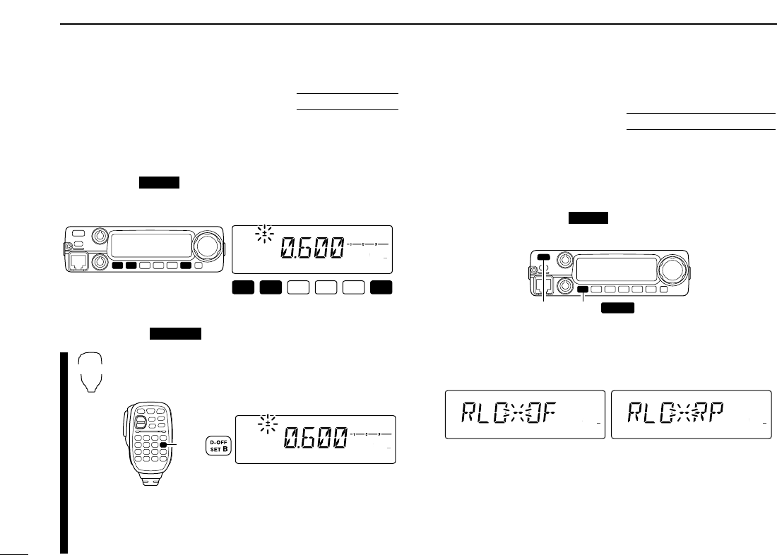
■Repeater lockout
This function helps prevent interference to other stations by
inhibiting your transmission when a signal is received. The
transceiver has two inhibiting conditions, repeater and busy.
qPush [PWR] to turn power OFF.
wWhile pushing [SET ], turn power ON to enter ini-
tial set mode.
ePush [SET] or [MONI] several times until the “RLO” dis-
play appears as shown below.
rRotate [DIAL] to turn the repeater lockout function to “RP,”
“BU” or OFF.
• “RP”: Transmit is inhibited when a signal with un-matched sub-
audible tone is received.
• “BU”: Transmit is inhibited when a signal is received.
tPush [PWR] to exit initial set mode.
LOCK
S
E
T
ANM
MONI
DUP
LOW
T-SCAN
TONE
PRIO
M/CALL
SCAN
V/MHz
DIGITAL PRIO AO BUSY
MUTE
NAR
MID
LOW
LOCK
S
E
T
ANM
MONI
DUP
LOW
T-SCAN
TONE
PRIO
M/CALL
SCAN
V/MHz
DIGITAL PRIO AO BUSY
MUTE
NAR
MID
LOW
[PWR] [SET LOCK ]
LOCK
USING
INITIAL SET MODE
LOCK
S
E
T
ANM
MONI
DUP
LOW
T-SCAN
TONE
PRIO
M/CALL
SCAN
V/MHz
DIGITAL PRIO AO BUSY
MUTE
NAR
MID
LOW
Push
SET
B
T-SCAN
LOCK
S
E
T
ANM
MONI
DUP
LOW
T-SCAN
TONE
PRIO
M/CALL
SCAN
V/MHz
DIGITAL PRIO AO BUSY
MUTE
NAR
MID
LOW
LOCK
USING
SET MODE
21
4REPEATER OPERATION
22
4
REPEATER OPERATION
4
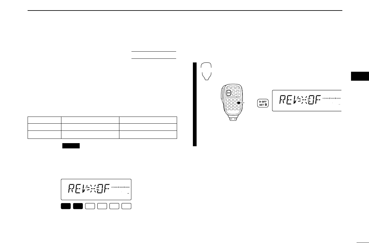
■Reversed duplex mode
When the reversed duplex mode is selected, the receive fre-
quency shifts. (Transmit frequency shifts in normal duplex mode.)
Each receive and transmit frequency is shown in the table
below with the following conditions;
Input frequency : 145.30 MHz
Direction : – (negative)
Offset frequency : 0.6 MHz
qPush [SET ] to enter set mode.
wPush [SET] or [MONI] several times until the “REV” dis-
play appears as shown below.
eRotate [DIAL] to turn the reversed duplex mode ON or
OFF.
rPush any other key than [SET] or [MONI] to exit set mode.
zPush [
SET
B(D-OFF)] to enter set mode.
x
Push [
SET
B(D-OFF)] or [
ENT
C(T-OFF)] until
“REV” appears.
cPush [YY]or [ZZ]to set the reversed duplex
mode ON and OFF.
vPush [
CLR
A(MW)] to exit set mode.
LOCK
S
E
T
ANM
MONI
DUP
LOW
T-SCAN
TONE
PRIO
M/CALL
SCAN
V/MHz
DIGITAL PRIO AO BUSY
MUTE
NAR
MID
LOW
Push
SET
B
LOCK
S
E
T
ANM
MONI
DUP
LOW
T-SCAN
TONE
PRIO
M/CALL
SCAN
V/MHz
DIGITAL PRIO AO BUSY
MUTE
NAR
MID
LOW
LOCK
USING
SET MODE
Reversed OFF ON
Rx frequency 145.30 MHz 144.70 MHz
Tx frequency 144.70 MHz 145.30 MHz
23
4REPEATER OPERATION
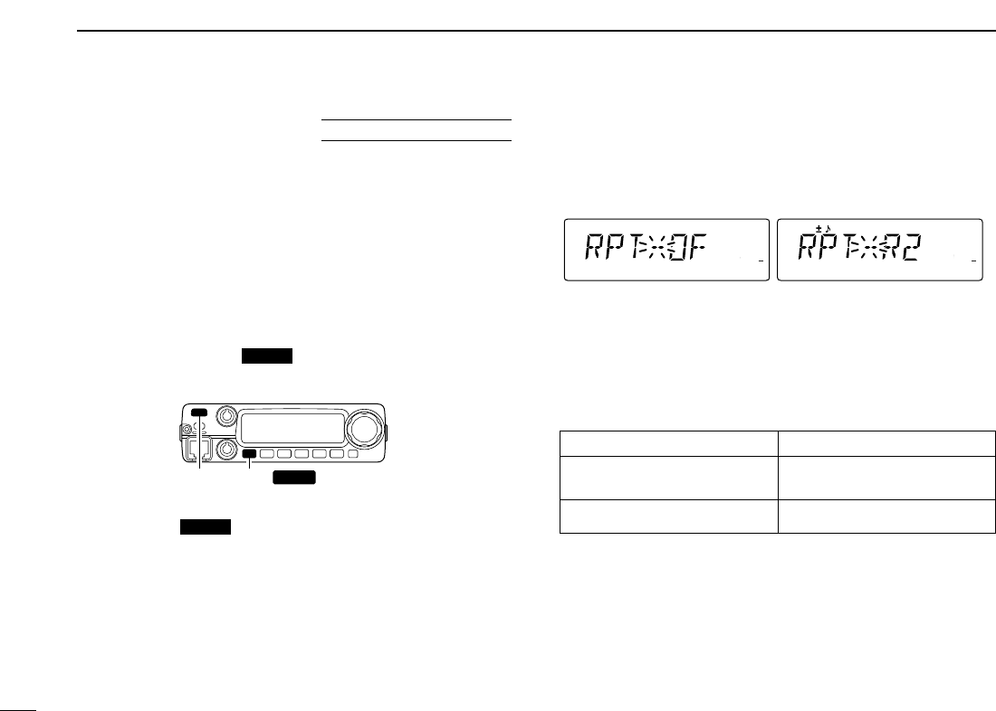
■Auto repeater
(U.S.A. version only)
The USA and CSA versions automatically activate the re-
peater settings (DUP– or DUP+ and tone encoder ON/OFF) when
the operating frequency falls within the general repeater out-
put frequency range and deactivate them when outside of the
range.
DSetting the auto repeater function ON/OFF
qPush [PWR] to turn power OFF.
w
While pushing
[SET ]
, turn power ON to enter initial
set mode.
ePush [SET ] several times until the “RPT” display
appears as shown above right.
rRotate [DIAL] to turn the auto repeater function to “R1,”
“R2” or OFF.
• “R1”: auto repeater is ON, tone encoder is OFF.
• “R2”: auto repeater is ON, tone encoder is ON.
tPush [PWR] to exit initial set mode.
DFrequency range and offset direction
LOCK
S
E
T
ANM
MONI
DUP
LOW
T-SCAN
TONE
PRIO
M/CALL
SCAN
V/MHz
DIGITAL PRIO AO BUSY
MUTE
NAR
MID
LOW
LOCK
S
E
T
ANM
MONI
DUP
LOW
T-SCAN
TONE
PRIO
M/CALL
SCAN
V/MHz
DIGITAL PRIO AO BUSY
MUTE
NAR
MID
LOW
Auto repeater function is
turned OFF.
Auto repeater function is ON,
tone encoder is ON.
LOCK
[PWR] [SET LOCK ]
LOCK
USING
INITIAL SET MODE
Frequency range Duplex direction
145.200–145.495 MHz “–” appears
146.610–146.995 MHz
147.000–147.395 MHz “+” appears
24
5
MEMORY OPERATION
4
5
■General description
The transceiver has 207 memory channels including 6 scan
edge memory channels (3 pairs), and 1 call channel. Each of
these channels can be individually programmed with operat-
ing frequency (pgs. 9, 10), duplex direction (p. 19) and offset
(p. 21), subaudible tone encoder or tone squelch and its tone
frequency (pgs. 19, 48–50) and skip information* (p. 41).
In addition, a total of 10 memory banks, A to J, are available
for usage by group, etc.
*except for scan edge memory channels.
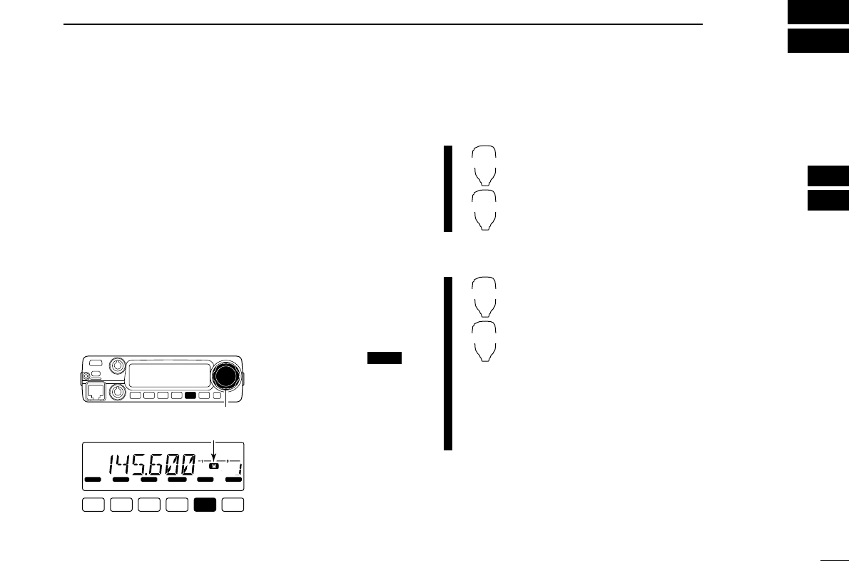
■Memory channel selection
DUsing the tuning dial
qPush [M/CALL ]
once or twice to select
memory mode.
•“M” indicator appears
w
Rotate
[DIAL]
to select
the desired memory
channel.
• Programmed memory
channels only can be se-
lected.
DUsing the [Y]/[Z] keys
zPush [MR/CALL] to select memory mode.
xPush [YY]or [ZZ]to select and set the desired
memory channel.
• Pushing [YY]/[ZZ]for 1 sec. activates a scan.
•
If scan is activated, push [YY]/[ZZ]again or push
[
CLR
A(MW)] to stop it.
DUsing the keypad
zPush [MR/CALL] to select memory mode.
xPush [
ENT
C(T-OFF)] to activate the keypad
for numeral input.
cPush 3 appropriate digit keys to input a chan-
nel number.
• When inputting non-programmed channel num-
bers, the previous memory channel appears.
• Push only 1 appropriate digit key, [
MONI
1(ANM)],
[
SCAN
2(T-SCAN)] or [
PRIO
3(PTT-M)], then push
[MM(TONE-1)] or [
SQL
ZZ#(16KEY-L)] to select scan
edge channels. “MM” and “#” can be used for “A”
and “b” respectively.
MR/CALL
Y/Z
MR/CALL
Y/Z
PRIO
LOCK
S
E
T
ANM
MONI
DUP
LOW
T-SCAN
TONE
PRIO
M/CALL
SCAN
V/MHz
DIGITAL PRIO AO BUSY
MUTE
NAR
MID
LOW
[DIAL]
Appears
25
5MEMORY OPERATION
■Programming a memory channel
VFO settings, including the set mode contents such as sub-
audible tone frequency, etc., can be programmed into a mem-
ory channel.
qSet the desired frequency in VFO mode.
➥Push [V/MHz ] to select VFO mode.
➥Set the frequency using [DIAL].
➥Set other data (e.g. tone frequency, duplex information,
etc.) if required.
wPush [S.MW ] momentarily.
•“M” indicator and the memory channel number blink.
eRotate [DIAL] to select the memory channel to be pro-
grammed.
• Memory channels not yet programmed are blank.
rPush [S.MW ] for 1 sec. to program.
• 3 beeps sound
• Memory channel number automatically increases when contin-
uing to push [S.MW ] after programming.
✔CONVENIENT
Memory programming can be performed in versatile ways
e.g. memory channel to the same (or different) memory chan-
nel, memory channel to the call channel, etc.
MW
MW
MW
SCAN
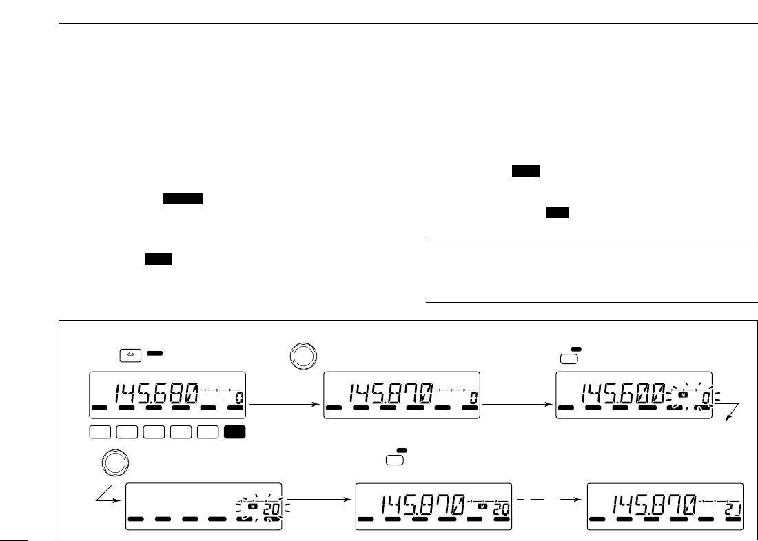
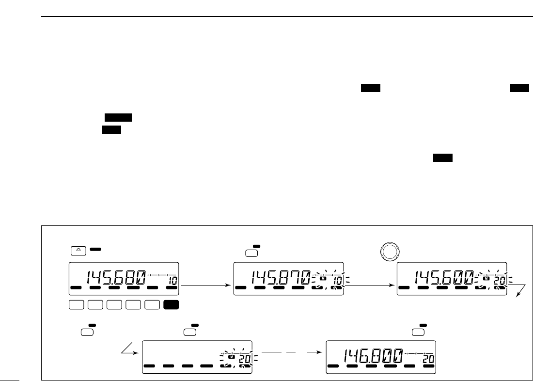
[EXAMPLE]: Programming 145.870 MHz into memory channel 20 (blank channel) via the front panel.
LOCK
S
E
T
ANM
MONI
DUP
LOW
T-SCAN
TONE
PRIO
M/CALL
SCAN
V/MHz
SCAN
V/MHz
MW
S.MW
DIGITAL PRIO AO BUSY
MUTE
NAR
MID
LOW
LOCK
S
E
T
ANM
MONI
DUP
LOW
T-SCAN
TONE
PRIO
M/CALL
SCAN
V/MHz
DIGITAL PRIO AO BUSY
MUTE
NAR
MID
LOW
LOCK
S
E
T
ANM
MONI
DUP
LOW
T-SCAN
TONE
PRIO
M/CALL
SCAN
V/MHz
DIGITAL PRIO AO BUSY
MUTE
NAR
MID
LOW
LOCK
S
E
T
ANM
MONI
DUP
LOW
T-SCAN
TONE
PRIO
M/CALL
SCAN
V/MHz
DIGITAL PRIO AO BUSY
MUTE
NAR
MID
LOW
LOCK
S
E
T
ANM
MONI
DUP
LOW
T-SCAN
TONE
PRIO
M/CALL
SCAN
V/MHz
DIGITAL PRIO AO BUSY
MUTE
NAR
MID
LOW
LOCK
S
E
T
ANM
MONI
DUP
LOW
T-SCAN
TONE
PRIO
M/CALL
SCAN
V/MHz
DIGITAL PRIO AO BUSY
MUTE
NAR
MID
LOW
MW
S.MW
( )
Push Rotate for setting frequency, etc. Push momentarily.
Rotate Push for 1 sec.
and continue to push
➠
Beep
Beep
Beep
“
“
“
“
“
26
5
MEMORY OPERATION
5
DProgramming a memory channel via the microphone
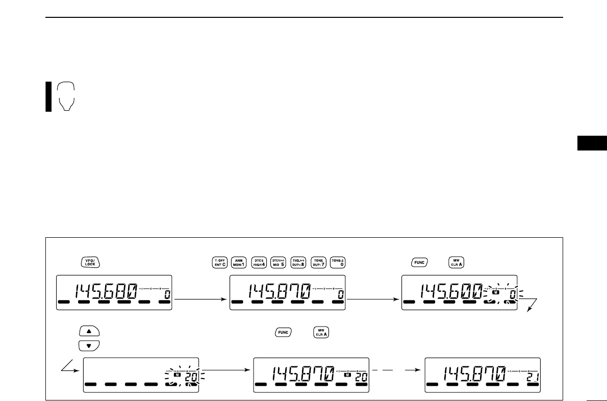
[EXAMPLE]: Programming 145.870 MHz into memory channel 20 (blank channel) via the microphone.
LOCK
S
E
T
ANM
MONI
DUP
LOW
T-SCAN
TONE
PRIO
M/CALL
SCAN
V/MHz
DIGITAL PRIO AO BUSY
MUTE
NAR
MID
LOW
LOCK
S
E
T
ANM
MONI
DUP
LOW
T-SCAN
TONE
PRIO
M/CALL
SCAN
V/MHz
DIGITAL PRIO AO BUSY
MUTE
NAR
MID
LOW
LOCK
S
E
T
ANM
MONI
DUP
LOW
T-SCAN
TONE
PRIO
M/CALL
SCAN
V/MHz
DIGITAL PRIO AO BUSY
MUTE
NAR
MID
LOW
LOCK
S
E
T
ANM
MONI
DUP
LOW
T-SCAN
TONE
PRIO
M/CALL
SCAN
V/MHz
DIGITAL PRIO AO BUSY
MUTE
NAR
MID
LOW
LOCK
S
E
T
ANM
MONI
DUP
LOW
T-SCAN
TONE
PRIO
M/CALL
SCAN
V/MHz
DIGITAL PRIO AO BUSY
MUTE
NAR
MID
LOW
LOCK
S
E
T
ANM
MONI
DUP
LOW
T-SCAN
TONE
PRIO
M/CALL
SCAN
V/MHz
DIGITAL PRIO AO BUSY
MUTE
NAR
MID
LOW
Beep
Beep
Beep
“
“
“
“
“
Push Push Push then momentarily.
Push Push then 1 sec.
and continue to push
➠
The microphone can also be used to program mem-
ory channels.
zSet the desired frequency in VFO mode.
➥Push [VFO/LOCK] to select VFO mode.
➥Set the frequency using the keypad.
➥Set other data (e.g. offset frequency, duplex direction, sub-
audible tone encoder ON/OFF and its frequency), if neces-
sary.
xPush [FUNC] then [
CLR
A(MW)] momentarily.
cSelect the memory channel to be programmed.
➥Push [YY]or [ZZ]to select the memory channel (direct nu-
meral input cannot be used).
vPush [FUNC] then [
CLR
A(MW)] for 1 sec. to program.
➥3 beeps may sound and the VFO contents (including
the subaudible tone frequency, etc.) are programmed.
➥Memory channel number increases when continuing to
push [
CLR
A(MW)] after programming.
MW
27
5MEMORY OPERATION
■
Transferring memory contents
This function transfers a memory channel’s contents to VFO
(or another memory/call channel). This is useful when search-
ing for signals around a memory channel frequency and for
recalling the offset frequency, subaudible tone frequency etc.
DMemory/call➪VFO
qSelect the memory/call channel to be transferred.
➥Push [M/CALL ] to select memory mode, then ro-
tate [DIAL] to select the desired memory channel.
➥Push [M/CALL ] for 1 sec. to select the call chan-
nel.
wPush [S.MW ] for 1 sec. to transfer the selected mem-
ory/call channel contents to the VFO.
• VFO mode is selected automatically.
zSelect the memory/call channel to be
transferred.
➥Push [MR/CALL] to select memory mode,
then select the desired memory channel
via [YY]/[ZZ]or keypad.
➥Push [MR/CALL] for 1 sec. to select the
call channel.
xPush [FUNC], then [
CLR
A(MW)] for 1 sec. to
transfer the selected memory/call channel
contents to the VFO.
• VFO mode is selected automatically.
MR/CALL
MW
[Y]/[Z]
MW
PRIO
PRIO
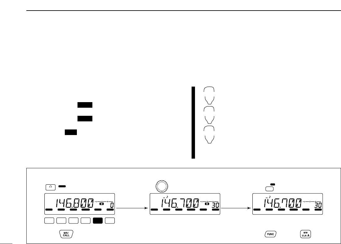
[EXAMPLE]: Transferring memory channel 30 contents to VFO.
LOCK
S
E
T
ANM
MONI
DUP
LOW
T-SCAN
TONE
PRIO
M/CALL
SCAN
V/MHz
PRIO
M/CALL
MW
S.MW
DIGITAL PRIO AO BUSY
MUTE
NAR
MID
LOW
LOCK
S
E
T
ANM
MONI
DUP
LOW
T-SCAN
TONE
PRIO
M/CALL
SCAN
V/MHz
DIGITAL PRIO AO BUSY
MUTE
NAR
MID
LOW
LOCK
S
E
T
ANM
MONI
DUP
LOW
T-SCAN
TONE
PRIO
M/CALL
SCAN
V/MHz
DIGITAL PRIO AO BUSY
MUTE
NAR
MID
LOW
( )
Push to select memory mode. Rotate for setting memory channel. Push for 1 sec.
HM-133V operation:
Front panel operation:
Push to select memory mode. Select memory channel. Push then push for 1 sec.
28
5
MEMORY OPERATION
5
DMemory/call➪call/memory
qSelect the memory/call channel to be transferred.
➥
Push
[M/CALL ]
to select memory mode, then ro-
tate
[DIAL]
to select the desired memory channel.
➥
Push [M/CALL ] for 1 sec. to select the call channel.
wPush [S.MW ] momentarily.
•“M” indicator and “– –” indication blink, and shows VFO condi-
tions.
eRotate [DIAL] to select the target memory channel.
• “C” blinks when the call channel is selected.
• Scan edge channels, 1A/1b, 2A/2b, 3A/3b, can also be selected.
rPush [S.MW ] for 1 sec. to transfer the selected mem-
ory/call channel contents to the target memory.
• The targeted memory and transferred contents are indicated.
zSelect the memory/call channel to be trans-
ferred.
➥Push [MR/CALL] to select memory mode,
then select the desired memory channel
via [YY]/[ZZ]or keypad.
➥Push [MR/CALL] for 1 sec. to select the
call channel.
x
Push [FUNC], then [
CLR
A(MW)] momentarily.
•“M” indicator and “– –” indication blink, and shows
VFO conditions.
cPush [YY]/[ZZ]to select the target memory
channel.
• “C” blinks when the call channel is selected.
• Scan edge channels can also be selected.
• The keypad cannot be used for the selection.
vPush [FUNC] then push [
CLR
A(MW)] for
1 sec. to transfer the selected memory/call
channel contents to the target memory.
• The targeted memory and transferred contents
are indicated.
MR/CALL
MW
[Y]/[Z]
MW
MW
PRIO
PRIO
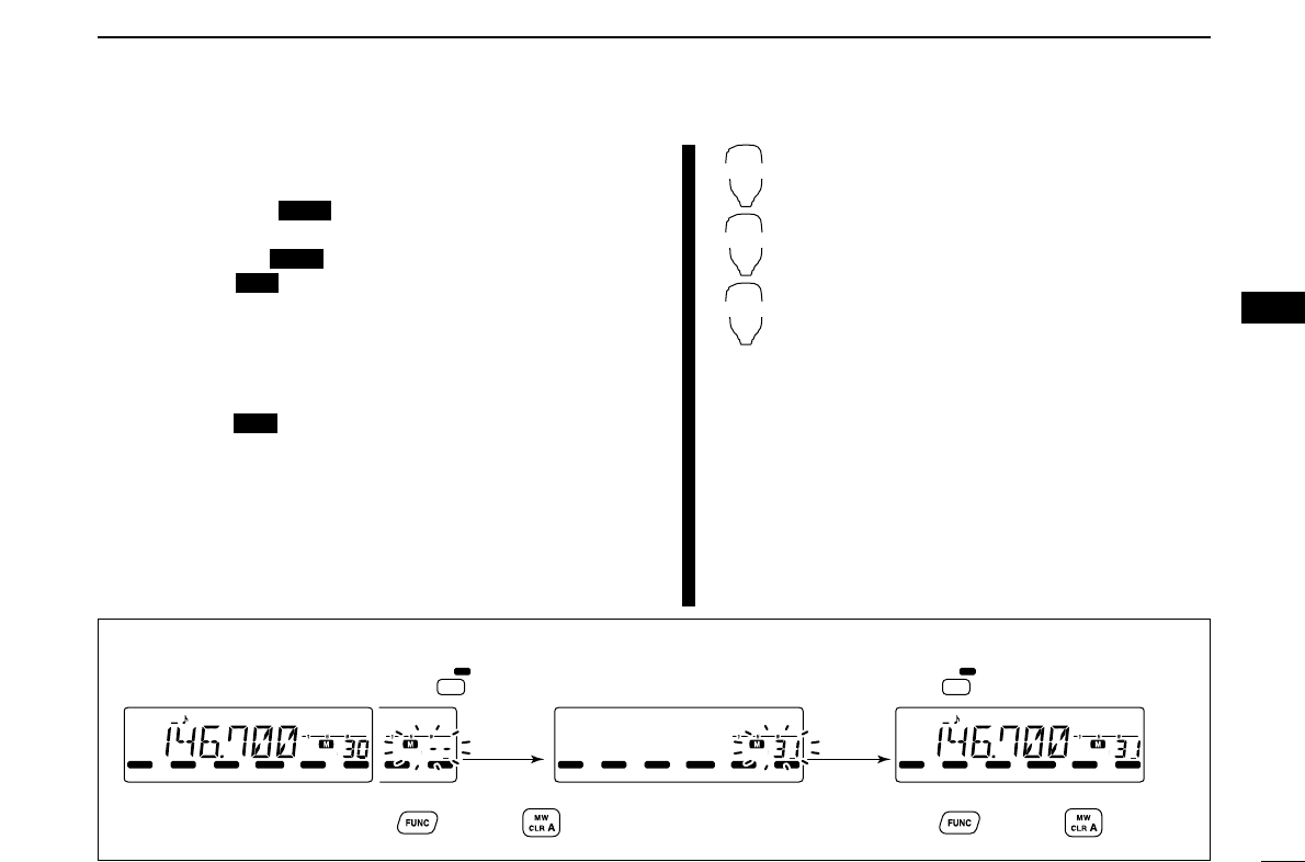
[EXAMPLE]: Transferring memory channel 30 contents to channel 31.
PRIO
M/CALL
SCAN
V/MHz
AO BUSY
LOCK
S
E
T
ANM
MONI
DUP
LOW
T-SCAN
TONE
PRIO
M/CALL
SCAN
V/MHz
DIGITAL PRIO AO BUSY
MUTE
NAR
MID
LOW
LOCK
S
E
T
ANM
MONI
DUP
LOW
T-SCAN
TONE
PRIO
M/CALL
SCAN
V/MHz
DIGITAL PRIO AO BUSY
MUTE
NAR
MID
LOW
LOCK
S
E
T
ANM
MONI
DUP
LOW
T-SCAN
TONE
PRIO
M/CALL
SCAN
V/MHz
DIGITAL PRIO AO BUSY
MUTE
NAR
MID
LOW
MW
S.MW MW
S.MW
Select the memory channel, then push . Select the target channel. Push for 1 sec.
HM-133V operation:
Front panel operation:
Push then push for 1 sec.Select the memory channel, push then push .
29
5MEMORY OPERATION
[EXAMPLE]: Clearing memory channel 20.
LOCK
S
E
T
ANM
MONI
DUP
LOW
T-SCAN
TONE
PRIO
M/CALL
SCAN
V/MHz
SCAN
V/MHz
DIGITAL PRIO AO BUSY
MUTE
NAR
MID
LOW
LOCK
S
E
T
ANM
MONI
DUP
LOW
T-SCAN
TONE
PRIO
M/CALL
SCAN
V/MHz
DIGITAL PRIO AO BUSY
MUTE
NAR
MID
LOW
LOCK
S
E
T
ANM
MONI
DUP
LOW
T-SCAN
TONE
PRIO
M/CALL
SCAN
V/MHz
DIGITAL PRIO AO BUSY
MUTE
NAR
MID
LOW
LOCK
S
E
T
ANM
MONI
DUP
LOW
T-SCAN
TONE
PRIO
M/CALL
SCAN
V/MHz
DIGITAL PRIO AO BUSY
MUTE
NAR
MID
LOW
LOCK
S
E
T
ANM
MONI
DUP
LOW
T-SCAN
TONE
PRIO
M/CALL
SCAN
V/MHz
DIGITAL PRIO AO BUSY
MUTE
NAR
MID
LOW
MW
S.MW
MW
S.MW MW
S.MW
MW
S.MW
( )
Push to select VFO. Push momentarily. Rotate for selecting memory channel..
Push momentarily, then push again for 1 sec. Push any other keys than .
Beep
Beep
Beep
“
“
“
“
“
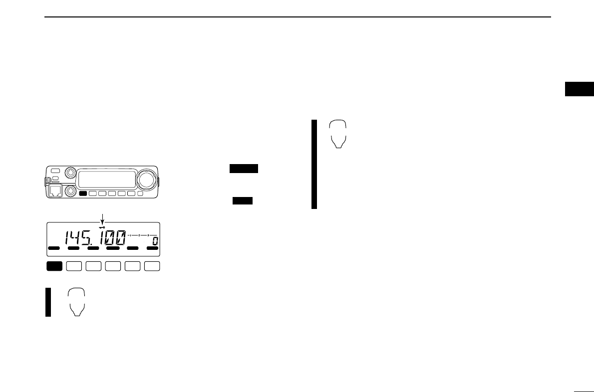
■Memory clearing
Contents of programmed memories can be cleared (blanked),
if desired.
qPush [V/MHz ] to select VFO mode.
wPush [S.MW ] momentarily.
•“M” indicator and the memory channel number blink.
eRotate [DIAL] to select the memory channel to be cleared.
• Memory channels not yet programmed are blank.
rPush [S.MW ] momentarily, then push [S.MW ]
again for 1 sec.
☞This operation must be performed within 1.5 sec.
• 3 beeps sound, then the frequency is cleared.
•“M” indicator blinks continuously.
• When clearing the call channel, the current VFO conditions are
re-programmed into the call channel automatically.
tPush any key, except [S.MW ], to return to VFO
mode.
☞NOTE: Be careful!— the contents of cleared memories
CANNOT be recalled.
MW
MWMW
MW
SCAN
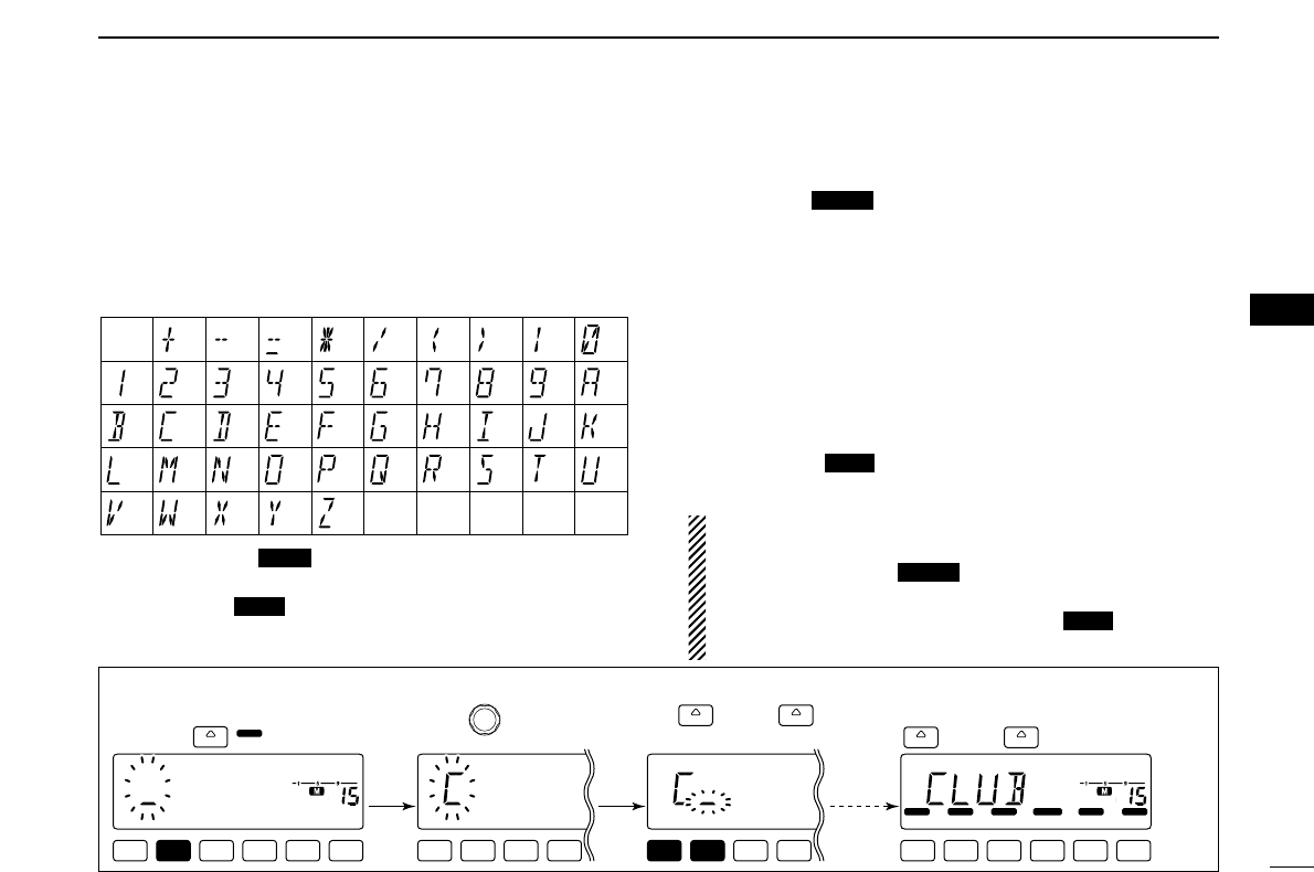
30
5
MEMORY OPERATION
5
■Programming channel names
Each memory channel and the call channel can be pro-
grammed with an alphanumeric channel name for easy
recognition and can be indicated independently by channel.
Names can be a maximum of 6 characters— see the table
below for available characters.
qPush [M/CALL ] to select memory mode.
w
Rotate
[DIAL]
to select the desired memory channel.
ePush [MONI ] for 1 sec. to select channel name indi-
cation mode.
• 1 short and 1 long beep sound.
rPush [SET ] to select the channel name program-
ming condition.
• Frequency readouts disappear.
tRotate [DIAL] to select the desired character.
• The selected character blinks.
yPush [SET] or [MONI] to move the cursor to left or right,
respectively.
uRepeat steps tand yuntil the desired channel names
are displayed.
iPush any other key than [SET] or [MONI] to program the
name and exit the channel name programming condition.
oPush [MONI ] for 1 sec. to return to frequency indi-
cation if desired.
IMPORTANT!: Once channel name indication mode is
selected, always access the channel name programming
condition when [SET ] is pushed.
When set mode accessing is necessary, cancel the chan-
nel name indication by pushing [MONI ] for 1 sec.,
then access to set mode.
ANM
LOCK
ANM
LOCK
ANM
PRIO
(1)
(B)
(L)
(V)
(+)
(2)
(C)
(
M
)
(
W
)
(–)
(3)
(
D
)
(N)
(X)
(=)
(4)
(E)
(O)
(Y)
(✱)
(5)
(F)
(P)
(Z)
(/)
(6)
(G)
(
Q
)
(space)
(7)
(()
(
H
)
(
R
)
())
(8)
(I)
(S)
(|)
(9)
(J)
(T)
(0)
(A)
(
K
)
(U)
[EXAMPLE]: Programming “CLUB” into memory channel 1.
LOCK
S
E
T
ANM
MONI
DUP
LOW
T-SCAN
TONE
PRIO
M/CALL
SCAN
V/MHz
DIGITAL PRIO AO BUSY
MUTE
NAR
MID
LOW
LOCK
S
E
T
ANM
MONI
DUP
LOW
T-SCAN
TONE
PRIO
M/CALL
SCAN
V/MHz
DIGITAL PRIO AO BUSY
MUTE
NAR
MID
LOW
LOCK
S
E
T
ANM
MONI
DUP
LOW
MUTE
NAR
MID
LOW
LOCK
S
E
T
ANM
MONI
DUP
LOW
MUTE
NAR
MID
LOW
ANM
MONI
( )
LOCK
SET
( ) ANM
MONI
( )
LOCK
SET
( ) ANM
MONI
( )
Push any other keys than
or .
Select memory channel 15,
then push for 1 sec.
Push or
to move the cursor.
Rotate to select the
character.
Repeat
previous
steps.
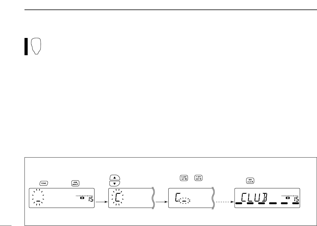
31
5MEMORY OPERATION
Channel names can also be programmed via the mi-
crophone.
zSelect the memory/call channel to be assigned memory
names.
➥Push [MR/CALL] to select memory mode, then select
the desired memory channel via [YY]/[ZZ]or keypad.
• Scan edge channels can also be selected.
➥Push [MR/CALL] for 1 sec. to select the call channel.
xPush [FUNC], then [
MONI
1(ANM)] momentarily.
cPush [
SET
B(D-OFF)].
• Frequency readouts disappear.
vPush [YY]/[ZZ]to select the desired character.
• The selected character blinks.
bPush [
SET
B(D-OFF)] or [
ENT
C(T-OFF)] to move the cur-
sor to left or right, respectively.
nRepeat steps vand buntil the desired channel names
are displayed.
mPush [
CLR
A(MW)] to program the name and exit the
channel name programming condition.
,Push [FUNC], then push [
MONI
1(ANM)] to return to fre-
quency indication if desired.
[EXAMPLE]: Programming “CLUB” into memory channel 15.
LOCK
S
E
T
ANM
MONI
DUP
LOW
T-SCAN
TONE
PRIO
M/CALL
SCAN
V/MHz
DIGITAL PRIO AO BUSY
MUTE
NAR
MID
LOW
LOCK
S
E
T
ANM
MONI
DUP
LOW
T-SCAN
TONE
PRIO
M/CALL
SCAN
V/MHz
DIGITAL PRIO AO BUSY
MUTE
NAR
MID
LOW
LOCK
S
E
T
ANM
MONI
DUP
LOW
MUTE
NAR
MID
LOW
LOCK
S
E
T
ANM
MONI
DUP
LOW
MUTE
NAR
MID
LOW
Repeat
previous
steps.
Push to select the character.
Select memory channel 15,
push , then push . Push .
Push or to move
the cursor.
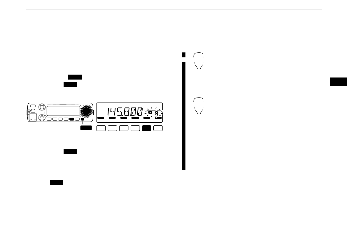
32
5
MEMORY OPERATION
5
■Memory bank selection
The IC-2200H has a total of 10 banks (A to J). Regular mem-
ory channels, 0 to 199. are assigned into the desired bank for
easy memory manegement.
qPush [M/CALL ] to select memory mode.
wPush [BANK ] to select memory bank condition.
• Bank initial blinks
eRotate [DIAL] to select the desired bank, A to J.
• Banks that have no programmed contents are skipped.
rPush [BANK ] to set the bank.
• Initial stops blinking.
tRotate [DIAL] to select the contents in the bank.
• No channel numbers are displayed for memory bank operation.
yTo return to regular memory condition, push
[BANK ] twice.
zPush [MR/CALL] to select memory mode.
xPush [BANK/OPTION] to select memory
bank condition.
• Bank initial blinks
cPush [YY]/[ZZ]to select the desired bank, A
to J.
• Only programmed memory bank can be se-
lected.
vPush
[
CLR
A(MW)]
to set the bank.
• Initial stops blinking.
bPush [YY]/[ZZ]to select the desired con-
tents in the bank.
• No channel numbers are displayed for memory
bank operation.
nTo return to regular memory condition,
push [BANK/OPTION] then
[
CLR
A(MW)]
.
BANK/OPTION
[Y]/[Z]
OPT
OPT
LOCK
S
E
T
ANM
MONI
DUP
LOW
T-SCAN
TONE
PRIO
M/CALL
SCAN
V/MHz
DIGITAL PRIO AO BUSY
MUTE
NAR
MID
LOW
[BANK OPT ]
[DIAL]
OPT
PRIO
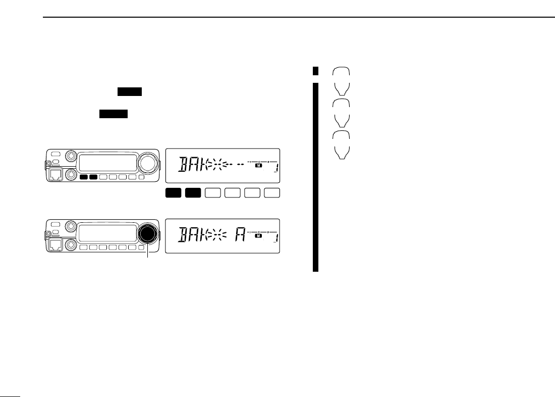
33
5MEMORY OPERATION
■Memory bank setting
qPush [M/CALL ] to select memory mode, then se-
lect the desired memory channel via [DIAL].
wPush [SET ] enter the set mode.
ePush [SET] or [MONI] several times until “BAK” appears.
• “– –” indication blinks as follows.
rRotate [DIAL] to select the desired bank to be set.
tPush any other key than [SET] or [MONI] to set the chan-
nel into the bank and return to regular memory condition.
yRepeat steps qto tto set another memory channel into
the same or another bank.
zPush [MR/CALL] then select the desired
memory channel via [YY]/[ZZ]or keypad.
xPush [
SET
B(D-OFF)] to enter set mode.
cPush [
SET
B(D-OFF)] or [
ENT
C(T-OFF)]
several times until “BAK” appears.
vPush [YY]or [ZZ]to select the desired bank
to be set.
bPush [
CLR
A(MW)] to set the channel into
the bank and exit set mode.
nRepeat steps zto bto set an another
memory channel into the same or another
bank.
BANK/OPTION
MW
[Y]/[Z]
LOCK
S
E
T
ANM
MONI
DUP
LOW
T-SCAN
TONE
PRIO
M/CALL
SCAN
V/MHz
DIGITAL PRIO AO BUSY
MUTE
NAR
MID
LOW
[DIAL]
LOCK
S
E
T
ANM
MONI
DUP
LOW
T-SCAN
TONE
PRIO
M/CALL
SCAN
V/MHz
DIGITAL PRIO AO BUSY
MUTE
NAR
MID
LOW
LOCK
PRIO
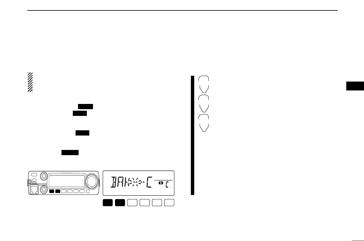
34
5
MEMORY OPERATION
5
■Transferring bank contents
Contents of programmed memory banks can be cleared or
transferred to another bank.
INFORMATION: Even if the memory bank contents are
cleared, the memory channel contents still remain pro-
grammed.
q
Select the desired bank contents to be transferred or erased.
➥Push [M/CALL ] to select memory mode.
➥Push [BANK ] then rotate [DIAL] to select the de-
sired memory bank.
• Bank initial blinks.
➥Push [BANK ] to select the bank then rotate
[DIAL] to select the desired contents.
• Bank initial stops blinking.
wPush [SET ] enter the set mode.
ePush [SET] or [MONI] several times until “BAK” appears.
• Bank initial appears.
eRotate [DIAL] to select the desired bank initial to transfer
or erase.
• Select “– –” indication when erasing the contents from the bank.
rPush any other key than [SET] or [MONI] to transfer or
erase. and return to regular memory condition.
yRepeat steps qto rfor transferring or erasing an an-
other banks contents.
zSelect the desired bank contents to be trans-
ferred or erased.
➥Push [MR/CALL] to select memory mode.
➥Push [BANK/OPTION], then select the de-
sired memory bank via [YY]/[ZZ].
➥Push [
CLR
A(MW)] to select the bank then
select the desired contents via [YY]/[ZZ].
xPush [
SET
B(D-OFF)] to enter set mode.
cPush [
SET
B(D-OFF)] or [
ENT
C(T-OFF)] sev-
eral times until “BAK” appears.
vPush [YY]/[ZZ]to select the desired bank initial
to transfer or erase.
• Select “-- --” indication when erasing the contents
from the bank.
bPush [
CLR
A(MW)] to set the bank and exit set
mode.
nRepeat steps zto bfor transferring or eras-
ing an another banks contents.
BANK
[Y]/[Z]
SET
LOCK
S
E
T
ANM
MONI
DUP
LOW
T-SCAN
TONE
PRIO
M/CALL
SCAN
V/MHz
DIGITAL PRIO AO BUSY
MUTE
NAR
MID
LOW
LOCK
OPT
OPT
PRIO
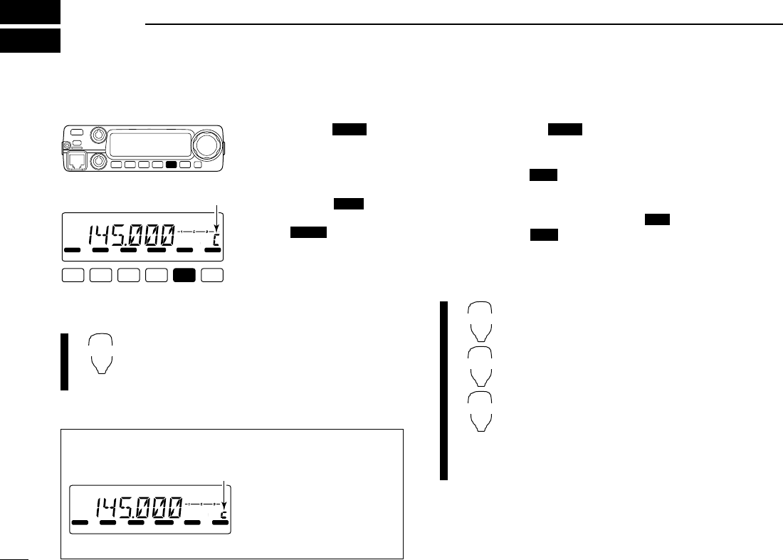
35
CALL CHANNEL OPERATION
6
■Call channel selection
➥Push [M/CALL ] once
or twice to select the call
channel.
• “C” appears instead of mem-
ory channel number indication.
• Push [M/CALL ] to re-
turn to memory mode, or push
[V/MHz ] to select VFO
mode.
➥Push [MR/CALL] for 1 sec. to select the call
channel.
• Push [MR/CALL]to select memory mode, or push
[VFO/LOCK] to select VFO mode.
■Call channel transferring
qPush [M/CALL ] several times to select the call
channel.
• “C” appears.
wPush [S.MW ] momentarily, then rotate [DIAL] to se-
lect the memory channel to transfer the contents to.
•“M” indicator and memory channel number blink.
• To transfer to the VFO, push [S.MW ] for 1 sec.
ePush [S.MW ] for 1 sec. to transfer when a momen-
tary push was used in the previous step.
• If channel names have been programmed into the call channel,
the names are also transferred.
zPush [MR/CALL] for 1 sec. to select the call
channel.
xPush [FUNC], [
CLR
A(MW)] momentarily,
then push [YY]/[ZZ]to select the memory
channel to transfer the contents to.
• To transfer to the VFO, push [FUNC], then push
[
CLR
A(MW)] for 1 sec.
cPush [FUNC], then [
CLR
A(MW)] for 1 sec. to
transfer when a momentary push was used in
the previous step.
• If channel names have been programmed into the
call channel, the names are also transferred.
MR/CALL
MW
[Y]/[Z]
MW
MW
MW
PRIO
MR/CALL
SCAN
PRIO
PRIO
LOCK
S
E
T
ANM
MONI
DUP
LOW
T-SCAN
TONE
PRIO
M/CALL
SCAN
V/MHz
DIGITAL PRIO AO BUSY
MUTE
NAR
MID
LOW
Appears
✔INFORMATION
When the VFO mode is se-
lected from the call channel,
a small “c” appears instead
of memory channel number.
LOCK
S
E
T
ANM
MONI
DUP
LOW
T-SCAN
TONE
PRIO
M/CALL
SCAN
V/MHz
DIGITAL PRIO AO BUSY
MUTE
NAR
MID
LOW
Small “c” shows VFO was
selected from the call channel.
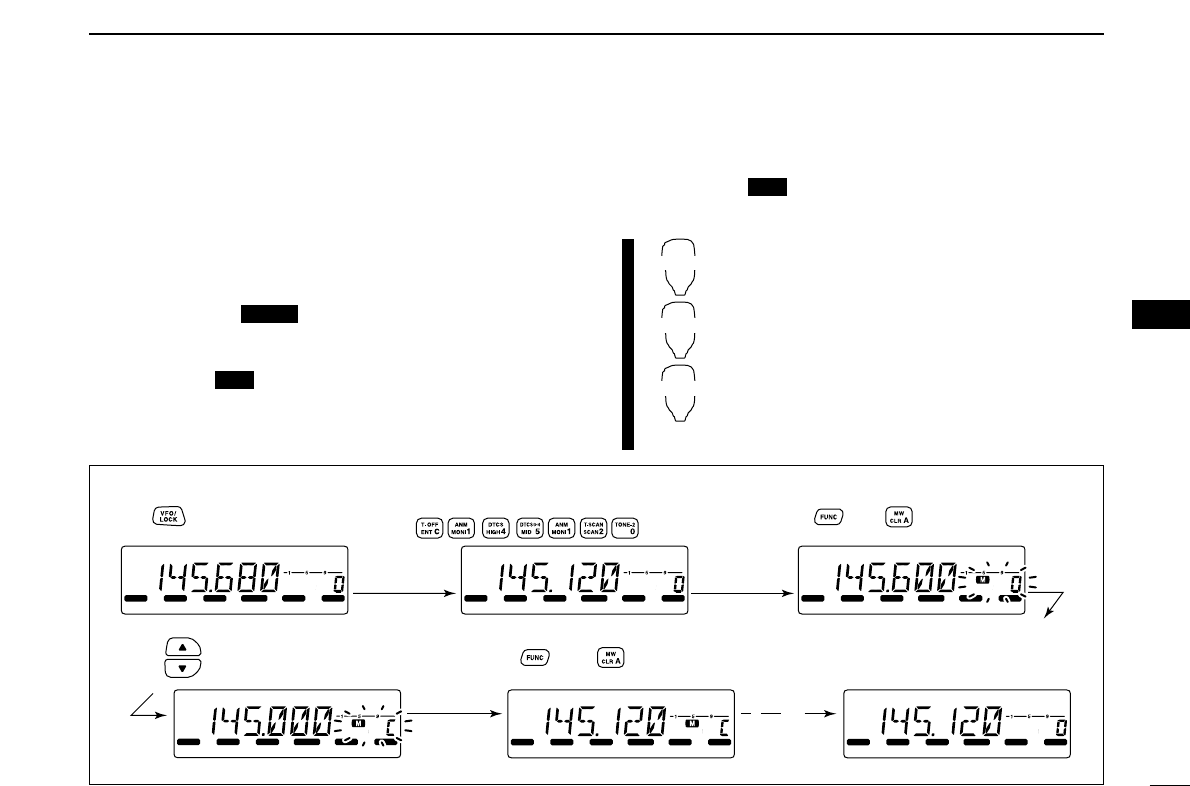
36
6
CALL CHANNEL OPERATION
6
■Programming a call channel
Operating frequency, duplex information, subaudible tone in-
formation (tone encoder or tone squelch ON/OFF and its fre-
quency) and alphanumeric channel names can also be
programmed into the call channel.
qSet the desired frequency in VFO mode.
➥Push [V/MHz ] to select VFO mode.
➥Set the frequency using [DIAL].
➥Set other data as desired.
wPush [S.MW ] momentarily.
eRotate [DIAL] to select the call channel
•“M” indicator and “C” blink.
rPush [S.MW ] for 1 sec. to program.
• 3 beeps sound and the unit returns to VFO mode automatically.
zSet the desired frequency in VFO mode.
➥Push [VFO/LOCK] to select VFO mode.
➥Set the frequency.
➥Set other data as desired.
x
Push [FUNC], then [
CLR
A(MW)] momentarily.
cSelect the call channel via [YY]or [ZZ].
vPush [FUNC] then [
CLR
A(MW)] for 1 sec. to
program.
• 3 beeps sound and the unit returns to VFO mode
automatically.
MR/CALL
MW
[Y]/[Z]
MW
MW
SCAN
[EXAMPLE]: Programming 145.120 MHz into the call channel via the microphone.
LOCK
S
E
T
ANM
MONI
DUP
LOW
T-SCAN
TONE
PRIO
M/CALL
SCAN
V/MHz
DIGITAL PRIO AO BUSY
MUTE
NAR
MID
LOW
LOCK
S
E
T
ANM
MONI
DUP
LOW
T-SCAN
TONE
PRIO
M/CALL
SCAN
V/MHz
DIGITAL PRIO AO BUSY
MUTE
NAR
MID
LOW
LOCK
S
E
T
ANM
MONI
DUP
LOW
T-SCAN
TONE
PRIO
M/CALL
SCAN
V/MHz
DIGITAL PRIO AO BUSY
MUTE
NAR
MID
LOW
LOCK
S
E
T
ANM
MONI
DUP
LOW
T-SCAN
TONE
PRIO
M/CALL
SCAN
V/MHz
DIGITAL PRIO AO BUSY
MUTE
NAR
MID
LOW
LOCK
S
E
T
ANM
MONI
DUP
LOW
T-SCAN
TONE
PRIO
M/CALL
SCAN
V/MHz
DIGITAL PRIO AO BUSY
MUTE
NAR
MID
LOW
LOCK
S
E
T
ANM
MONI
DUP
LOW
T-SCAN
TONE
PRIO
M/CALL
SCAN
V/MHz
DIGITAL PRIO AO BUSY
MUTE
NAR
MID
LOW
Beep
Beep
Beep
“
“
“
“
“
Push then for 1 sec.
➠
Set the frequency.
Push to select VFO mode. Push , then momentarily.
Push until large “C” appears.
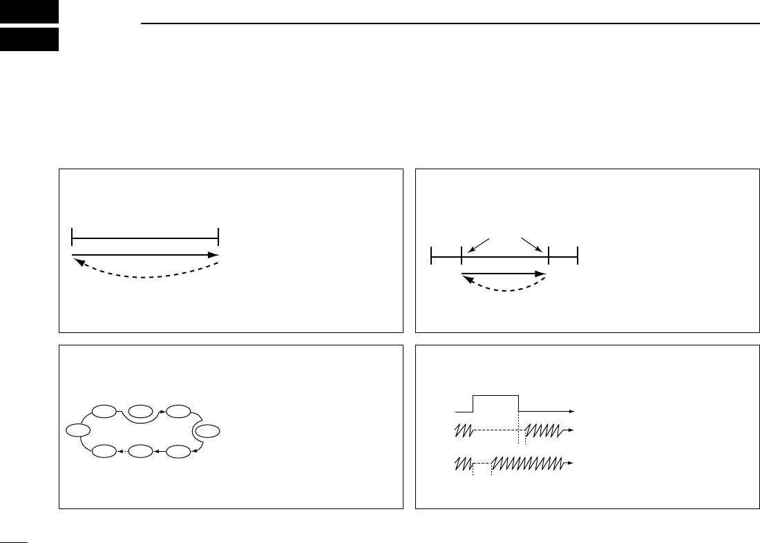
37
SCAN OPERATION
7
■Scan types
Scanning searches for signals automatically and makes it
easier to locate new stations for contact or listening purposes.
There are 3 scan types and 4 resume conditions to suit your
operating needs.
FULL SCAN (p. 38) Repeatedly scans all frequen-
cies over the entire band.
Used as the simplest scan
without any preliminary set-
tings necessary.
Band
edge
Band
edge
Scan
Jump
PROGRAMMED SCAN
(p. 38)
Repeatedly scans between
two user-programmed fre-
quencies. Used for checking
for frequencies within a speci-
fied range such as repeater
output frequencies, etc. 3
pairs of scan edges are avail-
able.
Band
edge
Band
edge
Scan edges
Scan
Jump
MEMORY SCAN (p. 38) Repeatedly scans memory
channels except those set as
skip channels. Used for often-
called channels and for by-
passing normally busy
channels such as repeater
frequencies.
SKIP
SKIP
M 0 M 4
M 1 M 2 M 3
M 5
M 199
M 6
SCAN RESUME
CONDITION (p. 42)
4 resume conditions are avail-
able: 3 timer scans and pause
scan. When receiving a sig-
nal, pause scan pauses until
the signal disappears; timer
scans pause for 5, 10 or
15 sec.
Pause
scan
Receiving
a signal
Timer
scan
Pausing
2 sec.
☞NOTE: A tone scan function is available to search for subaudible tones (e.g. when you want to find a subaudible tone fre-
quency necessary to open a repeater). See p. 51 for details.
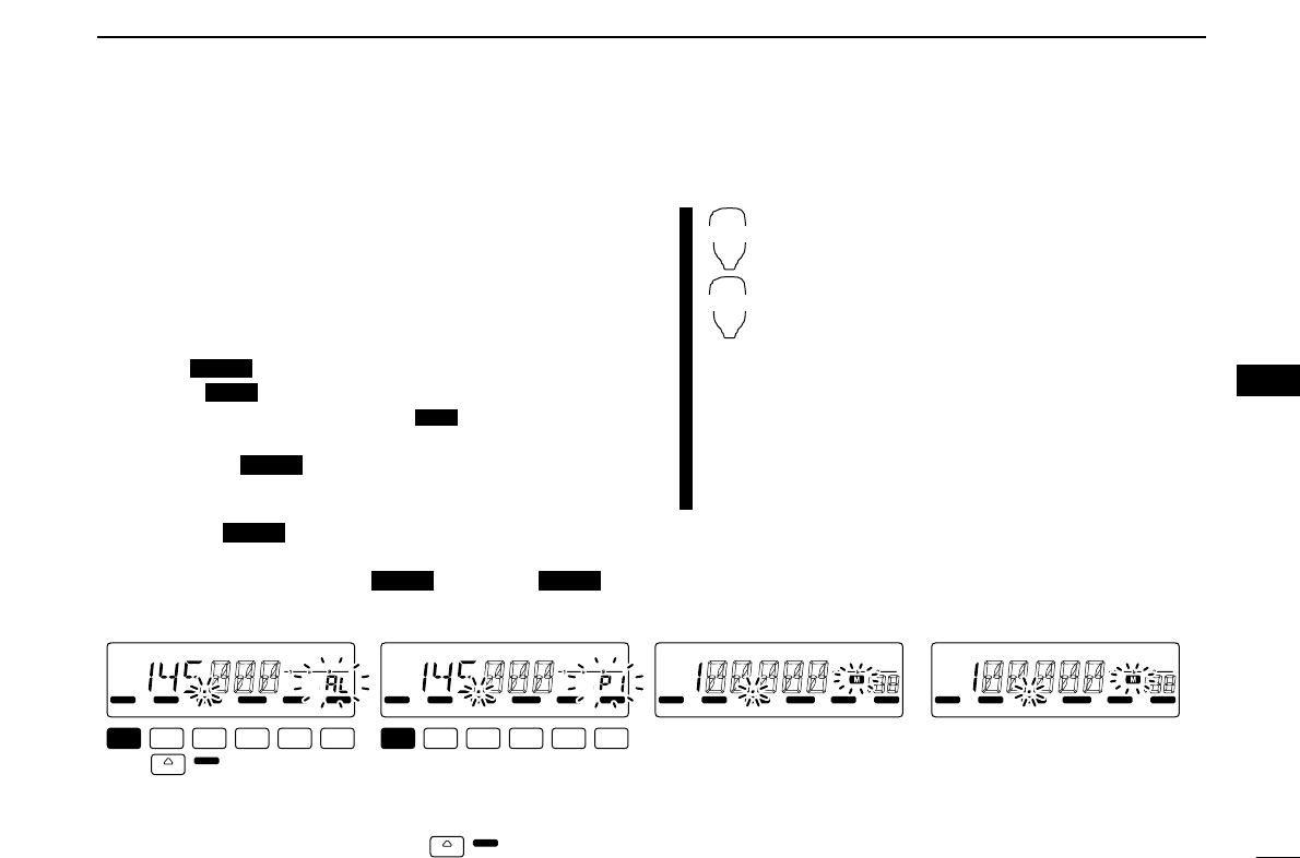
38
7
SCAN OPERATION
7
■Scan start/stop
DPreparation
Scan resume condition (p. 42); program the scan edges
(pgs. 39, 40); program 2 or more memory channels (pgs. 25,
26); set skip settings, if desired (p. 41).
DOperation
qSelect VFO mode for full/programmed scan with
[V/MHz ]; or memory mode for memory scan with
[M/CALL ].
• Select the desired bank with [BANK ] for bank scan.
wSet the squelch to the point where noise is just muted.
ePush [V/MHz ] for 1 sec. to start the scan.
• To change the scanning direction, rotate [DIAL].
• The memory channel readout blinks the scan type as follows:
rPush [SET ] to switch full and programmed scan
(P1, P2 and P3).
tTo stop the scan, push [SET ] or [V/MHz ].
zPush [VFO/LOCK] to select VFO mode for
full/programmed scan; push [MR/CALL] to se-
lect memory mode for memory scan.
• Push [BANK/OPTION] to select a bank for bank
scan.
xSet the squelch to the point where noise is just
muted.
cPush [
SCAN
2(T-SCAN)] to start the scan.
• Push [YY]or [ZZ]for 1 sec. also starts the scan.
vPush [
SET
B(D-OFF)] to switch full and pro-
grammed scan (P1, P2 and P3).
bTo stop the scan push [
SCAN
2(T-SCAN)] or
[
CLR
A(MW)].
SCAN
2
SET
B
SCANLOCK
LOCK
SCAN
OPT
PRIO
SCAN
LOCK
S
E
T
ANM
MONI
DUP
LOW
T-SCAN
TONE
PRIO
M/CALL
SCAN
V/MHz
DIGITAL PRIO AO BUSY
MUTE
NAR
MID
LOW
LOCK
S
E
T
ANM
MONI
DUP
LOW
T-SCAN
TONE
PRIO
M/CALL
SCAN
V/MHz
DIGITAL PRIO AO BUSY
MUTE
NAR
MID
LOW
LOCK
S
E
T
ANM
MONI
DUP
LOW
T-SCAN
TONE
PRIO
M/CALL
SCAN
V/MHz
DIGITAL PRIO AO BUSY
MUTE
NAR
MID
LOW
LOCK
S
E
T
ANM
MONI
DUP
LOW
T-SCAN
TONE
PRIO
M/CALL
SCAN
V/MHz
DIGITAL PRIO AO BUSY
MUTE
NAR
MID
LOW
• During full scan • During programmed scan • During memory scan • During Bank scan
Indicates scan edge channels.
• P1 stands for 1A/1b
• P1 to P3 are available when they
are programmed, and switches
with .
Push to select full or
programmed scan (P1, P2
and P3) in sequence.
LOCK
SET
( )
LOCK
SET
( )
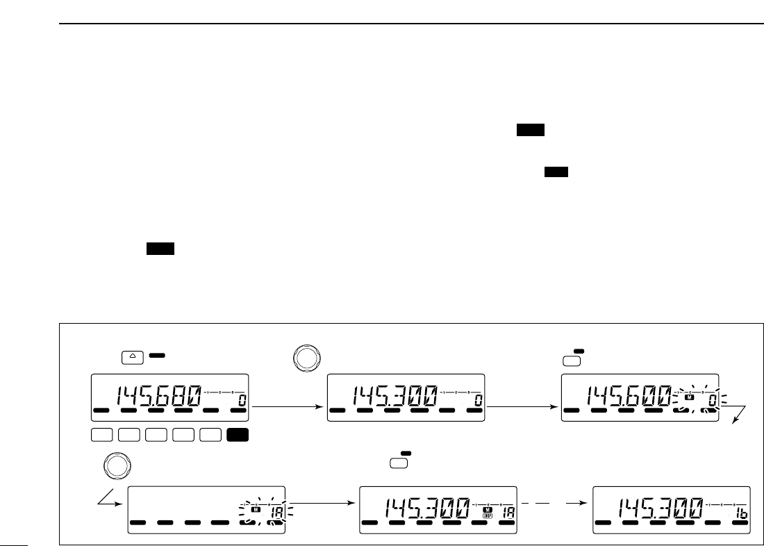
39
7SCAN OPERATION
■Scan edges programming
Scan edges can be programmed in the same manner as
memory channels. Scan edges are programmed into scan
edges, 1A/1b to 3A/3b, in memory channels.
qSet the edge frequency of the desired frequency range in
VFO mode:
➥Set the frequency using [DIAL].
➥Set other data (e.g. repeater settings, etc.) if desired.
wPush [S.MW ] momentarily.
•“M” indicator and channel number blink.
eRotate [DIAL] to select one of scan edge channel, 1A, 2A
or 3A.
rPush [S.MW ] for 1 sec. to program.
• 3 beeps sound and VFO is automatically selected.
• Scan edge 1b, 2b or 3b is automatically selected when continu-
ing to push [S.MW ] after programming.
tTo program a frequency for the other pair of scan edges,
1b, 2b or 3b, repeat steps qand r.
• If the same frequency is programmed into a pair of scan edges,
programmed scan will not function.
MW
MW
MW
[EXAMPLE]: Programming 145.300 MHz into scan edges 1A.
LOCK
S
E
T
ANM
MONI
DUP
LOW
T-SCAN
TONE
PRIO
M/CALL
SCAN
V/MHz
SCAN
V/MHz
MW
S.MW
DIGITAL PRIO AO BUSY
MUTE
NAR
MID
LOW
LOCK
S
E
T
ANM
MONI
DUP
LOW
T-SCAN
TONE
PRIO
M/CALL
SCAN
V/MHz
DIGITAL PRIO AO BUSY
MUTE
NAR
MID
LOW
LOCK
S
E
T
ANM
MONI
DUP
LOW
T-SCAN
TONE
PRIO
M/CALL
SCAN
V/MHz
DIGITAL PRIO AO BUSY
MUTE
NAR
MID
LOW
LOCK
S
E
T
ANM
MONI
DUP
LOW
T-SCAN
TONE
PRIO
M/CALL
SCAN
V/MHz
DIGITAL PRIO AO BUSY
MUTE
NAR
MID
LOW
LOCK
S
E
T
ANM
MONI
DUP
LOW
T-SCAN
TONE
PRIO
M/CALL
SCAN
V/MHz
DIGITAL PRIO AO BUSY
MUTE
NAR
MID
LOW
LOCK
S
E
T
ANM
MONI
DUP
LOW
T-SCAN
TONE
PRIO
M/CALL
SCAN
V/MHz
DIGITAL PRIO AO BUSY
MUTE
NAR
MID
LOW
MW
S.MW
( )
Push Rotate for setting frequency, etc. Push momentarily.
Rotate Push for 1 sec.
and continue to push
➠
Beep
Beep
Beep
“
“
“
“
“
40
7
SCAN OPERATION
7
DProgramming scan edges via microphone
zSet the desired frequency in VFO mode.
➥Push [VFO/LOCK] to select VFO mode.
➥Set the frequency via the keypad or [YY]/[ZZ].
xPush [FUNC] then [
CLR
A(MW)] momentarily.
cPush [YY]or [ZZ]to select scan edge channels,
1A, 2A or 3A.
vPush [FUNC], then push [
CLR
A(MW)] for 1 sec.
to program.
• 3 beeps sound and VFO is automatically selected.
• Memory channel number advances to the next scan
edge channel, 1b, 2b or 3b, when continuing to push
[
CLR
A(MW)] after programming.
bTo program a frequency for the other scan edge channels,
repeat steps zto v.
MW
[EXAMPLE]: Programming 145.800 MHz into scan edges 1b.
LOCK
S
E
T
ANM
MONI
DUP
LOW
T-SCAN
TONE
PRIO
M/CALL
SCAN
V/MHz
DIGITAL PRIO AO BUSY
MUTE
NAR
MID
LOW
LOCK
S
E
T
ANM
MONI
DUP
LOW
T-SCAN
TONE
PRIO
M/CALL
SCAN
V/MHz
DIGITAL PRIO AO BUSY
MUTE
NAR
MID
LOW
LOCK
S
E
T
ANM
MONI
DUP
LOW
T-SCAN
TONE
PRIO
M/CALL
SCAN
V/MHz
DIGITAL PRIO AO BUSY
MUTE
NAR
MID
LOW
LOCK
S
E
T
ANM
MONI
DUP
LOW
T-SCAN
TONE
PRIO
M/CALL
SCAN
V/MHz
DIGITAL PRIO AO BUSY
MUTE
NAR
MID
LOW
LOCK
S
E
T
ANM
MONI
DUP
LOW
T-SCAN
TONE
PRIO
M/CALL
SCAN
V/MHz
DIGITAL PRIO AO BUSY
MUTE
NAR
MID
LOW
LOCK
S
E
T
ANM
MONI
DUP
LOW
T-SCAN
TONE
PRIO
M/CALL
SCAN
V/MHz
DIGITAL PRIO AO BUSY
MUTE
NAR
MID
LOW
Beep
Beep
Beep
“
“
“
“
“
Push Push then momentarily.
Push Push then 1 sec.
and continue to push
➠
Push
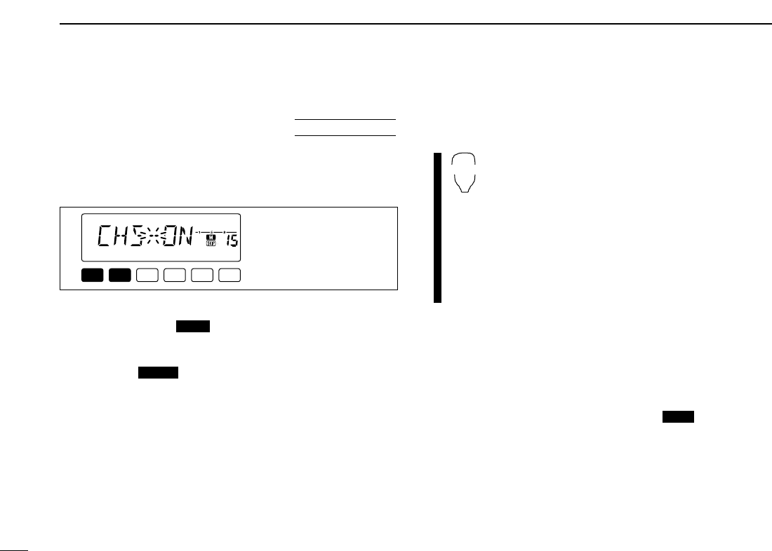
41
7SCAN OPERATION
■Skip channel setting
The memory skip function speeds up scanning by checking
only those memory channels not set as skip channels. Set
skip channels as follows.
qSelect a memory channel:
➥Push [M/CALL ] to select memory mode.
➥Rotate [DIAL] to select the desired channel to be a skip
channel.
wPush [SET ] to enter set mode.
ePush [SET] or [MONI] several times until “CHS” appears
as shown above.
rRotate [DIAL] to turn the skip function ON or OFF for the
selected channel.
•“~” appears : The channel is skipped during scan.
(CHS-ON)
•“~” disappears : The channel is scanned during scan.
(CHS-OFF)
tPush any other key than [SET] or [MONI] to exit set mode.
zSelect a memory channel.
➥Select memory mode by pushing [MR/CALL].
➥Push [YY]or [ZZ]to select the desired channel
to be a skip channel.
xPush [
SET
B(D-OFF)] to enter set mode.
cPush [
SET
B(D-OFF)] or [
ENT
C(T-OFF)] several
times until “CHS” appears as shown at left.
vPush [YY]or [ZZ]to set or cancel the skip setting.
• See item rat left for skip indicator details.
bPush [
CLR
A(MW)] to exit set mode.
☞NOTES:
Even though scan edge channels cannot be set as skip
channels, they ARE skipped during memory scan.
SET mode cannot be accessed when memory names are
displayed. To set the scan resume condition, return to fre-
quency indication by pushing [MONI ] on the front
panel for 1 sec., or push [FUNC] then [
MONI
1(ANM)] (HM-
133V) to cancel the channel name indication, then set as
described on this page.
ANM
SET
B
LOCK
PRIO
LOCK
S
E
T
ANM
MONI
DUP
LOW
T-SCAN
TONE
PRIO
M/CALL
SCAN
V/MHz
DIGITAL PRIO AO BUSY
MUTE
NAR
MID
LOW
The display shows that
memory channel 1 is set
as a skip channel.
USING
SET MODE
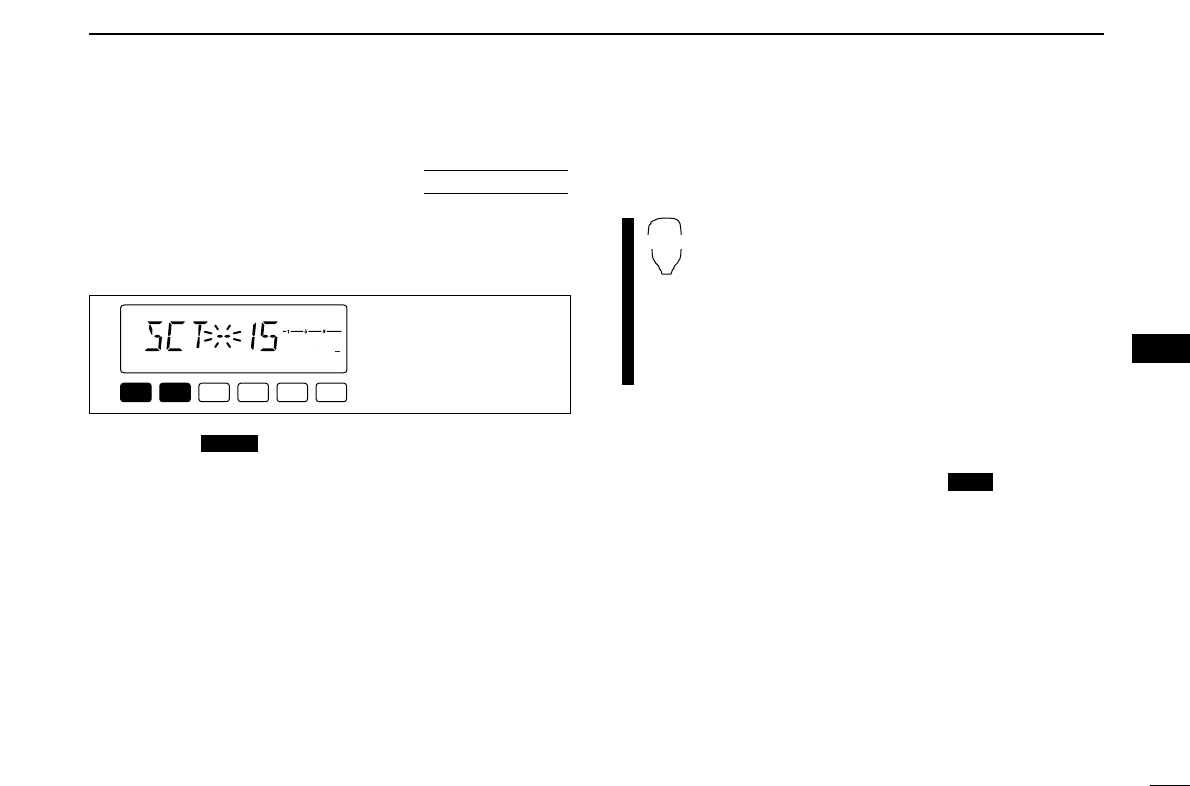
42
7
SCAN OPERATION
7
■Scan resume condition
The scan resume condition can be selected as timer or pause
scan. The selected resume condition is also used for priority
watch. (p. 44)
qPush [SET ] to enter set mode.
wPush [SET] or [MONI] several times until “SCT” or “SCP”
appears as shown above.
• When “d” is displayed in place of the 100 MHz digit, cancel the
DTMF memory encoder in advance. (p. 46)
eRotate [DIAL] to set the desired timer:
• “SCT-15” : Scan pauses 15 sec. while receiving a signal.
• “SCT-10” : Scan pauses 10 sec. while receiving a signal.
• “SCT-5” : Scan pauses 5 sec. while receiving a signal.
• “SCP-2” : Scan pauses until the signal disappears and then
resumes 2 sec. later.
rPush any keys than [SET] or [MONI] to exit set mode.
zPush [
SET
B(D-OFF)] to enter set mode.
xPush [
SET
B(D-OFF)] or [
ENT
C(T-OFF)] several
times until “SCT” or “SCP” appears as shown at
left.
cPush [YY]or [ZZ]to select the scan resume condi-
tion.
• See item eat left for scan resume condition details.
vPush [
CLR
A(MW)] to exit set mode.
☞NOTE:
Set mode cannot be accessed when memory names are
displayed. To set the scan resume condition, return to fre-
quency indication by pushing [MONI ] on the front
panel for 1 sec., or push [FUNC] then [
MONI
1(ANM)] (HM-
133V) to cancel the channel name indication, then set as
described on this page.
ANM
SET
B
LOCK
LOCK
S
E
T
ANM
MONI
DUP
LOW
T-SCAN
TONE
PRIO
M/CALL
SCAN
V/MHz
DIGITAL PRIO AO BUSY
MUTE
NAR
MID
LOW
The display shows that
the scan will resume
15 sec. after it stops.
USING
SET MODE
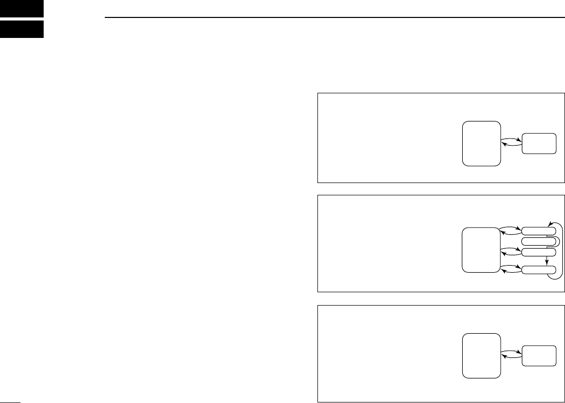
43
PRIORITY WATCH
8
■Priority watch types
Priority watch checks for signals on a VFO frequency every
5 sec. while operating on a memory channel. The transceiver
has 3 priority watch types to suit your needs. You can transmit
on the VFO frequency while the priority watch operates.
The watch resumes according to the selected scan resume
condition. See previous page for details.
☞NOTES:
➧If the pocket beep function is activated, the transceiver
automatically selects the tone squelch function when pri-
ority watch starts.
MEMORY CHANNEL WATCH
While operating on a VFO fre-
quency, priority watch checks for
a signal on the selected memory
channel every 5 sec.
MEMORY SCAN WATCH
While operating on a VFO fre-
quency, priority watch checks for
signals on each memory chan-
nel in sequence.
• The memory skip function is useful
to speed up the scan.
5 sec.
VFO
frequency
50 msec.
Memory
channel
5 sec. 50 msec.
VFO
frequency
SKIP
Mch 1
Mch 2
Mch 3
Mch 199
CALL CHANNEL WATCH
While operating on a VFO fre-
quency, priority watch checks for
signals on the call channel every
5 sec.
5 sec.
VFO
frequency
50 msec.
Call
channel
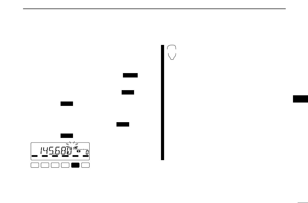
44
8
PRIORITY WATCH
8
■Priority watch operation
qSelect VFO mode; then, set an operating frequency.
wSet the watching channel(s).
For memory channel watch:
Select the desired memory channel.
For memory scan watch:
Select memory mode; then, push [V/MHz ] for
1 sec. to start memory scan.
For call channel watch:
Select the call channel by pushing [M/CALL ] once
or twice.
ePush [M/CALL ] for 1 sec. to start the watch.
• The transceiver checks the memory or call channel every 5 sec.
• The watch resumes according to the selected scan resume con-
dition. (p. 42)
• While the watch is pausing, pushing [M/CALL ] resumes
the watch manually.
rPush [M/CALL ] to stop the watch.
zSelect VFO mode; then, set an operating fre-
quency.
xSet the watching channel(s).
For memory channel watch:
Push [MR/CALL] then [YY]or [ZZ]to select the
desired memory channel.
For memory scan watch:
Push [MR/CALL], then push [
SCAN
2] to start the
memory scan.
For call channel watch:
Push [MR/CALL] for 1 sec. to select the call
channel.
cPush [
PRIO
3(PTT-M)] to start the watch.
• The transceiver checks the memory or call channel
every 5 sec.
• The watch resumes according to the selected scan re-
sume condition. (p. 42)
• To resume the watch manually when paused, push
[
PRIO
3(PTT-M)] or [
CLR
A(MW)].
vTo stop the watch, push [
CLR
A(MW)].
PRIO
3
LOCK
S
E
T
ANM
MONI
DUP
LOW
T-SCAN
TONE
PRIO
M/CALL
SCAN
V/MHz
DIGITAL PRIO AO BUSY
MUTE
NAR
MID
LOW
While pausing or receiving
a signal on the memory or
call channel, “PRIO” blinks.
PRIO
PRIO
PRIO
PRIO
SCAN
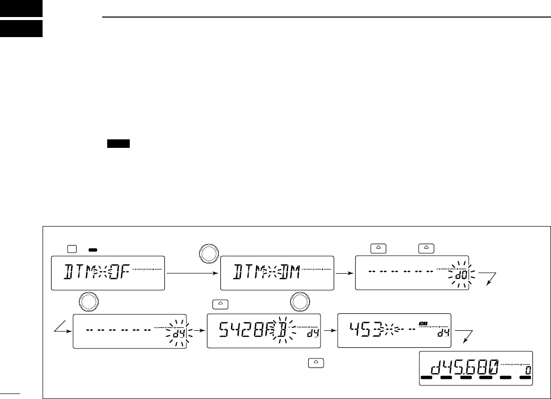
45
DTMF MEMORY ENCODER
9
■Programming a DTMF code
DTMF codes are used for autopatching, controlling other
equipment, etc. The transceiver has 10 DTMF memory chan-
nels (d0–d9) for storage of often-used DTMF codes of up to
24 digits.
qPush [BANK ] for 1 sec. to enter the DTMF setting.
wRotate [DIAL] to turn the DTMF encoder ON.
ePush [SET] or [MONI] to enter the DTMF programming
condition.
• Push [V/MHz] to return to the DTMF setting.
rRotate [DIAL] to select the desired DTMF memory chan-
nel.
• The DTMF memory channel indication blinks.
tPush [SET] or [MONI].
• The first digit blinks.
yRotate [DIAL] to select the desired code.
uPush [MONI] to select the next digit.
• Push [SET] to move the cursor backward.
iRepeat the steps yand uto set the desired DTMF tone
sequence.
• The S/RF indicator shows the digit group. The indication in-
creases every 6 digit.
oPush [V/MHz], then push any other key than [SET],
[MONI] or [V/MHz] to exit DTMF memory programming
condition.
OPT
[EXAMPLE]: Programming “5428AB453” into DTMF memory channel “d4.”
LOCK
S
E
T
ANM
MONI
DUP
LOW
T-SCAN
TONE
PRIO
M/CALL
SCAN
V/MHz
DIGITAL PRIO AO BUSY
MUTE
NAR
MID
LOW
LOCK
S
E
T
ANM
MONI
DUP
LOW
T-SCAN
TONE
PRIO
M/CALL
SCAN
V/MHz
DIGITAL PRIO AO BUSY
MUTE
NAR
MID
LOW
LOCK
S
E
T
ANM
MONI
DUP
LOW
T-SCAN
TONE
PRIO
M/CALL
SCAN
V/MHz
DIGITAL PRIO AO BUSY
MUTE
NAR
MID
LOW
LOCK
S
E
T
ANM
MONI
DUP
LOW
T-SCAN
TONE
PRIO
M/CALL
SCAN
V/MHz
DIGITAL PRIO AO BUSY
MUTE
NAR
MID
LOW
LOCK
S
E
T
ANM
MONI
DUP
LOW
T-SCAN
TONE
PRIO
M/CALL
SCAN
V/MHz
DIGITAL PRIO AO BUSY
MUTE
NAR
MID
LOW
LOCK
S
E
T
ANM
MONI
DUP
LOW
T-SCAN
TONE
PRIO
M/CALL
SCAN
V/MHz
DIGITAL PRIO AO BUSY
MUTE
NAR
MID
LOW
LOCK
S
E
T
ANM
MONI
DUP
LOW
T-SCAN
TONE
PRIO
M/CALL
SCAN
V/MHz
DIGITAL PRIO AO BUSY
MUTE
NAR
MID
LOW
OPT
BANK SET
( ) SET
( )
Push or .
V/MHz
( )
Push , then any other keys
than indicated function keys.
SET
( )
Push then rotate .
Repeat the previous step
until the desired code is entered.
Rotate to turn the DTMF encoder ON.
Rotate .
Push for 1 sec.
46
9
DTMF MEMORY ENCODER
9
■Transmitting a DTMF code
DAutomatic transmission (DTMF memory)
zPush [FUNC] then [
LOW
6(DTMF)] to turn the
DTMF memory encoder ON.
• “d” appears in place of the 100 MHz digit.
xPush [BANK/OPTION] for 1 sec. then
[
SET
B(D-OFF)] to enter the DTMF memory pro-
gramming condition.
cPush [YY]or [ZZ]to select the desired channel.
vPush [PTT] to transmit the selected memory.
• Exit the programming condition automatically.
• Each push of [PTT] transmits the DTMF code.
bPush [FUNC] then [
SET
B(D-OFF)] to cancel the
DTMF memory encoder.
• When the DTMF encoder is turned ON continuously,
each push of the PTT transmits the previously se-
lected DTMF code.
DTransmitting a DTMF memory directly
zPush [FUNC] then [
LOW
6(DTMF)] to turn the
DTMF memory encoder ON.
• “d” appears in place of the 100 MHz digit.
x
Push [DTMF-S] to turn the DTMF memory di-
rect selection ON.
• The function indicator (microphone) lights green.
cPush the desired DTMF channel number.
• “0” to “9” are available for channel numbers.
• The selected DTMF code is automatically transmit-
ted without pushing PTT.
DTransmitting a DTMF memory directly— continued
NOTE: When no DTMF code programmed
channel number is pushed, it transmits previ-
ously transmitted DTMF memory code.
vPush [DTMF-S] again to deactivate the DTMF
memory direct selection.
bPush [FUNC] then [
SET
B(D-OFF)] to cancel
the DTMF memory encoder.
DManual transmission
zDeactivate the DTMF memory encoder by
pushing [FUNC] then [
SET
B(D-OFF)].
x
Push [DTMF-S] to turn the DTMF direct selec-
tion ON.
• The function indicator (microphone) lights green.
cPush one of “A” to “F” keys momentarily, then
push the desired DTMF keys, 0–9 and A to F.
• A: [
CLR
A(MW)] B: [
SET
B(D-OFF)],
C: [
ENT
C(T-OFF)] D: [
SQL
YYD(MUTE)],
E: [MM(TONE-1)] F: [
SQL
ZZ#(16KEY-L)]
• Automatically transmits without pushing PTT.
• The first code, one of “A” to “F,” is not transmitted.
DTMF code transmission starts from the 2nd code.
vPush [DTMF-S] again to deactivate the DTMF
direct selection.
DTMF-S
DTMF-S
DTMF-S
DTMF
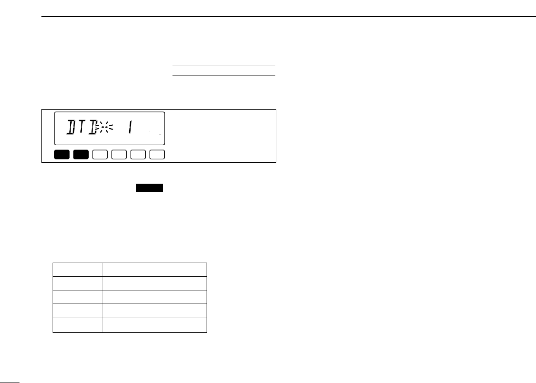
47
9DTMF MEMORY ENCODER
■DTMF speed
The rate at which DTMF memories send individual DTMF
characters can be set to accommodate operating needs.
qPush [PWR] for 1 sec. to turn power OFF.
wWhile pushing [SET ], push [PWR] for 1 sec. to
turn power ON and enter initial set mode.
ePush [SET] or [MONI] several times until “DTD” appears
as shown above.
rRotate [DIAL] to select the desired speed as shown in the
table below.
tPush [PWR] to exit initial set mode.
cps=characters/sec
LOCK
LOCK
S
E
T
ANM
MONI
DUP
LOW
T-SCAN
TONE
PRIO
M/CALL
SCAN
V/MHz
DIGITAL PRIO AO BUSY
MUTE
NAR
MID
LOW
The display shows the
fastest DTMF speed is
selected.
USING
INITIAL SET MODE
DISPLAY INTERVAL SPEED
DTD-- 1 100 msec. 5.0 cps
DTD-- 2 200 msec. 2.5 cps
DTD-- 3 300 msec. 1.6 cps
DTD-- 5 500 msec. 1.0 cps
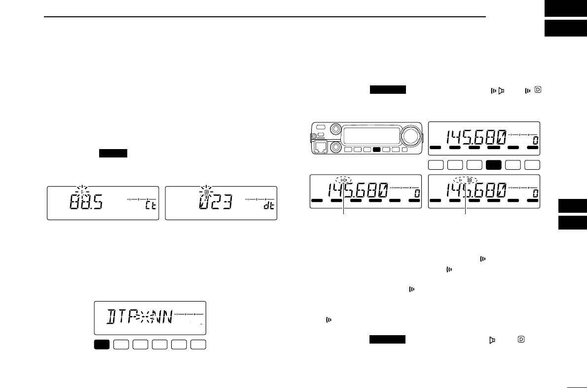
48
10
POCKET BEEP AND TONE SQUELCH
9
10
■Pocket beep operation
This function uses subaudible tones for calling and can be
used as a “common pager” to inform you that someone has
called while you were away from the transceiver.
DWaiting for a call from a specific station
qSet the operating frequency.
wPush [SET ] to enter set mode.
ePush [SET] or [MONI] several times until “Ct” for tone
squelch or “dt” for DTCS squelch appears.
rRotate [DIAL] to select the desired tone squelch frequency
or DTCS code.
tWhen operating the pocket beep function with DTCS
squelch, push [SET] once then rotate [DIAL] to select the
DTCS polarity.
yPush any other key than [SET] or [MONI] to exit set mode.
uPush [TONE ] several times until “ ” or “ ”
are displayed to turn ON the pocket beep with tone
squelch or DTCS squelch, respectively.
iWhen a signal with the matched tone is received, the
transceiver emits beep tones and blinks “ ”.
• Beep tones sound for 30 sec. and “ ” blinks. To stop the beeps
and blinking manually, push any key. When the beep tones are
not stopped manually, “ ” continues flashing until step iis
operated.
oPush [PTT] to answer.
• “ ” disappears and cancels the pocket beep function automati-
cally.
!0 Push [TONE ] several times until “ ” or “ ” dis-
appears to cancel the tone squelch or DTCS squelch func-
tion.
T-SCAN
LOCK
S
E
T
ANM
MONI
DUP
LOW
T-SCAN
TONE
PRIO
M/CALL
SCAN
V/MHz
DIGITAL PRIO AO BUSY
MUTE
NAR
MID
LOW
LOCK
S
E
T
ANM
MONI
DUP
LOW
T-SCAN
TONE
PRIO
M/CALL
SCAN
V/MHz
DIGITAL PRIO AO BUSY
MUTE
NAR
MID
LOW
LOCK
S
E
T
ANM
MONI
DUP
LOW
T-SCAN
TONE
PRIO
M/CALL
SCAN
V/MHz
DIGITAL PRIO AO BUSY
MUTE
NAR
MID
LOW
Appears when the pocket beep
with tone squelch is activated.
Appears when the pocket beep
with DTCS squelch is activated.
T-SCAN
LOCK
S
E
T
ANM
MONI
DUP
LOW
T-SCAN
TONE
PRIO
M/CALL
SCAN
V/MHz
DIGITAL PRIO AO BUSY
MUTE
NAR
MID
LOW
DTCS polarity setting
LOCK
S
E
T
ANM
MONI
DUP
LOW
T-SCAN
TONE
PRIO
M/CALL
SCAN
V/MHz
DIGITAL PRIO AO BUSY
MUTE
NAR
MID
LOW
LOCK
S
E
T
ANM
MONI
DUP
LOW
T-SCAN
TONE
PRIO
M/CALL
SCAN
V/MHz
DIGITAL PRIO AO BUSY
MUTE
NAR
MID
LOW
Tone squelch frequency setting DTCS code setting
LOCK
49
10 POCKET BEEP AND TONE SQUELCH
zSet the operating frequency.
xProgram the CTCSS tone frequency or DTCS
code in set mode.
➥Push [
SET
B(D-OFF)] to enter set mode.
➥Push [
SET
B(D-OFF)] or [
ENT
C(T-OFF)]
several times until “Ct” for tone squelch or
“dt” for DTCS squelch appears.
• “ ” blinks when tone squelch (“Ct”), or “ ”
blinks when DTCS squelch (“dt”) is selected.
➥Push [YY]/[ZZ]to select the desired tone
frequency or DTCS code.
➥Push [
SET
B(D-OFF)] to select “DTP” then
push [YY]/[ZZ]to select the DTCS polarity.
➥Push [
CLR
A(MW)] to exit set mode.
cPush [FUNC] then push [
DUP
+ 8(TSQLSS)]
or [
MID
5(DTCSSS)] to turn ON the pocket
beep with tone squelch or DTCS squelch, re-
spectively.
vWhen a signal with the matched tone is re-
ceived, the transceiver emits beep tones for
30 sec. and blinks “”.
bPush [PTT] to answer or push [
CLR
A(MW)]
to stop the beeps and flashing.
• “ ” disappears and cancels the pocket beep func-
tion automatically.
nTo cancel the tone squelch or DTCS squelch
function, push [FUNC] then [
ENT
C(T-OFF)].
• “ ” or “ ” disappears
DAvailable tone frequency list
NOTE: The transceiver has 50 tone frequencies and con-
sequently their spacing is narrow compared to units having
38 tones. Therefore, some tone frequencies may receive
interference from adjacent tone frequencies.
To prevent interference from adjacent tone frequencies,
using the frequencies as in the following table, is recom-
mended.
DCalling a waiting station using pocket beep
A subaudible tone matched with the station’s CTCSS tone fre-
quency or 3-digit DTCS code with polarity is necessary. Use
the tone squelch on the next page or a subaudible tone en-
coder (pgs. 19, 50)
67.0
69.3
71.9
74.4
88.5
91.5
94.8
97.4
114.8
118.8
123.0
127.3
151.4
156.7
162.2
167.9
203.5
210.7
218.1
225.7
77.0
79.7
82.5
85.4
100.0
103.5
107.2
110.9
131.8
136.5
141.3
146.2
173.8
179.9
186.2
192.8
233.6
241.8
250.3
• Recommended tone frequencies
67.0
69.3
71.9
74.4
77.0
79.7
82.5
85.4
88.5
91.5
94.8
97.4
100.0
103.5
107.2
110.9
114.8
118.8
123.0
127.3
131.8
136.5
141.3
146.2
151.4
156.7
159.8
162.2
165.5
167.9
171.3
173.8
177.3
179.9
183.5
186.2
189.9
192.8
196.6
199.5
203.5
206.5
210.7
218.1
225.7
229.1
233.6
241.8
250.3
254.1
TSQLS
DTCSS
50
10
POCKET BEEP AND TONE SQUELCH
10
■Tone/DTCS squelch operation
The tone or DTCS squelch opens only when receiving a sig-
nal with the same pre-programmed subaudible tone or DTCS
code, respectively.
qSet the operating frequency.
wProgram the CTCSS tone frequency or DTCS code in set
mode.
• See p. 48 for programming details.
ePush [TONE ] several times until “ ” or “ ” ap-
pears in the function display.
• “ ” for tone squelch; “ ” for DTCS squelch operation.
rWhen a signal with the matched tone is received, the
squelch opens and the signal can be heard.
• When the received signal includes an unmatched tone, the
squelch does not open. However, the S/RF indicator shows the
received signal strength.
• To open the squelch manually, push [MONI ].
tOperate the transceiver in the normal way (push [PTT] to
transmit; release [PTT] to receive).
yTo cancel the tone squelch, push [TONE ] sev-
eral times until “ ” or “ ” disappears.
zSet the operating frequency.
xProgram the CTCSS tone frequency or DTCS
code in set mode.
• See p. 49 for programming details.
c
Push [FUNC] then [
SIMP
9(TSQL)] or
[
HIGH
4(DTCS)]
to turn the tone squelch or DTCS
squelch ON.
vWhen a signal with the matched tone is received,
the squelch opens and the signal can be heard.
• When the received signal includes an unmatched
tone, the squelch does not open. However, the S/RF
indicator shows the received signal strength.
• To open the squelch manually, push [
MONI
1(ANM)].
bOperate the transceiver in the normal way (push
[PTT] to transmit; release [PTT] to receive.
nTo cancel the tone squelch, push [FUNC] then
[
ENT
C(T-OFF)].
• “ ” or “ ” disappears
TSQL
DTCS
T-SCAN
ANM
T-SCAN
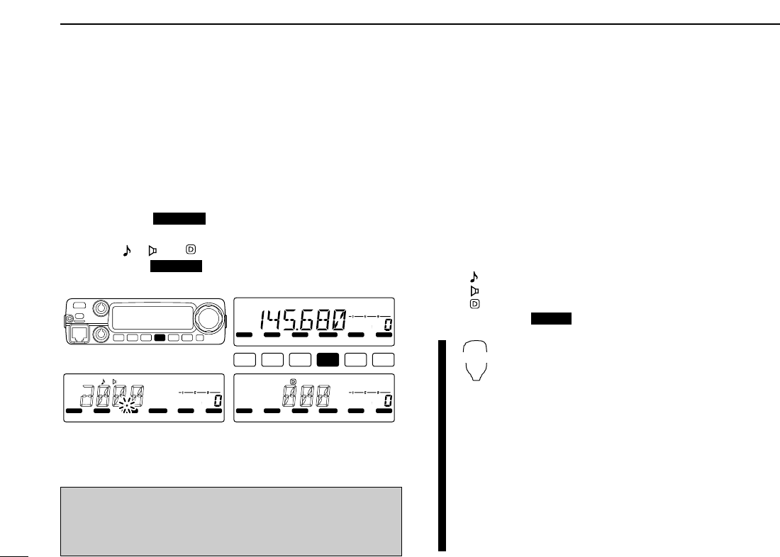
51
10 POCKET BEEP AND TONE SQUELCH
■Tone scan
By monitoring a signal that is being operated with pocket
beep, tone or DTCS squelch function, you can determine the
tone frequency or DTCS code necessary to open a squelch.
qSet the channel to be checked for a tone frequency or
code.
wPush [TONE ] several times to select the tone
condition or type to be scanned.
• One of “ ,” “ ” or “ ” appears
ePush [TONE ] for 1 sec. to start the tone scan.
• To change the scanning direction, rotate [DIAL].
rWhen the CTCSS tone frequency or 3-digit DTCS code is
matched, the squelch opens and the tone frequency is
temporarily programmed into the selected condition such
as memory or call channel.
• The tone scan pauses when a CTCSS tone frequency or 3-digit
DTCS code is detected.
• The decoded CTCSS tone frequency or 3-digit DTCS code is
used for the tone encoder or tone encoder/decoder depending
on the selected tone condition or type in step w.
- No indication : Cannot be used for operation.
- “ ” : CTCSS tone encoder
- “ ” : CTCSS tone encoder/decoder
- “ ” : DTCS tone encoder/decoder
tPush [V/MHz ] to stop the scan.
zSet the channel to be checked for a tone fre-
quency.
xSelects the tone condition or type to be
scanned.
• Push [FUNC] then push; [
DUP
–7(TONE)] for re-
peater tone; [
SIMP
9(TSQL)] for tone squelch;
[
HIGH
4(DTCS)] for DTCS squelch.
cPush [FUNC] then [
SCAN
2(T-SCAN)] to start
the tone scan.
vWhen the tone frequency is matched, the
squelch opens and the tone frequency is pro-
grammed into the selected mode such as
memory or call channel.
bPush [
CLR
A(MW)] to stop the scan.
T-SCAN
SCAN
LOCK
S
E
T
ANM
MONI
DUP
LOW
T-SCAN
TONE
PRIO
M/CALL
SCAN
V/MHz
DIGITAL PRIO AO BUSY
MUTE
NAR
MID
LOW
LOCK
S
E
T
ANM
MONI
DUP
LOW
T-SCAN
TONE
PRIO
M/CALL
SCAN
V/MHz
DIGITAL PRIO AO BUSY
MUTE
NAR
MID
LOW
LOCK
S
E
T
ANM
MONI
DUP
LOW
T-SCAN
TONE
PRIO
M/CALL
SCAN
V/MHz
DIGITAL PRIO AO BUSY
MUTE
NAR
MID
LOW
During CTCSS tone scan During DTCS code scan
T-SCAN
T-SCAN
☞NOTE: The decoded tone frequency is programmed tem-
porarily when a memory or call channel is selected. How-
ever, this will be cleared when the memory/call channel is
re-selected.
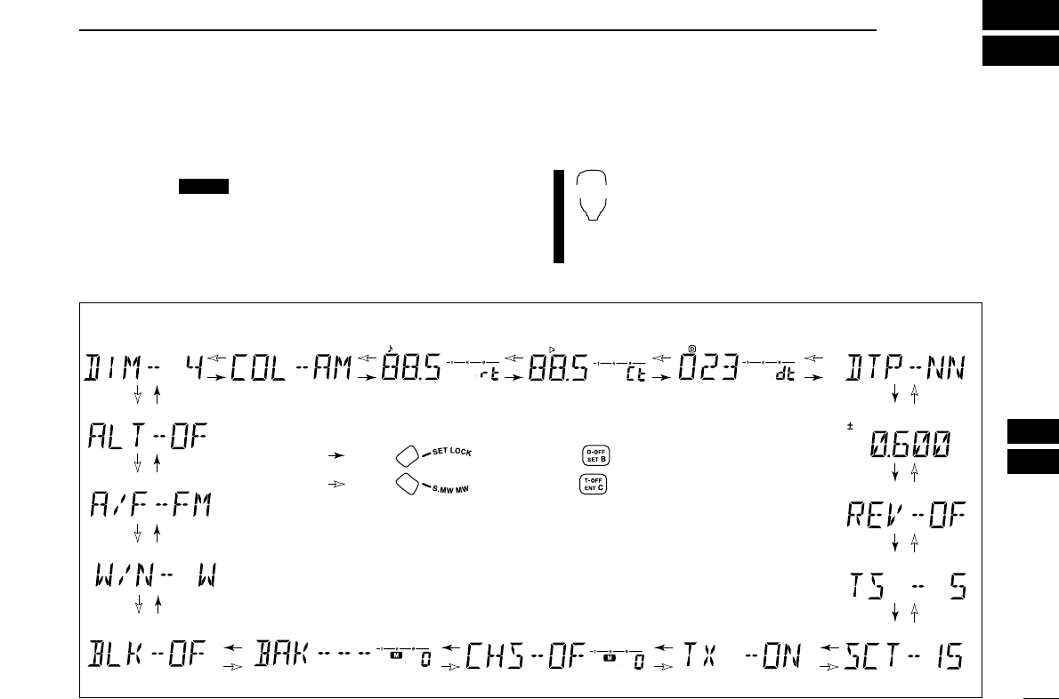
58
12
OTHER FUNCTIONS
11
12
■Set mode
•Set mode operation
qPush [SET ] to enter the set mode.
wPush [SET] or [MONI] to select the desired item.
eRotate [DIAL] to select the condition or value.
rPush any other key than [SET] or [MONI] to exit set mode.
•Set mode items
zPush [
SET
B(D-OFF)] to enter set mode.
xPush [
SET
B(D-OFF)] or [
ENT
C(T-OFF)] to select
the desired item.
cPush [YY]or [ZZ]to select the condition or value.
vPush [
CLR
A(MW)] to exit set mode.
SET
B
LOCK
*Available for USA version only.
†Appears when accessing set mode from VFO mode only.
‡Appears when accessing set mode from memory mode only.
: Push (front panel); or (microphone)
: Push (front panel); or (microphone)
• Weather alert*
• AM/FM mode select*
• Display dimmer • Display color • Repeater tone
frequency
• Tone squelch
frequency • DTCS code • DTCS polarity
• Offset frequency
• Tuning step
• Reverse mode
• Scan resume timer
• Channel skip setting‡
• Bank link function‡• Bank setting‡
• Wide/Nar. setting*
• Transmit permission
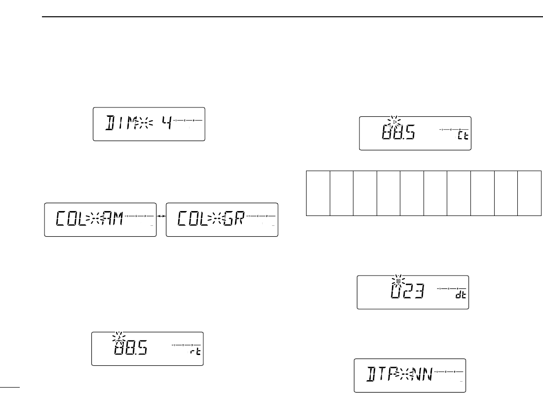
59
12 OTHER FUNCTIONS
DDDisplay dimmer
Adjust to suit lighting conditions.
The levels 1 (dark) to 4 (bright: default) are available.
DDDisplay color
The display color can be set to amber (default) or green.
DDRepeater tone
Sets subaudible tone frequency (encoder only) for repeater
operation. Total of 50 tone frequencies (67.0–254.1 Hz) are
available. (default: 88.5 Hz)
DDTone squelch tone
Sets subaudible tone frequency (both encoder and decoder)
for tone squelch operation. Total of 50 tone frequencies
(67.0–254.1 Hz) are available. (default: 88.5 Hz)
•Available subaudible tone frequencies
DDDTCS code and polarity
Sets DTCS code (both encoder and decoder) for DTCS
squelch operation. Total of 104 codes are available. (default:
023)
DDDTCS polarity
Sets DTCS polarity for transmission and reception from “NN,”
“NR,” “RN,” “RR.” (default: NN)
LOCK
S
E
T
ANM
MONI
DUP
LOW
T-SCAN
TONE
PRIO
M/CALL
SCAN
V/MHz
DIGITAL PRIO AO BUSY
MUTE
NAR
MID
LOW
LOCK
S
E
T
ANM
MONI
DUP
LOW
T-SCAN
TONE
PRIO
M/CALL
SCAN
V/MHz
DIGITAL PRIO AO BUSY
MUTE
NAR
MID
LOW
67.0
69.3
71.9
74.4
77.0
79.7
82.5
85.4
88.5
91.5
94.8
97.4
100.0
103.5
107.2
110.9
114.8
118.8
123.0
127.3
131.8
136.5
141.3
146.2
151.4
156.7
159.8
162.2
165.5
167.9
171.3
173.8
177.3
179.9
183.5
186.2
189.9
192.8
196.6
199.5
203.5
206.5
210.7
218.1
225.7
229.1
233.6
241.8
250.3
254.1
LOCK
S
E
T
ANM
MONI
DUP
LOW
T-SCAN
TONE
PRIO
M/CALL
SCAN
V/MHz
DIGITAL PRIO AO BUSY
MUTE
NAR
MID
LOW
LOCK
S
E
T
ANM
MONI
DUP
LOW
T-SCAN
TONE
PRIO
M/CALL
SCAN
V/MHz
DIGITAL PRIO AO BUSY
MUTE
NAR
MID
LOW
LOCK
S
E
T
ANM
MONI
DUP
LOW
T-SCAN
TONE
PRIO
M/CALL
SCAN
V/MHz
DIGITAL PRIO AO BUSY
MUTE
NAR
MID
LOW
LOCK
S
E
T
ANM
MONI
DUP
LOW
T-SCAN
TONE
PRIO
M/CALL
SCAN
V/MHz
DIGITAL PRIO AO BUSY
MUTE
NAR
MID
LOW
Amber setting (default) Green setting
LOCK
S
E
T
ANM
MONI
DUP
LOW
T-SCAN
TONE
PRIO
M/CALL
SCAN
V/MHz
DIGITAL PRIO AO BUSY
MUTE
NAR
MID
LOW
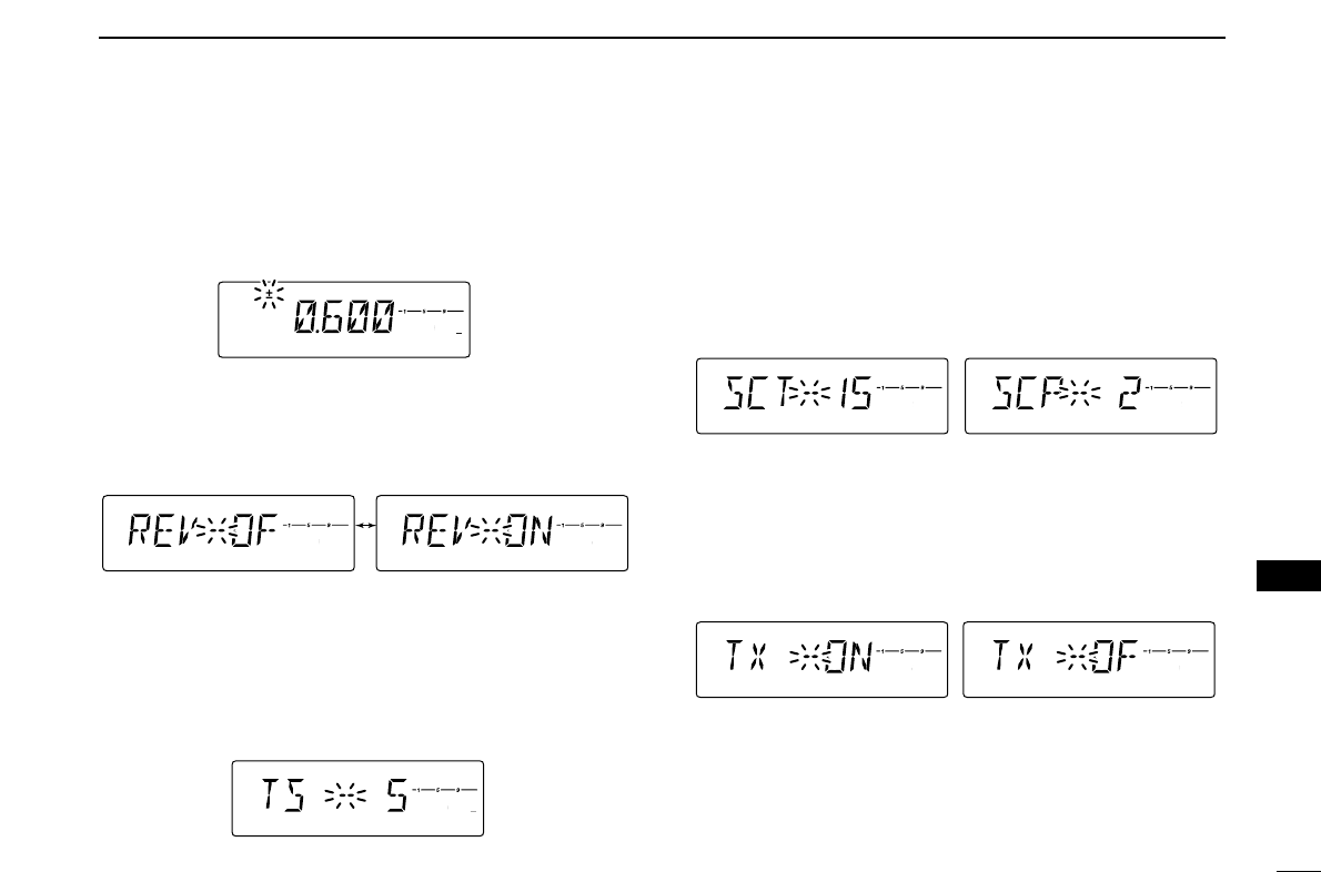
60
12
OTHER FUNCTIONS
12
DDOffset frequency
Sets the duplex offset frequency within 0 to 20 MHz range.
During duplex (repeater) operation, transmit frequency (or re-
ceive when reverse function is set to ON) shifts the set fre-
quency. (default value may differ depending on versions)
DDReverse mode
Sets the reverse function ON and OFF (default).
DDTuning step
Selects tuning step from 5 (default), 10, 12.5, 15, 20, 25, 30
and 50 kHz for [DIAL] or [Y]/[Z] operation.
DDScan resume timer
Selects scan resume timer from SCT-15 (default), SCT-10,
SCT-5 and SCP-2.
• SCT-15/10/5 : Scan pauses for 15/10/5 sec., then re-
sumes.
• SCP-2 : Pause on a signal until signal disap-
pears, then resumes 2 sec. after the sig-
nal disappears.
DDTransmit permission
Turns transmission permission ON and OFF. This function
can be set for each memory, call channel and VFO, indepen-
dently.
LOCK
S
E
T
ANM
MONI
DUP
LOW
T-SCAN
TONE
PRIO
M/CALL
SCAN
V/MHz
DIGITAL PRIO AO BUSY
MUTE
NAR
MID
LOW
LOCK
S
E
T
ANM
MONI
DUP
LOW
T-SCAN
TONE
PRIO
M/CALL
SCAN
V/MHz
DIGITAL PRIO AO BUSY
MUTE
NAR
MID
LOW
Transmission is permitted.
(default)
Transmission is inhibited.
LOCK
S
E
T
ANM
MONI
DUP
LOW
T-SCAN
TONE
PRIO
M/CALL
SCAN
V/MHz
DIGITAL PRIO AO BUSY
MUTE
NAR
MID
LOW
LOCK
S
E
T
ANM
MONI
DUP
LOW
T-SCAN
TONE
PRIO
M/CALL
SCAN
V/MHz
DIGITAL PRIO AO BUSY
MUTE
NAR
MID
LOW
LOCK
S
E
T
ANM
MONI
DUP
LOW
T-SCAN
TONE
PRIO
M/CALL
SCAN
V/MHz
DIGITAL PRIO AO BUSY
MUTE
NAR
MID
LOW
LOCK
S
E
T
ANM
MONI
DUP
LOW
T-SCAN
TONE
PRIO
M/CALL
SCAN
V/MHz
DIGITAL PRIO AO BUSY
MUTE
NAR
MID
LOW
LOCK
S
E
T
ANM
MONI
DUP
LOW
T-SCAN
TONE
PRIO
M/CALL
SCAN
V/MHz
DIGITAL PRIO AO BUSY
MUTE
NAR
MID
LOW
Reverse function OFF (default) Reverse function ON
LOCK
S
E
T
ANM
MONI
DUP
LOW
T-SCAN
TONE
PRIO
M/CALL
SCAN
V/MHz
DIGITAL PRIO AO BUSY
MUTE
NAR
MID
LOW
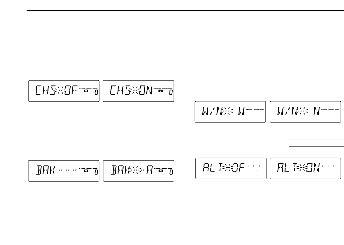
61
12 OTHER FUNCTIONS
DDChannel skip setting
Sets channel skip setting from ON and OFF for memory skip
scan operation.
This item appears when set mode is accessed from memory
mode only.
DDMemory bank setting
Sets the desired memory bank (A to J and OFF) to assign the
reguler memory channels.
This item appears when set mode is accessed from memory
mode only.
DDWide/Narrow setting
Sets both the transmission and reception passband width
from wide and narrow.
When narrow is set, the transmission deviation and reception
passband width become half of the wide setting (approx.).
This setting can be set for each memory, call and VFO inde-
pendently.
This item appears in some USA versions only.
DDWeather alert function
Turns weather alert function ON and OFF.
LOCK
S
E
T
ANM
MONI
DUP
LOW
T-SCAN
TONE
PRIO
M/CALL
SCAN
V/MHz
DIGITAL PRIO AO BUSY
MUTE
NAR
MID
LOW
LOCK
S
E
T
ANM
MONI
DUP
LOW
T-SCAN
TONE
PRIO
M/CALL
SCAN
V/MHz
DIGITAL PRIO AO BUSY
MUTE
NAR
MID
LOW
Weather alert OFF (default) Weather alert ON
U.S.A. versions only
LOCK
S
E
T
ANM
MONI
DUP
LOW
T-SCAN
TONE
PRIO
M/CALL
SCAN
V/MHz
DIGITAL PRIO AO BUSY
MUTE
NAR
MID
LOW
LOCK
S
E
T
ANM
MONI
DUP
LOW
T-SCAN
TONE
PRIO
M/CALL
SCAN
V/MHz
DIGITAL PRIO AO BUSY
MUTE
NAR
MID
LOW
Wide setting (default) Narrow setting
LOCK
S
E
T
ANM
MONI
DUP
LOW
T-SCAN
TONE
PRIO
M/CALL
SCAN
V/MHz
DIGITAL PRIO AO BUSY
MUTE
NAR
MID
LOW
LOCK
S
E
T
ANM
MONI
DUP
LOW
T-SCAN
TONE
PRIO
M/CALL
SCAN
V/MHz
DIGITAL PRIO AO BUSY
MUTE
NAR
MID
LOW
LOCK
S
E
T
ANM
MONI
DUP
LOW
T-SCAN
TONE
PRIO
M/CALL
SCAN
V/MHz
DIGITAL PRIO AO BUSY
MUTE
NAR
MID
LOW
LOCK
S
E
T
ANM
MONI
DUP
LOW
T-SCAN
TONE
PRIO
M/CALL
SCAN
V/MHz
DIGITAL PRIO AO BUSY
MUTE
NAR
MID
LOW
Scans the memory channel.
(does not skip; default)
Does not scan the memory
channel (skips).
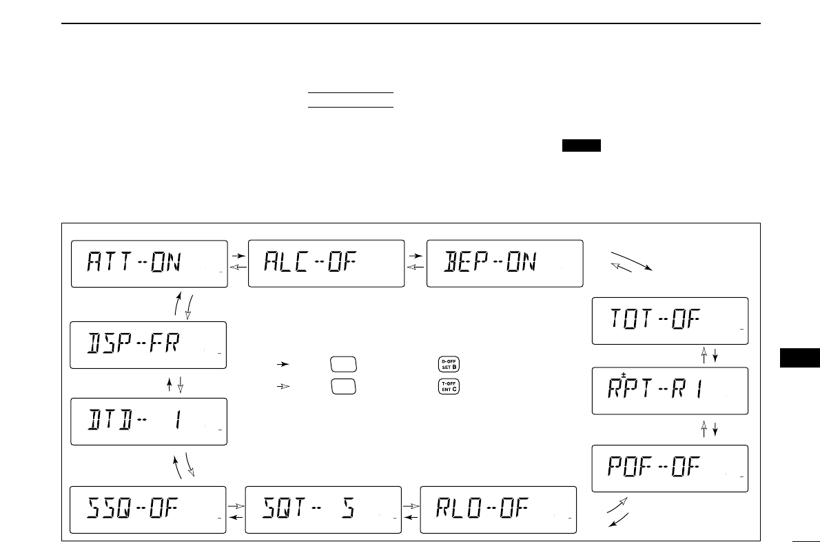
62
12
OTHER FUNCTIONS
12
■Initial set mode
The initial set mode is accessed at power ON and al-
lows you to set seldom-changed settings. In this way,
you can “customize” transceiver operations to suit your
preference and operating style.
•Initial set mode items
DDEntering initial set mode
qWhile pushing [SET ], push [PWR] for 1 sec. to
enter initial set mode.
wPush [SET] or [MONI] to select the desired item.
eRotate [DIAL] to select the condition or value.
rPush [PWR] to exit initial set mode.
LOCK
AT
POWER ON
LOCK
S
E
T
ANM
MONI
DUP
LOW
T-SCAN
TONE
PRIO
M/CALL
SCAN
V/MHz
DIGITAL PRIO AO BUSY
MUTE
NAR
MID
LOW
LOCK
S
E
T
ANM
MONI
DUP
LOW
T-SCAN
TONE
PRIO
M/CALL
SCAN
V/MHz
DIGITAL PRIO AO BUSY
MUTE
NAR
MID
LOW
LOCK
S
E
T
ANM
MONI
DUP
LOW
T-SCAN
TONE
PRIO
M/CALL
SCAN
V/MHz
DIGITAL PRIO AO BUSY
MUTE
NAR
MID
LOW
LOCK
S
E
T
ANM
MONI
DUP
LOW
T-SCAN
TONE
PRIO
M/CALL
SCAN
V/MHz
DIGITAL PRIO AO BUSY
MUTE
NAR
MID
LOW
LOCK
S
E
T
ANM
MONI
DUP
LOW
T-SCAN
TONE
PRIO
M/CALL
SCAN
V/MHz
DIGITAL PRIO AO BUSY
MUTE
NAR
MID
LOW
LOCK
S
E
T
ANM
MONI
DUP
LOW
T-SCAN
TONE
PRIO
M/CALL
SCAN
V/MHz
DIGITAL PRIO AO BUSY
MUTE
NAR
MID
LOW
LOCK
S
E
T
ANM
MONI
DUP
LOW
T-SCAN
TONE
PRIO
M/CALL
SCAN
V/MHz
DIGITAL PRIO AO BUSY
MUTE
NAR
MID
LOW
LOCK
S
E
T
ANM
MONI
DUP
LOW
T-SCAN
TONE
PRIO
M/CALL
SCAN
V/MHz
DIGITAL PRIO AO BUSY
MUTE
NAR
MID
LOW
LOCK
S
E
T
ANM
MONI
DUP
LOW
T-SCAN
TONE
PRIO
M/CALL
SCAN
V/MHz
DIGITAL PRIO AO BUSY
MUTE
NAR
MID
LOW
LOCK
S
E
T
ANM
MONI
DUP
LOW
T-SCAN
TONE
PRIO
M/CALL
SCAN
V/MHz
DIGITAL PRIO AO BUSY
MUTE
NAR
MID
LOW
LOCK
S
E
T
ANM
MONI
DUP
LOW
T-SCAN
TONE
PRIO
M/CALL
SCAN
V/MHz
DIGITAL PRIO AO BUSY
MUTE
NAR
MID
LOW
: Push
SET
LOCK
(front panel); or (microphone)
: Push
*Available in USA version only.
S.MW
MW
(front panel); or (microphone)
• Key-touch beep• ALC setting
• Time-out timer
• Auto repeater*
• Auto power OFF
• Repeater lockout• Squelch delay• S-meter squelch
• DTMF speed
• Display type
• Squelch attenuator
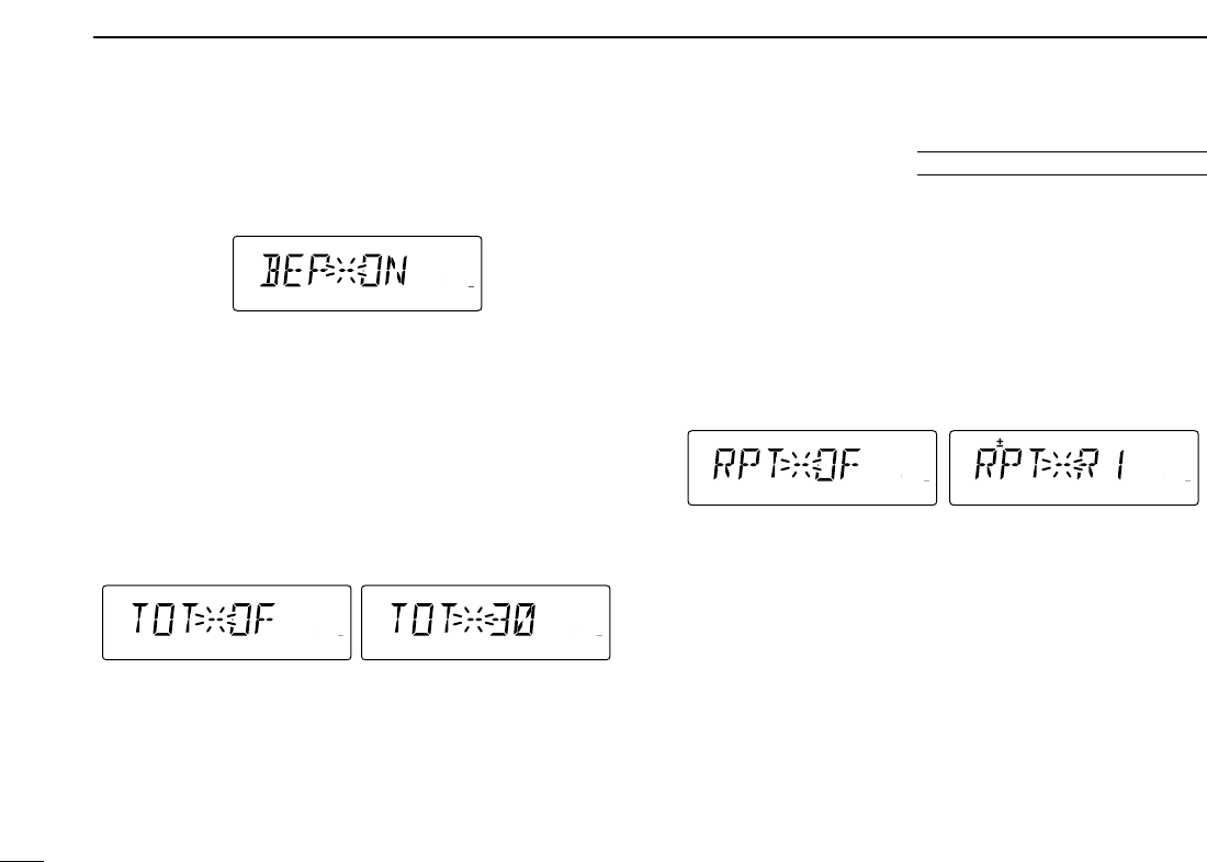
63
12 OTHER FUNCTIONS
DDKey-touch beep
The key-touch beep can be turned OFF for silent operation.
(default: ON)
DDTime-out timer
To prevent accidental prolonged transmission, etc., the trans-
ceiver has a time-out timer. This function cuts a transmission
OFF after 1–30 min. of continuous transmission. This timer
can be cancelled.
• TOT-OF : The time-out timer is turned OFF. (default)
• TOT-1–30 : The transmission is cut OFF after the set
period elapses.
DDAuto repeater
The auto repeater function automatically turns ON or OFF the
duplex operation with a specified shift direction and tone en-
coder, when the operating frequency falls within or outside of
145.200–145.495 MHz, 146.610–146.995 MHz and
147.000–147.395 MHz range. The offset and repeater tone
frequencies are not changed by the auto repeater function,
reset these frequencies, if necessary.
• OF : The auto repeater function is turned OFF.
• R1 : Activates for duplex only. (default)
• R2 : Activates for duplex and tone.
LOCK
S
E
T
ANM
MONI
DUP
LOW
T-SCAN
TONE
PRIO
M/CALL
SCAN
V/MHz
DIGITAL PRIO AO BUSY
MUTE
NAR
MID
LOW
LOCK
S
E
T
ANM
MONI
DUP
LOW
T-SCAN
TONE
PRIO
M/CALL
SCAN
V/MHz
DIGITAL PRIO AO BUSY
MUTE
NAR
MID
LOW
U.S.A. version only
LOCK
S
E
T
ANM
MONI
DUP
LOW
T-SCAN
TONE
PRIO
M/CALL
SCAN
V/MHz
DIGITAL PRIO AO BUSY
MUTE
NAR
MID
LOW
LOCK
S
E
T
ANM
MONI
DUP
LOW
T-SCAN
TONE
PRIO
M/CALL
SCAN
V/MHz
DIGITAL PRIO AO BUSY
MUTE
NAR
MID
LOW
LOCK
S
E
T
ANM
MONI
DUP
LOW
T-SCAN
TONE
PRIO
M/CALL
SCAN
V/MHz
DIGITAL PRIO AO BUSY
MUTE
NAR
MID
LOW
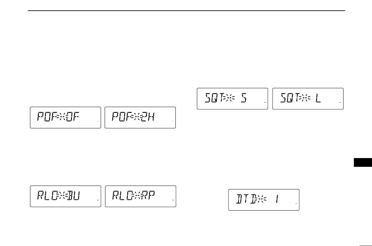
64
12
OTHER FUNCTIONS
12
DDAuto power OFF
The transceiver can be set to automatically turn OFF after a
specified period with a beep when no key operations are per-
formed.
30 min., 1 hour, 2 hours and OFF (default) can be specified.
The specified period is retained even when the transceiver is
turned OFF by the auto power OFF function. To cancel the
function, select “OF” in this set mode.
DDRepeater lockout
Selects lockout type from repeater, busy and OFF.
• OF : No lockout is activated. (default)
• RP : The repeater lockout is turned ON.
• BU : The busy lockout is turned ON.
DDSquelch delay
Selects squelch delay from short and long to prevent re-
peated opening and closing of the squelch during reception
of the same signal.
• S : Short squelch delay. (default)
• L : Long squelch delay
DDDTMF speed
The rate at which DTMF memories send individual DTMF
characters can be set to accommodate operating needs.
• 1 : 100 msec. interval; 5.0 cps speed (default)
• 2 : 200 msec. interval; 2.5 cps speed
• 3 : 300 msec. interval; 1.6 cps speed
• 5 : 500 msec. interval; 1.0 cps speed
LOCK
S
E
T
ANM
MONI
DUP
LOW
T-SCAN
TONE
PRIO
M/CALL
SCAN
V/MHz
DIGITAL PRIO AO BUSY
MUTE
NAR
MID
LOW
LOCK
S
E
T
ANM
MONI
DUP
LOW
T-SCAN
TONE
PRIO
M/CALL
SCAN
V/MHz
DIGITAL PRIO AO BUSY
MUTE
NAR
MID
LOW
LOCK
S
E
T
ANM
MONI
DUP
LOW
T-SCAN
TONE
PRIO
M/CALL
SCAN
V/MHz
DIGITAL PRIO AO BUSY
MUTE
NAR
MID
LOW
Short squelch delay setting Long squelch delay setting
LOCK
S
E
T
ANM
MONI
DUP
LOW
T-SCAN
TONE
PRIO
M/CALL
SCAN
V/MHz
DIGITAL PRIO AO BUSY
MUTE
NAR
MID
LOW
LOCK
S
E
T
ANM
MONI
DUP
LOW
T-SCAN
TONE
PRIO
M/CALL
SCAN
V/MHz
DIGITAL PRIO AO BUSY
MUTE
NAR
MID
LOW
Busy lock-out setting Repeater lock-out setting
LOCK
S
E
T
ANM
MONI
DUP
LOW
T-SCAN
TONE
PRIO
M/CALL
SCAN
V/MHz
DIGITAL PRIO AO BUSY
MUTE
NAR
MID
LOW
LOCK
S
E
T
ANM
MONI
DUP
LOW
T-SCAN
TONE
PRIO
M/CALL
SCAN
V/MHz
DIGITAL PRIO AO BUSY
MUTE
NAR
MID
LOW
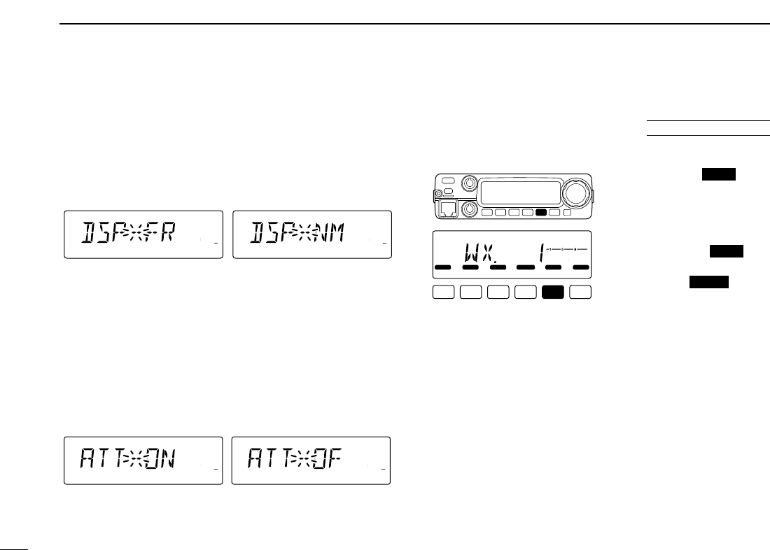
65
12 OTHER FUNCTIONS
DDDisplay type
Selects LCD indication type from frequency, channel number
and channel names.
• FR : Shows frequency (default)
• CH : Shows channel number*
• NM : Shows channel names
*Programmed memory channels only can be selected.
DDSquelch attenuator
Turns the squelch attenuator function ON and OFF.
• ON : The squelch attenuator activates when [SQL]
control is set between 12 o’clock and fully
clockwise position. (default)
• OF : The squelch attenuator does not function.
■Weather channel operation
DDWeather channel selection
qPush [M/CALL ] sev-
eral times to select weather
channel group.
wRotate [DIAL] to select the
desired weather channel.
ePush [M/CALL ] to
select memory mode, or
push [V/MHz ] to se-
lect VFO mode.
SCAN
PRIO
PRIO
LOCK
S
E
T
ANM
MONI
DUP
LOW
T-SCAN
TONE
PRIO
M/CALL
SCAN
V/MHz
DIGITAL PRIO AO BUSY
MUTE
NAR
MID
LOW
U.S.A. versions only
LOCK
S
E
T
ANM
MONI
DUP
LOW
T-SCAN
TONE
PRIO
M/CALL
SCAN
V/MHz
DIGITAL PRIO AO BUSY
MUTE
NAR
MID
LOW
LOCK
S
E
T
ANM
MONI
DUP
LOW
T-SCAN
TONE
PRIO
M/CALL
SCAN
V/MHz
DIGITAL PRIO AO BUSY
MUTE
NAR
MID
LOW
LOCK
S
E
T
ANM
MONI
DUP
LOW
T-SCAN
TONE
PRIO
M/CALL
SCAN
V/MHz
DIGITAL PRIO AO BUSY
MUTE
NAR
MID
LOW
LOCK
S
E
T
ANM
MONI
DUP
LOW
T-SCAN
TONE
PRIO
M/CALL
SCAN
V/MHz
DIGITAL PRIO AO BUSY
MUTE
NAR
MID
LOW
Frequency indication setting Memory channel name
indication setting
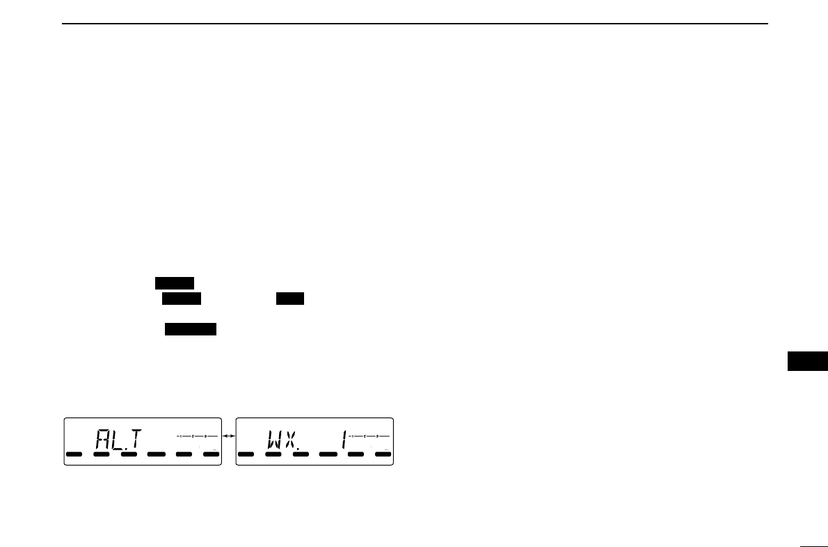
66
12
OTHER FUNCTIONS
12
DDWeather alert function
NOAA broadcast stations transmit weather alert tones before
important weather announcements. When the weather alert
function is turned ON, the selected weather channel is moni-
tored each 5 sec. for the announcement. When the alert sig-
nal is detected, the “AL.T” and the WX channel are displayed
alternately and sounds a beep tone until the transceiver is op-
erated. The previously selected (used) weather channel is
checked periodically during standby or while scanning.
qSelect the desired weather channel.
wTurn the weather alert function ON in set mode.
➥Push [SET ] to enter set mode.
➥Push [SET ] or [S.MW ] to select the
weather alert item, then rotate [DIAL] to set ON.
➥Push [TONE ] to exit set mode.
eSets the desired stand-by condition.
• Selects VFO, memory or call channel.
• Scan or priority watch operation can also be selected.
rWhen the alert is detected, a beep sounds and the follow-
ing indication will be displayed.
tTurn the weather alert function OFF in set mode.
LOCK
S
E
T
ANM
MONI
DUP
LOW
T-SCAN
TONE
PRIO
M/CALL
SCAN
V/MHz
DIGITAL PRIO AO BUSY
MUTE
NAR
MID
LOW
LOCK
S
E
T
ANM
MONI
DUP
LOW
T-SCAN
TONE
PRIO
M/CALL
SCAN
V/MHz
DIGITAL PRIO AO BUSY
MUTE
NAR
MID
LOW
Shows above indications alternately.
T-SCAN
MWLOCK
LOCK
☞NOTE: While receiving a signal (on a frequency other than
the weather alert ON frequency), the receiving signal or
audio will be interrupted momentarily every 5 sec. (approx.)
in case the alert function is turned ON. This symptom is
caused by the WX alert function. To cancel these symp-
toms, set the weather alert item OFF in set mode.

67
12 OTHER FUNCTIONS
■Microphone keys
The supplied HM-133V’s (optional for some versions) [F-1]
and [F-2] keys memorize the transceiver conditions.
The [UP]/[DN] keys of the standard or an optional micro-
phone (other than the HM-133V) can be assigned functions
like the function keys on the transceiver’s front panel.
DD[F-1]/[F-2] keys on HM-133V
The following conditions can be memorized into [F-1] and
[F-2] keys, independently.
• Operating frequency
• Repeater setting (offset direction and frequency, tone
ON/OFF and frequency)
• Tone/DTCS squelch (ON/OFF, frequency/code and polarity)
• Transmit output power selection
• Set mode settings
• Initial set mode settings (except display type item)
➥Programming the condition
Set the desired contents of each condition,
then push [F-1]/[F-2] for 1 sec.
• 3 beeps sound.
➥Re-calling the condition
Push [F-1]/[F-2] momentarily.
DD[UP]/[DN] keys on a microphones
(other than HM-133V)
The following functions are assigned to the [UP]/[DN] keys
on the other microphones (HM-118N/TAN, etc.) when first ap-
plying power.
[UP] : channel up; push and hold to start scan, push again
to stop scan.
[DN] : channel down; push and hold to start scan, push
again to stop scan.
➥Assigning a function
qTurn the power OFF.
wWhile pushing the desired key on the transceiver and one
of either [UP]/[DN] keys on the microphone, turn the
power ON.
• The function is programmed into the key.
➥Clearing an assignment
qTurn the power OFF.
wWhile pushing the desired [UP] or [DN] key on the micro-
phone, turn the power ON.
AT
POWER ON
[F-1]/[F-2]
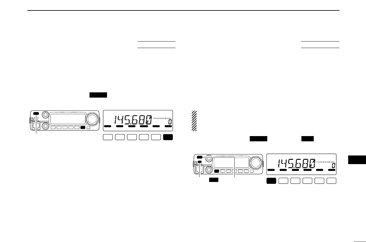
68
12
OTHER FUNCTIONS
12
■Partial reset
If you want to initialize the operating conditions (VFO fre-
quency, VFO settings, set mode contents) without clearing
the memory contents, a partial resetting function is available
for the transceiver.
➥Turn power OFF, if transeciver is powered ON.
➥While pushing [V/MHz ], turn the power ON to par-
tially reset the transceiver.
■All reset
The function display may occasionally display erroneous in-
formation (e.g. when first applying power). This may be
caused externally by static electricity or by other factors.
If this problem occurs, turn power OFF. After waiting a few
seconds, turn power ON again. If the problem persists, per-
form the following procedure.
• Partial resetting is also available. See left for details.
IMPORTANT!:
Resetting the transceiver CLEARS all memory information
and initializes all values in the transceiver.
➥While pushing [SET ] and [S.MW ], turn the
power ON to reset the CPU.
LOCK
S
E
T
ANM
MONI
DUP
LOW
T-SCAN
TONE
PRIO
M/CALL
SCAN
V/MHz
DIGITAL PRIO AO BUSY
MUTE
NAR
MID
LOW
[PWR]
[S.MW MW]
MWLOCK
AT
POWER ON
LOCK
S
E
T
ANM
MONI
DUP
LOW
T-SCAN
TONE
PRIO
M/CALL
SCAN
V/MHz
DIGITAL PRIO AO BUSY
MUTE
NAR
MID
LOW
[PWR]
SCAN
AT
POWER ON
1-1-32 Kamiminami, Hirano-ku, Osaka 547-0003, Japan
A-6???H-1EX
Printed in Japan
©2003 Icom Inc.