ICOM orporated 269900 Amateur UHF Scanning Receiver User Manual
ICOM Incorporated Amateur UHF Scanning Receiver
UserManual.wiki
>
ICOM orporated
>
269900 User Manual
User Manual
Navigation menu
Upload a User Manual
Namespaces
Wiki Guide
HTML
PDF
Info
Views
User Manual
Discussion / Help
Navigation
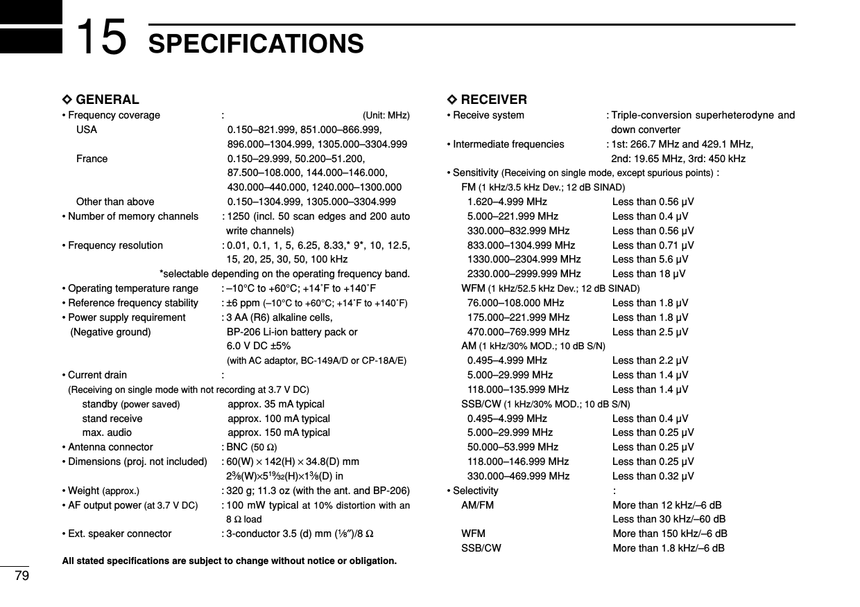
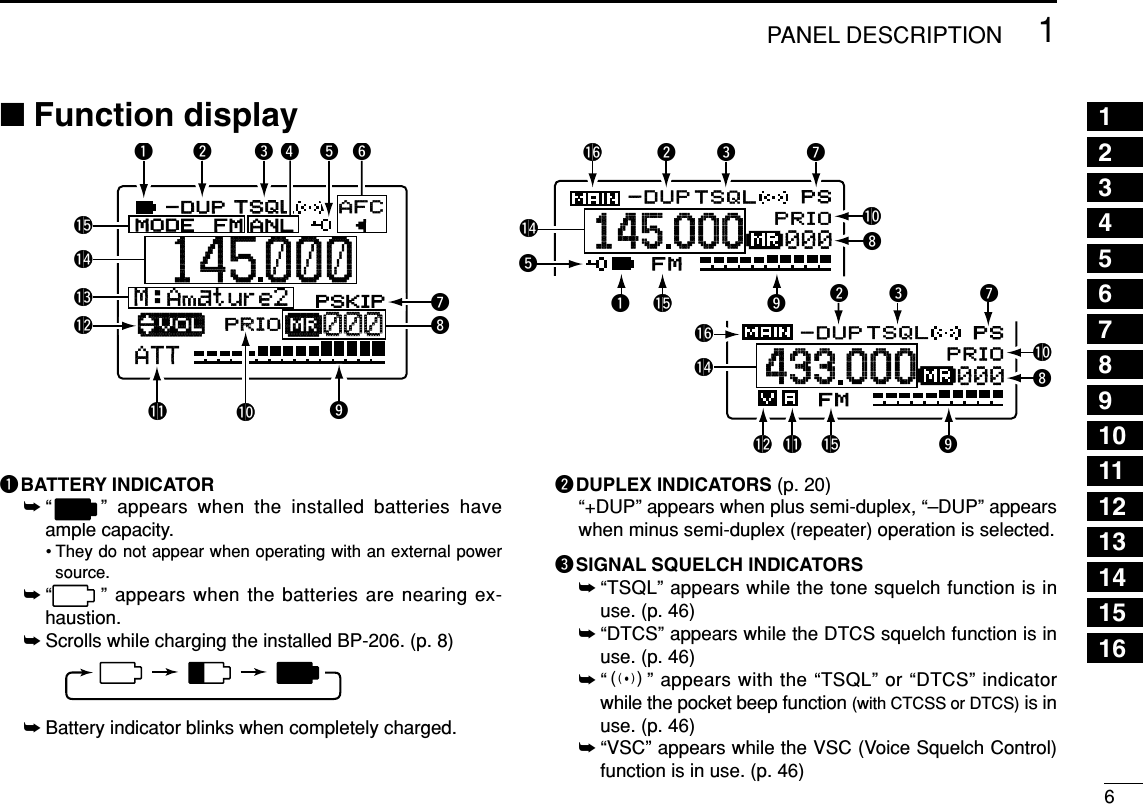
![ivTABLE OF CONTENTS 123456789101112131415FOREWORD .................................................. iIMPORTANT .................................................. iEXPLICIT DEFINITIONS ................................ iPRECAUTION ............................................... iiSUPPLIED ACCESSORIES ......................... iiiOPERATING THEORY ................................. iiiOPERATING NOTES ................................... iiiTABLE OF CONTENTS ................................ ivQUICK REFERENCE GUIDE .................. I–VI■Preparation ............................................. I1 PANEL DESCRIPTION ........................ 1–7■Front, top and side panels .................... 1■Function display .................................... 62 BATTERY CHARGING ...................... 8–10■Battery installation ................................. 8■Caution .................................................. 9■Battery charging .................................... 93 FREQUENCY AND CHANNEL SETTING.......................................................... 11–16■Mode selection..................................... 11■Operating band selection..................... 12■Setting a tuning step............................ 14■Setting a frequency.............................. 14■Selecting a memory channel ............... 10■Receive mode selection ...................... 16■Lock function ....................................... 164 BASIC OPERATION ........................ 17–23■Receiving............................................. 17■Setting audio volume ........................... 17■Squelch level setting............................ 18■Monitor function ................................... 18■Attenuator function .............................. 19■RF gain ................................................ 19■Duplex operation ................................. 20■AFC function........................................ 21■NB/ANL functions ................................ 21■Band scope.......................................... 22■[DIAL] function assignment.................. 235 DUALWATCH OPERATION ............ 24–25■Setting audio volume ........................... 24■Squelch level setting............................ 24■Main band selection............................. 25■Band exchange.................................... 256 MEMORY CHANNELS ..................... 26–33■General description ............................. 26■Memory channel programming............ 26■Memory bank setting ........................... 27■Memory bank selection........................ 28■Programming memory/bank name ...... 29■Selecting memory/bank name indication..... 30■Copying memory contents................... 31■Memory clearing .................................. 32■Erasing/transferring bank contents...... 337 SCAN OPERATION ......................... 34–41■Scan types........................................... 34■Full/band/programmed scan................ 35■Scan edges programming ................... 36■Memory/bank/all bank scan................. 37■Auto-memory write scan...................... 38■Skip channel/frequency setting............ 39■Scan resume condition ........................ 407 PRIORITY WATCH .......................... 42–44■Priority watch types ............................. 42■Priority watch operation ....................... 439 COMFORTABLE RECEIVING.......... 45–48■Tone/DTCS squelch operation............. 45■Tone squelch frequency/DTCS code set-ting....................................................... 46■DTCS polarity setting........................... 47■Tone scan ............................................ 4810 SET MODE ...................................... 49–59■General................................................ 49■Set mode items.................................... 5011 OTHER FUNCTIONS ....................... 60–67■Antenna selection ................................ 60■Weather channel operation ................. 61■Data cloning ........................................ 62■Auto power-off function........................ 63■IC recorder........................................... 64■Partial reset ......................................... 67■All reset ............................................... 6812 CONTROL COMMAND ................... 68–69■General................................................ 68■Data format.......................................... 68■Command table ................................... 6813 FREQUENCY TABLE ...................... 70–61■TV channels......................................... 70■VHF marine channels .......................... 73■Weather channels................................ 73■Other communications in the USA ...... 74■Other communications— other countries............................................................. 7614 MAINTENANCE ..................................... 78■Troubleshooting ................................... 7815 SPECIFICATIONS ................................. 7916 OPTIONS ............................................... 8016](https://usermanual.wiki/ICOM-orporated/269900/User-Guide-409586-Page-5.png)
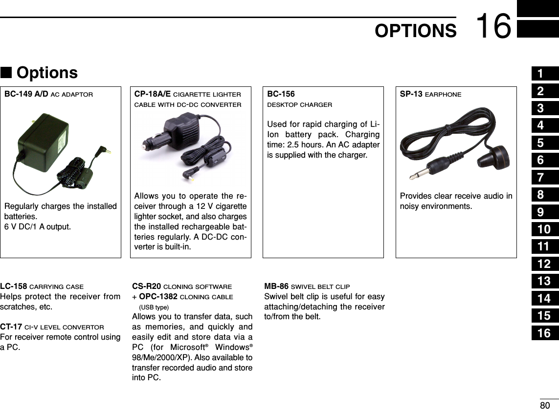
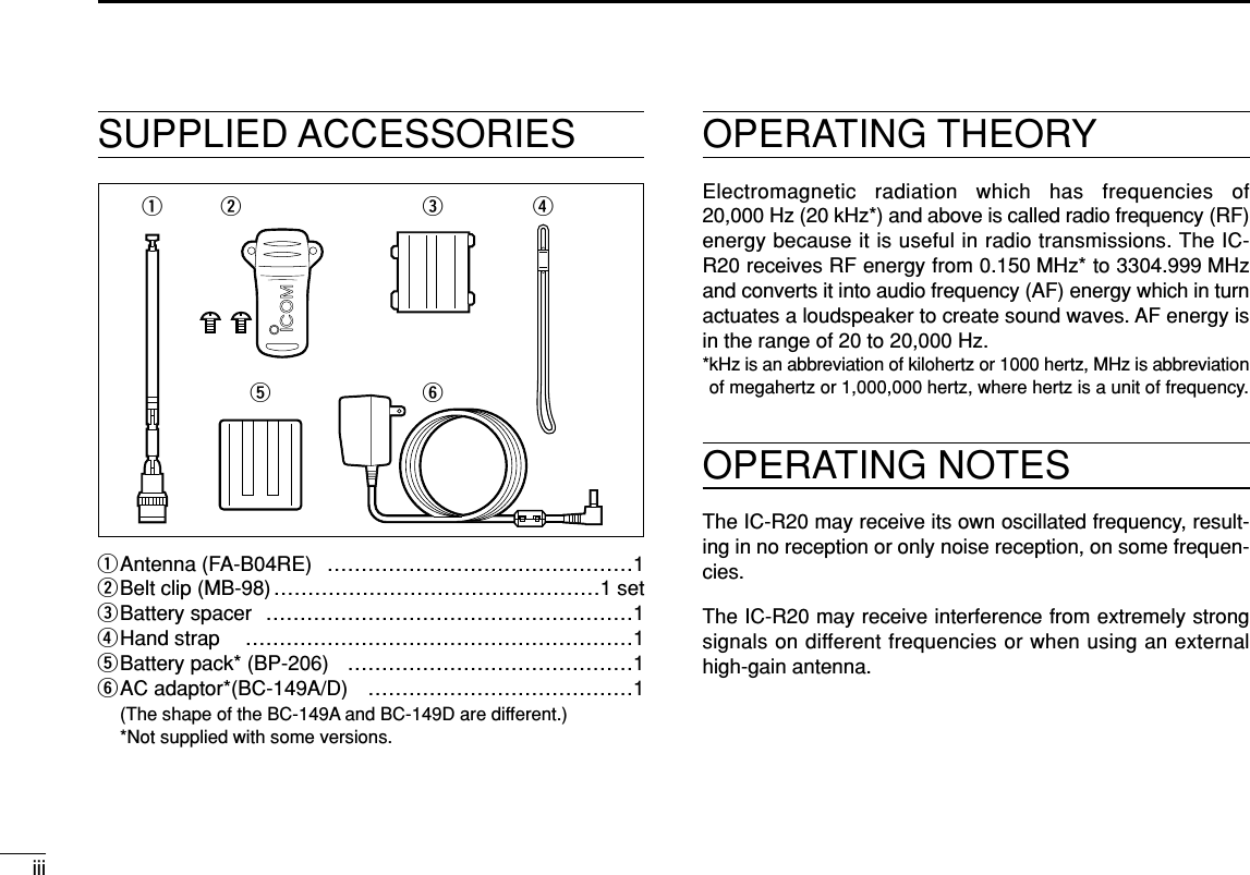
![IIQUICK REFERENCE GUIDEDDAntennaInsert the supplied antenna into theantenna connector and screw downthe antenna as shown at right.NEVER hold the antenna when car-rying the receiver.Keep the jack cover attached whenjack is not in use to protect the con-nectors from dust and moisture.✔For your informationThird-party antennas may in-crease receiver performance.DCharging the batteryqInstall the battery pack (BP-206).wPlug the AC adaptor into an AC outlet.eInsert the adaptor plug into the [DC] jack of the receiver.RRWARNING!:NEVER charge the alkaline batteries. IC-R20to [DC]jackOptional CP-18A/ECigarette lighter cable with DC-DC converterAC adapterBC-149A/Dto cigarette lighter socketto AC outletQuick reference guide](https://usermanual.wiki/ICOM-orporated/269900/User-Guide-409586-Page-7.png)
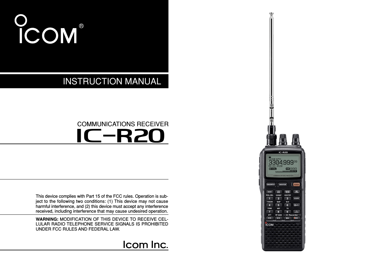
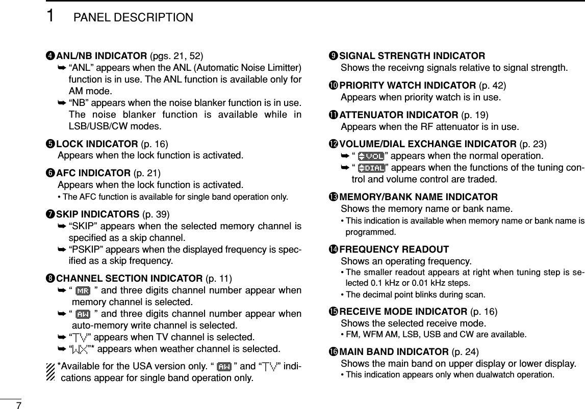
![■Front, top and side panelsqANTENNA CONNECTOR (p. II)Connects the supplied antenna.wSQUELCH KEY [SQL] (p. 18)➥Push and hold to temporarily open the squelch andmonitor the operating frequency.➥While pushing this key, rotate the tuning dial* to adjustthe squelch level.eUP/DOWN KEYS [YY]/[ZZ]Adjust audio volume level.* (p. 17)rUSB JACK [USB]Connect a PC via the optional OPC-1382 CLONINGCABLE for Data/Audio cloning.tEXTERNAL DC-IN CONNECTOR [DC] (p. 9)Connects an AC adaptor or an optional cigarette lightercable for both charging the installed re-chargeable batterypack and operating. yEXTERNAL SPEAKER CONNECTOR [SP/CI-V]➥Connect an optional earphone or headphone.The internal speaker will not function when any exter-nal equipment is connected. (See p. 80 for a list ofavailable options.)➥Connect an optional CT-17 for remote control operation.(p. 68)qwertyuiKEYPAD1PANEL DESCRIPTION1](https://usermanual.wiki/ICOM-orporated/269900/User-Guide-409586-Page-8.png)
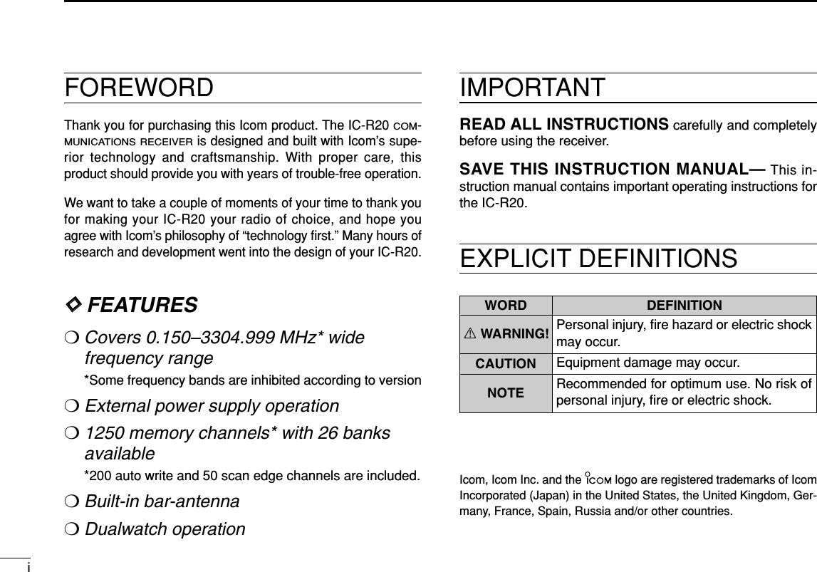
![21PANEL DESCRIPTION1uLEFT DIAL [L-DIAL]➥During single band operation, rotate to adjust audio vol-ume level.* (p. 17)➥During dualwatch operation, activates as the tuning dialfor upper side on the display.*iRIGHT DIAL [R-DIAL]➥Rotate to select the operating frequency.* (p. 12)➥While scanning, changes the scanning direction.*(p. 26)➥While pushing [SQL], sets the squelch level.* (p. 18)➥While pushing [VFO MHz], sets the operating frequencyin 1 MHz or 10 MHz in VFO mode.* (p. 14)➥While pushing [BAND], selects the operating band inVFO mode.* (p. 14)➥While dualwatch operation, activates as the tuning dialfor lower side on the display.* (p. 14)KEYPADqDUALWATCH/CLEAR KEY [DUALWATCH]➥Push for 1 sec. to toggle between single bandand dualwatch operation. (p. 24)➥Clears numeric key input. (p. 15)➥Returns to previous operating condition whilesetting frequency or memory channel, or whilein set mode.➥Cancels the band scope or scan function.(pgs. 22, 35)wMAIN/SUB KEY [MAIN/SUB] (p. 25)➥During dualwatch operation, push to select theMAIN band or SUB band. ➥During dualwatch operation, push for 1 sec. toexchange the upper frequency and lower fre-quency. ePOWER KEY [PWR]Push for 1 sec. to turn the receiver power ONand OFF. rBAND KEY [BAND]➥Push to select the operating frequency band.(p. 14)BANDPOWERMAIN/SUBDUALWATCHDIAL.SEL SWEEP CENTERT-SCAN SKIP M.NTONE SET TSATT RF GAINIC Recorder1234560789BANDDUALWATCHMAIN/SUBPOWERVFOMHz MODESCAN MRS.MWSCOPELOCKRECAFC*The function of tuning control ([DIAL]) and volume control ([Y]/[Z])can be traded. See page 23 for details.](https://usermanual.wiki/ICOM-orporated/269900/User-Guide-409586-Page-9.png)
![31PANEL DESCRIPTIONtVFO/MHz KEY [VFO MHz]➥Push to select VFO mode. (p. 11)➥Push for 1 sec. to toggle between the 1 MHzor 10 MHz tuning steps (p. 14yMODE/SCAN KEY [MODE SCAN]➥Push to select the operating mode (FM, WFM,AM, USB, LSB, CW). (p. 16)➥Push for 1 sec. to start a scan. (p. 35)uMEMORY KEY [MR S.MW] ➥Push to select between memory mode, TVchannel and PreSet channel. (p. 11)➥Push for 1 sec. to enter memory write condi-tion. (p. 26)➥Push for 2 sec. to write the operating fre-quency into the selected memory channel inVFO mode.Push [MR S.MW] for 2 sec. to transfer the dis-played frequency into the VFO in memorymode. (p. 31)iVOLUME/DIAL KEY [1 DIAL SEL]➥Inputs digit ‘1’ for frequency input, memorychannel selection, etc.➥Push for 1 sec. to trade the volume control ([L-DIAL], [Y]/[Z]) and tuning control ([R-DIAL])functions. (p. 23)•√é appears when the [Y]/[Z]keys function asa volume control.oSWEEP KEY [2 SWEEP] (p. 22)➥Inputs digit ‘2’ for frequency input, memorychannel selection, etc.➥Push for 1 sec. to select the tuning step forband scope function. Once a pushing this key,the band scope function sweeps once via thenew tuning step.!0 CENTER KEY [3 CENTER] (p. 22)➥Inputs digit ‘3’ for frequency input, memorychannel selection, etc.➥Push for 1 sec. to return the display frequencyof the band frequency.!1 SCOPE KEY [SCOPE] (p. 22)➥Push to activate the band scope function dur-ing normal operating condition. Or push tostop continuous sweeping.➥Push for 1 sec. to start a continuous sweep-ing.SCOPECENTERSWEEPDIAL SELMRS.MWMODESCANVFOMHz](https://usermanual.wiki/ICOM-orporated/269900/User-Guide-409586-Page-10.png)
![41PANEL DESCRIPTION12345678910111213141516!2 TONE SCAN KEY [4 T-SCAN]➥Inputs digit ‘4’ for frequency input, memorychannel selection, etc.➥Push for 1 sec. to start a tone scan. (p. 48)!3 FREQUENCY SKIP KEY [5 SKIP]➥Inputs digit ‘5’ for frequency input, memorychannel selection, etc.➥Push for 1 sec. to turn the frequency skipfunction ON and OFF in VFO mode. (p. 39)• “PSKIP” appears when the frequency skip functionis in use.➥Push for 1 sec. to set the memory channel asthe following skip channel in memory mode inorder. (p. 39)• Skip channel — “SKIP” appears. • Frequency skip channel — “PSKIP” appears. • Non-skip channel — no skip indicator appears.➥Push for 1 sec. to program a paused fre-quency as a skip frequency while scanning.(p. 39)!4 MEMORY NAME KEY [6 M.N]➥Inputs digit ‘6’ for frequency input, memorychannel selection, etc.➥Push for 1 sec. to turn the memory name indi-cation ON and OFF. (p. 30)!5 AFC KEY [0 AFC]➥Inputs digit ‘0’ for frequency input, memorychannel selection, etc.➥Push for 1 sec. to turn the AFC (AutomaticFrequency Control) function ON and OFF.(p. 21)!6 TONE SQUELCH KEY [7 TONE]➥Inputs digit ‘7’ for frequency input, memorychannel selection, etc.➥Push for 1 sec. to activate the following tonesquelch functions in order.• Tone squelch — “TSQL” appears. (p. 46)• Pocket beep — “TSQLS” appears. (p. 46)• DTCS squelch — “DTCS” appears. (p. 46)• DTCS beep — “DTCSS” appears. (p. 46)• VSC function — “VSC” appears. (p. 46)• No tone operation — no tone indicator appears.!7 SET MODE KEY [8 SET]➥Inputs digit ‘8’ for frequency input, memorychannel selection, etc.➥Push for 1 sec. to enter the set mode. SETTONEAFCM.NSKIPT SCAN](https://usermanual.wiki/ICOM-orporated/269900/User-Guide-409586-Page-11.png)
![51PANEL DESCRIPTION!8 TUNING STEP KEY [9 TS]➥Push for 1 sec. to select the tuning step. (p. 14)➥Inputs digit ‘9’ for frequency input, memorychannel selection, etc.!9 LOCK KEY [• LOCK]➥Inputs MHz digit for frequency input. (p. 15)➥Push for 1 sec. to toggle the lock function ONand OFF. (p. 16)• “ ” appears while the key lock function is in use.@0 REWIND/ATTENUATOR KEY [ΩΩΩΩATT]➥Push to select the track for recorded audio.(p. 64)➥Push and hold to rewind during playing therecorded audio. (p. 64)➥Push for 1 sec. to turn the attenuator functionON and OFF during normal operation. (p. 19)@1 SKIP/RF GAIN KEY [≈≈≈≈RF GAIN]➥Push to select the track for recorded audio.(p. 64)➥Push and hold to skip the recorded audio.(p. 64)➥Push for 1 sec. to enter the RF GAIN setmode. Push to select the item after selectingwith [R-DIAL]. (p. 19)@2 STOP/PLAY [■≈≈]➥Push to start the recorded audio. (p. 64)➥Push to stop the recording or playing audio.(p. 64)➥Push for 1 sec. to enter the play speed setmode. Push to select the item after selectingwith [R-DIAL]. (p. 65)@3 RECORD KEY [ REC]➥Push for 1 sec. to enter the record set mode.Push to select the item after selecting with [R-DIAL]. (p. 65)➥Push to start recording audio. (p. 64)➥Push to pause recording audio. (p. 64)RECRF GAINATTLOCKTS](https://usermanual.wiki/ICOM-orporated/269900/User-Guide-409586-Page-12.png)
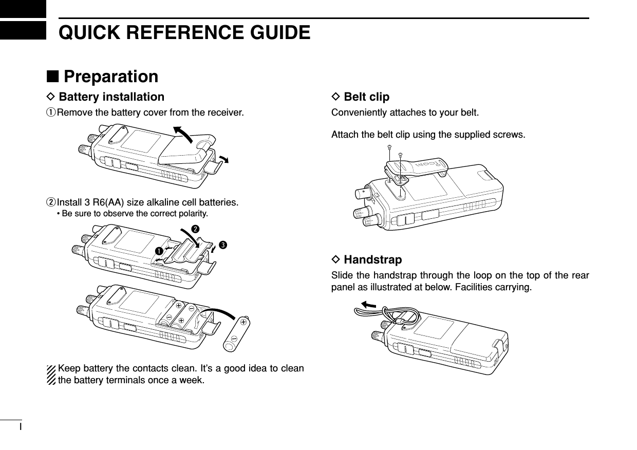
![82BATTERY CHARGING12345678910111213141516■Battery installationBefore installing, or replacing the batteries, push [POWER]for 1 sec. to turn the power OFF.qRemove the battery cover from the receiver.wInstall 3 R6 (AA) size alkaline batteries.• Be sure to observe the correct polarity.Keep the battery contacts clean to avoid rust or poor con-tact. It’s a good idea to clean the battery terminals once aweek.DDBattery pack installationqRemove the battery cover from the receiver.wRemove the supplied battery spacer for R6 (AA) size bat-tery use.eInstall the Li-Ion battery pack (BP-206).• Be sure to observe the correct direction.• Charge Li-Ion battery pack before use.•Battery pack installation•Battery pack removalqwe](https://usermanual.wiki/ICOM-orporated/269900/User-Guide-409586-Page-15.png)
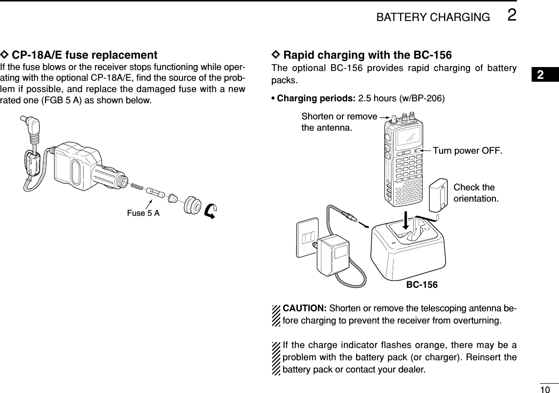
![■CautionDDBattery caution•CAUTION! NEVER short the battery terminals. Also, currentmay flow into nearby metal objects such as a necklace, sobe careful when placing battery pack in handbags, etc.•NEVER incinerate used battery pack or battery cells. Inter-nal battery gas may cause explosion.•NEVER mix old and new batteries.•Make sure all battery cells are the same brand, type andcapacity.Either of the above may cause a fire hazard or damage thereceiver if ignored.DDCharging caution• Recommended temperature for charging:±0˚C to +35˚C (; +32˚F to +95˚F)• Connect the supplied (or optional for some versions) ACadaptor or optional cigarette lighter cable only when charg-ing the battery pack (BP-206). NEVER use other manufac-ture’s chargers.CAUTION: BE SURE to disconnect the CP-18A/E fromthe cigarette lighter socket when charging is finished, be-cause, a slight current still follows in the CP-18A/E and thevehicle’s battery will become exhausted.■Battery chargingDDRegular chargingqAttach the battery pack (BP-206) to the receiver. (Seepage 8)wPlug the AC adaptor (BC-149A/D*) into an AC outlet; or theoptional CP-18A/E into a cigarette lighter socket.* Not supplied with some versions.eInsert the adaptor plug into [DC] of the receiver.•Charging periods: 8 hours (w/BP-206)IC-R20to [DC]jackOptional CP-18A/ECigarette lighter cable with DC-DC converterAC adapterBC-149A/Dto cigarette lighter socketto AC outlet92BATTERY CHARGING](https://usermanual.wiki/ICOM-orporated/269900/User-Guide-409586-Page-16.png)
![11FREQUENCY AND CHANNEL SETTING3■Mode selectionDDVFO modeVFO mode is used for the desired frequency setting within thefrequency coverage.➥Push [VFO MHz] to select VFO mode.What is VFO?VFO is an abbreviation of Variable Frequency Oscillator. Fre-quencies for receiving are generated and controlled by theVFO.DDMemory mode/PreSet*/TV*/Weather†channelsMemory mode is used for operation of memory channelswhich have programmed frequencies. PreSet channels areused for most-often used frequencies for quick recall. *Appears only when PreSet channels/TV channels areprogrammed via the optional CS-R20.†Available for the USA version only.qPush [MR S.MW] to select the memory mode, PreSet, TVor Weather channel in sequence.wRotate [R-DIAL] to select the desired channel.• Only programmed memory channels can be selected.• Entering keypad directly can be selected the desired channel.• See p. 26 for memory programming details.√µMODE ANLAFCTSQLFM146100PSKIP-DUP001DIAL.SEL SWEEP CENTERT-SCAN SKIP M.NTONE SET TSATT RF GAINIC Recorder1234560789BANDDUALWATCHMAIN/SUBPOWERVFOMHz MODESCAN MRS.MWSCOPELOCKRECAFC“µ ” and memory channel number appear.• Memory mode indicationMRS.MWDIAL.SEL SWEEP CENTERT-SCAN SKIP M.NTONE SET TSATT RF GAINIC Recorder1234560789BANDDUALWATCHMAIN/SUBPOWERVFOMHzVFOMHzMODESCAN MRS.MWSCOPELOCKRECAFC √MODE ANLAFCTSQLFM146560PSKIP-DUP• VFO mode indication](https://usermanual.wiki/ICOM-orporated/269900/User-Guide-409586-Page-18.png)
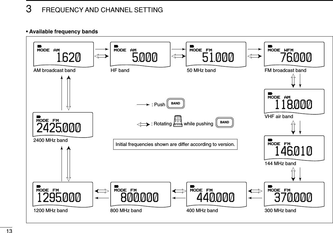
![123FREQUENCY AND CHANNEL SETTING 3■Operating band selectionThe receiver can receive the AM broadcast, HF bands,50 MHz, FM broadcast, VHF air, 144 MHz, 300 MHz,400 MHz, 800 MHz,* 1200 MHz or 2400 MHz.➥Push [BAND] several times to select the desired frequencyband.• When a memory mode is selected, push [VFO MHz] to selectVFO mode first, then push [BAND] to select the desired band.➥While pushing and holding [BAND], rotating [R-DIAL] alsoselects frequency band.Available frequency bands are differ depending on version.See the specification for details.*Some frequency ranges are inhibited for the USA versiondue to local regulation.[R-DIAL]BAND√MODE ANLAFCTSQLWFM76 000PSKIP-DUP√µMODE ANLAFCTSQLFM146100PSKIP-DUP0010√MODE ANLAFCTSQLWFM2chPSKIP-DUPTV√MODE ANLAFCTSQLFM1PSKIP-DUPWX“µ ” and memory channel number appear.• PreSet channel indication• TV channel indication• Weather channel indication (USA version only)• Memory mode indicationPreSet channel number appears.“TV” indication appears.“WX” indication appears.](https://usermanual.wiki/ICOM-orporated/269900/User-Guide-409586-Page-19.png)
![143FREQUENCY AND CHANNEL SETTING 3■Setting a tuning stepThe tuning step can be selected for each frequency band in-dependently , however, the tuning steps, 8.33 kHz and 9 kHz,are appeared when setting the tuning step for the VHF airband and AM broadcast band, respectively. The following tun-ing steps are available for the IC-R20.• 0.01 kHz • 0.1 kHz • 1.0 kHz • 5.0 kHz • 6.25 kHz• 8.33 kHz • 9.0 kHz • 10.0 kHz • 12.5 kHz • 15.0 kHz• 20.0 kHz • 25.0 kHz • 30.0 kHz • 50.0 kHz • 100.0 kHzDDTuning step selectionqPush [VFO MHz] to select VFO mode, if necessary.wPush [BAND] to select the desired frequency band.• Or, while pushing and holding [BAND], rotate the [R-DIAL] to se-lect the desired frequency band.ePush [9 TS] for 1 sec. to enter tuning step selecting condition.rRotate [R-DIAL] to select the desired tuning step.tPush [9 TS] to return to VFO mode.■Setting a frequencyDDUsing the dialqPush [VFO MHz] to select VFO mode, if necessary.wSelect the desired frequency band with [BAND].• Or, while pushing and holding [BAND], rotate the [R-DIAL] to se-lect the desired frequency band.eRotate [R-DIAL] to select the desired frequency.• The frequency changes according to the preset tuning steps.See the left section for setting the tuning step.• Push [VFO MHz] for 1 sec. then rotate [R-DIAL] to change thefrequency in 1 MHz steps, or push for 1 sec. again then rotate[R-DIAL] to change the frequency in 10 MHz steps. (Each pushfor 1 sec. toggles 1 MHz or 10 MHz tuning steps.)FMMODE14601000FMMODE14601000[R-DIAL] changes the frequen-cy according to the selected tuning step.While pushing [VFO MHz], [R-DIAL] changes the frequency in 1 MHz steps (default).[R-DIAL]BANDVFOMHzSET TS:5.0kHz√MODE ANLAFCTSQLFM146010PSKIP-DUP5 kHz tuning step[R-DIAL]TS9BANDVFOMHz](https://usermanual.wiki/ICOM-orporated/269900/User-Guide-409586-Page-21.png)
![153FREQUENCY AND CHANNEL SETTING DDUsing the keypadThe frequency can be directly set via numeralkeys.• When editting a frequency outside of the fre-quency range, the previously displayed frequencyis automatically recalled after editting last digit.qPush [VFO MHz] to select VFO mode, ifnecessary.wEnter the desired frequency via the keypad.• Direct input can be set until 1 kHz digit, rotate[R-DIAL] to set below 1 kHz frequency afterset tuning steps, if necessary. (See the previ-ous page for setting the tuning step.)1234560789LOCKAFCDUALWATCHVFOMHzPushing [VFO MHz] omits the entry of 100 kHz and below, when you want toedit to these digits “0.” Push [DUALWATCH] to cancel the entry.AMMODE000010AMMODE000010AMMODE000 684AMMODE000684AMMODE000684FMMODE1000FMMODE12 000FMMODE126000FMMODE1260000FMMODE1260000FMMODE1260240FMMODE1260 240FMMODE1260240FMMODE126024012244668VFOMHz0AFC0AFC0AFCLOCK LOCK• Editting to 0.684 MHz • Editting to 1260 MHz • Changing 100 kHz and below.Editting 1260.000 MHz to 1260.240 MHz](https://usermanual.wiki/ICOM-orporated/269900/User-Guide-409586-Page-22.png)
![163FREQUENCY AND CHANNEL SETTING 12345678910111213141516■Receive mode selectionReceive modes are determined by the physical properties ofthe radio signals. The receiver has 6 receive modes: FM,WFM, AM, LSB, USB and CW modes. The mode selection isstored independently in each band and memory channels.Typically, AM mode is used for the AM broadcast stations(0.495–1.620 MHz) and VHF air band (118–135.995 MHz),and WFM is used for FM broadcast stations (76–107.9 MHz).➥Push [MODE SCAN] several times to select the desiredreceive mode.■Lock functionTo prevent accidental frequency changes and unnecessaryfunction access, use the lock function. ➥Push [• LOCK] for 1 sec. to turn the lock function ON andOFF.• “ ” appears while the lock function is activated.•[SQL] and [YY]/[ZZ]can be used while the lock function is in usewith default setting. Either or both [SQL] and [YY]/[ZZ]keys arealso be locked in set mode. (p. 49)√MODE ANLAFCTSQLFM146010PSKIP-DUPDIAL.SEL SWEEP CENTERT-SCAN SKIP M.NTONE SET TSATT RF GAINIC Recorder1234560789BANDDUALWATCHMAIN/SUBPOWERVFOMHz MODESCAN MRS.MWSCOPELOCKRECAFC“ ” appears while the lock function is in use.LOCKDIAL.SEL SWEEP CENTERT-SCAN SKIP M.NTONE SET TSATT RF GAINIC Recorder1234560789BANDDUALWATCHMAIN/SUBPOWERVFOMHz MODESCAN MRS.MWSCOPELOCKRECAFCMODESCANWFMMODEAMMODEFMMODE76 000118000146010PSKIPPSKIPPSKIPFM modeAM modeWFM mode](https://usermanual.wiki/ICOM-orporated/269900/User-Guide-409586-Page-23.png)
![17BASIC OPERATION4■ReceivingMake sure charged battery pack (BP-206) or brand new al-kaline batteries are installed (p. 8).qPush [POWER] for 1 sec. to turn power ON.wRotate [L-DIAL] (or push [YY]or [ZZ]) to set the desiredaudio level. • The frequency display shows the volume level while setting. Seethe section at right for details.eSet the receiving frequency. (p. 14)rSet the squelch level. (p. 18)• While pushing [SQL], rotate [R-DIAL].• The first click of [R-DIAL] indicates the current squelch level.• “LEVEL 1” is loose squelch and “LEVEL 9” is tight squelch.• “AUTO” indicates automatic level adjustment with a noise pulsecount system.• Push and hold [SQL] to open the squelch manually.tWhen a signal is received:• Squelch opens and audio is emitted.• The S-meter shows the relative signal strength level.■Setting audio volumeThe audio level can be adjusted through 39 levels.➥Push and hold [SQL], rotate [L-DIAL] or push [YY]or [ZZ]toadjust the audio level. • While using [YY]/[ZZ], pushing and holding either key change theaudio level continuously.• The display shows the volume level while setting.√MODE ANLAFCTSQLFMVOL146010PSKIP-DUP√VOL√VOL[L-DIAL]Minimum setting(no audio)Maximum settingSQL√MODE ANLAFCTSQLFM146010P S KIP-DUPATTq [POWER]e Set frequencyr Set squelch levelw Set audio levele Select bandr Push for setting the squelch (Push to monitor)](https://usermanual.wiki/ICOM-orporated/269900/User-Guide-409586-Page-24.png)
![184BASIC OPERATION4■Squelch level settingThe squelch circuit mutes the received audio signal depend-ing on the signal strength. The receiver has 9 squelch levels,a continuously open setting and an automatic squelch setting.➥While pushing and holding [SQL], rotate [R-DIAL] to se-lect the squelch level.• “LEVEL 1” is loose squelch and “LEVEL 9” is tight squelch.• “AUTO” indicates automatic level adjustment with a noise pulsecount system.• “OPEN” indicates continuously open setting.■Monitor functionThis function is used to listen to weak signals without disturb-ing the squelch setting or to open the squelch manually evenwhen mute functions such as the tone squelch are in use.➥Push and hold [SQL] to monitor the operating frequency.• The 1st segment of the S-meter blinks.The [SQL] key can be set to ‘sticky’ operation in expandedset mode. See page 54 for details.√MODE ANLAFCTSQLFM146010PSKIP-DUPThe 1st segment blinksSQLSQUELCH:AUTO√MODE ANLAFCTSQLFM146010PSKIP-DUPSQUELCH:LEVEL9√MODE ANLAFCTSQLFM146010PSKIP-DUPAutomatic squelchMaximum level[R-DIAL]SQL](https://usermanual.wiki/ICOM-orporated/269900/User-Guide-409586-Page-25.png)
![■Attenuator functionThe attenuator prevents a desired signal from distorting whenvery strong signals are near the desired frequency or whenvery strong electric fields, such as from a broadcasting sta-tion, are near your location.➥Push [ΩΩΩΩATT]for 1 sec. to toggle the attenuator functionON and OFF.• “ATT” appears when the attenuator function is in use.■RF gainThe receiver gain can be reduced with the RF gain setting.This may help to remove undesired weak signals while mon-itoring strong signals. The RF gain may be useful for setting aminimum level at which to hear signals for SSB/CW modes .➥Push [≈≈≈≈RF GAIN]for 1 sec. to enter the RF gain set-ting condition, then rotate [R-DIAL] to select the desiredRF gain level.• Normally this setting is used maximum level.• Push [DUALWATCH] to exit the RF gain setting condition.SET-RF-GAIN:MAX√MODE ANLAFCTSQLUSB14 120PSKIP-DUPSET-RF-GAIN:5√MODE ANLAFCTSQLUSB14 120PSKIP-DUPMaximum levelSetting level5[R-DIAL]RF GAINATT√MODE ANLAFCTSQLFM146010PSKIP-DUPATTDIAL.SEL SWEEP CENTERT-SCAN SKIP M.NTONE SET TSATT RF GAINIC Recorder1234560789BANDDUALWATCHMAIN/SUBPOWERVFOMHz MODESCAN MRS.MWSCOPELOCKRECAFC“AT T ” appears while the attenuator functions is in use.194BASIC OPERATION](https://usermanual.wiki/ICOM-orporated/269900/User-Guide-409586-Page-26.png)
![204BASIC OPERATION4Duplex communication uses 2 different frequencies for trans-mitting and receiving. Generally, duplex is used in communi-cation through a repeater, some utility communications, etc.During duplex operation, the transmit station frequency isshifted from the receive station frequency by the offset fre-quency. Repeater information (offset frequency and shift di-rection) can be programmed into memory channels. (p. 26)DDSettingqSet the receive station frequency (repeater output frequency).wPush [8 SET] for 1 sec. to enter set mode.eRotate [R-DIAL] to select “SET EXPAND” item, then push[8 SET].rRotate [R-DIAL] to select “ON.”tRotate [R-DIAL] to select “OFFSET FREQ,” then push[8 SET].yRotate [R-DIAL] to set the desired offset frequency within0.00000–159.99999 MHz range, then push [8 SET].• The tuning step, selected in VFO mode, is used for setting.• Push [VFO MHz] for 1 sec. then rotate [R-DIAL] to change thefrequency in 1 MHz steps, or push for 1 sec. again then rotate[R-DIAL] to change the frequency in 10 MHz steps. (Each pushfor 1 sec. toggles 1 MHz or 10 MHz tuning steps.)uRotate [R-DIAL] to select “DUPLEX.”iRotate [R-DIAL] to select “–DUP” or “+DUP.”oPush [DUALWATCH] to exit set mode.!0Push and hold [SQL] to monitor the transmit station fre-quency (repeater input frequency) directly.DUPLEX--DUP>OFF-+DUP----------------OFFSET-FREQ----0.000.00----------------[R-DIAL]DUALWATCHSET8SET TS:5.0kHz√MODE ANLAFCTSQLFM146010P S KIP-DUP***-SET-MODE-***>SET-EXPAND-FM-ANTENNA-AM-ANTENNA-AF-FILTER-ANL-NOISE-BLANKER----------------■Duplex operationUSINGEXPANDED SET MODE](https://usermanual.wiki/ICOM-orporated/269900/User-Guide-409586-Page-27.png)
![214BASIC OPERATION■AFC functionThe AFC (Automatic Frequency Control) function tunes thedisplayed frequency automatically when an off-center fre-quency is received. It activated in FM/WFM modes only withsingle band operation.➥Push [0 AFC]to toggle the AFC function ON and OFF.• “AFC” appears when the AFC function is in use.NOTE: The AFC function is not available during duwal-watch operation.■NB/ANL functionThe NB (noise blanker) function removes pulse-type noisewhen USB, LSB or CW mode is selected. The ANL (Auto-matic Noise Limitter) function reduces noise componentswhen AM mode is selected.See page 22 for setting detailsNOTE: No display indication appears during dualwatchfunction, but both functions are activate while in specificmodes.ATT√MODE ANLAFCTSQLFM1260000P S KIP-DUPATT√MODE ANLAFCTSQLFM1260000PSKIP-DUPDIAL.SEL SWEEP CENTERT-SCAN SKIP M.NTONE SET TSATT RF GAINIC Recorder1234560789BANDDUALWATCHMAIN/SUBPOWERVFOMHz MODESCAN MRS.MWSCOPELOCKRECAFC“AFC” appears while the AFC function is in use.0AFC“ ” “ ” oran off-frequency is received.appears when](https://usermanual.wiki/ICOM-orporated/269900/User-Guide-409586-Page-28.png)
![224BASIC OPERATION12345678910111213141516■Band scopeThe band scope function allows you to visually check a spec-ified frequency range. Sweep range can be selected from ±14kHz through ±1400 kHz.qSet the desired frequency as band scope center frequency.wWhile pushing and holding [2 SWEEP], rotate [R-DIAL] toselect the sweep steps, if desired.• Available steps are 1, 5, 6.25, 8.33, 9, 10, 12.5, 15, 20, 25, 30,50 and 100 kHz.• Each pushing [SWEEP] changes the sweep step and starts sin-gle sweeping at each times.ePush [SCOPE] momentarily to start single sweeping orpush for 1 sec. to start continuous sweeping. • Signal conditions (strengths) appear starting from the center ofthe range.rRotate [R-DIAL] to set the highlighted cursor to the de-sired waveform and set the frequency of the signal.• Push [3 CENTER] for 1 sec. to return to original sweep centerfrequency.tPush [DUALWATCH] to cancel sweeping and returns tonormal condition. ✔CONVENIENT!The scope function can also be started with the following op-eration for easy setting.qSet the desired frequency as band scope center frequency.wPush [SWEEP] for 1 sec. to start single sweeping.• Each pushing [SWEEP] changes the sweep step and starts sin-gle sweeping at each times.√MODEANLAFCTSQLFM145780PSKIPSWEEP10k-DUP[R-DIAL]SWEEP2](https://usermanual.wiki/ICOM-orporated/269900/User-Guide-409586-Page-29.png)
![234BASIC OPERATION■[DIAL] function assignmentThe frequency control dial can be traded with an audio volumecontrol dial or [YY]/[ZZ]keys to suit your preference. ➥Push [1 DIAL] for 1 sec. to toggle the dial function from tun-ing dial and audio volume.•“∂” appears when [YY]/[ZZ]function as an tuning dial.•Single band operation•Dualwatch operation√MODE ANLAFCTSQLFM146560PSKIP-DUP∂145250438000AFC -DUP-DUPFMTSQLTSQLPSPSPRIOPRIOFM0000000000FM[R-DIAL][L-DIAL]DIAL.SEL1“ √” indication “ ∂” indicationFrequency, Memory channel,Audio volume [R-DIAL] Squelch level, Scanningdirection, Set mode item and condition setAudio volume setFrequency, Memory channel,[L-DIAL] Squelch level, Scanning [Y]/[Z] direction, Set mode itemand condition set“ ” indication “ ” indicationFrequency, Memory channel,Audio volume [R-DIAL] Squelch level, Scanning[L-DIAL] direction, Set mode item and condition setAudio volume setFrequency, Memory channel,[Y]/[Z]Squelch level, Scanning direction, Set mode itemand condition set](https://usermanual.wiki/ICOM-orporated/269900/User-Guide-409586-Page-30.png)
![245DUALWATCH OPERATION12345678910111213141516■Setting audio volumeqPush [DUALWATCH] for 1 sec. to enter the dualwatch op-eration, if necessarywPush and hold [SQL], push [YY]or [ZZ]to adjust the audiolevel for the main band. • Pushing and holding either key change the audio level continu-ously.• The display shows the volume level while setting.While pushing either [YY]or [ZZ], rotate [L-DIAL] for upperband’s volume adjustment, or [R-DIAL] for lower band’svolume adjustment.■Squelch level settingqPush [DUALWATCH] for 1 sec. to enter the dualwatch op-eration, if necessarywWhile pushing and holding [SQL], rotate [L-DIAL] forupper band’ squelch adjustment, or rotate [R-DIAL] forlower band’s squelch adjustment.• “LEVEL 1” is loose squelch and “LEVEL 9” is tight squelch.• “AUTO” indicates automatic level adjustment with a noise pulsecount system.• “OPEN” indicates continuously open setting.145 000433 000AFC -DUP-DUPFMTSQLTSQLPSPSP RIOP RIOLSB0000000000145250438000AFC -DUP-DUPFMTSQLTSQLPSPSPRIOPRIOFM0000000000PSPSPSSQUELCH:LEVEL9438.000SQUELCH:AUTOPS145.250[R-DIAL][L-DIAL]SQLUpper band settingLower band setting145250438000AFC -DUP-DUPFMVOLVOLTSQLTSQLPSPSPRIOPRIOFM0000000000145250438000PSPS000000Upper band settingLower band settingSQL](https://usermanual.wiki/ICOM-orporated/269900/User-Guide-409586-Page-31.png)
![255DUALWATCH OPERATION■Main band selection➥Push [MAIN/SUB] momentarily to select the upper bandor lower band as main band (operating band) alternately.■Band exchange➥Push [MAIN/SUB] for 1 sec to exchange the upper band’sfrequency and lower band’s frequency.145 000433 000AFC -DUP-DUPFMTSQLTSQLPSPSP RIOP RIOLSB0000000000145250438000AFC -DUP-DUPFMTSQLTSQLPSPSPRIOPRIOFM0000000000438000145250-DUP-DUPFMTSQLTSQLPSPSPRIOPRIOFM0000000000PSPSMAIN/SUB145 000433 000AFC -DUP-DUPFMTSQLTSQLPSPSP RIOP RIOLSB0000000000145250438000AFC -DUP-DUPFMTSQLTSQLPSPSPRIOPRIOFM0000000000438000145250-DUP-DUPFMTSQLTSQLPSPSPRIOPRIOFM0000000000PSPSMAIN/SUB](https://usermanual.wiki/ICOM-orporated/269900/User-Guide-409586-Page-32.png)
![266MEMORY CHANNELS■General descriptionThe receiver has 1050 memory channels including 50 scanedge memory channels (25 pairs) for storage of often-usedfrequencies. And a total of 26 memory banks, A to Z are avail-able for usage by group, etc. Up to 100 channels can be as-signed into a bank.DDMemory channel contentsThe following information can be programmed into memorychannels:• Operating frequency (p. 14)• Receive mode (p. 16)• Duplex direction (+DUP or –DUP) with an offset fre-quency (p. 20)• Tone squelch or DTCS squelch ON/OFF (p. 45)• Tone squelch frequency or DTCS code with polarity(p. 46)• Scan skip information* (p. 39). ■Memory channel programmingqPush [VFO MHz] to select VFO mode.wSet the desired frequency:➥Select the desired band with [BAND].➥Set the desired frequency with [R-DIAL].➥Or set the desired frequency with [KEYPAD].➥Set other data (e.g. offset frequency, duplex direction, tonesquelch, etc.), if desired.ePush [MR S.MW] for 1 sec. to select the select memorywrite condition.• 1 short and 1 long beep sound.•“µ” indicator blinks.rRotate [R-DIAL] to select the desired channel.• Scan edge channel, 00A/B to 24A/B can also be selected.tPush [MR S.MW] for 1 sec.• 3 beeps sound• Memory channel number automatically increases when contin-uing to push [MR S.MW] after programming.[EXAMPLE]: Programming 145.870 MHz into memory channel 20 (blank channel).√µMODEANLAFCTSQLTSQLFMFM145870PSKIP-DUP-DUP001√µMODEANLAFCTSQLTSQLFM145870PSKIP-DUP-DUP020√µMODEANLAFCTSQLTSQLFM145870PSKIP-DUP-DUP020>CLEARCLEAR-SKIPSKIP-:OFF:OFF-MNAME:MNAME:-BNAME:-BNAME:-BANKBANK-:----:----001001µ.146.010FM>CLEARCLEAR-SKIPSKIP-:OFF:OFF-MNAME:MNAME:-BNAME:-BNAME:-BANKBANK-:----:----020020µ.--------------------------------Push for 1 sec. RotateMRS.MWPush for 1 sec.MRS.MW12345678910111213141516](https://usermanual.wiki/ICOM-orporated/269900/User-Guide-409586-Page-33.png)
![276MEMORY CHANNELS■Memory bank settingThe IC-R20 has a total of 26 banks (A to Z). Regular memorychannels, 000 to 999, are assigned into the desired bank foreasy memory management.qPush [MR S.MW] for 1 sec. to select the select memorywrite condition.• 1 short and 1 long beep sound.•“µ” indicator blinks.wRotate [R-DIAL] to select the desired memory channel.eWhile pushing [8 SET], rotate [R-DIAL] to select “BANK”item.• “BANK” item can also be selected by pushing [8 SET] severaltimes.• Bank group and channel number is displayed if the selectedmemory channel has already been assigned into a bank, theprevious.rWhile pushing [BAND], rotate [R-DIAL] to select the de-sired bank group from “A” to “Z.”• The bank group can also be selected by pushing [BAND] sev-eral times.tAfter releasing [BAND], rotate [R-DIAL] to select the bankchannel number from “00” to “99.”• Vacant bank channel numbers are only be displayed.yPush [MR S.MW] for 1 sec. to set the channel into thebank.• Return to the previous indication.-BNAME:FM>BANK-:A-00012µ.146.010Bank channel is selected with [R-DIAL]-BNAME:FM>BANK-:A-00012µ.146.010Bank group is selected with BANDFM>CLEAR-SKIP-:OFF-MNAME:-BNAME:-BANK-:----012µ.146.010FM>BANK-:----012µ.146.010is pushedAfter[R-DIAL]SET8SET8MRS.MWBANDSET TS:5.0kHz√MODE ANLAFCTSQLFM146010P S KIP-DUP](https://usermanual.wiki/ICOM-orporated/269900/User-Guide-409586-Page-34.png)
![286MEMORY CHANNELS■Memory bank selectionqPush [MR S.MW] to select memory mode.wWhile pushing [BAND], rotate [R-DIAL] to select the de-sired bank (A to Z).• The bank can also be selected by pushing [BAND] severaltimes.• The only programmed banks are displayed.eRotate [R-DIAL] to select the bank channel.• The only programmed channels are displayed.rTo return to regular memory condition, rotate [R-DIAL] whilepushing [BAND], or push [BAND] several times.ATT√µMODE ANLAFCTSQLFM145870PSKIP-DUPA99Bank initialBank chanel numberATT√µMODE ANLAFCTSQLFM145870PSKIP-DUP001√µMODE ANLAFCTSQLAM118000P S KIP-DUPA12√µMODE ANLAFCTSQLFM438720P S KIP-DUPY01Rotate [R-DIAL] while pushing [BAND]Appears only the programmed bank. [R-DIAL]MRS.MWBANDSET TS:5.0kHz√MODE ANLAFCTSQLFM146010P S KIP-DUP12345678910111213141516](https://usermanual.wiki/ICOM-orporated/269900/User-Guide-409586-Page-35.png)
![296MEMORY CHANNELS■Programming memory/bank name Each memory channel can be programmed with an alphanu-meric channel name for easy recognition and can be indicatedindependently by channel. Names can be a maximum of 8characters.qPush [MR S.MW] to select memory mode.wRotate [R-DIAL] to select the desired memory channel.ePush [MR S.MW] for 1 sec. to select the select memorywrite condition.• 1 short and 1 long beep sound.•“µ” indicator blinks.rWhile pushing [8 SET], rotate [R-DIAL] to select “BNAME”or “MNAME” when programming the memory name or thebank name, respectively.• The item can also be selected by pushing [8 SET] several times.• After selecting the memory or bank name programming condi-tion, an under bar blinks for the first digit.tRotate [R-DIAL] to select the desired character.• The selected character blinks.• While pushing [6 M.N], rotate [R-DIAL] to select the charactergroup.yWhile pushing [BAND], rotate [R-DIAL] to move the cur-sor to left or right.• Push [BAND] to move the cursor to right.uRepeat steps tand yuntil the desired 8-character chan-nel names are displayed.iPush [MR S.MW] for 1 sec. to program the name and exitthe channel name programming condition.• 3 beeps sound.•Available charactersA to Z, 0 to 9, (, ), ✱, +, –, ,, /, |, = and space.NOTE: One bank name can only be programmed intoeach bank. Therefore, the previously programmed bankname will be displayed when bank name indication is se-lected. And also, the programmed bank name is assignedfor the other bank channels automatically.FM-MNAME:-BANK-:C-11012µ.145.700FM>MNAME:Ric>BNAME:>BNAME:GRO-BANK-:C-11012µ.145.700Bank name Memory nameFM-MNAME:>BNAME:-BANK-:C-11012µ.145.700FM>MNAME:>BNAME:-BANK-:C-11012µ.145.700Memory name selectionBank name selectionFM>BANK-:C-11012µ.145.700](https://usermanual.wiki/ICOM-orporated/269900/User-Guide-409586-Page-36.png)
![306MEMORY CHANNELSDDAvailable characters ■Selecting memory/bank nameindicationDuring memory mode operation, one of the programmedmemory name or bank name can be displayed below the fre-quency indication.qPush [MR S.MW] to select memory mode.• Push [BAND] several times to select the desired bank group.wWhile pushing [6 M.N], rotate [R-DIAL] to select display in-dication type from bank name or memory name.ATTB:GROUP1√µMODE ANLAFCTSQLFM145700PSKIP-DUP012M:Ricky√µMODE ANLAFCTSQLFM145700PSKIP-DUP012B:GROUP1√µMODE ANLAFCTSQLFM145700PSKIP-DUP012When no memory or bank name is programmed with the selected memory chan-nel, no indication is dis-played.M.N6[R-DIAL]12345678910111213141516A B C D E F G H I J K L M N O P Q R S T U V W X Y Za b c d e f g h i j k l m n o p q r s t u v w x y z0 1 2 3 4 5 6 7 8 9‰ Ò ¨ Î ! " # $ % & ' ( ) * + , - . / : ; < = > ? @ [ \ ] ^ _ { | } ~0 1 2 4 3(space)](https://usermanual.wiki/ICOM-orporated/269900/User-Guide-409586-Page-37.png)
![316MEMORY CHANNELS■Copying memory contentsThis function transfers a memory channel’s contents to VFO(or another memory channel). This is useful when searchingfor signals around a memory channel frequency and for re-calling the offset frequency, subaudible tone frequency etc.DMemory➪VFOqSelect the memory channel to be copied.➥Push [MR S.MW] to select memory mode, then rotate[R-DIAL] to select the desired memory channel.• Select the bank channel with [BAND] and [R-DIAL], if desired.wPush [MR S.MW] for 1 sec. to select the select memorywrite condition.• 1 short and 1 long beep sound.•“µ” indicator blinks.ePush [VFO MHz] to select “VFO.” • Rotate [R-DIAL] can also select “VFO.”rPush [MR S.MW] for 1 sec. to write the selected channelcontents to VFO mode.• Returns to VFO mode automatically.Pushing [MR S.MW] for 2 sec. at the step w, can also becopied the memory contents to VFO. In this case, thesteps eand rare not necessary.DMemory➪memoryqSelect the memory channel to be copied.➥Push [MR S.MW]to select memory mode, then rotate [R-DIAL] to select the desired memory channel.wPush [MR S.MW] for 1 sec. to select the select memorywrite condition.• 1 short and 1 long beep sound.•“µ” indicator blinks.• Do not hold [MR S.MW] for more than 1 sec. otherwise thememory contents will be copied to VFO.eRotate [R-DIAL] to select the target memory channel.rPush [MR S.MW] for 1 sec. again to copy.[EXAMPLE]: Copying channel 20 to 51.√µMODEANLAFCTSQLTSQLFMFMFM145870P S KIP-DUP-DUP TSQLTSQL-DUP-DUP020√µMODEANLAFCTSQLTSQLFM145870PSKIP-DUP-DUP051>CLEARCLEAR-SKIPSKIP-:OFF:OFF-MNAME:MNAME:-BNAME:-BNAME:-BANKBANK-:----:----020020µ.145.870FM>CLEARCLEAR-SKIPSKIP-:OFF:OFF-MNAME:MNAME:-BNAME:-BNAME:-BANKBANK-:----:----051051µ.--------------------------------Select memory channel Push for 1 sec. RotateMRS.MWMRS.MWPush for 1 sec.MRS.MW](https://usermanual.wiki/ICOM-orporated/269900/User-Guide-409586-Page-38.png)
![326MEMORY CHANNELS■Memory clearingContents of programmed memories can be cleared (blanked),if desired.qPush [MR S.MW] for 1 sec. to select the select memorywrite condition.• 1 short and 1 long beeps sound.•“µ” indicator blinks.• Do not hold [MR S.MW] for more than 2 sec. otherwise thememory contents will be copied to VFO.wRotate [R-DIAL] to select the desired memory channel tobe cleared.eWhile pushing [8 SET], rotate [R-DIAL] to select “CLEAR.”• “CLEAR” item can also be selected by pushing [8 SET] severaltimes.rPush [MR S.MW] for 1 sec. to clear the contents.• 3 beeps sound.• The cleared channel changes to blank channel• Return to the select memory write condition.— “µ” indicatorblinks. Push [DUALWATCH] to exit the select memory write con-dition, then push [VFO MHz] to return to VFO mode.☞NOTE: Be careful!— the contents of cleared memoriesCANNOT be recalled even in bank channel opera-tion.FM>CLEAR-SKIP-:OFF-MNAME:-BNAME:-BANK-:----028µ.144.010FM>CLEAR-SKIP-:OFF-MNAME:-BNAME:-BANK-:----028µ.144.010Push for 1 sec.MRS.MWFM>CLEAR-SKIP-:OFF-MNAME:-BNAME:-BANK-:----028µ.144.010>CLEAR-SKIP-:OFF-MNAME:-BNAME:-BANK-:----FM>BANK-:----028µ.144.010is pushedseveral times.After[R-DIAL]SET8SET8MRS.MWSET TS:5.0kHz√MODE ANLAFCTSQLFM146010P S KIP-DUP12345678910111213141516](https://usermanual.wiki/ICOM-orporated/269900/User-Guide-409586-Page-39.png)
![336MEMORY CHANNELS■Erasing/transferring bank contentsThe bank contents of programmed memory channels can becleared or reassigned to another memory bank.INFORMATION: Even if the memory bank contents arecleared, the memory channel contents still remain pro-grammed.qSelect the desired bank contents to be transferred orerased from the bank.➥Push [MR S.MW] to select memory mode.➥While pushing [BAND], rotate [R-DIAL] to select thedesired memory bank group.➥Rotate [R-DIAL] to select the bank channel.wPush [MR S.MW] for 1 sec. to enter the select memorywrite condition.• 1 short and 1 long beeps sound.• Displays the original memory channel number automatically and“µ” indicator blinks.• Do not hold [MR S.MW] for more than 2 sec., otherwise thememory contents will be copied to VFO.ePush [8 SET] once to select “BANK” item.• While pushing [8 SET] then rotate [R-DIAL] also selectable“BANK” item.rWhile pushing [BAND], rotate [R-DIAL] to select the de-sired bank group to be transfer.• Select “– – – –” indication when erasing the contents from thebank.tRotate [R-DIAL] to select the desired bank channel.yPush [MR S.MW] for 1 sec.FM>CLEAR-SKIP-:OFF-MNAME:-BNAME:>BANK-:----028µ.145.700FM>CLEAR-SKIP-:OFF-MNAME:-BNAME:>BANK-:R-00028µ.145.700When transferring When erasing ATTB:GROUP1√µMODE ANLAFCTSQLFM145700PSKIP-DUPA93FM>CLEAR-SKIP-:OFF-MNAME:-BNAME:OSAKA-BANK-:A-93642µ.145.700Push for 1 sec.MRS.MW](https://usermanual.wiki/ICOM-orporated/269900/User-Guide-409586-Page-40.png)
![347SCAN OPERATION12345678910111213141516■Scan typesScanning searches for signals automatically and makes iteasier to locate new stations for contact or listening purposes.There are 7 scan types and 4 resume conditions to suit youroperating needs.FULL SCAN (p. 35) Repeatedly scans all frequen-cies over the entire band. Some frequency ranges arenot scanned according to thefrequency coverage of the re-ceiver’s version.150kHz3304.980MHzScanJumpSELECTED BAND SCAN(p. 35)Repeatedly scans all frequen-cies over the entire selectedband. BandedgeBandedgeScanJumpALL/SELECTED BANKSCAN (p. 37)Repeatedly scans all bankchannels or selected bankchannels. The skip scan isalso available.SKIPSKIPA99 A03A00 A01 A02A04A98A05FREQUENCY/MEMORYSKIP FUNCTION (p. 39)Skips unwanted frequenciesor channels that inconve-niently stop scanning. Thisfunction can be turned ONand OFF by pushing andholding [5 SKIP] in eitherVFO or memory mode.BandedgeBandedgeScanSKIP SKIPJumpPROGRAMMED SCAN(p. 37)Repeatedly scans betweentwo user-programmed fre-quencies. Used for checkingfor frequencies within a speci-fied range such as repeateroutput frequencies, etc.Bandedge xxA xxBBandedgeScan edgesScanJumpMEMORY (SKIP) SCAN(p. 37)Repeatedly scans memorychannels except those set asskip channel. Skip channelscan be turned ON and OFFby pushing and holding [5SKIP] in memory mode.SKIPSKIPM 0 M 4M 1 M 2 M 3M 5M 199M 6](https://usermanual.wiki/ICOM-orporated/269900/User-Guide-409586-Page-41.png)
![357SCAN OPERATION■Full/band/programmed scan qSelect VFO mode with [VFO MHz].• Select the desired frequency band with [BAND], if desired.wSet the squelch level.eWhile pushing and holding [MODE SCAN], rotate [R-DIAL]to select the desired scanning type.• “ALL” for full scan; “BAND” for band scan, “PROG-xx” for pro-grammed scan (xx= 0 to 24; programmed scan edges numbersonly displayed)rTo start the scan, release [MODE SCAN].• Scan pauses when a signal is received.• Rotate [R-DIAL] to change the scanning direction, or resumesmanually.• Push [DUALWATCH] again to stop the scan.About the scanning steps: The selected tuning step ineach frequency band (in VFO mode) is used during scan.√MODE ANLAFCTSQLFM148800PSKIP-DUP√MODE ANLAFCTSQLFM148800PSKIP-DUPP01• During full/band scan • During programmed scanSCAN:ALL√MODE ANLAFCTSQLFM146010PSKIP-DUPSCAN:BAND√PSKIPSCAN:PROG-01√PSKIP• Full scan selection• Band scan selection• Programmed scan selectionSelectable between “ 00” to “24” if programmed[R-DIAL]VFOMHzMODESCAN](https://usermanual.wiki/ICOM-orporated/269900/User-Guide-409586-Page-42.png)
![367SCAN OPERATION■Scan edges programmingScan edges can be programmed in the same manner asmemory channels. Scan edges are programmed into scanedges, 00A/00B to 24A/24B, in memory channels.qPush [VFO MHz] to select VFO mode.wSet the desired frequency:➥Select the desired band with [BAND].➥Set the desired frequency with [R-DIAL].➥Set other data (e.g. offset frequency, duplex direction, tonesquelch, etc.), if desired.ePush [MR S.MW] for 1 sec. to select select memory writecondition.• 1 short and 1 long beeps sound.•“µ” indicator blinks.rRotate [R-DIAL] to select the desired programmed scanedge channel from 00A to 24A.tPush [MR S.MW] for 1 sec.• 3 beeps sound• The other scan edge channel “B,” 00B to 24B, automatically se-lected when continuing to push [MR S.MW] after programming.yTo program a frequency for the other pair of scan edges,00B to 24B, repeat steps wand r.• If the same frequency is programmed into a pair of scan edges,programmed scan will not function.[R-DIAL]MRS.MW[EXAMPLE]: Programming 145.300 MHz into scan edges 03A.√µMODEANLAFCTSQLTSQLFMFM145300PSKIP-DUP-DUP001√µMODEANLAFCTSQLTSQLFM145300PSKIP-DUP-DUP03A√µMODEANLAFCTSQLTSQLFM145300PSKIP-DUP-DUP020>CLEARCLEAR-SKIPSKIP-:OFF:OFF-MNAME:MNAME:-BNAME:-BNAME:-BANKBANK-:----:----001001µ.146.010FM>CLEARCLEAR-SKIPSKIP-:OFF:OFF-MNAME:MNAME:-BNAME:-BNAME:-BANKBANK-:----:----03A03Aµ.--------------------------------Push for 1 sec. RotateMRS.MWPush for 1 sec.MRS.MW12345678910111213141516](https://usermanual.wiki/ICOM-orporated/269900/User-Guide-409586-Page-43.png)
![377SCAN OPERATION■Memory/bank/all bank scan qSelect memory mode with [MR S.MW].• Select the desired bank with [BAND] for bank scan.wSet the squelch level.eWhile pushing and holding [MODE SCAN], rotate [R-DIAL]to select the desired scanning type.• “ALL” for all bank scan; “BANK-LINK” for bank link scan or“BANK-x” for bank scan. (x= A to Z; programmed bank groupsonly displayed.)rRelease [MODE SCAN] to start the selected scan.• Scan pauses when a signal is received.• Rotate [R-DIAL] to change the scanning direction, or resumesmanually.tTo stop the scan, push [DUALWATCH].IMPORTANT!: To perform memory or bank scan, 2 ormore memory/bank channels MUST be programmed, oth-erwise the scan never starts.√µMODE ANLAFCTSQLFM888800P S KIP-DUP012√µMODE ANLAFCTSQLFM888800P S KIP-DUPP01• During memory/all/bank scan • During bank scanSCAN:ALL√µMODE ANLAFCTSQLFM146010PSKIP-DUP088SCAN:BANK-LINK√µPSKIP121SCAN:BANK-A√µPSKIPA01• Full memory scan selection• Band link scan selection• Bank scan selectionSelectable between “A” to “Z” if programmed[R-DIAL]MODESCANMRS.MW](https://usermanual.wiki/ICOM-orporated/269900/User-Guide-409586-Page-44.png)
![387SCAN OPERATION■Auto-memory write scanThis scan is useful for searching a specified frequency rangeand automatically storing busy frequencies into memorychannels. The auto-memory write scan is performed any VFOscan types (ALL, BAND, PROG).qSelect VFO mode with [VFO MHz].wPush and hold [MODE SCAN] to enter scanning type se-lection condition.eRotate [R-DIAL] to select the desired scanning type.• “ALL” for full scan; “BAND” for band scan, “PROG-xx” for pro-grammed scan (xx= 0 to 24; programmed scan edges numbersonly displayed)rRelease [MODE SCAN] to start the scan.tPush [MR S.MW] to turn the automatic memory write func-tion ON and OFF.•“µ” indicator blinks.yPush [DUALWATCH] to stop the scan.DDDuring auto-memory write scanning:• When signal is received, scan pauses and the frequency isstored into auto-memory write channel group (å000–199).- 2 short beeps sound when stored.• Scan resumes after frequency storing.• When all channels are stored, the scan is canceled auto-matically and 1 long beep sounds.DDRecalling the stored frequencies:qPush [MR S.MW] several times to select the auto-memorywrite channel group.•“ å” appears.eRotate [R-DIAL] to select the desired channel.DDClearing the stored frequencies:qSelect the auto-memory write channel group.wPush [5 SKIP] for 1 sec. to clear the all channels contents.• 1 short and 1 long beeps sound.NOTE: The auto-memory write channel contents CANNOTbe cleared by an independent channel. Thus it is good ideato copy the contents into regular memory channel.√åMODE ANLAFCTSQLFM439875P S KIP-DUP001“ å ” appears when auto memory write channel group is selected.√µMODE ANLAFCTSQLFM148800PSKIP-DUP001• During auto memory write scan“ ” indicator blinks during auto memory write scan.[R-DIAL]MODESCANMRS.MWµ12345678910111213141516](https://usermanual.wiki/ICOM-orporated/269900/User-Guide-409586-Page-45.png)
![397SCAN OPERATIONMemory channels can be set to be skipped for memory skipscan. In addition, memory channels can be set to be skippedfor both memory skip scan and frequency skip scan. Theseare useful to speed up the scan interval.qSelect a memory channel:➥Push [MR S.MW] to select memory mode.➥Rotate [R-DIAL] to select the desired channel to be askip channel/frequency.wPush [MR S.MW] for 1 sec. to enter the select memorywrite condition.ePush [8 SET] several times to select “SKIP” item.• While pushing [8 SET], rotating [R-DIAL] can also select “SKIP”item.rRotate [R-DIAL] to select the skip condition from “SKIP,”“PSKIP” or “OFF” for the selected channel.• PSKIP : The channel is skipped during memory/bank scan andthe programmed frequency is skipped during VFO scan,such as programmed scan.• SKIP : The channel is skipped during memory or bank scan. • OFF : The channel or programmed frequency is scanned dur-ing any scan.tPush [MR S.MW] for 1 sec. to store the skip condition intothe memory.• “SKIP” or “PSKIP” indicator appears, according to the skip se-lection in the step r.✔CONVENIENT!Also the skip setting can be set with the following operationfor easy setting.qSelect the desired memory channel to be set as a skipchannel/frequency.wWhile pushing [5 SKIP], rotate [R-DIAL] to select the skipcondition from “PSKIP,” “SKIP” and “OFF (no indication).”ATTB:GROUP1√µMODE ANLAFCTSQLFM145700PSKIP-DUP003ATTB:GROUP1√µMODE ANLAFCTSQLFM145700PSKIP-DUP033• Skip channel setting • Program skip setting“SKIP” appears“PSKIP” appearsFM>CLEAR-SKIP-:OFF-MNAME:-BNAME:>CLEAR>SKIP-:OFF-MNAME:-BANK-:----012µ.146.010is pushedseveral times.After[R-DIAL]SET8SET8MRS.MW■Skip channel/frequency setting](https://usermanual.wiki/ICOM-orporated/269900/User-Guide-409586-Page-46.png)
![407SCAN OPERATIONDDScan pause timerThe scan pauses when receiving signals according to thescan pause time. It can be set from 2 to 20 sec. or unlimited.qPush [8 SET] for 1 sec. to enter set mode.wRotate [R-DIAL] to select “SET EXPAND” item, then push[8 SET].eRotate [R-DIAL] to turn the expand set mode selectionON, then push [8 SET].rRotate [R-DIAL] to select “SCAN PAUSE” item, then push[8 SET].tRotate [R-DIAL] to set the desired scan time to pause from2–20 sec. (2 sec. steps) and “HOLD,” then push [8 SET].• “2SEC”–“20SEC”: Scan pauses for 2–20 sec. while receiving asignal.• “HOLD” : Scan pauses on a received a signal until itdisappears.yPush [DUALWATCH] to exit set mode.***-SET-MODE-***-SCAN-RESUME>SCAN-PAUSE-AUTO-POWER-OFF----------------SCAN-PAUSE-12SEC>10SEC-8SEC-6SEC-4SEC-2SEC----------------[R-DIAL]DUALWATCHSET8■Scan resume conditionINEXPANDED SET MODE 12345678910111213141516](https://usermanual.wiki/ICOM-orporated/269900/User-Guide-409586-Page-47.png)
![417SCAN OPERATIONDDScan resume timerThe scan restarts after the signal disappears according to theresume time. it can be set from 0–5 sec. or unlimited.qPush [8 SET] for 1 sec. to enter set mode.wRotate [R-DIAL] to select “SET EXPAND” item, then push[8 SET].eRotate [R-DIAL] to turn the expand set mode selectionON, then push [8 SET].rRotate [R-DIAL] to select “SCAN RESUME” item, thenpush [8 SET].tRotate [R-DIAL] to set the desired scan resume timer from0–5 sec. (1 sec. steps) and “HOLD.”• “0SEC” : Scan restarts immediately after the signal dis-appears.• “1SEC”–“5SEC” : Scan restarts 1–5 sec. after the signal disap-pears.• “HOLD” : Scan restarts by rotating [R-DIAL] only.yPush [DUALWATCH] to exit set mode.***-SET-MODE-***-SCAN-STOP-BEEP>SCAN-RESUME-SCAN-PAUSE----------------SCAN-RESUME-5SEC>4SEC-3SEC-2SEC-1SEC-0SEC----------------[R-DIAL]DUALWATCHSET8](https://usermanual.wiki/ICOM-orporated/269900/User-Guide-409586-Page-48.png)
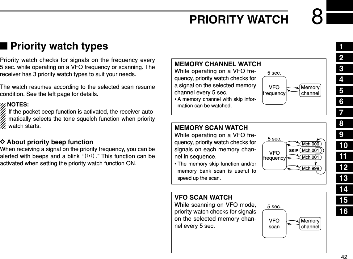
![438PRIORITY WATCH■Priority watch operationDDMemory channel watch and memory scan watchqSelect VFO mode; then, set an operating frequency.wSet the watching channel(s).For memory channel watch:Select the desired memory channel.For memory scan watch:Select memory mode, or the desired bank group; then,push [MODE SCAN] for 1 sec. to start memory/bank scan.ePush [8 SET] for 1 sec. to enter set mode.rRotate [R-DIAL] to select “PRIORITY WATCH” item, thenpush [8 SET].tRotate [R-DIAL] to turn the priority watch ON, then push[8 SET].• Select “BELL” if the priority beep function is necessary.yPush [DUALWATCH] to exit set mode and start the watch.• “PRIO” indicator appears.• The receiver checks the memory/bank channel(s) every 5 sec.• The watch resumes according to the selected scan resume con-dition. (p. 41)uPush [DUALWATCH] to cancel the watch.√µMODEANLAFCPRIOTSQLFM439975PSKIP-DUP001√µMODEANLAFCPRIOTSQLFM145870PSKIP-DUP001√µMODEANLAFCPRIOTSQLFM439975PSKIP-DUP001√µMODEANLAFCPRIOTSQLFM145870PSKIP-DUP001• During priority watchMonitors VFO frequency for 5 sec.Pauses on a memory (bank) channel when a signal is received.• During priority watch with priority beepEmits beep and blinks “S” indicator when a signal is re-ceived on a memory (bank) channel.-NOISE-BLANKER-POWER-SAVE-BACKLIGHT-BEEP-LEVEL-KEY-TOUCH-BEEP>PRIORITY-WATCH----------------PRIORITY-WATCH-BELL>ON-OFF----------------***-SET-MODE-***[R-DIAL]SET8MRS.MWMODESCAN](https://usermanual.wiki/ICOM-orporated/269900/User-Guide-409586-Page-50.png)
![448PRIORITY WATCHDDVFO scan watchqSelect memory mode.• Select a memory bank, if desired.wPush [MODE SCAN] for 1 sec. to start memory/bank scan,if desired.While scanning memory/bank channels:Starts memory/bank scan first. Memory/bank scan can-not be started after VFO scan is started.ePush [8 SET] for 1 sec. to enter set mode.rRotate [R-DIAL] to select “PRIO” item, then push [8 SET].tRotate to turn the priority watch ON, then push [8 SET].• Select “BELL” if the priority beep function is necessary.yPush [DUALWATCH] to exit set mode and start the watch.• “PRIO” indicator appears.uPush and hold [MODE SCAN] to enter scan type selectioncondition.iRotate [R-DIAL] to select the desired scan type from“ALL,” “BAND” and “PROG-xx (xx= 0–24).”oRelease [MODE SCAN] to start the VFO scan watch.• The receiver checks the memory channel(s) every 5 sec.• The watch resumes according to the selected scan resume con-dition. (p. 41)!0Push [DUALWATCH] to cancel the watch and scan.√µMODEANLAFCPRIOTSQLFM1888888PSKIP-DUP001√µMODEANLAFCPRIOTSQLFM145870PSKIP-DUP001√µMODEANLAFCPRIOTSQLFM1888888PSKIP-DUP001√µMODEANLAFCPRIOTSQLFM145870PSKIP-DUP001• During priority watchMonitors VFO frequency for 5 sec.Pauses on a memory (bank) channel when a signal is received.• During priority watch with priority beepEmits beep and blinks “S” indicator when a signal is re-ceived on a memory (bank) channel.12345678910111213141516](https://usermanual.wiki/ICOM-orporated/269900/User-Guide-409586-Page-51.png)
![45COMFORTABLE RECEIVING9■Tone/DTCS squelch operationThe tone or DTCS squelch opens only when receiving a sig-nal with the same pre-programmed subaudible tone or DTCScode, respectively. You can silently wait for the specified sig-nal using the same tone.qSet the desired frequency in FM mode.wWhile pushing [7 TONE], rotate [R-DIAL] to select the de-sired subaudible tone condition from “TSQL,” “TSQLS,”“DTCS” or “DTCSS,” “VSC” and “OFF.”• One of “TSQL,” “ TSQLS,” “DTCS,” “DTCSS” and “VSC”appears according to the tone selection.eWhen a signal with the matched tone is received, thesquelch opens and the receiver emits audio. When pocket beep function is activated, the receiver alsoemits beep tones and blinks “S”.• Beep tones sound and “S” blinks for 30 sec.rPush [DUALWATCH] to stop the beeps and blinking man-ually.•“S” disappears and the pocket beep function is deactivated.tTo cancel the tone squelch or DTCS, rotate [R-DIAL] whilepushing [7 TONE] to tone indication disappears.NOTE: The VSC (Voice Squelch Control) function opensthe squelch only when receiving a modulated signal. Thisfunction is very useful while scanning, the VSC pauses aonly when modulated signals are received. Scanning con-tinues when unmodulated or beat signals are received.MODEAFCTSQLFM-DUPMODEAFCTSQLFM-DUPMODEAFCTSQLFM-DUPMODEAFCDTCSFM-DUPMODEAFCVSCFM-DUPMODEAFCDTCSFM-DUPTone squelch with pocket beep function selectionDTCS selectionVSC selectionDTCS with pocket beep function selectionTone squelch selectionOFF: (No indication)√MODEANLAFCTSQLFM145975PSKIP-DUP“TSQL” appears[R-DIAL]TONE7](https://usermanual.wiki/ICOM-orporated/269900/User-Guide-409586-Page-52.png)
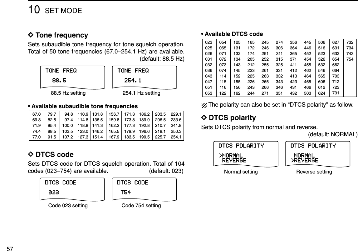
![469COMFORTABLE RECEIVING ■Tone squelch frequency/DTCS code setting88.5 Hz and 023 is set as the default for the tone squelch fre-quency and the DTCS code, respectively. The frequency andcode can be selected as desired.qPush [8 SET] for 1 sec. to enter set mode.wRotate [R-DIAL] to select “SET EXPAND” item, then push[8 SET].eRotate [R-DIAL] to turn the expanded set mode ON, thenpush [8 SET].rRotate [R-DIAL] to select “TONE FREQ” item when se-lecting the tone squelch frequency; select “DTCS CODE”item when selecting the DTCS code, then push [8 SET].tRotate [R-DIAL] to select the desired tone squelch fre-quency or DTCS code, then push [8 SET].• See the tables at right.yPush [DUALWATCH] to exit set mode.•Available tone frequency listNOTE: The receiver has 50 tone frequencies and conse-quently their spacing is narrow compared to units having38 tones. Therefore, some tone frequencies may receiveinterference from adjacent tone frequencies.•Available DTCS code list02302502603103203604304705105312513113213414314515215515616224524625125225526126326526627135636436537141141241342343143250651652352653254656560661262405406507107207307411411511612216517217420521222322522624324427430631131532533133234334635144544645245445546246446546650362763163265466266470371272373173273474375467.069.371.974.477.079.782.585.488.591.594.897.4100.0103.5107.2110.9114.8118.8123.0127.3131.8136.5141.3146.2151.4156.7159.8162.2165.5167.9171.3173.8177.3179.9183.5186.2189.9192.8196.6199.5203.5206.5210.7218.1225.7229.1233.6241.8250.3254.1-BANK-LINK-DTCS-POLARITY-DTCS-CODE>TONE-FREQ-DUPLEX-OFFSET-FREQ----------------TONE-FREQ88.5----------------***-SET-MODE-***-BANK-LINK-DTCS-POLARITY>DTCS-CODE-TONE-FREQ-DUPLEX-OFFSET-FREQ----------------DTCS-CODE023----------------***-SET-MODE-***PushSET8PushSET8Tone squelch frequency selectionDTCS code selection12345678910111213141516](https://usermanual.wiki/ICOM-orporated/269900/User-Guide-409586-Page-53.png)
![479COMFORTABLE RECEIVING■DTCS polarity settingAs well as the code setting, the polarity setting is also avail-able for the DTCS operation. When a different polarity is set,the DTCS never releases audio mute even a signal withmatched code number is received.qPush [8 SET] for 1 sec. to enter set mode.wRotate [R-DIAL] to select “SET EXPAND” item, then push[8 SET].eRotate [R-DIAL] to turn the expanded set mode ON, thenpush [8 SET].rRotate [R-DIAL] to select “DTCS POLARITY” item, thenpush [8 SET].tRotate [R-DIAL] to select the polarity from “NORMAL” and“REVERSE,” then push [8 SET].yPush [DUALWATCH] to exit set mode.DTCS-POLARITY-REVERSE>NORMAL----------------DTCS-POLARITY>REVERSE-NORMAL----------------Normal polarity Reverse polarity-BANK-LINK>DTCS-POLARITY-DTCS-CODE-TONE-FREQ-DUPLEX-OFFSET-FREQ----------------***-SET-MODE-***[R-DIAL]T-SCAN4](https://usermanual.wiki/ICOM-orporated/269900/User-Guide-409586-Page-54.png)
![489TONE SQUELCH AND POCKET BEEP■Tone scanBy monitoring a signal that is being operated with pocketbeep, tone or DTCS squelch function, you can determine thetone frequency or DTCS code necessary to open a squelch.qSet the frequency to be checked for a tone frequency orcode.wTurn the desired tone type, tone squelch or DTCS, ON byholding [7 TONE] with turning [R-DIAL].• One of “TSQL” or “DTCS” appears. • Even the pocket beep function is activated, the function is can-celled when starts the tone scan.ePush [4 T-SCAN] for 1 sec. to start the tone scan.• To change the scanning direction, rotate [R-DIAL].rWhen the CTCSS tone frequency or 3-digit DTCS code ismatched, the squelch opens and the tone frequency orcode is temporarily programmed into the selected condi-tion, such as memory channel.• The tone scan pauses when a CTCSS tone frequency or 3-digitDTCS code is detected.✔For your convenient!Even no tone type is selected, either tone squelch or DTCS,pushing [4 T-SCAN] for 1 sec. also start tone scan. In thiscase, the tone scan searching for tone squelch frequencyonly.☞NOTE: The decoded tone frequency or code is pro-grammed temporarily when a memory channel is se-lected. However, this will be cleared when the memorychannel is re-selected.√188 0√013DTCS scanTone squelch scan[R-DIAL]T-SCAN4TONE712345678910111213141516](https://usermanual.wiki/ICOM-orporated/269900/User-Guide-409586-Page-55.png)
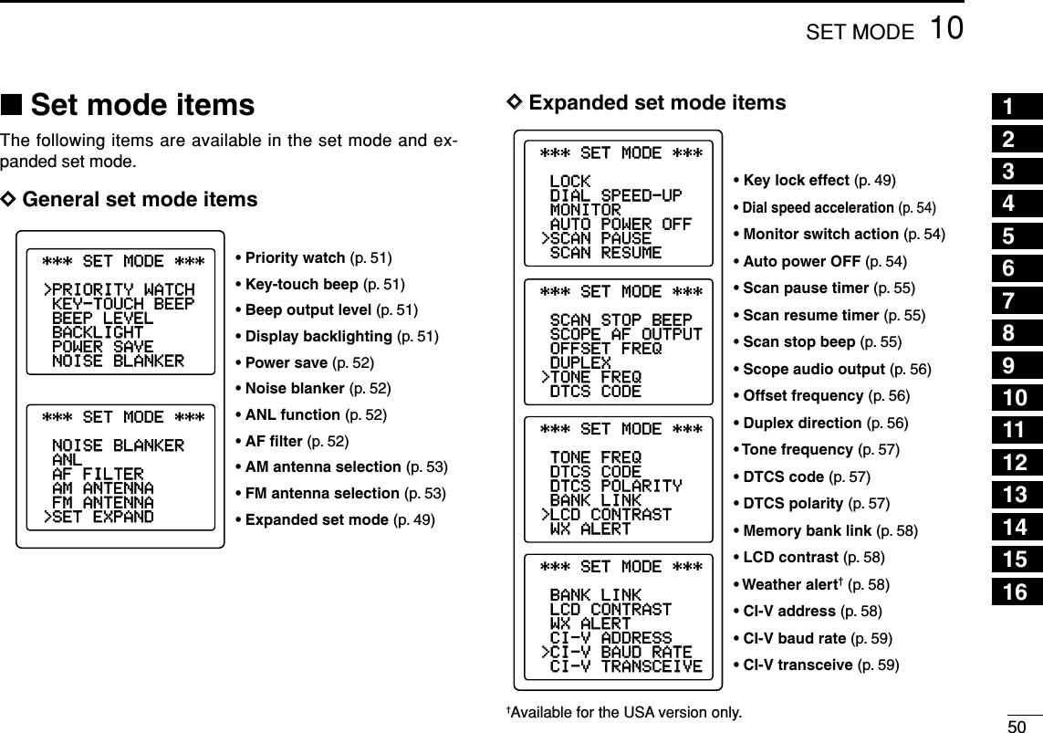
![49SET MODE10■GeneralSet mode is used for programming infrequently changed val-ues or conditions of functions.In addition, the IC-R20 has an expanded set mode which isused for programming even more infrequently changed val-ues or conditions of functions. When turning the expandedset mode OFF, only about one thirds of the set mode itemsare displayed for simple operation.DDSet mode entering and operationqPush [8 SET] for 1 sec. to enter set mode.wRotate [R-DIAL] to select the desired item, then push[8 SET].eRotate [R-DIAL] to select the desired value or condition,then push [8 SET] to return the setting item selectionmode.rPush [DUALWATCH] to exit set mode, or rotate [R-DIAL]to select another set mode item.DDExpanded set mode ON/OFFqPush [8 SET] for 1 sec. to enter set mode.wRotate [R-DIAL] to select “SET EXPAND” item.ePush [8 SET] to enter “SET EXPAND,” rotate [R-DIAL] toselect the expanded set mode ON and OFF, then push[8 SET].rRotate [R-DIAL] to select the desired item.tPush [8 SET] to enter the item, rotate [R-DIAL] to selectthe desired value or condition, then push [8 SET].yPush [DUALWATCH] to exit set mode, or rotate [R-DIAL]to select another item.SET-EXPAND-ON>OFF----------------SET-EXPAND>ON-OFF----------------Expanded set mode OFF Expanded set mode ON***-SET-MODE-***>SET-EXPAND-FM-ANTENNA-AM-ANTENNA-AF-FILTER-ANL-NOISE-BLANKER----------------***-SET-MODE-***-NOISE-BLANKER-POWER-SAVE-BACKLIGHT-BEEP-LEVEL-KEY-TOUCH-BEEP>PRIORITY-WATCH----------------SET-EXPAND-ON>OFF----------------SET-EXPAND>ON-OFF----------------DIAL.SEL SWEEP CENTERT-SCAN SKIP M.NTONE SET TSATT RF GAINIC Recorder1234560789BANDDUALWATCHMAIN/SUBPOWERVFOMHz MODESCAN MRS.MWSCOPELOCKRECAFCSET8DUALWATCH](https://usermanual.wiki/ICOM-orporated/269900/User-Guide-409586-Page-56.png)
![5310 SET MODEDDAM antenna selectionThis setting is activated only for the AM broadcast band,0.495–1.620 MHz (differ according to version) reception.• EXT : Use the antenna connected to the antenna con-nector. (default)• BAR : Use the internal bar antenna for AM broadcastband reception.DDFM antenna selectionThis setting is activated only for the FM broadcast band,76.000–107.995 MHz (differ according to version), recep-tion.• EXT : Use the antenna connected to the antennaconnector. (default)• EARPHONE: Use the connected earphone’s cable asthe antenna for FM broadcast band recep-tion.DDKey lock effectWhile the key lock function is ON, [VOLUME] and [SQL] canstill be accessed. Accessible keys can be set to one of 4groups.[POWER] and [•LOCK] are also accessible during the lock,however, these keys are not effected by this setting.• NORMAL : [VOLUME] and [SQL] are accessible. (default)• NO SQL : [SQL] is accessible. • NO VOL : [VOLUME] are accessible. • ALL : No accessible key is available, except[POWER] and [• LOCK].LOCK-NO-SQL-NORMAL----------------LOCK-NO-SQL-NORMAL>NO-VOL -NO-VOL-ALL >ALL----------------LOCK-NO-SQL>NORMAL----------------LOCK>NO-SQL-NORMAL-NO-VOL -NO-VOL-ALL -ALL----------------Normal lock conditionAudio output can be adjustedSquelch level can be adjustedReceiver power and lockfunction only switchableFM-ANTENNA-EARPHONE>EXT----------------FM-ANTENNA>EARPHONE-EXT----------------External antenna Connected earphone cableAM-ANTENNA-BAR>EXT----------------AM-ANTENNA>BAR-EXT----------------External antenna Internal bar antenna](https://usermanual.wiki/ICOM-orporated/269900/User-Guide-409586-Page-60.png)
![5410SET MODEDDDial speed accelerationThe dial speed acceleration automatically speeds up the tun-ing dial speed when rotating [R-DIAL] rapidly.• OFF : The dial speed acceleration is turned OFF.• ON : The dial speed acceleration is tuned ON. (default)DDMonitor key actionThe monitor key, [SQL], can be set as a ‘sticky’ key. Whenset to the sticky condition, each push of [SQL] toggles themonitor function ON and OFF.• PUSH : Pushing and holding [SQL] to monitor the fre-quency. (default)• HOLD : Push [SQL] momentarily to monitor the fre-quency and push momentarily again to cancel it.DDAuto power OFFThe receiver can be set to automatically turn OFF after aspecified period is past.30 min., 1 hour, 1.5 hours, 2 hours, BUSY and OFF (default)can be specified. The specified period is retained even whenthe receiver is turned OFF by the auto power OFF function.To cancel the function, select “OFF” in this set mode.• 30–120: The receiver automatically turns OFF (with abeep) after a specified period from last key op-eration.• BUSY : The receiver automatically turns OFF (with abeep) after 3 minutes from last key operation orsignal reception.AUTO-POWER-OFF>30MIN-OFF----------------AUTO-POWER-OFF-30MIN-OFF-90MIN-60MIN-90MIN-60MIN-BUSY >BUSY-120MIN -120MIN----------------30 min. timer 2 hrs. timerMONITOR-HOLD>PUSH----------------MONITOR>HOLD-PUSH----------------Push and hold [SQL] to monitorPush to monitorDIAL-SPEED-UP-ON>OFF----------------DIAL-SPEED-UP>ON-OFF----------------The acceleration ONThe acceleration OFF12345678910111213141516](https://usermanual.wiki/ICOM-orporated/269900/User-Guide-409586-Page-61.png)
![5510 SET MODEDDScan pause timerSelects the scan pause time. When receiving signals, thescan pauses according to the scan pause time.• 2–20 : Scan pauses for 2–20 sec. on a received signal,and selected in 2 sec. steps. (default: 10 sec.)• HOLD : Scan pauses on a received signal until it disap-pears. Rotate [R-DIAL] to resume manually.DDScan resume timerSelects scan resume time. Scan resumes after the specifiedperiod when the received signal disappears.• 0 : Scan resumes immediately when the receivedsignal disappears.• 1–5 : Scan pause 1–5 sec. after the received signaldisappears. (default: 2 sec.)• HOLD : Scan pauses on the received signal even if it dis-appears. Rotate [R-DIAL] to resume manually.DDScan stop beepTurns the scan stop beep function ON and OFF. When the function is activated (“ON” is selected), a long beepwill sounds each time when signal is received during scan.SCAN-STOP-BEEP-ON>OFF----------------SCAN-STOP-BEEP>ON-OFF----------------No beep is sound whenreceiving a signalA long beep is sound whenreceiving a signalSCAN-RESUME-1SEC-0SEC----------------SCAN-RESUME-2SEC-1SEC-3SEC>2SEC-4SEC-3SEC-5SEC >HOLD-4SEC -5SEC----------------Scan resumes after 2 sec. Scan resumes manuallySCAN-PAUSE-4SEC-2SEC----------------SCAN-PAUSE-14SEC-12SEC-8SEC-6SEC-18SEC-16SEC-12SEC >HOLD>10SEC -20SEC----------------Scan pauses for 10 sec. Scan pauses until signal disappears](https://usermanual.wiki/ICOM-orporated/269900/User-Guide-409586-Page-62.png)
![5610SET MODEDDScope audio outputSets the audio output function while scope operation.The scope audio output is used for finding out the signalswhile scope function are modulated, unmodulated or beetsignal etc.DDOffset frequencySets the duplex offset frequency for each frequency band in-dependently within 0 to 159.99999 MHz range. During duplexoperation (–DUP or +DUP), the monitoring frequency (while[SQL] is pushed) shifts the set frequency. The default value may differ according to the selected fre-quency band (before accessing set mode) and receiver version.The selected tuning step in VFO mode is used for the off-set frequency setting.DDDuplex directionSets the duplex direction. The displaying frequency shifts theprogrammed offset frequency (at left below) when monitorfunction is in use (while pushing [SQL]).• OFF : Simplex operation. (default)• –DUP : The displaying frequency shifts down dur-ing monitor.• +DUP : The displaying frequency shifts up duringmonitor.DUPLEX--DUP>OFF-+DUP----------------DUPLEX--DUP-OFF>+DUP----------------Simplex operation Positive duplex operationOFFSET-FREQ----0.000.00OFFSET-FREQ159.999.99---------------- --------------------------------SCOPE-AF-OUTPUT-ON>OFF----------------SCOPE-AF-OUTPUT>ON-OFF--------------------------------No audio output whilesweep operationAF output whilesweep operation12345678910111213141516](https://usermanual.wiki/ICOM-orporated/269900/User-Guide-409586-Page-63.png)
![5810SET MODE12345678910111213141516DDMemory bank link Sets the linked bank for the bank-link scan.(default: All banks are ON)qRotate [R-DIAL] to select the bank that you want to changesetting.wPush [8 SET] for 1 sec. to enter the bank link setting con-dition.eRotate [R-DIAL] to select the setting, then push [8 SET].rRotate [R-DIAL] to select next bank and repeat qto e, orpush [DUALWATCH] to exit set mode.DDLCD contrastThe LCD contrast can be adjusted through 15 levels.DDWeather alert functionTurns weather alert function ON and OFF.WX-ALERT-ON>OFF----------------WX-ALERT>ON-OFF----------------Weather alert OFF Weather alert ONU.S.A. version onlyLCD-CONTRASTLCD-CONTRASTMinimum level Maximum levelBANK-A-ON>OFF----------------BANK-A>ON-OFF----------------When OFF is selected When ON is selectedBANK-A-ON>OFF----------------BANK-A>ON-OFF----------------BANK-LINK-BANK-B:ON>BANK-A:ON-----------------BANK-D:ON-BANK-C:ON-BANK-F:ON-BANK-E:ON](https://usermanual.wiki/ICOM-orporated/269900/User-Guide-409586-Page-65.png)
![6011OTHER FUNCTIONS■Antenna selectionThe IC-R20 has an internal bar antenna for receiving AMbroadcast band (0.495–1.620 MHz) signals. In addition, theconnected earphone’s cable can be used as an antenna forreceiving FM broadcast band (76.000–107.995 MHz; differ ac-cording to version) signals.DDSelecting antennaqPush [8 SET] for 1 sec. to enter set mode.wRotate [R-DIAL] to select “AM ANTENNA” or “FM AN-TENNA” item for AM broadcast band or FM broadcastband, respectively.eAfter pushing [8 SET], rotate [R-DIAL] to select “BAR”when “AM ANTENNA” is selected for the AM broadcastband; select “EARPHONE” when “FM ANTENNA” is se-lected for the FM broadcast band.yPush [DUALWATCH] momentarily to exit set mode.NOTE:•Some noise or spurious may be received when the inter-nal bar or earphone cable is used for antenna.• The supplied or third party’s antenna MUST BE con-nected to the antenna connector to receive signals otherthan AM or FM broadcast bands.• When receiving an AM broadcast signal with internal barantenna, aim the receiver to better audio direction.• When the internal bar or earphone cable is used for an an-tenna, the attenuator function cannot be used.>BAR-EXT----------------AM-ANTENNA>EARPHONE-EXT----------------FM-ANTENNABar antenna selection for 0.495–1.620 MHz bandEarphone cable selection for 76.000–107.995 MHz band***-SET-MODE-***-BAR>EXT----------------AM-ANTENNA-SET-EXPAND-FM-ANTENNA>AM-ANTENNA-AF-FILTER-ANL-NOISE-BLANKER----------------[R-DIAL]DUALWATCHSET812345678910111213141516](https://usermanual.wiki/ICOM-orporated/269900/User-Guide-409586-Page-67.png)
![6111 OTHER FUNCTIONSDDWeather channel selectionqPush [MR S.MW] several times to select the weather chan-nel group.wRotate [R-DIAL] to select the desired weather channel. rPush [VFO MHz] to return to VFO mode, or push [MRS.MW] to select other mode to exit the weather channel.DDWeather alert functionNOAA broadcast stations transmit weather alert tones beforeimportant weather announcements. When the weather alertfunction is turned ON, the selected weather channel is moni-tored each 5 sec. for the announcement. When the alert signalis detected, the “ALT” and the “WX” indications are displayedalternately and sounds a beep tone until the receiver is oper-ated. The previously selected (used) weather channel ischecked periodically during standby or while scanning.qSelect the desired weather channel.wTurn the weather alert function ON in set mode.➥Push [8 SET] for 1 sec. to enter set mode.➥Rotate [R-DIAL] to select “WX ALERT” item, then push[8 SET]. Rotate [R-DIAL] to select “ON.”➥Push [DUALWATCH] to exit set mode.eSet the desired stand-by condition.• Select VFO or memory channel.• Scan or priority watch operation can also be selected.rWhen the alert is detected, a beep sounds and the follow-ing indication will be displayed.tTurn the weather alert function OFF in set mode.√MODE ANLAFCTSQLFMPSKIP-DUPWX√MODE ANLAFCTSQLFMPSKIP-DUPALT1 1Show above indications alternately.√MODE ANLAFCTSQLFM1PSKIP-DUPWXWeather channel indication[R-DIAL]MRS.MWVFOMHz■Weather channel operation U.S.A. version only](https://usermanual.wiki/ICOM-orporated/269900/User-Guide-409586-Page-68.png)
![6311 OTHER FUNCTIONSDCloning error☞NOTE: DO NOT push any key on the sub-receiver duringcloning. This will cause a cloning error.When the display appears as below, a cloning error has oc-curred.In such a case, the receiver automatically performs ALLRESET while turning power OFF and ON. ■Auto power-off functionThe IC-R20 can be set to automatically turn OFF after a spec-ified period in which no operation is performed.BUSY, 120 min., 90 min., 60 min., 30 min. and OFF can bespecified. The specified period is retained even when the re-ceiver is turned OFF by the auto power-off function. To cancelthe function, select “OFF” in step ebelow.qPush [8 SET] for 1 sec. to enter set mode.wRotate [R-DIAL] to select “AUTO POWER OFF” item, thenpush [8 SET].• Turn the expanded set mode ON for selection. (p. 49)eRotate [R-DIAL] to select the desired time or to turn thefunction OFF, then push [8 SET].rPush [DUALWATCH] to exit set mode.***-SET-MODE-***-SCAN-PAUSE>AUTO-POWER-OFF-MONITOR----------------AUTO-POWER-OFF>BUSY-120MIN-90MIN-60MIN-30MIN-OFF----------------[R-DIAL]DUALWATCHSET8USINGEXPANDED SET MODE√MODE ANLAFCTSQLFM146010PSKIP-DUPALL-RESETCLONE-ERRORTurn power OFF, then ON](https://usermanual.wiki/ICOM-orporated/269900/User-Guide-409586-Page-70.png)
![6411OTHER FUNCTIONS■IC recorderThe IC-R20 has an IC recorder of up to 32 tracks. The maxi-mum recording length is about 260 minutes.DDRecording a received audioqPush [ REC] momentarily to start recording.• Red LED below the [ REC] lights ON.wPush [ REC] momentarily to pause to record or push[■≈≈]to stop recording.DDPlaying recorded audioqPush [ΩΩΩΩATT]/[≈≈≈≈RF GAIN] to select the desired track.• The track number appears.wPush [■≈≈]momentarily to start playing the track.ePush [ΩΩΩΩATT] when you want to rewind; or [≈≈≈≈RFGAIN] when you want to skip while playing.rPush [■≈≈]to stop playing.• Even you don’t push [■≈≈], the receiver stops automatically andreturns to normal condition at the end of the track.VOLTRACK:01NORMAL---------------0:00:30/0:12:14x1.00---------------81VOLTRACK:01NORMAL---------------0:00:30/0:12:14x1.00---------------81VOL√MODE ANLAFCTSQLFMREC145780P S KIP-DUP√MODE ANLAFCTSQLFMREC145780P S KIP-DUP√MODE ANLAFCTSQLFMSTOP145780P S KIP-DUP√MODE ANLAFCTSQLFMSTOP145780P S KIP-DUPTRACK:06TRACK:01NORMAL---------------0:00:32/0:12:14x1.00---------------VOLTRACK:01NORMAL---------------0:00:30/0:12:14x1.00---------------81VOLTRACK:01NORMAL---------------0:00:30/0:12:14x1.00---------------81√MODE ANLAFCTSQLFM145780P S KIP-DUPVOLTRACK:01NORMAL---------------0:00:32/0:12:14x1.00---------------VOL√MODE ANLAFCTSQLFMREC145780P S KIP-DUP√MODE ANLAFCTSQLFMREC145780P S KIP-DUP√MODE ANLAFCTSQLFMSTOP145780P S KIP-DUP√MODE ANLAFCTSQLFMSTOP145780P S KIP-DUPTRACK:06TRACK:01NORMAL---------------0:00:32/0:12:14x1.00---------------VOLTRACK:01NORMAL---------------0:00:30/0:12:14x1.00---------------81VOLTRACK:01NORMAL---------------0:00:30/0:12:14x1.00---------------81√MODE ANLAFCTSQLFM145780P S KIP-DUPTRACK:06√MODE ANLAFCTSQLFM145780PSKIP-DUPVOL√MODE ANLAFCTSQLFMREC145780P S KIP-DUP√MODE ANLAFCTSQLFMREC145780P S KIP-DUP√MODE ANLAFCTSQLFMSTOP145780P S KIP-DUP√MODE ANLAFCTSQLFMSTOP145780P S KIP-DUPTRACK:06TRACK:01NORMAL---------------0:00:32/0:12:14x1.00---------------VOLTRACK:01NORMAL---------------0:00:30/0:12:14x1.00---------------81VOLTRACK:01NORMAL---------------0:00:30/0:12:14x1.00---------------81√MODE ANLAFCTSQLFM145780P S KIP-DUPATT RF GAINIC RecorderRECThe track number appearsRECTRACK:01√MODE ANLAFCTSQLFM145780PSKIP-DUP√PSKIPRECVOL√MODE ANLAFCTSQLFMREC145780P S KIP-DUP√MODE ANLAFCTSQLFMREC145780P S KIP-DUP√MODE ANLAFCTSQLFMSTOP145780P S KIP-DUP√MODE ANLAFCTSQLFMSTOP145780P S KIP-DUPTRACK:01NORMAL---------------0:00:32/0:12:14x1.00---------------VOLTRACK:01NORMAL---------------0:00:30/0:12:14x1.00---------------81VOLTRACK:01NORMAL---------------0:00:30/0:12:14x1.00---------------81Red LEDRest of recording time bar appears12345678910111213141516](https://usermanual.wiki/ICOM-orporated/269900/User-Guide-409586-Page-71.png)
![6511 OTHER FUNCTIONS• Playing speed settingThe playing speed can be selected from 5 speeds.qPush [■≈≈]for 1 sec. to enter the playing speed set mode.wRotate [R-DIAL] to select the desired speed, then push[■≈≈].DDRecording set mode• Quality settingqPush [ REC] for 1 sec. to enter the recording set mode.wRotate [R-DIAL] to select “QUALITY,” then push [8 SET].eRotate [R-DIAL] to select the recording quality, then push[ REC].rPush [DUALWATCH] momentarily to exit the recording setmode.NOTE:The IC recorder can store 32 tracks at the maximum.When the 32nd track is recorded, the recording function isnot available even recording time is left. At this time deleteall recorded contents (see the next page) or transfer therecorded contents to PC using optional CS-R20 CLONINGSOFTWARE.*****-REC--*****-REC-REMOTE>QUALITY-ALL-DELETE----------------QUALITY-NORMAL>LONG-TIME-FINE----------------VOL√MODE ANLAFCTSQLFMREC145780P S KIP-DUP√MODE ANLAFCTSQLFMREC145780P S KIP-DUP√MODE ANLAFCTSQLFMSTOP145780P S KIP-DUP√MODE ANLAFCTSQLFMSTOP145780P S KIP-DUPTRACK:06TRACK:01NORMAL---------------0:00:32/0:12:14x1.00---------------VOLTRACK:01NORMAL---------------0:00:30/0:12:14x1.00---------------81VOLTRACK:01NORMAL---------------0:00:30/0:12:14x1.00---------------81√MODE ANLAFCTSQLFM145780P S KIP-DUPPLAYBACK-SPEED-x0.75-x0.50-x1.25>x1.00-x1.50----------------VOL√MODE ANLAFCTSQLFMREC145780P S KIP-DUP√MODE ANLAFCTSQLFMREC145780P S KIP-DUP√MODE ANLAFCTSQLFMSTOP145780P S KIP-DUP√MODE ANLAFCTSQLFMSTOP145780P S KIP-DUPTRACK:06TRACK:01NORMAL---------------0:00:32/0:12:14x1.00---------------VOLTRACK:01NORMAL---------------0:00:30/0:12:14x1.00---------------81VOLTRACK:01NORMAL---------------0:00:30/0:12:14x1.00---------------81√MODE ANLAFCTSQLFM145780P S KIP-DUPSelection Recording Recording TimeQuality (Approx.)LONG TIME Low 260 min.NORMAL Normal 130 min.FINE High 65 min.](https://usermanual.wiki/ICOM-orporated/269900/User-Guide-409586-Page-72.png)
![6611OTHER FUNCTIONS12345678910111213141516• Automatic recordingThe IC-R20 has an automatic recording function. When thisfunction is activated, the receiver will record automaticallywhen a receiving signal appears and pause when the signaldisappears. This function is very useful when you want tostore an uncontinuous signal.qPush [ REC] for 1 sec. to enter the recording set mode.wRotate [R-DIAL] to select “REC REMOTE” item, then push[8 SET].eRotate [R-DIAL] to select the setting, then push [ REC].rPush [DUALWATCH] momentarily to exit the recording setmode.• Erasing recorded audioNOTE:The IC recorder can erase the all tracks at the same time,but cannot erase each track independently. Only using theoptional CS-R20 CLONING SOFTWAREcan store therecorded audio into a PC or erase independently.qPush [ REC] for 1 sec. to enter the recording set mode.wRotate [R-DIAL] to select “ALL DELETE” item, then push[ REC].eRotate [R-DIAL] to select “YES” if you want to delete alltracks, then push [ REC].• After deleting, the receiver returns to normal operating mode.*****-REC--*****-REC-REMOTE-QUALITY>ALL-DELETE----------------ALL-DELETE>YES-NO----------------VOL√MODE ANLAFCTSQLFMREC145780P S KIP-DUP√MODE ANLAFCTSQLFMREC145780P S KIP-DUP√MODE ANLAFCTSQLFMSTOP145780P S KIP-DUP√MODE ANLAFCTSQLFMSTOP145780P S KIP-DUPTRACK:06TRACK:01NORMAL---------------0:00:32/0:12:14x1.00---------------VOLTRACK:01NORMAL---------------0:00:30/0:12:14x1.00---------------81VOLTRACK:01NORMAL---------------0:00:30/0:12:14x1.00---------------81√MODE ANLAFCTSQLFM145780P S KIP-DUP*****-REC--*****>REC-REMOTE-QUALITY-ALL-DELETE----------------REC-REMOTE>ON-OFF----------------VOL√MODE ANLAFCTSQLFMREC145780P S KIP-DUP√MODE ANLAFCTSQLFMREC145780P S KIP-DUP√MODE ANLAFCTSQLFMSTOP145780P S KIP-DUP√MODE ANLAFCTSQLFMSTOP145780P S KIP-DUPTRACK:06TRACK:01NORMAL---------------0:00:32/0:12:14x1.00---------------VOLTRACK:01NORMAL---------------0:00:30/0:12:14x1.00---------------81VOLTRACK:01NORMAL---------------0:00:30/0:12:14x1.00---------------81√MODE ANLAFCTSQLFM145780P S KIP-DUP](https://usermanual.wiki/ICOM-orporated/269900/User-Guide-409586-Page-73.png)
![6711 OTHER FUNCTIONS■Partial resetIf you want to initialize the operating conditions (VFO fre-quency, VFO settings, set mode contents) without clearingthe memory contents, a partial resetting function is availablefor the receiver.➥While pushing [VFO MHz], turn the power ON to partiallyreset the receiver.■All resetThe function display may occasionally display erroneous in-formation (e.g. when first applying power). This may becaused externally by static electricity or by other factors.If this problem occurs, turn power OFF. After waiting a fewseconds, turn power ON again. If the problem persists, per-form the following procedure.• Partial resetting is also available. See left for details.IMPORTANT!:Resetting the receiver CLEARS all memory informationand initializes all values in the receiver, including TV chan-nel skip setting.➥While pushing [VFO MHz] and [MR S.MW], turn the powerON to reset the CPU.DIAL.SEL SWEEP CENTERT-SCAN SKIP M.NTONE SET TSATT RF GAINIC Recorder1234560789BANDDUALWATCHMAIN/SUBPOWERVFOMHz MODESCAN MRS.MWSCOPELOCKRECAFC√MODE ANLAFCTSQLFM146010PSKIP-DUPALL-RESET*The appearing frqeuency is differ according to receiver version. VFOMHzMRS.MWPOWERATPOWER ONDIAL.SEL SWEEP CENTERT-SCAN SKIP M.NTONE SET TSATT RF GAINIC Recorder1234560789BANDDUALWATCHMAIN/SUBPOWERVFOMHz MODESCAN MRS.MWSCOPELOCKRECAFC√MODE ANLAFCTSQLFM146010PSKIP-DUP*The appearing frqeuency is differ according to receiver version. VFOMHzPOWERATPOWER ON](https://usermanual.wiki/ICOM-orporated/269900/User-Guide-409586-Page-74.png)
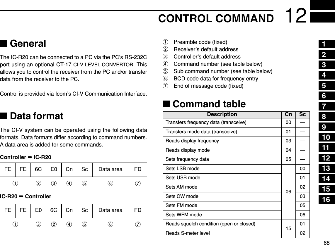
![6912 CONTROL COMMANDCT-17Power supply9–15VDCRS-232CcableIC-R20to [SP/CI-V]ComputerOptionalBC-25CI-V connection example3.5(d) mmGNDI/OGNDI/O3.5(d) mm stereo plug must be used.](https://usermanual.wiki/ICOM-orporated/269900/User-Guide-409586-Page-76.png)
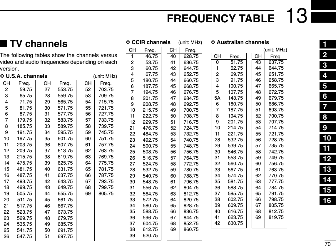
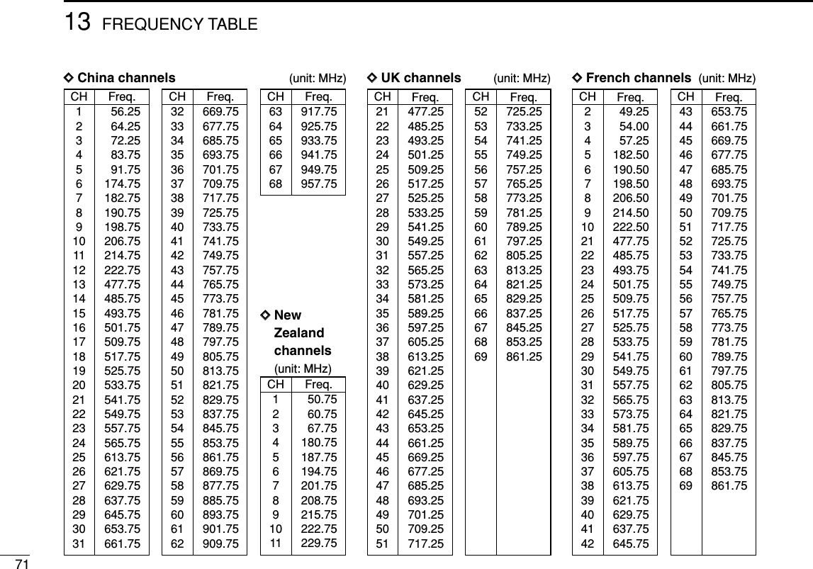
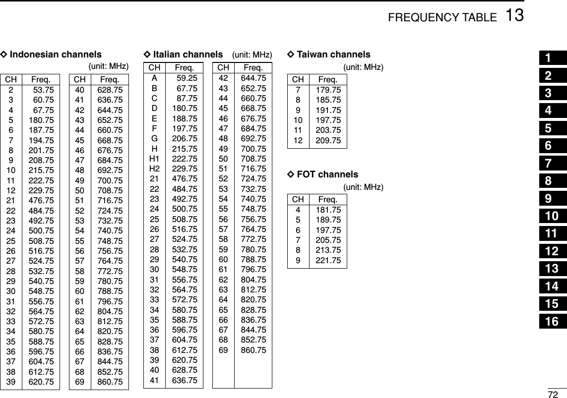
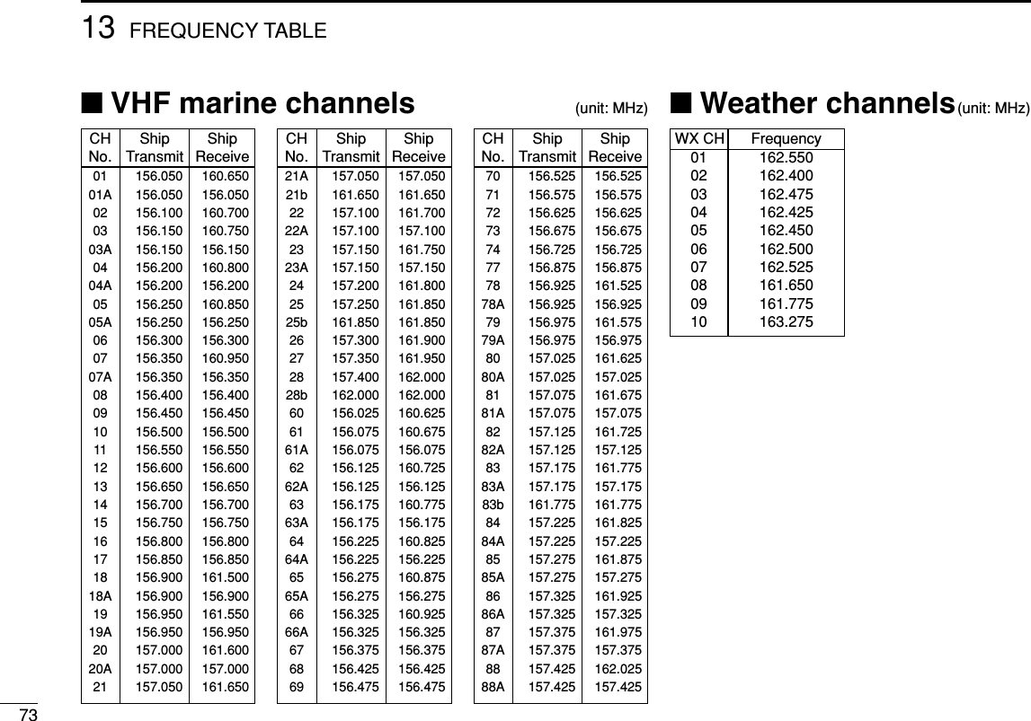
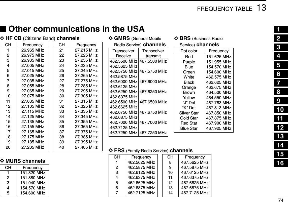
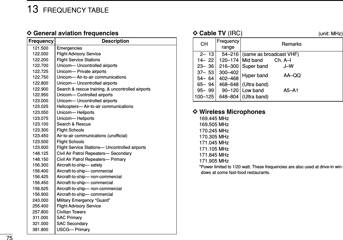
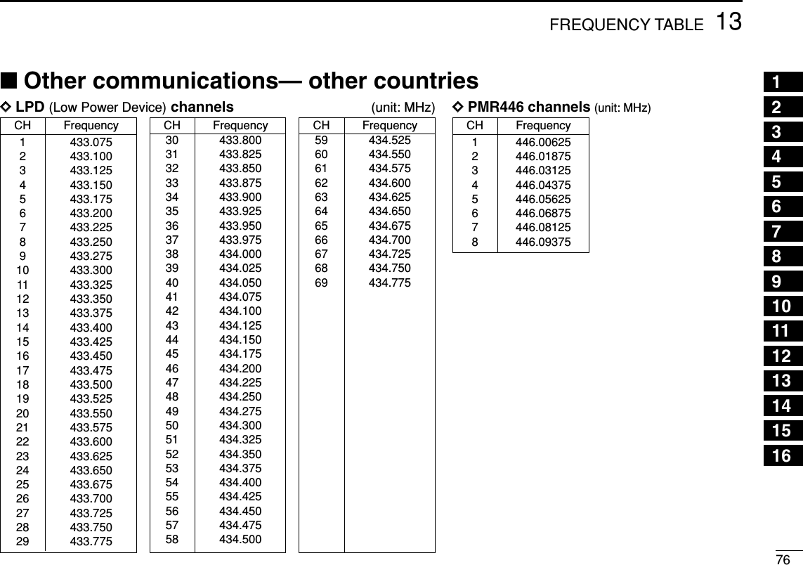
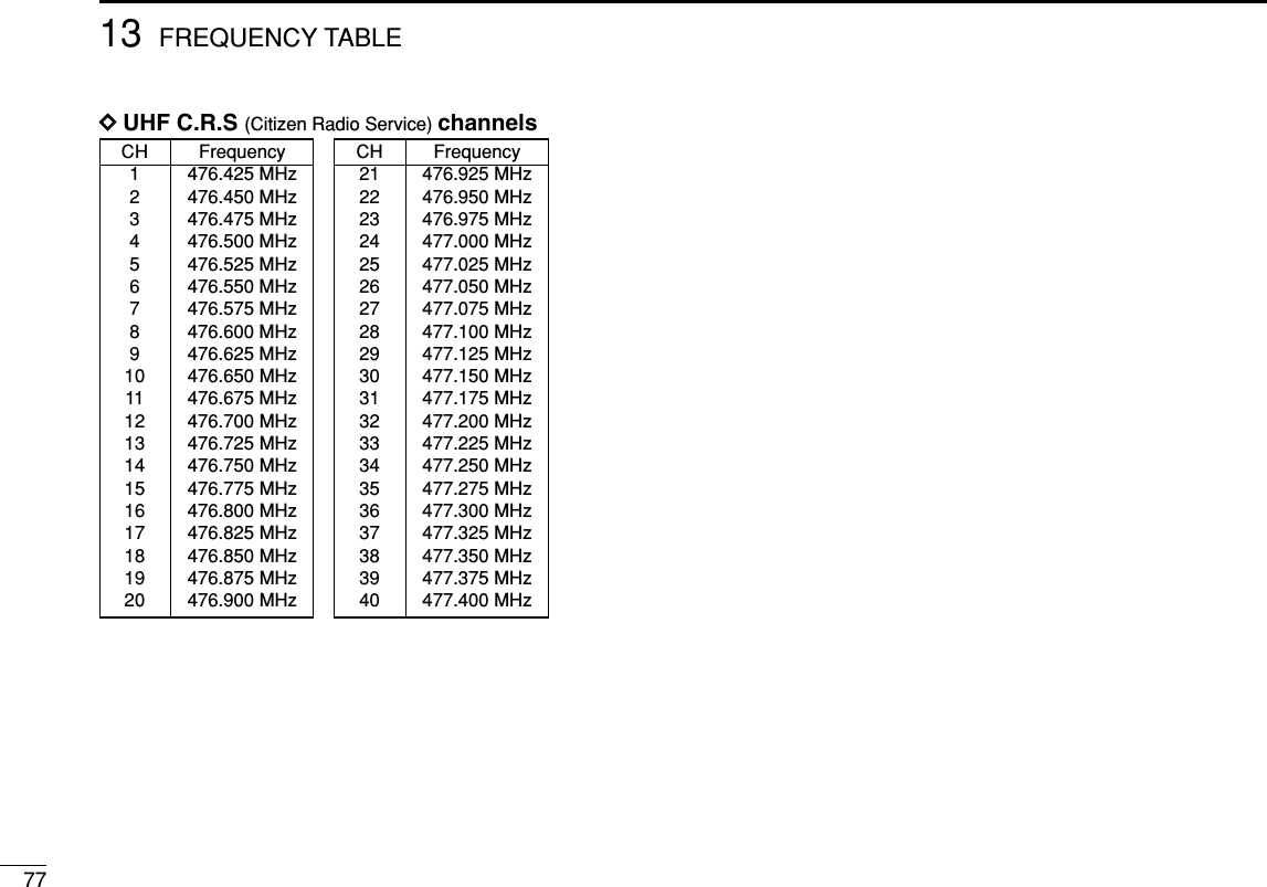
![7814MAINTENANCEPROBLEM POSSIBLE CAUSE SOLUTION REF.■Troubleshooting If your receiver seems to be malfunctioning, please check thefollowing points before sending it to a service center.No power comes on.No sound comes from thespeaker.Sensitivity is low and onlystrong signals are audible.Frequency cannot be set.No beep sound.Receive audio is distorted.Desired set mode itemcannot be selected.Programmed scan doesnot start.Memory or bank scandoes not start.• The batteries are exhausted.• The battery polarity is reversed.• Volume level is too low.• Squelch level is set too tight.• Different tone is selected with tone squelch.• Attenuator function is activated.• RF gain setting is too low for SSB/CW modes.• The lock function is activated.• Beep tones are turned OFF or the beep tone levelis too low.• The operating mode is not selected correctly.• “EXPAND” item is set to OFF.• Program scan edges are not programmed.• No or only one memory or bank channel is pro-grammed.• Replace the batteries or charge the battery pack.• Check the battery polarity. • Rotate [R-DIAL] or push [Y] to obtain a suitable level.• While pushing [SQL], rotate [R-DIAL] to set thesquelch level.• Turn the appropriate function OFF.• Push [ATT] for 1 sec. to turn the attenuator functionOFF.• Push [RF GAIN] for 1 sec., then rotate [R-DIAL] toselect “MAX” level.• Push [• LOCK] for 1 sec. to turn the function OFF.• Turn beep tone ON or set the beep tone level to ap-propriate level in set mode.• Push [MODE•SCAN] several times to select a suit-able operating mode.• Turn “EXPAND” item ON.• Program a pair of scan edge channels.• Program at least 2 memory or bank channelspgs. 8–10p. 8p. 17p. 18p. 45p. 19p. 19p. 16p. 51p. 16p. 49p. 36pgs. 26,2712345678910111213141516](https://usermanual.wiki/ICOM-orporated/269900/User-Guide-409586-Page-85.png)