ICOM orporated 269900 Amateur UHF Scanning Receiver User Manual
ICOM Incorporated Amateur UHF Scanning Receiver
User Manual
INSTRUCTION MANUAL
iR20
COMMUNICATIONS RECEIVER
This device complies with Part 15 of the FCC rules. Operation is sub-
ject to the following two conditions: (1) This device may not cause
harmful interference, and (2) this device must accept any interference
received, including interference that may cause undesired operation.
WARNING: MODIFICATION OF THIS DEVICE TO RECEIVE CEL-
LULAR RADIO TELEPHONE SERVICE SIGNALS IS PROHIBITED
UNDER FCC RULES AND FEDERAL LAW.
i
FOREWORD
Thank you for purchasing this Icom product. The IC-R20
COM
-
MUNICATIONS RECEIVER
is designed and built with Icom’s supe-
rior technology and craftsmanship. With proper care, this
product should provide you with years of trouble-free operation.
We want to take a couple of moments of your time to thank you
for making your IC-R20 your radio of choice, and hope you
agree with Icom’s philosophy of “technology first.” Many hours of
research and development went into the design of your IC-R20.
DD
FEATURES
❍Covers 0.150–3304.999 MHz* wide
frequency range
*Some frequency bands are inhibited according to version
❍External power supply operation
❍1250 memory channels* with 26 banks
available
*200 auto write and 50 scan edge channels are included.
❍Built-in bar-antenna
❍
Dualwatch operation
IMPORTANT
READ ALL INSTRUCTIONS carefully and completely
before using the receiver.
SAVE THIS INSTRUCTION MANUAL— This in-
struction manual contains important operating instructions for
the IC-R20.
EXPLICIT DEFINITIONS
WORD DEFINITION
RWARNING!
CAUTION
NOTE
Personal injury, fire hazard or electric shock
may occur.
Equipment damage may occur.
Recommended for optimum use. No risk of
personal injury, fire or electric shock.
Icom, Icom Inc. and the logo are registered trademarks of Icom
Incorporated (Japan) in the United States, the United Kingdom, Ger-
many, France, Spain, Russia and/or other countries.

RWARNING! NEVER operate the receiver with a ear-
phone, headphones or other audio accessories at high vol-
ume levels. Hearing experts advise against continuous high
volume operation. If you experience a ringing in your ears, re-
duce the volume level or discontinue use.
RWARNING! NEVER connect the receiver to an AC
outlet. This may pose a fire hazard or result in an electric
shock.
RWARNING! NEVER operate the receiver while dri-
ving a vehicle. Safe driving requires your full attention—any-
thing less may result in an accident.
RWARNING! NEVER throw a battery cell or battery
pack into a fire since as internal battery gas can cause explo-
sion.
RWARNING! NEVER disassemble the battery pack.
If the battery cell’s internal material (electrolyte liquid) gets
into your eyes, wash your eyes with water and obtain treat-
ment from an eye doctor immediately.
NEVER connect the receiver to a power source of more
than 6 V DC directly. This will damage the receiver.
NEVER connect the receiver to a power source using re-
verse polarity. This will damage the receiver.
NEVER expose the receiver to rain, snow or any liquids.
The receiver may be damaged.
NEVER operate or touch the receiver with wet hands. This
may result in an electric shock or damage the receiver.
NEVER solder the battery cell. This may damage the bat-
tery.
AVOID using or placing the receiver in direct sunlight or in
areas with temperatures below –10°C (+14˚F) or above
+60°C (+140˚F).
AVOID the use of chemical agents such as benzine or al-
cohol when cleaning, as they can damage the receiver’s sur-
faces.
Even when the receiver power is OFF, a slight current still
flows in the circuits. Remove batteries from the receiver when
not using it for a long time. Otherwise, the installed batteries
will become exhausted, and will need to be recharged.
RESPECT other peaple’s privacy. Information overheard
but not intended for you cannot lawfully be used in any way.
For U.S.A. only
CAUTION: Changes or modifications to this device, not ex-
pressly approved by Icom Inc., could void your authority to
operate this device under FCC regulations.
ii
PRECAUTION
iii
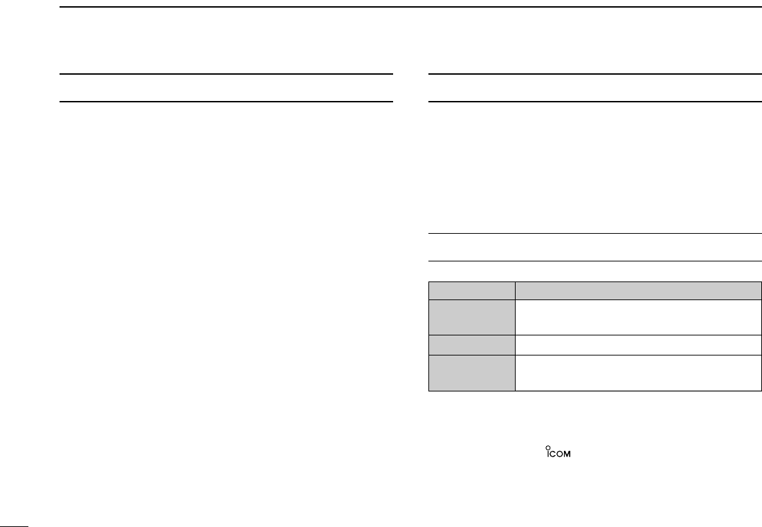
SUPPLIED ACCESSORIES
qAntenna (FA-B04RE) ………………………………………1
wBelt clip (MB-98)…………………………………………1 set
eBattery spacer ………………………………………………1
rHand strap …………………………………………………1
tBattery pack* (BP-206) ……………………………………1
yAC adaptor*(BC-149A/D) …………………………………1
(The shape of the BC-149A and BC-149D are different.)
*Not supplied with some versions.
OPERATING THEORY
Electromagnetic radiation which has frequencies of
20,000 Hz (20 kHz*) and above is called radio frequency (RF)
energy because it is useful in radio transmissions. The IC-
R20 receives RF energy from 0.150 MHz* to 3304.999 MHz
and converts it into audio frequency (AF) energy which in turn
actuates a loudspeaker to create sound waves. AF energy is
in the range of 20 to 20,000 Hz.
*kHz is an abbreviation of kilohertz or 1000 hertz, MHz is abbreviation
of megahertz or 1,000,000 hertz, where hertz is a unit of frequency.
OPERATING NOTES
The IC-R20 may receive its own oscillated frequency, result-
ing in no reception or only noise reception, on some frequen-
cies.
The IC-R20 may receive interference from extremely strong
signals on different frequencies or when using an external
high-gain antenna.
qw e
y
r
t

iv
TABLE OF CONTENTS 1
2
3
4
5
6
7
8
9
10
11
12
13
14
15
FOREWORD .................................................. i
IMPORTANT .................................................. i
EXPLICIT DEFINITIONS ................................ i
PRECAUTION ............................................... ii
SUPPLIED ACCESSORIES ......................... iii
OPERATING THEORY ................................. iii
OPERATING NOTES ................................... iii
TABLE OF CONTENTS ................................ iv
QUICK REFERENCE GUIDE .................. I–VI
■Preparation ............................................. I
1 PANEL DESCRIPTION ........................ 1–7
■Front, top and side panels .................... 1
■Function display .................................... 6
2 BATTERY CHARGING ...................... 8–10
■Battery installation ................................. 8
■Caution .................................................. 9
■Battery charging .................................... 9
3 FREQUENCY AND CHANNEL SETTING
.......................................................... 11–16
■Mode selection..................................... 11
■Operating band selection..................... 12
■Setting a tuning step............................ 14
■Setting a frequency.............................. 14
■Selecting a memory channel ............... 10
■Receive mode selection ...................... 16
■Lock function ....................................... 16
4 BASIC OPERATION ........................ 17–23
■Receiving............................................. 17
■Setting audio volume ........................... 17
■Squelch level setting............................ 18
■Monitor function ................................... 18
■Attenuator function .............................. 19
■RF gain ................................................ 19
■Duplex operation ................................. 20
■AFC function........................................ 21
■NB/ANL functions ................................ 21
■Band scope.......................................... 22
■[DIAL] function assignment.................. 23
5 DUALWATCH OPERATION ............ 24–25
■Setting audio volume ........................... 24
■Squelch level setting............................ 24
■Main band selection............................. 25
■Band exchange.................................... 25
6 MEMORY CHANNELS ..................... 26–33
■General description ............................. 26
■Memory channel programming............ 26
■Memory bank setting ........................... 27
■Memory bank selection........................ 28
■Programming memory/bank name ...... 29
■Selecting memory/bank name indication..... 30
■Copying memory contents................... 31
■Memory clearing .................................. 32
■Erasing/transferring bank contents...... 33
7 SCAN OPERATION ......................... 34–41
■Scan types........................................... 34
■Full/band/programmed scan................ 35
■Scan edges programming ................... 36
■Memory/bank/all bank scan................. 37
■Auto-memory write scan...................... 38
■Skip channel/frequency setting............ 39
■Scan resume condition ........................ 40
7 PRIORITY WATCH .......................... 42–44
■Priority watch types ............................. 42
■Priority watch operation ....................... 43
9 COMFORTABLE RECEIVING.......... 45–48
■Tone/DTCS squelch operation............. 45
■Tone squelch frequency/DTCS code set-
ting....................................................... 46
■DTCS polarity setting........................... 47
■Tone scan ............................................ 48
10 SET MODE ...................................... 49–59
■General................................................ 49
■Set mode items.................................... 50
11 OTHER FUNCTIONS ....................... 60–67
■Antenna selection ................................ 60
■Weather channel operation ................. 61
■Data cloning ........................................ 62
■Auto power-off function........................ 63
■IC recorder........................................... 64
■Partial reset ......................................... 67
■All reset ............................................... 68
12 CONTROL COMMAND ................... 68–69
■General................................................ 68
■Data format.......................................... 68
■Command table ................................... 68
13 FREQUENCY TABLE ...................... 70–61
■TV channels......................................... 70
■VHF marine channels .......................... 73
■Weather channels................................ 73
■Other communications in the USA ...... 74
■Other communications— other countries
............................................................. 76
14 MAINTENANCE ..................................... 78
■Troubleshooting ................................... 78
15 SPECIFICATIONS ................................. 79
16 OPTIONS ............................................... 80
16
I
QUICK REFERENCE GUIDE
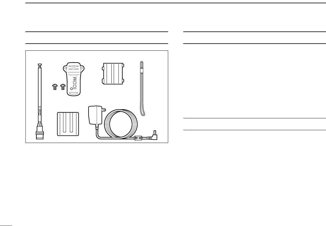
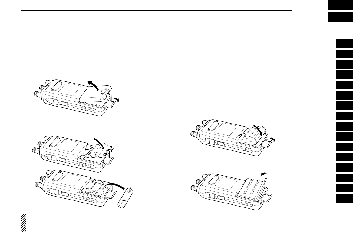
■Preparation
DBattery installation
qRemove the battery cover from the receiver.
wInstall 3 R6(AA) size alkaline cell batteries.
• Be sure to observe the correct polarity.
Keep battery the contacts clean. It’s a good idea to clean
the battery terminals once a week.
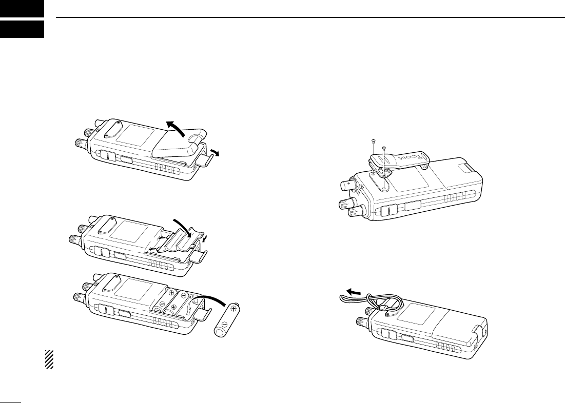
DBelt clip
Conveniently attaches to your belt.
Attach the belt clip using the supplied screws.
DHandstrap
Slide the handstrap through the loop on the top of the rear
panel as illustrated at below. Facilities carrying.
q
w
e
II
QUICK REFERENCE GUIDE
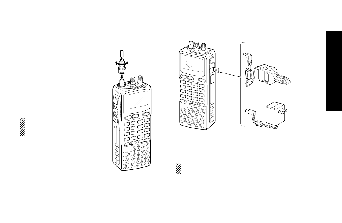
DDAntenna
Insert the supplied antenna into the
antenna connector and screw down
the antenna as shown at right.
NEVER hold the antenna when car-
rying the receiver.
Keep the jack cover attached when
jack is not in use to protect the con-
nectors from dust and moisture.
✔
For your information
Third-party antennas may in-
crease receiver performance.
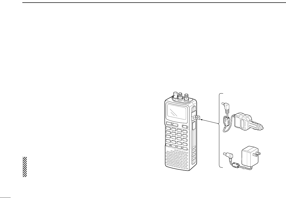
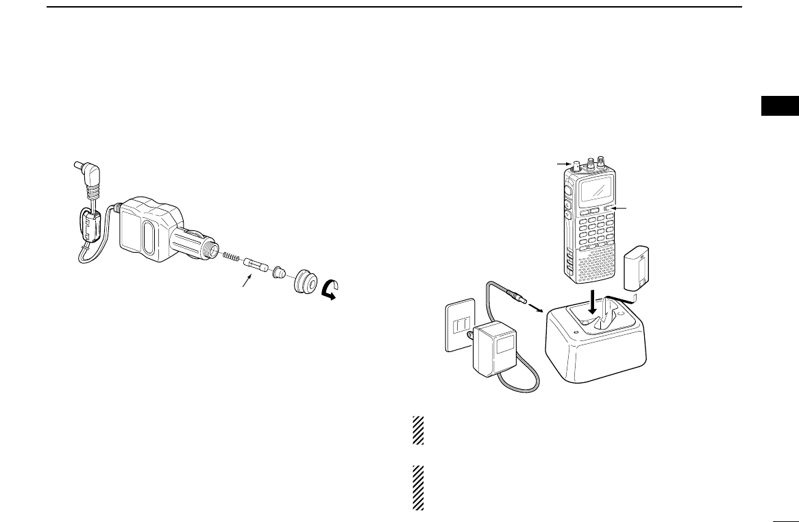
DCharging the battery
qInstall the battery pack (BP-206).
wPlug the AC adaptor into an AC outlet.
eInsert the adaptor plug into the [DC] jack of the receiver.
RRWARNING!:
NEVER charge the alkaline batteries.
IC-R20
to [DC]
jack
Optional CP-18A/E
Cigarette lighter cable
with DC-DC converter
AC adapter
BC-149A/D
to cigarette
lighter socket
to AC outlet
Quick reference guide
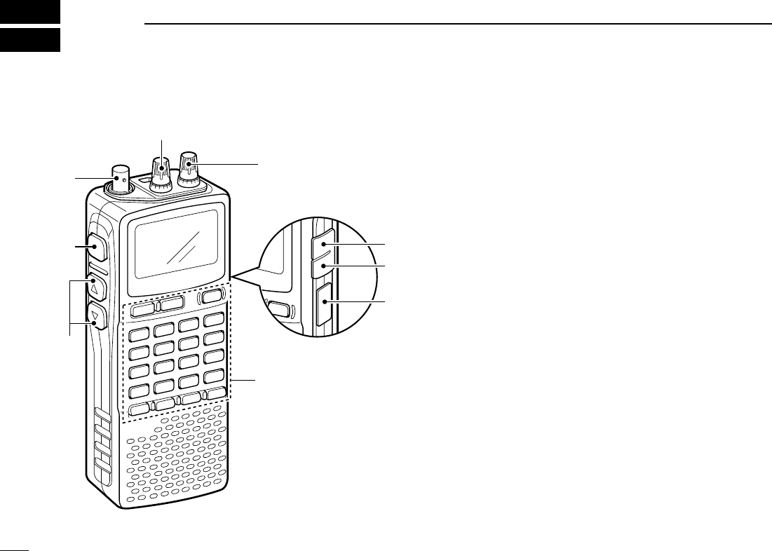
■Front, top and side panels
qANTENNA CONNECTOR (p. II)
Connects the supplied antenna.
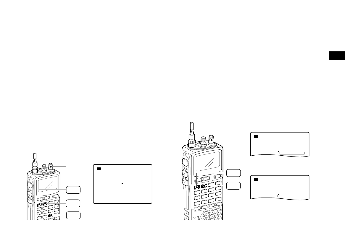
wSQUELCH KEY [SQL] (p. 18)
➥Push and hold to temporarily open the squelch and
monitor the operating frequency.
➥While pushing this key, rotate the tuning dial* to adjust
the squelch level.
eUP/DOWN KEYS [YY]/[ZZ]
Adjust audio volume level.* (p. 17)
rUSB JACK [USB]
Connect a PC via the optional OPC-1382 CLONING
CABLE for Data/Audio cloning.
tEXTERNAL DC-IN CONNECTOR [DC] (p. 9)
Connects an AC adaptor or an optional cigarette lighter
cable for both charging the installed re-chargeable battery
pack and operating.
yEXTERNAL SPEAKER CONNECTOR [SP/CI-V]
➥Connect an optional earphone or headphone.
The internal speaker will not function when any exter-
nal equipment is connected. (See p. 80 for a list of
available options.)
➥Connect an optional CT-17 for remote control operation.
(p. 68)
q
w
e
r
t
y
u
i
KEYPAD
1
PANEL DESCRIPTION
1
2
1
PANEL DESCRIPTION
1
uLEFT DIAL [L-DIAL]
➥During single band operation, rotate to adjust audio vol-
ume level.* (p. 17)
➥During dualwatch operation, activates as the tuning dial
for upper side on the display.*
iRIGHT DIAL [R-DIAL]
➥Rotate to select the operating frequency.* (p. 12)
➥While scanning, changes the scanning direction.*
(p. 26)
➥While pushing [SQL], sets the squelch level.* (p. 18)
➥While pushing [VFO MHz], sets the operating frequency
in 1 MHz or 10 MHz in VFO mode.* (p. 14)
➥While pushing [BAND], selects the operating band in
VFO mode.* (p. 14)
➥While dualwatch operation, activates as the tuning dial
for lower side on the display.* (p. 14)
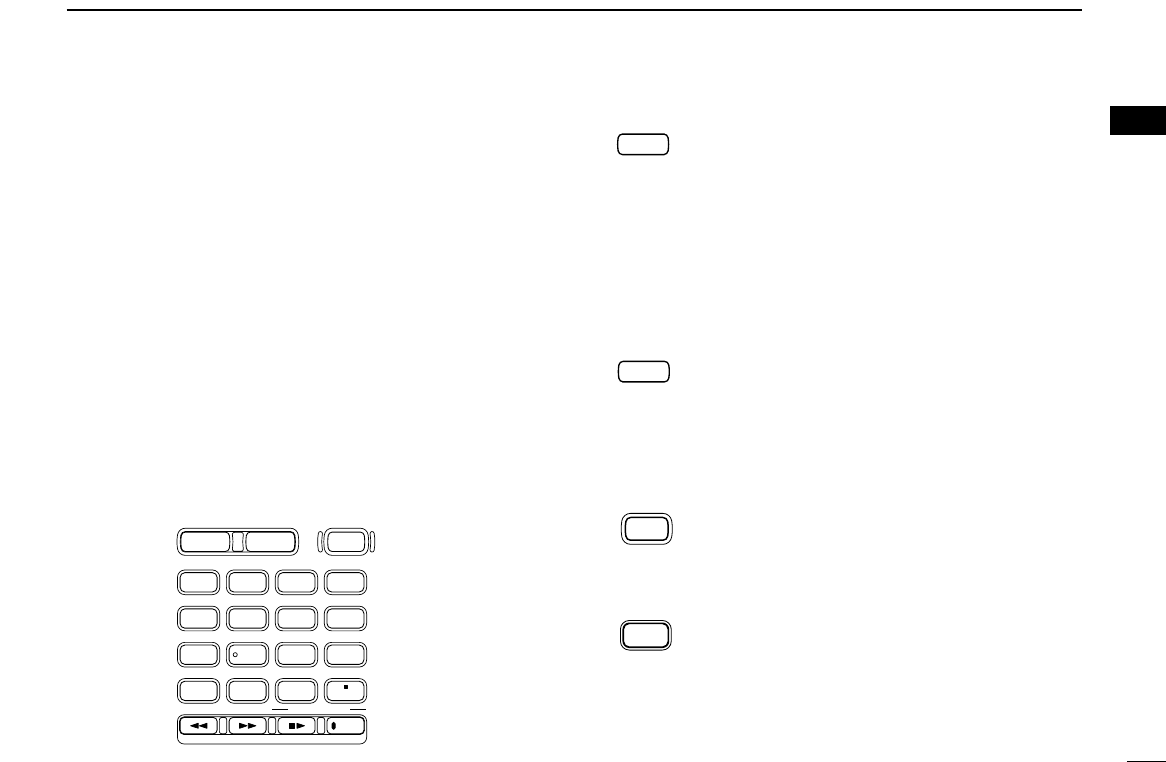
KEYPAD
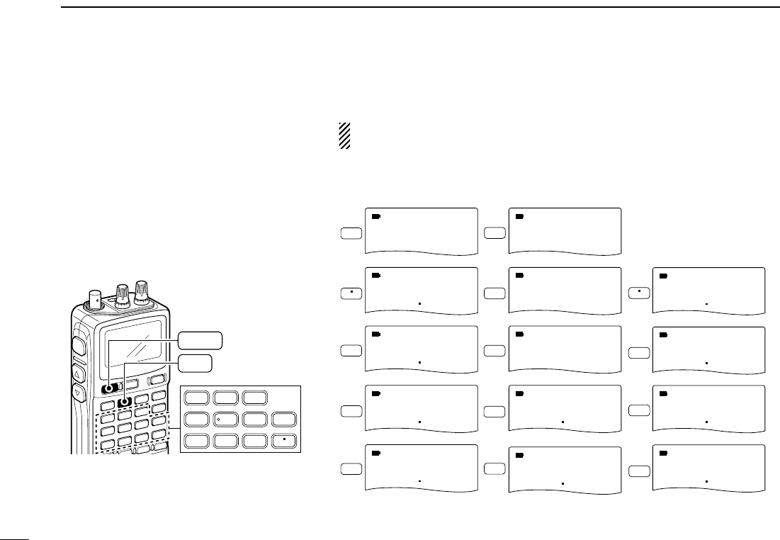
qDUALWATCH/CLEAR KEY [DUALWATCH]
➥Push for 1 sec. to toggle between single band
and dualwatch operation. (p. 24)
➥Clears numeric key input. (p. 15)
➥Returns to previous operating condition while
setting frequency or memory channel, or while
in set mode.
➥Cancels the band scope or scan function.
(pgs. 22, 35)
wMAIN/SUB KEY [MAIN/SUB] (p. 25)
➥During dualwatch operation, push to select the
MAIN band or SUB band.
➥During dualwatch operation, push for 1 sec. to
exchange the upper frequency and lower fre-
quency.
ePOWER KEY [PWR]
Push for 1 sec. to turn the receiver power ON
and OFF.
rBAND KEY [BAND]
➥Push to select the operating frequency band.
(p. 14)
BAND
POWER
MAIN/SUB
DUALWATCH
DIAL.SEL SWEEP CENTER
T-SCAN SKIP M.N
TONE SET TS
ATT RF GAIN
IC Recorder
123
4560
789
BAND
DUALWATCH
MAIN/SUB
POWER
VFO
MHz MODE
SCAN MR
S.MW
SCOPE
LOCK
REC
AFC
*The function of tuning control ([DIAL]) and volume control ([Y]/[Z])
can be traded. See page 23 for details.

3
1PANEL DESCRIPTION
tVFO/MHz KEY [VFO MHz]
➥Push to select VFO mode. (p. 11)
➥Push for 1 sec. to toggle between the 1 MHz
or 10 MHz tuning steps (p. 14
yMODE/SCAN KEY [MODE SCAN]
➥Push to select the operating mode (FM, WFM,
AM, USB, LSB, CW). (p. 16)
➥Push for 1 sec. to start a scan. (p. 35)
uMEMORY KEY [MR S.MW]
➥Push to select between memory mode, TV
channel and PreSet channel. (p. 11)
➥Push for 1 sec. to enter memory write condi-
tion. (p. 26)
➥Push for 2 sec. to write the operating fre-
quency into the selected memory channel in
VFO mode.
Push [MR S.MW] for 2 sec. to transfer the dis-
played frequency into the VFO in memory
mode. (p. 31)
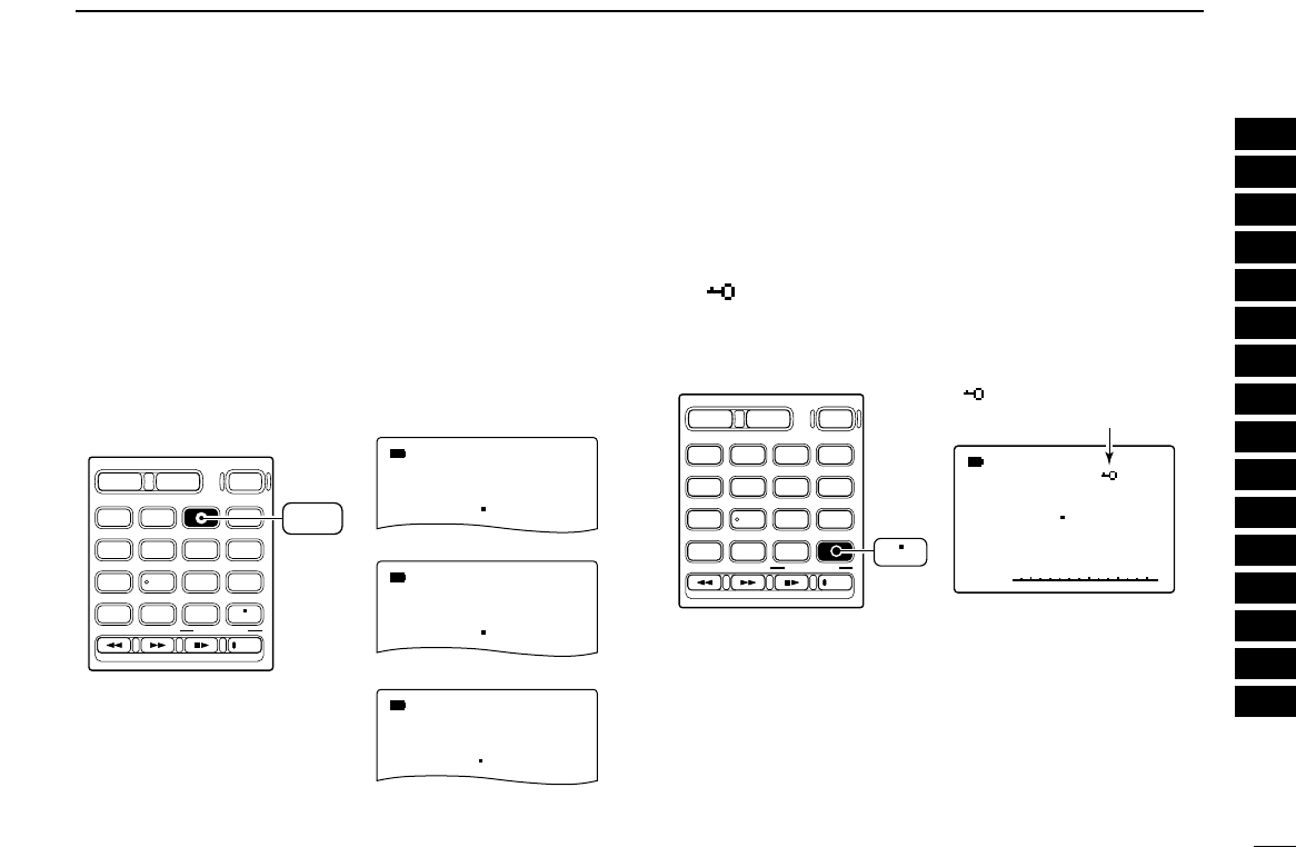
iVOLUME/DIAL KEY [1 DIAL SEL]
➥Inputs digit ‘1’ for frequency input, memory
channel selection, etc.
➥Push for 1 sec. to trade the volume control ([L-
DIAL], [Y]/[Z]) and tuning control ([R-DIAL])
functions. (p. 23)
•√é appears when the [Y]/[Z]keys function as
a volume control.
oSWEEP KEY [2 SWEEP] (p. 22)
➥Inputs digit ‘2’ for frequency input, memory
channel selection, etc.
➥Push for 1 sec. to select the tuning step for
band scope function. Once a pushing this key,
the band scope function sweeps once via the
new tuning step.
!0 CENTER KEY [3 CENTER] (p. 22)
➥Inputs digit ‘3’ for frequency input, memory
channel selection, etc.
➥Push for 1 sec. to return the display frequency
of the band frequency.
!1 SCOPE KEY [SCOPE] (p. 22)
➥Push to activate the band scope function dur-
ing normal operating condition. Or push to
stop continuous sweeping.
➥Push for 1 sec. to start a continuous sweep-
ing.
SCOPE
CENTER
SWEEP
DIAL SEL
MR
S.MW
MODE
SCAN
VFO
MHz
4
1
PANEL DESCRIPTION
1
2
3
4
5
6
7
8
9
10
11
12
13
14
15
16
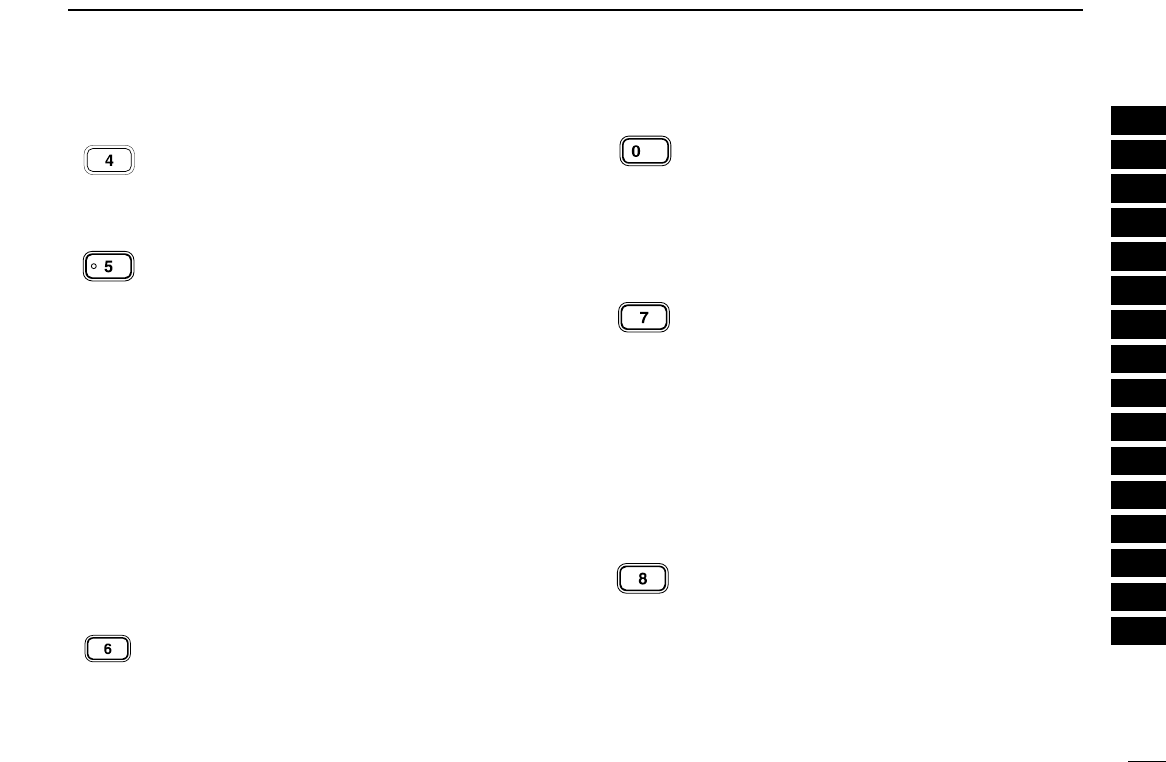
!2 TONE SCAN KEY [4 T-SCAN]
➥Inputs digit ‘4’ for frequency input, memory
channel selection, etc.
➥Push for 1 sec. to start a tone scan. (p. 48)
!3 FREQUENCY SKIP KEY [5 SKIP]
➥Inputs digit ‘5’ for frequency input, memory
channel selection, etc.
➥Push for 1 sec. to turn the frequency skip
function ON and OFF in VFO mode. (p. 39)
• “PSKIP” appears when the frequency skip function
is in use.
➥Push for 1 sec. to set the memory channel as
the following skip channel in memory mode in
order. (p. 39)
• Skip channel — “SKIP” appears.
• Frequency skip channel — “PSKIP” appears.
• Non-skip channel — no skip indicator appears.
➥Push for 1 sec. to program a paused fre-
quency as a skip frequency while scanning.
(p. 39)
!4 MEMORY NAME KEY [6 M.N]
➥Inputs digit ‘6’ for frequency input, memory
channel selection, etc.
➥Push for 1 sec. to turn the memory name indi-
cation ON and OFF. (p. 30)
!5 AFC KEY [0 AFC]
➥Inputs digit ‘0’ for frequency input, memory
channel selection, etc.
➥Push for 1 sec. to turn the AFC (Automatic
Frequency Control) function ON and OFF.
(p. 21)
!6 TONE SQUELCH KEY [7 TONE]
➥Inputs digit ‘7’ for frequency input, memory
channel selection, etc.
➥Push for 1 sec. to activate the following tone
squelch functions in order.
• Tone squelch — “TSQL” appears. (p. 46)
• Pocket beep — “TSQLS” appears. (p. 46)
• DTCS squelch — “DTCS” appears. (p. 46)
• DTCS beep — “DTCSS” appears. (p. 46)
• VSC function — “VSC” appears. (p. 46)
• No tone operation — no tone indicator appears.
!7 SET MODE KEY [8 SET]
➥Inputs digit ‘8’ for frequency input, memory
channel selection, etc.
➥Push for 1 sec. to enter the set mode.
SET
TONE
AFC
M.N
SKIP
T SCAN
5
1PANEL DESCRIPTION
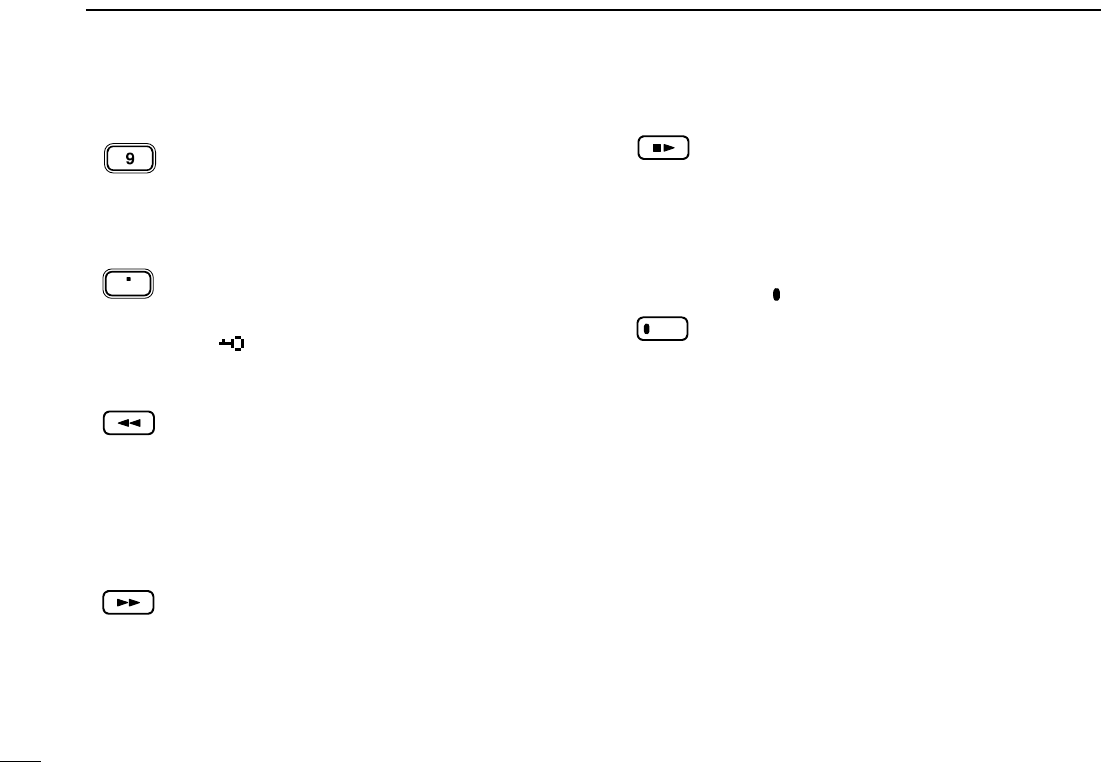
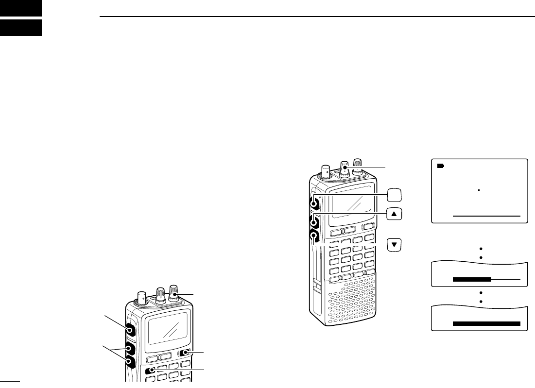
!8 TUNING STEP KEY [9 TS]
➥Push for 1 sec. to select the tuning step.
(p. 14)
➥Inputs digit ‘9’ for frequency input, memory
channel selection, etc.
!9 LOCK KEY [• LOCK]
➥Inputs MHz digit for frequency input. (p. 15)
➥Push for 1 sec. to toggle the lock function ON
and OFF. (p. 16)
• “ ” appears while the key lock function is in use.
@0 REWIND/ATTENUATOR KEY [
ΩΩΩΩ
ATT]
➥Push to select the track for recorded audio.
(p. 64)
➥Push and hold to rewind during playing the
recorded audio. (p. 64)
➥Push for 1 sec. to turn the attenuator function
ON and OFF during normal operation. (p. 19)
@1 SKIP/RF GAIN KEY [
≈≈≈≈
RF GAIN]
➥Push to select the track for recorded audio.
(p. 64)
➥Push and hold to skip the recorded audio.
(p. 64)
➥Push for 1 sec. to enter the RF GAIN set
mode. Push to select the item after selecting
with [R-DIAL]. (p. 19)
@2 STOP/PLAY [■
≈≈
]
➥Push to start the recorded audio. (p. 64)
➥Push to stop the recording or playing audio.
(p. 64)
➥Push for 1 sec. to enter the play speed set
mode. Push to select the item after selecting
with [R-DIAL]. (p. 65)
@3 RECORD KEY [ REC]
➥Push for 1 sec. to enter the record set mode.
Push to select the item after selecting with [R-
DIAL]. (p. 65)
➥Push to start recording audio. (p. 64)
➥Push to pause recording audio. (p. 64)
REC
RF GAIN
ATT
LOCK
TS
6
1
PANEL DESCRIPTION
1
2
3
4
5
6
7
8
9
10
11
12
13
14
15
16
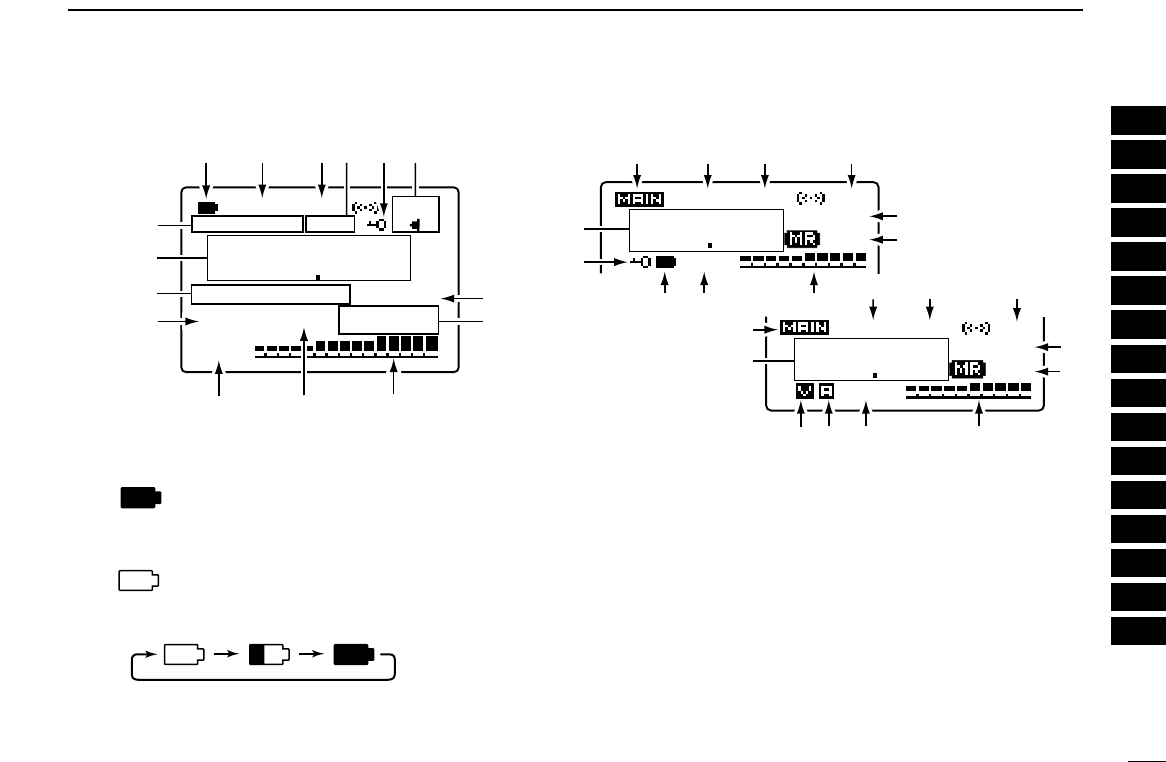
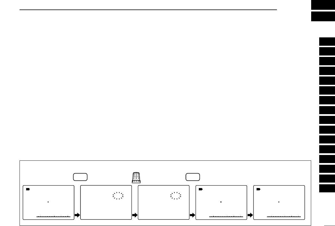
■Function display
qBATTERY INDICATOR
➥“ ” appears when the installed batteries have
ample capacity.
• They do not appear when operating with an external power
source.
➥“ ” appears when the batteries are nearing ex-
haustion.
➥Scrolls while charging the installed BP-206. (p. 8)
➥Battery indicator blinks when completely charged.
wDUPLEX INDICATORS (p. 20)
“+DUP” appears when plus semi-duplex, “–DUP” appears
when minus semi-duplex (repeater) operation is selected.
eSIGNAL SQUELCH INDICATORS
➥“TSQL” appears while the tone squelch function is in
use. (p. 46)
➥“DTCS” appears while the DTCS squelch function is in
use. (p. 46)
➥“S” appears with the “TSQL” or “DTCS” indicator
while the pocket beep function (with CTCSS or DTCS) is in
use. (p. 46)
➥“VSC” appears while the VSC (Voice Squelch Control)
function is in use. (p. 46)
145000
433000
-DUP
-DUP
FM
TSQL
TSQL
PS
PS
PRIO
PRIO
FM
000
000
ATT
M:Amature2
√
µ
MODE
AFC
AFC
PRI
RI
O
TSQL
TSQL
FM
145000
PSKIP
-DUP
000
000
q
q
w
w
w
e
e
e
tr
t
y
!6
u
u
u
i
i
i
o
o
o
!0
!0
!0
!1
!1
!2
!2
!5
!4
!3
!6
!5
!4
!4
!5
ANL

7
1PANEL DESCRIPTION
rANL/NB INDICATOR (pgs. 21, 52)
➥“ANL” appears when the ANL (Automatic Noise Limitter)
function is in use. The ANL function is available only for
AM mode.
➥“NB” appears when the noise blanker function is in use.
The noise blanker function is available while in
LSB/USB/CW modes.
tLOCK INDICATOR (p. 16)
Appears when the lock function is activated.
yAFC INDICATOR (p. 21)
Appears when the lock function is activated.
• The AFC function is available for single band operation only.
uSKIP INDICATORS (p. 39)
➥“SKIP” appears when the selected memory channel is
specified as a skip channel.
➥“PSKIP” appears when the displayed frequency is spec-
ified as a skip frequency.
iCHANNEL SECTION INDICATOR (p. 11)
➥“µ” and three digits channel number appear when
memory channel is selected.
➥“å” and three digits channel number appear when
auto-memory write channel is selected.
➥“TV” appears when TV channel is selected.
➥“WX”* appears when weather channel is selected.
*Available for the USA version only. “ å” and “TV” indi-
cations appear for single band operation only.
oSIGNAL STRENGTH INDICATOR
Shows the receivng signals relative to signal strength.
!0PRIORITY WATCH INDICATOR (p. 42)
Appears when priority watch is in use.
!1ATTENUATOR INDICATOR (p. 19)
Appears when the RF attenuator is in use.
!2VOLUME/DIAL EXCHANGE INDICATOR (p. 23)
➥“ √” appears when the normal operation.
➥“ ∂” appears when the functions of the tuning con-
trol and volume control are traded.
!3MEMORY/BANK NAME INDICATOR
Shows the memory name or bank name.
• This indication is available when memory name or bank name is
programmed.
!4FREQUENCY READOUT
Shows an operating frequency.
• The smaller readout appears at right when tuning step is se-
lected 0.1 kHz or 0.01 kHz steps.
• The decimal point blinks during scan.
!5RECEIVE MODE INDICATOR (p. 16)
Shows the selected receive mode.
• FM, WFM AM, LSB, USB and CW are available.
!6MAIN BAND INDICATOR (p. 24)
Shows the main band on upper display or lower display.
• This indication appears only when dualwatch operation.
8
2
BATTERY CHARGING
1
2
3
4
5
6
7
8
9
10
11
12
13
14
15
16
■Battery installation
Before installing, or replacing the batteries, push [POWER]
for 1 sec. to turn the power OFF.
qRemove the battery cover from the receiver.
wInstall 3 R6 (AA) size alkaline batteries.
• Be sure to observe the correct polarity.
Keep the battery contacts clean to avoid rust or poor con-
tact. It’s a good idea to clean the battery terminals once a
week.
DDBattery pack installation
qRemove the battery cover from the receiver.
wRemove the supplied battery spacer for R6 (AA) size bat-
tery use.
eInstall the Li-Ion battery pack (BP-206).
• Be sure to observe the correct direction.
• Charge Li-Ion battery pack before use.
•Battery pack installation
•Battery pack removal
q
w
e
■Caution
DDBattery caution
•CAUTION! NEVER short the battery terminals. Also, current
may flow into nearby metal objects such as a necklace, so
be careful when placing battery pack in handbags, etc.
•NEVER incinerate used battery pack or battery cells. Inter-
nal battery gas may cause explosion.
•NEVER mix old and new batteries.
•Make sure all battery cells are the same brand, type and
capacity.
Either of the above may cause a fire hazard or damage the
receiver if ignored.
DDCharging caution
• Recommended temperature for charging:
±0˚C to +35˚C (; +32˚F to +95˚F)
• Connect the supplied (or optional for some versions) AC
adaptor or optional cigarette lighter cable only when charg-
ing the battery pack (BP-206). NEVER use other manufac-
ture’s chargers.
CAUTION: BE SURE to disconnect the CP-18A/E from
the cigarette lighter socket when charging is finished, be-
cause, a slight current still follows in the CP-18A/E and the
vehicle’s battery will become exhausted.
■Battery charging
DDRegular charging
qAttach the battery pack (BP-206) to the receiver. (See
page 8)
wPlug the AC adaptor (BC-149A/D*) into an AC outlet; or the
optional CP-18A/E into a cigarette lighter socket.
* Not supplied with some versions.
eInsert the adaptor plug into [DC] of the receiver.
•Charging periods: 8 hours (w/BP-206)
IC-R20
to [DC]
jack
Optional CP-18A/E
Cigarette lighter cable
with DC-DC converter
AC adapter
BC-149A/D
to cigarette
lighter socket
to AC outlet
9
2BATTERY CHARGING
10
2
BATTERY CHARGING
2
DDCP-18A/E fuse replacement
If the fuse blows or the receiver stops functioning while oper-
ating with the optional CP-18A/E, find the source of the prob-
lem if possible, and replace the damaged fuse with a new
rated one (FGB 5 A) as shown below.
DDRapid charging with the BC-156
The optional BC-156 provides rapid charging of battery
packs.
•Charging periods: 2.5 hours (w/BP-206)
CAUTION: Shorten or remove the telescoping antenna be-
fore charging to prevent the receiver from overturning.
If the charge indicator flashes orange, there may be a
problem with the battery pack (or charger). Reinsert the
battery pack or contact your dealer.
Turn power OFF.
BC-156
Check the
orientation.
Shorten or remove
the antenna.
Fuse 5 A
11
FREQUENCY AND CHANNEL SETTING
3
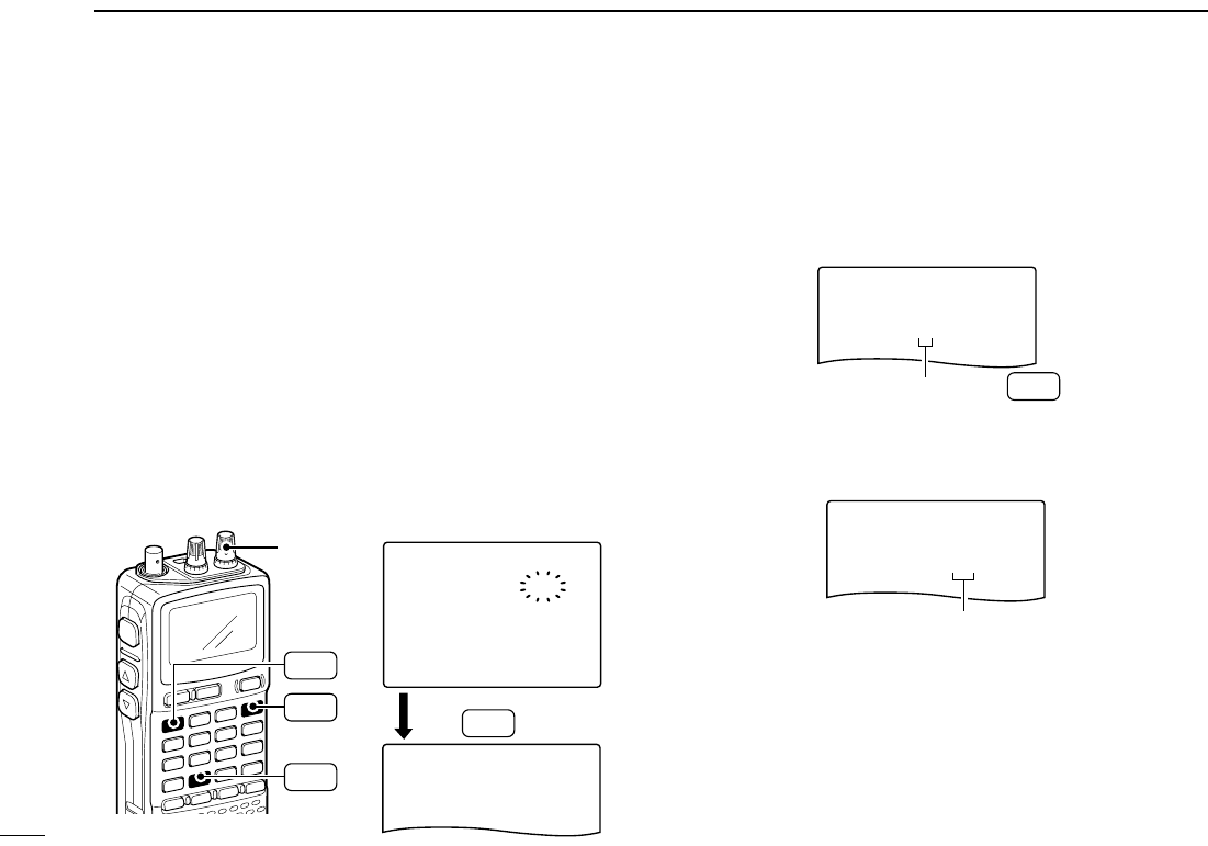
■Mode selection
DDVFO mode
VFO mode is used for the desired frequency setting within the
frequency coverage.
➥Push [VFO MHz] to select VFO mode.
What is VFO?
VFO is an abbreviation of Variable Frequency Oscillator. Fre-
quencies for receiving are generated and controlled by the
VFO.
DDMemory mode/PreSet*/TV*/Weather†channels
Memory mode is used for operation of memory channels
which have programmed frequencies. PreSet channels are
used for most-often used frequencies for quick recall.
*Appears only when PreSet channels/TV channels are
programmed via the optional CS-R20.
†Available for the USA version only.
qPush [MR S.MW] to select the memory mode, PreSet, TV
or Weather channel in sequence.
wRotate [R-DIAL] to select the desired channel.
• Only programmed memory channels can be selected.
• Entering keypad directly can be selected the desired channel.
• See p. 26 for memory programming details.
√
µ
MODE ANL
AFCTSQL
FM
146100
PSKIP
-DUP
001
DIAL.SEL SWEEP CENTER
T-SCAN SKIP M.N
TONE SET TS
ATT RF GAIN
IC Recorder
123
4560
789
BAND
DUALWATCH
MAIN/SUB
POWER
VFO
MHz MODE
SCAN MR
S.MW
SCOPE
LOCK
REC
AFC
“µ ” and memory channel
number appear.
• Memory mode indication
MR
S.MW
DIAL.SEL SWEEP CENTER
T-SCAN SKIP M.N
TONE SET TS
ATT RF GAIN
IC Recorder
123
4560
789
BAND
DUALWATCH
MAIN/SUB
POWER
VFO
MHz
VFO
MHz
MODE
SCAN MR
S.MW
SCOPE
LOCK
REC
AFC √
MODE ANL
AFCTSQL
FM
146560
PSKIP
-DUP
• VFO mode indication
12
3
FREQUENCY AND CHANNEL SETTING
3
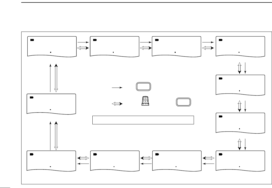
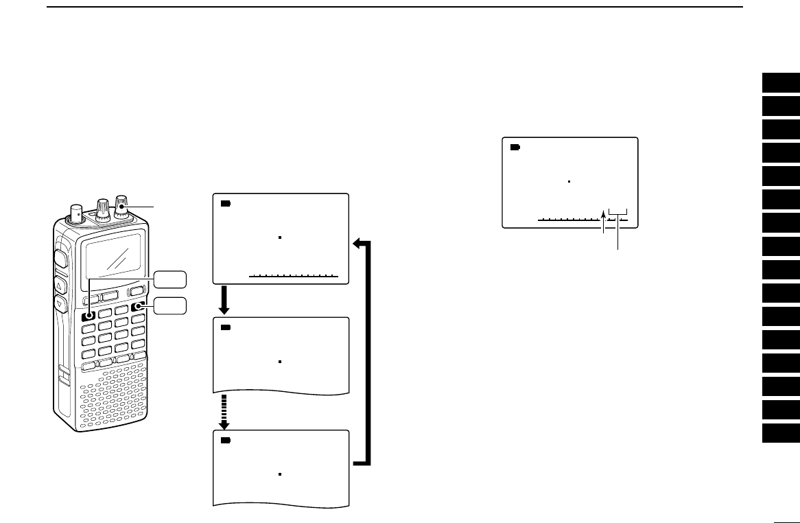
■Operating band selection
The receiver can receive the AM broadcast, HF bands,
50 MHz, FM broadcast, VHF air, 144 MHz, 300 MHz,
400 MHz, 800 MHz,* 1200 MHz or 2400 MHz.
➥Push [BAND] several times to select the desired frequency
band.
• When a memory mode is selected, push [VFO MHz] to select
VFO mode first, then push [BAND] to select the desired band.
➥While pushing and holding [BAND], rotating [R-DIAL] also
selects frequency band.
Available frequency bands are differ depending on version.
See the specification for details.
*Some frequency ranges are inhibited for the USA version
due to local regulation.
[R-DIAL]
BAND
√
MODE ANL
AFCTSQL
WFM
76 000
PSKIP
-DUP
√
µ
MODE ANL
AFCTSQL
FM
146100
PSKIP
-DUP
001
0
√
MODE ANL
AFCTSQL
WFM
2ch
PSKIP
-DUP
TV
√
MODE ANL
AFCTSQL
FM
1
PSKIP
-DUP
WX
“µ ” and memory channel
number appear.
• PreSet channel indication
• TV channel indication
• Weather channel indication
(USA version only)
• Memory mode indication
PreSet channel number appears.
“TV” indication appears.
“WX” indication appears.
13
3FREQUENCY AND CHANNEL SETTING
• Available frequency bands
BAND
BAND
AM broadcast band HF band 50 MHz band
800 MHz band 400 MHz band
FM broadcast band
VHF air band
144 MHz band
300 MHz band1200 MHz band
2400 MHz band
: Push
: Rotating while pushing
Initial frequencies shown are differ according to version.
AM
MODE AM
MODE FM
MODE WFM
MODE
AM
MODE
FM
MODE
FM
MODE
FM
MODE
FM
MODE
1620 5000 51 000 76 000
118000
146010
370000440000800000
FM
MODE
1295000
FM
MODE
2425000
14
3
FREQUENCY AND CHANNEL SETTING
3
■Setting a tuning step
The tuning step can be selected for each frequency band in-
dependently , however, the tuning steps, 8.33 kHz and 9 kHz,
are appeared when setting the tuning step for the VHF air
band and AM broadcast band, respectively. The following tun-
ing steps are available for the IC-R20.
• 0.01 kHz • 0.1 kHz • 1.0 kHz • 5.0 kHz • 6.25 kHz
• 8.33 kHz • 9.0 kHz • 10.0 kHz • 12.5 kHz • 15.0 kHz
• 20.0 kHz • 25.0 kHz • 30.0 kHz • 50.0 kHz • 100.0 kHz
DDTuning step selection
qPush [VFO MHz] to select VFO mode, if necessary.
wPush [BAND] to select the desired frequency band.
• Or, while pushing and holding [BAND], rotate the [R-DIAL] to se-
lect the desired frequency band.
ePush [9 TS] for 1 sec. to enter tuning step selecting condition.
rRotate [R-DIAL] to select the desired tuning step.
tPush [9 TS] to return to VFO mode.
■Setting a frequency
DDUsing the dial
qPush [VFO MHz] to select VFO mode, if necessary.
wSelect the desired frequency band with [BAND].
• Or, while pushing and holding [BAND], rotate the [R-DIAL] to se-
lect the desired frequency band.
eRotate [R-DIAL] to select the desired frequency.
• The frequency changes according to the preset tuning steps.
See the left section for setting the tuning step.
• Push [VFO MHz] for 1 sec. then rotate [R-DIAL] to change the
frequency in 1 MHz steps, or push for 1 sec. again then rotate
[R-DIAL] to change the frequency in 10 MHz steps. (Each push
for 1 sec. toggles 1 MHz or 10 MHz tuning steps.)
FM
MODE
14601000
FM
MODE
14601000
[R-DIAL] changes the frequen-
cy according to the selected
tuning step.
While pushing [
VFO MHz
], [R-
DIAL] changes the frequency in
1 MHz steps (default).
[R-DIAL]
BAND
VFO
MHz
SET TS:5.0kHz
√
MODE ANL
AFCTSQL
FM
146010
PSKIP
-DUP
5 kHz tuning step
[R-DIAL]
TS
9
BAND
VFO
MHz
15
3FREQUENCY AND CHANNEL SETTING
DDUsing the keypad
The frequency can be directly set via numeral
keys.
• When editting a frequency outside of the fre-
quency range, the previously displayed frequency
is automatically recalled after editting last digit.
qPush [VFO MHz] to select VFO mode, if
necessary.
wEnter the desired frequency via the keypad.
• Direct input can be set until 1 kHz digit, rotate
[R-DIAL] to set below 1 kHz frequency after
set tuning steps, if necessary. (See the previ-
ous page for setting the tuning step.)
123
4560
789
LOCK
AFC
DUALWATCH
VFO
MHz
Pushing [VFO MHz] omits the entry of 100 kHz and below, when you want to
edit to these digits “0.” Push [DUALWATCH] to cancel the entry.
AM
MODE
000010
AM
MODE
000010
AM
MODE
000 684
AM
MODE
000684
AM
MODE
000684
FM
MODE
1000
FM
MODE
12 000
FM
MODE
126000
FM
MODE
1260000
FM
MODE
1260000
FM
MODE
1260240
FM
MODE
1260 240
FM
MODE
1260240
FM
MODE
1260240
1
2
2
4
4
6
6
8
VFO
MHz
0
AFC
0
AFC
0
AFC
LOCK LOCK
• Editting to 0.684 MHz • Editting to 1260 MHz • Changing 100 kHz and
below.
Editting 1260.000 MHz
to 1260.240 MHz
16
3
FREQUENCY AND CHANNEL SETTING
1
2
3
4
5
6
7
8
9
10
11
12
13
14
15
16
■Receive mode selection
Receive modes are determined by the physical properties of
the radio signals. The receiver has 6 receive modes: FM,
WFM, AM, LSB, USB and CW modes. The mode selection is
stored independently in each band and memory channels.
Typically, AM mode is used for the AM broadcast stations
(0.495–1.620 MHz) and VHF air band (118–135.995 MHz),
and WFM is used for FM broadcast stations (76–107.9 MHz).
➥Push [MODE SCAN] several times to select the desired
receive mode.
■Lock function
To prevent accidental frequency changes and unnecessary
function access, use the lock function.
➥Push [• LOCK] for 1 sec. to turn the lock function ON and
OFF.
• “ ” appears while the lock function is activated.
•[SQL] and [YY]/[ZZ]can be used while the lock function is in use
with default setting. Either or both [SQL] and [YY]/[ZZ]keys are
also be locked in set mode. (p. 49)
√
MODE ANL
AFCTSQL
FM
146010
PSKIP
-DUP
DIAL.SEL SWEEP CENTER
T-SCAN SKIP M.N
TONE SET TS
ATT RF GAIN
IC Recorder
123
4560
789
BAND
DUALWATCH
MAIN/SUB
POWER
VFO
MHz MODE
SCAN MR
S.MW
SCOPE
LOCK
REC
AFC
“ ” appears while the
lock function is in use.
LOCK
DIAL.SEL SWEEP CENTER
T-SCAN SKIP M.N
TONE SET TS
ATT RF GAIN
IC Recorder
123
4560
789
BAND
DUALWATCH
MAIN/SUB
POWER
VFO
MHz MODE
SCAN MR
S.MW
SCOPE
LOCK
REC
AFC
MODE
SCAN
WFM
MODE
AM
MODE
FM
MODE
76 000
118000
146010
PSKIP
PSKIP
PSKIP
FM mode
AM mode
WFM mode
17
BASIC OPERATION
4
■Receiving
Make sure charged battery pack (BP-206) or brand new al-
kaline batteries are installed (p. 8).
qPush [POWER] for 1 sec. to turn power ON.
wRotate [L-DIAL] (or push [YY]or [ZZ]) to set the desired
audio level.
• The frequency display shows the volume level while setting. See
the section at right for details.
eSet the receiving frequency. (p. 14)
rSet the squelch level. (p. 18)
• While pushing [SQL], rotate [R-DIAL].
• The first click of [R-DIAL] indicates the current squelch level.
• “LEVEL 1” is loose squelch and “LEVEL 9” is tight squelch.
• “AUTO” indicates automatic level adjustment with a noise pulse
count system.
• Push and hold [SQL] to open the squelch manually.
tWhen a signal is received:
• Squelch opens and audio is emitted.
• The S-meter shows the relative signal strength level.
■Setting audio volume
The audio level can be adjusted through 39 levels.
➥Push and hold [SQL], rotate [L-DIAL] or p
ush [YY]or [ZZ]to
adjust the audio level.
• While using
[YY]/[ZZ]
, pushing and holding either key change the
audio level continuously.
• The display shows the volume level while setting.
√
MODE ANL
AFCTSQL
FM
VOL
146010
PSKIP
-DUP
√
VOL
√
VOL
[L-DIAL]
Minimum setting
(no audio)
Maximum setting
SQL
√
MODE ANL
AFCTSQL
FM
146010
P S KIP
-DUP
ATT
q [POWER]
e Set frequency
r Set squelch level
w Set audio level
e Select band
r Push for setting
the squelch
(Push to monitor)
18
4
BASIC OPERATION
4
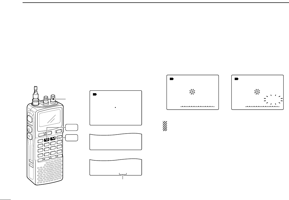
■Squelch level setting
The squelch circuit mutes the received audio signal depend-
ing on the signal strength. The receiver has 9 squelch levels,
a continuously open setting and an automatic squelch setting.
➥While pushing and holding [SQL], rotate [R-DIAL] to se-
lect the squelch level.
• “LEVEL 1” is loose squelch and “LEVEL 9” is tight squelch.
• “AUTO” indicates automatic level adjustment with a noise pulse
count system.
• “OPEN” indicates continuously open setting.
■Monitor function
This function is used to listen to weak signals without disturb-
ing the squelch setting or to open the squelch manually even
when mute functions such as the tone squelch are in use.
➥Push and hold [SQL] to monitor the operating frequency.
• The 1st segment of the S-meter blinks.
The [SQL] key can be set to ‘sticky’ operation in expanded
set mode. See page 54 for details.
√
MODE ANL
AFCTSQL
FM
146010
PSKIP
-DUP
The 1st segment blinks
SQL
SQUELCH:AUTO
√
MODE ANL
AFCTSQL
FM
146010
PSKIP
-DUP
SQUELCH:LEVEL9
√
MODE ANL
AFCTSQL
FM
146010
PSKIP
-DUP
Automatic squelch
Maximum level
[R-DIAL]
SQL
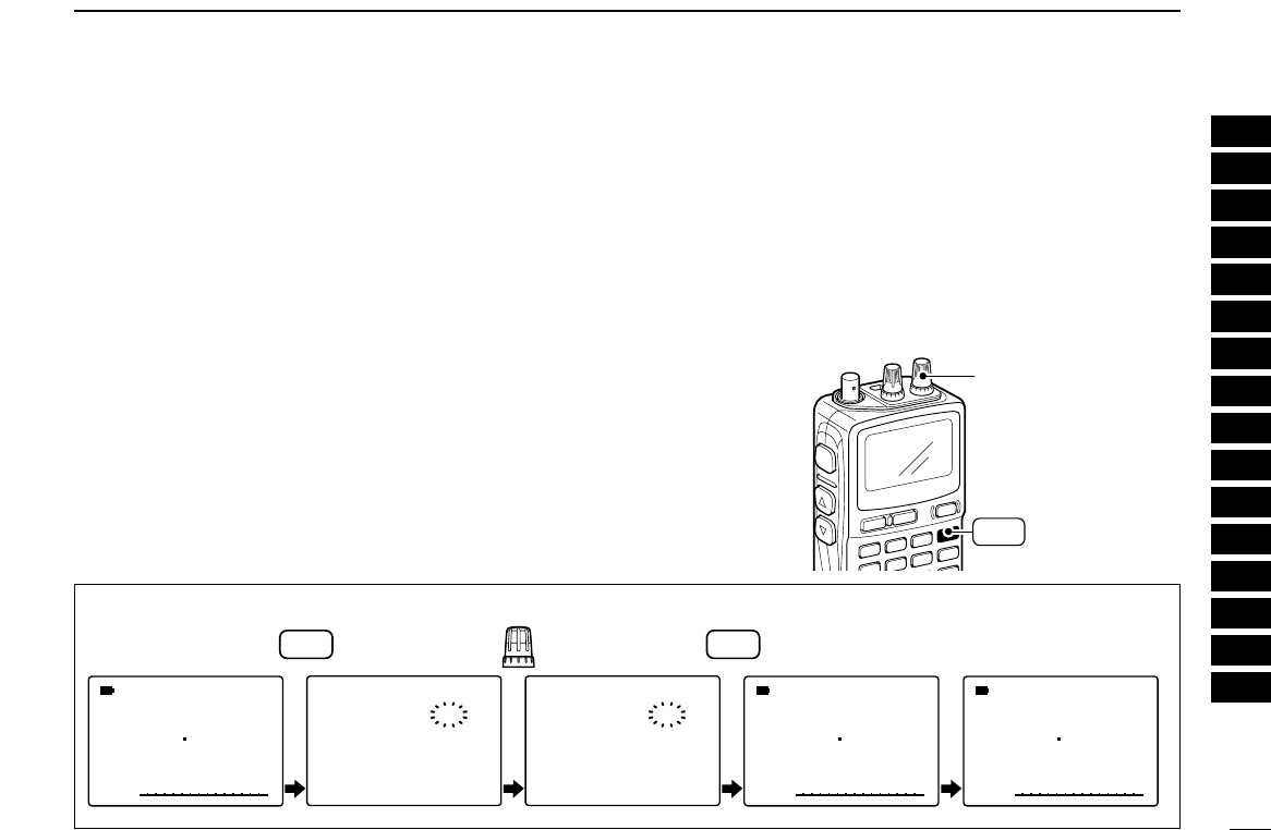
■Attenuator function
The attenuator prevents a desired signal from distorting when
very strong signals are near the desired frequency or when
very strong electric fields, such as from a broadcasting sta-
tion, are near your location.
➥
Push
[
ΩΩΩΩ
ATT]
for 1 sec. to toggle the attenuator function
ON and OFF.
• “ATT” appears when the attenuator function is in use.
■RF gain
The receiver gain can be reduced with the RF gain setting.
This may help to remove undesired weak signals while mon-
itoring strong signals. The RF gain may be useful for setting a
minimum level at which to hear signals for SSB/CW modes .
➥Push [
≈≈≈≈
RF GAIN]
for 1 sec. to enter the RF gain set-
ting condition, then rotate [R-DIAL] to select the desired
RF gain level.
• Normally this setting is used maximum level.
• Push [DUALWATCH] to exit the RF gain setting condition.
SET-RF-GAIN:MAX
√
MODE ANL
AFCTSQL
USB
14 120
PSKIP
-DUP
SET-RF-GAIN:5
√
MODE ANL
AFCTSQL
USB
14 120
PSKIP
-DUP
Maximum level
Setting level5
[R-DIAL]
RF GAIN
ATT
√
MODE ANL
AFCTSQL
FM
146010
PSKIP
-DUP
ATT
DIAL.SEL SWEEP CENTER
T-SCAN SKIP M.N
TONE SET TS
ATT RF GAIN
IC Recorder
123
4560
789
BAND
DUALWATCH
MAIN/SUB
POWER
VFO
MHz MODE
SCAN MR
S.MW
SCOPE
LOCK
REC
AFC
“AT T ” appears while the
attenuator functions is in
use.
19
4BASIC OPERATION
20
4
BASIC OPERATION
4
Duplex communication uses 2 different frequencies for trans-
mitting and receiving. Generally, duplex is used in communi-
cation through a repeater, some utility communications, etc.
During duplex operation, the transmit station frequency is
shifted from the receive station frequency by the offset fre-
quency. Repeater information (offset frequency and shift di-
rection) can be programmed into memory channels. (p. 26)
DDSetting
qSet the receive station frequency (repeater output frequency).
wPush [8 SET] for 1 sec. to enter set mode.
eRotate [R-DIAL] to select “SET EXPAND” item, then push
[8 SET].
rRotate [R-DIAL] to select “ON.”
tRotate [R-DIAL] to select “OFFSET FREQ,” then push
[8 SET].
yRotate [R-DIAL] to set the desired offset frequency within
0.00000–159.99999 MHz range, then push [8 SET].
• The tuning step, selected in VFO mode, is used for setting.
• Push [VFO MHz] for 1 sec. then rotate [R-DIAL] to change the
frequency in 1 MHz steps, or push for 1 sec. again then rotate
[R-DIAL] to change the frequency in 10 MHz steps. (Each push
for 1 sec. toggles 1 MHz or 10 MHz tuning steps.)
uRotate [R-DIAL] to select “DUPLEX.”
iRotate [R-DIAL] to select “–DUP” or “+DUP.”
oPush [DUALWATCH] to exit set mode.
!0Push and hold [SQL] to monitor the transmit station fre-
quency (repeater input frequency) directly.
DUPLEX
--DUP
>OFF
-+DUP
----------------
OFFSET-FREQ
----0.000.00
----------------
[R-DIAL]
DUALWATCH
SET
8
SET TS:5.0kHz
√
MODE ANL
AFCTSQL
FM
146010
P S KIP
-DUP
***-SET-MODE-***
>SET-EXPAND
-FM-ANTENNA
-AM-ANTENNA
-AF-FILTER
-ANL
-NOISE-BLANKER
----------------
■Duplex operation
USING
EXPANDED SET MODE
21
4BASIC OPERATION
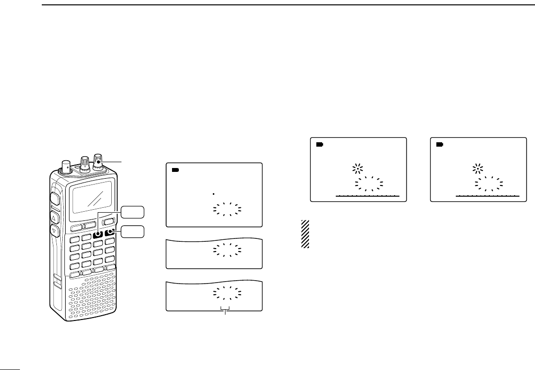
■AFC function
The AFC (Automatic Frequency Control) function tunes the
displayed frequency automatically when an off-center fre-
quency is received. It activated in FM/WFM modes only with
single band operation.
➥
Push
[0 AFC]
to toggle the AFC function ON and OFF.
• “AFC” appears when the AFC function is in use.
NOTE: The AFC function is not available during duwal-
watch operation.
■NB/ANL function
The NB (noise blanker) function removes pulse-type noise
when USB, LSB or CW mode is selected. The ANL (Auto-
matic Noise Limitter) function reduces noise components
when AM mode is selected.
See page 22 for setting details
NOTE: No display indication appears during dualwatch
function, but both functions are activate while in specific
modes.
ATT
√
MODE ANL
AFCTSQL
FM
1260000
P S KIP
-DUP
ATT
√
MODE ANL
AFC
TSQL
FM
1260000
PSKIP
-DUP
DIAL.SEL SWEEP CENTER
T-SCAN SKIP M.N
TONE SET TS
ATT RF GAIN
IC Recorder
123
4560
789
BAND
DUALWATCH
MAIN/SUB
POWER
VFO
MHz MODE
SCAN MR
S.MW
SCOPE
LOCK
REC
AFC
“AFC” appears while the
AFC function is in use.
0
AFC
“ ” “ ”
or
an off-frequency is received.
appears when
22
4
BASIC OPERATION
1
2
3
4
5
6
7
8
9
10
11
12
13
14
15
16
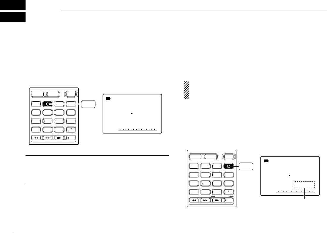
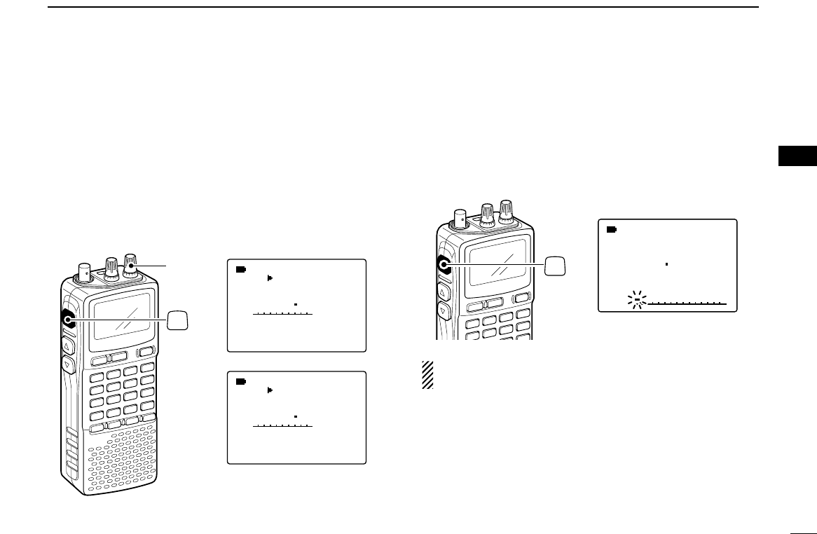
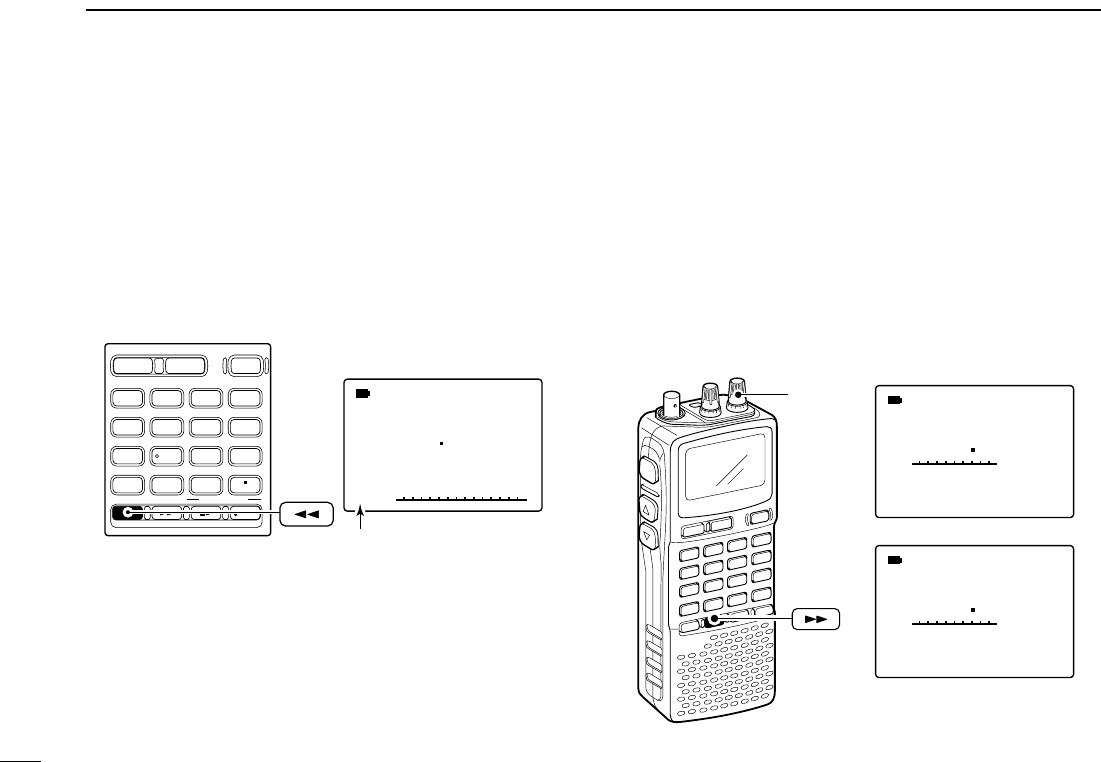
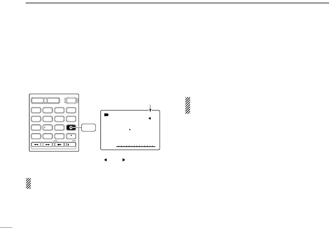
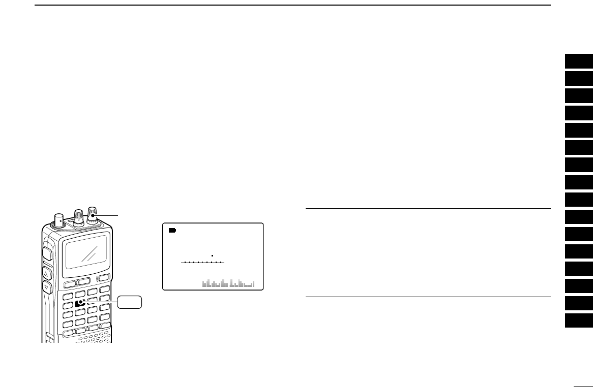
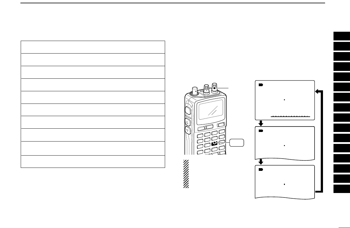
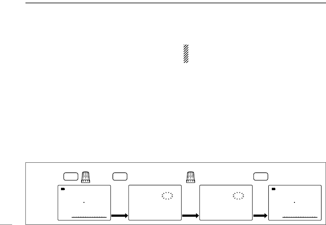
■Band scope
The band scope function allows you to visually check a spec-
ified frequency range. Sweep range can be selected from ±14
kHz through ±1400 kHz.
qSet the desired frequency as band scope center frequency.
wWhile pushing and holding [2 SWEEP], rotate [R-DIAL] to
select the sweep steps, if desired.
• Available steps are 1, 5, 6.25, 8.33, 9, 10, 12.5, 15, 20, 25, 30,
50 and 100 kHz.
• Each pushing [SWEEP] changes the sweep step and starts sin-
gle sweeping at each times.
ePush [SCOPE] momentarily to start single sweeping or
push for 1 sec. to start continuous sweeping.
• Signal conditions (strengths) appear starting from the center of
the range.
rRotate [R-DIAL] to set the highlighted cursor to the de-
sired waveform and set the frequency of the signal.
• Push [3 CENTER] for 1 sec. to return to original sweep center
frequency.
tPush [DUALWATCH] to cancel sweeping and returns to
normal condition.
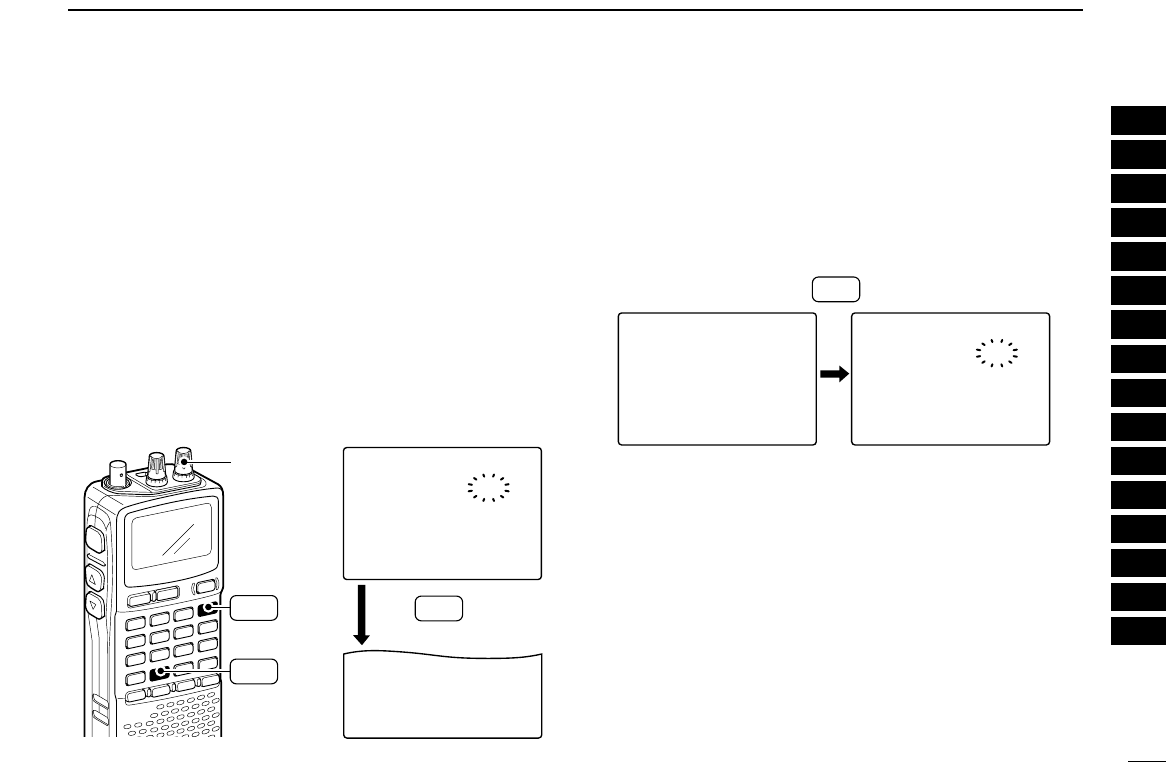
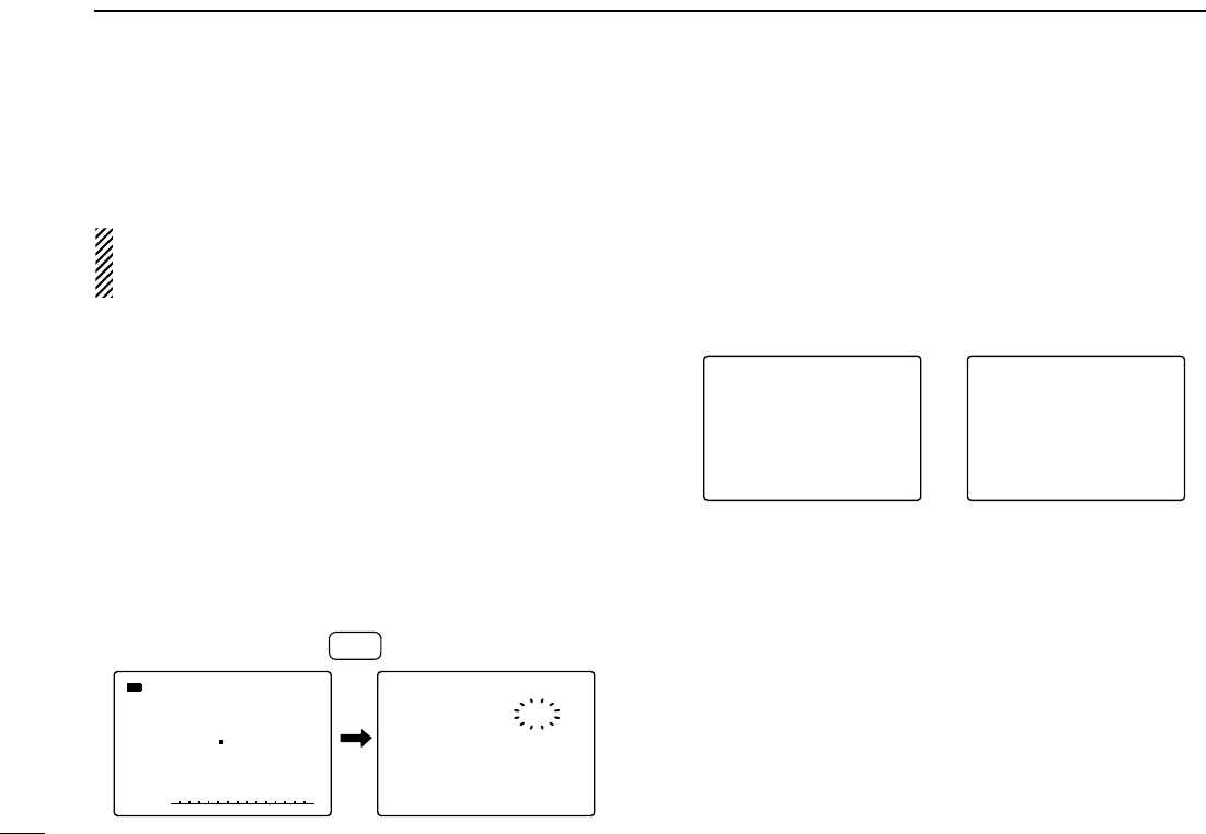
✔
CONVENIENT!
The scope function can also be started with the following op-
eration for easy setting.
qSet the desired frequency as band scope center frequency.
wPush [SWEEP] for 1 sec. to start single sweeping.
• Each pushing [SWEEP] changes the sweep step and starts sin-
gle sweeping at each times.
√
MODE
ANL
AFCTSQL
FM
145780
PSKIP
SWEEP
10k
-DUP
[R-DIAL]
SWEEP
2
23
4BASIC OPERATION
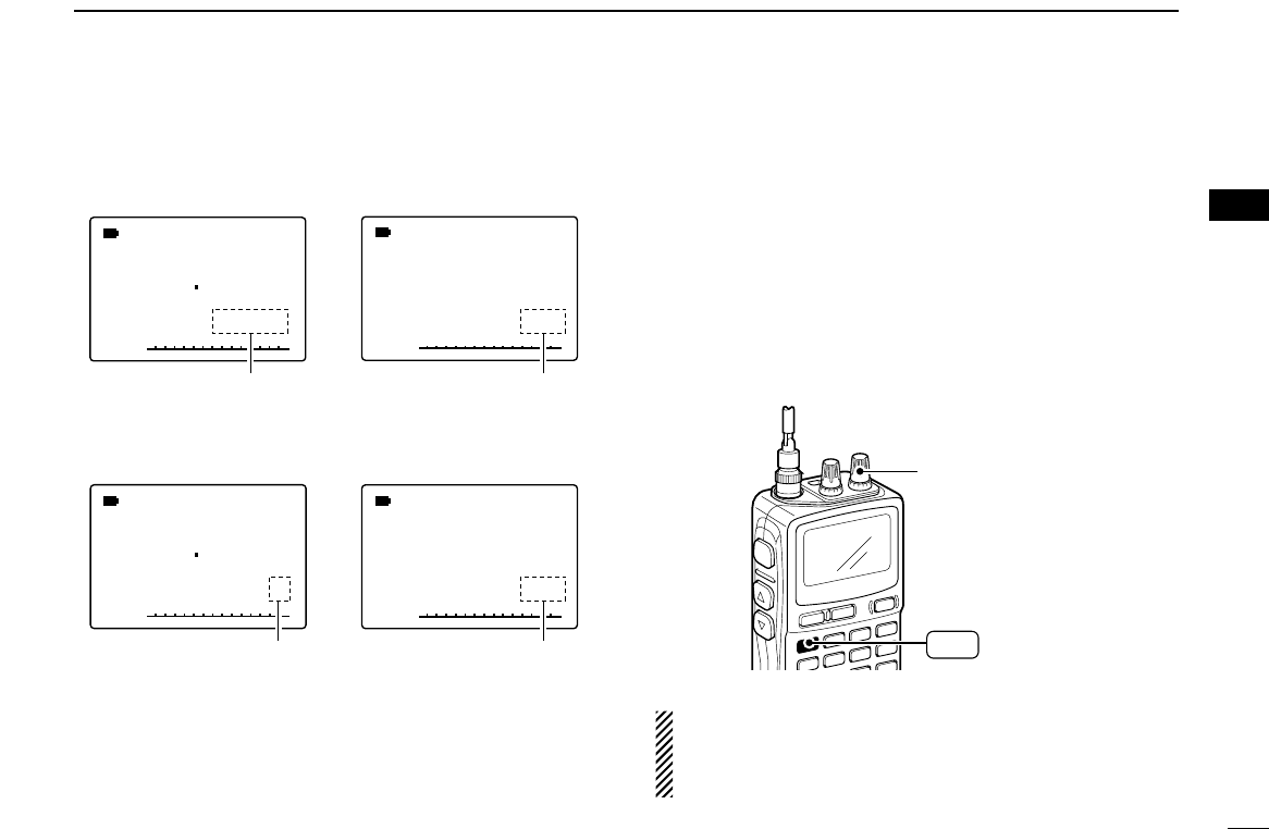
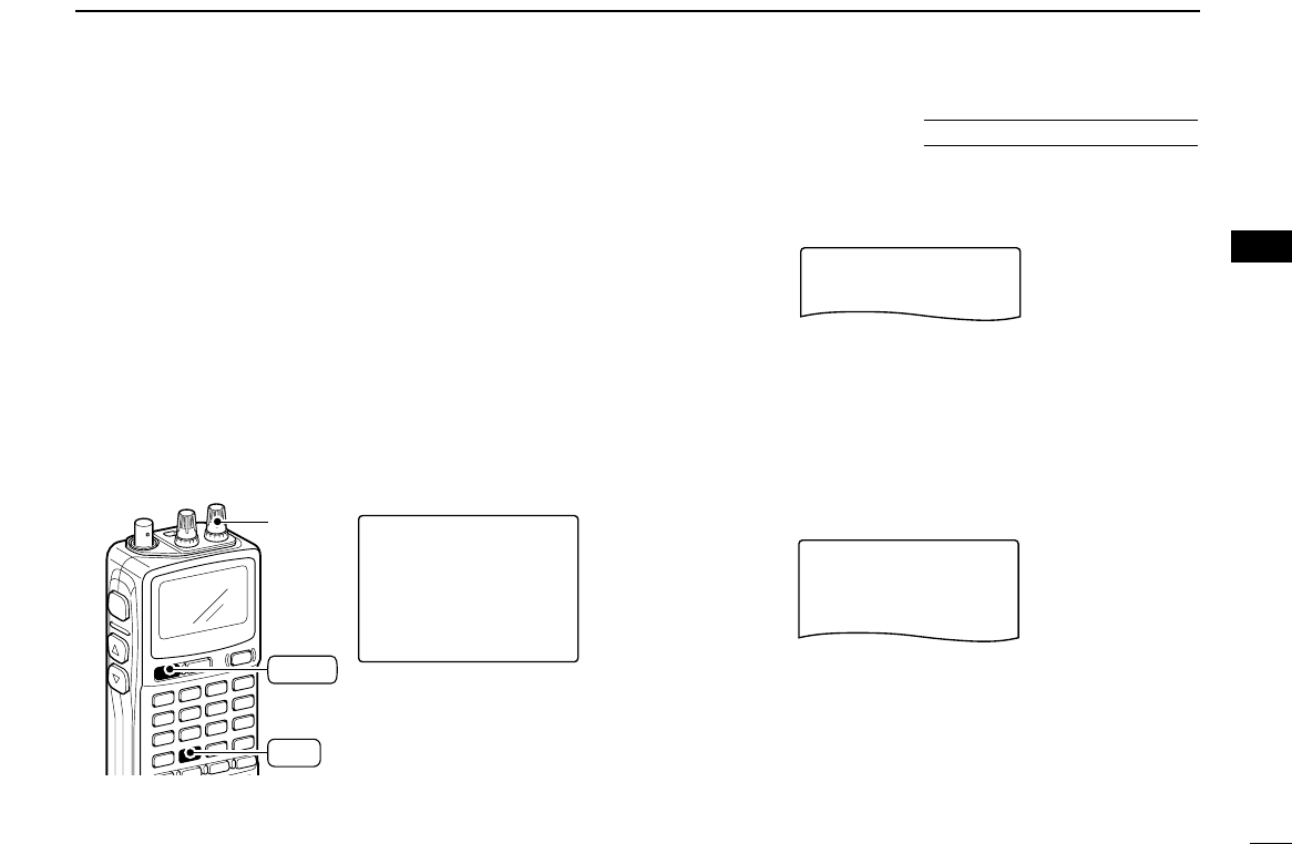
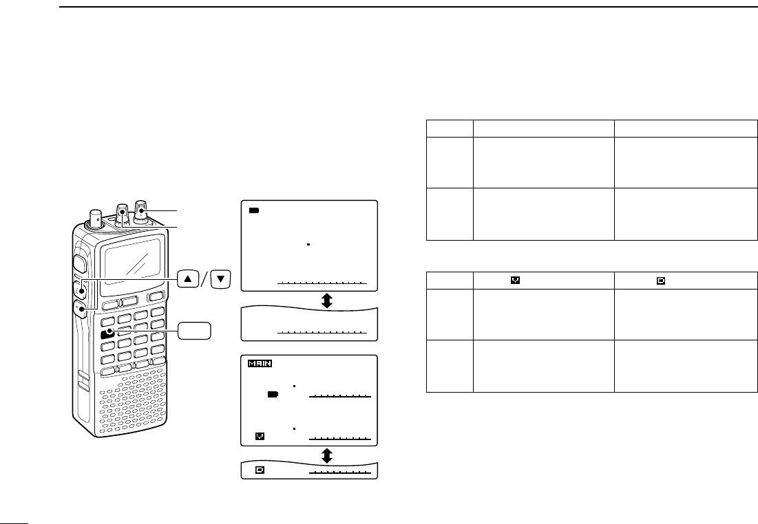
■[DIAL] function assignment
The frequency control dial can be traded with an audio volume
control dial or [YY]/[ZZ]keys to suit your preference.
➥
Push [1 DIAL] for 1 sec. to toggle the dial function from tun-
ing dial and audio volume.
•“∂” appears when
[YY]/[ZZ]
function as an tuning dial.
•Single band operation
•Dualwatch operation
√
MODE ANL
AFCTSQL
FM
146560
PSKIP
-DUP
∂
145250
438000
AFC -DUP
-DUP
FM
TSQL
TSQL
PS
PS
PRIO
PRIO
FM
000
000
00
00
FM
[R-DIAL]
[L-DIAL]
DIAL.SEL
1
“ √” indication “ ∂” indication
Frequency, Memory channel,
Audio volume
[R-DIAL] Squelch level, Scanning
direction, Set mode item
and condition set
Audio volume set
Frequency, Memory channel,
[L-DIAL] Squelch level, Scanning
[Y]/[Z] direction, Set mode item
and condition set
“ ” indication “ ” indication
Frequency, Memory channel,
Audio volume
[R-DIAL] Squelch level, Scanning
[L-DIAL] direction, Set mode item
and condition set
Audio volume set
Frequency, Memory channel,
[Y]/[Z]Squelch level, Scanning
direction, Set mode item
and condition set
24
5
DUALWATCH OPERATION
1
2
3
4
5
6
7
8
9
10
11
12
13
14
15
16
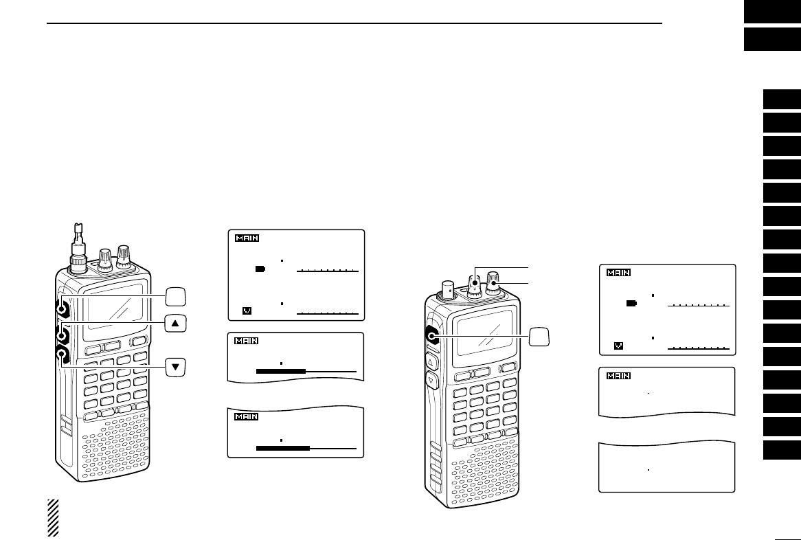
■Setting audio volume
qPush [DUALWATCH] for 1 sec. to enter the dualwatch op-
eration, if necessary
wPush and hold [SQL], p
ush [YY]or [ZZ]to adjust the audio
level for the main band.
• Pushing and holding either key change the audio level continu-
ously.
• The display shows the volume level while setting.
While pushing either
[YY]or [ZZ]
, rotate [L-DIAL] for upper
band’s volume adjustment, or [R-DIAL] for lower band’s
volume adjustment.
■Squelch level setting
qPush [DUALWATCH] for 1 sec. to enter the dualwatch op-
eration, if necessary
wWhile pushing and holding [SQL], rotate [L-DIAL] for
upper band’ squelch adjustment, or rotate [R-DIAL] for
lower band’s squelch adjustment.
• “LEVEL 1” is loose squelch and “LEVEL 9” is tight squelch.
• “AUTO” indicates automatic level adjustment with a noise pulse
count system.
• “OPEN” indicates continuously open setting.
145 000
433 000
AFC -DUP
-DUP
FM
TSQL
TSQL
PS
PS
P RIO
P RIO
LSB
000
000
00
00
145250
438000
AFC -DUP
-DUP
FM
TSQL
TSQL
PS
PS
PRIO
PRIO
FM
000
000
00
00
PS
PS
PS
SQUELCH:LEVEL9
438
.
000
SQUELCH:AUTO
PS
145
.
250
[R-DIAL]
[L-DIAL]
SQL
Upper band setting
Lower band setting
145250
438000
AFC -DUP
-DUP
FM
VOL
VOL
TSQL
TSQL
PS
PS
PRIO
PRIO
FM
000
000
00
00
145250
438000
PS
PS
000
000
Upper band setting
Lower band setting
SQL
25
5DUALWATCH OPERATION
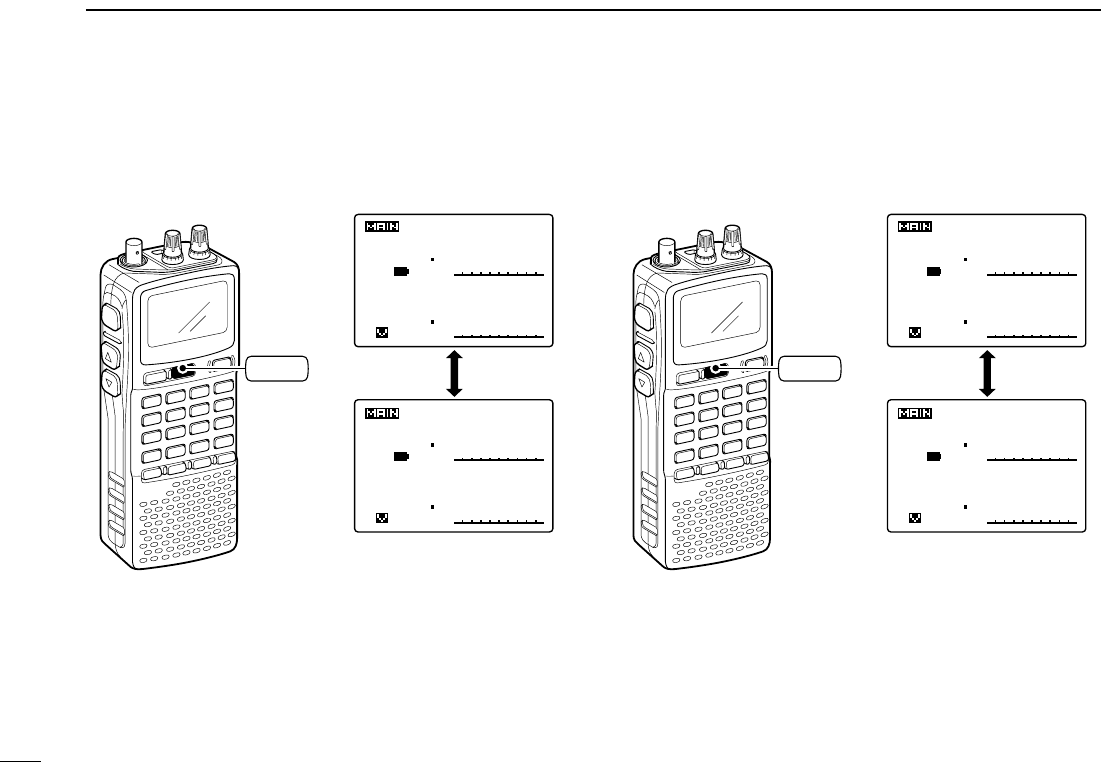
■Main band selection
➥Push [MAIN/SUB] momentarily to select the upper band
or lower band as main band (operating band) alternately.
■Band exchange
➥Push [MAIN/SUB] for 1 sec to exchange the upper band’s
frequency and lower band’s frequency.
145 000
433 000
AFC -DUP
-DUP
FM
TSQL
TSQL
PS
PS
P RIO
P RIO
LSB
000
000
00
00
145250
438000
AFC -DUP
-DUP
FM
TSQL
TSQL
PS
PS
PRIO
PRIO
FM
000
000
00
00
438000
145250
-DUP
-DUP
FM
TSQL
TSQL
PS
PS
PRIO
PRIO
FM
000
000
00
00
PS
PS
MAIN/SUB
145 000
433 000
AFC -DUP
-DUP
FM
TSQL
TSQL
PS
PS
P RIO
P RIO
LSB
000
000
00
00
145250
438000
AFC -DUP
-DUP
FM
TSQL
TSQL
PS
PS
PRIO
PRIO
FM
000
000
00
00
438000
145250
-DUP
-DUP
FM
TSQL
TSQL
PS
PS
PRIO
PRIO
FM
000
000
00
00
PS
PS
MAIN/SUB
26
6
MEMORY CHANNELS
■General description
The receiver has 1050 memory channels including 50 scan
edge memory channels (25 pairs) for storage of often-used
frequencies. And a total of 26 memory banks, A to Z are avail-
able for usage by group, etc. Up to 100 channels can be as-
signed into a bank.
DDMemory channel contents
The following information can be programmed into memory
channels:
• Operating frequency (p. 14)
• Receive mode (p. 16)
• Duplex direction (+DUP or –DUP) with an offset fre-
quency (p. 20)
• Tone squelch or DTCS squelch ON/OFF (p. 45)
• Tone squelch frequency or DTCS code with polarity
(p. 46)
• Scan skip information* (p. 39).
■
Memory channel programming
qPush [VFO MHz] to select VFO mode.
wSet the desired frequency:
➥Select the desired band with [BAND].
➥Set the desired frequency with [R-DIAL].
➥Or set the desired frequency with [KEYPAD].
➥Set other data (e.g. offset frequency, duplex direction, tone
squelch, etc.), if desired.
ePush [MR S.MW] for 1 sec. to select the select memory
write condition.
• 1 short and 1 long beep sound.
•“µ” indicator blinks.
rRotate [R-DIAL] to select the desired channel.
• Scan edge channel, 00A/B to 24A/B can also be selected.
tPush [MR S.MW] for 1 sec.
• 3 beeps sound
• Memory channel number automatically increases when contin-
uing to push [MR S.MW] after programming.
[EXAMPLE]: Programming 145.870 MHz into memory channel 20 (blank channel).
√
µ
MODE
ANL
AFCTSQLTSQL
FM
FM
145870
PSKIP
-DUP-DUP
001
√
µ
MODE
ANL
AFCTSQLTSQL
FM
145870
PSKIP
-DUP-DUP
020
√
µ
MODE
ANL
AFCTSQLTSQL
FM
145870
PSKIP
-DUP-DUP
020
>CLEARCLEAR
-SKIPSKIP-:OFF:OFF
-MNAME:MNAME:
-BNAME:-BNAME:
-BANKBANK-:----:----
001001
µ
.
146
.
010
FM
>CLEARCLEAR
-SKIPSKIP-:OFF:OFF
-MNAME:MNAME:
-BNAME:-BNAME:
-BANKBANK-:----:----
020020
µ
.
--------------------------------
Push for 1 sec. Rotate
MR
S.MW
Push for 1 sec.
MR
S.MW
1
2
3
4
5
6
7
8
9
10
11
12
13
14
15
16
27
6MEMORY CHANNELS
■Memory bank setting
The IC-R20 has a total of 26 banks (A to Z). Regular memory
channels, 000 to 999, are assigned into the desired bank for
easy memory management.
qPush [MR S.MW] for 1 sec. to select the select memory
write condition.
• 1 short and 1 long beep sound.
•“µ” indicator blinks.
wRotate [R-DIAL] to select the desired memory channel.
eWhile pushing [8 SET], rotate [R-DIAL] to select “BANK”
item.
• “BANK” item can also be selected by pushing [8 SET] several
times.
• Bank group and channel number is displayed if the selected
memory channel has already been assigned into a bank, the
previous.
rWhile pushing [BAND], rotate [R-DIAL] to select the de-
sired bank group from “A” to “Z.”
• The bank group can also be selected by pushing [BAND] sev-
eral times.
tAfter releasing [BAND], rotate [R-DIAL] to select the bank
channel number from “00” to “99.”
• Vacant bank channel numbers are only be displayed.
yPush [MR S.MW] for 1 sec. to set the channel into the
bank.
• Return to the previous indication.
-BNAME:
FM
>BANK-:A-00
012
µ
.
146
.
010
Bank channel is selected with [R-DIAL]
-BNAME:
FM
>BANK-:A-00
012
µ
.
146
.
010
Bank group is selected with
BAND
FM
>CLEAR
-SKIP-:OFF
-MNAME:
-BNAME:
-BANK-:----
012
µ
.
146
.
010
FM
>BANK-:----
012
µ
.
146
.
010
is pushedAfter
[R-DIAL]
SET
8
SET
8
MR
S.MW
BAND
SET TS:5.0kHz
√
MODE ANL
AFCTSQL
FM
146010
P S KIP
-DUP
28
6
MEMORY CHANNELS
■Memory bank selection
qPush [MR S.MW] to select memory mode.
wWhile pushing [BAND], rotate [R-DIAL] to select the de-
sired bank (A to Z).
• The bank can also be selected by pushing [BAND] several
times.
• The only programmed banks are displayed.
eRotate [R-DIAL] to select the bank channel.
• The only programmed channels are displayed.
rTo return to regular memory
condition, rotate [R-DIAL] while
pushing
[BAND], or push [BAND] several times.
ATT
√
µ
MODE ANL
AFCTSQL
FM
145870
PSKIP
-DUP
A99
Bank initial
Bank chanel number
ATT
√
µ
MODE ANL
AFCTSQL
FM
145870
PSKIP
-DUP
001
√
µ
MODE ANL
AFCTSQL
AM
118000
P S KIP
-DUP
A12
√
µ
MODE ANL
AFCTSQL
FM
438720
P S KIP
-DUP
Y01
Rotate [R-DIAL] while
pushing [BAND]
Appears only the
programmed bank.
[R-DIAL]
MR
S.MW
BAND
SET TS:5.0kHz
√
MODE ANL
AFCTSQL
FM
146010
P S KIP
-DUP
1
2
3
4
5
6
7
8
9
10
11
12
13
14
15
16
29
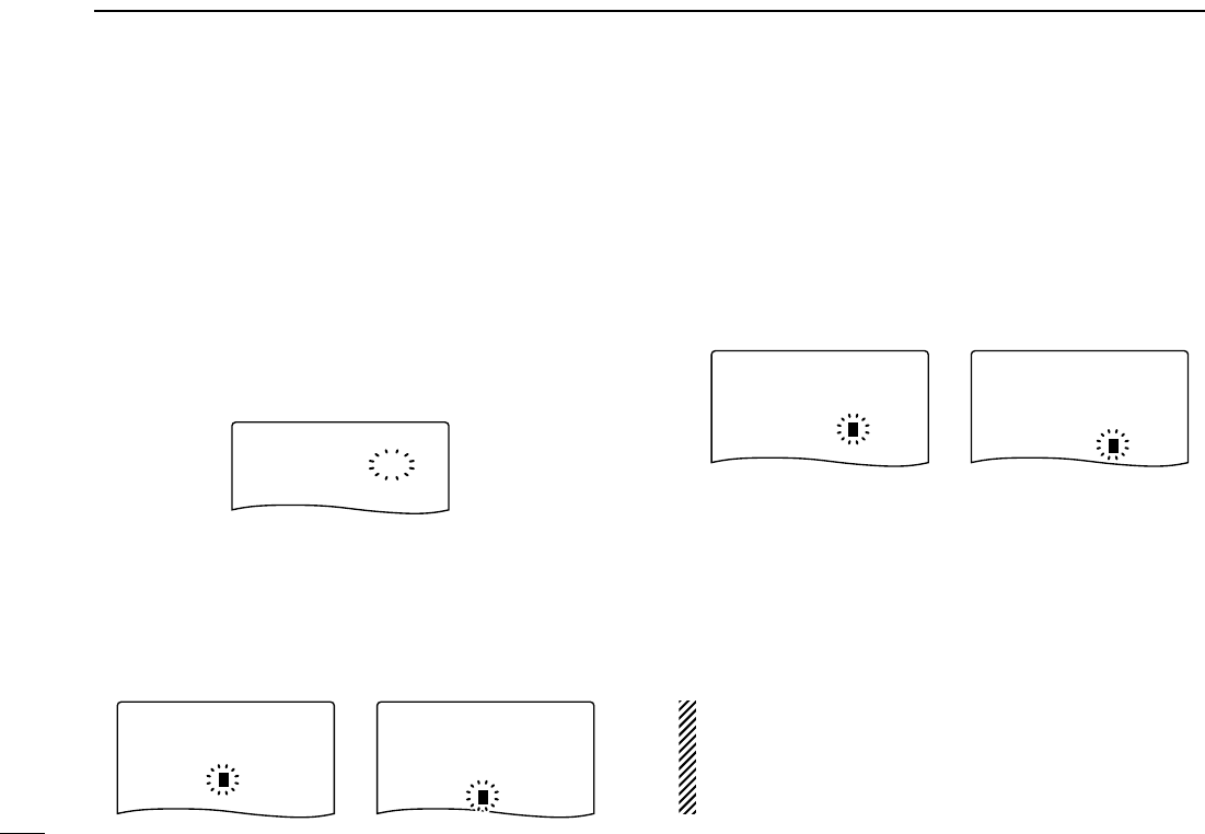
6MEMORY CHANNELS
■Programming memory/bank name
Each memory channel can be programmed with an alphanu-
meric channel name for easy recognition and can be indicated
independently by channel. Names can be a maximum of 8
characters.
qPush [MR S.MW] to select memory mode.
wRotate [R-DIAL] to select the desired memory channel.
ePush [MR S.MW] for 1 sec. to select the select memory
write condition.
• 1 short and 1 long beep sound.
•“µ” indicator blinks.
rWhile pushing [8 SET], rotate [R-DIAL] to select “BNAME”
or “MNAME” when programming the memory name or the
bank name, respectively.
• The item can also be selected by pushing [8 SET] several times.
• After selecting the memory or bank name programming condi-
tion, an under bar blinks for the first digit.
tRotate [R-DIAL] to select the desired character.
• The selected character blinks.
• While pushing [6 M.N], rotate [R-DIAL] to select the character
group.
yWhile pushing [BAND], rotate [R-DIAL] to move the cur-
sor to left or right.
• Push [BAND] to move the cursor to right.
uRepeat steps tand yuntil the desired 8-character chan-
nel names are displayed.
iPush [MR S.MW] for 1 sec. to program the name and exit
the channel name programming condition.
• 3 beeps sound.
•Available characters
A to Z, 0 to 9, (, ), ✱, +, –, ,, /, |, = and space.
NOTE: One bank name can only be programmed into
each bank. Therefore, the previously programmed bank
name will be displayed when bank name indication is se-
lected. And also, the programmed bank name is assigned
for the other bank channels automatically.
FM
-MNAME:
-BANK-:C-11
012
µ
.
145
.
700
FM
>MNAME:Ric
>BNAME:>BNAME:GRO
-BANK-:C-11
012
µ
.
145
.
700
Bank name Memory name
FM
-MNAME:
>BNAME:
-BANK-:C-11
012
µ
.
145
.
700
FM
>MNAME:
>BNAME:
-BANK-:C-11
012
µ
.
145
.
700
Memory name selectionBank name selection
FM
>BANK-:C-11
012
µ
.
145
.
700
30
6
MEMORY CHANNELS
DDAvailable characters ■Selecting memory/bank name
indication
During memory mode operation, one of the programmed
memory name or bank name can be displayed below the fre-
quency indication.
qPush [MR S.MW] to select memory mode.
• Push [BAND] several times to select the desired bank group.
wWhile pushing [6 M.N], rotate [R-DIAL] to select display in-
dication type from bank name or memory name.
ATT
B:GROUP1
√
µ
MODE ANL
AFCTSQL
FM
145700
PSKIP
-DUP
012
M:Ricky
√
µ
MODE ANL
AFCTSQL
FM
145700
PSKIP
-DUP
012
B:GROUP1
√
µ
MODE ANL
AFCTSQL
FM
145700
PSKIP
-DUP
012
When no memory or bank
name is programmed with
the selected memory chan-
nel, no indication is dis-
played.
M.N
6
[R-DIAL]
1
2
3
4
5
6
7
8
9
10
11
12
13
14
15
16
A B C D E F G H I J K L M N O P
Q R S T U V W X Y Z
a b c d e f g h i j k l m n o p
q r s t u v w x y z
0 1 2 3 4 5 6 7 8 9
‰ Ò ¨ Î ! " # $ % & ' ( ) * + ,
- . / : ; < = > ? @ [ \ ] ^ _ {
| } ~
0 1 2 4 3
(space)
31
6MEMORY CHANNELS
■
Copying memory contents
This function transfers a memory channel’s contents to VFO
(or another memory channel). This is useful when searching
for signals around a memory channel frequency and for re-
calling the offset frequency, subaudible tone frequency etc.
DMemory➪VFO
qSelect the memory channel to be copied.
➥Push [MR S.MW] to select memory mode, then rotate
[R-DIAL] to select the desired memory channel.
• Select the bank channel with [BAND] and [R-DIAL], if desired.
wPush [MR S.MW] for 1 sec. to select the select memory
write condition.
• 1 short and 1 long beep sound.
•“µ” indicator blinks.
ePush [VFO MHz] to select “VFO.”
• Rotate [R-DIAL] can also select “VFO.”
rPush [MR S.MW] for 1 sec. to write the selected channel
contents to VFO mode.
• Returns to VFO mode automatically.
Pushing [MR S.MW] for 2 sec. at the step w, can also be
copied the memory contents to VFO. In this case, the
steps eand rare not necessary.
DMemory➪memory
qSelect the memory channel to be copied.
➥
Push
[MR S.MW]
to select memory mode, then rotate [R-
DIAL] to select the desired memory channel.
wPush [MR S.MW] for 1 sec. to select the select memory
write condition.
• 1 short and 1 long beep sound.
•“µ” indicator blinks.
• Do not hold [MR S.MW] for more than 1 sec. otherwise the
memory contents will be copied to VFO.
eRotate [R-DIAL] to select the target memory channel.
rPush [MR S.MW] for 1 sec. again to copy.
[EXAMPLE]: Copying channel 20 to 51.
√
µ
MODE
ANL
AFCTSQLTSQL
FM
FMFM
145870
P S KIP
-DUP-DUP TSQLTSQL
-DUP-DUP
020
√
µ
MODE
ANL
AFCTSQLTSQL
FM
145870
PSKIP
-DUP-DUP
051
>CLEARCLEAR
-SKIPSKIP-:OFF:OFF
-MNAME:MNAME:
-BNAME:-BNAME:
-BANKBANK-:----:----
020020
µ
.
145
.
870
FM
>CLEARCLEAR
-SKIPSKIP-:OFF:OFF
-MNAME:MNAME:
-BNAME:-BNAME:
-BANKBANK-:----:----
051051
µ
.
--------------------------------
Select memory
channel Push for 1 sec. Rotate
MR
S.MW
MR
S.MW
Push for 1 sec.
MR
S.MW
32
6
MEMORY CHANNELS
■Memory clearing
Contents of programmed memories can be cleared (blanked),
if desired.
qPush [MR S.MW] for 1 sec. to select the select memory
write condition.
• 1 short and 1 long beeps sound.
•“µ” indicator blinks.
• Do not hold [MR S.MW] for more than 2 sec. otherwise the
memory contents will be copied to VFO.
wRotate [R-DIAL] to select the desired memory channel to
be cleared.
eWhile pushing [8 SET], rotate [R-DIAL] to select “CLEAR.”
• “CLEAR” item can also be selected by pushing [8 SET] several
times.
rPush [MR S.MW] for 1 sec. to clear the contents.
• 3 beeps sound.
• The cleared channel changes to blank channel
• Return to the select memory write condition.— “µ” indicator
blinks. Push [DUALWATCH] to exit the select memory write con-
dition, then push [VFO MHz] to return to VFO mode.
☞NOTE: Be careful!— the contents of cleared memories
CANNOT be recalled even in bank channel opera-
tion.
FM
>CLEAR
-SKIP-:OFF
-MNAME:
-BNAME:
-BANK-:----
028
µ
.
144
.
010
FM
>CLEAR
-SKIP-:OFF
-MNAME:
-BNAME:
-BANK-:----
028
µ
.
144
.
010
Push for 1 sec.
MR
S.MW
FM
>CLEAR
-SKIP-:OFF
-MNAME:
-BNAME:
-BANK-:----
028
µ
.
144
.
010
>CLEAR
-SKIP-:OFF
-MNAME:
-BNAME:
-BANK-:----
FM
>BANK-:----
028
µ
.
144
.
010
is pushed
several times.
After
[R-DIAL]
SET
8
SET
8
MR
S.MW
SET TS:5.0kHz
√
MODE ANL
AFCTSQL
FM
146010
P S KIP
-DUP
1
2
3
4
5
6
7
8
9
10
11
12
13
14
15
16
33
6MEMORY CHANNELS
■Erasing/transferring bank contents
The bank contents of programmed memory channels can be
cleared or reassigned to another memory bank.
INFORMATION: Even if the memory bank contents are
cleared, the memory channel contents still remain pro-
grammed.
qSelect the desired bank contents to be transferred or
erased from the bank.
➥Push [MR S.MW] to select memory mode.
➥While pushing [BAND], rotate [R-DIAL] to select the
desired memory bank group.
➥Rotate [R-DIAL] to select the bank channel.
wPush [MR S.MW] for 1 sec. to enter the select memory
write condition.
• 1 short and 1 long beeps sound.
• Displays the original memory channel number automatically and
“µ” indicator blinks.
• Do not hold [MR S.MW] for more than 2 sec., otherwise the
memory contents will be copied to VFO.
ePush [8 SET] once to select “BANK” item.
• While pushing [8 SET] then rotate [R-DIAL] also selectable
“BANK” item.
rWhile pushing [BAND], rotate [R-DIAL] to select the de-
sired bank group to be transfer.
• Select “– – – –” indication when erasing the contents from the
bank.
tRotate [R-DIAL] to select the desired bank channel.
yPush [MR S.MW] for 1 sec.
FM
>CLEAR
-SKIP-:OFF
-MNAME:
-BNAME:
>BANK-:----
028
µ
.
145
.
700
FM
>CLEAR
-SKIP-:OFF
-MNAME:
-BNAME:
>BANK-:R-00
028
µ
.
145
.
700
When transferring When erasing
ATT
B:GROUP1
√
µ
MODE ANL
AFCTSQL
FM
145700
PSKIP
-DUP
A93
FM
>CLEAR
-SKIP-:OFF
-MNAME:
-BNAME:OSAKA
-BANK-:A-93
642
µ
.
145
.
700
Push for 1 sec.
MR
S.MW

34
7
SCAN OPERATION
1
2
3
4
5
6
7
8
9
10
11
12
13
14
15
16
■Scan types
Scanning searches for signals automatically and makes it
easier to locate new stations for contact or listening purposes.
There are 7 scan types and 4 resume conditions to suit your
operating needs.
FULL SCAN (p. 35) Repeatedly scans all frequen-
cies over the entire band.
Some frequency ranges are
not scanned according to the
frequency coverage of the re-
ceiver’s version.
150
kHz
3304.980
MHz
Scan
Jump
SELECTED BAND SCAN
(p. 35)
Repeatedly scans all frequen-
cies over the entire selected
band.
Band
edge
Band
edge
Scan
Jump
ALL/SELECTED BANK
SCAN (p. 37)
Repeatedly scans all bank
channels or selected bank
channels. The skip scan is
also available.
SKIP
SKIP
A99 A03
A00 A01 A02
A04
A98
A05
FREQUENCY/MEMORY
SKIP FUNCTION (p. 39)
Skips unwanted frequencies
or channels that inconve-
niently stop scanning. This
function can be turned ON
and OFF by pushing and
holding [5 SKIP] in either
VFO or memory mode.
Band
edge
Band
edge
Scan
SKIP SKIP
Jump
PROGRAMMED SCAN
(p. 37)
Repeatedly scans between
two user-programmed fre-
quencies. Used for checking
for frequencies within a speci-
fied range such as repeater
output frequencies, etc.
Band
edge xxA xxB
Band
edge
Scan edges
Scan
Jump
MEMORY (SKIP) SCAN
(p. 37)
Repeatedly scans memory
channels except those set as
skip channel. Skip channels
can be turned ON and OFF
by pushing and holding [5
SKIP] in memory mode.
SKIP
SKIP
M 0 M 4
M 1 M 2 M 3
M 5
M 199
M 6
35
7SCAN OPERATION
■Full/band/programmed scan
qSelect VFO mode with [VFO MHz].
• Select the desired frequency band with [BAND], if desired.
wSet the squelch level.
eWhile pushing and holding [MODE SCAN], rotate [R-DIAL]
to select the desired scanning type.
• “ALL” for full scan; “BAND” for band scan, “PROG-xx” for pro-
grammed scan (xx= 0 to 24; programmed scan edges numbers
only displayed)
rTo start the scan, release [MODE SCAN].
• Scan pauses when a signal is received.
• Rotate [R-DIAL] to change the scanning direction, or resumes
manually.
• Push [DUALWATCH] again to stop the scan.
About the scanning steps: The selected tuning step in
each frequency band (in VFO mode) is used during scan.
√
MODE ANL
AFCTSQL
FM
148800
PSKIP
-DUP
√
MODE ANL
AFCTSQL
FM
148800
PSKIP
-DUP
P01
• During full/band scan • During programmed scan
SCAN:ALL
√
MODE ANL
AFCTSQL
FM
146010
PSKIP
-DUP
SCAN:BAND
√
PSKIP
SCAN:PROG-01
√
PSKIP
• Full scan selection
• Band scan selection
• Programmed scan selection
Selectable between “ 00” to “24”
if programmed
[R-DIAL]
VFO
MHz
MODE
SCAN
36
7
SCAN OPERATION
■Scan edges programming
Scan edges can be programmed in the same manner as
memory channels. Scan edges are programmed into scan
edges, 00A/00B to 24A/24B, in memory channels.
qPush [VFO MHz] to select VFO mode.
wSet the desired frequency:
➥Select the desired band with [BAND].
➥Set the desired frequency with [R-DIAL].
➥Set other data (e.g. offset frequency, duplex direction, tone
squelch, etc.), if desired.
ePush [MR S.MW] for 1 sec. to select select memory write
condition.
• 1 short and 1 long beeps sound.
•“µ” indicator blinks.
rRotate [R-DIAL] to select the desired programmed scan
edge channel from 00A to 24A.
tPush [MR S.MW] for 1 sec.
• 3 beeps sound
• The other scan edge channel “B,” 00B to 24B, automatically se-
lected when continuing to push [MR S.MW] after programming.
yTo program a frequency for the other pair of scan edges,
00B to 24B, repeat steps wand r.
• If the same frequency is programmed into a pair of scan edges,
programmed scan will not function.
[R-DIAL]
MR
S.MW
[EXAMPLE]: Programming 145.300 MHz into scan edges 03A.
√
µ
MODE
ANL
AFCTSQLTSQL
FM
FM
145300
PSKIP
-DUP-DUP
001
√
µ
MODE
ANL
AFCTSQLTSQL
FM
145300
PSKIP
-DUP-DUP
03A
√
µ
MODE
ANL
AFCTSQLTSQL
FM
145300
PSKIP
-DUP-DUP
020
>CLEARCLEAR
-SKIPSKIP-:OFF:OFF
-MNAME:MNAME:
-BNAME:-BNAME:
-BANKBANK-:----:----
001001
µ
.
146
.
010
FM
>CLEARCLEAR
-SKIPSKIP-:OFF:OFF
-MNAME:MNAME:
-BNAME:-BNAME:
-BANKBANK-:----:----
03A03A
µ
.
--------------------------------
Push for 1 sec. Rotate
MR
S.MW
Push for 1 sec.
MR
S.MW
1
2
3
4
5
6
7
8
9
10
11
12
13
14
15
16
37
7SCAN OPERATION
■Memory/bank/all bank scan
qSelect memory mode with [MR S.MW].
• Select the desired bank with [BAND] for bank scan.
wSet the squelch level.
eWhile pushing and holding [MODE SCAN], rotate [R-DIAL]
to select the desired scanning type.
• “ALL” for all bank scan; “BANK-LINK” for bank link scan or
“BANK-x” for bank scan. (x= A to Z; programmed bank groups
only displayed.)
rRelease [MODE SCAN] to start the selected scan.
• Scan pauses when a signal is received.
• Rotate [R-DIAL] to change the scanning direction, or resumes
manually.
tTo stop the scan, push [DUALWATCH].
IMPORTANT!: To perform memory or bank scan, 2 or
more memory/bank channels MUST be programmed, oth-
erwise the scan never starts.
√
µ
MODE ANL
AFCTSQL
FM
888800
P S KIP
-DUP
012
√
µ
MODE ANL
AFCTSQL
FM
888800
P S KIP
-DUP
P01
• During memory/all/bank scan • During bank scan
SCAN:ALL
√
µ
MODE ANL
AFCTSQL
FM
146010
PSKIP
-DUP
088
SCAN:BANK-LINK
√
µ
PSKIP
121
SCAN:BANK-A
√
µ
PSKIP
A01
• Full memory scan selection
• Band link scan selection
• Bank scan selection
Selectable between “A” to “Z”
if programmed
[R-DIAL]
MODE
SCAN
MR
S.MW
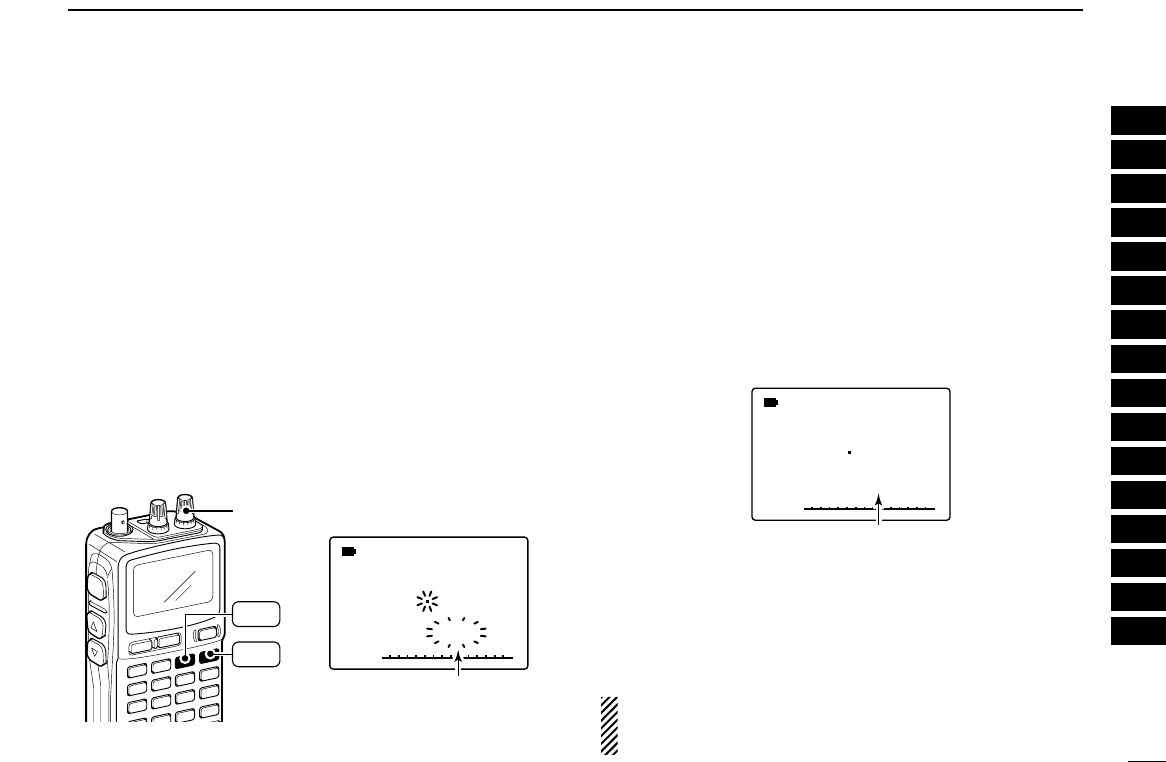
38
7
SCAN OPERATION
■Auto-memory write scan
This scan is useful for searching a specified frequency range
and automatically storing busy frequencies into memory
channels. The auto-memory write scan is performed any VFO
scan types (ALL, BAND, PROG).
qSelect VFO mode with [VFO MHz].
wPush and hold [MODE SCAN] to enter scanning type se-
lection condition.
eRotate [R-DIAL] to select the desired scanning type.
• “ALL” for full scan; “BAND” for band scan, “PROG-xx” for pro-
grammed scan (xx= 0 to 24; programmed scan edges numbers
only displayed)
rRelease [MODE SCAN] to start the scan.
tPush [MR S.MW] to turn the automatic memory write func-
tion ON and OFF.
•“µ” indicator blinks.
yPush [DUALWATCH] to stop the scan.
DDDuring auto-memory write scanning:
• When signal is received, scan pauses and the frequency is
stored into auto-memory write channel group (å000–199).
- 2 short beeps sound when stored.
• Scan resumes after frequency storing.
• When all channels are stored, the scan is canceled auto-
matically and 1 long beep sounds.
DDRecalling the stored frequencies:
qPush [MR S.MW] several times to select the auto-memory
write channel group.
•“ å” appears.
eRotate [R-DIAL] to select the desired channel.
DDClearing the stored frequencies:
qSelect the auto-memory write channel group.
wPush [5 SKIP] for 1 sec. to clear the all channels contents.
• 1 short and 1 long beeps sound.
NOTE: The auto-memory write channel contents CANNOT
be cleared by an independent channel. Thus it is good idea
to copy the contents into regular memory channel.
√
å
MODE ANL
AFCTSQL
FM
439875
P S KIP
-DUP
001
“
å
”
appears when auto memory
write channel group is selected.
√
µ
MODE ANL
AFCTSQL
FM
148800
PSKIP
-DUP
001
• During auto memory
write scan
“ ” indicator blinks during
auto memory write scan.
[R-DIAL]
MODE
SCAN
MR
S.MW
µ
1
2
3
4
5
6
7
8
9
10
11
12
13
14
15
16
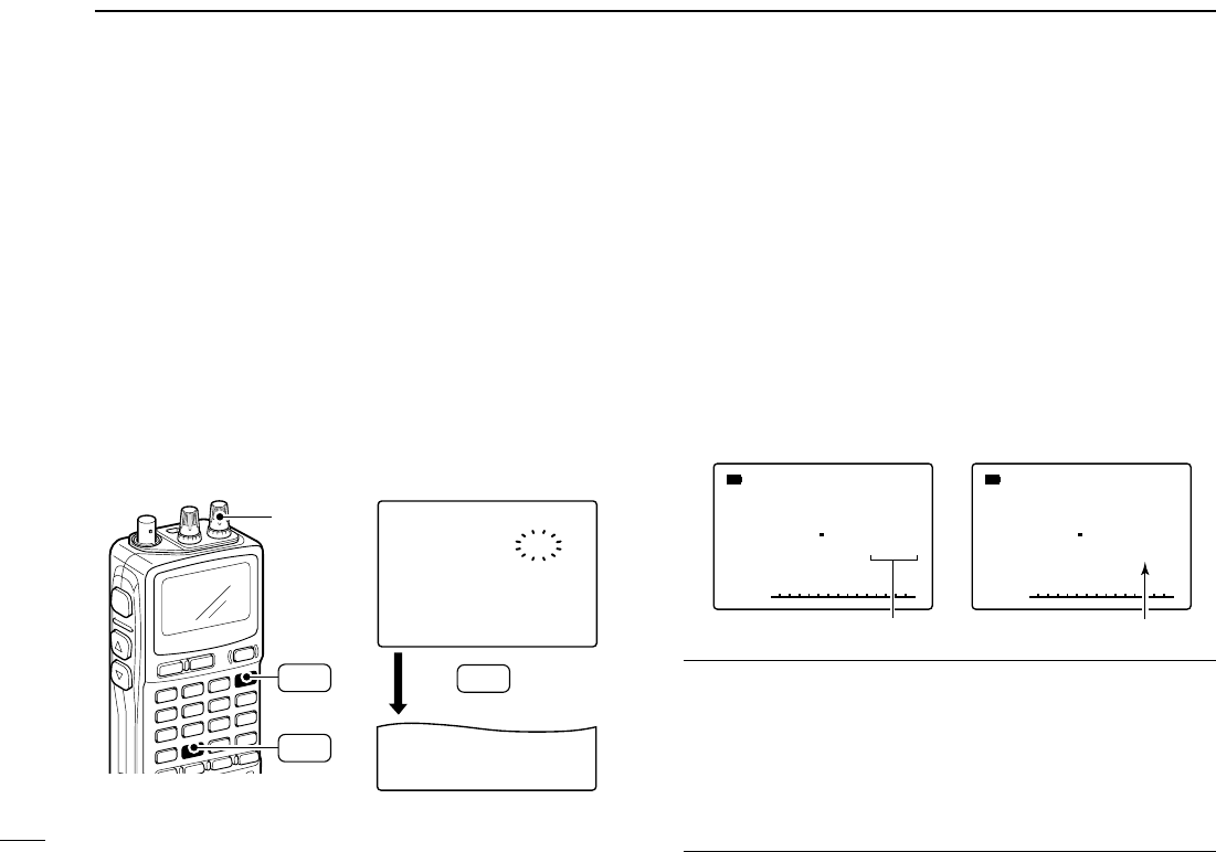
39
7SCAN OPERATION
Memory channels can be set to be skipped for memory skip
scan. In addition, memory channels can be set to be skipped
for both memory skip scan and frequency skip scan. These
are useful to speed up the scan interval.
qSelect a memory channel:
➥Push [MR S.MW] to select memory mode.
➥Rotate [R-DIAL] to select the desired channel to be a
skip channel/frequency.
wPush [MR S.MW] for 1 sec. to enter the select memory
write condition.
ePush [8 SET] several times to select “SKIP” item.
• While pushing [8 SET], rotating [R-DIAL] can also select “SKIP”
item.
rRotate [R-DIAL] to select the skip condition from “SKIP,”
“PSKIP” or “OFF” for the selected channel.
• PSKIP : The channel is skipped during memory/bank scan and
the programmed frequency is skipped during VFO scan,
such as programmed scan.
• SKIP : The channel is skipped during memory or bank scan.
• OFF : The channel or programmed frequency is scanned dur-
ing any scan.
tPush [MR S.MW] for 1 sec. to store the skip condition into
the memory.
• “SKIP” or “PSKIP” indicator appears, according to the skip se-
lection in the step r.
✔
CONVENIENT!
Also the skip setting can be set with the following operation
for easy setting.
qSelect the desired memory channel to be set as a skip
channel/frequency.
w
While pushing [5 SKIP], rotate [R-DIAL] to select the skip
condition from “PSKIP,” “SKIP” and “OFF (no indication).”
ATT
B:GROUP1
√
µ
MODE ANL
AFCTSQL
FM
145700
PSKIP
-DUP
003
ATT
B:GROUP1
√
µ
MODE ANL
AFCTSQL
FM
145700
PSKIP
-DUP
033
• Skip channel setting • Program skip setting
“SKIP”
appears
“PSKIP”
appears
FM
>CLEAR
-SKIP-:OFF
-MNAME:
-BNAME:
>CLEAR
>SKIP-:OFF
-MNAME:
-BANK-:----
012
µ
.
146
.
010
is pushed
several times.
After
[R-DIAL]
SET
8
SET
8
MR
S.MW
■Skip channel/frequency setting
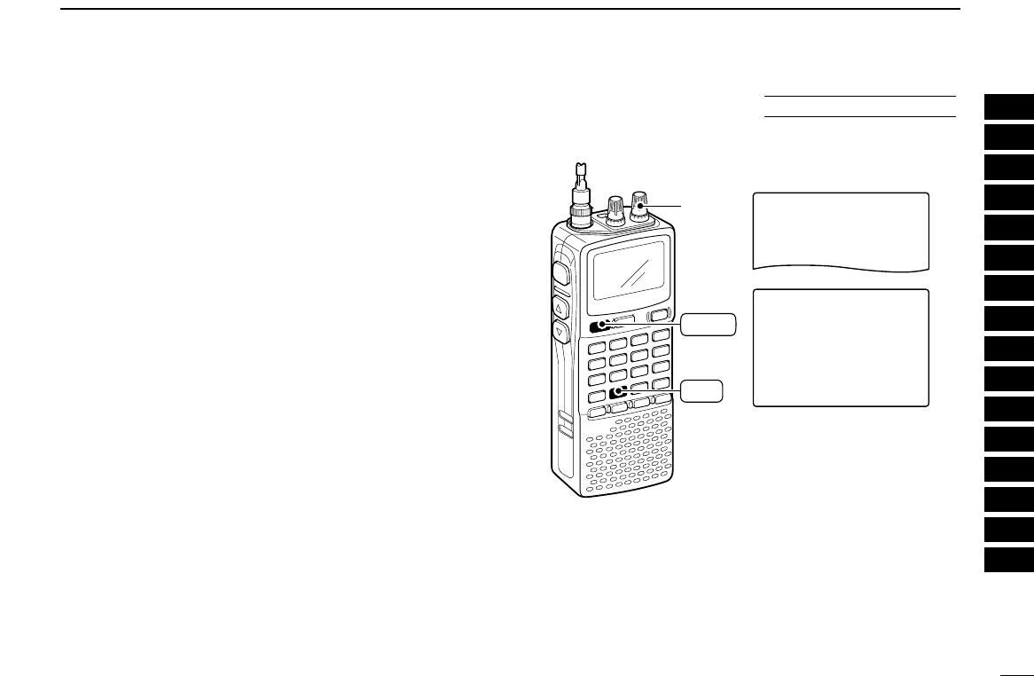
40
7
SCAN OPERATION
DDScan pause timer
The scan pauses when receiving signals according to the
scan pause time. It can be set from 2 to 20 sec. or unlimited.
qPush [8 SET] for 1 sec. to enter set mode.
wRotate [R-DIAL] to select “SET EXPAND” item, then push
[8 SET].
eRotate [R-DIAL] to turn the expand set mode selection
ON, then push [8 SET].
rRotate [R-DIAL] to select “SCAN PAUSE” item, then push
[8 SET].
tRotate [R-DIAL] to set the desired scan time to pause from
2–20 sec. (2 sec. steps) and “HOLD,” then push [8 SET].
• “2SEC”–“20SEC”: Scan pauses for 2–20 sec. while receiving a
signal.
• “HOLD” : Scan pauses on a received a signal until it
disappears.
yPush [DUALWATCH] to exit set mode.
***-SET-MODE-***
-SCAN-RESUME
>SCAN-PAUSE
-AUTO-POWER-OFF
----------------
SCAN-PAUSE
-12SEC
>10SEC
-8SEC
-6SEC
-4SEC
-2SEC
----------------
[R-DIAL]
DUALWATCH
SET
8
■Scan resume condition
IN
EXPANDED SET MODE 1
2
3
4
5
6
7
8
9
10
11
12
13
14
15
16
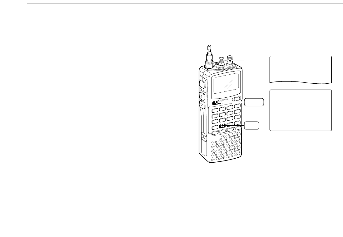
41
7SCAN OPERATION
DDScan resume timer
The scan restarts after the signal disappears according to the
resume time. it can be set from 0–5 sec. or unlimited.
qPush [8 SET] for 1 sec. to enter set mode.
wRotate [R-DIAL] to select “SET EXPAND” item, then push
[8 SET].
eRotate [R-DIAL] to turn the expand set mode selection
ON, then push [8 SET].
rRotate [R-DIAL] to select “SCAN RESUME” item, then
push [8 SET].
tRotate [R-DIAL] to set the desired scan resume timer from
0–5 sec. (1 sec. steps) and “HOLD.”
• “0SEC” : Scan restarts immediately after the signal dis-
appears.
• “1SEC”–“5SEC” : Scan restarts 1–5 sec. after the signal disap-
pears.
• “HOLD” : Scan restarts by rotating [R-DIAL] only.
yPush [DUALWATCH] to exit set mode.
***-SET-MODE-***
-SCAN-STOP-BEEP
>SCAN-RESUME
-SCAN-PAUSE
----------------
SCAN-RESUME
-5SEC
>4SEC
-3SEC
-2SEC
-1SEC
-0SEC
----------------
[R-DIAL]
DUALWATCH
SET
8
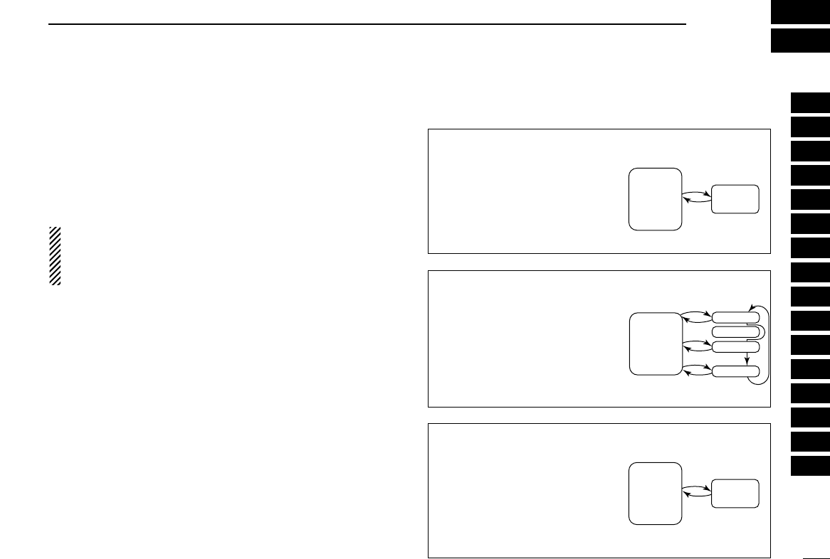
42
8
PRIORITY WATCH
■Priority watch types
Priority watch checks for signals on the frequency every
5 sec. while operating on a VFO frequency or scanning. The
receiver has 3 priority watch types to suit your needs.
The watch resumes according to the selected scan resume
condition. See the left page for details.
NOTES:
If the pocket beep function is activated, the receiver auto-
matically selects the tone squelch function when priority
watch starts.
DDAbout priority beep function
When receiving a signal on the priority frequency, you can be
alerted with beeps and a blink “S.” This function can be
activated when setting the priority watch function ON.
MEMORY CHANNEL WATCH
While operating on a VFO fre-
quency, priority watch checks for
a signal on the selected memory
channel every 5 sec.
• A memory channel with skip infor-
mation can be watched.
MEMORY SCAN WATCH
While operating on a VFO fre-
quency, priority watch checks for
signals on each memory chan-
nel in sequence.
• The memory skip function and/or
memory bank scan is useful to
speed up the scan.
5 sec.
VFO
frequency
Memory
channel
5 sec.
VFO
frequency
SKIP
Mch 000
Mch 001
Mch 001
Mch 999
VFO SCAN WATCH
While scanning on VFO mode,
priority watch checks for signals
on the selected memory chan-
nel every 5 sec.
5 sec.
VFO
scan
Memory
channel
1
2
3
4
5
6
7
8
9
10
11
12
13
14
15
16
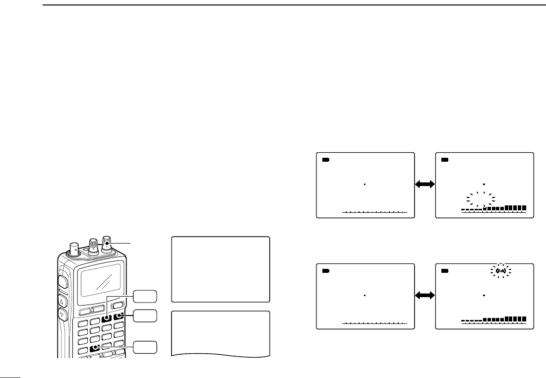
43
8PRIORITY WATCH
■Priority watch operation
DDMemory channel watch and memory scan watch
qSelect VFO mode; then, set an operating frequency.
wSet the watching channel(s).
For memory channel watch:
Select the desired memory channel.
For memory scan watch:
Select memory mode, or the desired bank group; then,
push [MODE SCAN] for 1 sec. to start memory/bank scan.
ePush [8 SET] for 1 sec. to enter set mode.
rRotate [R-DIAL] to select “PRIORITY WATCH” item, then
push [8 SET].
tRotate [R-DIAL] to turn the priority watch ON, then push
[8 SET].
• Select “BELL” if the priority beep function is necessary.
yPush [DUALWATCH] to exit set mode and start the watch.
• “PRIO” indicator appears.
• The receiver checks the memory/bank channel(s) every 5 sec.
• The watch resumes according to the selected scan resume con-
dition. (p. 41)
uPush [DUALWATCH] to cancel the watch.
√
µ
MODE
ANL
AFC
PRIO
TSQL
FM
439975
PSKIP
-DUP
001
√
µ
MODE
ANL
AFC
PRIO
TSQL
FM
145870
PSKIP
-DUP
001
√
µ
MODE
ANL
AFC
PRIO
TSQL
FM
439975
PSKIP
-DUP
001
√
µ
MODE
ANL
AFC
PRIO
TSQL
FM
145870
PSKIP
-DUP
001
• During priority watch
Monitors VFO frequency
for 5 sec.
Pauses on a memory
(bank) channel when a
signal is received.
• During priority watch with priority beep
Emits beep and blinks “S” indicator when a signal is re-
ceived on a memory (bank) channel.
-NOISE-BLANKER
-POWER-SAVE
-BACKLIGHT
-BEEP-LEVEL
-KEY-TOUCH-BEEP
>PRIORITY-WATCH
----------------
PRIORITY-WATCH
-BELL
>ON
-OFF
----------------
***-SET-MODE-***
[R-DIAL]
SET
8
MR
S.MW
MODE
SCAN
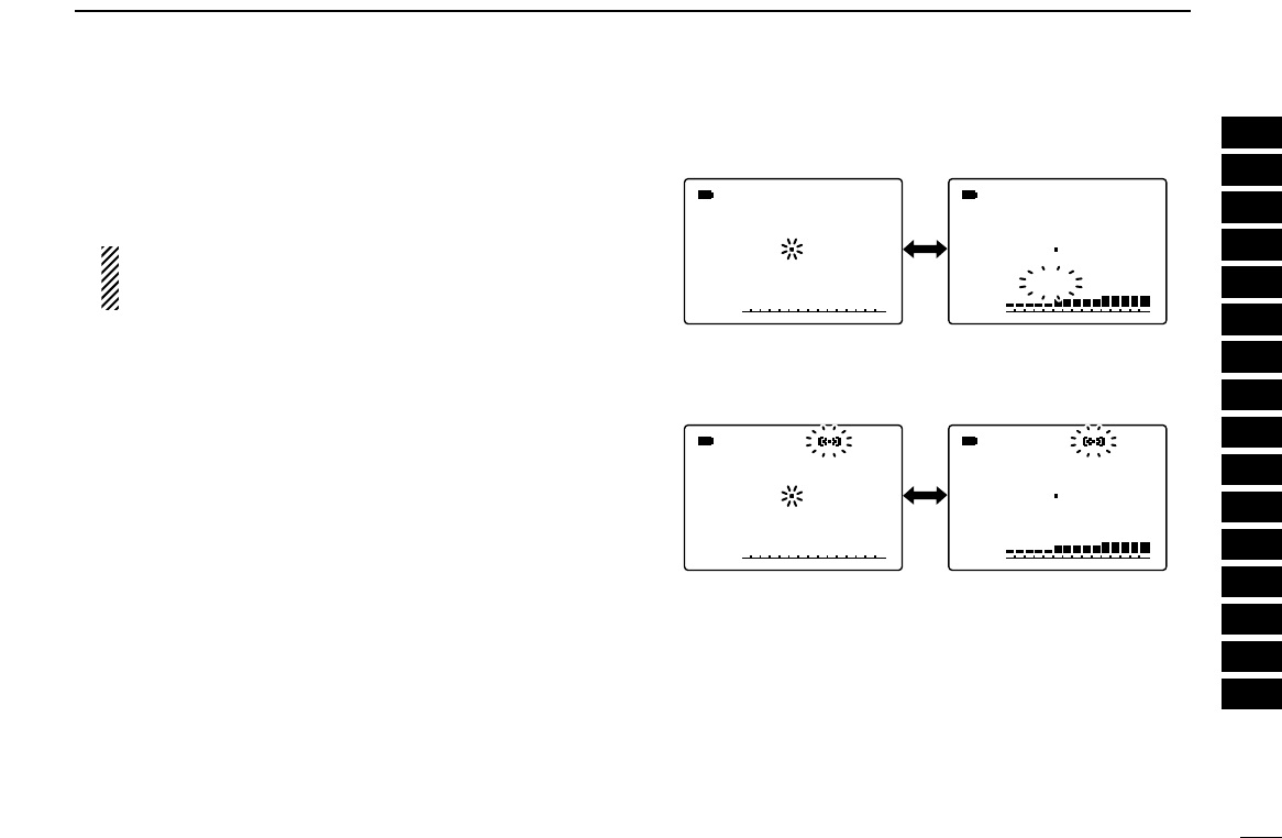
44
8
PRIORITY WATCH
DDVFO scan watch
qSelect memory mode.
• Select a memory bank, if desired.
wPush [MODE SCAN] for 1 sec. to start memory/bank scan,
if desired.
While scanning memory/bank channels:
Starts memory/bank scan first. Memory/bank scan can-
not be started after VFO scan is started.
ePush [8 SET] for 1 sec. to enter set mode.
rRotate [R-DIAL] to select “PRIO” item, then push [8 SET].
tRotate to turn the priority watch ON, then push [8 SET].
• Select “BELL” if the priority beep function is necessary.
yPush [DUALWATCH] to exit set mode and start the watch.
• “PRIO” indicator appears.
uPush and hold [MODE SCAN] to enter scan type selection
condition.
iRotate [R-DIAL] to select the desired scan type from
“ALL,” “BAND” and “PROG-xx (xx= 0–24).”
oRelease [MODE SCAN] to start the VFO scan watch.
• The receiver checks the memory channel(s) every 5 sec.
• The watch resumes according to the selected scan resume con-
dition. (p. 41)
!0Push [DUALWATCH] to cancel the watch and scan.
√
µ
MODE
ANL
AFC
PRIO
TSQL
FM
1888888
PSKIP
-DUP
001
√
µ
MODE
ANL
AFC
PRIO
TSQL
FM
145870
PSKIP
-DUP
001
√
µ
MODE
ANL
AFC
PRIO
TSQL
FM
1888888
PSKIP
-DUP
001
√
µ
MODE
ANL
AFC
PRIO
TSQL
FM
145870
PSKIP
-DUP
001
• During priority watch
Monitors VFO frequency
for 5 sec.
Pauses on a memory
(bank) channel when a
signal is received.
• During priority watch with priority beep
Emits beep and blinks “S” indicator when a signal is re-
ceived on a memory (bank) channel.
1
2
3
4
5
6
7
8
9
10
11
12
13
14
15
16
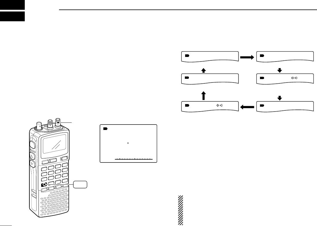
45
COMFORTABLE RECEIVING
9
■Tone/DTCS squelch operation
The tone or DTCS squelch opens only when receiving a sig-
nal with the same pre-programmed subaudible tone or DTCS
code, respectively. You can silently wait for the specified sig-
nal using the same tone.
qSet the desired frequency in FM mode.
wWhile pushing [7 TONE], rotate [R-DIAL] to select the de-
sired subaudible tone condition from “TSQL,” “TSQLS,”
“DTCS” or “DTCSS,” “VSC” and “OFF.”
• One of “TSQL,” “ TSQLS,” “DTCS,” “DTCSS” and “VSC”
appears according to the tone selection.
eWhen a signal with the matched tone is received, the
squelch opens and the receiver emits audio.
When pocket beep function is activated, the receiver also
emits beep tones and blinks “S”.
• Beep tones sound and “S” blinks for 30 sec.
rPush [DUALWATCH] to stop the beeps and blinking man-
ually.
•“S” disappears and the pocket beep function is deactivated.
tTo cancel the tone squelch or DTCS, rotate [R-DIAL] while
pushing [7 TONE] to tone indication disappears.
NOTE: The VSC (Voice Squelch Control) function opens
the squelch only when receiving a modulated signal. This
function is very useful while scanning, the VSC pauses a
only when modulated signals are received. Scanning con-
tinues when unmodulated or beat signals are received.
MODE
AFC
TSQL
FM
-DUP
MODE
AFC
TSQL
FM
-DUP
MODE
AFC
TSQL
FM
-DUP
MODE
AFC
DTCS
FM
-DUP
MODE
AFC
VSC
FM
-DUP
MODE
AFC
DTCS
FM
-DUP
Tone squelch with pocket
beep function selection
DTCS selection
VSC selection
DTCS with pocket beep
function selection
Tone squelch selection
OFF: (No indication)
√
MODE
ANL
AFC
TSQL
FM
145975
PSKIP
-DUP
“TSQL” appears
[R-DIAL]
TONE
7
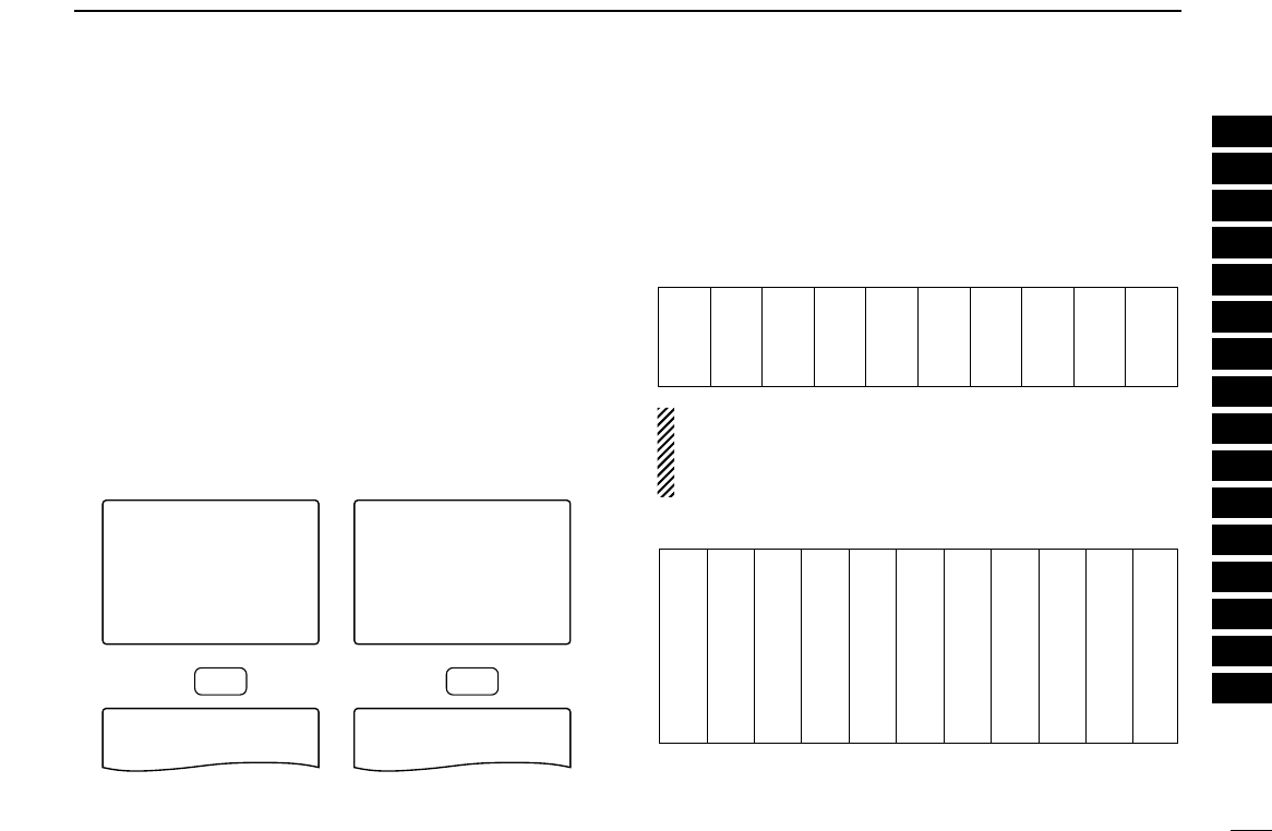
46
9
COMFORTABLE RECEIVING
■Tone squelch frequency/DTCS code setting
88.5 Hz and 023 is set as the default for the tone squelch fre-
quency and the DTCS code, respectively. The frequency and
code can be selected as desired.
qPush [8 SET] for 1 sec. to enter set mode.
wRotate [R-DIAL] to select “SET EXPAND” item, then push
[8 SET].
eRotate [R-DIAL] to turn the expanded set mode ON, then
push [8 SET].
rRotate [R-DIAL] to select “TONE FREQ” item when se-
lecting the tone squelch frequency; select “DTCS CODE”
item when selecting the DTCS code, then push [8 SET].
tRotate [R-DIAL] to select the desired tone squelch fre-
quency or DTCS code, then push [8 SET].
• See the tables at right.
yPush [DUALWATCH] to exit set mode.
•Available tone frequency list
NOTE: The receiver has 50 tone frequencies and conse-
quently their spacing is narrow compared to units having
38 tones. Therefore, some tone frequencies may receive
interference from adjacent tone frequencies.
•Available DTCS code list
023
025
026
031
032
036
043
047
051
053
125
131
132
134
143
145
152
155
156
162
245
246
251
252
255
261
263
265
266
271
356
364
365
371
411
412
413
423
431
432
506
516
523
526
532
546
565
606
612
624
054
065
071
072
073
074
114
115
116
122
165
172
174
205
212
223
225
226
243
244
274
306
311
315
325
331
332
343
346
351
445
446
452
454
455
462
464
465
466
503
627
631
632
654
662
664
703
712
723
731
732
734
743
754
67.0
69.3
71.9
74.4
77.0
79.7
82.5
85.4
88.5
91.5
94.8
97.4
100.0
103.5
107.2
110.9
114.8
118.8
123.0
127.3
131.8
136.5
141.3
146.2
151.4
156.7
159.8
162.2
165.5
167.9
171.3
173.8
177.3
179.9
183.5
186.2
189.9
192.8
196.6
199.5
203.5
206.5
210.7
218.1
225.7
229.1
233.6
241.8
250.3
254.1
-BANK-LINK
-DTCS-POLARITY
-DTCS-CODE
>TONE-FREQ
-DUPLEX
-OFFSET-FREQ
----------------
TONE-FREQ
88.5
----------------
***-SET-MODE-***
-BANK-LINK
-DTCS-POLARITY
>DTCS-CODE
-TONE-FREQ
-DUPLEX
-OFFSET-FREQ
----------------
DTCS-CODE
023
----------------
***-SET-MODE-***
Push
SET
8
Push
SET
8
Tone squelch frequency
selection
DTCS code selection
1
2
3
4
5
6
7
8
9
10
11
12
13
14
15
16
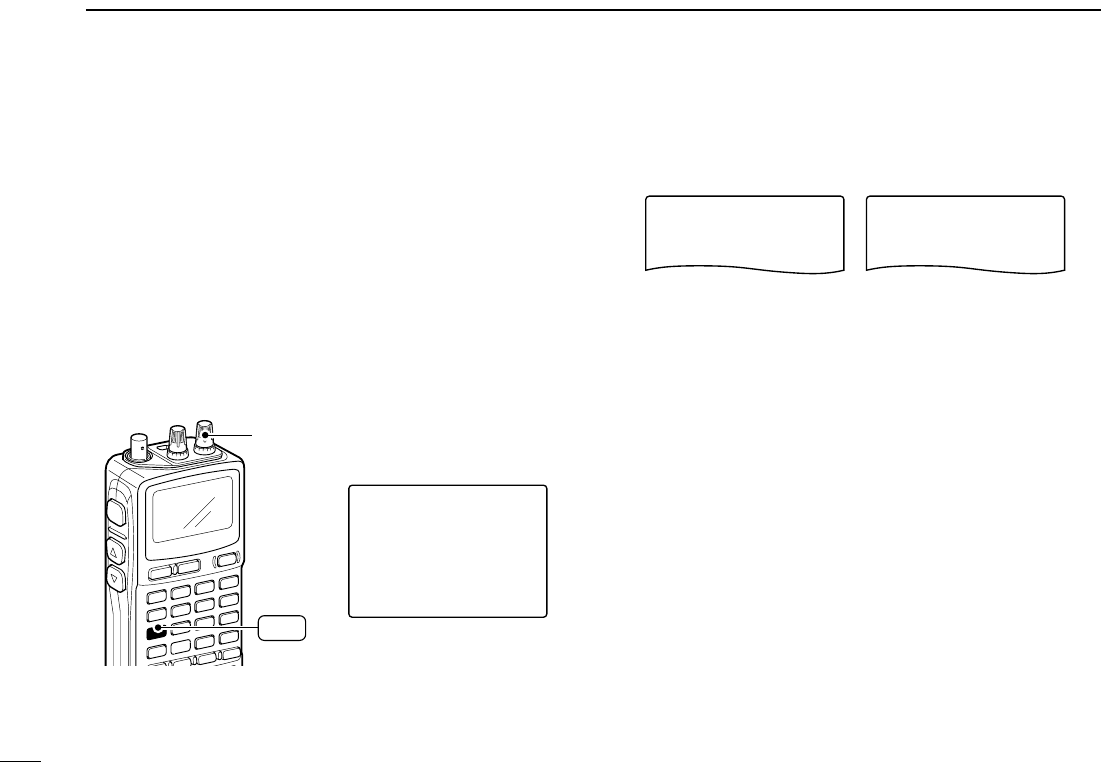
47
9COMFORTABLE RECEIVING
■DTCS polarity setting
As well as the code setting, the polarity setting is also avail-
able for the DTCS operation. When a different polarity is set,
the DTCS never releases audio mute even a signal with
matched code number is received.
qPush [8 SET] for 1 sec. to enter set mode.
wRotate [R-DIAL] to select “SET EXPAND” item, then push
[8 SET].
eRotate [R-DIAL] to turn the expanded set mode ON, then
push [8 SET].
rRotate [R-DIAL] to select “DTCS POLARITY” item, then
push [8 SET].
tRotate [R-DIAL] to select the polarity from “NORMAL” and
“REVERSE,” then push [8 SET].
yPush [DUALWATCH] to exit set mode.
DTCS-POLARITY
-REVERSE
>NORMAL
----------------
DTCS-POLARITY
>REVERSE
-NORMAL
----------------
Normal polarity Reverse polarity
-BANK-LINK
>DTCS-POLARITY
-DTCS-CODE
-TONE-FREQ
-DUPLEX
-OFFSET-FREQ
----------------
***-SET-MODE-***
[R-DIAL]
T-SCAN
4
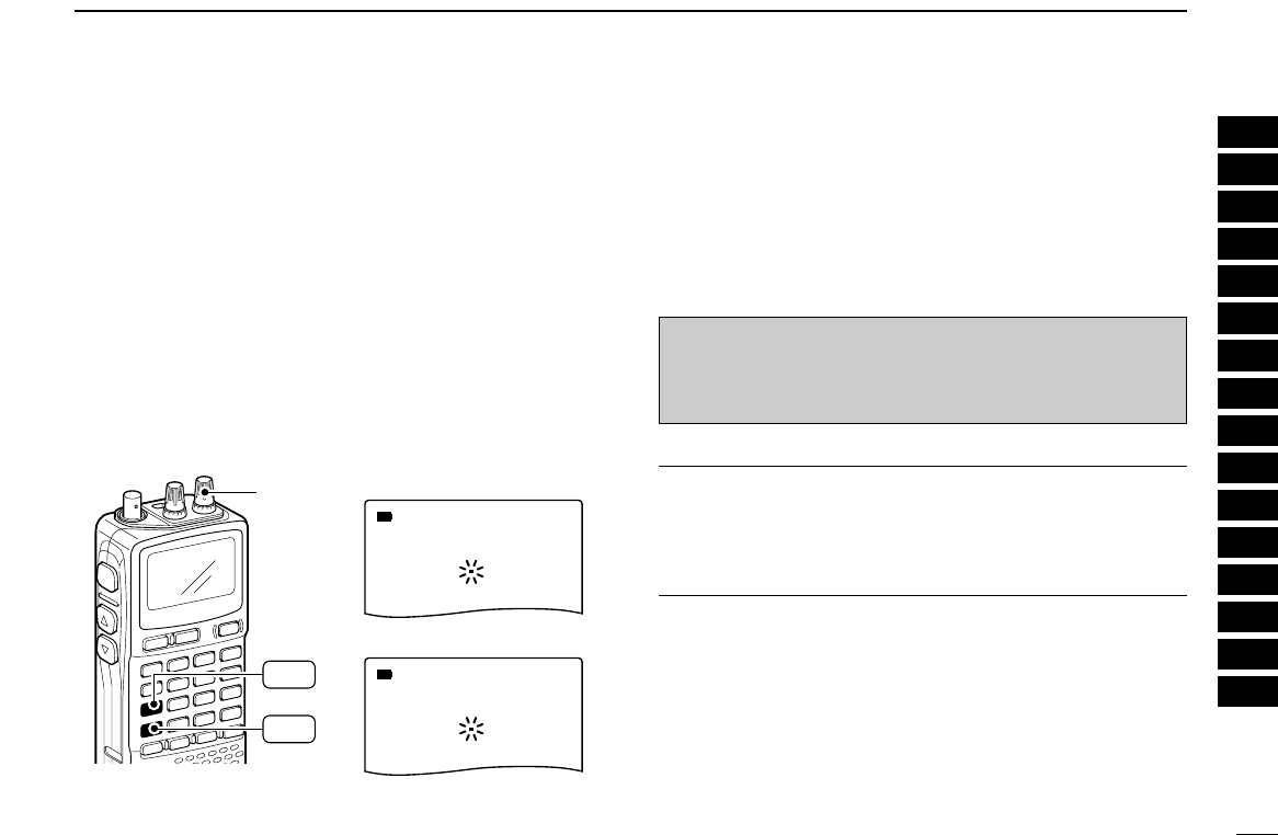
48
9
TONE SQUELCH AND POCKET BEEP
■Tone scan
By monitoring a signal that is being operated with pocket
beep, tone or DTCS squelch function, you can determine the
tone frequency or DTCS code necessary to open a squelch.
qSet the frequency to be checked for a tone frequency or
code.
wTurn the desired tone type, tone squelch or DTCS, ON by
holding [7 TONE] with turning [R-DIAL].
• One of “TSQL” or “DTCS” appears.
• Even the pocket beep function is activated, the function is can-
celled when starts the tone scan.
ePush [4 T-SCAN] for 1 sec. to start the tone scan.
• To change the scanning direction, rotate [R-DIAL].
rWhen the CTCSS tone frequency or 3-digit DTCS code is
matched, the squelch opens and the tone frequency or
code is temporarily programmed into the selected condi-
tion, such as memory channel.
• The tone scan pauses when a CTCSS tone frequency or 3-digit
DTCS code is detected.
✔
For your convenient!
Even no tone type is selected, either tone squelch or DTCS,
pushing [4 T-SCAN] for 1 sec. also start tone scan. In this
case, the tone scan searching for tone squelch frequency
only.
☞NOTE: The decoded tone frequency or code is pro-
grammed temporarily when a memory channel is se-
lected. However, this will be cleared when the memory
channel is re-selected.
√
188 0
√
013
DTCS scan
Tone squelch scan
[R-DIAL]
T-SCAN
4
TONE
7
1
2
3
4
5
6
7
8
9
10
11
12
13
14
15
16
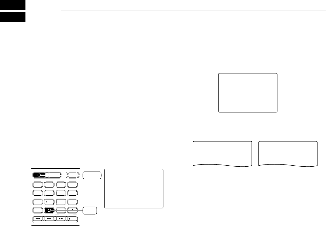
49
SET MODE
10
■General
Set mode is used for programming infrequently changed val-
ues or conditions of functions.
In addition, the IC-R20 has an expanded set mode which is
used for programming even more infrequently changed val-
ues or conditions of functions. When turning the expanded
set mode OFF, only about one thirds of the set mode items
are displayed for simple operation.
DDSet mode entering and operation
qPush [8 SET] for 1 sec. to enter set mode.
wRotate [R-DIAL] to select the desired item, then push
[8 SET].
eRotate [R-DIAL] to select the desired value or condition,
then push [8 SET] to return the setting item selection
mode.
rPush [DUALWATCH] to exit set mode, or rotate [R-DIAL]
to select another set mode item.
DDExpanded set mode ON/OFF
qPush [8 SET] for 1 sec. to enter set mode.
wRotate [R-DIAL] to select “SET EXPAND” item.
ePush [8 SET] to enter “SET EXPAND,” rotate [R-DIAL] to
select the expanded set mode ON and OFF, then push
[8 SET].
rRotate [R-DIAL] to select the desired item.
tPush [8 SET] to enter the item, rotate [R-DIAL] to select
the desired value or condition, then push [8 SET].
yPush [DUALWATCH] to exit set mode, or rotate [R-DIAL]
to select another item.
SET-EXPAND
-ON
>OFF
----------------
SET-EXPAND
>ON
-OFF
----------------
Expanded set mode OFF Expanded set mode ON
***-SET-MODE-***
>SET-EXPAND
-FM-ANTENNA
-AM-ANTENNA
-AF-FILTER
-ANL
-NOISE-BLANKER
----------------
***-SET-MODE-***
-NOISE-BLANKER
-POWER-SAVE
-BACKLIGHT
-BEEP-LEVEL
-KEY-TOUCH-BEEP
>PRIORITY-WATCH
----------------
SET-EXPAND
-ON
>OFF
----------------
SET-EXPAND
>ON
-OFF
----------------
DIAL.SEL SWEEP CENTER
T-SCAN SKIP M.N
TONE SET TS
ATT RF GAIN
IC Recorder
123
4560
789
BAND
DUALWATCH
MAIN/SUB
POWER
VFO
MHz MODE
SCAN MR
S.MW
SCOPE
LOCK
REC
AFC
SET
8
DUALWATCH

50
10
SET MODE
■Set mode items
The following items are available in the set mode and ex-
panded set mode.
DDGeneral set mode items
DDExpanded set mode items
†Available for the USA version only.
***-SET-MODE-***
-DTCS-CODE
>TONE-FREQ
-DUPLEX
-OFFSET-FREQ
-SCOPE-AF-OUTPUT
-SCAN-STOP-BEEP
----------------
***-SET-MODE-***
-WX-ALERT
>LCD-CONTRAST
-BANK-LINK
-DTCS-POLARITY
-DTCS-CODE
-TONE-FREQ
----------------
***-SET-MODE-***
-CI-V-TRANSCEIVE
>CI-V-BAUD-RATE
-CI-V-ADDRESS
-WX-ALERT
-LCD-CONTRAST
-BANK-LINK
----------------
***-SET-MODE-***
-SCAN-RESUME
>SCAN-PAUSE
-AUTO-POWER-OFF
-MONITOR
-DIAL-SPEED-UP
-LOCK
----------------
• Monitor switch action (p. 54)
• Auto power OFF (p. 54)
• Scan pause timer (p. 55)
• Scope audio output (p. 56)
• Duplex direction (p. 56)
• Offset frequency (p. 56)
• Scan stop beep (p. 55)
• Scan resume timer (p. 55)
• Tone frequency (p. 57)
• DTCS code (p. 57)
• DTCS polarity (p. 57)
• LCD contrast (p. 58)
• Memory bank link (p. 58)
• Weather alert† (p. 58)
• CI-V address (p. 58)
• CI-V baud rate (p. 59)
• CI-V transceive (p. 59)
• Key lock effect (p. 49)
• Dial speed acceleration (p. 54)
***-SET-MODE-***
>SET-EXPAND
-FM-ANTENNA
-AM-ANTENNA
-AF-FILTER
-ANL
-NOISE-BLANKER
----------------
***-SET-MODE-***
-NOISE-BLANKER
-POWER-SAVE
-BACKLIGHT
-BEEP-LEVEL
-KEY-TOUCH-BEEP
>PRIORITY-WATCH
----------------
• Priority watch (p. 51)
• Key-touch beep (p. 51)
• Beep output level (p. 51)
• Display backlighting (p. 51)
• Expanded set mode (p. 49)
• Noise blanker (p. 52)
• ANL function (p. 52)
• AF filter (p. 52)
• AM antenna selection (p. 53)
• FM antenna selection (p. 53)
• Power save (p. 52)
1
2
3
4
5
6
7
8
9
10
11
12
13
14
15
16
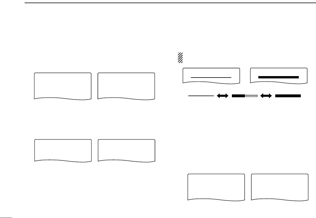
51
10 SET MODE
DDPriority watch
Turn the priority watch or priority beep (priority watch with
beep emission capability) ON. (default: OFF)
• ON : Start priority watch after exiting set mode.
• BELL : Emits beeps and blinking “S” indicator when
a signal is received on the priority frequency.
DDKey-touch beep
The key-touch beep can be turned OFF for silent operation.
(default: ON)
DDBeep output level
Adjust the key-touch beep tone level to the desired level
within 81 levels.
The key-touch beep (previous item) must be set to ON to
have a beep tone.
DDDisplay backlighting
The receiver has display backlighting and function key illumi-
nation with a 5 sec. timer for nighttime operation. The back-
lighting can be turned ON continuously or turned OFF, if
desired.
• AUTO : Lights when some operation is performed, goes
out after 5 sec. (default)
• ON : Lights continuously during receiver power is ON.
• OFF : Never lights.
BACKLIGHT
>ON
-OFF
----------------
BACKLIGHT
-ON
-OFF
-AUTO >AUTO
----------------
Auto setting
Continuously ON setting
BEEP-LEVEL BEEP-LEVEL
Minimum level (no audio) Maximum level
KEY-TOUTCH-BEEP
-ON
>OFF
----------------
KEY-TOUTCH-BEEP
>ON
-OFF
----------------
Key-touch beep OFF Key-touch beep ON
PRIORITY-WATCH
>ON
-OFF
----------------
PRIORITY-WATCH
-ON
-OFF
-BELL >BELL
----------------
Priority watch ON Priority beep ON

52
10
SET MODE
DDPower save
The power save function reduces the current drain to con-
serve battery power. This power save function can be turned
OFF, if desired.
In the default setting (“AUTO” selection), the power save func-
tion is activated in 1:4 (125 msec.: 500 msec.) ratio when no sig-
nal is received for 5 sec. The ratio becomes 1:8 (125 msec.:
1 sec.) when no signal is received for another 60 sec.
DDNoise blanker
The noise blanker reduces pulse-type noise such as that gen-
erated by automobile ignition systems. This function is only
effective for SSB/CW modes and not effective for non pulse-
type noise.
• OFF : The noise blanker function is turned OFF.
(default)
• ON : The noise blanker function is turned ON.
DDANL function
The ANL (Automatic Noise Limitter) function reduces noise
components when AM is selected.
• OFF : The ANL function is turned OFF.
(default)
• ON : The ANL function is turned ON.
DDAF filter
The AF filter suppresses high-pitch tone when this setting is
ON. This function is not effective for FM mode.
• OFF : The AF filter is disactivate. (default)
• ON : The AF filter is activate.
AF-FILTER
-ON
>OFF
----------------
AF-FILTER
>ON
-OFF
----------------
AF filter is ON
AF filter is OFF
ANL
-ON
>OFF
----------------
ANL
>ON
-OFF
----------------
ANL function is ON
ANL function is OFF
NOISE BLANKER
-ON
>OFF
----------------
NOISE BLANKER
>ON
-OFF
----------------
Noise blanker is ON
Noise blanker is OFF
POWER-SAVE
-AUTO
>OFF
----------------
POWER-SAVE
>AUTO
-OFF
----------------
Power save ONPower save OFF
1
2
3
4
5
6
7
8
9
10
11
12
13
14
15
16
53
10 SET MODE
DDAM antenna selection
This setting is activated only for the AM broadcast band,
0.495–1.620 MHz (differ according to version) reception.
• EXT : Use the antenna connected to the antenna con-
nector. (default)
• BAR : Use the internal bar antenna for AM broadcast
band reception.
DDFM antenna selection
This setting is activated only for the FM broadcast band,
76.000–107.995 MHz (differ according to version), recep-
tion.
• EXT : Use the antenna connected to the antenna
connector. (default)
• EARPHONE: Use the connected earphone’s cable as
the antenna for FM broadcast band recep-
tion.
DDKey lock effect
While the key lock function is ON, [VOLUME] and [SQL] can
still be accessed. Accessible keys can be set to one of 4
groups.
[POWER] and [•LOCK] are also accessible during the lock,
however, these keys are not effected by this setting.
• NORMAL : [VOLUME] and [SQL] are accessible.
(default)
• NO SQL : [SQL] is accessible.
• NO VOL : [VOLUME] are accessible.
• ALL : No accessible key is available, except
[POWER] and [• LOCK].
LOCK
-NO-SQL
-NORMAL
----------------
LOCK
-NO-SQL
-NORMAL
>NO-VOL -NO-VOL
-ALL >ALL
----------------
LOCK
-NO-SQL
>NORMAL
----------------
LOCK
>NO-SQL
-NORMAL
-NO-VOL -NO-VOL
-ALL -ALL
----------------
Normal lock condition
Audio output can be adjusted
Squelch level can be adjusted
Receiver power and lock
function only switchable
FM-ANTENNA
-EARPHONE
>EXT
----------------
FM-ANTENNA
>EARPHONE
-EXT
----------------
External antenna Connected earphone cable
AM-ANTENNA
-BAR
>EXT
----------------
AM-ANTENNA
>BAR
-EXT
----------------
External antenna Internal bar antenna

54
10
SET MODE
DDDial speed acceleration
The dial speed acceleration automatically speeds up the tun-
ing dial speed when rotating [R-DIAL] rapidly.
• OFF : The dial speed acceleration is turned OFF.
• ON : The dial speed acceleration is tuned ON.
(default)
DDMonitor key action
The monitor key, [SQL], can be set as a ‘sticky’ key. When
set to the sticky condition, each push of [SQL] toggles the
monitor function ON and OFF.
• PUSH : Pushing and holding [SQL] to monitor the fre-
quency. (default)
• HOLD : Push [SQL] momentarily to monitor the fre-
quency and push momentarily again to cancel it.
DDAuto power OFF
The receiver can be set to automatically turn OFF after a
specified period is past.
30 min., 1 hour, 1.5 hours, 2 hours, BUSY and OFF (default)
can be specified. The specified period is retained even when
the receiver is turned OFF by the auto power OFF function.
To cancel the function, select “OFF” in this set mode.
• 30–120: The receiver automatically turns OFF (with a
beep) after a specified period from last key op-
eration.
• BUSY : The receiver automatically turns OFF (with a
beep) after 3 minutes from last key operation or
signal reception.
AUTO-POWER-OFF
>30MIN
-OFF
----------------
AUTO-POWER-OFF
-30MIN
-OFF
-90MIN
-60MIN
-90MIN
-60MIN
-BUSY >BUSY
-120MIN -120MIN
----------------
30 min. timer 2 hrs. timer
MONITOR
-HOLD
>PUSH
----------------
MONITOR
>HOLD
-PUSH
----------------
Push and hold [SQL] to monitorPush to monitor
DIAL-SPEED-UP
-ON
>OFF
----------------
DIAL-SPEED-UP
>ON
-OFF
----------------
The acceleration ONThe acceleration OFF
1
2
3
4
5
6
7
8
9
10
11
12
13
14
15
16

55
10 SET MODE
DDScan pause timer
Selects the scan pause time. When receiving signals, the
scan pauses according to the scan pause time.
• 2–20 : Scan pauses for 2–20 sec. on a received signal,
and selected in 2 sec. steps. (default: 10 sec.)
• HOLD : Scan pauses on a received signal until it disap-
pears. Rotate [R-DIAL] to resume manually.
DDScan resume timer
Selects scan resume time. Scan resumes after the specified
period when the received signal disappears.
• 0 : Scan resumes immediately when the received
signal disappears.
• 1–5 : Scan pause 1–5 sec. after the received signal
disappears. (default: 2 sec.)
• HOLD : Scan pauses on the received signal even if it dis-
appears. Rotate [R-DIAL] to resume manually.
DDScan stop beep
Turns the scan stop beep function ON and OFF.
When the function is activated (“ON” is selected), a long beep
will sounds each time when signal is received during scan.
SCAN-STOP-BEEP
-ON
>OFF
----------------
SCAN-STOP-BEEP
>ON
-OFF
----------------
No beep is sound when
receiving a signal
A long beep is sound when
receiving a signal
SCAN-RESUME
-1SEC
-0SEC
----------------
SCAN-RESUME
-2SEC
-1SEC
-3SEC
>2SEC
-4SEC
-3SEC
-5SEC >HOLD
-4SEC -5SEC
----------------
Scan resumes after 2 sec. Scan resumes manually
SCAN-PAUSE
-4SEC
-2SEC
----------------
SCAN-PAUSE
-14SEC
-12SEC
-8SEC
-6SEC
-18SEC
-16SEC
-12SEC >HOLD
>10SEC -20SEC
----------------
Scan pauses for 10 sec. Scan pauses until signal
disappears

56
10
SET MODE
DDScope audio output
Sets the audio output function while scope operation.
The scope audio output is used for finding out the signals
while scope function are modulated, unmodulated or beet
signal etc.
DDOffset frequency
Sets the duplex offset frequency for each frequency band in-
dependently within 0 to 159.99999 MHz range. During duplex
operation (–DUP or +DUP), the monitoring frequency (while
[SQL] is pushed) shifts the set frequency.
The default value may differ according to the selected fre-
quency band (before accessing set mode) and receiver version.
The selected tuning step in VFO mode is used for the off-
set frequency setting.
DDDuplex direction
Sets the duplex direction. The displaying frequency shifts the
programmed offset frequency (at left below) when monitor
function is in use (while pushing [SQL]).
• OFF : Simplex operation. (default)
• –DUP : The displaying frequency shifts down dur-
ing monitor.
• +DUP : The displaying frequency shifts up during
monitor.
DUPLEX
--DUP
>OFF
-+DUP
----------------
DUPLEX
--DUP
-OFF
>+DUP
----------------
Simplex operation Positive duplex operation
OFFSET-FREQ
----0.000.00
OFFSET-FREQ
159.999.99
---------------- ----------------
----------------
SCOPE-AF-OUTPUT
-ON
>OFF
----------------
SCOPE-AF-OUTPUT
>ON
-OFF
----------------
----------------
No audio output while
sweep operation
AF output while
sweep operation
1
2
3
4
5
6
7
8
9
10
11
12
13
14
15
16
57
10 SET MODE
DDTone frequency
Sets subaudible tone frequency for tone squelch operation.
Total of 50 tone frequencies (67.0–254.1 Hz) are available.
(default: 88.5 Hz)
•Available subaudible tone frequencies
DDDTCS code
Sets DTCS code for DTCS squelch operation. Total of 104
codes (023–754) are available. (default: 023)
•Available DTCS code
The polarity can also be set in “DTCS polarity” as follow.
DDDTCS polarity
Sets DTCS polarity from normal and reverse.
(default: NORMAL)
DTCS-POLARITY
-REVERSE
>NORMAL
----------------
DTCS-POLARITY
>REVERSE
-NORMAL
----------------
Normal setting Reverse setting
023
025
026
031
032
036
043
047
051
053
125
131
132
134
143
145
152
155
156
162
245
246
251
252
255
261
263
265
266
271
356
364
365
371
411
412
413
423
431
432
506
516
523
526
532
546
565
606
612
624
054
065
071
072
073
074
114
115
116
122
165
172
174
205
212
223
225
226
243
244
274
306
311
315
325
331
332
343
346
351
445
446
452
454
455
462
464
465
466
503
627
631
632
654
662
664
703
712
723
731
732
734
743
754
DTCS-CODE
-023
DTCS-CODE
-754
---------------- ----------------
Code 023 setting Code 754 setting
67.0
69.3
71.9
74.4
77.0
79.7
82.5
85.4
88.5
91.5
94.8
97.4
100.0
103.5
107.2
110.9
114.8
118.8
123.0
127.3
131.8
136.5
141.3
146.2
151.4
156.7
159.8
162.2
165.5
167.9
171.3
173.8
177.3
179.9
183.5
186.2
189.9
192.8
196.6
199.5
203.5
206.5
210.7
218.1
225.7
229.1
233.6
241.8
250.3
254.1
TONE-FREQ
--88.5
TONE-FREQ
254.1
---------------- ----------------
88.5 Hz setting 254.1 Hz setting
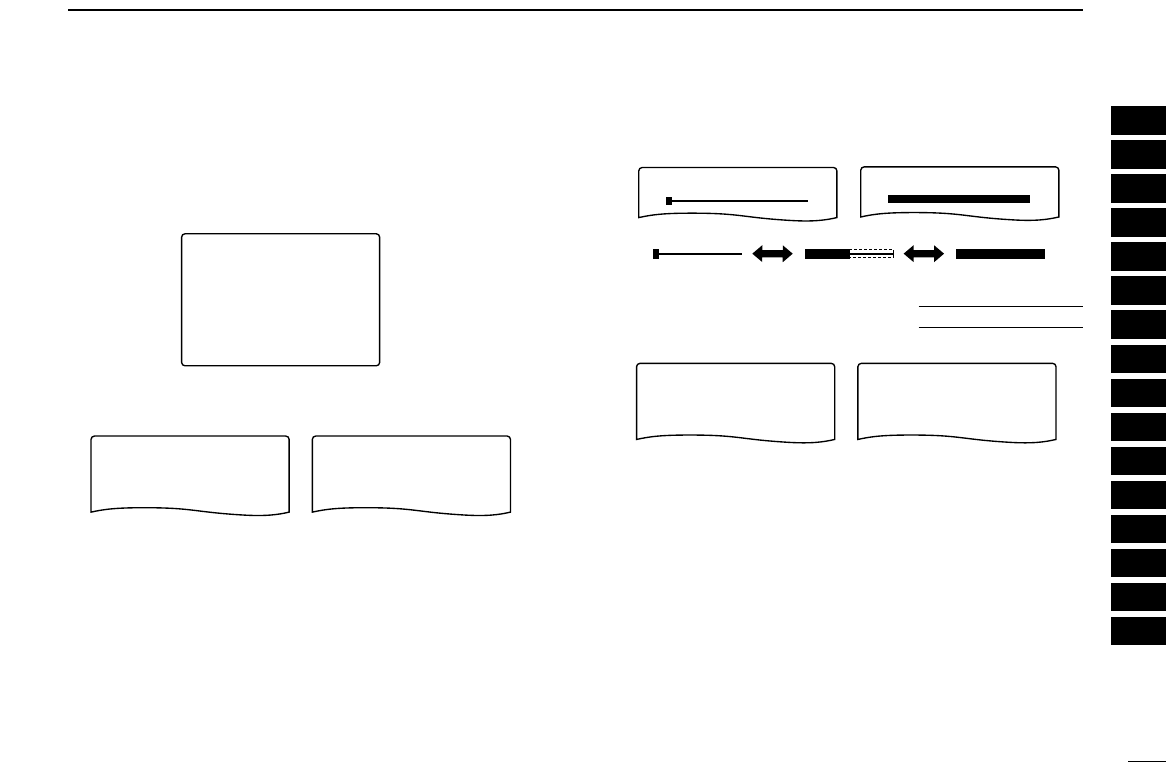
58
10
SET MODE
1
2
3
4
5
6
7
8
9
10
11
12
13
14
15
16
DDMemory bank link
Sets the linked bank for the bank-link scan.
(default: All banks are ON)
qRotate [R-DIAL] to select the bank that you want to change
setting.
wPush [8 SET] for 1 sec. to enter the bank link setting con-
dition.
eRotate [R-DIAL] to select the setting, then push [8 SET].
rRotate [R-DIAL] to select next bank and repeat qto e, or
push [DUALWATCH] to exit set mode.
DDLCD contrast
The LCD contrast can be adjusted through 15 levels.
DDWeather alert function
Turns weather alert function ON and OFF.
WX-ALERT
-ON
>OFF
----------------
WX-ALERT
>ON
-OFF
----------------
Weather alert OFF Weather alert ON
U.S.A. version only
LCD-CONTRAST
LCD-CONTRAST
Minimum level Maximum level
BANK-A
-ON
>OFF
----------------
BANK-A
>ON
-OFF
----------------
When OFF is selected When ON is selected
BANK-A
-ON
>OFF
----------------
BANK-A
>ON
-OFF
----------------
BANK-LINK
-BANK-B:ON
>BANK-A:ON
----------------
-BANK-D:ON
-BANK-C:ON
-BANK-F:ON
-BANK-E:ON

59
10 SET MODE
DDCI-V address
To distinguish equipment, each CI-V transceiver/receiver has
its own Icom standard address in hexadecimal code. The IC-
R20’s address is “6C.’
When 2 or more IC-R20s are connected to an optional CT-17
CI
-
V LEVEL CONVERTOR
, set a different address for each IC-
R20 in the range “01” to “7F.” (default: 6C)
DDCI-V boud rate
Sets the data transfer rate. When “AUTO” is selected, baud
rate is automatically set according to the connected controller
or other Icom CI-V radio. (default: AUTO)
DDCI-V transceive
CI-V transceive operation is possible with the IC-R20 con-
nected to an Icom CI-V radio. When “ON” is selected, chang-
ing the frequency, operating mode, etc. on the IC-R20
automatically changes those of connected radios and vice
versa. (default: ON)
CI-V-TRANSCEIVE CI-V-TRANSCEIVE
-ON
>OFF
----------------
>ON
-OFF
----------------
CI-V transceive OFF CI-V transceive ON
CI-V-BAUD-RATE
-1200bps
-300bps
-9600bps
-4800bps
-19200bps
>AUTO
-1200bps
-300bps
>9600bps
-4800bps
-19200bps
-AUTO
----------------
CI-V-BAUD-RATE
----------------
“AUTO” baud rate setting 9600 bps setting
CI-V-ADDRESS
-6C
----------------
CI-V-ADDRESS
-01
----------------
CI-V address set to 6C CI-V address set to 01
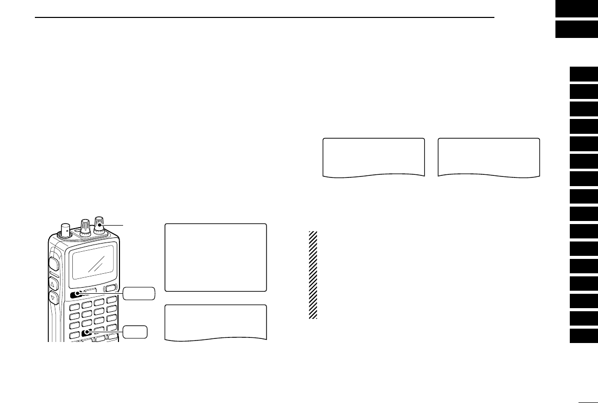
60
11
OTHER FUNCTIONS
■Antenna selection
The IC-R20 has an internal bar antenna for receiving AM
broadcast band (0.495–1.620 MHz) signals. In addition, the
connected earphone’s cable can be used as an antenna for
receiving FM broadcast band (76.000–107.995 MHz; differ ac-
cording to version) signals.
DDSelecting antenna
qPush [8 SET] for 1 sec. to enter set mode.
wRotate [R-DIAL] to select “AM ANTENNA” or “FM AN-
TENNA” item for AM broadcast band or FM broadcast
band, respectively.
eAfter pushing [8 SET], rotate [R-DIAL] to select “BAR”
when “AM ANTENNA” is selected for the AM broadcast
band; select “EARPHONE” when “FM ANTENNA” is se-
lected for the FM broadcast band.
yPush [DUALWATCH] momentarily to exit set mode.
NOTE:
•Some noise or spurious may be received when the inter-
nal bar or earphone cable is used for antenna.
• The supplied or third party’s antenna MUST BE con-
nected to the antenna connector to receive signals other
than AM or FM broadcast bands.
• When receiving an AM broadcast signal with internal bar
antenna, aim the receiver to better audio direction.
• When the internal bar or earphone cable is used for an an-
tenna, the attenuator function cannot be used.
>BAR
-EXT
----------------
AM-ANTENNA
>EARPHONE
-EXT
----------------
FM-ANTENNA
Bar antenna selection for
0.495–1.620 MHz band
Earphone cable selection for
76.000–107.995 MHz band
***-SET-MODE-***
-BAR
>EXT
----------------
AM-ANTENNA
-SET-EXPAND
-FM-ANTENNA
>AM-ANTENNA
-AF-FILTER
-ANL
-NOISE-BLANKER
----------------
[R-DIAL]
DUALWATCH
SET
8
1
2
3
4
5
6
7
8
9
10
11
12
13
14
15
16
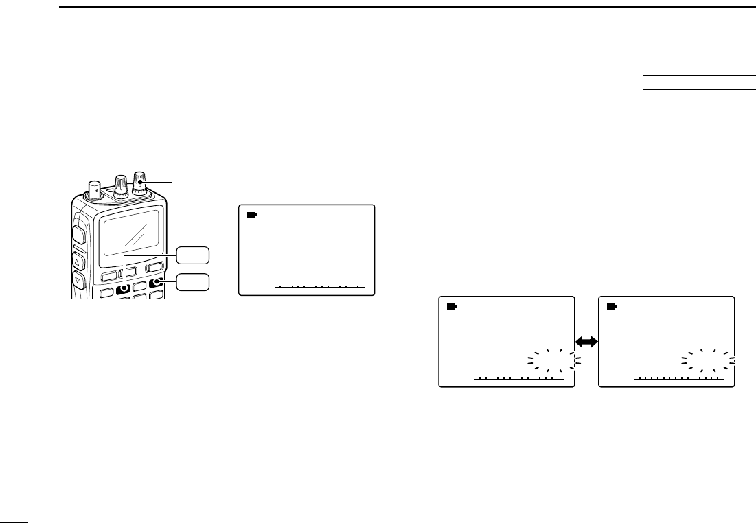
61
11 OTHER FUNCTIONS
DDWeather channel selection
qPush [MR S.MW] several times to select the weather chan-
nel group.
wRotate [R-DIAL] to select the desired weather channel.
rPush [VFO MHz] to return to VFO mode, or push [MR
S.MW] to select other mode to exit the weather channel.
DDWeather alert function
NOAA broadcast stations transmit weather alert tones before
important weather announcements. When the weather alert
function is turned ON, the selected weather channel is moni-
tored each 5 sec. for the announcement. When the alert signal
is detected, the “ALT” and the “WX” indications are displayed
alternately and sounds a beep tone until the receiver is oper-
ated. The previously selected (used) weather channel is
checked periodically during standby or while scanning.
qSelect the desired weather channel.
wTurn the weather alert function ON in set mode.
➥Push [8 SET] for 1 sec. to enter set mode.
➥Rotate [R-DIAL] to select “WX ALERT” item, then push
[8 SET]. Rotate [R-DIAL] to select “ON.”
➥Push [DUALWATCH] to exit set mode.
eSet the desired stand-by condition.
• Select VFO or memory channel.
• Scan or priority watch operation can also be selected.
rWhen the alert is detected, a beep sounds and the follow-
ing indication will be displayed.
tTurn the weather alert function OFF in set mode.
√
MODE ANL
AFCTSQL
FM
PSKIP
-DUP
WX
√
MODE ANL
AFCTSQL
FM
PSKIP
-DUP
ALT
1 1
Show above indications alternately.
√
MODE ANL
AFCTSQL
FM
1
PSKIP
-DUP
WX
Weather channel indication
[R-DIAL]
MR
S.MW
VFO
MHz
■Weather channel operation U.S.A. version only
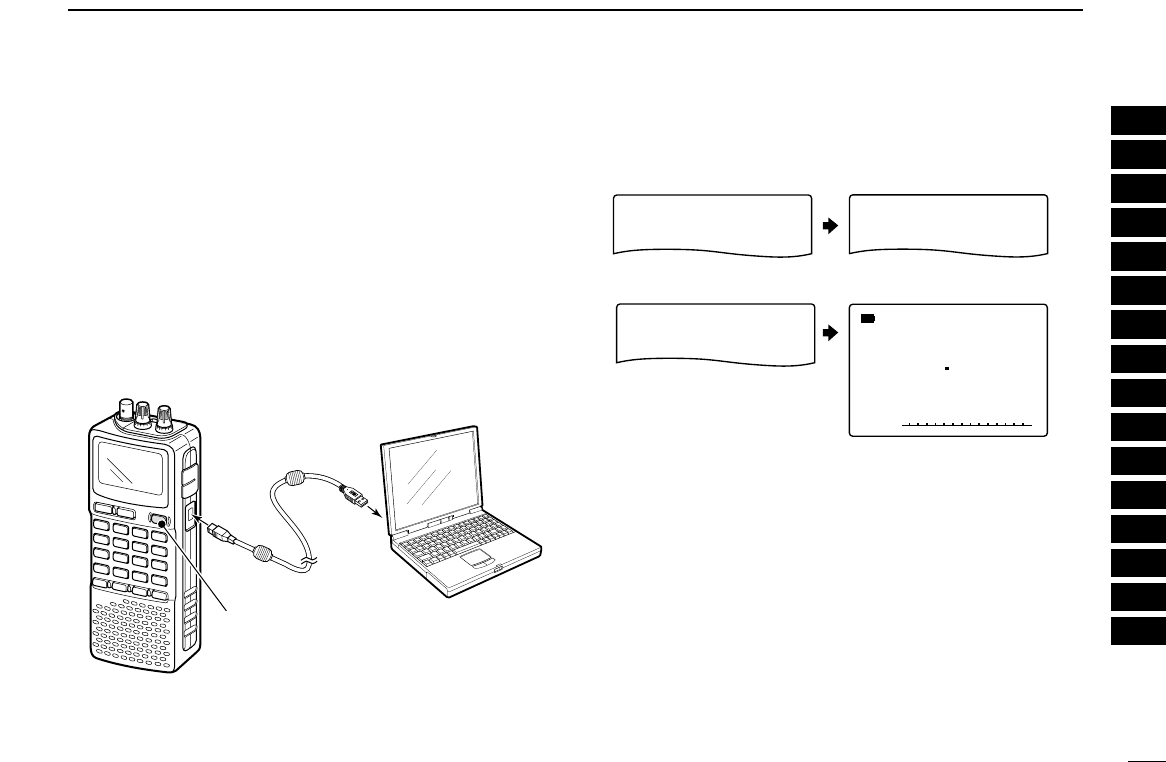
62
11
OTHER FUNCTIONS
■Data cloning
Cloning allows you to quickly and easily transfer the pro-
grammed contents from a personal computer to a receiver
using the optional CS-R20
CLONING SOFTWARE
.
DCloning using a personal computer
Data can be cloned to and from a personal computer (Mi-
crosoft®Windows®98/Me/2000/XP) using the optional CS-
R20
CLONING SOFTWARE
and the optional OPC-1382
CLONING
CABLE
. Consult the CS-R20
CLONING SOFTWARE
HELP file for
details.
• The receiver show following indications.
CLONE-OUT
CLONE
CLONE-IN
√
MODE ANL
AFCTSQL
FM
146010
PSKIP
-DUP
During cloning
During cloning
After cloning
After cloning
Read from receiver
Write to receiver
IC-R20
PC
to USB
port
OPC-1382
to USB
jack
Push to turn power ON.
Microsoft and Windows are registered trademarks of Microsoft Corporation in
the U.S.A. and other countries.
1
2
3
4
5
6
7
8
9
10
11
12
13
14
15
16
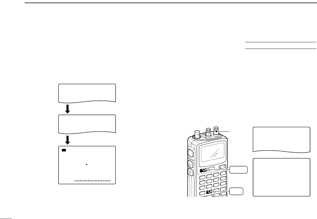
63
11 OTHER FUNCTIONS
DCloning error
☞NOTE: DO NOT push any key on the sub-receiver during
cloning. This will cause a cloning error.
When the display appears as below, a cloning error has oc-
curred.
In such a case, the receiver automatically performs ALL
RESET while turning power OFF and ON.
■Auto power-off function
The IC-R20 can be set to automatically turn OFF after a spec-
ified period in which no operation is performed.
BUSY, 120 min., 90 min., 60 min., 30 min. and OFF can be
specified. The specified period is retained even when the re-
ceiver is turned OFF by the auto power-off function. To cancel
the function, select “OFF” in step ebelow.
qPush [8 SET] for 1 sec. to enter set mode.
wRotate [R-DIAL] to select “AUTO POWER OFF” item, then
push [8 SET].
• Turn the expanded set mode ON for selection. (p. 49)
eRotate [R-DIAL] to select the desired time or to turn the
function OFF, then push [8 SET].
rPush [DUALWATCH] to exit set mode.
***-SET-MODE-***
-SCAN-PAUSE
>AUTO-POWER-OFF
-MONITOR
----------------
AUTO-POWER-OFF
>BUSY
-120MIN
-90MIN
-60MIN
-30MIN
-OFF
----------------
[R-DIAL]
DUALWATCH
SET
8
USING
EXPANDED SET MODE
√
MODE ANL
AFCTSQL
FM
146010
PSKIP
-DUP
ALL-RESET
CLONE-ERROR
Turn power OFF, then ON
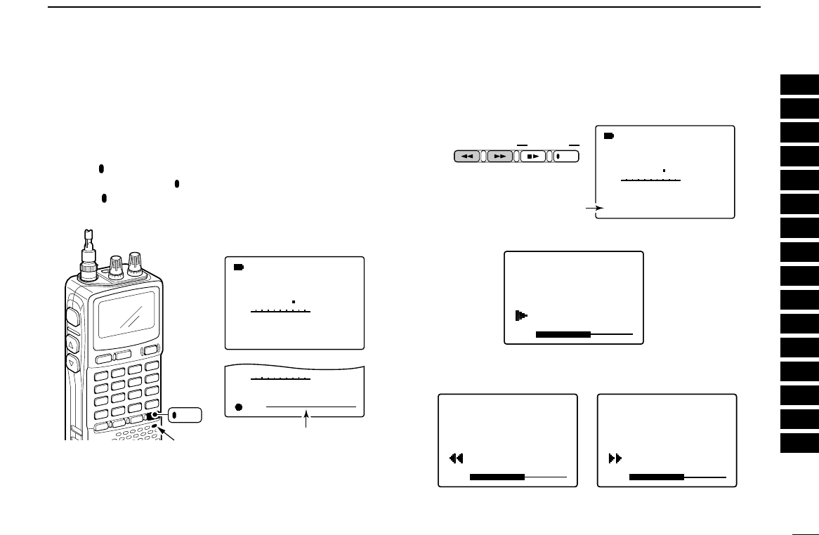
64
11
OTHER FUNCTIONS
■IC recorder
The IC-R20 has an IC recorder of up to 32 tracks. The maxi-
mum recording length is about 260 minutes.
DDRecording a received audio
qPush [ REC] momentarily to start recording.
• Red LED below the [ REC] lights ON.
wPush [ REC] momentarily to pause to record or push
[■
≈≈
]to stop recording.
DDPlaying recorded audio
qPush [
ΩΩΩΩ
ATT]/[
≈≈≈≈
RF GAIN] to select the desired track.
• The track number appears.
wPush [■
≈≈
]momentarily to start playing the track.
ePush [
ΩΩΩΩ
ATT] when you want to rewind; or [
≈≈≈≈
RF
GAIN] when you want to skip while playing.
rPush [■
≈≈
]to stop playing.
• Even you don’t push [■
≈≈
], the receiver stops automatically and
returns to normal condition at the end of the track.
VOL
TRACK:01
NORMAL
---------------
0:00:30/0:12:14
x1.00
---------------
81
VOL
TRACK:01
NORMAL
---------------
0:00:30/0:12:14
x1.00
---------------
81
VOL
√
MODE ANL
AFCTSQL
FM
REC
145780
P S KIP
-DUP
√
MODE ANL
AFCTSQL
FM
REC
145780
P S KIP
-DUP
√
MODE ANL
AFCTSQL
FM
STOP
145780
P S KIP
-DUP
√
MODE ANL
AFCTSQL
FM
STOP
145780
P S KIP
-DUP
TRACK:06
TRACK:01
NORMAL
---------------
0:00:32/0:12:14
x1.00
---------------
VOL
TRACK:01
NORMAL
---------------
0:00:30/0:12:14
x1.00
---------------
81
VOL
TRACK:01
NORMAL
---------------
0:00:30/0:12:14
x1.00
---------------
81
√
MODE ANL
AFCTSQL
FM
145780
P S KIP
-DUP
VOL
TRACK:01
NORMAL
---------------
0:00:32/0:12:14
x1.00
---------------
VOL
√
MODE ANL
AFCTSQL
FM
REC
145780
P S KIP
-DUP
√
MODE ANL
AFCTSQL
FM
REC
145780
P S KIP
-DUP
√
MODE ANL
AFCTSQL
FM
STOP
145780
P S KIP
-DUP
√
MODE ANL
AFCTSQL
FM
STOP
145780
P S KIP
-DUP
TRACK:06
TRACK:01
NORMAL
---------------
0:00:32/0:12:14
x1.00
---------------
VOL
TRACK:01
NORMAL
---------------
0:00:30/0:12:14
x1.00
---------------
81
VOL
TRACK:01
NORMAL
---------------
0:00:30/0:12:14
x1.00
---------------
81
√
MODE ANL
AFCTSQL
FM
145780
P S KIP
-DUP
TRACK:06
√
MODE ANL
AFCTSQL
FM
145780
PSKIP
-DUP
VOL
√
MODE ANL
AFCTSQL
FM
REC
145780
P S KIP
-DUP
√
MODE ANL
AFCTSQL
FM
REC
145780
P S KIP
-DUP
√
MODE ANL
AFCTSQL
FM
STOP
145780
P S KIP
-DUP
√
MODE ANL
AFCTSQL
FM
STOP
145780
P S KIP
-DUP
TRACK:06
TRACK:01
NORMAL
---------------
0:00:32/0:12:14
x1.00
---------------
VOL
TRACK:01
NORMAL
---------------
0:00:30/0:12:14
x1.00
---------------
81
VOL
TRACK:01
NORMAL
---------------
0:00:30/0:12:14
x1.00
---------------
81
√
MODE ANL
AFCTSQL
FM
145780
P S KIP
-DUP
ATT RF GAIN
IC Recorder
REC
The track number appears
REC
TRACK:01
√
MODE ANL
AFCTSQL
FM
145780
PSKIP
-DUP
√
PSKIP
REC
VOL
√
MODE ANL
AFCTSQL
FM
REC
145780
P S KIP
-DUP
√
MODE ANL
AFCTSQL
FM
REC
145780
P S KIP
-DUP
√
MODE ANL
AFCTSQL
FM
STOP
145780
P S KIP
-DUP
√
MODE ANL
AFCTSQL
FM
STOP
145780
P S KIP
-DUP
TRACK:01
NORMAL
---------------
0:00:32/0:12:14
x1.00
---------------
VOL
TRACK:01
NORMAL
---------------
0:00:30/0:12:14
x1.00
---------------
81
VOL
TRACK:01
NORMAL
---------------
0:00:30/0:12:14
x1.00
---------------
81
Red LED
Rest of recording time
bar appears
1
2
3
4
5
6
7
8
9
10
11
12
13
14
15
16
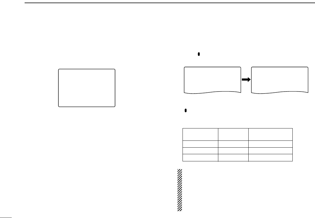
65
11 OTHER FUNCTIONS
• Playing speed setting
The playing speed can be selected from 5 speeds.
qPush [■
≈≈
]for 1 sec. to enter the playing speed set mode.
wRotate [R-DIAL] to select the desired speed, then push
[■
≈≈
].
DDRecording set mode
• Quality setting
qPush [ REC] for 1 sec. to enter the recording set mode.
wRotate [R-DIAL] to select “QUALITY,” then push [8 SET].
eRotate [R-DIAL] to select the recording quality, then push
[ REC].
rPush [DUALWATCH] momentarily to exit the recording set
mode.
NOTE:
The IC recorder can store 32 tracks at the maximum.
When the 32nd track is recorded, the recording function is
not available even recording time is left. At this time delete
all recorded contents (see the next page) or transfer the
recorded contents to PC using optional CS-R20
CLONING
SOFTWARE
.
*****-REC--*****
-REC-REMOTE
>QUALITY
-ALL-DELETE
----------------
QUALITY
-NORMAL
>LONG-TIME
-FINE
----------------
VOL
√
MODE ANL
AFCTSQL
FM
REC
145780
P S KIP
-DUP
√
MODE ANL
AFCTSQL
FM
REC
145780
P S KIP
-DUP
√
MODE ANL
AFCTSQL
FM
STOP
145780
P S KIP
-DUP
√
MODE ANL
AFCTSQL
FM
STOP
145780
P S KIP
-DUP
TRACK:06
TRACK:01
NORMAL
---------------
0:00:32/0:12:14
x1.00
---------------
VOL
TRACK:01
NORMAL
---------------
0:00:30/0:12:14
x1.00
---------------
81
VOL
TRACK:01
NORMAL
---------------
0:00:30/0:12:14
x1.00
---------------
81
√
MODE ANL
AFCTSQL
FM
145780
P S KIP
-DUP
PLAYBACK-SPEED
-x0.75
-x0.50
-x1.25
>x1.00
-x1.50
----------------
VOL
√
MODE ANL
AFCTSQL
FM
REC
145780
P S KIP
-DUP
√
MODE ANL
AFCTSQL
FM
REC
145780
P S KIP
-DUP
√
MODE ANL
AFCTSQL
FM
STOP
145780
P S KIP
-DUP
√
MODE ANL
AFCTSQL
FM
STOP
145780
P S KIP
-DUP
TRACK:06
TRACK:01
NORMAL
---------------
0:00:32/0:12:14
x1.00
---------------
VOL
TRACK:01
NORMAL
---------------
0:00:30/0:12:14
x1.00
---------------
81
VOL
TRACK:01
NORMAL
---------------
0:00:30/0:12:14
x1.00
---------------
81
√
MODE ANL
AFCTSQL
FM
145780
P S KIP
-DUP
Selection Recording Recording Time
Quality (Approx.)
LONG TIME Low 260 min.
NORMAL Normal 130 min.
FINE High 65 min.
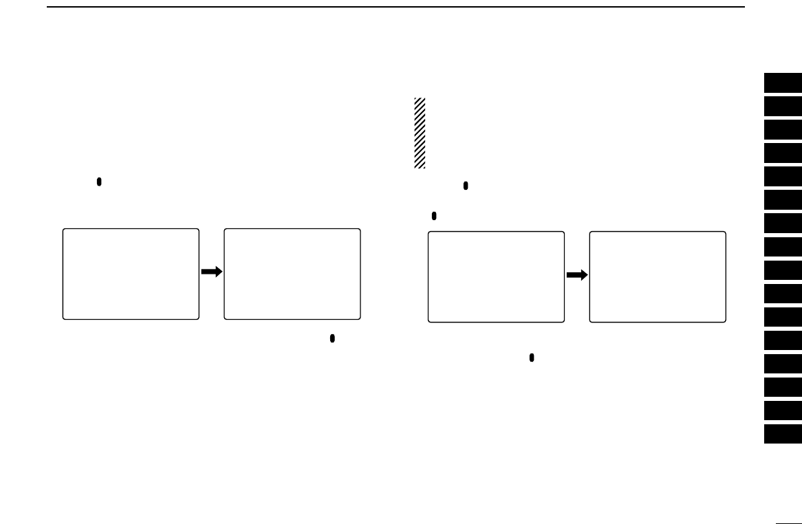
66
11
OTHER FUNCTIONS
1
2
3
4
5
6
7
8
9
10
11
12
13
14
15
16
• Automatic recording
The IC-R20 has an automatic recording function. When this
function is activated, the receiver will record automatically
when a receiving signal appears and pause when the signal
disappears. This function is very useful when you want to
store an uncontinuous signal.
qPush [ REC] for 1 sec. to enter the recording set mode.
wRotate [R-DIAL] to select “REC REMOTE” item, then push
[8 SET].
eRotate [R-DIAL] to select the setting, then push [ REC].
rPush [DUALWATCH] momentarily to exit the recording set
mode.
• Erasing recorded audio
NOTE:
The IC recorder can erase the all tracks at the same time,
but cannot erase each track independently. Only using the
optional CS-R20
CLONING SOFTWARE
can store the
recorded audio into a PC or erase independently.
qPush [ REC] for 1 sec. to enter the recording set mode.
wRotate [R-DIAL] to select “ALL DELETE” item, then push
[ REC].
eRotate [R-DIAL] to select “YES” if you want to delete all
tracks, then push [ REC].
• After deleting, the receiver returns to normal operating mode.
*****-REC--*****
-REC-REMOTE
-QUALITY
>ALL-DELETE
----------------
ALL-DELETE
>YES
-NO
----------------
VOL
√
MODE ANL
AFCTSQL
FM
REC
145780
P S KIP
-DUP
√
MODE ANL
AFCTSQL
FM
REC
145780
P S KIP
-DUP
√
MODE ANL
AFCTSQL
FM
STOP
145780
P S KIP
-DUP
√
MODE ANL
AFCTSQL
FM
STOP
145780
P S KIP
-DUP
TRACK:06
TRACK:01
NORMAL
---------------
0:00:32/0:12:14
x1.00
---------------
VOL
TRACK:01
NORMAL
---------------
0:00:30/0:12:14
x1.00
---------------
81
VOL
TRACK:01
NORMAL
---------------
0:00:30/0:12:14
x1.00
---------------
81
√
MODE ANL
AFCTSQL
FM
145780
P S KIP
-DUP
*****-REC--*****
>REC-REMOTE
-QUALITY
-ALL-DELETE
----------------
REC-REMOTE
>ON
-OFF
----------------
VOL
√
MODE ANL
AFCTSQL
FM
REC
145780
P S KIP
-DUP
√
MODE ANL
AFCTSQL
FM
REC
145780
P S KIP
-DUP
√
MODE ANL
AFCTSQL
FM
STOP
145780
P S KIP
-DUP
√
MODE ANL
AFCTSQL
FM
STOP
145780
P S KIP
-DUP
TRACK:06
TRACK:01
NORMAL
---------------
0:00:32/0:12:14
x1.00
---------------
VOL
TRACK:01
NORMAL
---------------
0:00:30/0:12:14
x1.00
---------------
81
VOL
TRACK:01
NORMAL
---------------
0:00:30/0:12:14
x1.00
---------------
81
√
MODE ANL
AFCTSQL
FM
145780
P S KIP
-DUP
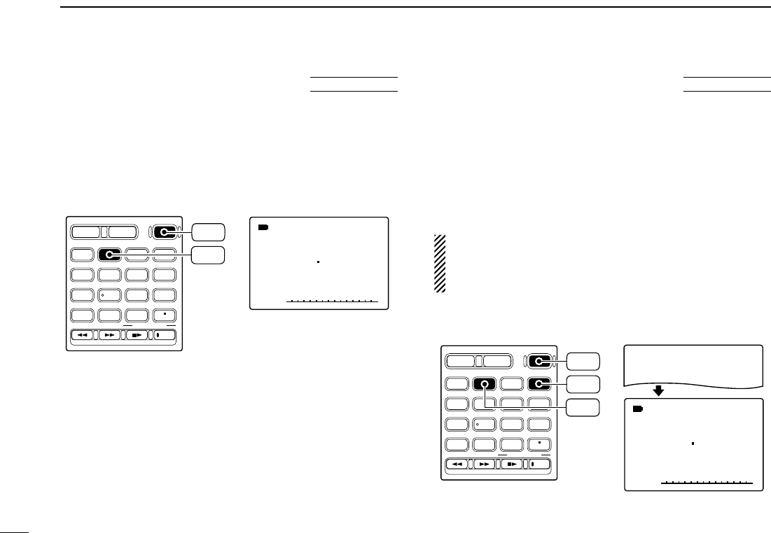
67
11 OTHER FUNCTIONS
■Partial reset
If you want to initialize the operating conditions (VFO fre-
quency, VFO settings, set mode contents) without clearing
the memory contents, a partial resetting function is available
for the receiver.
➥While pushing [VFO MHz], turn the power ON to partially
reset the receiver.
■All reset
The function display may occasionally display erroneous in-
formation (e.g. when first applying power). This may be
caused externally by static electricity or by other factors.
If this problem occurs, turn power OFF. After waiting a few
seconds, turn power ON again. If the problem persists, per-
form the following procedure.
• Partial resetting is also available. See left for details.
IMPORTANT!:
Resetting the receiver CLEARS all memory information
and initializes all values in the receiver, including TV chan-
nel skip setting.
➥While pushing [VFO MHz] and [MR S.MW], turn the power
ON to reset the CPU.
DIAL.SEL SWEEP CENTER
T-SCAN SKIP M.N
TONE SET TS
ATT RF GAIN
IC Recorder
123
4560
789
BAND
DUALWATCH
MAIN/SUB
POWER
VFO
MHz MODE
SCAN MR
S.MW
SCOPE
LOCK
REC
AFC
√
MODE ANL
AFCTSQL
FM
146010
PSKIP
-DUP
ALL-RESET
*The appearing frqeuency is
differ according to receiver
version.
VFO
MHz
MR
S.MW
POWER
AT
POWER ON
DIAL.SEL SWEEP CENTER
T-SCAN SKIP M.N
TONE SET TS
ATT RF GAIN
IC Recorder
123
4560
789
BAND
DUALWATCH
MAIN/SUB
POWER
VFO
MHz MODE
SCAN MR
S.MW
SCOPE
LOCK
REC
AFC
√
MODE ANL
AFCTSQL
FM
146010
PSKIP
-DUP
*The appearing frqeuency is
differ according to receiver
version.
VFO
MHz
POWER
AT
POWER ON

68
12
CONTROL COMMAND
1
2
3
4
5
6
7
8
9
10
11
12
13
14
15
16
■General
The IC-R20 can be connected to a PC via the PC’s RS-232C
port using an optional CT-17 CI-V LEVEL CONVERTOR. This
allows you to control the receiver from the PC and/or transfer
data from the receiver to the PC.
Control is provided via Icom’s CI-V Communication Interface.
■Data format
The CI-V system can be operated using the following data
formats. Data formats differ according to command numbers.
A data area is added for some commands.
Controller ➡IC-R20
IC-R20 ➡Controller
qPreamble code (fixed)
wReceiver’s default address
eController’s default address
rCommand number (see table below)
tSub command number (see table below)
yBCD code data for frequency entry
uEnd of message code (fixed)
■Command table
FE FE 6C E0 Cn Sc Data area FD
q wert y u
FE FE E0 6C Cn Sc Data area FD
q ewrt y u
Description Cn Sc
Transfers frequency data (transceive) 00 —
Transfers mode data (transceive) 01 —
Reads display frequency 03 —
Reads display mode 04 —
Sets frequency data 05 —
Sets LSB mode
06
00
Sets USB mode 01
Sets AM mode 02
Sets CW mode 03
Sets FM mode 05
Sets WFM mode 06
Reads squelch condition (open or closed) 15 01
Reads S-meter level 02
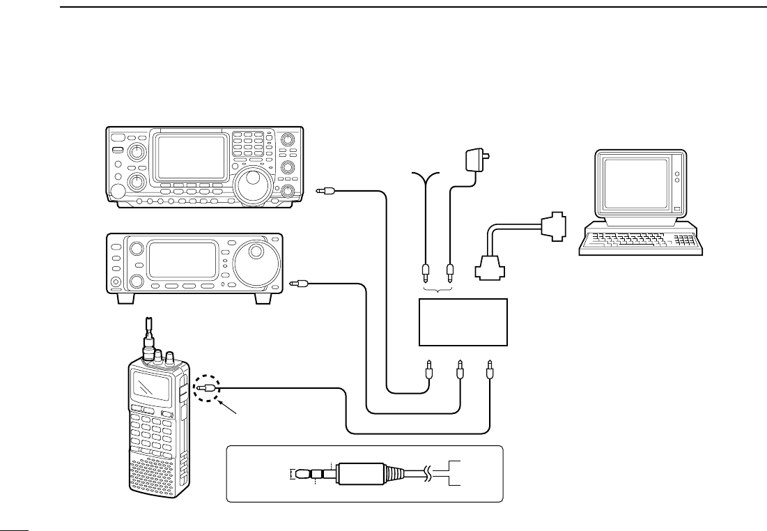
69
12 CONTROL COMMAND
CT-17
Power supply
9–15VDC
RS-232C
cable
IC-R20
to [SP/CI-V]
Computer
Optional
BC-25
CI-V connection example
3.5(d) mm
GND
I/O
GND
I/O
3.5(d) mm stereo plug
must be used.

70
13
FREQUENCY TABLE
CH Freq.
40 628.75
41 636.75
42 644.75
43 652.75
44 660.75
45 668.75
46 676.75
47 684.75
48 692.75
49 700.75
50 708.75
51 716.75
52 724.75
53 732.75
54 740.75
55 748.75
56 756.75
57 764.75
58 772.75
59 780.75
60 788.75
61 796.75
62 804.75
63 812.75
64 820.75
65 828.75
66 836.75
67 844.75
68 852.75
69 860.75
CH Freq.
1 46.75
2 53.75
3 60.75
4 67.75
5 180.75
6 187.75
7 194.75
8 201.75
9 208.75
10 215.75
11 222.75
12 229.75
21 476.75
22 484.75
23 492.75
24 500.75
25 508.75
26 516.75
27 524.75
28 532.75
29 540.75
30 548.75
31 556.75
32 564.75
33 572.75
34 580.75
35 588.75
36 596.75
37 604.75
38 612.75
39 620.75
■TV channels
The following tables show the channels versus
video and audio frequencies depending on each
version.
DDU.S.A. channels (unit: MHz)
CH Freq.
2 59.75
3 65.75
4 71.75
5 81.75
6 87.75
7 179.75
8 185.75
9 191.75
10 197.75
11 203.75
12 209.75
13 215.75
14 475.75
15 481.75
16 487.75
17 493.75
18 499.75
19 505.75
20 511.75
21 517.75
22 523.75
23 529.75
24 535.75
25 541.75
26 547.75
CH Freq.
27 553.75
28 559.75
29 565.75
30 571.75
31 577.75
32 583.75
33 589.75
34 595.75
35 601.75
36 607.75
37 613.75
38 619.75
39 625.75
40 631.75
41 637.75
42 643.75
43 649.75
44 655.75
45 661.75
46 667.75
47 673.75
48 679.75
49 685.75
50 691.75
51 697.75
CH Freq.
52 703.75
53 709.75
54 715.75
55 721.75
56 727.75
57 733.75
58 739.75
59 745.75
60 751.75
61 757.75
62 763.75
63 769.75
64 775.75
65 781.75
66 787.75
67 793.75
68 799.75
69 805.75
DDCCIR channels (unit: MHz) DDAustralian channels
(unit: MHz)
CH Freq.
43 637.75
44 644.75
45 651.75
46 658.75
47 665.75
48 672.75
49 679.75
50 686.75
51 693.75
52 700.75
53 707.75
54 714.75
55 721.75
56 728.75
57 735.75
58 742.75
59 749.75
60 756.75
61 763.75
62 770.75
63 777.75
64 784.75
65 791.75
66 798.75
67 805.75
68 812.75
69 819.75
CH Freq.
0 51.75
1 62.75
2 69.75
3 91.75
4 100.75
5 107.75
5A 143.75
6 180.75
7 187.75
8 194.75
9 201.75
10 214.75
11 221.75
28 532.75
29 539.75
30 546.75
31 553.75
32 560.75
33 567.75
34 574.75
35 581.75
36 588.75
37 595.75
38 602.75
39 609.75
40 616.75
41 623.75
42 630.75
1
2
3
4
5
6
7
8
9
10
11
12
13
14
15
16

71
13 FREQUENCY TABLE
DDChina channels (unit: MHz)
CH Freq.
1 56.25
2 64.25
3 72.25
4 83.75
5 91.75
6 174.75
7 182.75
8 190.75
9 198.75
10 206.75
11 214.75
12 222.75
13 477.75
14 485.75
15 493.75
16 501.75
17 509.75
18 517.75
19 525.75
20 533.75
21 541.75
22 549.75
23 557.75
24 565.75
25 613.75
26 621.75
27 629.75
28 637.75
29 645.75
30 653.75
31 661.75
CH Freq.
32 669.75
33 677.75
34 685.75
35 693.75
36 701.75
37 709.75
38 717.75
39 725.75
40 733.75
41 741.75
42 749.75
43 757.75
44 765.75
45 773.75
46 781.75
47 789.75
48 797.75
49 805.75
50 813.75
51 821.75
52 829.75
53 837.75
54 845.75
55 853.75
56 861.75
57 869.75
58 877.75
59 885.75
60 893.75
61 901.75
62 909.75
CH Freq.
63 917.75
64 925.75
65 933.75
66 941.75
67 949.75
68 957.75
CH Freq.
1 50.75
2 60.75
3 67.75
4 180.75
5 187.75
6 194.75
7 201.75
8 208.75
9 215.75
10 222.75
11 229.75
DDNew
Zealand
channels
(unit: MHz)
CH Freq.
52 725.25
53 733.25
54 741.25
55 749.25
56 757.25
57 765.25
58 773.25
59 781.25
60 789.25
61 797.25
62 805.25
63 813.25
64 821.25
65 829.25
66 837.25
67 845.25
68 853.25
69 861.25
CH Freq.
21 477.25
22 485.25
23 493.25
24 501.25
25 509.25
26 517.25
27 525.25
28 533.25
29 541.25
30 549.25
31 557.25
32 565.25
33 573.25
34 581.25
35 589.25
36 597.25
37 605.25
38 613.25
39 621.25
40 629.25
41 637.25
42 645.25
43 653.25
44 661.25
45 669.25
46 677.25
47 685.25
48 693.25
49 701.25
50 709.25
51 717.25
DDUK channels (unit: MHz)
CH Freq.
43 653.75
44 661.75
45 669.75
46 677.75
47 685.75
48 693.75
49 701.75
50 709.75
51 717.75
52 725.75
53 733.75
54 741.75
55 749.75
56 757.75
57 765.75
58 773.75
59 781.75
60 789.75
61 797.75
62 805.75
63 813.75
64 821.75
65 829.75
66 837.75
67 845.75
68 853.75
69 861.75
CH Freq.
2 49.25
3 54.00
4 57.25
5 182.50
6 190.50
7 198.50
8 206.50
9 214.50
10 222.50
21 477.75
22 485.75
23 493.75
24 501.75
25 509.75
26 517.75
27 525.75
28 533.75
29 541.75
30 549.75
31 557.75
32 565.75
33 573.75
34 581.75
35 589.75
36 597.75
37 605.75
38 613.75
39 621.75
40 629.75
41 637.75
42 645.75
DDFrench channels (unit: MHz)

72
13
FREQUENCY TABLE
DDIndonesian channels
(unit: MHz)
CH Freq.
2 53.75
3 60.75
4 67.75
5 180.75
6 187.75
7 194.75
8 201.75
9 208.75
10 215.75
11 222.75
12 229.75
21 476.75
22 484.75
23 492.75
24 500.75
25 508.75
26 516.75
27 524.75
28 532.75
29 540.75
30 548.75
31 556.75
32 564.75
33 572.75
34 580.75
35 588.75
36 596.75
37 604.75
38 612.75
39 620.75
CH Freq.
40 628.75
41 636.75
42 644.75
43 652.75
44 660.75
45 668.75
46 676.75
47 684.75
48 692.75
49 700.75
50 708.75
51 716.75
52 724.75
53 732.75
54 740.75
55 748.75
56 756.75
57 764.75
58 772.75
59 780.75
60 788.75
61 796.75
62 804.75
63 812.75
64 820.75
65 828.75
66 836.75
67 844.75
68 852.75
69 860.75
DDItalian channels (unit: MHz)
CH Freq.
A 59.25
B 67.75
C 87.75
D 180.75
E 188.75
F 197.75
G 206.75
H 215.75
H1 222.75
H2 229.75
21 476.75
22 484.75
23 492.75
24 500.75
25 508.75
26 516.75
27 524.75
28 532.75
29 540.75
30 548.75
31 556.75
32 564.75
33 572.75
34 580.75
35 588.75
36 596.75
37 604.75
38 612.75
39 620.75
40 628.75
41 636.75
CH Freq.
42 644.75
43 652.75
44 660.75
45 668.75
46 676.75
47 684.75
48 692.75
49 700.75
50 708.75
51 716.75
52 724.75
53 732.75
54 740.75
55 748.75
56 756.75
57 764.75
58 772.75
59 780.75
60 788.75
61 796.75
62 804.75
63 812.75
64 820.75
65 828.75
66 836.75
67 844.75
68 852.75
69 860.75
DDTaiwan channels
(unit: MHz)
CH Freq.
7 179.75
8 185.75
9 191.75
10 197.75
11 203.75
12 209.75
DDFOT channels
(unit: MHz)
CH Freq.
4 181.75
5 189.75
6 197.75
7 205.75
8 213.75
9 221.75
1
2
3
4
5
6
7
8
9
10
11
12
13
14
15
16

73
13 FREQUENCY TABLE
■VHF marine channels (unit: MHz)
CH Ship Ship
No. Transmit Receive
01 156.050 160.650
01A 156.050 156.050
02 156.100 160.700
03 156.150 160.750
03A 156.150 156.150
04 156.200 160.800
04A 156.200 156.200
05 156.250 160.850
05A 156.250 156.250
06 156.300 156.300
07 156.350 160.950
07A 156.350 156.350
08 156.400 156.400
09 156.450 156.450
10 156.500 156.500
11 156.550 156.550
12 156.600 156.600
13 156.650 156.650
14 156.700 156.700
15 156.750 156.750
16 156.800 156.800
17 156.850 156.850
18 156.900 161.500
18A 156.900 156.900
19 156.950 161.550
19A 156.950 156.950
20 157.000 161.600
20A 157.000 157.000
21 157.050 161.650
WX CH Frequency
01 162.550
02 162.400
03 162.475
04 162.425
05 162.450
06 162.500
07 162.525
08 161.650
09 161.775
10 163.275
CH Ship Ship
No. Transmit Receive
21A 157.050 157.050
21b 161.650 161.650
22 157.100 161.700
22A 157.100 157.100
23 157.150 161.750
23A 157.150 157.150
24 157.200 161.800
25 157.250 161.850
25b 161.850 161.850
26 157.300 161.900
27 157.350 161.950
28 157.400 162.000
28b 162.000 162.000
60 156.025 160.625
61 156.075 160.675
61A 156.075 156.075
62 156.125 160.725
62A 156.125 156.125
63 156.175 160.775
63A 156.175 156.175
64 156.225 160.825
64A 156.225 156.225
65 156.275 160.875
65A 156.275 156.275
66 156.325 160.925
66A 156.325 156.325
67 156.375 156.375
68 156.425 156.425
69 156.475 156.475
CH Ship Ship
No. Transmit Receive
70 156.525 156.525
71 156.575 156.575
72 156.625 156.625
73 156.675 156.675
74 156.725 156.725
77 156.875 156.875
78 156.925 161.525
78A 156.925 156.925
79 156.975 161.575
79A 156.975 156.975
80 157.025 161.625
80A 157.025 157.025
81 157.075 161.675
81A 157.075 157.075
82 157.125 161.725
82A 157.125 157.125
83 157.175 161.775
83A 157.175 157.175
83b 161.775 161.775
84 157.225 161.825
84A 157.225 157.225
85 157.275 161.875
85A 157.275 157.275
86 157.325 161.925
86A 157.325 157.325
87 157.375 161.975
87A 157.375 157.375
88 157.425 162.025
88A 157.425 157.425
■Weather channels(unit: MHz)

74
13
FREQUENCY TABLE
CH Frequency
1 462.5625 MHz
2 462.5875 MHz
3 462.6125 MHz
4 462.6375 MHz
5 462.6625 MHz
6 462.6875 MHz
7 462.7125 MHz
■Other communications in the USA
DDFRS (Family Radio Service) channels
Dot color Frequency
Red 151.625 MHz
Purple 151.955 MHz
Blue 154.570 MHz
Green 154.600 MHz
White 462.575 MHz
Black 462.625 MHz
Orange 462.675 MHz
Brown 464.500 MHz
Yellow 464.550 MHz
“J” Dot 467.763 MHz
“K” Dot 467.813 MHz
Silver Star 467.850 MHz
Gold Star 467.875 MHz
Red Star 467.900 MHz
Blue Star 467.925 MHz
Transceiver Transceiver
Receive transmit
462.5500 MHz 467.5500 MHz
462.5625 MHz
462.5750 MHz 467.5750 MHz
462.5875 MHz
462.6000 MHz 467.6000 MHz
462.6125 MHz
462.6250 MHz 467.6250 MHz
462.6375 MHz
462.6500 MHz 467.6500 MHz
462.6625 MHz
462.6750 MHz 467.6750 MHz
462.6875 MHz
462.7000 MHz 467.7000 MHz
462.7125 MHz
462.7250 MHz 467.7250 MHz
CH Frequency
1 151.820 MHz
2 151.880 MHz
3 151.940 MHz
4 154.570 MHz
5 154.600 MHz
CH Frequency
1 26.965 MHz
2 26.975 MHz
3 26.985 MHz
4 27.005 MHz
5 27.015 MHz
6 27.025 MHz
7 27.035 MHz
8 27.055 MHz
9 27.065 MHz
10 27.075 MHz
11 27.085 MHz
12 27.105 MHz
13 27.115 MHz
14 27.125 MHz
15 27.135 MHz
16 27.155 MHz
17 27.165 MHz
18 27.175 MHz
19 27.185 MHz
20 27.205 MHz
DDBRS (Business Radio
Service) channels
DDGMRS (General Mobile
Radio Service) channels
DDMURS channels
DDHF CB (Citizens Band) channels
CH Frequency
21 27.215 MHz
22 27.225 MHz
23 27.255 MHz
24 27.235 MHz
25 27.245 MHz
26 27.265 MHz
27 27.275 MHz
28 27.285 MHz
29 27.295 MHz
30 27.305 MHz
31 27.315 MHz
32 27.325 MHz
33 27.335 MHz
34 27.345 MHz
35 27.355 MHz
36 27.365 MHz
37 27.375 MHz
38 27.385 MHz
39 27.395 MHz
40 27.405 MHz
CH Frequency
8 467.5625 MHz
9 467.5875 MHz
10 467.6125 MHz
11 467.6375 MHz
12 467.6625 MHz
13 467.6875 MHz
14 467.7125 MHz
1
2
3
4
5
6
7
8
9
10
11
12
13
14
15
16

75
13 FREQUENCY TABLE
Frequency Description
121.500 Emergencies
122.000 Flight Advisory Service
122.200 Flight Service Stations
122.700 Unicom— Uncontrolled airports
122.725 Unicom— Private airports
122.750 Unicom— Air-to-air communications
122.800 Unicom— Uncontrolled airports
122.900 Search & rescue training, & uncontrolled airports
122.950 Unicom— Controlled airports
123.000 Unicom— Uncontrolled airports
123.025 Helicopters— Air-to-air communications
123.050 Unicom— Heliports
123.075 Unicom— Heliports
123.100 Search & Rescue
123.300 Flight Schools
123.450 Air-to-air communications (unofficial)
123.500 Flight Schools
123.600 Flight Service Stations— Uncontrolled airports
148.125 Civil Air Patrol Repeaters— Secondary
148.150 Civil Air Patrol Repeaters— Primary
156.300 Aircraft-to-ship— safety
156.400 Aircraft-to-ship— commercial
156.425 Aircraft-to-ship— non-commercial
156.450 Aircraft-to-ship— commercial
156.625 Aircraft-to-ship— non-commercial
156.900 Aircraft-to-ship— commercial
243.000 Military Emergency “Guard”
255.400 Flight Advisory Service
257.800 Civilian Towers
311.000 SAC Primary
321.000 SAC Secondary
381.800 USCG— Primary
DDGeneral aviation frequencies
CH
Frequency
Remarks
range
2– 13 54–216 (same as broadcast VHF)
14– 22 120–174 Mid band Ch. A–I
23– 36 216–300 Super band J–W
37– 53 300–402 Hyper band AA–QQ
54– 64 402–468
65– 94 468–648 (Ultra band)
95– 99 90–120 Low band A5–A1
100–125 648–804 (Ultra band)
DDCable TV (IRC) (unit: MHz)
169.445 MHz
169.505 MHz
170.245 MHz
170.305 MHz
171.045 MHz
171.105 MHz
171.845 MHz
171.905 MHz
*Power limited to 1/20 watt. These frequencies are also used at drive-in win-
dows at some fast-food restaurants.
DDWireless Microphones

76
13
FREQUENCY TABLE
■Other communications— other countries
CH Frequency
1 446.00625
2 446.01875
3 446.03125
4 446.04375
5 446.05625
6 446.06875
7 446.08125
8 446.09375
DD
PMR446 channels
(unit: MHz)
CH Frequency
59 434.525
60 434.550
61 434.575
62 434.600
63 434.625
64 434.650
65 434.675
66 434.700
67 434.725
68 434.750
69 434.775
CH Frequency
1 433.075
2 433.100
3 433.125
4 433.150
5 433.175
6 433.200
7 433.225
8 433.250
9 433.275
10 433.300
11 433.325
12 433.350
13 433.375
14 433.400
15 433.425
16 433.450
17 433.475
18 433.500
19 433.525
20 433.550
21 433.575
22 433.600
23 433.625
24 433.650
25 433.675
26 433.700
27 433.725
28 433.750
29 433.775
DDLPD (Low Power Device) channels (unit: MHz)
CH Frequency
30 433.800
31 433.825
32 433.850
33 433.875
34 433.900
35 433.925
36 433.950
37 433.975
38 434.000
39 434.025
40 434.050
41 434.075
42 434.100
43 434.125
44 434.150
45 434.175
46 434.200
47 434.225
48 434.250
49 434.275
50 434.300
51 434.325
52 434.350
53 434.375
54 434.400
55 434.425
56 434.450
57 434.475
58 434.500
1
2
3
4
5
6
7
8
9
10
11
12
13
14
15
16

77
13 FREQUENCY TABLE
CH Frequency
1 476.425 MHz
2 476.450 MHz
3 476.475 MHz
4 476.500 MHz
5 476.525 MHz
6 476.550 MHz
7 476.575 MHz
8 476.600 MHz
9 476.625 MHz
10 476.650 MHz
11 476.675 MHz
12 476.700 MHz
13 476.725 MHz
14 476.750 MHz
15 476.775 MHz
16 476.800 MHz
17 476.825 MHz
18 476.850 MHz
19 476.875 MHz
20 476.900 MHz
DDUHF C.R.S (Citizen Radio Service) channels
CH Frequency
21 476.925 MHz
22 476.950 MHz
23 476.975 MHz
24 477.000 MHz
25 477.025 MHz
26 477.050 MHz
27 477.075 MHz
28 477.100 MHz
29 477.125 MHz
30 477.150 MHz
31 477.175 MHz
32 477.200 MHz
33 477.225 MHz
34 477.250 MHz
35 477.275 MHz
36 477.300 MHz
37 477.325 MHz
38 477.350 MHz
39 477.375 MHz
40 477.400 MHz

78
14
MAINTENANCE
PROBLEM POSSIBLE CAUSE SOLUTION REF.
■Troubleshooting If your receiver seems to be malfunctioning, please check the
following points before sending it to a service center.
No power comes on.
No sound comes from the
speaker.
Sensitivity is low and only
strong signals are audible.
Frequency cannot be set.
No beep sound.
Receive audio is distorted.
Desired set mode item
cannot be selected.
Programmed scan does
not start.
Memory or bank scan
does not start.
• The batteries are exhausted.
• The battery polarity is reversed.
• Volume level is too low.
• Squelch level is set too tight.
• Different tone is selected with tone squelch.
• Attenuator function is activated.
• RF gain setting is too low for SSB/CW modes.
• The lock function is activated.
• Beep tones are turned OFF or the beep tone level
is too low.
• The operating mode is not selected correctly.
• “EXPAND” item is set to OFF.
• Program scan edges are not programmed.
• No or only one memory or bank channel is pro-
grammed.
• Replace the batteries or charge the battery pack.
• Check the battery polarity.
• Rotate [R-DIAL] or push [Y] to obtain a suitable level.
• While pushing [SQL], rotate [R-DIAL] to set the
squelch level.
• Turn the appropriate function OFF.
• Push [ATT] for 1 sec. to turn the attenuator function
OFF.
• Push [RF GAIN] for 1 sec., then rotate [R-DIAL] to
select “MAX” level.
• Push [• LOCK] for 1 sec. to turn the function OFF.
• Turn beep tone ON or set the beep tone level to ap-
propriate level in set mode.
• Push [MODE•SCAN] several times to select a suit-
able operating mode.
• Turn “EXPAND” item ON.
• Program a pair of scan edge channels.
• Program at least 2 memory or bank channels
pgs. 8–10
p. 8
p. 17
p. 18
p. 45
p. 19
p. 19
p. 16
p. 51
p. 16
p. 49
p. 36
pgs. 26,
27
1
2
3
4
5
6
7
8
9
10
11
12
13
14
15
16

79
SPECIFICATIONS
15
DDGENERAL
• Frequency coverage : (Unit: MHz)
USA 0.150–821.999, 851.000–866.999,
896.000–1304.999, 1305.000–3304.999
France 0.150–29.999, 50.200–51.200,
87.500–108.000, 144.000–146.000,
430.000–440.000, 1240.000–1300.000
Other than above 0.150–1304.999, 1305.000–3304.999
• Number of memory channels : 1250 (incl. 50 scan edges and 200 auto
write channels)
• Frequency resolution : 0.01, 0.1, 1, 5, 6.25, 8.33,* 9*, 10, 12.5,
15, 20, 25, 30, 50, 100 kHz
*selectable depending on the operating frequency band.
• Operating temperature range : –10°C to +60°C; +14˚F to +140˚F
• Reference frequency stability : ±6 ppm (–10°C to +60°C; +14˚F to +140˚F)
• Power supply requirement : 3 AA (R6) alkaline cells,
(Negative ground) BP-206 Li-ion battery pack or
6.0 V DC ±5%
(with AC adaptor, BC-149A/D or CP-18A/E)
• Current drain :
(Receiving on single mode with not recording at 3.7 V DC)
standby (power saved) approx. 35 mA typical
stand receive approx. 100 mA typical
max. audio approx. 150 mA typical
• Antenna connector : BNC (50 Ω)
• Dimensions (proj. not included) : 60(W) ×142(H) ×34.8(D) mm
23⁄8(W)×519⁄32(H)×13⁄8(D) in
• Weight (approx.) : 320 g; 11.3 oz (with the ant. and BP-206)
•
AF output power
(at 3.7 V DC)
: 100 mW typical at 10% distortion with an
8 Ωload
• Ext. speaker connector : 3-conductor 3.5 (d) mm (1⁄8″)/8 Ω
DDRECEIVER
• Receive system : Triple-conversion superheterodyne and
down converter
• Intermediate frequencies : 1st: 266.7 MHz and 429.1 MHz,
2nd: 19.65 MHz, 3rd: 450 kHz
• Sensitivity (Receiving on single mode, except spurious points) :
FM (1 kHz/3.5 kHz Dev.; 12 dB SINAD)
1.620–4.999 MHz Less than 0.56 µV
5.000–221.999 MHz Less than 0.4 µV
330.000–832.999 MHz Less than 0.56 µV
833.000–1304.999 MHz Less than 0.71 µV
1330.000–2304.999 MHz Less than 5.6 µV
2330.000–2999.999 MHz Less than 18 µV
WFM (1 kHz/52.5 kHz Dev.; 12 dB SINAD)
76.000–108.000 MHz Less than 1.8 µV
175.000–221.999 MHz Less than 1.8 µV
470.000–769.999 MHz Less than 2.5 µV
AM (1 kHz/30% MOD.; 10 dB S/N)
0.495–4.999 MHz Less than 2.2 µV
5.000–29.999 MHz Less than 1.4 µV
118.000–135.999 MHz Less than 1.4 µV
SSB/CW (1 kHz/30% MOD.; 10 dB S/N)
0.495–4.999 MHz Less than 0.4 µV
5.000–29.999 MHz Less than 0.25 µV
50.000–53.999 MHz Less than 0.25 µV
118.000–146.999 MHz Less than 0.25 µV
330.000–469.999 MHz Less than 0.32 µV
• Selectivity :
AM/FM More than 12 kHz/–6 dB
Less than 30 kHz/–60 dB
WFM More than 150 kHz/–6 dB
SSB/CW More than 1.8 kHz/–6 dB
All stated specifications are subject to change without notice or obligation.
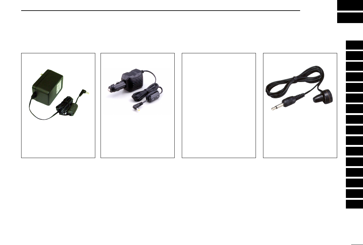
80
16
OPTIONS
1
2
3
4
5
6
7
8
9
10
11
12
13
14
15
16
■Options
BC-149 A/D
AC ADAPTOR
Regularly charges the installed
batteries.
6 V DC/1 A output.
CP-18A/E
CIGARETTE LIGHTER
CABLE WITH DC
-
DC CONVERTER
Allows you to operate the re-
ceiver through a 12 V cigarette
lighter socket, and also charges
the installed rechargeable bat-
teries regularly. A DC-DC con-
verter is built-in.
BC-156
DESKTOP CHARGER
Used for rapid charging of Li-
Ion battery pack. Charging
time: 2.5 hours. An AC adapter
is supplied with the charger.
SP-13
EARPHONE
Provides clear receive audio in
noisy environments.
LC-158
CARRYING CASE
Helps protect the receiver from
scratches, etc.
CT-17
CI
-
V LEVEL CONVERTOR
For receiver remote control using
a PC.
CS-R20
CLONING SOFTWARE
+ OPC-1382
CLONING CABLE
(USB type)
Allows you to transfer data, such
as memories, and quickly and
easily edit and store data via a
PC (for Microsoft®Windows®
98/Me/2000/XP). Also available to
transfer recorded audio and store
into PC.
MB-86
SWIVEL BELT CLIP
Swivel belt clip is useful for easy
attaching/detaching the receiver
to/from the belt.

1-1-32 Kamiminami, Hirano-ku, Osaka 547-0003, Japan
A-6353H-1EX
Printed in Japan
©2004 Icom Inc.