ICOM orporated 271400 Marine Radar User Manual MXR 5000R MXR 5000T Instruction Manual
ICOM Incorporated Marine Radar MXR 5000R MXR 5000T Instruction Manual
Contents
- 1. Manual
- 2. User Manual
User Manual

INSTRUCTION MANUAL
MARINE RADAR
MXR-5000R
(Radome type)
MXR-5000T
(Open array type)
This device complies with Part 15 of the FCC Rules. Op-
eration is subject to the condition that this device does
not cause harmful interference.
MXR-5000T / Page 13-1-1

ii
FOREWORD
Thank you for purchasing Icom’s MXR-5000R/T m a -
r i n e r a d a r .
The radar is designed for use with the
Icom Marine-
Commander™
system through the supplied connection
cable.
It has powerful transmission power, and many other
advanced features can be used with the
Icom Marine-
Commander™
system.
IMPORTANT
READ THIS INSTRUCTION MANUAL
CAREFULLY before attempting to operate the
radar.
SAVE THIS INSTRUCTION MANUAL. This
manual contains important safety and operating
instructions for the MXR-5000R/T.
SYSTEM COMPONENTS
MODEL NAME UNIT SCANNER UNIT
MXR-5000R
(Radar) Radar unit EX-2714
(Radome type)
MXR-5000T
(Radar) Radar unit EX-2780
(Open array type)
EXPLICIT DEFINITIONS
WORD DEFINITION
RDANGER Personal death, serious injury or an explo-
sion may occur.
RWARNING Personal injury, fire hazard or electric
shock may occur.
CAUTION Equipment damage may occur.
NOTE
If disregarded, inconvenience only. No risk
of personal injury, fire or electric shock.
The MXR-5000R/T are supplemental aids to navi-
gation and are not intended to be a substitute for
accurate and current nautical charts.
SUPPLIED ACCESSORIES
Qty.
• DC power cable .......................................................... 1
• Connection cable ........................................................ 1
• Spring washers (M5) .................................................. 8
• Flat washers (M5) ...................................................... 8
• Nuts (M5) ................................................................... 4
• Bolts (M5×30 mm) ...................................................... 4
• Fuse (FGB 5 A for 24 V power source) ...................... 1
• Spare fuse (FGB 10 A for 12 V power source) ........... 1
• Scanner unit ......................................................... 1 set
EX-2714 (Radome type) for MXR-5000R
- System cable (OPC-1188A: 15 m) ........................... 1
- Bolts (M10×50 mm) .................................................. 4
- Bolts (M10×25 mm) .................................................. 4
- Nuts (M10) ............................................................... 4
- Flat washers (M10) .................................................. 4
- Spring washers (M10) .............................................. 4
EX-2780 (Open array type) for MXR-5000T
- System cable (OPC-1189A: 20 m) ............................ 1
- Bolts (M10×40 mm) .................................................. 4
- Nuts (M10) ............................................................... 4
- Flat washers (M10) .................................................. 4
- Spring washers (M10) .............................................. 4
- Allen wrench ............................................................. 1
- Cap bolts (M8×18 mm) ............................................. 4
- Belleville washers (M8) ............................................ 4
- Sealing washers (T) ................................................. 4
- Flat washers (M8) .................................................... 4
- Grounding terminal (R5.5-10) .................................. 1
- Ferrite bead .............................................................. 1
FCC INFORMATION
• FOR CLASS A UNINTENTIONAL RADIATORS:
This equipment has been tested and found to comply
with the limits for a Class A digital device, pursuant to
part 15 of the FCC Rules. These limits are designed
to provide reasonable protection against harmful
interference when the equipment is operated in a
commercial environment. This equipment generates,
uses, and can radiate radio frequency energy and, if
not installed and used in accordance with the instruc-
tion manual, may cause harmful interference to radio
communications. Operation of this equipment in a
residential area is likely to cause harmful interference
in which case the user will be required to correct the
interference at his own expense.
Icom, Icom Inc. and the Icom logo are registered trademarks of
Icom Incorporated (Japan) in Japan, the United States, the United
Kingdom, Germany, France, Spain, Russia and/or other countries.
MarineCommander is a trademark of Icom Incorporated.
All other products or brands are registered trademarks or trade-
marks of their respective holders.
MXR-5000T / Page 13-1-2

ii
For radar unit:
R
WARNING! NEVER let metal, wire or other
objects touch any internal part or terminals of the radar
unit. This may result in an electric shock.
R
WARNING! NEVER apply AC voltage to the
DC input terminals of the radar unit. This may pose a
fire hazard, result in an electric shock or damage the
radar unit.
R
WARNING! NEVER apply more than 32 V DC
to the DC input terminal of the radar unit. This may
pose a fire hazard or damage the radar unit.
R
WARNING! NEVER touch the radar unit with
wet hands. This may result in an electric shock or dam-
age the radar unit.
R
WARNING! NEVER open the bottom cover of
the radar unit. There are no user adjustment points.
This may result in an electric shock and incorrect reas-
sembly may cause a fire hazard.
CAUTION! NEVER connect the radar unit to a DC
power source using reverse polarity. This will damage
the radar unit.
CAUTION! NEVER remove the fuse holder from
the DC power cable. This will damage the radar unit.
DO NOT place the radar unit in excessively dusty
environments.
DO NOT place the radar unit near heating equip-
ment or in direct sunlight or where hot or cold air blows
directly onto it.
DO NOT use or place the radar unit in areas with tem-
perature below –20˚C (–4˚F) or above +60˚C (+140˚F).
DO NOT use chemical agents such as benzine or
alcohol when cleaning the radar unit, as they can
damage the radar unit’s surfaces.
DO NOT place the radar unit in areas that will block
air passage or put anything around the radar unit. This
will obstruct heat dissipation.
KEEP the radar unit out of the reach of children.
KEEP the radar unit away from heavy rain, and never
immerse it in the water.
The radar unit meets IPX4 requirements for splash re-
sistance when the supplied connection cable, scanner
unit are connected.
However, if it is dropped, splash resistance cannot be
guaranteed because of possible damage to the case
or the waterproof seals.
For Scanner unit:
R
DANGER: HIGH VOLTAGE! NEVER open
the scanner unit. The scanner unit contains high volt-
age that could be fatal. And there are no user adjust-
ment points. All repairs and adjustments MUST be
made by a qualified electronics technician at your
Marine Navigation Dealer.
For qualified electronics technician only:
R
DANGER: HIGH VOLTAGE! High volt-
ages of up to 3,500 volts are used in the scanner
unit. Although prudent measures for safety have
been adopted, sufficient care must be taken in
the operation, maintenance and adjustment of the
scanner unit.
Electric shock of 1,000 volts or more may cause
electrocution and death; even an electric shock of
only 100 volts may be fatal.
R DANGER: HIGH VOLTAGE! To prevent an
electric shock, turn the radar’s power is OFF*1 and
do not reach inside the scanner unit until you have:
• discharged the capacitors by disconnecting the system
cable from the radar unit for 5 min.
• checked that no electric charges remain inside the de-
vice.
Also, it is safest to wear dry insulated rubber gloves.
NEVER use both hands simultaneously; keep one
hand in your pocket.
R
WARNING: RADIATION HAZARD!
Radiation emitted from the scanner unit can be
harmful, particularly to the eyes. To avoid harm-
ful radiation, turn
the radar’s power is OFF*1
before
beginning work on the scanner unit.
DO NOT use or place the scanner unit in areas with
temperature below –25˚C (–13˚F) or above +70˚C
(+158˚F).
NEVER immerse the scanner unit in the water.
The scanner units meet IPX6
*2
requirements for high-
pressure water jet resistance.
However, if these items are dropped, high-pressure
water jet resistance cannot be guaranteed because
of possible damage to the cases or the waterproof
seals.
*1
The radar’s power automatically turns OFF approx. 30 sec.
after the display units’ power are turned OFF.
*2
Except for the cable connectors. They meet IPX4 require-
ments while connecting to the radar unit.
For U.S.A. only
CAUTION: Changes or modifications to this radar,
not expressly approved by Icom Inc., could void your
authority to operate this device under FCC regulations.
PRECAUTIONS
MXR-5000T / Page 13-1-3

iii
RADAR OPERATOR WARNING
TABLE OF CONTENTS
FOREWORD .............................................................. i
IMPORTANT ............................................................... i
SYSTEM COMPONENTS .......................................... i
EXPLICIT DEFINITIONS ............................................ i
SUPPLIED ACCESSORIES....................................... i
FCC INFORMATION .................................................. i
PRECAUTIONS ......................................................... ii
RADAR OPERATOR WARNING .............................. iii
TABLE OF CONTENTS ........................................... iii
1 PANEL DESCRIPTION......................................... 1
■ MXR-5000 (Radar unit) ..................................... 1
2 INSTALLATION AND CONNECTIONS ............ 2–7
■ Connection ........................................................ 2
■ Power source requirement ................................ 2
■ Ground connection ............................................ 2
■ Mounting ........................................................... 2
■ Mounting the EX-2714 scanner unit .................. 3
■ Wiring the EX-2714 system cable ..................... 4
■ Mounting the EX-2780 scanner unit .................. 5
■ Wiring the EX-2780 system cable ..................... 6
■ Attaching the EX-2780 scanner unit .................. 7
3 MAINTENANCE AND OPTIONS ......................... 8
■ Periodic maintenance ........................................ 8
■ Scanner unit maintenance ................................ 8
■ Fuse replacement ............................................. 8
■ Options .............................................................. 8
4 SPECIFICATIONS ................................................ 9
WARNING
Icom requires the radar operator to meet
the FCC Requirements for Radio
Frequency Exposure. A slotted wave-
guide array antenna with gain not greater
than 27 dBi must be mounted a minimum
of 5.5 meters (measured from the lowest point of the
antenna) vertically above the main deck and all possi-
ble personnel. This is the minimum safe separation
distance estimated to meet all RF exposure compli-
ance requirements. This 5.5 meter distance is based
on the FCC Safe Maximum Permissible Exposure
(MPE) distance of 3.5 meters added to the height of
an adult (2 meters) and is appropriate for all vessels.
For watercraft without suitable structures, the antenna
must be mounted so as to maintain a minimum of
1 meter vertically between the antenna, (measured
from the lowest point of the antenna), to the heads of
all persons AND all persons must stay outside of the
3.5 meter MPE radius.
Do not transmit with radar and antenna when persons
are within the MPE radius of the antenna, unless
such persons (such as driver or radar operator) are
shielded from antenna field by a grounded metal-
lic barrier. The MPE Radius is the minimum distance
from the antenna axis that person should maintain in
order to avoid RF exposure higher than the allowable
MPE level set by FCC.
FAILURE TO OBSERVE THESE LIMITS MAY
ALLOW THOSE WITHIN THE MPE RADIUS TO
EXPERIENCE RF RADIATION ABSORPTION
W H I C H E X C E E D S T H E F C C M A X I M U M
PERMISSIBLE EXPOSURE (MPE) LIMIT.
IT IS THE RESPONSIBILITY OF THE RADAR
OPERATOR TO ENSURE THAT THE MAXIMUM
PERMISSIBLE EXPOSURE LIMITS ARE
OBSERVED AT ALL TIMES DURING RADAR
TRANSMISSION. THE RADAR OPERATOR IS TO
ENSURE THAT NO BYSTANDERS COME WITHIN
THE RADIUS OF THE MAXIMUM PERMISSIBLE
EXPOSURE LIMITS.
Determining MPE Radius
THE MAXIMUM PERMISSIBLE EXPOSURE (MPE)
RADIUS HAS BEEN ESTIMATED TO BE A RADIUS
OF ABOUT 3.5 M PER OET BULLETIN 65 OF THE
FCC.
THIS ESTIMATE IS MADE ASSUMING THE
MAXIMUM POWER OF THE RADAR AND
ANTENNAS WITH A MAXIMUM GAIN OF 27 dBi
ARE USED FOR A SHIP MOUNTED SYSTEM.
MXR-5000T / Page 13-1-4

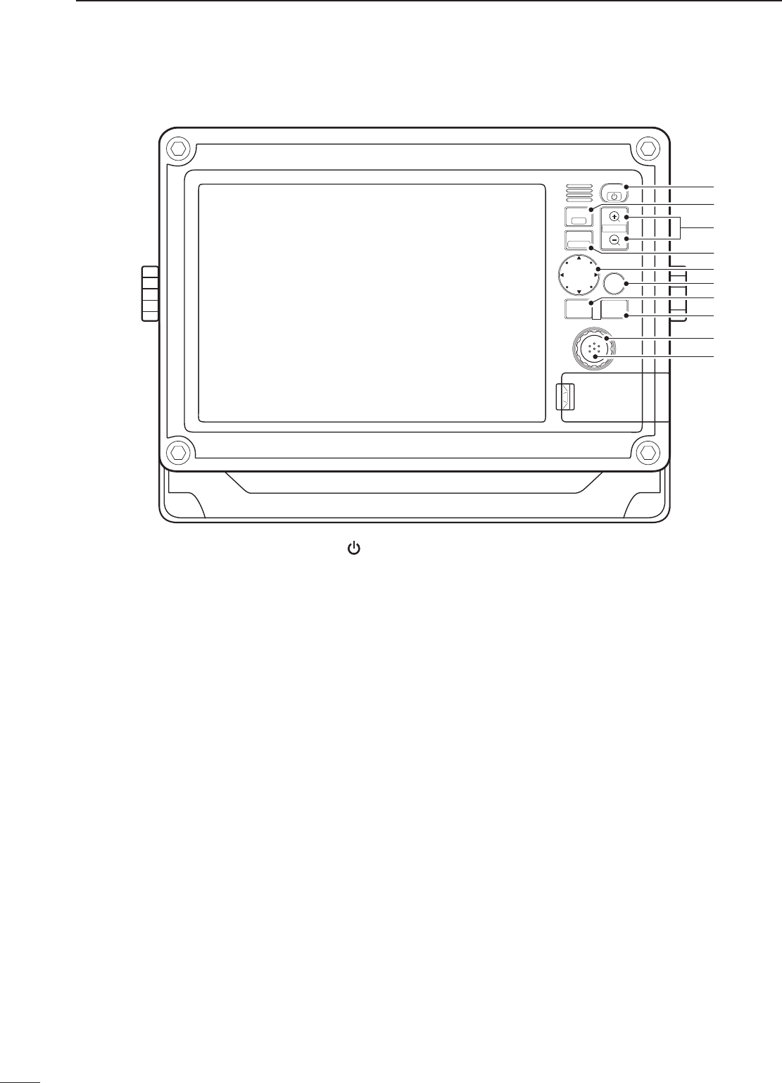
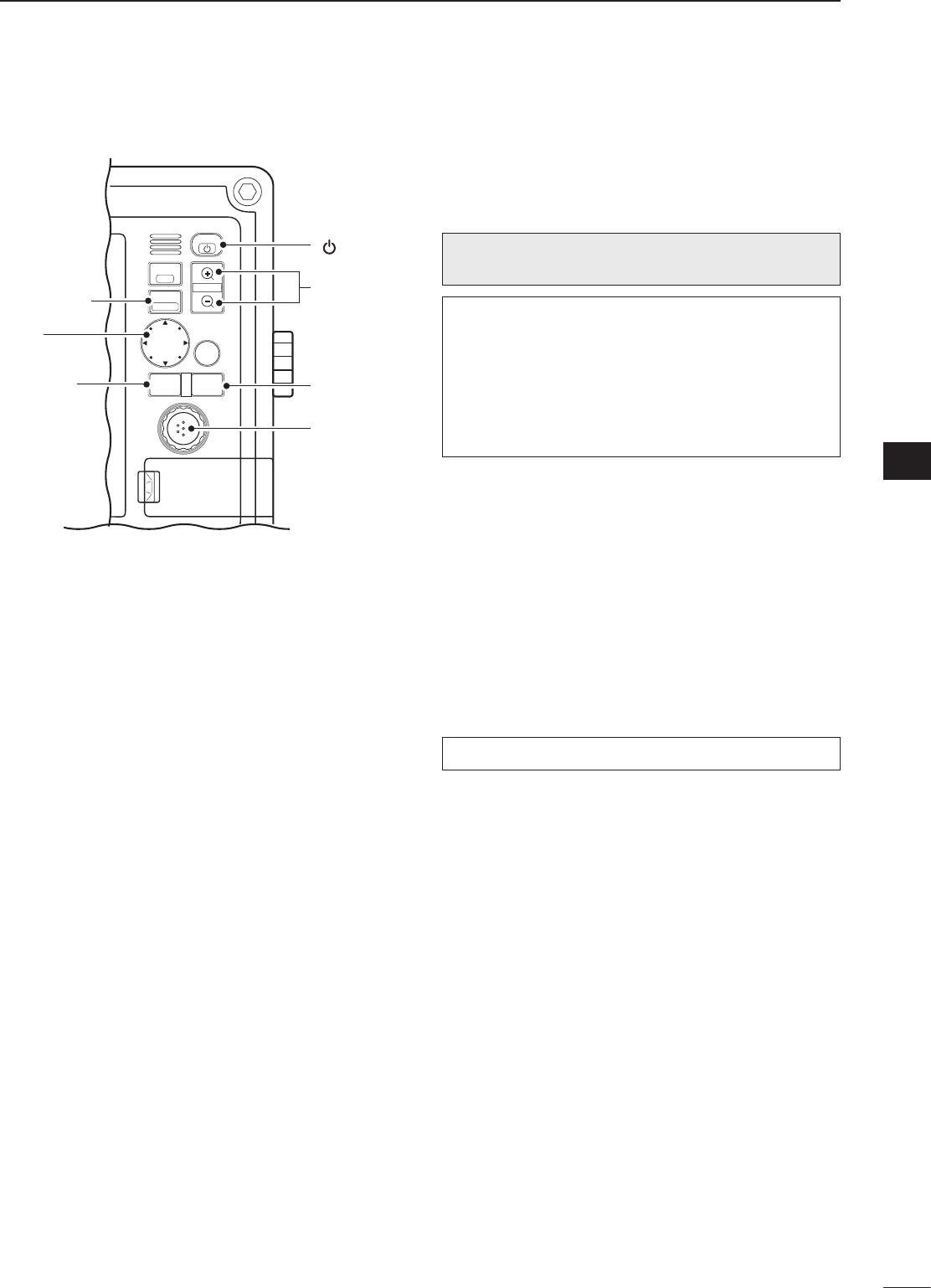
1
1
PANEL DESCRIPTION
1
2
3
4
5
6
7
8
9
10
11
12
13
14
15
16
17
18
19
20
21
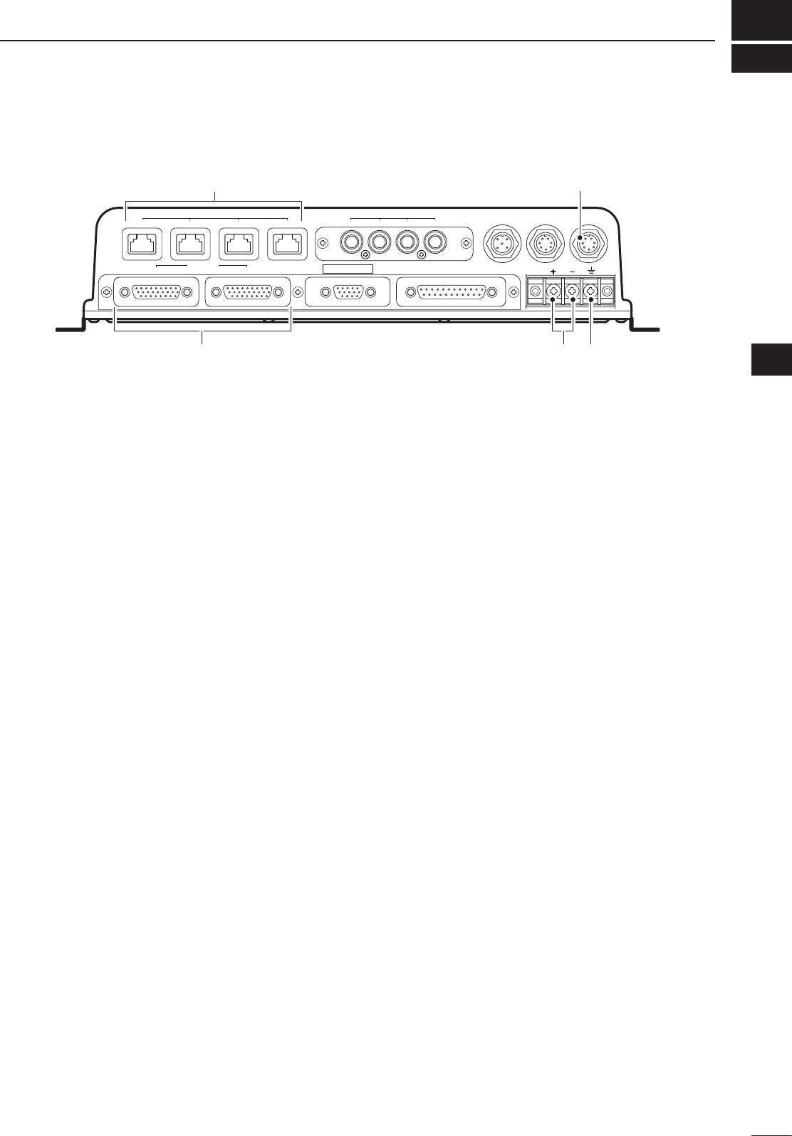
q DC POWER INPUT TERMINALS
Connect the 12 V/24 V DC power supply through
the supplied DC power cable.
w GROUND TERMINALS
Connect these terminals to ground to prevent elec-
trical shocks.
e MarineCommander™ CONNECTOR
Connect this connector to the Icom MarineCom-
mander™.
r SCANNER UNIT CONNECTOR
Connect this
connector
to the supplied scanner
unit.
qw re
This terminal is not used.
■ MXR-5000 (Radar unit)
MXR-5000T / Page 13-1-5
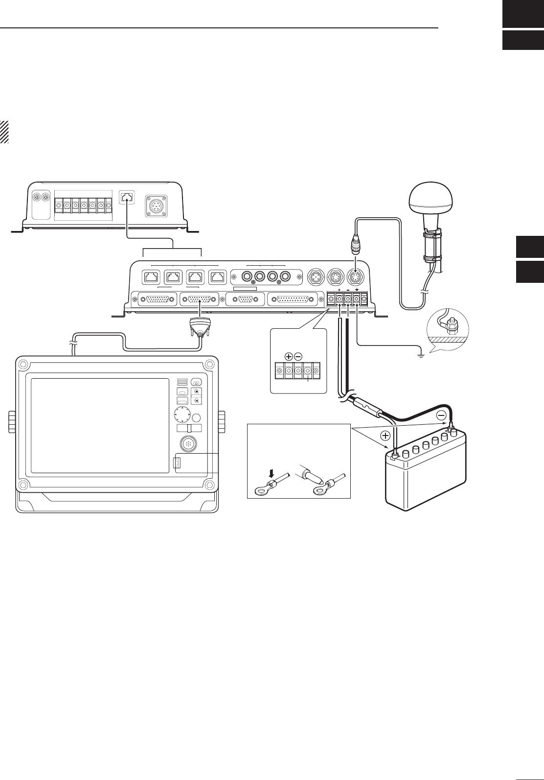
2
2
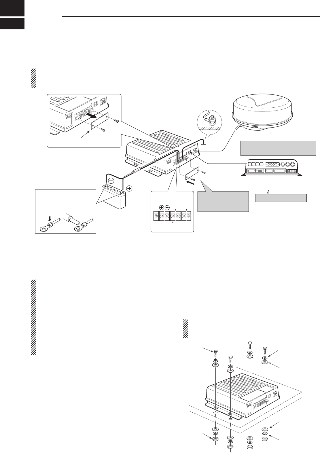
INSTALLATION AND CONNECTIONS
■ Connection
CAUTION: Before connecting, make sure discon-
necting the radar unit’s DC power cable from the
battery.
12 V/24 V
battery
Radar unit
KEEP the terminal
guard attached after
connecting cables.
NOTE: Use the termi-
nals as shown below for
the cable connections.
Solder
Crimp
Tu rn the power OFF.
Ground
NEVER connect anything other
than the supplied scanner unit.
Supplied scanner unit
MarineCommander™
MXP-5000
Te rminal guard
GND
DC IN
12V/24V
NC
Detach the terminal guard first.
■ Power source requirement
CAUTION: Before connecting the DC power cable,
check the following important items. Make sure:
• Output voltage of the power source is 12 V/24 V
DC.
• DC power cable polarity is correct.
Red : Positive + terminal
Black : Negative _ terminal
• Fuse rating of the DC power cable is correct. (The
10 A fuse is pre-installed.)
5 A : For 24 V power source
10 A : For 12 V power source
■ Ground connection
To prevent electrical shocks and other problems,
ground the radar unit through the [GND] terminal. For
best results, connect a heavy gauge wire or strap to
the nearest grounding point on the boat. The distance
between the [GND] terminal and the ground point
should be as short as possible.
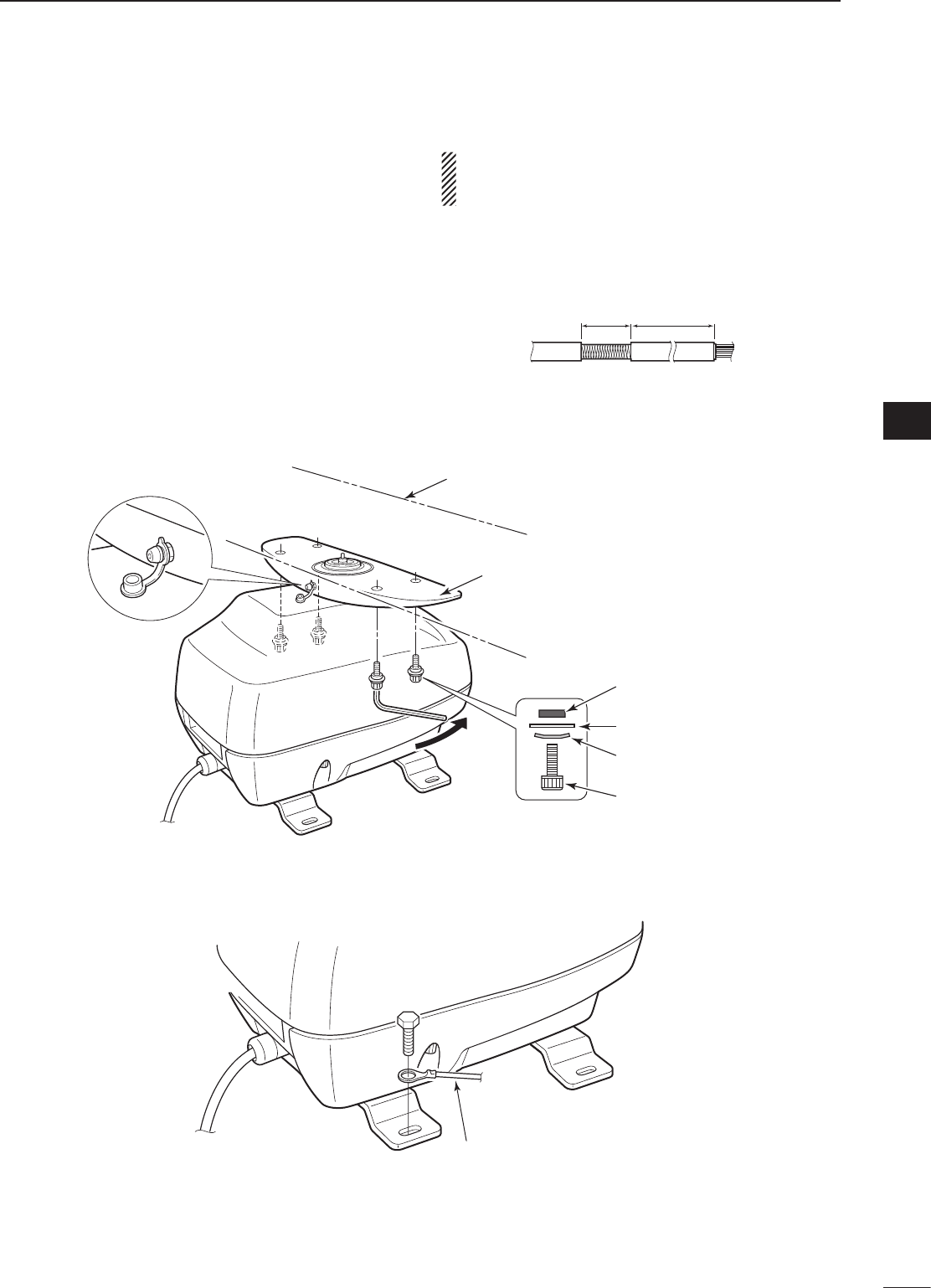
■ Mounting
First, drill four Ø5.5–6 mm (7⁄32–1⁄4") holes to mount
the radar unit using the units base as a pattern.
Mount the radar unit securely with the four supplied
bolts (M5×30 mm) to a flat surface which supports
more than approx. 5 kg (11 lb).
CAUTION: KEEP the radar unit at least 1.8 meter
(5.9 ft) away from your vessel’s magnetic naviga-
tion compass.
Flat washer
Flat washer
Spring washer
Spring washer
Bolt
Nut
MXR-5000T / Page 13-1-6
3
2
INSTALLATION AND CONNECTIONS
1
2
3
4
5
6
7
8
9
10
11
12
13
14
15
16
17
18
19
20
21
DLocation
R WARNING! BE SURE
the radar’s power
is OFF*
whenever you are working with the scanner unit.
* The radar’s power automatically turns OFF approx. 30 sec.
after the display unit’s power is turned OFF.
When 2 display units are connected to the
MarineCommander™, all units’ power must be turned OFF.
The scanner unit is designed for high-pressure water
jet resistance (except for the cable connectors). Select
a place for installation which meets the following im-
portant conditions.
q The scanner unit must be near the boat’s center line
and have a good view in every direction. Be sure
there are no objects in the surrounding area which
will intercept the scanning beam.
w Keep the scanner unit away from any smoke-stacks.
Smoke can damage the unit.
e When the boat is equipped with a Radio Directional
Finder (RDF) system, keep the scanner unit at least
2 m (6.6 ft) away from any RDF antenna.
• Radiation from the scanner unit can affect the measure-
ment data of RDF equipment.
r The unit should be placed as high as possible on
the boat to obtain best performance with maximum
range.
t If you install two or more radar in one boat, install
one above, and one below.
y The mounting surface must be parallel with the
boat’s waterline.
u If the height is insufficient to install the scanner unit,
build a special frame for installation.
DMounting
q Drill four holes of 12 mm (1⁄2 in) in diameter using
the supplied template.
w If the mounting surface or platform is metal, apply
sealing compound around the holes to prevent cor-
rosion and to waterproof the unit.
e Attach the scanner unit to the selected position with
the supplied bolts (M10×50 mm or M10×25 mm; de-; de-
pending on your installation needs), flat and spring
washers.
CAUTION: SECURE the four bolts firmly.
607 (2329⁄32)
45.5 (113⁄16) 150.5 (515⁄16)
243 (99⁄16)
90.5 (39⁄16)90.5 (39⁄16)
Ship’s bow direction Ship’s bow direction
Unit: mm (in)
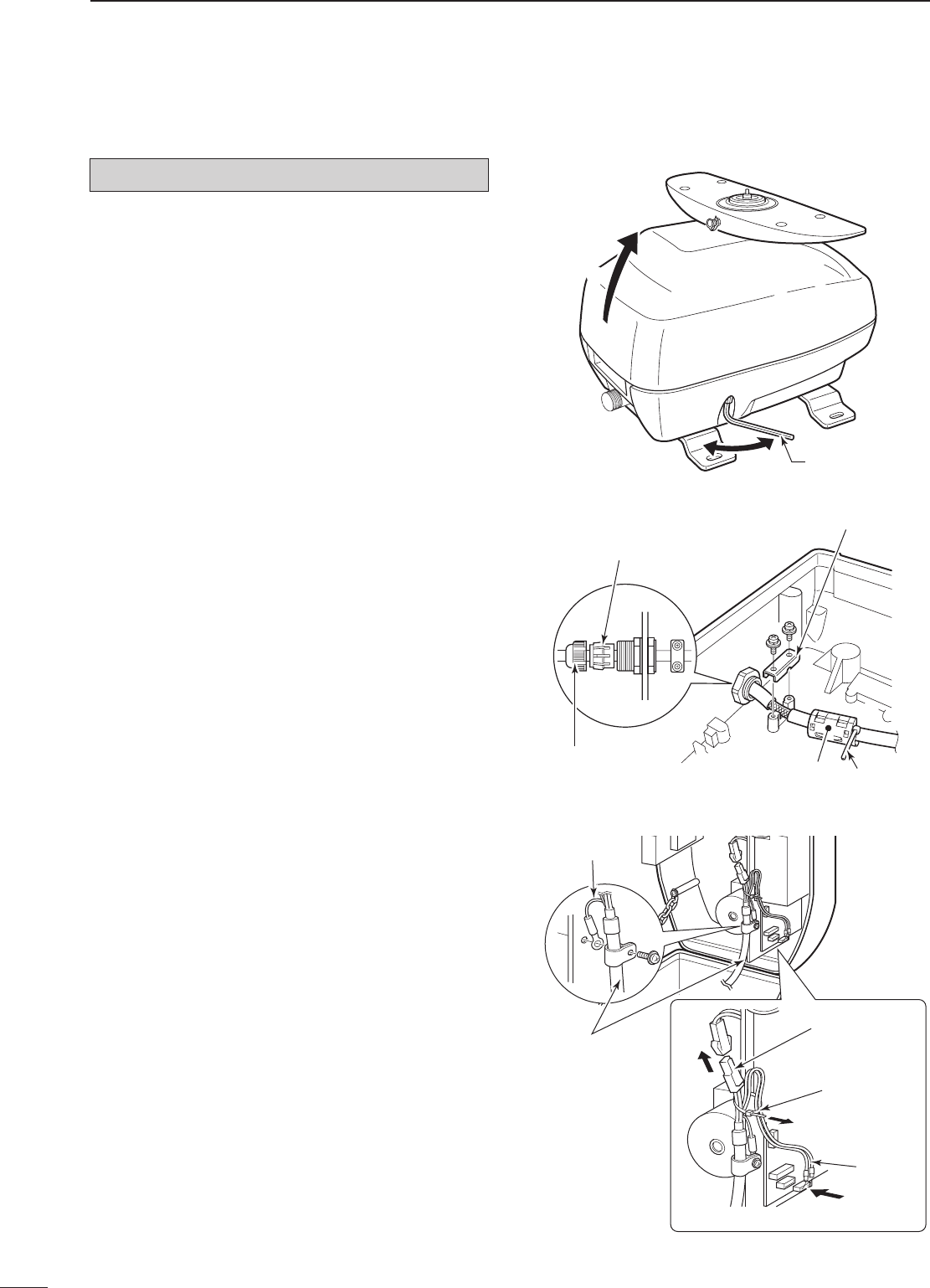
■ Mounting the EX-2714 scanner unit
MXR-5000T / Page 13-1-7
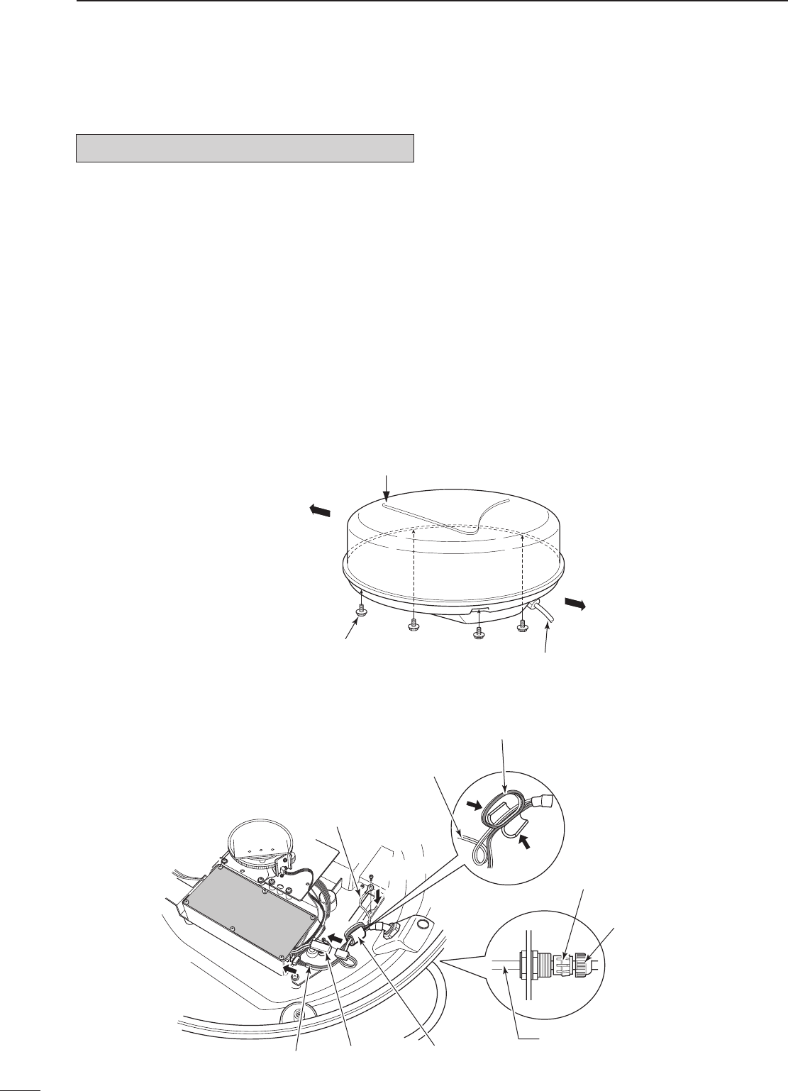
■ Wiring the EX-2714 system cable
CAUTION: NEVER cut the supplied system cable.
q Using a hex head wrench*, loosen the four bolts on
the bottom of the scanner unit, and open the unit.
* Phillips head or flathead screwdriver is also usable.
w Loosen the sealing nut on the scanner unit and
pass the system cable through the sealing nut and
tube. (q)
e Insert the black and white PA cable connector into
the PA unit connector J1. (w)
r Connect the shielded cable ground wire to the
ground plate with the screw. (e)
t Clamp the system cable with the ferrite bead at-
tached near the sealing connector.
Be sure to clamp it tightly. (r)
y Connect the power cable (black and red) to the
power connector. (t)
u Tighten the sealing nut, then replace the radome
cover over the scanner unit.
DO NOT stretch the system cable too much, other-
wise miss contact of the connector may occur.
i Tighten the four bolts on the bottom of the scanner
unit. (Use a torque wrench until the scale on the
wrench reads torque to 5.0 N•m; 3.69 lbf•ft.)
• The four projections around the circumference of the ra-
dome cover show the positions of the bolt receptacles.
• Scanner unit assembly (cover removed)
Ship’s bow direction
Face the Ω mark in the direction
of the ship’s bow.
Stern
System cable
Scanner unit assembly
Bolt
• Connect the system cable
Ferrite bead
Shielded cable
ground wire
w
t
PA cable Power
connector
e
Power cable
PA cable (Loop the PA cable twice.)
q
r
Sealing tube
Sealing nut
System cable
4
2INSTALLATION AND CONNECTIONS
MXR-5000T / Page 13-1-8
5
2
INSTALLATION AND CONNECTIONS
1
2
3
4
5
6
7
8
9
10
11
12
13
14
15
16
17
18
19
20
21
DLocation
R WARNING! BE SURE
the radar’s power
is OFF*
whenever you are working with the scanner unit.
* The radar’s power automatically turns OFF approx. 30 sec.
after the display unit’s power is turned OFF.
When 2 display units are connected to the
MarineCommander™, all units’ power must be turned OFF.
The scanner unit is designed for high-pressure water
jet resistance (except for the cable connectors). Select
a place for installation which meets the following im-
portant conditions.
q The scanner unit must be near the boat’s center line
and have a good view in every direction. Be sure
there are no objects in the surrounding area which
will intercept the scanning beam.
w Keep the scanner unit away from any smoke-stacks.
Smoke can damage the unit.
e When the boat is equipped with a Radio Directional
Finder (RDF) system, keep the scanner unit at least
2 m (6.6 ft) away from any RDF antenna.
• Radiation from the scanner unit can affect the measure-
ment data of RDF equipment.
r The unit should be placed as high as possible on
the boat to obtain best performance with maximum
range.
t If you install two or more radar in one boat, install
one above, and one below.
y The mounting surface must be parallel with the
boat’s waterline.
u If the height is insufficient to install the scanner unit,
build a special frame for installation.
DMounting
q Drill four holes of 12 mm (1⁄2 in) in diameter using
the supplied template.
w If the mounting surface or platform is metal, apply
sealing compound around the holes to prevent cor-
rosion and to waterproof the unit.
e Attach the scanner unit to the selected position with
the supplied bolts (M10×40 mm), flat and spring
washers.
CAUTION: SECURE the four bolts firmly.
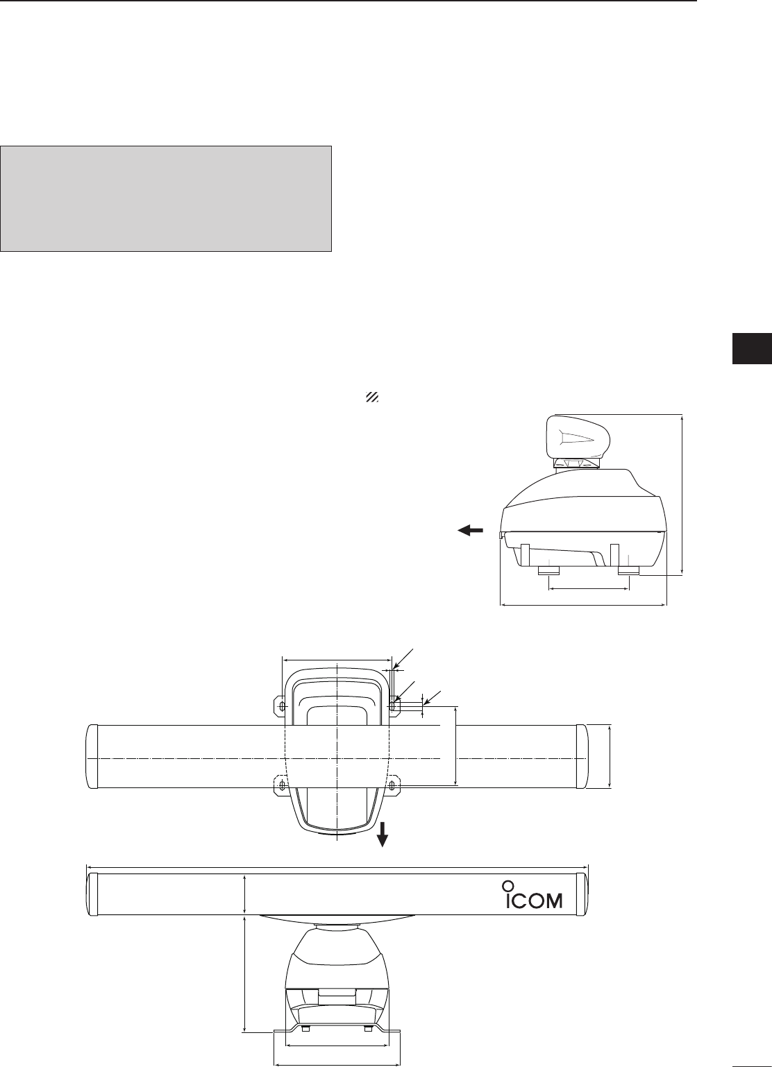
Ship’s bow direction
190 (715⁄32)
399 (1723⁄32)
381 (15)
■ Mounting the EX-2780 scanner unit
Ship’s bow direction
302 (1129⁄32)
248 (93⁄4)
1200 (471⁄4)
20.5 (13⁄16)
R5.5 (7⁄32)
11 (7⁄16)
262 (105⁄16)
281 (111⁄16) 98 (37⁄8)
152 (531⁄32)
190 (715⁄32)
MXR-5000T / Page 13-1-9
CAUTION: NEVER cut the supplied system cable.
q Loosen the four bolts on the bottom of the scan-
ner body using the supplied allen wrench (q), and
open the top cover (w).
w Loosen the nut on the scanner unit and pass the
system cable through the nut and sealing tube. (e)
e Connect the power cable (black and red) connec-
tor to the power unit connector through the looped
cable tie. (r)
r Insert the PA cable (black and white) connector into
the PA unit connector. Be sure to follow the diagram
below carefully. (t)
• Secure the looped PA cable with the looped cable tie
(y).
t Connect the shielded cable ground wire to the
chassis with the screw as shown in the diagram.
(u)
y Clamp the system cable with the cable clamp metal
fitting using a screw near the sealing connector.
(i)
Be sure to clamp it tightly.
u Clamp the system cable with the ferrite bead at-
tached near the sealing connector. (o)
Be sure to clamp it tightly.
Secure the ferrite bead with cable tie.
i Tighten the sealing-nut, then close the top cover.
DO NOT stretch the system cable too much, other-
wise miss contact of the connector may occur.
o Tighten the four bolts on the bottom of the scanner
body. (Use a torque wrench until the scale on the
wrench reads torque to 9.8 N•m; 7.23 lbf•ft.)
Allen wrench
Scanner body
q
w
Ferrite bead Cable tie
Cable clamp
i
o
Sealing tube
Sealing Nut
e
Shielded cable
ground wire
System cable
u
r
t
Looped
cable tie
Power cable
PA cable
y
■ Wiring the EX-2780 system cable
Fig.1
Fig.2
Fig.3
6
2INSTALLATION AND CONNECTIONS
MXR-5000T / Page 13-1-10
7
2
INSTALLATION AND CONNECTIONS
1
2
3
4
5
6
7
8
9
10
11
12
13
14
15
16
17
18
19
20
21
q Put the scanner unit on the stay, then attach the an-
tenna rotor with the supplied bolts (M8×18 mm), flat
and belleville washers and a sealing washer.
Be sure to install the belleville washer in the direc-
tion as shown below. (Fig. 1)
w Apply the lubricant specified below, or an equivalent
one, to the motor bearing, if required.
• Manufacture : ESSO
Type : BEACON 325
e Connect the grounding wire (purchase locally) to the
ground plate with the supplied terminal if required.
(Fig. 2)
NOTE: When using the optional system cable.
Peel the outer sheath of the system cable when
using the optional system cable OPC-1078.
BE CAREFUL! DO NOT cut the inner shield wire when
peeling the outer sheath.
Unit: mm (inch)
�
�
Peel the sheath
To the displayTo the scanner
■ Attaching the EX-2780 scanner unit
Scanner unit
Stay
Sealing washer
Flat washer
Belleville washer
(Install in this direction)
Bolt
Lubrication fitting place
Grounding wire
Fig.1
Fig.2
18±2
(23⁄32±3⁄32)
410±5
(165⁄32±3⁄16)
MXR-5000T / Page 13-1-11
■ Periodic maintenance
q Keep the equipment as clean as possible.
• Use a soft cloth to remove dirt, dust and water.
w Check all hardware for loose screws, bolts, etc.
e Check cables and terminal connections.
■ Scanner unit maintenance
DCleaning
q Wipe the surface of the scanner unit with a clean
soft cloth.
• DO NOT use harsh solvents such as benzene or alco-
hol.
w Check that there is no dirt or caked-on salt.
• A heavy deposit of dirt or caked-on salt on the painted
surface of the upper scanner unit will cause a consider-
able drop in radar performance.
e Check for cracks or deterioration of the rubber
packing and replace it, if necessary.
DPainting (MXR-5000T only)
To prevent the corrosion, paint the surface of the
scanner body (except the scanner unit) once or twice
a year.
DMounting
Check the mounting bolts of the scanner unit and
tighten, if necessary.
■ Fuse replacement
If the fuse blows or the radar stops functioning, find
the source of the problem and have it repaired. Then,
replace the blown fuse with a new, properly rated one
as shown at right.
■ Options
• OPC-1895 c o n n e c t i o n c a b l e
Allows you to connect the Icom MarineCommander™
system. (20 m: 65.6 ft)
• OPC-1077 s y s t e m c a b l e
Allows you to install the radar unit and scanner unit
up to 20 m (65.6 ft) apart. (For MXR-5000R only)
• OPC-1078 s y s t e m c a b l e
Allows you to install the radar unit and scanner unit
up to 30 m (98.4 ft) apart.
Fuse rating: 10 A for 12 V power source
5 A for 24 V power source
Approved Icom optional equipment is designed for opti-
mal performance when used with an Icom transceiver.
Icom is not responsible for the destruction or damage to
an Icom transceiver in the event the Icom transceiver is
used with equipment that is not manufactured or approved
by Icom.
Continued, reliable operation of the radar depends on
how you care for your equipment.
The simple maintenance tips that follow can help you
save time and money, and avoid premature equipment
failures.
R WARNING! BE SURE
the radar’s power
is OFF*
before performing any maintenance.
* The radar’s power automatically turns OFF approx. 30 sec.
after the display unit’s power is turned OFF.
When 2 display units are connected to the
MarineCommander™, all units’ power must be turned OFF.
3
8
MAINTENANCE AND OPTIONS
MXR-5000T / Page 13-1-12

4
9
SPECIFICATIONS
1
2
3
4
5
6
7
8
9
10
11
12
13
14
15
16
17
18
19
20
21
D Radar unit
• DC input voltage : 10.8 V to 31.2 V DC
• Power consumption : Less than 5.0 A at 12.0 V (MXR-5000R)
Less than 5.5 A at 12.0 V (MXR-5000T)
• Usable temperature range : –20°C to +60°C; –4˚F to 140˚F
• Dimensions (projections not included) : 250(W)×67(H)×200(D) mm; 927⁄32(W)×25⁄8(H)×77⁄8(D) in
• Weight (approx.) : 2.1 kg; 4.62 lb
D Scanner unit
◆ EX-2714 (Radome)
• Type : 60 cm (2 ft.) Slotted Waveguide Array, enclosed in a
radome.
• Rotation speed (typical) : 24 rpm, 36 rpm, 48 rpm
• Beam width (typical) : Horizontal beam 4˚
Vertical beam 22˚
• Side lobe (typical) : –18 dB
• Polarization : Horizontal
• Transmission frequency : 9410 MHz ±30 MHz P0N
• Peak output power : 4 kW
• Pulse width : 80 ns/2880 Hz, 80 ns/2160 Hz, 250 ns/2160 Hz,
350 ns/2160 Hz, 900 ns/720 Hz.
• Mixer and Local Oscillator : Microwave Integrated Circuit
• Transmitting Tube : Magnetron MAF1421B
• Modulator : FET switching
• Duplexer : Circulator
• Tuning system : Automatic/manual selectable
• Intermediate frequency : 60 MHz
• IF Band width : 10 MHz, 3 MHz
• Dimensions : 607 (Ø)*×243 (H) mm; 2329⁄32 (Ø)*×99⁄16 (H) in
*“Ø” means diameter.
• Usable temperature range : –25˚C to +70˚C; –13˚F to 158˚F
• Relative Humidity : Less than 95% at 35˚C (+95˚F)
• Weight (approx.) : 8 kg; 17.5 lb (without cable)
◆ EX-2780 (Open array)
• Type : 120 cm (4 ft.) Slotted Waveguide Array
• Rotation speed (typical) : 24 rpm, 36 rpm, 48 rpm
• Beam width (typical) : Horizontal beam 2˚
Vertical beam 25˚
• Side lobe (typical) : –24 dB
• Polarization : Horizontal
• Transmission frequency : 9410 MHz ±30 MHz P0N
• Peak output power : 4 kW
• Pulse width : 80 ns/2880Hz, 80 ns/2160 Hz, 250 ns/2160 Hz,
350 ns/2160 Hz, 900 ns/720 Hz
• Mixer and Local Oscillator : Microwave Integrated Circuit
• Transmitting Tube : Magnetron MAF1421B
• Modulator : FET switching
• Duplexer : Circulator
• Tuning system : Automatic/manual selectable
• Intermediate frequency : 60 MHz
• IF Band width : 10 MHz, 3 MHz
• Diameter of rotation/height : 1205/381 mm; 47.4/15 in
• Usable temperature range : –25˚C to +70˚C; –13˚F to 158˚F
• Relative Humidity : Less than 95% at 35˚C (+95˚F)
• Weight (approx.) : 17 kg; 37.4 lb (without cable)
All stated specifications are subject to change without notice or obligation.
MXR-5000T / Page 13-1-13

MEMO
MXR-5000T / Page 13-1-14

MEMO
MXR-5000T / Page 13-1-15

1-1-32 Kamiminami, Hirano-ku, Osaka 547-0003, Japan
A-6752H-1EX-w
Printed in Japan
© 2009–2010 Icom Inc.
MXR-5000T / Page 13-1-16

INSTRUCTION MANUAL
MARINE PLOTTER
DISPLAY UNIT
MXP-5000
MXD-5000
This device complies with Part 15 of the FCC Rules. Opera-
tion is subject to the following two conditions: (1) this device
may not cause harmful interference and (2) this device must
accept any interference received, including interference that
may cause undesired operation.
MXR-5000T / Page 13-2-1

i
Icom, Icom Inc. and the Icom logo are registered trademarks of
Icom Incorporated (Japan) in Japan, the United States, the United
Kingdom, Germany, France, Spain, Russia and/or other countries.
MarineCommander is a trademark of Icom Incorporated.
All other products or brands are registered trademarks or trade-
marks of their respective holders.
PRECAUTIONS
R WARNING! NEVER let metal, wire or other
objects touch any internal part or terminals of the
Main unit. This may result in an electric shock.
R WARNING! NEVER apply AC voltage to the
DC input terminals of the Main unit. This may pose a
fire hazard, result in an electric shock or damage the
Main unit.
R WARNING! NEVER apply more than 32 V
DC to the DC input terminals of the Main unit or
use reverse polarity. This may pose a fire hazard or
damage the Main unit.
R WARNING! NEVER cut the DC power cable
between the DC plug and fuse holder. If an incorrect
connection is made after cutting, the Main unit may
be damaged.
R WARNING! NEVER touch the Main unit with
wet hands. This may result in an electric shock or
damage the Main unit.
R WARNING! NEVER open the bottom cover of
the Main unit. There are no user adjustment points.
This may result in an electric shock and incorrect
reassembly may cause a fire hazard.
DO NOT place the Main unit in excessively dusty
environments.
D O NOT place the Main unit near heating
equipment or in direct sunlight or where hot or cold air
blows directly onto it.
DO NOT use or place the Main unit in areas with
temperature below –20˚C (–4˚F) or above +60˚C
(+140˚F).
DO NOT place the Main unit in areas that will block
air passage or put anything around the Main unit. This
will obstruct heat dissipation.
DO NOT
use harsh solvent such as benzine or
alcohol to clean the Main unit, as they will damage
the Main unit’s surfaces.
KEEP the Main unit out of the reach of children.
KEEP the Main unit away from heavy rain, and never
immerse it in the water.
The Main unit meets IPX4 requirements for splash
resistance when the supplied connection cables are
connected, and the connector cap is installed on the
other connector.
However, if it is dropped, splash resistance cannot be
guaranteed because of possible damage to the case
or the waterproof seals.
MXR-5000T / Page 13-2-2
1
1
PANEL DESCRIPTION
q GROUND TERMINAL
Connect this terminal to ground to prevent electrical
shocks.
w DC POWER INPUT TERMINALS
Connect the 12 V/24 V DC power supply through
the supplied DC power cable.
e DISPLAY UNIT CONNECTOR
Connect this
connector
to the Display unit (MXD-
5000). Two Display units can be connected.
r BLACK BOX CONNECTOR
•1to3connectors
Connect this connector to a black box unit such
as Radar unit (MXR-5000), Fish finder unit (MXF-
5000).
•4connector
Connect an other Main unit (MXP-5000).
t GPS UNIT CONNECTOR
Connect this
connector
to the GPS unit (MXG-
5000).
MAIN DATA IN/OUT
EXT-DISPLAY
NMEA2000
BLACK BOX
12 34 HEADING GPS
DC IN
DISPLAY
SUB
VIDEO IN
1234
qw
tr
e
■MXP-5000(Mainunit)
1
2
3
4
5
6
7
8
9
10
11
12
13
14
15
16
17
18
19
20
21
MXR-5000T / Page 13-2-3
2
1PANEL DESCRIPTION
q
POWER/DISPLAY BLLIANCE SWITCH
[ /BRILL]
• While the MarineCommander’s power is OFF
Push to turn ON the MarineCommander’s power.
• While the MarineCommander’s power is ON
➥ Push to turn the Radar second menu.
•DisplayBrilliance,RadarTXsetting,PanelBrilliant
and Color Palette are available.
•Pushtwoormoretimestoincreaseordecrease
the display brilliance.
➥ Hold down for 3 seconds to turn OFF the Mari-
neCommander’s power.
w WAYPOINT/MAN OVERBOARD SWITCH
[WPT/MOB]
➥ Push to enter the Waypoint screen.
•Waypointwindowappears.
➥ Hold down for 3 seconds to mark the man over-
board point on the screen. When a crew mem-
ber falls overboard.
•MOBreadoutshowsthebearinganddistancetothe
MOBpoint.
•Push[MOB]for3secondstocancelthefunction.
•Positionandbearingdataarenecessary.
e RANGE UP/ DOWN SWITCHES [+]/[–]
Push[+]or[–]tosetasuitablescreenrange.
r FOCUS/DISPLAY LAYOUT SWITCH
[FOCUS/LAYOUT]
➥ Push to change the selected screen.
•Orangeboxindicatestheselectedscreen.
➥ Hold down for 3 seconds to enter the display se-
lection screen.
t UP, DOWN, LEFT, RIGHT KEYS [Ù Ú Ω ≈]
Set the alarm area, ATA target, etc. according to
the menu act.
Usethe[Ù][Ú]toselectmenuitem.
Pushingcenterofthe[Ù Ω]/[Ù ≈]or[Ú Ω]/[Ú
≈]allowsyoutomovethecrosslinecursortothe
upper (or lower) left or right.
y SUB MENU SWITCH [SUB]
While entering the Menu screen, push to enter the
Sub menu.
u MENU SWITCH [MENU]
Push to enter the Menu screen.
i CLEAR SWITCH [CLEAR]
Push to clear the current function.
While entering the Menu screen, push to clear and
return to the upper menu or clear the Menu screen.
o SELECTION DIAL [DIAL]
➥ While entering Menu screen, rotate to select the
Menu groups, items or options.
➥ Rotate to set the function level, such as Gain,
SEA or Rain level.
!0 ENTER SWITCH
➥ Push enter the Radar 1st menu.
•Radar1stmenuincludestheGaincontrol,Sea,
Rain, Radar TX menu and Heading line OFF func-
tion.
➥ While entering Menu screen, push enter the se-
lected menu or function.
P
U
S
H
T
O
E
N
T
E
R
MENU
WPT
FOCUS
LAYOUT
MOB
CLEAR
SUB
BRILL
RANGE
q
w
e
r
t
y
u
i
o
!0
■MXD-5000(Displayunit)
MXR-5000T / Page 13-2-4
2
3
INSTALLATION AND CONNECTIONS
1
2
3
4
5
6
7
8
9
10
11
12
13
14
15
16
17
18
19
20
21
■Connection
CAUTION: Before connecting, make sure discon-
necting the DC power cable from the battery.
P
U
S
H
T
O
E
N
T
E
R
MAIN DATA IN/OUT
EXT-DISPLAY
NMEA2000
MENU
WPT
FOCUS
LAYOUT
MOB
CLEAR
SUB
BRILL
BLACK BOX
12 34 HEADING GPS
DC IN
DISPLAY
SUB
VIDEO IN
1234
RANGE
GND
DC IN
12V/24V
Ground
12 V/24 V battery
NOTE: Use the termi-
nals as shown below for
the cable connections.
Solder
Crimp
Radar unit either 1 to 3 connectors
GPS unit
Display unit Main unit
MXR-5000T / Page 13-2-5

4
BASIC OPERATION
3
■TurningpowerON/OFF
q Push[ ]toturnthepowerON.
•TheinitialscreenandWARNINGscreensappear.
w Push[ENTER]tostartoperation.
•Thewarmingupscreenappears.
•
The magnetron inside the scanner unit warms up for 90
seconds.
e When the warming up is complete, the operating
screen appears to start operation.
r Push[BRILL],andthen[u],toselecttheRadarTX
menu.
t Rotate[DIAL]toselect“TX,”thenpush[ENTER]to
start scanning.
•Targetsandheadingmarkerappear.
•Thescreenappearsapproximately2secondsafter
pushing[ENTER],when“Auto”isselectedinthe
“TUNE”ofthe“Gain”menu.
Repeat step r and t,andselect“STBY,”then
push[ENTER]toreturntothestand-bymodeof
the Scanner transmission.
y Holddown[ ]for3secondstoturnthepower
OFF.
q If any other than Radar screen appears, hold
down[LAYOUT](FOCUS)for2secondstoenter
the screen selection mode.
w Rotate [DIAL] to select Radar, then push
[ENTER].
MXR-5000T / Page 13-2-6
5
3
BASICOPERATION
1
2
3
4
5
6
7
8
9
10
11
12
13
14
15
16
17
18
19
20
21
q Turn the power ON.
w Turn the Radar TX ON.
•See“TurningpowerON/OFF”onpageatleft.
e Push[+]or[–]oneormoretimestoselectthe
display range.
•Thescreenrangereadoutshowsthemaximumrange
of the screen.
r Push[ENTER]toentertheRadarsettingmenu,
thenrotate[DIAL]tosetthegainlevelontheGain
menu.
•Clockwiserotationincreasesthegain.
•Increasedgainmayincreasescreennoise.
tPush[ENTER],andthen[u]oncetoselectthe
Sea menu, to set the sensitivity time control,
rotate[DIAL]counterclockwisetosettheSEAto
minimum.
y Push[ENTER],andthen[u]twicetoselectthe
Rain menu, to set the rain clutter control, then
rotate[DIAL]counterclockwisetosetRAINto
minimum.
u Select Radar Display mode.
➥ Push[MENU],thenrotate[DIAL]untilthe
“RadarDisplayMode”menubecomes
highlighted.
➥ Push[ENTER],thenrotate[DIAL]toselectone
of Head-up; H-UP, North-up; N-UP, Course-up;
C-UP or True Motion; TM screens.
➥Push[ENTER],andthen[CLEAR]twice,toexit
the menu screen.
CAUTION: When setting of the SEA to a fully clockwise
position, close targets are blanked.
DHeadingmarker
The heading marker is a line that shows your ship’s
bow direction. (This marker will appear in the center
of the screen when the Head-up screen H UP is
selected.) The heading marker can be hidden when
the desired target is located under the heading
marker.
•Push[ENTER]toentertheRadarmenu,thenpush[u]
four times to select the Heading marker menu. Hold down
[ENTER]tohidetheheadingmarker.Release[ENTER]to
return.
DFixedrangerings
The fixed range rings can be used for rough distance
measurement.
➥ Push[MENU],thenrotate[DIAL]untilthe
“Presentation”menubecomeshighlighted.
➥ Push[ENTER],thenrotate[DIAL]untilthe“Ring”
menu becomes highlighted.
➥ Push[ENTER],thenrotate[DIAL]toselectone
of Ring-OFF; OFF or any other three Ring levels;
Low, Mid, High.
➥Push[ENTER],andthen[CLEAR]twice,toexitthe
menu screen.
DManualtuning
The receiver tuning can be manually adjusted.
➥ Push[MENU],andthen[ENTER],toenterthe
Gainmenu.Thenrotate[DIAL]untilthe“Tune”
menu becomes highlighted.
➥ Push[ENTER],thenrotate[DIAL]toselectthe
“Manual...”menuandpush[ENTER]toturnthe
manualtuninglevelindicator,thenrotate[DIAL]to
setthe“TuneLevel”metertothemaximumlevel.
➥Push[ENTER]toexitthemanualtuningscreen.
DBrillianceadjustment
The intensity of the screen can be adjusted. When
you require continuous operation, but not constant
viewing, a lower setting can increase the life of the
LCD display.
•Keyillumination
The backlighting of the keys can be adjusted for
convenient operation.
Push[BRILL],andthen[u]threetimes,tocallupthe
“PanelBrill”menu.Thenrotate[DIAL]toselecttheil-
lumination level.
NOTE: Manual adjustment can be used. (See below.)
MENU
WPT
FOCUS
LAYOUT
MOB
CLEAR
SUB
BRILL
RANGE
u
[ENTER]
[CLEAR]
[MENU]
[�]
[LAYOUT] [+] or [–]
(RANGE)
[ ]
■Basicoperation
You can automatically set SEA control.
➥ Push[MENU],thenrotate[DIAL]untilthe“Gain”
menu becomes highlighted.
➥ Push[MENU],thenrotate[DIAL]untilthe“Auto
Sea”menubecomeshighlighted.
➥ Push[ENTER],thenrotate[DIAL]toselect“ON.”
➥Push[ENTER],andthen[CLEAR]twice,toexitthe
menu screen.
MXR-5000T / Page 13-2-7
6
3BASICOPERATION
This function eliminates reflection echoes from rain,
snow, fog etc.
qPush[MENU],andthen[ENTER],toenterthe
Gain menu.
wRotate[DIAL]untilthe“Rain...”menubecomes
highlighted.
ePush[ENTER]toturntheRainlevelindicator.
rRotate[DIAL]toadjusttheRainlevel.
•NOTE: DO NOT reduce the reflection echoes too
much, otherwise you may miss weaker targets.
tPush[ENTER]toexittheRainadjustmentscreen.
This function serves to eliminate echoes from waves at
close range. Reduce the receiver gain for close objects
within a radius of 8 miles to eliminate sea clutter.
qPush[MENU],andthen[ENTER],toenterthe
Gain menu.
wRotate[DIAL]untilthe“Sea...”menubecomes
highlighted.
ePush[ENTER]toturntheSEAlevelindicator.
rRotate[DIAL]toadjustSEAlevel.
tPush[ENTER]toexittheSEAadjustmentscreen.
The scanning area can be shifted in a desired
direction and can be enlarged partially. This is useful
when the Head-up* is selected and you want to
enlarge the bow direction display, or, the center of the
screen shifts in the direction of the intersection.
qPush[MENU]toentertheMenuscreen.
wRotate[DIAL]untilthe“CenterShift”menu
becomes highlighted.
ePush[ENTER]thenrotate[DIAL]toselectthe
“ON...”option.
rPush[ENTER]toactivatetheCenterShiftfunction.
•TheCursorwindowappearsintheupperrightofthe
screen.
•Thisfunctionisavailablefor24NMorshorterrange
selection.
*This function is not available in the TM screen.
tPush[Ù Ú Ω ≈] to move the cursor where you
want to shift the center of the screen.
•Max.offsettingisupto75%ofthescreen.
yPush[ENTER]toshiftthescreen.
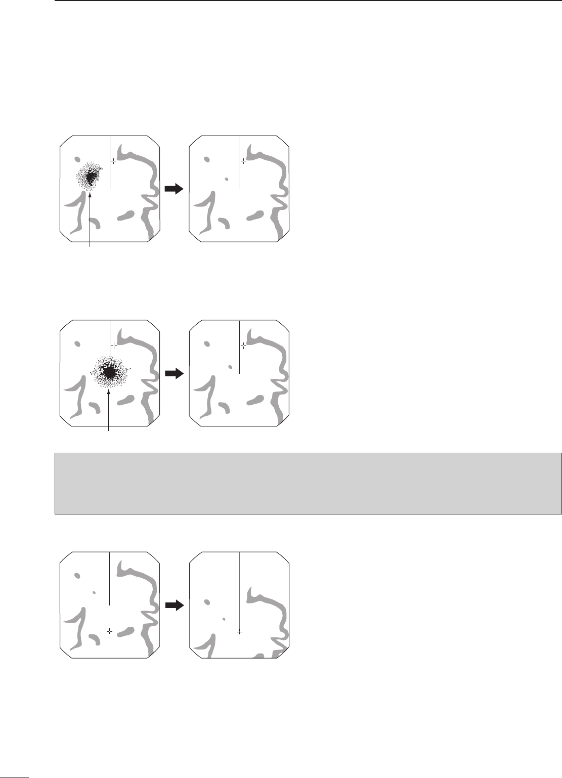
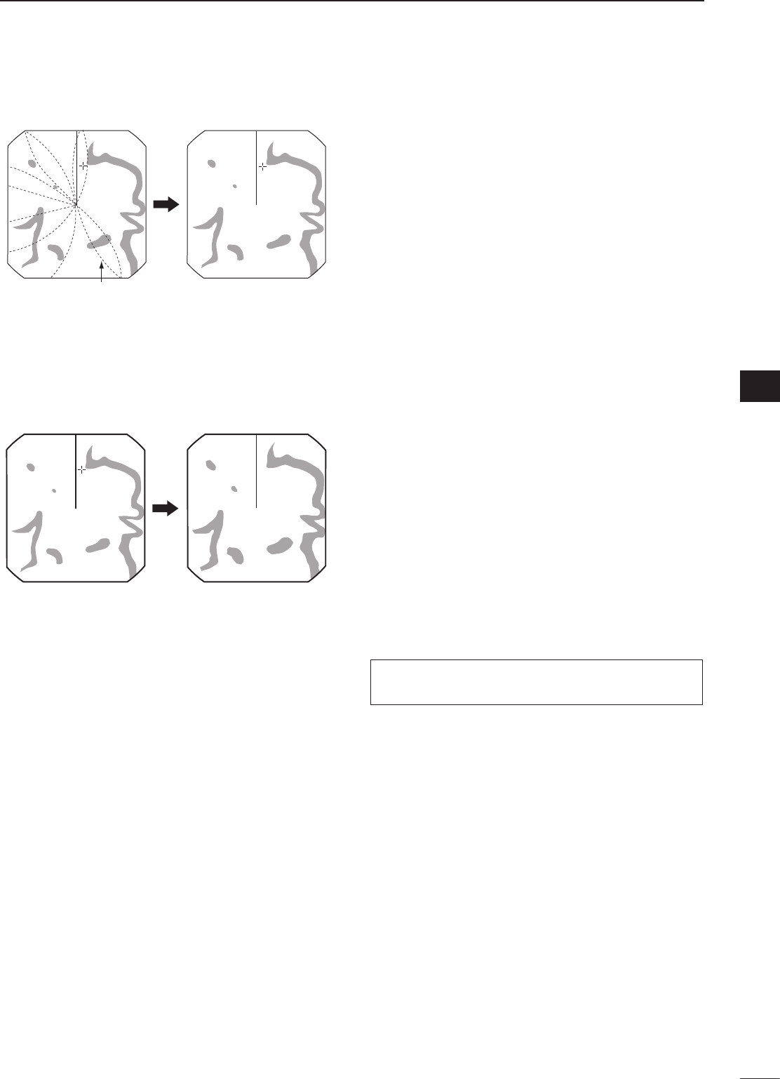
The following are typical basic operation examples, which may hinder radar reception (sea clutter, precipitation
interference and echoes from other radar).
■RAINfunction(MENU w Gain u Rain...)
WARNING: The SEA function reduces the receiver sensitivity of objects within 8 miles. Therefore, caution and
careful adjustment are necessary when using the SEA function.
Small objects may not be displayed on the screen when strong echoes from the rain or the island within 1 NM while
automatic SEA function is activating.
Adjust RAIN control
Small echos
With OFF CENTER ON
Normal screen
■SEAfunction (MENU w Gain u Sea...)
Adjust SEA control
Echos from sea waves
■CENTERSHIFTfunction MENU w CenterShift
MXR-5000T / Page 13-2-8
7
3
BASICOPERATION
1
2
3
4
5
6
7
8
9
10
11
12
13
14
15
16
17
18
19
20
21
The ZOOM function expands the target to two times
normal size.
qPush[MENU]toentertheMenuscreen.
wRotate[DIAL]untilthe“Zoom”menubecomes
highlighted.
ePush[ENTER]thenrotate[DIAL]toselectthe
“ON...”option.
rPush[ENTER]toactivatetheZoomfunction.
•TheZoom window appearsinthelowerleftofthe
screen.
t Push[Ù Ú Ω ≈]tomovethedottedboxtothe
desired target.
yPush[ENTER]tosetthezoomposition.
■IRfunction (MENU w Radar Setup u Signal Process u IR)
Radar interference may appear when another ship’s
radar is operating on the same frequency band in
close proximity. The IR function can eliminate this type
of interference.
qPush[MENU]toentertheMenuscreen.
wRotate[DIAL]untilthe“RadarSetup”menu
becomes highlighted.
ePush[ENTER]thenrotate[DIAL]untilthe“Signal
Process”menubecomeshighlighted.
rPush[ENTER]thenrotate[DIAL]untilthe“IR”
menu becomes highlighted.
tPush[ENTER]thenrotate[DIAL]toselecttheIR
function,1,2orOFF.Push[ENTER].
•“IR1”or“IR2”appearsintheupperleftofthescreen,
when the function is activated.
■STRETCHfunction (MENU w Radar Setup u Signal Process u Stretch)
The blips can be magnified electronically for easier
viewing of small targets.
qPush[MENU]toentertheMenuscreen.
wRotate[DIAL]untilthe“RadarSetup”menu
becomes highlighted.
ePush[ENTER]thenrotate[DIAL]untilthe“Signal
Process”menubecomeshighlighted.
rPush[ENTER]thenrotate[DIAL]untilthe“Stretch”
menu becomes highlighted.
tPush[ENTER]thenrotate[DIAL]toturnthe
functionON.Push[ENTER].
•“ES”appearsintheupperleftofthescreen,whenthe
function is activated.
NOTE: Turn OFF this function during normal opera-
tion.
With STRETCH ON
Normal screen
■ZOOMfunction (MENU w Zoom)
With IR function ON
Radar interference
MXR-5000T / Page 13-2-9

8
3BASICOPERATION
The trails function memorizes echoes continuously or
at constant intervals. This is useful for watching other
ships’ tracks, approx. relative speed, etc.
Trail time
•Settingthetrailintervaltime
(MENU w Trail u Trail Setup u Trail Time)
qPush[MENU]toentertheMenuscreen.
wRotate[DIAL]untilthe“Trail”menubecomes
highlighted.
ePush[ENTER]thenrotate[DIAL]untilthe“Trail
Setup”menubecomeshighlighted.
rPush[ENTER]thenrotate[DIAL]untilthe“Trail
Time”menubecomeshighlighted.
tPush[ENTER]thenrotate[DIAL]toselecta
desiredtrailintervaltime.Push[ENTER].
•6seconds,15seconds,30seconds,1minute,3min-
utes, 6 minutes, 15 minutes, 30 minutes and ∞ (con-
tinuous) are selectable.
y Push[CLEAR]threetimestoexitthemenuscreen.
•Settingthetrailcolor
(MENU w Trail u Trail Setup u Trail Color)
qPush[MENU]toentertheMenuscreen.
wRotate[DIAL]untilthe“Trail”menubecomes
highlighted.
ePush[ENTER]thenrotate[DIAL]untilthe“Trail
Setup”menubecomeshighlighted.
rPush[ENTER]thenrotate[DIAL]untilthe“Trail
Color”menubecomeshighlighted.
tPush[ENTER]thenrotate[DIAL]toselecta
desiredtrailcolor.Push[ENTER].
•Blue,Yellow,Green,Red,Orange,WhiteandMulti
(mixed color) are selectable.
y Push[CLEAR]threetimestoexitthemenuscreen.
•UsingtheTRAILSfunction(MENU w Trail u Trail)
qPush[MENU]toentertheMenuscreen.
wRotate[DIAL]untilthe“Trail”menubecomes
highlighted.
ePush[ENTER]thenrotate[DIAL]untilthe“Trail”
menu becomes highlighted.
rPush[ENTER]thenrotate[DIAL]toselectthetrail
functionON.Push[ENTER].
•“TRAILS”andtrailintervaltimeappearsintheupper
left of the screen.
•Trailintervalcounterstartstocountuptothetrailtime.
t All displayed echoes at the plotted time are
memorized and displayed with a graduated
intensity together with the current echoes.
•Echoesaredisplayedwithminimumintensitywhen“∞”
is selected.
y To cancel the trail function, repeat steps q to r
and select OFF.
•“TRAILS”andtrailintervaltimedisappears.
■TRAILSfunction (MENU w Trail)
MXR-5000T / Page 13-2-10

9
3
BASICOPERATION
1
2
3
4
5
6
7
8
9
10
11
12
13
14
15
16
17
18
19
20
21
To magnify the blips for easier viewing of small
targets, the long pulse and echo stretch functions are
available. When the long pulse is used in the 3⁄4 to 2
NM range, this function magnifies target echoes to
the backward direction of the target.
•Pulseselection
qPush[MENU]toentertheMenuscreen.
wRotate[DIAL]untilthe“RadarSetup”menu
becomes highlighted.
ePush[ENTER]thenrotate[DIAL]untilthe“Signal
Process”menubecomeshighlighted.
rPush[ENTER]thenrotate[DIAL]untilthe“Pulse”
menu becomes highlighted.
tPush[ENTER]thenrotate[DIAL]toselecta
desiredpulsetype,“Short”or“Long.”Push
[ENTER].
y Push[CLEAR]threetimestoexitthemenuscreen.
•“SP”or“LP”appearsintheupperleftofthescreen.
NOTE: Select“Short”thisfunctionduringnormal
operation. This function reduces the target distance
resolution.
■Longpulsefunction (MENU w Radar Setup u Signal Process u Pulse)
qPush[MENU]toentertheMenuscreen.
wRotate[DIAL]untilthe“Presentation”menu
becomes highlighted.
ePush[ENTER]thenrotate[DIAL]untilthe“PPI
Area”menubecomeshighlighted.
rPush[ENTER]thenrotate[DIAL]toselecta
desiredareasize,“Nar”or“Wide.”Push[ENTER].
t Push[CLEAR]twicetoexitthemenuscreen.
■PPIareaselection
(MENU w Presentation u PPI Area)
qPush[MENU]toentertheMenuscreen.
wRotate[DIAL]untilthe“Presentation”menu
becomes highlighted.
ePush[ENTER]thenrotate[DIAL]untilthe“Echo
Color”menubecomeshighlighted.
rPush[ENTER]thenrotate[DIAL]toselecta
desiredechocolor,“Yellow-Black,”“Green-Black,”
“Red-Black,”“Multi-Black,”“Yellow-DarkBlue,”
“Green-DarkBlue,”“Multi-DarkBlue,”“Green-
White”or“Multi-White.”Push[ENTER].
t Push[CLEAR]twicetimestoexitthemenuscreen.
■EchoColorselection
(MENU w Presentation u Echo Color)
MXR-5000T / Page 13-2-11
4
10
DISTANCE AND DIRECTION MEASUREMENTS
■Distancemeasurement
TYPE DESCRIPTION
RING
Displays fixed rings.
Suitable for rough estimations from
your own ship to any target.
VRM1
Displays a variable range marker and
activatedbythe[DIAL]fortherange
marker selector.
Suitable for accurate measurements
from your own ship to a target.
VRM2
Normally functions the same as VRM1.
WhentheVRM1andEBL1selectsa
target, the center of VRM2 appears at
the intersection point.
Suitable for accurate measurements
from target to target.
Two measurement procedures are available with this
radar. Operating them separately or jointly is possible.
The Distance unit, nautical mile (nm), seemeile (sm)
orkilometer(km)isselectedinthe“InitialSetting...”in
the“General”menuofthe“Systemsetup”menu.
DUsingthexedrings
qPush[MENU]toentertheMenuscreen.
wRotate[DIAL]untilthe“Presentation”menu
becomes highlighted.
ePush[ENTER]thenrotate[DIAL]untilthe“Ring”
menu becomes highlighted.
rPush[ENTER]thenrotate[DIAL]toselectthe
RINGfunctionON,either“Low,”“Mid”or“High.”
Push[ENTER]todisplaythefixedring.
•Theringrangeisxeddependingonthescreenrange.
(See below.)
t Push[CLEAR]twiceexitthemenuscreen.
y Toclearthefixedrings,select“OFF”instepr
above.
Range (nm)
Ring (nm)
1 1.5 23468121624323648*
1⁄81⁄41⁄23⁄4
224343 43434444434
112234681212
1⁄16 1⁄81⁄81⁄41⁄41⁄21⁄2
NOTE: When the screen is shifted, the number of rings may differ.
*Available for the MXR-5000T only.
MXR-5000T / Page 13-2-12

11
4
DISTANCE AND DIRECTION MEASUREMENTS
1
2
3
4
5
6
7
8
9
10
11
12
13
14
15
16
17
18
19
20
21
DUsingthevariablerangemarker qPush[MENU]toentertheMenuscreen.
wRotate[DIAL]untilthe“EBL/VRM”menubecomes
highlighted.
ePush[ENTER]thenrotate[DIAL]untilthe
“VRM1...”menu(or“EBL1...”menu)becomes
highlighted.
rPush[ENTER]thenrotate[DIAL]tosetthemarker.
•Theyellowdottedcircleappears.(Oryellowdottedline
appears.)
•Therangebetweentheshipandthetargetisdisplayed
in the VRM1 readout. (Or the degree between the ship
andtargetisdisplayedintheEBL1readout.)
tPush[ENTER].
•Theyellowdottedcirclebecomesreddottedcircle.(Or
yellow dotted line becomes red dotted line.)
yRotate[DIAL]untilthe“VRM2...”menu(or
“EBL2...”menu)becomeshighlighted.
uPush[ENTER]thenrotate[DIAL]tosetthemarker.
•Theyellowdottedcircleappears.(Oryellowdottedline
appears.)
•Therangebetweentheshipandthetargetisdisplayed
in the VRM2 readout. (Or the degree between the ship
andtargetisdisplayedintheEBL2readout.)
iPush[ENTER].
•Theyellowdottedcirclebecomesreddottedcircle.
o Push[CLEAR]twiceexitthemenuscreen.
MXR-5000T / Page 13-2-13
5
12
BASIC RADAR THEORY
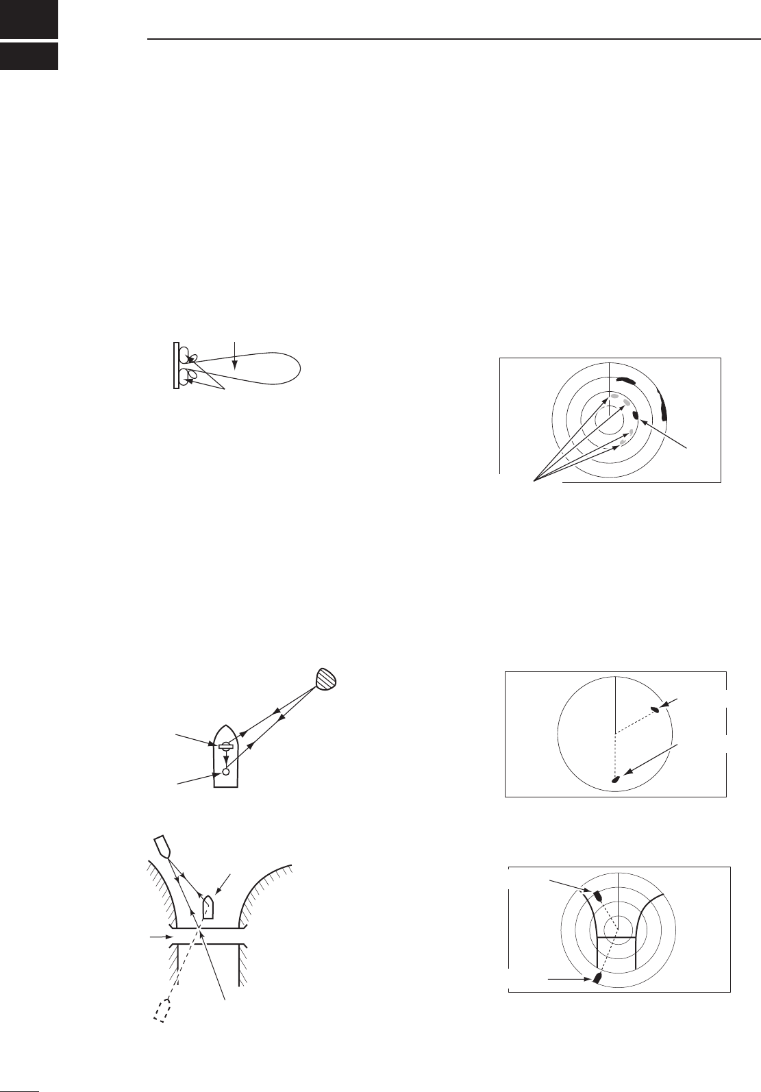
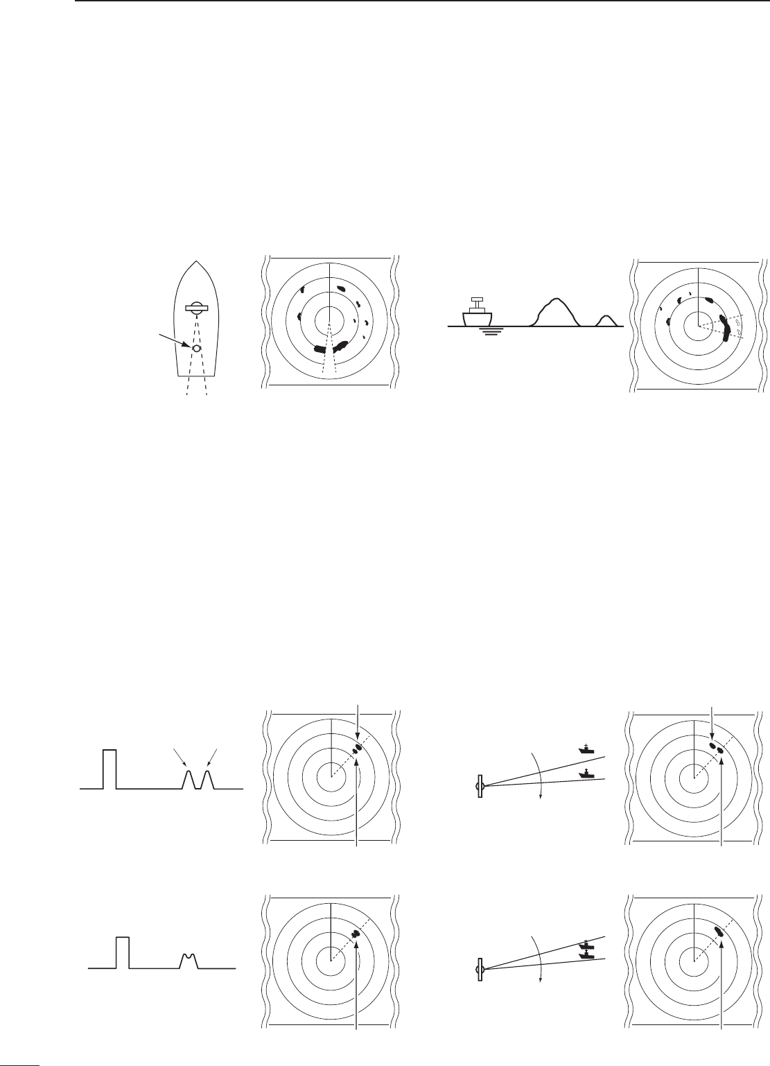
■Indirectechoes
Indirect echoes may be returned from either a
passing ship, or returned from a reflecting surface,
such as a mast on your own ship.
An indirect echo from a reflecting surface will appear
on a different bearing from the direct (true) echo, but
the distance will be approximately the same for both.
■Side-lobeechoes
Radiation can escape on each side of the beam
inside the lobes. If a target reflects this radiation, it will
be displayed on the screen as an echo.
Side-lobe echoes usually occur at short ranges and
as a result of large (strongly reflective) targets. They
canbereducedwithproperadjustmentofthe[SEA]
control.
Radarusesaformofelectromagneticradiation,whichlikelight,canbereected.Becauseofthisproperty,some
objects may cause false echoes on the screen where in fact no targets actually exist.
These echoes may appear if a large vessel, bridge, or tank is in proximity. Operators should be familiar with the
effects of these phenomena. In some cases, echoes can be reduced.
Indirect echo
Tr ue echo
Target
Scanner
Mast or
similar obstruction
An echo is reflected at this point.
Own ship
Target
Bridge
Main beam
Side lobes
Tr ue echo
False echo
False
echoes
Tr ue
echo
MXR-5000T / Page 13-2-14
13
5
BASICRADARTHEORY
■Multipleechoes
Multiple echoes may appear when a short-range
and strong echo is received from a ship, bridge, or
breakwater.
Multiple echoes will appear beyond the target’s true
echo point on the same bearing of a large target.
They can be reduced with proper adjustment of the
[SEA]control.
■Minimumrange
Detection at short range is very important. Minimum
range is determined primarily by transmitter pulse
length, vertical beam width and height of the scanner
unit. The shorter the transmission time, the quicker
the return echoes can be received and their distance
measured.
The ability to see targets very close to the ship is
decreased if the scanner is mounted too high off the
water, because the bottom of the vertical beam of the
scanner cuts off nearby targets.
This target can not be recognized with radar.
The target in this area can not be recognized.
Pulse length
Pulse starting point
Vertical beam width
Own ship Another ship
Tr ue echo
False echoes
1
2
3
4
5
6
7
8
9
10
11
12
13
14
15
16
17
18
19
20
21
MXR-5000T / Page 13-2-15
14
5BASICRADARTHEORY
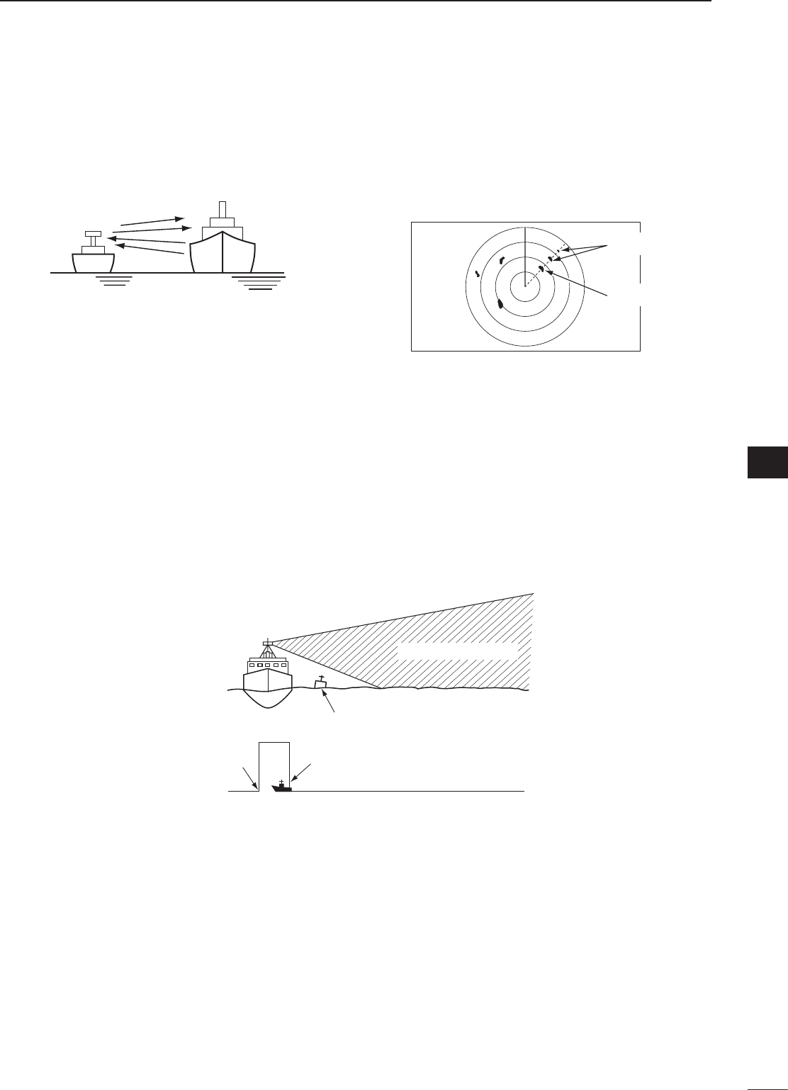
■BlindandShadowsectors
BlindorShadowsectorsmayexistbecauseof
obstructions such as masts, derricks or stacks. An
obstruction may throw either a complete or partial
shadow as shown in the diagram below. If a target is
in a shadow sector, target echoes may not appear on
the screen.
When tall and massive targets such as a large island
are located at close range also shadowed without
producing any echoes. This phenomenon is called
blind sector. It is very important to know the bearings
and widths of all shadow sectors caused by your own
ship’s obstructions.
■Targetresolution
Target resolution is determined by the horizontal
beam width and transmit pulse width. Sometimes it is
difficult to detect two targets which are separated by
short distances or which are in the same direction.
DDistanceresolution
When two targets are separated by more than the
pulse width, they appear as two echoes.
When two targets are not separated by more than
the pulse width, they appear as 1 echo.
Transmit
pulse
Echoes
Target 1 Target 2
Target 2
Target 1
DDirectionresolution
When two targets are separated by more than the
horizontal beam width, they appear as two echoes.
When two targets are not separated by more than
the horizontal beam width, they appear as one
echo.
Scanner
Target 2
Target 1
Target 1, 2
Mast or
similar
obstruction
Shadow sector
Blind sector
Own ship Large
island
Small
island
Target 2
Target 1
Scanner
Target 2
Target 1
Transmit
pulse
Echo
Target 1,2
Target 1, 2
MXR-5000T / Page 13-2-16

15
MEMO
1
2
3
4
5
6
7
8
9
10
11
12
13
14
15
16
17
18
19
20
21
MXR-5000T / Page 13-2-17

1-1-32Kamiminami,Hirano-ku,Osaka547-0003,Japan
A-6????-1EX
Printed in Japan
© 2010 Icom Inc.
MXR-5000T / Page 13-2-18