ICOM orporated 271400 Marine Radar User Manual MR 1000T2 R2 Instruction Manual
ICOM Incorporated Marine Radar MR 1000T2 R2 Instruction Manual
Contents
- 1. Manual
- 2. User Manual
Manual
INSTRUCTION MANUAL
MARINE RADAR
MR-1000R™
(Radome type)
MR-1000T™
(Open array type)
This device complies with Part 15 of the FCC Rules. Opera-
tion is subject to the condition that this device does not cause
harmful interference.
MR-1000R2_T2_FCC.qxd 05.5.17 9:18 Page 1

i
•EX-2714 (Radome type unit)
Qty.
qSystem cable (OPC-1188: 15 m) ......................... 1
wInstallation bolts (M10×50) .................................. 4
eInstallation bolts (M10×25) .................................. 4
rInstallation nuts (M10) ......................................... 4
tFlat washers (M10) .............................................. 4
ySpring washers (M10) ......................................... 4
•EX-2780 (Open array type unit)
Qty.
qSystem cable (OPC-1189: 20 m).......................... 1
wInstallation bolts (M10×40) .................................. 4
eInstallation nuts (M10) ......................................... 4
rFlat washers (M10) .............................................. 4
tSpring washers (M10) ......................................... 4
yHex head wrench ................................................. 1
uCap bolts (M8×18) ............................................... 4
iDish washers (M8) ............................................... 4
oSealing washers (T) ............................................. 4
!0 Flat washers (M8) ................................................ 4
!1 Grounding terminal (R5.5-10) .............................. 1
!2 Ferrite bead ......................................................... 1
•SX-2713/2779 (10 inch CRT display unit)
Qty.
qNMEA connector (FM14-8P) ................................ 1
wSpare fuse (FGB 10 A) ........................................ 1
eSpare fuse (FGB 5 A: for over 24 V power supply)
............................................................................ 1
rDC power cable (OPC-928-1) .............................. 1
tViewing hood (2363 HOOD)................................. 1
yMounting bracket (2363 ANGLE(A))..................... 1
uMounting screw knobs (2363 KNOB BOLT) ......... 2
iSelf-tapping screws (M6 ×30).............................. 5
oSpring washers (M6) ........................................... 5
!0 Flat washers (M6) ................................................ 5
!1 Instruction manual ............................................... 1
!2 Operating guide ................................................... 1
!3 NMEA connector (FM14-7P) ............................... 1
SYSTEM COMPONENTS
SUPPLIED ACCESSORIES
Icom, Icom Inc. and logo are registered trademarks of Icom Incorporated (Japan) in the United states, the
United Kingdom, Germany, France, Spain, Russia and/or other countries.
MODEL NAME CRT DISPLAY SCANNER UNIT
MR-1000RII SX-2713 (10-inch CRT) EX-2714 (Radome type)
MR-1000TII SX-2779 (10-inch CRT) EX-2780 (Open array type)
MR-1000R2_T2_FCC.qxd 05.5.17 9:18 Page 2

ii
FOREWORD
Thank you for purchasing Icom’s MR-1000RII/TII MA-
RINE RADAR.
The radar is designed especially for fishing boats. It
has powerful transmission power, 10 inch CRT display
and many other advanced features.
If you have any questions regarding the operation of
the radar, contact your nearest authorized Icom Inc.
dealer.
IMPORTANT
READ ALL INSTRUCTIONS carefully and com-
pletely before attempting to operate the marine radar.
SAVE THIS INSTRUCTION MANUAL. This
manual contains important safety and operating in-
structions for the MR-1000RII/TII.
EXPLICIT DEFINITIONS
The following explicit definitions apply to this instruc-
tion manual.
PRECAUTION
RNEVER let metal, wire or other objects touch any
internal part of the radar.
RNEVER place the radar within the reach of chil-
dren.
RNEVER expose the display unit to rain, salt water
or any other liquids.
NEVER connect the radar to AC or more than 42 V
DC. This will damage the radar.
AVOID using the radar near any magnetic materials,
such as a loudspeaker or a large power transformer,
as this can cause distortion of the CRT display.
AVOID placing the display unit in excessively dusty en-
vironments.
AVOID placing the display unit near heating equipment
or in direct sunlight or where hot or cold air blows di-
rectly onto it.
AVOID using the scanner unit in areas where the tem-
perature is below –25˚C (–13˚F) or above +70˚C
(+158˚F). AVOID using the display unit in areas where
the temperature is below –15˚C (+5˚F) or above +55˚C
(+131˚F).
AVOID using strong solvents such as benzene or al-
cohol for cleaning the radar, as they may damage the
surfaces.
BE CAREFUL!
SART signal may not be detected and may
not be displayed on the screen depending
on the SEA, RAIN or IR settings.
Follow the settings as below to detect the
SART signal on the screen.
qSelect the screen range between 6 NM
to 12 NM with [+/–]. (p. 2)
wSet the [GAIN] as high as possible. (p. 3)
eSet the [SEA] to minimum. (p. 3)
rSet the [RAIN] to minimum. (p. 3)
tTurn the [IR] OFF.
yTurn the [STRETCH] OFF.
WORD
R
WARNING
CAUTION
NOTE
DEFINITION
Personal injury, fire hazard or electric
shock may occur.
Equipment damage may occur.
If disregarded, inconvenience only.
No risk of personal injury, fire or
electric shock.
MR-1000R2_T2_FCC.qxd 05.5.17 9:18 Page 3

iii
SYSTEM COMPONENTS.......................................... i
SUPPLIED ACCESSORIES....................................... i
FOREWORD ............................................................ ii
IMPORTANT ............................................................. ii
EXPLICIT DEFINITIONS .......................................... ii
PRECAUTION .......................................................... ii
TABLE OF CONTENTS ........................................... iii
1 CAUTION ............................................................. 1
DANGER! HIGH VOLTAGE .................................. 1
RADIATION HAZARD ........................................... 1
2 PANEL DESCRIPTION .................................... 2–5
■Front panel ........................................................ 2
■Screen ............................................................... 4
3 MENU ............................................................... 6–7
■VIDEO ............................................................... 6
■FUNCTION......................................................... 6
■ATA (Automatic Tracking Aid) ............................. 7
■INT. SETTING .................................................... 7
4 BASIC OPERATION ...................................... 8–13
■Checking the installation ................................... 8
■Turning power ON/OFF ...................................... 8
■Basic operation .................................................. 9
■RAIN function ................................................... 10
■SEA function..................................................... 10
■OFF CENTER function..................................... 10
■IR function ........................................................ 11
■STRETCH function .......................................... 11
■ZOOM function ................................................ 11
■TRAILS function .............................................. 12
■Power save function ........................................ 12
■Ship speed indication ...................................... 13
■Position indication ........................................... 13
■Waypoint indication .......................................... 13
■Long pulse function .......................................... 13
■Bearing setting ................................................ 13
5 DISTANCE AND DIRECTION
MEASUREMENTS ....................................... 14–16
■Distance measurement ................................... 14
■Bearing and Distance measurement ............... 15
■Advanced measurements ................................ 16
6 ALARM FUNCTION ........................................... 17
■Alarm zone setting ........................................... 17
■Zone alarm setting ........................................... 17
7 ATA (Automatic Tracking Aid) ................... 18–20
■ATA (Automatic Tracking Aid) .......................... 18
■ATA menu setting ............................................. 18
■ATA operation .................................................. 19
■Plotting marks .................................................. 19
■Course and speed vector ................................ 19
■Plots ................................................................ 20
8 BASIC RADAR THEORY ............................ 21–23
■Side-lobe echoes ............................................. 21
■Indirect echoes ................................................ 21
■Multiple echoes ............................................... 22
■Minimum range ................................................ 22
■Blind and Shadow sectors ............................... 23
■Target resolution............................................... 23
9 INSTALLATION AND CONNECTIONS ........ 24–30
■Connecting the units ........................................ 24
■Power source requirement .............................. 24
■Ground connection ........................................... 24
■Installing the display unit ................................. 25
■Mounting the EX-2714 scanner unit ................ 26
■Wiring the EX-2714 system cable ................... 27
■Mounting the EX-2780 scanner unit ................ 28
■Wiring the EX-2780 system cable ................... 29
■Fixing the EX-2780 scanner unit ..................... 30
10 OTHER FUNCTIONS ...................................... 31
11 SERVICE MAN MENU ............................... 32–34
■Service man menu .......................................... 32
■Select the language ......................................... 32
■TIMING adjustment ......................................... 33
■HDG adjustment............................................... 33
■SPD adjustment ............................................... 34
■RANGE selection ............................................. 34
12 ERROR MESSAGE ......................................... 35
■Error message list ........................................... 35
13 MAINTENANCE ............................................... 36
■Periodic maintenance ...................................... 36
■Scanner unit maintenance ............................... 36
■Display unit maintenance ................................ 36
■Options ............................................................ 36
14 SPECIFICATIONS ..................................... 37–38
15 EXTERNAL DATA LIST ................................... 39
(Supplement) TEMPLATE
■Template for the display unit
•SX-2713/2779 (Display mount bracket template)
■Template for the scanner unit
•EX-2714
•EX-2780
TABLE OF CONTENTS
MR-1000R2_T2_FCC.qxd 05.5.17 9:18 Page 4

1
1
CAUTION
The MR-1000RII/TII are supplemental aids to navigation and are not intended to be a substi-
tute for accurate and current nautical charts.
DANGER! HIGH VOLTAGE
RADIATION HAZARD
Radiation emitted from the scanner unit can be harmful, particularly to the eyes. To avoid harm-
ful radiation, ensure the radar power is in the OFF position before beginning work on the scan-
ner unit.
• NEVER OPEN THE UNIT
This product contains high voltage that could be FATAL. This product has no user-service-
able parts inside. All repairs and adjustments MUST be made by a qualified electronics tech-
nician at your Marine Navigation Dealer.
• HIGH VOLTAGE
High voltages of up to 3,500 volts are used in this equipment. Although prudent measures for
safety have been adopted, sufficient care must be taken in the operation, maintenance and
adjustment of the equipment.
Electric shock of 1,000 volts or more may cause electrocution and death; even an electric
shock of only 100 volts may be fatal.
• PREVENTION OF ELECTRIC SHOCK
(FOR QUALIFIED ELECTRONIC TECHNICIANS ONLY)
To prevent such accidents, turn OFF the power source and do not reach inside the unit until
you have:
q discharged the capacitors by disconnecting the power cable from the power source for
5 min.;
w checked that no electric charges remain inside the device.
Also, it is safest to wear dry insulated rubber gloves. NEVER use both hands simultaneously;
keep one hand in your pocket.
MR-1000R2_T2_FCC.qxd 05.5.17 9:18 Page 1
2
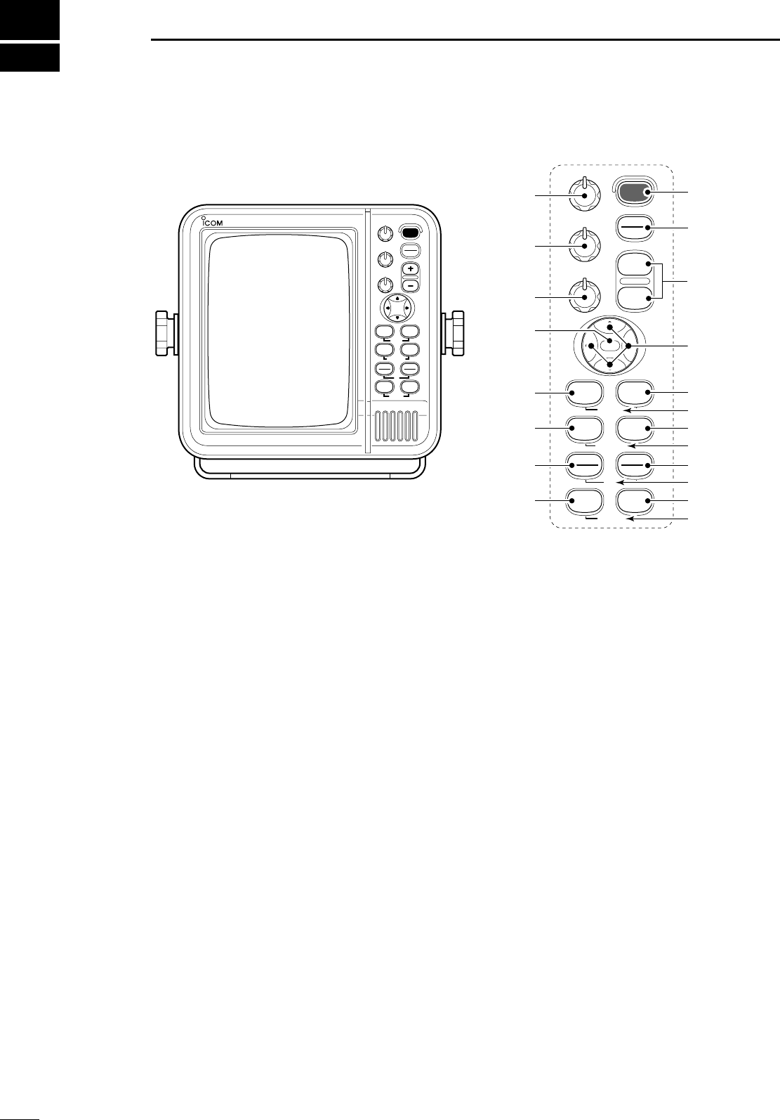
PANEL DESCRIPTION
2
■Front panel
qPOWER SWITCH [POWER] (p. 8)
Turns power ON and OFF.
•The standby screen appears for 90 sec. while warming
up the magnetron.
• The initial screen appears with a beep after the power
has been turned ON.
wTRANSMIT/SAVE SWITCH [TX (SAVE)]
➥Push to toggle between the TX mode and the
standby mode. (p. 9)
➥Push and hold for 1 sec. to turn the power save
function ON. The radar for TX interval scan is
fixed at 10 revolutions. (p. 12)
•Select the save time in INT. SETTING menu.
eRANGE UP/ DOWN SWITCHES [+]/[–] (p. 9)
Push [+] to increase the screen range.
Push [–] to decrease the screen range.
rUP, DOWN, LEFT, RIGHT KEYS [ÙÙ ÚÚ ΩΩ≈≈]]
Set the EBLs, VRMs, alarm area, ATA target, etc.
according to the key pushed.
Use the [ÙÙ] [ÚÚ] to select menu item and [ΩΩ] [≈≈] to
set the item.
Using the [ÙÙ ΩΩ]/[ÙÙ ≈≈] or [ÚÚ ΩΩ]/[ÚÚ ≈≈] combination
allows you to move the cross line cursor to the
upper (or lower) left or right.
tTRAILS SWITCH [TRAILS] (p. 12)
Push to toggle the trail function ON and OFF. This is
useful for watching other ship’s tracks, approx. rela-
tive speed etc.
•Trail Time can be set in VIDEO menu.
yZOOM FUNCTION [ZOOM] (p. 11)
Push [TARGET] and [TRAILS] simultaneously to
toggle the ZOOM function ON and OFF. ZOOM
function expands the target to 2 times normal.
•Move the cursor to the target, then turn the function ON.
•The screen zooms around the middle of the cursor and
own ship.
•This function is not available on 1⁄8and 32 NM or above
ranges.
uMODE SWITCH [MODE]
Push to select one of Head-up (H UP), Course-up
(C UP), North-up (N UP) or True motion (TM)
screens.
•The North-up and Course-up screens can be selected
only when a bearing data format is connected. (p. 39)
•TM screen requires bearing data and LOG or position
data. (p. 39)
•TM screen is not available at 32 NM or above range.
iOFF CENTER FUNCTION [OFF CENT] (p. 10)
Push [ALM] and [MODE] simultaneously to turn the
OFF CENTER function ON or OFF.
•This function is available for 24NM or shorter range se-
lection.
MOB
GAIN
SEA
RAIN
POWER
TX
SAVE
TARGET
TRAILS
ZOOM
ALM
MODE
OFF CENT
EBL1
VRM1
PI
BRILL MENU
HL OFF
EBL2
VRM2
MARINE RADAR TX
SAVE
TARGET TRAILS
MODEALM
+
-
MOB
MENU
EBL2
VRM2
EBL1
VRM1
BRILL
ZOOM
OFF CENT
PI
HL OFF
GAIN
SEA
RAIN
POWER
e
r
q
w
t
u
o
!1
y
i
!2
!3
!4
!5
!6
!7
!8
!9
@0
!0
Control panel
MR-1000R2_T2_FCC.qxd 05.5.17 9:18 Page 2

3
2
PANEL DESCRIPTION
o
EBL2 (VRM2) SWITCH [EBL2 (VRM2)] (pgs. 15–16)
Push to display the electronic bearing line 2 (EBL2)
and the variable range marker 2 (VRM2), and acti-
vate the [Ω≈]for the electronic bearing line selec-
tor and [Ù Ú] for the range marker selector.
•When the VRM1 and EBL1 ($9 %2) are displayed, the
center of VRM2 appears at the intersection point of the
VRM1 and EBL1.
!0 PARALLEL INDEX LINE FUNCTION [PI]
Push [EBL1] and [EBL2] simultaneously to toggle
the parallel index line ON and OFF.
•Push [Ω≈] keys to rotate the lines, and push [Ù Ú]
keys to adjust the line spaces.
!1 MENU SWITCH [MENU] (pgs. 6–7)
Push [MENU] to toggle the VIDEO, FUNCTION,
ATA, INT. SETTING and SERVICE MAN menu.
Push [Ù Ú] keys to select the items and push [Ω
≈] keys to change the setting.
!2 HEADING LINE OFF FUNCTION [HL OFF] (p. 9)
Push [BRILL] and [MENU] simultaneously to turn
off the heading line temporarily.
!3 GAIN CONTROL [GAIN] (p. 9)
Adjusts the receiver amplifier gain.
•Clockwise rotation increases the gain
•Increased gain may increase screen noise.
!4 SEA CLUTTER CONTROL [SEA] (p. 10)
This function serves to eliminate echoes from the
waves at close range.
Reduces the receiver gain for close objects within
a radius of 8 nautical miles (approx.) to eliminate
sea clutter.
Rotate the control fully clockwise to activate the au-
tomatic SEA control function. SEA indicator (@6) ap-
pears in the upper left of the screen.
•Under normal conditions set the SEA to a minimum.
•Use this control with caution when the sea is rough.
!5 RAIN CLUTTER CONTROL [RAIN] (p. 10)
This function eliminates reflection echoes from rain,
snow, fog, etc.
Rotate the control fully counter clockwise to deacti-
vate the RAIN function.
RAIN indicator (@8) disappears.
!6 MAN OVERBOARD [MOB]
Push to mark the man overboard point on the
screen. When a crew member falls overboard, push
[MOB] for 1 sec. to display the MOB symbol ( ) on
the screen.
•MOB readout shows the bearing, distance and esti-
mated time to the MOB point with current speed.
•Push [MOB] for 1 sec. to cancel the function.
•Position and bearing data are necessary.
!7 TARGET SWITCH [ATA] (pgs. 18–20)
A setup of target caught by ATA (up to 10 targets
can be set).
•Push [Ù Ú Ω ≈] to move the cross cursor on the echo
which you want to plot on the screen before turning the
function ON.
•Select “ATA” function ON in the “ATA” menu, set the ap-
propriate No. DISP, VECT, OWN VECT, ALARM, CPA
LIMIT and TCPA LIMIT setting.
!8 ALARM SWITCH [ALM] (p. 17)
Push [ALM] to toggle the alarm function ON and
OFF.
Push and hold [ALM] for 1 sec. to enter the alarm
area setting condition.
•Push [Ù Ú Ω ≈] to move the cross cursor to the zone
starting point, then push [ALM] for 1 sec. The starting
ring of the zone is created. Then push [Ù Ú Ω ≈] to fix
the finish point, the desired alarm zone will automatically
form.
!9
EBL1 (VRM1) SWITCH [EBL1 (VRM1)] (pgs. 15–16)
Push to display the electronic bearing line 1 (EBL1)
and the variable range marker 1 (VRM1) and acti-
vate the [Ω≈] for the electronic bearing line selec-
tor, and [ÙÚ] for the range marker selector.
•EBL1 bearing and VRM1 distance are displayed, in the
bottom window.
•When EBL1 and VRM1 are displayed, the beginning of
EBL2 appears at the intersection point of EBL1 and
VRM1.
@0 DISPLAY BRILLIANCE SWITCH [BRILL] (p. 9)
➥Push to increase or decrease the brilliance of the
picture on the display.
➥Push for 1 sec. to select the maximum brilliance.
•The brightness of the symbol, character and illumi-
nation can be adjusted in the “SYMBOL”, “CHAR-
ACTER” and “KEY ILLUM” of the INT. SETTING
menu independently.
MR-1000R2_T2_FCC.qxd 05.5.17 9:18 Page 3
4
2PANEL DESCRIPTION
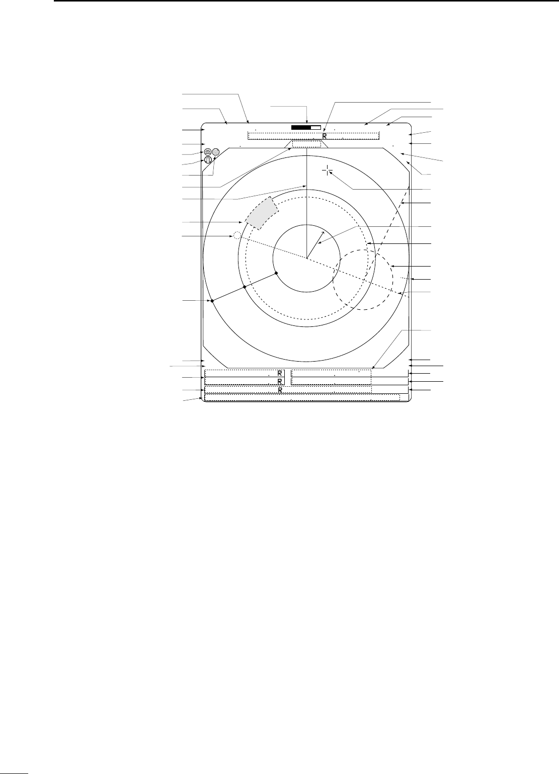
■Screen
@1 TUNING LEVEL INDICATOR (p. 9)
Shows the receiver tuning level.
@2 TUNING MODE INDICATOR (p. 9)
“M.TUNE”appears when the manual tuning func-
tion is in use.
@3 FIXED RING RANGE READOUT (p. 14)
Shows the interval range of the fixed ring.
•This readout appears when the “RING”of the FUNC-
TION menu is turned ON.
@4 SCREEN RANGE READOUT (p. 14)
Shows the maximum range of the displayed screen.
•The range indicated is nautical miles (NM).
@5 SHIP SPEED READOUT (p. 13)
Shows the ship speed.
•SOG: When GPS is selected in the INT. SETTING
menu.
•STW: When LOG is selected in the INT. SETTING
menu.
@6 AUTO SEA INDICATOR (p. 10)
Appears when the automatic SEA control function
is turned ON.
@7 LONG PULSE INDICATOR (p. 13)
Appears when the long pulse is in use.
@8 RAIN CONTROL INDICATOR (p. 10)
Appears when the RAIN function is in use.
@9 MODE INDICATOR
Head-up, Course-up, North-up and True Motion
screens are available.
•N UP and C UP screens require external bearing data.
(p. 39)
•TM screen requires bearing data and LOG or position
data.
#0 HEADING LINE (p. 9)
Heading line indicates the ships bow.
#1 ALARM ZONE (p. 17)
Shows the alarm zone.
•Appears when the alarm function is in use.
#2 WAYPOINT MARKER (p. 13)
Shows the waypoint received from navigation
equipment.
•This marker appears when the “WPT” of the FUNCTION
menu is turned ON.
•To display the waypoint marker, bearing data and NMEA
data with 0183 format is necessary. (p. 39)
#3 FIXED RANGE RINGS (p. 14)
Shows the distance in fixed intervals. The interval
distance is indicated by the ring range readout (@3).
•These rings appear when the “RING” of the FUNCTION
is turned ON.
#4 GPS indicator (p. 24)
Indicator appears when the GPS or DGPS receiver
is connected.
:
:
:
:
(0.25)
MTUNE TVECT 6M
0649NM
NM CURS
STW157KT H UP
0174
˚
R
TRAILS
HDG2530
˚T
IR
EBL1 1076
˚
R
EBL2 0219
˚
R
WPT 2834
˚
R
VRM1 0422NM 001
000
001
VRM2 0242NM
0632NM
CURS 34
˚
39720N 135
˚
34420E
ZOOM
ALM
COMPASS
GPS
ES
005
M.TUNE
3/4
@1
@2
@3
@4
@5
@6
@7
@8
@9
#0
#1
#2
#3
#4
#5
#6
#7
#8
#9 $0
$1
$2
$3
$4
$5
$6
$7
$8
$9
%0
%1
%2
%3
%4 %5
%6 %7
%8
MR-1000R2_T2_FCC.qxd 05.5.17 9:18 Page 4

5
2
PANEL DESCRIPTION
#5 COMPASS INDICATOR (pgs. 24, 39)
•GYRO : NMEA (gyro) is connected.
•COMPASS : NMEA (compass), N+1 or AUX data is
connected.
#6 EBL1/ 2 READOUTS (pgs. 15–16)
Shows the bearing of the displayed Electronic Bear-
ing Lines (EBL1 and EBL2) when the EBL is in use.
•EBL2 shows PI (!0) readout.
#7 WAYPOINT/MOB READOUTS (p. 13)
➥Shows the bearing and distance to the waypoint
received from navigation equipment.
•This readout appears when the “WPT” of the FUNC-
TION menu is turned ON.
•To display the waypoint/MOB marker, bearing data
and NMEA data with 0183 format is necessary.
(p. 39)
➥Shows the bearing and distance to the MOB
(Man Over Board) event marker.
•Push [MOB] to cancel the readout and the symbol.
#8 POSITION/CURSOR READOUT (p. 13)
Shows your own ship or cursor latitude and longi-
tude readout when external NMEA data with 0183
format is connected.
•Select ‘SHIP’or ‘CURS’in the “POSN DISP” of the
FUNCTION menu.
•To display the POSITION; NMEA 0183 is necessary.
•To display the CURSOR; NMEA 0183 and bearing data
are necessary.
#9 CURSOR INDICATOR
Shows the bearing and distance to the cursor.
$0 VECTOR INDICATOR (p. 18)
Shows the ATA and OWN vector type.
•T: True vector
•R: Relative vector
$1 VECTOR TIME INDICATOR (p. 18)
Shows the vector interval time. Select vector time
in the “TRAIL TIME” of the VIDEO menu.
•30 min. is applied, when ‘∞’is selected for the vector
time.
$2 TRAILS INDICATOR (p. 12)
Shows the trail time.
•Echo remains with gradation during the trail time period
on the screen. (Except for the trail time; ∞)
•Progressing time counter starts to count the time until
the timer reaches the trail time.
$3 HEADING INDICATOR
Shows the heading bearing readout.
•The HDG readout indicates the bow of the ship’s bearing
in a clockwise direction from north.
$4 IR INDICATOR (p. 11)
Eliminates or reduces interference caused by other
radar operating nearby.
•This function is available when the “IR” in the VIDEO
menu is set to 1 or 2.
$5 ECHO STRETCH INDICATOR (p. 6)
Appears when the echo stretch function is in use.
•This function is available when the “STRETCH” of the
VIDEO menu is turned ON.
$6 CROSS LINE CURSOR
Used for measuring the bearing and distance, set-
ting the alarm zone, selecting the ATA targets, etc.
• Push [Ù Ú Ω ≈] several times to move the cursor.
$7 EBL2 (pgs. 15–16)
Used for bearing measurement. When a target is
selected, the EBL readout (#6) shows the bearing.
$8 OWN SHIP VECTOR INDICATOR
Shows the vector of your own ship.
$9 VRM 1 (pgs. 15–16)
%0 VRM 2 (pgs. 15–16)
Used for distance measurement. When a target is
selected, the VRM1/2 readout (%3) shows the dis-
tance.
%1 NORTH MARK
The north mark shows the true north direction.
%2 EBL1 (pgs. 15–16)
Used for bearing measurement. When a target is
selected, the EBL readout (#6) shows the bearing.
%3 VRM1/2 READOUTS (pgs. 15–16)
Shows the distance of the displayed Variable Range
Markers (VRM1 and VRM2) when the VRM is in
use.
•Nautical miles (NM) and kilometers (KM) can be se-
lected in the FUNCTION menu as the distance unit.
%4 ALARM INDICATOR (p. 17)
Appears when the alarm function is in use.
%5 ZOOM INDICATOR (p. 11)
Appears when the zoom function is in use.
•Push [TARGET] and [TRAILS] simultaneously to turn
the function ON or OFF.
%6 TIME INDICATOR
%7 TIME INDICATOR
Shows the estimated time to the marker edge from
center of the marker with current speed.
%8 TIME INDICATOR
Shows the estimated time to the waypoint with cur-
rent speed.
MR-1000R2_T2_FCC.qxd 05.5.17 9:18 Page 5

3
6
MENU
■VIDEO
DTUNE
•AUTO : Automatic tuning.
•“A.TUNE” appears for approx. 2 sec. instead
of the screen display, when first transmitting
after turning the power ON. The unit also re-
tunes in some cases.
•MANUAL : Manual tuning.
Push [≈] to select [MANUAL] then push
[Ú] to activate the manual tuning slider.
Push [Ω ≈] to adjust desired tuning level.
DD.RANGE
Select the dynamic range of the PPI (Plan Position In-
dicator).
•NAR. : Narrow dynamic range. Even weak re-
flections are displayed as strong reflec-
tions.
•MID. : Mid dynamic range.
•WIDE : Wide dynamic range. You can distinguish
between weak reflections and strong re-
flections easily.
DIR
•OFF : Turn the Interference Reduction function
OFF.
•
1 or 2 (ON)
: Turn the Interference Reduction function
1 (Low) or 2 (High).
DSTRETCH
•OFF : Turn the echo stretch function OFF.
•ON : Turn the echo stretch function ON.
DPULSE
•SP : Select the short pulse.
•LP :Select the long pulse. LP indicator ap-
pears on the screen.
DSEA
•The characteristic (curve) of a SEA knob can be cho-
sen as the optimal characteristic out of four kinds with
the height of an antenna.
DTRAIL TIME
•6S,15S, 30S, 1M, 3M, 6M, 15M or ∞:
Select the plot interval and vector time.
■FUNCTION
DRING
•OFF : Turn the fixed range ring display OFF.
•ON : Turn the fixed range ring display ON.
DWPT
•OFF :Non display the way point on the screen.
•ON : Display the way point on the screen.
DPOSN DISP
•SHIP: : Display your own ship’s position.*
•CURS : Display the cursor position.**
* External latitude/longitude data required.
** External latitude/longitude data and bearing data required.
DDIST UNIT
•NM : Display the distance unit in Nautical Mile.
•KM : Display the distance unit in Kilometer.
DBRG
Select the displayed bearing type, no relation with the
bearing data format (NMEA, N+1 or AUX).
•TRUE : Select the true bearing.
•MAG :Select the magnetic bearing.
DEBL/PI (except HDG and CSE) (p. 15)
•TRUE : True or magnetic direction.
•360°R : Relative direction
•PT/SB : Bow direction
DZONE ALARM
•IN : Alarm is emitted when the target comes into
the zone.
•OUT : Alarm is emitted when the target goes out
of the zone.
DBEEP
•OFF : Turn the beep tone OFF*.
•ON : Turn the beep tone ON.
* Except alarm function.
FUNCTIONMENU
POSN DISP
WPT ON
DIST UNIT
BRG
EBL/PI
ZONE ALARM
BEEP
MAG
PT/SB
KM
OUT
ON
OFF
CURS
NM
TRUE
TRUE
IN
RING
OFF ON
OFF
SHIP
360˚R
VIDEO MENU
D.RANGE
IR
STRETCH
PULSE
SEA
TRAIL TIME
ON
12
LP
MANUAL
AUTO
MID. WIDE
OFF
OFF
SP
6S
3M
15S
6M
30S
15M
1M
TUNE
1234
NAR.
MR-1000R2_T2_FCC.qxd 05.5.17 9:18 Page 6

7
3
MENU
■ATA (Automatic Tracking Aid)
DATA
•OFF : Turn the ATA function OFF.
•ON : Turn the ATA function ON.
DNo.DISP
•OFF : Non display any mark number.
•Sel :Display the selected mark number
only.
•ALL : Display all mark numbers.
DVECT
•TRUE : Select the true vector mode.
•REL : Select the relative vector mode.
DOWN VECT
•OFF : Non display the own ship vector.
•ON : Display your own ship’s vector.
DALARM (CPA/TCPA)
•OFF : Turn the alarm function OFF.
•ON : Turn the alarm function ON.
DCPA* LIMIT
•0.1 to 10.0NM : Set the CPA (Closest Point of Ap-
proach) limit with [Ω≈
].
DTCPA* LIMIT
•1 to 60MIN : Set the TCPA (Time to CPA) limit time
with [Ω≈
].
*CPA/TCPA: Closest Point of Approach and Time to Clos-
est Point of Approach limit is defined by the observer to
given warning when a target or targets are close to
within those limits from your own ship.
■INT. SETTING
DMAG VAR
•AUTO : Revise magnetic variation automatically.
NOTE: NMEA data is required. NEVER select
“AUTO” without NMEA data, incorrect varia-
tion data may entered. (p. 39)
•MANUAL : Revise magnetic variation manually.
•Push [≈]to select [MANUAL], then push
[Ú]. Set the revise value with [Ω≈
].
Push [Ú] or [MENU] to abort the menu.
DBRG INPUT
•NMEA : NMEA0183 bearing data format.
•N+1 : N+1 data format.
•AUX :Other format.
•GPS : Reads NMEA0183 COG format data as
HDG format.
DSPD INPUT
•GPS : Use the GPS NMEA speed data.
•LOG : Use the speed sensor data.
DTX INH START
•0 to 359°:Push [Ω≈
]to enter the start point of the
TX inhibit area.
DTX INH ANGLE
•0 to 90°:Push [Ω≈
]to enter the TX inhibit area.
DSAVE TIME
•1M, 6M, 15M or 30M
: Select the stand by time during save
mode.
* The radar for TX interval scan is fixed at 10 revolutions.
DSYMBOL
•1/2/3 : Select the symbol brightness.
DCHARACTER
•1/2/3 : Select the character brightness.
DKEY ILLUM
•1/2/3/4 : Select the key illumination brightness.
INT. SETTING
BRG INPUT
SPD INPUT
TX INH START
TX INH ANGLE
SAVE TIME
SYMBOL
CHARACTER BRILL
NMEA
30M
LOG
6M 15M
MANUAL
AUTO
N+1 AUX GPS
GPS
0
˚
0
˚
KEY ILLUM
MAG VAR
123
123
1234
7.2
˚
W
1M
ATA MENU
VECT
No.DISP OFF ALL
OWN VECT
ALARM
CPA LIMIT
TCPA LIMIT
TRUE
ON
ON
ON
OFF
REL
OFF
OFF
1.0NM
1 MIN
ATA
SEL
MR-1000R2_T2_FCC.qxd 05.5.17 9:18 Page 7
BASIC OPERATION
4
8
■Checking the installation
Before turning the power ON, be sure all the connec-
tions are complete. The checklist at right may be help-
ful for necessary confirmation.
DChecklist
qThe 4 bolts securing the scanner unit must be firmly
tightened.
wCabling must be securely attached to a mast or
mounting material, and must not interfere with the
rigging.
eBe sure waterproofing procedures are completed
on the system cable.
rThe power connections to the battery must be of the
correct polarity.
tBe sure that the plugs at the rear of the display unit
have been connected correctly and securely.
(See p. 24 for details.)
CAUTION: Connect the scanner unit before turning the
power ON. Otherwise the magnetron inside the scanner
unit might be damaged.
■Turning power ON/OFF
qPush [POWER] to turn the power ON.
•The initial screen appears and warming up time is
counted down on the screen.
•
The magnetron inside the scanner unit warms up for 90 sec.
•[POWER] does not function for 2 sec. after the power is
turned OFF.
wWhen the countdown is completed, the Standby
screen appears.
ePush [TX] to start scanning and select the Plan Po-
sition Indicator (PPI) screen.
•Targets and heading marker appear.
•The screen appears approx. 2 sec. after turning the
power on, when ‘AUTO’is selected in the “TUNE” of the
VIDEO menu.
rPush [POWER] to turn the power OFF.
1
(0.25)
T.VECT 6M
0.000NM
NM CURS
SOG17.7KT H UP
000.0˚T
HDG253.4˚T
EBL1
EBL2
MOB
VRM1
VRM2
CURS 34 ˚ 37.72N 13 5˚ 34.42E
STBY
IR
COMPASS
GPS
1
(0.25)
T.VECT 6M
0.000NM
NM CURS
SOG17.7KT H UP
000.0˚T
HDG253.4˚T
EBL1
EBL2
MOB
VRM1
VRM2
CURS 34 ˚ 37.72N 13 5˚ 34.42E
IR
COMPASS
GPS
0.45
REV *.*
ROM OK
RAM OK
MR-1000R2_T2_FCC.qxd 05.5.17 9:18 Page 8
4
BASIC OPERATION
9
■Basic operation
qTurn the power ON.
wPush [TX] after the countdown disappears from the
screen.
•See “Turning power ON/OFF” on page at left.
ePush [+] or [–] several times to select the display
range.
•The screen range readout shows the maximum range of
the screen.
rTurn [GAIN] to set 1 o’clock position.
•Clockwise rotation increases the gain.
•Increased gain may increase screen noise.
tTurn [SEA] to set the sensitivity time control for min-
imum.
yTurn [RAIN] to set the rain clutter control for mini-
mum.
uPush [MODE] to select one of Head-up;H UP,
Course-up;C UP, North-up;NUP or True Motion;TM
screens.
C UP, N UP or TM can be selected only when bear-
ing, position or speed data are connected.
(See p. 39 for details)
NOTE:
Manual adjustment can be used. (See below.)
TX
SAVE
TARGET TRAILS
MODEALM
+
-
MOB
MENU
EBL2
VRM2
EBL1
VRM1
BRILL
ZOOM
OFF CENT
PI
HL OFF
GAIN
SEA
RAIN
POWER
e
q
w
u
r
t
y
CAUTION: When setting the [SEA] control to a fully clock-
wise position, close targets are blanked.
DHeading marker
The heading marker is a line that shows your ship’s
bow direction. (This marker will appear in the center of
the screen when the Head-up screen H UP is se-
lected.) The heading marker can be hidden when the
desired target is located under the heading marker.
•Push and hold [BRILL] and [MENU] simultaneously to hide
the heading marker.
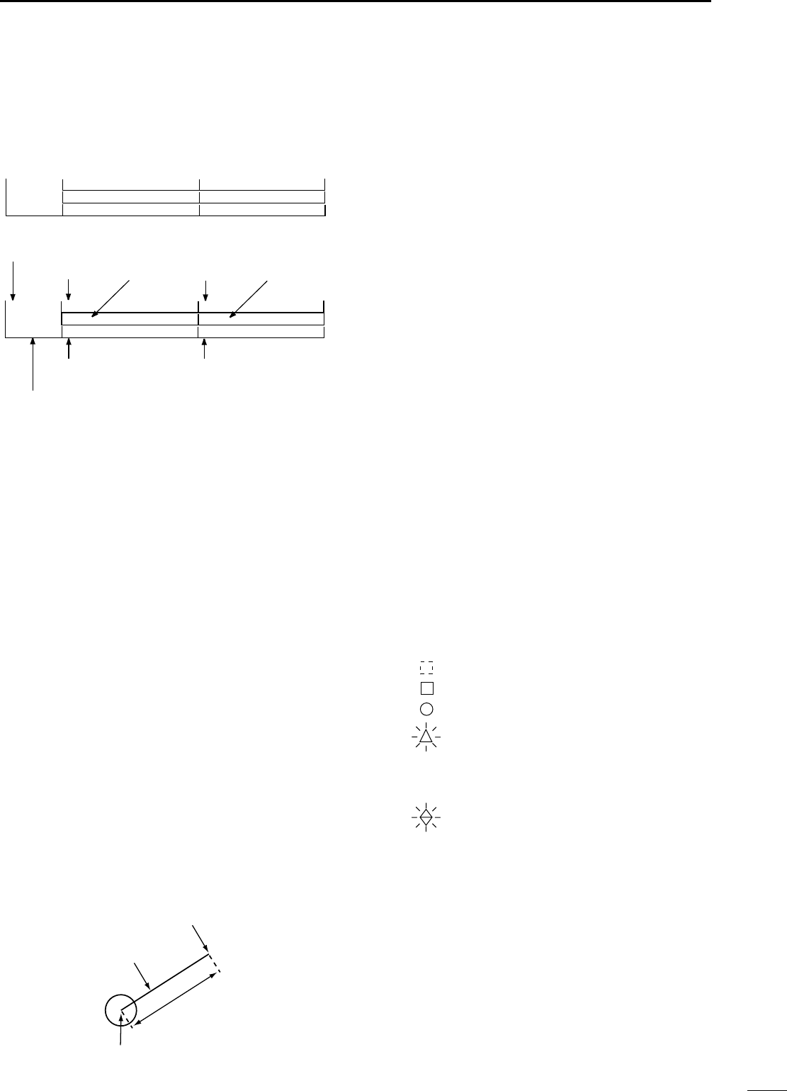
DFixed range rings
The fixed range rings can be used for rough distance
measurement. (p. 14)
Push [MENU] to open the FUNCTION menu, then
push [Ú] to select RING. Push [≈] to turn the ring ON.
DManual tuning
The receiver tuning can be manually adjusted.
Push [MENU] to open the VIDEO menu, then
select MANUAL. Push [Ú] to activate the manual tun-
ing slider, then push [Ω ≈] to set the tuning level indi-
cator to the maximum level. (p. 6)
•“M.TUNE” appears on the top of the display.
DBrilliance adjustment
The intensity of the screen can be adjusted. When you
require continuous operation, but not constant viewing,
a lower setting can increase the life of the CRT display.
• Key illumination
The backlighting of the keys can be adjusted for con-
venient operation. (p. 7)
Push [MENU] four times to call up the INT. SETTING
menu. Push [Ω ≈] to select the illumination level.
•Key illumination corresponds with [BRILL] control.
NOTE: High intensity will shorten the life of the CRT
display.
MR-1000R2_T2_FCC.qxd 05.5.17 9:18 Page 9
10
4BASIC OPERATION
The following are typical basic operation examples, which may hinder radar reception (sea clutter, precipitation in-
terference and echoes from other radar).
■RAIN function
This function eliminates reflection echoes from rain,
snow, fog etc.
•Rotate the control fully counterclockwise to deactivate the
control function. The RAIN indicator ( ) disappears.
•NOTE: DO NOT reduce the reflection echoes too much,
otherwise you may miss weaker targets.
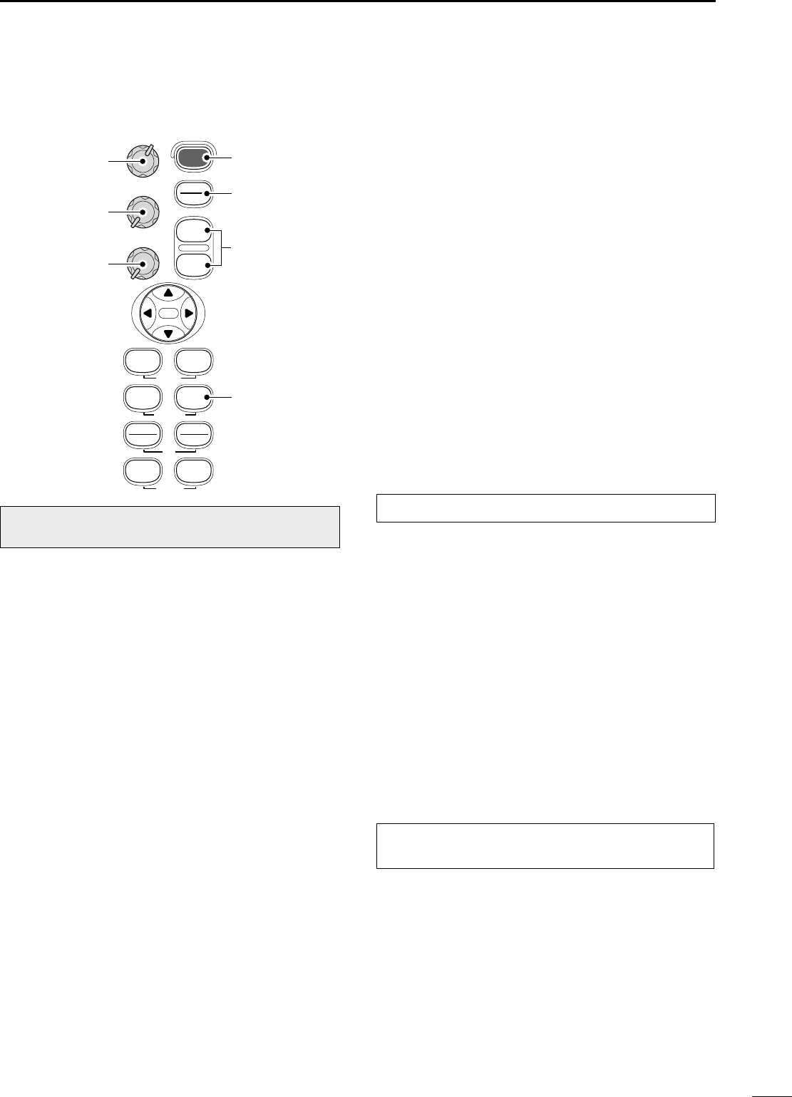
■SEA function
This function serves to eliminate echoes from waves
at close range. Reduce the receiver gain for close ob-
jects within a radius of 8 miles to eliminate sea clutter.
•Rotate the control fully clockwise to activate the automatic
control function. SEA indicator ( )appears in the upper left
of the screen.
■OFF CENTER function
The scanning area can be shifted in a desired direc-
tion and can be enlarged partially. This is useful when
the Head-up* is selected and you want to enlarge the
bow direction display, or, the center of the screen shifts
in the direction of the intersection.
•This function is available for 24NM or shorter range selec-
tion.
*This function is not available in the TM screen.
qPush [Ù Ú Ω ≈] to move the cursor where you
want to shift the center of the screen.
• Max. offsetting is up to 75% of the screen.
wPush [ALM] and [MODE] simultaneously to shift
the screen.
ePush [ALM] and [MODE] simultaneously again to
return to the normal screen.
With OFF CENTER ON
Normal screen
Adjust SEA control
Echos from sea waves
Adjust RAIN control
Small echos
WARNING: The [SEA] control reduces the re-
ceiver sensitivity of objects within 8 miles. Therefore,
caution and careful adjustment are necessary when
using the [SEA] control.
Small objects may not be displayed on the screen
when strong echoes from the rain or the island within
1 NM while automatic SEA function is activating.
MR-1000R2_T2_FCC.qxd 05.5.17 9:18 Page 10
11
4
BASIC OPERATION
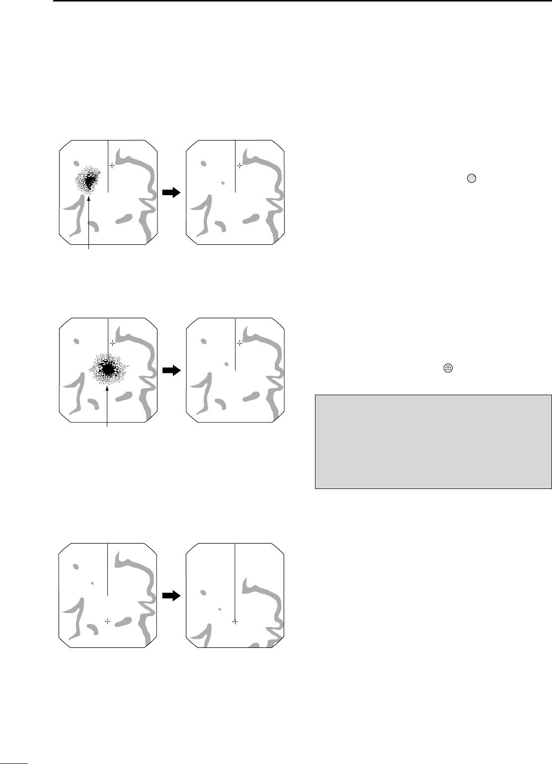
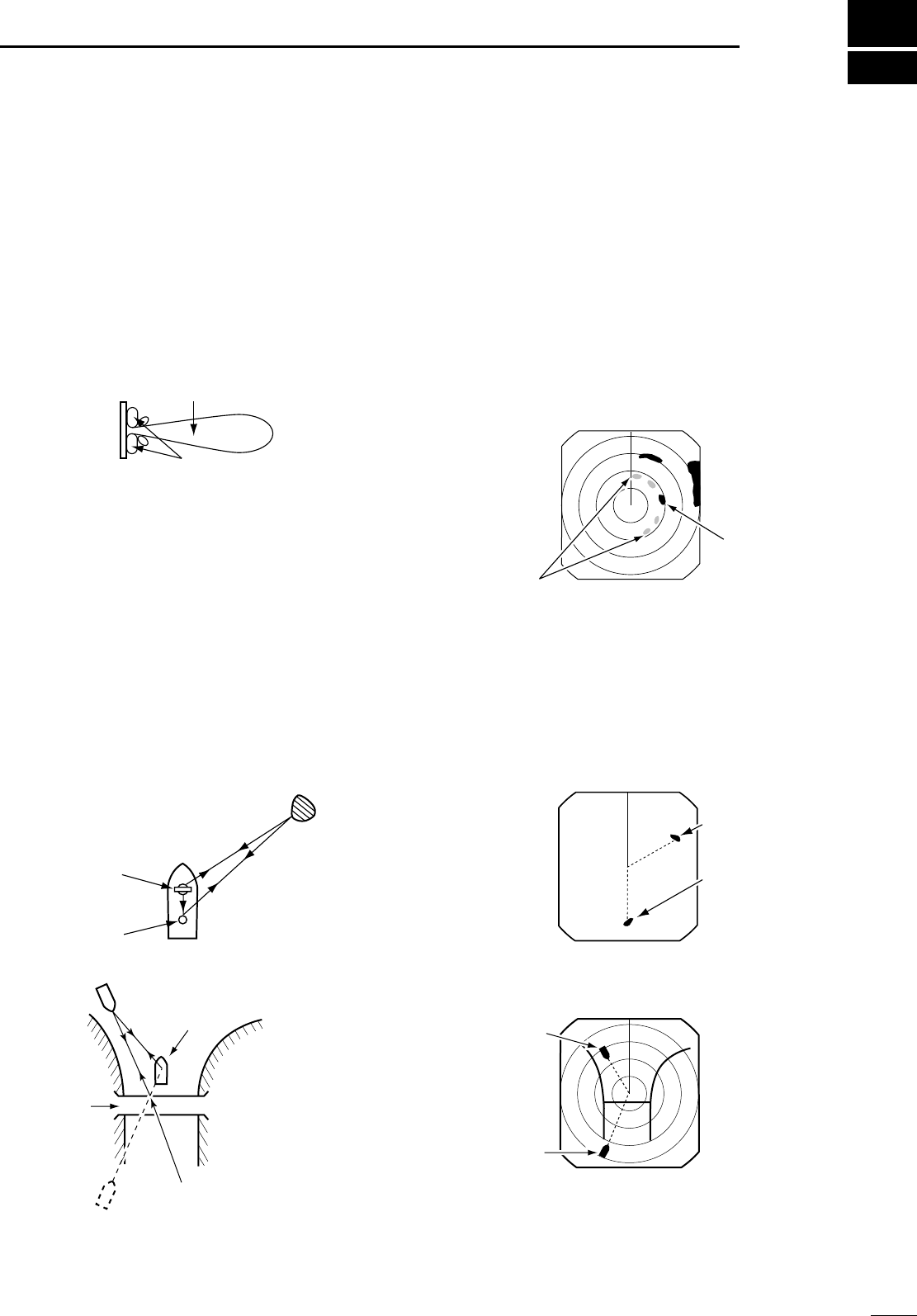
■IR function
Radar interference may appear when another ship’s
radar is operating on the same frequency band in
close proximity. The IR function can eliminate this type
of interference. (p. 6)
qPush [MENU] to call up VIDEO menu.
wPush [Ú] until the “IR” section becomes highlighted.
ePush [Ω ≈] to select IR function 1, 2 or OFF.
•“IR” appears in the upper right of the screen, when the
function is activated.
■STRETCH function
The blips can be magnified electronically for easier
viewing of small targets. (p. 6)
qPush [MENU] to open the VIDEO menu.
wPush [Ú] to select “STRETCH”, then push [≈]to
turn the function ON.
■ZOOM function
The ZOOM function expands the target to two times
normal size.
•This function is available up to a 24 NM range or shorter ex-
cept 1⁄8NM.
qPush [Ù Ú Ω≈] to move the cursor to the desired
target.
wPush [TARGET] and [TRAILS] simultaneously to
toggle the ZOOM function ON and OFF.
•“ZOOM” appears in the lower right of the screen.
With ZOOM function ON
Normal screen
NOTE: Turn OFF this function during normal opera-
tion.
With STRETCH ON
Normal screen
With IR function ON
Radar interference
MR-1000R2_T2_FCC.qxd 05.5.17 9:18 Page 11
12
4BASIC OPERATION
■TRAILS function
The trails function memorizes echoes continuously or
at constant intervals. This is useful for watching other
ships’tracks, approx. relative speed, etc.
• Setting the trail interval time
qPush [MENU] twice to call up the VIDEO menu.
•Push [Ú] several times until the “TRAIL TIME” section
becomes highlighted.
wPush [Ω ≈] to select trail interval time.
•6 sec., 15 sec., 30 sec., 1 min., 3 min., 6 min., 15 min.
and ∞(continuous) are available.
ePush [MENU] several times to exit the menu.
• Using the TRAILS function
qPush [TRAILS] to turn the trail function ON.
•“TRAILS” and trail interval time appears in the upper
right of the screen.
•Trail interval counter starts to count up to the trail time.
wAll displayed echoes at the plotted time are memo-
rized and displayed with a graduated intensity to-
gether with the current echoes.
•Echoes are displayed with minimum intensity when “∞”
is selected.
ePush [TRAILS] to cancel the trail function and erase
the plotted echoes.
•“TRAILS” and trail interval time disappears.
Trail time
3/4
(0.25)
M.TUNE 1:0 5
NM CURS
STW 15.7KT H UP
011.4˚R
HDG 253.9˚T
6M
TRAILS
IR
ES
T.VECT
0.453NM
TRAIL
indicator
Trail interval
counter
Trail time
■Power save function
The power save function conserves the boat’s battery
power by pausing the transmission. The standby
(pausing) times are selectable (rotation number is fixed
to 10).
For example, when 1 min. is selected, the scanner ro-
tates 10 revolutions; then stops for 1 min., and then re-
peats this sequence while the power save function is
activated.
DSetting the scanning standby time
qPush [MENU] four times to call up the INT. SET-
TING menu.
wPush [Ú] until the “SAVE TIME” section becomes
highlighted.
ePush [Ω ≈] to select standby time.
•1, 6, 15, and 30 min. are available.
rPush [MENU] twice to exit the menu display.
DUsing the power save function
qPush and hold [TX (SAVE)] for 1 sec. to turn the
power save function ON.
•The save indicator appears in the top of the screen.
wAfter the scanning rotations are finished, transmis-
sion and rotation are suspended until the selected
standby time elapses.
•The display shows the last scanned echoes until the
scanning restarts.
•“SAVE” and standby time appear in the top of the screen
and the standby time is counted down.
eAfter the selected standby time elapses, transmis-
sion and rotation restart.
rPush [TX (SAVE)] to cancel the power save func-
tion.
•The save indicator turns OFF.
NOTE: When you use the power save function to-
gether with the alarm function, the CRT display is
turned OFF until an object enters the programmed
alarm zone, therefore, more power saving is possi-
ble. (p. 17)
CURS 34˚ 37.72N CURS 34˚ 37.72N
1
(0.25)
T.VECT 6M
0.900NM
NM CURS
SOG17.7KT H UP
014.6˚T
HDG273.9˚T
IR ES
EBL1
EBL2
MOB
VRM1
VRM2
13 5˚ 34.42E
0:48
SAVE
Push and hold [TX] for 1 sec.
to turn the SAVE function on.
Scan and STBY alternates
Count down the standby time
1
(0.25)
T.VECT 6M
0.900NM
NM CURS
SOG17.7KT H UP
014.6˚T
HDG273.9˚T
IR ES
EBL1
EBL2
MOB
VRM1
VRM2
13 5˚ 34.42E
0:00
SAVE
COMPASS
GPS
COMPASS
GPS
MR-1000R2_T2_FCC.qxd 05.5.17 9:18 Page 12

13
4
BASIC OPERATION
■Ship speed indication
When the ship speed data with NMEA 0183 format is
applied, the radar can display the ship speed. Knots
(KT) or kilometers/hour (KM/h) are automatically se-
lected in the normal screen (p. 4) by selecting nautical
miles (NM) or kilometers (KM) respectively.
qPush [MENU] several times to call up the FUNC-
TION menu.
wPush [Ú] until the “DIST UNIT” section becomes
highlighted.
ePush [Ω ≈] to turn the ship speed indication to NM
or KM.
rPush [MENU] several times to exit the menu display
or push [Ú] once to proceed to the position display
setting.
■Position indication
When latitude/longitude data with NMEA 0183 format
is applied, the radar can display the latitude and longi-
tude of your ship’s or cursor position in the bottom of
the display. (To display the CURSOR position, bearing
data is necessary.) (p. 39)
qPush [MENU] several times to call up the FUNC-
TION menu.
wPush [Ú] until “POSN DISP” section becomes high-
lighted.
ePush [Ω ≈] to select the ship position or cursor po-
sition.
rPush [MENU] several times to exit the menu.
■Waypoint indication
When waypoint data received from navigation equip-
ment with NMEA 0183 format is applied, the radar can
display the waypoint. To display the waypoint marker,
bearing data is necessary. (p. 39)
qPush [MENU] several times to call up the FUNC-
TION menu.
wPush [Ú] until the “WPT” section becomes high-
lighted.
ePush [Ω ≈] to turn the waypoint indication ON or
OFF.
rPush [MENU] several times to exit the menu dis-
play.
■Long pulse function
To magnify the blips for easier viewing of small targets,
the long pulse and echo stretch (p. 11) functions are
available. When the long pulse is used in the 3⁄4to
2 NM range, this function magnifies target echoes to
the backward direction of the target.
•Pulse selection
qPush [MENU] several times to call up the VIDEO
menu. (p. 6)
wPush [Ú] until the “PULSE” section becomes high-
lighted.
ePush [≈] to select the long pulse.
rLong Pulse indication “” appears in the upper left
of the screen.
tPush [MENU] several times to exit the menu.
■Bearing setting
The radar bearing interface accepts NMEA, N+1 or
AUX data format and the bearing can use a magnetic
or true north type. When a true north type bearing is
used, the variation from magnetic north, etc., can be
adjusted on 0.1˚ steps.
DSetting the bearing type
qPush [MENU] several times to call up the FUNC-
TION menu.
wPush [Ú] until the “BRG” section becomes high-
lighted.
ePush [Ω ≈] to select magnetic or true north type.
•All displayed bearing readouts show the selected bear-
ing type.
DSetting the magnetic variation
qPush [MENU] several times to call up the INT. SET-
TING menu.
wPush [Ú] until the “MAG VAR” sections becomes
highlighted.
ePush [Ω ≈] to select an AUTO* or MANUAL varia-
tion.
rWhen a MANUAL variation is selected, push [Ú],
then push [Ω ≈] to set the bearing variation.
tPush [MENU] to exit the menu display or push [Ú]
once to proceed to the bearing input setting.
*NOTE: NMEA data is required for auto variation. NEVER
select “AUTO” variation without NMEA data, incorrect varia-
tion data may entered.
NOTE: Turn SP (Short Pulse) this function during
normal operation. This function reduces the target
distance resolution. (p. 23)
MR-1000R2_T2_FCC.qxd 05.5.17 9:18 Page 13
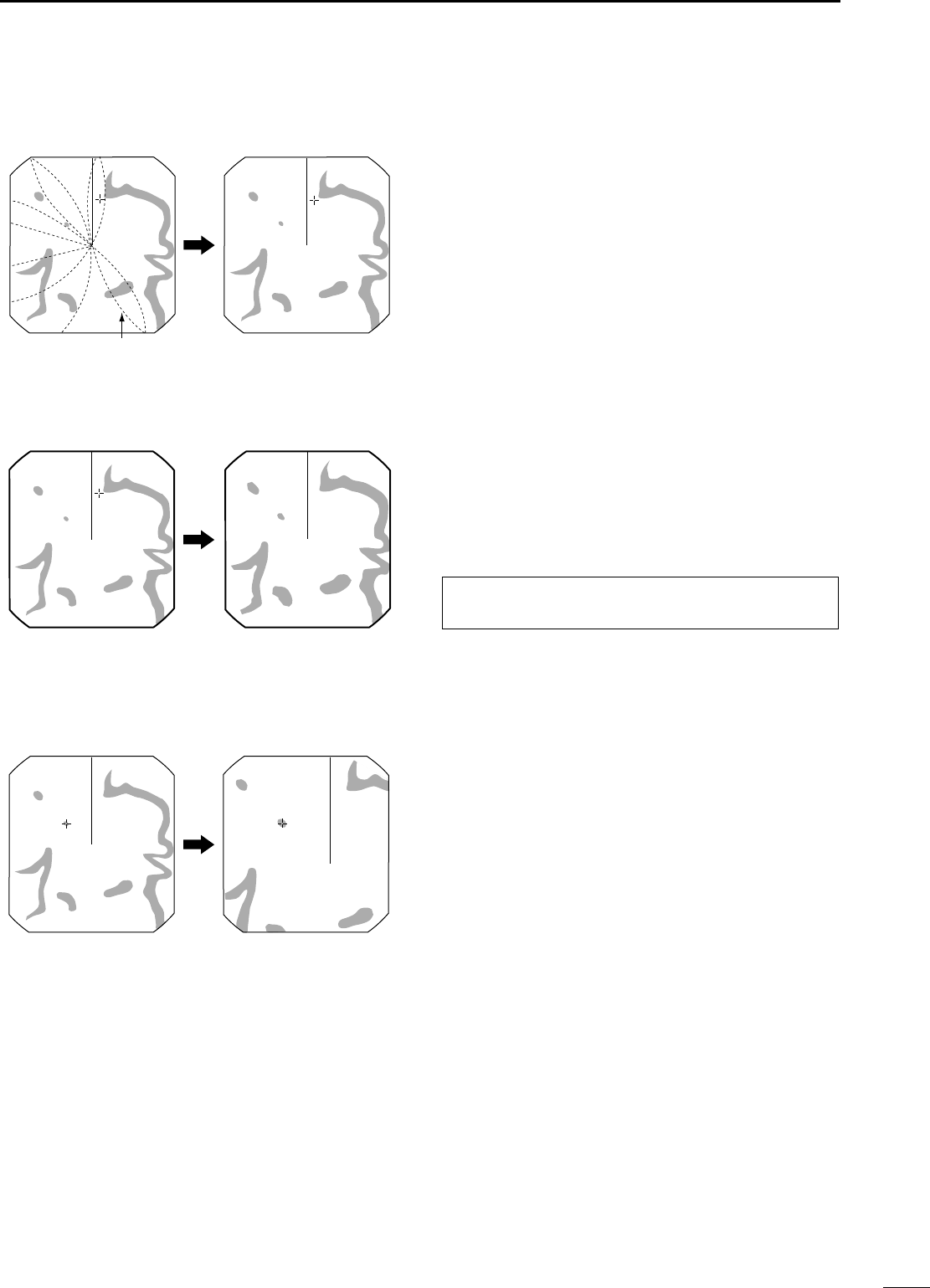
5DISTANCE AND DIRECTION MEASUREMENTS
14
■Distance measurement
Two measurement procedures are available with this
radar. Operating them separately or jointly is possible.
The distance unit, nautical miles (NM) or kilometers
(KM) is selected in the FUNCTION menu (p. 6).
DUsing the fixed rings
qPush [MENU] several times to call up the FUNC-
TION menu.
wPush [Ú] until the “RING” section becomes high-
lighted.
ePush [≈]to select RING function ON and display
the fixed ring.
•The interval range appears on the right of the screen
range readout.
•The ring range is fixed depending on the screen range.
(See below.)
rPush [MENU] several times to exit the menu.
tTo clear the fixed rings, push [Ω]to select OFF in
step e above.
DUsing the variable range marker
qPush [EBL1 (VRM1)] to display the VRM1 and
EBL1; then, push [Ù Ú] to set the marker.
• The range between the ship and the target is indicated
in the VRM readouts.
wPush [EBL2 (VRM2)] to display the VRM2 and
EBL2; then, push [Ù Ú] to set the marker.
• The range between the ship and the target is indicated
in the VRM readouts.
•When the VRM1 and EBL1 are displayed, the center of
VRM2 appears at the intersection point of the VRM1 and
EBL1.
•The VRM2 disappears when [EBL1 (VRM1)] is pushed.
ePush [EBL1 (VRM1)] to exit the menu display.
Range (nm)
Ring (nm)
1 1.5 2 3 4 6 8 12 16 24 32 36 48*
1⁄81⁄41⁄23⁄4
25534646464646466
1122448 86
1⁄20 1⁄20 1⁄10 1⁄41⁄41⁄41⁄21⁄2
NOTE: When the screen is shifted, the number of rings may differ.
*Available for the MR-1000TII only.
1
(0.25)
T.VECT
0.900NM
NM CURS
SOG 0.0KT H UP
014.6˚T
HDG
IR
ES
EBL1
EBL2
W
PT
VRM1
VRM2
CURS 34 ˚ 37.72N 13 5˚ 34.42E
Fixed ring
Ring range readout
TYPE
RING
VRM1
VRM2
DESCRIPTION
Displays fixed rings.
Suitable for rough estimations from your
own ship to any target.
Displays a variable range marker and ac-
tivated by the [Ù Ú] for the range marker
selector.
Suitable for accurate measurements from
your own ship to a target.
Normally functions the same as VRM1.
When the VRM1 and EBL1 selects a tar-
get, the center of VRM2 appears at the
intersection point.
Suitable for accurate measurements from
target to target.
MR-1000R2_T2_FCC.qxd 05.5.17 9:18 Page 14
15
5
DISTANCE AND DIRECTION MEASUREMENTS
■Bearing and Distance measurement
This radar has 2 Electronic Bearing Lines (EBL) to in-
dicate the target direction from your ship or a target.
DUsing the EBL and VRM
qPush [Ù Ú Ω≈]to move the cursor on the desired
target.
wPush [EBL1 (VRM1)] to display the EBL1 and
VRM1.
•Push [Ω ≈] to rotate the electronic bearing line.
•Push [≈] to rotate clockwise and push [Ω] to rotate
counterclockwise.
•Push [Ù Ú] to increase or decrease the variable range
marker ring size.
•The EBL1 and VRM1 readouts indicate the target bear-
ing and distance.
•The EBL readouts indicate the target bearing;
0 to 360°R : Relative direction, when ‘360°R’is se-
lected in the EBL/PI of the FUNCTION
menu. (see p. 6)
P/S 0 to 180°: Bow direction, when ‘PT/SB’is selected
in the EBL/PI of the FUNCTION menu.
(see p. 6)
0 to 360°T* : True or magnetic bearing, when select-
ing ‘TRUE’in the EBL/PI of the FUNC-
TION menu. (see p. 6)
*Bearing data is required. (p. 39)
ePush [EBL1 (VRM1)] to clear the EBL1 and VRM1.
•Cursor remains on the display.
rPush [Ù Ú Ω ≈] to move the cursor on the desired
target.
tPush [EBL2 (VRM2)] to display the EBL2 and
VRM2 on the display.
•When the EBL1 and VRM1 are displayed, the beginning
of EBL2 and VRM2 appears at the intersection point of
the EBL1 and VRM1.
•The EBL2 and VRM2 disappears when [EBL1 (VRM1)]
is pushed.
yTo clear the EBL1 and VRM1, push [EBL1 (VRM1)].
3/4
TVECT 3M
1141NMNM CURS
SOG 00
km/h
H UP
3240
R
HDG
IR
EBL1 3151
˚T
EBL2 2471
˚T
WPT 34
VRM1 0503NM
VRM2 0359NM
POSN
EBL1
VRM1
EBL2
EBL1
readout
EBL2
readout
VRM2
VRM1 readout
VRM2 readout
MR-1000R2_T2_FCC.qxd 05.5.17 9:18 Page 15
■Advanced measurements
Using both Electronic Bearing Lines (EBL) and both
Variable Range Markers (VRM), the following ad-
vanced measurements can be made:
DMeasuring the distance and direction between 2 targets
qPush [Ù Ú Ω ≈] to move the cursor on the desired
target.
wPush [EBL1 (VRM1)] to display the EBL1 and
VRM1.
•Push [Ω ≈] to rotate the electronic bearing line.
•Push [Ù Ú] to increase or decrease the variable range
marker ring size.
ePush [EBL2 (VRM2)] to display the EBL2 and
VRM2.
•The intersection of the EBL1 and VRM1 becomes the
center of the EBL2 and VRM2.
rPush [Ù Ú Ω ≈] to move the cursor on the other
target.
•Push [Ω ≈] to rotate the electronic bearing line.
•Push [Ù Ú] to increase or decrease the variable range
marker ring size.
tThe VRM2 readout shows the distance between the
two targets. The EBL2 readout shows the direction
from one target to the other.
DMeasuring the relative speed and course of a target
qPush [TRAILS] (p. 12) ON; then wait until the trail
time count up reaches to the TRAIL TIME.
wSet VRM1 and EBL1 to a previously plotted target
as described above.
eSet VRM2 and EBL2 to the current plotted position
of the same target as described as above.
rThe VRM2 readout is a measure of target move-
ment which can be converted into relative target
speed.
•For example, when a 6 min. trail time is selected, multi-
plying the distance by ten gives the relative average
speed of the target.
•If your ship is stationary during the plotting time, the
converted speed and direction become absolute.
•The converted speed unit is knots or kilometers/hour
when the selected unit in the FUNCTION menu is nauti-
cal miles (NM) or kilometers (KM), respectively.
tThe EBL2 readout shows the course direction of the
target.
• Measuring the distance and course from a waypoint
qDisplay a waypoint. (see p. 13)
wSet VRM1 and EBL1 to the displayed waypoint tar-
gets as described above.
eSet VRM2 and EBL2 to a target (e.g. the next way-
point) as described above.
rThe VRM2 readout shows the distance to the target
from the waypoint.
•The distance unit can be selected as nautical miles (NM)
or kilometers (KM) in the FUNCTION menu.
tThe EBL2 readout shows the direction to the target
from the waypoint.
3/4
TVECT 6M
1141NMNM CURS\
SOG KT H UP
3171
˚M
HDG
IR
ES
EBL1 3211
˚T
EBL2 1714
˚T
WPT
VRM1 0401NM
VRM2 0184NM
POSN
VRM2
EBL2
EBL1
VRM1
3/4
MTUNE TVECT 3M
1141NMNM CURS\
SOG
km/h
H UP
3171
˚M
HDG
IR
ES
EBL1 3211
˚M
EBL2 0890
˚T
WPT
VRM1 0852NM
VRM20814NM
POSN
ALM
GYRO
GPS
EBL2
EBL1
VRM2
VRM1
5DISTANCE AND DIRECTION MEASUREMENTS
16
MR-1000R2_T2_FCC.qxd 05.5.17 9:18 Page 16
The unit has an alarm function to protect your ship from collisions. If other ships or islands, etc. come into the pre-
programmed alarm zone, the function alerts you with an alarm. You can set the desired range and bearing for an
alarm zone. While the alarm function is activated, the power save function turns the CRT OFF until an alarm is
given, to conserve power.
■Alarm zone setting
DSetting and using the alarm function
qPush [+] or [–] to select the desired range.
wPush [Ω ≈ Ù Ú] to set the cursor to the starting
point of the alarm zone.
ePush and hold [ALM] for 1 sec. to enter the alarm
zone setting.
•The starting zone appears on the screen. (Fig. 1)
rPush [Ω≈]to adjust an angle and push [Ù Ú]to
set the distance of the alarm zone.
•The selected alarm zone appears.
tPush [ALM] to fix the alarm zone and activate the
alarm function.
•“ALM” appears on the bottom of the screen.
•The selected alarm zone remains.
yIf a target comes into or goes out of the alarm zone,
an alarm beep is emitted.
•Push [ALM] to cancel the alarm signal and function .
uTo deactivate the alarm function, push [ALM].
•“ALM” and alarm zone disappear from the screen.
iTo activate the alarm function again with the same
programmed zone, push [ALM].
•
“ALM” and pre-programmed alarm zone appears. (Fig. 2)
• Using the function with power saver
To activate the power save function, push and hold [TX
(SAVE)] for 1 sec. while the alarm function is turned
ON.
•The CRT display turns OFF.
•When a target comes into the alarm zone, an alarm sig-
nal is emitted, the CRT display turns ON and the power
save function is cancelled.
■Zone alarm setting
Zone alarm beep is emitted when the target comes
into the zone, or the target goes out of the zone. (p. 6)
qPush [MENU] several times to call up the FUNC-
TION menu.
wPush [Ú] until the “ZONE ALARM” section becomes
highlighted.
ePush [Ω ≈] to select IN or OUT
•IN : Alarm sounds when the target comes into the
zone. (see Fig. 3)
•OUT: Alarm sounds when the target goes out of the
zone.
Alarm sounds when the target
comes into the zone.
Alarm zone
Fig. 3
Target (other ship, etc.)
3/4
(0.25)
TVECT 3M
0189NM
NM CURS\
SOG177KT H UP
0525
˚T
HDG2739
˚T
IR
ES
EBL1
EBL2
WPT
VRM1
VRM2
CURS 34
˚
3772N 135
˚
3442E
GYRO
GPS
ALM
3/4
(0.25)
TVECT 3M
0397NM
NM CURS\
SOG177KT H UP
3143
˚T
HDG2739
˚T
IR
ES
EBL1
EBL2
WPT
VRM1
VRM2
CURS 34
˚
3772N 135
˚
3442E
GYRO
GPS
Push
[Ω ≈ Ù Ú]
“ALM”
appears
Fig. 1
Fig. 2
ALARM FUNCTION 6
17
MR-1000R2_T2_FCC.qxd 05.5.17 9:18 Page 17
■ATA (Automatic Tracking Aid)
By tracking automatically the target chosen by the cursor key, the closest point of approach (CPA) and the time to
closest point of approach (TCPA) limit of a own ship and a target are calculated.
ATA is the function to tell about to alarm sound, when both CPA and TCPA becomes below a setting value (the ap-
proach watch area).
The range of the target which can be registered is taken as a target with a highest luminosity level of 0.2–16 miles.
•Max. 10 targets can be plotted on the screen.
•Plot positions shall be identified by an approved symbol mark (p. 20) and associated plot number.
•The vector origin will move across the screen at a rate and direction defined by the calculated true or relative
course and speed.
•The vector will be displayed on the target.
•Display accuracy may increase by the self-ship and course change of target or acceleration, slowdown, etc.
■ATA menu setting
Set the ATA menu items before using the ATA function.
qPush [MENU] several times to turn the ATA menu
ON.
wPush [≈] to turn the ATA function ON.
ePush [Ú] to select the “No. DISP” to select the tar-
get identification number type which appears at the
right side of the mark. Push [Ω ≈] to select the ap-
propriate type.
•OFF: No number appears.
•SEL: Number appears by the selected mark only.
•ALL: All numbers appear by the marks.
rPush [Ú] to select “VECT”; push [Ω ≈] to select the
vector type.
•TRUE (True vector):
The predicted true motion of a target as the result of your
own ship’s direction and speed input.
•REL (Relative vector):
The predicted movement of a target relative to your own
ship.
tPush [Ú] to select “OWN VECT”; push [Ω ≈] to turn
the own vect function ON or OFF.
•OFF: For not displaying the own ship vector.
•ON: To display your own ship’s vector.
yPush [Ú] to select “ALARM”; push [Ω ≈] to turn the
alarm function ON or OFF.
•ATA alarm is emitted when both CPA and TCPA reaches
the limit.
uPush [Ú] to select the “CPA* LIMIT”; push [Ω ≈] to
set the CPA limit distance.
iPush [Ú] to select the “TCPA* LIMIT”. Push [Ω ≈]
to set the TCPA limit time.
*CPA/TCPA: Closest Point of Approach and Time to
Closest Point of Approach limit is defined by the ob-
server to a given warning when a target or targets are
close to within those limits from your own ship.
oPush [MENU] to exit the ATA menu.
ATA MENU
VECT
No.DISP OFF ALL
OWN VECT
ALARM
CPA LIMIT
TCPA LIMIT
TRUE
ON
ON
ON
OFF
REL
OFF
OFF
1.0NM
1 MIN
ATA
SEL
ATA (Automatic Tracking Aid)
7
18
MR-1000R2_T2_FCC.qxd 05.5.17 9:18 Page 18
■ATA operation
Select the target which you want to track on the dis-
play.
qPush [Ù Ú Ω ≈] to move the “+” cursor on the de-
sired target.
wPush [TARGET] for 1 sec. to select the target for
tracking.
•Dotted square symbol appears on the cursor.
•Target identification number, bearing, distance readout,
course (CSE), speed (SPD), CPA and TCPA appear in
the information screen.
• Timer starts to count the progressing time.
• The vector appears on the target, after the progressing
time of 20 sec. has passed.
• It changes to the circle display of a solid line and a vec-
tor display, and tracking operation is decided, after the
progressing time of one min. has passed.
• When the target which is following disappears, a mark
changes to a lozenge and is blinked. A mark disappears
after one min..
• When a target advances within a setting value, a mark
changes to a triangle, blinks and sounds alarm sound.
Alarm sound will be cancelled if one of key is pushed.
• To cancel the target setting, move the cursor on the tar-
get, then push [TARGET] for 1 sec.
• [TARGET] is pushed for changing the display of
EBL/VRM etc. to target information.
• In order to choose target which displays information,
cursor is united with target and [TARGET] is pushed.
■Plotting marks There are 5 kinds of plotting marks.
: Selected, uncalculated mark.
: Selected, calculated mark.
: Normal, calculated mark.
: CPA/TCPA alarm mark. The target is
close to within a minimum range and
time. Alarm emit indicator. Push [TAR-
GET] to cancel the alarm.
: When the tracking of a target disap-
pears.
■Course and speed vector
The vector indicates the target’s predicted, true or rel-
ative course and speed.
•Vector time may change depending on the TRAIL TIME set-
ting. (see VIDEO menu, p. 6)
•The tip of the vector shows the target’s predicted position
after a certain time, which has been selected in the “TRAIL
TIME”.
Vector
Current position
Vector time
Target’s predicted
positon
NEW BRG
CSE
CPA
DIST
SPD
TCPA
No.10 BRG 305.7T
0:20
CSE 081.3T
CPA 5.9NM
DIST 11.43NM
SPD 12.3KT
TCPA 0:50
Identification No.
Bearing Course Distance Speed
Passage of time
Closest Point of
Approach
Time to Closest Point of
Approach
ATA (Automatic Tracking Aid)
19
7
MR-1000R2_T2_FCC.qxd 05.5.17 9:18 Page 19

■Plots
Plot displays past position of targets every 1 min. as 3
dots.
qTarget goes straight.
wTarget turns right.
eTarget reduces speed.
rTarget increases speed.
qwer
7ATA
20
MR-1000R2_T2_FCC.qxd 05.5.17 9:18 Page 20
■Indirect echoes
Indirect echoes may be returned from either a passing
ship, or returned from a reflecting surface, such as a
mast on your own ship.
An indirect echo from a reflecting surface will appear
on a different bearing from the direct (true) echo, but
the distance will be approximately the same for both.
Indirect echo
True echo
True echo
False echo
An echo is reflected at this point.
Own ship
Target
Bridge
Target
Scanner
Mast or
similar obstruction
■Side-lobe echoes
Radiation can escape on each side of the beam inside
the lobes. If a target reflects this radiation, it will be dis-
played on the screen as an echo.
Side-lobe echoes usually occur at short ranges and as
a result of large (strongly reflective) targets. They can
be reduced with proper adjustment of the [SEA] con-
trol.
See p. 10 for the [SEA] control.
False
echoes
True
echo
Main beam
Side lobes
Radar uses a form of electromagnetic radiation, which like light, can be reflected. Because of this property, some
objects may cause false echoes on the screen where in fact no targets actually exist.
These echoes may appear if a large vessel, bridge, or tank is in proximity. Operators should be familiar with the ef-
fects of these phenomena. In some cases, echoes can be reduced.
8
BASIC RADAR THEORY
21
MR-1000R2_T2_FCC.qxd 05.5.17 9:18 Page 21
8BASIC RADAR THEORY
22
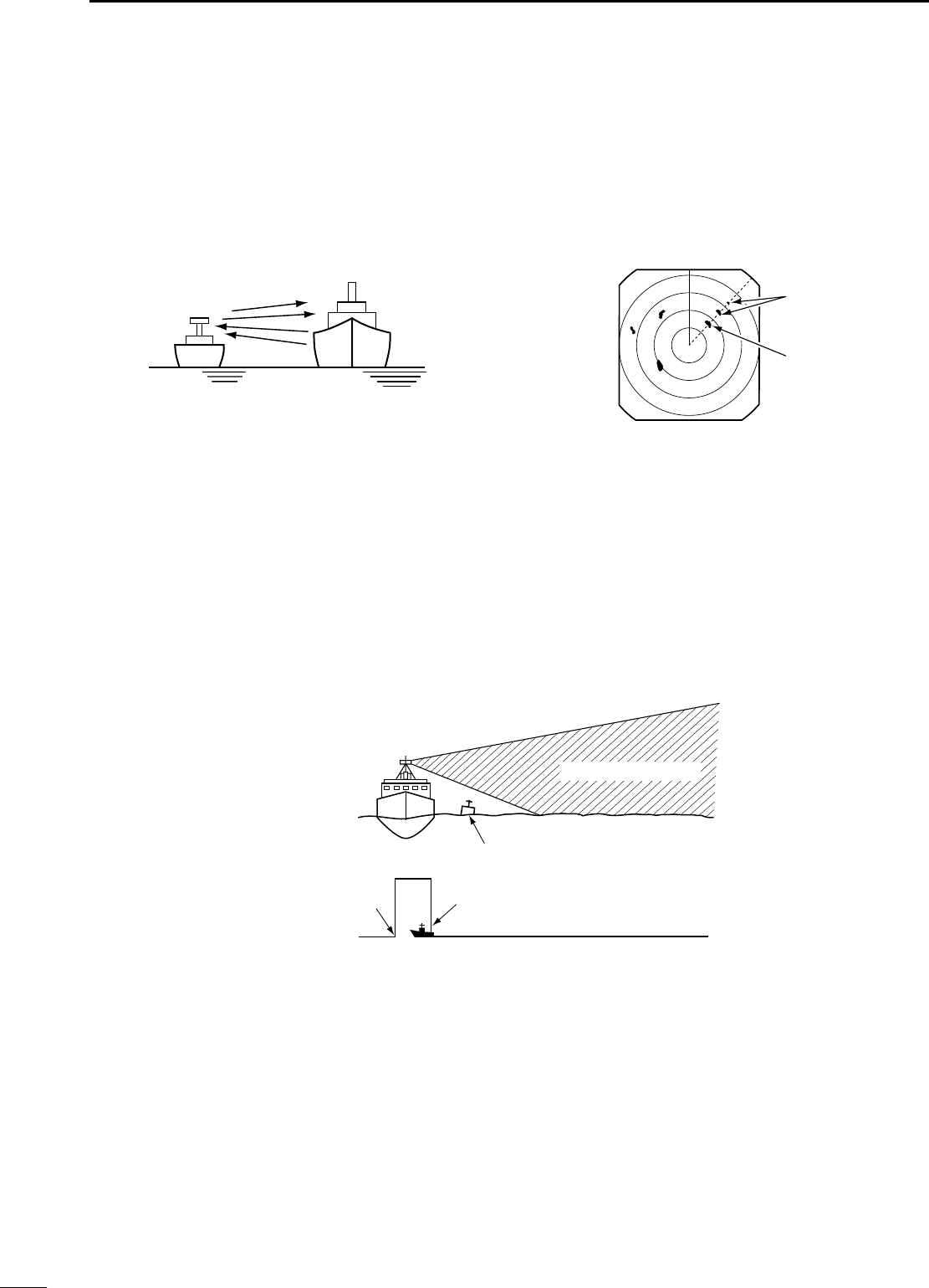
■Multiple echoes
Multiple echoes may appear when a short-range and
strong echo is received from a ship, bridge, or break-
water.
Multiple echoes will appear beyond the target’s true
echo point on the same bearing of a large target. They
can be reduced with proper adjustment of the [SEA]
control.
See p. 10 for the [SEA] control.
True echo
False echoes
Own ship Another ship
■Minimum range
Detection at short range is very important. Minimum
range is determined primarily by transmitter pulse
length, vertical beam width and height of the scanner
unit. The shorter the transmission time, the quicker the
return echoes can be received and their distance mea-
sured.
The ability to see targets very close to the ship is de-
creased if the scanner is mounted too high off the
water, because the bottom of the vertical beam of the
scanner cuts off nearby targets.
This target can not be recognized with radar.
The target in this area can not be recognized.
Pulse length
Pulse starting point
Vertical beam width
MR-1000R2_T2_FCC.qxd 05.5.17 9:18 Page 22
8
BASIC RADAR THEORY
23
■Blind and Shadow sectors
Blind or Shadow sectors may exist because of ob-
structions such as masts, derricks or stacks. An ob-
struction may throw either a complete or partial
shadow as shown in the diagram below. If a target is in
a shadow sector, target echoes may not appear on the
screen.
When tall and massive targets such as a large island
are located at close range also shadowed without pro-
ducing any echoes. This phenomenon is called blind
sector. It is very important to know the bearings and
widths of all shadow sectors caused by your own
ship’s obstructions.
Blind sector
Own ship Large
island
Small
island
Mast or
similar
obstruction
Shadow sector
■Target resolution
Target resolution is determined by the horizontal beam
width and transmit pulse width. Sometimes it is difficult
to detect two targets which are separated by short dis-
tances or which are in the same direction.
DDistance resolution
When two targets are separated by more than the
pulse width, they appear as two echoes.
When two targets are not separated by more than
the pulse width, they appear as 1 echo.
DDirection resolution
When two targets are separated by more than the
horizontal beam width, they appear as two echoes.
When two targets are not separated by more than
the horizontal beam width, they appear as one echo.
Scanner
Target 2
Target 1
Target 1, 2
Target 2
Target 1
Scanner
Target 2
Target 1
Transmit
pulse
Echo
Target 1,2
Target 1, 2
Transmit
pulse
Echoes
Target 1 Target 2
Target 2
Target 1
MR-1000R2_T2_FCC.qxd 05.5.17 9:18 Page 23
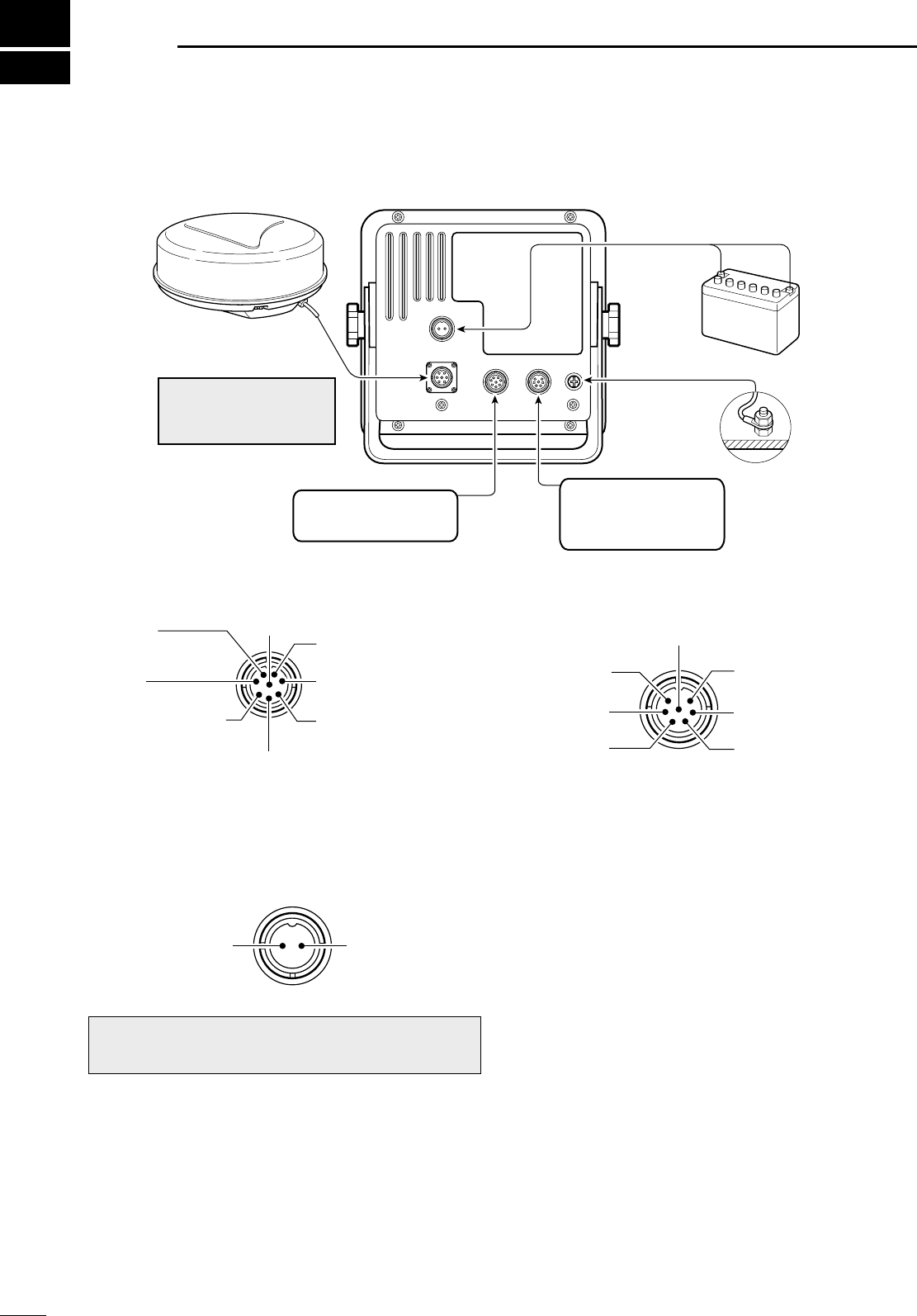
■Connecting the units
NMEA1 connection NMEA2 connection
■Power source requirement
DDC power source
The radar is designed for connection to any power
source if the voltage is 10.2–42 V DC, so that a 12, 24,
or 32 V DC battery can be used without a DC-DC con-
verter, or any internal modifications.
• DC power cable connection
Connect the supplied DC power cable as shown in the
diagram.
■Ground connection
To prevent electrical shocks and other problems, ground the display unit through the [GND] terminal on the unit’s
rear panel. For best results, connect a heavy gauge wire or strap to the nearest grounding point on the boat. The
distance between the [GND] terminal and the ground point should be as short as possible.
CAUTION:Incorrect cable connection may dam-
age the radar.
DC input Ground
q N TXT
(NMEA 2 output)
w RXD
i GND u N.C
y AUX input (–); CLOCK
or N+1(–) data input
t AUX input (+); CLOCK
or N+1(+); data input
r NMEA 1 input (–)
or AUX input (–); DATA
e NMEA 1 input (+)
or AUX input(+); DATA
NMEA1:
Bearing data input
NMEA2:
NMEA 0183 data input
Speed sensor input
+
Ground
Power supply
10.2 to 42 V DC
Red: Black: _
PWR
GND
NEVER connect any-
thing other than the sup-
plied scanner unit.
Supplied scanner unit
9INSTALLATION AND CONNECTIONS
24
q NMEA 2
output (+)
w NMEA 2
output (–)
e NMEA 2
input (+)
u GND (Speed sensor)
y Speed sensor
input
t Regulated 12 V output.
(20 mA Max.)
r NMEA 2 input (–)
MR-1000R2_T2_FCC.qxd 05.5.17 9:18 Page 24
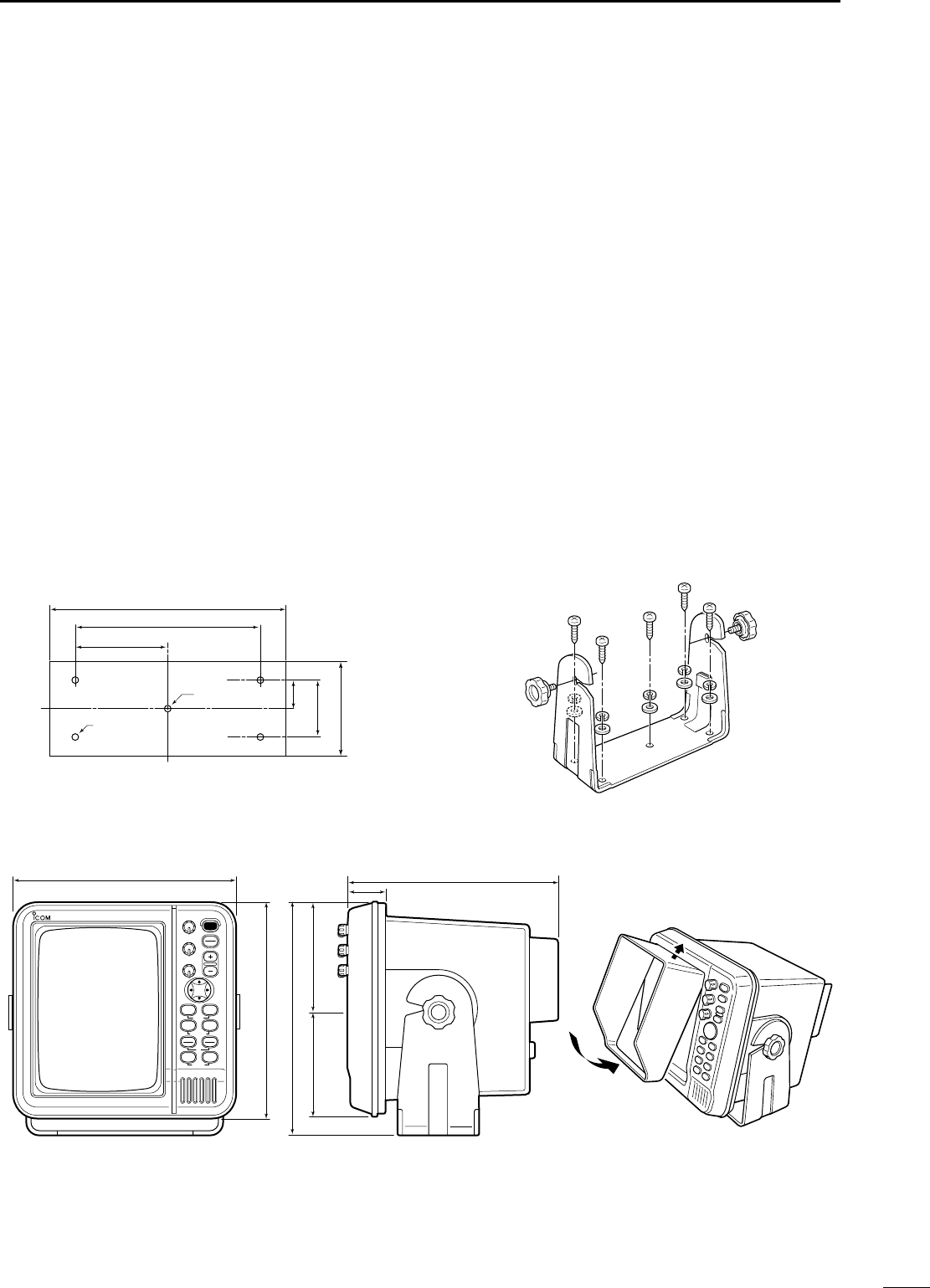
•SX-2713/2779
MOB
POWER
TX
SAVE
TARGET
TRAILS
ZOOM
ALM
MODE
OFF CENT
EBL1
VRM1
PI
BRILL MENU
HL OFF
EBL2
VRM2
MARINE RADAR
269 (1019⁄32) 258 (105⁄32)
48 (129⁄32)
264 (1013⁄32)
287 (117⁄16)
132 (53⁄16)132 (53⁄16)
• Viewing hood installation
•SX-2713/2779 Mounting Bracket •Mounting Bracket installation
Fig. 2
250 (927⁄32)
195 (711⁄16)
97.5 (327⁄32)
100 (315⁄16)
60 (23⁄8)
30 (13⁄16)
Ø7 (9⁄32)×4
Ø7 (9⁄32)
Fig. 1
9
INSTALLATION AND CONNECTIONS
25
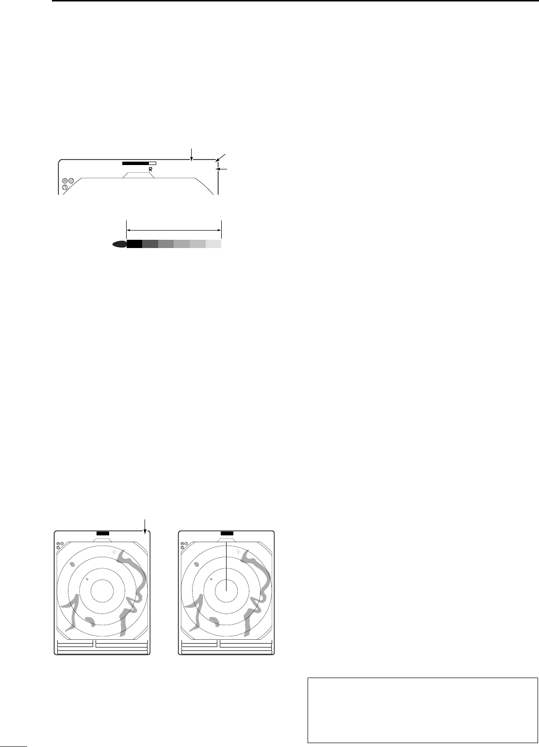
■Installing the display unit
DLocation
Select a place for installation which meets the following
important conditions:
qThe display unit should be placed near the wheel in
the cabin so that an operator may easily view the
radar screen while facing the bow.
wTo minimize interference, KEEP the unit AT LEAST
THE COMPASS SAFE DISTANCE stated in the se-
rial No. seal on the rear panel away from the com-
pass and navigation receiver.
eSelect a position where there is no danger of salt or
fresh water spray or immersion.
rSelect a location where it is easy to perform main-
tenance or adjustment after installation.
tSelect a location which can support the weight of
the display unit.
yDO NOT select areas subject to extreme heat, cold,
vibrations or direct sunlight.
DMounting
The mounting bracket supplied with the display unit al-
lows “dashboard” or “overhead” mounting.
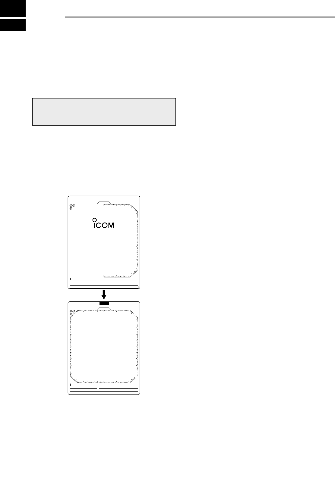
qHold the mounting bracket up to the selected loca-
tion and mark pilot holes for the 5 installation holes
using the template.
•The template is provide on p.41.
wDrill 5 holes of 3 mm (1⁄8in) in diameter as shown
in the diagram. (Fig. 1)
eInstall the bracket using the screws, nuts, bolts or
washers, with the supplied accessories. (Fig. 2)
rAdjust the display unit to an adequate view angle.
tInstall the supplied viewing hood.
MR-1000R2_T2_FCC.qxd 05.5.17 9:18 Page 25
9
26
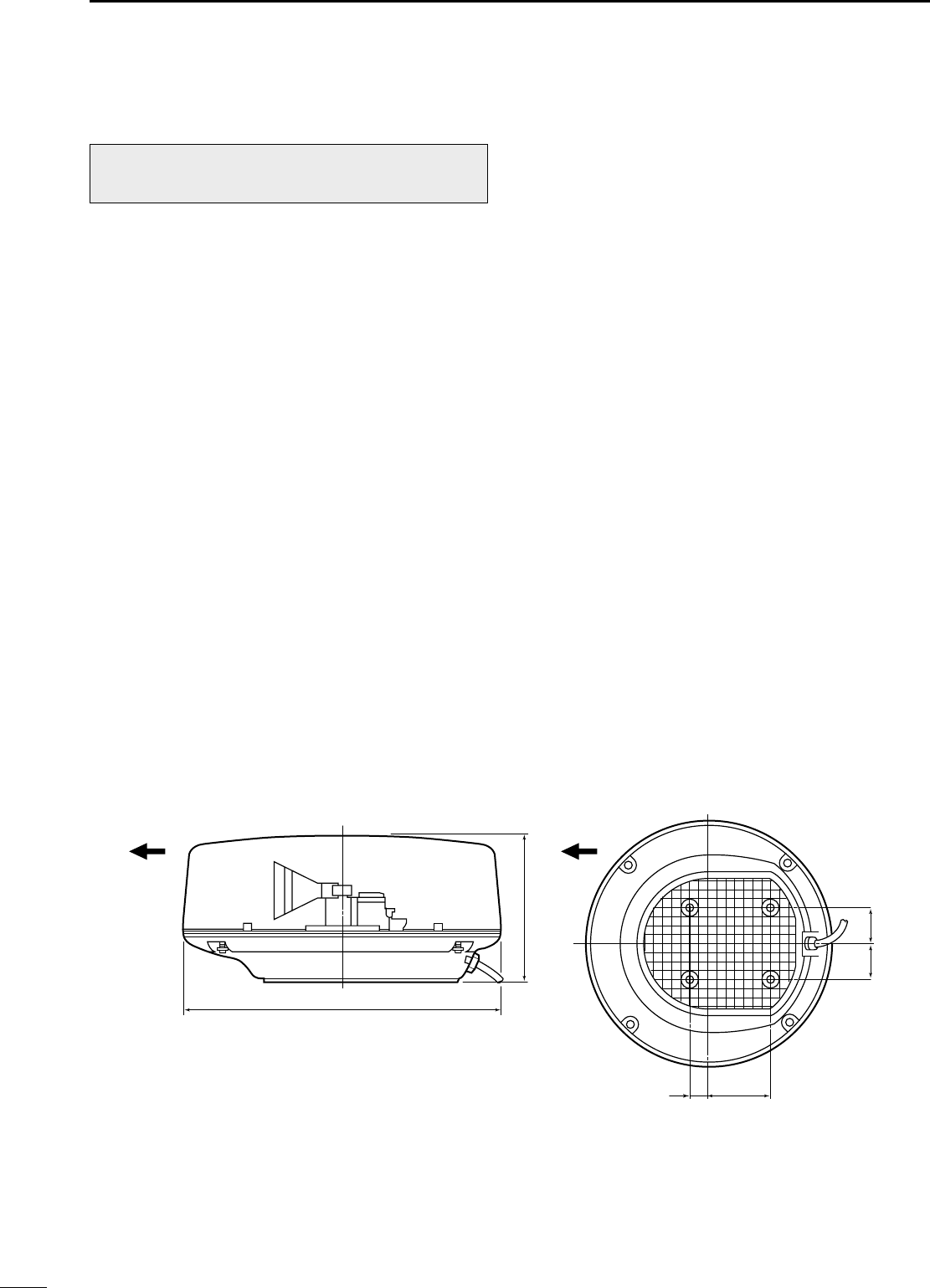
■Mounting the EX-2714 scanner unit
DLocation
The scanner unit is designed to be weatherproof and
completely watertight. Select a place for installation
which meets the following important conditions.
qThe scanner unit must be near the boat’s center line
and have a good view in every direction. Be sure
there are no objects in the surrounding area which
will intercept the scanning beam.
wKEEP the scanner unit away from any smoke-
stacks. Smoke can damage the unit.
eWhen the boat is equipped with a radio directional
finder (RDF) system, keep the scanner unit at least
2 m (6.6 ft) away from any RDF antenna.
• Radiation from the scanner unit can affect the measure-
ment data of RDF equipment.
rThe unit should be placed as high as possible (at
least 5.5 m; 18 ft vertically above the main deck and all
possible personnel) on the boat to obtain best perfor-
mance with maximum range. (See p. 51 for details)
tIf you install two or more radar in one boat, install
one above, and one below.
yThe mounting surface must be parallel with the
boat’s waterline.
uIf the height is insufficient to install the scanner unit,
build a special frame for installation.
DMounting
qDrill four holes of 12 mm (1⁄2in) in diameter using
the template.
wIf the mounting surface or platform is metal, apply
sealing compound around the holes to prevent cor-
rosion and to waterproof the unit.
eFix the scanner unit to the selected position with
bolts of 10 mm (3⁄8in) in diameter, with flat and
spring washers. The supplied bolts are two lengths:
25 mm (1 in) or 50 mm (2 in).
CAUTION: SECURE the four bolts tightly.
WARNING: BE SURE [POWER] is OFF when-
ever you are working with the scanner unit.
607 (2329⁄32)
45.5 (113⁄16) 150.5 (515⁄16)
243 (99⁄16)
90.5 (39⁄16)90.5 (39⁄16)
Ship’s bow direction Ship’s bow direction
Unit: mm (in)
INSTALLATION AND CONNECTIONS
MR-1000R2_T2_FCC.qxd 05.9.5 16:38 Page 26
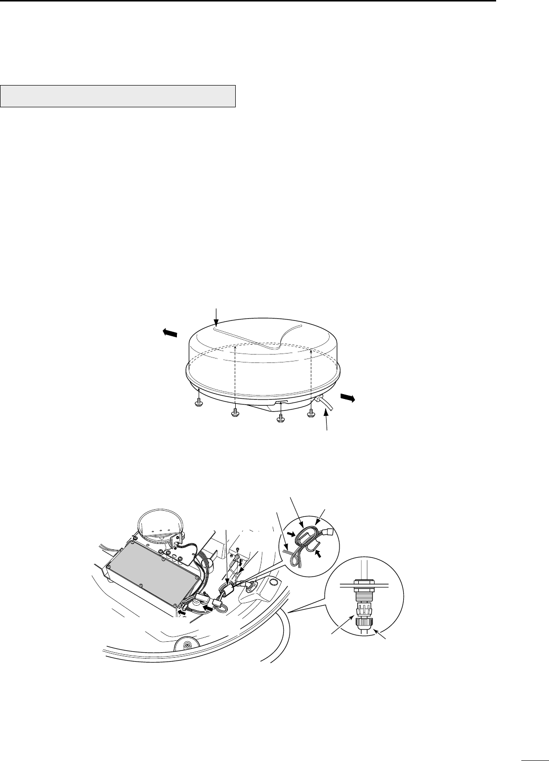
27
9
INSTALLATION AND CONNECTIONS
■Wiring the EX-2714 system cable
qLoosen the four bolts using a hex head wrench on
the bottom of the scanner unit, and open the unit.
wLoosen the nut on the scanner unit and pass the
system cable through the nut and sealing tube.
eInsert the PA cable (black and white) connector to
the PA unit connector J1. (*1; Be sure to follow the
following diagram carefully)
rConnect the shielding wire to the ground plate with
the screw as shown in the diagram.
tClamp the system cable with the ferrite bead at-
tached near the sealing connector. Be sure to clamp
it tightly.
•Scanner unit disassembly
yConnect the power cable (black and red) end to the
power unit connector. (*2; Be sure to follow the fol-
lowing diagram carefully).
uTighten the sealing-nut, then replace the radome
cover over the scanner unit.
DO NOT stretch the system cable too much, other-
wise miss contact of the connector may occur.
iTighten the four bolts on the bottom of the scanner
unit.
•The four projections around the circumference of
the radome cover show the positions of the bolt
receptacles.
CAUTION: NEVER cut the supplied system cable.
Ship’s bow direction
Face the Ω mark in the direction
of the ship’s bow.
Stern
System cable
Scanner unit disassembly
•Connect the system cable
Ferrite bead
Shielding
wire
PA cable
Power cable Round the PA
cable twice.
Sealing tube Nut
*2; Power
connector
*1; PA cable
MR-1000R2_T2_FCC.qxd 05.5.17 9:18 Page 27
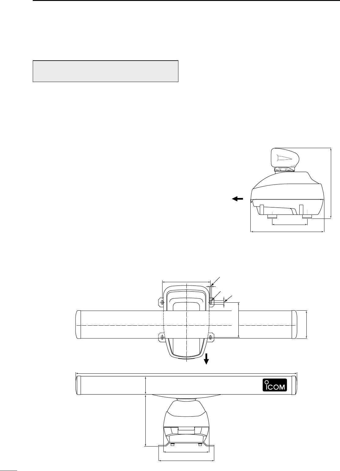
■Mounting the EX-2780 scanner unit
• Location
The scanner unit is designed to be weatherproof and
completely watertight. Select a place for installation
which meets the following important conditions.
qThe scanner unit must be near the boat’s center line
and have a good view in every direction. Be sure
there are no objects in the surrounding area which
will intercept the scanning beam.
wKEEP the scanner unit away from any smoke-
stacks. Smoke can damage the unit.
eWhen the boat is equipped with a radio directional
finder (RDF) system, keep the scanner unit at least
2 m (6.6 ft) away from any RDF antenna.
• Radiation from the scanner unit can affect the measure-
ment data of RDF equipment.
rThe unit should be placed as high as possible (at
least 5.5 m; 18 ft vertically above the main deck and all
possible personnel) on the boat to obtain best perfor-
mance with maximum range. (See p. 51 for details)
tIf you install two or more radar in one boat, install
one above, and one below.
yThe mounting surface must be parallel with the
boat’s waterline.
uIf the height is insufficient to install the scanner unit,
build a special frame for installation.
• Mounting
qDrill four (4) holes of 12 mm (1⁄2in) in diameter
using the template.
wIf the mounting surface or platform is metal, apply
sealing compound around the holes to prevent cor-
rosion and to waterproof the unit.
eFix the scanner unit to the selected position with
bolts of 10 mm (3⁄8in) in diameter, with flat and
spring washers. The supplied bolts are two lengths:
25 mm (1 in) or 50 mm (2 in).
CAUTION: SECURE the four bolts tightly.
Ship’s bow direction
190 (715⁄32)
399 (1723⁄32)
381 (15)
28
9INSTALLATION AND CONNECTIONS
Ship’s bow direction
302 (1129⁄32)
248 (93⁄4)
1200 (471⁄4)
20.5 (13⁄16)
R5.5 (7⁄32)
11 (7⁄16)
262 (105⁄16)
281 (111⁄16) 98 (37⁄8)
152 (531⁄32)
190 (715⁄32)
WARNING: BE SURE [POWER] is OFF when-
ever you are working with the scanner unit.
MR-1000R2_T2_FCC.qxd 05.9.5 16:38 Page 28
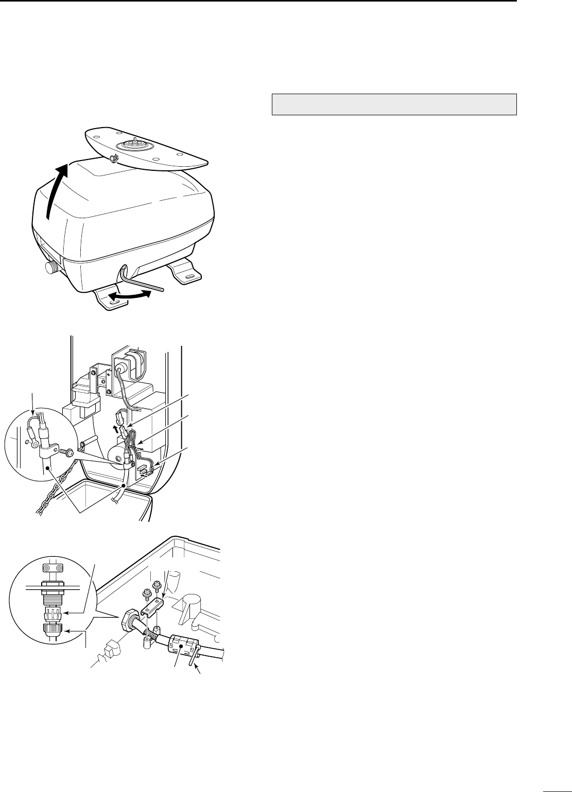
29
9
INSTALLATION AND CONNECTIONS
■Wiring the EX-2780 system cable
qLoosen the four bolts using the supplied hex head
wrench on the bottom of the scanner unit, and open
the unit. (Fig. 1)
wLoosen the nut on the scanner unit and pass the
system cable through the nut and sealing tube.
(Fig. 3)
eConnect the power cable (black and red) end to the
power unit connector through the rouped cable tie.
(Fig. 2)
rInsert the PA cable (black and white) connector to
the PA unit connector. Be sure to follow the diagram
below carefully. (Fig. 2)
tConnect the shielding wire to the chassis with the
screw as shown in the diagram. (Fig. 2)
•Fix the PA cable with the rouped cable tie as illustrated
in Fig. 2.
yClamp the system cable with the cable clamp metal
fitting using a screw near the sealing connector. Be
sure to clamp it tightly. (Fig. 3)
uClamp the system cable with the ferrite core at-
tached near the sealing connector. Be sure to clamp
it tightly. (Fig. 3)
Tighten the ferrite bead with cable tie.
iTighten the sealing-nut (Fig. 3), then replace the
radome cover over the scanner unit. (Fig. 1)
DO NOT stretch the system cable too much, other-
wise miss contact of the connector may occur.
oTighten the four bolts on the bottom of the scanner
unit. (Fixing torque: 9.8 N•m)
Fig. 1
CAUTION: NEVER cut the supplied system cable.
Cable tie
Power cable
PA cable
Fig. 2
Shielding wire
System cable
Sealing bush
Nut
*Ferrite bead *Cable tieFig. 3
*Cable clamp
MR-1000R2_T2_FCC.qxd 05.5.17 9:18 Page 29
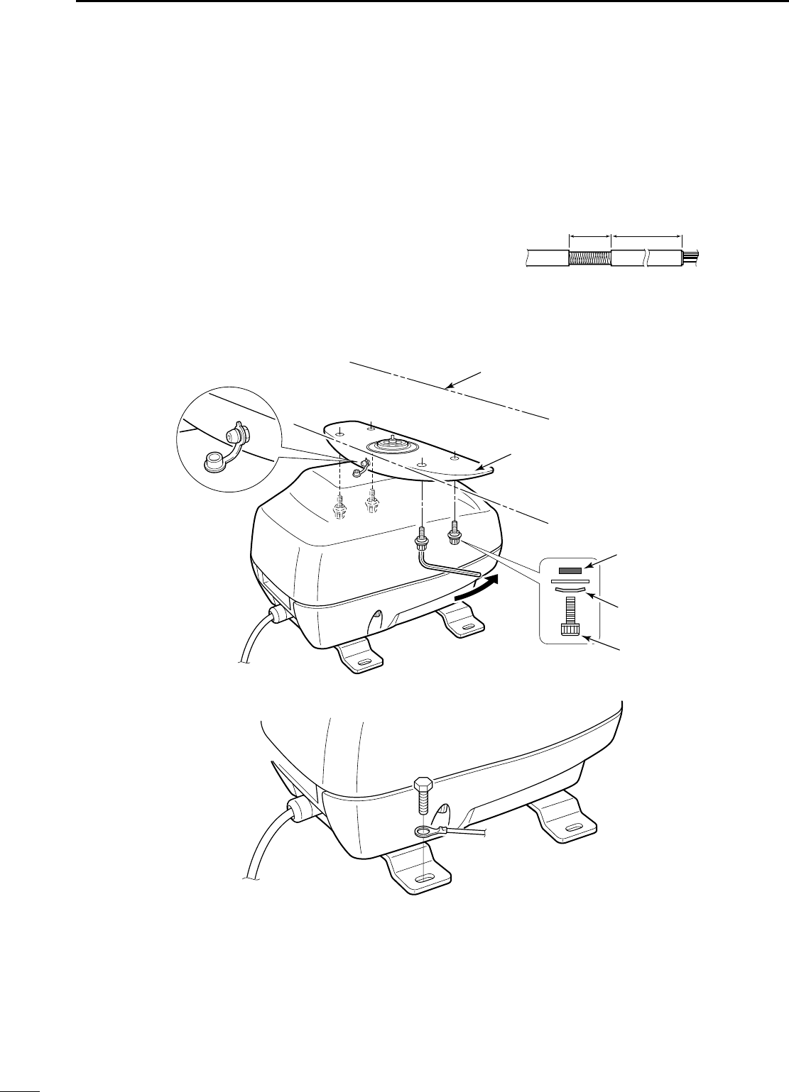
30
9INSTALLATION AND CONNECTIONS
■Fixing the EX-2780 scanner unit
qPut the scanner unit*1on the stay, then fix the an-
tenna rotor with installation bolts of 8 mm (5/16 in)
in diameter, with flat and dish washers and a seal-
ing washer. Be sure to keep the direction of the dish
washer correct as shown in the diagram*2. (Fig. 4)
wApply lubricant specified below or an equivalent one
to the motor bearing*3, if required.
•Manufacture: ESSO
Type: BEACON 325
eConnect the grounding wire to the ground plate with
the supplied terminal if required. (Fig. 5)
NOTE: When using the optional system cable.
Peel the outer sheath of the system cable when using
the optional system cable OPC-1078.
•BE CAREFUL ! DO NOT cut the inner shield wire
when peeling the outer sheath.
(Unit: mm)
➨
➨
Peel the sheath
To the display To the scanner
18±2 410±5
*2
*1Scanner unit
Stay
Sealing
washer
Keep in this
direction
Installation
bolt
*3Lubricant spot
Fig. 4
Fig. 5
MR-1000R2_T2_FCC.qxd 05.5.17 9:18 Page 30

10
31
OTHER FUNCTIONS
DAntenna rotation speed
The antenna rotation speed can be selected from 48
rpm and 36 rpm. (Default: 48 rpm)
Pushing and holding [–] for 1 sec. to select 36 rpm ro-
tation speed, pushing and holding [+] for 1 sec. to se-
lect 48 rpm rotation speed.
DTest pattern indication
To check the CRT indication distortion, a test pattern
can bee displayed.
While pushing and holding [MENU], turn power ON to
display the test pattern.
To return to normal operating condition, turn power
OFF then ON again.
DPara-simulation screen
The MR-1000RII/TII has para-simulation screen capa-
bility.
qWhile pushing and holding [BRILL], turn power ON.
wAfter the count down indication, stand-by screen ap-
pears.
ePush [TX (SAVE)] to display the para-simulation
screen.
rTo return to normal operating condition, turn power
OFF then ON again.
DAll reset
qWhile pushing and holding [TARGET], [EBL1
(VRM1)] and [EBL2 (VRM2)], turn power ON.
wFollow the guidance.
MR-1000R2_T2_FCC.qxd 05.5.17 9:18 Page 31
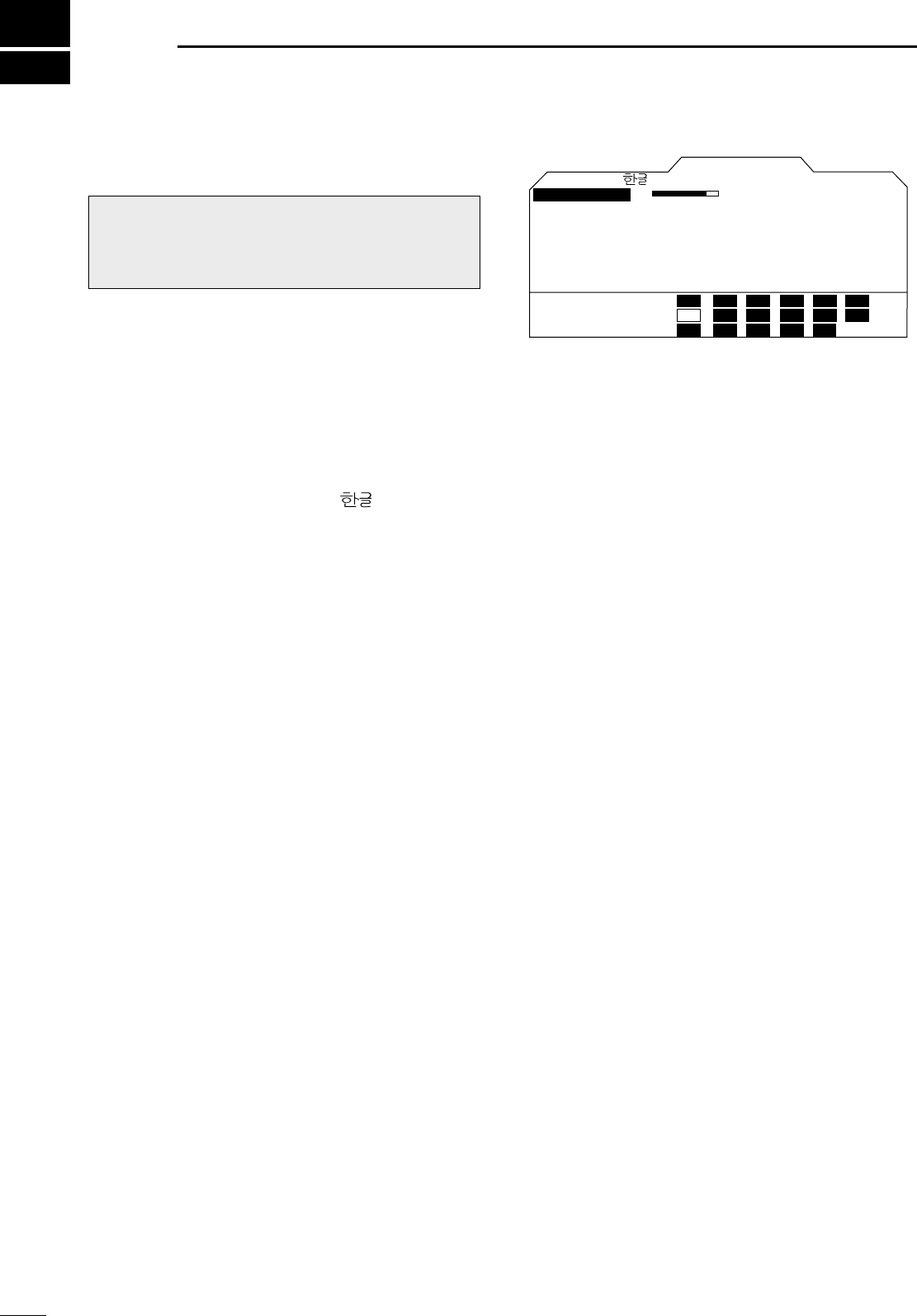
11
32
SERVICE MAN MENU
■Service man menu
To open the “SERVICE MAN” menu.
Push [MENU] several times to show the “SERVICE
MAN” menu.
■Select the language
Menu screens can be displayed in 2 different
languages.
Selectable languages; ENGLISH, (Hangul)
After opening the “SERVICE MAN” menu;
qPush [Ù] to show the present language.
wPush [Ω≈
] to select desired language, then push
[Ú] to continue the setting.
ePush [MENU] to exit the “SERVICE MAN” menu.
DTIMING ADJ.
•Corrects the distance.
DHDG ADJ.
•Adjusts the electronic heading line adjustment.
DSPD ADJ.
•Enter the pulse rate of the speed sensor.
DRANGE
•1⁄8, 1⁄4, 1⁄2, 3⁄4, 1, 1.5, 2, 3, 4, 6, 8, 12, 16, 24, 32, 36,
48* : Choose the selectable screen range.
*MR-1000TII only
DSETUP MEMORY
•The present setting value is displayed by pushing [≈],
then select the desired item from “RECALL” and
“SAVE” using with [Ú].
qPush [≈] to display “RECALL” and “SAVE”.
wPush [ÙÚ] to select “RECALL” or “SAVE”.
ePush [≈].
•“SURE ?” is displayed.
rPush [≈]to perform.
tPush [Ω]
to cancel
.
•When recall is performed without saving a setup, it
will become an initial value at the time of factory
shipments.
DOther readouts
•OUTPUT VOLTAGE
: Shows the voltage level for the
scanner unit from the display unit.
•HV (High voltage) : Shows the voltage level in the
high-voltage unit in the scanner
unit.
•MONITOR : Shows the voltage level for
checking the receiver unit opera-
tion.
•HEATER : Shows the heater current.
•MG :Shows the current level for the
Magnetron.
•TX TIME :Shows the total transmitted time.
SERVICE MAN
SPD ADJ.
HDG ADJ. 0.0
˚
HV
SETUP MEMORY RECALL
RANGE
24000 MONITOR
HEATER
5731.0H
TX TIME
30.0
OUTPUT
ENGLISH
VOLTAGE
SAVE MG
340
75
3.0
0.55
TIMING ADJ.
1/8 3/4 2 6
1/4 1 3 8
1/2 1.5 4 12
16
24
32
36
48
CAUTION: The SERVICE MAN MENU is available
for service purposes only. DO NOT change any set-
ting on the menu, otherwise the equipment may not
operate at it’s original performance.
MR-1000R2_T2_FCC.qxd 05.5.17 9:18 Page 32
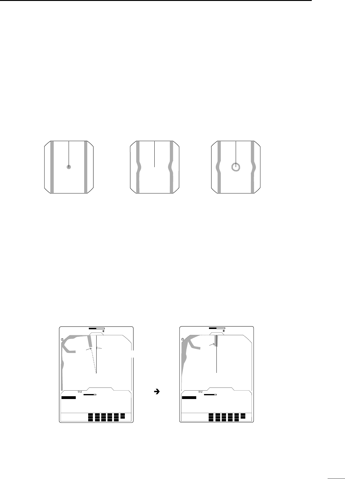
33
11
SERVICE MAN MENU
■TIMING adjustment
The system cable length affects the sweep timing.
When the cable length adjustment is not correct, a
straight target is shown as a curved echo. Thus, cable
length adjustment is necessary.
qPosition your boat near a straight target such as
breakwater, wharf, etc.
wPush [–] several times to select 1⁄8or 1⁄4NM range.
ePush [TX (SAVE)] to display the target on the
screen.
rPush [MENU], [Ú] and [≈] several times to display
the “SERVICE MAN” menu.
tPush [Ú] until the “TIMING ADJ.” section becomes
highlighted.
yPush [Ω≈
]to adjust the echo until it becomes
straight. (see below)
u
Push
[MENU]
to return to the normal screen.
Proper adjustment Improper, pulling inward Improper, pushing outward
■HDG adjustment
If the heading marker line differs from the exact bow
direction, correct the heading marker line as follows.
This function may be helpful when the scanner has not
been mounted exactly in the direction of the bow.
qLine up the bow of the boat with an identifiable tar-
get.
wPush [TX (SAVE)] to display the target on the
screen.
ePush [MENU], [Ú] and [≈] several times to display
the “SERVICE MAN” menu.
rPush [Ú] until the “HDG ADJ.” section becomes
highlighted.
tPush [Ω ≈] to adjust, until the target matches the
heading marker. (the difference can be read out on
the menu screen)
yPush [MENU] to return to the normal screen.
1
T.VECT
0.000NM
NM CURS
SOG H UP
000.0˚R
HDG
IR
ES
SERVICE MAN
SPD ADJ.
0.0
˚
HV
SETUP MEMORY
RANGE
24000 MONITOR
HEATER
5731.0H
TX TIME
30.0
OUTPUT
ENGLISH
VOLTAGE
MG
340
75
3.0
0.55
TIMING ADJ.
1/8 3/4 2 6 16 36
1/4 1 3 8 24
1/2 1.5 4 32
HDG ADJ.
1
T.VECT
0.000NM
NM CURS
SOG H UP
000.0˚R
HDG
IR
ES
SERVICE MAN
SPD ADJ.
10.0
˚
HV
SETUP MEMORY
RANGE
24000 MONITOR
HEATER
5731.0H
TX TIME
30.0
OUTPUT
ENGLISH
VOLTAGE
MG
340
75
3.0
0.55
TIMING ADJ.
1/8 3/4 2 6 16 36
1/4 1 3 8 24
1/2 1.5 4 32
HDG ADJ.
48
12
48
12
Push [Ω ≈]
Angle of difference
MR-1000R2_T2_FCC.qxd 05.5.17 9:18 Page 33
34
11 SERVICE MAN MENU
■SPD adjustment
qPush [MENU], [Ú] and [≈] several times to display
the “SERVICE MAN” menu.
wPush [Ú] until the “SPD ADJ.” section becomes
highlighted.
ePush [Ω≈
]to enter the pulse rate (pulse numbers
per one nautical mile) of the speed sensor unit.
rPush [MENU] to return to the normal screen.
■RANGE selection
qPush [MENU], [Ú] and [≈] to display the “SERVICE
MAN” menu.
wPush [Ú] until the “RANGE” section becomes high-
lighted.
ePush [Ù Ú] to choose the selectable screen ranges
with [+] or [–] on the display.
rPush [Ω]to skip from the range selection, or push
[≈] to cancel skipping.
tPush [MENU] to return to the normal screen.
Selectable ranges: 1⁄8, 1⁄4, 1⁄2, 3⁄4, 1, 1.5, 2, 3, 4, 6, 8,
12, 16, 24, 32, 36, 48* (NM)
*48 NM range is available for the MR-1000TII only.
SERVICE MAN
SPD ADJ.
HDG ADJ. 0.0
˚
HV
SETUP MEMORY
24000 MONITOR
HEATER
5731.0H
TX TIME
30.0
OUTPUT
ENGLISH
VOLTAGE
MG
340
75
3.0
0.55
TIMING ADJ.
1/8 3/4 2 6
1/4 1 3 8
1/2 1.5 4 12
16
24
32
36
48
RANGE
*1⁄4 NM range will be skipped.
MR-1000R2_T2_FCC.qxd 05.5.17 9:18 Page 34

■Error message list
*1Push any key to cancel the error message and beep tone. Turn the power OFF, then check the external data
cable connection.
*2An electricity failure may occur, turn the power OFF, then consult your dealer or service man.
*3Push any key to cancel the error message and beep tone.
*4Turn the power OFF, then check the system cable connections.
12
35
ERROR MESSAGE
Message Condition
BRG INPUT FAIL*1•The Azimuth signal is interrupted. An alarm tone is emitted within
5 sec. and the display reverts to H UP mode in approx. 1 min.
TRIG SIGNAL FAIL*1•If the TRIGGER signal is interrupted for more than 15 sec., an alarm
tone is emitted.
SHM SIGNAL FAIL*2•If the SHM signal is interrupted for more than 15 sec., an alarm tone is
emitted.
POSN INPUT FAIL*1•If the position signal is interrupted for more than 15 sec., an alarm tone
is emitted.
CHECK SCANNER CONNECTION*4•The system cable may not be connected properly.
MR-1000R2_T2_FCC.qxd 05.5.17 9:18 Page 35

Continued, reliable operation of the radar depends on how you care for your equipment. The simple maintenance
tips that follow can help you save time and money, and avoid premature equipment failures.
■Periodic maintenance
qKeep the equipment as clean as possible.
•Use a soft cloth to remove dirt, dust and water.
wCheck all hardware for loose screws, bolts, etc.
eCheck cables and terminal connections.
■Scanner unit maintenance
DCleaning
qWipe the surface of the scanner with a clean soft
cloth.
•DO NOT use strong solvents such as benzene or alco-
hol.
wCheck that there is no drift or caked salt.
•A heavy deposit of dirt or caked salt on the painted sur-
face of the upper scanner unit will cause a considerable
drop in radar performance.
eCheck for cracks or deterioration of the rubber
packing and replace it if necessary.
DPainting (MR-1000TII only)
To prevent the corrosion, paint the surface of the
scanner body (except the antenna unit) twice a year
or more.
DMounting
Check the mounting bolts of the scanner unit and
tighten if necessary.
■Display unit maintenance
DCleaning
Dirt on the CRT will, in time, leave a film of contami-
nates which tend to dim the picture.
qWipe the surface of the display unit with a clean soft
cloth.
•DO NOT use strong solvents such as benzene or alco-
hol.
wIf the picture is still dim, clean the CRT screen.
■Options
•OPC-1077 SYSTEM CABLE
Allows you to install the display unit and scanner up to 20 m (655⁄8ft) apart.
•OPC-1078 SYSTEM CABLE
Allows you to install the display unit and scanner up to 30 m (987⁄16 ft) apart.
WARNING: BE SURE the power is OFF before
working on the radar.
WARNING: BE SURE the power is OFF before
working on the radar.
WARNING: BE SURE the power is OFF before
performing any maintenance.
13
36
MAINTENANCE
MR-1000R2_T2_FCC.qxd 05.5.17 9:18 Page 36

14
37
SPECIFICATIONS
DDGeneral
•Minimum range : 25 m; 82 ft (when measurement range is 1⁄8NM)
•Maximum range : 36 NM (MR-1000RII; when measurement range is 36 NM)
48 NM (MR-1000TII; when measurement range is 48 NM)
•Measurement range : 1⁄8, 1⁄4, 1⁄2, 3⁄4, 1, 1.5, 2, 3, 4, 6, 8, 12, 16, 24, 32, 36,
48* (NM) *MR-1000TII only
•Preheat time :
90 sec.
•Connection length between display and scanner unit : 15 m; 497⁄32 ft (MR-1000RII),
20 m; 655⁄8ft (MR-1000TII, optional for MR-1000RII),
30 m; 987⁄16 (optional)
DDScanner unit
◆EX-2714 (Radome)
•Type : 2 feet Slotted Waveguide Array, enclosed in a radome.
•Rotation speed (typical) : 24 rpm, 36 rpm, 48 rpm (typ.)
•Beam width (typical) : Horizontal beam 4˚ (typ.)
Vertical beam 22˚ (typ.)
•Side lobe (typical) : –18 dB
•Polarization : Horizontal
•Transmission frequency : 9410 MHz ±30 MHz P0N
•Peak output power : 4 kW
•Pulse width : 80 nS/2880 Hz, 80 nS/2160 Hz, 250 nS/2160 Hz,
350 nS/2160 Hz, 900 nS/720 Hz.
•Mixer and Local Oscillator : Microwave Integrated Circuit
•Transmitting Tube : Magnetron MAF1421B
•Modulator : FET switching
•Duplexer : Circulator
•Tuning system : Automatic/manual selectable
•Intermediate frequency : 60 MHz
•IF Band width : 10 MHz, 3 MHz
•Dimensions : 607 (Ø)×243 (H) mm; 2329⁄32 (Ø)×99⁄16 (H) in
•Usable temperature range : –25˚C to +70˚C; –13˚F to 158˚F
•Relative Humidity : Less than 95% at 35˚C (+95˚F)
•Weight : Approx. 8 kg; 175⁄8lb (without cable)
◆EX-2780 (Open array)
• Type : 120 cm Slotted Waveguide Array
• Rotation speed (typical) : 24 rpm, 36 rpm, 48 rpm (typ.)
• Beam width (typical) : Horizontal beam 2˚ (typ.)
Vertical beam 25˚ (typ.)
• Side lobe (typical) : –24 dB
• Polarization : Horizontal
• Transmission frequency : 9410 MHz ±30 MHz P0N
• Peak output power : 4 kW
• Pulse width : 80 nS/2880Hz, 80 nS/2160 Hz, 250 nS/2160 Hz,
350 nS/2160 Hz, 900 nS/720 Hz.
•Mixer and Local Oscillator : Microwave Integrated Circuit
•Transmitting Tube : Magnetron MAF1421B
• Modulator : FET switching
• Duplexer : Circulator
• Tuning system : Automatic/manual selectable
• Intermediate frequency : 60 MHz
• IF Band width : 10 MHz, 3 MHz
• Diameter of rotation/height : 1205/381 mm; 477⁄16/15 in
•Usable temperature range : –25˚C to +70˚C; –13˚F to 158˚F
• Relative Humidity : Less than 95% at 35˚C (+95˚F)
• Weight : Approx. 17 kg; 3715⁄32 lb (without cable)
MR-1000R2_T2_FCC.qxd 05.5.17 9:18 Page 37

38
14 SPECIFICATIONS
DDDisplay unit
• CRT display : 10-inch green display
• Pixels : 640×480 dot
• CRT mounting : Vertical
• Input : NMEA 0183 format (for navigation receiver) ; N+1 for-
mat (flux gate compass sensor), AUX
• Power supply requirement : 10.2 to 42 V DC
• Power consumption (at wind velocity zero) : Approx. 60 W (MR-1000RII)
Approx. 70 W (MR-1000TII)
• Usable temperature range : –15˚C to +55˚C; +5˚F to 131˚F
• Relative humidity : Less than 95% at 35˚C (+95˚F)
• Dimensions :
269 (W)
×264 (H)×258 (D) mm
; 1019⁄32 (W)×1013⁄32 (H)×105⁄32 (D) in
•Weight : Approx. 6.5 kg; 145⁄16 lb
All stated specifications are subject to change without notice or obligation.
MR-1000R2_T2_FCC.qxd 05.5.17 9:18 Page 38

The following external bearing, speed, position and way point data is (are) required , when you use the radar func-
tions.
*1OG; Over ground, TW; Through the water
*2NMEA1 and NMEA2 connectors; See p. 24
•“HDT”, “HDM”, “RMC”, “GGA”, “GLL”, “VTG”, “WPL”, “GNS” and “BWC” are SENTENCES of the NMEA0183.
•If BRG INPUT is set to “GPS”, “RMC” of NMEA2 connector or COG (Course Over the Ground) of “VTG” a bow it
receives as a direction, even if there is no direction information (compass etc.) in NMEA1 connector, the screen
display of the North rise etc. is possible.
However, direction accuracy falls when the speed of a ship is set to 2 or less kts, or when exceeding 3 kts a bow
it does not receive as direction data. Moreo, the influence of measurement position accuracy or a current an actual
bow it may differ from a direction.
15
39
EXTERNAL DATA LIST
EXTERNAL DATA INPUT
NMEA1*2NMEA2*2
“HDT”, “HDM”“RMC”, “GGA”, “GLL”, “VTG”, “WPL”, “BWC”, LOG, “GNS”
N+1, AUX
FUNCTION DISPLAY BEARING SPEED POSITION WAY POINT
HEAD UP HU
COURSE UP CU Required
NORTH UP NU Required
TRUE MOTION OG*1TM Required “RMC”, “GGA” or “GLL”, “GNS”
TW*1TM Required LOG
SPEED DISPLAY OG*1SOG “RMC” or “VTG”
TW*1STW LOG
HEADING BEARING HDG Required
WAY POINT WPT Required “RMC”, “GGA” or “GLL”, “GNS”“WPL” or “BWC”
OWN VECTOR OG*1Required “RMC” or “VTG”
TW*1Required LOG
MOB MOB Required “RMC”, “GGA” or “GLL, “GNS”
ATA OG*1ATA Required “RMC” or “VTG”
TW*1ATA Required LOG
VRM/PI/WPT/MOB estimated OG*1“RMC” or “VTG”
time of arrival TW*1LOG
MAGNETIC VARIATION (AUTO)
“RMC” or “VTG”
MR-1000R2_T2_FCC.qxd 05.5.17 9:18 Page 39
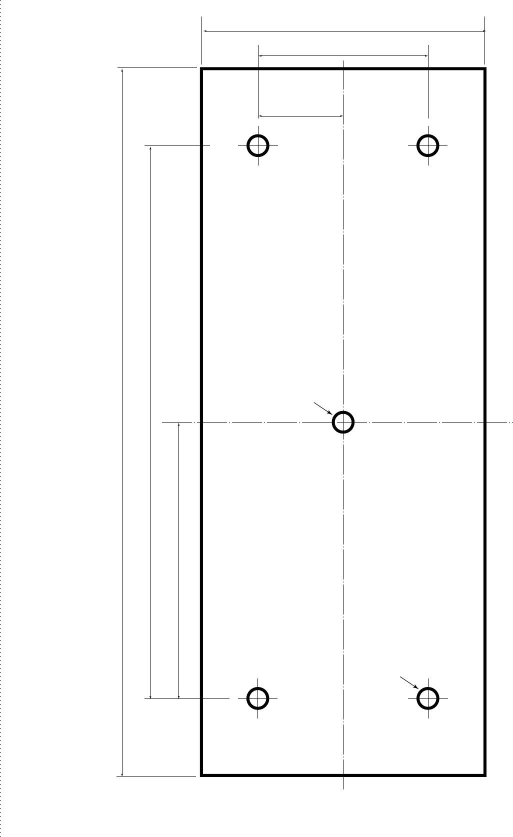
97.5 mm (327⁄32 in)
195 mm (711⁄16 in)
250 mm (927⁄32 in)
Radius is
3.5 mm
(1⁄8 in)
Radius is
3.5 mm
(1⁄8 in)
30 mm (13⁄16 in)
60 mm (23⁄8 in)
100 mm (315⁄16 in)
• SX-2713/2779
Display mounting bracket template
MR-1000R2_T2_FCC.qxd 05.5.17 9:18 Page 41
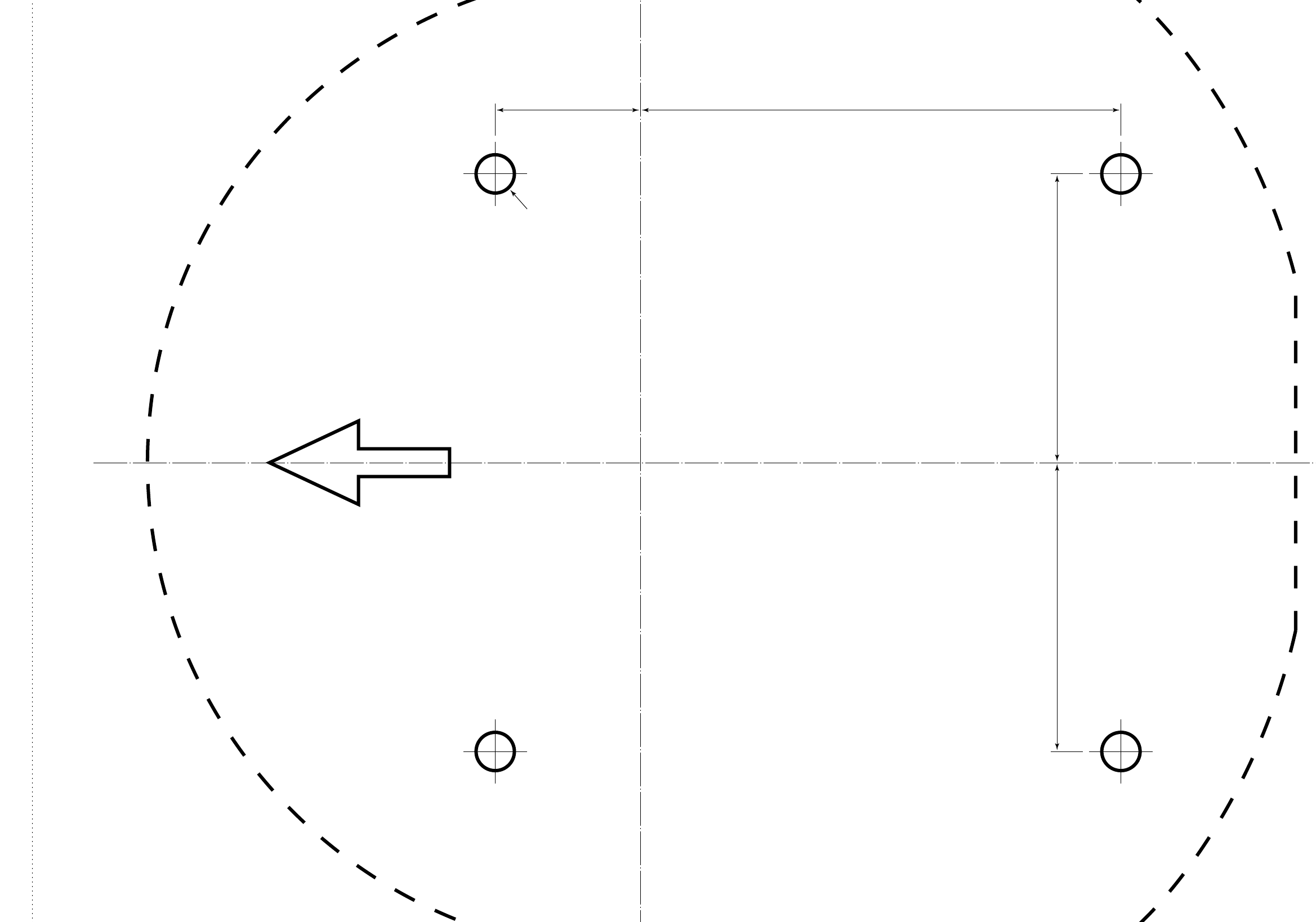
Ship’s bow direction
Radius is 6 mm
(1⁄4 in)
• EX-2714 Radome template
90.5 mm (39⁄16 in)
90.5 mm (39⁄16 in)
150.5 mm (515⁄16 in)45.5 mm (125⁄32 in)
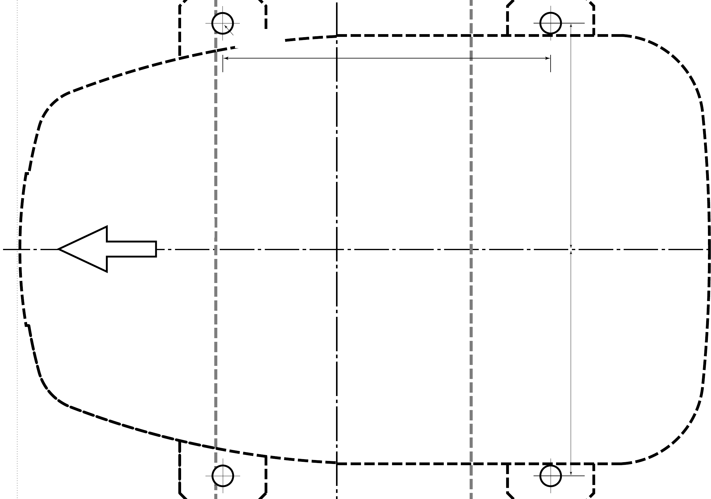
Ship’s bow direction
•EX-2780
Open array type
template
131 mm (55⁄32 in)
131 mm (55⁄32 in)
190 mm (715⁄32 in)
Radius is 6 mm
(1⁄4 in).

51
RADAR OPERATOR WARNING
Icom requires the radar operator to meet
the FCC Requirements for Radio Fre-
quency Exposure. A slotted waveguide
array antenna with gain not greater than
27 dBi must be mounted a minimum of 5.5
meters (measured from the lowest point of the
antenna) vertically above the main deck and all possi-
ble personnel. This is the minimum safe separation
distance estimated to meet all RF exposure compli-
ance requirements. This 5.5 meter distance is based
on the FCC Safe Maximum Permissible Exposure
(MPE) distance of 3.5 meters added to the height of an
adult (2 meters) and is appropriate for all vessels.
For watercraft without suitable structures, the antenna
must be mounted so as to maintain a minimum of 1
meter vertically between the antenna, (measured from
the lowest point of the antenna), to the heads of all per-
sons AND all persons must stay outside of the 3 5
meter MPE radius.
Do not transmit with radar and antenna when persons
are within the MPE radius of the antenna, unless such
persons (such as driver or radar operator) are shielded
from antenna field by a grounded metallic barrier. The
MPE Radius is the minimum distance from the an-
tenna axis that person should maintain in order to
avoid RF exposure higher than the allowable MPE
level set by FCC.
FAILURE TO OBSERVE THESE LIMITS MAY
ALLOW THOSE WITHIN THE MPE RADIUS TO EX-
PERIENCE RF RADIATION ABSORPTION WHICH
EXCEEDS THE FCC MAXIMUM PERMISSIBLE EX-
POSURE (MPE) LIMIT.
IT IS THE RESPONSIBILITY OF THE RADAR OP-
ERATOR TO ENSURE THAT THE MAXIMUM PER-
MISSIBLE EXPOSURE LIMITS ARE OBSERVED AT
ALL TIMES DURING RADAR TRANSMISSION. THE
RADAR OPERATOR IS TO ENSURE THAT NO BY-
STANDERS COME WITHIN THE RADIUS OF THE
MAXIMUM PERMISSIBLE EXPOSURE LIMITS.
Determining MPE Radius
THE MAXIMUM PERMISSIBLE EXPOSURE (MPE)
RADIUS HAS BEEN ESTIMATED TO BE A RADIUS
OF ABOUT 3.5 M PER OET BULLETIN 65 OF THE
FCC.
THIS ESTIMATE IS MADE ASSUMING THE MAXI-
MUM POWER OF THE RADAR AND ANTENNAS
WITH A MAXIMUM GAIN OF 27 dBi ARE USED FOR
A SHIP MOUNTED SYSTEM.
WARNING
MR-1000R2_T2_FCC.qxd 05.9.5 16:39 Page 51

1-1-32 Kamiminami, Hirano-ku, Osaka 547-0003, Japan
A-6450H-1US
Printed in Japan
© 2005 Icom Inc.
MR-1000R2_T2_FCC.qxd 05.5.17 9:18 Page 52