ICOM orporated 272103 UHF Transceiver User Manual IC F43GT GS
ICOM Incorporated UHF Transceiver IC F43GT GS
UserManual.wiki
>
ICOM orporated
>
272103 User Manual
>
Users Manual
Contents
1.
Users Manual
2.
Updated User Manual
Users Manual
Navigation menu
Upload a User Manual
Namespaces
Wiki Guide
HTML
PDF
Info
Views
User Manual
Discussion / Help
Navigation
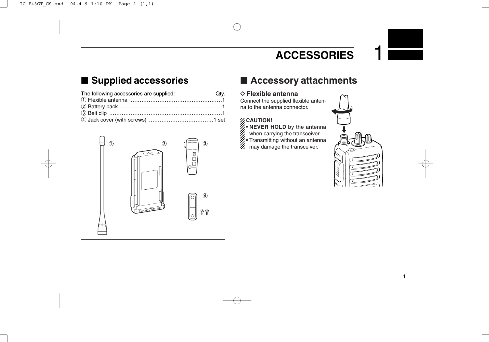
![31ACCESSORIESïJack coverAttach the jack cover when the optional speaker-microphoneis not used.qwqwTo attach the jack cover:qAttach the jack cover onthe [SP]/[MIC] jack.wTighten the screws.To detach the jack cover:qUnscrew the screws witha Phillips screwdriver.wDetach the jack cover forthe speaker-microphoneconnection.IC-F43GT_GS.qxd 04.4.9 1:10 PM Page 3 (1,1)](https://usermanual.wiki/ICOM-orporated/272103.Users-Manual/User-Guide-470426-Page-7.png)
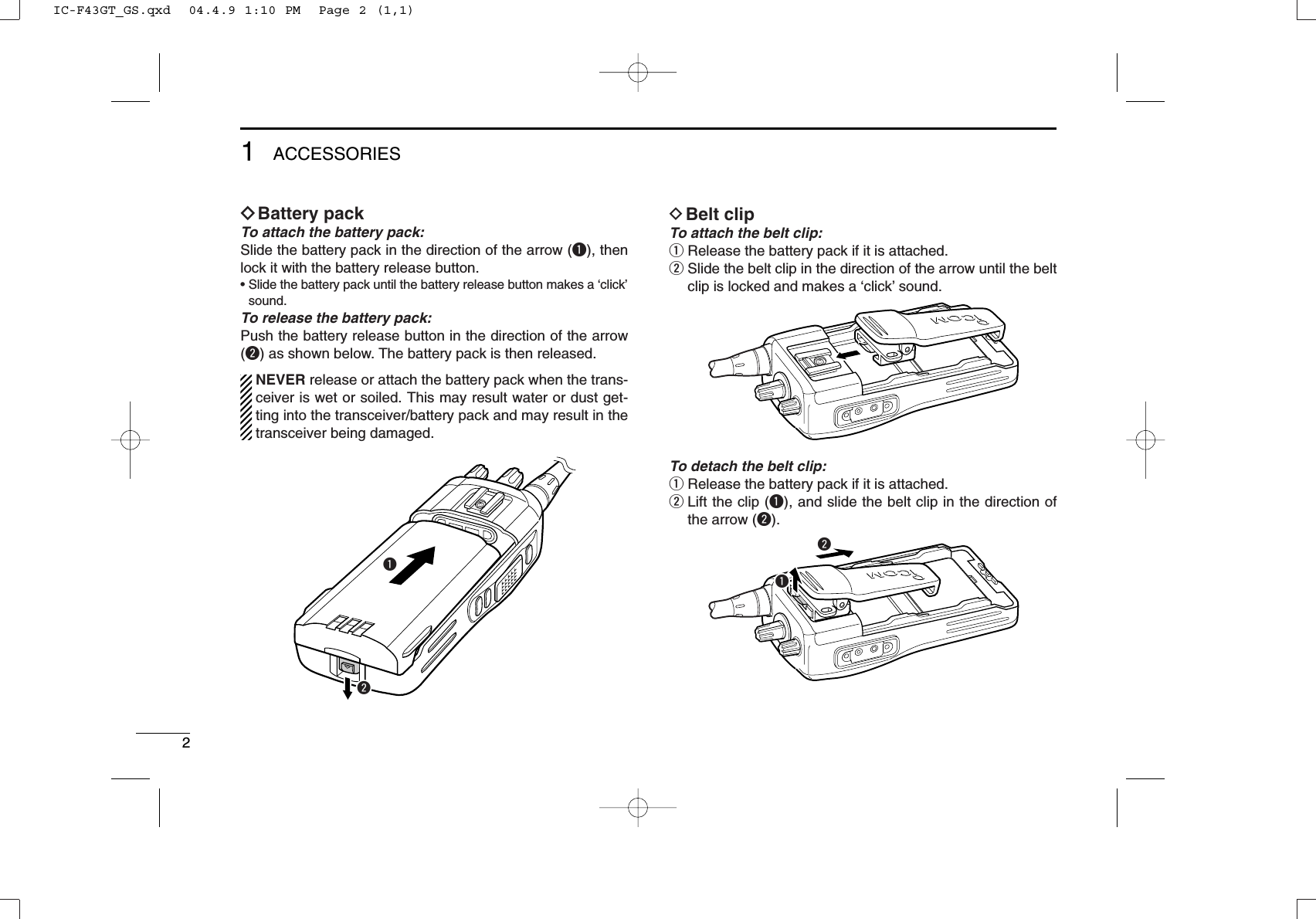
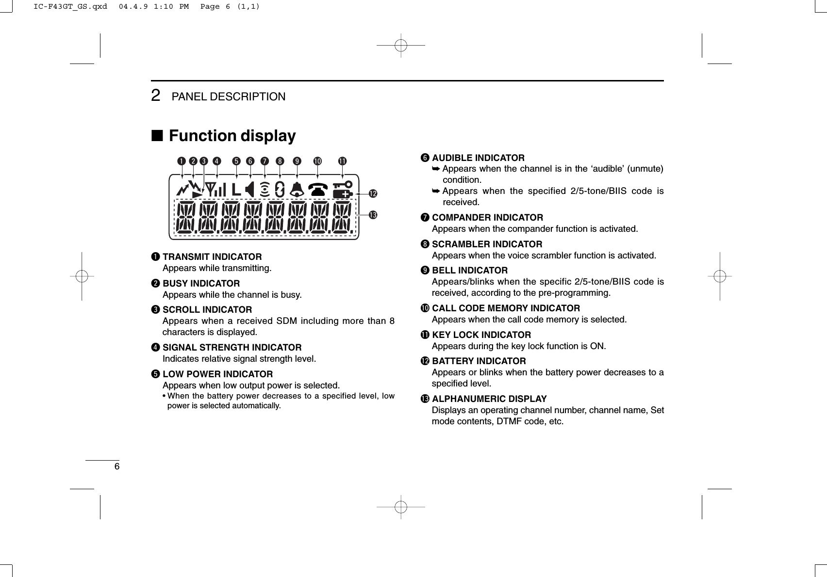
![42PANEL DESCRIPTION■Front panelqROTARY SELECTORRotate to select the pre-programmed memory channels orthe operating bank.(Depending on the pre-setting)wVOLUME CONTROL [VOL]Rotate to turn the power ON and adjusts the audio level.eDEALER-PROGRAMMABLE KEY [RED]Desired function can be programmed independently byyour dealer. (p. 7)r[SP]/[MIC] JACKConnect the optional speaker-microphone. tFUNCTION DISPLAYDisplays a variety of information such as an operatingchannel number/name, 2/5-tone code, DTMF numbers,selected function, etc.yDEALER-PROGRAMMABLE KEYS [P0] to [P3]Desired functions can be programmed independently byyour dealer. (p. 7)[SP]/[MIC] jack coverNOTE: Attach the [SP]/[MIC] jack cover when the optional speaker-microphone is not used. (See p. 3 for details)itrqeuywo!0!110-keypad versionIC-F43GT_GS.qxd 04.4.9 1:10 PM Page 4 (1,1)](https://usermanual.wiki/ICOM-orporated/272103.Users-Manual/User-Guide-470426-Page-8.png)
![52PANEL DESCRIPTIONu10-KEYPAD (Depending on version)The keypad allows you to enter digits to:• Select memory channels• Select tone channels• Select DTMF codes (during transmit)• Set TX codes• Set SmarTrunk II™/SmarTrunk 3G codes• Set BIIS status number• Input text message for SDM operation• Start up with the passcodeiUP/DOWN KEYS➥Push to select an operating channel.➥Push to select a TX code channel after pushing [TX CODE CH SELECT].➥Push to select a DTMF channel after pushing [DTMF].➥Push to select a scan group after pushing and holding[SCAN].➥Push to select a BIIS code, status number or SDM afterpushing [DIGITAL].*Desired functions can be programmed independently by yourdealer. (p. 7)oPTT SWITCH [PTT]➥Push and hold to transmit; release to receive.➥Push to transmit the call during MSK operation, depend-ing on the setting.!0 MONITOR KEY➥ Mute and release the CTCSS (DTCS) or 2-tone squelchmute. Open any squelch/deactivate any mute whilepushing this key. (LMR operation only)➥ Activates one of (or two of) the following functions oneach channel independently.(PMR or BIIS PMR operation only)• Push and hold the key to unmute the channel (audio isemitted; ‘audible’condition).• Push the key to toggle the mute and unmute conditions(toggles ‘audible’and ‘inaudible’).• Push the key to mute the channel (sets to ‘inaudible’only).• Push the key to unmute the channel (sets to ‘audible’only).• Push the key after communication is finished to send a ‘resetcode.’• Push the key after communication is finished to send a ‘cleardown code’during BIIS operation on an MSK channelNOTE: The unmute condition (‘audible’conditions)may automatically return to the mute condition(‘inaudible’condition) after a specified period.*Desired function can be programmed independently by yourdealer. (p. 7)!1 ANTENNA CONNECTORConnects the supplied antenna.IC-F43GT_GS.qxd 04.4.9 1:10 PM Page 5 (1,1)](https://usermanual.wiki/ICOM-orporated/272103.Users-Manual/User-Guide-470426-Page-9.png)
![72PANEL DESCRIPTION■Programmable function keysThe following functions can be assigned to [UP], [DOWN],[P0], [P1], [P2], [P3], [RED] and [MONITOR] programmablefunction keys. Consult your Icom dealer or system operator for details con-cerning your transceivers programming.If the programmable function names are bracketed in the fol-lowing explanations, the specific key is used to activate thefunction depends on the programming.CH UP AND DOWN KEYS➥Push to select an operating channel.➥Push to select a transmit code channel after pushing [TXCode CH Select].➥Push to select a DTMF channel after pushing [DTMFAutodial].➥Push to select a scan group after pushing and holding[Scan A Start/Stop]/[Scan B Start/Stop].➥Push to select a BIIS code, status number or SDM afterpushing [Digital].BANK SELECT KEYPush this key, then push [CH Up] or [CH Down] to select thedesired bank.SCAN A KEY➥This key’s operation depends on the Power ON Scan set-ting.When the power ON scan function is turned OFF;Push to start and cancel scanning operation. In case oftransmission during scan, cancels scanning.When the power ON scan function is turned ON;Push to pause scanning. Scanning resumes after passinga specified time period. In case of transmission duringscan, pauses scanning. Scanning resumes after passinga specified time period specified.➥Push and hold this key for 1 sec. to indicate the scangroup, then push [CH Up] or [CH Down] to select thedesired group.SCAN B KEY➥Push to start and cancel scanning operation. In case oftransmission during scan, pauses scanning. Scanningresumes after passing a specified time period. ➥Push and hold this key for 1 sec. to indicate the scangroup, then push [CH Up] or [CH Down] to select thedesired group.IC-F43GT_GS.qxd 04.4.9 1:10 PM Page 7 (1,1)](https://usermanual.wiki/ICOM-orporated/272103.Users-Manual/User-Guide-470426-Page-11.png)
![82PANEL DESCRIPTIONSCAN TAG KEYPush to add or delete the selected channel to the scan group.PRIORITY CHANNEL KEYS➥Push to select Priority A or Priority B channel.➥Push and hold [Prio A (Rewrite)] to rewrite the Prio A chan-nel.MR-CH 1/2/3/4 KEYSPush to select an operating channel directly.MONITOR KEY➥Mute and release the CTCSS (DTCS) or 2-tone squelchmute. Open any squelch/deactivate any mute while push-ing this key. (LMR operation only)➥Activates one of (or two of) the following functions on eachchannel independently: (PMR or BIIS PMR operation only)• Push and hold to un-mute the channel (audio is emitted;‘Audible’condition).• Push to mute the channel (sets to ‘Inaudible’only).• Push to un-mute the channel (sets to ‘Audible’only).• Push after the communication is finished to send a ‘resetcode’.NOTE: The un-mute condition (‘Audible’condition) mayautomatically return to the mute condition (‘Inaudible‘condition) after a specified period.LOCK KEYPush and hold to electronically lock all programmable keysexcept the following:[Call] (incl. Call A and Call B), [Moni(Audi)] and [Emergency].OUTPUT POWER SELECTION KEYPush to select the transmit output power temporarily or per-manently, depending on the pre-setting.•Ask your dealer for the output power level for each selection.C.TONE CHANNEL ENTER KEYPush to select the continuous tone channel using [CH Up]/[CH Down] to change the tone frequency/code set-ting after pushing this key for permanent operation.TALK AROUND KEYTurn the talk around function ON and OFF.•The talk around function equalizes the transmit frequency to thereceive frequency for transceiver-to-transceiver communication.WIDE/NARROW KEYPush to toggle the IF bandwidth between wide and narrow.• The wide passband width can be selected from 25.0 or 20.0 kHzusing the CS-F33G CLONING SOFTWARE. (PMR or BIIS PMR opera-tion only) Ask your Dealer for details.IC-F43GT_GS.qxd 04.4.9 1:10 PM Page 8 (1,1)](https://usermanual.wiki/ICOM-orporated/272103.Users-Manual/User-Guide-470426-Page-12.png)
![92PANEL DESCRIPTIONDTMF AUTODIAL KEY➥Push to enter the DTMF channel selection mode. Thenselect the desired DTMF channel using [CH Up]/[CH Down]keys.➥After selecting the desired DTMF channel, push this key totransmit the DTMF code.DTMF RE-DIAL KEYPush to transmit the last-transmitted DTMF code.CALL KEYSPush to transmit a 2/5-tone/BIIS ID code.•Call transmission is necessary before you call another stationdepending on your signalling system.•[Call A] and/or [Call B] may be available when your system employsselective ‘Individual/Group’calls. Ask your dealer which call isassigned to each key.EMERGENCY KEYS➥Push and hold to transmit an emergency call.➥When [Emergency Single (Silent)] or [Emergency Repeat(Silent)] is pushed, an emergency call is transmitted withouta beep emission and LCD indication change.• If you want to cancel the emergency call, push (or push andhold) the key again before transmitting the call.• The emergency call is transmitted one time only or repeatedlyuntil receiving a control code depending on the pre-setting.TX CODE ENTER KEY (PMR or BIIS PMR operation only)Push to enter the direct ID code edit mode, for both 5-toneand MSK. Then set the desired digit using [CH Up]/[CHDown]/[TX Code CH Up]/[TX Code CH Down] or 10-keypad.*(p. 14)*Depending on versionTX CODE CHANNEL SELECT KEY➥Push to enter the direct ID code channel selection mode.Then set the desired channel using [CH Up]/[CHDown]/[TX Code CH Up] or [TX Code CH Down]. (p. 13)➥While in ID code channel selection mode, push for 1 sec. toenter the ID code edit mode for 5-tone and MSK. Then setthe desired digit using [CH Up]/[CH Down]/[TX Code CHUp]/[TX Code CH Down] or 10-keypad.* (p. 14)*Depending on versionTX CODE CHANNEL UP/DOWN KEYSPush to select a TX code channel directly.ID MEMORY READ KEY (PMR or BIIS PMR operation only)➥Recalls detected ID codes.•Push this key, then push [CH Up]/[CH Down] for selection.•Up to 5 ID’s are memorized.➥Push and hold to erase the selected memorized ID’s.VOICE SCRAMBLER FUNCTIONPush to toggle the voice scrambler function ON and OFF.IC-F43GT_GS.qxd 04.4.9 1:10 PM Page 9 (1,1)](https://usermanual.wiki/ICOM-orporated/272103.Users-Manual/User-Guide-470426-Page-13.png)
![102PANEL DESCRIPTIONCOMPANDER KEYPush to toggle the compander function ON and OFF. The compander function reduces noise components from thetransmitting audio to provide clear communication.USER SET MODE KEY➥Push and hold to enter user set mode.• During user set mode, push this key to select an item, and push[CH Up]/[CH Down] to change the value or condition.➥Push and hold this key again to exit user set mode.OPT OUT KEYSPush to control the optional unit connector output signal level.DIGITAL KEY (BIIS operation only)➥Push to select the call ID list, transmit message and stand-by condition. Toggles between queue channel andreceived message record indication after queue channel isselected.➥Push and hold to select queue channel indication.STATUS UP/DOWN KEYS (BIIS operation only)➥While in the standby condition, push to display the trans-mit status indication and select a status number.➥When a received SDM is displayed, push to cancel theautomatic scroll and scroll the message manually.➥When an SDM that contains more than 8 characters is dis-played, push to scroll the message manually.DFor SmarTrunk operation onlyTRUNKING GROUP KEYPush to select the Trunking group.TURBO SPEEDIAL A/B/C/D KEYSPush to automatically dial a commonly used number with onepush.CALL/CLEAR-DOWN KEYSFunctions as [M] and [#] keys on the 10-keypad.• Push [M] for call, push [#] for clear-down.TRUNKING CALLER ID KEYPush [Trunking Caller ID SW] to display the received IDrecord in sequence (while in SmarTrunk 3G operation).IC-F43GT_GS.qxd 04.4.9 1:10 PM Page 10 (1,1)](https://usermanual.wiki/ICOM-orporated/272103.Users-Manual/User-Guide-470426-Page-14.png)
![113BASIC OPERATION■Turning power ONqRotate [VOL] to turn the power ON.wIf the transceiver is programmed for a start up passcode,input the digit codes as directed by your dealer.• 10-keypad can be used for password input depending on ver-sion:• The keys in the table below can be used for password input:• The transceiver detects numbers in the same block as identical.Therefore “01234” and “56789” are the same.eWhen the “PASSWORD” indication does not clear afterinputting 4 digits, the input code number may be incorrect.Turn the power off and start over in this case.■Channel selectionSeveral types of channel selections are available. Methodsmay differ according to your system set up.NON-BANK TYPE:Push [UP] or [DOWN], or rotate [ROTARY SELECTOR]* toselect the desired operating channel, in sequence; or, pushone of [MR-CH 1] to [MR-CH 4] keys to select a channeldirectly.• Up to 16 pre-programmed channels can be selected via [ROTARYSELECTOR].*BANK TYPE:Push [BANK], then push [UP] or [DOWN] or rotate [ROTARYSELECTOR]* to select the desired bank.AUTOMATIC SCAN TYPE:Channel setting is not necessary for this type. When turningpower ON, the transceiver automatically starts scanning.Scanning stops when receiving a call.*Depending on the pre-setting.KEYNUMBER 0549382716DOWNIC-F43GT_GS.qxd 04.4.9 1:10 PM Page 11 (1,1)](https://usermanual.wiki/ICOM-orporated/272103.Users-Manual/User-Guide-470426-Page-15.png)
![123BASIC OPERATION■Call procedureWhen your system employs tone signaling (excluding CTCSSand DTCS), the call procedure may be necessary prior to voicetransmission. The tone signalling employed may be a selec-tive calling system which allows you to call specific station(s)only and prevent unwanted stations from contacting you.qSelect the desired TX code channel or 2/5-tone codeaccording to your System Operator’s instructions.• This may not be necessary depending on programming.• Refer to pgs. 13 or 14 for selection.wPush the call key (assigned to one of the dealer program-mable keys: [Up], [Down], [P0], [P1], [P2], [P3],[Emergency] and [Monitor]) or [PTT].eAfter transmitting a 2/5-tone code, the remainder of yourcommunication can be carried out in the normal fashion.■Receiving and transmittingNOTE: Transmitting without an antenna may damage thetransceiver. See p. 1 for antenna attachment.Receiving:qRotate [VOL] to turn the power ON.wPush [UP] or [DOWN], or rotate [ROTARY SELECTOR]*to select a channel, in sequence.*Depending on the pre-setting.eWhen receiving a call, adjust the audio output level to acomfortable listening level.Transmitting:Wait for the channel to become clear to avoid interference.qWhile pushing and holding [PTT], speak into the micro-phone at a normal voice level.wRelease [PTT] to return to receive.IMPORTANT: To maximize the readability of your signal;1. Pause briefly after pushing [PTT].2. Hold the microphone 5 to 10 cm (2 to 4 inches) fromyour mouth, then speak into the microphone at a normalvoice level.Selective calling Non-selective callingIC-F43GT_GS.qxd 04.4.9 1:10 PM Page 12 (1,1)](https://usermanual.wiki/ICOM-orporated/272103.Users-Manual/User-Guide-470426-Page-16.png)
![133BASIC OPERATIONDTransmitting notes• Transmit inhibit functionThe transceiver has several inhibit functions which restricttransmission under the following conditions:- The channel is in mute condition (‘Inaudible’condition; “” does not appear.)- The channel is busy.- Un-matched (or matched) CTCSS is received.- The selected channel is a ‘receive only’channel.• Time-out timerAfter continuous transmission for the pre-programmed timeperiod, the time-out timer is activated, causing the transceiv-er to stop transmitting.• Penalty timerOnce the time-out timer is activated, transmission is furtherinhibited for a period determined by the penalty timer.DTX code channel selectionIf the transceiver has [TX Code CH Select] assigned to it,indication can be toggled between the operating channelnumber (or name) and TX code channel number (or name).When the TX code channel number (or name) is displayed,[UP]/[DOWN] selects the TX code channel.TO SELECT A TX CHANNEL:qPush [TX Code CH Select]— a TX code channel appears.wPush [UP] or [DOWN] to select the desired TX code chan-nel.ePush [Call] (or [PTT] during MSK operation) to transmit theselected TX code.rPush [TX Code CH Select] again to return to the operat-ing channel number indication.FOR TX CODE CHANNEL TYPE:If the transceiver has a [TX Code CH Up] or [TX Code CHDown] key assignment, the programmed TX code channelcan be selected directly.IC-F43GT_GS.qxd 04.4.9 1:10 PM Page 13 (1,1)](https://usermanual.wiki/ICOM-orporated/272103.Users-Manual/User-Guide-470426-Page-17.png)
![143BASIC OPERATIONDTX code number edit(PMR or BIIS PMR operation only)If the transceiver has [TX Code CH Select] or [TX CodeEnter] assigned to it, TX code contents can be edited withinthe allowable digits.TO EDIT A TX CODE VIA [TX CODE CH SELECT] KEY:qPush [TX Code CH Select] to enter the TX code channelselection mode.• Select the desired channel using [UP] or [DOWN] if necessary.wPush [TX Code CH Select] for 1 sec. to enter the TX codeedit mode.ePush [TX Code CH Select] to select the desired digit to beedited.rSet the desired digit using [UP], [DOWN], [TX Code CHUp], [TX Code CH Down] or 10-keypad.**Depending on version.tPush [TX Code CH Select] to set the digit. The editabledigit will move to the right automatically.• When the 10-keypad is used to set, the editable digit will move tothe right automatically without pushing [TX Code CH Select].yRepeat rand tto input all allowable digits.uPush [Call] or [PTT] to transmit the edited TX code.TO EDIT A TX CODE VIA [TX CODE ENTER] KEY:qSelect the desired TX code channel via [TX Code CH Up]or [TX Code CH Down].wPush [TX Code Enter] to enter the TX code edit mode.ePush [TX Code Enter] to select the desired digit to be edit-ed.rSet the desired digit using [UP], [DOWN], [TX Code CHUp] or [TX Code CH Down] or 10-keypad*.*Depending on version.tPush [TX Code Enter] to set the digit. The editable digit willmove to the right automatically.• When the 10-keypad is used to set, the editable digit will move tothe right automatically without pushing [TX Code CH Select].yRepeat rand tto input all allowable digits.uPush [Call] or [PTT] to transmit the edited TX code.IC-F43GT_GS.qxd 04.4.9 1:10 PM Page 14 (1,1)](https://usermanual.wiki/ICOM-orporated/272103.Users-Manual/User-Guide-470426-Page-18.png)
![153BASIC OPERATIONDDTMF transmissionIf the transceiver has [DTMF Autodial] assigned to it, the auto-matic DTMF transmission function is available. Up to 8 DTMFchannels are available.TO SELECT A TX CODE:qPush [DTMF Autodial]— a DTMF channel appears.wPush [UP] or [DOWN] to select the desired DTMF chan-nel.ePush [DTMF Autodial] to transmit the DTMF code in theselected DTMF channel.■User set modeUser set mode is accessed with [User Set Mode] and allowsyou to set seldom-changed settings. In this case you can“customize” the transceiver operation to suit your preferencesand operating style.Entering the user set mode:qPush and hold [User Set Mode] to enter user set mode.Push [User Set Mode] momentarily to select the item. Then push [UP] or [DOWN] to set the desired level/condi-tion.• Available set mode functions are Backlight, Beep, SQL Level,Mic Gain and Battery Voltage.wPush and hold [User Set Mode] to exit user set mode.■Scrambler functionThe voice scrambler function provides private communicationbetween stations. The frequency inversion type is equippedto all versions, moreover, the optional Rolling or Non-rollingtype can be available.qPush [Scrambler] to turn the scrambler function ON.• “” appears.wPush [Scrambler] again to turn the scrambler functionOFF.• “” disappears.IC-F43GT_GS.qxd 04.4.9 1:10 PM Page 15 (1,1)](https://usermanual.wiki/ICOM-orporated/272103.Users-Manual/User-Guide-470426-Page-19.png)
![164BIIS OPERATION■Default settingThe following functions are assigned to each programmablekey as the default. However, the assigned function can bechanged by your dealer. Ask your dealer for details.NOTE: [TX Code Enter] must be assigned to any key.[P0]; Call : Push to transmit a 5-tone/BIIS callwhen the selected channel is a 5-tone or MSK channel, respectively.[P1]; Digital : Push to select the call list ID/trans-mit message, or to display thereceive message record for selec-tion.[P3]; TX Code Enter : Push to enter the direct ID code editmode for both 5-tone and MSK.[UP]/[DOWN]; CH Up/Down: While in the standby condition,selects the operating channel.After pushing [Digital] or [TX CodeCH Select], selects call list or TXcode channel, respectively.[MONITOR]; Moni(Audi): Push this key after the communica-tion to send a ‘Clear down’signalduring MSK channel operation.[P2]/[RED]; Null : No function is assigned.■Receiving a callDDIndividual callqWhen an individual call is received;•Beeps sound.•“ ” appears and the mute is released.•The programmed text message (e.g.“”) and the callingstation ID (or text) is displayed alternately, depending on the set-ting.•“ ” appears or blinks depending on the setting.wPush and hold [PTT], then speak into the microphone at anormal voice level.•“ ” indicator appears.eRelease [PTT] to return to receive.•“ ” appears while receiving a signal.rTo finish the conversation, push [MONITOR] (Moni(Audi))to send the ‘Clear down’signal. •Either station can send a ‘Clear down’signal.•“ ” is displayed for 2 sec. (approx.).•“ ” disappears and the transceiver returns to the standby condi-tion.Appears or blinksAppearsIC-F43GT_GS.qxd 04.4.9 1:10 PM Page 16 (1,1)](https://usermanual.wiki/ICOM-orporated/272103.Users-Manual/User-Guide-470426-Page-20.png)
![174BIIS OPERATIONDDGroup callqWhen a group call is received;•Beeps sound.•“ ” appears and the mute is released.•The programmed text message (e.g.“”) and the callingstation ID (or text) is displayed alternately, depending on the set-ting.•“ ” appears or blinks depending on the setting.wPush and hold [PTT], then speak into the microphone at anormal voice level.NOTE: Only one station is permitted to speak.•“ ” appears.eRelease [PTT] to return to receive.•“ ” appears while receiving a signal.rTo finish the conversation, push [MONITOR] (Moni(Audi))to send the ‘Clear down’signal.•Either station can send a ‘Clear down’signal.•“ ” is displayed for 2 sec. (approx.)•“ ” disappears and the transceiver returns to the standby condi-tion.DDDisplaying the received call record— Queue indicationThe transceiver memorizes the calling station IDs for record.Up to 3 calls can be memorized, and the oldest call record iserased when a 4th call is received. However, once the trans-ceiver is powered OFF, the all records are cleared.qPush [P1] (Digital) for 1 sec.•Displays following indication.When a record is availableWhen no record is availablewPush [UP] or [DOWN] to select the desired call.ePush [P1] (Digital) for 1 sec. again to return to the standbycondition.•When no operation is performed for 30 sec., the transceiverreturns to the standby condition automatically.Appears or blinksAppearsIC-F43GT_GS.qxd 04.4.9 1:10 PM Page 17 (1,1)](https://usermanual.wiki/ICOM-orporated/272103.Users-Manual/User-Guide-470426-Page-21.png)
![184BIIS OPERATION■Transmitting a callTotal of a 3 ways for code selection are available—selectingthe call code from memory, entering the call code from thekeypad and calling back from the queue channel record.DDUsing call memoryqWhile in the standby condition, push [P1] (Digital) to enterthe call code memory channel selection mode.•“ ” appears.wPush [UP] or [DOWN] to select the desired call code.ePush [P0] (Call) or [PTT]* to call.*PTT call can be made only when PTT call capability is permitted.NOTE: When no answer back is received, the trans-ceiver repeats the call 3 times (default) automatically,and “”is displayed during each call. However, anerror beep sounds and “”is displayed when noanswer back is received after the calls.rPush [PTT] to transmit; release to receive.tPush [MONITOR] (Moni(Audi)) to send the ‘Clear down’signal.DDCalling back from the queue channelqWhile in the standby condition, push [P1] (Digital) for1 sec. to enter the queue memory channel selection mode.wPush [UP] or [DOWN] to select the desired record.ePush [P0] (Call) or [PTT]* to call.*PTT call can be made only when PTT call capability is permitted.NOTE: When no answer back is received, the trans-ceiver repeats the call 3 times (default) automatically,and “”is displayed during each call. However, anerror beep sounds and “”is displayed when noanswer back is received after the calls.rPush [PTT] to transmit; release to receive.tPush [MONITOR] (Moni(Audi)) to send the ‘Clear down’signal.Call code text is displayed.AppearsIC-F43GT_GS.qxd 04.4.9 1:10 PM Page 18 (1,1)](https://usermanual.wiki/ICOM-orporated/272103.Users-Manual/User-Guide-470426-Page-22.png)
![194BIIS OPERATIONDDDirect code entryqWhile in the standby condition, push [P3] (TX Code Enter)to enter the TX code edit mode.•Editable code digit blinks.wPush [P3] (TX Code Enter) to select the desired digit to beedited.•Editable digit differs according to the setting.eSet the desired digit using [CH Up]/[CH Down]/[TX CodeCH Up]/[TX Code CH Down] or 10-keypad.**Depending on versionrPush [P3] (TX Code Enter) to set the digit, then theeditable digit will move to the right automatically.• When the 10-keypad is used to set, the editable digit will move tothe right automatically without pushing [P3] (TX Code Enter).tRepeat eand rto input all allowable digits.yPush [P0] (Call) or [PTT]* to call.*PTT call can be made only when PTT call capability is permitted.NOTE: When no answer back is received, the trans-ceiver repeats the call 3 times (default) automatically,and “”is displayed during each call. However, anerror beep sounds and “”is displayed when noanswer back is received after the calls.uPush [PTT] to transmit; release to receive.iPush [MONITOR] (Moni(Audi)) to send the ‘Clear down’signal.For your informationWhen the “UpDate” setting for the call code is enabled, theset code is overwritten into the call code memory.IC-F43GT_GS.qxd 04.4.9 1:10 PM Page 19 (1,1)](https://usermanual.wiki/ICOM-orporated/272103.Users-Manual/User-Guide-470426-Page-23.png)
![204BIIS OPERATION■Receiving a messageDDReceiving a status messageqWhen a status message is received;• Beeps sound.• The calling station ID (or text) and the status message is dis-played alternately, depending on the setting.wPush [MONITOR] (Moni(Audi)) to return to the standbycondition.NOTE: Only the calling station ID (or text) is displayed (nomessage is displayed alternately) when the scroll timer isset to ‘OFF.’In this case, push [Status Up]/[Status Down]to display the status message manually.DDReceiving an SDMqWhen an SDM is received;• Beeps sound.• The calling station ID (or text) and the SDM is displayed alter-nately, depending on the setting.wWhen the received SDM includes more than 8 characters,“” appears and the message scrolls automatically, whenthe automatic scroll function is activated.• Push [Status Up]/[Status Down] to scroll the message manually.ePush [MONITOR] (Moni(Audi)) to return to the standbycondition.IC-F43GT_GS.qxd 04.4.9 1:10 PM Page 20 (1,1)](https://usermanual.wiki/ICOM-orporated/272103.Users-Manual/User-Guide-470426-Page-24.png)
![214BIIS OPERATIONDDReceived message selectionThe transceiver memorizes the received messages forrecord. Up to 6 messages for status and SDM, or 95 charac-ter SDM’s can be memorized. The oldest message is erasedwhen the 7th message is received. However, once the trans-ceiver is powered OFF, all messages are cleared.qPush [P1] (Digital) for 1 sec.•Displays queue memory.wPush [P1] (Digital) momentarily.•Displays message memory.When a message is availableWhen no message is availableePush [UP] or [DOWN] to select the desired message.•When selecting the SDM that includes more than 8 characters,“” appears and the message scrolls automatically, when theautomatic scroll function is activated.• Push [Status Up]/[Status Down] to scroll the message manually.rPush [P1] (Digital) for 1 sec. again to return to the standbycondition.•When no operation is performed for 30 sec., the transceiverreturns to the standby condition automatically.IC-F43GT_GS.qxd 04.4.9 1:10 PM Page 21 (1,1)](https://usermanual.wiki/ICOM-orporated/272103.Users-Manual/User-Guide-470426-Page-25.png)
![224BIIS OPERATION■Transmitting a statusDDGeneralThe status message can be selected with the programmedtext, and the message text is also displayed on the functiondisplay of the called station.Up to 24 status types (1 to 24) are available, and the statusmessages 22 and 24 have designated meanings.Status 22: Emergency*Status 24: GPS request*The status 22 can also be used as a normal status message bydisabling the designated meaning. However, the status 24 is fixed.The status call can be sent with both individual and groupcalls.DDTransmitting a statusqWhile in the standby condition, push [P1] (Digital), thenpush [UP] or [DOWN] to select the desired station/groupcode.wPush [P1] (Digital) again, then push [UP] or [DOWN] toselect the desired status message.Or, you can select the desired status message using[Status Up]/[Status Down] key directly.ePush [P0] (Call) or [PTT]* to transmit the status messageto the selected station/group.*PTT call can be made only when PTT call capability is permitted.•2 beeps will sound and the transceiver returns to the standbycondition automatically when the transmission is successful.Status message is displayed.IC-F43GT_GS.qxd 04.4.9 1:10 PM Page 22 (1,1)](https://usermanual.wiki/ICOM-orporated/272103.Users-Manual/User-Guide-470426-Page-26.png)
![234BIIS OPERATION■Transmitting an SDMDDGeneralThe short data message, SDM, can be sent to an individualstation or group stations. Also, 8 SDM memory channels areavailable and the messages can be edited via PC program-ming.DDTransmitting an SDMqWhile in the standby condition, push [P1] (Digital), thenpush [UP] or [DOWN] to select the desired station/groupcode.wPush [P1] (Digital) again, then push [UP] or [DOWN] toselect the desired SDM.Or, you can select the desired SDM using [StatusUp]/[Status Down] key directly.ePush [P0] (Call) or [PTT]* to transmit the SDM to theselected station/group.*PTT call can be made only when PTT call capability is permitted.•2 beeps will sound and the transceiver returns to the standbycondition automatically when the transmission is successful.SDM is displayed.IC-F43GT_GS.qxd 04.4.9 1:10 PM Page 23 (1,1)](https://usermanual.wiki/ICOM-orporated/272103.Users-Manual/User-Guide-470426-Page-27.png)
![244BIIS OPERATIONDDProgramming an SDM memory(10-keypad version is required)qDuring standby condition, push [P1] (Digital) twice, thenpush [UP] or [DOWN] to select the desired SDM to be edit-ed.wPush [M] or [#] to enter the message editing condition.•The first character blinks when [#] is pushed, the last characterblinks when [M] is pushed as below.ePush the appropriate digit key, [0] to [9], to enter thedesired character.•See the table at right for the available characters.•Pushing [UP] also enters space, pushing [DOWN] deletes theselected character.rPush [#] to move the cursor to the right, push [M] to movethe cursor to the left.tRepeat steps eand rto set the desired text message.yPush [P1] (Digital) for 1 sec. to overwrite the set contentinto the memory.•Push [P1] (Digital) momentarily to cancel the editing and return tothe original message indication.•Available charactersNOTE: Once the pre-programmed character including adecimal point is rewrote with the 10-keypad, the decimalpoint cannot be displayed again.Key[0][1][2][3][4][5][6][7][8][9]Characters(0)(1)(2)(3)(4)(5)(6)(7)(8)(9)(.)(Space)(A)(D)(G)(J)(M)(P)(T)(W)(!)(#)(B)(E)(H)(K)(N)(Q)(U)(X)(?)(✱)(C)(F)(I)(L)(O)(R)(V)(Y)(’)(/)(a)(d)(g)(j)(m)(S)(t)(Z)(")(+)(b)(e)(h)(k)(n)(p)(u)(w)(,)(—)(c)(f)(i)(l)(o)(q)(v)(x)(;)(=)(r)(y)(:)(_) (() ()) (<) (>) ([) (])(/)(&) (%) ($) (@) (^)(s)(z)IC-F43GT_GS.qxd 04.4.9 1:10 PM Page 24 (1,1)](https://usermanual.wiki/ICOM-orporated/272103.Users-Manual/User-Guide-470426-Page-28.png)
![264BIIS OPERATION■Auto emergency transmissionWhen [Emergency Single (Silent)] or [Emergency Repeat(Silent)] is pushed, an emergency signal is automaticallytransmitted for the specified time period.The status 22 (Emergency) is sent to the selected ID station,and the position data is transmitted after the emergency sig-nal when a GPS receiver is connected to the transceiver.The emergency transmission is performed on the emergencychannel, however, when no emergency channel is specified,the signal is transmitted on the previously selected channel.There is no change in the function display or beep emissionduring automatic emergency transmission.■Stun functionWhen the specified ID, set as a killer ID, is received, the stunfunction is activated.When the killer ID is received, the transceiver switches to thepasscode required condition. Entering of the passcode via thekeypad is necessary to operate the transceiver again in thiscase.■BIIS indicationThe following indications are available for the BIIS operationon an MSK channel.: Individual/group call is successful.: Message (status or SDM) transmission is suc-cessful.: No answer back is received.: Appears during retry of the call (2nd call).: End the communication.: Operating channel is in the busy condition.■Priority A channel selectionWhen one of the following operations is performed, the trans-ceiver selects the Priority A channel automatically.Priority A is selected when;•Clear down signal is received/transmitted-Set the ‘Move to PrioA CH’item as ‘Clear down.’•Turning the power ONThe Priority A channel is selected each time the trans-ceiver power is turned ON.•Status callThe Priority A channel is selected when transmitting a sta-tus call.-Enable the ‘Send Status on PrioA CH’item in the MSKconfiguration.IC-F43GT_GS.qxd 04.4.9 1:10 PM Page 26 (1,1)](https://usermanual.wiki/ICOM-orporated/272103.Users-Manual/User-Guide-470426-Page-30.png)
![285OPTIONAL SmarTrunk OPERATION■SmarTrunk II™/SmarTrunk 3Gand conventional modesThis transceiver is capable of SmarTrunk II™/SmarTrunk 3Gfunctions.The optional UT-105/UT-117 allow communications in con-ventional channels, SmarTrunk II™/SmarTrunk 3G channels.Select a channel bank for SmarTrunk II™/SmarTrunk 3Gbefore trunking operation.•Push [BANK] several times to select a channel bank for con-ventional channels or SmarTrunk II™/SmarTrunk 3G chan-nels.- Scanning starts when a channel bank for SmarTrunk II™/SmarTrunk 3G operation is selected.- Contact your Dealer for channel bank details.■SmarTrunk II™/SmarTrunk 3GoperationThese features are enabled by a Dealer and may not beavailable in your system. Contact your Dealer for details.DReceiving a call*1When you hear ringing, push [M] to answer.• For a group call, you hear a short ring followed by two short beeps.You do not have to answer a group call to hear it over the air.DTerminating a call*1After completing a call, push [#] to disconnect (hang up).IMPORTANT: If one person in the conversation terminatesa call, all participants will be cut off.DLast number re-dial*1Push [M] 2times to automatically re-dial the last called num-ber.• A high-pitched beep indicates that the number is accepted.DClear channel alerting*1If all channels are busy, the transceiver automatically beginssearching for an open channel and beeps every ten seconds.When two short beeps (low-pitched, then high-pitched) areheard, a channel is available. Push [M], [M] immediately to re-dial the last number.IC-F43GT_GS.qxd 04.4.9 1:10 PM Page 28 (1,1)](https://usermanual.wiki/ICOM-orporated/272103.Users-Manual/User-Guide-470426-Page-32.png)
![295OPTIONAL SmarTrunk OPERATIONDPTT dispatch operation*1qPush [PTT] once (without dialling) to initiate a dispatch call.wBegin talking after you hear three beeps (one short, high-pitched, two very-short, low-pitched).eReceiving a dispatch call is indicated by the same three-beep sequence.• It is not necessary to push [M] to answer a dispatch call.DPlacing a telephone call*2Enter the phone number followed by [1], [M].• A high-pitched beep indicates that the number is accepted.• When the called party answers, push the [PTT] switch to talk, andrelease it to listen.DCalling another local system subscriber*2Enter the subscriber number followed by [3], [M].• A high-pitched beep indicates that the number is accepted.• You hear ringing, then two short beeps when the subscriberanswers.• If the other subscriber is on another call or out of range, you hear afast busy signal and the call terminates automatically.DMemory speed-dialling*2To automatically dial a commonly used number from memory:•Push [M] followed by the memory location (0–9).DEmergency call*2Push [0], [M] to initiate an emergency call.• Contact your dealer for details.DTurbo SpeeDialTo automatically dial a commonly used number with onepush:•Push one of the turbo SpeeDials ([A], [B], [C] or [D]).DProgramming memory speed dialqPush and hold [M] until you hear a high-pitched beep.wEnter the memory location (0–9, A, B, C, D), the telephoneor subscriber number, then [1], [M] (or [3], [M] if for anothersystem subscriber).• A high-pitched beep indicates successful programming.• Memories [A]–[D] are used for the Turbo SpeeDial.DSystem busy indicationIf all channels are busy, three low beeps sound after you initi-ate a call. Try the call again later.DDisplaying the received ID record(Available for SmarTrunk 3G only)Push [Trunking Caller ID SW] to display the received IDrecord in sequence.•The latest received ID is displayed at first.•The record is cleared when the transceiver is turned OFF.*1 Available for 4-key version when the [M] or [#] key function isassigned to any programmable key.*2 Available for 10-keypad version only. Use the Turbo SpeeDial func-tion instead.NOTE: For additional operating instructions, contact yourDealer.IC-F43GT_GS.qxd 04.4.9 1:10 PM Page 29 (1,1)](https://usermanual.wiki/ICOM-orporated/272103.Users-Manual/User-Guide-470426-Page-33.png)
![306OPTIONAL UNIT INSTALLATION■Optional unit installationInstall the optional unit as follows:qRotate [VOL] to turn the power OFF, and remove the bat-tery pack. (p. 2)wRemove the unit cover.NOTE: Use a flat head screw driver or a similar flat instrument,and insert into the hollow of the chassis, then lift and take awaythe unit cover. (The removed cover cannot be used again.)eInstall the unit as shown below.rReplace the unit cover and the battery pack, then rotate[VOL] to turn the power ON.NOTE: The optional UT-109/UT-110 SCRAMBLER UNITSorUT-117 (scrambler version) requires some PC board mod-ifications. Please refer to the additional installation as atright.IC-F43GT_GS.qxd 04.4.9 1:10 PM Page 30 (1,1)](https://usermanual.wiki/ICOM-orporated/272103.Users-Manual/User-Guide-470426-Page-34.png)
![316OPTIONAL UNIT INSTALLATION■Scrambler unit installationThe following PC board modification is required wheninstalling the optional UT-109, UT-110 or UT-117 (scramblerversion):qRotate [VOL] to turn the power OFF, and remove the bat-tery pack. (p. 2)wRemove the unit cover as shown on p. 30 (optional unitinstallation).eCut the pattern on the PCB at the TX mic circuit (MIC) andRX AF circuit (DISC) as shown below.rInstall the scrambler unit as described in the optional unitinstallation (p. 30).tReplace the unit cover and the battery pack, then rotate[VOL] to turn the power ON.NOTE: Be sure to re-solder the disconnected points at left,otherwise no TX modulation or AF output is available whenyou remove the scrambler unit.IC-F43GT_GS.qxd 04.4.9 1:10 PM Page 31 (1,1)](https://usermanual.wiki/ICOM-orporated/272103.Users-Manual/User-Guide-470426-Page-35.png)