ICOM orporated 277602 UHF Transceiver User Manual IC F14 F24
ICOM Incorporated UHF Transceiver IC F14 F24
UserManual.wiki
>
ICOM orporated
>
277602 User Manual
>
Manual rev
Contents
1.
Manual rev
2.
Antenna Manual
3.
User Manual
4.
Revised User Manual
Manual rev
Navigation menu
Upload a User Manual
Namespaces
Wiki Guide
HTML
PDF
Info
Views
User Manual
Discussion / Help
Navigation
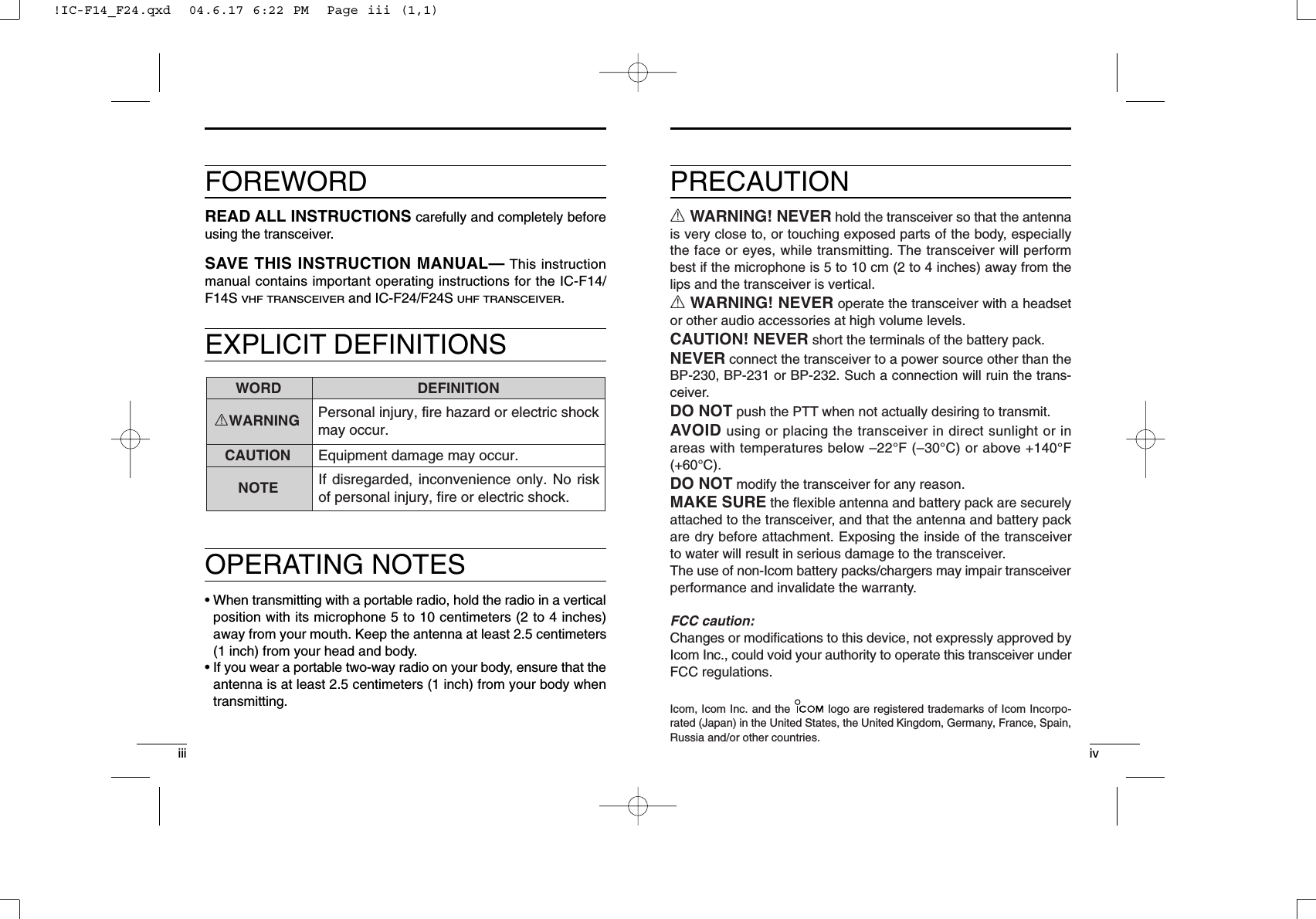
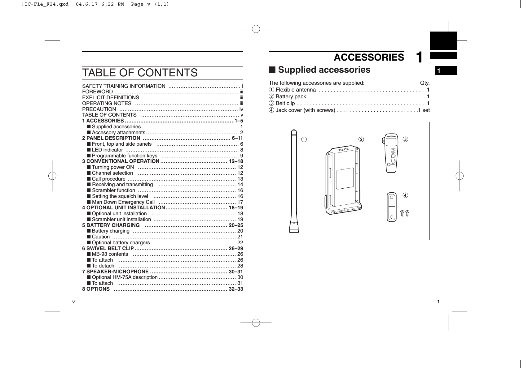
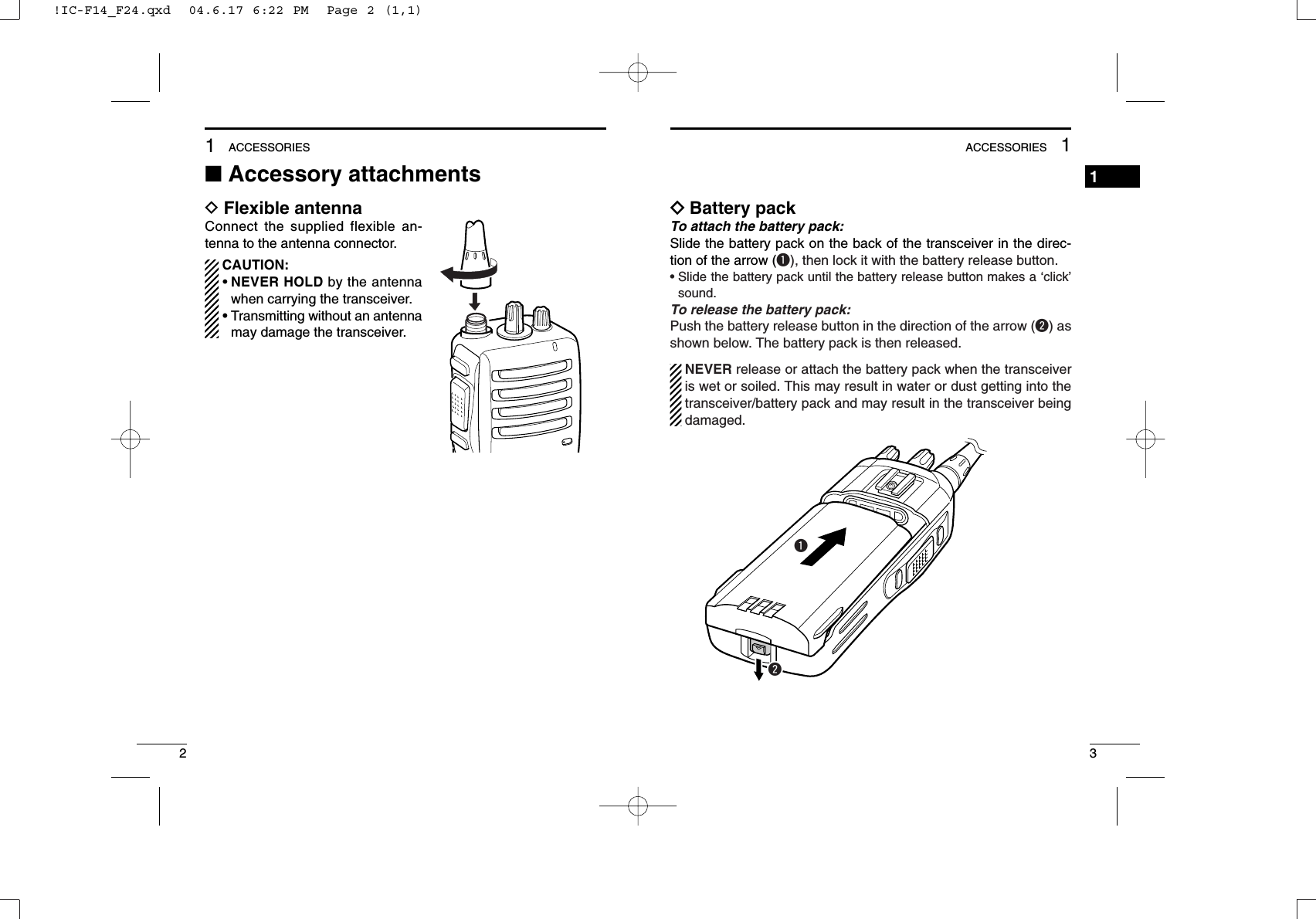
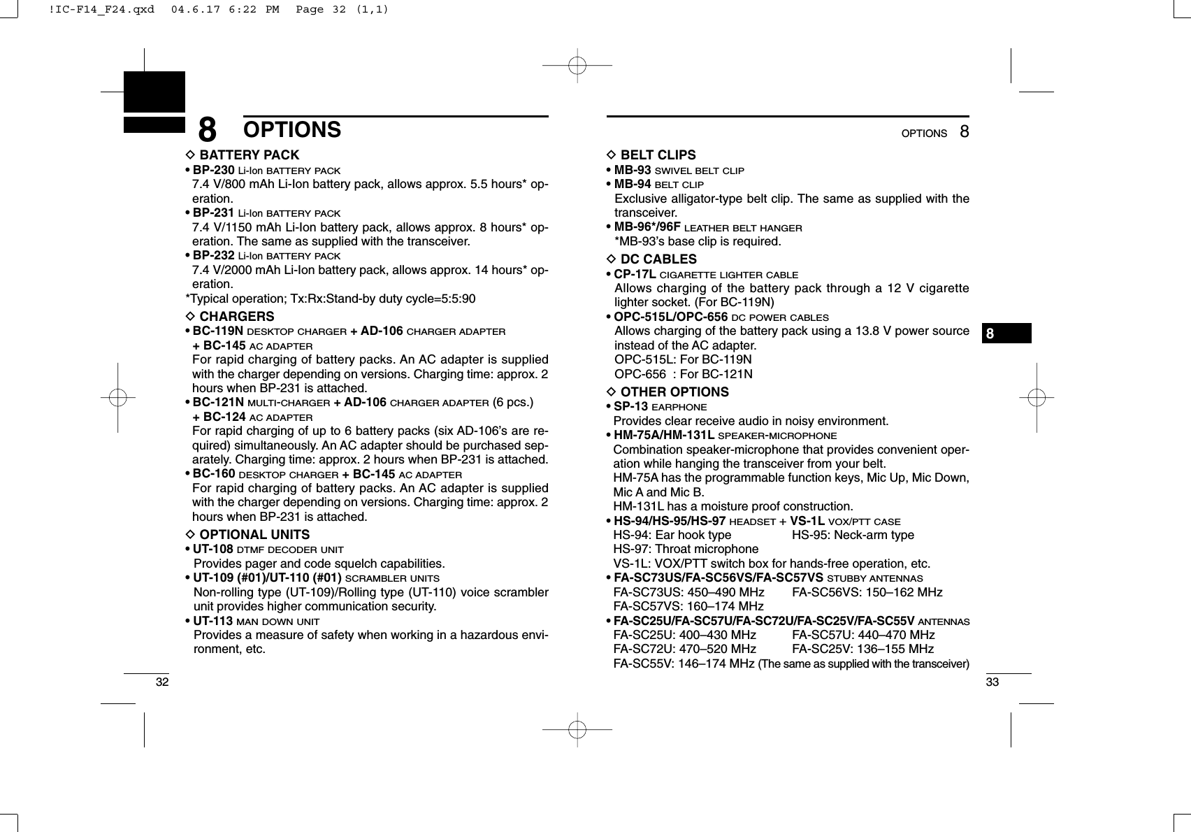
![41ACCESSORIES51ACCESSORIES1ïJack coverAttach the jack cover when the optional speaker-microphone is notused.wwqqqwTo attach the jack cover:qAttach the jack cover to the[SP MIC] connector.wTighten the screws.To detach the jack cover:qUnscrew the screws with aphillips screwdriver.wDetach the jack cover for thespeaker-microphone connec-tion.DBelt clipTo attach the belt clip:qRelease the battery pack if it is attached.wSlide the belt clip in the direction of the arrow until the belt clip islocked and makes a ‘click’ sound.To detach the belt clip:qRelease the battery pack if it is attached.wPinch the clip (q), and slide the belt clip in the direction of thearrow (w).qw!IC-F14_F24.qxd 04.6.17 6:22 PM Page 4 (1,1)](https://usermanual.wiki/ICOM-orporated/277602.Manual-rev/User-Guide-484236-Page-6.png)
![72PANEL DESCRIPTION262PANEL DESCRIPTION■Front, top and side panelsqCHANNEL SW/SELECTOR• IC-F14S/F24S: Toggle the channel switch to select the pre-pro-grammed channel 1 or 2.• IC-F14/F24 : Rotate the channel selector to select the pre-programmed memory channels.wVOLUME CONTROL [VOL]Rotate to turn the power ON/OFF and adjust the audio level.rqwyuieMicrophoneSpeakertIC-F14S/F24S IC-F14/F24eLED INDICATOR (p. 8)➥Lights red while transmitting.➥Lights green while receiving a signal, or when the squelch isopen.➥Lights/blinks orange when the matched 2/5-tone code is re-ceived, according to the pre-programming.rSPEAKER-MICROPHONE CONNECTOR [SP MIC]Connects the optional speaker-microphone. (p. 31)tDEALER-PROGRAMMABLE KEY [Lower]The desired function can be assigned by your dealer. (p. 9)yPTT SWITCH [PTT]Push and hold to transmit; release to receive.uDEALER-PROGRAMMABLE KEY [Upper]The desired function can be assigned by your dealer. (p. 9)iANTENNA CONNECTORConnects the supplied antenna.DDProgrammable key reference*These functions are available when the optional Speaker-Microphoneis connected. (p. 31)UpperMic Up*Mic A*LowerMic Down*Mic B*[SP MIC] jack coverNOTE: Attach the [SP MIC] jack cover when the optional speak-er-microphone is not used. (p. 4) !IC-F14_F24.qxd 04.6.17 6:22 PM Page 6 (1,1)](https://usermanual.wiki/ICOM-orporated/277602.Manual-rev/User-Guide-484236-Page-7.png)
![92PANEL DESCRIPTION282PANEL DESCRIPTION‘‘LED indicatorThe LED indicator indicates several informa-tion as follows;(Ref.; R=Red, G=Green, O=Orange) R R R R R R O O O O R R R R R R G G G R •TX: Turns Red while transmitting a signal.•RX: Turns Green while receiving a signal.•Call LED (ON): When receiving a matched 2/5-tone.•Call LED (Blink): When receiving a matched 2/5-tone.•Fast/Slow scan: Blinks while Fast/Slow scan is activated.•Low BATT1: You should charge the battery. (blinks slowly)•Low BATT2: You must charge the battery. (blinks fast)•TX low BATT1: Low BATT1 was detected during TX mode.•TX low BATT2: Low BATT2 was detected during TX mode.■Programmable function keysThe following functions can be assigned to [Upper], [Lower], [MicUp]*, [Mic Down]*, [Mic A]* and [Mic B]* programmable functionkeys.Consult your Icom dealer or system operator for details concerningyour transceivers programming.If the programmable function names are bracketed in the followingexplanations, the specific key used to activate the function dependson programming.*These keys are available when the optional Speaker-Microphone isconnected. (p. 31)SCAN A KEY➥This key’s operation depends on the Power ON Scan setting.When the power ON scan function is turned OFF;Push to start and cancel scanning operation. In case of trans-mission during scan, cancels scanning.When the power ON scan function is turned ON;Push to pause scanning. Scanning resumes after passing aspecified time period. In case of transmission during scan,pauses scanning. Scanning resumes after passing a specifiedtime period.SCAN B KEYPush to start and cancel scanning operation. In case of transmis-sion during scan, pauses scanning. Scanning resumes after pass-ing a specified time period. PRIORITY CHANNEL KEYS➥Push to select the Priority A or Priority B channel.➥Push and hold [Prio A (Rewrite)] to rewrite the Prio A channel.MR-CH 1/2/3/4 KEYSPush to select a memory channels 1 to 4 directly.NOTE: The memory channels 3 and 4 are available for IC-F14S/F24S when [MR-CH 3] and [MR-CH 4] keys are assigned.!IC-F14_F24.qxd 04.6.17 6:22 PM Page 8 (1,1)](https://usermanual.wiki/ICOM-orporated/277602.Manual-rev/User-Guide-484236-Page-8.png)
![102PANEL DESCRIPTION112PANEL DESCRIPTION2MONITOR KEY➥Mute and release the CTCSS (DTCS) or 2-tone squelch mute.Open any squelch/deactivate any mute while pushing this key.(LMR operation only)➥Activates one of (or two of) the following functions on each chan-nel independently: (PMR operation only)• Push and hold to un-mute the channel (audio is emitted; ‘Audible’condition).• Push to mute the channel (sets to ‘Inaudible’only).• Push to un-mute the channel (sets to ‘Audible’only).• Push after the communication is finished to send a ‘reset code’.NOTE: The un-mute condition (‘Audible’condition) may auto-matically return to the mute condition (‘Inaudible‘ condition)after a specified period.LOCK KEYPush and hold to electronically lock all programmable keys exceptthe following:[Call] (incl. Call A and Call B), [Moni(Audi)] and [Emergency] keys.OUTPUT POWER SELECTION KEYSelect the transmit output power temporarily or permanently, de-pending on the pre-setting.•Ask your dealer for the output power level for each selection.TALK AROUND KEYTurn the talk around function ON and OFF.•The talk around function equalizes the transmit frequency to the re-ceive frequency for transceiver-to-transceiver communication.WIDE/NARROW KEY➥Push to select the IF bandwidth to wide.➥Push and hold to select the IF bandwidth to narrow.• The wide passband width can be selected from 25.0 or 20.0 kHzusing the CS-F14 CLONING SOFTWARE. (PMR operation only) Askyour dealer for details.DTMF AUTODIAL KEYPush to transmit the programmed DTMF code.CALL KEYSPush to transmit a 2/5-tone code.•Call transmission is necessary before you call another station de-pending on your signalling system.•[Call A] and/or [Call B] keys may be available when your system em-ploys selective ‘Individual/Group’calls. Ask your dealer which call isassigned to each key.EMERGENCY KEYS➥Push and hold to transmit an emergency call.➥When [Emergency Single (Silent)] or [Emergency Repeat(Silent)] is pushed, an emergency call is transmitted without abeep emission.• If you want to cancel the emergency call, push (or push and hold)the key again before transmitting the call.• The emergency call is transmitted one time only or repeatedly untilreceiving a control code depending on the pre-setting.VOICE SCRAMBLER FUNCTION KEYS➥Push to turn the voice scrambler function OFF.➥Push and hold to turn the voice scrambler function ON.OPT OUT KEYS➥Push to inactivate the connected output signal level.➥Push and hold to activate the connected output signal level.SIREN KEYPush to emit a siren. This function can be used for situations otherthan an emergency alert such as a security alarm for example.!IC-F14_F24.qxd 04.6.17 6:22 PM Page 10 (1,1)](https://usermanual.wiki/ICOM-orporated/277602.Manual-rev/User-Guide-484236-Page-9.png)
![133CONVENTIONAL OPERATION3123CONVENTIONAL OPERATION■Turning power ON➥Rotate [VOL] to turn power ON.■Channel selectionIC-F14S/F24S:Toggle [CHANNEL SWITCH] to selectthe channel 1 or 2, or, push one of [MR-CH 1] to [MR-CH 4] key to select a chan-nel directly.• The memory channels 3 and 4 are avail-able when [MR-CH 3] and [MR-CH 4]keys are assigned.IC-F14/F24:Rotate [CHANNEL SELECTOR] to se-lect the desired operating channel, in se-quence; or, push one of [MR-CH 1] to[MR-CH 4] key to select a channel di-rectly.AUTOMATIC SCAN TYPE:Channel setting is not necessary for this type. When turning thepower ON, the transceiver automatically starts scanning. Scanningstops when receiving a call.[VOL][CHANNEL SELECTOR][CHANNEL SWITCH]■Call procedureWhen your system employs tone signalling (excluding CTCSS andDTCS), the call procedure may be necessary prior to voice trans-mission. The tone signalling employed may be a selective callingsystem which allows you to call specific station(s) only and preventunwanted stations from contacting you.qSelect the desired TX code channel or 2/5-tone code accordingto your System Operator’s instructions.• This may not be necessary depending on programming.wPush the call key (assigned to one of the dealer programmablekeys). (p. 9)eAfter transmitting a 2/5-tone code, the remainder of your com-munication can be carried out in the normal fashion.Selective calling Non-selective calling!IC-F14_F24.qxd 04.6.17 6:22 PM Page 12 (1,1)](https://usermanual.wiki/ICOM-orporated/277602.Manual-rev/User-Guide-484236-Page-10.png)
![153CONVENTIONAL OPERATION3143CONVENTIONAL OPERATION■Receiving and transmittingNOTE: Transmitting without an antenna may damage the trans-ceiver. See p. 2 for antenna attachment.Receiving:qRotate [VOL] to turn power ON.wToggle [CHANNEL SWITCH] (IC-F14S/F24S), rotate [CHAN-NEL SELECTOR] (IC-F14/F24) or push one of [MR-CH 1] to[MR-CH 4] key to select a channel.For IC-F14S/F24S:The memory channels 3 and 4 are available when [MR-CH 3]and [MR-CH 4] keys are assigned.eWhen receiving a call, adjust the audio output level to a comfort-able listening level.Transmitting:Wait for the channel to become clear to avoid interference.qWhile pushing and holding [PTT], speak into the microphone ata normal voice level.• When a tone signalling system is used, the call procedure de-scribed on p. 13 may be necessary.wRelease [PTT] to return to receive.IMPORTANT!: To maximize the readability of your signal;1. Pause briefly after pushing [PTT].2. Hold the microphone 5 to 10 cm (2 to 4 inches) from yourmouth, then speak into the microphone at a normal voicelevel.DTransmitting notes• Transmit inhibit functionThe transceiver has several inhibit functions which restrict trans-mission under the following conditions:- The channel is in mute condition.- Channel is busy.- Un-matched (or matched) CTCSS is received.- The selected channel is a ‘receive only’channel.• Time-out timerAfter continuous transmission for the pre-programmed time period, thetime-out timer activates, and causes the transceiver to stop transmit-ting.• Penalty timerOnce the time-out timer activates, transmission is further inhibitedfor a period determined by the penalty timer.DDTMF transmissionIf the transceiver has [DTMF Autodial] assigned to it, the automaticDTMF transmission function is available.➥Push [DTMF Autodial] to transmit the DTMF code.!IC-F14_F24.qxd 04.6.17 6:22 PM Page 14 (1,1)](https://usermanual.wiki/ICOM-orporated/277602.Manual-rev/User-Guide-484236-Page-11.png)
![173CONVENTIONAL OPERATION3163CONVENTIONAL OPERATION■Scrambler functionThe optional voice scrambler units UT-109 (#01) and UT-110 (#01)provide high performance private communication between stationswith the same scrambler codes.➥Push and hold [Scrambler] to turn the scrambler function ON.➥Push [Scrambler] to turn the scrambler function OFF.■Setting the squelch levelThe squelch circuit mutes the received audio signal depending onthe signal strength.qWhile pushing [PTT] and [Lower],rotate [VOL] to turn the power ONto enter the squelch level adjust-ment mode.wPush [Upper] to increase thesquelch level (tight squelch) or[Lower] to decrease the squelchlevel (loose squelch).eRotate [VOL] to turn the powerOFF to fix the squelch level.[VOL][Upper][Lower][PTT]■Man Down Emergency CallThe man down emergency call function transmits an emergencycall automatically, after the transceiver laying down in a horizontalposition for a pre-set time period. (The optional UT-113 MAN DOWNUNITis required.)After the emergency call, the transceiver performs transmission andreception alternately with the following conditions:- Transmits the microphone signals.- Receives the signal and emits audio.When the emergency cancel code is received, the function is can-celled.IMPORTANT!: Set an emergency channel individually, to providecertain emergency call operation is recommended.!IC-F14_F24.qxd 04.6.17 6:22 PM Page 16 (1,1)](https://usermanual.wiki/ICOM-orporated/277602.Manual-rev/User-Guide-484236-Page-12.png)
![194OPTIONAL UNIT INSTALLATION4184OPTIONAL UNIT INSTALLATION■Optional unit installationInstall the optional unit as follows:qRotate [VOL] to turn the power OFF, and remove the batterypack. (p. 3)wRemove the unit cover.NOTE: Use a flat head screw driver or a similar flat instru-ment, and insert into the hollow of the chassis, then lift andtake away the unit cover. (The removed cover cannot be usedagain.)eInstall the unit as shown below.rReplace the unit cover and the battery pack, then rotate [VOL] toturn the power ON.NOTE: The optional UT-109/UT-110 SCRAMBLER UNITSrequiressome PC board modifications. Please refer to the additional in-stallation as at right.*This illustration is described with the UT-110.■Scrambler unit installationThe following PC board modification is required when installing theoptional UT-109 or UT-110.qRotate [VOL] to turn the power OFF, and remove the batterypack. (p. 3)wRemove the unit cover as shown at left (Optional unit installation.)eCut the pattern on the PCB at the TX mic circuit (MIC) and RXAF circuit (DISC) as shown below.rInstall the scrambler unit as shown at left (Optional unit installa-tion.)tReplace the unit cover and the battery pack, then rotate [VOL] toturn the power ON.NOTE: When uninstalling thescrambler unitBe sure to re-solder the discon-nected points at left, otherwise noTX modulation or AF output isavailable.!IC-F14_F24.qxd 04.6.17 6:22 PM Page 18 (1,1)](https://usermanual.wiki/ICOM-orporated/277602.Manual-rev/User-Guide-484236-Page-13.png)
![317SPEAKER-MICROPHONE7307SPEAKER-MICROPHONE■Optional HM-75A descriptionABOFF ONLOCKEarphone jackPTT switchLock switch:Locks all keys except [PTT].[Mic A]/[Mic B] keys*[Mic Up]/[Mic Down] keys**The desired function can be assigned independently by your dealer. (p. 9)Rear■To attachAttach the connector of the speaker-microphone into the [SP MIC]connector on the transceiver and tighten the screw.CAUTION: When connecting the speaker-microphone to thetransceiver, make sure that power to the transceiver is turnedOFF, otherwise the CPU may malfunction.IMPORTANT!: KEEP the [SP MIC] jack cover attached (trans-ceiver) when the speaker-microphone is not in use (p. 4). Waterwill not get into the transceiver even if the cover is not attached,however, the terminals (pins) will become rusty, or the trans-ceiver will function abnormally if the connector becomes wet.To [SP MIC] connectorCAUTION: Attach the speaker-microphone s connector securely to prevent accidental dropping, or water intrusion in the connector.!IC-F14_F24.qxd 04.6.17 6:22 PM Page 30 (1,1)](https://usermanual.wiki/ICOM-orporated/277602.Manual-rev/User-Guide-484236-Page-19.png)