ICOM orporated 278100 VHF Mobile Transceiver User Manual IC F1721D
ICOM Incorporated VHF Mobile Transceiver IC F1721D
UserManual.wiki
>
ICOM orporated
>
278100 User Manual
Manual
Navigation menu
Upload a User Manual
Namespaces
Wiki Guide
HTML
PDF
Info
Views
User Manual
Discussion / Help
Navigation
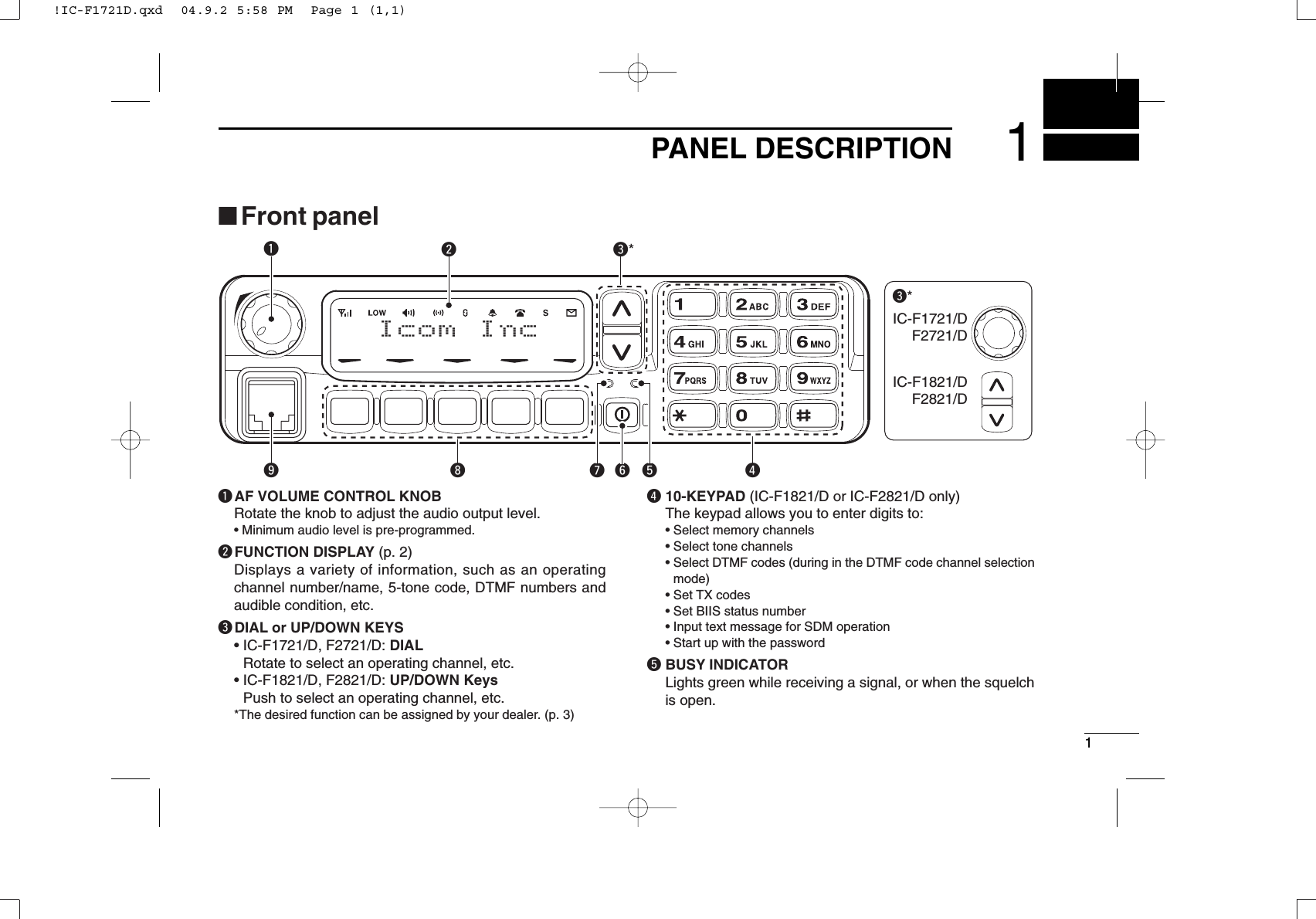
![21PANEL DESCRIPTIONyPOWER SWITCH [POWER]Push to turn the power ON and OFF.• The following functions are available at power ON as options:- Automatic scan start- Password prompt- Set modeuTRANSMIT INDICATORLights red while transmitting.iDEALER-PROGRAMMABLE KEYSDesired functions can be programmed independently byyour dealer. (p. 3)In this instruction manual, these keys are from the left,called [P0]/[P1]/[P2]/[P3]/[P4].oMICROPHONE CONNECTORConnect the supplied microphone or optional DTMF micro-phone.NEVER connect non-specified microphones. The pinassignments may be different and the transceiver maybe damaged.DDMICROPHONEThe supplied microphone has a PTT switch and a hangerhook.• The following functions are available when the microphone is on oroff hook:- Automatic scan start when on hook.- Automatic priority channel selection when off hook.- Sets to ‘Inaudible’condition (mute condition) when on hook.- Sets to ‘Audible’condition (unmute condition) when off hook.■Function displayqSIGNAL STRENGTH INDICATORIndicates relative signal strength level.wLOW POWER INDICATORAppears when low output power is selected.• When the battery power decreases to a specified level, lowpower is selected automatically.eAUDIBLE INDICATOR➥Appears when the channel is in the ‘audible’(unmute)condition.➥Appears when the specified 2/5-tone/BIIS code isreceived.rCOMPANDER INDICATORAppears when the compander function is activated.tSCRAMBLER INDICATORAppears when the voice scrambler function is activated.136.1 Nar q w e r t y uio!1!0!IC-F1721D.qxd 04.9.2 5:58 PM Page 2 (1,1)](https://usermanual.wiki/ICOM-orporated/278100/User-Guide-484564-Page-6.png)
![31PANEL DESCRIPTIONyBELL INDICATORAppears/blinks when the specific 2/5-tone/BIIS code isreceived, according to the pre-programming.uCALL CODE MEMORY INDICATORAppears when the call code memory is selected.iSCROLL INDICATORAppears when a received SDM including more than 12characters is displayed.oSDM INDICATORAppears when an SDM is received, or a transmit SDM isselected.!0 ALPHANUMERIC DISPLAYDisplays an operating channel number, channel name, Setmode contents, DTMF code, etc. The indication type can be selected from 1 line or 2 lines.Ask your dealer for details.In this instruction manual, the LCD illustration is describedwith 2 lines.!1 ACTIVATED KEY INDICATORAppears above the key assigned as the [DIGITAL] keywhen that key has been activated.■Programmable function keysThe following functions can be assigned to [DIAL]*, [P0],[P1], [P2], [P3] and [P4] programmable function keys.Consult your Icom dealer or system operator for details con-cerning your transceivers programming.If the programmable function names are bracketed in the fol-lowing explanations, the specific key is used to activate thefunction depends on the programming.*The assignable functions are restricted to [DIAL].(✩marked functions are available.)✩CH UP AND DOWN KEYS ➥Push (or Rotate)* to select an operating channel.➥Push (or Rotate)* to select a transmit code channel afterpushing [TX Code CH Select].➥Push (or Rotate)* to select a DTMF channel after pushing[DTMF Autodial].➥Push (or Rotate)* to select a scan group after pushing andholding [Scan A Start/Stop]/[Scan B Start/Stop].➥Push (or Rotate)* to select a BIIS code, status number orSDM after pushing [Digital].*Rotate when this function is assigned to [DIAL].✩ZONE UP AND DOWN KEY (This function is for [DIAL] only)Rotate to select the desired zone.!IC-F1721D.qxd 04.9.2 5:58 PM Page 3 (1,1)](https://usermanual.wiki/ICOM-orporated/278100/User-Guide-484564-Page-7.png)
![41PANEL DESCRIPTIONZONE SELECT KEYPush this key, then push [CH Up] or [CH Down] to select thedesired zone.What is “zone”?The desired channels are assigned into a zone accordingto the intended use.SCAN A KEY➥This key’s operation depends on the Power ON Scan set-ting.When the power ON scan function is turned OFF;Push to start and cancel scanning operation. In case oftransmission during scan, cancels scanning.When the power ON scan function is turned ON;Push to pause scanning. Scanning resumes after passinga specified time period. In case of transmission duringscan, pauses scanning. Scanning resumes after passinga specified time period specified.➥Push and hold this key for 1 sec. to indicate the scangroup, then push [CH Up] or [CH Down] to select thedesired group.SCAN B KEY➥Push to start and cancel scanning operation. In case oftransmission during scan, pauses scanning. Scanningresumes after passing a specified time period. ➥Push and hold this key for 1 sec. to indicate the scangroup, then push [CH Up] or [CH Down] to select thedesired group.SCAN TAG KEYPush to add or delete the selected channel to the scan group.PRIORITY CHANNEL KEYS➥Push to select Priority A or Priority B channel.➥Push and hold [Prio A (Rewrite)] to rewrite the Prio A chan-nel.MR-CH 1/2/3/4 KEYSPush to select an operating channel directly.MONITOR KEY➥Mute and release the CTCSS (DTCS) or 2-tone squelchmute. Open any squelch/deactivate any mute while push-ing this key. (LMR operation only)➥Activates one of (or two of) the following functions on eachchannel independently: (PMR or BIIS PMR operation only)• Push and hold to un-mute the channel (audio is emitted;‘Audible’condition).• Push to mute the channel (sets to ‘Inaudible’only).• Push to un-mute the channel (sets to ‘Audible’only).• Push after the communication is finished to send a ‘resetcode’.NOTE: The un-mute condition (‘Audible’condition) mayautomatically return to the mute condition (‘Inaudible‘ con-dition) after a specified period.!IC-F1721D.qxd 04.9.2 5:58 PM Page 4 (1,1)](https://usermanual.wiki/ICOM-orporated/278100/User-Guide-484564-Page-8.png)
![51PANEL DESCRIPTIONPUBLIC ADDRESS KEYWhen an optional OPC-617 ACC CABLEis installed, the audiooutput via the cable can be controlled from the transceiverseparately from the [VOL] control.•This audio output can be used as a ‘public address’function whenan external audio amplifier and speaker are connected additionally.•Push this key, then speak into the microphone while pushing thePTT switch.•The [CH Up]/[CH Down] keys allow you to set the audio output levelfrom minimum to maximum.RX SPEAKER KEYWhen the external connections are made for the ‘publicaddress’function, the external speaker drive function is alsoavailable simultaneously. The received audio can be heardvia the external speaker when this key is pushed.•This function is useful when you are out of the vehicle.•The audio output level is linked to the transceiver’s volume control.LIGHT KEYPush to turn the transceiver’s backlight ON temporarily whenthe backlight function is turned OFF in user set mode.LOCK KEYPush and hold to electronically lock all programmable keysexcept the following:[Call] (incl. Call A and Call B), [Moni(Audi)] and [Emergency].OUTPUT POWER SELECTION KEYPush to select the transmit output power temporarily or per-manently, depending on the pre-setting.•Ask your dealer for the output power level for each selection.C.TONE CHANNEL ENTER KEYPush to select the continuous tone channel using [CH Up]/[CH Down] to change the tone frequency/code setting afterpushing this key for permanent operation.TALK AROUND KEYTurn the talk around function ON and OFF.•The talk around function equalizes the transmit frequency to thereceive frequency for transceiver-to-transceiver communication.WIDE/NARROW KEYPush to toggle the IF bandwidth between wide and narrow.• The wide passband width can be selected from 25.0 or 20.0 kHzusing the CS-F1700 CLONING SOFTWARE. (PMR or BIIS PMR opera-tion only) Ask your Dealer for details.DTMF AUTODIAL KEY➥Push to enter the DTMF channel selection mode. Thenselect the desired DTMF channel using [CH Up]/[CHDown]/[CH Up/Down] keys.➥After selecting the desired DTMF channel, push this key totransmit the DTMF code.DTMF RE-DIAL KEYPush to transmit the last-transmitted DTMF code.!IC-F1721D.qxd 04.9.2 5:58 PM Page 5 (1,1)](https://usermanual.wiki/ICOM-orporated/278100/User-Guide-484564-Page-9.png)
![61PANEL DESCRIPTIONCALL KEYSPush to transmit a 2/5-tone/BIIS ID code.•Call transmission is necessary before calling another stationdepending on your signalling system.•[Call A] and/or [Call B] may be available when your system employsselective ‘Individual/Group’calls. Ask your dealer which call isassigned to each key.EMERGENCY KEYS➥Push and hold to transmit an emergency call.➥When [Emergency Single (Silent)] or [Emergency Repeat(Silent)] is pushed, an emergency call is transmitted withouta beep emission and LCD indication change.• If you want to cancel the emergency call, push (or push andhold) the key again before transmitting the call.• The emergency call is transmitted one time only or repeatedlyuntil receiving a control code depending on the pre-setting.TX CODE ENTER KEY (PMR or BIIS PMR operation only)Push to enter the ID code edit mode directly, for both 5-toneand MSK. Then set the desired digit using [CH Up]/[CH Down]/[CH Up/Down] or 10-keypad*. (p. 11)*IC-F1821/D or IC-F2821/D onlyTX CODE CHANNEL SELECT KEY➥Push to enter the ID code channel selection mode directly.Then set the desired channel using [CH Up]/[CH Down]/[CH Up/Down]. (p. 10)➥While in ID code channel selection mode, push for 1 sec. toenter the ID code edit mode for 5-tone and MSK. Then setthe desired digit using [CH Up]/[CH Down]/[CH Up/Down]or 10-keypad*. (p. 11)*IC-F1821/D or IC-F2821/D only✩TX CODE CHANNEL UP/DOWN KEYSPush (or Rotate)* to select a TX code channel directly.*Rotate when this function is assigned to [DIAL].ID MEMORY READ KEY (PMR or BIIS PMR operation only)➥Recalls detected ID codes.•Push this key, then push [CH Up]/[CH Down] for selection.•Up to 5 ID’s are memorized.➥Push and hold to erase the selected memorized ID’s.VOICE SCRAMBLER FUNCTIONPush to toggle the voice scrambler function ON and OFF.COMPANDER KEYPush to toggle the compander function ON and OFF. The compander function reduces noise components from thetransmitting audio to provide clear communication.!IC-F1721D.qxd 04.9.2 5:58 PM Page 6 (1,1)](https://usermanual.wiki/ICOM-orporated/278100/User-Guide-484564-Page-10.png)
![71PANEL DESCRIPTIONUSER SET MODE KEY➥Push and hold to enter user set mode.• During user set mode, push this key to select an item, and push[CH Up]/[CH Down] to change the value or condition.➥Push and hold this key again to exit user set mode.User set mode is also available via the ‘Power ON function.’Please refer to p. 13 also.OPT OUT KEYSPush to control the optional unit connector output signal level.DIGITAL KEY (BIIS operation only)➥Push to select the call ID list, transmit message and stand-by condition. Toggles between queue channel andreceived message record indication after queue channel isselected.➥Push and hold to select queue channel indication.✩STATUS UP/DOWN KEYS (BIIS operation only)➥While in the standby condition, push (or rotate)* to displaythe transmit status indication and select a status number.➥When a received SDM is displayed, push (or rotate)* tocancel the automatic scroll and scroll the message manu-ally.➥When an SDM that contains more than 12 characters isdisplayed, push (or rotate)* to scroll the message manually.*Rotate when this function is assigned to [DIAL].DFor Digital mode operation onlyINDIVIDUAL KEY➥Push to enter the individual ID code selection mode direct-ly. Then select the desired individual ID code using [CHUp]/[CH Down]/[CH Up/Down]. (p. 12)➥Push to stop the beep emission when receiving a matchedindividual ID code.TALKGROUP KEY➥Push to enter the talkgroup ID code selection mode direct-ly. Then select the desired talkgroup ID code using [CHUp]/ [CH Down]/[CH Up/Down]. (p. 12)➥Push to stop the beep emission when receiving a matchedtalkgroup ID code.!IC-F1721D.qxd 04.9.2 5:58 PM Page 7 (1,1)](https://usermanual.wiki/ICOM-orporated/278100/User-Guide-484564-Page-11.png)
![82BASIC OPERATION■Turning power ONqPush [ ] to turn the power ON.wIf the transceiver is programmed for a start up password,input the digit codes as directed by your dealer.• 10-keypad* can be used for password input.*IC-F1821/D or IC-F2821/D only:• The keys as below can be used for password input:• The transceiver detects numbers in the same block as identical.Therefore “01234” and “56789” are the same.eWhen the “PASSWORD” indication does not clear afterinputting 4 digits, the input code number may be incorrect.Turn the power off and start over in this case.■Channel selectionSeveral types of channel selections are available. Methodsmay differ according to your system set up.NON-ZONE TYPE:Push [CH Up] or [CH Down], or rotate [CH Up/Down] to selectthe desired operating channel, in sequence; or, push one of[MR-CH 1] to [MR-CH 4] keys to select a channel directly.ZONE TYPE:Push [Zone] then push [CH Up] or [CH Down], or rotate [ZoneUp/Down] to select the desired zone.AUTOMATIC SCAN TYPE:Channel setting is not necessary for this type. When turningpower ON, the transceiver automatically starts scanning.Scanning stops when receiving a call.KEYNUMBER 0549382716P0 P4P3P2P1P0 P4P3P2P1*In this instruction manual, these keys are from the left, called [P0]/[P1]/[P2]/[P3]/[P4].!IC-F1721D.qxd 04.9.2 5:58 PM Page 8 (1,1)](https://usermanual.wiki/ICOM-orporated/278100/User-Guide-484564-Page-12.png)
![92BASIC OPERATION■Call procedureWhen your system employs tone signaling (excluding CTCSSand DTCS), the call procedure may be necessary prior to voicetransmission. The tone signalling employed may be a selec-tive calling system which allows you to call specific station(s)only and prevent unwanted stations from contacting you.qSelect the desired TX code channel, 2/5-tone code,Individual ID code* or Talkgroup ID code* according toyour System Operator’s instructions.• This may not be necessary depending on programming.• Refer to pgs. 10–12 for selection.*Digital mode operation only.wPush the call key (assigned to one of the dealer program-mable keys) or [PTT].eAfter transmitting, the remainder of your communicationcan be carried out in the normal fashion.■Receiving and transmittingReceiving:qPush [ ] to turn the power ON.wPush [CH Up] or [CH Down], or rotate [CH Up/Down] toselect a channel, in sequence.eWhen receiving a call, adjust the audio output level to acomfortable listening level.Transmitting:Wait for the channel to become clear to avoid interference.qTake the microphone off hook.• 2-tone, 5-tone mute may be released. (The ‘audible’condition isselected and BUSY indicator lights green.)• A priority channel may be selected automatically.wWait for the channel to become clear.• The channel is busy when BUSY indicator lights green.ePush [CALL] when initiating a call from your side.• Coded audio may be heard from the transceiver, then “”appears.• This operation may not be necessary depending on your signal-ing system. Ask your dealer for details.rWhile pushing and holding [PTT], speak into the micro-phone at your normal voice level.tRelease [PTT] to receive.IMPORTANT: To maximize the readability of your signal;1. Pause briefly after pushing [PTT].2. Hold the microphone 5 to 10 cm (2 to 4 inches) fromyour mouth, then speak into the microphone at a normalvoice level.Selective calling Non-selective calling!IC-F1721D.qxd 04.9.2 5:58 PM Page 9 (1,1)](https://usermanual.wiki/ICOM-orporated/278100/User-Guide-484564-Page-13.png)
![102BASIC OPERATIONDTransmitting notes• Transmit inhibit functionThe transceiver has several inhibit functions which restricttransmission under the following conditions:- The channel is in mute condition (‘Inaudible’condition; “”does not appear.)- The channel is busy.- Un-matched (or matched) CTCSS is received.- The selected channel is a ‘receive only’channel.• Time-out timerAfter continuous transmission for the pre-programmed timeperiod, the time-out timer is activated, causing the transceiv-er to stop transmitting.• Penalty timerOnce the time-out timer is activated, transmission is furtherinhibited for a period determined by the penalty timer.DTX code channel selectionIf the transceiver has [TX Code CH Select] assigned to it, theindication can be toggled between the operating channelnumber (or name) and TX code channel number (or name).When the TX code channel number (or name) is displayed,[CH Up], [CH Down] or [CH Up/Down] selects the TX codechannel.USING [TX CODE CH SELECT] KEY:qPush [TX Code CH Select]— a TX code channel number(or name) appears.wPush [CH Up] or [CH Down], or rotate [CH Up/Down] toselect the desired TX code channel.ePush [Call] (or [PTT] during MSK operation) to transmit theselected TX code.USING [TX CODE CH UP]/[TX CODE CH DOWN] KEY:If the transceiver has a [TX Code CH Up], [TX Code CHDown] or [TX Code CH Up/Down] key assignment, the pro-grammed TX code channel can be selected directly whenpushed or rotated.NOTE for PMR or BIIS PMR operation:• The LCD indication is not changed when the operating channelnumber (or name) is displayed.• To check the selected TX code, push [TX Code CH Select].!IC-F1721D.qxd 04.9.2 5:58 PM Page 10 (1,1)](https://usermanual.wiki/ICOM-orporated/278100/User-Guide-484564-Page-14.png)
![112BASIC OPERATIONDTX code number edit(PMR or BIIS PMR operation only)If the transceiver has [TX Code CH Select] or [TX CodeEnter] assigned to it, TX code contents can be edited withinthe allowable digits.USING [TX CODE CH SELECT] KEY:qPush [TX Code CH Select] to enter the TX code channelselection mode.• Select the desired channel before entering the TX code channelselection mode if necessary.wPush [TX Code CH Select] for 1 sec. to enter the TX codeedit mode.ePush [TX Code CH Select] to select the desired digit to beedited.• The editable digit blinks.rPush [CH Up], [CH Down] or 10-keypad*, or rotate [CHUp/Down] to set the desired digit.tPush [TX Code CH Select] to set the digit. The editabledigit will move to the right automatically.• When the 10-keypad* is used to set, the editable digit will moveto the right automatically without pushing [TX Code CH Select].yRepeat rand tto input all allowable digits.uPush [Call] or [PTT] to transmit the edited TX code.*IC-F1821/D or IC-F2821/D onlyUSING [TX CODE ENTER] KEY:qSelect the desired TX code channel via [TX Code CHSelect]+[CH Up] or [CH Down], [TX Code CH Up], [TXCode CH Down] or [TX Code CH Up/Down].wPush [TX Code Enter] to enter the TX code edit mode.ePush [TX Code Enter] to select the desired digit to be edit-ed.• The editable digit blinks.rPush [CH Up], [CH Down] or 10-keypad*, or rotate [CHUp/Down] to set the desired digit .tPush [TX Code Enter] to set the digit. The editable digit willmove to the right automatically.• When the 10-keypad* is used to set, the editable digit will moveto the right automatically without pushing [TX Code CH Select].yRepeat rand tto input all allowable digits.uPush [Call] or [PTT] to transmit the edited TX code.*IC-F1821/D or IC-F2821/D only!IC-F1721D.qxd 04.9.2 5:58 PM Page 11 (1,1)](https://usermanual.wiki/ICOM-orporated/278100/User-Guide-484564-Page-15.png)
![122BASIC OPERATIONDIndividual ID code selection(Digital mode operation only)If the transceiver has [Individual] assigned to it, the indicationcan be toggled between the operating channel number (orname) and Individual ID code (or name). When the IndividualID code (or name) is displayed, [CH Up], [CH Down] or [CHUp/Down] selects the desired Individual ID code.qPush [Individual]— an Individual ID code (or name)appears.wPush [CH Up] or [CH Down], or rotate [CH Up/Down] toselect the desired Individual ID code.ePush [PTT] to transmit the selected Individual ID code.DTalkgroup ID code selection(Digital mode operation only)If the transceiver has [Talkgroup] assigned to it, the indicationcan be toggled between the operating channel number (orname) and Talkgroup ID code (or name). When the TalkgroupID code (or name) is displayed, [CH Up], [CH Down] or [CHUp/Down] selects the desired Talkgroup ID code.qPush [Talkgroup]— a Talkgroup ID code (or name)appears.wPush [CH Up] or [CH Down], or rotate [CH Up/Down] toselect the desired Talkgroup ID code.ePush [PTT] to transmit the selected Talkgroup ID code.DDTMF transmissionIf the transceiver has [DTMF Autodial] assigned to it, the auto-matic DTMF transmission function is available. Up to 8 DTMFchannels are available.TO SELECT A TX CODE:qPush [DTMF Autodial]— a DTMF channel appears.wPush [CH Up] or [CH Down], or rotate [CH Up/Down] toselect the desired DTMF channel.ePush [DTMF Autodial] to transmit the DTMF code in theselected DTMF channel.!IC-F1721D.qxd 04.9.2 5:58 PM Page 12 (1,1)](https://usermanual.wiki/ICOM-orporated/278100/User-Guide-484564-Page-16.png)
![132BASIC OPERATION■User set modeUser set mode is accessed with [User Set Mode] and allowsyou to set seldom-changed settings. In this case you can“customize” the transceiver operation to suit your preferencesand operating style.Entering the user set mode:qWhile pushing and holding [P1] and [P2], push [ ] to turnthe power ON. Then, push and hold [P0] to enter user setmode, allowing you to set seldom-changed settings.wPush [P0] several times to select the appropriate item.Then, push [Up] or [Down] or rotate [DIAL] to set thedesired level/condition.• Available set mode functions are Backlight, LCD Contrast,Beep, Beep Level, SQL Level, AF Min Level, Mic Gain andHorn.ePush [ ] (or push and hold [P0]) again to exit set mode.User set mode is also available via a programmable key.Please refer to p. 7 [User Set Mode] section.■Scrambler functionThe voice scrambler function provides private communicationbetween stations. The frequency inversion type is equippedto all versions, moreover, the optional Rolling or Non-rollingtype can be available.qPush [Scrambler] to turn the scrambler function ON.• “” appears.wPush [Scrambler] again to turn the scrambler functionOFF.• “” disappears.[P1] [ ][P0] [Up]/[Down] or [DIAL][P1] [P2] [ ]!IC-F1721D.qxd 04.9.2 5:58 PM Page 13 (1,1)](https://usermanual.wiki/ICOM-orporated/278100/User-Guide-484564-Page-17.png)
![143BIIS OPERATION■Default settingThe following functions are assigned to each programmablekey as the default. However, the assigned function can bechanged by your dealer. Ask your dealer for details.NOTE: [TX Code Enter] must be assigned to any key.[P0]; Call : Push to transmit a 5-tone/BIIS callwhen the selected channel is a 5-tone or MSK channel, respectively.[P1]; Digital : Push to select the call list ID/transmitmessage, or to display the receivemessage record for selection.[P3]; TX Code Enter : Push to enter the ID code edit modedirectly for both 5-tone and MSK.[P4]; Moni(Audi) : Push this key after the communica-tion to send a ‘Clear down’signalduring MSK channel operation.[P2]; Null : No function is assigned.[Up]/[Down]/[DIAL]; CH Up/Down: While in the standby condition,selects the operating channel.After pushing [Digital] or [TX CodeCH Select], selects call list or TXcode channel, respectively.■Receiving a callDDIndividual callqWhen an individual call is received;•Beeps sound.•“ ” appears and the mute is released.•The programmed text message (e.g.“CALLING”) and the callingstation ID (or text) is displayed when the display type is 2lines.•The programmed text message (e.g.“CALLING”) and the callingstation ID (or text) is displayed alternately when the display typeis 1line, depending on the setting.•“ ” appears or blinks depending on the setting.wPush and hold [PTT], then speak into the microphone at anormal voice level.•TX indicator lights red.eRelease [PTT] to return to receive.•BUSY indicator lights green while receiving a signal.rTo finish the conversation, push [P4] (Moni(Audi)) to sendthe ‘Clear down’signal. •Either station can send a ‘Clear down’signal.•“CLR DOWN” is displayed for 2 sec. (approx.).•“ ” disappears and the transceiver returns to the standby con-dition.Appears or blinksAppears0 500CALLINGP0 P4P3P2P1In this instruction manual, these keys are from the left, called [P0]/[P1]/ [P2]/[P3]/[P4].!IC-F1721D.qxd 04.9.2 5:58 PM Page 14 (1,1)](https://usermanual.wiki/ICOM-orporated/278100/User-Guide-484564-Page-18.png)
![153BIIS OPERATIONDDGroup callqWhen a group call is received;•Beeps sound.•“ ” appears and the mute is released.•The programmed text message (e.g.“GROUP”) and the callingstation ID (or text) is displayed when the display type is 2lines.•The programmed text message (e.g.“GROUP”) and the callingstation ID (or text) is displayed alternately when the display typeis 1line, depending on the setting.•“ ” appears or blinks depending on the setting.wPush and hold [PTT], then speak into the microphone at anormal voice level.NOTE: Only one station is permitted to speak.•TX indicator lights red.eRelease [PTT] to return to receive.•BUSY indicator lights green while receiving a signal.rTo finish the conversation, push [MONITOR] (Moni(Audi))to send the ‘Clear down’signal.•Either station can send a ‘Clear down’signal.•“CLR DOWN” is displayed for 2 sec. (approx.)•“ ” disappears and the transceiver returns to the standby con-dition.DDDisplaying the received call record— Queue indicationThe transceiver memorizes the calling station IDs for record.Up to 3 calls can be memorized, and the oldest call record iserased when a 4th call is received. However, once the trans-ceiver is powered OFF, the all records are cleared.qPush [P1] (Digital) for 1 sec.•Displays following indication.When a record is availableWhen no record is availablewPush [Up] or [Down], or rotate [DIAL] to select the desiredcall.ePush [P1] (Digital) for 1 sec. again to return to the standbycondition.•When no operation is performed for 30 sec., the transceiverreturns to the standby condition automatically.<QUEUE>NO QUEUE<QUEUE>-QUEUE!-Appears or blinksAppears1120GROUP!IC-F1721D.qxd 04.9.2 5:58 PM Page 15 (1,1)](https://usermanual.wiki/ICOM-orporated/278100/User-Guide-484564-Page-19.png)
![163BIIS OPERATION■Transmitting a callTotal of a 3 ways for code selection are available—selectingthe call code from memory, entering the call code from thekeypad and calling back from the queue channel record.DDUsing call memoryqWhile in the standby condition, push [P1] (Digital) to enterthe call code memory channel selection mode.•“ ” appears.wPush [Up] or [Down], or rotate [DIAL] to select the desiredcall code.ePush [P0] (Call) or [PTT]* to call.*PTT call can be made only when PTT call capability is permitted.NOTE: When no answer back is received, the trans-ceiver repeats the call 3 times (default) automatically,and “WAIT”is displayed during each call. However, anerror beep sounds and “FAILED”is displayed when noanswer back is received after the calls.rPush [PTT] to transmit; release to receive.tPush [P4] (Moni(Audi)) to send the ‘Clear down’signal.DDCalling back from the queue channelqWhile in the standby condition, push [P1] (Digital) for1 sec. to enter the queue memory channel selection mode.wPush [Up] or [Down] or rotate [DIAL] to select the desiredrecord.ePush [P0] (Call) or [PTT]* to call.*PTT call can be made only when PTT call capability is permitted.NOTE: When no answer back is received, the trans-ceiver repeats the call 3 times (default) automatically,and “WAIT”is displayed during each call. However, anerror beep sounds and “FAILED”is displayed when noanswer back is received after the calls.rPush [PTT] to transmit; release to receive.tPush [P4] (Moni(Audi)) to send the ‘Clear down’signal.<QUEUE>-QUEUE!-FLEET 100Call code text is displayed.Appears!IC-F1721D.qxd 04.9.2 5:58 PM Page 16 (1,1)](https://usermanual.wiki/ICOM-orporated/278100/User-Guide-484564-Page-20.png)
![173BIIS OPERATIONDDDirect code entryqWhile in the standby condition, push [P3] (TX Code Enter)to enter the TX code edit mode.•Editable code digit blinks.wPush [P3] (TX Code Enter) to select the desired digit to beedited.•Editable digit differs according to the setting.eSet the desired digit using [CH Up]/[CH Down]/[DIAL] or10-keypad*.*IC-F1821/D or IC-F2821/D onlyrPush [P3] (TX Code Enter) to set the digit, then theeditable digit will move to the right automatically.• When the 10-keypad is used to set, the editable digit will move tothe right automatically without pushing [P3] (TX Code Enter).tRepeat eand rto input all allowable digits.yPush [P0] (Call) or [PTT]* to call.*PTT call can be made only when PTT call capability is permitted.NOTE: When no answer back is received, the trans-ceiver repeats the call 3 times (default) automatically,and “WAIT”is displayed during each call. However, anerror beep sounds and “FAILED”is displayed when noanswer back is received after the calls.uPush [PTT] to transmit; release to receive.iPush [P4] (Moni(Audi)) to send the ‘Clear down’signal.For your informationWhen the “UpDate” setting for the call code is enabled, theset code is overwritten into the call code memory.0500!IC-F1721D.qxd 04.9.2 5:58 PM Page 17 (1,1)](https://usermanual.wiki/ICOM-orporated/278100/User-Guide-484564-Page-21.png)
![183BIIS OPERATION■Receiving a messageDDReceiving a status messageqWhen a status message is received;• Beeps sound.• The calling station ID (or text) and the status message is dis-played alternately, depending on the setting.wPush [P4] (Moni(Audi)) to return to the standby condition.NOTE: Only the calling station ID (or text) is displayed (nomessage is displayed alternately) when the scroll timer isset to ‘OFF.’In this case, push [Status Up]/[Status Down]to display the status message manually.DDReceiving an SDM (Short Data Message)qWhen an SDM is received;• Beeps sound.• The calling station ID (or text) and the SDM is displayed alter-nately, depending on the setting.• “” appearswWhen the received SDM includes more than 12 charac-ters, “” appears and the message scrolls automatically,when the automatic scroll function is activated.• Push [Status Up]/[Status Down] to scroll the message manually.ePush [P4] (Moni(Audi)) to return to the standby condition.SDM 8BASEBAS EBASEAppearsTX Status 01BASEBAS EBASE!IC-F1721D.qxd 04.9.2 5:58 PM Page 18 (1,1)](https://usermanual.wiki/ICOM-orporated/278100/User-Guide-484564-Page-22.png)
![193BIIS OPERATIONDDReceived message selectionThe transceiver memorizes the received messages forrecord. Up to 6 messages for status and SDM, or 95 charac-ter SDM’s can be memorized. The oldest message is erasedwhen the 7th message is received. However, once the trans-ceiver is powered OFF, all messages are cleared.qPush [P1] (Digital) for 1 sec.•Displays queue memory.wPush [P1] (Digital) momentarily.•Displays message memory.When a message is availableWhen no message is availableePush [Up] or [Down], or rotate [DIAL] to select the desiredmessage.•When selecting the SDM that includes more than 12 characters,“” appears and the message scrolls automatically, when theautomatic scroll function is activated.• Push [Status Up]/[Status Down] to scroll the message manually.rPush [P1] (Digital) for 1 sec. again to return to the standbycondition.•When no operation is performed for 30 sec., the transceiverreturns to the standby condition automatically.MESSAGE-NO MSG-MESSAGE-MSG!-!IC-F1721D.qxd 04.9.2 5:58 PM Page 19 (1,1)](https://usermanual.wiki/ICOM-orporated/278100/User-Guide-484564-Page-23.png)
![203BIIS OPERATION■Transmitting a statusDDGeneralThe status message can be selected with the programmedtext, and the message text is also displayed on the functiondisplay of the called station.Up to 24 status types (1 to 24) are available, and the statusmessages 22 and 24 have designated meanings.Status 22: Emergency*Status 24: GPS request*The status 22 can also be used as a normal status message bydisabling the designated meaning. However, the status 24 is fixed.The status call can be sent with both individual and groupcalls.DDTransmitting a statusqWhile in the standby condition, push [P1] (Digital), thenpush [Up] or [Down], or rotate [DIAL] to select the desiredstation/group code.wPush [P1] (Digital) again, then push [UP] or [DOWN] toselect the desired status message.Or, you can select the desired status message using[Status Up]/[Status Down] key directly.ePush [P0] (Call) or [PTT]* to transmit the status messageto the selected station/group.*PTT call can be made only when PTT call capability is permitted.•2 beeps will sound and the transceiver returns to the standbycondition automatically when the transmission is successful.TX Status 01Status message is displayed.!IC-F1721D.qxd 04.9.2 5:58 PM Page 20 (1,1)](https://usermanual.wiki/ICOM-orporated/278100/User-Guide-484564-Page-24.png)
![213BIIS OPERATIONDDGeneralThe short data message, SDM, can be sent to an individualstation or group stations. Also, 8 SDM memory channels areavailable and the messages can be edited via PC program-ming.DDTransmitting an SDMqWhile in the standby condition, push [P1] (Digital), thenpush [Up] or [Down] or rotate [DIAL] to select the desiredstation/group code.wPush [P1] (Digital) again, then push [Up] or [Down] orrotate [DIAL] to select the desired SDM.Or, you can select the desired SDM using [Status Up]/[Status Down] key directly.ePush [P0] (Call) or [PTT]* to transmit the SDM to theselected station/group.*PTT call can be made only when PTT call capability is permitted.•2 beeps will sound and the transceiver returns to the standbycondition automatically when the transmission is successful.SDM 8SDM is displayed.Appears■Transmitting an SDM (Short Data Message)!IC-F1721D.qxd 04.9.2 5:58 PM Page 21 (1,1)](https://usermanual.wiki/ICOM-orporated/278100/User-Guide-484564-Page-25.png)
![223BIIS OPERATIONDDProgramming an SDM memory(IC-F1821/D or IC-F2821/D only)qDuring standby condition, push [P1] (Digital) twice, thenpush [Up] or [Down], or rotate [DIAL] to select the desiredSDM to be edited.wPush [M] or [#] to enter the message editing condition.•The first character blinks when [#] is pushed, the last characterblinks when [M] is pushed as below.ePush the appropriate digit key, [0] to [9], to enter thedesired character.•See the table at right for the available characters.•Pushing [UP] also enters space, pushing [DOWN] deletes theselected character.rPush [#] to move the cursor to the right, push [M] to movethe cursor to the left.tRepeat steps eand rto set the desired text message.yPush [P1] (Digital) for 1 sec. to overwrite the set contentinto the memory.•Push [P1] (Digital) momentarily to cancel the editing and return tothe original message indication.•Available charactersNOTE: Once the pre-programmed character including adecimal point is rewrote with the 10-keypad, the decimalpoint cannot be displayed again.Key[0][1][2][3][4][5][6][7][8][9]Characters0 ! ? ' " , ; : _ ( ) < > [ ]1 (space) # * / + - = & % $ @ ^2 A B C a b c3 D E F d e f4 G H I g h i5 J K L j k l6 M N O m n o7 P Q R S p q r s8 T U V t u v9 W X Y Z w x y z/SDM 8BlinksWhen [#] is pushed.!IC-F1721D.qxd 04.9.2 5:58 PM Page 22 (1,1)](https://usermanual.wiki/ICOM-orporated/278100/User-Guide-484564-Page-26.png)
![233BIIS OPERATION■Position data transmissionWhen the optional cable and a GPS receiver is connected tothe transceiver, the position (longitude and latitude) data canbe transmitted automatically.Ask your dealer or system operator for connection details.The position data is transmitted when;•Status 24 message is received*When the status 24 message, GPS request, is received.•Fully automaticWhen automatic position transmission is enabled, sendthe position data according to ‘Time Marker’and ‘IntervalTimer’settings.•PTT is releasedWhen ‘Send with Logoff’is enabled.-Set the ‘Log-In/Off’item as ‘L-OFF.’•After sending a status messageWhen ‘Send with Status’is enabled.•After sending an SDMWhen ‘Send with SDM’is enabled.•After sending status 22 (Emergency)When ‘Send with Emergency’is enabled.■Printer connectionWhen the optional cable is connected to the transceiver, aprinter can be connected to print out the received SDM con-tent and the ID of the station who sent the message.Ask your dealer or system operator for connection details.■Digital ANIThe own ID can be transmitted each time the PTT is pushed(log-in) or released (log-off) during individual or group callcommunications.By receiving the ANI, the communication log can be recordedwhen using a PC dispatch application.In addition, when using the ANI with log-in, the PTT side tonefunction can be used to inform you that the ID is sent andvoice communication can be performed.■Auto emergency transmissionWhen [Emergency Single (Silent)] or [Emergency Repeat(Silent)] is pushed, an emergency signal is automaticallytransmitted for the specified time period.The status 22 (Emergency) is sent to the selected ID station,and the position data is transmitted after the emergency sig-nal when a GPS receiver is connected to the transceiver.The emergency transmission is performed on the emergencychannel, however, when no emergency channel is specified,the signal is transmitted on the previously selected channel.There is no change in the function display or beep emissionduring automatic emergency transmission.!IC-F1721D.qxd 04.9.2 5:58 PM Page 23 (1,1)](https://usermanual.wiki/ICOM-orporated/278100/User-Guide-484564-Page-27.png)