ICOM orporated 278100 VHF Mobile Transceiver User Manual IC F1721D
ICOM Incorporated VHF Mobile Transceiver IC F1721D
Manual

INSTRUCTION MANUAL
This device complies with Part 15 of the FCC Rules.
Operation is subject to the condition that this device
does not cause harmful interference.
UHF MOBILE TRANSCEIVER
iF2821/D
iF2721/D
VHF MOBILE TRANSCEIVER
iF1821/D
iF1721/D
!IC-F1721D.qxd 04.9.2 5:58 PM Page a (1,1)

i
EXPLICIT DEFINITIONS
RWARNING! NEVER connect the transceiver to an
AC outlet. This may pose a fire hazard or result in an electric
shock.
NEVER connect the transceiver to a power source of more
than 16 V DC such as a 24 V battery. This connection will ruin
the transceiver.
NEVER cut the DC power cable between the DC plug and
fuse holder. If an incorrect connection is made after cutting,
the transceiver might be damaged.
NEVER place the transceiver where normal operation of
the vehicle may be hindered or where it could cause bodily
injury.
NEVER allow children to touch the transceiver.
NEVER expose the transceiver to rain, snow or any liquids.
USE the supplied microphone only. Other microphones
have different pin assignments and may damage the trans-
ceiver.
DO NOT use or place the transceiver in areas with tem-
peratures below –30°C (–22°F) or above +60°C (+140°F), or
in areas subject to direct sunlight, such as the dashboard.
PRECAUTION
WORD DEFINITION
RWARNING Personal injury, fire hazard or electric shock
may occur.
CAUTION Equipment damage may occur.
NOTE If disregarded, inconvenience only. No risk
of personal injury, fire or electric shock.
READ ALL INSTRUCTIONS carefully and com-
pletely before using the transceiver.
SAVE THIS INSTRUCTION MANUAL— This
instruction manual contains important operating instructions
for the IC-F1721/D, F1821/D, F2721/D and F2821/D VHF/
UHF MOBILE TRANSCEIVERS.
IMPORTANT
Icom, Icom Inc. and the logo are registered trademarks of Icom
Incorporated (Japan) in the United states, the United Kingdom, Germany,
France, Spain, Russia and/or other countries.
!IC-F1721D.qxd 04.9.2 5:58 PM Page i (1,1)

ii
AVOID operating the transceiver without running the vehi-
cle’s engine. The vehicle’s battery will quickly run out if the
transceiver transmits while the vehicle’s engine OFF.
AVOID placing the transceiver in excessively dusty envi-
ronments.
AVOID placing the transceiver against walls. This will
obstruct heat dissipation.
AVOID the use of chemical agents such as benzine or
alcohol when cleaning, as they damage the transceiver sur-
faces.
BE CAREFUL! The transceiver will become hot when
operating continuously for long periods.
For U.S.A. only
CAUTION: Changes or modifications to this transceiver, not ex-
pressly approved by Icom Inc., could void your authority to operate
this transceiver under FCC regulations.
ABOUT APCO PROJECT 25
!IC-F1721D.qxd 04.9.2 5:58 PM Page ii (1,1)

iii
TABLE OF CONTENTS
IMPORTANT ....................................................................................... i
EXPLICIT DEFINITIONS .................................................................... i
PRECAUTION .................................................................................... i
ABOUT APCO PROJECT 25 ............................................................. ii
TABLE OF CONTENTS .................................................................... iii
1 PANEL DESCRIPTION .............................................................. 1–7
■Front panel .................................................................................. 1
■Function display .......................................................................... 2
■Programmable function keys ...................................................... 3
2 BASIC OPERATION ................................................................ 8–13
■Turning power ON ....................................................................... 8
■Channel selection ....................................................................... 8
■Call procedure ............................................................................ 9
■Receiving and transmitting ......................................................... 9
DTransmitting notes .................................................................. 10
DTX code channel selection ..................................................... 10
DTX code number edit .............................................................. 11
DIndividual ID code selection.................................................... 12
DTalkgroup ID code selection ................................................... 12
DDTMF transmission ................................................................ 12
■User set mode .......................................................................... 13
■Scrambler function .................................................................... 13
3 BIIS OPERATION ................................................................... 14–24
■Default setting ........................................................................... 14
■Receiving a call ......................................................................... 14
DIndividual call.......................................................................... 14
DGroup call ............................................................................... 15
DDisplaying the received call record......................................... 15
■Transmitting a call ..................................................................... 16
DUsing call memory.................................................................. 16
DCalling back from the queue channel ..................................... 16
DDirect code entry .................................................................... 17
■Receiving a message ............................................................... 18
DReceiving a status message .................................................. 18
DReceiving an SDM.................................................................. 18
DReceived message selection.................................................. 19
■Transmitting a status ................................................................. 20
DGeneral................................................................................... 20
DTransmitting a status .............................................................. 20
■Transmitting an SDM ................................................................ 21
DGeneral................................................................................... 21
DTransmitting an SDM.............................................................. 21
DProgramming an SDM memory.............................................. 22
■Position data transmission ........................................................ 23
■Printer connection ..................................................................... 23
■Digital ANI ................................................................................. 23
■Auto emergency transmission ................................................... 23
■Stun function ............................................................................. 24
■BIIS indication ........................................................................... 24
■Priority A channel selection ....................................................... 24
■Horn output ............................................................................... 24
4 CONNECTION AND MAINTENANCE ................................... 25–17
■Rear panel and connection ....................................................... 25
■Supplied Accessories ................................................................ 26
■Mounting the transceiver ........................................................... 27
■Optional UT-111 installation ...................................................... 27
■Optional UT-109 or UT-110 installation ..................................... 28
■Optional OPC-617 installation ................................................... 28
■Antenna...................................................................................... 29
■Fuse replacement ..................................................................... 29
■Cleaning .................................................................................... 29
■Options ..................................................................................... 29
5 SAFETY TRAINING INFORMATION ........................................... 30
!IC-F1721D.qxd 04.9.2 5:58 PM Page iii (1,1)
1
1
PANEL DESCRIPTION
Icom Inc
yoruti
qe*w
e*
IC-F1721/D
IC-F1821/D
F2721/D
F2821/D
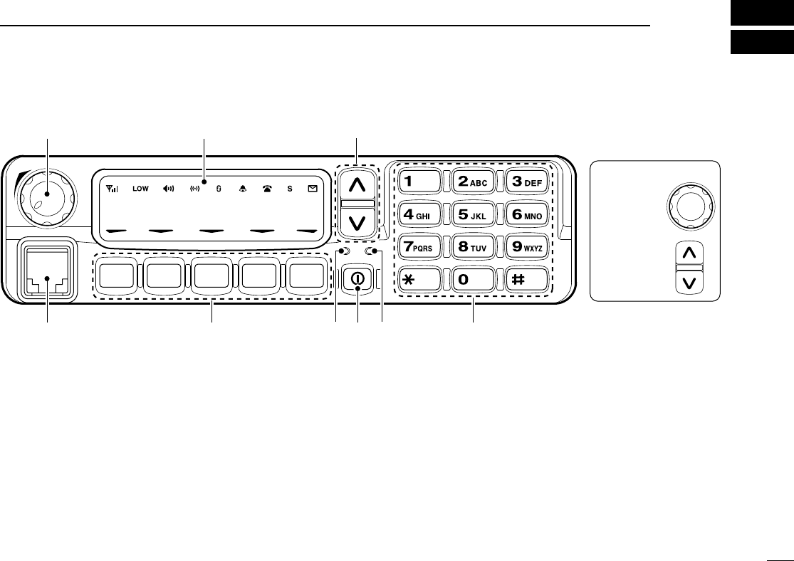
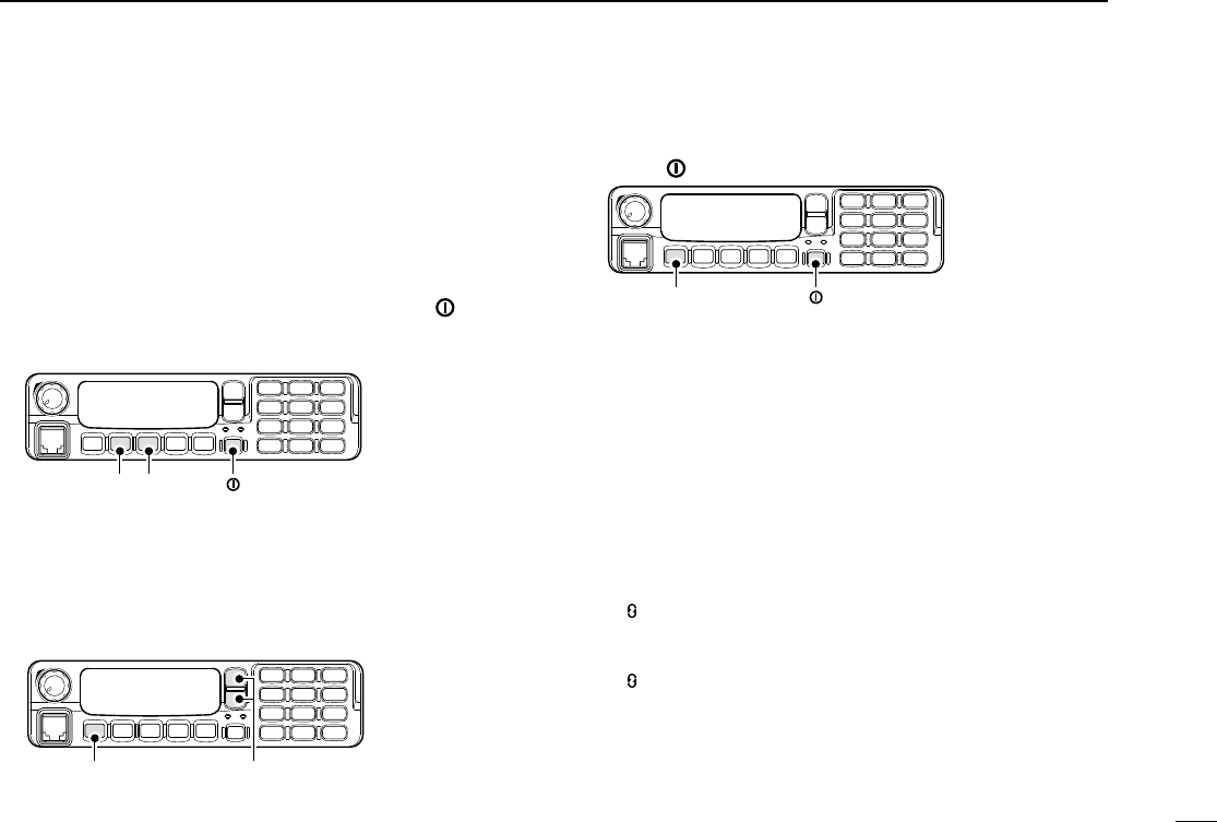
■Front panel
qAF VOLUME CONTROL KNOB
Rotate the knob to adjust the audio output level.
• Minimum audio level is pre-programmed.
wFUNCTION DISPLAY (p. 2)
Displays a variety of information, such as an operating
channel number/name, 5-tone code, DTMF numbers and
audible condition, etc.
eDIAL or UP/DOWN KEYS
• IC-F1721/D, F2721/D: DIAL
Rotate to select an operating channel, etc.
• IC-F1821/D, F2821/D: UP/DOWN Keys
Push to select an operating channel, etc.
*The desired function can be assigned by your dealer. (p. 3)
r10-KEYPAD (IC-F1821/D or IC-F2821/D only)
The keypad allows you to enter digits to:
• Select memory channels
• Select tone channels
• Select DTMF codes (during in the DTMF code channel selection
mode)
• Set TX codes
• Set BIIS status number
• Input text message for SDM operation
• Start up with the password
tBUSY INDICATOR
Lights green while receiving a signal, or when the squelch
is open.
!IC-F1721D.qxd 04.9.2 5:58 PM Page 1 (1,1)
2
1PANEL DESCRIPTION
yPOWER SWITCH [POWER]
Push to turn the power ON and OFF.
• The following functions are available at power ON as options:
- Automatic scan start
- Password prompt
- Set mode
uTRANSMIT INDICATOR
Lights red while transmitting.
iDEALER-PROGRAMMABLE KEYS
Desired functions can be programmed independently by
your dealer. (p. 3)
In this instruction manual, these keys are from the left,
called [P0]/[P1]/[P2]/[P3]/[P4].
oMICROPHONE CONNECTOR
Connect the supplied microphone or optional DTMF micro-
phone.
NEVER connect non-specified microphones. The pin
assignments may be different and the transceiver may
be damaged.
DDMICROPHONE
The supplied microphone has a PTT switch and a hanger
hook.
• The following functions are available when the microphone is on or
off hook:
- Automatic scan start when on hook.
- Automatic priority channel selection when off hook.
- Sets to ‘Inaudible’condition (mute condition) when on hook.
- Sets to ‘Audible’condition (unmute condition) when off hook.
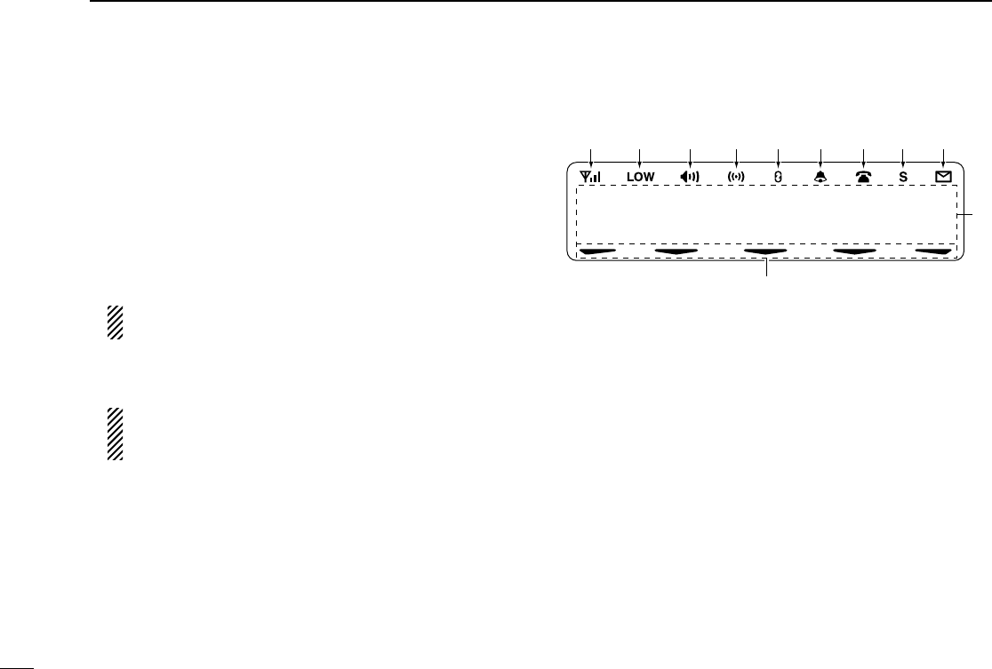
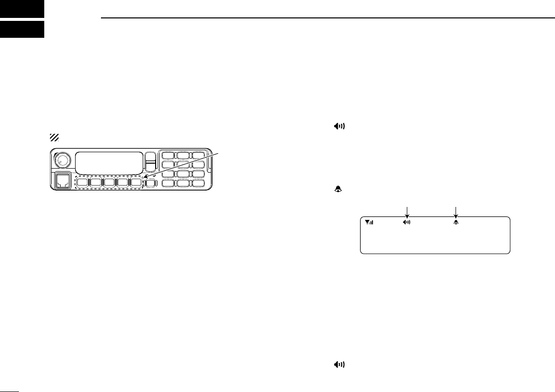
■Function display
qSIGNAL STRENGTH INDICATOR
Indicates relative signal strength level.
wLOW POWER INDICATOR
Appears when low output power is selected.
• When the battery power decreases to a specified level, low
power is selected automatically.
eAUDIBLE INDICATOR
➥Appears when the channel is in the ‘audible’(unmute)
condition.
➥Appears when the specified 2/5-tone/BIIS code is
received.
rCOMPANDER INDICATOR
Appears when the compander function is activated.
tSCRAMBLER INDICATOR
Appears when the voice scrambler function is activated.
136.1 Nar
q w e r t y uio
!1
!0
!IC-F1721D.qxd 04.9.2 5:58 PM Page 2 (1,1)

3
1
PANEL DESCRIPTION
yBELL INDICATOR
Appears/blinks when the specific 2/5-tone/BIIS code is
received, according to the pre-programming.
uCALL CODE MEMORY INDICATOR
Appears when the call code memory is selected.
iSCROLL INDICATOR
Appears when a received SDM including more than 12
characters is displayed.
oSDM INDICATOR
Appears when an SDM is received, or a transmit SDM is
selected.
!0 ALPHANUMERIC DISPLAY
Displays an operating channel number, channel name, Set
mode contents, DTMF code, etc.
The indication type can be selected from 1 line or 2 lines.
Ask your dealer for details.
In this instruction manual, the LCD illustration is described
with 2 lines.
!1 ACTIVATED KEY INDICATOR
Appears above the key assigned as the [DIGITAL] key
when that key has been activated.
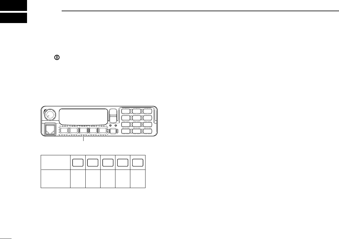
■Programmable function keys
The following functions can be assigned to [DIAL]*, [P0],
[P1], [P2], [P3] and [P4] programmable function keys.
Consult your Icom dealer or system operator for details con-
cerning your transceivers programming.
If the programmable function names are bracketed in the fol-
lowing explanations, the specific key is used to activate the
function depends on the programming.
*The assignable functions are restricted to [DIAL].
(✩marked functions are available.)
✩CH UP AND DOWN KEYS
➥Push (or Rotate)* to select an operating channel.
➥Push (or Rotate)* to select a transmit code channel after
pushing [TX Code CH Select].
➥Push (or Rotate)* to select a DTMF channel after pushing
[DTMF Autodial].
➥Push (or Rotate)* to select a scan group after pushing and
holding [Scan A Start/Stop]/[Scan B Start/Stop].
➥Push (or Rotate)* to select a BIIS code, status number or
SDM after pushing [Digital].
*Rotate when this function is assigned to [DIAL].
✩ZONE UP AND DOWN KEY (This function is for [DIAL] only)
Rotate to select the desired zone.
!IC-F1721D.qxd 04.9.2 5:58 PM Page 3 (1,1)

4
1PANEL DESCRIPTION
ZONE SELECT KEY
Push this key, then push [CH Up] or [CH Down] to select the
desired zone.
What is “zone”?
The desired channels are assigned into a zone according
to the intended use.
SCAN A KEY
➥This key’s operation depends on the Power ON Scan set-
ting.
When the power ON scan function is turned OFF;
Push to start and cancel scanning operation. In case of
transmission during scan, cancels scanning.
When the power ON scan function is turned ON;
Push to pause scanning. Scanning resumes after passing
a specified time period. In case of transmission during
scan, pauses scanning. Scanning resumes after passing
a specified time period specified.
➥Push and hold this key for 1 sec. to indicate the scan
group, then push [CH Up] or [CH Down] to select the
desired group.
SCAN B KEY
➥Push to start and cancel scanning operation. In case of
transmission during scan, pauses scanning. Scanning
resumes after passing a specified time period.
➥Push and hold this key for 1 sec. to indicate the scan
group, then push [CH Up] or [CH Down] to select the
desired group.
SCAN TAG KEY
Push to add or delete the selected channel to the scan group.
PRIORITY CHANNEL KEYS
➥Push to select Priority A or Priority B channel.
➥Push and hold [Prio A (Rewrite)] to rewrite the Prio A chan-
nel.
MR-CH 1/2/3/4 KEYS
Push to select an operating channel directly.
MONITOR KEY
➥Mute and release the CTCSS (DTCS) or 2-tone squelch
mute. Open any squelch/deactivate any mute while push-
ing this key. (LMR operation only)
➥Activates one of (or two of) the following functions on each
channel independently: (PMR or BIIS PMR operation only)
• Push and hold to un-mute the channel (audio is emitted;
‘Audible’condition).
• Push to mute the channel (sets to ‘Inaudible’only).
• Push to un-mute the channel (sets to ‘Audible’only).
• Push after the communication is finished to send a ‘reset
code’.
NOTE: The un-mute condition (‘Audible’condition) may
automatically return to the mute condition (‘Inaudible‘ con-
dition) after a specified period.
!IC-F1721D.qxd 04.9.2 5:58 PM Page 4 (1,1)

5
1
PANEL DESCRIPTION
PUBLIC ADDRESS KEY
When an optional OPC-617
ACC CABLE
is installed, the audio
output via the cable can be controlled from the transceiver
separately from the [VOL] control.
•This audio output can be used as a ‘public address’function when
an external audio amplifier and speaker are connected additionally.
•Push this key, then speak into the microphone while pushing the
PTT switch.
•The [CH Up]/[CH Down] keys allow you to set the audio output level
from minimum to maximum.
RX SPEAKER KEY
When the external connections are made for the ‘public
address’function, the external speaker drive function is also
available simultaneously. The received audio can be heard
via the external speaker when this key is pushed.
•This function is useful when you are out of the vehicle.
•The audio output level is linked to the transceiver’s volume control.
LIGHT KEY
Push to turn the transceiver’s backlight ON temporarily when
the backlight function is turned OFF in user set mode.
LOCK KEY
Push and hold to electronically lock all programmable keys
except the following:
[Call] (incl. Call A and Call B), [Moni(Audi)] and [Emergency].
OUTPUT POWER SELECTION KEY
Push to select the transmit output power temporarily or per-
manently, depending on the pre-setting.
•Ask your dealer for the output power level for each selection.
C.TONE CHANNEL ENTER KEY
Push to select the continuous tone channel using [CH Up]/
[CH Down] to change the tone frequency/code setting after
pushing this key for permanent operation.
TALK AROUND KEY
Turn the talk around function ON and OFF.
•The talk around function equalizes the transmit frequency to the
receive frequency for transceiver-to-transceiver communication.
WIDE/NARROW KEY
Push to toggle the IF bandwidth between wide and narrow.
• The wide passband width can be selected from 25.0 or 20.0 kHz
using the CS-F1700
CLONING SOFTWARE
. (PMR or BIIS PMR opera-
tion only) Ask your Dealer for details.
DTMF AUTODIAL KEY
➥Push to enter the DTMF channel selection mode. Then
select the desired DTMF channel using [CH Up]/[CH
Down]/[CH Up/Down] keys.
➥After selecting the desired DTMF channel, push this key to
transmit the DTMF code.
DTMF RE-DIAL KEY
Push to transmit the last-transmitted DTMF code.
!IC-F1721D.qxd 04.9.2 5:58 PM Page 5 (1,1)

6
1PANEL DESCRIPTION
CALL KEYS
Push to transmit a 2/5-tone/BIIS ID code.
•Call transmission is necessary before calling another station
depending on your signalling system.
•[Call A] and/or [Call B] may be available when your system employs
selective ‘Individual/Group’calls. Ask your dealer which call is
assigned to each key.
EMERGENCY KEYS
➥Push and hold to transmit an emergency call.
➥When [Emergency Single (Silent)] or [Emergency Repeat
(Silent)] is pushed, an emergency call is transmitted without
a beep emission and LCD indication change.
• If you want to cancel the emergency call, push (or push and
hold) the key again before transmitting the call.
• The emergency call is transmitted one time only or repeatedly
until receiving a control code depending on the pre-setting.
TX CODE ENTER KEY (PMR or BIIS PMR operation only)
Push to enter the ID code edit mode directly, for both 5-tone
and MSK. Then set the desired digit using [CH Up]/
[CH Down]/[CH Up/Down] or 10-keypad*. (p. 11)
*IC-F1821/D or IC-F2821/D only
TX CODE CHANNEL SELECT KEY
➥Push to enter the ID code channel selection mode directly.
Then set the desired channel using [CH Up]/[CH Down]/
[CH Up/Down]. (p. 10)
➥While in ID code channel selection mode, push for 1 sec. to
enter the ID code edit mode for 5-tone and MSK. Then set
the desired digit using [CH Up]/[CH Down]/[CH Up/Down]
or 10-keypad*. (p. 11)
*IC-F1821/D or IC-F2821/D only
✩TX CODE CHANNEL UP/DOWN KEYS
Push (or Rotate)* to select a TX code channel directly.
*Rotate when this function is assigned to [DIAL].
ID MEMORY READ KEY (PMR or BIIS PMR operation only)
➥Recalls detected ID codes.
•Push this key, then push [CH Up]/[CH Down] for selection.
•Up to 5 ID’s are memorized.
➥Push and hold to erase the selected memorized ID’s.
VOICE SCRAMBLER FUNCTION
Push to toggle the voice scrambler function ON and OFF.
COMPANDER KEY
Push to toggle the compander function ON and OFF.
The compander function reduces noise components from the
transmitting audio to provide clear communication.
!IC-F1721D.qxd 04.9.2 5:58 PM Page 6 (1,1)

7
1
PANEL DESCRIPTION
USER SET MODE KEY
➥Push and hold to enter user set mode.
• During user set mode, push this key to select an item, and push
[CH Up]/[CH Down] to change the value or condition.
➥Push and hold this key again to exit user set mode.
User set mode is also available via the ‘Power ON function.’
Please refer to p. 13 also.
OPT OUT KEYS
Push to control the optional unit connector output signal level.
DIGITAL KEY (BIIS operation only)
➥Push to select the call ID list, transmit message and stand-
by condition. Toggles between queue channel and
received message record indication after queue channel is
selected.
➥Push and hold to select queue channel indication.
✩STATUS UP/DOWN KEYS (BIIS operation only)
➥While in the standby condition, push (or rotate)* to display
the transmit status indication and select a status number.
➥When a received SDM is displayed, push (or rotate)* to
cancel the automatic scroll and scroll the message manu-
ally.
➥When an SDM that contains more than 12 characters is
displayed, push (or rotate)* to scroll the message manually.
*Rotate when this function is assigned to [DIAL].
DFor Digital mode operation only
INDIVIDUAL KEY
➥Push to enter the individual ID code selection mode direct-
ly. Then select the desired individual ID code using [CH
Up]/
[CH Down]/[CH Up/Down]. (p. 12)
➥Push to stop the beep emission when receiving a matched
individual ID code.
TALKGROUP KEY
➥Push to enter the talkgroup ID code selection mode direct-
ly. Then select the desired talkgroup ID code using [CH
Up]/ [CH Down]/[CH Up/Down]. (p. 12)
➥Push to stop the beep emission when receiving a matched
talkgroup ID code.
!IC-F1721D.qxd 04.9.2 5:58 PM Page 7 (1,1)
8
2BASIC OPERATION
■Turning power ON
qPush [ ] to turn the power ON.
wIf the transceiver is programmed for a start up password,
input the digit codes as directed by your dealer.
• 10-keypad* can be used for password input.
*IC-F1821/D or IC-F2821/D only:
• The keys as below can be used for password input:
• The transceiver detects numbers in the same block as identical.
Therefore “01234” and “56789” are the same.
eWhen the “PASSWORD” indication does not clear after
inputting 4 digits, the input code number may be incorrect.
Turn the power off and start over in this case.
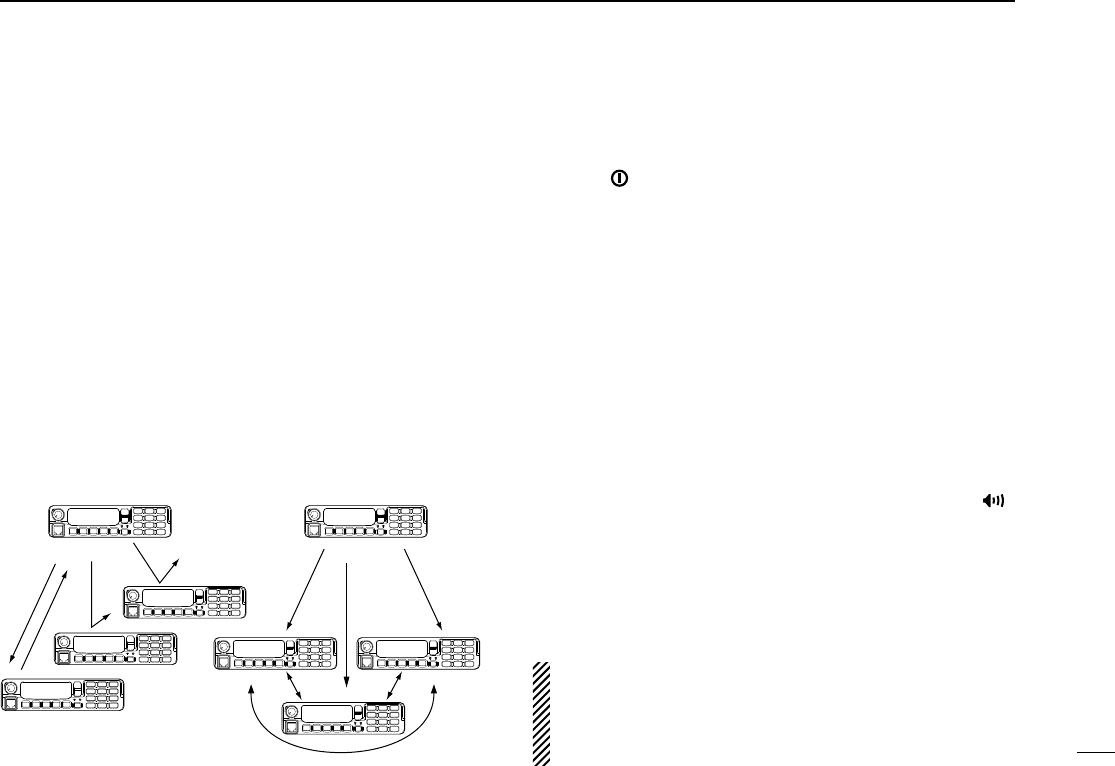
■Channel selection
Several types of channel selections are available. Methods
may differ according to your system set up.
NON-ZONE TYPE:
Push [CH Up] or [CH Down], or rotate [CH Up/Down] to select
the desired operating channel, in sequence; or, push one of
[MR-CH 1] to [MR-CH 4] keys to select a channel directly.
ZONE TYPE:
Push [Zone] then push [CH Up] or [CH Down], or rotate [Zone
Up/Down] to select the desired zone.
AUTOMATIC SCAN TYPE:
Channel setting is not necessary for this type. When turning
power ON, the transceiver automatically starts scanning.
Scanning stops when receiving a call.
KEY
NUMBER 0
5
4
9
3
8
2
7
1
6
P0 P4P3P2P1
P0 P4P3P2P1
*In this instruction manual, these keys are
from the left, called [P0]/[P1]/[P2]/[P3]/[P4].
!IC-F1721D.qxd 04.9.2 5:58 PM Page 8 (1,1)
9
2
BASIC OPERATION
■Call procedure
When your system employs tone signaling (excluding CTCSS
and DTCS), the call procedure may be necessary prior to voice
transmission. The tone signalling employed may be a selec-
tive calling system which allows you to call specific station(s)
only and prevent unwanted stations from contacting you.
qSelect the desired TX code channel, 2/5-tone code,
Individual ID code* or Talkgroup ID code* according to
your System Operator’s instructions.
• This may not be necessary depending on programming.
• Refer to pgs. 10–12 for selection.
*Digital mode operation only.
wPush the call key (assigned to one of the dealer program-
mable keys) or [PTT].
eAfter transmitting, the remainder of your communication
can be carried out in the normal fashion.
■Receiving and transmitting
Receiving:
qPush [ ] to turn the power ON.
wPush [CH Up] or [CH Down], or rotate [CH Up/Down] to
select a channel, in sequence.
eWhen receiving a call, adjust the audio output level to a
comfortable listening level.
Transmitting:
Wait for the channel to become clear to avoid interference.
qTake the microphone off hook.
• 2-tone, 5-tone mute may be released. (The ‘audible’condition is
selected and BUSY indicator lights green.)
• A priority channel may be selected automatically.
wWait for the channel to become clear.
• The channel is busy when BUSY indicator lights green.
ePush [CALL] when initiating a call from your side.
• Coded audio may be heard from the transceiver, then “”
appears.
• This operation may not be necessary depending on your signal-
ing system. Ask your dealer for details.
rWhile pushing and holding [PTT], speak into the micro-
phone at your normal voice level.
tRelease [PTT] to receive.
IMPORTANT: To maximize the readability of your signal;
1. Pause briefly after pushing [PTT].
2. Hold the microphone 5 to 10 cm (2 to 4 inches) from
your mouth, then speak into the microphone at a normal
voice level.
Selective calling Non-selective calling
!IC-F1721D.qxd 04.9.2 5:58 PM Page 9 (1,1)

10
2BASIC OPERATION
DTransmitting notes
• Transmit inhibit function
The transceiver has several inhibit functions which restrict
transmission under the following conditions:
- The channel is in mute condition (‘Inaudible’condition;
“”does not appear.)
- The channel is busy.
- Un-matched (or matched) CTCSS is received.
- The selected channel is a ‘receive only’channel.
• Time-out timer
After continuous transmission for the pre-programmed time
period, the time-out timer is activated, causing the transceiv-
er to stop transmitting.
• Penalty timer
Once the time-out timer is activated, transmission is further
inhibited for a period determined by the penalty timer.
DTX code channel selection
If the transceiver has [TX Code CH Select] assigned to it, the
indication can be toggled between the operating channel
number (or name) and TX code channel number (or name).
When the TX code channel number (or name) is displayed,
[CH Up], [CH Down] or [CH Up/Down] selects the TX code
channel.
USING [TX CODE CH SELECT] KEY:
qPush [TX Code CH Select]— a TX code channel number
(or name) appears.
wPush [CH Up] or [CH Down], or rotate [CH Up/Down] to
select the desired TX code channel.
ePush [Call] (or [PTT] during MSK operation) to transmit the
selected TX code.
USING [TX CODE CH UP]/[TX CODE CH DOWN] KEY:
If the transceiver has a [TX Code CH Up], [TX Code CH
Down] or [TX Code CH Up/Down] key assignment, the pro-
grammed TX code channel can be selected directly when
pushed or rotated.
NOTE for PMR or BIIS PMR operation:
• The LCD indication is not changed when the operating channel
number (or name) is displayed.
• To check the selected TX code, push [TX Code CH Select].
!IC-F1721D.qxd 04.9.2 5:58 PM Page 10 (1,1)

11
2
BASIC OPERATION
DTX code number edit
(PMR or BIIS PMR operation only)
If the transceiver has [TX Code CH Select] or [TX Code
Enter] assigned to it, TX code contents can be edited within
the allowable digits.
USING [TX CODE CH SELECT] KEY:
qPush [TX Code CH Select] to enter the TX code channel
selection mode.
• Select the desired channel before entering the TX code channel
selection mode if necessary.
wPush [TX Code CH Select] for 1 sec. to enter the TX code
edit mode.
ePush [TX Code CH Select] to select the desired digit to be
edited.
• The editable digit blinks.
rPush [CH Up], [CH Down] or 10-keypad*, or rotate [CH
Up/Down] to set the desired digit.
tPush [TX Code CH Select] to set the digit. The editable
digit will move to the right automatically.
• When the 10-keypad* is used to set, the editable digit will move
to the right automatically without pushing [TX Code CH Select].
yRepeat rand tto input all allowable digits.
uPush [Call] or [PTT] to transmit the edited TX code.
*IC-F1821/D or IC-F2821/D only
USING [TX CODE ENTER] KEY:
qSelect the desired TX code channel via [TX Code CH
Select]+[CH Up] or [CH Down], [TX Code CH Up], [TX
Code CH Down] or [TX Code CH Up/Down].
wPush [TX Code Enter] to enter the TX code edit mode.
ePush [TX Code Enter] to select the desired digit to be edit-
ed.
• The editable digit blinks.
rPush [CH Up], [CH Down] or 10-keypad*, or rotate [CH
Up/Down] to set the desired digit .
tPush [TX Code Enter] to set the digit. The editable digit will
move to the right automatically.
• When the 10-keypad* is used to set, the editable digit will move
to the right automatically without pushing [TX Code CH Select].
yRepeat rand tto input all allowable digits.
uPush [Call] or [PTT] to transmit the edited TX code.
*IC-F1821/D or IC-F2821/D only
!IC-F1721D.qxd 04.9.2 5:58 PM Page 11 (1,1)

12
2BASIC OPERATION
DIndividual ID code selection
(Digital mode operation only)
If the transceiver has [Individual] assigned to it, the indication
can be toggled between the operating channel number (or
name) and Individual ID code (or name). When the Individual
ID code (or name) is displayed, [CH Up], [CH Down] or [CH
Up/Down] selects the desired Individual ID code.
qPush [Individual]— an Individual ID code (or name)
appears.
wPush [CH Up] or [CH Down], or rotate [CH Up/Down] to
select the desired Individual ID code.
ePush [PTT] to transmit the selected Individual ID code.
DTalkgroup ID code selection
(Digital mode operation only)
If the transceiver has [Talkgroup] assigned to it, the indication
can be toggled between the operating channel number (or
name) and Talkgroup ID code (or name). When the Talkgroup
ID code (or name) is displayed, [CH Up], [CH Down] or [CH
Up/Down] selects the desired Talkgroup ID code.
qPush [Talkgroup]— a Talkgroup ID code (or name)
appears.
wPush [CH Up] or [CH Down], or rotate [CH Up/Down] to
select the desired Talkgroup ID code.
ePush [PTT] to transmit the selected Talkgroup ID code.
DDTMF transmission
If the transceiver has [DTMF Autodial] assigned to it, the auto-
matic DTMF transmission function is available. Up to 8 DTMF
channels are available.
TO SELECT A TX CODE:
qPush [DTMF Autodial]— a DTMF channel appears.
wPush [CH Up] or [CH Down], or rotate [CH Up/Down] to
select the desired DTMF channel.
ePush [DTMF Autodial] to transmit the DTMF code in the
selected DTMF channel.
!IC-F1721D.qxd 04.9.2 5:58 PM Page 12 (1,1)
13
2
BASIC OPERATION
■User set mode
User set mode is accessed with [User Set Mode] and allows
you to set seldom-changed settings. In this case you can
“customize” the transceiver operation to suit your preferences
and operating style.
Entering the user set mode:
qWhile pushing and holding [P1] and [P2], push [ ] to turn
the power ON. Then, push and hold [P0] to enter user set
mode, allowing you to set seldom-changed settings.
wPush [P0] several times to select the appropriate item.
Then, push [Up] or [Down] or rotate [DIAL] to set the
desired level/condition.
• Available set mode functions are Backlight, LCD Contrast,
Beep, Beep Level, SQL Level, AF Min Level, Mic Gain and
Horn.
ePush [ ] (or push and hold [P0]) again to exit set mode.
User set mode is also available via a programmable key.
Please refer to p. 7 [User Set Mode] section.
■Scrambler function
The voice scrambler function provides private communication
between stations. The frequency inversion type is equipped
to all versions, moreover, the optional Rolling or Non-rolling
type can be available.
qPush [Scrambler] to turn the scrambler function ON.
• “” appears.
wPush [Scrambler] again to turn the scrambler function
OFF.
• “” disappears.
[P1] [ ]
[P0] [Up]/[Down] or [DIAL]
[P1] [P2] [ ]
!IC-F1721D.qxd 04.9.2 5:58 PM Page 13 (1,1)
14
3BIIS OPERATION
■Default setting
The following functions are assigned to each programmable
key as the default. However, the assigned function can be
changed by your dealer. Ask your dealer for details.
NOTE: [TX Code Enter] must be assigned to any key.
[P0]; Call : Push to transmit a 5-tone/BIIS call
when the selected channel is a 5-
tone or MSK channel, respectively.
[P1]; Digital : Push to select the call list ID/transmit
message, or to display the receive
message record for selection.
[P3]; TX Code Enter : Push to enter the ID code edit mode
directly for both 5-tone and MSK.
[P4]; Moni(Audi) : Push this key after the communica-
tion to send a ‘Clear down’signal
during MSK channel operation.
[P2]; Null : No function is assigned.
[Up]/[Down]/[DIAL]; CH Up/Down
: While in the standby condition,
selects the operating channel.
After pushing [Digital] or [TX Code
CH Select], selects call list or TX
code channel, respectively.
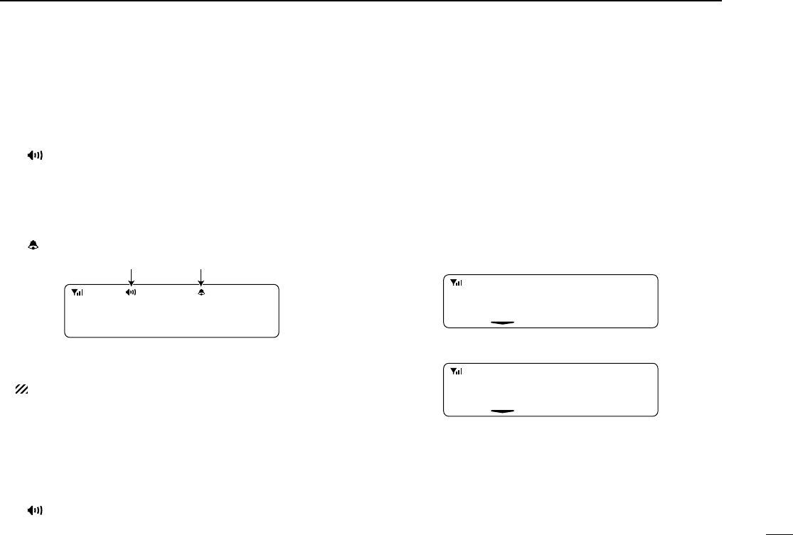
■Receiving a call
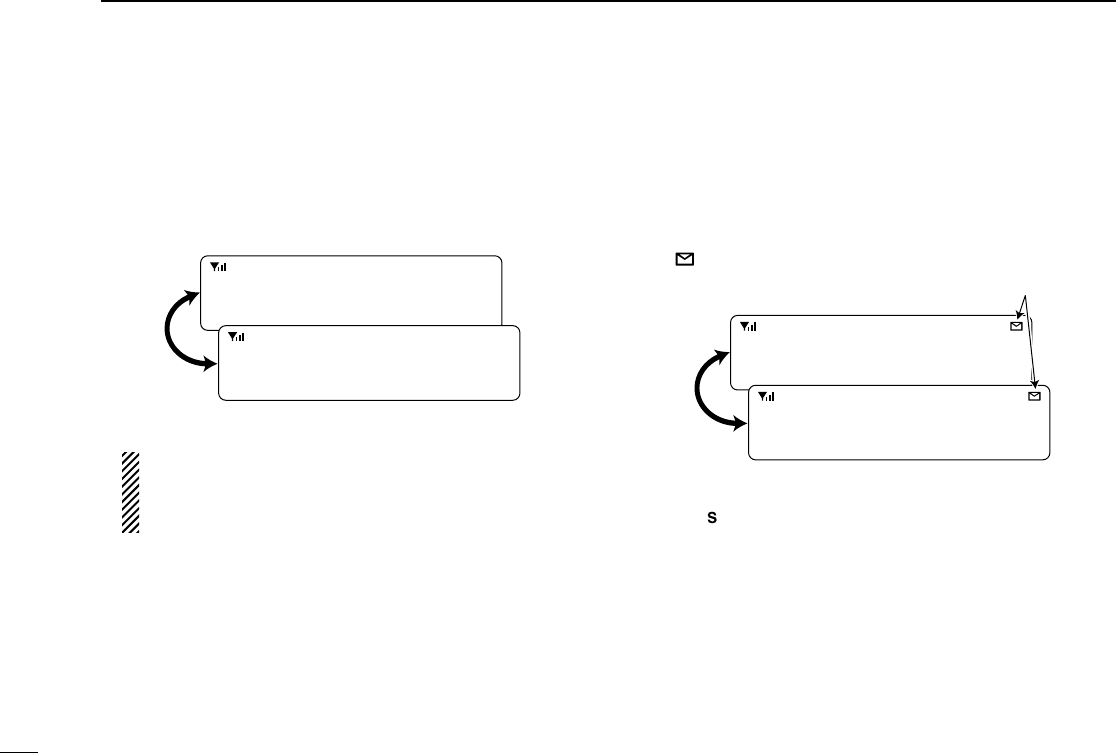
DDIndividual call
qWhen an individual call is received;
•Beeps sound.
•“ ” appears and the mute is released.
•The programmed text message (e.g.“CALLING”) and the calling
station ID (or text) is displayed when the display type is 2lines.
•The programmed text message (e.g.“CALLING”) and the calling
station ID (or text) is displayed alternately when the display type
is 1line, depending on the setting.
•“ ” appears or blinks depending on the setting.
wPush and hold [PTT], then speak into the microphone at a
normal voice level.
•TX indicator lights red.
eRelease [PTT] to return to receive.
•BUSY indicator lights green while receiving a signal.
rTo finish the conversation, push [P4] (Moni(Audi)) to send
the ‘Clear down’signal.
•Either station can send a ‘Clear down’signal.
•“CLR DOWN” is displayed for 2 sec. (approx.).
•“ ” disappears and the transceiver returns to the standby con-
dition.
Appears or blinksAppears
0 500
CALLING
P0 P4P3P2P1
In this instruction
manual, these keys
are from the left,
called [P0]/[P1]/
[P2]/[P3]/[P4].
!IC-F1721D.qxd 04.9.2 5:58 PM Page 14 (1,1)
15
3
BIIS OPERATION
DDGroup call
qWhen a group call is received;
•Beeps sound.
•“ ” appears and the mute is released.
•The programmed text message (e.g.“GROUP”) and the calling
station ID (or text) is displayed when the display type is 2lines.
•The programmed text message (e.g.“GROUP”) and the calling
station ID (or text) is displayed alternately when the display type
is 1line, depending on the setting.
•“ ” appears or blinks depending on the setting.
wPush and hold [PTT], then speak into the microphone at a
normal voice level.
NOTE: Only one station is permitted to speak.
•TX indicator lights red.
eRelease [PTT] to return to receive.
•BUSY indicator lights green while receiving a signal.
rTo finish the conversation, push [MONITOR] (Moni(Audi))
to send the ‘Clear down’signal.
•Either station can send a ‘Clear down’signal.
•“CLR DOWN” is displayed for 2 sec. (approx.)
•“ ” disappears and the transceiver returns to the standby con-
dition.
DDDisplaying the received call record
— Queue indication
The transceiver memorizes the calling station IDs for record.
Up to 3 calls can be memorized, and the oldest call record is
erased when a 4th call is received. However, once the trans-
ceiver is powered OFF, the all records are cleared.
qPush [P1] (Digital) for 1 sec.
•Displays following indication.
When a record is available
When no record is available
wPush [Up] or [Down], or rotate [DIAL] to select the desired
call.
ePush [P1] (Digital) for 1 sec. again to return to the standby
condition.
•When no operation is performed for 30 sec., the transceiver
returns to the standby condition automatically.
<QUEUE>
NO QUEUE
<QUEUE>
-QUEUE!-
Appears or blinksAppears
1120
GROUP
!IC-F1721D.qxd 04.9.2 5:58 PM Page 15 (1,1)
16
3BIIS OPERATION
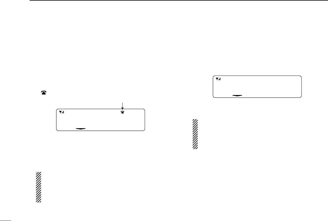
■Transmitting a call
Total of a 3 ways for code selection are available—selecting
the call code from memory, entering the call code from the
keypad and calling back from the queue channel record.
DDUsing call memory
qWhile in the standby condition, push [P1] (Digital) to enter
the call code memory channel selection mode.
•“ ” appears.
wPush [Up] or [Down], or rotate [DIAL] to select the desired
call code.
ePush [P0] (Call) or [PTT]* to call.
*PTT call can be made only when PTT call capability is permitted.
NOTE: When no answer back is received, the trans-
ceiver repeats the call 3 times (default) automatically,
and “WAIT”is displayed during each call. However, an
error beep sounds and “FAILED”is displayed when no
answer back is received after the calls.
rPush [PTT] to transmit; release to receive.
tPush [P4] (Moni(Audi)) to send the ‘Clear down’signal.
DDCalling back from the queue channel
qWhile in the standby condition, push [P1] (Digital) for
1 sec. to enter the queue memory channel selection mode.
wPush [Up] or [Down] or rotate [DIAL] to select the desired
record.
ePush [P0] (Call) or [PTT]* to call.
*PTT call can be made only when PTT call capability is permitted.
NOTE: When no answer back is received, the trans-
ceiver repeats the call 3 times (default) automatically,
and “WAIT”is displayed during each call. However, an
error beep sounds and “FAILED”is displayed when no
answer back is received after the calls.
rPush [PTT] to transmit; release to receive.
tPush [P4] (Moni(Audi)) to send the ‘Clear down’signal.
<QUEUE>
-QUEUE!-
FLEET 100
Call code text is displayed.
Appears
!IC-F1721D.qxd 04.9.2 5:58 PM Page 16 (1,1)

17
3
BIIS OPERATION
DDDirect code entry
qWhile in the standby condition, push [P3] (TX Code Enter)
to enter the TX code edit mode.
•Editable code digit blinks.
wPush [P3] (TX Code Enter) to select the desired digit to be
edited.
•Editable digit differs according to the setting.
eSet the desired digit using [CH Up]/[CH Down]/[DIAL] or
10-keypad*.
*IC-F1821/D or IC-F2821/D only
rPush [P3] (TX Code Enter) to set the digit, then the
editable digit will move to the right automatically.
• When the 10-keypad is used to set, the editable digit will move to
the right automatically without pushing [P3] (TX Code Enter).
tRepeat eand rto input all allowable digits.
yPush [P0] (Call) or [PTT]* to call.
*PTT call can be made only when PTT call capability is permitted.
NOTE: When no answer back is received, the trans-
ceiver repeats the call 3 times (default) automatically,
and “WAIT”is displayed during each call. However, an
error beep sounds and “FAILED”is displayed when no
answer back is received after the calls.
uPush [PTT] to transmit; release to receive.
iPush [P4] (Moni(Audi)) to send the ‘Clear down’signal.
For your information
When the “UpDate” setting for the call code is enabled, the
set code is overwritten into the call code memory.
0500
!IC-F1721D.qxd 04.9.2 5:58 PM Page 17 (1,1)
18
3BIIS OPERATION
■Receiving a message
DDReceiving a status message
qWhen a status message is received;
• Beeps sound.
• The calling station ID (or text) and the status message is dis-
played alternately, depending on the setting.
wPush [P4] (Moni(Audi)) to return to the standby condition.
NOTE: Only the calling station ID (or text) is displayed (no
message is displayed alternately) when the scroll timer is
set to ‘OFF.’In this case, push [Status Up]/[Status Down]
to display the status message manually.
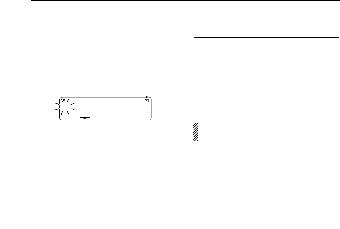
DDReceiving an SDM (Short Data Message)
qWhen an SDM is received;
• Beeps sound.
• The calling station ID (or text) and the SDM is displayed alter-
nately, depending on the setting.
• “” appears
wWhen the received SDM includes more than 12 charac-
ters, “” appears and the message scrolls automatically,
when the automatic scroll function is activated.
• Push [Status Up]/[Status Down] to scroll the message manually.
ePush [P4] (Moni(Audi)) to return to the standby condition.
SDM 8
BASE
BAS E
BASE
Appears
TX Status 01
BASE
BAS E
BASE
!IC-F1721D.qxd 04.9.2 5:58 PM Page 18 (1,1)

19
3
BIIS OPERATION
DDReceived message selection
The transceiver memorizes the received messages for
record. Up to 6 messages for status and SDM, or 95 charac-
ter SDM’s can be memorized. The oldest message is erased
when the 7th message is received. However, once the trans-
ceiver is powered OFF, all messages are cleared.
qPush [P1] (Digital) for 1 sec.
•Displays queue memory.
wPush [P1] (Digital) momentarily.
•Displays message memory.
When a message is available
When no message is available
ePush [Up] or [Down], or rotate [DIAL] to select the desired
message.
•When selecting the SDM that includes more than 12 characters,
“” appears and the message scrolls automatically, when the
automatic scroll function is activated.
• Push [Status Up]/[Status Down] to scroll the message manually.
rPush [P1] (Digital) for 1 sec. again to return to the standby
condition.
•When no operation is performed for 30 sec., the transceiver
returns to the standby condition automatically.
MESSAGE
-NO MSG-
MESSAGE
-MSG!-
!IC-F1721D.qxd 04.9.2 5:58 PM Page 19 (1,1)

20
3BIIS OPERATION
■Transmitting a status
DDGeneral
The status message can be selected with the programmed
text, and the message text is also displayed on the function
display of the called station.
Up to 24 status types (1 to 24) are available, and the status
messages 22 and 24 have designated meanings.
Status 22: Emergency*
Status 24: GPS request
*The status 22 can also be used as a normal status message by
disabling the designated meaning. However, the status 24 is fixed.
The status call can be sent with both individual and group
calls.
DDTransmitting a status
qWhile in the standby condition, push [P1] (Digital), then
push [Up] or [Down], or rotate [DIAL] to select the desired
station/group code.
wPush [P1] (Digital) again, then push [UP] or [DOWN] to
select the desired status message.
Or, you can select the desired status message using
[Status Up]/[Status Down] key directly.
ePush [P0] (Call) or [PTT]* to transmit the status message
to the selected station/group.
*PTT call can be made only when PTT call capability is permitted.
•2 beeps will sound and the transceiver returns to the standby
condition automatically when the transmission is successful.
TX Status 01
Status message is displayed.
!IC-F1721D.qxd 04.9.2 5:58 PM Page 20 (1,1)

21
3
BIIS OPERATION
DDGeneral
The short data message, SDM, can be sent to an individual
station or group stations. Also, 8 SDM memory channels are
available and the messages can be edited via PC program-
ming.
DDTransmitting an SDM
qWhile in the standby condition, push [P1] (Digital), then
push [Up] or [Down] or rotate [DIAL] to select the desired
station/group code.
wPush [P1] (Digital) again, then push [Up] or [Down] or
rotate [DIAL] to select the desired SDM.
Or, you can select the desired SDM using [Status Up]/
[Status Down] key directly.
ePush [P0] (Call) or [PTT]* to transmit the SDM to the
selected station/group.
*PTT call can be made only when PTT call capability is permitted.
•2 beeps will sound and the transceiver returns to the standby
condition automatically when the transmission is successful.
SDM 8
SDM is displayed.
Appears
■Transmitting an SDM (Short Data Message)
!IC-F1721D.qxd 04.9.2 5:58 PM Page 21 (1,1)
22
3BIIS OPERATION
DDProgramming an SDM memory
(IC-F1821/D or IC-F2821/D only)
qDuring standby condition, push [P1] (Digital) twice, then
push [Up] or [Down], or rotate [DIAL] to select the desired
SDM to be edited.
wPush [M] or [#] to enter the message editing condition.
•The first character blinks when [#] is pushed, the last character
blinks when [M] is pushed as below.
ePush the appropriate digit key, [0] to [9], to enter the
desired character.
•See the table at right for the available characters.
•Pushing [UP] also enters space, pushing [DOWN] deletes the
selected character.
rPush [#] to move the cursor to the right, push [M] to move
the cursor to the left.
tRepeat steps eand rto set the desired text message.
yPush [P1] (Digital) for 1 sec. to overwrite the set content
into the memory.
•Push [P1] (Digital) momentarily to cancel the editing and return to
the original message indication.
•Available characters
NOTE: Once the pre-programmed character including a
decimal point is rewrote with the 10-keypad, the decimal
point cannot be displayed again.
Key
[0]
[1]
[2]
[3]
[4]
[5]
[6]
[7]
[8]
[9]
Characters
0 ! ? ' " , ; : _ ( ) < > [ ]
1 (space) # * / + - = & % $ @ ^
2 A B C a b c
3 D E F d e f
4 G H I g h i
5 J K L j k l
6 M N O m n o
7 P Q R S p q r s
8 T U V t u v
9 W X Y Z w x y z
/
SDM 8
Blinks
When [#] is pushed.
!IC-F1721D.qxd 04.9.2 5:58 PM Page 22 (1,1)

23
3
BIIS OPERATION
■Position data transmission
When the optional cable and a GPS receiver is connected to
the transceiver, the position (longitude and latitude) data can
be transmitted automatically.
Ask your dealer or system operator for connection details.
The position data is transmitted when;
•Status 24 message is received
*When the status 24 message, GPS request, is received.
•Fully automatic
When automatic position transmission is enabled, send
the position data according to ‘Time Marker’and ‘Interval
Timer’settings.
•PTT is released
When ‘Send with Logoff’is enabled.
-Set the ‘Log-In/Off’item as ‘L-OFF.’
•After sending a status message
When ‘Send with Status’is enabled.
•After sending an SDM
When ‘Send with SDM’is enabled.
•After sending status 22 (Emergency)
When ‘Send with Emergency’is enabled.
■Printer connection
When the optional cable is connected to the transceiver, a
printer can be connected to print out the received SDM con-
tent and the ID of the station who sent the message.
Ask your dealer or system operator for connection details.
■Digital ANI
The own ID can be transmitted each time the PTT is pushed
(log-in) or released (log-off) during individual or group call
communications.
By receiving the ANI, the communication log can be recorded
when using a PC dispatch application.
In addition, when using the ANI with log-in, the PTT side tone
function can be used to inform you that the ID is sent and
voice communication can be performed.
■Auto emergency transmission
When [Emergency Single (Silent)] or [Emergency Repeat
(Silent)] is pushed, an emergency signal is automatically
transmitted for the specified time period.
The status 22 (Emergency) is sent to the selected ID station,
and the position data is transmitted after the emergency sig-
nal when a GPS receiver is connected to the transceiver.
The emergency transmission is performed on the emergency
channel, however, when no emergency channel is specified,
the signal is transmitted on the previously selected channel.
There is no change in the function display or beep emission
during automatic emergency transmission.
!IC-F1721D.qxd 04.9.2 5:58 PM Page 23 (1,1)

24
3BIIS OPERATION
■Stun function
When the specified ID, set as a killer ID, is received, the stun
function is activated.
When the killer ID is received, the transceiver switches to the
password required condition. Entering of the password via the
keypad is necessary to operate the transceiver again in this
case.
■BIIS indication
The following indications are available for the BIIS operation
on an MSK channel.
CONNECT : Individual/group call is successful.
OK : Message (status or SDM) transmission is suc-
cessful.
FAILED : No answer back is received.
WAIT : Appears during retry of the call (2nd call).
CLR DOWN : End the communication.
BUSY : Operating channel is in the busy condition.
■Priority A channel selection
When one of the following operations is performed, the trans-
ceiver selects the Priority A channel automatically.
Priority A is selected when;
•Clear down signal is received/transmitted
- Set the ‘Move to PrioA CH’item as ‘Clear down.’
•Turning the power ON
The Priority A channel is selected each time the transceiv-
er power is turned ON.
•Status call
The Priority A channel is selected when transmitting a sta-
tus call.
-Enable the ‘Send Status on PrioA CH’item in the MSK
configuration.
■Horn output
Automatic honking function is available when the optional
OPC-617
ACC CABLE
is connected. When a status message
is received, the transceiver controls the vehicles horn for the
specified time period to inform a status message is received.
This function is convenient when the operator away from the
transceiver.
Ask your dealer or system operator, or refer to the service
manual for connection and setting details.
!IC-F1721D.qxd 04.9.2 5:58 PM Page 24 (1,1)
25
4
CONNECTION AND MAINTENANCE
r
Supplied speaker SP-22
(Depending on version)
t
Antenna
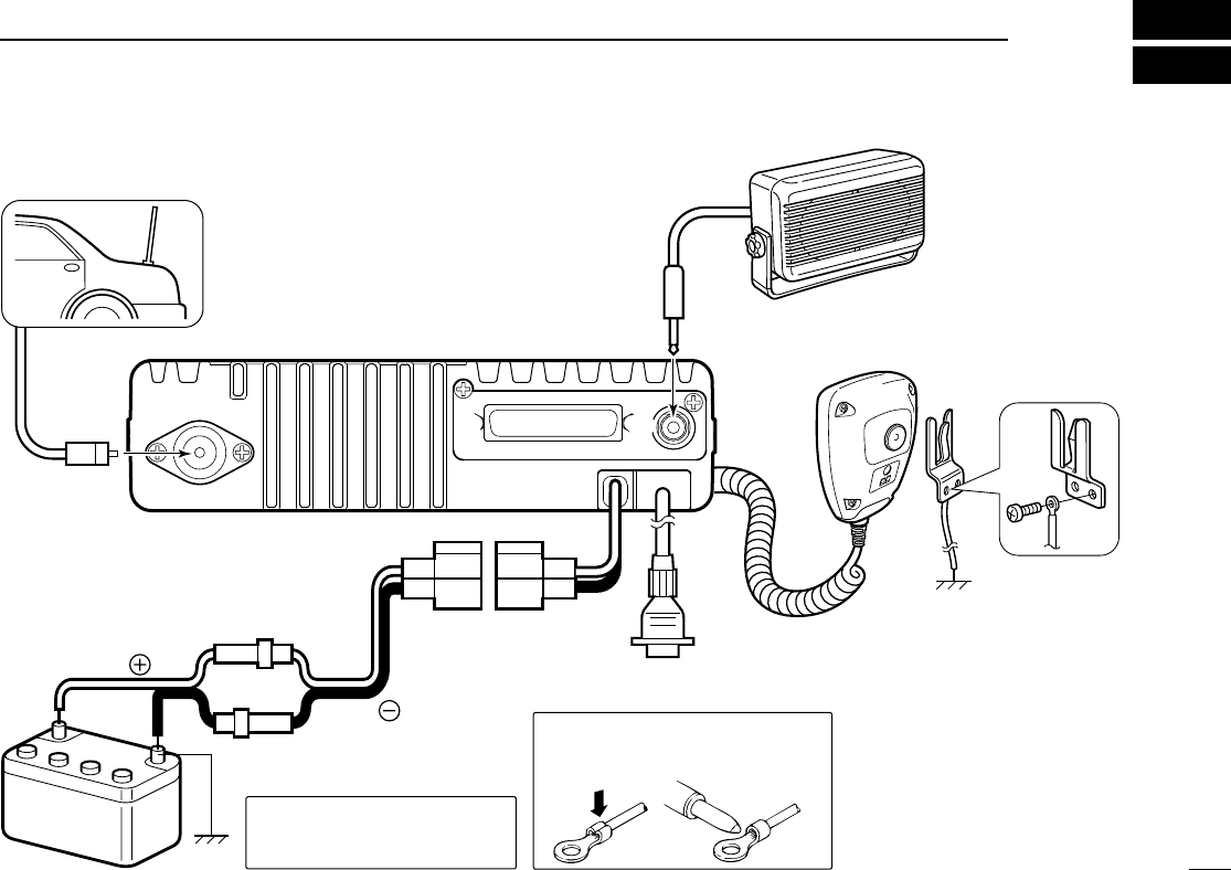
Black
Red
12V
Battery
Solder
Crimp
NOTE: Use the terminals as shown
below for the cable connections.
R CAUTION! NEVER remove
the fuse-holder from the DC
power cable.
q ANTENNA CONNECTOR
Connects to an antenna.
Contact your dealer about
antenna selection and
placement.
qew
e EXTERNAL
SPEAKER JACK
w Reserved for future
function.
Connect a 4—8 ‰
external speaker.
r MICROPHONE HANGER
Connect the supplied mi-
crophone hanger to the
vehicle s ground for mi-
crophone on/off hook
functions. (See p. 2)
t OPTIONAL CABLE
(OPC-617)
Connect an external mo-
dem unit, dimmer control,
etc.
y
y DC POWER RECEPTACLE
Connects to a 12 V DC battery. Pay atten-
tion to polarities. NEVER connect to a 24 V
battery. This could damage the transceiver.
■Rear panel and connection
!IC-F1721D.qxd 04.9.2 5:58 PM Page 25 (1,1)
26
4CONNECTION AND MAINTENANCE
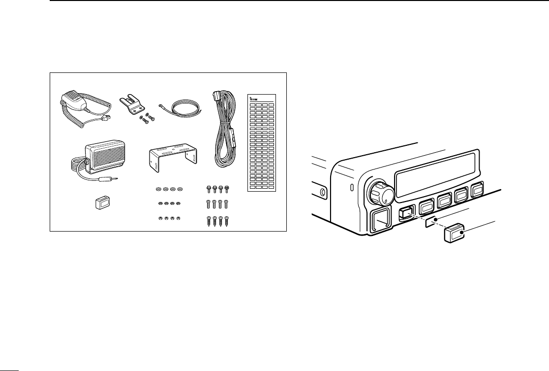
■Supplied Accessories
• Function name stickers
There are no names on the programmable function keys since the
functions can be freely assigned to these keys.
Attach the supplied function name stickers as at right to the appro-
priate keys for easy recognition of that key’s assigned function.
Then, protect the attached stickers from unsticking with the supplied
key cap as below.
Function name sticker
Key cap
qMicrophone ...................... 1
wMicrophone hanger and
screw set ..................... 1 set
eMicrophone hanger cable . 1
rDC power cable (OPC-1194)
............................................1
tFunction name stickers
(KEY STICKER) ....................1
ySpeaker* ........................... 1
uMounting bracket .............. 1
iKey cap ............................. 1
oFlat washers ...................... 4
!0 Spring washers ................. 4
!1 Nuts ................................... 4
!2 Bracket bolts ..................... 4
!3 Mounting screws (M5×12) . 4
!4 Self-tapping screws (M5×20)
........................................... 4
*Depending on version
qw er
uy
i
o
!0
!1
!2
!3
!4
t
KEY-STICKER
!IC-F1721D.qxd 04.9.2 5:58 PM Page 26 (1,1)
27
4
CONNECTION AND MAINTENANCE
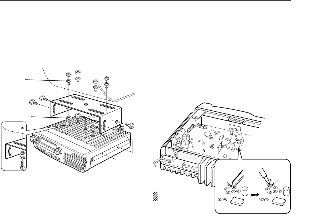
■Mounting the transceiver
The universal mounting bracket supplied with your transceiv-
er allows overhead mounting.
•Mount the transceiver securely with the 4 supplied screws
to a thick surface which can support more than 1.5 kg.
■Optional UT-111 installation
Install the optional UT-111 unit as follows:
qTurn the power OFF, then disconnect the DC power cable.
wUnscrew the 4 cover screws, then remove the bottom
cover.
eCut the pattern on the PCB at the CP57, then solder CP58
as shown below.
rInstall the unit as shown in the diagram below.
tReplace the bottom cover and screws, then re-connect the
DC power cable.
e
r
CP57 CP58
Flat washer
Spring washer
When using
self-tapping screws
See p. 28 when unin-
stalling the unit.
!IC-F1721D.qxd 04.9.2 5:58 PM Page 27 (1,1)
28
4CONNECTION AND MAINTENANCE
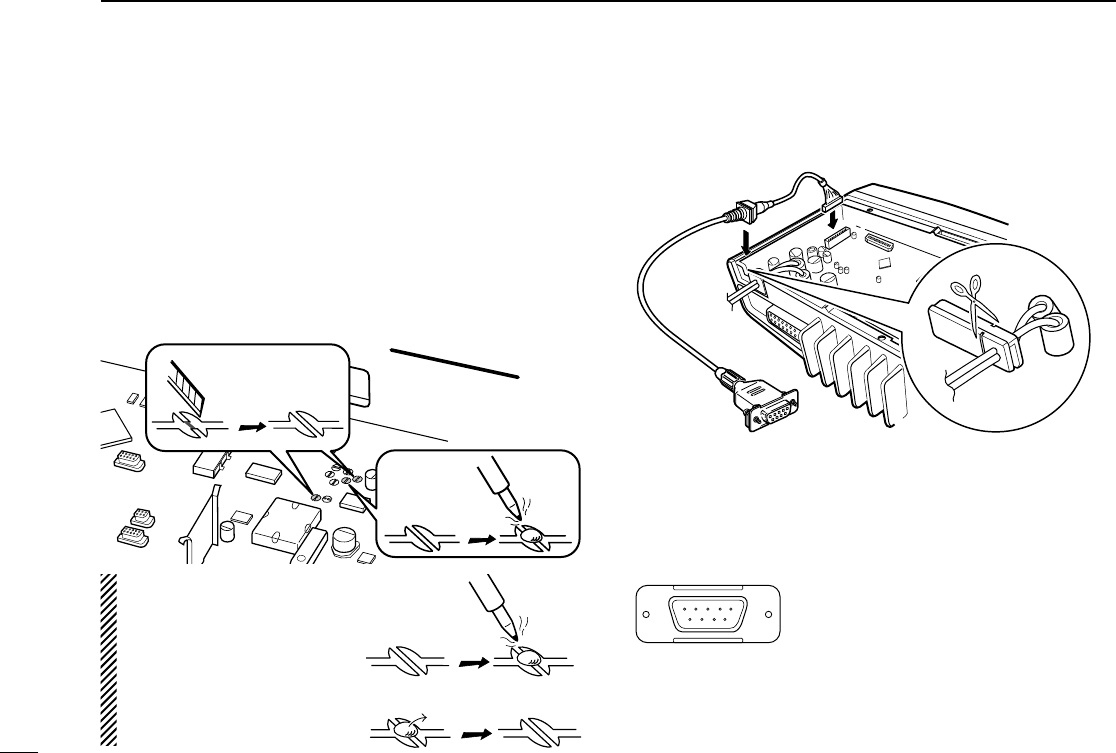
■Optional UT-109 or UT-110
installation
qTurn the power OFF, then disconnect the DC power cable.
wUnscrew the 4 cover screws, then remove the bottom cover.
eCut the pattern on the PCB at the TX mic circuit (MIC) and
RX AF circuit (AF OUT), then solder CP37 as shown below.
rInstall the scrambler unit as described in the installation of
optional UT-111 installation on p. 27
tReplace the bottom cover and screws.
■Optional OPC-617 installation
Install the OPC-617 as shown below.
q
Dimmer cont. IN or
IGSW cont. IN
wAF OUT
eDet. AF OUT
rMod. IN
tPTT control IN or
yHorn drive cont. OUT
uAF GND
iDet. AF GND
oMod. GND
OPTIONAL CABLE PIN ASSIGNMENT
t r e w q
o i u yFTSW control IN
OPC-617
Cut off the bushing as in the
illustration, when you install
the optional OPC-617.
FRONTFRONT
MIC and AF OUT
CP37
Un-solder
Re-solder
Remove
NOTE: When uninstalling
the unit
Be sure to re-solder the
disconnected points and
un-solder the connected
points as above when you
remove the unit. Otherwise
no TX modulation or AF
output is available.
!IC-F1721D.qxd 04.9.2 5:58 PM Page 28 (1,1)

29
4
CONNECTION AND MAINTENANCE
■Antenna
A key element in the performance of any communication sys-
tem is an antenna. Contact your dealer about antennas and
the best places to mount them.
■Fuse replacement
A fuse is installed in the supplied DC power cable. If a fuse
blows or the transceiver stops functioning, track down the
source of the problem if possible, and replace the damaged
fuse with a new rated one.
❑Fuse rating: 20 A
■Cleaning
If the transceiver becomes dusty or dirty, wipe it clean with a
soft, dry cloth.
AVOID the use of solvents such as benzene or
alcohol, as they may damage the transceiver sur-
faces.
■Options
• RMK-2
SEPARATION KIT
+
OPC-607/OPC-608/OPC-609
SEPARATION CABLE
Allows you to install the transceiver main unit separately
from the front panel for operating convenience.
• SP-5/SP-22
EXTERNAL SPEAKER
Input impedance : 4 Ω
Max. input power : 5 W
SP-5 : Large speaker for good audio quality.
SP-22 : Compact and easy-to-install. The same as supplied
with the transceiver depending on version.
• HM-100TN/HM-100N/HM-148
HAND MICROPHONE
HM-100TN : Hand microphone with a DTMF keypad.
HM-148 : The same as supplied with the transceiver
depending on version.
• SM-25
DESKTOP MICROPHONE
• UT-109 (#02)/UT-110 (#02)
SCRAMBLER UNITS
Non-rolling type (UT-109)/Rolling type (UT-110) voice
scrambler unit provides higher communication security.
• UT-111
TRUNKING BOARD
Provides trunking operation.
• OPC-617
ACC CABLE
Allows you to connect to an external terminal.
!IC-F1721D.qxd 04.9.2 5:58 PM Page 29 (1,1)
30
5SAFETY TRAINING INFORMATION
Your Icom radio generates RF electromagnetic
energy during transmit mode. This radio is
designed for and classified as “Occupational Use
Only”, meaning it must be used only during the
course of employment by individuals aware of the
hazards, and the ways to minimize such hazards.
This radio is NOT intended for use by the “General
Population” in an uncontrolled environment.
• For compliance with FCC and Industry Canada RF Exposure
Requirements, the transmitter antenna installation shall comply with
the following two conditions:
1. The transmitter antenna gain shall not exceed 0 dBi.
2. IC-F1721/IC-F1721D/IC-F1821/IC-F1821D:
The antenna is required to be located outside of a vehicle and
kept at a distance of 1 meter or more between the transmitting
antenna of this device and any persons during operation. For
small vehicle as worst case, the antenna shall be located on the
roof top at any place on the centre line along the vehicle in order
to achieve 1 meter separation distance. In order to ensure this
distance is met, the installation of the antenna must be mounted
at least 1 meter away from the nearest edge of the vehicle in
order to protect against exposure to bystanders.
3. IC-F2721/IC-F2721D/IC-F2821/IC-F2821D:
The antenna is required to be located outside of a vehicle and
kept at a distance of 79 centimeters or more between the trans-
mitting antenna of this device and any persons during operation.
For small vehicle as worst case, the antenna shall be located on
the roof top at any place on the centre line along the vehicle in
order to achieve 79 centimeters separation distance. In order to
ensure this distance is met, the installation of the antenna must
be mounted at least 79 centimeters away from the nearest edge
of the vehicle in order to protect against exposure to bystanders.
To ensure that your exposure to RF electromag-
netic energy is within the FCC allowable limits
for occupational use, always adhere to the fol-
lowing guidelines:
•DO NOT operate the radio without a proper antenna attached, as
this may damage the radio and may also cause you to exceed FCC
RF exposure limits. A proper antenna is the antenna supplied with
this radio by the manufacturer or an antenna specifically authorized
by the manufacturer for use with this radio.
•DO NOT transmit for more than 50% of total radio use time (“50%
duty cycle”). Transmitting more than 50% of the time can cause FCC
RF exposure compliance requirements to be exceeded. The radio
is transmitting when the “TX indicator” lights red. You can cause the
radio to transmit by pressing the “PTT” switch.
Electromagnetic Interference/Compatibility
During transmissions, your Icom radio generates RF energy that can
possibly cause interference with other devices or systems. To avoid
such interference, turn off the radio in areas where signs are posted
to do so. DO NOT operate the transmitter in areas that are sensitive
to electromagnetic radiation such as hospitals, aircraft, and blasting
sites.
WARNING
CAUTION
!IC-F1721D.qxd 04.9.2 5:58 PM Page 30 (1,1)

1-1-32 Kamiminami, Hirano-ku, Osaka 547-0003, Japan
A-6406H-1EX
Printed in Japan
© 2004 Icom Inc.
!IC-F1721D.qxd 04.9.2 5:58 PM Page Z (1,1)