ICOM orporated 279100 VHF Air Band Transceiver User Manual
ICOM Incorporated VHF Air Band Transceiver
Contents
- 1. Users Manual
- 2. User Manual
- 3. User manual
User manual
INSTRUCTION MANUAL
iA6
iA24
VHF AIR BAND TRANSCEIVER
This device complies with Part 15 of the FCC
Rules. Operation is subject to the condition
that this device does not cause harmful inter-
ference.
IC-A24 IC-A6
i
FOREWORD
Thank you for purchasing this Icom product. The IC-A24/A6
VHF AIR BAND TRANSCEIVER is designed and built with
Icom’s state of the art technology and craftsmanship. With
proper care this product should provide you with years of
trouble-free operation.
IMPORTANT
READ ALL INSTRUCTIONS carefully and completely
before using the transceiver.
SAVE THIS INSTRUCTION MANUAL— This in-
struction manual contains important operating instructions
for the IC-A24/A6.
EXPLICIT DEFINITIONS
The explicit definitions below apply to this instruction man-
ual.
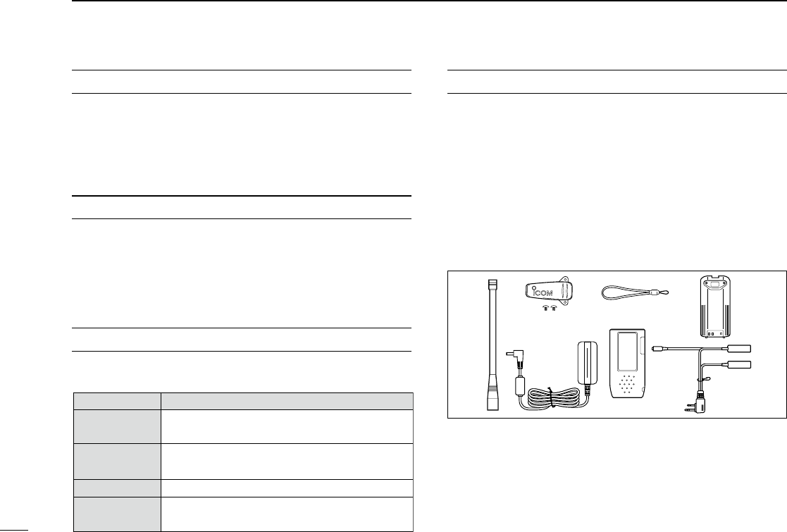
SUPPLIED ACCESSORIES
Accessories included with the transceiver: Qty.
q Antenna .......................................................................... 1
w Belt clip .......................................................................... 1
e Handstrap ...................................................................... 1
r Battery pack* or battery case .......................................... 1
t Wall charger* .................................................................. 1
y Carrying case* ............................................................... 1
u Headset adapter* ........................................................... 1
* Not supplied, or the shape may be different, depending on the
version.
WORD DEFINITION
RWARNING!
CAUTION
NOTE
Personal injury, fire hazard or electric shock
may occur.
RDANGER! Personal death, serious injury or an explo-
sion may occur.
If disregarded, inconvenience only. No
risk
of personal injury, fire or electric shock.
Equipment damage may occur.
qw e
t
r
y
u

ii
R DANGER! NEVER short the terminals of the battery pack.
Also, current may flow into nearby metal objects, such as a necklace,
etc. Therefore, be careful when carrying with, or placing near metal
objects, carrying in handbags, etc.
R DANGER! Use and charge only specified Icom battery packs
with Icom radios or Icom chargers. Only Icom battery packs are
tested and approved for use with Icom radios or charged with Icom
chargers. Using third-party or counterfeit battery packs or chargers
may cause smoke, fire, or cause the battery to burst.
R WARNING! NEVER hold the transceiver so that the antenna
is very close to, or touching exposed parts of the body, especially the
face or eyes, while transmitting. The transceiver will perform best if
the microphone is 5 to 10 cm (2
to 4 inches
) away from the lips and
the transceiver is vertical.
R WARNING! NEVER operate the transceiver with a headset
or other audio accessories at high volume levels. Hearing experts
advise against continuous high volume operation. If you experience a
ringing in your ears, reduce the volume level or discontinue use.
CAUTION: NEVER connect the transceiver to an AC outlet or
to a power source of more than 11.5 V DC. Such a connection will
damage the transceiver.
CAUTION: NEVER connect the transceiver to a power source
that is DC fused at more than 5 A. Accidental reverse connection will
be protected by this fuse, higher fuse values will not give any protec-
tion against such accidents and the transceiver will be ruined.
DO NOT allow children to play with any radio equipment containing
a transmitter.
DO NOT operate the transceiver near unshielded electrical blast-
ing caps or in an explosive atmosphere.
DO NOT use or place the transceiver in direct sunlight or in areas
with temperatures below –10°C (+14°F) or above +60°C (+140°F).
Even when the transceiver power is OFF, a slight current still flows
in the circuits. Remove the battery pack or case from the transceiver
when not using it for a long time. Otherwise, the battery pack or in-
stalled Alkaline cell batteries will become exhausted.
Icom, Icom Inc. and Icom logo are registered trademarks of Icom Incorporated
(Japan) in Japan, the United States, the United Kingdom, Germany, France,
Spain, Russia, Australia, New Zealand, and/or other countries.
FCC caution: Changes or modifications to this transceiver, not
expressly approved by Icom Inc., could void your authority to op-
erate this transceiver under FCC regulations. (U.S.A. only)
PRECAUTION
MISE EN GARDE: Utilisation de 8.33 kHz Espacement des ca-
naux de cette radio est strictement interdite et ne doit pas être
utilisé au Canada.
CAUTION: Use of 8.33 kHz Channel Spacing of this radio is
strictly prohibited and shall not be used in Canada.

iii
TABLE OF CONTENTS
FOREWORD .....................................................................................i
IMPORTANT ...................................................................................... i
EXPLICIT DEFINITIONS ................................................................... i
SUPPLIED ACCESSORIES .............................................................. i
PRECAUTION .................................................................................. ii
TABLE OF CONTENTS ................................................................... iii
1 ACCESSORY ATTACHMENT ....................................................1
2 PANEL DESCRIPTION ..........................................................2–7
■Panel description ....................................................................2
■Function display ......................................................................6
3 BASIC OPERATION .............................................................8–11
■Setting a frequency ................................................................. 8
■Selecting a weather channel (U.S.A. version only) .................8
■Receiving ................................................................................9
■ANL function ...........................................................................9
■Channel spacing setting ..........................................................9
■Setting a squelch level ............................................................9
■ Transmitting .............................................................................9
■Low battery indicator .............................................................10
■Recall function ......................................................................10
■Setting weather alert function ...............................................11
■ Accessing the 121.5 MHz emergency frequency ..................11
■Lock function ......................................................................... 11
■Side tone function .................................................................11
■Setting beep tone .................................................................. 11
4 MEMORY OPERATION ......................................................12–15
■Memory channel selection .................................................... 12
■ Transferring memory contents ..............................................12
■ Programming a memory channel ..........................................13
■Memory names ..................................................................... 14
■Clearing the memory contents .............................................. 14
5 SCAN OPERATION ............................................................16–17
■Scan types ............................................................................16
■COM band scan ....................................................................16
■Memory scan ........................................................................16
■ Weather channel scan (U.S.A. version only) ......................... 17
■“TAG” channel setting ............................................................17
6 VOR NAVIGATION (IC-A24 ONLY) .................................... 18–24
■VOR indicators ...................................................................... 18
■VOR functions ....................................................................... 19
■Flying to a VOR station .........................................................20
■Entering a desired course ..................................................... 22
■Crosschecking position .........................................................22
■ Duplex operation (U.S.A. version only) .................................24
7 CLONING .................................................................................25
8 BATTERY PACKS ..............................................................26–29
■Battery cautions .................................................................... 26
■Battery charging ....................................................................26
■Optional battery case ............................................................ 27
■Optional battery chargers .....................................................28
9 SPECIFICATIONS .............................................................. 30–31
10 OPTIONS ..................................................................................32
11 OPTIONAL HEADSET CONNECTION .................................... 33
12 SAFETY TRAINING INFORMATION..................................34–35
13 FOR CLASS A UNINTENTIONAL RADIATORS ..................... 36
14 TROUBLESHOOTING .............................................................37
INDEX .......................................................................................38–39
1
1
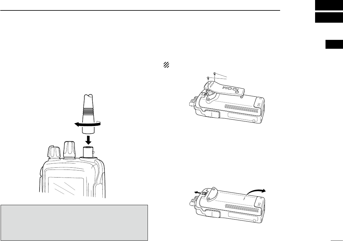
ACCESSORY ATTACHMENT
ïAntenna
CAUTION: DO NOT transmit without an antenna. Other-
wise the transceiver may be damaged.
Insert the supplied antenna into the antenna connector and
screw down the antenna as shown below.
ïBelt clip
Conveniently attaches to your belt.
Attach the belt clip with the supplied screws as below.
NOTE: Use the supplied screws only.
ïBattery pack replacement
Before replacing the battery pack, push [PWR] for 2 seconds
to turn the power OFF.
Slide the battery release button forward, then pull the battery
pack upward with the transceiver facing away from you.
Supplied screws
NOTE: About water resistant construction
The water resistant construction provides reliable opera-
tion in wet conditions.
• Equivalent to IPX4 of corresponding international stand-
ard IEC 60529 (2001).
2
3
1
4
5
6
7
9
10
8
12
13
11
14
2
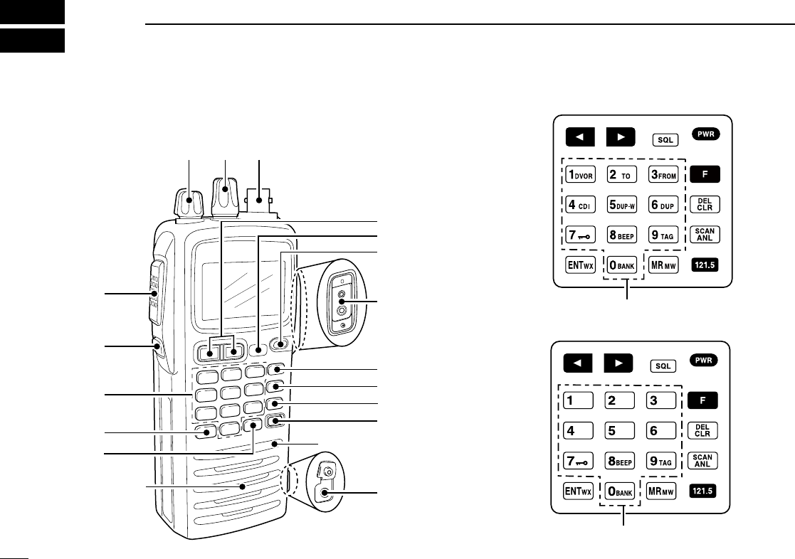
2PANEL DESCRIPTION
■Panel description
ert
u
y
i
o
Microphone
Speaker
!6
!5
!7
q
w
!1
!0
!2
!3
!4
WX-ALERT
IC-A24
!7
WX-ALERT
!7
IC-A6
3
2
PANEL DESCRIPTION
q BACKLIGHT SWITCH [LIGHT]
Turns the backlight for display and keypad ON or OFF.
w PTT SWITCH [PTT] (p. 9)
Hold down to transmit; release to receive.
• “ ” appears on the function display while transmitting.
e VOLUME [VOL] (p. 9)
Adjusts the audio level.
r TUNING DIAL [DIAL] (pp. 8–12)
➥ Rotate [DIAL] to select the desired frequency, WX
channel number, BANK number and memory channel.
➥ Rotate [DIAL] to set the squelch level and beep tone
level.
t ANTENNA CONNECTOR [ANT] (p. 1)
Connect the supplied antenna here.
y RECALL CHANNEL UP/DOWN KEYS [Ω]/[≈] (p. 10)
➥ Push to enter the recall function mode.
➥ Push to call the stored frequency in the recall
mode.
➥ Push , then push [Ω]/[≈] to replace stored
recall frequencies to back or front.
u SQUELCH KEY [SQL•WX-ALERT] (p. 9)
➥ Push [SQL•WX-ALERT], then rotate [DIAL] to
select the squelch level.
• 24 squelch levels and squelch open (0) are available.
➥ Push , then push [SQL•WX-ALERT] to turn
the WX-alert function ON or OFF.
i POWER SWITCH [PWR] (pp. 9, 25)
➥ Hold down for 2 seconds to turn the power ON
or OFF.
➥ While holding down [MR•MW], push [PWR] to
enter the cloning function mode.
o EXTERNAL SPEAKER AND MICROPHONE JACKS
[MIC/SP] (p. 33)
If desired, connect an OPC-499 HEADSET ADAPTER and
headset.
!0 FUNCTION KEY [ ]
Push to call up the function indicator, “ ”, then
push another key to access its secondary func-
tion.
• “ ” appears for 3 seconds after is pushed; at this
time pushing again cancels the indication.
NOTE: In general, “ ” disappears when an-
other key is pushed to activate a secondary
function. However, some keys which have
more than one secondary function, (such as
[DUP]), do not cancel “ ”. In this case, “ ”
automatically disappears after 3 seconds
2
3
1
4
5
6
7
9
10
8
12
13
11
14
4
2PANEL DESCRIPTION
!1 CLEAR KEY [CLR•DEL] (pp. 8–17)
➥ Push to return to the frequency mode, when
memory channel, WX channel, 121.5 MHz,
squelch level setting or beep tone setting is se-
lected.
➥ Push , then hold down [CLR•DEL] to delete
a recall frequency data.
➥ Push to clear the entered comment of memory
name while programming.
➥ Push to stop the scan function to return to the
frequency mode while the scan function is op-
erating.
!2 ANL KEY [ANL•SCAN] (pp. 9, 16, 17)
➥ Push to turn the ANL function ON or OFF.
➥ Push , then push [ANL•SCAN] to start the
scan function.
!3 EMERGENCY KEY [121.5 MHz] (p. 11)
Push for 2 seconds to select the 121.5 MHz emer-
gency frequency.
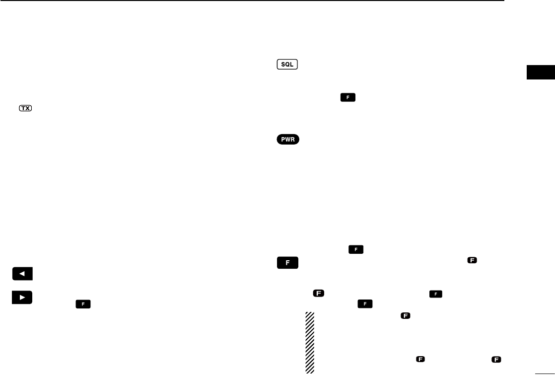
!4 DC POWER JACK
Connect the AC adapter or optional cable, to charge the
battery pack or to operate by external power. (see right il-
lustration)
!5 MEMORY MODE KEY [MR•MW] (pp. 12–15)
➥ Push to select the memory channel mode.
➥ Push , then push [MR•MW] to program the
contents into the memory channels.
!6 ENTER KEY [ENT•WX] (pp. 8, 14)
➥ Push to store the numeral input. Enters con-
secutive zero digits. (p. 8)
➥ Push , then push [ENT•WX] to enter the
weather channel selection mode (U.S.A. ver-
sion only). (p. 8)
➥ Push to program the memory name. (p. 14)
NOTE: Some functions may not be available depending on
versions. Ask your authorized dealer for details.
Wall charger
To [DC 11V]
IC-A24/A6
CP-20 (for 11 24 V)
(optional)
To the cigarette
lighter socket
To AC outlet
The shape may
differ depending
on the version.
• DC POWER CONNECTION
R WARNING!
• NEVER modify the CP-20. A modification
could cause a fire or electrocution.
• NEVER cut or fray the CP-20’s power cable
when disconnecting/connecting the CP-20
from/to the cigarette lighter socket.
5
2
PANEL DESCRIPTION
!7 DIGIT KEYS
➥ Input the specified digit during frequency input, mem-
ory channel selection, etc.
➥ In addition, each key has one or more secondary func-
tions after pushing as follows:
Push , then push [0•BANK], and rotate [DIAL]
to select the memory BANK number during mem-
ory mode operation. (p. 12)
Push , then push [1•DVOR] to select the DVOR
display from the CDI display in the NAV band.
(p. 19)*1
➥ Push , then push [2•TO] to change the
course indicator characteristics to a “TO” flag in
the DVOR display in the NAV band. (p. 19)*1
➥ Corrects the deviation while using the “TO”
flag.*1
➥ Push , then push [3•FROM] to change the
course indicator characteristics to a “FROM”
flag in the DVOR display in the NAV band.
(p. 19)*1
➥ Corrects the deviation while using the “FROM”
flag.*1
Push , then push [4•CDI] to select the CDI dis-
play from the CDI display in the NAV band.
(p. 19)*1
Push , then push [5•DUP-W] to set the duplex
frequency in the NAV band for U.S.A. version only.
(p. 24)*1
Push , then push [6•DUP] to turn the duplex
function ON and OFF in the NAV band for U.S.A.
version only. (p. 24)*1
Push , then push [7• ] to turn the key lock
function ON and OFF. (p. 11)
Push , then push [8•BEEP] to turn the beep
tone setting mode ON. (p. 11)
• Adjustable level; 0 to 9
Push , then push [9•TAG] to set the displayed
memory or weather channel as a “TAG” channel.
(p. 17)
*1 These functions are available on the IC-A24 only.
2
3
1
4
5
6
7
9
10
8
12
13
11
14
6
2PANEL DESCRIPTION
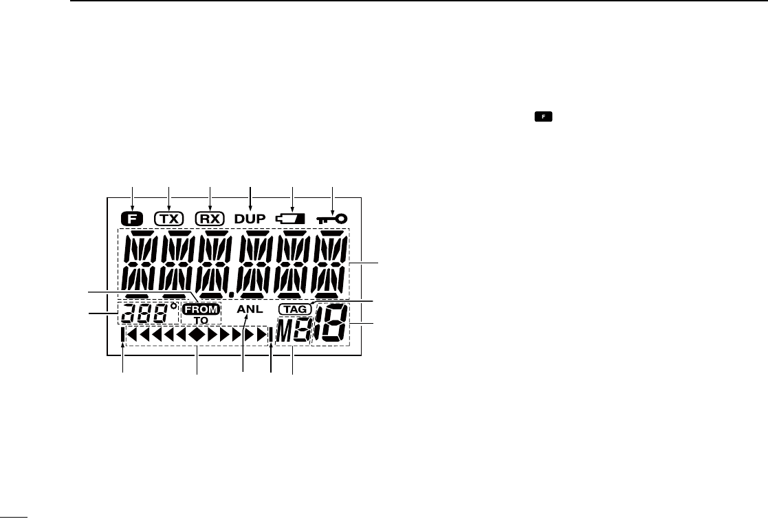
■Function display
q FUNCTION INDICATOR (p. 3)
Appears when is pushed.
w TX INDICATOR (p. 9)
Appears while transmitting.
e RX INDICATOR (p. 9)
Appears when receiving a signal, or when the squelch
opens.
r DUPLEX INDICATOR (IC-A24 only) (p. 24)
➥ “DUP” appears when the duplex function is activated in
the NAV mode.
➥ “DUP” blinks while setting the duplex frequency.
t LOW BATTERY INDICATOR (p. 10)
➥ Appears when the battery is nearing exhaustion. The
attached battery pack requires recharging.
➥ Appears and flashes when battery replacement is nec-
essary.
y LOCK INDICATOR (p. 11)
Appears while the lock function is in use.
i
qw erty
o
!0
!1!1 !2!3
!4
u
!5

7
2
PANEL DESCRIPTION
u FREQUENCY DISPLAY (pp. 8, 14)
➥ Shows the operating frequency.
➥ Shows the channel name when the memory name
function is selected.
[NOTE]
When you set the IC-A24/A6’s channel spacing to
8.33 kHz, the displayed frequency is different from the ac-
tual operating frequency.
See “VFO CHANNEL ID LIST” for details. (p. 31)
i TAG CHANNEL INDICATOR (p. 17)
“” appears when the selected memory channel is set
as a TAG channel.
o MEMORY CHANNEL INDICATOR (pp. 12–15)
Shows the selected memory channel number.
!0 MEMORY BANK NUMBER INDICATOR (p. 12)
Shows the selected memory bank number.
!1 OVERFLOW INDICATOR (IC-A24 only) (pp. 18–22)
Appears when the deviation between the desired course
and flying course is over 10 degrees.
!2 ANL INDICATOR (p. 9)
Appears while the ANL (Automatic Noise Limiter) function
is in use.
!3 COURSE DEVIATION NEEDLES (IC-A24 only)
(pp. 18–22)
Indicates every 2 degree deviation between the desired
course and your actual flying course every 2 degrees.
!4 COURSE INDICATORS (IC-A24 only) (p. 19)
➥ Indicates where your aircraft is located on a VOR radial
in the DVOR mode.
➥ Indicates where your desired course is located on a
VOR radial in the CDI mode.
!5 TO-FROM INDICATOR (IC-A24 only) (p. 19)
Indicates whether the VOR navigation information is
based on a course leading to the VOR station or leading
away from the VOR station.
2
3
1
4
5
6
7
9
10
8
12
13
11
14
8
■Setting a frequency
ïUsing keypad
q Push [PWR] for 2 seconds to turn power ON, then push
[CLR•DEL] to select the frequency mode when memory
CH number or WX CH number appears on the function
display.
w Push 6 appropriate digit keys to input the frequency.
• When operating on only 25 kHz channel spacing, push
5 appropriate digit keys to input the frequency.
• Push [ENT•WX] to enter remaining zero digits.
• When a wrong digit is input, push [CLR•DEL] to clear,
then repeat step w again.
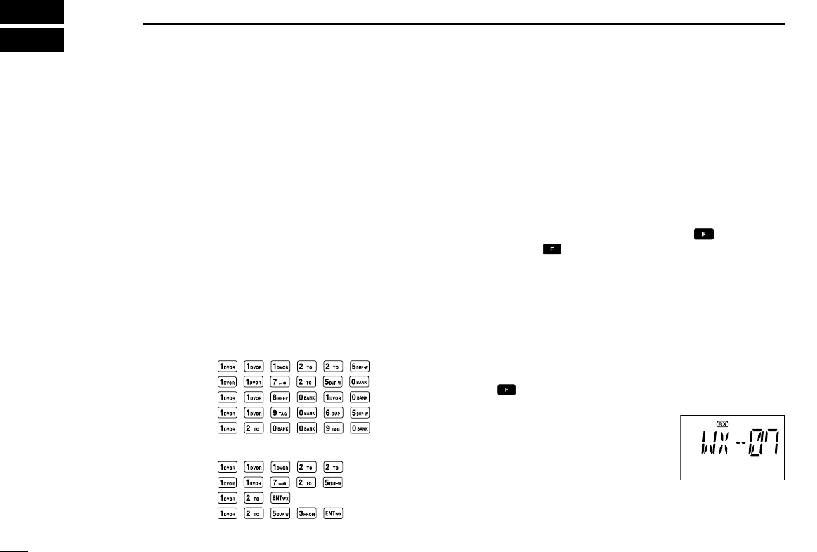
[EXAMPLE]
When operating on either only 8.33 kHz channel spacing
or 8.33 kHz/25 kHz channel spacing.
• 111.225 MHz: Push
• 117.250 MHz: Push
• 118.0083 MHz: Push
• 119.0667 MHz: Push
• 120.0917 MHz: Push
When operating on only 25 kHz channel spacing.
• 111.225 MHz: Push
• 117.250 MHz: Push
• 120.000 MHz: Push
• 125.300 MHz: Push
ïUsing the tuning dial
q Push [PWR] for 2 seconds to turn power ON, then push
[CLR•DEL] to select the frequency mode when memory
CH number or WX CH number appears on the function
display.
w Rotate [DIAL] to set the desired frequency.
• To select the 1 MHz tuning step, push , then rotate
[DIAL]. Push again to return to the normal tuning.
■ Selecting a weather channel
(U.S.A. version only)
The U.S.A. version has VHF marine WX (weather) channel
receiving capability for flight planning.
q Push , then push [ENT•WX] to select WX channel
mode.
• “WX--” and the previously selected
channel number appears.
w Rotate [DIAL] to select the de-
sired WX channel.
e Push [CLR•DEL] to exit the WX
channel mode and return to fre-
quency mode.
3BASIC OPERATION
9
3
BASIC OPERATION
■Receiving
q Push [PWR] for 2 seconds to turn the power ON.
w Push [SQL•WX-ALERT], then rotate [DIAL] counterclock-
wise to select the squelch level 0.
e Rotate [VOL] to adjust the audio level.
r Push [SQL•WX-ALERT], then rotate [DIAL] clockwise until
the noise is muted.
• “ ” indicator disappears.
t Set the desired frequency using [DIAL] or keypad.
y When a signal is received on the set frequency:
• “ ” indicator appears.
• Squelch opens and audio is emitted from the speaker.
When [SQL] setting is too “tight,” squelch may not open for
weak signals. To receive weaker signals, loosen the squelch.
■ANL function
While receiving, the ANL (Automatic Noise Limiter) function
reduces noise components such as those that are caused
by engine ignition systems while receiving.
• Push [ANL•SCAN] to turn the ANL function ON/OFF.
“ ” appears on the display while the ANL function is ON.
■Channel spacing setting
If you set the channel spacing to only 8.33 kHz or only 25
kHz, the optional CS-A24 (#02) cloning software and the
optional cloning cable are required.
See “Cloning using PC” (p. 25) for details.
■Setting a squelch level
The transceiver has a noise squelch circuit to mute unde-
sired noise while receiving no signal.
q Push [SQL•WX-ALERT], then rotate [DIAL] to select the
squelch level.
• ‘SQL--0’ is open squelch and ‘SQL--24’ is tight squelch.
• “ ” appears while the squelch is open.
w Push [SQL•WX-ALERT] or [CLR•DEL] to exit the squelch
set mode.
■ Transmitting
q Set the desired frequency in COM band using [DIAL] or
keypad.
• COM band frequency range: 118.000–136.9917 MHz
w Hold down [PTT] to transmit.
• “ ” indicator appears.
e Speak into the microphone at a normal voice level.
• DO NOT hold the transceiver too close to your mouth or speak
too loudly. This may distort the signal.
r Release [PTT] to return to receive.
CAUTION: Transmitting without an antenna may damage
the transceiver.
NOTE: To prevent interference, listen on the frequency
before transmitting. If the frequency is busy, wait until the
channel is clear.
2
3
1
4
5
6
7
9
10
8
12
13
11
14
10
3BASIC OPERATION
■Low battery indicator
Low battery indicator appears
when the battery power has de-
creased to a specified level. The
attached battery pack requires
recharging.
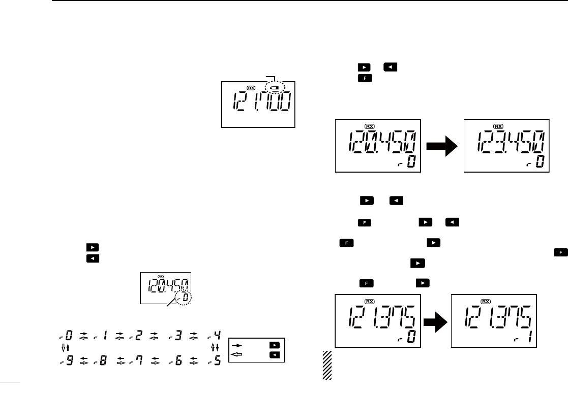
■Recall function
The recall function stores the last 10 frequencies used.
The function stores frequencies when the frequency is pro-
grammed and transmitted on (except memory, weather and
emergency channels).
ïRecalling the stored frequencies
➥ Push to recall the 1st stored frequency.
➥ Push to recall the 10th stored frequency.
ïDeletes the stored recall channel
q Push or to select the channel to be deleted.
w Push , then push [CLR•DEL] for 2 seconds to delete it.
• (e.g.) When the “r0” recall channel which is stored 120.450 MHz
is deleted, the “r1” recall channel which is stored 123.450 MHz
move up to “r0”.
ïReplaces the stored recall channel
q Push or to select the recall channel to be re-
placed.
w Push , then push or to replace it.
• Replaces the selected channel into the previous channel when
is pushed and then is pushed.
• Replaces the selected channel into the next channel when
is pushed and then is pushed.
• (e.g.) To replace “r0” which is stored as 121.375 MHz into “r1”,
push , then push .
NOTE: When the number of stored frequencies reaches
10, channels are automatically deleted as needed, in the
order they were entered, beginning the oldest.
Low battery indicator
Recall number appears.
: Push
: Push
• Recall number rotation
11
3
BASIC OPERATION
2
3
1
4
5
6
7
9
10
8
12
13
11
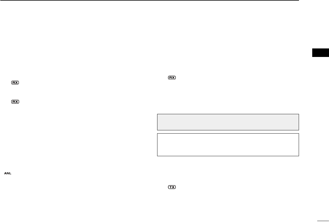
■Setting weather alert function
An NOAA broadcast station transmits a weather alert tone
before any important weather announcements. When the
weather alert function is turned ON, the transceiver detects
the alert, and sounds a beep tone until the transceiver is op-
erated. The previously selected (used) weather channel is
checked any time during standby, or while scanning.
•
To turn ON the weather alert function, push , then hold
down [SQL•WX-ALERT] until “ ” is displayed.
•
To turn OFF the function, push , then push [SQL•WX-
ALERT]. (“ ” is displayed for 1 second).
■ Accessing the 121.5 MHz
emergency frequency
The IC-A24 and IC-A6 can set to the 121.5 MHz emergency
frequency quickly. This function can be activated even when
the key lock function is in use.
q Push [121.5] for 2 seconds to select the emergency fre-
quency.
w Push [CLR•DEL] to exit the emergency frequency.
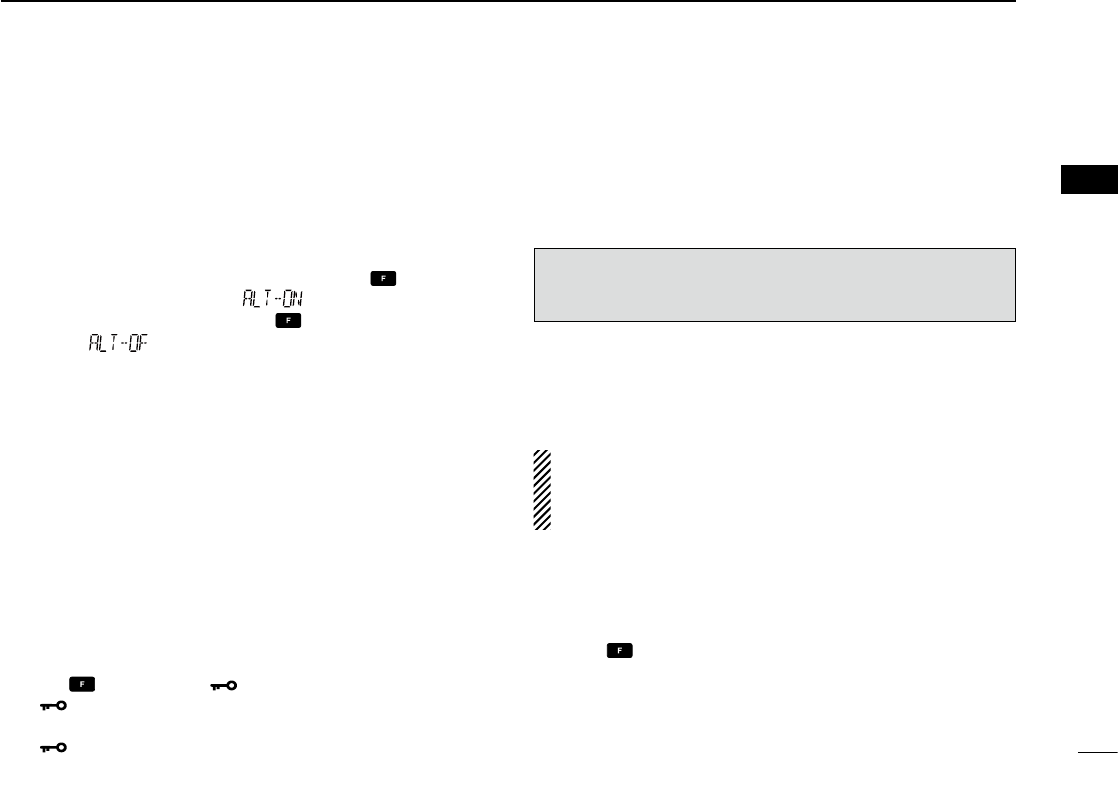
■Lock function
The lock function prevents accidental frequency changes
and accidental function activation.
q Push , then push [7• ] to turn the lock function ON.
• “ ” appears.
w To turn the function OFF, repeat step q above.
• “ ” disappears.
■Side tone function
When using an headset (other manufacture’s products), the
transceiver outputs your transmitted voice to the headset for
monitoring. Connect the optional headset with the trans-
ceiver when using this function (OPC-499 HEADSET
ADAPTER and headset are required) (p. 33).
ïSetting the side tone level
q Push [PTT] to turn the transmit mode ON.
w During transmit mode, rotate [DIAL] to adjust the monitor-
ing level.
• ‘ST--0’ is OFF and ‘ST--10’ is maximum level.
R WARNING! NEVER operate the transceiver with a
headset at high volume levels for long period. A ringing in
your ears may occur. If so, reduce the monitor level or
discontinue use.
■Setting beep tone
If desired, the beep tone, which sounds at the push of a
switch, can be set.
q Push , then push [8•BEEP] to enter the beep tone
setting mode.
w Rotate [DIAL] to set the beep level.
• ‘BEP-- 0’ is OFF and ‘BEP-- 9’ is maximum level.
• 2 beeps sound tone to verify set beep tone level.
e Push [CLR•DEL] to exit the beep tone setting mode.
IMPORTANT: Set the monitoring level to ‘ST--0’ when using
an optional HM-234 sPeaKer MicroPHone, otherwise,
your voice will be heard from the speaker during transmitting.
14
12
4MEMORY OPERATION
■Memory channel selection
The transceiver has 200 memory channels for storage of
often-used frequencies, along with 6-character notes.
q Push [MR•MW] to select the memory mode.
• The memory BANK number and memory CH number appears.
Using [DIAL]:
w Push , then push [0•BANK], and rotate [DIAL] to select
the desired memory BANK number. Push and push
[0•BANK] (or push [CLR•DEL]) to exit the BANK selection
mode.
e Rotate [DIAL] to select the desired memory CH number.
• If no memory CH is programmed in the selected BANK, no
memory CH selection is available.
Using the Keypad:
w Push , and push [0•BANK], then push the appropriate
digit key ([0•BANK] to [9•TAG]) to select the desired mem-
ory BANK number, then push and push [0•BANK] (or
push [CLR•DEL]) to exit the BANK-selection mode.
e Push 2 appropriate digit key (00 to 19) to select the de-
sired memory CH number.
• If no memory CH is programmed in the selected BANK, no
memory CH selection is available.
NOTE: Comments appear first when programmed, how-
ever, the transceiver can be programmed by your dealer
to show the operating frequency first. Push [MR•MW] to
display the comment in this case.
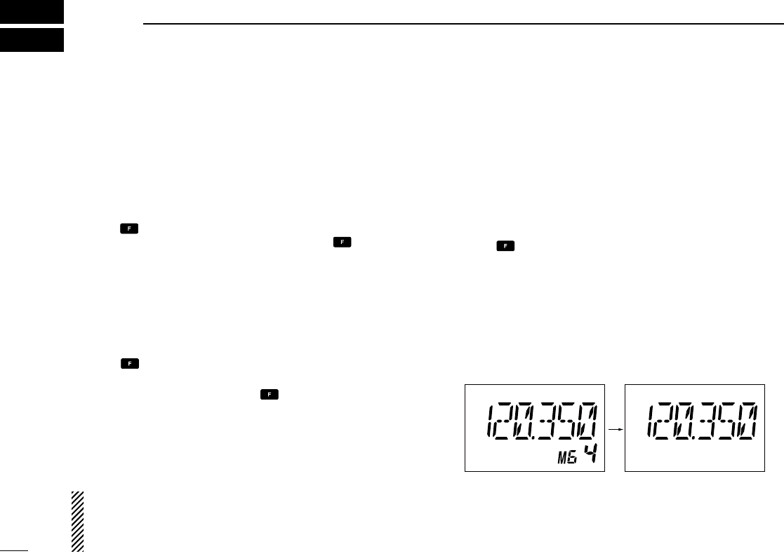
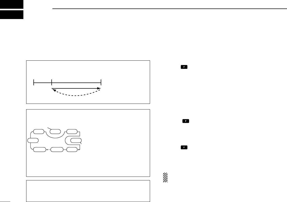
■ Transferring memory contents
This function transfers a memory channel’s contents into the
frequency mode. This is useful when searching for signals
around a memory channel’s frequency.
q Push [MR•MW] to select memory mode.
w Select the desired memory channel to be transferred
using [DIAL] or keypad.
e Push , then push [MR•MW] to transfer the memory
channel’s contents into the frequency mode.
• BANK number and memory CH number disappears as fre-
quency mode is automatically selected and the memory con-
tents are transferred.
Memory mode Frequency mode
13
4
MEMORY OPERATION
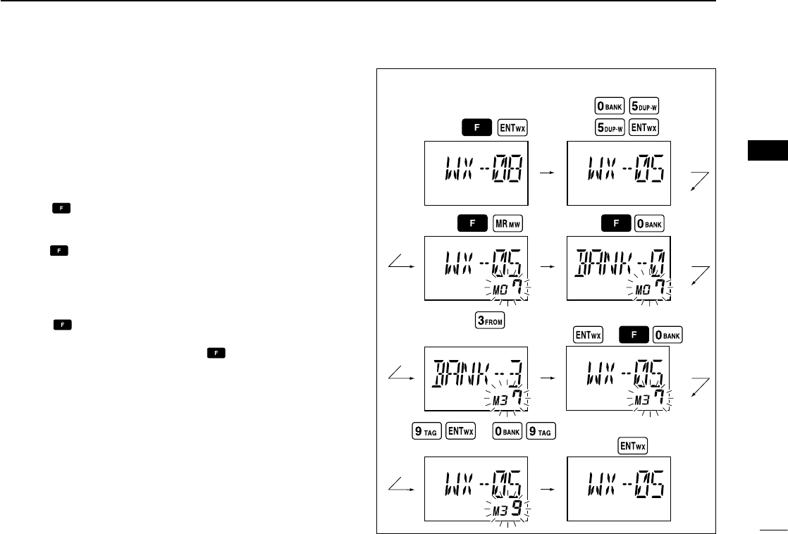
■ Programming a memory channel
The transceiver has 200 (20 CH × 10 BANK) memory chan-
nels for storage of often-used frequencies.
q Push [CLR•DEL] to select the frequency mode, if neces-
sary.
w Select the desired frequency.
• Push , then push [ENT•WX] to select a weather channel.*
• Set the desired frequency or weather channel* using [DIAL] or
keypad.
e Push , then push [MR•MW] to enter the memory writ-
ing mode.
• “M”, Memory BANK and memory channel number are blink.
r Rotate [DIAL] to select the desired memory channel
number.
• Push , then push [0•BANK], and rotate [DIAL] to select the
BANK number if desired.
• Push [CLR•DEL], [ENT•WX] or push then push [0•BANK] to
exit the BANK selection mode.
t Push [ENT•WX] to program the information into the chan-
nel and return to the frequency mode.
*Weather channel: U.S.A. version only.
(or rotate [DIAL])
(or rotate [DIAL])
Push
Push
Push
Push
Push
or
or
Push
Push
Push
or
• EXAMPLE: Programming WX-05* into memory BANK 3/
memory channel 9. 2
3
1
4
5
6
7
9
10
8
12
13
11
14
14
4MEMORY OPERATION
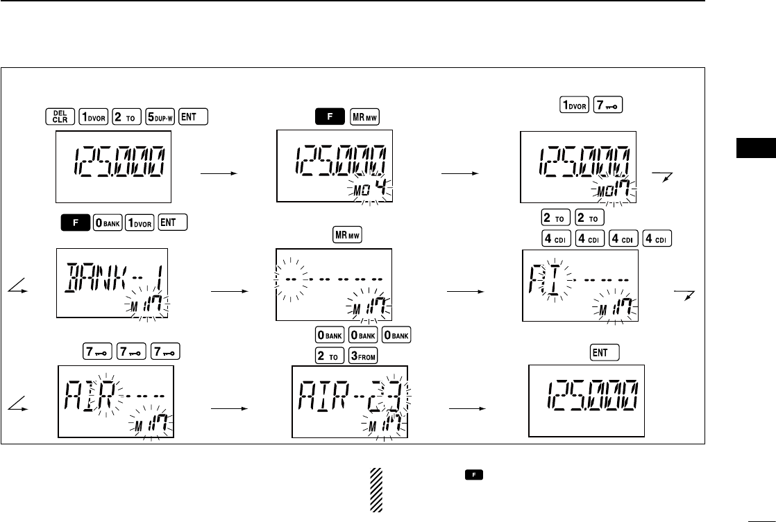
■Memory names
ïProgramming memory names
The memory channel can display a 6-character name in-
stead of the programmed frequency.
q In the frequency mode, rotate [DIAL] to select the desired
frequency in the frequency mode.
w Push , then push [MR•MW] to program the contents
into the selected memory channel.
e Rotate [DIAL] to select the desired memory channel to be
programmed.
• Push , then push [0•BANK], and rotate [DIAL] to select the
BANK number, if desired. Push [CLR•DEL] to exit the BANK se-
lection mode.
r Push [MR•MW] to enter the memory name programming
mode.
• “-- -- -- -- -- -- ” appears on the display.
t Push the appropriate digit key several times to select the
desired character, as listed to the right.
• To erase a character, overwrite with a space (displayed as _).
• To move the cursor forwards or backwards, use [DIAL].
y Push [ENT•WX] to program the name.
• The memory name stops flashing.
• When no name is programmed, the display shows the operat-
ing frequency.
• To clear the entered memory names, push [CLR•DEL] before
pushing [ENT•WX].
NOTE: When programming the memory name to the pro-
grammed memory channel do the following.
q Follow the same steps as in “Transferring memory con-
tents” (see p. 12).
w Follow steps w–y in “Programming memory names”
(see left column).
■Clearing the memory contents
Unwanted memory channels can be cleared.
q Select the memory channel to be cleared.
w Push , then hold down [CLR•DEL] for 1 second.
• “-- -- -- -- -- --” appears momentarily, then the next selectable
channel appears.
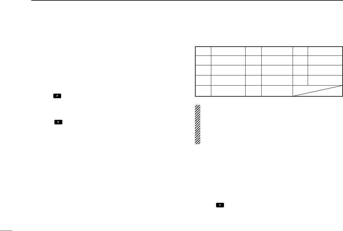
Key Character Key Character Key Character
1 1, Q, Z 2 2, A, B, C 3 3, D, E, F
4 4, G, H, I 5 5, J, K, L 6 6, M, N, O
7 7, P, R, S 8 8, T, U, V 9 9, W, X, Y
ENT Program 0 0, space, -
15
4
MEMORY OPERATION
Push
Push
Push
Push
Push
Push
Push
Push Push
Push Push
(or rotate [DIAL])
(or rotate [DIAL])
• EXAMPLE: Programming 125.000 MHz into memory BANK 1/ memory channel 17 with “AIR-23” as a comment.
NOTE: Push , then push [0•BANK], and then rotate
[DIAL] to select the BANK number, if desired. Push
[CLR•DEL] to exit the BANK selection mode.
2
3
1
4
5
6
7
9
10
8
12
13
11
14
16
5SCAN OPERATION
■Scan types
The U.S.A. version has 3 scan types to suit your needs. The
non-U.S.A. versions have 2 scan types.
■COM band scan
q Push [CLR•DEL] to select the frequency mode.
w Push [SQL•WX-ALERT], then rotate [DIAL] to set the
squelch level to the point where noise is just muted.
e Push , then push [ANL•SCAN] to start the scan.
• When a signal is received, the scan pauses until it disappears.
• To change the scanning direction, rotate [DIAL].
r To stop the scan, push [CLR•DEL].
■Memory scan
q Push [MR•MW] to select the memory mode.
• Push , then push [0•BANK], and rotate [DIAL] to select the
BANK number, if desired. Push [CLR•DEL] to exit the BANK se-
lection mode.
w Push [SQL•WX-ALERT], then rotate [DIAL] to set the
squelch level to the point where noise is just muted.
e Push , then push [ANL•SCAN] to start the scan.
• When a signal is received, the scan pauses until it disappears.
• To change the scanning direction, rotate [DIAL].
r To stop the scan, push [CLR•DEL].
NOTE: Program 2 or more memory channels to start the
memory scan.
WEATHER CHANNEL SCAN
Repeatedly scans all “TAG” weather channels. Weather
channels are available in the U.S.A. version only.
MEMORY SCAN
Repeatedly scans all
selected memory bank’s
“TAG” memory chan-
nels. Used for checking
often-used channels
and bypassing usually
busy channels such as
control-tower frequen-
cies.
COM BAND SCAN
108.000
MHz
Scan
Jump
118.000
MHz
136.9917
MHz
non-TAG
channel
non-TAG channel
Mch 2 Mch 4 Mch 6
Mch 7Mch 1
Mch 8Mch 10Mch 19
Repeatedly scans
all frequencies
over the entire
COM band.
17
5
SCAN OPERATION
■ Weather channel scan
(U.S.A. version only)
q Push , then push [ENT•WX] to select a weather chan-
nel.
w Set the squelch to the point where noise is just muted.
e Push , then push [ANL•SCAN] to start the scan.
• When a signal is received, the scan pauses until it disappears.
• To change the scanning direction, rotate [DIAL].
r To stop the scan, push [CLR•DEL].
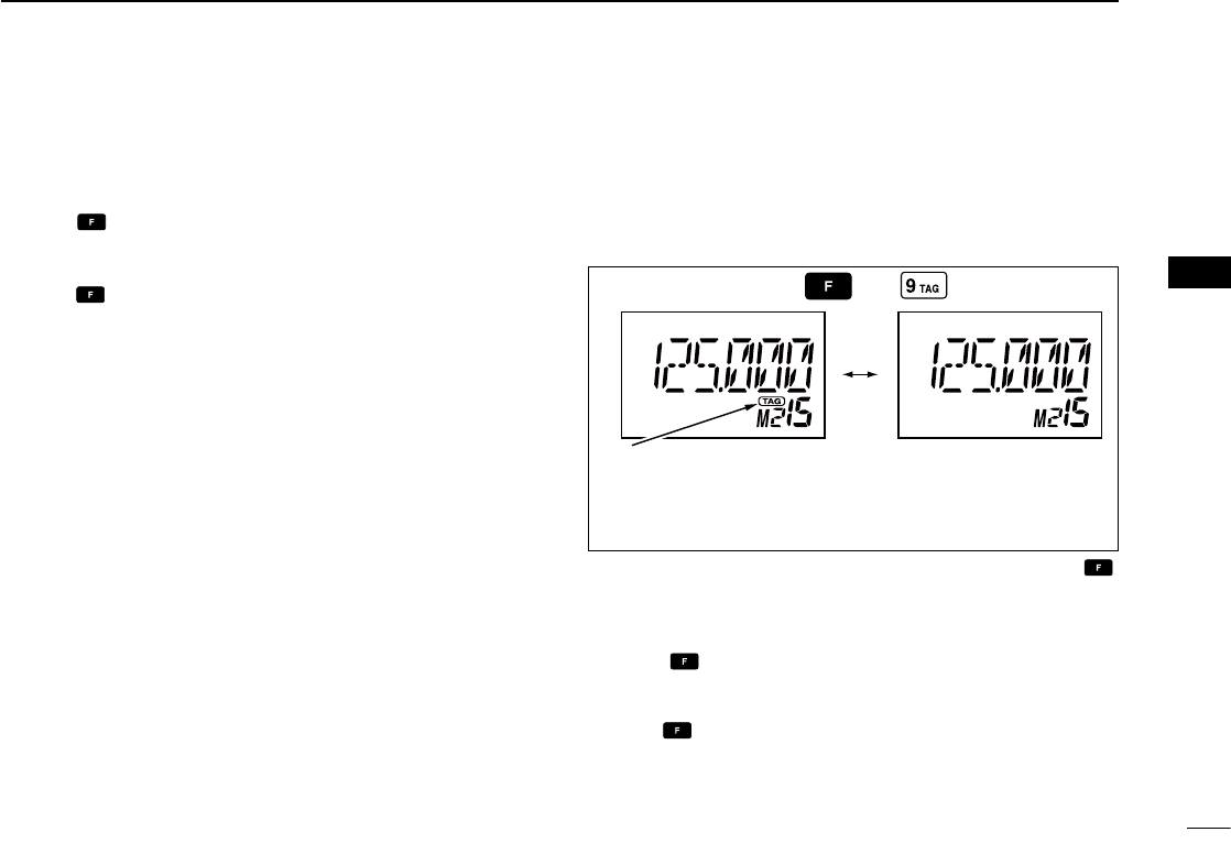
■“TAG” channel setting
Memory and weather channels* can be specified to be
skipped for the memory and weather channel* scans re-
spectively. The “TAG” channel function is only available dur-
ing the scan operation.
q Push [MR•MW] to select the memory mode; or, push ,
then push [ENT•WX] to select a weather channel.*
w Select the desired memory channel to be a “TAG” chan-
nel.
• Push , then push [0•BANK], and rotate [DIAL] to select the
BANK number, if desired. Push [CLR•DEL] to exit the BANK se-
lection mode.
e Push , then push [9•TAG] to set a “TAG.”
• “TAG” appears.
• Non-“TAG” channels are skipped during scan.
r To cancel the “TAG” setting, repeat the above steps.
*Weather channel: U.S.A. version only.
Memory channel 15 is
scanned during memory
scan.
Memory channel 15 is
skipped during scan.
Push then
Appears the “TAG” indicator.
2
3
1
4
5
6
7
9
10
8
12
13
11
14
18
6VOR NAVIGATION (IC-A24 ONLY)
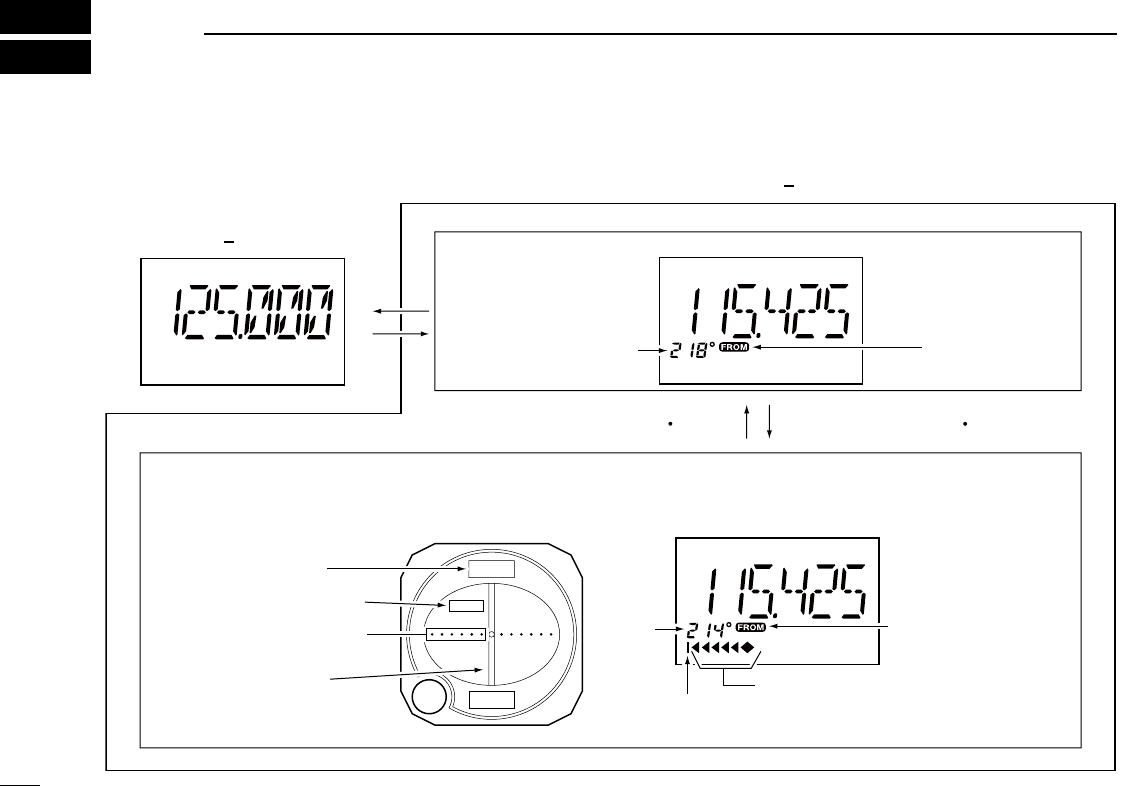
■VOR indicators
214
34
FROM
COM BAND
(118.000 136.9917 MHz)
NAV BAND (108.000 117.975 MHz)
DVOR MODE
Function display of the IC-A24General VOR equipment
To-from flag
indicator
CDI MODE
Course indicator
Course
indicator
Course deviation needles
Overflow indicator
Push [F], then push [4 CDI].Push [F], then push [1 DVOR].
To-from flag indicator
Course indicator
Course deviation
needle
To-from flag indicator
Two-degree deviation
marks
19
6
VOR NAVIGATION (IC-A24 ONLY)
■VOR functions
ïTo select the CDI mode
To show the deviation between your flying course and the
desired course, push , then push [4•CDI] to select the
CDI mode.
ïTo select the DVOR mode
When entering the NAV band, 108.000–117.975 MHz, the
IC-A24 selects the DVOR mode automatically.
To show your aircraft’s direction to (or from) the VOR station,
push , then push [1•DVOR] to select the DVOR mode.
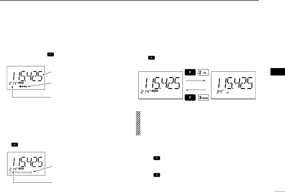
ï‘TO’ or ‘FROM’ flag selection
The to-from flag indicators indicate whether the VOR naviga-
tion information is based on a course leading to the VOR
station or leading away from the VOR station.
Push , then push [3•FROM] or [2•TO] to change the flag
from ‘TO’ to ‘FROM’ or vice versa, respectively.
NOTE:
• When using the ‘TO’ flag and passing through the VOR station,
the ‘TO’ flag changes to the ‘FROM’ flag automatically.
• When turning power ON, the ‘FROM’ flag is selected automati-
cally.
ï Selecting the next VOR station when using
CDI mode (when using the course deviation needle)
q Push , then push [1•DVOR] to select the DVOR mode.
w Push the keypad or rotate [DIAL] to set the next VOR sta-
tion’s frequency.
e Push , then push [4•CDI] to select the CDI mode.
• Select ‘TO’ or ‘FROM’ flag, if desired.
Operating frequency can not be
changed.
Each course deviation arrow
indicates a two-degree deviation.
Course indicator is fixed, but it
can be changed with the tuning
[DIAL] or keypad.
Course deviation needle does not
appear.
Course indicator shows your
direction to (or from) the VOR
station.
2
3
1
4
5
6
7
9
10
8
12
13
11
14
20
6VOR NAVIGATION (IC-A24 ONLY)
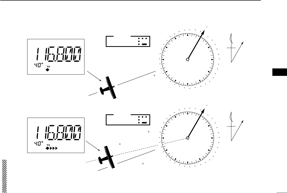
■Flying to a VOR station
The IC-A24 shows the deviation from a VOR station.
q Select a VOR station on your aeronautical chart and push
the keypad or rotate [DIAL] to set the frequency of the
station.
• The course indicator indicates where you are located on a ra-
dial from the VOR station.
• The course indicator shows ‘- -’ when either aircraft is too far
away from the VOR station or the frequency is not set correctly
at the VOR station.
w Select the ‘TO’ flag when flying to the VOR station, or se-
lect the ‘FROM’ flag when flying away from the VOR sta-
tion.
• Push , then push [2•TO] to select ‘TO’.
• Push , then push [3•FROM] to select ‘FROM’.
e Push , then push [4•CDI] to select the CDI (Course
Deviation Indicator) mode.
• The course indicator shows ‘OF’ when the desired VOR signal
cannot be received.
NOTE: When the CDI mode is selected, the operating fre-
quency cannot be changed. To set the operating fre-
quency, select the DVOR mode in advance.
r The course deviation needle appears when your aircraft
is off course from the VOR station.
• ‘Ω’ or ‘≈’ appears to indicate your aircraft is off course to the
right or left, respectively. Correct your course until ‘Ω’ or ‘≈’ dis-
appears. Each arrow represents a two-degree deviation.
t Push , then push [1•DVOR] to exit the CDI mode.
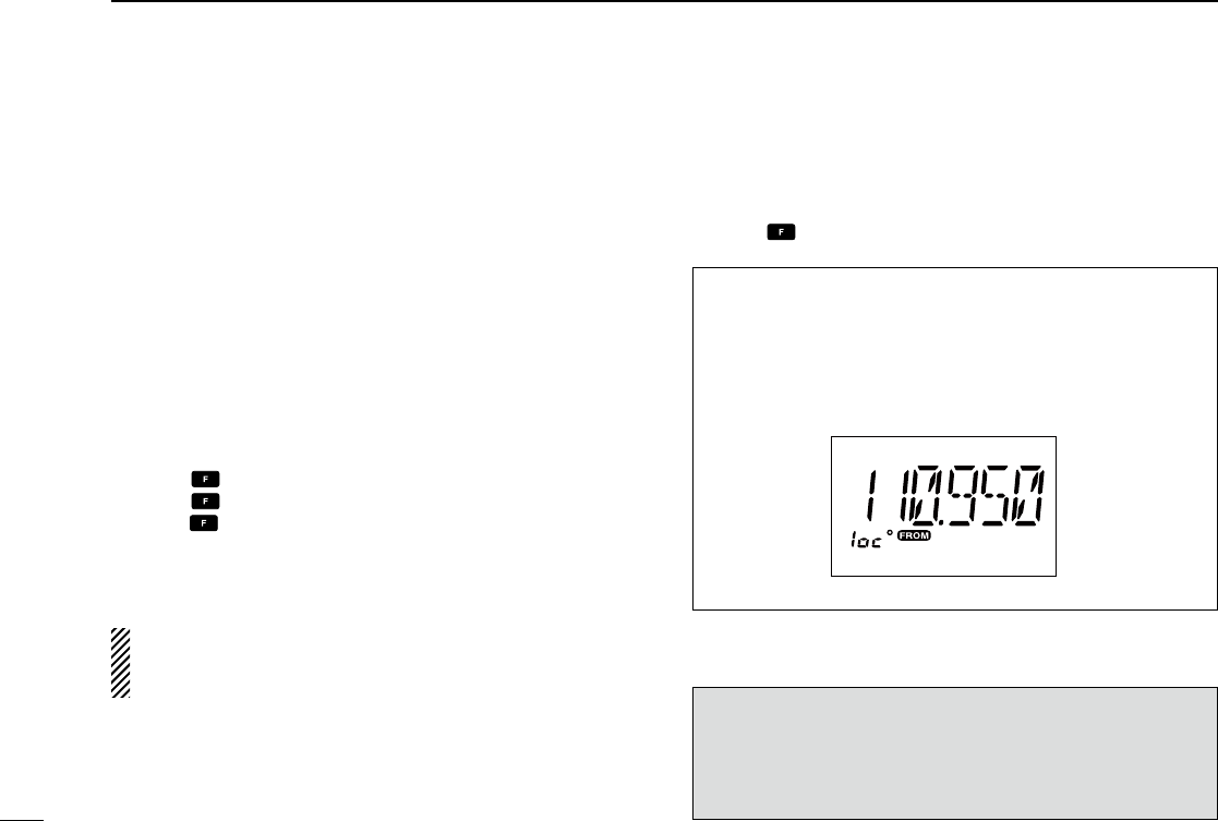
VOR INDICATOR NOTE
‘loc’ appears on the function display as shown below when
a localizer signal is received.
However, the function display does not indicate additional
information about the localizer signal.
NOTE: For only the U.S.A. version
IC-A24’s VOR and CDI Navigation features are supple-
mental aids to navigation only, and are not intended to be
a substitute for accurate (primary) VOR/CDI or landing
service equipment.
21
6
VOR NAVIGATION (IC-A24 ONLY)
VOR
station
0
10
20
30
40
50
60
70
80
90
100
110
120
130
140
150
160
170
180
190
200
210
220
230
240
250
260
270
280
290
300
310 320
330 340
350
NMagnetic
north
Desired course
Aircraft heading 40
123.65
VORTAC
SEATTLE
116.8 Ch 115 SEA
THE AIRCRAFT IS ON COURSE
VOR
station
0
10
20
30
40
50
60
70
80
90
100
110
120
130
140
150
160
170
180
190
200
210
220
230
240
250
260
270
280
290
300
310 320
330 340
350
NMagnetic
north
Aircraft should be
heading 40
Aircraft heading 46
(6 off course)
Flown course
123.65
VORTAC
SEATTLE
116.8 Ch 115 SEA
THE AIRCRAFT IS OFF COURSE
NOTE: The course deviation indica-
tor appears when the aircraft is off
course. In this example, the aircraft
is 6 degrees off course to the left.
The pilot must turn more than 6 de-
grees right to get back on course.
2
3
1
4
5
6
7
9
10
8
12
13
11
14
22
6VOR NAVIGATION (IC-A24 ONLY)
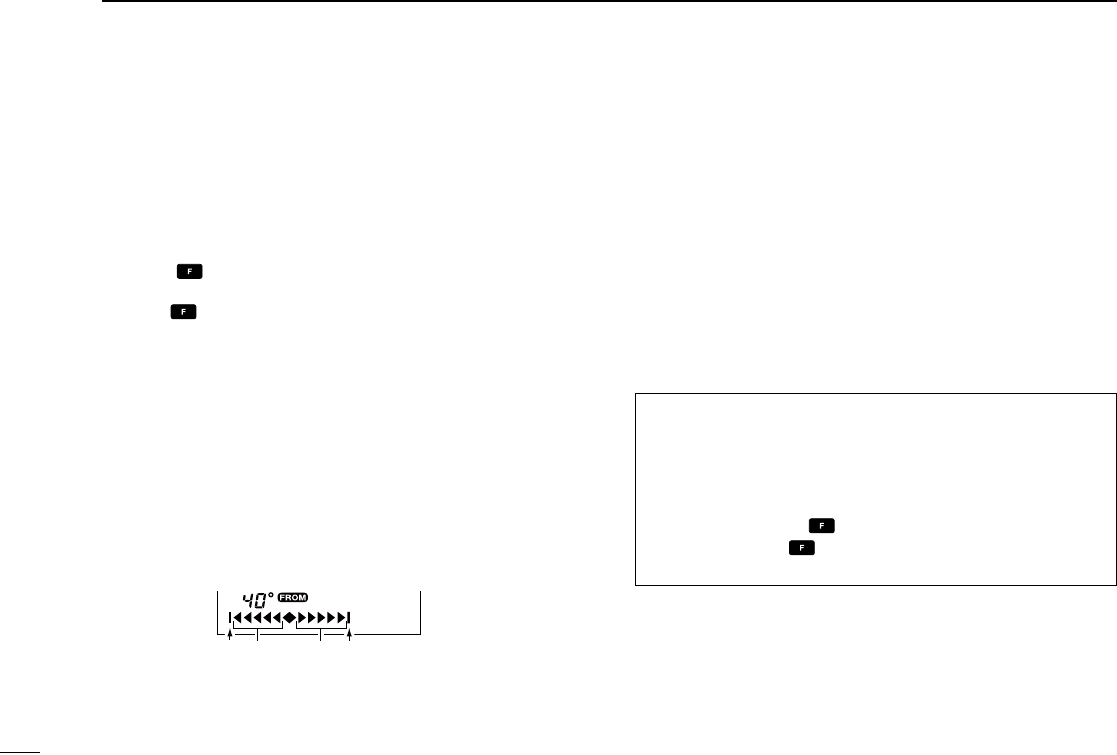
■Entering a desired course
The IC-A24 shows not only the deviation from the VOR sta-
tion but the deviation from the desired course.
q Push the keypad or rotate [DIAL] to set the frequency for
the desired VOR station.
• Push , then push [2•TO] or [3•FROM] to change the to-from
flag.
w Push , then push [4•CDI] to select the CDI mode.
e Set the desired course to the VOR station using the tun-
ing dial or keypad.
• ‘Ω’ or ‘≈’ appears on the function display when your aircraft is
off the desired course.
• When your heading is correct, the ABSS function (see right col-
umn for detail) may be useful instead of course input.
r The course deviation needle points to the right when your
aircraft is off course to the left.
• To get back on course, fly right more than the number of de-
grees indicated by the CDI arrows.
• If the overflow indicator appears on the right side, select a head-
ing plus 10 degrees to the desired course; if the overflow indica-
tor appears on the left side, select a heading minus 10 degrees.
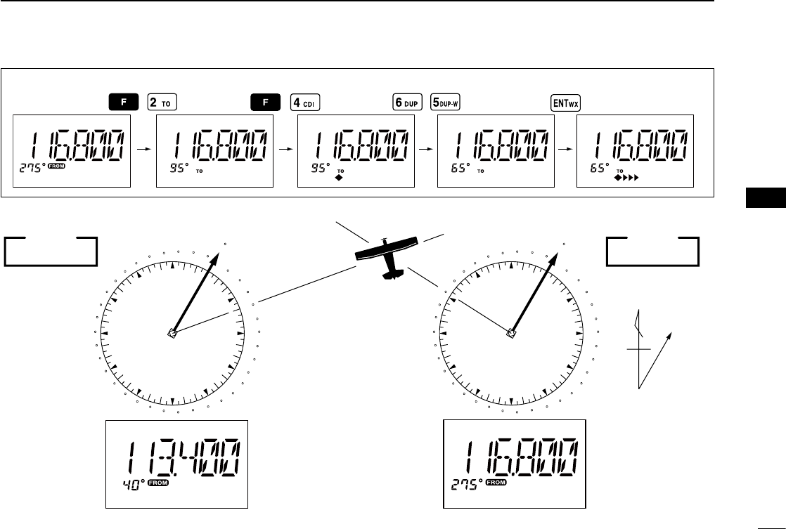
■Crosschecking position
q Select 2 VOR stations on your aeronautical chart.
w Push the keypad or rotate [DIAL] to set the frequency of
one of the VOR station in the DVOR mode.
• The course indicator shows course deviation from the VOR ra-
dial. Note the radial you are on.
e Push the keypad or rotate [DIAL] to set the frequency of
the other VOR station in the DVOR mode.
• Note the radial from the station you are on.
r Extend the radials from each VOR station on the chart.
Your aircraft is located at the point where the lines inter-
sect.
ABSS FUNCTION
In the CDI mode, the Auto Bearing Set System (ABSS)
adds or subtracts the number of degrees indicated by the
CDI arrows from the Omni Bearing Selector (OBS).
To use ABSS, push , then push [2•TO] while using the
‘TO’ flag; or, push , then push [3•FROM] while using the
‘FROM’ flag.
Course
indicator
q
w
Overflow indicator (left)
Overflow indicator (right)
Course deviation needles (left)
e
r
Course deviation needles (right)
To-from flag indicator
wer
q
23
6
VOR NAVIGATION (IC-A24 ONLY)
EXAMPLE: Entering the desired course bearing 65° to a VOR station.
VOR
station
0
10
20
30
40
50
60
70
80
90
100
110
120
130
140
150
160
170
180
190
200
210
220
230
240
250
260
270
280
290
300
310 320
330 340
350
NMagnetic
north
VOR
station
0
10
20
30
40
50
60
70
80
90
100
110
120
130
140
150
160
170
180
190
200
210
220
230
240
250
260
270
280
290
300
310 320
330 340
350
113.4 Ch 81 OLM
VORTAC
OLYMPIA
116.8 Ch 115 SEA
123.65
VORTAC
SEATTLE
CROSSCHECKING POSITION
2
3
1
4
5
6
7
9
10
8
12
13
11
14
24
6VOR NAVIGATION (IC-A24 ONLY)
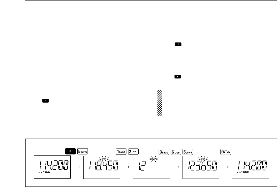
■ Duplex operation
(U.S.A. version only)
The duplex function allows you to call a flight service station
while receiving a VOR station. The duplex function requires
frequency programming for the flight service station in ad-
vance.
ïProgramming a duplex frequency
q Push [CLR•DEL] to select the frequency mode.
w Set a NAV band frequency using the tuning dial or keypad.
• NAV band frequency range: 108.000–117.975 MHz
e Push , then push [5•DUP-W].
• “DUP” flashes and transmit frequency appears.
r Set the frequency of the flight service station using the
tuning dial or keypad. When using the tuning dial, push
[ENT•WX] after setting a frequency.
• The displayed frequency returns to the NAV band frequency.
ïOperating the duplex function
q Set the desired frequency in the NAV band.
• NAV band frequency range: 108.000–117.975 MHz
w Push , then push [6•DUP] to turn the duplex function
ON.
• “DUP” appears on the function display.
e Hold down [PTT] to transmit at the pre-programmed
transmit frequency.
r Release [PTT] to return to receive.
t Push , then push [6•DUP] to cancel the function.
• “DUP” disappears on the function display.
NOTE: A duplex frequency can be programmed into each
memory channel independently. Set a duplex frequency
before programming the memory channel, if desired. The
duplex ON/OFF setting can also be programmed into a
memory channel.
EXAMPLE: Programming 123.65 MHz as the transmit frequency in the duplex function.
25
7
CLONING
Cloning allows you to quickly and easily transfer the
programmed data from one transceiver to another
transceiver, or, data from a PC to a transceiver, using the
optional CS-A24 (#02) cloning software.
ïTransceiver to transceiver cloning
q Connect the OPC-474 CLONING CABLE with adapter
plugs to the [SP/MIC] jack of the master and sub trans-
ceivers.
• The master transceiver is used to send data to the sub trans-
ceiver.
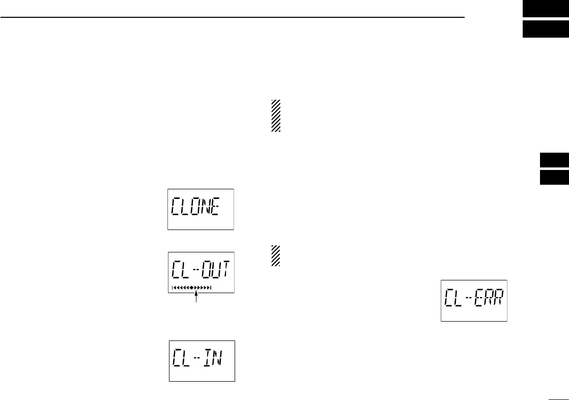
w While holding down [MR•MW], push
[PWR] to enter the cloning mode (to
operate the master transceiver
only).
• “CLONE” appears and the transceivers
enter the clone standby condition.
e Push [MR•MW] on the master trans-
ceiver.
• “CL-OUT” appears in the master trans-
ceiver’s display.
• “COURSE DEVIATION NEEDLES”
shows that cloning is taking place
• “CL-IN” appears automatically in the
sub transceiver’s display.
r When cloning is finished, turn power OFF, then ON again
to exit the cloning mode.
NOTE: DO NOT transfer the data from a IC-A24 to a IC-
A6, when the data contains the NAV band data. In such
case, a cloning error may occur.
ïCloning using PC
Data can be cloned to and from a PC (Microsoft® Windows®
XP) using the optional CS-A24 (#02) cloning software and
the optional OPC-478 (RS-232C type), OPC-478U or OPC-
478UC (USB type) cloning cable. Consult the CS-A24
(#02) cloning software HELP file for details.
ïCloning error
NOTE: DO NOT push [ENT•WX] on the sub transceiver
during cloning. This will cause a cloning error.
When the display at right appears, a
cloning error has occurred.
In this case, both transceivers automatically return to the
clone standby condition and cloning must be repeated.
Microsoft and Windows are registered trademarks of Micro-
soft Corporation in the U.S.A. and other countries.
“COURSE DEVIATION
NEEDLES” shows that
cloning is taking place.
2
3
1
4
5
6
7
9
10
8
12
13
11
14
26
8BATTERY PACKS
■Battery cautions
R DANGER! NEVER incinerate used battery packs.
Internal battery gas may cause an explosion.
R DANGER! NEVER immerse battery pack in water.
If the battery pack becomes wet, be sure to wipe it dry im-
mediately (particularly the battery terminals BEFORE at-
taching it to the transceiver).
R DANGER! NEVER short the terminals of the bat-
tery pack. Also, current may flow into nearby metal objects,
such as a necklace, etc. Therefore, be careful when carrying
with, or placing near metal objects, carrying in handbags,
etc.
CAUTION: NEVER insert battery pack/transceiver
(with the battery pack attached) with wet or soiled into the
charger. This may result in corrosion of the charger terminals
or damage to the charger. The charger is not waterproof and
water can easily get into it.
If your battery pack seem to have no capacity even after
being charged, completely discharge them by leaving the
power ON overnight. Then, fully charge the battery pack
again. If the batteries still do not retain a charge (or very lit-
tle), new battery pack must be purchased.
■Battery charging
Prior to using the transceiver for the first time, the battery
pack must be fully charged for optimum life and operation.
CAUTION: To avoid damage to the transceiver, turn the
power OFF while charging.
• Recommended temperature range for charging:
+10°C to +40°C (+50°F to +104°F)
• Use the supplied AC adapter on regular charging. NEVER
use another manufacture’s adapters.
• Use the specified chargers (BC-119N, BC-121N and
BC-144N). NEVER use another manufacture’s charger.
CAUTION: NEVER connect DC power to the transceiver
when installing Alkaline batteries. Such a connection will
damage the transceiver.
D Recycling information (U.S.A. only)
The product that you have purchased contains
a rechargeable battery. The battery is recycla-
ble. At the end of its life, under various state
and local laws, it may be illegal to dispose of
this battery into the municipal waste stream.
Call 1-800-822-8837 for battery recycling op-
tions in your area or contact your dealer.
Turn the transceiver power OFF when charging the battery
pack. Otherwise, the battery pack may not fully charge or
charge properly.
27
8
BATTERY PACKS
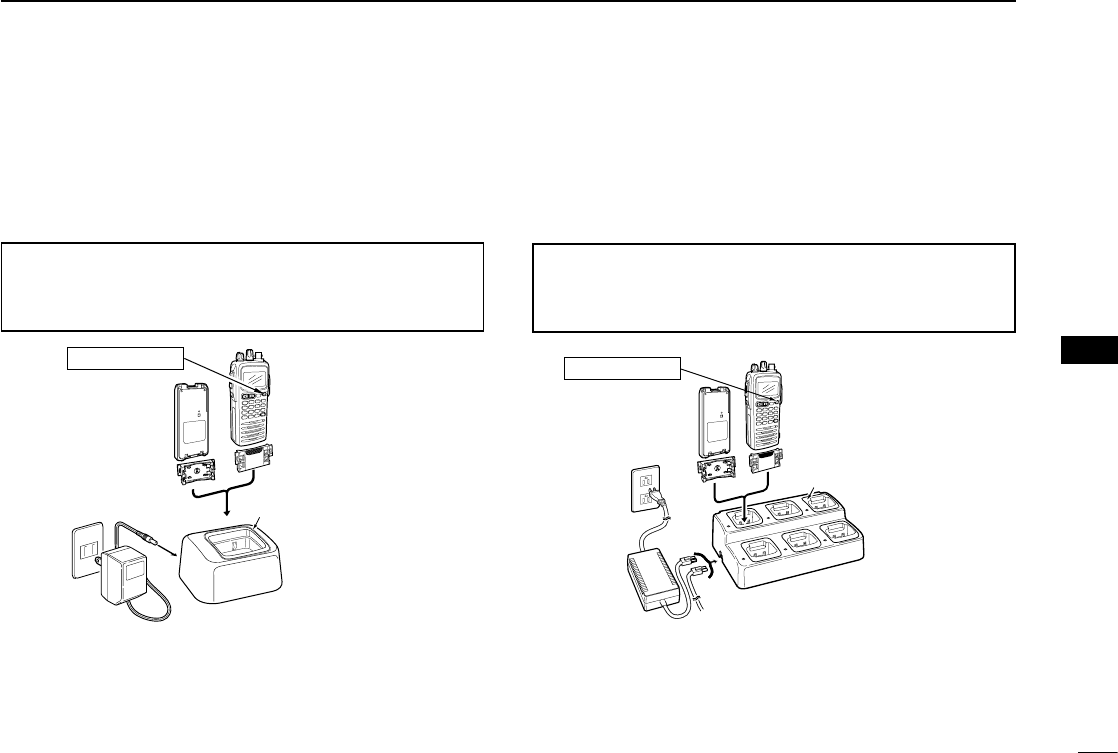
ïRegular charging
q Attach the battery pack to the transceiver.
w Be sure to turn the transceiver power OFF.
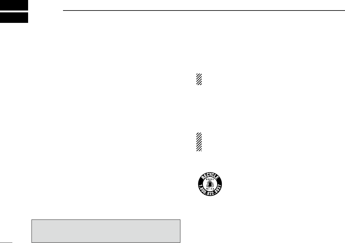
e Connect the wall charger or optional cable (CP-20) as
shown below.
r Charge the battery pack approximately 8 hours, depend-
ing on the remaining power condition.
DO NOT charge the BP-210N more than 12 hours. Other-
wise, the BP-210N will be damaged.
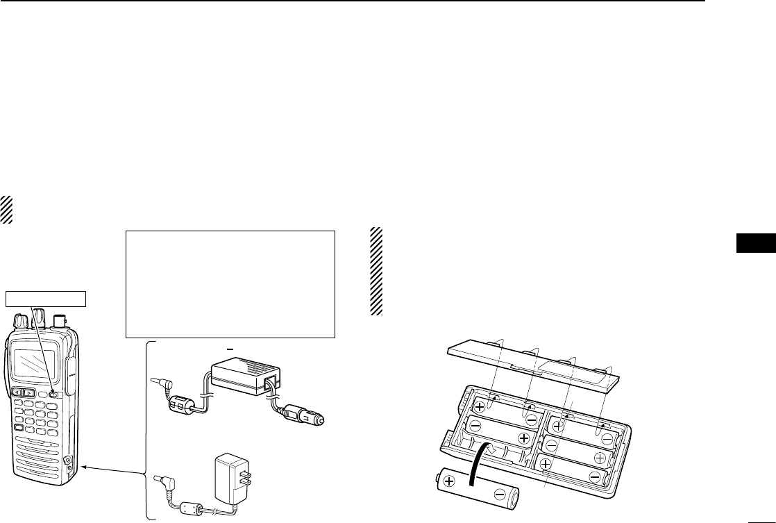
■Optional battery case
When using a battery case attached to the transceiver, in-
stall 6 × AA (LR6) size Alkaline batteries, as illustrated
below.
q Remove the battery case from the transceiver.
w Install 6 × AA (LR6) size Alkaline batteries.
• Be sure to observe the correct polarity.
CAUTION:
• When installing batteries, make sure they are all the
same brand, type and capacity. Also, do not mix new
and old batteries together.
• Keep battery contacts clean. It’s a good idea to clean
battery terminals once a week.
To [DC 11V]
IC-A24/A6 with the
attached battery pack
CP-20 (for 11 24 V)
(optional)
To the cigarette
lighter socket
To AC outlet
The shape may
differ depending
on the version.
Wall charger
Tu rn power OFF
R WARNING!
• NEVER modify the CP-20. A modifica-
tion could cause a fire or electrocution.
• NEVER cut or fray the CP-20’s power
cable when disconnecting/connecting
the CP-20 from/to the cigarette lighter
socket.
2
3
1
4
5
6
7
9
10
8
12
13
11
14
28
8BATTERY PACKS
■Optional battery chargers
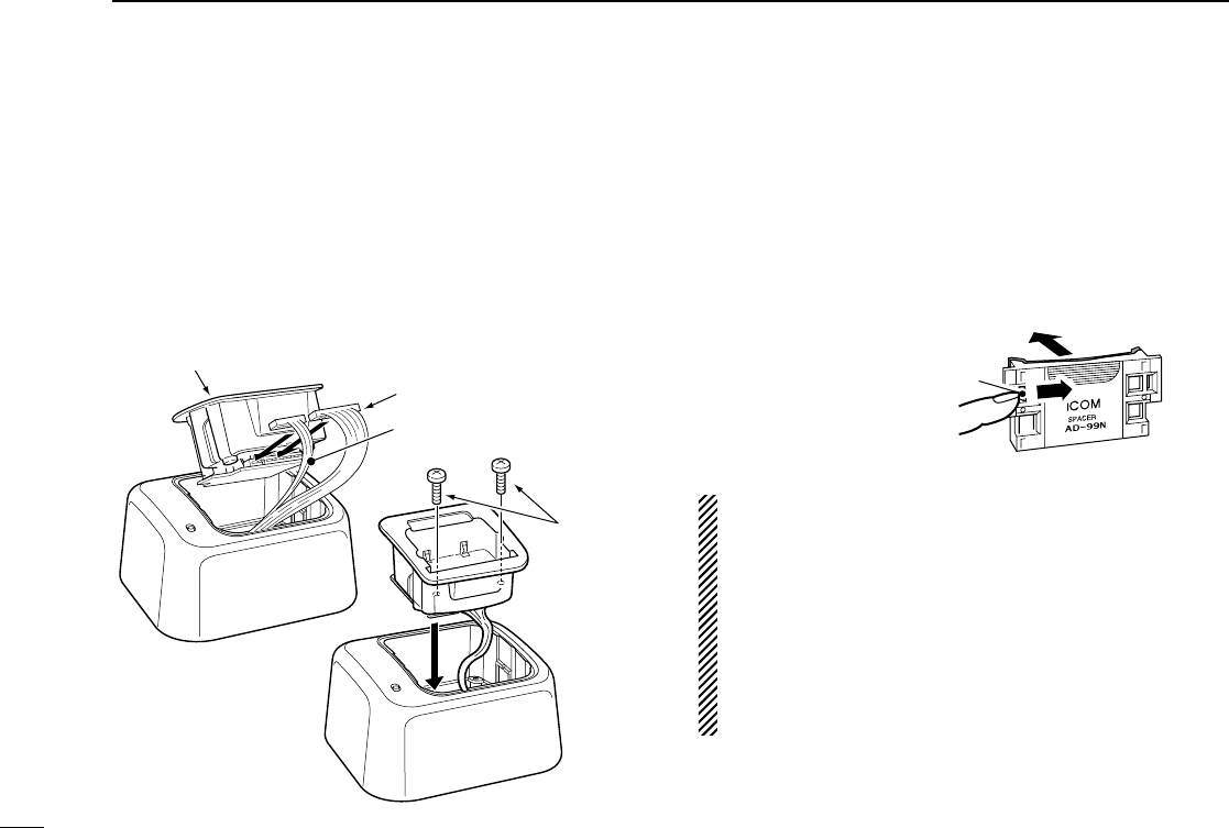
ïAD-101 installation
The AD-101 cHarger adaPter must be installed into the
BC-119N or BC-121N before battery charging.
Connect the AD-101 cHarger adaPter and the BC-119N/
BC-121N as below (q), then install the AD-101 into the
holder space of the BC-119N or BC-121N with the supplied
screws (w).
ïAbout AD-99N
The adapter (Spacer A) only is required for IC-A24/A6.
When removing the spacer (Spacer B/C), push the latch
carefully with your finger to remove the spacer (Spacer B/C)
from the adapter (Spacer A).
CAUTION:
• DO NOT push or force the latch with a screw driver, etc.,
to remove it.
• DO NOT bend the latch when the adapter and spacer
are not joined together. This will cause weakening of the
latch plastic.
• Both cases may break the latch and it may not be able
to be reattached.
• BE CAREFUL not to lose the spacer (Spacer B/C) after
removing it from the adapter (Spacer A).
Push the latch
carefully.
Remove the spacer (Spacer B/C)
from the adapter
.
Desktop charger adapter
q
w
10-pin connector
3-pin connector
Supplied
screws
29
ïRapid charging with the BC-119N+AD-101
The optional BC-119N provides rapid charging of the battery
packs. The following are additionally required.
• AD-101 charger adapter.
• An AC adapter (may be supplied with BC-119N depending on ver-
sions) or the DC power cable (CP-20).
ïRapid charging with the BC-121N+AD-101
The optional BC-121N allows up to 6 battery packs to be
charged simultaneously. The following are additionally re-
quired.
• Six AD-101 charger adapters.
• An AC adapter (BC-157) or the DC power cable (OPC-656).
AD-99N (supplied
with AD-101)
AC
adapter
IC-A24/A6
BP-209N/BP-210N
Turn power OFF
The AD-101 charger
adapter
is installed in the slot.
IC-A24/A6
BP-209N/BP-210N
AD-101 charger adapters are
installed in each slot.
DC power cable (OPC-656)
(Connect with the DC power supply;
13.8 V/at least 7 A)
Turn power OFF
AD-99N (supplied
with AD-101)
AC adapter
(BC-157:
Purchase
separately)
The adapter (Spacer A) only is required for IC-A24/A6. When re-
moving the spacer (Spacer B/C), push the latch carefully with your
finger to remove the spacer (Spacer B/C) from the adapter
(Spacer A). See p. 28 for details.
The adapter (Spacer A) only is required for IC-A24/A6. When re-
moving the spacer (Spacer B/C), push the latch carefully with your
finger to remove the spacer (Spacer B/C) from the adapter
(Spacer A). See p. 28 for details.
8
BATTERY PACKS
2
3
1
4
5
6
7
9
10
8
12
13
11
14

30
9SPECIFICATIONS
ïGeneral
• Frequency coverage (MHz) : TX 118.000 to 136.9917
RX 108.000 to 136.9917*1
WX 161.650 to 163.275*4
• Mode : 6K00A3E/5K60A3E
16K0G3E (161.65 to 163.275 MHz)
*4
• Channel spacing : 25 kHz/8.33 kHz
• Number of memory channels : 200 (20 CH × 10 BANKS)
• Power supply requirement : Specified battery packs/case or
11.0 V DC at the external DC jack
• Usable temperature range : –10˚C to +60˚C (+14°F to +140°F)
• Current drain : Tx 1.5 A typical
Rx 70 mA typical (at stand by)
300 mA typical (at AF maxi-
mum)
• Antenna connector : BNC 50 Ω (nominal)
• Dimensions : 54(W) × 129.3(H) × 35.5(D) mm
(projections not included)
2.1(W) × 5.1(H) × 1.4(D) inch
• Weight : Approximately 180 g (6.35 oz)
(Without the battery pack and antenna.)
ïTransmitter
• Output power : 5.0 W (PEP) typical
1.5 W (CW) typical
• Modulation : Low level modulation
• Modulation limiting : 70 to 100%
• Frequency stability : ±1 ppm
• Audio harmonic distortion : Less than 10% (at 60% modulation)
• Hum and noise ratio : More than 35 dB
•
Spurious emissions
:
More than 46 dB (except operating
frequency ±62.5 kHz range)
• Microphone connector : 3-conductor 2.5(d) mm (1/10˝)/
more than 100 kΩ
ïReceiver
• Receive system : Double conversion
superheterodyne
• Intermediate frequencies : 1st 46.35 MHz, 2nd 450 kHz
• Sensitivity
VOR (AM 6 dB S/N)
: –3 dBµ typical
COM (AM 6 dB S/N)
: –6 dBµ typical
WX (FM 12 dB SINAD)
: –13 dBµ typical
• Squelch sensitivity (Threshold) : AM Less than 0 dBµ
FM Less than –5 dBµ*4
• Selectivity : 6 dB (More than 7.5 kHz)*2
60 dB (Less than 25 kHz)*2
6 dB (Less than 2.778 kHz)*3
60 dB (Less than 7.37 kHz)*3
• Spurious response : AM More than 60 dB
rejection FM More than 30 dB*4
• Audio output power : 500 mW typical (at 10% distortion
with an 8 Ω load, 30% modulation)
• Noise and hum : More than 35 dB at 30% modula-
tion
• External speaker connector : 3-conductor 3.5 (d) mm (1/8˝)/8 Ω
*1: IC-A24 only. (IC-A6 frequency coverage is from 118.000 to 136.9917 MHz.)
*2: at 25 kHz channel spacing.
*3: at 8.33 kHz channel spacing.
*4: U.S.A. version only.
Measurements made in accordance with RTCA.
All stated specifications are subject to change without notice
or obligation.

31
9
SPECIFICATIONS (VFO CHANNEL ID LIST)
2
3
1
4
5
6
7
9
10
8
12
13
11
14
• Channel spacing: 25 kHz (Actual frequency is displayed.)
Operating Frequency
(MHz)
Channel spacing
(kHz)
Channel ID
(Displayed Frequency)
118.0000 25 118.000
118.0250 25 118.025
118.0500 25 118.050
118.0750 25 118.075
118.1000 25 118.100
• Channel spacing: 8.33 kHz
Operating Frequency
(MHz)
Channel spacing
(kHz)
Channel ID
(Displayed Frequency)
118.0000 8.33 118.005
118.0083 8.33 118.010
118.0167 8.33 118.015
118.0250 8.33 118.030
118.0333 8.33 118.035
118.0417 8.33 118.040
118.0500 8.33 118.055
118.0583 8.33 118.060
118.0667 8.33 118.065
118.0750 8.33 118.080
118.0833 8.33 118.085
118.0917 8.33 118.090
118.1000 8.33 118.105
• Channel spacing: 8.33 kHz/25 kHz
Operating Frequency
(MHz)
Channel spacing
(kHz)
Channel ID
(Displayed Frequency)
118.0000 25 118.000
118.0000 8.33 118.005
118.0083 8.33 118.010
118.0167 8.33 118.015
118.0250 25 118.025
118.0250 8.33 118.030
118.0333 8.33 118.035
118.0417 8.33 118.040
118.0500 25 118.050
118.0500 8.33 118.055
118.0583 8.33 118.060
118.0667 8.33 118.065
118.0750 25 118.075
118.0750 8.33 118.080
118.0833 8.33 118.085
118.0917 8.33 118.090
118.1000 25 118.100
118.1000 8.33 118.105
These tables show just the display example between 118.0000 MHz
and 118.1000 MHz, not show all frequencies in the band.

32
10 OPTIONS
ïBATTERY CASE AND PACKS
• BP-208N battery case
Battery case for 6 × AA (LR6) Alkaline cells.
• BP-209N Ni-Cd battery PacK
7.2 V/1100 mAh Ni-Cd battery pack.
• BP-210N Ni-MH battery PacK
7.2 V/1500 mAh (Min.)/1650 mAh (Typ.) Ni-MH battery pack.
ïCHARGERS
• BC-167SA/SD/SC/SV wall cHarger
The same as supplied with the transceiver.
• BC-119N desKtoP cHarger + AD-101 cHarger adaPter
+ BC-145 ac adaPter
For rapid charging of battery packs. An AC adapter is supplied with
the charger depending on versions. Charging time: approximately
1.5 to 2 hours.
• BC-121N Multi-cHarger + AD-101 cHarger adaPter (6 pcs.)
+ BC-157 ac adaPter
For rapid charging of up to 6 battery packs (six AD-101’s are re-
quired) simultaneously. An AC adapter should be purchased sepa-
rately. Charging time: approximately 1.5 to 2 hours.
• BC-144N desKtoP cHarger
For rapid charging of BP-209N (Ni-Cd) and BP-210N (Ni-MH).
ïMICROPHONE
• HM-234 sPeaKer MicroPHone
Combination speaker and microphone.
ïBELT CLIPS
• MB-103 belt cliP
The same as supplied with the transceiver.
• MB-86 swivel belt cliP
Belt clip for swivel type.
• MB-96F/96N leatHer belt Hanger
➥MB-96F: Attaches with the supplied belt clip (Fixed type).
➥MB-96N: Belt hanger for swivel type.
ïDC CABLES
• CP-20 cigarette ligHter cable
➥ Charges the battery pack through a cigarette lighter socket*.
➥Operates IC-A24/A6 through a cigarette lighter socket*.
*Both 12 V and 24 V batteries are available.
• OPC-656 dc Power cable for BC-121N
Charges the battery pack using 13.8 V power source instead of the
AC adapter for BC-121N.
ïOTHER OPTIONS
• OPC-499 Headset adaPter cable
When using an optional headset (3rd party products) via the
adapter, the transceiver outputs your transmitted voice to the
headset for monitoring.
• LC-159 carrying case
Helps protect the transceiver from scratches, etc.
Different versions of this radio use different options. Ask
your authorized dealer for details.
Approved Icom optional equipment is designed for optimal
performance when used with an Icom transceiver.
Icom is not responsible for the destruction or damage to an
Icom transceiver in the event the Icom transceiver is used
with equipment that is not manufactured or approved by
Icom.
33
11
OPTIONAL HEADSET CONNECTION
2
3
1
4
5
6
7
9
10
8
12
13
11
14
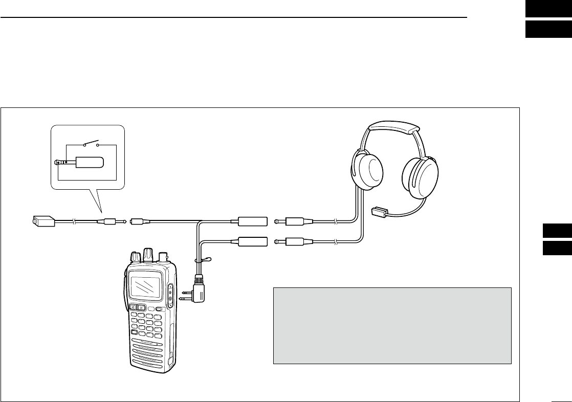
ïOPC-499 (HEADSET ADAPTER) connection
When using a headset (3rd party products) via the OPC-499 HEADSET ADAPTER, the transceiver outputs your transmitted voice
to the headset for monitoring. See “■ Side tone function” (p. 11) when setting the side tone level.
PTT
OPC-499
IC-A24/A6
PTT switch
HEADSET
(Must be purchased
separately)
Use a PTT switch with a
3.5 mm (1/8") diameter
plug, if required.
NOTICE!
Some headsets do not work properly when used with the
IC-A24/A6.
Therefore, ask your dealer for details about headsets
compatible for operation with the IC-A24/A6 with the
headset.

34
12 SAFETY TRAINING INFORMATION
WARNING
Your Icom radio generates RF electromagnetic energy during
transmit mode. This radio is designed for and classified as
“Occupational Use Only”, meaning it must be used only dur-
ing the course of employment by individuals aware of the
hazards, and the ways to minimize such hazards. This radio
is NOT intended for use by the “General Population” in an
uncontrolled environment.
This radio has been evaluated for compliance at the distance of 2.5 cm with
the FCC RF exposure limits for “Occupational Use Only”. In addition, your
Icom radio complies with the following Standards and Guidelines with regard
to RF energy and electromagnetic energy levels and evaluation of such levels
for exposure to humans:
• FCC OET Bulletin 65 Edition 97-01 Supplement C, Evaluating Compli-
ance with FCC Guidelines for Human Exposure to Radio Frequency
Electromagnetic Fields.
• American National Standards Institute (C95.1-1992), IEEE Standard for
Safety Levels with Respect to Human Exposure to Radio Frequency
Electromagnetic Fields, 3 kHz to 300 GHz.
• American National Standards Institute (C95.3-1992), IEEE Recom-
mended Practice for the Measurement of Potentially Hazardous Electro-
magnetic Fields– RF and Microwave.
• The following accessories are authorized for use with this product. Use of
accessories other than those specified may result in RF exposure levels
exceeding the FCC requirements for wireless RF exposure.; Belt Clip
(MB-86/103), Speaker Microphone (HM-234), Rechargeable Ni-MH Bat-
tery Pack (BP-210N) and Alkaline Battery Case (BP-208N).
To ensure that your expose to RF electromagnetic en-
ergy is within the FCC allowable limits for occupational
use, always adhere to the following guidelines:
• DO NOT operate the radio without a proper antenna attached, as this
may damage the radio and may also cause you to exceed FCC RF expo-
sure limits. A proper antenna is the antenna supplied with this radio by
the manufacturer or antenna specifically authorized by the manufacturer
for use with this radio.
• DO NOT transmit for more than 50% of total radio use time (“50% duty
cycle”). Transmitting more than 50% of the time can cause FCC RF expo-
sure compliance requirements to be exceeded. The radio is transmitting
when “ ” appears on the function display. You can cause the radio to
transmit by pressing the “PTT” switch.
• ALWAYS keep the antenna at least 2.5 cm (1 inch) away from the body
when transmitting and only use the Icom belt-clips which are listed on
page 32 when attaching the radio to your belt, etc., to ensure FCC RF
exposure compliance requirements are not exceeded. To provide the re-
cipients of your transmission the best sound quality, hold the antenna at
least 5 cm (2 inches) from your mouth, and slightly off to one side.
The information listed above provides the user with the information needed to
make him or her aware of RF exposure, and what to do to assure that this
radio operates with the FCC RF exposure limits of this radio.
Electromagnetic Interference/Compatibility
During transmissions, your Icom radio generates RF energy that can possibly
cause interference with other devices or systems. To avoid such interference,
turn off the radio in areas where signs are posted to do so. DO NOT operate
the transmitter in areas that are sensitive to electromagnetic radiation such as
hospitals and blasting sites.
Occupational/Controlled Use
The radio transmitter is used in situations in which persons are exposed as
consequence of their employment provided those persons are fully aware of
the potential for exposure and can exercise control over their exposure.
CAUTION

35
12
INFORMATION EN MATIÈRE DE SÉCURITÉ
Votre radio Icom produit une énergie électromagnétique
de radiofréquences (RF), en mode de transmission. Cette
radio est conçue pour un «usage professionnel seulement»
et classée comme tel, ce qui signifie qu'elle doit être utilisée
uniquement dans le cadre d'un travail par des personnes
conscientes des dangers et des mesures visant à minimiser
ces dangers. Elle N'EST PAS conçue pour une «utilisation
grand public», dans un environnement non contrôlé.
Cet appareil a été évalué et jugé conforme, à 2,5 cm, aux limites d'exposi-
tion aux RF de la FCC, pour une « utilisation grand public ». En outre, votre
radio Icom satisfait les normes et directives qui suivent en matière de niveaux
d'énergie et d'énergie électromagnétique de RF et d'évaluation de tells niveaux
en ce qui concerne l'exposition humaine :
• Supplément C, édition 97-01, du Bulletin OET n° 65 de la FCC, «Eva-
luating Compliance with FCC Guidelines for Human Exposure to Radio
Frequency Electromagnetic Fields».
• Norme de l’American National Standards Institute (ANSI): IEEE C95.1-
1992 sur les niveaux de sécurité compatibles avec l'exposition humaine
aux champs électromagnétiques de radiofréquences (3 kHz à 300 GHz).
• Norme de l’ANSI : IEEE C95.3-1992 sur la méthode d’évaluation recom-
mandée du champ magnétique potentiellement dangereux des radiofré-
quences et des micro-ondes.
• Les accessoires qui suivent sont approuvés pour une utilisation avec ce
produit. L'utilisation d'accessoires autres que ceux précisés peut entraî-
ner des niveaux d'exposition aux RF supérieures aux limites établies par
la FCC en matière d'exposition aux RF sans fil.; Attache pour ceinture
(MB-86/103), microphone haut-parleur (HM-234), bloc-piles rechargeable
au Ni-MH (BP210N) et boiter piles (BP-208N).
Afin de vous assurer que votre exposition à une énergie
électromagnétique de RF se situe dans les limites permises
par la FCC pour une utilisation grand public, veuillez en tout
temps respecter les directives suivantes :
• NE PAS faire fonctionner la radio sans qu'une antenne appropriée y soit
fixée, car ceci risque d'endommager la radio et causer une exposition
supérieure aux limites établies par la FCC. L'antenne appropriée est celle
qui est fournie avec cette radio par le fabricant ou une antenne spéciale-
ment autorisée par le fabricant pour être utilisée avec cette radio.
• NE PAS émettre pendant plus de 50% du temps total d'utilisation de l'ap-
pareil («50% du facteur d'utilisation»). Émettre pendant plus de 50% du
temps total d'utilisation peut causer une exposition aux RF supérieure
aux limites établies par la FCC. La radio est en train d’émettre lorsque
le témoin du “ ” s’affiche sur l’écran ACL. La radio émettra si vous
appuyez sur le bouton du microphone.
• TOUJOURS tenir l'antenne éloignée d'au moins 2,5 cm de votre corps
au moment d'émettre et utiliser uniquement l'attache pour ceinture Icom
illustrée à la p. 32, lorsque vous attachez la radio à votre ceinture, ou à
autre chose, de façon à vous assurer de ne pas provoquer une exposition
aux RF supérieure aux limites fixées par la FCC. Pour offrir à vos interlo-
cuteurs la meilleure qualité de transmission possible, tenez l'antenne à au
moins 5 cm de votre bouche et légèrement de côté.
Les renseignements ci-dessus fournissent à l'utilisateur toute l'information né-
cessaire sur l'exposition aux RF et sur ce qu'il faut faire pour assurer que cette
radio fonctionne en respectant les limites d'exposition aux RF établies par la
FCC.
Interférence électromagnétique et compatibilité
En mode de transmission, votre radio Icom produit de l'énergie de RF qui peut
provoquer des interférences avec d'autres appareils ou systèmes. Pour éviter
de telles interférences, mettez la radio hors tension dans les secteurs où une
signalisation l’exige. NE PAS faire fonctionner l'émetteur dans des secteurs
sensibles au rayonnement électromagnétique tels que les hôpitaux, les aéro-
nefs et les sites de dynamitage.
Usage professionnel/contrôlé
Ce radio émetteur est utilisé dans des cas où des personnes sont exposées en
raison de leur travail, pourvu qu'elles soient conscientes du risque d'exposition
et qu'elles puissent exercer un contrôle sur cette exposition.
AVERTISSEMENT
MISE EN GARDE
2
3
1
4
5
6
7
9
10
8
12
13
11
14

36
13 FOR CLASS A UNINTENTIONAL RADIATORS
This equipment has been tested and found to comply with
the limits for a Class A digital device, pursuant to part 15 of
the FCC Rules. These limits are designed to provide reason-
able protection against harmful interference when the equip-
ment is operated in a commercial environment. This
equipment generates, uses, and can radiate radio frequency
energy and, if not installed and used in accordance with the
instruction manual, may cause harmful interference to radio
communications. Operation of this equipment in a residential
area is likely to cause harmful interference in which case the
user will be required to correct the interference at his own
expense.
37
14
TROUBLESHOOTING
If your transceiver seems to be malfunctioning, please check the following points before sending it to a service center.
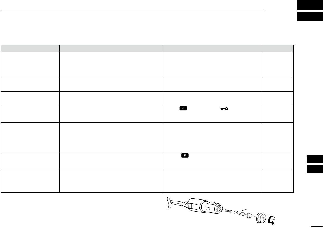
Fuse 8 A
ïCP-20 fuse replacement
If the fuse blows or the receiver stops functioning while
operating with the optional CP-20 cigarette ligHter cable,
find the source of the problem if possible, and replace the
damaged fuse with a new rated one (FGB 8 A) as shown
right.
PROBLEM POSSIBLE CAUSE SOLUTION REF.
No power comes on. • The battery is exhausted.
• Bad connection for the battery pack.
• The CP-20’s fuse is blown.
• Recharge the battery pack.
• Check the connection to the transceiver.
• Check for the cause, then replace the
CP-20’s fuse to new one.
pp. 26–29
p. 1
p. 37
No sound comes from
the speaker. • Squelch level is too deep.
• Volume level is too low.
• Set squelch to the threshold point.
• Set [VOL] to a suitable level.
p. 9
p. 9
Transmitting impossible. • WX channels or NAV band is selected.
• The battery is exhausted.
• Set COM band in frequency mode.
• Recharge the battery pack.
p. 8
pp. 26–29
Operating frequency or
memory channel can not
be changed.
• Lock function is activated. • Push , then push [7• ].p. 11
Scan does not start. • All memory channels in the selected bank
are not programmed as “TAG” channels.
• Squelch is open.
• There is not more than 2 memorized
channels.
• Set the “TAG” settings of desired
channels.
• Set the squelch level to tighten.
• Program 2 or more memory channels.
p. 17
p. 9
p. 16
No beep sounds. • Beep tones turned OFF. • Push , then push [8•BEEP], and
rotate [DIAL] to adjust the beep tone
level.
p. 11
When using an optional
HM-234, your voice
hears from the speaker
during transmitting.
• The side tone function is activated. • Push [PTT], then rotate [DIAL] to set the
monitoring level to ‘ST-0’ (The side tone
function is OFF).
p. 11
2
3
1
4
5
6
7
9
10
8
12
13
11
14

38
INDEX
– A –
About AD-99N ................................................................................28
Accessing the 121.5 MHz emergency frequency ...........................11
ACCESSORY ATTACHMENT ...........................................................1
AD-101 installation .........................................................................28
ANL function ..................................................................................... 9
Antenna ............................................................................................1
– B –
BASIC OPERATION .........................................................................8
BATTERY CASE AND PACKS........................................................32
Battery cautions ..............................................................................26
Battery charging .............................................................................26
Battery pack replacement .................................................................1
BATTERY PACKS ...........................................................................26
BC-119N+AD-101 ..........................................................................29
BC-121N+AD-101 ..........................................................................29
Belt clip ............................................................................................. 1
BELT CLIPS ....................................................................................32
– C –
Channel spacing setting ...................................................................9
CHARGERS ...................................................................................32
Clearing the memory contents .......................................................14
CLONING .......................................................................................25
Cloning error ...................................................................................25
Cloning using PC ............................................................................25
COM band scan ..............................................................................16
CP-20 fuse replacement .................................................................37
Crosschecking position ...................................................................22
– D –
DC CABLES ...................................................................................32
Deletes the stored recall channel ...................................................10
Duplex operation ............................................................................24
– E –
Entering a desired course...............................................................22
EXPLICIT DEFINITIONS ................................................................... i
– F –
Flying to a VOR station ................................................................... 20
FOR CLASS A UNINTENTIONAL RADIATORS ............................36
FOREWORD .....................................................................................i
Function display ................................................................................ 6
– G –
General ........................................................................................... 30
– I –
IMPORTANT ...................................................................................... i
INDEX .............................................................................................38
– L –
Lock function ..................................................................................11
Low battery indicator ......................................................................10
– M –
Memory channel selection ..............................................................12
Memory names ...............................................................................14
MEMORY OPERATION ..................................................................12
Memory scan ..................................................................................16
MICROPHONE ............................................................................... 32
– O –
OPC-499 (HEADSET ADAPTER) connection ................................ 33
Operating the duplex function .........................................................24
Optional battery case .....................................................................27
Optional battery chargers ............................................................... 28
OPTIONAL HEADSET CONNECTION ..........................................33
OPTIONS .......................................................................................32
OTHER OPTIONS .......................................................................... 32
– P –
Panel description ..............................................................................2
PANEL DESCRIPTION .....................................................................2

39
INDEX
2
3
1
4
5
6
7
9
10
8
12
13
11
14
PRECAUTION .................................................................................. ii
Programming a duplex frequency ...................................................24
Programming a memory channel ...................................................13
Programming memory names ........................................................14
– R –
Rapid charging with the BC-119N+AD-101 .................................... 29
Rapid charging with the BC-121N+AD-101 .................................... 29
Recall function ................................................................................ 10
Recalling the stored frequencies ....................................................10
Receiver .........................................................................................30
Receiving ..........................................................................................9
Regular charging ............................................................................27
Replaces the stored recall channel ................................................10
– S –
SAFETY TRAINING INFORMATION .............................................. 34
SCAN OPERATION ........................................................................ 16
Scan types ......................................................................................16
Selecting a weather channel ...........................................................8
Selecting the next VOR station when using CDI mode
(when using the course deviation needle) ......................................19
Setting a frequency ...........................................................................8
Setting a squelch level ......................................................................9
Setting beep tone ...........................................................................11
Setting the side tone level ...............................................................11
Setting weather alert function .........................................................11
Side tone function ...........................................................................11
SPECIFICATIONS ..........................................................................30
SUPPLIED ACCESSORIES .............................................................. i
– T –
TABLE OF CONTENTS ................................................................... iii
“TAG” channel setting .....................................................................17
‘TO’ or ‘FROM’ flag selection...........................................................19
To select the CDI mode ..................................................................19
To select the DVOR mode ..............................................................19
Transceiver to transceiver cloning ..................................................25
Transferring memory contents ........................................................ 12
Transmitter ...................................................................................... 30
Transmitting ......................................................................................9
TROUBLESHOOTING ....................................................................37
– U –
Using keypad .................................................................................... 8
Using the tuning dial ......................................................................... 8
– V –
VOR functions ................................................................................19
VOR indicators................................................................................18
VOR NAVIGATION (IC-A24 ONLY).................................................18
– W –
Weather channel scan .................................................................... 17

1-1-32 Kamiminami, Hirano-ku, Osaka 547-0003, Japan
Printed on recycled paper with soy ink.
A-6987D-1EX-wa
Printed in Japan
© 2011–2017 Icom Inc.